7.0 components we don’t consider trigonometry until later
TRANSCRIPT
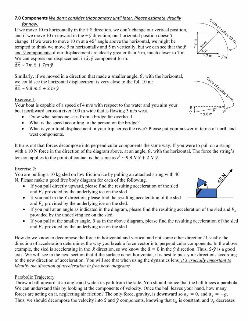
7.0 Components We don’t consider trigonometry until later. Please estimate visually for now.
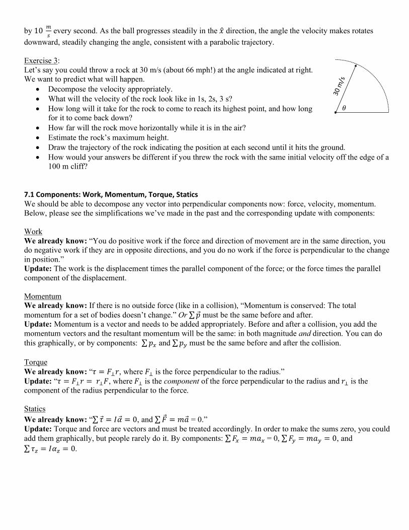
If we move 10 m horizontally in the +𝑥# direction, we don’t change our vertical position, and if we move 10 m upward in the +𝑦# direction, our horizontal position doesn’t change. If we were to move 10 m at a 45° angle above the horizontal, we might be tempted to think we move 5 m horizontally and 5 m vertically, but we can see that the 𝑥# and 𝑦#components of our displacement are clearly greater than 5 m, much closer to 7 m. We can express our displacement in 𝑥#, 𝑦# component form: ∆𝑥++++⃗ ~7𝑚𝑥# + 7𝑚𝑦# Similarly, if we moved in a direction that made a smaller angle, 𝜃, with the horizontal, we could see the horizontal displacement is very close to the full 10 m: ∆𝑥++++⃗ ~9.8𝑚𝑥# + 2𝑚𝑦# Exercise 1: Your boat is capable of a speed of 4 m/s with respect to the water and you aim your boat northward across a river 100 m wide that is flowing 3 m/s west.
• Draw what someone sees from a bridge far overhead. • What is the speed according to the person on the bridge? • What is your total displacement in your trip across the river? Please put your answer in terms of north and
west components. It turns out that forces decompose into perpendicular components the same way. If you were to pull on a string with a 10 N force in the direction of the diagram above, at an angle, 𝜃, with the horizontal. The force the string’s tension applies to the point of contact is the same as �⃗�~9.8𝑁𝑥# + 2𝑁𝑦#. Exercise 2: You are pulling a 10 kg sled on low friction ice by pulling an attached string with 40 N. Please make a good free body diagram for each of the following.
• If you pull directly upward, please find the resulting acceleration of the sled and 𝐹7 provided by the underlying ice on the sled.
• If you pull in the 𝑥# direction, please find the resulting acceleration of the sled and 𝐹7 provided by the underlying ice on the sled.
• If you pull at an angle as indicated in the diagram, please find the resulting acceleration of the sled and 𝐹7 provided by the underlying ice on the sled.
• If you pull at the smaller angle, 𝜃 as in the above diagram, please find the resulting acceleration of the sled and 𝐹7 provided by the underlying ice on the sled.
How do we know to decompose the force in horizontal and vertical and not some other direction? Usually the direction of acceleration determines the way you break a force vector into perpendicular components. In the above example, the sled is accelerating in the 𝑥# direction, so we know the 𝑎# = 0 in the 𝑦# direction. Thus, 𝑥#-𝑦# is a good axis. We will see in the next section that if the surface is not horizontal, it is best to pick your directions according to the new direction of acceleration. You will see that when using the dynamics lens, it’s crucially important to identify the direction of acceleration in free body diagrams. Parabolic Trajectory Throw a ball upward at an angle and watch its path from the side. You should notice that the ball traces a parabola. We can understand this by looking at the components of velocity. Once the ball leaves your hand, how many forces are acting on it, neglecting air friction? The only force, gravity, is downward so 𝑎; = 0, and 𝑎< = −𝑔. Thus, we should decompose the velocity into 𝑥# and 𝑦# components, knowing that 𝑣; is constant, and 𝑣< decreases
~9.8m~2m !
~7m
~7m
~3m45°
by 10AB
every second. As the ball progresses steadily in the 𝑥# direction, the angle the velocity makes rotates downward, steadily changing the angle, consistent with a parabolic trajectory. Exercise 3: Let’s say you could throw a rock at 30 m/s (about 66 mph!) at the angle indicated at right. We want to predict what will happen.
• Decompose the velocity appropriately. • What will the velocity of the rock look like in 1s, 2s, 3 s? • How long will it take for the rock to come to reach its highest point, and how long
for it to come back down? • How far will the rock move horizontally while it is in the air? • Estimate the rock’s maximum height. • Draw the trajectory of the rock indicating the position at each second until it hits the ground. • How would your answers be different if you threw the rock with the same initial velocity off the edge of a
100 m cliff? 7.1 Components: Work, Momentum, Torque, Statics We should be able to decompose any vector into perpendicular components now: force, velocity, momentum. Below, please see the simplifications we’ve made in the past and the corresponding update with components: Work We already know: “You do positive work if the force and direction of movement are in the same direction, you do negative work if they are in opposite directions, and you do no work if the force is perpendicular to the change in position.” Update: The work is the displacement times the parallel component of the force; or the force times the parallel component of the displacement. Momentum We already know: If there is no outside force (like in a collision), “Momentum is conserved: The total momentum for a set of bodies doesn’t change.” Or ∑𝑝 must be the same before and after. Update: Momentum is a vector and needs to be added appropriately. Before and after a collision, you add the momentum vectors and the resultant momentum will be the same: in both magnitude and direction. You can do this graphically, or by components: ∑𝑝; and ∑𝑝<must be the same before and after the collision. Torque We already know: “𝜏 = 𝐹7𝑟, where 𝐹7 is the force perpendicular to the radius.” Update: “𝜏 = 𝐹7𝑟 = 𝑟7𝐹, where 𝐹7 is the component of the force perpendicular to the radius and 𝑟7 is the component of the radius perpendicular to the force. Statics We already know: “∑𝜏 = 𝐼�⃗� = 0, and ∑ �⃗� = 𝑚�⃗� = 0.” Update: Torque and force are vectors and must be treated accordingly. In order to make the sums zero, you could add them graphically, but people rarely do it. By components: ∑𝐹; = 𝑚𝑎; = 0, ∑𝐹< = 𝑚𝑎< = 0, and ∑𝜏I = 𝐼𝛼I = 0.
!

Exercise 1: Starting from rest, you pull a 10 kg sled 10 m on low friction ice with a tension of 40 N oriented as shown in the picture.
• How much work did you do on the sled? What is the speed of the sled at the end of 10 m?
• If the ice actually had a coefficient of friction of 0.15, estimate the amount of thermal energy produced as you pull the sled 10 m. What is the speed at the end of the 10 m.
Exercise 2: The wheel you see at right is 1 m in diameter.
• Please rank the torques provided by each force from smallest torque to greatest torque.
• Please find the torque provided by each of the four forces. Exercise 3: A 10 kg ball at the end of a 3 m pole (free to pivot at its base) is supported by a cable attached 1 m from the pivot as shown at right.
• Please find the tension in the cable. • Please find the force the wall exerts on the pole, include direction.
Exercise 4: On a very slippery road, a 1000 kg car and a 2000 kg truck have a collision and stick to each other as shown at right
• Could the wreckage have gone off in this direction? How do you know?
• Estimate the general direction that the wreckage went after collision. • Find the final velocity of the wreckage immediately after the collision. • Find the impulse that the car received during the collision. • If the car crumpled about 1 m, argue that the amount of time for the collision should be about 1/15 of a
second. • Find the average force on the car during the collision.
7.2 Inclined Plane We already know how to analyze the motion of an object on an inclined plane by using an energy lens. If the plane is low friction, then ∆𝐸K = −∆𝐸Land we can find the final velocity. From the final velocity, we can find ∆𝑡 and acceleration as shown in the worked examples for section 6.0 systems. Exercise 1: A cart with low-friction, low-mass wheels rolls down an inclined plane that is 2 m long, as shown.
• From the drawing, please use an energy lens, estimating the initial height, and calculate 𝑣N
• Now can you calculate 𝑣OPQ , 𝑡, and 𝑎? • I stated that the wheels are low-mass. If a large portion of the cart’s mass was
in the wheels, how would your answer change?
car
Truck 20 m/s
10 N
30 N
30 N
20 N
a
b
c
d
!

We can also solve this problem with a dynamics/forces lens. Here it is crucial to identify the direction of the acceleration and make sure that when you add the forces, the resultant vector (�⃗�RQBSTUOVU = ∑ �⃗�) is in the same direction as the acceleration. At right, notice how you add the forces with different relative lengths if the object is accelerating down the incline (left) or if the forces result in horizontal acceleration (right). Horizontal acceleration can happen if the entire inclined surface accelerates to the left enough to keep the cart at the same elevation on the incline. Notice also that at left 𝑁 < 𝐹X, where at right 𝑁 > 𝐹X Exercise 2: Knowing that 𝐹X = 𝑚𝑔, estimate the other forces
• Please estimate �⃗�R and find the acceleration down the inclined plane.
• Please use geometry to prove that angle, 𝜃, labeled in my drawing is the same angle as in the original diagram.
• Consider how acceleration changes for both acceleration directions with an increase in the inclination angle, 𝜃.
Friction: What if the surface is not low friction? For dynamics, we need to add another force of friction oriented in the opposite direction of the velocity. Using the energy lens, we can include the work done by friction: 𝑊N ⟹ �⃗�N ∙ ∆�⃗�, that converts 𝐸L ⟹𝐸U] . Either way, we must calculate 𝐹N, which requires the normal force. Exercise 3: Estimate the acceleration if there is a coefficient of dynamic friction of 0.3.
• Use a dynamics lens. • Use an energy lens. • Do they provide compatible answers?
The conventional way to solve the inclined plane is by decomposing the forces into components parallel and perpendicular to acceleration; such that: ∑𝐹// = 𝑚𝑎//, and ∑𝐹7 = 𝑚𝑎7 = 0. For accelerating down the stationary inclined plane (left), we decompose �⃗�X, and for horizontal acceleration (right), we decompose the normal force. Exercise 4: Solve the problem again by decomposing �⃗�X into components perpendicular and parallel to the acceleration.
• Find the acceleration of the cart for the low friction case.
• Find the normal force. • With a coefficient of dynamic friction of 0.3, find
the acceleration. • Are your answers consistent with those found by the other methods?
Take Away Messages:
The relative lengths of the force vectors may not be correct in the top drawings. It is not until we identify the direction of acceleration and do the vector addition in the bottom drawings that we are able to determine their relative magnitudes.

• Always indicate the direction of acceleration, which dictates how you break up forces. • You can always use energy to solve an inclined plane, but if there’s friction involved, you will need to
include the work done by friction. 7.3 Conical Pendulum: The conical pendulum is “the tetherball problem” and likely gets its name because the string attached to the ball traces out the shape of a cone as the ball makes a circular path on the horizontal plane as shown at right. Using a dynamics lens: centripetal acceleration inward is caused by two forces: 𝐹X and the tension in the string. The sum of these forces, must be in the same direction as the acceleration: �⃗�RQBSTUOVU = ∑ �⃗� = 𝑚�⃗�. From the diagram at right, we see 𝑇 >𝐹X > `∑ �⃗�`. Thus, in the scenario above, if the ball is 1 kg and 𝐹X is 10 N, we might expect the tension to be about 12 N and the vector sum of the forces is about 6 N. Thus, the centripetal acceleration is about 6 m/s2. Exercise 1: For the above tetherball, draw the example that 𝜃 is much larger such that the string is close to horizontal. Show with a vector diagram how this would affect the tension in the string, the vector sum of the forces, and the acceleration. How would the speed of the ball compare to that in the diagram above? Be prepared to support your answer. Does your answer correlate with what you experience in the world? Exercise 2: For the above tetherball, consider the example that 𝜃 is much smaller such that the string is close to vertical. Show with a vector diagram how this would affect the tension in the string, the vector sum of the forces, and the acceleration. How would the speed of the ball compare to that in the diagram above? Be prepared to support your answer. Does your answer correlate with what you experience in the world? The ball on the string is only one of the four examples of the conical pendulum that you see in the world. The other three are:
1) car on a frictionless, banked turn, 2) an airplane banking into a turn, and 3) a bicyclist leaning into a turn.
For all of the examples, there is a downward force of gravity and one other force that keeps the object in equilibrium in the y-direction while providing an inward force that accelerates the object during uniform circular motion. Exercise 3: For a car and an airplane, the tension in the string is replaced by the normal force and lift, respectively. Please draw these scenarios and show how the force vector diagrams follow from the free body diagrams. Be careful that you pick the correct angle, and not its complement. Exercise 4: For the bicyclist, the tension in the string is replaced by the compressional force of the seat on the bicyclist’s body pushing in the direction of the bicycle frame. You can think of this as a normal force. Draw out this scenario and identify how the acceleration changes if the bicyclist leans further into a turn.
N
!⃗
lift
!⃗

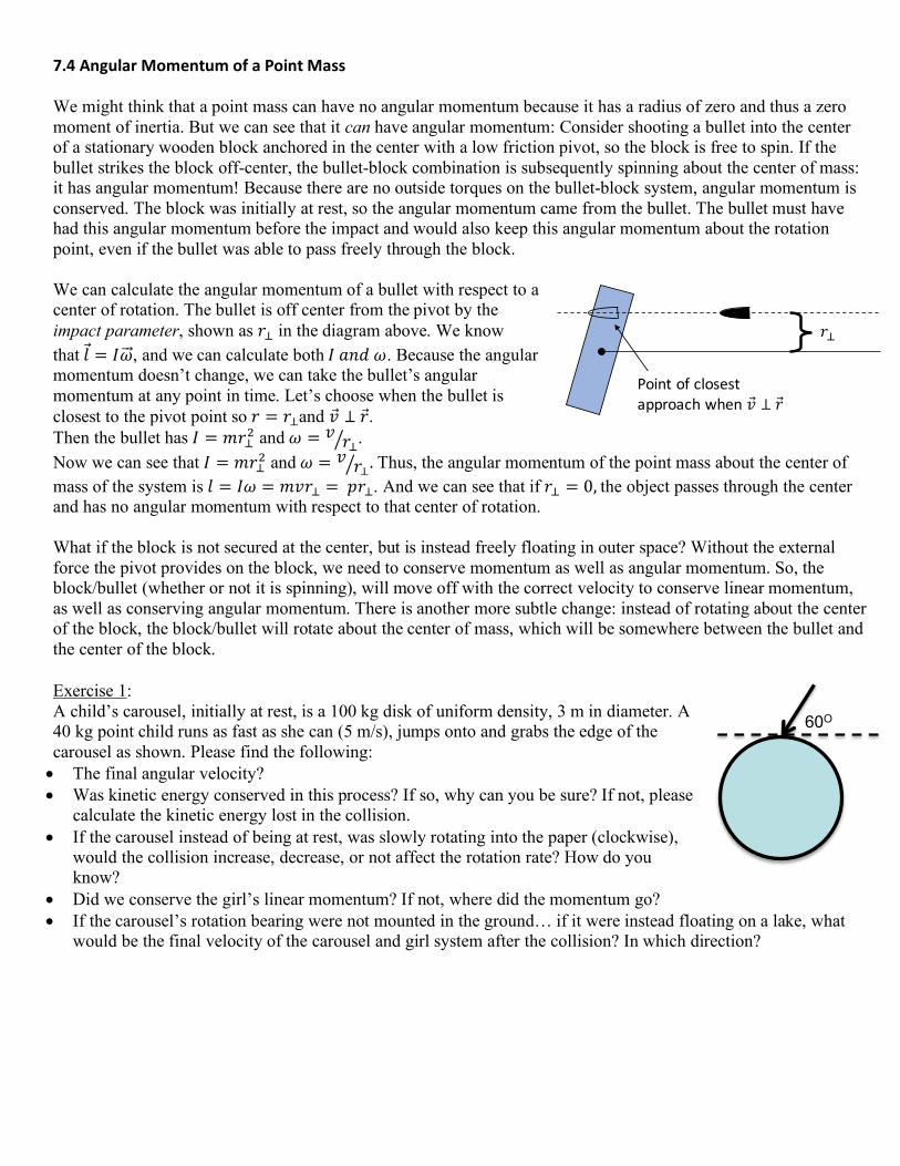
7.4 Angular Momentum of a Point Mass We might think that a point mass can have no angular momentum because it has a radius of zero and thus a zero moment of inertia. But we can see that it can have angular momentum: Consider shooting a bullet into the center of a stationary wooden block anchored in the center with a low friction pivot, so the block is free to spin. If the bullet strikes the block off-center, the bullet-block combination is subsequently spinning about the center of mass: it has angular momentum! Because there are no outside torques on the bullet-block system, angular momentum is conserved. The block was initially at rest, so the angular momentum came from the bullet. The bullet must have had this angular momentum before the impact and would also keep this angular momentum about the rotation point, even if the bullet was able to pass freely through the block. We can calculate the angular momentum of a bullet with respect to a center of rotation. The bullet is off center from the pivot by the impact parameter, shown as 𝑟7 in the diagram above. We know that𝑙 = 𝐼𝜔++⃗ , and we can calculate both𝐼𝑎𝑛𝑑𝜔. Because the angular momentum doesn’t change, we can take the bullet’s angular momentum at any point in time. Let’s choose when the bullet is closest to the pivot point so 𝑟 = 𝑟7and 𝑣 ⊥ 𝑟. Then the bullet has 𝐼 = 𝑚𝑟7f and𝜔 = 𝑣 𝑟7g . Now we can see that 𝐼 = 𝑚𝑟7f and𝜔 = 𝑣 𝑟7g . Thus, the angular momentum of the point mass about the center of mass of the system is 𝑙 = 𝐼𝜔 = 𝑚𝑣𝑟7 = 𝑝𝑟7. And we can see that if 𝑟7 = 0,the object passes through the center and has no angular momentum with respect to that center of rotation. What if the block is not secured at the center, but is instead freely floating in outer space? Without the external force the pivot provides on the block, we need to conserve momentum as well as angular momentum. So, the block/bullet (whether or not it is spinning), will move off with the correct velocity to conserve linear momentum, as well as conserving angular momentum. There is another more subtle change: instead of rotating about the center of the block, the block/bullet will rotate about the center of mass, which will be somewhere between the bullet and the center of the block. Exercise 1: A child’s carousel, initially at rest, is a 100 kg disk of uniform density, 3 m in diameter. A 40 kg point child runs as fast as she can (5 m/s), jumps onto and grabs the edge of the carousel as shown. Please find the following: • The final angular velocity? • Was kinetic energy conserved in this process? If so, why can you be sure? If not, please
calculate the kinetic energy lost in the collision. • If the carousel instead of being at rest, was slowly rotating into the paper (clockwise),
would the collision increase, decrease, or not affect the rotation rate? How do you know?
• Did we conserve the girl’s linear momentum? If not, where did the momentum go? • If the carousel’s rotation bearing were not mounted in the ground… if it were instead floating on a lake, what
would be the final velocity of the carousel and girl system after the collision? In which direction?
60O
!"
Pointofclosestapproachwhen#⃗ ⊥ !⃗
7.5 Angular Momentum, Stability, Precession If you want to change a body’s momentum, you apply a force; either linearly or rotationally: Linear Rotation
∑�⃗� = hi⃗hU
∑𝜏 = hT⃗hU
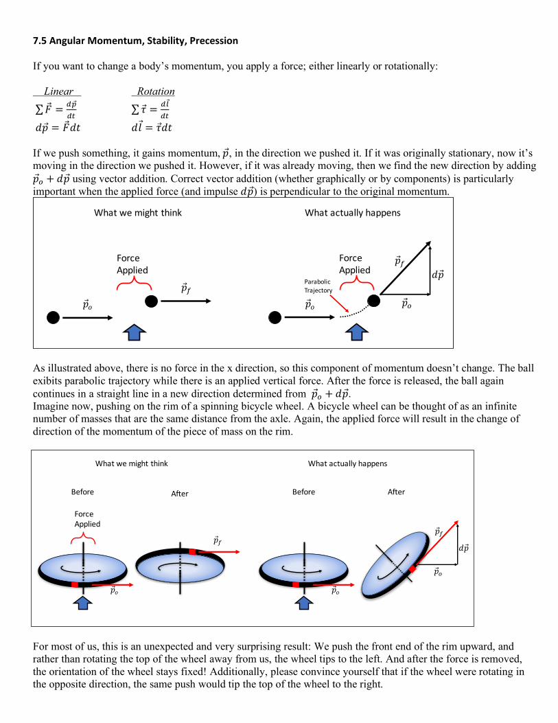
𝑑𝑝 = �⃗�𝑑𝑡 𝑑𝑙 = 𝜏𝑑𝑡 If we push something, it gains momentum,𝑝, in the direction we pushed it. If it was originally stationary, now it’s moving in the direction we pushed it. However, if it was already moving, then we find the new direction by adding 𝑝j + 𝑑𝑝 using vector addition. Correct vector addition (whether graphically or by components) is particularly important when the applied force (and impulse 𝑑𝑝) is perpendicular to the original momentum.
As illustrated above, there is no force in the x direction, so this component of momentum doesn’t change. The ball exibits parabolic trajectory while there is an applied vertical force. After the force is released, the ball again continues in a straight line in a new direction determined from 𝑝j + 𝑑𝑝. Imagine now, pushing on the rim of a spinning bicycle wheel. A bicycle wheel can be thought of as an infinite number of masses that are the same distance from the axle. Again, the applied force will result in the change of direction of the momentum of the piece of mass on the rim.
For most of us, this is an unexpected and very surprising result: We push the front end of the rim upward, and rather than rotating the top of the wheel away from us, the wheel tips to the left. And after the force is removed, the orientation of the wheel stays fixed! Additionally, please convince yourself that if the wheel were rotating in the opposite direction, the same push would tip the top of the wheel to the right.
!⃗#
ForceApplied
!⃗$!⃗#
ForceApplied
!⃗%
&!⃗!⃗$
ParabolicTrajectory
Whatwemightthink Whatactuallyhappens
!⃗#
!⃗$
%!⃗!⃗#
Whatwemightthink Whatactuallyhappens
After
!⃗&
ForceApplied
Before
!⃗&
Before After
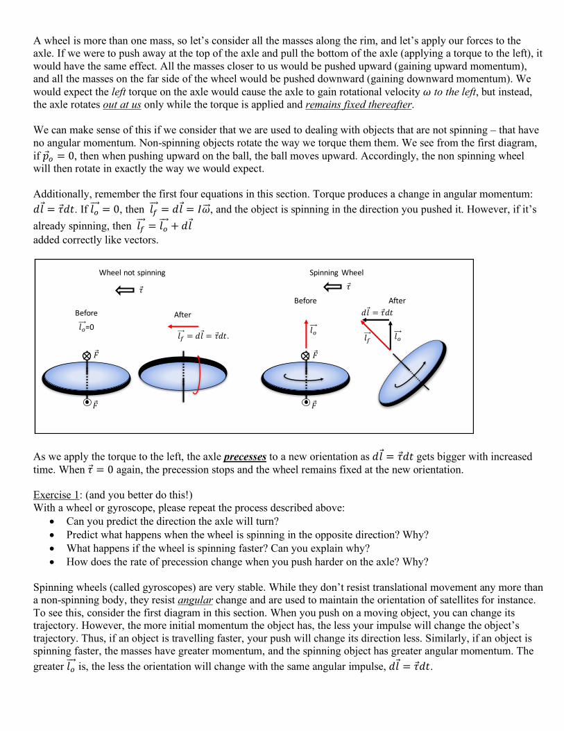
A wheel is more than one mass, so let’s consider all the masses along the rim, and let’s apply our forces to the axle. If we were to push away at the top of the axle and pull the bottom of the axle (applying a torque to the left), it would have the same effect. All the masses closer to us would be pushed upward (gaining upward momentum), and all the masses on the far side of the wheel would be pushed downward (gaining downward momentum). We would expect the left torque on the axle would cause the axle to gain rotational velocity 𝜔 to the left, but instead, the axle rotates out at us only while the torque is applied and remains fixed thereafter. We can make sense of this if we consider that we are used to dealing with objects that are not spinning – that have no angular momentum. Non-spinning objects rotate the way we torque them them. We see from the first diagram, if 𝑝j = 0, then when pushing upward on the ball, the ball moves upward. Accordingly, the non spinning wheel will then rotate in exactly the way we would expect. Additionally, remember the first four equations in this section. Torque produces a change in angular momentum: 𝑑𝑙 = 𝜏𝑑𝑡. If 𝑙j+++⃗ = 0, then 𝑙N++⃗ = 𝑑𝑙 = 𝐼𝜔++⃗ , and the object is spinning in the direction you pushed it. However, if it’s already spinning, then 𝑙N++⃗ = 𝑙j+++⃗ + 𝑑𝑙 added correctly like vectors.
As we apply the torque to the left, the axle precesses to a new orientation as 𝑑𝑙 = 𝜏𝑑𝑡 gets bigger with increased time. When 𝜏 = 0 again, the precession stops and the wheel remains fixed at the new orientation. Exercise 1: (and you better do this!) With a wheel or gyroscope, please repeat the process described above:
• Can you predict the direction the axle will turn? • Predict what happens when the wheel is spinning in the opposite direction? Why? • What happens if the wheel is spinning faster? Can you explain why? • How does the rate of precession change when you push harder on the axle? Why?
Spinning wheels (called gyroscopes) are very stable. While they don’t resist translational movement any more than a non-spinning body, they resist angular change and are used to maintain the orientation of satellites for instance. To see this, consider the first diagram in this section. When you push on a moving object, you can change its trajectory. However, the more initial momentum the object has, the less your impulse will change the object’s trajectory. Thus, if an object is travelling faster, your push will change its direction less. Similarly, if an object is spinning faster, the masses have greater momentum, and the spinning object has greater angular momentum. The greater 𝑙j+++⃗ is, the less the orientation will change with the same angular impulse, 𝑑𝑙 = 𝜏𝑑𝑡.
Wheelnotspinning SpinningWheel
AfterBeforeBefore After
!⃗
#$=0
%⃗
!⃗
#& = (#⃗ = %⃗().
!⃗
!⃗
#$ #$
(#⃗ = %⃗()
#&
%⃗

Exercise 2: Please answer the following questions:
• Why do we spin a Frisbee (or football) when we throw it? • Please notice sometime that the rim of the Frisbee is very thick. Why do you think that they are made this
way? Gravitational precession of a gyroscope or top. If the axle of a spinning wheel, top, or gyroscope is not vertical and is supported only on once side, then gravity provides a constant torque perpendicular to the axis orientation. This torque produces a constant supply of changes of angular momentum: 𝑑𝑙 = 𝜏𝑑𝑡. Again, we might think that this would cause the axle to rotate downward. However, 𝑑𝑙 is added to the present angular momentum of the spinning wheel, and the axle instead precesses in a circle in the horizontal plane. Please verify this from the diagrams at below.
Exercise 3: Spin a wheel or a gyroscope, support it from one side of the axle, and verify the behavior of the precession.
• Can you predict what will happen? • What changes if you spin the wheel the other way?
Why? • What changes if you spin the wheel faster? Why? • What changes if you switch sides and support the axle
on the other side? Why? • What happens if you support the axle closer to the
center of the wheel? Why? 7.6 Trigonometry and Two Derived Equations Here are two kinematics equations that you can use to expedite a kinematics answer. I don’t find them helpful for the following reasons:
• They only pertain to situations for constant acceleration. • Many students use them for the wrong situation without using the correct “lens”.
If you are going to use them, verify that you have straight line constant acceleration and you are very careful of the signs:
SpinningWheelHangingonaStringt0
!"
#$
%⃗, (#
TstringTstring
t1Tstringt2
#$%⃗, (#
Tstringt3 t4
!"
#$
%⃗, (#
Tstring
LookingDownwardonSpinningWheelHangingonaStringt0
!"#$%#
Tstring
!"#&
Tstring
t1
#& fornextmoment #'
(⃗
%#
(⃗

𝑥(𝑡) = 𝑥m + 𝑣m𝑡 +nf𝑎𝑡f
2𝑎∆𝑥 = 𝑣Nf − 𝑣mf
Exercise 1: Let’s derive the first of these equations three ways:
• We know that 𝑥(𝑡) = 𝑥m + ∆𝑥, and that ∆𝑥 is the area under the 𝑣 − 𝑡 graph. Make a 𝑣 − 𝑡 graph for constant acceleration, remembering how we show constant acceleration on a 𝑣 − 𝑡 graph. Find a formula that expresses the area under the curve in terms of 𝑣m, 𝑎, and 𝑡, and substitute it in for ∆𝑥.
• We know that displacement is the integral of velocity. Please integrate the expression for velocity as a function of time and constant acceleration. In all integrations, you will need to add a constant using a boundary condition. Make your boundary condition 𝑥(Uom) = 𝑥m.
• We have two equations for average velocity: 𝑣OPQ =
∆;∆U
, for all scenarios, and ∆𝑡 is the same as t in most kinematic equations; and
𝑣OPQ =nf(𝑣m + 𝑣N) , only for constant acceleration
Use these equations to express 𝑥(𝑡) = 𝑥m + ∆𝑥, using only 𝑥(𝑡) = 𝑥m, 𝑣m, 𝑎, and 𝑡. Exercise 2: Let’s derive the second equation two ways:
• Use an energy lens looking at a moving object. Apply a force to the object parallel to the direction of the velocity (either speeding it up or slowing it down). Set up an equation indicating that the work your force does is the change in the object’s kinetic energy.
• Use the following two equations to eliminate time: 𝑥(𝑡) = 𝑥m + 𝑣m𝑡 + p
q𝑎𝑡f
𝑣N = 𝑣m + 𝑎𝑡 There is a class of kinematic problems that these equations facilitate. Below are two. Exercise 3: I throw a rock upward from the top of a 100 m cliff at a velocity of 30 m/s.
• When does the rock hit the ground? • If you used our new equation, you likely solved a quadratic equation and got two answers, one positive and
one negative. What is the relevance of the negative answer? Exercise 4: Solve the notorious “catching the bus” problem. The bus is at your stop, and you’re running at a constant speed of 7 m/s from behind in order to catch it. However, just when you’re 20 m behind it (or behind the bus driver to be exact), the bus begins accelerating away from you at 1 m/s2, and will continue accelerating at 1 m/s2 unless you can meet eyes with the driver.
• Do you catch the bus? If so, at what time? If not, how close do you come? “Catching the bus” means that the difference in your displacement and that of the bus is zero. You will likely have to solve a quadratic equation for this. Real answers indicate it happens.
• For the above problem, what would be the physical relevance of two correct answers? • Draw the displacement – time, and velocity – time graphs. Graph yourself and the bus on each graph. • Repeat the above problem with the difference that the bus starts when you are 30 m behind it.

Trigonometry We have tabulated ratios of sides for right triangles with the corresponding angles. It follows:
𝑠𝑖𝑛𝜃 =𝑜𝑝𝑝𝑜𝑠𝑖𝑡𝑒
ℎ𝑦𝑝𝑜𝑡𝑒𝑛𝑢𝑠𝑒
𝑐𝑜𝑠𝜃 =𝑎𝑑𝑗𝑎𝑐𝑒𝑛𝑡ℎ𝑦𝑝𝑜𝑡𝑒𝑛𝑢𝑠𝑒
𝑇𝑎𝑛𝜃 =𝑜𝑝𝑝𝑜𝑠𝑖𝑡𝑒𝑎𝑑𝑗𝑎𝑐𝑒𝑛𝑡
Trigonometry is necessary in order to have greater than 10% precision in your answer. However, please heed this warning: Physics formulas that have trigonometry functions in them do not tell you which angle to use. For instance, Work is often defined as: 𝑊 = �⃗� ∙ �⃗� = 𝐹𝑥(𝑐𝑜𝑠𝜃), but you don’t know which of the two acute angles in the triangle you will be given. It may be more effective instead to just remember: 𝑊 = 𝐹//𝑥 and use trigonometry to find the parallel component of the force. Exercise 5: I pull a 10 kg sled 5 m with a 40 N tension at an angle of 30° with respect to the vertical as shown.
• Find the amount of work I do. • If there is a coefficient of friction of 0.15, please find the acceleration of the sled.
Exercise 6: You hit a baseball at a 20 degree angle above the horizon, at an initial velocity of 20 m/s off the edge of a cliff 50 m high, we would like to know everything about the future of this ball. Ignore air friction. Please solve this two ways, and tell me which you like best:
• Using an energy lens, please find the final speed of the ball. I don’t have to tell you to start with a good drawing, right?
• Assert what you know about the horizontal component of the ball’s velocity throughout its flight, and why you know this. Then, use this information to find the ball’s vertical velocity and the angle it makes with the horizon just before hitting the ground.
• Knowing the initial and final vertical velocities, find the amount of time the ball is in the air, and then the horizontal distance the ball went before landing.
Then solve the above problem using kinematics, which is the way it’s usually done: • Please separate the problem into two parts, the horizontal and the vertical. You are looking for the
horizontal displacement. However, you need to know how long the ball is in the air. Please solve the vertical part to find out how long it is in the air. Which lens will be most useful to find time?
• Then you can use this time to find the distance that the ball has moved horizontally. Please show all your work and carefully carry and cancel units.
• Find the final velocity (magnitude and direction), of the ball immediately before it hits the ground.
Which approach do you like best? Exercise 7: Find the torque provided by forces d and c, given this is a wheel with a 3 m diameter.
!Adjacent
Opp
osite
!
30°
30O
30O
10 N
30 N
30 N
20 N
a
b
c
d