7. subject details 7.5 switchgear and · pdf filenot covered. unit-viii power system...
TRANSCRIPT

7. SUBJECT DETAILS
7.5 SWITCHGEAR AND PROTECTION
7.5.1 Objective and Relevance
7.5.2 Scope
7.5.3 Prerequisites
7.5.4 Syllabus
i. JNTU
ii. GATE
iii. IES
7.5.5 Suggested Books
7.5.6 Websites
7.5.7 Experts’ Details
7.5.8 Journals
7.5.9 Finding and Developments
7.5.10 Session Plan
i. Theory
ii. Tutorial
7.5.11 Student Seminar Topics
7.5.12 Question Bank
i. JNTU
ii. GATE
iii. IES

7.5.1 OBJECTIVE AND RELEVANCE
Now a days interconnected Power System Operation is complex and vary in sizes and configurations. The
technical analysis of transmission line is done to know its performance. An Electric Power System consists
of large equipment like generators, transformers and associated transmission and distribution network.
Short circuits and other abnormal conditions often occur on a power system which leads to heavy faults
resulting damage of the power apparatus. Hence it is mandatory for an Electrical Engineer to be aware of
impartance and operation of switch gear and protection.
This course introduces all varieties of circuit breakers and relays for protection of generators, transformers
and feeder, bus bars from over voltages and other hazards. It emphasis on Neutral grounding for overall
protection.
7.5.2 SCOPE
This subject provides the knowledge on switchgear and protection of various power system
elements. This leads to the understanding of how a power plant or electric substation can
be maintained for smooth functioning. It also makes one to know about protection of
various elements from both internal faults like earth fault, short circuit faults etc. a nd
external faults like lightning faults.
7.5.3 PREREQUISITES
It requires knowledge of Power systems, Network theory, Electrical machines, Prime
movers, electrical and mechanical design of transmission lines and applied mathematics.
7.5.4 JNTU SYLLABUS
UNIT-I
OBJECTIVE Explains the elementary principles of restriking and recovery voltages and arc
extinguishing phenomenons.
SYLLABUS
CIRCUIT BREAKERS-I: Elementary principles of arc interruption, restriking and recovery voltages, restriking
phenomenon, average and max. RRRV, numerical problems. Current chopping and
resistance switching. CB ratings and specifications: Types and numerical problems, auto
reclosures.
UNIT-II
OBJECTIVE This unit is meant for explaining different types of circuit breakers.
SYLLABUS
CIRCUIT BREAKERS-II: Description and operation of following types of circuit breakers: Minimum oil circuit
breakers, Air blast circuit breakers, Vacuum and SF6 circuit breakers.
UNIT-III
OBJECTIVE This unit on “Electromagnetic and static relays” gives the details of both electromagnetic
and static relays and their necessity, principle of operation and construction

SYLLABUS
ELECTROMAGNETIC AND STATIC RELAYS: Principle of operation and construction of attracted armature, balanced beam, induction
disc and induction cup relays.
Relays classification: Instantaneous, DMT and IDMT types.
Application of relays: Over current/under voltage relays, direction relays, differential
relays and percentage differential relays.
Universal torque equation, Distance relays: impedance, reactance and Mho and Off -set
Mho relays, characteristics of distance relays and comparision.
Static relays: Static relays verses electromagnetic relays.
UNIT-IV
OBJECTIVE This unit explains about protection of generators against various types of faults.
SYLLABUS
GENERATOR PROTECTION: Protection of generators against stator faults, rotor faults, and abnormal conditions.
Restricted earth fault and inter -turn fault protection, numerical problems % win ding
unprotected.
UNIT-V
OBJECTIVE This unit explains about protection of transformer against various types of faults.
SYLLABUS
TRANSFORMER PROTECTION: Protection of transformers: Percentage differential protection, numerical problem on
design of CTs Ratio, Buchholtz relay protection.
UNIT-VI
OBJECTIVE This unit explains about protection of Feeder and busbars against various types of faults
and type of relay protection used.
SYLLABUS
FEEDER AND BUS-BAR PROTECTION: Protection of lines: Over current, carrier current and three zone distance relay protection
using impedance relays. Translay relay.
Protection of bus bars, differential protection.
UNIT-VII
OBJECTIVE This unit explains different types of grounding adopted in practice.
SYLLABUS
NEUTRAL GROUNDING: Grounded and ungrounded neutral systems. Effects of ungrounded neutral on system
performance. Methods of neutral grounding: Solid, resistance, reactance, arcing grounds
and grounding practices.
UNIT-VIII
OBJECTIVE This unit explains protection against over voltages and insulation coordination required
for this protection and over voltage phenomenons.

SYLLABUS
PROTECTION AGAINST OVER VOLTAGES: Generation of over voltages in power systems. Protection against lightning over voltages, valve type and
Zinc-oxide lighting arresters. Insulation and coordination, BIL, impulse ratio, standard impulse test wave,
volt-time characteristics.
7.5.3.2 GATE SYLLABUS
UNIT-I Circuit breakers.
UNIT-II
Circuit breakers.
UNIT-III
Solid state relays, over current, differential and distance protection.
UNIT-IV Differential protection.
UNIT-V Differential protection.
UNIT-VI Over current protection, distance and differential protection.
UNIT-VII Not covered.
UNIT-VIII Insulation.
7.5.3.3 IES SYLLABUS
UNIT-I Power system protection, circuit breakers.
UNIT-II
Power system protection, circuit breakers.
UNIT-III
Relays.
UNIT-IV
Power system protection.
UNIT-V Power system protection.
UNIT-VI Power system protection.
UNIT-VII

Not covered.
UNIT-VIII Power system transients.
7.5.5 SUGGESTED BOOKS
TEXT BOOKS
T1 Switchgear and Protection, Sunil S. Rao, Khanna Publishers.
T2 Power System Protection and Switch Gear, Badari Ram, D.N Viswakarm a, TMH
Publications
REFERENCE BOOKS
R1 Fundamentals of Power System Protection, Paithankar and S.R.Bhide.,PHI, 2003.
R2 Power system protection and switchgear, Bhuvnesh Oza, TMH, 2010.
R3 Electrical Power Systems, C.L.Wadhwa, 2 n d Edn.,New Age International (P) Limited.
R4 Principles of Power Systems, V.K. Mehta, Rohit Mehta, S.Chand and Co.
R5 Hand Book of Switchgears, BHEL, TMH Publications.
R6 Power System Protection and Switchgear, Ravindranth & Chander, New Age International
(P) Ltd.
7.5.6 WEBSITES
1. www.ntu.ac.sg
2. www.utoronto.ca
3. www.ee.washington.edu
4. www.esca.com
5. www.ne.ac.sg
6. www.iitb.ac.in
7. www.annauniv.edu
8. www.ieeecss.org
9. www.ieee.com
10. www.iee.com
11. www.etinstrumentat ion.com
7.5.7 EXPERTS’ DETAILS
INTERNATIONAL 1. Mr. M. Karimi-Ghartemani
Centre for Applied Power Electronics (CAPE)
Department of Electrical and Computer Engineering,
University of Toronto,
Toronto, ON M5S 3GL, Canada.
email: [email protected]
2. Mr. M.R.Iravani
Centre for Applied Power Electronics (CAPE)
Department of Electrical and Computer Engineering,
University of Toronto,
Toronto, ON M5S 3GL, Canada.
email: [email protected]

NATIONAL 1. Dr. D. N. Vishwakarma
Professor
Department of Electrical Engineering
Institute of Technology, BHU
email:[email protected]
2. Dr Majid Jamil
Professor
Department of Electrical Engineering,
Faculty of Engineering & Technology,
Jamia Millia Islamia,
New Delhi - 110025
[email protected], [email protected]
REGIONAL 1. Dr. M. Surya Kalavathi,
Dept. of EEE,
JNTU College of Engg.,
Kukatpally, Hyderabad.
email: [email protected]
2. Mr. Hanumantha Rao
Dy. Gen. Manager,
Transmission Systems,
BHEL, R&D, Hyderabad.
Andhra Pradesh.
7.5.8 JOURNALS
INTERNATIONAL 1. IEEE Transactions on Power Systems
2. IEEE Transactions on Power Delivery
3. IEEE Transactions on Energy Conversion
4. Institution of Electrical Engineers
NATIONAL 1. Institution of Engineers (India)
2. System Society of India
7.5.9 FINDINGS AND DEVELOPMENTS
1. Study of solving coordination curve intersection of inverse -time over current relays in
subtransmission systems, J.L. Cheng and Y . Lu, W.S. Kao, Vol. 23, No. 4, IEEE
Transactions on Power Delivery, October 2008.
2. Combined wavelet - SVM Technique for fault zone detection in a series compensated
transmission line, U.B. Parikh, B. Das, R.P. Maheswari, Vol.23,No.4, IEEE Transactions
on Power Delivery, Oct.2008.
3. A distance protection relay for a 100kv UHV transmission line, Z.Y. Xu, S.F. Huang & L.
Ran, Vol. 23, No. 4, IEEE Transactions on Power Delivery, October 2008.
4. Enhanced numerical breaker failure protection, B. Kaszten ny, V. Muthukrishnan, T.S.
Sidhu, Vol. 23, No. 4, IEEE Transactions on Power Delivery, October 2008.
5. A new strategy for determining fault zones in distance relays, M. Gilany and Y. Madouh,
Vol.23, No.4, IEEE Transactions on Power Delivery, October 20 08.

7.5.10 SESSION PLAN
i. THEORY
Sl.
No. Topics in JNTU Syllabus Modules and Sub modules
Lecture
No. Suggested Books
Remarks
UNIT-I (CIRCUIT BREAKERS-1)
1 Switchgear and
Protection
Objective and relevance
Overview of the subject
Introduction
Prerequisites
Scope of the subject
Present scenario of Power
System Protection
L1
L2
2 Circuit breakers Sub station equipment
Faults and abnormal conditions
Fault clearing process
Some terms in the test
Significance of switchgear and
protection
L3 T1-Ch1, T2-Ch9
R1-Ch1, R3-Ch15
R4-Ch19, R5-Ch1
R6-Ch13
GATE
IES
3 Elementary principles of
arc interruption
Electric arc
Initiation of the arc
High resistance arc interruption
Current zero interruption
- Slepain’s theory
- Energy balance theory
L4
L5
T1-Ch4, T2-Ch9
R3-Ch15,
R4-Ch19,R5-Ch1
R6-Ch13
GATE
IES
4 Restriking and recovery
voltages
Restriking
phenomenon, average
and max. RRRV
Expression for restricting and
recovery voltages
Average RRRV
Maximum RRRV
L6
L7
T1-Ch3, T2-Ch9
R3-Ch15,
R4-Ch19,R6-Ch14
GATE
IES

5 Numerical Problems. Problems on restriking and
recovery voltages
L8
L9
T1-Ch3, T2-Ch9
R3-Ch15,
R4-Ch19,R6-Ch14
GATE
IES
6 Current chopping and
resistance switching
Circuit analysis
Interruption of capacitive
currents
L10 T1-Ch3, T2-Ch9
R3-Ch15,
R4-Ch19,R6-Ch14
GATE
IES
6 CB ratings and
specifications: types
Braking capacity
Short time current rating
Rated voltage, current and
frequency
Rated operating duty
Rated making capacity
L11 T1-Ch3, T2-Ch9
R3-Ch15,
R4-Ch19,R6-Ch14
GATE
IES
7 Numerical problems Problems on CB ratings L12 T1-Ch3, T2-Ch9
R3-Ch15,
R4-Ch19,R6-Ch14
GATE
IES
8 Auto enclosures Auto enclosures L13 T1-Ch2, T2-Ch4
R3-Ch15,
R4-Ch19,R5-Ch6
R6-Ch7
GATE
IES
UNIT-II (CIRCUIT BREAKERS-2)
9 Description and
operation of following
types of circuit
breakers
Minimum oil circuit
breakers
Introduction
Description and operation of
minimum oil circuit breakers
L14 T1-Ch8, T2-Ch9
R3-Ch15,
R4-Ch19,R5-Ch1
R6-Ch15
GATE
IES
10 Air blast circuit
breakers
Construction and operation
Principle of arc quenching
Cross blast and axial blast circuit
L15 T1-Ch6, T2-Ch9
R3-Ch15,
R4-Ch19,R5-Ch1
GATE
IES

breakers R6-Ch15
11 Vacuum circuit
breakers.
The vacuum arc
Current chopping
The vacuum arc recovery
Construction of VB
Applications
L16 T1-Ch9, T2-Ch9
R3-Ch15,
R4-Ch19,R5-Ch1
R6-Ch16
GATE
IES
12 SF6 circuit breakers Properties of SF6 gas
Different types of SF6 circuit
breakers
Construction and operation of
SF6 circuit breakers
L15 T1-Ch7, T2-Ch9
R3-Ch15, R5-Ch1
GATE
IES
Merits and demerits
Applications
L16 T1-Ch7, T2-Ch9
R3-Ch15, R5-Ch1
GATE
IES
UNIT-III (ELECTROMAGNETIC AND STATIC RELAYS)
13 Principle of operation
and construction
ofattracted armature
and balanced beam
relays
Relays introduction
Some definitions
Relay types
Operating principles
L17 T1-Ch25, T2-Ch2
R3-Ch14, R5-Ch9
GATE
IES
Construction and operation of
attracted armature and balanced
beam relays
Time-current characteristics
Types
Applications
L18
L19
T1-Ch26, T2-Ch2
R3-Ch14, R5-Ch9
GATE
IES
14 Induction disc and
induction cup relays
Construction and operation of
induction disc relay
Shaded pole and watt-hour
meter types
Torque equation
L20 T1-Ch26, T2-Ch2
R3-Ch14, R5-Ch9
GATE
IES

Plug setting and time setting
Operation and construction of
induction cup relays
L21 T1-Ch26, T2-Ch2
R3-Ch14
GATE
IES
15 Relays classification:
Instantaneous, DMT
and IDMT types.
Time current characteristics
Plug Setting Multiplier
Problems on Plug Setting
Multiplier
L22 T1-Ch27, T2-Ch3
R3-Ch14, R1-Ch2
GATE
IES
16 Application of relays:
Over current/under
voltage relays,
direction relays
Construction
Phasor diagrams
Torque equation
Applications
L23 T1-Ch26,27 T2-Ch3
R3-Ch14, R1-Ch2
GATE
IES
17 Differential relays Principle of operation
Principle of circulating current
differential protection
Difficulties
Applications
L24 T1-Ch28, R3-Ch14 GATE
IES
18 Percentage differential
relays
Operating characteristics
Applications
L25 T1-Ch28, R3-Ch14 GATE
IES
19 Universal torque
equation
Distance relays:
Impedance relay
Introduction
Principle of R-X diagram
Operating characteristics
L26 T1-Ch29, T2-Ch4
R1-Ch6, R3-Ch14
GATE
IES
20 Reactance relay Torque equation
Characteristics
L27 T1-Ch29, T2-Ch4
R1-Ch6, R3-Ch14
GATE
IES
21 Mho and Off-set Mho
relays
Torque equation
Characteristics
L28 T1-Ch29, T2-Ch4
R1-Ch6, R3-Ch14
GATE
IES
22 Characteristics of
distance relays and
comparison
Characteristics of distance relays
and comparison
L29 T1-Ch29, T2-Ch4
R1-Ch6, R3-Ch14
GATE
IES

23 Static relays: Static
relays verses
electromagnetic relays
Introduction to static relays
General theory of operation
Comparison
L30 T1-Ch38, T2-Ch4
R2-Ch1, R3-Ch14
R5-Ch9
GATE
IES
Problems on relays L31 T1-Ch28, T2-Ch4
R3-Ch14
GATE
IES
UNIT-IV (GENERATOR PROTECTION)
24 Protection of
generators against
stator faults, Rotor
faults
Introduction
Stator protection
- Differential protection
- Percentage differential
protection
- Stator over heating protection
L32 T1-Ch33, T2-Ch6
R1-Ch8, R3-Ch14
GATE
IES
Rotor protection
- Field ground fault protection
- Protection against rotor over
heating
L33 T1-Ch33, T2-Ch6
R1-Ch8, R3-Ch14
GATE
IES
25 Abnormal conditions Un-balanced loading
Over loading
Over speed
Over voltage
Failure of the prime mover
Loss of excitation
L34 T1-Ch33, T2-Ch6
R1-Ch8, R3-Ch14
GATE
IES
26 Restricted earth fault
and inter-turn fault
protection
Transverse differential
protection
Inter turn protection based on
zero sequence component
L35
T1-Ch33, T2-Ch6
R3-Ch14
GATE
IES
27 Numerical problems
on % winding
Numerical problems on %
winding unprotected.
L36 T1-Ch33, T2-Ch6 GATE

unprotected. L37 R3-Ch14 IES
Revision on the topics of I-IV units L
UNIT-V (TRANSFORMER PROTECTION)
28 Protection of
transformers:
Percentage differential
protection
Types of faults
Percentage differential
protection for Star-Delta
transformer
Grounded and ungrounded
transformer protection
L38 T1-Ch32,T2-Ch6
R1-Ch4, R3-Ch14
R5-Ch3
GATE
IES
Biased differential protection
Earth fault protection
L39 T1-Ch32,T2-Ch6
R3-Ch14
GATE
IES
29 Numericalproblems on
design of CT s ratio
Problems on CT ratio L40
L41
T1-Ch32, R3-Ch14 GATE
IES
30 Buchholtz relay
protection
Principle
Arrangements
Installation
Limitations
L42 T1-Ch32,T2-Ch6
R1-Ch4, R3-Ch14
GATE
IES
UNIT-VI (FEEDER AND BUS-BAR PROTECTION)
31 Protection of lines:
Over current
protection
Time graded system
Current graded system
Time current graded system
L43 T1-Ch34, T2-Ch6
R1-Ch2, R3-Ch14
R5-Ch3
GATE
Protection of parallel feeders
Protection of ring mains
L44 T1-Ch34, T2-Ch6
R3-Ch14, R5-Ch3
GATE
32 Carrier current
protection
Block diagram
Phase comparison scheme
L45 T1-Ch30, T2-Ch5
R1-Ch7, R3-Ch14
33 Three-zonedistance
relay protection using
impedance relays
Impedance characteristics for
three-zone protection
Contact circuit of three-zone
L46 T1-Ch34, T2-Ch6
R1-Ch6, R3-Ch14
GATE

impedance relay
34 Translay relay
protection of bus bars:
differential protection
Bus zone protection by
differential principle
Single line diagram
L47
L48
T1-Ch34, T2-Ch5,6
R1-Ch5, R3-Ch14
GATE
UNIT-VII (NEUTRAL GROUNDING)
35 Grounded and
ungrounded neutral
systems.Effects of
ungrounded Neutral
on
system performance
Introduction
Terms and definitions
Effectively grounded system
Ungrounded system and
Resonant grounding
Problems on various groundings
L49 T1-Ch18b, R3-Ch11
36 Methods of neutral
grounding: Solid,
resistance, reactance,
arcing grounds and
grounding practices
Advantages of neutral grounding
Solid grounding
Resistance grounding
Phasor diagrams
L50 T1-Ch18b, R3-Ch11
Reactance grounding
Phasor diagrams
L51 T1-Ch18b, R3-Ch11
Arcing grounds
Neutral grounding practices
L52 T1-Ch18b,
R3-Ch11,12
Numerical problems on arc
suspension coil
L53 T1-Ch18b,
R3-Ch11,12
UNIT-VIII (PROTECTION AGAINST OVER VOLTAGES)
37 Generation of over
voltages in power
systems
Causes
Protection
- Horn gap, Rod gap
- Surge diverters, Surge
absorbers
L54 T1-Ch18A,T2-Ch11
R3-Ch16, R5-Ch8
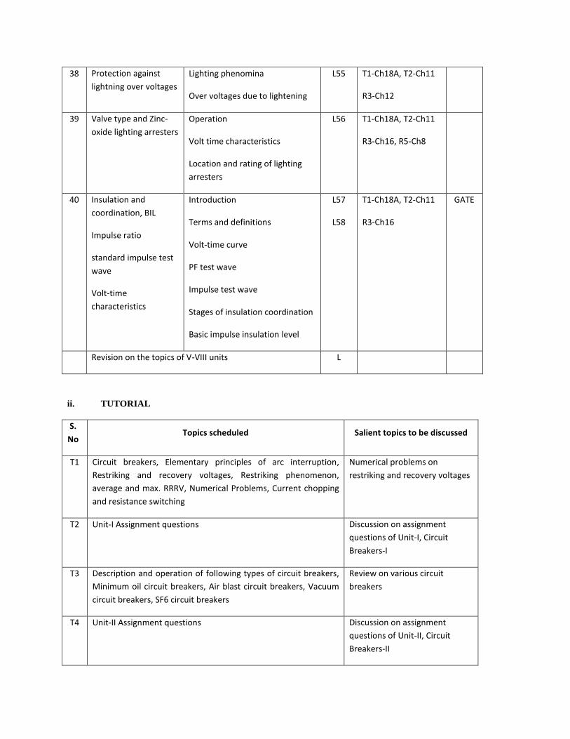
38 Protection against
lightning over voltages
Lighting phenomina
Over voltages due to lightening
L55 T1-Ch18A, T2-Ch11
R3-Ch12
39 Valve type and Zinc-
oxide lighting arresters
Operation
Volt time characteristics
Location and rating of lighting
arresters
L56 T1-Ch18A, T2-Ch11
R3-Ch16, R5-Ch8
40 Insulation and
coordination, BIL
Impulse ratio
standard impulse test
wave
Volt-time
characteristics
Introduction
Terms and definitions
Volt-time curve
PF test wave
Impulse test wave
Stages of insulation coordination
Basic impulse insulation level
L57
L58
T1-Ch18A, T2-Ch11
R3-Ch16
GATE
Revision on the topics of V-VIII units L
ii. TUTORIAL
S.
No Topics scheduled Salient topics to be discussed
T1 Circuit breakers, Elementary principles of arc interruption,
Restriking and recovery voltages, Restriking phenomenon,
average and max. RRRV, Numerical Problems, Current chopping
and resistance switching
Numerical problems on
restriking and recovery voltages
T2 Unit-I Assignment questions Discussion on assignment
questions of Unit-I, Circuit
Breakers-I
T3 Description and operation of following types of circuit breakers,
Minimum oil circuit breakers, Air blast circuit breakers, Vacuum
circuit breakers, SF6 circuit breakers
Review on various circuit
breakers
T4 Unit-II Assignment questions Discussion on assignment
questions of Unit-II, Circuit
Breakers-II

T5 Principle of operation and construction of attracted armature
and balanced beam relays, Induction disc and induction cup
relays, Relays classification: Instantaneous, DMT and IDMT
types, Application of relays: Over current/ under voltage relays,
direction relays, Differential relays
Discussion on various relays
T6 Universal torque equation, Distance relays: Impedance relay,
Reactance relay, Mho and Off-set Mho relays
Review on distance relays
T7 Unit-III Assignment questions Discussion on assignment
questions of Unit-III, Electro
Magnetic and Static Relays
T8 Protection of generators against stator faults, Rotor faults
Abnormal conditions, Restricted earth fault and inter-turn fault
protection, Numerical problems on % winding unprotected.
Numerical problems on %
winding unprotected.
T9 Unit-IV Assignment questions Discussion on assignment
questions of Unit-IV, Generator
Protection
T10 Unit-V Assignment questions Discussion on assignment
questions of Unit-V,
Transformer Protection
T11 Protection of lines: Over current protection, Carrier current
protection, Three-zone distance relay protection using
impedance relays, Translay relay protection of bus bars:
differential protection
Review on feeder and bus-bar
protection
T12 Unit-VI Assignment questions Discussion on assignment
questions of Unit-VI, Feeder and
Bus-Bar Protection
T13 Unit-VII Assignment questions Discussion on assignment
questions of Unit-VII, Neutral
Grounding
T14 Unit-VIII Assignment questions Discussion on assignment
questions of Unit-VIII,
Protection against over voltages

7.5.11 STUDENT SEMINAR TOPICS
1. Protective devices emergence of type B devices, Aravind Ramachandran, Electrical India,
Vol. 48, No.9, Page 106, Sep. 2008
2. Grounding material “Steel as grounding material, study of corrosion process”, K.S.
Sindhu, Electrical India, Vol. 48, No.9, Page 42, Sep. 2008.
3. Relay testing: “Relay interoperability testing”, R. Sriraman and K.S. Swarup, Electrical
India, Vol. 48, No.7, Page 66, July 2008.
4. Switch gear industry stector focus, A. Gokhale, Electrical India, Vol. 48, No.7, Page 86,
July 2008.
5. LV switchgear and specification, K. S. Vakaar, Electrical India, V ol. 48, No.7, Page 92,
July 2008.
6. Switchgear and switch boards, N.P. Jhaveri, Electrical India, Vol. 48, No.7, Page 106, July
2008.
7. Surge over voltages: The slow poision in power supply, Electrical India, Vol. 48, No.5,
Page 114, July 2008.
8. Challenges in time protection philosophies, B. Bhalija and R.P. Maheswari, Electrical
India, Vol. 48, No.4, Page 58, April 2008.
9. Earthing of electrical equipment, S. George, Electrical India, Vol. 48, No.3, Page 96,
March 2008.
10. Soil conditioning for electrical earthing, K.S. Sidhu, Electrical India, Vol. 48, No.2, Page
70, Feb. 2008.
7.5.12 QUESTION BANK
UNIT-I
1 . i. Explain how the arc is initiated and sustained in a circuit breaker when the circuit breaker contacts
separated
ii In a short circuit test on a 132 kV three phase system the breaker gave the
following results: p.f of the fault: 0.4, recovery voltage 0.90 of full line value. The breaking current is
symmetrical and the re-striking transient had a natural frequency of 20 kHz. Determine the average rate of
rise of re-striking voltage.
Assume that the fault is grounded. (May 13)
2. i. Define the terms:
a. restriking voltage
b. recovery voltage
c. RRRV
ii. Derive an expression for the restriking voltage in terms of system voltage, inductance and capacitance
across a C.B. contact when a 3-phase fault takes place. Assume the neutral of the system to be solidly
grounded.
iii. Discuss the principle of arc interruption in an oil circuit breaker. (May 12)
3. i. Explain how the arc is initiated and sustained in a circuit breaker when the circuit breaker contacts
separated.
ii. In a short circuit test on a 132 kV three phase system the breaker gave the following results: p.f of the fault
: 0.4 , recovery voltage 0.95 of full line value. The breaking current is symmetrical and the re-striking
transient had a natural frequency of 16kHz.Determine the rate of rise of re-striking voltage. Assume that
the fault is grounded. (Jan 12)
4. i. Define the terms:
a. restriking voltage
b. recovery voltage
c. RRRV

Derive an expression for the re-striking voltage and RRRV in terms of system resistance, inductance and
capacitance across a C.B. contact when a three phase fault takes place.
ii. In a short circuit test on a 132 kV three phase system the breaker gave the following results: p.f of the fault:
0.4 , recovery voltage 0.90 of full line value. The breaking current is symmetrical and the re-striking
transient had a natural frequency of 20 kHz. Determine the average rate of rise of re-striking voltage.
Assume that the fault is grounded. (Jan 12)
5. i. What is arc quenching? Explain different arc quenching theories.
ii. What is current chopping? Explain. (Jan 12)
6. i. Explain the various testing of circuit breakers.
ii. Discuss about the ratings of circuit breakers. (Jan 12)
7. Calculate the RRRV of a 220kV circuit breaker with earthed neutral. The short circuit test data obtained is
as follows:
The current breaker is symmetrical and the restriking voltage has an oscillatory frequency of 15 kHz. The
power factor of the fault is 0.2. Assume the short circuit to be an earthed fault. (May 10)
8. i. Explain about current zero interruption and what are its advantages?
ii. ge rate of rise of
restriking voltage, when the circuit breaker opens. (May 10)
9. Write a short notes on the rate of restriking voltage and explain its importance in arc extinction.(May 10)
10. A Circuit Breaker is rated as 2500A, 1500MVA, 33kV, 3 secs, 3-phase oil circuit breaker .Determine the
rated symmetrical breaking current, rated making current, short time rating and rated service voltage.
(May 10)
11. For a 132kV system, the reactance and capacitance up to the location of circuit brea
respectively. Calculate the following: (May 10, Sep 08, Apr 05, Jan 03)
i. The frequency of transient oscillation.
ii. The maximum value of restriking voltage across the contacts of the circuit breaker.
iii. The maximum value of RRRV
12. In a 132kV system, the reactance per phase up to the location of the circuit breaker is 5 ohms and
i. the maximum value of the restriking voltage,
ii. the maximum value of RRRV and
iii. the frequency of transient oscillations. (Apr 09)
13. Write a short notes on the rate of restriking voltage and explain its importance in arc extinction.(Apr 09)
14. A generator connected through a 3-cycle Circuit Breaker to a transformer is rated 10MVA, 13.8kV with
reactances of X”d = 10%, X’d=15% and Xd =100%. It is operating at no load and rated voltage when a 3-
phase short circuit occurs between the breaker and the transformer. Determine
i. the sustained short circuit current in breaker;
ii. the initial symmetrical rms current in the breaker;
iii. the maximum possible d.c component of the short circuit current in the breaker;
iv. the momentary current rating of the breaker;
v. the current to be interrupted by the breaker and
vi. the interrupting kVA. (Apr 09, 08)
15. i. Why is current interruption easier in an a.c circuit than in a d.c circuit?
ii. An OCB is rated for 1000MVA, 2 kA, 66 kV, 3 phase, 3 sec. what are its
a. Rated operating voltage
b. Rated operating current

c. Rated symmetrical breaking current. (Apr 09)
16. Explain Slepian’s theory of arc interruption and discuss its limitations. How does energy balance theory,
explain the process of arc interruption? (Sep, Apr 08)
17. Explain the terms recovery voltage, restriking voltage and RRRV. Derive the expression for the restriking
voltage in terms of system capacitance and inductance. (Sep 08, Jan 03)
18. i. Discuss the performance of a circuit breaker when capacitive currents are interrupted? (Sep 08)
ii. Ina system of 132kV, the line to ground capacitance is 0.01F and the inductance is 5H. Determine the
voltage appearing across the pole of a Circuit Breaker. If a magnetizing current of 5ampes (instantaneous
value) is inter-rupted. Determine also the value of resistance to be used across the contacts to eliminate the
restriking voltage.
19. Discuss the recovery rate theory and energy balance theory of arc interruption in a circuit breaker.
(Sep 08, Apr 07, 05, 03) 20. Explain resistance switching in detail with relevant diagrams and derive the expression of damped
oscillation. (Sep 08, Apr 06, 04, 03, Nov 03)
21. Write short notes on the following.
i. Making capacity
ii. Short time current rating
iii. Rated voltage, current and frequency
iv. Rated operating duty (Sep 08, 06, Apr 04, Nov, Apr, Jan 03)
22. i. Explain briefly about various Switch gear components. (Apr 08)
ii. Give the importance of ratings and specifications of Circuit Breaker.
23. Calculate the RRRV of a 220kV circuit breaker with earthed neutral. The short circuit test data obtained is
as follows: The current breaker is symmetrical and the restriking voltage has an oscillatory frequency of 15
kHz. The power factor of the fault is 0.2. Assume the short circuit to be an earthed fault. (Apr 08)
24. A 50 Hz, 11 Kv, three phase alternator with earthed neutral has a reactance of 5 ohm/phase and is
connected to the bus-bar through a circuit breaker. The capacitance to earth between the alternator and the
circuit breaker is 0.02 microfarad per phase. Assume the resistance of the generator to be negligible.
Calculate the following.
i. Maximum value of voltage across the contacts of the circuit breaker.
ii. Frequency of ossillation
iii. The average rate of rise of restriking voltage upto first peak (Apr 08)
25. In a 132 kV system, inductance and capacitance upto the location of the circuit breakers are 0.4H and 0.015
microfarad respectively. Determine (Apr 08)
i. The maximum value of restriking voltage across the contact of the circuit breakers.
ii. Frequency of transient oscillations and the maximum value of RRRV.
26. i. Explain the Phenomenon of current chopping in a circuit breaker. What measures are taken to reduce it.
ii. A circuit interrupts the magnetizing current of a 100MVA transformer at 220kV. The magnetizing current
is 5% of the full load current. Determine the maximum voltage which may appear across the Gap of the
breaker when the magnetizing current is interrupted at 53% of its peak value. The stray capacitance is 2500
microfarad. The inductance is 30H (Apr 07, 04, Nov 03)
27. Explain the following in detail:
i. Symmetrical breaking capacity
ii. Asymmetrical breaking capacity
iii. Rating of circuit breakers. (Sep 06, Nov, Apr 03)

28. i.In a 132kV system, the reactance and capacitance up to the location of the circuit breaker
is 5 ohms and 0.02microfarad respectively, a resistance of 500 ohms is connected across
the break of the circuit breaker. Determine the natural frequency and damped frequency of
oscillation and also find its critical resistance.
ii. Explain the terms recovery voltage and restricting voltages. (Sep 06)
29. Explain the reason for initiation of electric arc during contact separation. Also discuss
which of these is primarily responsible for creation of arc in circuit breakers and why?
(Apr 05, 03)
30. i. Explain the following.
a. Classification of restriking transients
b. Restriking voltage characteristics
ii. Explain with a neat diagram the factors affecting t he restriking voltage characteristics.
(Apr 05, 03)
31. In a 132kV system, the inductance and capacitance per phase up to the location of the
circuit breaker is 10H and 0.02 microfarad, respectively. If the circuit breaker interrupts a
magnetizing current of 20A (instantaneous), current chopping occurs. Determine the
voltage which will appear across the circuit breaker. Also determine the resistance that
should be connected across the contacts of the circuit breaker to eliminate restriking
voltage. (Apr 04)
32. A 3-phase oil circuit breaker is rated at 1000A, 1500 MVA, 33 KV, 4S. Find the rated
normal current, symmetrical breaking current, making current and short time current
rating. (Jan 03)
33. A 3-phase oil circuit breakaer is rated 25000 A, 1200 MVA, 33 kV, 3 seconds. Determine
the rated symmetrical breaking current, rated making current, short time rating and rated
service voltage.
(Jan 02) 34. In a short circuit test on a 3-pole, 132 kV, circuit breaker the following observations are
made :
Power factor of fault 0.4. The recovery voltage 0.9 times full line value, the breaking current symmetrical,
the frequency of oscillations of restriking voltage 16 kHz. Assume that the neutral is grounded and the fault
does not involve ground. Determine the average rate of restriking voltage. (Jan 02)
35. A 66 kV 50 Hz, 3 -phase alternator has an earthed neutral. The inductance and Capacitance
of the system per phase are 7 mH and 0.01 mf respectively. The short -circuit test gave the
following results: power factor of fault 0.25, fault current symmetrical recovery voltage is
90% of full line voltage. Assuming that the fault is isolated from the ground, calculate the
RRRV. (Jan 01)
36. Explain how an arc is initiated and sustained in a circuit breaker when the circuit breaker contacts separate.
(Jan 00)
37. The interrupting time of a circuit breaker is the period between the instant of
i. Initiation of short circuit and the arc extinction on an opening operation
ii. Energizing of the trip cir cuit and the arc extinction on an opening operation
iii. Initiation of short circuit and the parting of primary arc contacts
iv. Energizing of the trip circuit and the parting of primary arc contacts (GATE 03)
38. Three sections of a feeder are provided with circuit breakers CB1, CB2, CB3, CB4, CB5
and CB6. For a fault F as indicated in Fig.
i. CB5 must be set to trip after CB1 trips
ii. CB5 must be set to trip after CB3 and CB4 trips
iii. CB5 must be set to trip after CB2 trip

iv. CB5 must be set to trip before CB1, CB2, CB3 and CB4 trips (GATE 99)
39. A shunt reactor of 100 MVAr is operated at 98% of its rated voltage and at 96% of its
rated frequency. The reactive power absorbed by the reactor is:
a. 98 MVAr b. 104.02 MVAr
c. 96.04 MVAr d. 100.04 MVAr (GATE 98)
40. Reactance relay is normally preferred for protection against
a. earth faults b. phase faults
c. open-circuit faults d. None of the above (GATE 97)
41. The synchronous reactance of a 200 MVA, 10 kV, 3-phase, 50 Hz generator is 1.0 p.u. at
its own base. Its p.u. reactance at 100 MVA, 20 kV base will be.... ..... (GATE 97)
42. A 3-phase transformer bank consists of three identical 2300/230V, 15 kVA single -phase
transformers connect in delta/delta. The bank supplies a 20 kVA, unity p.f. 3 -phase load.
If one of the single -phase transformer develops a fault, and is removed, the load carried by
each of the two transformers now operating in open delta will be . ............ .. kV A.(GATE
97)
43. In the power system circuit diagram shown in Fig., the current limiting reactor X is to be
chosen such that the feeder breaker rating does not exceed 425 MVA. The system data is
as follows:
Feeder transformer reactance: 10% on 50 Mva b ase.
The generating source A, B, C have individual fault levels at 1000 MVA with respective
generator breakers open. Ignore pre -fault currents and assume 1.0 p.u. voltages throughout
before fault. Assume common base of 1000 MVA. (GATE 96)
UNIT-II
1. Explain the construction and operation of SF6 circuit breaker with a neat sketch.
What are the advantages of SF6 circuit breaker over other circuit breakers? (Jan 13)
2. With a neat sketch explain the operation of
i. Minimum oil circuit breaker and
ii. Vaccum SF6 circuit breaker. (May 12)
3. Explain the construction and operation of minimum oil circuit breaker with a neat sketch. Discuss its
performance characteristics. (Jan 12)
4. Explain the construction and operation of SF6 circuit breaker with a neat sketch. (Jan 12)
5. Explain the construction and operation of Vacuum circuit breaker with a neat sketch. (Jan 12)
6. Explain the construction and operation of air blast circuit breaker with a neat sketch. (Jan 12)
7. i. Compare the arc rupture in oil and air blast circuit breakers and summarize the relative
advantages and disadvantages of these types of switch gear.
ii. Explain the operating duty of a circuit breaker. (May 10, Sep, Apr 08)
8. Distinguish between oil circuit breakers and SF6 circuit breakers? (May 10)
9. Explain the process of current chopping in SF6 circuit breakers. (May 10, Jan 03)
10. How eoes the current effect the arcing time in (May 10)

i. Oil circuit breaker
ii. Air blast circuit breaker
11. i. With the help of neat sketches, describe the principle of resistance switching units in an
Air blast circuit breaker.
ii. Describe the construction of a vacuum interrupter and vacuum circuit breaker. (Apr 09)
12. Describe the principle of air blast circuit breaker with the help of neat sketches, explain
the construction of a typical EHV air blast circuit breaker. (Apr 09)
13. Distinguish between Air Blast circuit breaker and oil circuit breakers? (Apr 09)
14. i. What are the key features of SF6 Circuit Breaker over other circuit breakers.
ii. Write a short notes on the maintenance of Oil circuit breaker. (Apr 09)
15. What are the necessary auxiliaries of ABCB? Describe compressed air system for supplying compressed air
to the air blast circuit breakers? (Sep 08)
16. Explain current chopping in VCB. Explain the function of RC surge suppressors used with
vacuum switchgear for motor switching. (Sep 08)
17. Explain the principle of arc extinction and What are the dif ferent methods of arc
extinction. (Apr 08)
18. Classify the types of circuit breakers when the arc quenching medium is the criterion?
(Sep 08, Apr 08, 07, 05, 03) 19. Mention the voltage range for which a particular type of circuit breaker is recommended.
(Sep 08, Apr 08, 07, 05, 03) 20 i. Why is current chopping not a serious problem with vacuum circuit breakers. (Apr 07, 03)
ii. How does SF6 breakers differ from an air blast circuit breakers?
iii. What are the possible applications of vacuum circuit breakers?
21. In what aspects is a minimum oil circuit breaker an improvement over the bulk oil
breakers.
(Nov, Jan 03)
22. Explain how SF6 gas in ideally suitable for circuit breaker. (Nov 03)
23. Expplain the factors which are influe ncing the performance of an air blast circuit breaker.
(Nov 03)
24. Explain with a neat sketch the working of a Air blast circuit breaker. (Nov 03)
25. Discuss the performance of a circuit breaker when capacitive currents are interrupted.
(Nov, Jan 03)
26. Explain the operation of SF6 circuit breaker with relevant sketch in a detailed manner.
(Nov, Jan 03)
27. What are the various types of SF6 circuit breakers. Explain them in detail with a neat sketch. (Jan 03)
28. What are the merits and demerits of SF6 breakers. (Jan 02)
29. Describe the construction, principle of operation and application of SF6 circuit breaker.
(Jan 01)

30. Draw the constructional details of a minimum oil circuit breaker and explain it in detail
along with its operation. (Jan 00)
31. Explain the process of arc quenching in SF6 breaker and its applications. (Jan 00)
32. Describe the principle of operation of an airblast circuit breaker with a near sketch.
(Jan00)
33. Explain briefly the following types of air-blast circuit breaker.
i. Axial-blast type
ii. Cross-blast type
34. What are the applications of SF6 gas?
35. Explain precautions to be taken to avoid dust, moistore, and leakage in case of SF6 circuit breaker?
36 Describe the behavior of electric arc in high vaccum?
37. Explain the process of arc extinction in high vaccum?
UNIT-III
1. i. Explain the different structures used for mho relay.
ii. Explain the characteristics of mho relay.
iii. Differentiate between static and electromagnetic relays. (May 13)
2. i. Write the comparison between static relays and electromagnetic relays.
ii. What is Universal torque equation? Using this equation derive the characteristics of reactance relay.
iii. Write the applications of
a. impedance relay b. mho relay c. over current relay
d. under voltage relay and e. percentage differential relay. (May 12)
3. i. What is universal torque equation? Using this equation derive the following characteristics:
a. Impedance relay b. Reactance relay c. Mho relay.
ii. Explain the characteristics of IDMT realy. (Jan 12)
4. Explain the principle and operation of Directional over current relay. Discuss its various characteristics.
(Jan 12)
5. i. Define the following:
a. Relay b. Pick-up level c. Reset level d. Operating time. e. Over-reach
ii. What are the functional characteristic of protective relays?
iii. Differentiate between static and electromagnetic relays. (Jan 12)
6. i. Explain the different structures used for mho relay.
ii. Explain the characteristics of mho relay.
iii. Explain the basic connection for phase fault relays. (Jan 12)
7. Discuss with a neat sketch the general principle of operation of a distance protection scheme. (May 10)
8. What is the effect of ‘arc-resistance’ on the performance of impedance relay? and explain how it is
Overcome in case of reactance relay? (May 10)
9. Discuss the Directional Impedance relay and Explain the Directional Impedance relay by means of its
characteristic on R-X plane. (May 10)

10. A 6.6 kV, 4000 kVA star connected alternator with a transient reactance of 2 ohm/phase and negligible
resistance, is protected by a circulating current protective system. The alternator neutral is earthed through
a resistor of 7.5 ohm. The relays are set to operate when there is an out of balance current of 1A in the
secondary windings of the 500/5 A current transformer. What percentage of each phase winding is
protected against an earth fault?
(May 10) 11. A 20MVA transformer which may be called upon to operate at 30% over load, feeds 11kV busbar through
a circuit breaker. Other circuit breakers supplies out going feeders. The transformer circuit breaker is
equipped with 1000/5A CTs and the feeder circuit breakers with 400/5A CTs and all sets of CTs feed
induction type over current relays. The relay's on the feeder circuit breakers have 125% plug setting and a
0.3 time setting. If a 3-phase fault current of 5000A flow from transformer to one of the feeders, find
operating time of the feeder relay, the minimum plug setting of transformer relay and its time setting.
Assuming a discriminative time margin of 0.5sec. (May 10)
12. State the various applications of over-current relaying. Distinguish between ’inverse characteristic’ and
‘definite characteristic’. (Apr 09)
13. Why are the differential relays more sensitive than over current relays, Explain? (Apr 09)
14. Explain the ‘Differential protection’. State the various applications of differential protection. (Apr 09, 08)
15. i. Expain the following terms with respect to switch gear protection
a. Pick up level
b. operating time
c. Reach
d. Under Reach
e. Over Reach.
ii. An earth fault setting relay has a setting of 20%, current rating 5A, it is connected to a C.T of ratio 500:5.
Calculate pick up current in primary for which the earth fault relay operates. (Apr 09)
16. Define the following terms and explain their significance in distance protection (Sep, Apr 08)
i. Reach of a distance relay.
ii. Under reach.
17. Explain the terms (Sep 08)
i. Current setting
ii. Plug setting multiplier
iii. Time- setting multiplier
iv. Primary protection and back up protection.
18. Distinguish between Over current relays, Directional relays and Differential relays? (Sep 08)
19. i. Explain in detail the role of pro tective relays in a power systems. (Sep 08)
ii. Discuss in detail the causes and types and frequency of faults encountered in a power
system.
20. Explain the merits and demerits of static relays. (Sep 08, Nov 07, Apr 06)
21. i. What is meant by directional feature of a directional over current relay? Describe the
construction, principle of operation and application of a directional over current relay.
ii. What is the difference between a polarized mho and simple mho relay. What are self-
polarized and cross-polarized mho relays? (Sep 08, 06, Nov 07, Apr 04, Jan 03)
22. i. Discuss the choice between impedance, reactance and Mho type relays. (Sep 08, Nov 07)
ii. Transformer: 5MVA, Y/ , X=6% The transmission line sections AB and BC are to be protected by Mho
distance relays. The system is as shown in the figure. If the C.T. ratio is 300/5 and C.T. ratio is

166000/110V and a 3-phase short circuit fault of zero impedance occurs at F, find the impedance seen by
the relays and determine the setting of the relays for high speed protection of line AB and backup
protection for line BC, when the relays are located atend A.
23. With the help of neat sketch explain the principle of operation of Differential relays. (Sep 08)
24. Write short notes on
i. Reactance relay
ii. Mho relay
iii. Directional Impedance relay. (Sep 08, Apr 05, Apr 04)
25. Describe the various types of construction of attracted armature type relay. Why can they operate in a.c and
d.c?. State its salient features. (Apr 08)
26. i. Describe the construction of an induction disc relay. State its principle of operation. What are the
advantages to induction relays. How is the current setting and time setting obtained? (Apr 08)
ii. With a neat sketch, describe the difference between definite characteristic and inverse characteristic of
relays.
27. i. Where are the relays having extremely inverse and very inverse characteristics used? What types of
characteristics are used for protecting rectifiers, and for replacement off uses?
ii. Explain how the mho characteristic realized using a sampling comparator? (Nov 07, 03, Apr 07, 05)
28. i. What type of protection will you recommend for a power line operating at (Nov 07)
a. 11 K.V. b. 33 K.V. c. 66K.V.
ii. Discuss in detail with relevant diagrams the shaded pole type I.D.M.T. relay used in practice.
29. Determine the time of operation of the relays placed at location No. 1 and 2 assuming that fault current is
2000amps,C.T.ratio 200/1, relay 1 set at 100% and 2 at 125%and that the relay No.1 has a time multiplier
of 0.2. The time grading margin between the relays is 0.5. sec for discrimination. Assume the relay to have
2.2 seconds I.D.M.T. Characteristic. As shown in figure. (Apr 07, 06)
30. i. Describe briefly some important types of electromagnetic attraction relays.
ii. Describe the various steps for calculating the actual relay operating time. (Sep 06, Apr 03)
31. i. Explain how to provide directional feature of Impedance and Reactance relay.
Explain why the directional feature provided for Impedance relay.
ii. Explain why attracted armature type relays are noisy? What measures are take to minimize
the noise.
(Apr 06, Nov 03) 32. i. Describe the principle of impedance type distance relay and explain its characteristics on
V-I And R-X planes.
ii. Derive expression for torque developed by a double activating quantity distance
relay.Show that the relay operates when fault is within the protected distance of line.
(Apr 05)
33. i. Explain the process of fault clearing with the help of a neat sketch.
ii. Classify the various types of over current relays and give their application along with
approximate characteristics. (Apr 05)
34. i. Discuss the effect of power surges on the performance of different types of distance
relays.
ii. Discuss in detail the applications of over current relays. (Apr 05)
35. i. Discuss the principle of operation of an Induction disc relay with r elevant diagrams.
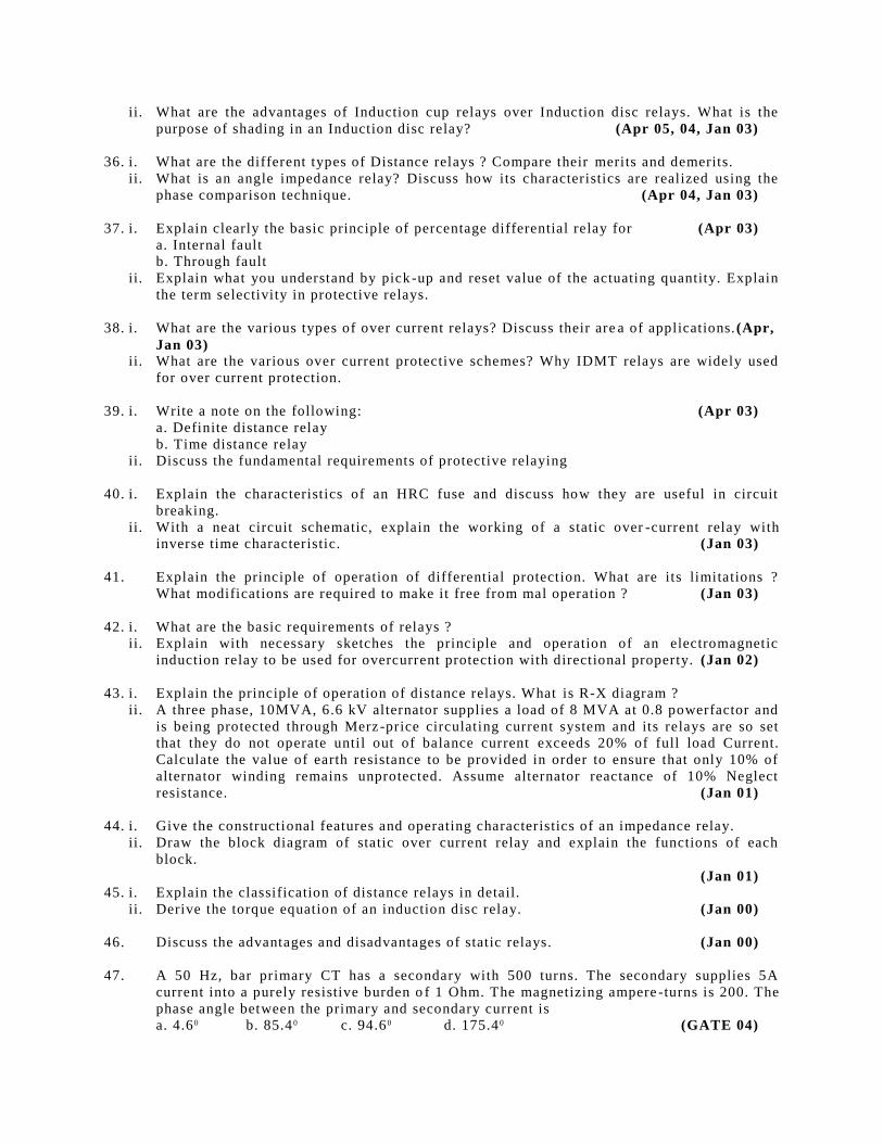
ii. What are the advantages of Induction cup relays over Induction disc relays. What is the
purpose of shading in an Induction disc relay? (Apr 05, 04, Jan 03)
36. i. What are the different types of Distance relays ? Compare their merits and demerits.
ii. What is an angle impedance relay? Discuss how its characteristics are realized using the
phase comparison technique. (Apr 04, Jan 03)
37. i. Explain clearly the basic principle of percentage differential relay for (Apr 03)
a. Internal fault
b. Through fault
ii. Explain what you understand by pick -up and reset value of the actuating quantity. Explain
the term selectivity in protective relays.
38. i. What are the various types of over current relays? Discuss their are a of applications. (Apr,
Jan 03) ii. What are the various over current protective schemes? Why IDMT relays are widely used
for over current protection.
39. i. Write a note on the following: (Apr 03)
a. Definite distance relay
b. Time distance relay
ii. Discuss the fundamental requirements of protective relaying
40. i. Explain the characteristics of an HRC fuse and discuss how they are useful in circuit
breaking.
ii. With a neat circuit schematic, explain the working of a static over -current relay with
inverse time characteristic. (Jan 03)
41. Explain the principle of operation of differential protection. What are its limitations ?
What modifications are required to make it free from mal operation ? (Jan 03)
42. i. What are the basic requirements of relays ?
ii. Explain with necessary sketches the principle and operation of an electromagnetic
induction relay to be used for overcurrent protection with directional property. (Jan 02)
43. i. Explain the principle of operation of distance relays. What is R-X diagram ?
ii. A three phase, 10MVA, 6.6 kV alternator supplies a load of 8 MVA at 0.8 powerfactor and
is being protected through Merz -price circulating current system and its relays are so set
that they do not operate until out of balance current exceeds 20% of full load Current.
Calculate the value of earth resistance to be provided in order to ensure that only 10% of
alternator winding remains unprotected. Assume alternator reactance of 10% Neglect
resistance. (Jan 01)
44. i. Give the constructional features and operating characteristics of an impedance relay.
ii. Draw the block diagram of static over current relay and explain the functions of each
block.
(Jan 01) 45. i. Explain the classification of distance relays in detail.
ii. Derive the torque equation of an induction disc relay. (Jan 00)
46. Discuss the advantages and disadvantages of static relays. (Jan 00)
47. A 50 Hz, bar primary CT has a secondary with 500 turns. The secondary supplies 5A
current into a purely resistive burden o f 1 Ohm. The magnetizing ampere -turns is 200. The
phase angle between the primary and secondary current is
a. 4.6 0 b. 85.4 0 c. 94.6 0 d. 175.4 0 (GATE 04)

48. The core flux in the CT of Prob Q 28, under the given operating cond ition is
a. 0 b. 45.0 mWb c. 22.5 mWb d. 100.0 mWb (GATE 04)
49. A list of relays and the power system components protected by the relays are given in
Group I and Group II respectively. Choose the correct match from the four choi ces given
below : (GATE 03)
Group - I Group - II
P Distrance relay 1 Transformers
Q Under frequency relay 2 Turbines
R Differential relay 3 Bushers
S Buchholz relay 4 Shunt capacitors
5 Alternators
6 Transmission lines
a) P-6, Q-5, R-3, S-1 b) P-4, Q-3, R-2, S-1
c) P-5, Q-2, R-1, S-6 d) P-6, Q-4, R-5, S-3
50. The transmission line distance protection relay having the property of being inherently
directional is
i. impedance relay
ii. MHO relay
iii. OHM relay
iv. reactance relay (GATE 03)
51. In an inverse definite minimum time, electromagnetic type over -current relay the
minimum time feature is achieved because of
i. saturation of the magnetic circuit
ii. proper mechanical design
iii. appropriate time delay element
iv. electromagnetic damping (GATE 00)
52. The plug setting of a negative sequence relay is 0 -2A. The current transformer ratio is 5.1.
The minimum value of line to line fault current for the operation of the rel ay is :
(GATE 00)
53. A 50 MVA, 132/66 KV, D/Y, 3-f power transformer is protected by percentage differential relays. If the
current transformer (CTS) located on the delta and star sides of the power transformer are 300/5A and
1200/5A respectively, determine
i. The output current at full load
ii. The relay current at full load
iii. The minimum relay current setting to permit 25% overload (GATE 91)
54. Reactance relay is normally preferred for protection against
i. earth faults
ii. phase faults
iii. open-circuit faults
iv. None of the above (GATE 97)
UNIT-IV
1. i. A 6.6 kV, 5 MVA star connected generator has a reactance of 1.5 ohm per phase and negligible
resistance. Merz-Price protection scheme is used which operates when the out of balance of the current
exceeds 25% of the full load current. The neutral of the generator is grounded through a resistance of 8
ohms. Determine the proportion of the winding which remains unprotected against earth fault. Show
that the effects of alternator reactance can be ignored.
ii. Discuss the generator protection schemes for

i) Loss of excitation ii) Overload iii) loss of prime mover. (May 13)
2. i. What is restricted earth fault protection for alternators? Why is this form of protection used for alternators
even though it does not provide protection for the complete winding?
ii. With a neat sketch explain the protection of alternator against stator faults and rotor faults. (May 12)
3. Why generators are to be protected? Explain the protection schemes for the following Faults
i. Unbalanced loading
ii. Failure of prime mover
iii. Restricted earth fault
iv. Over speed protection. (Jan 12)
4. i. Discuss the various types of faults associated with generator.
ii. Discuss the generator protection schemes for
a. Loss of excitation b. overload c. Inter-turn fault. (Jan 12)
5. Explain the following protection mechanism for generators.
i. Stator protection
ii. Inter-turn fault protection
iii. Rotor protection
iv. Failure of prime mover. (Jan 12)
6. i. A 6.6 kV, % MVA star connected generator has a reactance of 1.5 ohm per phase and negligible resistance.
Merz-piece protection scheme is used which operates when the out of balance of the current exceeds 25%
of the full load current. The neutral of the generator is grounded through a resistance of 8 ohms. Determine
the proportion of the winding which remains un-protected against earth fault. Show that the effects of
alternator reactance can be ignored.
ii. Explain the alternator protection schemes for (i) Inter turn faults ii) Over voltage protection. (Jan 12)
7. An 11 kV, 100MVA generator is grounded through a resistance of 6 ohms The C.T.s have a ratio
1000/5.The relay is set to operate when there is an out of balance current of 1 A. What percentage of the
generator winding will be protected by the percentage differential scheme of protection.(May 10, 07, 04)
8. i. Explain how the inclusion of a resistance in the neutral earthing circuit of an alternator affects the
performance of the differential protection of the three-phase stator.
ii. Describe how protection is provided in large turbo alternators against earth fault in the rotor.
(May 10, 09, 08, 07, Sep 08) 9. i. Enumerate the relaying schemes which are employed for the protection of modern alternator.
ii. Describe with a neat, the percentage differential protection of a modern alternator. (May 10)
10. A 6.6 kV, 4000 kVA star connected alternator with a transient reactance of 2 ohm/phase and negligible
resistance, is protected by a circulating current protective system. The alternator neutral is earthed through
a resistor of 7.5 ohm. The relays are set to operate when there is an out of balance current of 1A in the
secondary windings of the 500/5 A current transformer. What percentage of each phase winding is
protected against an earth fault? (May 10)
11. The neutral point of a 3- hed through a resistance of 5W, the relay is set
to operate when there is an out of balance current of 1.5 A. The C.T.s have a ratio of 1000/5. What
percentage of winding is protected against an earth fault and what should be the minimum value of earthing
resistance to protect 90% of the winding? (May 10, Jan 03)
12. Discuss the unbalanced loading and overload protection in alternators. ‘Overload
protection is not necessary for alternators’ ? Justify yourself? (Apr 09, Sep 08)
13. What are Restricted earth faults and Inter -turn faults in generators? Explain the protection
schemes employed for these faults. (Apr 09)

14. Discuss the different types of faults that can occur on a generator and the protection
schemes employed. (Apr 09)
15. Explain with a diagram, the application of the Merz -Price circulating current system to the
protection of alternators. What precautions must be taken in installing this system? (Sep,
Apr 08)
16. Explain a scheme of protection for failure of alternator excitation. (Sep 08, Apr 08, 07)
17. Explain with neat diagram the Merz price protection for generator. (Sep 08, Apr 07)
18. i. Enumerate the relaying schemes which are employed for the protection of a modern
alternator.
ii. A 11KV, 100MVA generator is provided wi th dierential scheme of protection. The
percentage of the generator winding to be protected against phase to ground fault is 80% .
The relay is set to operate when there is 15% out of balance current. Determine the value
of the resistance to be placed in t he neutral to ground connection. (Sep 08, Apr 06)
19. Show in detail, the protection arrangement of a 60 MW generator provided with :
i. Differential protection
ii. Back-up over - current protection through faults
iii. Standby earth fault protection in neutral connection. (Apr 08, 06, 05, 04)
20. i. 3300V, 3-phase turbo alternator has a maximum continuous rating of 2000 kW at 0.8 p.f.
and reactance is 12.5%. It is equipped with Merz -Price circulating current protection
which is set to operate at fau lt currents not less than 200A. Find what value of the neutral
earthing resistance leaves 10% of windings unprotected.
ii. Describe percentage differential protection for transformers. State the advantages.
(Apr 08)
21. Discuss any one of the stator protection schemes for generators above 1MW. (Apr 08)
22. A 11KV,100MVA alternator is provided with differential protection. The percentage of winding to be
protected against phase to ground fault is 85%. The relay is set to operate when there is 20% of out of
balance current. Determine the value of the resistance to be placed in the neutral to ground connection.
(Apr 07)
23. i. What is a direct connected generator? (Apr 06)
ii. Mention protective schemes for a direct connected generator. Explain any one of these
schemes.
24. What is restricted earth fault protection for alternators? Explain the difference between
primary protection and back up protection. (Apr 06, Jan 03)
25. Explain briefly with schematic diagram,the protective gear for alternators connected to
grid against
i. Fault between phases and
ii. Fault between turns in one of the phase windings. (Sep 06, Apr 03)
26. i. Discuss the protection employed against the loss of excitation of an alternator.
ii. Is there any back up protection employed for the protection of an alternator. If yes,
discuss the scheme, which is used for this purpose. (Sep 06, Apr 05, Nov 03)
27. What is the effect of balanced load on the generator ? Which part is damaged due to
sustained unbalanced currents ? (Apr 04)

28. i. What are the abnormal conditions in a large synchronous generator against which
protection is necessary?
ii. Draw neatly the differential protection scheme of an alternator. Discuss its limitations
and suggest remedies to overcome them. (Nov 03, Jan 03)
29. i. State the protections commonly provided for a 100 MW generator.
ii. A 3-phase, 11 kV, 15,000 kVA star connected alternator has differentail protection. The
neutral is earthed through a resistance of 8 oh ms. The relay operates for out of balance of
18% full load. Calculate percentage of winding unprotected against ground fault? (Apr 03)
30. i. Why resticed earth fault protection is provided to alternators though it does not provide pretection against
earth fault to the complete winding? What is the justification of providing this protection? (Apr 03)
ii. Calculate the required value of neutral resistance for a 3-phase, 11 KV alternator so as to protect 70% of
the winding against earth fault by a relay with pick up current of 1A. The neutral CT has a ratio of 250/5.
31. Describe the prime mover failure protection schemes of an alternator. (Jan 03)
32. Write short notes on Prime mover failure protection scheme of generators. (Jan 03)
33. Explain the protection scheme employed for the protection of an alternator by Rotor
Protection against loss of excitation. (Jan 02)
34. Describe with a neat diagram differential method of protection of generators. (Jan 00)
35. A 20 MVA, 6.6 kV, 3 -phase alternator is connected to a 3-phase transmission line. The per
unit positive sequence, negative sequence and zero sequence impedances of the alternator
are j0.1, j0.1 and jo.04 respectively. The neutral of the alternator is connected to ground
through an inductive reactor of j0.05 P.U. The per unit positive, negative and zero
sequence impedances of the transmission line are j0.1, j0.1 and j0.3 respectively. All per
unit values are based on the machine ratings. A solid ground fault occurs at one phase of
the far end of the transmission line. The voltage of the alternator neutral with respect to
ground during the fault is : (GATE 03)
36. The neutral of 10 MVA, 11 kV alternator is earthed through a resistance of 5 ohms. The
earth fault relay is set to operate at 0.75A. The CT's have a ratio of 1000 : 5. What
percentage of the alternator winding is protected?
(a) 85% (b) 88.2% (c) 15% (d) 11.8% (GATE 98)
UNIT-V
1. Describe the construction, principle of operation with a neat sketch and applications of Buchholz’s Relay.
Why this form of protection is ideal for transformer? (Jan 13)
2. i. Explain the principle of Merz-piece protection scheme used for power transformers. What are the
limitations of this scheme? How they are overcome?
ii. A 3-phase, 66/ 11 kV star delta connected transformer is protected by Merz-piece protection scheme. The
CTs on the LT side have a ratio of 420/5 amps. Find the ratio of CTs on the HT side.
(Jan 13)
3. i. Describe with a neat diagram, a circulating current protection scheme 3-phase . 1MVA, 11 kV/400 V delta-
star transformer. If the current transformers have a nominal secondary current of 5 amps, calculate their
ratios.
ii. Explain the biased differential protection scheme used for transformers. (Jan 12)
4. i. A 3-phase , 33/ 11 kV star delta connected transformer is protected by Merz-piece protection scheme. The
CTs on the LT side have a ratio of 1000/5 amps. Find the ratio of CTs on the HT side.
ii. Explain the construction and operation of Bucchholz’s relay. (Jan 12)

5. i. A 3-phase 66/11 kV star-delta connected transformer is protected by Merz-price protection system. The
C.Ts on the L.T side have a ratio of 420/5 amps. Show that the C.Ts on the H.T side will have a ratio of
70:5/”3.
ii. With a neat sketch explain the principle of operation of Buchholtz relay.
iii. Discuss the percentage differential protection of transformer. (May 11)
6. Explain with a neat circuit diagram , about the percentage differential protection scheme to protect Y -
transformer. (May 10)
7. i. Discuss about differential protection scheme for transformers.
ii. A 3-phase transformer rated for 33kV/6.6kV is connected star/delta and the protecting current transformer
on the low voltage side have a ratio of 400/5. Determine the ratio of the current transformer on the HV side.
(May 10) 8. For protecting a 132/33kV, 50 MVA power transformer from internal faults, what are the different
protection schemes normally used? Discuss one of the them in brief, with sketch. (May 10)
9. i. Discuss earth fault protection for transformers. (Apr 09, Sep 08)
ii. A 3-phase transformer rated for 33kV/6.6kV is connected star-delta and the protecting current transformer
on the low voltage side have a ratio of 400/5. Determine the ratio of the current transformer on the HV side.
10. Draw the connection diagram of a differential relay for the protection a star-delta transformer. How does
bias the winding of a differential relay restricts malfunctioning of the relay against
i. CT mismatch
ii. Onload changing and
iii. Magnetising current? What is magnetising Inrush current? What is the principle used to make a differential
relay insensitive to magnetizing inrush current. (Apr 09)
11. Describe with a neat sketch, the operation of Buchholtz relay. (Sep 08)
12. What is Buchholtz relay? Which equipment is protected by it? For what types of faults is it employed?
Discuss its working principle. (Sep 08)
13. Discuss the percentage dierential protection scheme of a transformer. (Sep 08, Apr 06)
14. i. A 3-phase, 66/11kV star-delta connected transformer is protected by Merz- price protection system. The
CTs on the LT side have a ratio of 420/5 ampr. Show that the CTs on the HT side will have a ratio of 70: .
ii. Explain with reasons the connections of C.T.s for protecting a delta/star transformer. Write the scheme of
protection for
a. Internal fault and
b. External fault. (Apr 08, 07, Sep 06, Jan 03)
15. i. Discuss biased differential protection for transformers. (Apr 08)
ii. A 3-phase, 33/6.6 kV transformer is connected in star/delta and the protecting current transformer on the
LV side have a ratio of 300/5. What will be the ratio of the current transformer on the HV side?
16. Write short notes on the following: (Apr 08)
i. Different transformer faults
ii. Biased differential protection for transformer
iii. Buchholtz Relay
17. Explain with a neat circuit diagram of the percentage differential protection scheme to protect Y -
transformer..
(Apr 08, Jan 03) 18. What is Buckhholz relay? Discuss its working principle. (Nov 07)
19. Describe the principle of dierential Protection applied to a power transformer.What are the
diculties experienced and how are they overcome? (Sep 06)

20. Three phase 33/6.6 kV transformer is connected star - delta and current transformers on the
low voltage side have ratio 300: 5. What will be the ratio of CT on the high voltage side of
Merz Prize protection is to be adopted. (Sep 06, Apr 03)
21. i. What are the difficulties in the design of C.T for restricted earth fault protection? How
are these difficulties overcome in high impedance protection?
ii. What are switched distance-relaying schemes? Explain them in detail? (Apr 06)
22. i. Define ‘differential protection’ Describe the principle of circulating current differential
protecting
ii. State the various applications of differential protection. (Apr 05)
23. i. What protective devices other than the differential protection are used for the protection
of a large transformer? Briefly describe them.
ii. Show that the torque on the disc of an induction disc relay is maximum when the phase
difference between the two fluxes is 90 0 . (Apr 05)
24. With the help of neat sketches explain the protections of a star - delta power
transformer,against the following abnormal conditions
i. Phase to phase fault
ii. Earth fault
iii. High voltage surges (Apr 05, 04)
25. What is differential protection ? What is percentage differential protection ? Why it is
superior to simple differential protection. Explain the characteristics. (Apr 04)
26. A star-delta, 11kV/6.6 kV transformer is protected by means of differential protection
system. The 6.6 kV delta connected side has CT of ratio 600/5. Calculate CT ratio of HT
side. (Apr 03)
27. Explain the principle of Merz -Price system of protection used for power transformers.
(Jan 02)
28. With the help of neat diagram, explain the protection of Star/Delta transformer using
percentage differential relay. How do you prevent the operation of the relay during
magnetic in-rush currents ?
(Jan 00)
29. In the protection of transformers, harmonic restraint is used to guard against
i. Magnetizing inrush current
ii. Unbalanced operation
iii. Lightning
iv. Switching over-voltages (GATE 01)
30. What factors cause difficulty in applying circulating current to a power transformer? (T1-Ch32)
31. How many faults develop in a power transformer? (T1-Ch32)
32. A star-delta, 11KV/6.6KV transformer is protected by means of differential protection system. The 6.6KV
delta is connected side has C.T of ratio 600/5 calculate CT ratio of HT side? (T1-Ch32)
UNIT-VI
1. i. Explain three zone protection scheme using impedance relays.
ii. Explain carrier current protection scheme with neat diagrams. (Jan 13)
2. i. What is meant by 3- zone protection ? With a neat diagram Explain such scheme of protection for long
lines.
ii. Explain Translay protectin scheme of busbars. (May 12)
3. Explain the three zone protection scheme for a transmission line using
i) Impedance relay ii) Reactance relay (Jan 12)
4. i. Explain the carrier current protection scheme for transmission lines.
ii. Discuss about the settings of the distance relay. (Jan 12)
5. Explain the time graded protection system for feeders. (Jan 12)
6. Explain the differential protection systems for various types of feeders. (Jan 12)
7. i. What are the requirements of protection of lines? (Apr 09, Sep 08, 06)
ii. Write short notes on the following:
a. Fault bus protection
b. Translay scheme.
8. i. Explain over current protection of feeder. (Apr 09, 08)
ii. Explain a scheme of protection for a ring mains.
9. i. Explain bus bar protection need special attention. Why? (Apr 09, 08)
ii. What is back up protection of bus bars?
10. i. What is the main drawback of differential over current protection for bus bars and how is
it overcome.
ii. Explain about voltage differential protect ion of bus bars. (Apr 09)
11. With a neat sketch discuss the differential scheme for bus zone protection. (Sep 08)
12. i. Write a neat sketch, discuss the differential scheme for bus zone protection.
ii. Discuss the working principle of frame leakage protection. (Sep 08, Apr 04)
13. i. Explain over-current protection of feeders. (Sep, Apr 08)
ii. How is the protection system graded with respect to the time of operation of relays.
14. Explain the principle of distance relaying applied to protection of radial transmission
lines. Distinguish between reactance, impedance and mho relays as regards their
applications to distance protection.
(Sep 06)
15. i. Explain how the selection of current and time settings is done in a time current graded
system.
ii. Give schemes of protection for a parallel feeder fed from
a. one end
b. both the ends. (Sep 06, Apr 05, 03)
16. Write short note on the following:
i. Bus Fault protection
ii. Merz-price voltage balance system for protection of feeders. (Sep 06)
17. Give various schemes of protection for feeders. (Sep 06)
18. i. Discuss the considerations which determine the need for a busbar protection.
ii. Discuss any one busbar protection scheme in detail. (Apr 06)

19. Distinguish between unit protection and non unit protection. What are the various methods
of protecting a transmission line by unit protection? (Apr 06)
20. What is meant by 3 Zone protection? Give such schemes of protection for
a. Short length lines b. Medium length lines c. Long lines. (Apr 06, Jan 03)
21. i. Discuss the choice between impedance, reactance andMho type relays.
ii. Transformer: 5MVA, Y / , X=6%
The transmission line sections AB and BC are to be protected by Mho distance relays. The
system is as shown in the figure. If the C.T. ratio is 300/5 and C.T. ratio is 166000/110V
and a 3-; short circuit fault of zero impedance occurs at F, find the impedance seen by the
relays and determine the setting
of the relays for high speed protection of line AB and backup protection for line BC, when
the relays are located at end A. (Apr 06)
22. i. Discuss the time graded over current protection for (Apr 03)
a. Radial feeders
b. Ring main system
ii. Explain the carrier system of protection, with a block diagram and neat sketches discuss
how the phase comparision scheme can be used for protecting a feeder.
23. i. What are the advantages of distance protection over other type of protection of feeders ?
(Apr 03) ii. Describe any type of impedance relay with neat sketches and show how such relays are
connected in a transmission line and how they provide discriminating protection.
24. i. What is Translay protection? Give such a scheme of protection for a three phase
transmission line.
ii. An IDMT over current relay rated at 5 amp has a current setting of 150% and has a
time_multiplier setting of 0.8. The relay is connected in the circuit through a C.T. having
a ratio 400/5. Calculate the time of operation of th e relay if the circuit carries a fault
current of 4800 amps. Assume the relay to have 2.2 sec IDMT characteristic. (Jan 03)
25. i. Describe the method of protecting bus bars by differential relaying.
ii. What are the limitations of this method and to w hat extent these can be overcome. (Jan 03)
26. Explain three-zone protection of transmission lines using MHO relays. (Jan 00)
27. What is meant by 3 -zone protection ? Give such schemes of protection for
i. Short length lines
ii. Medium length lines
iii. Long lines. (Jan 00)
28. Consider the problem of relay co -ordination for the distance relays Rl and R2 on adjacent
lines of a transmission system (Fig). The Zone 1 and Zone 2 settings for both the relays
are indicated on the diagram. Which of the following indicates the correct time setting for
the Zone 2 of relays Rl and R2.
i. TZ2R1= 0.6S,TZ2 R2 = 0.3S
ii. TZ2R1= 0.3s, TZ2 R2 = 0.6s
iii. TZ2R1= 0.3S, TZ2 R2 = 0.3S
iv. TZ2R1= o.1s, Tz2 R2 = 0.3s (GATE 02)
29. In a 3-step distance protection, the reach of the three zones of the relay at the beginning of
the first line typically extends up to
i. 100% of the first line, 50% of the second line and 20% of the third line

ii. 80% of the first line, 50% of the second line and 20% of the third line
iii. 80% of the first line, 20% of the second line and 10% of the third line
iv. 50% of first line, 50% of second line and 20% of the third line. (GATE 00)
30. The ratio error of a given 1000/5A current transformer is zero when feeding 5 VA, upf
burden at rated current. Estimate the iron loss of the current transformer at this operating
condition if the secondary has 198 turns and a winding resistance of 0.02W. Neglect
leakage reactance. (GATE 00)
31. Describe distance protection scheme for the protection of feeder?
32. Describe the following system of bus-bar protection (T1-Ch34)
i. Differential protection.
ii. Fault-bus protection.
33. Discuss the protection of a bus bar as back up from other station apparatus? (T1-Ch34)
34. What is the importance of bus-bar protection? (T1-Ch34)
35. Compare various systems of feeder protections? (T1-Ch34)
36. Explain the necessity of check feature in bus-bar protection? (T1-Ch34)
37. Discuss the time-graded O.C.protection for (R4-Ch14)
i. Radial feeders.
ii. Parallel feeders.
iii. Ring main system.
38. Describe the differential pilot wire method of protection of feeders? (R4-Ch14)
UNIT-VII
1. What is neutral grounding? What is its necessity? Explain various methods of
neutral grounding? (Jan 13)
2. i. What are the various methods of neutral grounding? Compare their performance with respect to
(i)protective relaying (ii) stability (iii) voltage levels of power system.
ii. Explain the phenomenon of ‘Arcing grounds’ and suggest the method to minimize the effect of this
phenomenon. (May 12)
3. What are the various methods for neutral grounding? Explain the in detail. (Jan 12)
4. What are the various methods of neutral grounding? Compare their performances with respect to
i) protective relaying ii) fault levels iii) stability iv) voltage levels of power systems. (Jan 12)
5. i. Discuss about the harmonic suppressors.
ii. How do you select a method for neutral earthing?
iii. Discuss about voltage transformer earthing. (Jan 11)
6. i. What are the methods of grounding practice? Explain
ii. What is the equipment used for earthing for safety (Jan 10)
7. i. State the advantage of neutral grounding of an electrical system.
ii. Explain reactance grounding with neat sketch. (Apr 09)

8. i. Derive an expression for the reactance of the Peterson coil in terms of the capacitance of
the protected line.
ii. Calculate the reactance of a coil suitable for a 33kV, 3 -phase transmission system of
which the capacitance to earth of each conductor is 0.5F. (Apr 09)
9. i. Discuss about effectively grounded system and ungrounded system. (Apr 09, Sep 08)
ii. A 132 kV, 3-Phase, 50Hz, 100km long transmission line has a capacitance of 0.012 F per
km per phase. Determine the inductive reactance and kVA rating of the arc suppression
coil suitable for this line.
10. i. Discuss ungrounded system and resonant grounded system. (Apr 09, Sep 08)
ii. Write short notes on Protection against arcing grounds.
11. i. Explain the phenomenon of arcing ground. (Sep 08, Apr 03)
ii. Suggest some methods to minimize the effect of this phenomenon with neat sketch.
12. i. Explain the statement in ungrounded system “Healthy line voltage increases by times
during an earth fault on the third line”.
ii. Discuss the merits of
a. Solid grounding
b. Resistance grounding. (Sep 08, Apr 05, Nov, Jan 03)
13. i. Discuss the advantages of grounding the neutral of the system. (Sep 08)
ii. A 33kV, 50 Hz network has a capacitance to neutral of 1.0F per phase. Calculate the
reactance of an arc suppression coil suitable for the system to avoid adverse effect of
arcing ground.
14. i. What are the reasons leading to the general practice of earthing the neutral point of a
power system? Explain. (Apr 08)
ii. Explain the phenomenon of arcing grounds and discuss the method to minimize the effect
of this phenomenon.
15. i. Describe the various methods of grounding. (Apr 08)
ii. A 132kV, 3 phase, 50Hz overhead line of 100 km length has a capacitance to earth of each
line of 0.01 F per km. Determine inductance and kVA rating of the arc suppression
suitable for this line.
16. i. Discuss the advantages of neutral grounding. (Apr 08)
ii. What is tower-footing resistance.
17. i. A 50Hz over head line has the line to ground capacitance of 1.2F. It is decided to use a
ground fault neutralizer. Determine the reactance to neutralize the capacitance of (i)100%
of the length of the wire, and (ii) 80% of the length of the wire (Apr 08)
ii. Write short notes on biased differential protection for tra nsformer.
18. i. Distinguish between neutral earthing and equipment earthing. (Apr 08)
ii. Explain the necessity of reactance grounding.
19. i. Explain about neutral grounding practice. (Apr 07)
ii. What are the various methods of generator neutral gro unding?
iii. What are the requirements of a ground wire for protecting power conductors against direct
lightning stroke ?
20. Explain clearly the meaning of resonant grounding. What are the requirements of the
reactor in neutral connections of such a grounding? Draw the connection of arc
suppression coil. (Sep, Apr 06, Nov 03)

21. Explain the following:
i. Resistance grounding
ii. Reactance grounding (Apr 05)
22. How do earthing screen and ground wires provide protection against direct lightning
strokes?
(Apr 05)
23. i. A 33kV, 3-phase, 50Hz, overhead line 50km long has a capacitance to earth of each line
equal to 0.019mf per Km. Determine the inductance and KVA rating of the arc suppression
coil.
ii. Discuss in brief different protective devices against lighting surges. (Apr 04)
24. Discuss the advantages of the neutral grounding and explain why there is a trend at present
towards effectively earthed systems? (Nov 03)
25. Describe the compare the following methods of neutral grounding:
i. Solid grounding
ii. Resistance grounding
iii. Reactance grounding and
iv. Transformer grounding (Jan 03)
26. Discuss the merits of earthing in
i. Solidly
ii. Through a resistance. (Jan 03)
27. What do you understand by neutral grounding and explain the various methods of neutral
grounding in detail ? (Apr 00)
28. What are the various methods of neutral grounding ? Compare their performance with
respect to (i) protective relaying, (ii) fault levels, ( iii) stability, (iv) voltage levels of
power systems. (T3-Ch11)
29. A transmission line has a capacitance of 0.1 mF per phase. Determine the inductance of
Peterson coil to neutralize the effect of capacitance of (i) complete length of line, (ii) 97%
of the line, (iii) 90% length of the line. The supply frequency is 50 Hz. (T3-Ch11)
30. A 132 kV, 50 Hz, 3-phase, 100 km long transmission line has a capacitance of 0.012 mF per km per phase.
Determine the inductive reactance and kVA rating of the arc suppression coil suitable for the line to
eliminate arcing ground phenomenon. (T3-Ch11)
31. What is arcing ground ? Explain its effect on the performance of a power system.
(T3-Ch11)
32. Discuss the advantages of (i) grounding the neutral of the system, (ii) keeping the neutral isolated.
(T3-Ch11)
UNIT-VIII
1. i. Explain the construction and working of valve type lightning arresters.
ii. Discuss about lightning arrester ratings.
(Jan 13)
2. Write short notes on:
i. Insulation Coordination
ii. Valve type and Zink oxide lighting arrestors. (Jan 12)

3. i. What protective measures are taken against lightning over voltages.
ii. Describe the construction and operation of metal oxide surge arrester. (Apr 09)
4. Describe the construction and principle of operation of valve type and Zinc oxide lightning arrester.
(Apr 09) 5. i. What are the basic requirements of a lightning arrester? Differentiate between
a. A lightning arrester and a lightning conductor
b. Surge diverter and surge absorber.
ii. An overhead transmission line with surge impedance 400 ohms is 300km long. One end of this line is short
circuited and at the other end a source of 11kV is suddenly switched in, calculate the current at the source
end 0.005 sec after the voltage is applied. (Apr 09)
6. Explain the working lightning arrests.
i. Rod gap
ii. Horn gap
iii. Multi gap
iv. Expulsion type. (Apr 09)
7. i. How over head transmission lines are protected from lightning strokes. (Sep, Apr 08)
ii. Why ground wire is provided as the top lost conductor in high voltage transmission lines.
8. i. What are volt time curves. (Sep, Apr 08)
ii. What is their significance in power system studies.
9. i. Explain clearly why lightning arresters are used. (Sep 08)
ii. Explain about lightning absorbers and diverters.
10. i. Explain the coordination of insuation in EHV system. (Sep 08)
ii. Explain with a neat sketch value type lightning arrester.
11. Describe the construction and working principle of a zinc oxide gapless arrester with a
neat sketch.
(Sep 08, Apr 07, 05, 04)
12. Explain why the surge diverters are located very close to the equipments to be protected and mention the
application of surge absorbers. (Apr 08, 05)
13. i. What are various methods of over voltage protection of overhead transmission lines. (Apr 08)
ii. Explain clearly how the rating of a lightning arrester is selected. What is the best location of a lightning
arrester and why?
14. Write short notes of the following: (Apr 08)
i. Causes of over voltages in a power system.
ii. Switching surges.
iii. Protection against over voltages.
15. i. Explain about surge absorbers.
ii. What are the types of surge arresters?
iii. What is the relation between neutral earthing and selection of voltage rating of the
lightning arrester?
(Sep 06, Jan 03)
16. Define the following terms:-
i. Dry flash over voltage
ii. Wet flash over voltage
iii. Impulse flash over voltage
iv. Impulse spark over volt-time characteristics (Sep 06)

17. i. Explain station type surge arrester with a neat sketch.
ii. Explain the tests conducted on surge arresters. (Apr 06)
18. i. Discuss the causes of switching surges .
ii. Explain the selection of surge arresters with reference to switching surges
. (Apr 06, Apr 03)
19. i. What are the requisites of a good lightning arrester?
ii. Discuss the relative merits and demerits of
a. rod gap b. expulsion arresters c. valve arrest ers (Apr 06, Jan 03, Nov 01)
20. Write short notes on the following :
i. Rod gap
ii. Horn gap
iii. Expulsion gap (Apr 04)
21. Define the terms :
i. rated voltage of lightning arrester
ii. normal discharge current
iii. spark over voltage - power frequency impulse
iv. non linear resistance
v. protective ratio
vi. residual voltage. (Apr 04)
22. i. Describe the protection of power stations and substations against direct lightning strokes.
ii. Discuss about insulation coordination in power systems. (Jan 03)
23. i. Explain the various arrester rating.
ii. Differentiate from the view point of the principle of working between a surge diverter and
surge absorber. (Jan 03)
24. i. Draw the expulsion type lightning arrester and explain it s operation. To what voltage
loads can this be used on power system.
ii. What are horn gaps ? How are they useful in protecting equipment on a power system
against over voltages? (Jan 03)
25. i. Differentiate from the view-point of the principle of working between a surge diverter and
surge absorber. Why are lightning arresters and sure absorbers used together in important
substations.
ii. What are the requisites of a good lightning arrester ?
Discuss the relative merits and demerits of :
a. Rod gaps b. Expulsion arrestors and c. Valve arresters (Nov 01)
26. Describe the lighting phenomenon and what are the methods of protection of transmission
lines against lightning? Explain. (Apr 00)
27. What are volt-time curves? What is their significance in power system studies? (T1-Ch18A)
28. What are BILS? Explain their significance in power system studies? (T1-Ch18A)
29. How over voltage are generated in power system? (T1-Ch18A)
30. Suggest a suitable insulation co-ordination scheme for a 400KV substation? (T1-Ch18A)
31. What do you mean by standard impulse test wave? (T1-Ch18A)

32. Explain the protective characteristic of a surge arrester against the withstand characteristics of equipment
on a voltage/time curve? (T1-Ch18A)
33. Write short notes of impulse ratio? (T1-Ch18A)
34. Explain with neat sketches the mechanism of lightning discharge. (T3-Ch11)
35. What is a voltage surge? Draw a typical lightning voltage surge? (R4-Ch16)
36. Explain the various arrester ratings? (R4-Ch16)
37. What is lightning? Describe the mechanism of lightning discharge? (R4-Ch16)
38. What are the main causes of voltage surges on overhead transmission lines? Explain hoe the waveform of a
surge is specified. Discuss the protection of terminal equipment of a line from surge and describe one
method of protection? (R4-Ch16)
39. Explain clearly how the rating of a lightning arrester is selected. What is the best location of a lighting
arrester and why? (R4-Ch16)
40. Write short notes on insulation co-ordination? (R4-Ch16)

LIST OF ASSIGNMENT QUESTIONS
UNIT-1
1. i. Explain how the arc is initiated and sustained in a circuit breaker when the circuit breaker
contacts separated
ii In a short circuit test on a 132 kV three phase system the breaker gave the
following results: p.f of the fault: 0.4, recovery voltage 0.90 of full line value. The breaking
current is symmetrical and the re-striking transient had a natural frequency of 20 kHz. Determine
the average rate of rise of re-striking voltage. Assume that the fault is grounded.
2. i. Define the terms:
a. restriking voltage
b. recovery voltage
c. RRRV
ii. Derive an expression for the restriking voltage in terms of system voltage, inductance and
capacitance across a C.B. contact when a 3-phase fault takes place. Assume the neutral of the
system to be solidly grounded.
iii. Discuss the principle of arc interruption in an oil circuit breaker.
3. i. Explain how the arc is initiated and sustained in a circuit breaker when the circuit breaker
contacts separated.
ii. In a short circuit test on a 132 kV three phase system the breaker gave the following results:
p.f of the fault : 0.4 , recovery voltage 0.95 of full line value. The breaking current is
symmetrical and the re-striking transient had a natural frequency of 16kHz.Determine the rate
of rise of re-striking voltage. Assume that the fault is grounded.
4. i. What is arc quenching? Explain different arc quenching theories.
ii. What is current chopping? Explain.
5. A Circuit Breaker is rated as 2500A, 1500MVA, 33kV, 3 secs, 3-phase oil circuit breaker.
Determine the rated symmetrical breaking current, rated making current, short time rating and
rated service voltage.
UNIT-2
3. Explain the construction and operation of SF6 circuit breaker with a neat sketch.
What are the advantages of SF6 circuit breaker over other circuit breakers?
4. Explain the construction and operation of minimum oil circuit breaker with a neat sketch. Discuss its
performance characteristics
3. Explain the construction and operation of Vacuum circuit breaker with a neat sketch
4. Explain the construction and operation of air blast circuit breaker with a neat sketch.
5. Distinguish between oil circuit breakers and SF6 circuit breakers?

UNIT-3
1. Explain the principle and operation of Directional over current relay. Discuss its various
characteristics.
2. Discuss with a neat sketch the general principle of operation of a distance protection
scheme.
3. What is the effect of ‘arc-resistance’ on the performance of impedance relay? and explain
how it is Overcome in case of reactance relay?
4. i. Write the comparison between static relays and electromagnetic relays.
ii. What is Universal torque equation? Using this equation derive the characteristics of
reactance relay.
iii. Write the applications of
a. impedance relay b. mho relay c. over current relay
d. under voltage relay and e. percentage differential relay.
5. A 6.6 kV, 4000 kVA star connected alternator with a transient reactance of 2 ohm/phase
and negligible resistance, is protected by a circulating current protective system. The
alternator neutral is earthed through a resistor of 7.5 ohm. The relays are set to operate
when there is an out of balance current of 1A in the secondary windings of the 500/5 A
current transformer. What percentage of each phase winding is protected against an
earth fault? UNIT-4
1. Why generators are to be protected? Explain the protection schemes for the following Faults
i. Unbalanced loading
ii. Failure of prime mover
iii. Restricted earth fault
iv. Over speed protection
2. i.What is restricted earth fault protection for alternators? Why is this form of protection used for
alternators even though it does not provide protection for the complete winding?
ii.With a neat sketch explain the protection of alternator against stator faults and rotor faults.
3. Explain the following protection mechanism for generators.
i. Stator protection
ii.Inter-turn fault protection
iii.Rotor protection
iv.Failure of prime mover.
4. A 6.6 kV, 5 MVA star connected generator has a reactance of 1.5 ohm per phase and negligible
resistance. Merz-Price protection scheme is used which operates when the out of balance of the
current exceeds 25% of the full load current. The neutral of the generator is grounded through a
resistance of 8 ohms. Determine the proportion of the winding which remains unprotected against
earth fault. Show that the effects of alternator reactance can be ignored.
5. An 11 kV, 100MVA generator is grounded through a resistance of 6 ohms The C.T.s have a ratio
1000/5.The relay is set to operate when there is an out of balance current of 1 A. What percentage of the
generator winding will be protected by the percentage differential scheme of protection

UNIT-5
1.Describe the construction, principle of operation with a neat sketch and applications of Buchholz’s
Relay. Why this form of protection is ideal for transformer?
2.Explain the principle of Merz-piece protection scheme used for power transformers. What are the
limitations of this scheme? How they are overcome?
3.Explain the construction and operation of Bucchholz’s relay.
4. i. .Discuss about differential protection scheme for transformers.
ii. A 3-phase transformer rated for 33kV/6.6kV is connected star/delta and the protecting current
transformer on
the low voltage side have a ratio of 400/5. Determine the ratio of the current transformer on the HV
side.
5. For protecting a 132/33kV, 50 MVA power transformer from internal faults, what are the different
protection schemes normally used? Discuss one of the them in brief, with sketch.
UNIT-6
1. i. Explain three zone protection scheme using impedance relays.
ii. Explain carrier current protection scheme with neat diagrams.
2. i. What is meant by 3- zone protection ? With a neat diagram Explain such scheme of protection
for long lines.
ii. Explain Translay protectin scheme of busbars.
3. i. Explain the carrier current protection scheme for transmission lines.
ii. Discuss about the settings of the distance relay.
4. i. Explain over current protection of feeder.
ii. Explain a scheme of protection for a ring mains.
5. i. Explain how the selection of current and time settings is done in a time current
graded system.
ii. Give schemes of protection for a parallel feeder fed from
a. one end
b. both the ends
UNIT-7
1. What is neutral grounding? What is its necessity? Explain various methods of
neutral grounding?
2. i. Discuss about the harmonic suppressors.
ii. How do you select a method for neutral earthing?
iii. Discuss about voltage transformer earthing.

3.. i. State the advantage of neutral grounding of an electrical system.
ii. Explain reactance grounding with neat sketch.
4. i. Derive an expression for the reactance of the Peterson coil in terms of the capacitance of
the protected line.
ii. Calculate the reactance of a coil suitable for a 33kV, 3 -phase transmission system of
which the capacitance to earth of each conductor is 0.5F.
5. i. Discuss ungrounded system and resonant grounded system.
ii. Write short notes on Protection against arcing grounds.
UNIT-8
1. i. Explain the construction and working of valve type lightning arresters.
ii. Discuss about lightning arrester ratings.
2. i. What protective measures are taken against lightning over voltages.
ii. Describe the construction and operation of metal oxide surge arrester.
3. i. What are the basic requirements of a lightning arrester? Differentiate between
a. A lightning arrester and a lightning conductor
b. Surge diverter and surge absorber.
ii. An overhead transmission line with surge impedance 400 ohms is 300km long. One end of this line is short
circuited and at the other end a source of 11kV is suddenly switched in, calculate the current at the source
end 0.005 sec after the voltage is applied.
4. Explain the working lightning arrests.
i. Rod gap
ii. Horn gap
iii. Multi gap
iv. Expulsion type.
5. i. How over head transmission lines are protected from lightning strokes.
ii. Why ground wire is provided as the top lost conductor in high voltage transmission lines.