7. sedimentary and diagenetic structures and · pdf filewhole-core x-radiography of sediments...
TRANSCRIPT

Mottl, M.J., Davis, E.E., Fisher, A.T., and Slack, J.F. (Eds.), 1994Proceedings of the Ocean Drilling Program, Scientific Results, Vol. 139
7. SEDIMENTARY AND DIAGENETIC STRUCTURES AND TEXTURES IN TURBIDITIC ANDHEMITURBIDITIC STRATA AS REVEALED BY WHOLE-CORE X-RADIOGRAPHY, MIDDLE
VALLEY, NORTHERN JUAN DE FUCA RIDGE1
Catherine A. Rigsby,2 Robert A. Zierenberg,3 and Paul A. Baker4
ABSTRACT
Whole-core X-radiography of siliciclastic and clastic sulfide strata from Middle Valley, northern Juan de Fuca Ridge revealedprimary, biogenic, and diagenetic structures and textures that were not evident during visual core examination. These textures andstructures document a history of fine-grained turbidite sedimentation overprinted by several phases of carbonate and sulfidediagenesis. The X-radiographs reveal primary sedimentary structures in mud-rich units that allow us to distinguish between mudturbidites and pelagic deposits. They reveal three distinct ichnofauna assemblages that record depositional environments withdifferent levels of oxygen and different sedimentation rates as well as eight major carbonate and pyrite diagenetic morphologies.The X-radiographs delineate the extent of metalliferous turbidites and debris flows at Site 856. Further analysis of the structuresand textures illuminated by X-radiographic techniques will permit detailed interpretations of the sedimentary and diagenetichistory of sedimentation in this sedimented rift valley.
INTRODUCTION
Late Pleistocene to Holocene sediments were recovered from foursites in Middle Valley, a sediment-filled axial rift of the Juan de FucaRidge (Fig. 1). These sediments are dominated by fine-grained tur-bidites that record depositional, thermal, and tectonic events in thissedimented ridge environment. Many of the depositional and diage-netic aspects of the sediments were not readily visible during routineshipboard core examination.
Several months following the leg, cores from Holes 856A, 856B,857A, 858A, and 858B were X-rayed at the Ocean Drilling Program(ODP) core repository in College Station, Texas. X-radiography re-vealed previously unobserved sedimentary, biogenic, and diagenetictextures and structures, allowed us to distinguish between distal mudturbidites and pelagic sediments, and improved our understanding ofcarbonate and sulfide diagenesis in these cores.
The purpose of this paper is to briefly document the methods andresults of our post-cruise study and to establish the usefulness ofX-radiography as a routine tool for shipboard analysis of sedimentarycores. Although X-radiography is a common technique in the analysisof recent sediments, it has seldom been applied to studies of deep drillcores. The work presented here suggests that X-radiography of splitcores is a valuable tool for observing, analyzing, and interpreting theorigins of textures and structures in drill cores.
METHODS
A portable industrial X-ray unit was available at the ODP corerepository at Texas A&M University in College Station. The unit ismodified to accept an entire 150-cm section of split core, but thelength of section that could be covered in a single exposure waslimited to 25 cm. Most of the sediment sections were placed in thelead-lined protective chamber and exposed for 150 to 200 seconds at90 KV using standard medical X-ray film. Sulfide-rich sections wereexposed for 100 to 150 seconds at 90 KV. Initial tests found theseexposure times and voltages to be appropriate for most of the cases.The quality of X-ray images is greatly degraded by variations in
1 Mottl, M.J., Davis, E.E., Fisher, A.T., and Slack, J.F. (Eds.), 1994. Proc. ODP, Sci.Results, 139: College Station, TX (Ocean Drilling Program).
2 Department of Geology, East Carolina University, Greenville, NC 27858, U.S.A.3 U.S. Geological Survey, Menlo Park, CA 94025, U.S.A.4 Department of Geology, Duke University, Durham, NC 27706, U.S.A.
sample thickness. Several attempts were made to fashion a coreholder similar to that described by Bouma (1969) that would correctfor the change in thickness across the half-round sections. The designof the X-ray unit, however, prohibited the effective use of such adevice. The images obtained are best near their centers, where thecore is at maximum thickness. Many of the images were later com-puter-corrected for edge effects.
The developed images were scanned into digital format using anEnvisions ENV6000 scanner with a full-page transparency attach-ment and were analyzed using personal computers and commercialand public domain image-analysis and photo-retouching software(NIH image analysis programs, Adobe Photoshop, and MicrografxPicture Publisher). The individual 25-cm X-radiographs typicallytook 11 megabytes (MB) of storage space when scanned at 600 dpi (4MB at 300 dpi and 1.5 MB at 150 dpi). Scan speed and resolutionwere varied depending on the detail needed for individual analyses.The data were compressed and stored on 88 MB Syquest cartridges.
X-ray Prints
The hydraulically piston-cored samples from Holes 856A, 856B,857A, 858A, and 858B were X-rayed, resulting in 1141 X-radio-graphs, each covering 25 cm of core. Most of the images were scannedand stored in tagged image file format (TIFF) on Syquest cartridges.The files can be read by both IBM-compatible and Macintosh personalcomputers with image handling capability. The X-radiographs repro-duced in this chapter are prints of those TIFF files. They are printedas negative X-ray images, so that the brighter the image, the denserand more opaque the material to the passage of X-rays. Bright whiteelliptical and elongate bodies, for example, are opaque and dense ironsulfides and carbonates. Solid black areas are open cracks and frac-tures. Cracks and fractures caused by coring disturbance are easilydistinguished from natural, low-density units in the cores.
RESULTS
Visual core examination revealed that all of the strata recovered byLeg 139 can be categorized into three basic lithotypes (Davis, Mottl,Fisher, et al., 1992): massive, hemipelagic silty clays and claystones;hemipelagic silty clays and claystones interbedded with turbiditic siltsand siltstones and sands and sandstones; and massive, semimassive,and clastic sulfides. Of the cores recovered during Leg 139, Site 857provides the most complete sedimentary sequence (with a cumulative
105

C.A. RIGSBY, R.A. ZIERENBERG, P.A. BAKER
52°N
48
130°W 122C
Figure 1. Location map showing the tectonic setting of the northern Juan de FucaRidge and the sedimented Middle Valley rift. Arrows indicate plate movement.
total of about 750 m penetrated [Langseth and Becker, this volume]),Site 858 provides the most continuous record of sediment alteration,and Site 856 provides the most complete suite of sulfide-rich sedimen-tary strata. Unaltered sands and sandstones at these sites are composedof quartz and plagioclase with chlorite, mica, amphibole, and clay asminor constituents, as identified by shipboard smear slide and X-raydiffraction (XRD) analysis and as verified by post-cruise petrographicstudies. Alteration increases systematically with depth. At Site 858,biogenic components are completely leached out of the sediment evenat shallow depths (at and below 110 mbsf in Hole 858A and at andbelow 15 mbsf in Hole 858B). Below these depths, authigenic carbon-ates, sulfides, silicates, and anhydrite become increasingly common.Because of the presence of a wide range of macroscopic sedimentaryand diagenetic structures and because of their relatively continuousrecord of sediment alteration, as identified by shipboard analysis, coresfrom Hole 858A were chosen as the primary sedimentary section forpreliminary X-radiographic analysis. Hole 856B was chosen for thepreliminary analysis of sulfide-rich sedimentary units.
All of the X-rayed Hole 858A cores were characterized visuallyby shipboard and post-cruise examination as unconsolidated, hemi-pelagic sediments with minor fine-grained turbidites (to 139-858A-3H-CC, 30 cm) or as interbedded hemipelagic to turbiditic sediments(Davis, Mottl, Fisher, et al., 1992). The latter sediments were furthersubdivided into an upper unconsolidated unit (to 139-858A-5H-5,150 cm) and a lower moderately to well-indurated unit (to 139-858A-8H-3, 75 cm). Hole 856B cores X-rayed were visually characterizedas moderately to well-indurated, hydrothermally altered hemipelagicand turbiditic sediments (to 139-856B-3H-1, 70 cm) and slumped(?)hemipelagic, turbiditic, and clastic sulfidic sediments (to 139-856B-4H-5, 150 cm).
Figure 2. X-radiographs of Middle Valley turbiditic strata showing typicalprimary sedimentary structures. A. Sample 139-858A-5H-4,50-75 cm. Amal-gamated fine-grained sandstone and siltstone bedsets exhibiting high-anglecross-laminations and parallel laminations. Note the shaΦ scour surfaces at 64and 68 cm. B. Sample 139-858A-5H-3, 100-125 cm. Wavy laminations in afine-grained sandstone and siltstone turbidite. The presence of diageneticcarbonate at the top of the underlying mudstone masks a shaΦ contact at thebase of the upper turbidite. C. Sample 139-858A-1H-4,25-50 cm. Parallel andsubhorizontal laminations in a distal silty turbidite sequence.
Primary Sedimentary Structures and Sequences inSiliciclastics
One of the principal goals of this work was to use X-radiographyto distinguish between pelagic strata and very fine-grained turbiditicsequences in Leg 139 cores, a distinction that could not be made duringvisual core examination. Sediments above 21.4 mbsf (858A-3H-CC,30 cm) in Hole 85 8 A contain rare redeposited neritic and upper bathyalfauna; visual examination reveals few silty or muddy turbidite se-quences. These strata were interpreted as predominantly hemipelagic(Davis, Mottl, Fisher, et al., 1992). Below 21.4 mbsf, no redepositedfauna are present and the strata are visually characterized as stackedTbcde or Tcde turbiditic sequences with sharp basal contacts overlainby massive or parallel-laminated fine sands that grade upward intononturbiditic clay or claystone. There is an average of three turbiditesequences per meter of core and the sand/mud ratio becomes higherdowncore. At the top of Hole 858A, the sand/mud ratio is approxi-mately 1:10; at the base of the sedimentary sequence (249.7 mbsf) itis approximately 1:2 (Davis, Mottl, Fisher, et al., 1992). The X-rayimages of these strata reveal primary sedimentary structures in mud-rich units that were previously interpreted as pelagic, thus allowingus to distinguish between mud turbidites and hemipelagic muds.
106
WHOLE-CORE X-RADIOGRAPHY OF SEDIMENTS
Strata that are unequivocally turbiditic exhibit a range of primarysedimentary structures including low- and high-angle cross-lamina-tions, parallel laminations, and horizontal and subhorizontal lamina-tions (Fig. 2). Individual turbidites are normally graded and typicallyhave sharp, locally scoured bases (Figs. 2A and 2C). The grain sizechanges are seen in X-radiographs as gray-scale changes. The fine-grained sands and the silts typically have lower porosities and bulkdensities than the overlying muds and clays so that a fining-upwardsedimentary sequence results in a darkening-upward X-ray image.
True pelagic strata are rare in these cores. Pelagites show up as dark,intensely bioturbated, locally laminated units on the X-radiographs.Most of the fine-grained strata that were visually interpreted as pelagicare revealed by X-radiography to be mud turbidites or, possibly, hemi-turbidites (as defined by Stow and Wetzel, 1990). These mud units areextensively bioturbated, yet weak normal grading and sharp bases arecommonly preserved (Fig. 3B). They were probably deposited slowlyfrom the distal end of turbidity current suspension clouds.
Biogenic Structures and Textures
X-ray images are extremely useful for studying bioturbation insediments. In Leg 139 X-radiographs, burrows are especially easy toidentify because they are typically filled or lined with either authi-genic calcite or pyrite (discussed below). The X-radiographs reveal awide range of bioturbation intensity, from unbioturbated to thoroughlyhomogenized. In addition, a range of distinctive trace fossils is present.
Vertical burrows indicative of specific ichnotaxa occur in severaldistinct morphologies. Simple vertical burrows, such as those in Fig.3B are characteristic of Skolithos. Small, branching burrows (Figs.3A, 3C, 3D, and 4) are the ichnofossil Chondrites. Large twistingand branching burrows such as those in Figure 3A are common inthese strata while horizontal traces are less common. Rare, small hori-zontal burrows are confined to the silty and sandy intervals (Fig. 3H),whereas large horizontal Zoophycus burrows are typically confinedto mud-rich units. Planolites and Thalassinoides traces are also com-mon through the mud-rich intervals. Phycosiphon is common locallywithin silty and muddy turbidites.
This assemblage of ichnofauna has several different patterns ofoccurrence in these cores. Ichnofauna assemblages in deep marinestrata are indicators of many environmental variables, including dif-ferences in sediment accumulation rates, oxygen levels, and deposi-tional environments (Ekdale et al., 1984; Wetzel and Wijayananda,1990). Thick-bedded, sandy turbidites are seldom bioturbated be-cause they accumulate rapidly and because they drastically changethe substrate, making long-term adaptation difficult for the benthicinfauna. Fine-grained turbidites that accumulate rapidly may not bebioturbated if sediment accumulation rates exceed biological rework-ing rates. However, when sedimentation rates and reworking rates arein equilibrium, fine-grained turbidites may be extensively bioturbated.Slowly accumulating pelagic strata in oxygenated environments arecommonly burrowed.
Leg 139 strata contain three distinct faunal assemblages that recordthree different depositional situations. Where small-sized Skolithos,Planolites, Thalassinoides, Chondrites, and Zoophycus occur togetherin thin bioturbated sections (Fig. 4), a high oxygenation level andhemipelagic depositional conditions with relatively constant sedimen-tation rates are indicated (Berger et al., 1979; Wetzel and Wijayananda,1990). In such cases, sediments accumulated slowly relative to biotur-bation rates. Where Phycosiphon traces appear alone in relatively thickturbidite sequences (exceeding the penetration depth of individualburrows), bioturbation under conditions of rapid sediment accumula-tion is indicated (Wetzel and Wijayananda, 1990). Such conditionswere not observed in the X-radiographs, but are common in deeper,well-indurated cores described during visual examination (Davis, Mottl,Fisher, et al., 1992). Low-to-intermediate oxygen conditions (alsoobserved in the deeper sections) may be indicated by assemblages oflarge-size Zoophycus, Planolites, and Chondrites and by sequences
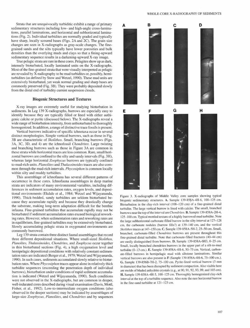
Figure 3. X-radiographs of Middle Valley core samples showing typicalbiogenic sedimentary structures. A. Sample 139-858A-4H-6, 100-125 cm.Bioturbation in the clay-rich interval (108-120 cm) of a fine-grained distalturbidite. The large vertical burrow is lined with calcite. The small, branchedburrows near the top of the interval are Chondrites. B. Sample 139-858A-2H-4,125-100 cm. Typical mottled texture of a highly burrowed mud turbidite. Notethe large subhorizontal carbonate-filled burrow in the silty interval at 127-128cm, the carbonate nodules (burrow fills?) at 139-140 cm, and the verticalSkolithos traces at 147-150 cm. C. Sample 139-858A-5H-2, 25-50 cm. Small,branched, carbonate-filled Chondrites burrows are present throughout thisfine-grained distal turbidite. Note that carbonate-filled fractures (40-44 cm)are easily distinguished from burrows. D. Sample 139-858A-6H3, 0-25 cm.Small, locally branched chondrites burrows in the upper part of a silt-to-mudturbidite (0-13 cm.). E. Sample 139-858A-4H-6, 50-75 cm. Vertical, carbon-ate-filled burrows in hemipelagic mud with siltstone laminations. Similarvertical burrows are also present in F (Sample 139-858A-4H-6, 75-100 cm.).G. Sample 139-856B-7H-2, 75-100 cm. Pyrite-lined vertical burrow (3 mmin diameter) that has been disrupted by sediment compaction. Also visible hereare molds of bladed anhydrite crystals (e.g., at 90,91, 92, 93, 99, and 103 cm).H. Sample 139-858A-4H-5, 100-125 cm. Thoroughly homogenized clay-richinterval at the top of a turbidite sequence. Also note the rare horizontal burrowin the fine-sand turbidite at 121-123 cm.
107

C.A. RIGSBY, R.A. ZIERENBERG, P.A. BAKER
Figure 4. X-radiographs of Middle Valley hemipelagic and turbiditic mudstones showing burrow tiering structure. A. Sample 139-858A-6H-3, 124-135 cm.Intensely bioturbated hemipelagic mudstone containing Skolithos (S), Chondrites (C), Planolites (P), and Zoophycus (Z) trace fossils. Note the crosscuttingrelationships between the burrows. B. Sample 139-858A-7H-1, 139-148 cm. Turbiditic mudstone with Planolites and Thalassinoides (T) burrows reworked andcut by Chondrites burrows. Also note the presence of wider, pyrite-filled, subhorizontal burrows (unidentified) in the base of the overlying turbidite.
burrowed by Chondrites alone. Further work is necessary to ade-quately document changes in oxygen level and sedimentation ratesrecorded in Middle Valley strata.
In addition to the environmental information obtained from ichno-fauna, we propose that the burrows disrupt the permeability structureof the sediments by acting as pipes for fluid migration through thesediments. Diagenetic pyrite and calcite both occur as lining andinfilling material in the burrows. Many of the burrows are visible onthe X-radiographs only because of the presence of these authigenicminerals. The burrowing obviously occurred in unconsolidated sedi-ment within several cm of the seafloor (probably up to 20 cm in somecases). Pyritization of the burrows is also interpreted to have occurrednear the sediment-water interface (see discussion below). Rarely, thelarger pyritized burrows show evidence of disruption due to compac-tion of the sediment (Fig. 3G), confirming that they were pyritizedearly in the diagenetic history of the sediment. Some of the burrow-filling calcite, however, formed later in the diagenetic history, prob-ably by in-situ precipitation from fluids migrating both vertically andlaterally through the sediment.
Diagenetic Structures and Textures
Both diagenetic carbonate and diagenetic pyrite are easily recog-nizable in the X-radiographs but were commonly overlooked duringroutine shipboard sedimentological examination. Diagenetic carbon-ate, usually in the form of intergranular cement, is recognized becauseof its low porosity relative to the surrounding siliciclastic material.Likewise, high density sulfide minerals stand out in dramatic contrastto the surrounding sediments.
Diagenetic Carbonate
Four major diagenetic carbonate morphologies are present in theLeg 139 X-radiographs: burrow-linings and fillings (discussed above),mininodules, nodules, and laths. Small (millimeter-scale), well-rounded,
spherical to slightly elliptical carbonate masses such as those seen inFigures 5A, 5B, and 5C are classified here as mininodules. Mini-nodules are common in the clay-rich intervals and differ from nodulesin size only. Nodules are typically well-rounded, irregular spheres orelongated ellipsoids. They range from 5 mm to 3 cm in their longestdiameter and occur most commonly in clay-rich intervals immedi-ately adjacent to sandy or silty turbidites. Although nodule shape andlocation can be studied via visual core examination, X-radiography isuseful for examining internal nodule structure and for determiningoverall nodule distribution. Figures 5E and 5F show typical largenodules. The nodule in Figure 5E contains lath-shaped inclusions andtextures that are reminiscent of the mininodules.
Nodules and mininodules in the upper part of the core (aboveabout 20 mbsf) are formed as a result of microbially mediated meth-ane oxidation within one or two meters of sediment-water interface.Deeper nodules and mininodules (below 20 mbsf) did not form as aresult of methane oxidation. Although their textures are similar tothose at shallower depths, their oxygen isotope compositions revealthat they formed at or near their present depths as a result of sulfatereduction of organic matter (Baker et al., this volume). It is likely thatmany of the large nodules formed as a result of continued precipita-tion and the eventual growing together of groups of mininodules.Mininodule formation may be related to the original distribution ofcarbonate microfossils in the fine-grained sediments. These hypothe-ses are currently under investigation.
Diagenetic laths are the fourth type of carbonate morphology re-vealed by X-radiography. The laths are up to 1 cm long and occur asindividual features (Fig. 5F) or as multiple inclusions in nodules (Fig.5E). Although visual core examination reveals that anhydrite laths andmolds are present in the core below 63 mbsf, we have no evidence tosuggest that the laths revealed by X-radiography are anhydrite. Theyare typically 2 to 3 times larger than the visually observed anhydritelaths and occur at much shallower depths. Pore-water chemistry in thelath-bearing intervals (Davis, Mottl, Fisher, et al., 1992) suggests thatthe laths revealed by X-rays are calcite, not anhydrite.
WHOLE-CORE X-RADIOGRAPHY OF SEDIMENTS
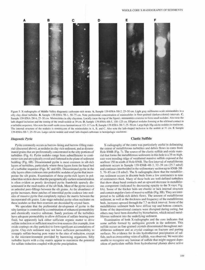
Figure 5. X-radiographs of Middle Valley diagenetic carbonate-rich strata. A. Sample 139-85 8A-5H-2, 25-50 cm. Light gray millimeter-scale mininodules in asilty clay distal turbidite. B. Sample 139-858A-7H-1, 50-75 cm. Note preferential concentration of mininodules in finer-grained (darker-colored) intervals. C.Sample 139-858A-2H-6, 25-50 cm. Mininodules in silty claystone. Locally (near the top of the figure), mininodules coalesce to form small nodules. Also note thelath-shaped inclusion and the zoning of the small nodule at 39 cm. D. Sample 139-858A-4H-5, 100-125 cm. Elliptical nodules forming at the silt/mud contact ina turbidite sequence. Also note the small-scale cross-laminations at 115-117 cm. E. Sample 139-858A-2H-7,25-50 cm. Large high-Mg calcite nodules in mudstone.The internal structure of the nodules is reminiscent of the mininodules in A, B, and C. Also note the lath-shaped inclusion in the nodule at 31 cm. F. Sample139-858A-5H-7, 25-50 cm. Large calcite nodule and small lath-shaped carbonate in hemipelagic mudstone.
Diagenetic Pyrite
Pyrite commonly occurs as burrow-lining and burrow-filling mate-rial (discussed above), as nodules in clay-rich sediment, and as dissem-inated grains that are preferentially concentrated in the silty portions ofturbidites (Fig. 6). Pyrite nodules range from submillimeter to centi-meter size and are typically ovoid and flattened in the plane of sedimentbedding (Fig. 6B). Disseminated pyrite is most common in silt-richlayers of turbidites, particularly where these layers form the basal bedof a turbidite sequence (Figs. 6C and 6D). Disseminated pyrite in thesilty layers often coalesces into poikiolitic nodules of pyrite that incor-porate the silt grains. Examination of these pyrite-rich layers in pol-ished thin section shows that the paragenetically earliest mineralizationis often evident as poorly developed pyrite framboids sparsely dis-seminated in the mud matrix of the silt beds. Most of the pyrite occursas anhedral pore-fillings between the silt grains. As the abundance ofpyrite increases, these patches of interstitial pyrite coalesce into nod-ules of massive pyrite that completely replace the matrix between theincorporated silt grains. Late-stage euhedral pyrite often nucleates onthese nodules so that their exteriors are decorated by crystal faces.
We speculate that the preferential development of pyrite in thesilty laminae is controlled by a combination of enhanced permeabilityand chemically reactive substrate. Sandy portions of the turbiditeshave adequate permeability to allow diffusion of sulfate-bearing porefluid, but apparently lack either sufficient organic matter to drivesulfate reduction or sufficient reactive iron sources (for example, ironoxide coatings on clay particles) to form significant accumulations ofpyrite. Clay-rich sediment may not have sufficient permeability toresupply sulfate-bearing pore water to the sites of reduction, exceptin the microenvironment provided by burrowing organisms. Siltyturbidite layers with a clay matrix appear to maximize the potentialfor sulfate-reduction coupled with pyrite precipitation.
Clastic Sulfide
X-radiography of the cores was particularly useful in delineatingthe extent of metalliferous turbidites and debris flows in cores fromHole 856B (Fig. 7). The source of the clastic sulfide and oxide mate-rial that forms the metalliferous sediments in this hole is a 35-m-high,east-west trending ridge of weathered massive sulfide exposed at theseafloor 150 m south of Hole 856B. The first interval of metalliferoussediment occurs in Sample 139-856B-4H-3, 32-39 cm (25.7 mbsf)and continues interbedded in the sedimentary section up to 856B-3H-5, 70-85 cm (18 mbsf). The X-radiographs show that the metallifer-.ous sediment occurs in discrete beds from a few centimeters to tensof centimeters thick. Many of these beds are well-defined turbiditesthat show sharp basal contacts and an upward decrease in metallifer-ous component (indicated by decreasing opacity to the X-rays; Fig.8A). Some of the thicker beds are chaotic or lack internal structureand contain angular clasts of massive sulfide (Fig. 8B). They are inter-preted to be sulfide-rich debris flows. The amount of metalliferoussediment, as well as the thickness and frequency of the metalliferousbeds, increases upward through the 7.7-m-thick interval. Some of themetalliferous sediment beds have diffuse top and bottom contacts.Some of the depositional contacts were disrupted during coring, butothers may have been disturbed by bioturbation, which mixed metal-liferous sediment into the underlying sediment.
Examination of both X-radiographs and the core indicates thatsome sulfide formed by authigenic growth in the sediment. Thissulfide occurs as fine-grained crystals disseminated throughout met-alliferous sediment and as crystal coatings on fracture and partingsurfaces. No evidence for in-situ hydrothermal precipitation of sul-fide, such as crosscutting veins of sulfide, was observed. We were alsounable to recognize any laminae of sulfide that might suggest depo-sition of particulate sulfide from hydrothermal plumes above active
109

C.A. RIGSBY, R.A. ZIERENBERG, P.A. BAKER
Figure 6. X-radiographs of Middle Valley cores showingtypical occurrences of diagenetic pyrite. A. Sample139-858A-7H-5, 74-100 cm. Disseminated pyrite in siltlaminations. B. Sample 139-858A-7H-4, 98-124 cm.Disseminated pyrite in silty turbidites. Note the massive pyritenodule in the lamination at 122 cm. C. Sample139-858A-8H-2, 75-103 cm. Fine-grained disseminated pyritein a laminated silty turbidite. Note the absence of pyrite in theclay-rich interval from 77-83 cm. Also note the large pyritenodule at the base of the figure. Individual, euhedral pyritegrains are clearly visible within the nodule. D. Sample139-858A-7H-3, 49-77 cm. The sandy turbidite base in theupper part of the figure is highly pyritic. Note that the onlypyrite present in the fine-grained (dark-colored) interval isburrow-fill material.
vents. All of the observed features suggest that the metalliferoussediment was transported as clastic grains to the site of deposition.
The metalliferous sediment is composed of mixtures of hematite,magnetite, pyrite, and hydrothermal smectite with less abundant chal-copyrite, sphalerite, amorphous silica, and barite. The abundance ofiron oxide and the porous and weathered nature of many of the clastssuggest that material for the metalliferous sediment formed by sea-floor oxidation and weathering of the massive sulfide deposit 150 msouth of the depositional site. The increase in both the thickness ofmetalliferous beds and in the size of sulfide clasts upward through thissection suggests that the degree of disaggregation and weatheringof the massive sulfide deposit was the primary control on the availa-bility of material for forming the redeposited metalliferous sediment.These units therefore primarily record the destruction of this seafloordeposit, not its construction. The presence of authigenic sulfide inthese sediments is interpreted to result from local sulfate reductionutilizing the abundant reactive iron-oxide component in these sedi-ments and does not appear to be an indication of local hydrothermalprecipitation of sulfide.
Hole 856B was drilled on the flank of an uplifted sediment hill.The sediment interval containing the metalliferous sediment is anom-alous because of the dipping contacts of the sediment layers (e.g.,Fig. 8) and has been interpreted as a slumped interval (Davis, Mottl,Fisher, et al., 1992). The sudden cessation of metalliferous turbiditedeposition at 18 mbsf recorded by the X-radiographs may have beencaused by the sudden uplift of this section of the seafloor above thelocal depositional basin that was receiving debris from the steepweathering ridge of massive sulfide.
B
856 Bmbsf
Debris flows
Turbidites
22 -
?4 -
Hemipelagic andturbiditic sediment
Metalliferoussediment
Figure 7. Schematic section of Core 856B (856B-3H-5, 70 cm through 856B-4H-3, 39 cm, between approximately 18 and 26 mbsf) showing the extent ofmetalliferous sediment. Samples containing metalliferous sediment thickenand coarsen upsection.
110

WHOLE-CORE X-RADIOGRAPHY OF SEDIMENTS
CONCLUSIONS
The X-radiographs taken for this study show many structures andtextures that were not observed in the core during visual examination.Much of what we see, however, is as yet unidentified because theX-radiography was done after the core was described. X-radiographsserve as a guide to our continuing studies by providing a samplingguide, by enabling us to make volume estimates of diagenetic miner-alization, and by providing a clear picture of the processes that wereresponsible for both strata! accumulation and alteration.
To be truly effective in improving core description and guidingsampling, X-radiography should be done aboard the Resolution aspart of routine core analysis.
ACKNOWLEDGMENTS
We are grateful to Chris Mato and the staff at the ODP corerepository at TAMU for assisting with core access and equipmentsetup and to the ODP photography group for helping with film selec-tion and logistics. We also thank the veterinary staff at the TAMUveterinary facility for providing access to and instruction in the use oftheir X-ray developing equipment. Funding for this study was pro-vided by a JOI/USSAC grant to Rigsby.
Figure 8. X-radiographs of Middle Valley clastic sulfide units. A. Sample139-856B-3H-6, 25-50 cm. Closely spaced metalliferous sediment turbidites.Grading is displayed by the decrease in iron oxide and iron sulfide upwardwithin each unit. Coarser turbidites also show grain-size grading, which is notapparent in the X-radiographs. Coarse clasts of massive sulfide occur at 32,39, and 44 cm. B. Sample 139-856B-3H-5, 125-150 cm. Debris flow contain-ing clasts of massive sulfide (bright) and sediment (dark). Bedding is chaoticon the scale of the core. Overlying debris flow at 70-85 cm is the uppermostunit of clastic sulfide and represents a sudden cessation of metalliferoussediment in a 7.7-m-thick sequence that coarsens and thickens upward.
REFERENCES
Berger, W.H., Ekdale, A.A., and Bryant, P.P., 1979. Selective preservation ofburrows in deep-sea carbonates. Mar. Geol., 32:205-230.
Bouma, A.H., 1969. Methods for the Study of Sedimentary Structures: NewYork (Wiley-Interscience).
Davis, E.E., Mottl, M.J., Fisher, A.T., et al., 1992. Proc. ODP, Init. Repts., 139:College Station, TX (Ocean Drilling Program).
Ekdale, A.A., Bromley, R.G., and Pemberton, S.G. (Eds.), 1984. Ichnology:Trace Fossils in Sedimentology and Stratigraphy. SEPM Short Course, 15.
Stow, D.A.V., and Wetzel, A., 1990. Hemiturbidite: a new type of deep-watersediment. In Cochran, J.R., Stow, D.A.V., et al., Proc. ODP, Sci. Results,116: College Station, TX (Ocean Drilling Program), 25-34.
Wetzel, A., and Wijayananda, N.P., 1990. Biogenic sedimentary structures inouter Bengal Fan deposits drilled during Leg 116. In Cochran, J.R., Stow,D.A.V., et al., Proc. ODP, Sci. Results, 116: College Station, TX (OceanDrilling Program), 15-24.
Abbreviations for names of organizations and publications in ODP reference lists followthe style given in Chemical Abstracts Service Source Index (published by AmericanChemical Society).
Date of initial receipt: 2 March 1993Date of acceptance: 9 September 1993Ms 139SR-224
111