7 ''lfj i
TRANSCRIPT

RECORDS ADMINISTRATION
111111111111111111111111111111 ABYY
/! ( c::_:_ 11~_,7 ''lfJ I
DP-MS-81-68 .
PREDICTION OF CENTRIFUGAL PUMP CLEANING ABILITY IN WASTE SLUDGE
by
Bernice V. Churnetski
E. I. du Pont De Nemours & Co. Savannah River Laboratory Aiken, South Carolina 29808
For presentation at the 1981 American Nuclear Society Winter Meeting at San Francisco, CA on November 29, 1981 - December 4, 1981
This paper was prepared in connection with work done under Contract No. DE-AC09-76SR00001 with the U.S. Department of Energy. By acceptance of this paper, the publisher and/or rec~p~ent acknowledges the U.S. Government's right to retain a nonexclusive, royalty-free license in and to any copyright covering this paper, along with the right to reproduce and to authorize others to reproduce all or part of the copyrighted paper.
DP-MS-81-68
PREDICTION OF CENTRIFUGAL PUMP CLEANING ABILITY IN WASTE SLUDGE*
by
Bernice V. Churnetski
E. I. du Pont De Nemours & Co. Savannah River Laboratory Aiken, South Carolina 29808
SUMMARY
Radioactive waste at the Savannah River Plant (SRP) is being transferred from older waste tanks to new, stress-relieved tanks for more effective waste management. The technology developed for waste removal involves the use of long-shaft, recirculating, centrifugal pumps (slurry pumps). Testing completed at the Savannah River Laboratory's 30-meter-diameter mock-up waste tank related the effective cleaning radius (ECR) of a slurry pump to critical pump and material characteristics. Presently, this theory is being applied to radioactive waste at SRP. However, the technology can be applied to other remote handling situations where the slurry rheology can be determined. For SRP waste, an equation of the form:
ECR a DV (p/T )l/2 0 0
was determined where D is the nozzle diameter, Vo is the average initial velocity, p is the density of the slurry, and To is the yield stress of the slurry. Using this relationship, the cleaning performance of a pump operating in any SRP sludge environment can be predicted. Specifically, yield stress and density measurements on sludge samples can be used to predict the required number and effective location for slurry pumps in actual SRP waste tanks.
* The information contained in this article was developed during the course of work under Contract No. DE-AC09-76SR00001 with the U. S. Department of Energy.
- 2 -

PREDICTION OF CENTRIFUGAL PUMP CLEANING ABILITY IN WASTE SLUDGE
BACKGROUND
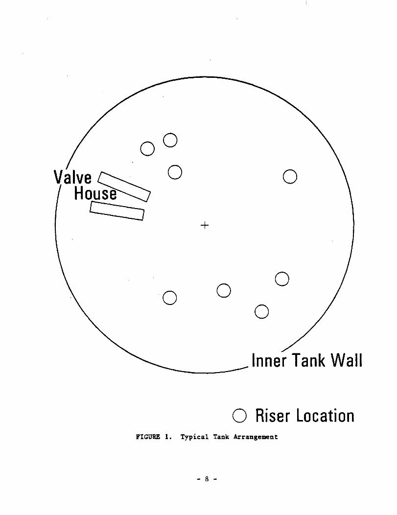
Radioactive waste at the Savannah River Plant (SRP) is being transferred from older waste tanks to new stress-relieved tanks for more effective waste management. The radioactive sludge portion of the waste consists mainly of insoluble oxides and hydroxides of iron, aluminum, and manganese. The sludge was found to be a sticky, brown, gelatinous material with particle sizes from 1 to 80 ~. It is rheologically characterized as a Bingham plastic, a material with a yield stress. Therefore, an initial force must be applied before the radioactive sludge will become a pumpable slurry. The removal of this sludge from waste tanks is complicated by the presence of a network of cooling coils. This prohibits the use of any blade type agitator. Also, access to the waste tanks is limited to riser locations (Figure 1). The riser locations for slurry pumps in old waste tanks have a diameter of 0.61 meters whereas those of new waste tanks have a diameter of 0.92 meters. The technology developed for waste removal under these constraints involves the use of long-shaft, recirculating, centrifugal pumps (slurry pumps).
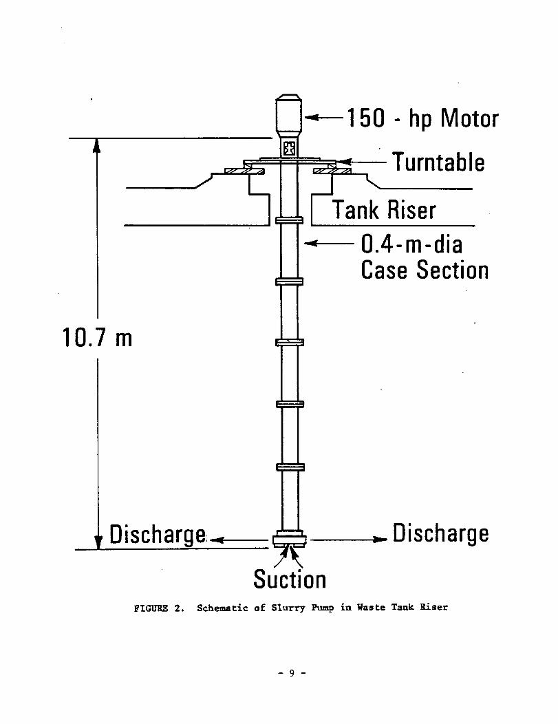
The slurry pump (Figure 2) has a bottom suction and two opposing discharge nozzles. The immersion of the pump in the sludge layers allows a recirculating mixture of sludge to serve as the feed for the pump. The slurry pump is mounted on a turntable allowing the entire pump to rotate between 1/5 and 1/2 rpm. This creates a circular cleaning pattern defined as the effective cleaning radius (ECR).
This effective cleaning radius ~s a measure of the cleaning ability of the pump. It is defined as the distance from the centerline of the pump to the point where settled sludge is not resuspended (Figure 3).
Background Theory
Initial studies to predict the effective cleaning radius of the slurry pump emphasized the velocity of the jet. 1 Two design factors are considered important for a liquid jet to resuspend sludges - the turbulence level of the jet stream and the impact of the stream on the sludge. Both of these design parameters are dependent on the velocity of the stream. Also the ability to keep
- 3 -

the solids fluidized is directly related to the velocity. Therefore, the velocity of the jet was taken as the measure of the slurrying efficiency of the jet. With this emphasis, submerged jet theory was applied to the nozzle of the pump.
From submerged jet theory, when a turbulent, high velocity, free jet of fluid is discharged from a round opening, it both entrains fluid and expands (Figure 4). Most of the slurrying action and entrainment takes place in the region of establish flow. This region begins approximately eight nozzle diameters from the nozzle outlet. The distribution of velocity along the phase jet with no density gradient is given by:2
v X
using r/x = tan (1/26)
Vx = ~ V oDe -c2[ tan(l/ 29)] 2
( 1)
( 2)
where c 1 and c2 are constants equal to 40 and 6.2 respectively, x is the distance from the nozzle, V0 is the initial discharge velocity, Vx is the velocity of the stream at distance X, D is the nozzle diameter, and 9 is the jet angle.
The above theory shows that the velocity at any point 1n the region of established flow is directly proportional to the D V0 product. Thus, two pumps operating in the same medium with the same D V
0 product should produce the same velocity distribution
and therefore have the same cleaning ability (ECR).
This direct proportionality relationship of the effective cleaning radius to the D V0 product was verified in previous testing.l However, because of different processing parameters, such as amount of time in the tank, the rheological properties of the sludges differ between tanks. Therefore, a study was initiated to determine how the ECR relates to critical pump and material characteristics. This will then allow estimation of the ECR based on sludge samples obtained from the tanks.
- 4 -
EXPERIMENTAL
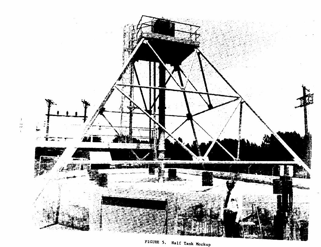
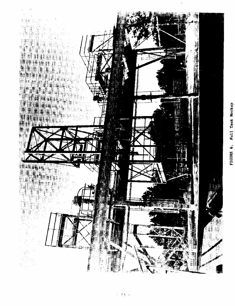
Testing was conducted in full and half tank mock-up facilities using kaolin clay slurries. Initial testing was done in the half tank facility (Figure 5) using 30 wt % kaolin. As larger capacity pumps were developed, the geometric configuration of the half tank facility began to interfere with accurate ECR measurements. Present testing is done in a full tank mock-up facility (Figure 6). The full tank mock-up is 85 ft in diameter and 8 ft high. The overhead gantry has the capability of running six slurry pumps. To simulate two feet of waste in the full tank mock-up approximately 130 tons of dry kaolin clay are required.
Kaolin clay slurries are used to simulate the actual radioactive sludge because (1) it has rheological properties similar to chemically simulated sludge, (2) different rheology can be simulated by varying the water content of the slurry, and (3) the large quantities necessary for testing make the kaolin clay both cost effective and ecologically acceptable.
Two variable speed pumps designed for different D V0 products were used for testing. The specifications of the two pumps are given in Figure 7. Kaolin clay slurry concentrations varied between 17 and 22 wt % kaolin during testing.
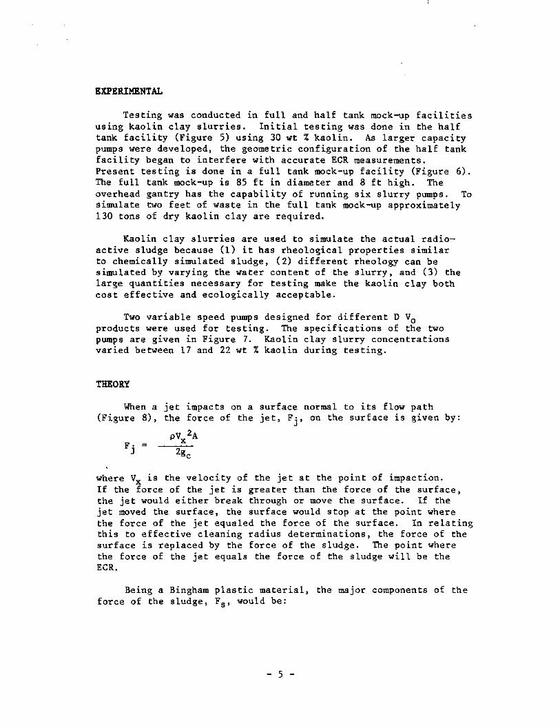
THEORY
When a jet impacts on a surface normal to its flow path (Figure 8), the force of the jet, Fj, on the surface is given by:
F· = J
pV 2A X
where Vx is the velocity of the jet at the point of impaction. If the force of the jet is greater than the force of the surface, the jet would either break through or move the surface. If the jet moved the surface, the surface would stop at the point where the force of the jet equaled the force of the surface. In relating this to effective cleaning radius determinations, the force of the surface is replaced by the force of the sludge. The point where the force of the jet equals the force of the sludge will be the ECR.
Being a Bingham plastic material, the major components of the force of the sludge, Fs, would be:
- 5 -

(4)
where T0 is the yield stress and A is the Area. Equating the two forces, equation (3) with equation (4):
F· = F J s
pV 2A X
~---- = T A ~c o
(5)
(6)
Substituting Vx from equation (2) the distance x can be obtained:
X = (7)
RESULTS
Data from tests with slurry concentrations between 17 and 22 wt % kaolin and 1/3 rpm rotation are plotted in Figure 9. The line drawn is from equation (7) for a twenty wt % kaolin slurry. The correlational factor, r, for the fit of this line to the data is approximately 0.92. This is largely due to the fluctuation of slurry concentration used during testing (17 to 22 wt %).
Figure 10 represents data taken in the half tank mock-up facility.l Testing was done with a 30 wt% kaolin slurry. The line drawn represents substitution of the values for a 30 wt % kaolin slurry into equation (7). The correlational factor, r, for the fit of this set of points to the line, is 0.98. This deviation was minimal because the tank was emptied after each test and kaolin was added to achieve exactly a 30 wt % slurry.
CONCLUSION
This study verified the D V0 proportionality and related material characteristics of a Bingham plastic slurry to pump performance in sludge. The use of this theory for effective waste removal is in progress at the Savannah River Plant and can be expected to extend into other situations where toxic or unwieldy substances are to be removed from storage tanks.
- 6 -
REFERENCES
1. H. H. Elder. Demonstration of Radioactive Sludge Removal from SRP Storage Tanks. 20th Annual AIChE Meeting, New York (November 1977).
2. J. H. Perry, Ed. Chemical Engineers Handbook, 5th ed. pp.S-19, McGraw-Hill Book Co., New York (1973).
- 7 -
0
+
0 0 0
0
Inner Tank Wall
0 Riser Location FIGURE 1. Typical Tank Arrangement
- 8 -
~
~ 150 - hp Mo - tor -~
Turntabl -. e L -
Tank Riser ~ 0.4-m-dia
Case Secti on
10.7 m
ischarge~ ~ ~ Discharg 7\
e D
Suction FIGURE 2. Schematic of Slurry Pump in Waste Tank Riser
- 9 -
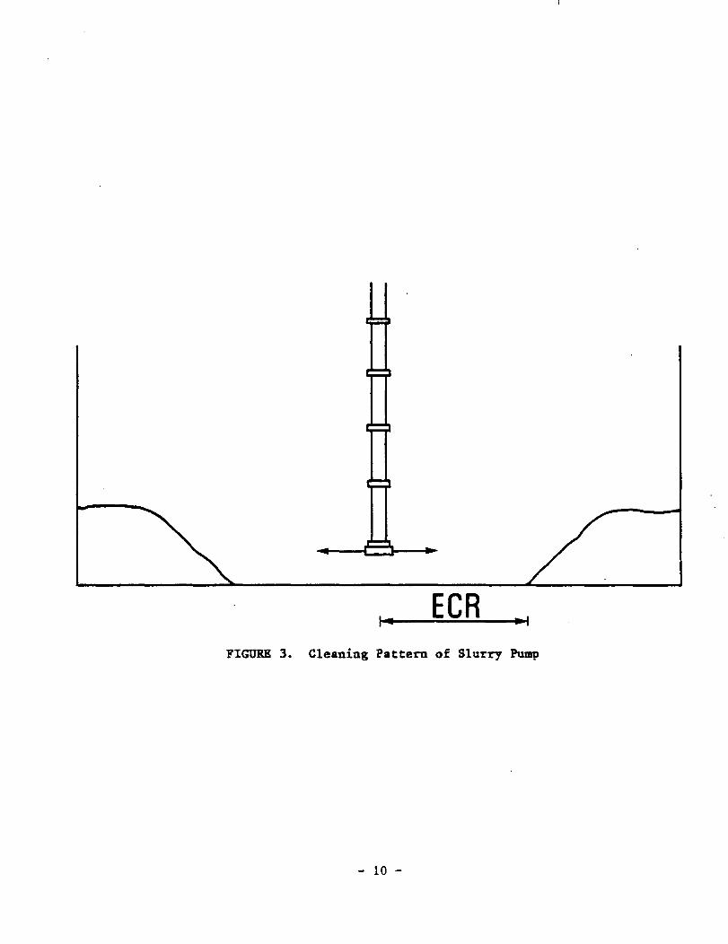
ECR FIGURE 3. Cleaning Pattern of Slurry Pump
- 10 -

D
~X
e
~----....... ~ REGION OF ESTABLISHED FLOW
FIGURE 4. Configuration Turbulent Free Jet
- 11 -
-,..
FIGURE 5. Half Tank Mockup
. ~
I

Capacity, m3/min
Nozzle Diameter, em
-· RPM
Pump OD, em
D V0
Product, at/sec
Clening Radius, m (in 20 wt % slurry)
Standard Ptunp
4.54
3.81
1760
57.15
1.26
7.62
Increased Capacity Ptunp
15.14
7.62
2200
85.725
2.11
12.2
FIGURE 7. Specifications for Slurry Pumps Tested
- 14 -

Fj
JET~
FIGURE 8. Impact of Jet on a Surface
- 15 -

2.0
(.) C1) 1 . Cl)
' N
E --... ..-
(.) 1.0 :;::, -c 0 ~
c.. 0
> 0.5 - Standard Pump c:l
e Increased- Capacity Pump
0. .~ 0.0_ 3.0 6.0 9.0 12.0 15.0
Effective Cleaning Radius, m FIGURE 10. Half Tank Mockup Results
- 16 -

2.
(.) C1)
1 . Cl.)
' N
E ... .....,
(.)
1 . ::::s -o 0 ~
c.. 0
> 0. 0
3.0 0
Effective Cleaning Radius, m FIGURE 9. Full Tank Mockup Results
- 17 -