7 chassis and -...
TRANSCRIPT

Engineering Services, Inc..
7 Chassis and Suspension Concepts
ULSAB-AVC – PES Engineering Report June 2001
Chapter 7Page 1
7.1 BACKGROUND
Chassis and suspension concepts for ULSAB-AVC feature a range of high strength steels and new technologies such as TWBs for wishbones and tailor tube hydroforming.
The principal goal for the development of front and rear suspensions of the ULSAB-AVC con-
cept vehicles (C-Class and PNGV-Class) was the design of steel intensive lightweight suspen-
sion. Conventional and new steel materials should be applied together with their related
manufacturing processes and assembly technologies. The goal was addressed within the
overall approach of designing the lowest overall mass of the complete vehicles rather than
the lightest possible suspension concepts. An alternative, lighter weight suspension system
with low mass may not contribute to achieving the lowest overall vehicle mass because they
could cause mass increases in other components (e.g. body structure).
7.2. Approach
Although the ULSAB-AVC Program involves the development of two vehicle concepts, with
either a diesel or gasoline engine variation, it was necessary to develop similar suspensions
for both C-Class and PNGV-Class vehicles. Of course tuning components (e.g. springs,
dampers) would have to be specific to each vehicle to accommodate the range of wheel loads
in conjunction with vehicle mass. The final set-up would have to be tuned on the test tracks.
Components were calculated, with the resulting forces of the load cases described in Section
7.8.2. in terms of stress, and designed accordingly. Specified carry-over parts were adapted
respecting the different mass and loads of the ULSAB-AVC vehicles.
The emphasis on safety was, in some respects, a principle driver of the concept design of
the body structure. This decision required that a significant deformable distance be achieved
between the vehicle skin and the shock tower location under the hood and influenced the
shock and spring location. Therefore, the selection of the front suspension type took into
account anticipated pedestrian safety.

Engineering Services, Inc..
7Ch
assi
s an
d Su
spen
sion
Con
cept
s
ULSAB-AVC – PES Engineering Report June 2001
Chapter 7Page 2
In addition, the front end module had to be designed as a system including
engine, transmission and front suspension attached to a front subframe in order
to enable assembly and disassembly as one unit without the requirement to
realign the suspension after assembly.
A critical assessment of emerging non-steel chassis technologies (e.g. ceramic
brake discs) was undertaken and their use was considered in relation to overall
program objectives whenever a significant benefit would result from their use.
The impact on manufacturing cost and specified mass production (> 225,000
units/year) was also considered.
7.3. Scope of Work
The scope of work for the development of the suspension concepts included the
following tasks:
• Assessment of benchmarking results of chassis components of the
Ford Focus and Peugeot 206 from the Benchmarking Report (found
in the ULSAB-AVC Consortium Document Technical Transfer Dispatch
#3) and publicly available data for overall target setting
• Evaluation of suspension mass
• Calculation of chassis components, mass, curb weight, gross weight
and axle load
• Mass estimation of chassis components
• Preliminary consideration of front and rear suspension concepts
• Concept design of front and rear suspensions with regard to mass
reduction of suspension components and subframe components
• Definition of suspension kinematics
• Selection of steering system concept
• Selection of engine mounting concept (without evaluation of bearing
stiffness)
• Selection of carry-over brake system
• Calculation of axle loads and calculation of the forces and torque on
the components of the suspension
• Calculation of component load and forces
• Selection of component manufacturing concept (e.g. stamping, hydro-
forming)
• Design Layout of suspension components

Engineering Services, Inc..
7Ch
assi
s an
d Su
spen
sion
Con
cept
s
ULSAB-AVC – PES Engineering Report June 2001
Chapter 7Page 3
• FEM-calculation to analyze the suspension component design layout
(e.g. dimensions, materials)
• Incorporation of FEM-calculation results into suspension designs
• Definition of drive shafts
• Assessment of manufacturing and assembly costs
7.4. Benchmarking Data and Target Setting
Prior to the start of the concept design phase, benchmarking data for mass of
various suspension systems was gathered to set the targets for both C-Class and
PNGV-Class vehicle suspensions. These were developed based on experience
and engineering judgement and are displayed as total mass targets in Table
7.4-1 along with the benchmarking data of a Ford Focus and a Peugeot 206,
which was reviewed.
Component Name Ford Focus (kg)
Peugeot 206 (kg)
ULSAB-AVC Targets**
C-Class and PNGV-Class (kg)
Front Suspension incl. subframe 55.05 53.79 50.0
Rear Suspension incl. subframe 55.04 42.13 42.0
Pedal system 7.51 7.82 5.7Wheels with tires 84.85 67.81 46.2Brake system 39.59 45.55 38.5Steering system 19.39 16.86 16.0Others 2.84 2.87 n/aTotal Mass* 264.26 236.82 198.5
* Total mass of suspension does not include drive shafts** For cost reduction and as a result of the small difference in total vehicle mathe decision was made that both vehicles will share the same suspension withexception of tuning parts
Table 7.4-1 Suspension benchmarking data and ULSAB-AVC suspension targets
Using these component mass targets, the curb and gross weight of the vehicles
were calculated.

Engineering Services, Inc..
7Ch
assi
s an
d Su
spen
sion
Con
cept
s
ULSAB-AVC – PES Engineering Report June 2001
Chapter 7Page 4
7.5. First Assumptions for FEM-Calculation
The following assumptions were used as input parameters for the initial load
calculation:
7.5.1. Suspension Load Input Parameters and Assumptions
Table 7.5.1-1 Axle load input parameters
Front suspension
Rear suspension Weight Front
suspensionRear
suspension Weight
Curb weight (kg) n/a n/a 998 592 485 1077Design load (kg) n/a n/a 1253 n/a n/a 1302Gross weight* (kg) 730 713 1448 741 836 1577Maximum payload (kg)n/a = not applicable* at wheel center
C-Class PNGV-Class
450 500
7.5.2. Kinematics Layout Assumptions For the first kinematics layout, the following assumptions were used.
Table 7.5.2-1 Kinematics layout assumptions
Dimension Front Suspension Rear Suspension
Wheel base C-Class/PNGV-ClassTrack 1537 mm 1540 mmHeight of center of gravity at curb weightWheel (tires/rims)*Wheel travel + 90 / -105 mm +/- 105 mmSteering rack travel
* optional 185/60 R15 5.5Jx15
2950 mm / 3035 mm
550 mm
175/65 R14 5J x 14
+/- 79 mm

Engineering Services, Inc..
7Ch
assi
s an
d Su
spen
sion
Con
cept
s
ULSAB-AVC – PES Engineering Report June 2001
Chapter 7Page 5
7.6. Front Suspension
7.6.1. Concepts Considered
7.6.1.1. McPherson PrincipleThe first front suspension considered and assessed for its suitability in the
ULSAB-AVC vehicle concepts was a McPherson front suspension. It was consid-
ered because of its good balance of drive-ability (handling and comfort), mass
and cost. A principle layout of a McPherson’s front suspension is illustrated in
Figure 7.6.1.1-1.
Figure 7.6.1.1-1 McPherson principle layout
The main reasons the McPherson concept was not selected for the ULSAB-AVC
vehicle were:
• Strut attachment points lead to a high shock tower, which is located
too close to the outer vehicle skin (e.g. hood) and will not provide suf-
ficient space in the event of pedestrian impact (see Figure 7.6.1.1-2
on next page)
• Concept requirement of a powertrain/suspension module with advan-
tages in assembly and disassembly, cannot be met. Suspension has
to be aligned after disassembly and cannot preset prior to assembly
in final assembly line.

Engineering Services, Inc..
7Ch
assi
s an
d Su
spen
sion
Con
cept
s
ULSAB-AVC – PES Engineering Report June 2001
Chapter 7Page 6
Figure 7.6.1.1-2 McPherson suspension with section cuts through the body structure
7.6.1.2. Double Wishbone PrincipleThe next system, which was considered for implementation into the ULSAB-AVC
Program was a double wishbone front suspension concept in various configura-
tions.
7.6.1.2.1. Double Wishbone with Coil SpringTwo solutions for the double wishbone with coil spring were considered, but
rejected– first, a double wishbone suspension with a spring strut and next, with a
separated damper and coil spring. In the first case using a spring strut, a pack-
age investigation showed insufficient clearance between the other suspension
components. The only feasible position was to package the coil spring above the
wheel, which resulted in a similar position (at the upper shock absorber point)
to the McPherson principle; close to the outer skin of the hood. In the second
case, placing the coil spring beside the wheel and packaging the damper in a
different position to lower the upper attachment point of the shock absorber
was not practical due to insufficient clearance.

Engineering Services, Inc..
7Ch
assi
s an
d Su
spen
sion
Con
cept
s
ULSAB-AVC – PES Engineering Report June 2001
Chapter 7Page 7
7.6.1.2.2. Double Wishbone with Torsion BarsAnother possibility to lower the upper mounting point of the damper was inves-
tigated using torsion bars. In Figure 7.6.1.2.2-1, both possible positions of the
torsion bar are shown (upper wishbone and lower wishbone). Either torsion bar
locations could cause passenger compartment intrusion in frontal crash acci-
dents, increasing the risk of leg injury to passengers and therefore, this suspen-
sion concept was not selected.
Figure 7.6.1.2.2-1 Possible locations of torsion bar
7.6.1.2.3. Double Wishbone with Transverse Leaf Spring PrincipleSince packaging of the coil spring and torsion bar were not possible, a trans-
verse leaf spring was investigated. The double wishbone concept (see Figure
7.6.1.2.3-1) with transverse leaf spring showed the most potential for packag-
ing, as well as achieving mass targets. Although this concept does not represent
the lowest suspension mass, at lowest cost, it was selected as the most promis-
ing front suspension concept for the overall vehicle concept.

Engineering Services, Inc..
7Ch
assi
s an
d Su
spen
sion
Con
cept
s
ULSAB-AVC – PES Engineering Report June 2001
Chapter 7Page 8
Figure 7.6.1.2.3-1 Double wishbone with transverse leaf spring
7.7. Front End Module
The package studies highlighted the benefits of a front end module made of a
subframe with engine, wishbones, steering knuckle and damper, steering gear-
box and tie rods, transverse leaf spring and the cooling system (radiator and
intercooler). This front end module would allow ease of assembly during vehicle
manufacture, as well as disassembly for maintenance or repair over the vehicle
life.
Figure 7.7-1 Front end module bottom view

Engineering Services, Inc..
7Ch
assi
s an
d Su
spen
sion
Con
cept
s
ULSAB-AVC – PES Engineering Report June 2001
Chapter 7Page 9
7.7.1. Engine Mount ConceptsFor the selection of the engine mount system, manufacturing feasibility, func-
tion and comfort had to be considered. Three point and four point engine mount
concepts were considered
A four-point engine mount has the advantage that only small support brackets
are necessary to attach the engine mount bearings. Additionally, these brackets
can be placed close to the subframe tube as shown in Figure 7.7.1-1. Another
advantage of this system is the reduced movement of the powertrain.
Figure 7.7.1-1 Four-point engine mount concept bottom view
7.7.1.1. Selected Engine Mount ConceptAs an alternative to the four-point engine mount concept, a three-point engine
mount system as shown in Figure 7.7.1.1-1 was investigated for potential of
implementation into the subframe. Compared to the four-point engine mount
system, a three-point engine mount system shows superior acoustic behavior
when the bearings are carefully placed. In the three-point engine mount con-
cept, two bearings absorb the static loads of the powertrain and are therefore,
located close to its center of gravity of powertrain. The third bearing functions

Engineering Services, Inc..
7Ch
assi
s an
d Su
spen
sion
Con
cept
s
ULSAB-AVC – PES Engineering Report June 2001
Chapter 7Page 10
as a torque support. With a three-point engine mount concept, tuning of the
bearings becomes easier. A cross beam has to be provided for the rear mount
to increase lateral stiffness and increases the subframe mass.
Figure 7.7.1.1-1 Three-point engine mount concept bottom view
Figure 7.7.1.1-2 Selected three-point engine mount system

Engineering Services, Inc..
7Ch
assi
s an
d Su
spen
sion
Con
cept
s
ULSAB-AVC – PES Engineering Report June 2001
Chapter 7Page 11
7.7.1.2. Engine Mount BracketsThe front engine mount brackets are assemblies made from square sections
with a material thickness of 2.5 mm and two brackets, one for the attachment to
the engine and one for the attachment to the subframe. DP 350/600 material
was selected for the brackets. The rear bracket is produced out of bent sheet
steel.
Figure 7.7.1.2-1 Engine mount brackets
Table 7.7.1.2-1 Engine mount bracket parts list
Part Number
Material Thickness
[mm]Material Type Mass [kg]
1 4.0 DP 350/6002 2.5 DP 350/6003 5.0 DP 350/6004 7.0 DP 350/6005 2.0 DP 350/6006 4.0 DP 350/600
Engine mounting bracket rear LH 7 7.0 DP 350/600 0.37Engine mounting bracket rear RH 8 7.0 DP 350/600 0.37
2.596
1.047
0.809
Total mass engine mounting brackets [kg]
Engine mounting bracket LH
Engine mounting bracket RH

Engineering Services, Inc..
7Ch
assi
s an
d Su
spen
sion
Con
cept
s
ULSAB-AVC – PES Engineering Report June 2001
Chapter 7Page 12
The forces on the brackets were calculated considering the following load
cases:
Table 7.7.1.2-2 Load case
Acceleration g
Vertical acceleration 3.4
Lateral acceleration 1.0
Longitudinal acceleration 0.45
Acceleration rearward 0.4
Static 0
In the FEM-calculations, the maximum force calculated on the two mounts
located on the side of the engine was 5500 N in z-direction (vertical). For the
rear engine mount, maximum forces of 2636 N in z-direction and -985 N in
x-direction (longitudinal) were calculated with insignificant forces in y-direction.
These forces were calculated using the mass of the d iesel engine. The same
parts are used for the gasoline engine, which would generate lower forces due
to its lower mass.
Figure 7.7.1.3-2 FEM calculation results engine mount brackets
The FEM-calculations shown in Figure 7.7.1.3-2 predict a stress level of about
300 MPa in the area of the welding seam. These areas would be optimized in
a detailed design phase.
Engineering Services, Inc..
7Ch
assi
s an
d Su
spen
sion
Con
cept
s
ULSAB-AVC – PES Engineering Report June 2001
Chapter 7Page 13
7.8. Double Wishbone Front Suspension
As previously mentioned, a double wishbone front suspension was selected
for implementation in the ULSAB-AVC vehicle concept (see Section 7.6.1.2.3).
Under the given boundary conditions, including the modular assembly approach,
the task was to create a front suspension layout, which was compatible with the
other package requirements.
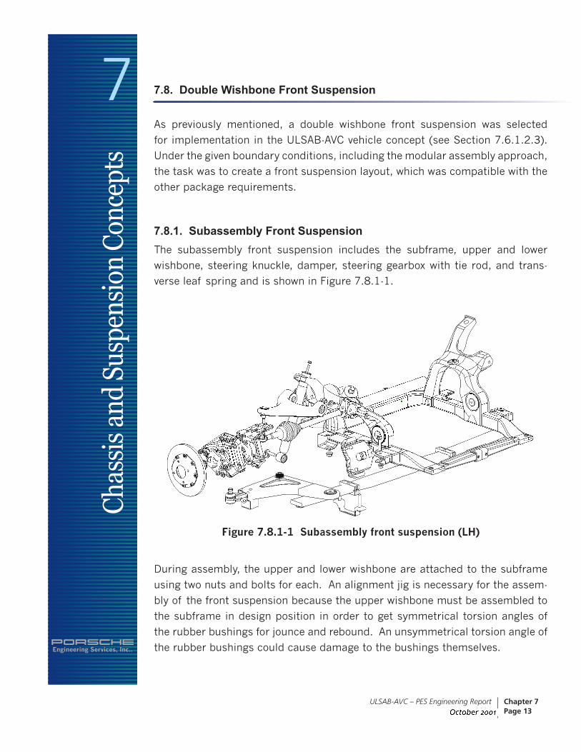
7.8.1. Subassembly Front Suspension The subassembly front suspension includes the subframe, upper and lower
wishbone, steering knuckle, damper, steering gearbox with tie rod, and trans-
verse leaf spring and is shown in Figure 7.8.1-1.
Figure 7.8.1-1 Subassembly front suspension (LH)
During assembly, the upper and lower wishbone are attached to the subframe
using two nuts and bolts for each. An alignment jig is necessary for the assem-
bly of the front suspension because the upper wishbone must be assembled to
the subframe in design position in order to get symmetrical torsion angles of
the rubber bushings for jounce and rebound. An unsymmetrical torsion angle of
the rubber bushings could cause damage to the bushings themselves.

Engineering Services, Inc..
7Ch
assi
s an
d Su
spen
sion
Con
cept
s
ULSAB-AVC – PES Engineering Report June 2001
Chapter 7Page 14
The upper wishbone controls the wheel camber and castor angle and also sup-
ports the damping and spring forces. The wishbones are attached to the steer-
ing knuckle at their outer edges.
The steering knuckle is made of two steel stampings, a 2nd generation wheel
bearing, a brake caliper, two spacer sleeves and attachment brackets for the
upper and lower wishbone and steering rod. The wheel hub is pressed into the
wheel bearing and attached to the outer joint of the drive shaft. The brake disc
completes the wheel hub assembly.
The steering gearbox, including the steering rods, is attached to the front of the
subframe and the outer ball joints on the steering rods are attached to the steer-
ing knuckle. A transverse leaf spring is attached from below, with two brackets
to the underside of the subframe. The leaf spring is loaded by attachment to
the lower wishbone near the outer ball joint. The damper’s lower attachment
point is the outer ball joint housing of the lower wishbone and its upper attach-
ment point is the subframe.
7.8.1.1. Kinematics LayoutThe concept for the kinematics layout was made to reach the following charac-
teristics, which are shown in Table 7.8.1.1-1:
Table 7.8.1.1-1 Kinematics results
Track 1542 mm Track change 1.19 mm/cmToe in 10' Toe in change 3.4'/cmCamber -0.50 deg Camber change -0.1deg/cmKingpin offset -7.7 mm Kingpin inclination 15 degCastor angle 2 degCastor offset 23 mm Castor offset in wheel center 14 mmRoll center height 44 mm Spring rate rel. to wheel center 19 N/mmSpring rate 30 N/mm Damper ratio 0.74
The kinematics characteristics are based on existing vehicles currently on the
market. To achieve a safe and stable driving behavior, the kinematics charac-
teristics were tuned towards an understeering behavior. This kinematics layout
should be validated in tests using ULSAB-AVC prototype vehicles and will likely

Engineering Services, Inc..
7Ch
assi
s an
d Su
spen
sion
Con
cept
s
ULSAB-AVC – PES Engineering Report June 2001
Chapter 7Page 15
be changed during the development process. The elastokinematic behavior is
also important for the vehicle response during maneuvers and must be tuned.
The ULSAB-AVC design concept layout allows for such variations of hardpoints
and mounting stiffness, which were considered in the package development for
future tuning as described above.
In general, two of the most significant kinematics characteristics are the change
of toe-in and camber in relation to wheel travel and are shown in Figure
7.8.1.1-1.
Figure 7.8.1.1-1 Toe in and camber characteristics of the front suspension
The elastokinematic behavior (e.g. longitudinal compliance) of the suspension
is not specified here since it is dependent on results of vehicle dynamic tests.
There is enough package space in the area of the rubber bushing locations
for optimization of the elastokinematic behavior by changing the shape of the
rubber bushings, if necessary.
7.8.2. Front Suspension Components Load DistributionThe load distribution of the front suspension components had to be taken into
account for the design of the front suspension. The load distribution is a prod-
uct of vehicle mass and the resulting wheel loads (see Table 7.5.1-1), as well as
the different forces resulting from steady state driving maneuvers. The maneu-
vers and resulting accelerations considered are shown in Table 7.8.2-1. In addi-
tion, a factor of 1.5 for safety was considered. The maneuver "curbstone push"

Engineering Services, Inc..
7Ch
assi
s an
d Su
spen
sion
Con
cept
s
ULSAB-AVC – PES Engineering Report June 2001
Chapter 7Page 16
is a misuse load case for the front suspension. This load case describes a
vehicle standing with two wheels directly besides a curbstone and the vehicle
will be pushed from the curbstone by turning the steering wheel slowly.
These maneuvers create the tire forces acting on tire contact area. The forces
are transformed into forces and torques in the wheel center and distributed to
each component of the suspension by using an elastokinematic program and
also taking the wheel travel into account. The resulting values of reaction forces
and torque for each component of the suspension are used as load input in the
FE-models for part stress analysis and can be found in Appendix - Section 4.3.
Table 7.8.2-1 Maneuvers and accelerations taken into account
Combined load cases can be analyzed by superposing the results of the indi-
vidual FEM-calculations. If the stress levels of the components are in an uncriti-
cal range, in most cases, the stiffness of the suspension components are also in
an uncritical range. The design is mostly determined by the misuse loads.
7.8.3. Subframe Design ConceptThe subframe (see Figure 7.8.3-1) is designed to transmit the forces from the
suspension into the body structure while suppressing the acoustic excitation of
the body structure by the suspension. With the selection of rigid attachment of
the subframe, the subframe stiffness is an important contributor to the rigidity
of front suspension and body structure system. The square section of the tube
was chosen to get the best stiffness for the support of the vertical and lateral
forces from the front bearing of the lower wishbones and the leaf spring and
the rear bearing of the lower wishbones and the engine mounts. These spring
Manuever Acceleration (g)Vertical push Vertical acceleration 3.4Steady state cornering Lateral acceleration 1.0Braking forward Longitudinal deceleration -1.0Braking rearward Longitudinal deceleration 0.9Acceleration Longitudinal acceleration 0.45Curbstone push (front axle Static 0

Engineering Services, Inc..
7Ch
assi
s an
d Su
spen
sion
Con
cept
s
ULSAB-AVC – PES Engineering Report June 2001
Chapter 7Page 17
forces are supported in the tube and therefore, the console, which is designed
as a closed section supports the forces of the shock absorber to provide high
stiffness and transfers the loads into the body structure. The subframe design
was developed in an iterative process with crash analysis.
Figure 7.8.3-1 Subframe design layout

Engineering Services, Inc..
7Ch
assi
s an
d Su
spen
sion
Con
cept
s
ULSAB-AVC – PES Engineering Report June 2001
Chapter 7Page 18
The subframe is manufactured from a hydroformed tube with a stamped steel
cross member welded at the rear. This cross member functions as an attach-
ment for the rear torque support of the engine mount. Two brackets for attach-
ment of the cooling unit and two sleeves for attachment of the steering gearbox
are welded to the front of the subframe. On each side, the support for the lower
wishbone is made of two deep drawn steel brackets, which are welded to the
tube. The transverse leaf spring clamp is attached by projection welding nuts
inside of the tube through access holes in the upper side of the tube. To attach
the upper wishbone, shock absorber and engine mount, a console made of two
steel stampings is welded onto the tube.
To attach the complete subframe to the body structure, four (4) attachment
points (A,B,C,D), two (2) located in the console and two (2) located in the rear
end of the hydroformed tube, are defined. The attachment points of the sub-
frame to the body structure and the attachment points of the suspension com-
ponents are shown in Figure 7.8.3-2.

Engineering Services, Inc..
7Ch
assi
s an
d Su
spen
sion
Con
cept
s
ULSAB-AVC – PES Engineering Report June 2001
Chapter 7Page 19
Figure 7.8.3-2 Subframe attachment points

Engineering Services, Inc..
7Ch
assi
s an
d Su
spen
sion
Con
cept
s
ULSAB-AVC – PES Engineering Report June 2001
Chapter 7Page 20
7.8.3.1. FEM-Calculation of the SubframeThe FEM-calculations of the subframe were made by superposing the suspen-
sion loads, as well as the engine loads. The results for the most significant load
cases are shown in Figure 7.8.3.1-1 through Figure 7.8.3.1-5 and predict only
small areas with higher stress levels. One of these areas is the front attachment
point of the console to the body and the front attachment of the console to the
tube for the load case "vertical push." The other area is the rear cross member
for the load case "acceleration." The stress level for the load case "vertical push,"
shown in A, is caused by the forces to the attachment of the shock absorber. It
can be reduced by designing a smoother transition from the attachment point
to the structure of the console. The stress level in B would also be reduced by
redesigning this area to the structure of the console. For the load case "accelera-
tion," the stress level can be reduced by optimizing the transition from the rear
engine mount to the crossmember. These design changes could be introduced
in a further development phase.
Figure 7.8.3.1-1 FEM-calculation subframe load case vertical push

Engineering Services, Inc..
7Ch
assi
s an
d Su
spen
sion
Con
cept
s
ULSAB-AVC – PES Engineering Report June 2001
Chapter 7Page 21
Figure 7.8.3.1-2 FEM-calculation subframe steady state cornering
Figure 7.8.3.1-3 FEM-calculation subframe braking forward

Engineering Services, Inc..
7Ch
assi
s an
d Su
spen
sion
Con
cept
s
ULSAB-AVC – PES Engineering Report June 2001
Chapter 7Page 22
Figure 7.8.3.1-4 FEM-calculation subframe results maximum acceleration
Figure 7.8.3.1-5 FEM-calculation subframe results curbstone push
Engineering Services, Inc..
7Ch
assi
s an
d Su
spen
sion
Con
cept
s
ULSAB-AVC – PES Engineering Report June 2001
Chapter 7Page 23
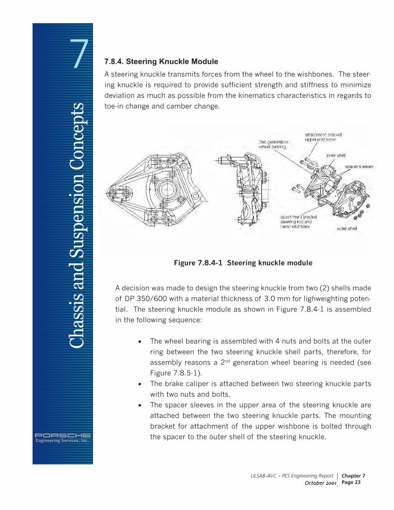
7.8.4. Steering Knuckle ModuleA steering knuckle transmits forces from the wheel to the wishbones. The steer-
ing knuckle is required to provide sufficient strength and stiffness to minimize
deviation as much as possible from the kinematics characteristics in regards to
toe-in change and camber change.
Figure 7.8.4-1 Steering knuckle module
A decision was made to design the steering knuckle from two (2) shells made
of DP 350/600 with a material thickness of 3.0 mm for lighweighting poten-
tial. The steering knuckle module as shown in Figure 7.8.4-1 is assembled
in the following sequence:
• The wheel bearing is assembled with 4 nuts and bolts at the outer
ring between the two steering knuckle shell parts, therefore, for
assembly reasons a 2nd generation wheel bearing is needed (see
Figure 7.8.5-1).
• The brake caliper is attached between two steering knuckle parts
with two nuts and bolts.
• The spacer sleeves in the upper area of the steering knuckle are
attached between the two steering knuckle parts. The mounting
bracket for attachment of the upper wishbone is bolted through
the spacer to the outer shell of the steering knuckle.

Engineering Services, Inc..
7Ch
assi
s an
d Su
spen
sion
Con
cept
s
ULSAB-AVC – PES Engineering Report June 2001
Chapter 7Page 24
• The mounting bracket for the attachment of the lower wishbone and
the steering rod is manufactured as a forged steel part. This part, with
its relatively high mass, is needed for strength in the load “curbstone
push”.
Several components, including the wheel bearing, spacer sleeves, mounting
attachment for the upper wishbone, wheel hub and brake disc, are identical for
both left and right hand sides of the steering knuckle module. The steel steering
knuckle parts, the brake caliper and the attachment bracket for the steering rod
and the lower wishbone, are mirror-imaged parts from left to right.
7.8.4.1. FEM-Calculation Steering Knuckle Version 1The initial FEM-calculation steering knuckle outer and inner shell (variation 1)
using the resulting forces from the considered load cases (see Section 7.8.2
and Appendix - Section 4.3) are shown in Figure 7.8.4.1-1 for the outer steel
shell and in Figure 7.8.4.1-2 for the inner steel shell parts. It is important to
recognize that the red colored areas around the points of constraint (location of
connecting bolts) do not represent real stresses, they result from the representa-
tion of these constraint points in the FE-model. They are not considered to be
problem areas from a durability perspective.

Engineering Services, Inc..
7Ch
assi
s an
d Su
spen
sion
Con
cept
s
ULSAB-AVC – PES Engineering Report June 2001
Chapter 7Page 25
Figure 7.8.4.1-1 Steering knuckle outer sheet FEM-calculation version 1

Engineering Services, Inc..
7Ch
assi
s an
d Su
spen
sion
Con
cept
s
ULSAB-AVC – PES Engineering Report June 2001
Chapter 7Page 26
Figure 7.8.4.1-2 Steering knuckle inner sheet FEM-calculation version 1

Engineering Services, Inc..
7Ch
assi
s an
d Su
spen
sion
Con
cept
s
ULSAB-AVC – PES Engineering Report June 2001
Chapter 7Page 27
Figure 7.8.4.1-3 shows a comparison of the steering knuckle inner shell of
version 1 and a modification, version 2, which has been updated with design
improvements in the area between the steering rod attachment mounting and
the lower wishbone attachment mounting without any change of shape. This
measure reduced stress in this area significantly.
Figure 7.8.4.1-3 Comparison steering knuckle inner sheet FEM-calculation version 1 and 2
7.8.4.2. FEM-Calculation Steering Knuckle Final DesignFor the design optimization of the steering knuckle in the various design stages,
forming simulations (one-step and incremental) were performed by ULSAB-AVC
Consortium member companies. As a result of these forming simulations , sev-
eral changes were made to the steering knuckle inner and outer shell designs.
The FEM results of the final design are shown in Figure 7.8.4.3-1 for the two
critical load cases, "steady state cornering" and "curbstone push" for version 4 of
both parts.

Engineering Services, Inc..
7Ch
assi
s an
d Su
spen
sion
Con
cept
s
ULSAB-AVC – PES Engineering Report June 2001
Chapter 7Page 28
Figure 7.8.4.2 -1 FEM-calculation steering knuckle outer shell version 4
Figure 7.8.4.2-2 shows a proposal for additional beads, which can be added on
the steering knuckle inner and outer sheets in a detail design phase and would
strengthen the parts and lower the stress level in the high loaded areas, if neces-
sary.
Figure 7.8.4.2-2 Measures for stress optimization

Engineering Services, Inc..
7Ch
assi
s an
d Su
spen
sion
Con
cept
s
ULSAB-AVC – PES Engineering Report June 2001
Chapter 7Page 29
7.8.5. Wheel Bearing and HubThe wheel bearing as shown in Figure 7.8.5-1 encompasses a double row annu-
lar ball bearing with the following dimensions:
Outer diameter 72 mm
Inner diameter 36 mm
Width 39 mm
Figure 7.8.5-1 Wheel Bearing and Hub
The bearing has multiple sealing with lifetime greasing. At the outer ring of the
bearing are four eyes distributed on the outer circumference. The final shape has
to be committed after some tests regarding the camber stiffness of the axle. The
wheel bearing is bolted between the steering knuckle outer and inner sheets at
these locations.
The wheel hub (Figure 7.8.5-2) is manufactured out of 42 Cr Mo 4 with a tensile
strength of 900 MPa. It is pressed into the inner ring of the wheel bearing and
will be attached with a nut to the drive shaft. A very important point for durabil-
ity of these parts is their temperature resistance, which influences the sealing
of the wheel bearing, as well as the dimensional stability of the hub, because
of the potential problems caused by the brake system such as squeezing and
wobbling. The standard wheel hub features a round surface for the wheel attach-

Engineering Services, Inc..
7Ch
assi
s an
d Su
spen
sion
Con
cept
s
ULSAB-AVC – PES Engineering Report June 2001
Chapter 7Page 30
ment. For mass reduction, this shape has been reduced to a minimum and has
to be confirmed or optimized (adjusted) in conjunction with tests of the axle
regarding camber stiffness. The manufacturing of the wheel hub needs to be
investigated in a further development phase.
Figure 7.8.5-2 Wheel Hub
7.8.6. Lower Wishbone
7.8.6.1. Lower Wishbone AssemblyThe lower wishbone assembly is shown in Figure 7.8.6.1-1. It’s made of two
tailor welded blank steel sheet stampings, with both halves, upper and lower,
being mirror images of each other. The proposed joining process for the two
halves is butt-welding, respectively plasma welding. The welded wishbone is
identical for both left and right-hand side. The destination for the left and right-
hand side is completed in the assembly with the rubber bushing and the inner
and outer ball joints and the bracket for the leaf spring.

Engineering Services, Inc..
7Ch
assi
s an
d Su
spen
sion
Con
cept
s
ULSAB-AVC – PES Engineering Report June 2001
Chapter 7Page 31
Figure 7.8.6.1-1 Lower wishbone assembly
The same inner ball joint, the same kidney rubber bushing and the same bracket
for the leaf spring are used for both the left and right hand lower wishbone
assemblies. The outer ball joint is also designed for use on both sides of the
vehicle. With this approach, the parts costs and tooling investment costs of the
lower wishbone could be reduced.
7.8.6.2. Lower Wishbone DesignA FEM calculation of the lower wishbone was performed using material thick-
ness of 2.0 mm for both the upper and lower half of the wishbone. Figure
7.8.6.2-1 shows the results of the FEM-calculation with higher stress levels evi-
dent on the front side of wishbone from the outer and inner ball joint toward the
rear kidney rubber bushing, mainly in the outside radii area. The cut out of the
sheet has the shape of a collar. With this shape the sheet gets a good stiffness
and bulging can be avoided

Engineering Services, Inc..
7Ch
assi
s an
d Su
spen
sion
Con
cept
s
ULSAB-AVC – PES Engineering Report June 2001
Chapter 7Page 32
Figure 7.8.6.2-1 FEM-calculation of lower wishbone
As a result of the FEM-calculation, it was decided to manufacture the lower
wishbone, upper and lower parts, as tailor welded blanks utilizing a material
thickness of 2.0 mm for the higher stress areas and 1.6 mm for the lower stress
areas.
Initial forming simulations performed by ULSAB-AVC Consortium member com-
panies showed failure on the flanges of the holes of the inner ball joint and
kidney rubber bushing locations with the material DP 350/600. Additional
forming simulation with Stretch Flangeable material (SF 570/640) for enhanced
stretch flanging performance predicted part manufacturing feasibility.

Engineering Services, Inc..
7Ch
assi
s an
d Su
spen
sion
Con
cept
s
ULSAB-AVC – PES Engineering Report June 2001
Chapter 7Page 33
7.8.6.3. Outer Ball JointThe outer ball joint is designed to be symmetrical so that it can be used for the
left or the right side of the vehicle. The ball has a diameter of 30 mm. For mass
reduction considerations, the ball pin is designed as a hollow part and requires
a non-cutting manufacturing process, such as the spin forming manufacturing
process. The location of the outer ball joint in the steering knuckle to lower
wishbone assembly is shown in Figure 7.8.6.3-1. A section cut of the ball pin is
shown in Figure 7.8.6.3-2.
Figure 7.8.6.3-1 Location of outer ball joint in knuckle to lower wishbone assembly

Engineering Services, Inc..
7Ch
assi
s an
d Su
spen
sion
Con
cept
s
ULSAB-AVC – PES Engineering Report June 2001
Chapter 7Page 34
Figure 7.8.6.3-2 Section cut - hollow ball pin outer ball joint
The outer ball joint has an annular range of about ±21° and lifetime grease lubri-
cation. The outer ball joint has to prove its water-tightness in a salt spray test.
The force to pull out the ball pin of the housing must be greater than 25kN,
which is the force for testing including a safety factor of 2. The maximum force
occurring at the ball pin is about 12 kN in z-direction. The ball pin is fixed in the
mounting location by friction generated by the bolt force and by positive engage-
ment. The friction of tilting and rotating must be minimized in a way without
affecting the service lifetime.
7.8.6.4. Sleeve Ball JointThe sleeve ball joint connecting the lower wishbone with the subframe, has an
annular range of ±22° and lifetime grease lubrication. The sleeve ball joint has
to prove its water-tightness in a salt spray test. The force to pull the sleeve ball
out of the housing must be greater than 15 kN. The friction during tipping, tilt-
ing and rotating the sleeve must be minimized in a way that does not affect the
service lifetime.

Engineering Services, Inc..
7Ch
assi
s an
d Su
spen
sion
Con
cept
s
ULSAB-AVC – PES Engineering Report June 2001
Chapter 7Page 35
7.8.6.5. Kidney Rubber BushingThe kidney rubber bushing has a compliance in y-direction that influences
mainly longitudinal compliance of the suspension. For compliance optimiza-
tion, the diameter, Shore hardness, loss angle and the clearance of the rubber
bushings may be varied to a certain degree. For durability reasons, the loss
angle, which is a unit of measurement for the damping of the rubber bushings,
of the kidney rubber bushing must be as great as possible.
7.8.7. Upper Wishbone
7.8.7.1. Upper Wishbone AssemblyThe upper wishbone assembly (see Figure 7.8.7.1-1) is made of the upper wish-
bone stamping, the front and rear rubber bushing and the ball joint. The front
and rear bushings and the ball joints are identical for left and right hand side of
the upper wishbone assembly.
Figure 7.8.7.1-1 Upper wishbone assembly

Engineering Services, Inc..
7Ch
assi
s an
d Su
spen
sion
Con
cept
s
ULSAB-AVC – PES Engineering Report June 2001
Chapter 7Page 36
7.8.7.2. Upper Wishbone DesignThe upper wishbone is designed as a single stamped tailor welded blank sheet
steel part. The material thicknesses of the blanks are 1.6 mm and 2.0 mm.
Figure 7.8.7.2-1 Upper wishbone
The results of a FEM-calculation are shown in figure 7.8.7.2-2, with only one
critical area with a stress level of approximately 600 MPa, especially in load
case braking forward.

Engineering Services, Inc..
7Ch
assi
s an
d Su
spen
sion
Con
cept
s
ULSAB-AVC – PES Engineering Report June 2001
Chapter 7Page 37
Figure 7.8.7.2-2 FEM-calculation of upper wishbone
Forming simulations were performed by ULSAB-AVC Consortium member com-
panies. The first forming simulation with the material DP 350/600, the forming
simulations show critical areas of fracture therefore, Stretch Flangeable mate-
rial SF 570/640 was used to overcome this problem. In a detail design phase,
the design should be optimized in the critical areas as shown in the FEM-calcu-
lations, which were identical to the critical areas as predicted in the forming
simulation results.
7.8.7.3. Rubber BushingsThe front and rear rubber bushings are identical for the left and right side wish-
bones. The front rubber bushing is made of two identical parts and supports
the longitudinal and lateral forces. The rear rubber bushing supports the lateral
forces of the upper wishbone.

Engineering Services, Inc..
7Ch
assi
s an
d Su
spen
sion
Con
cept
s
ULSAB-AVC – PES Engineering Report June 2001
Chapter 7Page 38
7.8.7.4. Outer Ball JointThe outer ball joint has a ball pin with a diameter of 23 mm. For mass reduc-
tion reasons, the ball pin is designed as a hollow part. For the manufacturing
process of the ball pin, the same considerations apply as previously mentioned
in Section 7.8.6.3.
7.8.8. Leaf SpringFor ULSAB-AVC, the transverse leaf spring (see Figure 7.8.8-1) has two func-
tions. First, it functions as a spring and second, it functions as a stabilizer.
Using this approach allows reduction in cost and mass. Two alternatives were
considered in the beginning of the ULSAB-AVC program.
• Leaf spring made of steel
• Leaf spring made of fiberglass reinforced plastic
Although forged steel leaf springs are used in commercial vehicles and trucks,
normally in longitudinal direction, the parts designed for ULSAB-AVC are small
in comparison and this, together with the specific compliance characteristics
and the transverse mounting position, presented a major challenge for the steel
based design. Therefore, for the final selection, a fiberglass reinforced plastic
leaf spring was preferred.
Figure 7.8.8-1 Transverse leaf spring

Engineering Services, Inc..
7Ch
assi
s an
d Su
spen
sion
Con
cept
s
ULSAB-AVC – PES Engineering Report June 2001
Chapter 7Page 39
Because of the difference in vehicle mass for the ULSAB-AVC C-Class and PNGV-
Class vehicles, two different leaf springs with different spring rates are needed.
The leaf spring is attached to the subframe with rubber bushings allowing the
compensation of spring movement in transverse direction, with two brackets
riveted to the lower wishbone. The leaf spring is put into the leaf spring bracket
of the lower wishbone, where forces, resulting from movement of the lower wish-
bone caused by wheel travel, are transferred into the leaf spring. At the two
ends of the leaf spring, rubber pads are bonded to the leaf spring. Relative
movement, in transverse and in longitudinal direction, between the wishbone
bracket and the leaf spring will be compensated by sliding the rubber pad rela-
tive to the bracket.
Figure 7.8.8-2 Leaf spring rubber pad in bracket

Engineering Services, Inc..
7Ch
assi
s an
d Su
spen
sion
Con
cept
s
ULSAB-AVC – PES Engineering Report June 2001
Chapter 7Page 40
7.8.9. Shock Absorber Front SuspensionFor each C-Class and PNGV-Class vehicle, with either diesel or gasoline engine
variants, a different shock absorber with special characteristics is needed.
The shock absorber is designed as a single-tube shock absorber (see Figure
7.8.9-1).
Figure 7.8.9-1 Shock absorber front
The wheel movement bump stop is integrated in the shock absorber. The shock
absorber is attached to the subframe with a nut, washer and two rubber bush-
ings at the threaded pin located at the end of the hollow piston rod. At the
lower end shock absorber is bolted to the wishbone through a rubber bushing,
which is pressed into a sleeve. The wall thickness of the shock absorber tube is
minimized and a plastic coating is applied to protect the tube against damages
caused by stone chipping. The shock absorber must function in a temperature
range from -40°C to 160°C.

Engineering Services, Inc..
7Ch
assi
s an
d Su
spen
sion
Con
cept
s
ULSAB-AVC – PES Engineering Report June 2001
Chapter 7Page 41
7.9. Steering System
7.9.1. Steering GearIn the early stages of development, the concept selected for the steering gear
was a conventional hydraulic power assisted rack and pinion steering system
because such a system has the largest potential for mass reduction. However,
this requires a hydraulic pump, which would only be necessary in the vehicle for
the steering system. To eliminate the need for a hydraulic pump, it was decided
to utilize a power steering system with electrical power assistance. The advan-
tage of an electrical power steering system is mainly the reduction of fuel con-
sumption. Additionally, power assistance can easily be made speed sensitive
compared to a hydraulic system. The tie rods are part of the steering gearbox
module (see Figure 7.9.1-1) with a length of 305.7 mm for both tie rods. For
the connections of the tie rods to the steering gearbox, an axial ball joint with a
diameter of 25 mm is used. A 22 mm diameter axial ball joint is used to attach
the steering rods to the steering knuckle. For mass reduction, both ball joint
pins are designed hollow.
Figure 7.9-1 Steering gear module with electrical power steering

Engineering Services, Inc..
7Ch
assi
s an
d Su
spen
sion
Con
cept
s
ULSAB-AVC – PES Engineering Report June 2001
Chapter 7Page 42
7.9.2. Steering Column ConceptThe vehicle concept features fixed front seats for improved vehicle side impact
crashworthiness utilizing an adjustable pedal system. Based on the package
studies, the steering column had to be designed to have a longitudinal adjust-
ment of 120 mm and a height adjustment of 58 mm (see Figure 7.9.2-1). For
mass reasons, it was decided to utilize a mechanical adjustment with a friction
locking mechanism instead of an electrical adjustment with a positive engage-
ment mechanism. Therefore, special attention has to be made for the synchro-
nization of the air bag in a further development phase.
Figure 7.9.2-1 Steering column concept

Engineering Services, Inc..
7Ch
assi
s an
d Su
spen
sion
Con
cept
s
ULSAB-AVC – PES Engineering Report June 2001
Chapter 7Page 43
The steering column with the friction locking mechanism and electrical steering
column lock, as well as the spring for weight compensation is shown in Figure
7.9.2-2. The spring for weight compensation for height adjustment prevents the
steering wheel from raising or lowering when the locking lever is released.
Figure 7.9.2-2 Steering column with the friction locking mechanism and electrical steering column lock

Engineering Services, Inc..
7Ch
assi
s an
d Su
spen
sion
Con
cept
s
ULSAB-AVC – PES Engineering Report June 2001
Chapter 7Page 44
The assembly concept of the steering column is shown in Figure 7.9.2-3. The
upper steering column is assembled from the passenger compartment with the
lower steering column being attached to the body structure on the upper end
and to the steering gear at its lower end.
Figure 7.9.2-3 Assembly concept of steering column into vehicle
7.9.3. Steering Wheel ConceptThe ULSAB-AVC vehicle concepts features a multi-functional steering wheel con-
cept (see Figure 7.9.3-1) with buttons for the following controls:
• Turn signals
• Horn
• Wipers
• Light
• Cruise control
• Gear shifting

Engineering Services, Inc..
7Ch
assi
s an
d Su
spen
sion
Con
cept
s
ULSAB-AVC – PES Engineering Report June 2001
Chapter 7Page 45
A highly reliable short distance telemetry system will transfer the data from the
steering wheel to the corresponding receiver.
The advantage of combining all these functions in the steering wheel are:
• Elimination of gear shift on the tunnel or dash panel
• Reduction of parts, mass, parts costs, tooling investment costs,
assembly costs in trim line
• Elimination of levers for wiper, lights (high beams), signals, cruise
control
• Reduction of parts, mass, parts costs, tooling investment costs,
assembly costs in trim line
• Elimination of ergonomic disadvantages for different sized drivers
• Constant distance to function controls
The ergonomic aspects of such a steering wheel have not been analyzed in full in
the framework of this study. Vehicles with multi-function steering wheels includ-
ing push button shifting can already be found on the high-end sports car market
segment with the visible trend of moving into the lower market segment. In addi-
tion to the ergonomic aspects, the crash behavior and the adaptation of the
air bag module are not developed in this concept phase and would need to be
further analyzed and the final design of the steering wheel may deviate from the
styling shown here.
Figure 7.9.3-1 Steering wheel concept

Engineering Services, Inc..
7Ch
assi
s an
d Su
spen
sion
Con
cept
s
ULSAB-AVC – PES Engineering Report June 2001
Chapter 7Page 46
7.10. Drive Shaft
7.10.1. Drive Shaft ConceptThe drive shaft concept shown in Figure 7.10.1-1 is a conventional designed with
the outer joint bolted to the wheel bearing/wheel hub and the inner joint bolted
to the differential flange. The connection of the outer joint to the wheel hub
depends very much on the philosophy of the car manufacturer.
Figure 7.10.1-1 Drive shaft concept
For the ULSAB-AVC diesel and gasoline engine variants, two drive shaft designs
with different joint size and tube diameters are needed as a result of different
power and torque characteristics of both engine types.

Engineering Services, Inc..
7Ch
assi
s an
d Su
spen
sion
Con
cept
s
ULSAB-AVC – PES Engineering Report June 2001
Chapter 7Page 47
7.11. Rear Suspension
7.11.1. Twist Beam Rear SuspensionGathered benchmarking data showed the twist beam rear suspension concept
(see Figure 7.11.1-1 and 7.11.1-2) to be one of the lightest among the pos-
sible alternative systems such as multi-link, double wishbone, de Dion and twist
beam. The twist beam suspension was selected for the ULSAB-AVC vehicle con-
cepts. Additionally, the twist beam rear suspension concept has proven its capa-
bilities in respect to cornering handling and comfort in many classes of vehicles
and is very popular in vehicles with similar total vehicle mass as the ULSAB-AVC
vehicle concepts.
The twist beam rear suspension has to transfer the forces and torque from the
wheel to the body. An important point is to suppress the acoustic stimulation
of the body by inputs from the axle. The stiffness of the rubber bushing at the
support to the body has to be adapted to the kinematics and elastokinematic
behavior of the axle. That means that the over-steering by side forces must be
counteracted with special rubber bushings as used in existing production twist
beam rear suspensions.
Figure 7.11.1-1 Twist beam rear suspension

Engineering Services, Inc..
7Ch
assi
s an
d Su
spen
sion
Con
cept
s
ULSAB-AVC – PES Engineering Report June 2001
Chapter 7Page 48
Figure 7.11.1-2 Twist beam rear suspension side view
The advantages of the twist beam rear suspension concept are reduced number
of parts compared to an alternative multi-link concept (see Figure 7.11.1-3).
Additionally, this design does not add mass to the body structure for brackets,
cross-members and reinforcements, which are needed for other suspension
concepts. Compared to double wishbone suspension concept, no additional sub-
frame is needed for the attachment of the lower wishbones. Other advantages
of the twist beam rear suspension are the facts that it can be pre-assembled off
line as one (1) unit and the final assembly to the vehicle (body) requires only
four (4) attachment points (two (2) for the shock absorbers and two (2) on the
trailing arms).

Engineering Services, Inc..
7Ch
assi
s an
d Su
spen
sion
Con
cept
s
ULSAB-AVC – PES Engineering Report June 2001
Chapter 7Page 49
Figure 7.11.1-3 Multi-link rear suspension system
7.11.2. Rear Suspension ModuleThe pre-assembled rear suspension module, as delivered to the final assembly
line, is shown in Figure 7.11.2-1, including the electrical parking brake module
and the bushings for the attachment to the body. In the final assembly, the
springs are placed between the longitudinal rail of the body structure and the
spring cup.
Figure 7.11.2-1 Rear suspension module

Engineering Services, Inc..
7Ch
assi
s an
d Su
spen
sion
Con
cept
s
ULSAB-AVC – PES Engineering Report June 2001
Chapter 7Page 50
The assembly unit as shown in Figure 7.11.2-2 comprises of the welded twist
beam assembly, shock absorbers, springs, rubber bushings, wheel bearings,
brakes discs, and brake calipers.
Figure 7.11.2-2 Rear suspension exploded view
The twist beam assembly is made of five (5) parts as shown in Figure 7.11.2-3,
the twist beam, two (2) trailing arm subassemblies and two (2) spring cups.

Engineering Services, Inc..
7Ch
assi
s an
d Su
spen
sion
Con
cept
s
ULSAB-AVC – PES Engineering Report June 2001
Chapter 7Page 51
Figure 7.11.2-3 Twist beam rear suspension welding assembly
7.11.3. Kinematics Hardpoints and Layout For the first kinematics layout, the following results were achieved as shown in Table 7.11.3-1:
Table 7.11.3-1 Kinematics results
Track 1540 mm Track change 0 mm/cm
Toe in 0' Toe in change 0/cm
Camber 0 deg Camber change 0/cm
Spring rate 54 N/mm Spring rate rel. to wheel center 31.6 N/mm
Spring ratio 0.66 Damper ratio 1.14
This kinematics layout has to be verified with prototype vehicle tests and can
change during the vehicle development. The elastokinematic behavior is impor-
tant for the vehicle response during maneuvers and must be tuned. The ULSAB-
AVC design concept layout allows for such variations of hardpoints and mount-
ing stiffness for future tuning as described above.

Engineering Services, Inc..
7Ch
assi
s an
d Su
spen
sion
Con
cept
s
ULSAB-AVC – PES Engineering Report June 2001
Chapter 7Page 52
The most important characteristics are the change of toe in and camber in rela-
tion to wheel travel as shown in Figure 7.11.3-1. Because this suspension does
not have toe-in and camber change during parallel jounce and rebound because
there is no offset in design position, only the results for reciprocal deflection are
of interest. The reason, therefore, is the vehicle behavior for the driving maneu-
ver cornering.
Figure 7.11.3-1 Toe in and camber characteristics for the rear suspension
The elastokinematic behavior (compliance in longitudinal and transversal direc-
tion) of the axle cannot be specified here since it is dependent on results of
vehicle dynamic tests. The design provides the possibility to tune the stiffness of
the bushing without changing the design of the main parts.
7.11.4. Rear Suspension Components Load Distribution The load distribution of the rear suspension components had to be taken into
account for the design of the suspension components. The load distribution is a
product of vehicle mass and the resulting wheel loads (see Table 7.5.4-1) as well
as the different forces resulting from steady driving maneuvers. The maneuvers
and the resulting accelerations considered are shown in Table 7.11.4-1. In addi-
tion, a factor of 1.5 for safety was considered. The forces distributed to each
component of the suspension are calculated with an elastokinematic program,
also taking the wheel travel into account. The resulting reaction forces for each

Engineering Services, Inc..
7Ch
assi
s an
d Su
spen
sion
Con
cept
s
ULSAB-AVC – PES Engineering Report June 2001
Chapter 7Page 53
suspension part are used as load input in FE-Models for the analysis of part
stress.
The resulting values of reaction forces and torque for each component of the
suspension are used as load input in the FE-models for part stress analysis and
can be found in Appendix - Section 4.3.
Manuever Acceleration (g)
Vertical push vertical acceleration 3.4
Steady state cornering lateral acceleration 1.0
Braking forward longitudinal deceleration 1.0
Braking rearward longitudinal deceleration 0.9
Table 7.11.4-1 Driving Maneuvers and accelerations

Engineering Services, Inc..
7Ch
assi
s an
d Su
spen
sion
Con
cept
s
ULSAB-AVC – PES Engineering Report June 2001
Chapter 7Page 54
7.11.5. Rear Suspension Trailing Arm The trailing arm weld assembly as shown in Figure 7.11.5-1 is made by joining
the trailing arm, the wheel carrier and the damper attachment sleeve. The trail-
ing arm assembly will be completed by pressing the two rubber bushings for the
body mounting into the rubber bushing housing. The trailing arms are made
from hydroformed tailored tubes with both tube sections made of DP 350/600.
The tailored tubes have two (2) material thicknesses 2.2 mm and 3.0 mm. In
the hydroforming process, the rubber bushing housing is formed and the holes
for the sleeve of the shock absorber are punched. Special attention has to be
given to the longitudinal location of the weld seam of the tailored tube for bend-
ing process feasibility. The wheel carrier has to be machined at the wheel bear-
ing and brake caliper attachment locations.
Figure 7.11.5-1 Rear suspension trailing arm weld assembly
7.11.5.1. Trailing Arm FEM-Calculation and Design Optimization FEM-calculation and forming simulations were used to optimize the design of
the trailing arm assembly. Several iterations were conducted to finalize the
design.

Engineering Services, Inc..
7Ch
assi
s an
d Su
spen
sion
Con
cept
s
ULSAB-AVC – PES Engineering Report June 2001
Chapter 7Page 55
7.11.5.1.1. FEM-Calculation Design Iteration Version 1Figure 7.11.5.1.1-1 shows for the load case "steady state cornering," a maximum
stress level of 814 MPa in the area where the twist beam is welded to the trailing
arm and a stress level of approximately 1115 MPa in the wheel carrier, where it
is connected to the trailing arm.
Figure 7.11.5.1.1-1 FEM-calculation results version 1
7.11.5.1.2. FEM-Calculation Design Iteration Version 2For the second FEM-calculation (see Figure 7.11.5.1.2-1), the design was
updated with two (2) changes:
• Shape of the twist beam
• Shape of the wheel carrier
With these design changes, the stress levels at the rear connection of the twist
beam to the trailing arm was lowered from more than 700 MPa to approximately
400 MPa. The stress levels at the front connection of the twist beam to the
trailing arm is still at a high value.
In the load case “braking rearward,” the stress level at the connection of the
twist beam to the trailing arm was increased from 500 MPa to approximately
850 MPa.
Engineering Services, Inc..
7Ch
assi
s an
d Su
spen
sion
Con
cept
s
ULSAB-AVC – PES Engineering Report June 2001
Chapter 7Page 56
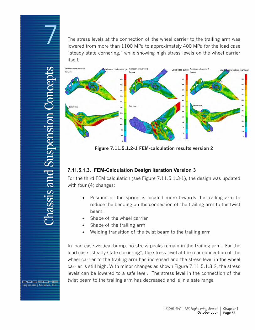
The stress levels at the connection of the wheel carrier to the trailing arm was
lowered from more than 1100 MPa to approximately 400 MPa for the load case
“steady state cornering,” while showing high stress levels on the wheel carrier
itself.
Figure 7.11.5.1.2-1 FEM-calculation results version 2
7.11.5.1.3. FEM-Calculation Design Iteration Version 3For the third FEM-calculation (see Figure 7.11.5.1.3-1), the design was updated
with four (4) changes:
• Position of the spring is located more towards the trailing arm to
reduce the bending on the connection of the trailing arm to the twist
beam.
• Shape of the wheel carrier
• Shape of the trailing arm
• Welding transition of the twist beam to the trailing arm
In load case vertical bump, no stress peaks remain in the trailing arm. For the
load case “steady state cornering”, the stress level at the rear connection of the
wheel carrier to the trailing arm has increased and the stress level in the wheel
carrier is still high. With minor changes as shown Figure 7.11.5.1.3-2, the stress
levels can be lowered to a safe level. The stress level in the connection of the
twist beam to the trailing arm has decreased and is in a safe range.

Engineering Services, Inc..
7Ch
assi
s an
d Su
spen
sion
Con
cept
s
ULSAB-AVC – PES Engineering Report June 2001
Chapter 7Page 57
Figure 7.11.5.1.3-1 FEM-calculation results version 3
Figure 7.11.5.1.3-2 Modifications of the wheel carrier
To assess the manufacturing feasibility of the trailing arm, ULSAB-AVC Con-
sortium Member Company conducted a forming simulation for the tubular trail-
ing arm, analyzing each manufacturing step. The forming simulation results
showed that design optimization of the trailing arm would need to be done in a
detail design phase.

Engineering Services, Inc..
7Ch
assi
s an
d Su
spen
sion
Con
cept
s
ULSAB-AVC – PES Engineering Report June 2001
Chapter 7Page 58
7.11.6. Twist Beam ProleThe material used for the twist beam profile is MnB 1200/1600 in a material
thickness of 2.5 mm. The flat material properties in delivery condition (before
heat treatment) are 280/450.
The twist beam profile (see Figure 7.11.6-1) has a complicated shape. Similar
shapes are used in existing high volume production twist beam production rear
suspensions. The main distinction is that the torsion profile for the ULSAB-AVC
rear suspension is flared at the outer ends of the welded seam to the trailing
arms. With this measure, the length of the welding seam is increased and the
support base for side forces is enlarged with the effect that the toe out behavior
of the rear suspension is minimized.
The parts manufacturing is performed in a 2-stage process. The first stage is a
deep drawing of the tube to obtain the spring rate of the desired torsion bar. In
the subsequent hydroforming process (second stage), the ends of the tube are
widened. Axial force-feeding is used to achieve a nearly constant wall thickness
at the widened tube ends.
After the forming process, the twist beam must be heat treated to achieve the
required strength.
Figure 7.11.6-1 Twist beam profile

Engineering Services, Inc..
7Ch
assi
s an
d Su
spen
sion
Con
cept
s
ULSAB-AVC – PES Engineering Report June 2001
Chapter 7Page 59
7.11.7. Wheel Bearing and HubsThe wheel bearing as shown in Figure 7.11.7-1 encompasses a double row annu-
lar ball bearing with the following dimensions:
Outer diameter 72 mm
Inner diameter 36 mm
Width 39 mm
Figure 7.11.7-1 Wheel bearing and hub
The bearing has a multiple sealing with lifetime greasing. A very important point
for durability of these parts is their temperature resistance, which has an influ-
ence to the sealing of the wheel bearing, as well as to the dimensional stability
of the hub, because of the potential problems caused by the brake system, such
as squeezing and wobbling.
For mass reduction, the shape of the surface for the wheel attachment has been
reduced to a minimum and has to be confirmed or optimized (adjusted) in con-
junction with tests of the rear suspension in regards to camber stiffness.

Engineering Services, Inc..
7Ch
assi
s an
d Su
spen
sion
Con
cept
s
ULSAB-AVC – PES Engineering Report June 2001
Chapter 7Page 60
7.11.8. Shock Absorber Rear SuspensionFor each C-Class and PNGV-Class vehicle, with either diesel or gasoline engine,
a different damper with a special characteristic is needed and is designed as
a single-tube shock absorber with an integrated bump stop for limiting wheel
movement. (see Figure 7.11.8-1).
Figure 7.11.8-1 Shock absorber rear suspension
The shock absorber is bolted to the body structure and to the trailing arm
through rubber bushings at its upper and lower mounting points. The wall thick-
ness of the shock absorber tube is minimized and a plastic coating is applied
to protect the tube against damages caused by stone chipping. For mass reduc-
tion, the piston rod is designed as a hollow component. The shock absorber
must function in a temperature range from 40°C to 160°C.
Engineering Services, Inc..
7Ch
assi
s an
d Su
spen
sion
Con
cept
s
ULSAB-AVC – PES Engineering Report June 2001
Chapter 7Page 61
7.12. Brake System
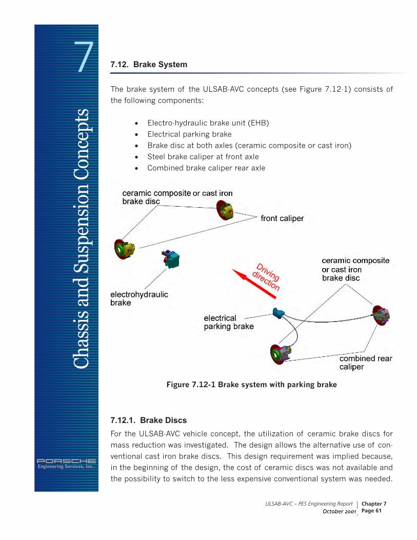
The brake system of the ULSAB-AVC concepts (see Figure 7.12-1) consists of
the following components:
• Electro-hydraulic brake unit (EHB)
• Electrical parking brake
• Brake disc at both axles (ceramic composite or cast iron)
• Steel brake caliper at front axle
• Combined brake caliper rear axle
Figure 7.12-1 Brake system with parking brake
7.12.1. Brake DiscsFor the ULSAB-AVC vehicle concept, the utilization of ceramic brake discs for
mass reduction was investigated. The design allows the alternative use of con-
ventional cast iron brake discs. This design requirement was implied because,
in the beginning of the design, the cost of ceramic discs was not available and
the possibility to switch to the less expensive conventional system was needed.

Engineering Services, Inc..
7Ch
assi
s an
d Su
spen
sion
Con
cept
s
ULSAB-AVC – PES Engineering Report June 2001
Chapter 7Page 62
The parts cost assessment showed that the costs for ceramic brake discs would
drive the vehicle manufacturing and assembly cost, therefore it was decided to
utilize conventional cast iron brake discs.
7.12.2. Brake CalipersThe brake calipers used for ULSAB-AVC are carry-over parts from vehicles cur-
rently in production. The dimensions are typical for vehicles with similar mass
and performance.
At the front axle, compared with similar vehicles, about two-third of the brake
performance is applied. For the concept, a sliding one-piston caliper made of
forged steel was used for stiffness and braking sensibility reasons. Brake pads
as well as the accessory parts such as pins and springs are also carry-over parts
from other vehicles.
The brake performance at the rear axle of a front drive vehicle with front-
mounted engine is much lower than at the front axle. The caliper of the rear
axle is a sliding one-piston caliper combined with a parking brake. The lower
stiffness of the rear caliper does not affect the brake sensibility, due to the lower
force level. The accessory parts used are carry-over parts from other vehicles
and the same as used for the front axle.
For the front and rear brakes, a good acoustic and comfort behavior of the
system is essential. Squeaking noise and juddering is not acceptable. Therefore,
very complex vibration calculations and prototype testing would be necessary in
a detail design phase.
7.12.3. Electro-Hydraulic Brake (EHB)The electro-hydraulic brake unit (EHB) includes an electrical pump, a reservoir,
valve block, pedal force simulator and control unit. The EHB unit is a carry-over
part from a Tier One Supplier. The adaptation of the system to different vehicles
is achieved by modifying the software of the control unit. To avoid too many
different variations of hardware and software for the vehicle variants, different
software solutions must be stored on the control unit.

Engineering Services, Inc..
7Ch
assi
s an
d Su
spen
sion
Con
cept
s
ULSAB-AVC – PES Engineering Report June 2001
Chapter 7Page 63
7.12.4. Electrical Parking BrakeThe electrical parking brake system as shown in Figure 7.12.4-1 includes an
electrical actuator and two (2) bowden cables. The actuator is attached to the
body structure. The advantage of the electrical parking brake system is that the
bowden cables from the rear axle to the hand brake lever in the cockpit as well
as the hand brake lever itself are eliminated. The actuator is controlled from
a switch in the cockpit and connected with a wire. Other advantages are in the
final assembly, where no bowden cables have to be routed through the body
structure.
Figure 7.12.4-1 Electrical parking brake system
7.13. Wheels and Tires
The wheels selected for the ULSAB-AVC vehicles are made of steel, utilizing
High Strength Steels (HSS) and tailor welded blanks. More information can be
obtained in the ULSAB-AVC Wheel Technology Report.
The wheel size is 5J x 14 and the tire size selected is 175/65 R14.
Engineering Services, Inc..
7Ch
assi
s an
d Su
spen
sion
Con
cept
s
ULSAB-AVC – PES Engineering Report June 2001
Chapter 7Page 64
7.14. Parts/Mass Lists and Drawings
For a detailed part/mass/material specification lists and part drawings – see
Appendix - Section 7.1.
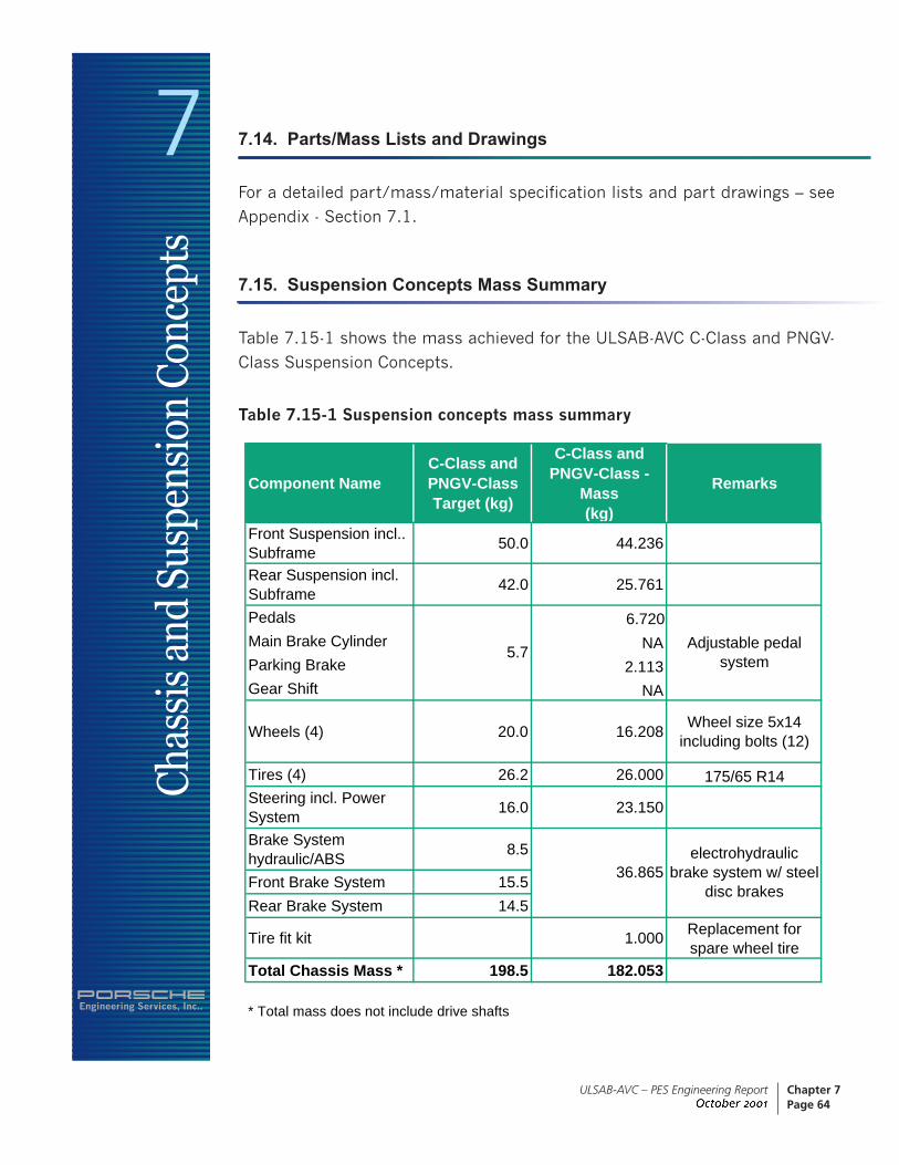
7.15. Suspension Concepts Mass Summary
Table 7.15-1 shows the mass achieved for the ULSAB-AVC C-Class and PNGV-
Class Suspension Concepts.
Table 7.15-1 Suspension concepts mass summary
Component NameC-Class and PNGV-Class Target (kg)
C-Class and PNGV-Class -
Mass (kg)
Remarks
Front Suspension incl.. Subframe 50.0 44.236
Rear Suspension incl. Subframe 42.0 25.761
Pedals 6.720Main Brake Cylinder NAParking Brake 2.113Gear Shift NA
Wheels (4) 20.0 16.208 Wheel size 5x14 including bolts (12)
Tires (4) 26.2 26.000 175/65 R14Steering incl. Power System 16.0 23.150
Brake System hydraulic/ABS 8.5
Front Brake System 15.5Rear Brake System 14.5
Tire fit kit 1.000 Replacement for spare wheel tire
Total Chassis Mass * 198.5 182.053
* Total mass does not include drive shafts
36.865electrohydraulic
brake system w/ steel disc brakes
Adjustable pedal system5.7

Engineering Services, Inc..
7Ch
assi
s an
d Su
spen
sion
Con
cept
s
ULSAB-AVC – PES Engineering Report June 2001
Chapter 7Page 65
7.16. Vehicle Load Distribution
The vehicle load distribution relative to front and rear suspension at vehicle curb
mass is shown in Table 7.16-1.
Table 7.16-1 Front/Rear axle distribution
Front/Rear Axle Distribution Front Suspension (%)
Rear Suspension (%)
Curb Mass (kg)
C-Class Gasoline 55 45 935
C-Class Diesel 56 44 965
PNGV-Class Gasoline 54 46 1000
PNGV-Class Diesel 55 45 1030
7.17. Summary
The ULSAB-AVC suspension concepts show the target has been surpassed using
steel as the material of choice. In combination with a range of high strength
steels, new technologies such as tailor welded blanks for wishbones and tailor
tube hydroforming were implemented.
Suspension components such as lightweight steel wheels, electrical parking
brake, electro-hydraulic brake system, tailor welded blanks and wishbones uti-
lizing high strength steel have contributed to surpass the mass reduction target.
However, further mass reduction is possible with the utilization of ceramic brake
discs.
The front end module concept could be implemented into the front suspension
design, thus providing the desired advantages in final assembly.