7 a-ai16 730 construction engineering …english language, command-oriented system capable of...
TRANSCRIPT
7 A-AI16 730 CONSTRUCTION ENGINEERING RESEARCH LAB (ARRY) CHAMPAI6N IL F/e 5/1MX RESIDENT ENGINEER NETWORKING GUIDE. CU)APR 82 M J O'CONNOR. B E COLWELL IAO-E$7-81-7151
UN7CLASSIFIED CERLTRPIZA NL

________ON /MM MEMMI
construction United Stntes Army>Corps of Engineers TCNCLRPR -2engineering e teAyTCNCLRPTP12
SMn ng th0 Notion April, 1982Sresearchc laboratory_____
MX RESIDENT ENGINEER NETWORKING GUIDE
byM. J. O'Connor
G. E. ColwellR. D. Reynolds
Approved for public release distribution unlimited.
82 07 09 002

The contents of this report are not to be used for advertising, publication, ofpromotional purposes. Citation of trade names does not constitute anofficial indorsement or approval of the use of such commercial products.The findings of this report are not to be construed as an official Departmentof the Army position, unless so designated by other authorized documents.
DESTROY THIS REPORT WHEN ITIS NO I ONGER NEEDED
DO NOT RETURN IT TO THE ORIGIN.4 TOR
,+-.1 + --- I

UNCLAS S IFIED
SECURITY CLASSIFICATION OF THIS PAGE (1When Del. Entered)REPOT DCUMHTATON AGEREAD INSTRUCTIONS
REPOT DCUMNTATON AGEBEFORE COMPLETING FORM
I. REPORT NUMBER 2. GOVT ACCESSION NO. 3. RECIPIENT'S CATALOG NUMBER
CERL-TR-P- 126.,- / "
4. TITLE (and Subtitle) S. TYPE OF REPORT & PERIOD COVERED
MX RESIDENT ENGINEER NETWORKING GUIDE FINAL
6. PERFORMING ORG. REPORT NUMBER
7. AUTHOR(e) 8. CONTRACT OR GRANT NUMBER(m)
M. J. O'CONNORG. E. COLWELLR. D. REYNOLDS
9. PERFORMING ORGANIZATION NAME AND ADDRESS 10. PROGRAM ELEMENT. PROJECT, TASKU.S. ARMY AREA & WORK UNIT NUMBERS
CONSTRUCTION ENGINEERING RESEARCH LABORATORYP.O. BOX 4005, Champaign, IL 61820
11. CONTROLLING OFFICE NAME AND ADDRESS 12. REPORT DATE
April 198213. NUMBER OF PAGES
14014. MONITORING AGENCY NAME & ADDRESS(If different from Controlling Office) IS. SECURITY CLASS. (of this report)
Unclassified
15. DECL ASSI FICATION/DOWNGRADINGSCHEDULE
16. DISTRIBUTION STATEMENT (of this Report)
Approved for public release; distribution unlimited.
17. DISTRIBUTION STATEMENT (of the ebetrect entered In Block 20, If different from Report)
1S. SUPPLEMENTARY NOTES
Copies are obtainable from the National Technical Information ServiceSpringfield, VA 22151
19. KEY WORDS (Continue on reveres side If necessary and Identify by block number)
MX missilesManagement information systemsNetwork analysis (management)MX Construction Management System
Ilk ATrRAC" (Clm d,. .- everee e a fnegee , . &d ideriify by block n.-.bet)
This report instructs Resident Engineers with MX project responsibilitieson the use of the MX Construction Management System, an automated NetworkAnalysis System (HAS) developed by the U.S. Army Construction EngineeringResearch Laboratory (CERL).
DO ,IMMP 1473 1MIowOF 1 OVSSISONSOLETE UNCLASSIFIED
SECUI"TY CLASSIFICATION OF THIS PAGE (ien Daot Entered)

FOREWORD
This investigation was performed for the U.S. Army Corps of Engineers,Management Support Office, Corps of Engineers MX Program Agency (CEMXPA),under IAO No. E87-81-7151, "Integrated Hierarchical Networks for MX." TheCEMXPA Technical Monitor was Mr. Richard Fraser.
The work was performed by the Facility Systems (FS) Division of the U.S.Army Construction Engineering Research Laboratory (CERL). Mr. E. A. Lotz isChief of CERL-FS.
COL Louis J. Circeo is Commander and Director of CERL, and Dr. L. R.Shaffer is Technical Director.
3

CONTENTS
Page
DD FORM 1473 1FOREWORD 3LIST OF TABLES AND FIGURES 6
INTRODUCTION ............................................................ 11BackgroundApproachPurposeScope
2 SYSTEM OVERVIEW ....................................................... 13System ModulesTerminal OperationPrinter OperationModemLOGON and LOGOFF ProcedureMenu Selection
3 ORIGINAL SUBMITTAL ................................................... 21InputAnalysisNAS General Requirement ChecklistPlanning Revisions
4 PROGRESS REPORTING AND PAYMENT ESTIMATES ............................... 31Progress ReportingPayment EstimatesSecurityAuthenticating PasswordsOperational PasswordsElectronic TransferRecord Copies
5 MODIFICATIONS AND CLAIMS .............................................. 46Change OrdersImpact AnalysisRequest for Proposal (RFP)FinalizationNetwork RevisionsClaims
6 SUPPLEMENTAL MODULES........... ....................................... 52User Message ModulePROJECT/2 AccessOffice Support Module
7 CONCLUSION ........................................................... 56
4

APPENDIX A: MX Construction Management System Module Screens 57APPENDIX B: Example Special Provision 133APPENDIX C: Notice to Contractor (Use of ENG Form 3938) 139
DISTRIBUTION
5
5

TABLES
Number Page
I Checklist for NAS General Requirements 23
FIGURES
1 Schematic Overview 12
2 Major System Modules 13
3 Terminal and Keyboard 16
4 Model Controls and Indicators 17
5 Rear View of Terminal and Modem Configuration 18
6 LOGON Procedure 19
7 Screen 1 -- Message Notice and Module Selection 20
8 Flowchart -- Module 11 21
9 Module 13 -- Flowchart 22
10 Coding for MX Construction 26
11 Module 14 -- Flowchart 32
12 Sample Update Input Report 33
13 Module 16 -- Flowchart 35
14 Sample Planning Schedule Report 36
15 Sample Payment Estimates Report 37
16 Sample Working Schedule Report 39
17 The Payments Statement Report 41
18 The Summary Payments Statement Report 42
19 The Payment Estimates Report -- Sample 1 43
20 The Payment Estimate Report -- Sample 2 44
21 Module 15 -- Flowchart 47
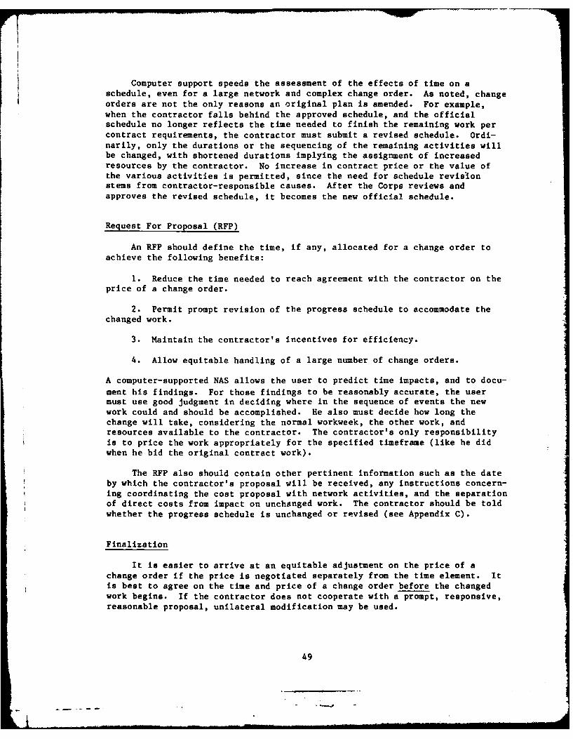
22 Flowchart -- Module 18 53
6

FIGURES (Cont'd)
Number Page
23 PROJECT/2 Flowcharrt 53
24 Module 19 -- Flowchart 54
Al Module 11 -- Screen 11 58
A2 Module 11 -- Screen Ill 59
A3 Module 11-- 1111 60
A4 Module 11 -- Screen 1112 61
A5 Module 11 -- Screen 1113 62 IA6 Module 11 -- Screen 1114 63
A7 Module 11 -- Screen 1115 64
A8 Module 11 -- Screen 1116 65
A9 Module 11 -- Screen 1117 66
AIO Module 11 -- Screen 1118 67
All Module 11 -- Screen 112 68
A12 Module 11 -- Screen 113 69
A13 Module 11 -- Screen 114 70
A14 Module 13 -- Screen 13 71
A15 Module 13 -- Screen 131 72
A16 Module 13 -- Screen 132 73
A17 Module 13 -- Screen 133 74
A18 Module 14 -- Screen 14 75
A19 Module 14 -- Screen 141 76
A20 Module 14 -- Screen 142 77
A21 Module 14 -- Screen 1421 78
A22 Module 14 -- Screen 1422 79
A23 Module 14 -- Screen 143 80
7
"' -- -- I] III- . . . . . . .

FIGURES (Cont'd)
Number Page
A24 Module 14 -- Screen 1431 81
A25 Module 14 -- Screen 1432 82
A26 Module 14 -- Screen 144 83
A27 Module 16 -- Screen 16 84
A28 Module 16 -- Screen 161 85
A29 Module 16 -- Screen 162 86
A30 Module 16 -- Screen 1621 87
A31 Module 16 -- Screen 1622 88
A32 Module 16 -- Screen 1623 89
A33 Module 16 -- Screen 1624 90
A34 Module 16 -- Screen 1625 91
A35 Module 16 -- Screen 1626 92
A36 Module 16 -- Screen 1627 93
A37 Module 16 -- Screen 163 94
A38 Module 16 -- Screen 164 95
A39 Module 16 -- Screen 165 96
A40 Module 16 -- Screen 166 97
A41 Module 15 -- Screen 15 98
A42 Module 15 -- Screen 151 99
A43 Module 15 -- Screen 152 100
A44 Module 15 -- Screen 1521 101
A45 Module 15 -- Screen 1522 102
A46 Module 15 Screen 1523 103
A47 Module 15 -- Screen 1524 104
A48 Module 15 -- Screen 1525 105
8A48 Modle - Sceen152 405
- 4

FIGURES (Cont'd)
Number Page
A49 Module 15 -- Screen 1526 106
A50 Module 15 -- Screen 153 107
A51 Module 15 -- Screen 154 108
A52 Module 15 -- Screen 155 109
A53 Module 15 -- Screen 156 110
A54 Module 12 -- Screen 12 il1
A55 Module 12 -- Screen 121 112
A56 Module 12 -- Screen 122 113
A57 Module 12 -- Screen 123 114
A58 Module 12 -- Screen 1231 115
A59 Module 12 -- Screen 1232 116
A60 Module 12 -- Screen 1233 117
A61 Module 12 -- Screen 1234 118
A62 Module 12 -- Screen 1235 119
A63 Module 12 -- Screen 1236 120
A64 Module 12 -- Screen 1237 121
A65 Module 12 -- Screen 124 122
A66 Module 12 -- Screen 125 123
A67 Module 18 -- Screen 18 124
A68 Module 18 -- Screen 181 125
A69 Module 18 -- Screen 182 126
A70 Module 18 -Screen 183 127
A71 Module 18 -- Screen 1831 128
A72 Module 18-- Screen 184 129
A73 Module 18 -- Screen 185 130
9

FIGURES (Cont'd)
Number Page
A74 Module 17 Screen 131
132
A75 Module 19 Screen
10

MX RESIDENT ENGINEERNETWORKING GUIDE
1 INTRODUCTION
Background
The Network Analysis System (NAS) is not a new planning method. It hasbeen used for more than 20 years to record or graphically portray conventionalplanning. NAS demands much greater detail than such procedures as Ghant orbar charts. NAS displays the logic or order and interdependence of variousactivities so they can be analyzed, recalled, and applied to any eventualityas the project progresses. NAS considers planning as well as the timerequired to perform each task, the cost or value of the activities, themathematical computations relevant to the system, and the evaluation of theresults. Many variations of the basic NAS, designed to suit specific userneeds, are available. Of these variations, the Critical Path Method (CPM) hasbeen specified by the U.S. Army Corps of Engineers as best suited to theCorps' construction needs.
The Corps' past experience with NAS and CPM schedules has not lived up toexpectations. This is probably because the CPM schedules used by the Corpsdepend on the construction contractor for computer support. Things happenrapidly on a construction project, so there must be a quick means of analyzingchanging situations, and adjusting the plan accordingly. Without inhouse com-puter support at the field-office level, the Corps is at a disadvantage. Alltoo often, the original progress schedule becomes outdated early in the joband stays that way. As a result, it is very difficult to evaluate the impactof change orders so their settlement is delayed; the incentives for the con-tractor to effectively manage the job deteriorate; and the Corps loses theability to direct or even effectively influence positive action.
The question of computer support is critical given the Corps' responsi-bility for managing the huge MX program. It is generally recognized thatNAS/CPM is the best construction management tool; it is imperative that it beused on the MX work and that the Corps obtain the computer capability to makeit work successfully.
The development of solutions to the problem of providing necessary com-puter capability to Corps field personnel in an easy-to-use form was assignedto the U.S. Army Construction Engineering Research Laboratory (CERL) in March1981. This report documents the results of one aspect of that total effort.
Approach
The automation of the project planning process began in the late 1950sand early 1960s when CPM scheduling was established as a valuable planningtool. The project planner identifies the project activities and their inter-dependencies. This information can be shown graphically on a network diagram.Once the network logic has been defined, the time and resources required to
11

perform each activity can be estimated. The use of computers for project
scheduling and cost control has expanded the original network scheduling tech-niques and permits planners to control increasingly more complicated applica-tions.
Introduced by Project Software & Development, Inc. in 1968, PROJECT/2 was
one of the first systems that used sophisticated computer techniques to handlethe requirements posed by large-scale projects. The system uses CPH tech-niques to monitor and control schedules, and an earned value approach to moni-tor and control costs. Although cost and schedule processing can beintegrated, PROJECT/2 allows the user complete flexibility in determining howmuch of the software is necessary for each application. PROJECT/2 is anEnglish language, command-oriented system capable of operating in a totallyinteractive machine mode.
CERL determined that PROJECT/2 meets the Corps' MX networking needsbetter than anything else currently available. To use the capabilities ofPROJECT/2 without requiring users to learn PROJECT/2 command language, CERLdeveloped the MX Construction Planning Management System.
The main element of the MX Construction Planning Management System is the
menu system. This is a software package designed to facilitate the user'sinteraction with PROJECT/2 in familiar contract administration terms. FigureI shows the relationship between the user, the menu system, PROJECT/2, andother elements of the integrated planning and control system.
Purpose
The purpose of this report is to describe the MX Construction Planning
Management System, a computer-aided management and information system, and toprovide field offices with guidance for its use.
Scope
The information in this report is intended for Resident/Area Engineershaving MX contract administration responsibilities.
Figure I. Schematic overview.
12
USER MEN COMPUTER
SYSTEM . STORiI I .. .. . . . . .... .l AGE. . .... . . .

I
2 SYSTEM OVERVIEW
The MX Construction Planning Management System is designed for users withlittle or no computer experience, although a working knowledge of network-based management is expected since most system aspects are related, in someway, to a project network. The system is interactive, prompting users atevery step, from system entry to exit. It links all major aspects of con-struction planning, then monitors progress and payments to contractors in sup-port of the Government's construction management functions. The system wasspecifically tailored to make it easy to use while providing all the necessaryfunctions; additional options are available through PROJECT/2 for those usersfamiliar with PROJECT/2 command language.
System Modules
Figure 2 shows the major system modules: Jo Module 1: The System Access and Control Module performs front-end
system control. It ensures that all aspects of the system procedure are func-tioning, and monitors user input. User interaction with Module 1 is limitedto LOGON, LOGOFF, and password input.
SYSTEMENTRYCONTROLMODULE
INPUT ANALYZE MODIFICATION FULL OFFICENEW NEW NETWORK IMPACT IPROJECT/2 SUPPORTNETWORK SUBMITTAL EVALUATION ACCESS MODULEMODULE MODULE 13 MODULE 15 MODULE
CORRECT/ PROGRESS REPORTS USERREVISE REPORTING/ MODULE MESSAGESTORED NET PAYMENT MODULEMODULE 12 MODULE 14 16 18
Figure 2. Major system modules.
13
.. . . , i ,n f . . . I . . " - ~

o Module 11: The Input New Network Module has a number of options whichlet the user (1) create and edit an input file for PROJECT/2, (2) add a net-work to PROJECT/2, and (3) output a logical series of analysis reports (afterthe network is loaded). A network is only added via the STORE NEW NETWORKoption. Thus, the user may build and then change an input file until a net-work is successfully loaded into PROJECT/2.
o Module 12: The Correct/Revise Stored Network Module is used to changea stored network. A network would change when errors are discovered in thenew network input, changes are made to the contractor's work plan andsequence, the contract is modified, etc. Module 12 is the only module whichcan permanently change a stored network.
o Module 13: The Analyze New Network Submittal Module produces reportsused to evaluate a new network submittal. After a new network is analyzed andapproved, Module 13 releases it to the official file.
o Module 14: The Progress Reporting/Payment Request Module logicallycombines the functions needed to develop a payment request, including thedevelopment of actual progress, analysis of cost data, preparation of requiredforms, and tracking of payment actions.
o Module 15: The Modification Impact Evaluation Module lets the userpredict the results of a number of "what if" scenarios to help determine theleast disruptive and/or costly way to handle contract change orders. Module15 also can evaluate the merit of claims. Module 15 cannot change the offi-cial file -- it is used only to develop change order options, which can thenbe implemented (placed in official file) using Module 12.
o Module 16: The Reports Module lets the user output PROJECT/2 reports,in a variety of customized formats, without having to know PROJECT/2 language.This module supplements the standard reports available through other modules.Information may be obtained in hard copy or on the screen.
o Module 17: The Full PROJECT/2 Access Module lets certain users accessfull PROJECT/2 operations; users must know PROJECT/2 job control language touse Module 17.
o Module 18: The User Message Module lets users communicate with oneanother. The message originator specifies which users are to receive a mes-sage; users are given messages when they logon to the system. Each user hasan individual message set for holding messages from other system users. Eachuser can review or remove messages from his* message set at any time. How-ever, the system will automatically delete any messages more than 15 days old.
o Module 19: The Office Support Module has a number of submodules tohelp the field office prepare correspondence, do cost estimates, keep pay-rolls, track various functions, ascertain latest policies and procedures,access information sources, etc. These submodules relieve the field officefrom time-consuming, nonengineering duties, so it can devote its attention toquality assurance and contract administration.
* The male pronoun is used throughout this report to refer to both genders.
14

Terminal Operation
System terminals are used to type in input data and obtain report prin-touts (Figure 3). The terminal's keys are the same as those on a standardtypewriter or calculator. Special key functions are listed below.
The CURSOR is a blinking square on the terminal screen which indicatesthe user's position in the input sequence; the CURSOR prompts the user forinformation, as needed.
The RETURN key signals the system that an entry is complete. The usershould tap the RETURN key after he finishes inputting a data sequence. Whenthe user taps the RETURN key, the CURSOR will move to the next entry in thesequence; tapping the RETURN key in front of a blank entry will also promptthe CURSOR onto the next entry.
The BACKSPACE key lets the user correct an incorrect entry only if theRETURN key has not yet been struck. Tapping the BACKSPACE key will move theCURSOR one space from right to left; the user may then type over the incorrectentry. If the RETURN key has already been struck, the user must make theinput correction using the system's EDIT/REVIEW mode.
Printer Operation
To print out screen information, the user depresses the SHIFT key andsimultaneously strikes the PRINT key (see Figure 4). The terminal will notsend information to the computer while the printer is in operation.
Modem
Figure 4 shows the Racal-Vadic modem controls and indicators. Twoswitches are on the front of the modem: FA and HS. Both should lean towardthe back of the modem. The rear of the modem also has two switches; bothshould be turned to the left and set at DLB/IRT and NORMAL. The user will notchange the position of the modem switches during normal system operation.
Figure 5 shows a rear view of the terminal and a typical modem hook-up
configuration.
LOGON and LOGOFF Procedure
The user begins and ends terminal operation using the LOGON and LOGOFF
commands.
After making the proper telephone-modem connection to the computer ser-
vice system, the terminal will ask the user a series of questions before
15

n
CURSOR-
*~~ 00 0000 IZ D
Figure 3. Terminal and keyboard.
16
B I-Fi ! 1 ITIM m -. l --II.lil I1I]r1

-SPEED ($: HIGH, 4LOW)-FORCE ANSWER (4)
FRONT VIEW
-DLB/IRT NRAOF FALB- ~ SELF TEST
LDTE CONNECTOR
REAR VIEW
Figure 4. Modem controls and indicators.
17

* • SERIAL PRINTERS: -- CONNECTOR
INDICATOR
ACCESSCOVER
Jill 111 EIA COMMUNICAT IONSCONNECTOR
EXTERNAL VIDEOINPUT CONNECTOREXTERNAL VIDEOOUTPUT CONNECTOR
MODEM MAIN FUSECONNECTION - POWER SWITCH
MODEL + SERIALKEYBOARD NUMBER LABEL
CONNECTOR 0 0
POWER CORDOPTIONAL 2OmA POWER CONNECTORCOMMUNICATION SELECTORCONNECTOR SWITCH
VA871DATA JACK RACAL-VADICRJ45S OR RJ41S ACCESSORYOR RJIIC(TELCO SUPPLIED)
* TERMINALPOWER CONNECTION
Figure 5. Rear view of terminal and modem configuration.
18

allowing the user access to the MX Construction Planning Management System(see Figure 6):
1. The system asks: SELECT DESIRED SERVICE
2. The user enters: TSO (hit RETURN key)
3. The system shows: MAINSTREAM-TSO
4. The user enters: LOGON CHP n n n/(password) NON (hit RETURN key)
(Note: n n n is a three-digit ID number for the user;
a password will be given by the system manager)
5. The system asks: ENTER PROCEDURE NAME
6. The user enters: CEMX (hit RETURN key)
The user may exit (LOGOFF) the system by selecting the EXIT SYSTEM optionand striking the RETURN key. This option is available on many screens stra-tegically phased throughout the system.
MX CONSTRUCTION MANAGEMENT SYSTEM
Welcome to the bcs networkYour access port is scy 072
Select desired service: tso
MAINSTREAM-TSOlogon chpOOI/xxxxx nonENTER PROCEDURE NAME -
cemxCHPOO LOGON IN PROGRESS AT 13:05:29 ON JULY 10, 1981NO BROADCAST MESSAGESNO "ACTIVE" DATA SETS
Figure 6. LOGON procedure.
19

Menu Selection
After the user successfully completes the LOGON procedure, Screen 1, theMessage Notice and Module Selection will appear (Figure 7). At this time, theuser will be shown any message entered into the system. Options 1 through 9allow the user to enter any system module, assuming the user has the propersecurity classification. Option 10 will effect a LOGOFF.
Options 1 through 9 directly correspond to Modules 11 through 19.
MX CONSTRUCTION MANAGEMENT SYSTEMSYSTEM ENTRY AND CONTROL MODULE
(Message notices will appear here)
System options:
1. Input new network2. Correct/revise stored network3. Analyze new network submittal4. Report progress/payment5. Evaluate modification impact6. Produce reports7. Use full PROJECT 28. Send messages9. Office support module10. Exit system
Enter option or help:
Figure 7. Screen I -- Message Notice and Module Selection.
20

3 ORIGINAL SUBMITTAL
This chapter describes how Modules 11 and 13 are used to input, analyze,and evaluate a contractor's original submittal data. (Module screens arepresented in Appendix A.)
Input
The contractor's construction schedule responsibilities are defined inthe contract's General and Special Provisions. Appendix B is an example Spe-cial Provision compatible with the MX Construction Planning Management System.The contractor's network submittal should be formatted so it can be electroni-cally copied into the Government's automated data processing (ADP) files; theSpecial Provision should require this for the original submittal. Later, how-ever, the contractor may wish to change only a few pieces of network data;this can be done manually. The Resident Engineer also may wish to manuallyinput a network for his own use. Consequently, Module 11, the Input a NewNetwork module, allows both manual and automatic input of network data. Fig-ure 8 is a Module 11 flowchart. The screens supporting Module 11 are shown inAppendix A, Figures Al through A13.
Module 11 inputs the network to PROJECT/2, where it may be processed andstored.
SINPUT
NEWNET WORKMODULE
DESCRIPTIVE NEW N4ETWORK I ERROR CHECK I AINOMTO NU NEW NETWORK NETWORK
FN I U 112 113- 114
OUTPUT
E ENTER
GLOBALDESCRIPTIONS= IPT I I ,O / "'-
NETWO K REATN SHIPS - CONSTRA'NTSJDATARLAIN IP _I (A/N) WNl
(A/N) 111411$HIl
INPUOIN1G0DATA Ill ATNETWORKA/)N T I5 CONSTRAINTS(AAAlN Ijl
Figure 8. Module 11 -- flowchart.
21

Analysis
Module 13, Analyze New Network Submittal, allows the user to print outreports he can use to evaluate the contractor's work plan. A Module 13flowchart is shown in Figure 9. The screens supporting Module 13 are shown inAppendix A, Figures A14 through A17. In the event Module 13's standardreports do not entirely fulfill the users' needs, other reports are availablefrom Module 16 or Module 17.
Module 13 lets the user release the approved schedule to the officialfile. In the official file, data are available to others in the organiza-tional structure served by the system. All other files are working files,accessible only to those who created them.
NAS General Requirement Checklist
The checklist in Table 1 can be used to systematically analyze acontractor's initial network submittal. The checklist is arranged so eachitem references a system module that can provide the information needed toanswer the question. Since some computer aids answer more than one question,there is some duplication; however, when performing a complete analysis,duplicate copies of a particular report are not needed. To intelligentlyjudge the validity of a contractor's proposed schedule, the user must know thescope and details of the work and the requirements affecting it.
ANALYZENEW NETWORKSUBMITTALMODULE
~RELEASELIST SELECT TOACTIVE REPORTS
NEWRS1311 132 FILE 133
r---OUTPUT
Figure 9. Module 13 -- flowchart.
22
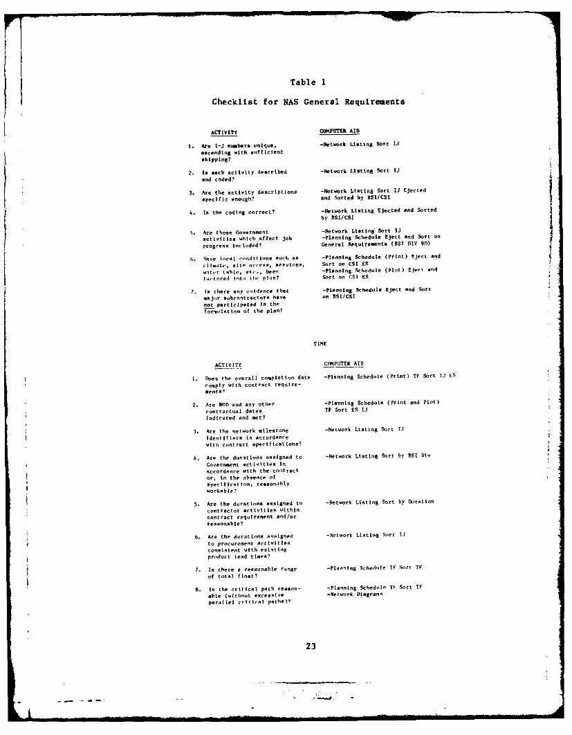
Table 1
Checklist for NAS General Requirements
ACTIVITY COMPUTER AID
1. Are I-J numbers unique. -Network Listing Sort IJ
ascending with sufficientskipping?
2. Is each activity described -Network Listing Sort IJ
and coded?
3. Are the activity descriptions -Network Listing Sort IJ Ejectedspecific enough? and Sorted by BSI/CSI
4. Is the coding correct? -Network Listing Ejected and Sorted
by BSI/CSI
5. Are those Government -Network Listing Sort IJ
activities which affect job -Planning Schedule Eject and Sort on
progress Included? General Requirements (BSI DIV 90)
6. Nave local conditions such as -Planning Schedule (print) Eject and
ciimcAt', site ac'se. servlces, Sort on CSI ES
water table, etc., been -Planning Schedule (Plot) Eject And
fnctored into thu plin? Sort on CSI ES
7. In there any evidence that -Planning Schedule Elect and Sort
majr subcontractors have on 8SI/CSInot participated in the
formulation of the plan?
TIME
ACTIVITY COMPUTER AID
I. Does the overall completion date -Planning Schedule (Print) TF Sort IJ ES
comply with contract require-ments?
2. Are BOD and any other -Planning Schedule (Print and Plot)contractual dates TF Sort ES IJ
indicated and met?
3. Are the network milestone -Network Listing Sort iJ
Identifiers in accordancewith contract specifications?
4. Are the durations assigned to -Network Listing Sort by 5SI Div
Government activities inaccordance with the contract
or, in the absence ofspecification. ressonalbyworkable?
5. Are the durations assigned to -Network Listing Sort by Duration
contractor activities withincontract requirement and/orreasonable?
6. Are the durations Assigned -Network Listing Sort 1.1
to procurement activitiesconsistent with exsintlgproduct lead times?
7. Is there a reasonable range -Planning Schedule TF Sort TV
of total float?
a. is the critical path reason- -Planning Schedle TF Sort TF
able (without excessive -Network Diagrams
paraliel critical paths)?
23
a. - -.....
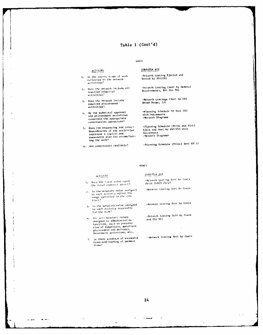
Table 1 (Cont'd)
LOGI C
ACTIVITYCOMPUTER AID
I. Is tile entire S-ope of work -Network Listing Ejected and
rei tected in tile network Sorted by BSVCS1
activitiles?
W.Des the network include all -Network Listing (Sort by General
required submittal Requirements, BSI Div 90)
activities?
3. Does the network inclucle -Network Listings (Sort by CSI
required procurement Broad Scope, IJ)
activities?t
4. Do the Submittal approval -Planning Schedule TF Sort CSI
and procurement activities with Successors
constrain the appropriate -Network Diagrams
construction operations?
S.Does the sequencing and inter- -planning Schedule (Print and Plot)
dependencies of the activities Eject and Sort by BSTICS1 with
represent a logical and Successors
reasonable plan for accomplish- -Network Diagrams
iog the work?
6. Are constraints realistic? -planning Schedule (Print) Sort ES IJ
.MONEY
A ~ ~ ~ ~Ct IC r VMIT,.R Al i)
i. Does thle total Vstine 'qoaI -Network Listing Sort by Costs
thle total cont r.d llno,' tpriot COSTS ES/LS
is thle monetary value As-ignedl -Network Listing Sort by Costs
to each a~t Ivity wii thle
rAnge s~ec if ied in thle con-
tract?
I. I thle monletary valule assigned -Network Listing Sort by Costs
to eachlc ct iity reasonlablefor the wo)rk?
4. kre zero monetary Values -Network Listing Sort by Costs
$assigned to administrative and CSl Div
functionis, such as prepara-
tion of submittals, materials
procuremot and delivery,
Gover "melt activities. etc.
5. is there evidence of excessive -Network Listing Sort by Costs
front-etd-loading of paymentitemss?
24

A detailed explanation of each checklist item is given below.
Genoral Raquirem,.nts
1. I-J numbers. The user should skip enough numbers to allow revisionwithout disrupting the scheme of ascending numbers. (Although the networkingcomputer program allows I numbers to be higher than J numbers, it is stillconsidered good technique to keep such occurrences to the minimum.)
2. Description and codes. Each activity must be coded and include adescription of the work involved (Figure 10). Codes and descriptions shouldmatch the work breakdown structure (WBS) specified for the contract. (Dummiesare not further described or coded as they do not represent work, only pre-cedence.)
3. Activity Descriptions must be written so anyone familiar with theconstruction work can understand them. Each description should be unique andnonstandard abbreviations should be avoided.
4. Coding must be complete, correct, and reflect the nature of the work.Information retrieval by related groups of activities, etc. depends on prop-erly coded input. (Also see Item 2 above.)
5. Government activities which affect construction progress should beincluded in the network. Durations, either specified or reasonable, should beassigned by the contractor and approved. A dollar value must not be placed onthese activities, e.g., Government action on submittals, Government-furnisheditems (GFI), work area access, etc.
6. Local conditions that may affect the work should be accounted for inthe plan. For example, built-up roofing should not be scheduled in January ifnormal temperatures usually are below specified minimums.
7. Participation of major subcontractors. Any subcontractor performing10 percent or more of the total contract work is considered a major subcon-tractor, and should participate in the contractor's development plan. (Allmajor subcontractors may not have been identified at the time the contractorprepares and submits his schedule, but those who have should have beeninvolved in its preparation.)
Time
I. Overall completion date. This date must comply with the contract'srequirements. The contract specifications will define the time period withinwhich the work is to be completed (in calendar days) from Notice to Proceed.A schedule consuming more than the specified number of days is not acceptable.However, a schedule showing early completion is acceptable, provided unreason-able time constraints are not placed on Government activities.
2. BOD and other contractual dates must be met in the proposed schedule.Early completion is usually acceptable as long as it is compatible withrelated activities.
25
. ....- i --- I !... . .. ...

A
BSI CSI SUBCONTRACTOR ID(FOR CONST CON-TRACTOR USE)
CORPS
FACILITY SUB-FACILITY RESPON- MODIFICATIONSIBIL ITY
C 5
SUMMARY LINE UNDEFINEDITEMA COST FORPROTOTYPESYSTEM
FACILITY: EXAMPLE HSS -ITF BLDG-
SUB-FACILITY: EXAMPLE :ROSEM -AREA W-
RESPONSIBILITY!
0 = UNSPECIFIEDI : CONTRACTOR2:- GOVERNMENT
MODIFICATION: FOR FIELD USE DURING CONSTRUCTION
NOTE :See MX cross -referenced building systems Index
for BSI and CS! coding information.
Figure 10. Coding for MX Construction.
26
3. Network milestone identifiers must be as specified in the contract.Contract milestones are entered automatically into the MX master plan. Eachmilestone must be assigned a unique identifier.
4. Durations for Government activities must be reasonable. The contractspecifications should advise the contractor on such things as how long theGovernment will require to act on submittals, and when any GFI are scheduledto be delivered. In the absence of advice in the specifications, a reasonablesubmittal review time (14 days) and (if possible) a GFI delivery compatiblewith contractor needs should be established.
5. Durations for contractor activities should be reasonable and conformto the limits specified in the contract. Activity duration limits usuallyrange from I to 30 calendar days. Generally, only a few 1-day durations areneeded for activities of a significant nature. Long-term activities (morethan 30 days) of continuous duration should be broken into parts not exceeding30 days each. Activities of more than 30 days duration may be acceptable ifthey do not lend themselves to further breakdown, or if their dollar value issmall enough to allow accurate progress reporting and payment.
6. Durations for procurement activities should reflect market condi-tions. Procurement lead time must be an integral part of the constructionschedule.
7. Float range should be broad enough to support the premise that it hasnot been manipulated. Some cases have occurred where schedules were submittedhaving an inordinate number of critical (0 float) activities and most of theremaining activities with small amounts of float. Some contractors haveresorted to such practices in an attempt to counteract the use of float by theowner (Corps), without compensation, in the change order process. The oldphilosophy was that "the float belongs to the one who gets to it first." TheCorps has processed many change orders without granting additional timebecause enough float existed to absorb the additional work duration, and thecontract alerted the contractor of the practice. However, this is not com-pletely in keeping with another philosophy which says that (after finalizing achange order) "the contractor should neither be better off nor worse off thanhe was immediately before the change order became effective." In cases wherethe change order work consumed some float, it would appear that the contractorwas actually worse off because there remained less room for miscalculation onhis part without incurring costs for which the Corps would not provide reim-bursement.
If there is no float, every change order will either cause a time exten-sion or acceleration costs. Essentially a situation has been created wherethe contractor owns the float. In such a situation, at least the contractoris no better off nor no worse off after a change order. It would appear, how-ever, that the Corps is now worse off since it must either grant time or buyit back.
Zero floating a network defeats its fundamental purpose. One must knowwhich activities are critical and which are not in order to effectively managethe work. Float is asignificant element of the honestly developed network.Float belongs to no one; it may be used as necessary by the contractor(without change to the contract price, although the contractor has probably
27
| |- * - -

incurred some additional cost in so doing). When the Corps wishes to usefloat to absorb change order work, it must negotiate an equitable price forthe amount used.
The solution lies in a policy that says, "float has value to the contrac-tor and must be treated as any other resource when pricing a change order."It appears reasonable that the value of float is not constant: (a) overall,it is generally of more value early in the life of the job than when the jobapproaches completion, because as the job progresses, the remaining risk fac-tors diminish; and (b) for a given activity, it increases in value inverselyto its quality, because uncontrollable events are more likely to happen tocause small periods of delay than those producing longer delays.
8. The critical path usually is a relatively few activities that form apath from the start to the finish of the network. If many parallel pathsand/or a large number of critical activities exists, it is likely that somedurations will be overstated for the purpose of eliminating float (see Item 7,above).
Logic
1. The scope of work should be reflected in the network. The networkmust contain all the work activities (with clear descriptions) to be performedunder the contract. Any misunderstandings in the scope of work should beresolved as quickly as possible.
2. Submittal activities. These activities include the contractor'spreparation and submittal of shop drawings, catalog cuts, samples, etc., andthe Corps' review and approval actions. These time-consuming activities mustprecede nearly all of the construction-producing activities; thus, all materi-als and/or methods requiring prior approval must be represented in the net-work.
3. Procurement activities generally occur after the proposed material isapproved, but before the construction activity using that material occurs. Asin Item 2 above, all materials requiring approval should have their procure-ment lead-time activities represented in the network. (For durations, seeTime, Item 6.)
4. Submittal and procurement activities must precede, and therefore con-strain, the start of construction activities. Multiple procurements ordeliveries of the same material should be shown separately. For example, ifBuildings A, B, and C all require structural steel, each of the three struc-tural steel erection activities should be preceded by its own structural steelprocurement and delivery activity.
5. Sequencing and interdependencies must be logical. While it is thecontractor's responsibility to plan and accomplish the work, many conventionscan limit his options. For example, foundations will have to be completedbefore the roof is constructed, etc. The Corps reviews the contractor's pro-posed NAS/CPM to: (a) confirm it represents a reasonable plan for accomplish-ing the work, (b) ensure the work is broken down and identified well enough topermit accurate monitoring and reporting of progress, and (c) ensure thatmonetary values are correct for payment purposes.
28

6. Constraint. External constraints should be considered, includingsite access, work of other contractors, local climatic and environmental con-ditions, working schedules of local suppliers, contract-specified dates, etc.
Money
1. The monetary value assigned to individual activities must total tothe contract amount.
2. The monetary value of each activity should conform to the rangestipulated in the contract. The usual range is between 0.1 and 2.5 percent ofthe total contract amount. As discussed under Time, Item 5, ranges are givenonly as a guide to the desired level of work breakdown. Most breakdownsshould fall within the range, some may fall outside. Judgement should beapplied to see if the exceptions need changing.
3. The monetary value of each activity should represent a reasonableamount for that work. This analysis is subjective, based on the reviewer'sexperience, his knowledge of the work to be accomplished, and the cost ofsimilar work completed recently.
4. The monetary value of administrative activities should be zero. Thecost of preparing submittals is considered part of the overhead the contractormust distribute to other activities. Government activities such as submittalreviews, GFI deliveries, etc., represent no cost to the contractor. A mone-tary value should not be placed on procurement and delivery activities, sincethe cost of materials is included in the price for the construction activityusing them. Payment for onsite materials (when allowed) is handled outside
the network framework.
5. Front-end loading is the practice of placing an excessively highmonetary value on activities scheduled for completion early in the project.This is the contractor's way of overcoming the effect of retainage on his pay-ments, and obtaining working capital. However, this can result in prohibitedoverpayments or advance payments. The MX program allows payments in full,without retainage, as long as satisfactory work is performed by the contrac-tor; thus, front-end loading is not necessary.
Planning Revisions
The need for network analysis does not end with approval of thecontractor's initial submittal. There are many reasons why the network mustbe changed during the prosecution of the work. For example, production mayfall behind that anticipated, equipment may unexpectedly break down, material
deliveries may not be made on schedule, subcontractors and/or suppliers mayfall to perform as promised, etc. A few such delays can cause thecontractor's progress to fall behind the original schedule. Such delays donot, however, constitute justification for a time extension. So, when a net-work no longer realistically reflects how the work can be completed onschedule, the remaining work must be rescheduled. The contractor must also
29
II nell m , -- , - -- -- -- ' ... . . ' . .. ~ . n .ln ... .... .. . . . . . . . . . . . . . .

replan the ways resources are applied to ensure timely completion at no addi-tional cost to the Government. The contractor will be requested (or he mayinitiate the action) to reschedule the remaining work, and will submit his newnetwork proposal for Government review and approval.
When the contractor's revised network is received, the Corps shouldevaluate it in the same way as the original submittal, except many of thechecklist items will no longer be applicable.
For a discussion of plan revisions caused by contract modifications, seeChapter 5.
30
4 PROGRESS REPORTING AND PAYMENT ESTIMATES
Progress Reporting
The contractor's most recent approved NAS/CPM schedule is the basis forevaluating and reporting progress and for making payments. The reporting fre-quency and payment interval are established in the contract.
The importance of maintaining an up-to-date schedule cannot be overem-phasized. Only from an up-to-date schedule can two of the most importantmanagement questions be answered accurately:
1. What is the scheduled status of the work?
2. What is the actual status of the work?
An up-to-date schedule must be used to accurately evaluate and price theeffect of change orders. Without an up-to-date schedule, it is impossible todetermine the work's current status, its future status, when it is scheduledfor completion, or what it will cost.
Only the contractor or the Corps Contracting Officer can revise aproject's progress schedule. The contractor may ask to revise the schedulewhen it no longer represents his plan for completing the remaining work; ifthe contractor does not ask to revise an outdated schedule, the Corps must askthe contractor to reschedule the remaining work and to apply the resourcesneeded to complete the job on schedule.
The Corps, under the terms of the contract, is responsible for certain"excusable" delays as well as for its own contractual actions (or inactions).Change order revisions to a network should be incorporated immediately so thenetwork analysis for the next change order will be accurate.
Field-office-level computer support will let the Corps, for the firsttime, rapidly analyze large networks. The Corps will be able to quicklyupdate actual progress data, determine contractor earnings, evaluate theimpact of change orders, and answer other management questions.
The little time needed to learn the effective use of the computer supportsystem can mean the difference between keeping on top of the job or beingburied by it.
Input
Module 14 lets the user input data on job progress, compare actual pro-gress to scheduled progress, and produce partial payment documents. Figure 11is a flowchart for Module 14. The screens supporting Module 14 are shown inAppendix A, Figures A18 through A26. The first step in gathering progressdata is to generate an Update Input Report. This is done by selecting Option1, Screen 14 (Figure AI). The Update Input Report is designed to be used bythe field representative to report actual progress (Figure 12).
31

PROGRESSREPORTING/PAYMENTMODULE 14
I17
PRINT ENTER/ PREPARE RELEASEPROGRESS EDIT PAYMENT PAYMENTUPDATE PROGRESS ESTIMATE ESTIMATE TOWORKSHEE DATA ESTIMATE OFFICIAL FILE
I TPUT ENTER ENTERL-----------PROGRESS PAYMENT
DATA INSTRUCTIONS1421 1431
EDIT/ PRINTREVIEW PAYMENTPROGRESS DOCUMENTSDATA 1422 1432
OUTPUT I
Figure 11. Module 14 -- flowchart.
For each network activity, the Update Input Report will show:
I-J numbers
Description
Start date (estimated start per schedule)
Days complete (0 before first update)
Percent complete (0 before first update)
Remaining duration: (scheduled duration before first update)
Finish date (estimating finish per schedule).
The inspector must input the following data for each activity whose status has
changed:
1. Start date: an actual start date (DDMMMYY) is mandatory whenever a
percentage complete is shown.
2. Percentage complete: a percentage complete value is mandatory when-
ever an actual start date is shown. Percentage complete pertains to the dol-lar value of acceptable, in-place work as a percentage of the dollar value
assigned to the activity.
32

c * I
a aa
ful If
9z I
u~ a
Li Li ui
cc Ii w
- I "No Ic z -s a
01 10.' 45 ILI u
Li aI C,41 0
C, I u
* u
C* a fu "I
cI 0.
a 33
. .. ...a

3. Remaining duration: under most circumstances, a remaining durationshould not be assigned by the inspector. When a remaining duration is notassigned, the computer will calculate one by applying the percentage remainingof the dollar value of the activity to the scheduled duration of the activity.These data then will be used to reschedule the remaining work. Only when theinspector knows of events that would override the logic of the computer-calculated remaining duration should a remaining duration value be entered.The computer will then use this assigned duration to schedule the remainingwork instead of the planned remaining duration.
4. Finish date: a finish date must be supplied by the inspector at thetime an activity is shown as 100 percent complete (actual finish dateDDMMMYY). For activities started, but not yet finished, the computer willproject an early finish date. The inspector also must enter a "data date" inthe upper right-hand corner on the first page of the Update Input report. Thedata date is the effective date of all the individual activity progress data.
After an activity initially is reported on, the Update Input report for
the next period will show the previously input or computed information,instead of information based on the original schedule. The Update Inputreport is kept current by entering a new data date and progress information.If the status of an activity remains unchanged, no new progress entries aremade, and the computer will calculate a new early finish date based on the newdata date.
Progress data from the Update Input report are input to the computerusing Menu 142 (Figure A20).
Output
After the computer is given input data which reflect the actual progressof the work as of a specific date, the computer will:
1. Produce reports showing current job status compared to the schedule(with respect to both time and money).
2. Use current trends to forecast the degree of success or failure to be
expected in meeting future contractual milestones.
3. Show contractor earnings (past, current period, and total to date).
Module 16 lets the user select from several different kinds of reports.Figure 13 is a flowchart of Module 16. The screens supporting Module 16 areshown in Appendix A, Figure A27 through A40. These screens show the availablereport module menus. These reports let the user identify areas that needremedial action while there is still time for such action to produce a posi-tive effect.
Figure 14, the Planning Schedule report, is obtained through Option 3 ofScreen 162. It shows the schedule of the remaining work, based on currentstatus and the logic of the current approved network (Figures A29 and A31,respectively). At any given time, there can be only one official schedule.This is the schedule approved by the Corps; it shows how the proposed planwill produce results on or before contractual dates, it is the one against
34

REPORTSMODULE
16
ASSIGN GENERATE INTERACTIVESYSTE PRINT INTERACTIVE REPORTSSETTINGS REPORTS DISPLAY
161 162 DISPLAY 163 164
SPECIFYREPORT DRAW DRAWMODIFIERS BARCHART NET WORK
1621,16221623 1624 166, 165
SELECT
PROCESS INGMODE &PRIORITY 13el
SPECIFYOUT PUTLOCAT ION
1626
SUBMIT rFOR •OJ OUTPUTEXECUTIONI
1627
Figure 13. Module 16 -- flowchart.
which actual progress is evaluated, and it remains in force until replaced.Planning schedules (or target schedules) are not part of the officialschedule, but projections based on what has happened and what was planned.When actual progress data are input to the computer, the planning schedulemodule predicts any significant deviations from the official schedule.
The Payments Estimate report (Figure 15) is obtained by selecting Option3 of Screen 1432 (Figure A25). This report shows the overall percentage com-plete (dollar value) for the project. This figure can be compared with thescheduled percentage complete to determine the project's status. The percen-tage complete is based on the value of acceptable, in-place work. It is
35

F'
6.. 6 -. - - C C ' C C C C. C
'4 4 C.-, 2 6.., 6 C C C C C, C C C"4 -~ a a.., 6
.. i 46 6 ----------------------------------------
- . a ~. 4 a 4. 4 4- 4 4.C' C' -.. :.--, 5,41 ."'..~- ZC 24 44 14. rc a, a~ cx-4.2 P-I - I 4- C- -- 4- 4~ ~2~lj ... (~ .. C' 0 4ir 41t- "4646.46 fl -, , .- , 4.C 6 6 C C 4- - t.. C C r~ C .4' C'
- ~ a N IL - N.4 -a * c 4 4 -- C 6,2 a
-a a .2~6 4-6C.. I *.-...44 4 4 C 4 C C 4 C 4 4. 4
C 46 CI 21'.. ZN 20 24- ZC 44 44 44- CC a- a--' .6...4 I .4-. 4 4.. 4 4. -.. % .. N .A41
1 44 421 ~f
46 .. * ' a I 4 ~ - 4 44 ) )i~* 6 0' 0 a 1' r.. C C '44 C~ -' -'
* a - - - -
* a - - - - - -* 4.46 4. 4. 4- 4. 4. C 4. 4* .-. * . N 20 24, .*-I ."O 40' X 406.4-.4I 4 4 4"- .4)1.4 .411' 4~
* ~J, -~1 -~ -, -, ~, - -IL a r. a a - .- -\ -* 6 - - IL N - - - - -64 6 4 4 4 4
64-C'a - - .4 -~* .46 4 4 4' 4 4 .42 4 4IC' 6 -- .. rL ~4, .24 20 £0 I~ .40* 44 .4 4 4 4 4 .4,113 .~C'a a -, -, "-1 *11 - - - Ia* 6 N U' 0 - C - C' -
- "4 1.4 - - - 00.
64C* 1.44 -4 it.. C' C 4- - I..* C~a
- 6 I
* 4.6 C C - C, C C - C C C -a CI
C, a C,* 0)* 4.? 5C 6 I
4. 6 6 CaI 4.6 6
Li =* *Za I
a a, a
,r*~ 0.4a..) 6 0)* I, 6 -4.2 64 a 0.IC I
* 6 6 Ca
a a
I .26 w* 24 4* I - - Lt* 4...* -, C 0 C C CC C Z~C rc C C* I C C' -e C .C C LC SC C C -* '-6 24 C' C IN CE 1' C -* 6 4.. 4 -
0.6 C .4 * -* a 'a -. a* -, a - .~ . 2 C
* 6 C .- z o a* a . ... 5 4...'CC C CC -c C ac 20 Lit LiC 3C .2* Lii 4-C 4.C 20 VIe ujC CC CC ZC ZC CC -* S ZN NTM 0.0. 4 .it CC LiC CI. 24 ... 0 -* (ill - 4 Li C 4* 6 .4) J 7 C 4. C 2 0. C'.-
C I .4)6 C' - - C 4 .4 - 2 4 -a 6 6 (#1 C C C. - U C a a3 6 CI It C .., 4 2 .42 C' - -- 6 6 - 0 4. - - 4 a 42 CC -N 4 C' C C' C' C' C C' It It C'C 6 6 CL.. C... C 0... C.... 04 C..~ C.. C.. C... C-'..- 6 6 CC CC CC CC CC CC CC CC CC CC C
6 9 14.... It.. C'..., 4... U'I.i a..J 4-.., N.4 4.4. 0.4) C- 6 6 Li C. Li C. Li Li Li Li Li Li* 6 6 ~44i4~CtC44.i.4) 2- 6 6 a u a a a a ci a a a -* ".. 6 6 a 4. a a a a a a a a C'
I.- - 6 6
6 6 C- C C C C C C C' C C '4- I 6 - N - S C' 4. .4 P- 4 4'
- 6 -. 6
.2 5 62 .4 6 L. 60' 0 0 46 Li Li Li Li Li LI Li Li

C C 43c CD CI
DC I
3 m. 11
En uj *,I*~
u I * 3
4= Q CII C, C
I C-4~ C: 0 0 0 C: C C CI~ 41 CI C, C 0 c
a .6 0
C C, I c.) I hr U
*n I I
I I 4
I L~ C .C C .
SI * - - -
SO. I 37

generally the response expected by someone inquiring about project status.
Unless this figure is augmented by a progress allowance for materials onsite,
it is the percentage complete reported upward.
The percentage complete becomes more meaningful when compared to the per-centage complete scheduled, or more accurately, the range within which pro-gress was scheduled. The percentage scheduled to be complete, calculatedweekly, for both early and late finish is available from a report generatedduring the network approval analysis of the contractor's submittal. A newcopy of this report will be required each time the approved schedule isrevised. If the contractor does not furnish a scheduled percentage, the latefinish percentage will be used as the scheduled percentage complete from whichthe actual percentage complete is evaluated. The late finish schedule is usedinstead of the early finish schedule because the contract usually onlyrequires progress equal to or exceeding that represented by the late finishschedule.
The Working Schedule report (Figure 16) is obtained by selecting Option 4of Screen 162 (Figure A29). The Working Schedule report can be sorted byeither early or late finish; Figure 16 is an example of a Working Schedulereport sorted by early finish. This report can be used to plan manpowerrequirements for the Corps staff, review phased safety plans and other prere-
quisite submittals for upcoming phases of the work, and to quickly checkwhether the anticipated work activities are compatible with normal, seasonalweather conditions.
The sample output reports shown in Figures 15 and 16 represent only partsof each full report and one type of its information. The data shown on thesereports, as well as data on all other output reports, may be listed or groupedaccording to the user's needs. The system is designed to allow the user toretrieve and display only those data really needed at any given time.
Electronic Prans fcr
After data on the actual status of job progress have been input and theuser is satisfied that the reports output by the system accurately portray thework, the user is ready to pass the schedule up the chain of command.
When the user originally approved the contractor's network, he electroni-cally placed one copy in an official file and one copy in his own workingfile. Although other authorized users have electronic access to the officialfile (so they can monitor progress information), the original user is the onlyone who can access his working file. The working file is used to massage thedata until they are ready to be placed in the official file. (Users who askfor a report from the official file may ask for data to be formatted in anyway they choose.) Official data are updated on a predetermined schedule(e.g., weekly, biweekly, or monthly). A progress update input should coincidewith each partial payment action. Logic revisions to the official schedulethat are approved by the Corps will be input to the official file as soon asthey occur.
The originally approved progress schedule and (any subsequently approvedrevisions) are electronically transferred from the user's working file to theofficial file by Module 14, via Screen 142, Option 3.
A similar process is activated via Screen 14, Option 4 to release paymentestimate data for further processing.
38

-) -M ~.,
a c. *> a c c c .
cc a
4 3 I
II CL S- C a 4D C c I C C .f
m- z z I )f7 1 x x
= I or 8 P
* 4*
*2 I
I ~~ ~ c C C C C C C C C C c ,
3C1 ~ C C C C C C C C
* I 4J
a, u I IEu
.339
i Record Copies
R Generally, the computer will store only current data. As the user
updates or revises data, old data files are destroyed. If a historical recordof the project is desired, it must be created by generating hard copies ofpertinent reports as the job progresses.
The Resident Office is responsible for maintaining the record files forits contracts. Among other things, this includes collecting and filing copies
of reports showing job status at the end of each reporting period.
Payment Estimates
General
Partial payments to contractors will be processed at about 15-day inter-vals. Payment cutoff dates will be established at the preconstruction confer-ences. To level their workload, Resident Engineers probably will want to usea different cutoff date for each contract.
The job status information needed to calculate earnings will be input aspreviously described; note that the data date for the progress data must bethe same as the cutoff date for the partial payment.
Input
Screen 14, Option 3 is used to prepare partial payments. Screen 143prompts the user to supply information needed to produce a payment. Normallyretainage will not be withheld. If retainage is withheld, the user must pro-vide information on the percentage applied. If the contract includes morethan one facility and there are different completion dates, retainage may beapplied to some, but not to others. The system allows the user to specifywhat part of the earnings are subject to retainage, and at what rate. Theuser also supplies information on the period covered, materials on site,
deductions, and refunds.
Output
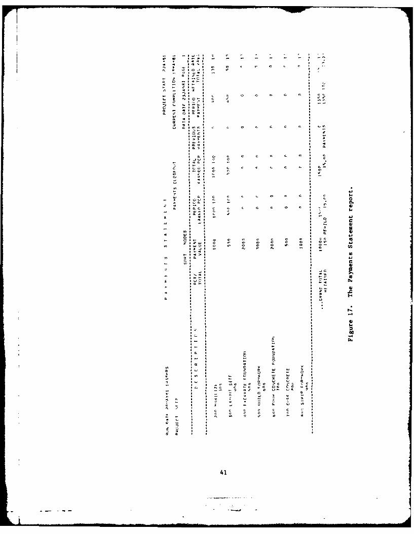
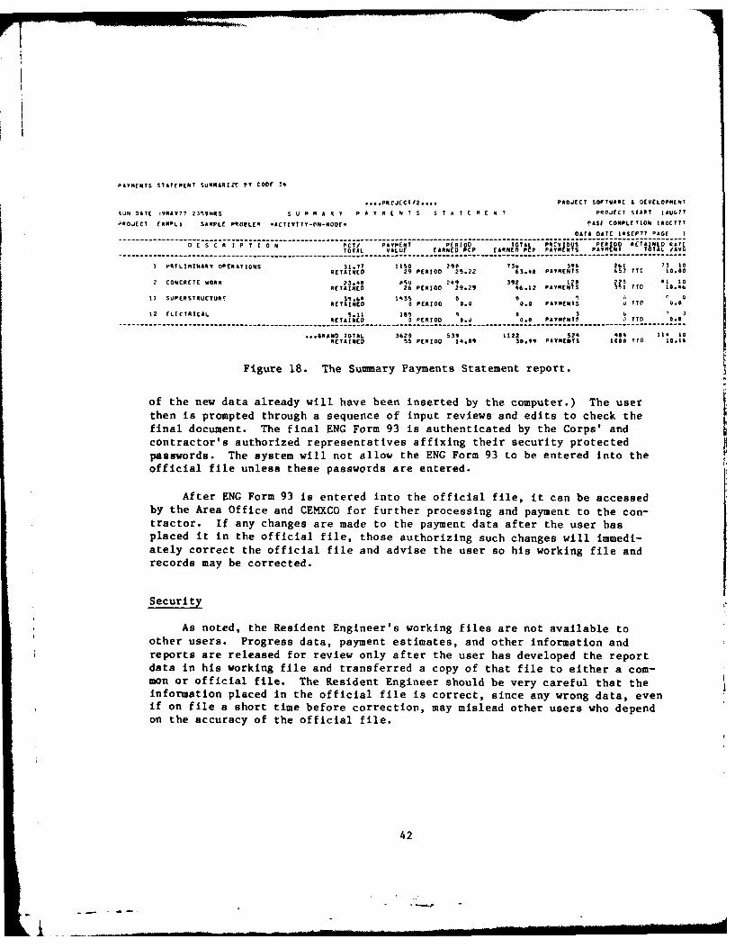
Screen 1432, Option 1 will produce the Payments Statement report (Figure17) and Option 3 will produce the Summary Payments Statement report (Figure18). The Payments Statement report shows the payment status of all theproject's activities; it also gives a grand total. This report, whichtranslates progress into dollars, is the detailed backup for the ENG Form 93payment document. The Summary Payments Statement report allows the user tosee the same information, but summarized into the activity groups he selects.The Payment Estimate report reflects the project status information input bythe user (Figure 19). Hard copies of the Payment Estimate and Payments State-ment reports should be kept in the Resident Engineer's files.
To display ENG Form 93 on the terminal screen, the user selects Screen1432, Option 2 (Figure 20). If this is the contract's first payment, the formwill be blank. For subsequent payments, the form is completed in the sameway, except new spaces will be designated for the new data. (Note that some
40
Ia' C CbS- - -4..j'~4 r - - - 4 . -.
p 4444* 4 , 'U -
-, ~ 4.4 4 C CU C p C C C 4
tC S ~ 4044 .. ,- 4jj4 .
Cl 4*C 4 4
- 2 4-Cl
a C' ~44~4 4 A.
a - ~4- 4
- C.44. 4 -
C ... 443 4~J **,4 4
- a ~ 4 C C C C C. C C 4 CC
4.. 1 t*j404-4 C 2 4 uS.*s.* C, * U'u.
) C. "44C"44 4 --
C .- iaY 4 I
a 2' 040.44..' 4 a,a * * *a *-4 4 4
.2 4 4 4
.o c4u~~4 C C C C C C C 4 CC.
* 0~4 4 -
024 4 2
* >14 4 14CC 4 4 -
* a 4 4 , *SaC S . a* 4 4
* 4 4
* 0 4 c. C e a C C. C 4 C
4..3L44 C C 4 C
- 4405 - 4
z 4- 4 . .rC 4CC4 C C C C C C C 4 C
4'- 44-444 C C- 4 0
4tC 4 Z 4 c 2 4 4'
0 4 34 - -
-.4 4 4'4 4
L) 4 Ut 4
* 4 4
CC 4 4- 4 4 47 , 4 4
* 04 C C C C. C C C. S C t~4
- 3 40(44 C. C 4 C 0- 4004 - - 4 * 0.
2 - 4 4 4 4'
a ,ac 4 C C C. C 0 C 4 - 6)44 444.4.4 C. I $4
4024 C 2 4 .,
I 4 24 - 4 -
* 44 4 0 a44 4 444 4 J
* 4 4 - 4)- 4 4 4 3 5* z: :
04 4 4 4.)
- 041- 4 0 C C C C C C 4 CC
rezuje C C C C C C C I CC atj~ 4U4D4 C U' C 0 C U' C 4 0-
43~J4 - N 9' 544
4444 4 -
- 4 4 C 4 4 0
n ala 4 4 a- U'4 * 4 0
* 1 4 4)4 4 9
4 -44 4 .JCINtl
4~ 4 4 CC 03 4C4C.4
C~40 - 4 4 - 4
C 4 4 4 -
4 4 4 C... 4)4 4 4 5 2>
* 4 4 4
0 4 4 4 2 1-.4 4 4 (1
4 4 4
4 4 4
4 4 4
* 4 4
4 4 4 4-'S
4 4 4
4 4 4
4 4 4 4)4 4 4 54Ii' 4 4
I... 00
4 4 - 4 -4C 4 - 4
4 4 - 4
4~ 4 - 4
4 4 4 4
40 4 C = 44 4 C4C 4 - - 45 4 - - 4
40 4 4 C 4
CC 4 4 C a 4 4
2 44.4 4 2 2 4'J "4 2 4
1 4 4 C C 0 4
4CC 4 4- C C "4 C £ I
- 4 4 .- a o 4
C SC' 4 - 2 4.4 CC 2 4
- 5 4 aC ICC "4C CC' CC CC- ~C 4
4C.. 4 P.C C CC aC CC CC .. C I
- 4 4 -- .- C 42' .0 (41- C'2 >4
2' 4 4 4 C. C a 4C 4 4 C. .4 1 U- - 4
4 4C 4 4 t (4 - Z 44 3 44 4 - - 4
C - 4 4 3 - . 0. C.' U) 4
'C .' 4 4 4
4 4 C C C C C C V 4
* 4 C C C C C C C 4
- - 4 4 N '54 44 2' 0 1- 4 4
4 C 4 4 4
C C 4 4 4
- 4 4 4
2 C. 4 g 4
2 2 4
2 0 4 * 4
41
C - -
PAYMENTS STATEMENT SUMMARIZE PY CODE !4
... PRTJECT/2 .... PROJECT SOFTWARE I DEVELOPMENT
RUN DATE 19MAY7' 2359MRS S U M M A R I P A Y N L N T S S T A I I M E N I PROJECT START jAUG??
PROJECT EXR4L1 SAMPLE PNOPLEM *ACTIVITT-YN-NODE. PASE COMPLETION 18OCIT
DATA DATE 14SEP77 PAGE I
0ESCNIPT10NPCT/ IAYPENT PE1RIODP TOTALP P1,,V I0tS PERIO RET 1AINE RATETOTAL VALUE CANE PCP ET P I N S PYE NT TOAL 1AYS
PRELIMINARY OPERATIONS 31.71 1110 290 73: 396 261 73 tONETAINED 29 PERIOD 25.22 63.4e PAYMENTS 657? TIC 10.00
2 CONCRETE WORK 23.4 5 4 392. 14 223 41 IIRETAINED 826 PERIOD 299.29 46.12 PAY4ENTS1 3-1I T 10..6
IS SUPERSTRUCTUR 39.6 1455 a A 0RETAINED 0 PERIOD 0.0 0.0 PAYMENTS ITOE (.00
12 ELECTRICAL "AID, is: q 0 2NETAINED 0 PERIOD l.J 0.0 PAYMENTY 1_TYD 0.0_
... RAMD TOTAL 5620 539 1122 524 404 114 10RETAINE D -55 PERIOD 14.89 30.99 PAYMENT S 114A IT 10.14
Figure 18. The Summary Payments Statement report.
of the new data already will have been inserted by the computer.) The userthen is prompted through a sequence of input reviews and edits to check thefinal document. The final ENG Form 93 is authenticated by the Corps' andcontractor's authorized representatives affixing their security protectedpasswords. The system will not allow the ENG Form 93 to be entered into theofficial file unless these passwords are entered.
After ENG Form 93 is entered into the official file, it can be accessedby the Area Office and CEMXCO for further processing and payment to the con-tractor. if any changes are made to the payment data after the user hasplaced it in the official file, those authorizing such changes will immedi-ately correct the official file and advise the user so his working file andrecords may be corrected.
Security
As noted, the Resident Engineer's working files are not available toother users. Progress data, payment estimates, and other information andreports are released for review only after the user has developed the reportdata in his working file and transferred a copy of that file to either a com-mon or official file. The Resident Engineer should be very careful that theinformation placed in the official file is correct, since any wrong data, evenif on file a short time before correction, may mislead other users who dependon the accuracy of the official file.
42
- -- ~j

C C I 40 C)-gz ct a - Io N
C- z -I0 C>0
w - I C
0- a NIu
-6 Li 30 0 0
4 C tI 0 0 0
C> CI c 0
00 Ia in I)L
Ian
* J C Cl
*r c. " :. -c #
z 3 c a c. C. C C 0 C C>3
C CP
1.10-I w 0 0 0 0 e
0.4 C C 0 C C . 0 C C C 3 43 ~

PAYMENT ESTIMATE - CONTRACT PERFORMANCE .DT
F or use of tis form, as ER 37 210 anl ER 37 345 10 ISHEET -of
2 CONTRACTOR AND ADDRESS 3 CONTRACT NO 14 DISTRICT
S DESCRIPTIONd OP WORK 6 APPROPRIATION AND PROJECT 7 REOUIRED COMPI E ION OATE
8 LOCATION 9 PERIOD COVERED BY THIS ESTIMATE TO JOB ORDER NO II ESTMAT NO
FROM THRU
ITEM CONTRACT TOTAL TO DATE
No DESCRIPTION OUANTITY AND U7N I T OUANTITY ANDUNIT PRICE AMOUNT UNIT AMOUNT
IF b 11 d
TOTAL EARNINGS
INCLUDES MODIFICATION THRU TOTAL CONTRACT - *STO DATE - * S
12 PRESENTED FOR PAYMENT 14 A PREVIOUS DEDUCTIONS OTHER THANPAYEE PRRETAINED PERCENTAGE
B PREVIOUS RETAINED PERCENTAGEX.
C~ PREVIOUS PAYMENTS _____
DATE TITLE0 PREVIOUS EARNINGS IA-B*CI
13 APPROVED FOR PAYMENT E EARNINGt THIS PERIOIO ITAL
I CRTFY11f Iflw 19I~W llA,93fl'I.1001.dbeII,.bil O .10191. 111 SP EARNINGS TO DATE MINUS DIICETIY ha Ihinihokod" sn~t@sfwobVIh~bifo "tmle1ht h LESS RETAINED PERCENTAGE____
.0, k wall actually Pvto-ld. th.t fhe .nnt are corrct anld consistent will all Wt - ..
.imsothO01lufat,ori as actually chocked that1 the 009019r.1 and Iallout. r wholly G LESS DEDUCTION OTHER THAN
conintI.l wrfl Fin, r,90awevis ofI the contract 0,other rismirfor,11 twoloed RETAINED PERCENTAGE FOR
HTOTAL DEDUCTIONS THIPEODF 0
SIGNATURE TLEDATE I RETAINAGE REFUNDED.J. OTHER RE FUNDS_______
K. TOTAL REFUNDS THIS PERIOD x::s::.:.:::
L AMOUNT DUE CONTRACTOR UEH.(
CONTRACTIN4G OFFICER APPROVAl ISvnature) DATE 15 RECAPITULATION
TOTAL RETAINED ECTG IB.F-11 S TOTAL PAID IC-LI S
ENG I MAR 7B PRE-O1Ij E0ITIOG THIPIS FORM IS OBSOlEIE -IUSE REVERSE SIDE P00 DEIILOEEPLANA11IIN AND OR REM.. ;S)
Figure 20. The Payment Estimate report -- sample 2.
Authenticating Passwords
Certain communications, reports, etc. mailed from the Resident Officeover the Resident Engineer's or other authorizing signature must be authenti-cated in the electronic medium by assigning passwords to authorizing individu-als in the Resident Office. The computer will not accept material into theofficial file unless it has the correct password. Access to material in theofficial file will also be controlled by passwords.
To maintain the security of the system, passwords will be changed fre-quently. The CEMXPA Management Support Group will assign passwords.
44

Individuals who are assigned passwords are responsible for their security andany transactions made under their authority. CEMXPA will immediately issue anew password when notified of a compromise.
Operational Passwords
Only a few key people will be assigned authenticating passwords. Otherauthorized system users will be issued operational passwords. The ResidentOffice will need an operational password to access the computer system and useits capabilities. The user will have to assign himself passwords to enter hisvarious working files. Various levels of passwords will be in use at the sametime for various purposes. Only those directly responsible for an activitywill be able to input and subsequently change stored data. Others, who have aneed to know, will only be able to read the data. Who has access to what andfor what purpose will be controlled through the password system.
Electronic Transfer
Screen 14, Option 4, starts the process of placing ENG Form 93 into theofficial file. Option 4 also can be used to reproduce and transfer specificmaterials developed in the working file (inaccessible to other users) intoanother file (e.g., the official file). Material is placed in the officialfile to give other users the information they need to do their jobs, or in thecase of the Payment Estimates report, to have others pick up the informationand continue its processing. The official file is the user's outgoing mailbox for much of his correspondence with higher organizational levels.
The official file contains only the latest data. For example, when auser enters Payment Estimate report No. 6 documentation, the previously storedNo. 5 documentation is destroyed.
Material placed in the official file is available immediately to author-ized users. In addition to sending things out via the official file, the useralso will receive messages electronically. When the user logs onto the sys-tem, general messages will appear. As the user selects subsequent options,messages pertinent to those options will appear.
Record Copies
Generally, the computer (particularly the official file), will store onlycurrent data. As the user updates or revises data, superseded data are des-troyed. If a historical record of the contract is desired, it must be createdby generating and filing hard copies of pertinent reports as the jobprogresses.
The Resident Office is responsible for maintaining the record files forits contracts. Among other things, this includes copies of ENG Form 93 andthe Payment Statement report.
45

.! ! "- ------ -
5 MODIFICATIONS AND CLAIMS
Change Orders
When the contractor's progress schedule was approved, the Corps acceptedit as a definition of a practical way to finish the work on time. As long asthe work remains unchanged and actual progress meets or exceeds thatscheduled, the originally approved progress schedule is viable. Unfor-tunately, it is often necessary to change the work. The Modification ImpactEvaluation Module, Module 15, helps the Resident Engineer determine the effecta change order will have on the contractor's approved schedule. Figure 21gives Module 15's flowchart. The screens supporting Module 15 shown in Appen-dix A, Figures A41 through A53. Module 15 also speeds the implementation ofschedule revisions which reflect change orders. It is essential to successfulcontract administration that the approved planning schedule be current.
The key to maintaining the planning schedule is prompt revision when achange order occurs. This cannot be done if the contractor responds late toan RFP or fails to negotiate the time element in good faith. However, thecomputer can quickly quantify the time element involved in the changed orunchanged work caused by a change order. Using this information (plusknowledge regarding the granting of additional time or buying back time tomeet a critical date), the time factor for a modification can be unilaterallyresolved. The contractor then can be notified (in the RFP) that he has xnumber of additional days to complete the changed work. Thus, the contractoris responsible only for developing the change order's dollar proposal. At thesame time, since the time has been quantified and network revisions identi-fied, the network can be input immediately with the new data (and be used toevaluate the impact of the next change order, if necessary).
Since change orders are not initiated unless they are absolutely essen-tial, there is very little danger that an RFP will not be followed by an exe-cuted modification. Consequently, there is little risk in revising the plan-ning schedule network before issuing a Notice To Proceed (NTP), or reaching adollar agreement. In the rare event that an RFP is withdrawn, the networkrevisions can be removed easily. Of course, any time element analyses basedon the withdrawn revisions would have to be reevaluated.
As change orders occur, there should be a way of identifying the networkactivities whose dollar value or duration are affected. Changes in existingactivities (and any new activities) will be identified in the contractor'sproposal, the resume of negotiations, the findings of fact, and the contractmodification documents. The B-code digits 789 code network revisions so theykeep their identity. This allows the computer-generated ENG Form 93 to eitherinclude earnings on modifications in the total earnings to date amount, or toseparately list earnings on modifications, at the user's option. The totalcontract amount will include the value of all executed modifications.
The network will be affected by factors other than the change orders. Itmay have to be revised because it no longer accurately represents thecontractor's plan for executing the work, or because actual progress has notkept up with the schedule.
46- -- .,

SMODIFICATIONI MPACTEVALUATIONMODULE 151
COPY ENTER STORE IN I PRINT REMOVE NET
NETWORK CHANGES ERROR-CHECK EVALUATION FROMTO WORKING TO WORKING CHANGED REPORTS WORKING
NETWORK 152 NETWORK 1531 FILE
I I
CHANGE I OUTPUT I OUTPUT I TO CHANGE/HOLIDAYS----- _J L REVISE"
1521 MODULE i1,6
REMOVE REMOVEACTIVITIES 1RELATIONSHIPS
/CONSTRAINTS
1522 1523
ADD ADD
ACTIVITIES RELATIONSHIPS/CONSTRAINTS
1524 1525
CHANGEACTIVITIES
1526
Figure 21. Module 15 -- flowchart.
Any revised logic or durations must be developed by the contractor and
submitted for approval. After the revisions are input, the computer produces
a new official Planning Network report. This new schedule then is the basis
for evaluating the effect of subsequent changes, if any. Since the snowbal-
ling effect of unresolved modifications makes it less likely that a truly
equitable adjustment can be achieved on any single modification, change orders
must be handled one at a time. Since they may come quite rapidly during a
project, the system and its users must be prepared to process them quickly.
But issuing an NTP simultaneously with the RFP should be reserved only for
truly urgent situations. It should not be used as a parvcea to relieve the
pressure to properly process the change in a short time.
47

Because the Modification Impact Evaluation Module lets Resident Engineersquickly analyze the time impact of change orders, delays in "plugging" changesinto a schedule can be avoided. This eliminates the problem of having toevaluate the effect of Modification 5 when the planning schedule has not beenupdated to reflect the changes caused by Modifications 1, 2, 3, and 4. Fol-lowing up with the dollar agreements also is made less difficult becauseactivities both directly affected and indirectly affected (i.e., the unchangedwork) are identified.
Impact Analysis
To estimate the effect of a change order, the current status of the workand the contractor's approved plan for completing the remaining activitiesmust be known. The Modification Impact Evaluation Module provides this infor-mation. It also lets anticipated network adjustments to be temporarily (orpermanently) input and their effect observed. Screen 15 (Figure A41) offersoptions that let the user:
i. Obtain copies of the current approved planning schedule.
2. Input appropriate changes to the network; i.e., delete activities,create new activities, change durations, change descriptions, etc.
3. Process revised data.
4. Obtain reports (standard or customized) to compare the new scheduleto the old schedule.
5. Copy all or part of anything produced before restoring the files to
their original condition.
6. Keep all or part of the revised reports for use in justifying thetime element involved in the change order.
7. Keep the revised input in the system, thus making a new planning
schedule available for official approval and implementation.
The change order's time effects can be observed by comparing the current
Target Date report to the Target Date report generated after the changes tothe network have been input to the working file and processed. At this point,it is known whether the change order work normally would delay the completionof the remaining work (or any critical part of it), and, if so, quantify thedelay. (Whether the time extension actually will be granted is a managementdecision influenced by broader considerations.) This analysis will show thoseactivities both directly and indirectly affected by the change order; estimat-ing the dollar cost of the change order must take both into consideration.The estimate must also consider that time has value, whether or not it is onthe critical path.1
1 For examples of using the NAS to develop the modification estimates, see
Modification Impact Evaluation Guide, Engineer Pamphlet (EP) 415-1-3 (Officeof the Chief of Engineers, July 1979).
48
- *~~0
Computer support speeds the assessment of the effects of time on aschedule, even for a large network and complex change order. As noted, changeorders are not the only reasons an original plan is amended. For example,when the contractor falls behind the approved schedule, and the officialschedule no longer reflects the time needed to finish the remaining work percontract requirements, the contractor must submit a revised schedule. Ordi-narily, only the durations or the sequencing of the remaining activities willbe changed, with shortened durations implying the assignment of increasedresources by the contractor. No increase in contract price or the value ofthe various activities is permitted, since the need for schedule revislonstems from contractor-responsible causes. After the Corps reviews andapproves the revised schedule, it becomes the new official schedule.
Request For Proposal (RFP)
An RFP should define the time, if any, allocated for a change order toachieve the following benefits:
1. Reduce the time needed to reach agreement with the contractor on theprice of a change order.
2. Permit prompt revision of the progress schedule to accommodate the
changed work.
3. Maintain the contractor's incentives for efficiency.
4. Allow equitable handling of a large number of change orders.
A computer-supported NAS allows the user to predict time impacts, and to docu-ment his findings. For those findings to be reasonably accurate, the usermust use good judgment in deciding where in the sequence of events the newwork could and should be accomplished. He also must decide how long thechange will take, considering the normal workweek, the other work, andresources available to the contractor. The contractor's only responsibilityis to price the work appropriately for the specified timeframe (like he didwhen he bid the original contract work).
The RFP also should contain other pertinent information such as the dateby which the contractor's proposal will be received, any instructions concern-ing coordinating the cost proposal with network activities, and the separationof direct costs from impact on unchanged work. The contractor should be toldwhether the progress schedule is unchanged or revised (see Appendix C).
Finalization
It is easier to arrive at an equitable adjustment on the price of achange order if the price is negotiated separately from the time element. Itis best to agree on the time and price of a change order before the changedwork begins. If the contractor does not cooperate with a prompt, responsive,reasonable proposal, unilateral modification may be used.
49

The modification document should state that the agreed price includes allamounts due the contractor for the changed work, and show the portions of thecost attributed to directly changed work and impact. If no impact costs areinvolved, the modification should so state.
Network Revisions
A construction contract can have only one official progress schedule.That schedule remains in force until the Resident Engineer approves a revi-sion; then the revised schedule becomes the official schedule. TheCorrect/Revise Stored Network Module, Module 12, lets the user (1) revise anetwork after it has been stored in PROJECT/2, (2) check the results of hisrevision, and (3) place the revised network into the official file. Thescreens supporting Module 12 are shown in Appendix A, Figures A54 through A66.
Module 12 helps the user input network changes and place the revised pro-gress schedule into the official file after he has selected the best way toincorporate change order work or he has reviewed and accepted a revised planfrom the contractor. For change orders, the network is revised when the RFPis issued (it is not necessary to wait for a dollar agreement). For planningchanges requested by the contractor, the official schedule is updated when theResident Engineer approves the contractor's revised plan. In either case, thecontractor is told of any schedule revisions through the RFP (for change ord-ers) or the regular approvals procedures (for contractor-initiated networkrevisions). The rest of the system's users are informed by transferring thenew, approved schedule to the official file.
Claims
General
All claims submitted by the contractor must be carefully evaluated. Ifthe claim is justified, it will generate a contract modification, throughwhich an equitable adjustment may be reached. All changes must be resolvedpromptly, whether they are initiated by the Corps or the contractor (claim).
2
Claims cause contract modifications, are withdrawn by the contractor, or aredenied via a contracting officer's decision. Regardless of the ultimatedisposition of a claim, some review of the job's history usually is required.Job status records and computer-generated reports can help reconstruct theconditions that prompted the claim. Networking capabilities also can helpanalyze claims that affect future job activities.
Impact Analysis
The only difference between analyzing the effect of the change alleged ina claim and that of a change order issued by the Corps is the time in whichthe effect begins. A claim's effect may have begun before the claim notice isreceived. (See the section titled Chanve Orders, above.)
2 For policy and procedures, see Modifications and Claims Guide, EP 415-1-2
(Office of the Chief of Engineers, July 1979).
50

Resolution
Claims are either accepted, denied, or withdrawn. Accepted claims are
resolved through the change order process. Denied claims do not always staydenied; if the contractor submits the claim without asking for a contractingofficer's decision, if appropriate, the Resident Engineer may deny the claim
and support his position with appropriate documentation. The contractor maythen withdraw his claim or request a contracting officer's decision. The con-tractor may also appeal a contracting officer's decision that denies hisclaim. The contractor may withdraw his claim at any time.
51

6 SUPPLEMENTAL MODULES
User Message Module
The User Message Module, Module 18, lets system users communicate elec-tronically with all other (or selected) system users. A flowchart for Module18 is shown in Figure 22. The screens supporting Module 18 are shown inAppendix A, Figures A67 through A73. Module 18 supplements the electronicinformation transfer abilities used for construction scheduling, progress, ardpayments provided by the system's other modules. The User Message Module isintended primarily for text, but also can be used to circulate statisticaldata. Whatever message the originator wishes to transmit becomes availableinstantaneously at the terminal of those the originator selects to receive it.
All messages are identified by a serial number, the originator's identif-iction, a date, and a recipients' list. Originators may remove their messagefrom the list at any time. Recipients will electronically acknowledge theyhave received a message. The system will automatically remove any messagesmore than 15 days old.
The computer will automatically assign each message a number when it isentered into the system. This numbering system is designed and managed toprevent duplicate numbers.
System security is maintained by requiring password authentication beforean originator's messages are dispatched. This will inhibit pranksters andpractical jokers, who otherwise might destroy system credibility. The systemis not suitable for transmitting classified information.
The module's initial screen, Screen 18, lists options coordinated withsystem functions (Figure A67).
PROJECT/2 Access
The full PROJECT/2 Access Module, Module 17, is for users who wish toexpand the capabilities of the MX Construction Planning Management System andwho are familiar with PROJECT/2 processors, their command language, and proto-
col. (A PROJECT/2 flowchart is shown in Figure 23. The Module 17 screen isshown in Appendix A, Figure A74.) This module places the full capabilities ofPROJECT/2 at the user's disposal. Unlike other system modules, it requires athorough knowledge of PROJECT/2 command structures.
The other modules in the system use PROJECT/2 by working through anintermediary software package that translates more or less familiar terms andcommands into a language understood by PROJECT/2. These modules give the userenough processing and reporting options to perform all networking functions.So, under normal circumstances, most users will not need to access PROJECT/2directly.
52
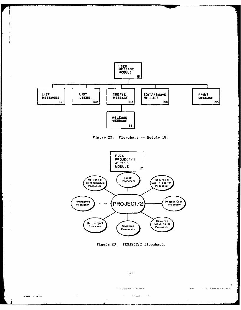
MSAEMESSAGE
FUL
AESSMDULE
Figure 2. FRJ/ lowchart oue1.
53L
PR ...-.- ,

OFFICESUPPORTMODULE
19
WORD UNIT TECHNICAL POLICY 8 SHOP
PROCESSINGPRICE INFORMATION PROCEDURES DRAWINGPOESNDAAMANUAL '9 / REGISTER
1911 1DT 192 193 MAUL19 E 195
PAYROLL BSX/CSI 8 OFFICE MODIFICATIONRECORDS DESCRIPTIONS DATA STATUS
(96 197 198 199
Figure 24. Module 19 -- flowchart.
Office Support Module
Many construction field officer functions can be done better and quickerwith the computer support offered by the Office Support Module, Module 19. A
flowchart for Module 19 is shown in Figure 24. The Module 19 screen is shown
in Appendix A, Figure A75:
I. Word Processing. This submodule helps prepare correspondence andforms not otherwise automated. It requires its own dedicated terminal and
processor.
2. Unit Price Data. This submodule can generate and update a list of
unit prices from Government estimates, bid breakdowns, change order settle-ments, etc. It is adjusted to geographical area.
3. Technical Information. This submodule can access stored text such as
American Society for Testing and Materials (ASTM) standards, Federal specifi-
cations, and other reference material.
4. Policy and Procedures Manual. This submodule can access stored,indexed, and keyworded CEMXPA regulations, circulars, forms, pamphlets, etc.
Material can be called up and read from the CRT screen or printed, eliminating
the need to distribute the same data in hard copy to all offices.
5. Shop Drawing Register. This submodule can set up a tracking system
to help the office engineer control submittal activities, and maintain recordsof value in the event of claims.
6. Payroll Records. This submodule can store and process payroll data,both for the contractor (if required) and the Government.
54

7. BSI/CSI and WBS Description. This submodule can list Building SystemIndex (BSI) and Construction Specification Institute (CSI) codes and descrip-
tions, and generate an indented hierarchical listing of the MX deployment workbreakdown structure (WBS). (The MX coding system must be uniformly applied toconstruction networks to allow this integration.)
8. Office Data. This submodule offers miscellaneous packages to helpflag vehicle preventive maintenance, maintain an inventory of accountable
Government property, prepare and distribute DD Form 1354s and associatedmaterials, etc.
9. Modification Status. This submodule offers a package to help managechange orders: lists per contract, per stage, per all contracts assigned tothe office, per contracts more than 75 percent complete, etc. It also helps
establish priorities for assigning resources to problem areas.
The minimum Office Support Module should contain the Word Processing and
BSI/CSI and WBS Description submodules. Expansion will depend on the size andmission of the office and the operating procedures implemented by the ResidentEngineer.
55

7 CONCLUSION
The Network Analysis System (NAS) provides an effective and versatilemeans of planning, managing, and monitoring construction. The Corps is com-
mitted to its use on all but its very smallest projects. Through the use ofhierarchical networking, the significant elements of a number of individualprojects can be combined to produce summary data for major programs. Effi-
cient application of these principles, even on moderately sized projects,requires real time or near real time computer support. PROJECT/2 (an NASsoftware package developed by Project Software & Development, Inc.) has beenselected for use on the MX program.
This report has described and provided user guidance on an MX Construc-
tion Planning Management System based on NAS and PROJECT/2. The system isoriented toward the needs of the Corps MX Area/Resident offices, while at thesame time providing higher echelon management information needed for theirfunctions. Although the system was developed to satisfy the management needsof the MX program, it is equally applicable to other Corps projects and pro-grams.
56
- . . . . . . .- . . . ... . . . . .. .. . . . . . . . . .. . . . . . . .

APPENDIX A:
MX CONSTRUCTION MANAGEMENT SYSTEMMODULE SCREENS
57
----. 1
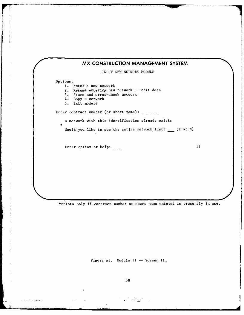
MX CONSTRUCTION MANAGEMENT SYSTEM
INPUT NEW NETWORK MODULE
Options:1. Enter a new network2. Resume entering new network -- edit data3. Store and error-check network4. Copy a network5. Exit module
Enter contract number (or short name):
A network with this identification already exists
Would you like to see the active network list? (Y or N)
Enter option or help: - 11
*Prints only if contract number or short name entered is presently in use.
Figure Al. Module Ii -- Screen 11.
58

MX CONSTRUCTION MANAGEMENT SYSTEM
INPUT NEW NETWORK MODULE
Network:
Header Data
Contract Title:
Contractor's Name:& Address:
Area Office:
Network Type (A/A or A/N):Contractual Start Date:Contractual Completion Date: / /Working Days Per Week:*Holidays (Standard, Government, Manual Loading):
Options: 1. Assign Code Descriptions2. Edit Data3. Exit Module
Enter option or help: __1
*"Manual Loading" option selects menu lii
"Network Type" selection determines input screen series: for activity on
arrow (A/A), screens 1115 and 1117; or for activity on node (A/N) screens
1114, 1116, and 1113.
Figure A2. Module 11 - Screen 111.
59

II
MX CONSTRUCTION MANAGEMENT SYSTEM
INPUT NEW NETWORK MODULE
Network:
Assign holidays (DDMMMYY):
Options: 1. Assign more holidays2. Return to header menu
3. Assign code descriptions
Enter option or help: 1111
Figure A3. Module 11 -- Screen 1111.
60

MX CONSTRUCTION MANAGEMENT SYSTEM
INPUT NEW NETWORK MODULEGLOBAL CODES
Network:
The following global code descriptions are required for contract networks tointegrate with higher level networks. They may also be used for internaloffice networks.
Code Field Description Code Field Description
A12 BSI B123 Facility IDA34567 CSI B45 Subfacility*A89 Subcont. ID B6 Responsibility
**B789 Modification ID
(*Optional input by contractor, **optional use by government.)
Options: 1. Enter optional code descriptions2. No optional codes used, proceed to network data input3. Exit module
Enter option or help: 1112
Figure A4. Module 11 -- Screen 1112.
61
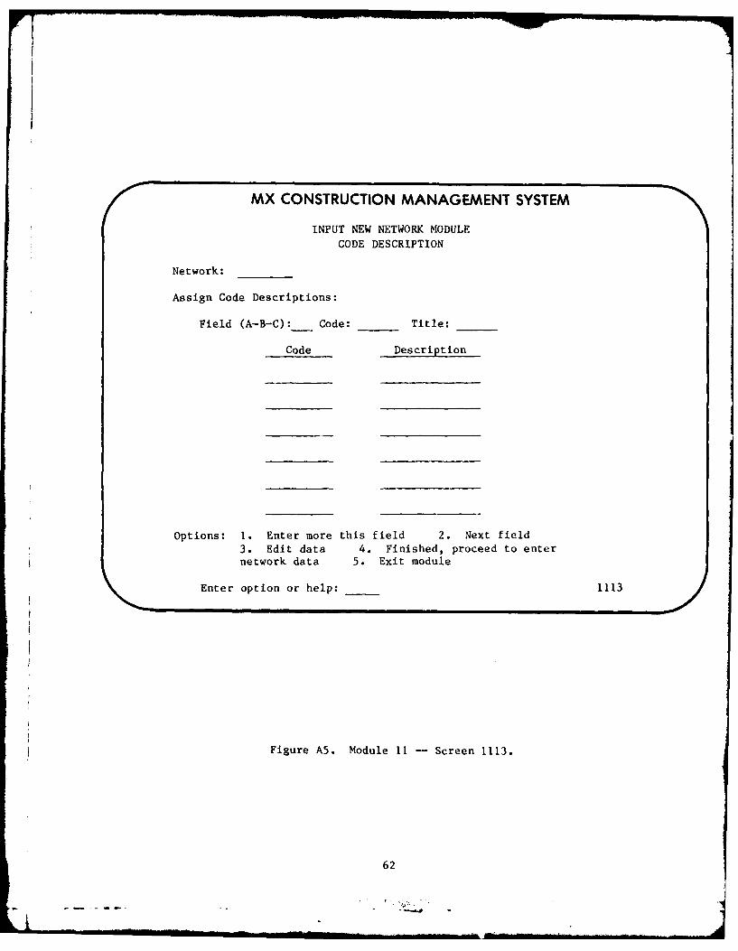
MX CONSTRUCTION MANAGEMENT SYSTEM
INPUT NEW NETWORK MODULE
CODE DESCRIPTION
Network:
Assign Code Descriptions:
Field (A-B-C):__ Code: Title:
Code Description
Options: 1. Enter more this field 2. Next field3. Edit data 4. Finished, proceed to enternetwork data 5. Exit module
Enter option or help: 1113
Figure A5. Module 11 -- Screen 1113.
62

MX CONSTRUCTION MANAGEMENT SYSTEM
INPUT NEW NETWORK MODULE
Network: _____
Enter activities and events -A/N-
Node: _____Description: ___ _____________
Duration: Codes: _ __ ___ ___Value: _____
- REPEAT -
- REPEAT -
- REPEAT -
Options: 1. Enter more 2. Edit data 3. Enter
relationships 4. Store network 5. Exit module
Enter option or help: _ __1114
Figure A6. Module 11 -- Screen 1114.
63

/0000 MX CONSTRUCTION MANAGEMENT SYSTEM
INPUT NEW NETWORK MODULE
Network: _____
Enter activities and events -A/A-
Description:___________________________
Duration: Codes: _ __ ___Value: ____
- REPEAT -
- REPEAT -
Options: 1. Enter more 2. Edit data 3. Enter contraints4. Store network 5. Exit module
Enter option or help: 1115
Figure A7. Module 11 -- Screen 1115.
64
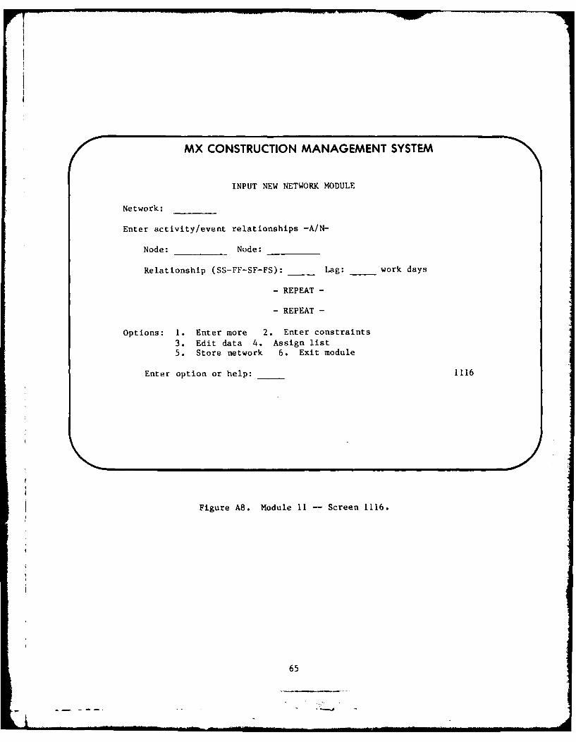
MX CONSTRUCTION MANAGEMENT SYSTEM
INPUT NEW NETWORK MODULE
Network:
Enter activity/event relationships -A/N-
Node: Node:
Relationship (SS-FF-SF-FS): _ Lag: work days
- REPEAT -
- REPEAT -
Options: 1. Enter more 2. Enter constraints
3. Edit data 4. Assign list5. Store network 6. Exit module
Enter option or help: 1116
Figure A8. Module 11 -- Screen 1116.
65

MX CONSTRUCTION MANAGEMENT SYSTEM
INPUT NEW NETWORK MODULE
Network:
Assign constraints -A/A-
(Note contractual start and finish dates have been entered.)
I J
Constraint (STArt - FINish): (ON-NET-NLT): Date:
- REPEAT -
- REPEAT -
Options: 1. Enter more 2. Edit data 3. Assign list
4. Store network 5. Exit module
Enter option or help: 1117
Figure A9. Module 11 -- Screen 1117.
66

MX CONSTRUCTION MANAGEMENT SYSTEM
INPUT NEW NETWORK MODULE
Network:
Assign constraints -AIN-(Note: Contractual start and finish dates have been entered.)
Node:
Constraint (STArt - FINish - EVEnt): (ON-NLT-NET):
Date:
- REPEAT -
- REPEAT -
Options: 1. Enter more 2. Edit data 3. Assign list
4. Store network 5. Exit module
Enter option or help: 1118
Figure AIO. Module 11 - Screen 1118.
67
- -....

MX CONSTRUCTION MANAGEMENT SYSTEM
INPUT NEW NETWORK MODULERESUME/EDIT INPUT
Network:
Options:
1. Edit previously input data2. Add to previously input data3. Edit and add to previously input data4. Delete all data stored under network name above.
Note: This module is operational only on network data not already submitted
to Project 2 for processing and storage.
5. Exit module
Select option or help: 112
Options 1, 2, and 3 will return user to screen 111 with previously input datashown as the inputing sequence is recycled.
Figure All. Module It -- Screen 112.
68

MX CONSTRUCTION MANAGEMENT SYSTEM
INPUT NEW NETWORK MODULE
Network:
Submit network to Project 2 for processing, error-check, and storage.
Select output:
Planning schedule, sort I-J (Y or N)
Planning schedule, sort ES-LF-FLoat
Network listing (Y or N)Other (Y or N)
Options: 1. Exit module 2. Edit data 3. Process network
Select option or help:
*Enter password: 113
*Appears upon selection of Option 3. If no specific output is selected,
default is Planning Schedule, l-J sort. "Other" output selection calls up
Screen 162.
Figure A12. Module 11 -- Screen 113.
69
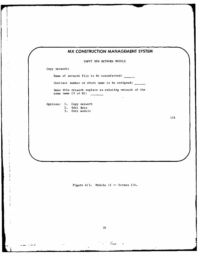
MX CONSTRUCTION MANAGEMENT SYSTEM
INPUT NEW NETWORK MODULE
Copy network:
Name of network file to be transferred:
Contract number or short name to be assigned:
Does this network replace an existing network of thesame name (Y or N):
Options: 1. Copy network2. Edit data3. Exit module
114
Figure A13. Module 11 -- Screen 114.
70
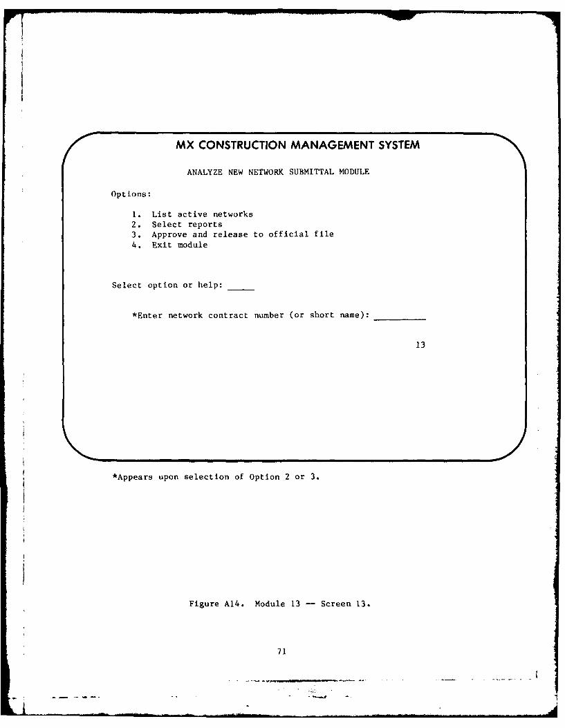
F7
MX CONSTRUCTION MANAGEMENT SYSTEM
ANALYZE NEW NETWORK SUBMITTAL MODULE
Options:
1. List active networks2. Select reports3. Approve and release to official file4. Exit module
Select option or help:
*Enter network contract number (or short name):
13
*Appears upon selection of Option 2 or 3.
Figure A14. Module 13 -- Screen 13.
71
] .... . . ., i,. - -... .. .. .. . ii ...

MX CONSTRUCTION MANAGEMENT SYSTEM
ANALYZE NEW NETWORK SUBMITTAL MODULE
ACTIVE NETWORKS
Contract # or
Short Name Data Date File Location
LIST LIST LIST
Options: 1. Next page 2. Previous page 3. Exit module
Enter option or help: _ 131
Figure A15. Module 13 - Screen 131.
72

MX CONSTRUCTION MANAGEMENT SYSTEM
ANALYZE NEW NETWORK SUBMITTAL MODULESELECT REPORTS
Options:
1. Basic submittal review package
Network listing - sort I-J - ejected and sorted BSI/CSINetwork listing - sort decreasing duration
Network listing - sort decreasing costPlanning schedule - sort I-JPlanning schedule - sort ESPlanning schedule - sort FLoat
Planning schedule - sort LFCost analysis (graphs)
2. Customized reports
3. Exit module
Select option or help: Enter network ID:
132
Figure A16. Module 13 -- Screen 132.
73

MX CONSTRUCTION MANAGEMENT SYSTEM
ANALYZE NEW NETWORK SUBMITTAL MODULE
Copy approved network to official file -
Network ID:
Enter password to start procedure:
Password:
Options: 1. Execute copy procedure
2. Edit data3. Exit module
Enter option or help: ___33
133
Figure A17. Module 13 -- Screen 133.
74
--.. -

MX CONSTRUCTION MANAGEMENT SYSTEM
PROGRESS REPORTING/PAYMENT MODULE
Enter network ID:
Options:
1. Print update input report
2. Enter/edit progress data3. Prepare payment estimate
4. Release payment estimate to official file
5. Exit module
6. Exit system
Enter option or help:14
Figure A18. Module 14 -- Screen 14.
75
77-7-
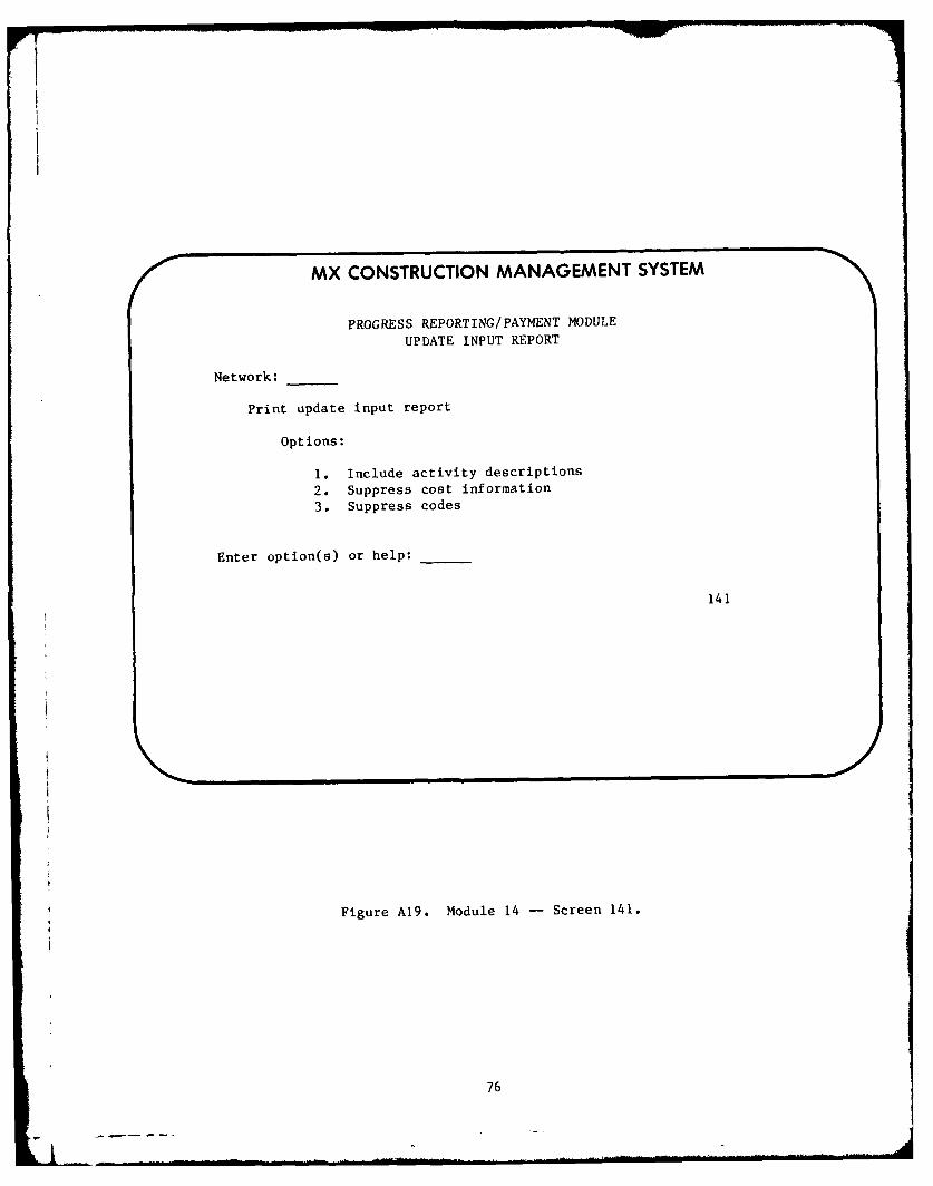
MX CONSTRUCTION MANAGEMENT SYSTEM
PROGRESS REPORTING/PAYMENT MODULE
UPDATE INPUT REPORT
Network:____
Print update input report
Options:
1. Include activity descriptions
2. Suppress cost information
3. Suppress codes
Enter option(s) or help:
141
Figure A19. Module 14 -- Screen 141.
76

MX CONSTRUCTION MANAGEMENT SYSTEM
PROGRESS REPORTING/PAYMENT MODULE
ENTER/EDIT PROGRESS DATA
Network:
Data Date:
Options:
1. Enter progress data2. Change/review progress data
3. Place progress data in official file4. Exit module
Enter option or help:
142
t/
Figure A20. Module 14 -- Screen 142.
77

MX CONSTRUCTION MANAGEMENT SYSTEM
PROGRESS REPORTING/PAYMENT MODULEENTER PROGRESS
Network: Data Date:
Activity No. Start Days % Rem FinishDate Compl. Compl. Dur Date
Options: 1. Enter more 2. Review/edit input
3. Exit module
Enter option or help:
1421
Figure A21. Module 14 -- Screen 1421.
78
Ai

MX CONSTRUCTION MANAGEMENT SYSTEM
PROGRESS REPORTING/PAYMENT MODULEREVIEW PROGRESS INPUT
Network: Data Date:
Activity No. Start Days % Rem Finish
Date Compl. Compl. Dur Date
-(PREVIOUS ENTRY)-
(CURRENT ENTRY-THIS ONE CAN BE MODIFIED)
(NEXT ENTRY)
Options: 1. Next entry
2. Previous entry3. Modify current entry4. Place progress data in official file
5. Exit module
Enter option or help: _ 1422
Fiiure A22. Module 14 -- Screen 1422.
79
________.

MX CONSTRUCTION MANAGEMENT SYSTEM
PROGRESS REPORTING/PAYMENT MODULEPREPARE PAYMENT ESTIMATE
Network:
Options:
1. Enter payment instructions2. Print payment documents3. Exit module
Enter option or help:
143
Figure A23. Module 14 - Screen 143.
80

MX CONSTRUCTION MANAGEMENT SYSTEM
PROGRESS REPORTING/PAYMENT MODULEPAYMENT INSTRUCTIONS
Network:
Estimate No. ____ Period: From To
Retainage __% of total earnings this period (Y or N)of activities coded
Value of materials on site: $_____
Deductions other than retained percentage: $_ ___Description: _____________________________
Retainage refund: $_ ___
Other refund: $ ____
Description: _______________________________
Options: 1. Edit input 2. Enter data to working file
3. Exit module
Enter option or help: ____1431
Figure A24. Module 14 -- Screen 1431.
81

!I
MX CONSTRUCTION MANAGEMENT SYSTEM
PROGRESS REPORTING/PAYMENT MODULE
PRINT PAYMENT DOCUMENTS
Network: Estimate No.
Period: From To
Options
1. Print payments statement2. Print Eng Form 93
3. Print payment estimate4. Print all of the above5. Exit module
Enter option or help:
1432
Figure A25. Module 14 -- Screen 1432.
82

MX CONSTRUCTION MANAGEMENT SYSTEM
PROGRESS REPORTING/PAYMENT MODULERELEASE PAYMENT ESTIMATE TO OFFICIAL FILE
Network: _____Estimate No._____
Period: From To
Amount Due Contractor: $ ____
Options: 1. Edit input2. Exit module3. Release estimate to official file
Enter option or help: __....
Enter password: ____
Password is accepted -- estimate is entered
t*
Invalid password -- check your authorization -- try again.
144
*Password Is required to enter data in official file, Option 3.Appropriate statement appears upon entering password.
Figure A26. Module 14 -- Screen 144.
83

MX CONSTRUCTION MANAGEMENT SYSTEM
REPORTS MODULE
Network:
Options:
1. Assign system settings2. Print reports3. Generate interactive reports display
4. Interactive reports display5. Draw network6. Draw barchart7. Exit module
Enter option or help:16
Figure A27. Module 16 - Screen 16.
84

MX CONSTRUCTION MANAGEMENT SYSTEM
REPORTS MODULESYSTEM SETTINGS
Network:
Schedule (ORIginal - CURrent):Precedence/Dummies (ON-OFFT-
Holidays (ON-OFF):Calendars (ON-OFF):
Constraints (ON-OFF):Lists (ON-OFF):
Header (ON-OFF):
Report Type (FULL-BRIEF):
Options: 1. Print reports 2. Exit module
Enter option or help:
161
Figure A28. Module 16 - Screen 161.
85

MX CONSTRUCTION MANAGEMENT SYSTEM
REPORTS MODULE
Network ID:
Options: 1. Network listing2. Executive milestone report3. Planning schedule reports (print-plot)4. Working schedule reports (print-plot)
5. Project status report6. Performance evaluation reports (print-plot)7. Current status reports8. Cost analysis reports (print-plot)9. Predicted status reports
10. Exit module
Enter option or help:
162
Figure A29. Module 16 -- Screen 162.
86

MX CONSTRUCTION MANAGEMENT SYSTEM
REPORTS MODULESPECIFY MODIFIERS (1)
Network:
Range:
Beginning (DD-MMM-YY):BeforeEndingAfterBetween and
*Interval (week,month, etc):
Options: 1. Continue 2. Exit module
Enter option or help:
1621
*Appears only for "plot" reports
Figure A30. Module 16 - Screen 1621.
87

MX CONSTRUCTION MANAGEMENT SYSTEM
REPORTS MODULESPECIFY MODIFIERS (2)
Network:
Options:
1. Select by activities2. Select by codes3. Select by time4. Select by cost5. Additional selections6. Selection complete7. Cancel selections -- exit module
Enter option or help:
1622
Figure A31. Module 16 -- Screen 1622.
88
Ll"

MX CONSTRUCTION MANAGEMENT SYSTEM
REPORTS MODULE SPECIFY MODIFIERS (3)
Network:
Select Activities with
(any) (A) (B)
Options "A": ES-LS-EF-LF-TF-DUR
Options "B": EQ-NE-LE-LT-GE-GT - AND DD-MMM-YYBET - DD-MMM-YY - AND DD-MMM-YY
Options: 1. Additional selections2. Selection complete3. Cancel selection - exit module
Enter option or help:
1623
Figure A32. Module 16 - Screen 1623.
89

MX CONSTRUCTION MANAGEMENT SYSTEM
REPORTS MODULE
SPECIFY MODIFIERS (4)
Network:
Do you want the report ejected into subreports: (Y or N)
Primary sort 2nd sort: 3rd sort:
Available sorts:
TF TDU TRL PCPA Code O;4m(N)Om_ CES TES COST PVB Code CLS TLS AC
C Code CEF TEF DC
I-J or NodesJ-I CLF TLF ETCES CTF TTF LRELS PCT TRF OBEF RD TRE PCCLF
Options: 1. Submit report 2. Exit module3. Next report
Enter option or help: 1624
Figure A33. Module 16 -- Screen 1624.
90

MX CONSTRUCTION MANAGEMENT SYSTEM
REPORTS MODULE
SELECT PROCESSING MODE
Options: Response Time Cost Factor
1. Interactive 5 sec 2
Batch2. Priority 10 1 hr 1.53. Priority 9 2 hrs 1.254. Priority 7 4 hrs 1.05. Priority 5 8 hrs .956. Priority 3 12 hrs .9
7. Priority 1 24 hrs8. Exit module9. Print reports
Enter option or help:
1625
Figure A34. Module 16 - Screen 1625.
91
... .,. '= I - - -- .... . . ll .... - .. .. -" . . .- . .. .. - - IT 1 [ . . . . . . . .II . . . . . .. .

MX CONSTRUCTION MANAGEMENT SYSTEM
REPORTS MODULE
OUTPUT LOCATION
Select location for output to be printed
1. At your terminal (turn on printer)2. At nearest high speed printer enter remote ID:3. At other remote locations enter remote IDs4. Combinations of the above, specify5. Exit module
Enter option or help:Enter password:
Enter network ID:
1626
Figure A35. Module 16 -- Screen 1626.
92
'--I

MX CONSTRUCTION MANAGEMENT SYSTEM
REPORTS MODULE
Job 4302 has been submitted for execution
Options: 1. Status jobs 2. Exit module
Enter option or help:
1627
Figure A36. Module 16 -- Screen 1627.
93
. . . -.. . -... . .

MX CONSTRUCTION MANAGEMENT SYSTEM
REPORTS MODULEINTERACTIVE REPORT DISPLAYING GENERATOR
Network:
Select available "BROWSE" reports:
1. Print schedule2. Print working schedule3. Print target schedule4. Print current status5. Print cost
6. Print actual cost
Enter option, exit or help:
163
Report modifiers are selected beginning with Screen 1621.
Figure A37. Module 16 -- Screen 163.
94
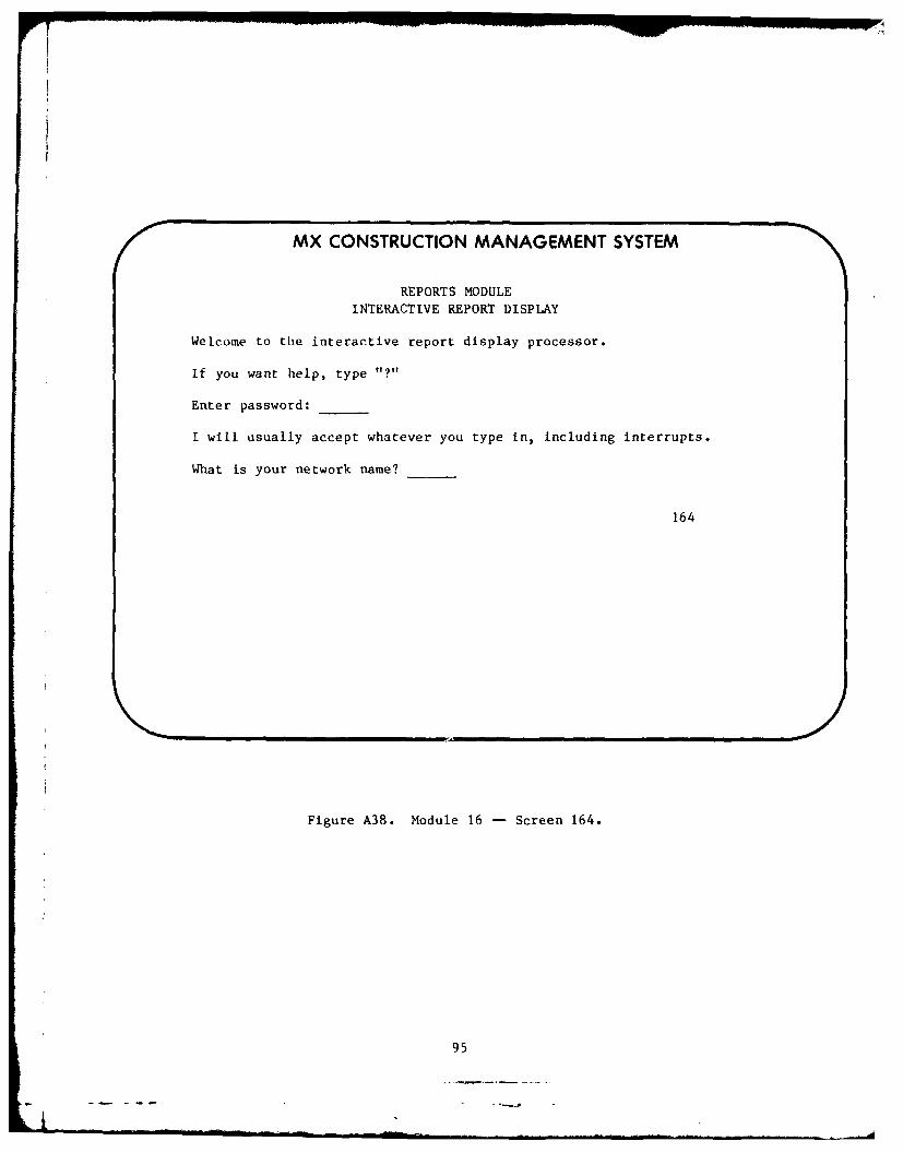
MX CONSTRUCTION MANAGEMENT SYSTEM
REPORTS MODULE
INTERACTIVE REPORT DISPLAY
Welcome to the interactive report display processor.
If you want help, type "?"
Enter password:
I will usually accept whatever you type in, including interrupts.
What is your network name?
164
Figure A38. Module 16 - Screen 164.
95

'AD-A116 730 CONSTRUCTION ENGINEERING RESEARCH LAB (ARMY) CHAMPAIGN IL F/G 5/1p MX RESIDENT ENGINEER NETWORKING GUIDE.dUIAPR !2R M J O-CONNOR. B E COLWELL IAO-EG7-81-7151
UNCLASSIFIED CERL TRP_126 NL

MX CONSTRUCTION MANAGEMENT SYSTEM
REPORTS MODULEDRAW REPORTS
Network:
Specify drawing (network) type:
(LOGic - COMpress - DIScrete - LINear)
Optional sheet title: _
Sheet size: Y (plotter width less 1 in.) in.X (optional) in.
Criticality (red ink) (ON-OFF)
Include off page connectors (ON-OFF):
Assign zones (CODE set - FLOAT):
Scale:
Options: 1. Select modifiers 2. Print 3. Exit module
Enter option or help: 165
Figure A39. Module 16 - Screen 165.
96

MX CONSTRUCTION MANAGEMENT SYSTEM
REPORTS MODULE
DRAW BAR CHARTS
Network:
Select bar chart type:(PLAnning - WORking - TARget)
Optional sheet title: ___
Sheet size: Y (plotter width less I in.) __ in.
X (optional) in.
Summarize on code:(A-B-C) (N)
Criticality (red ink) (ON-OFF):
Activity descriptions:(MARgin - INSide - SLIde - UNDer)
Interval scale: in.
Options: 1. Print 2. Exit module
Enter option or help: 166
Figure A40. Module 16 -- Screen 166.
97

MX CONSTRUCTION MANAGEMENT SYSTEMMODIFICATION IMPACT EVALUATION MODULE
Options
1. Copy a network to working file2. Enter changes to a network3. Store and error check changed network4. Print evaluation reports5. Remove a network from working file6. Copy network to "CHANGE/REVISE NETWORK MODULE"7. Exit module
Enter option or help:
15
Figure A41. Module 15 -- Screen 15.
98

MX CONSTRUCTION MANAGEMENT SYSTEM
MODIFICATION IMPACT EVALUATION MODULE
Options
1. Copy network from official file
to working file ID
2. Exit Module
Enter option or help:
Enter password:
Project 2 is executing
Invalid password - check and try again
The network has been copied
151
*Password is required to execute Option 1. Appropriate statements appear
after password is entered.
Figure A42. Module 15 - Screen 151.
99

Ir
MX CONSTRUCTION MANAGEMENT SYSTEM
MODIFICATION IMPACT EVALUATION MODULE
Enter changes to network:
Header Data
Contract Title:
Contractor's name:and address:
Area office:
Network type (A/A or A/N): *
Contractual start date:Contractual completion date--Working days per week:Holidays (standard/ government/ manual loading):
Options: 1. Edit header data 2. Remove activities3. Add activities 4. Change activities 5. Removeconstraints 6. Add constraints 7. Exit module
Enter option or help: 152
*This field cannot be changed.
Figure A43. Module 15 -- Screen 152.
100

MX CONSTRUCTION MANAGEMENT SYSTEM
MODIFICATION IMPACT EVALUATION MODULE
Network:
Holidays (DD MMM YY):
Options: 1. Edit data 2. Return to header menu
3. Exit module
Enter option or help: _ 1521
*This field cannot be changed.
Figure A44. Module 15 -- Screen 1521.
101

MX CONSTRUCTION MANAGEMENT SYSTEM
MODIFICATION IMPACT EVALUATION MODULECHANGE NETWORK
Network:
Remove activities and events:
I J (Enter A/N numbers under "I")
Options: 1. Enter more 2. Add activities 3. Changeactivities 4. Remove relationships/constraints5. Add relationships/constraints 6. Edit data7. Store revisions 8. Exit module
Enter option or help: 1522
Figure A45. Module 15 -- Screen 1522.
102

rv I IIIII! 1,
MX CONSTRUCTION MANAGEMENT SYSTEM
MODIFICATION IMPACT EVALUATION MODULE
CHANGE NETWORK
Network:
Enter relationships to be removed:
Node Node
Options: 1. Enter more 2. Edit data 3. Change
activities 4. Remove constraints 5. Add
constraints 6. Store revisions 7. Exit module
Enter option or help: 1523
Figure A46. Module 15 - Screen 1523.
103

MX CONSTRUCTION MANAGEMENT SYSTEM
MODIFICATION IMPACT EVALUATION MODULE
CHANGE NETWORK
Network:
Add activities:
I J (Enter A/N numbers at "i")
Description:
Duration: Codes Value:
- REPEAT-
- REPEAT -
Options: 1. Enter more 2. Edit data 3. Store revisions
4. Enter relationships/constraints 5. Exit module
Enter option or help: __ 1524
Figure A47. Module 15 -- Screen 1524.
104

MX CONSTRUCTION MANAGEMENT SYSTEM
MODIFICATION IMPACT EVALUATION MODULECHANGE NETWORK
Network:
Enter relationships/constraints
A/N Node: Node:
Relationship (SS-FF-SF-FS): _ Lag: work days
- REPEAT -
A/A or A/N I J (Enter A/N number at 'I")
Constraint (STArt - FINish): (ON-NET-NLT): Date:
-REPEAT-
Options: 1. Enter more 2. Edit data 3. Store revisions4. Assign lists 5. Exit module
Enter option or help: 1525
Figure A48. Module 15 - Screen 1525.
105

,I
MX CONSTRUCTION MANAGEMENT SYSTEM
MODIFICATION IMPACT EVALUATION MODULE
CHANGE NETWORK
Network:
Change activities/events:
I (Enter A/N number under "I')
Description:
Duration: Code: Value $
- REPEAT -
- REPEAT -
- REPEAT -
Options: 1. Enter more 2. Edit data 3. Store revisions
4. Exit module
Enter option or help: 1526
Note: The "I" or A/N node and "J" fields cannot be changed.
Figure A49. Module 15 -- Screen 1526.
106

MX CONSTRUCTION MANAGEMENT SYSTEM
MODIFICATION IMPACT EVALUATION MODULESTORE AND ERROR CHECK CHANGES
Network:
Submit changed network to Project 2 for storage and error check
Enter password:
PROJECT 2 executing
Invalid password - check and try again
Options: 1. Exit module 2. Print reports
153
*Appropriate statement will appear upon entry of password.
Figure A50. Module 15 -- Screen 153.
107
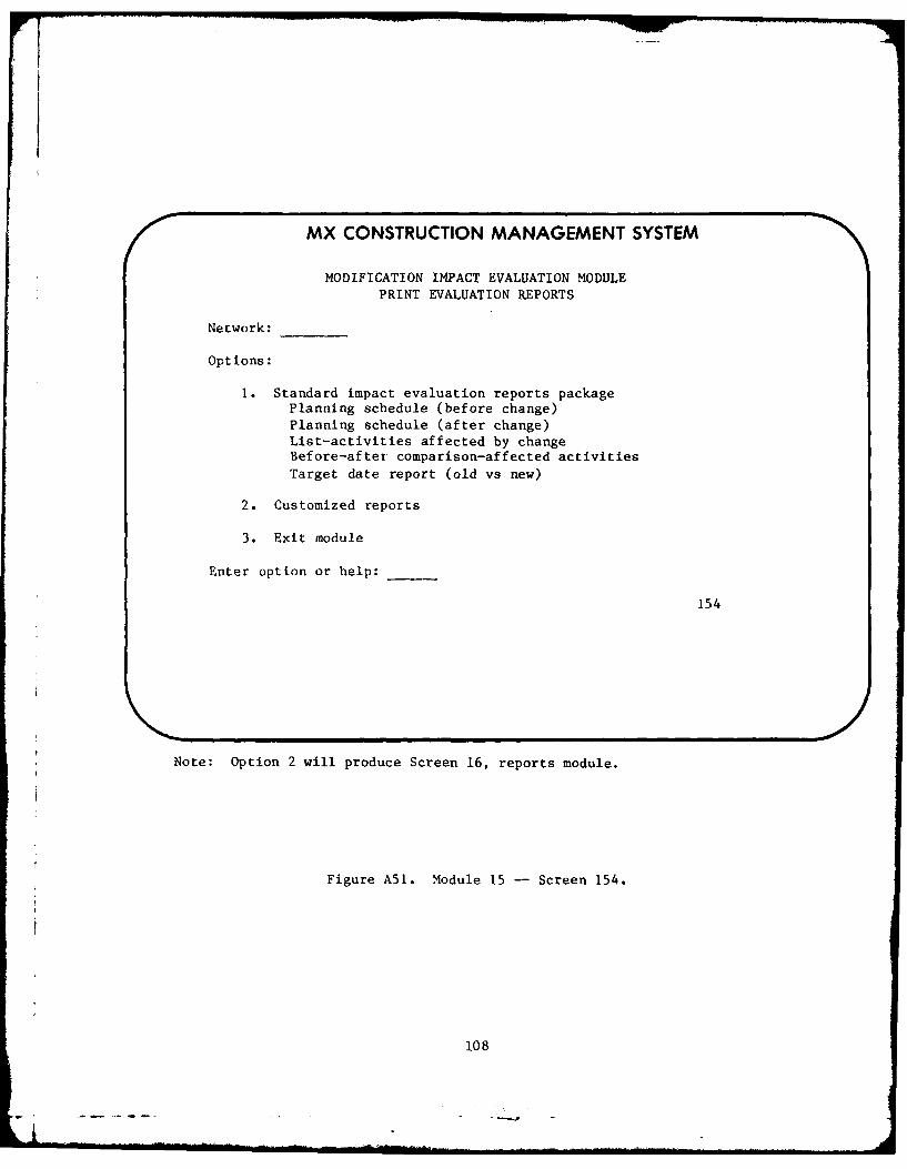
MX CONSTRUCTION MANAGEMENT SYSTEM
MODIFICATION IMPACT EVALUATION MODULE
PRINT EVALUATION REPORTS
Network:
Options:
1. Standard impact evaluation reports packagePlanning schedule (before change)Planning schedule (after change)List-activities affected by changeBefore-after comparison-affected activitiesTarget date report (old vs new)
2. Customized reports
3. Exit module
Enter option or help:
154
Note: Option 2 will produce Screen 16, reports module.
Figure A51. Module 15 -- Screen 154.
108

MX CONSTRUCTION MANAGEMENT SYSTEM
MODIFICATION IMPACT EVALUATION MODULEREMOVE NET FROM WORKING FILE
Options:
1. List working files in this module
2. Delete one or more working files
3. Exit module
Enter option or help:
Delete the following networks:
Enter password:
Network(s) have been deleted (destroyed):
155
Figure A52. Module 15 -- Screen 155.
109

MX CONSTRUCTION MANAGEMENT SYSTEM
MODIFICATION IMPACT EVALUATION MODULECOPY NETWORK
Network:
The above network is to be placed in the "CORRECT/REVISE STORED NETWORK
MODULE" under thL name of network:
Enter password:
PROJECT 2 executing
Transfer has been accomplished
156
After execution return to Screen 15.
Figure A53. Module 15 -- Screen 156.
I
II

MX CONSTRUCTION MANAGEMENT SYSTEM
CORRECT/REVISE STORED NETWORK MODULE
Options:
1. List stored networks2. Copy network to working file
3. Input network changes4. Release revised network to official file5. Exit module
Enter option or help:
Enter network ID:
12
Figure A54. Module 12 -- Screen 12.
111
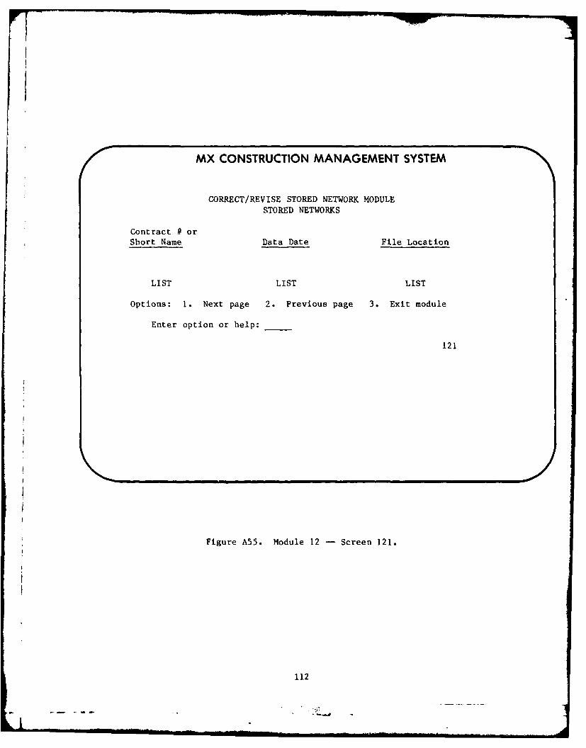
MX CONSTRUCTION MANAGEMENT SYSTEM
CORRECT/REVISE STORED NETWORK MODULESTORED NETWORKS
Contract # orShort Name Data Date File Location
LIST LIST LIST
Options: 1. Next page 2. Previous page 3. Exit module
Enter option or help:
121
Figure A55. Module 12 -- Screen 121.
112
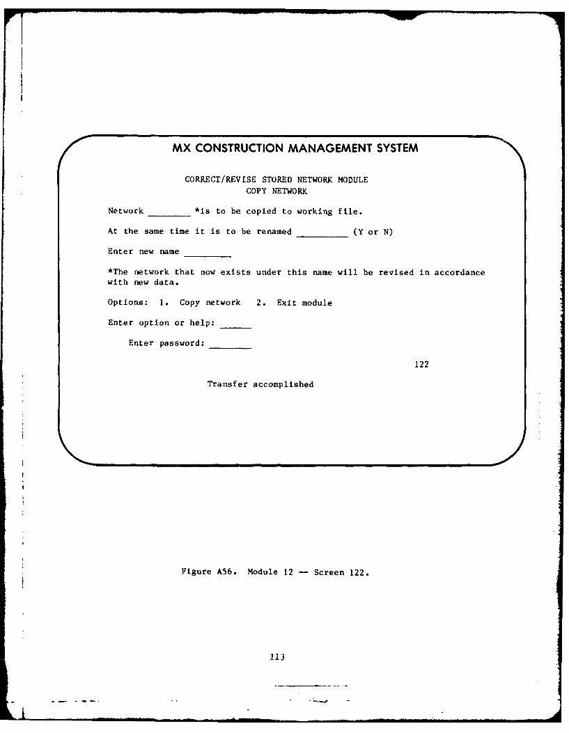
MX CONSTRUCTION MANAGEMENT SYSTEM
CORRECT/REVISE STORED NETWORK MODULECOPY NETWORK
Network *is to be copied to working file.
At the same time it is to be renamed (Y or N)
Enter new name
*The network that now exists under this name will be revised in accordance
with new data.
Options: 1. Copy network 2. Exit module
Enter option or help:
Enter password:
122
Transfer accomplished
Figure A56. Module 12 - Screen 122.
113

MX CONSTRUCTION MANAGEMENT SYSTEM
CORRECT/REVISE STORED NETWORK MODULEINPUT NETWORK CHANGES
Network:
Options:
1. Descriptive information2. Holidays3. Coding data4. Network5. Constraints/relationships6. All of the above in sequence7. Exit module
Enter option or help:
123
Figure A57. Module 12 -- Screen 123.
114
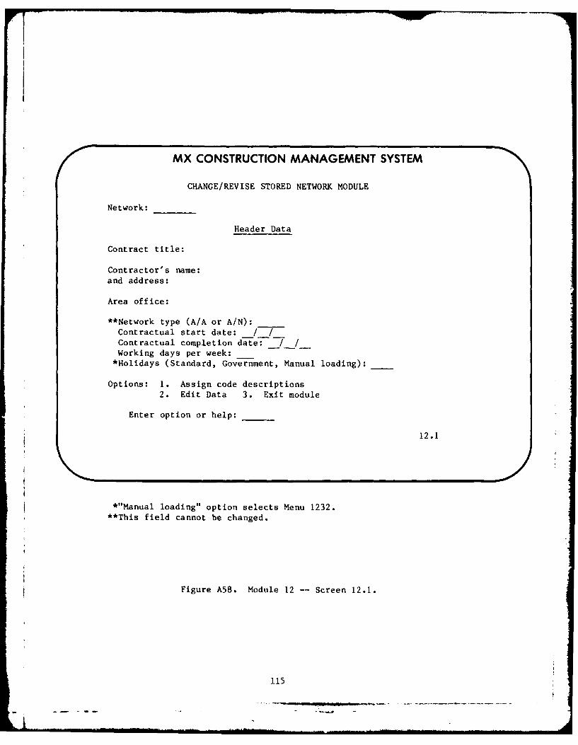
0 MX CONSTRUCTION MANAGEMENT SYSTEM
CHANGE/REVISE STORED NETWORK MODULE
Network:
Header Data
Contract title:
Contractor's name:and address:
Area office:
**Network type (A/A or A/N):
Contractual start date: / /Contractual completion date: 7 /Working days per week:*Holidays (Standard, Government, Manual loading):
Options: 1. Assign code descriptions
2. Edit Data 3. Exit module
Enter option or help:
12.1
*"Manual loading" option selects Menu 1232.**This field cannot be changed.
Figure A58. Module 12 -- Screen 12.1.
115

MX CONSTRUCTION MANAGEMENT SYSTEM
CORRECT/REVISE STORED NETWORK MODULE
Network:
Assign holidays (DDMMMYY):
Options: 1. Assign more holidays2. Return to header menu
3. Assign code descriptions
Enter option or help:
1232
Figure A59. Module 12 - Screen 1232.
116

I
MX CONSTRUCTION MANAGEMENT SYSTEM
CORRECT/REVISE STORED NETWORK MODULE
CODE DESCRIPTION
Network:
Assign code descriptions:
Field (A-B-C): Code: Title:
Code Description
Options: 1. Enter more this field 2. Next field3. Edit data 4. Finished, proceed to enternetwork data 5. Exit module
Enter option or help:
1233
Figure A60. Module 12 - Screen 1233.
117

MX CONSTRUCTION MANAGEMENT SYSTEM
CORRECT/REVISE STORED NETWORK MODULE
Network: ____
Enter activities and events -A/N-
Node: _____Description:_______________________
Duration: Codes: ____Value:________
- REPEAT -
- REPEAT -
- REPEAT -
Options: 1. Enter more 2. Edit data 3. Enter relationships
4. Store network 5. Exit module
Enter option or help:___
1234
Figure A61. Module 12 -- Screen 1234.
118
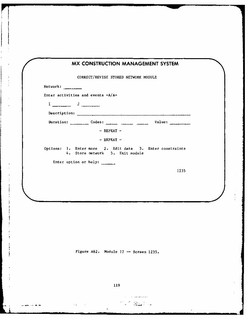
MX CONSTRUCTION MANAGEMENT SYSTEM
CORRECT/REVISE STORED NETWORK MODULE
Network:
Enter activities and events -A/A-
Description:______________________ _____
Duration: _____Codes: _ __ ___ ___ Value:_____
- REPEAT -
- REPEAT -
Options: 1. Enter more 2. Edit data 3. Enter constraints4. Store network 5. Exit module
Enter option or help: ___
1235
Figure A62. Module 12 -Screen 1235.
119

MX CONSTRUCTION MANAGEMENT SYSTEM
CORRECT/REVISE STORED NETWORK MODULE
Network:
Enter activity/event relationships -A/N-
Node: Node:
Relationship (SS-FF-SF-FS): _ Lag: work days
- REPEAT -
- REPEAT -
Options: 1. Enter more 2. Enter constraints
3. Edit data 4. Assign list
5. Store network 6. Exit module
Enter option or help:
1236
Figure A63. Module 12 -- Screen 1236.
120

MX CONSTRUCTION MANAGEMENT SYSTEM
CORRECT/REVISE STORED NETWORK MODULE
Network:
Assign constraints -A/A- and A/N
(Note: Contractual start and finish date have been entered.)
(Enter A/N node number in "I")
I J
Constraint (STArt - FINish): (ON-NET-NLT): Date:
- REPEAT -
- REPEAT -
Options: 1. Enter mode 2. Edit data 3. Assign list4. Store network 5. Exit module
Enter option or help:
1237
Figure A64. Module 12 -- Screen 1237.
121
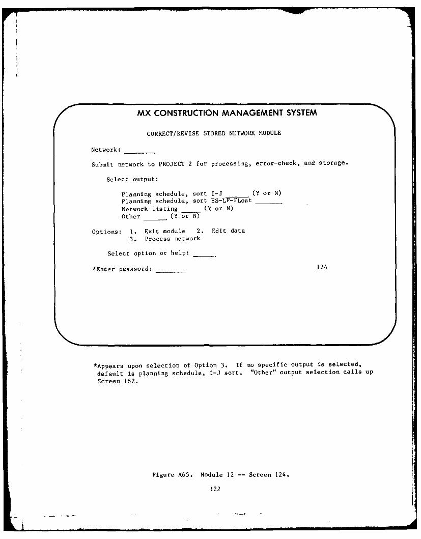
MX CONSTRUCTION MANAGEMENT SYSTEM
CORRECT/REVISE STORED NETWORK MODULE
Network:
Submit network to PROJECT 2 for processing, error-check, and storage.
Select output:
Planning schedule, sort I-J (Y or N)
Planning schedule, sort ES-LF-FLoat
Network listing _ (Y or N)
Other (Y or N)
Options: 1. Exit module 2. Edit data3. Process network
Select option or help:
*Enter password: 124
*Appears upon selection of Option 3. If no specific output is selected,
default is planning schedule, I-J sort. "Other" output selection calls up
Screen 162.
Figure A65. Module 12 -- Screen 124.
122
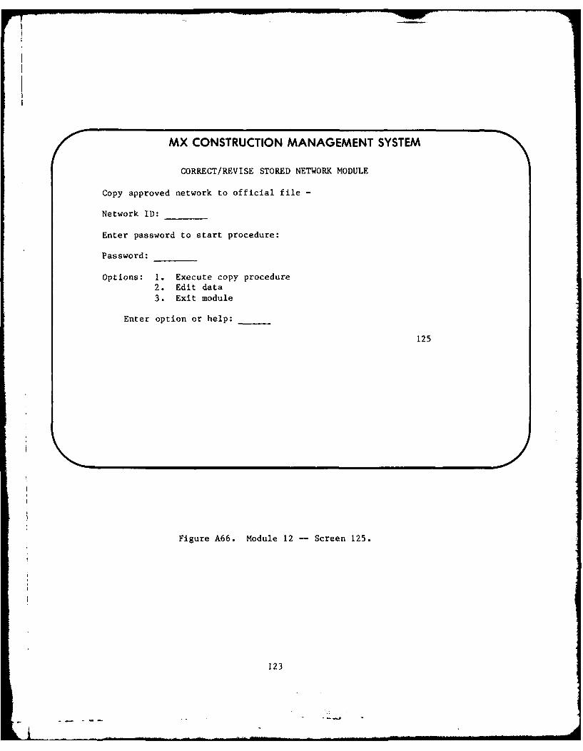
MX CONSTRUCTION MANAGEMENT SYSTEM
CORRECT/REVISE STORED NETWORK MODULE
Copy approved network to official file -
Network ID:
Enter password to start procedure:
Password:
Options: 1. Execute copy procedure2. Edit data
3. Exit module
Enter option or help:
125
Figure A66. Module 12 - Screen 125.
123

MX CONSTRUCTION MANAGEMENT SYSTEM
USER MESSAGE MODULE
Options:
1. List messages2. List users3. Create message4. Edit/remove message
5. Print message6. Exit module
Enter option or help:
Enter password:
18
Figure A67. Module 18 -- Screen 18.
124
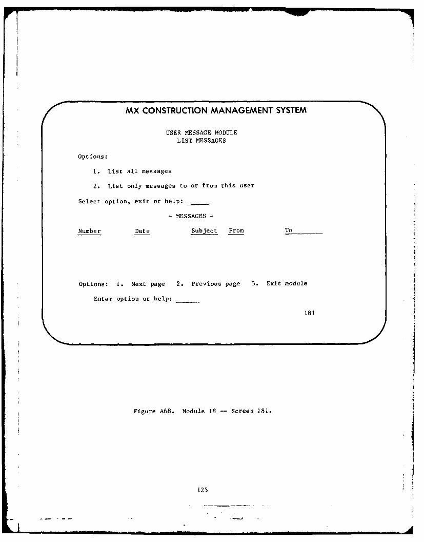
MX CONSTRUCTION MANAGEMENT SYSTEM
USER MESSAGE MODULELIST MESSAGES
Options:
I. List all messages
2. List only messages to or from this user
Select option, exit or help:
- MESSAGES -
Number Date Subject From To
Options: 1. Next page 2. Previous page 3. Exit module
Enter option or help:
181
Figure A68. Module 18 -- Screen 181.
125

MX CONSTRUCTION MANAGEMENT SYSTEM
USER MESSAGE MODULELIST USERS
User No. Name User No. Name
Options: 1. Next page 2. Previous page 3. Exit module
Enter option or help:
182
Figure A69. Module 18 -- Screen 182.
126
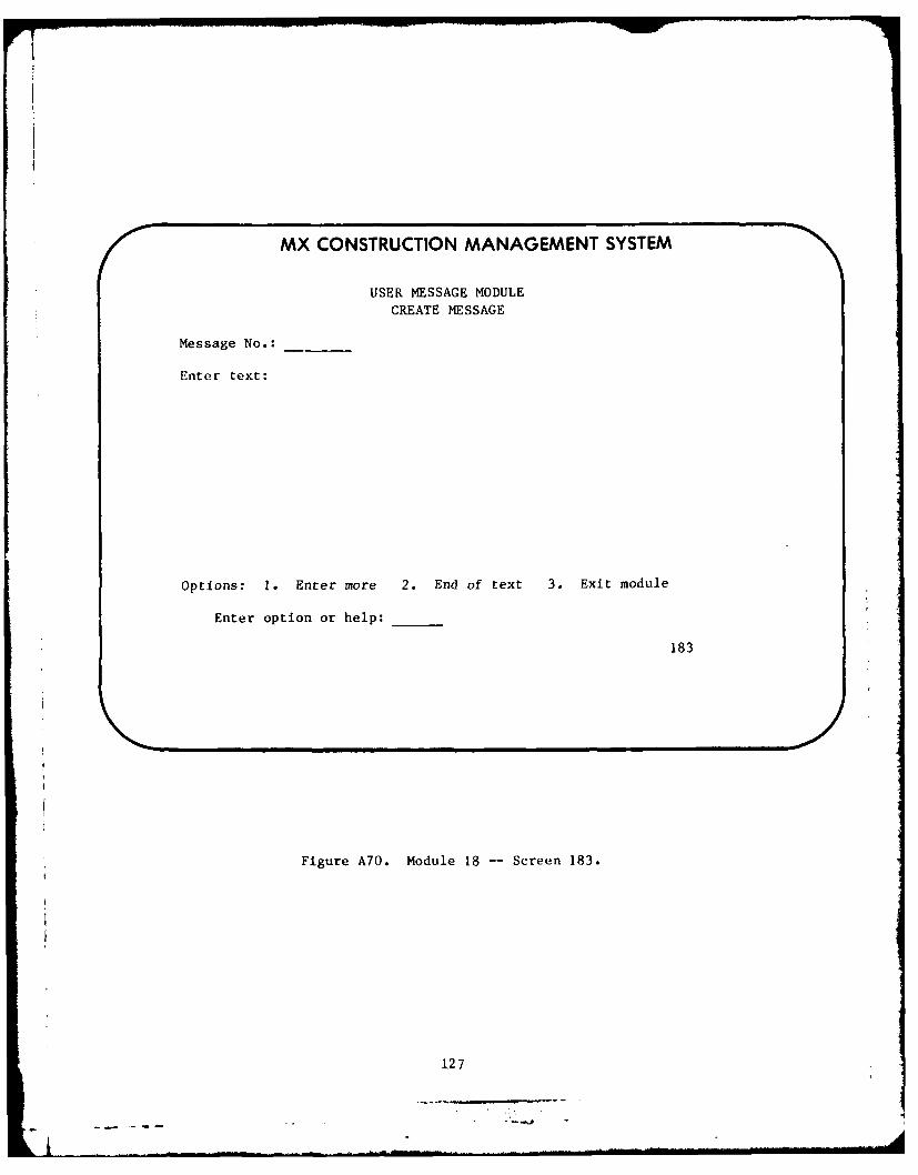
r7
MX CONSTRUCTION MANAGEMENT SYSTEM
USER MESSAGE MODULECREATE MESSAGE
Message No.:
Enter text:
Options: 1. Enter more 2. End of text 3. Exit module
Enter option or help:
183
Figure A70. Module 18 -- Screen 183.
127

MX CONSTRUCTION MANAGEMENT SYSTEM
USER MESSAGE MODULERELEASE MESSAGE
Message No.:
Subject of message:
Enter ID no. of those to receive message
or all: # # # #
if f- F-# #
Options: 1. Release message 2. Exit module
Enter option or help:
Enter password:
1831
Figure A71. Module 18 -- Screen 1831.
128

i
MX CONSTRUCTION MANAGEMENT SYSTEMUSER MESSAGE MODULE
EDIT/REMOVE EXISTING MESSAGE
Message No.:
Existing text:
Options: 1. Edit 2. Next page 3. Previous page
4. Delete message 5. Exit module
Enter option or help:
Enter password:
184
Note: Only the originator can change or remove a message.
Figure A72. Module 18 -- Screen 184.
129............................-

MX CONSTRUCTION MANAGEMENT SYSTEM
USER MESSAGE MODULEPRINT MESSAGE
Message No.: Enter password:
Options: 1. Next page 2. Previous page
3. Hard copy (turn on printer)
Enter option or help:
185
Figure A73. Module 18 -- Screen 185.
130
--. 1---

MX CONSTRUCTION MANAGEMENT SYSTEM
FULL PROJECT/2 ACCESS MODULE
I
Options: 1. Next 2. Previous 3. Up 4. Down 5. Top6. Bottom 7. Insert 8. Modify 9. Delete10. Execute Project 2 II. Erase work area12. Exit module 13. Exit system
Enter option or help: _ _
17
Figure A74. Module 17 screen.
131
---------------------------------
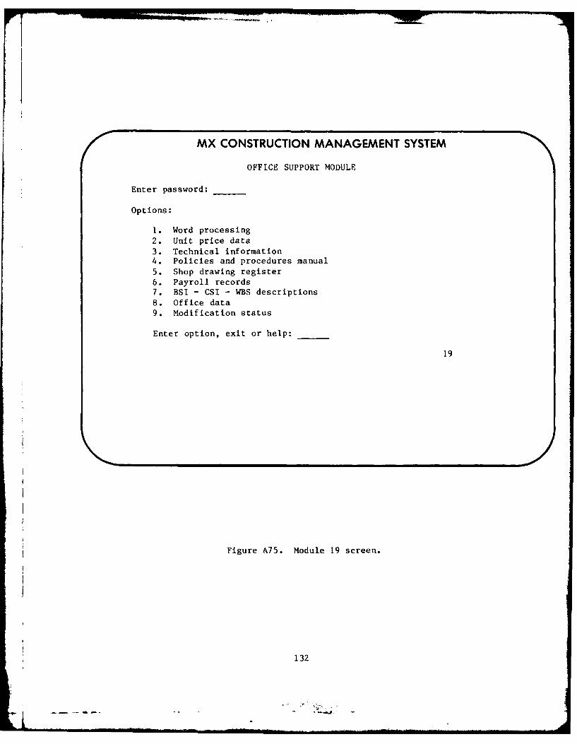
MX CONSTRUCTION MANAGEMENT SYSTEM
OFFICE SUPPORT MODULE
Enter password:
Options:
1. Word processing
2. Unit price data3. Technical information4. Policies and procedures manual5. Shop drawing register6. Payroll records7. BSI - CSI - WBS descriptions8. Office data9. Modification status
Enter option, exit or help:
19
Figure A75. Module 19 screen.
132

APPENDIX B:
EXAMPLE SPECIAL PROVISION
CONTRACTOR PREPARED NETWORK ANALYSIS SYSTEM: The progress chart to beprepared by the Contractor pursuant to GENERAL PROVISIONS clause entitled:PROGRESS CHARTS AND REQUIREMENTS FOR OVERTIME WORK, shall consist of a NetworkAnalysis System (NAS) as described below. In preparing this system, thescheduling of construction is the responsibility of the Contractor. The
requirement for the system is included to assure adequate planning and execu-tion of the work, to assist the Contracting Officer in appraising the reason-ableness of the proposed schedule, to evaluate progress of the work, to makeprogress payments and to make decisions relative to time/cost adjustmentswhich may result from changes in the work.
a. In addition to the schedule described hereinafter, the Contractorshall, within ten (10) calendar days after the Notice to Proceed, submit forapproval a schedule indicating activities and sequence of operations for thefirst ninety (90) calendar days of the construction contract. The scheduleshall consist of not more than one hundred (100) activities and shall beeither an NAS diagram or bar chart. The activities in this preliminaryschedule (as approved) shall be subsequently incorporated into the completeschedule.
b. The Contractor shall within 45 calendar days after receipt of Noticeto Proceed, submit for approval a complete network-based schedule covering theduration of the work. The submittal shall include a NAS diagram plot and amathematical analysis as described below.
(1) The NAS plot diagram shall show the order and interdependence of allactivities and the sequence in which the work is to be accomplished.
(a) The complete NAS schedule shall include, in addition to constructionactivities, the submittal schedules of materials, samples, shop drawings,operation and maintenance manuals, master equipment list, spare parts list,
and other required documents. Also included shall be activities for the pro-curement of all major materials and equipment, including fabrication anddelivery, installation and testing. All activities of the Government, i.e.,GFP, reviews and approvals, etc. that affect the progress and contractrequired milestones and dates for completion of all or parts of the work shallbe shown. Activity numbers shall be selected and assigned so as to permitready identification of each and every activity in the network with itsrespective bid/pay item, as well as to facilitate the generation of both sum-mary and partial (fragmented or "frag") networks. Activity numbering shall beassigned so that preceeding event numbers are smaller numerically than thefollowing event numbers, without duplication. Gap numbering shall be used onthe original network to allow for the addition of subsequent activities and/orlogic changes. The work should be broken down into activities having dura-tions of 20 calendar days or less, with not over 2 percent of the activitiesexceeding these limits.
(2) The Government uses the Project/2 (activity on arrow A/A or activityon node A/N) networking software package, marketed by Project Software and
133
. . .. .. . . . .. . . . . . A . . . . . .- . .. . . . • . . -'.. . . . . . . . . . . . .

Development, Inc., Cambridge, Massachusetts. The Contractor may use any sys-
tem to develop his complete NAS schedule. In addition to furnishing copies ofthe complete NAS schedule, as hereinafter specified, the Contractor shall pro-vide to the Government his schedule in a form compatible with Project/2 dataprotocol. Data may be submitted on punch cards or magnetic tape. Magnetictape specifications are as follows:
(a) Standard IBM labels or none.
(b) 800 to 1600 BBI or 6250 density.
(c) Any blocking is allowed, however, record size must be specified.
(d) Parity may be odd or even.
(e) If multi-file tape, number of files on tape must be specified.
(3) Project/2 data input is in free format English-type language. How-
ever, there are certain restrictions on prescribed conventions. For theseconventions, reference is made to the Project/2 Basic Manual which will beprovided by the Government upon request. This manual also provides data formcompatibility. The following general data is provided:
(a) Activities A/A or A/N -- 32,767 per project (including dummies).
(b) Node length -- A/A 8 digits, A/N 9 digits.
(c) Description length -- 48 characters.
(d) Code fields -- three fields, each 9 digits.
(e) Durations -- maximum 3,000 work periods.
(f) Precedences -- maximum 100,000 (10,000 added at one time).
(g) Resources -- 4,000 maximum per activity, description 36 characters,resource numbered 9 digits (xxxxx.xx).
(h) Project name -- 8 characters.
(4) The following information shall be furnished for each activity:
(a) l-J number (Not to exceed - NTE - 8 digits)
node numbers (NTE 9 digits)
(b) Description (NTE 48 characters).
(c) Duration (calendar days).
(d) Code (see P. (i) below).
134.......
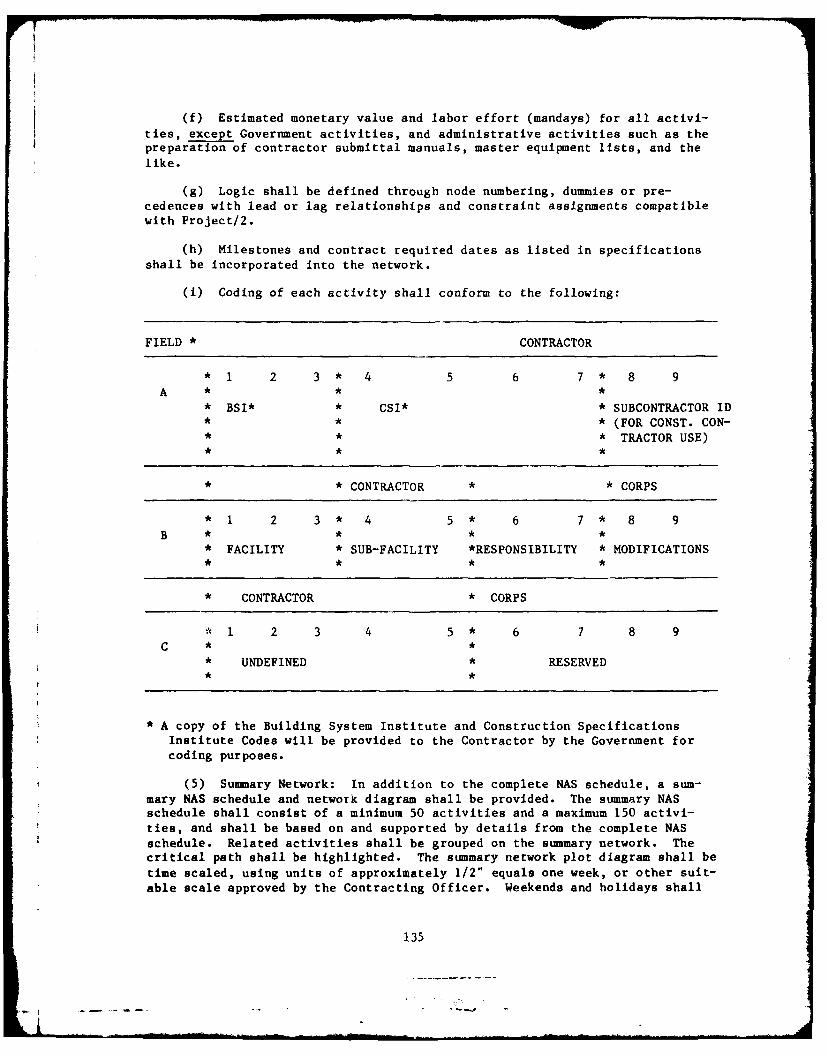
(f) Estimated monetary value and labor effort (mandays) for all activi-
ties, except Government activities, and administrative activities such as thepreparation of contractor submittal manuals, master equipment lists, and the
like.
(g) Logic shall be defined through node numbering, dummies or pre-cedences with lead or lag relationships and constraint assignments compatiblewith Project/2.
(h) Milestones and contract required dates as listed in specifications
shall be incorporated into the network.
(i) Coding of each activity shall conform to the following:
FIELD * CONTRACTOR
*1 2 3* 4 5 6 7* 8 9A * * *
• BSI* * CSI* * SUBCONTRACTOR ID• * * (FOR CONST. CON-* • * TRACTOR USE)
• * CONTRACTOR * * CORPS
•1 2 3* 4 5* 6 7* 8 9
• FACILITY * SUB-FACILITY *RESPONSIBILITY * MODIFICATIONS
• CONTRACTOR * CORPS
*1 2 3 4 5* 6 7 8 9
C **• UNDEFINED * RESERVED
* A copy of the Building System Institute and Construction Specifications
Institute Codes will be provided to the Contractor by the Government forcoding purposes.
(5) Summary Network: In addition to the complete NAS schedule, a sum-mary NAS schedule and network diagram shall be provided. The summary NASschedule shall consist of a minimum 50 activities and a maximum 150 activi-ties, and shall be based on and supported by details from the complete NASschedule. Related activities shall be grouped on the summary network. Thecritical path shall be highlighted. The summary network plot diagram shall betime scaled, using units of approximately 1/2" equals one week, or other suit-able scale approved by the Contracting Officer. Weekends and holidays shall
135

be indicated. Where slack exists, the activities shall be shown at the time
when they are scheduled to be accomplished.
(6) The mathematical analysis of the network shall include a tabulationof each activity contained in the detailed network. As a minimum, the follow-ing information will be required for each activity:
(a) Preceeding and following event numbers.
(b) Activity description and estimated value (cost).
(c) Estimated labor effort for each activity, in mandays.
(d) Estimated duration of activities, in calendar days.
(e) Earliest start date (by calendar date).
(f) Earliest finish date (by calendar date).
(g) Scheduled or actual start date (by calendar date).
(h) Scheduled or actual finish date (by calendar date).
(i) Latest start date (by calendar date).
(j) Latest finish date (by calendar date).
(k) Slack or float.
(1) Responsibility for activity (Prime contractor, subcontractors, sup-pliers, Government, etc.).
(7) Reports and printouts based on the mathematical analysis shall listthe activities in sorts or groups as follows:
(a) By the preceeding event number, from lowest to highest, and then inorder of the following event number.
(b) By the amount of slack or float, then in order of preceeding event
number.
(c) By responsibility, in order of earliest allowable start dates.
(d) In order of earliest allowable start dates, then in order ofpreceeding event numbers, and then in order of succeeding event numbers.
(e) In order of latest allowable start dates, then in order of preceed-ing event numbers, and then in order of succeeding event numbers.
(f) A chart showing the accumulative schedule (standard "S" curve) ofanticipated earnings, in both dollars and percent, based on early, late, andscheduled finish schedules. Actual earnings shall be plotted on the chart asthey occur.
136

Need Scheduled Curve---
(g) Two labor charts -- one showing the accumulative schedules (standard"S" curve) of estimated mandays based on early, late, and scheduled finishschedules, and one showing estimated mandays per month (standard manpower his-tograms) based on early, late, and scheduled finish schedules. Actual man-power expended (in mandays) will be reported on both charts as it occurs.
SES LS
Need Scheduled Curve-
(8) The Contractor shall provide, as a part of all required updates andreports, the rationale for assigning all scheduled and actual dates in thenetwork.
c. The Contractor shall participate in a review and evaluation of theproposed network diagrams and printout analysis with the Contracting Officer.Required revisions shall be resubmitted for approval of the Contracting Off-icer within ten (10) calendar days after the conference. The approved com-plete NAS schedule shall be used by the Contractor for planning, organizingand directing the work, reporting progress, and requesting payment for workaccomplished.
d. The Contractor shall submit on the first and fifteenth of each month,a report of actual construction progress. The report shall consist of anupdating of the mathematical analysis printouts, by sorts listed in paragraphb.(7), together with a narrative description of factors delaying progress, andactions being taken to overcome these delays. Printouts shall include com-pleted and partially completed activities and all remaining activities. Sub-mittal of the network diagrams is not required unless significant changes inthe approved schedule result in a requirement for the submittal of a revisedschedule as outlined in paragraphs (1) and (2) below. Payments, when madepursuant to GENERAL PROVISION clause entitled PAYMENT TO CONTRACTOR, will bebased upon the total value of activities completed and partially completed, asupdated on the Project/2 networking software package in accordance with thisparagraph. If at any time during the life of the project the Contracting Off-icer finds that the monetary amount of an activity is not properly propor-tioned and reasonable, the Contractor shall reapportion the amount prior topayments.
(1) If in the opinion of the Contracting Officer, the approved scheduleno longer accurately reflects the Contractor's real plan for accomplishing theremaining work, or the schedule no longer reflects a viable way of finishingthe work on schedule, the Contractor shall revise the remaining work scheduleto accomplish progress compatible with contract requirements, and shall withinten (10) calendar days of being directed to do so, submit the revised scheduleto the Government for approval. This submittal shall include a revised NASdiagram plot with accompanying mathematical analysis.
137

(2) The approved complete NAS schedule will be used, along with currentjob status data, to determine the time impact of change orders on the work.When the Government issues a request for proposal (RFP), or notice to proceedchange over, any additional time allowed to the contract as required by Gen-eral Provision 3, "CHANGES" and any network changes will be specified by theGovernment. These network changes shall be incorporated into the approvedschedule within ten (10) calendar days after receipt of the Notice to Proceedfor the change order, and the revised schedule submitted in accordance withparagraph (1) above. The Contractor shall prepare his cost proposal based onthe amount of additional time allowed to the contract.
(3) Sheet size of plot diagrams shall be 30" x 42". Each updated copyshall show a date of the latest revision.
(4) Initial submittal and complete revisions shall be furnished in sixcopies.
(5) Periodic submittals shall be furnished in five copies.
138
mOWN"

APPENDILX C:
NOTICE TO CONTRACTOR (USE OF ENG FORM 3938)
1. The attached ENG Form 3938 is used for requesting and submitting pro-
posals on all changes, regardless of amount. This form will also be used forexecuting modifications of less than $25,000 absolute value (total of addi-tions and deletions) under the "Chan--s" clause. Standard Form 30 will beused for executing modifications $Z5,000 and above under the "Changes" clause,and for changes under other clauses.
2. Your proposal should be submitted within calendar days on Sheet 2in Block 11 entitled "Contractor's Proposal." Proposals amounting to $100,000or more in absolute value require the completion and execution of DD Form 633.To expedite action on your proposal, you should submit with your proposal adetailed breakdown of your price. If the space provided is insufficient forthe breakdown, it should be attached.
3. The time element applicable to this change is indicated in theattached ENG Fozm 3938. It is the product of an analysis of the various fac-tors involved, such as current approved construction schedule, current jobstatus, scope of the proposed change, need for the completed facilities, etc.Your proposal shall be based upon the time element specified. Your approvedprogress schedule shall be immediately revised to reflect the changes (if any)itemized in this request for proposal. The network so revised shall be usedto evaluate the time impact of subsequent changes, and progress toward projectcompletion. In the event you consider the time element unreasonable orimpractical you may propose an alternative and accompany it with its relatedcost proposal. (The alternative proposal is in addition to the cost proposalbased on the specified time element, not a substitute for it.)
4. Your cost breakdown should be referenced to new and/or existingactivities in the current approved progress schedule. The cost, if any, asso-ciated with impact on unchanged work shall be itemized and subtotaledseparately from direct costs.
5. The original and all copies of the form shall be signed in BLOCK 11ONLY (on Sheet 2 of 2), dated, and returned promptly to the issuing ResideitOffice. A copy should be retained in your office.
6. After receipt of your itemized proposal at the issuing ResidentOffice, you may expect the following action:
a. Less than $25,000 absolute value.
(1) If your proposal is acceptable, the Contracting Officer or his duly
authorized representative will sign the form in the space provided. The ori-ginal and all copies will be returned to you for signing, in the space pro-
vided, by your representative authorized to execute contract modifications.The signed original and copies should also be returned to the Resident Office.One copy will be retained for your files. This will constitute the notice toproceed and the fully executed modification.
139

(2) If your proposal is not acceptable, you will be notified, and thetime and price will be negotiated. If time is to be negotiated, it shall besettled first and the progress schedule network revised to reflect such agree-ment. Upon agreement on price, the ENG 3938 will be completed by the Con-tracting Officer or his duly authorized representative in accordance with theagreements, and the original and copies will be signed and sent to you forsignature, in the space provided, by your representative authorized to executecontract modifications. The signed original and copies should be returned tothe Resident Office. This will constitute the notice to proceed and the fullyexecuted modification.
b. $25,000 or more:
(1) If your proposal is acceptable, Standard Form 30 will be completed,and signed by the Contracting Officer or his authorized representative. Itwill be sent to you for signing and return to the Resident Office. This willconstitute the notice to proceed and the fully executed modification.
(2) If your proposal is not acceptable, you will be notified, and timeand price will be negotiated as described in Paragraph a(2) above. Uponagreement, Standard Form 30 will be completed and signed by the ContractingOfficer or his authorized representative, and sent to you for signing andreturn to the Resident Office. This will constitute the notice to proceed andthe fully executed modification.
140

Chief f Ei glnsre 8th USA, Korea EN Ch, ist. Din.
ATTN: Tnch 4ueiter ATTN: EAFE 181 96301 ATTN. Pacilities Engine.rATh IlAiN AST L (P) ATIN: EAFE-Y 96358 Arlington ll Station 121 22212ITN: lAiN :13 ATTN: EAFE-iD 96224 Vii lull H anes Station 221a
ArTN M AtZ C ATTN: SAFE 414 96208AIlN. ALN UWqE ATTN: EAPE-H 96271 NOWALT: IIAEN- Llki-t ATTN: EAFE-P 96269 ATTN: Faiitiae EngineerATS. UALLN Co ATTN: EAFE-T 96212 Cemeron Station 22314ATTN: tAE- CM' Port LealB J. Nc'1i1 20319ATTN: UAEN-RP Rocky Mt. ArenaL. SARRM-15 80022 Fort Ny r 22211ATTN: DOAEN-PCATTN. OAEN-PE Area Engineer, AEC-Area Office MTICATTN. DAEN-O ArnoLd Air Force Stotion TN 37399 ATTN: NTiC-OA 20315ATTN: DAEN-MP4-A ATTN: Facilities EngineerATTN: DOAEN-O Western AreA Office, CE OakLend Arey Base 94626ATTN: OAEN-HOC Vanderberg AFB, CA 93437 Bayonne NOT 07002ATTN. DAEN-RD Sunny Point MOT 28461ATTN. OAEN-R 416th Engineer Command 60623ATTN: DAEN-ZC ATTN: Facilities Engineer NARAOCOM, ATTN: OgNA-F 071160ATTN: OAEN-CEATTN: OAEN-ZCI USA Japan (USARJ] TAlCOM. Fec. DiA. 49090ATTN: OAEN-ZCR Ch, FE Din, AJI-FE 96343
Fac Engr lHonshu) 96343 TECOM. ATTN: [RSTE-LA-F 21005FESA, ATTN: Library 22060 Fec Engr lOkinee.) 96331
TRADOCFESA. ATTN: BET Itt 79906 RO6US Combined Forces Command 96301 NO. TRADOC. ATTN: ATEN-FE
ATTN: EUSA-HHCCFC,'Engr ATTN.: Focilities EngineerUS Army Engineer Districts Fort Balnoir 2200ATTN. Librory 00 Military Acedemy 10996 Fort Banning 3190Alaska 99501 ATIN: Facilities Eninenr Fort Bliss 79916Al Bet 09616 ATTN: Dept of Geography & CarLisLe Borrocke 17013Albuquerqu 87103 Computer Science Fort Chaffer 729029ottimore 21203 ATTN: OSCPER/MAEN-A Fort Gic 09640Buffaol 14207 Fort EUstIs 23604Charleston 29402 Engr. Studies Center 20315 Fort Gordon 30905Chicago 60604 ATTN: Library Fort Hen, Icon 11252Detroit 48231 Fort Benjanin Harrison 46216Far Vet 96301 AMMRC, ATTN: 0R609R-WE 02172 Fort Jickson 29207Fort Worth 7102 Fort Kneox 40121Gutvston 77550 USA ARRCOM 61299 Fort Leavenworth 66027itcntingtcn 25721 ATTN.: IRC-MI-l Fort Lee 23U01.ck onoie 32232 ATTN: ORSA-IS Fort McCLllan 36205Jono.. Ah943 Fort Monroe 23651Kansai City 64106 DARCOM - Dir, Inst., & Socs. Fort Rccker 36362LiLtlc leck 72203 ATTN. FaciLities Enginear Fort 2.11 73903LO, Angdts 90053 ARRADCOS 07801 Fort Leonr Wood 65473LocivilLo 40201 Aberdeen Proving Ground 21005MemphiS 38103 Army Maths. and Mechanics Re.. Ltr. TSACO , ATTN: 9TSAS-F 63120Mobile 36626 Corpus Christc Army Aepot L78419NnhvilLe 37202 Harry Diamond Laboratories 20783 USALCNon Orlans 70160 Oug0e Proving Ground 84022 ATTN: Fecilitias EogineerNna York 10007 Jeffarson Proving Ground 47250 Fort Hucchuca 85013NorfoLk 23510 Fort Me'outh 07703 Fort Oitchin 21719noie 691,2 Letcerksnny Army Depot 17PO
Philadelphia 19106 Natick t&0 Lir. 21760 WESTLOMPictsbcrgh 15222 New Cumberland Army Oepot 17270 ATTN: Facilities EngineerPortLand 97208 Pueblo Army Depot 81001 Fort Shelter 96A5lRiydh S903 Rd Riosr Army Depot 75501
HOck tsl,,d 61201 Redoton. AranaL 35800 SHAPE 0055Sacramento 95814 Rock Iland Arsenel 61299 ATTN: Surooob, it
9y Section C.B-OpS
Sen Francisco 94105 Savanna Army Depot 61074 tnfrLstrcctcre Brach, LANOASaanneh 31402 Sharps Army Depot 95331SettLe 99124 Senece Army Depot 14541 HU USEUCOM 09128St. Louis 63101 Tobyhnea Army Depot 1946 ATTN: ECJ 47-LOESt. Paul 55101 TootLe Army Depot 94074Tulsa 7H142 Wet:rolt Arsenol 12199 Fort Belvoir, VA 22060Vicksbrg 39160 Yuma Proving Ground 95364 ATTN: ATZA-DTEEMCello Hal 99362 White Sands Missile Range 88002 ATTN. ATZA-OTE-SWWilmington 29401 ATTN: ATZA-FE
OLA ATTN: DLA-WI 22314 ATTN. Engr. LibraryS Amy En(iinner Divisions ATTN: Canedion Liainon Office (2)ATTN:. Lbrery FORSCOM ATTN: IWR LibraryEurope 0S757 FOR9COM Engineer, ATTN: APEN-FEOuntnvtll :1507 ATTN. Fact i .len Enginenr Cold Regions Hateerch Engineering Lob 03755Loenr hi _inippi Valley 39180 Fort Buohanan O934 ATTN LibraryMiddle test 09039 Fort Bragg 28307Middlr tat iliearl 22601 Fort CaepbeLl 42223 ETL, ATTN: Library 22060Mtsnoari lime, NB101 Pert Caraon 99913Ne England 02154 Fort Devona 01433 Watereys Experiment Station 39190North Atlantic 12007 Fort Drum 13601 ATTN: LibraryNorth Central 60905 FORSCOMNorth Pacific 97208 ATTN: PaciLities Engineer HO. XVIII Airborne Corps end 28307Ohio River 45201 Fort Hed 78544 Pt. BraggPacific Ocean 96858 Fort Indienton Gap 17003 ATTN: AFZA-FE-EESouth Atlantic 30303 Fort train 92311South Pacific 94111 Fort Sam Houston 78234 Chl.ante AFB, IL BIeSSSouthentern 75202 Fort Lewie 99433 3345 CES/GE, Stop 27
Fort McCoy 54656US Army Europe Fort McPh reon 30330 Norton AFB 92409HG, 7th Army Training Command 09114 Fort Deorga 0. Meade 20755 ATTN: AFRCE-iDiiOEEATTN; AETTG-OEM IS Fort Ord 93941
HD 7th Army O0CSEngr. 09403 Fort Potk 71459 NCEL 93041ATTN: AMEN-E" I4) Port Richerdeon 99505 ATTN: Library (Code LOA)
V. Corps 09079 Fort Ri Lay 66442ATTN: AETVOEH I5) Prasidio of Son Francisco 94129 Tyndall AFB, FL 32403
VII. Corpn D9154 Frt Sheridan 60037 AFESC/Enginearing L Service LabATTN: 8A1SEH 5 Fart tart 31313
.lat Support C end 09325 Fort Wainright 98703 Dafensa Technilt Info. Center 22314ATTN. 669W 15) Vancouver Sks. 986680 46N: DOA (121
Oierlin 09742ATTN: AEBA-EN (2) NBC Enoineering Societies Library 10017
Southern European Tek Force 08168 ATTN: HSL-F 78234 Na. York. NYATTN.: 8E2E-ENG (3I ATTN: FasliItI Engineer
Intetaltieon Support Activity 09403 Fitoeleona Army Medical Centar 80240 National Guard Bureau 20310ATTN: AEUS-RP WeLter Radi Army Medical Center 20012 tnateletIon Dieieion
US Government Printin9 Office 22304
Raceiino Saction/Depository Copies (2)
n , - " ' . .. . . . . . ... . . . . T . ... . . .. . . . . . .. .
.. ..z

O'Connor, Hichael J.
MX resident engineer networking guide / by N. J. O'Connor, G. E. Colwell,R. 0. Reynolds. -- Champaign, IL : Construction Engineering Research Laboratory
avaiiable from NTIS, 1982.140 p. (Technical Report ; P-126)
1. MX missile system - managemnt. 2. Network analysis (planning). 3. Manage-ment information systems. I. Colwell, Glenn E. II. Reynolds, Robert D.LMI. Title. IV. Series : Technical report (Construction Engineering ResearchLaboratory (U.S.)) P-126.
-. '-1

DATEI
ILMEI