6942 martin - cheesman dam outlet renovation · cheesman dam cheesmandam ... the owner-furnished...
TRANSCRIPT

9/14/2011
1
Site Location

9/14/2011
2
Cheesman Dam
Cheesman Dam
•Cheesman Dam is a gravity arch masonry dam, faced with granite blocks. First of this type of dam in the United States.
•Dam Height of 221 feet, crest length of 1100 feet (including spillway).
•The dam impounds 79,064 acre feet
History of Cheesman Dam
•Completed in 1905 (1st Dam washed out in Flood of 1900)
•Worlds highest dam at time of construction.
•Outlet Works tunneled through the abutment in 1895
•Auxiliary Outlet Works installed in 1925
•42” Gate Valves Installed behind existing 42” Gate Valves at 80’ (upper) , 60’ (Mid) and 15’ (Low) level’s
•Downstream Valve House installed in 1971
•ASCE National Historic Engineering Landmark designation in 1973

9/14/2011
3
Haymen Fire 2002

9/14/2011
4
Project Need and Purpose
� An Aging Outlet Works dependent and operating on 19th
century technology
� Maintenance of key infrastructure
� A means to contain new sediment loading from Hayman Fire
� Provide upstream control for dam safety
Project Scope� Phase 1 (Completed November 2010)
� Installed 3 new stainless steel slide gates� Installed 3 new trashrack structures� Constructed new control building on the left
abutment� Provided new backup generator
and upgraded the electrical and control equipment throughout the facility
� Phase 2 (Scheduled April 2011 to April 2012)� Remove Larner Johnson Needle Valve� Install new Jet Flow Gate � Decommission all Gate Valves
Cheesman Dam Upstream Control Project
…A Multi-Year – Multi-Phased Project
Purchase Order Purchase Order for Upstreamfor UpstreamSlide Gates Slide Gates
Purchase Purchase Order for Jet Flow Order for Jet Flow
Gate Gate
Phase 1 Phase 1 –– Design, Design, PrePre--QualificationQualification
and Biddingand Bidding
Phase 1 Phase 1 ––Underwater Underwater
Construction (Upstream Construction (Upstream Slide Slide
Gate Installation) Gate Installation) and Phase 2 Designand Phase 2 Design
Phase 2 Phase 2 ––LaborLabor--Intense Intense Demolition/Demolition/
Abandonment and Abandonment and replace Needle Valve replace Needle Valve (1925) with Jet Flow (1925) with Jet Flow
GateGate
20072007
20082008
20092009
20102010
20112011

9/14/2011
5
PHASE I – OVERALL PROJECT PLAN
Outlet Works Orientation
Auxiliary Outlet Works
Primary Outlet WorksLow Level
Mid Level
Low and Mid Level Outlets
Low (15’) Level Outlet
Mid (60’) Level Outlet
Mid (60’) Level Inline 42” Gate Valves
Low (15’) Level Twin Inline 42” Gate Valves
Phase 2Phase 1

9/14/2011
6
Gate Valves at 15’-Level
Inside Water Tunnel at 15’-Level
9/14/2011
7
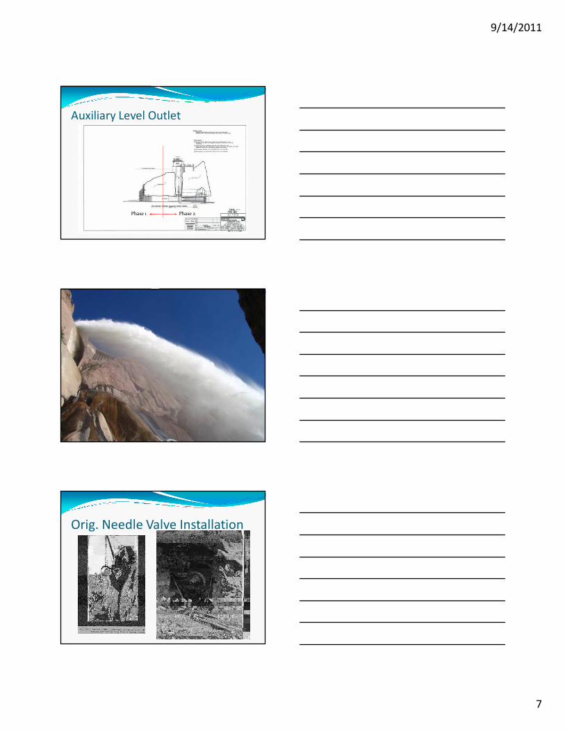
Auxiliary Level Outlet
Phase 2Phase 1
Orig. Needle Valve Installation

9/14/2011
8
New Jet Flow Gate Testing
Drain or Dive?
Cost Benefit Analysis Conclusion: Avoid water storage shortfall (potential watering restriction) risk by paying premium for Construction Diving
� Cost/Benefit Analysis showed a potential savings of ~20-30% if drained and completed in the “dry”.
� Hydrology Study showed a 30% risk of not refilling the reservoir in the following run-off season.
� Not re-filling the reservoir would lead to system wide impacts and possible watering restrictions.
Phase 1 - Contractor Selection� Deep Underwater Construction
requiring Saturation Diving
� Four underwater contractors were pre-qualified
� Two of the prequalified contractors submitted proposals
� Global Diving and Salvage Selected - $12.7M

9/14/2011
9
Saturation Diving Overview
Step 1: Demolish and remove the existing trashracks
Step 3: Drilling, blasting, and tunnel shaping of the tunnel portals and inlet areas.
Steps 4-7: Install guide tracks, floor grout, spool piece, grout and anchor
Step 2: Detailed survey of the area to compare existing underwater conditions to the contract documents
Step 7: Install New Slide Gate
Step 8: Install New Trashrack
Step 9 & 10: Install and Hookup New Hydraulic Lines - Startup Testing and Gate Commissioning
Construction Sequencing
Auxiliary Overview Video
9/14/2011
10
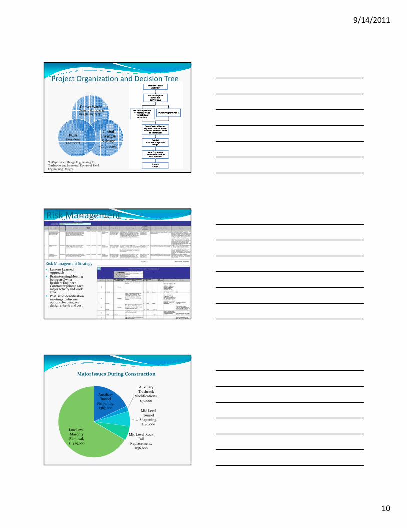
Project Organization and Decision Tree
Denver Water (Owner /Manager & Design Engineer*)
Global Diving & Salvage
(Contractor)
KOA (Resident Engineer)
*URS provided Design Engineering for Trashracks and Structural Review of Field Engineering Designs
Risk Management
Risk Management Strategy
� Lessons Learned Approach
� Brainstorming Meeting between Owner-Resident Engineer-Contractor prior to each major activity and work area
� Post Issue identification meetings to discuss options: focusing on design criteria and cost
Auxiliary Tunnel
Shapening, $383,000
Auxiliary Trashrack
Modifications, $50,000
Mid Level Tunnel
Shapening, $146,000
Mid Level Rock Fall
Replacement, $136,000
Low Level Masonry Removal, $1,425,000
Major Issues During Construction
9/14/2011
11
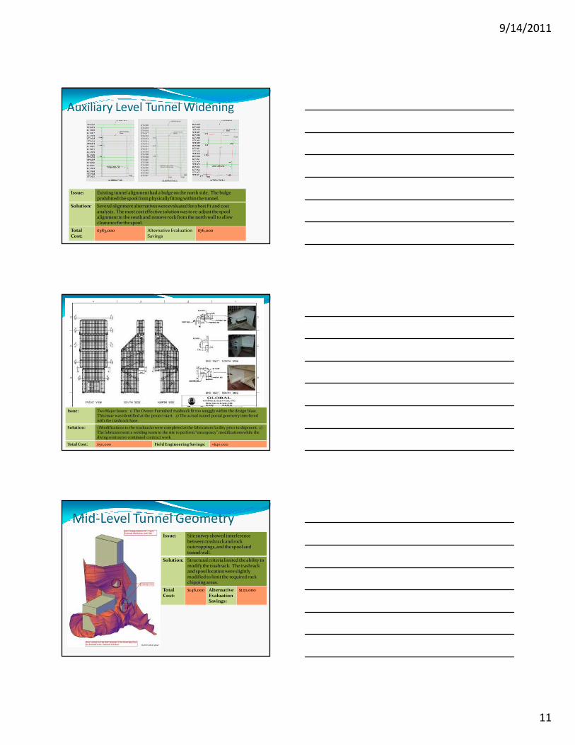
Auxiliary Level Tunnel Widening
Issue: Existing tunnel alignment had a bulge on the north side. The bulge prohibited the spool from physically fitting within the tunnel.
Solution: Several alignmentalternatives were evaluated for a best fit and cost analysis. The most cost effective solution was to re-adjust the spool alignment to the south and remove rock from the north wall to allow clearance for the spool.
Total Cost:
$383,000 Alternative EvaluationSavings
$76,000
Auxiliary Level Trashrack Modifications
Issue: Two Major Issues: 1) The Owner-Furnished trashrack fit too snuggly within the design blast. This issue was identified at the project start. 2) The actual tunnel portal geometry interfered with the trashrack base.
Solution: 1)Modifications to the trashracks were completed at the fabricators facility prior to shipment. 2) The fabricator sent a welding team to the site to perform “emergency” modifications while the diving contractor continued contract work
Total Cost: $50,000 Field Engineering Savings: +$40,000
Mid-Level Tunnel GeometryIssue: Site survey showed interference
between trashrack and rock outcroppings,and the spool and tunnel wall.
Solution: Structural criteria limited the ability to modify the trashrack. The trashrack and spool location were slightly modified to limit the required rock chipping areas.
Total Cost:
$146,000 Alternative EvaluationSavings:
$120,000

9/14/2011
12
Mid Level Rock Fall
Issue: Post blast survey showed large area of rock fall, creating a void area above the spool. The condition did not meet the design criteria for rock cover over the spool piece.
Solution: Create a Mass Concrete wedge to fill the void area. The wedge was designed to replace rock and seepage. Value Engineering iterations increased rebar sizing to reduce rock doweling requirements ($$$), resulting in considerable cost savings.
Total Cost: $136,000 Alternative EvaluationSavings:
$60,000
Historical As-Constructed Drawing
Low Level Masonry Removal
Sector Scan Survey of Low Level
9/14/2011
13
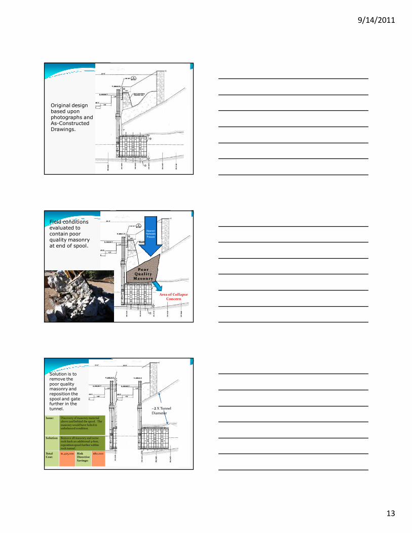
Original design based upon photographs and As-Constructed Drawings.
Field conditions evaluated to contain poor quality masonry at end of spool.
Area of CollapseConcern
Reservoir
Hydrostatic
Pressure
P o o rP o o rQ u a l i t yQ u a l i t y
M a s o n r yM a s o n r y
NewExcavation
Solution is to remove the poor quality masonry and reposition the spool and gate further in the tunnel.
Issue: Discovery of masonry material above and behind the spool. The masonry would have failed in unbalanced condition.
Solution Remove all masonry and some rock back an additional 9-feet, reposition spool further within rock tunnel.
Total Cost:
$1,425,000 Risk Directive Savings:
$80,000
~2 X Tunnel Diameter

9/14/2011
14
Critical Success Factors – Phase 1� Provides robust and redundant
control� New Outlet Works System meets
current Engineering Standards� Extremely low leakage rates � No Lost Production Time or
Standby Fees� Due to Partnering between
Owner-Contractor-Resident Engineer
� Risk Register and Pre-Defined Response Plans facilitated efficient solutions
� Minimal disruption to Denver Water’s operations – Full Reservoir throughout Construction
Performance Testing
� Quality Based Selection Process
� Five contractors prequalified
� Four contractors submitted proposals
� Proposals - $2.9 M to $3.9 M
� Moltz Constructors is Low Proposer at $2.9 M, and scored highest in the technical proposal evaluation
� Currently Working on the Primary Outlet Works Decommissioning
� Scheduled to begin Auxiliary Demo and Jet Flow Gate Installation in November
Phase 2 - Contractor Selection and Progress

9/14/2011
15
Low and Mid Level Outlets
Phase 1 Slide Gates and Trashracks
Abandon old gate valves
Auxiliary Outlet Works - Demolition
Phase 1 Slide Gate and Trashrack
Auxiliary Outlet Works New Jet Flow Gate
Hoover Dam Jet Flow Gate Testing (Also replaced old Needle Valves)

9/14/2011
16
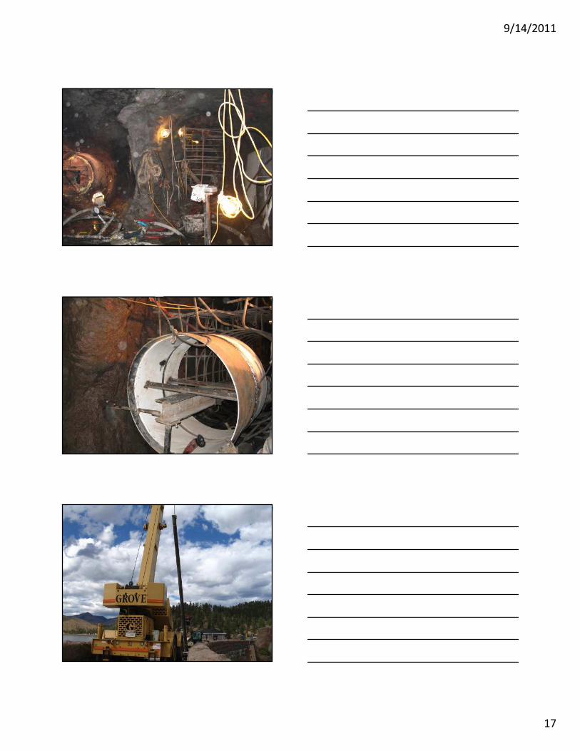
Phase 2 - Progress
9/14/2011
17
9/14/2011
18
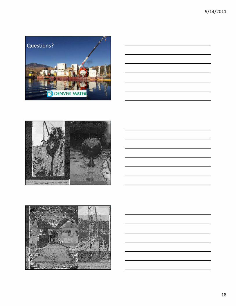
Questions?

9/14/2011
19

9/14/2011
20

9/14/2011
21