68-0039 - direct spark ignition control module...
TRANSCRIPT

Honeywell THE S87 IS A LOW VOLTAGE, SOLID STATE, DIRECT SPARK IGNITION CONTROL MODULE FOR GAS-FIRED FURNACES, BOILERS AND HEATING APPLIANCES. MODELS ARE AVAILABLE WITH OR WITHOUT A PREPURGE TIMER. THE S87 CON- TROLS THE GAS VALVE, MONITORS THE MAIN BURNER FLAME AND GENERATES A HIGH VOLT- AGE FOR SPARK IGNITION.
0 S87A uses a single electrode for spark ignition and flame sensing. Use only with Honeywell gas controls designed for DSI application: V845, V854, VR845, VR854, VR8450 and VR8540.
0 S87B uses a single electrode for spark ignition and flame sensing. Use with any gas control designed for DSI application that is rated at 2.0 A or less. Includes optional alarm circuit for use on system safety lockout.
0 S87C uses separate electrodes for spark ignition and flame sensing. Use only with Honeywell gas controls designed for DSI application: V845, V854, VR845, VR854, VR8450 and VR8540. For direct replacement of S825C. See page 3.
0 S87D uses separate electrodes for spark ignition and flame sensing. Use with any gas control designed for DSI application that is rated at 2.0 A or less. Includes optional alarm circuit. For direct replacement of S825D. See page 3.
•i S87J uses a single electrode for spark ignition and flame sensing. Use with any gas control designed for DSI application that is rated at 2.0 A or less. Includes a 30 second (minimum) delay for use with system prepurge.
0 S87K uses separate electrodes for spark ignition and flame sensing. Use with any gas control designed for DSI application that is rated at 2.0 A or less. Includes a 30 second (minimum) delay for use with system prepurge.
0 External, replaceable fuse protects system trans- former and temperature controller.
0 Automatic system lockout after trial-for-ignition if malfunction exists or main burner flame fails to ignite. All models available with 4, 6, 11, or 21 second (nominal) lockout time.
0 Compact, solid state components for accurate, long-lasting performance.
0 Convenient remote start procedure; after safety shutdown, control module can be reset from the temperature controller.
0 Low voltage control circuit reduces wiring costs.
0 Uses flame rectification principle to prove presence of main burner flame; false flame signal resulting from short to ground results in safety shutdown.
‘-
J.&L FormNumber 68-0039-l REV. 11-84. @Honeywell Inc. 1984

IMPORTANT THE SPECIFICATIONS GIVEN IN THIS PUBLICATION DO NOT INCLUDE NORMAL MANUFACTURING TOLERANCES. THEREFORE, THIS UNIT MAY NOT MATCH THE LISTED SPECIFICATIONS EXACTLY. ALSO, THIS PRODUCT IS TESTED AND CALIBRATED UNDER CLOSELY CONTROLLED CONDITIONS, AND SOME MINOR DIFFERENCES IN PERFORMANCE CAN BE EKPECTED IF THOSE CONDITIONS ARE CHANGED.
The S87 Direct Spark Ignition Control Module con- trols a Direct Spark Ignition (DSI) gas heating system. A combination gas control spark igniter, flame sensor, thermostat or temperature controller, temperature limit controller and 25 Vat transformer complete the DSI system.
The S87 performs the following functions when the thermostat calls for heat.
1. The S87J and K models provide a 30 second prepurge (delay on start-up).
2. All models check for a false flame condition (short to ground). Module will lock out if false flame condition is present. Reset is manually done from the thermostat.
3. Generates 30,000 volts (open circuit) at the spark- igniter stud for direct ignition of the main burner.
4. Opens the main gas control valve. 5. Senses the presence of main burner flame and
discontinues ignition spark. If the burner fails to ignite within the trial-for-ignition period, the S87 goes into safety lockout. Reset is manually done from the thermostat.
8. On a loss of power, the S87 allows the system to shut down safely. Start-up is initiated when power is restored.
7. On a loss of main burner flame, the timed trial-for- ignition is repeated. Safety lockout occurs if flame is not reestablished within the trial-for-ignition period. Reset is manually done from the thermostat.
MODELS: See Table 1.
ELECTRICAL RATINGS: Voltage and Frequency-25 Vat, 60 Hz. Current Rating-O.2 A at 25 Vat. Valve Contacts (S87B,D,J,K)-2.0 A at 25 Vat. Alarm Contacts (S87B,D)-0.5 A at 25 Vat.
THERMOSTAT HEAT ANTICIPATOR SETTING: 0.2 A plus valve current draw.
SAFETY LOCKOUT TIMING: 4, 8, 11,21 set (nominal). Specify when ordering.
FLAME FAILURE REIGNITION TIME: 0.8 set maximum.
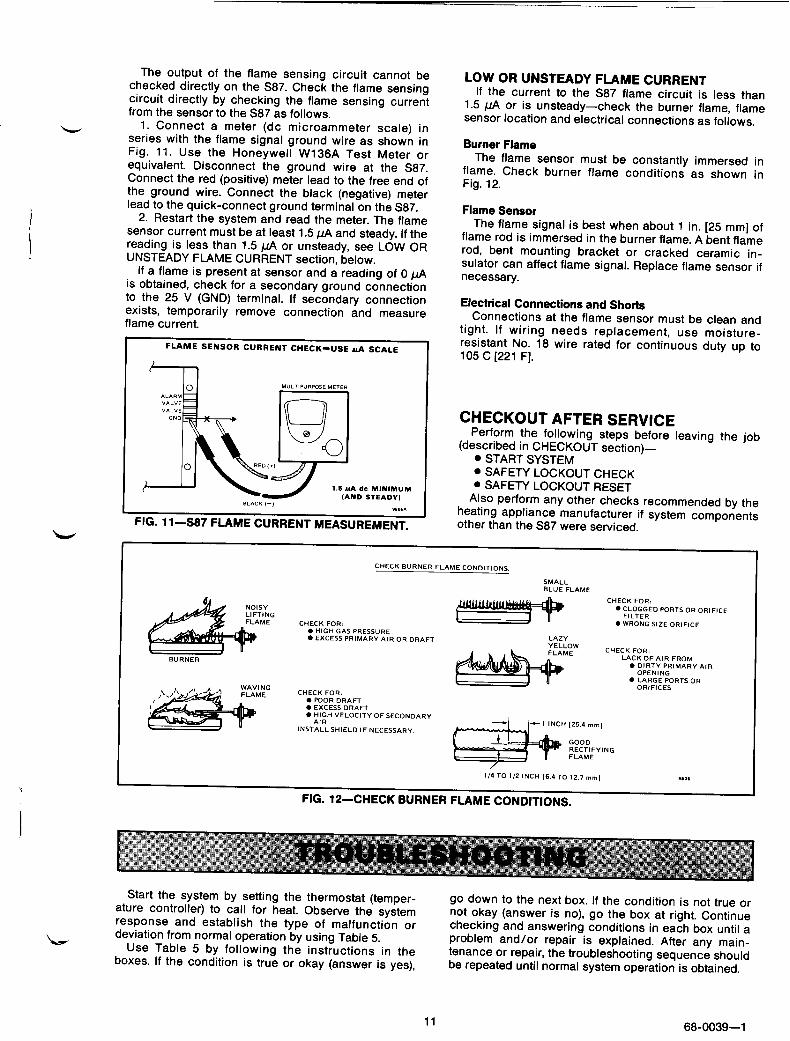
FLAME CURRENT SIGNAL REQUIRED: 1.5 I.~A dc minimum. See Table 1 for recommended flame sensors.
WHEN PURCHASING REPLACEMENT AND MODERNIZATION PRODUCTS FROM YOUR TRADELINE WHOLESALER OR YOUR DISTRIBUTOR, REFER TO THE TRADELINE CATALOG OR PRICE SHEETS FOR COMPLETE ORDERING NUMBER, OR SPECIFY-
1. Order number S87A, B, C, D, J or K. 2. Safety lockout timing (4,8, 11 or 21 seconds). 3. DSI system controls, as required.
a. 25 V, 80 Hz transformer. b. Low voltage thermostat or temperature controller. c. Dual valve combination gas control (for DSI application). d. Spark igniter and flame sensor or combination spark igniter/flame
sensor mounted on single bracket. e. Ignition cable. f. High temperature limit controller and auxiliary controls as required.
IF YOU HAVE ADDITIONAL QUESTIONS, NEED FURTHER INFORMATION, OR WOULD LIKE TO COMMENT ON OUR PRODUCT8 OR SERVICES, PLEASE WRITE OR PHONE:
1. YOUR LOCAL HONEYWELL RESIDENTIAL SALES OFFICE (CHECK WHITE PAGES OF YOUR PHONE DIRECTORY).
2. RESIDENTIAL DIVISION CUSTOMER SERVICE HONEYWELL INC., 1885 DOUGLAS DRIVE NORTH MINNEAPOLIS, MINNESOTA 55422-4388 (812)542-7500
IN CANADA-HONEYWELL LIMITED/HONEYWELL LIMITEE, 740 ELLESMERE ROAD, SCARBOROUGH, ONTARIO MlP 2V9. INTERNATIONAL SALES AND SERVICE OFFICES IN ALL PRINCIPAL CITIES OF THE WORLD.

TABLE 1 - S87 MODELS
MODEL 1 SPARK I FLAME I
aValve used must be designed for DSI application.
bThese models have an alarm circuit.
‘Single electrode for spark ignition and flame sensing.
dS87C can be used for direct field replacement of S825AC. S87D can be used for direct field replacement of S825A-D.
eSeparate spark igniter and flame sensor mounted on a common bracket.
flncludes a 30 second (minimum) prepurge timer.
SPARK GENERATOR VOLTAGE: 30,000 V open circuit. See Table 1 for spark igniter.
IGNITION CABLE: Type-See Table 2 below. Maximum length, 3 ft.
[0.9 m]. Connectors-snap-spring, l/4 in. [8.4 mm] diameter.
TABLE 2--RECOMMENDED IGNITION CABLE
RMS VOLTAGE
/ TEMRPAETq;URE
CABLE TYPE RATING F C UL Style 3217 10,000 302 150
UL Style 3257 10,000 482 250
MOUNTING: Mounts in any position. See Fig. 1. DIMENSIONS: See Fig. 1. AMBIENT TEMPERATURE RATING: Minus 40 F to plus
175 F [minus 40 C to plus 79 C]. RELATIVE HUMIDITY RATING: 5 to 95 percent at 90 F
[32 C]. PREPURGE TIMING (S87J,K): 30 seconds, minimum;
45 seconds, maximum. WIRING CONNECTIONS: l/4 in. [8.4 mm] male, quick-
connect terminals for system component connec- tions and l/4 in. [8.4 mm] diameter stud base for ignition cable.
UNDERWRITERS LABORATORIES INC. LISTED: File No. MH11790.
AMERICAN GAS ASSOCIATION CERTIFIED: No. 20-148.
CANADIAN GAS ASSOCIATION CERTIFIED: No. 1029-ABI-5037A.
REPLACEMENT PART: 3 A fuse.
FIG. 1-DIMENSIONS OF S87 IN in. [mm IN BRACKETS].
WHEN INSTALLING THIS CONTROL MODULE.. . 1. Read these instructions carefully. Failure to follow
them could damage the product or cause a hazardous condition.
application.
3. The installer must be a trained, experienced service technician.
- 2. Check the ratings given in the instructions and on the product to make sure it is suitable for your
4. After installation is complete, check out system operation.
3 68-0039-l

P
1.
2.
Disconnect power supply before wiring the S87 to prevent electrical shock or equipment damage. If a new gas control is to be installed, turn off gas supply before starting installation. Be sure to conduct a Gas Leak Test after the gas control is installed (follow manufacturer’s in- structions or see instructions on page 8).
IMPORTANT If this is a replacement application, follow the appliance manufacturer’s instructions if available. The manufacturer usually provides wiring dia- grams, start-up and checkout instructions and service procedures for their system. If the manu- facturer’s instructions are not available, the infor- mation below may be used as a general guide.
MOUNT THE S87 CONTROL MODULE 7. Select a location within 3 ft [0.9 m] of the burner that
will permit a direct cable route to the spark igniter or igniter/sensor. Ready access to the S87 terminals is necessary for wiring and servicing. Do not exceed the ambient temperature rating given in the SPECIFI- CATIONS section.
The S87 may be mounted in any position. See Fig. 1 for mounting dimensions. Use No. 8-32 machine screws or No. 8 sheetmetal screws 1 inch long for fastening. Fasten securely.
MOUNT THE AUXILIARY CONTROLS Mount the spark igniter, flame sensor, thermostat,
transformer, gas control and any other auxiliary con- trols according to the manufacturer’s instructions.
NOTE: S876, D, and K installations require a trans- former rated to handle both the S87 current and gas valve current. Table 3 shows the transformer rating necessary for various valves. S87A, C and J in- stallations require a transformer with a rating of at least 30 VA.
TABLE 3-TRANSFORMER RATINGS FOR S87B, D, K AND DUAL VALVE COMBINATION GAS CONTROL
MINIMUM TOTAL VA VALVE S87B,D,K
RATING CURRENT CURRENT (25 V transformer) (In amperes) (in amperes)
20 30 40
up to - - . 0.8 0.2 0.8 to 1 .O 0.2 1.0 to 1.4 0.2
55 ( 1.4t02.0 0.2
GENERAL PRECAUTIONS - 1.
2.
3.
4.
5.
8.
Check the wiring diagram furnished by the heating appliance manufacturer, if available, for circuits differing from the ones shown. Carefully follow any special instructions affect- ing the general procedures outlined below. All wiring must comply with applicable elec- trical codes and ordinances. Disconnect the power supply before wiring to prevent electrical shock or equipment damage. If installing a separate Q354A flame sensor, the sensor leadwire should be kept as short as possible and should not be allowed to rest against grounded metal surfaces. A common ground is required for the S87, the spark igniter and the main burner. The 25 V (GND) terminal internally grounds one side of the transformer. Any auxiliary controls or limits must not be in the grounded leg. Ignition cable should not touch any metal surface or current-carrying wires. It must not be more than 3 ft [0.9 m] long. Do not short valve terminals as this may burn out the temperature controller, the transformer or the S87 fuse.
WIRE THE S87 CONTROL MODULE 1. Connect system components to the S87 terminals
as shown in the wiring diagrams, Figs. 2-9. Refer to the heating appliance manufacturer’s instructions for wiring any other auxiliary controls.
NOTE: Use only recommended ignition cable (see Table 2) to connect the S87 with the spark igniter. Cable must not run in continuous contact with a metal surface or spark voltage will be greatly re- duced; use ceramic standoff brackets if necessary. Cable length must not exceed 3 ft [0.9 m].
2. Adjust thermostat heat anticipator to match system current draw. The current draw equals the total current required for the S87 (0.2 A) plus the gas valve and all other 24 V control loads (vent dampers, prepurge relays, etc.). Gas valve must be designed for DSI application.
GROUNDING S87, SPARK IGNITER AND MAIN BURNER
For the system to operate properly, spark igniter, flame sensor and S87 control module must share a common ground with the main burner. Use thermo- plastic insulated wire with a minimum rating of 105 C [221 F] for the ground wire; asbestos insulation is not acceptable. If necessary, use a shield to protect the wire from radiant heat generated by the burner. Connect the ground wire as follows.
1. Fit one end of the ground wire with a female 1 f4 in. quick-connect terminal and connect it to the male quick-connect GND (BURNER) terminal on the S87 control module.
2. Strip the other end of the wire and fasten it under the igniter bracket mounting screw. If necessary, use a shield to protect the ground wire from radiant heat. The burner serves as the common grounding area.
NOTE: It is not necessary that the burner is “earth” grounded.
4

IG. 2-S87A IN TYPICAL HOOKUP FOR DIRECT SPARK IGNITION HEATING SYSTEM. SEE FIG. 13 FOR SYSTEM SCHEMATIC DIAGRAM.
IG. 3-S87B IN TYPICAL HOOKUP FOR DIRECT SPARK IGNITION HEATING SYSTEM. SEE FIG. 14 FOR SYSTEM SCHEMATIC DIAGRAM.
2 2 ALTERNATE LlMlT CONTROLLER LOCATION
3 MAXIMUM IGNITER-SENSCIR CABLE LENGTH: 3 1,. [Il.9 m,m LESS.
4 FACTORY4NSTALLED WIRES. DO NOT REMOVE 2 3 A REPLACEABLE FVSE. 9(112E
FIG. 4-S87C IN TYPICAL HOOKUP FOR DIRECT SPARK IGNITION HEATING SYSTEM. SEE FIG. 15 FOR SYSTEM SCHEMATIC DIAGRAM.
II I I I ALARM. IF “SE0
r---1 0 0
2 ALTERNATE LIMIT CONTROLLER LclCATlON
8
3 MAXIMUM IGNITER-SENSOR CABLE LENGTH: 4‘1. p3.9 rn]OR LESS
4 3 A REPLACEABLE FUSE. 9814C
IG. 5-S87D IN TYPICAL HOOKUP FOR DIRECT SPARK IGNITION HEATING SYSTEM. SEE FIG. 16 FOR SYSTEM SCHEMATIC DIAGRAM.
5 68-0039-l

BVRNER
IGNITER-SENSOR AND BURNERGROUND
n 1 POWER SUPPLY. PROVIDE DISCONNECT MEANS AND OVERLOAD PROTECTION AS REPUIRED. 2 2 ALTERNATE LIMIT CONTROLLER LOCATION.
3 MAXlMUM IGNITER-SENSOR CABLE LENGTH 3 ft. [‘X9 ml OR LESS.
n 4 3 A REPLACEABLE FUSE. 1 I .391*
-- -.--__ FIG. 6-S67J IN TYPICAL HOOKUP FOR DlRtCl i’
SPARK IGNITION HEATING SYSTEM WITH PREPURGE BLOWER CONNECTION. SEE FIG. 17 FOR SYSTEM SCHEMATIC.
LlMlT CONTROLLER
::0T)_n
TEMPERATURE TRANSFORMER L2+
CONTROLLER
COMEluSTION AIR BLOWER
COMBUSTlDN AIR
RELAY
0 I 1
l-
ANY COMBlNATlON GAS CONTROL
IGNITER AND BURNER GROUND
n I POWER SUPPLY. PRO”,DE DISCONNECT MEANS AND OVERLOAD PROTECTION AS REQUIRED.
ALTERNATE LlMlT CONTROLLER LOCATION.
MAXIMUM IGNITER-SENSOR CABLE LENGTH: 3 ‘t. 10.4 m,OR LESS.
3 A REPLACEABLE FUSE. 1 I ,391A
7-S67K IN TYPICAL HOOKUP FOR DIRECT SPARK IGNITION HEATING SYSTEM WITH PREPURGE BLOWER CONNECTION. SEE FIG. 16 FOR SYSTEM SCHEMATIC.
6

FAN CONTROL u L
c H
FAN MOTOR
1 n POWER SUPPLY. PROVlDE DISCONNECT MEANS AND OVERLOAD PROTECTION AS REQUIRED.
n 2 OPTIONAL LIMIT CONTROLLER LOCATION. 9815D
FIG. 8-S87 IN TYPICAL HEAT-COOL APPLICATION WITH DIRECT SPARK IGNITION HEATING SYSTEM.
UMlT
n 1 POWER SUPPLY. PROVIDE DISCONNECT MEANS AND OVERLOAD PROTECTION AS REQUIRED.
25” (GND) A n 2 ALTERNATE LIMIT CONTROLLER LOCATION. DUAL VALVE.
3 FACTORYdNSTALLED WIRES. DO NOT REMOVE.
GAS CONTROL n
ALARM TERMINAL PROVIDED ON 5878 AND D ONLY. 9B10B
FOR BURNER HOOKUP. SEE HOOKUP DIAGRAMS FOR 587 MODEL.
..-.__. ..-_-.-.a _.-_---- FIG. g-S87 IN TYPICAL TWO-STAGE DIRECT SPARK IGh I ION PEA I INCi srs 1 EM.
7 66-0039-l

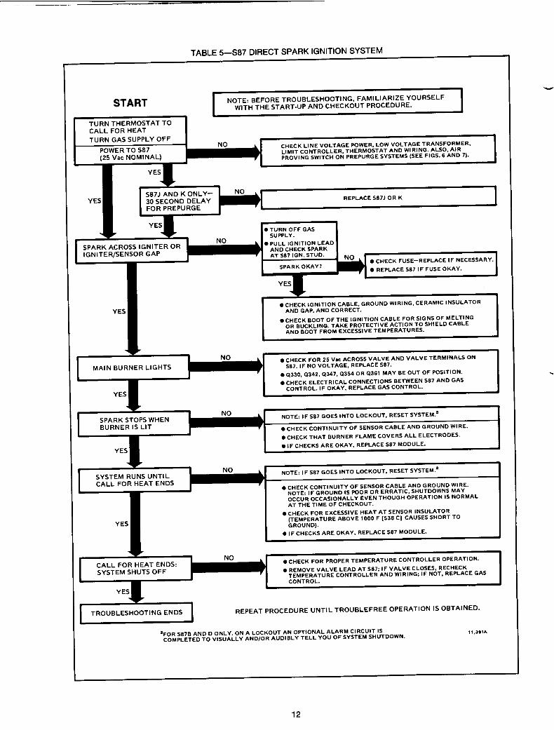
The following start-up and checkout procedures are basic to all S87 control modules. If this is a replacement application, refer to the specific instructions provided by the heating appliance manufacturer (if available). Also, since the auxiliary controls used on any DSI system may differ, refer to the manufacturer’s instruc- tions for checkout and start-up procedures for other system components.
NOTE: If one of the system components fail, the S87 will either not operate or it will go into safety lockout (depending on the type of failure). If the system does not perform as outlined in START SYSTEM and CHECK SAFETY LOCKOUT steps below, refer to the SERVICE section to determine the cause.
GAS LEAK TEST TABLE 4-S87 LOCKOUT TIMES
If the gas control has been replaced as part of the S87 installation, perform the following test for gas leaks. SPECIFIED S87
LOCKOUT TIME (stamped on S87
SAFETY LOCKOUT TIME SHOULD
//////////////N////////Y//
THE GAS LEAK TEST MUST BE PERFORMED TO AVOID POSSIBLE EXPLOSION OR FIRE.
With the main burner in operation, paint the pipe joints and valve gasket lines with a rich soap and water solution. Bubbles indicate a gas leak. To stop leak, tighten joints and screws or replace the gasket. Never use a flame to check for gas leaks.
START SYSTEM 1. Turn on the power and the gas supply. 2. Set thermostat to call for heat and watch for spark
at the igniter. (S87J and K models have a 30 second delay on start-up for prepurge.) Time the length of the spark operation; it must be within the lockout timing period (see Table 4).
3. Check that the system starts as follows: Spark turns on, gas valve opens at once, and burner ignites after gas reaches the main burner. Once burner flame is established, spark igniter cuts off.
The S87 control module performs the following basic functions:
Provides a 30 second (minimum) system prepurge- S87J and K models only.
Supplies power to the electronic pulse-generator circuit for the spark igniter (30,000 volts, open circuit).
Allows up to 35 seconds (maximum) for ignition before system safety lockout occurs (see Table 4).
Senses the burner flame for safe lighting.
Shuts off spark after burner is lit.
NOTE: If the gas control has been replaced or serviced, lightoff may not be satisfactory until air has been purged from the gas line or the gas input and combustion air have been adjusted (see manufac- turer’s instructions).
CHECK SAFETY LOCKOUT 1. With the system power off and the thermostat set
to call for heat, manually shut off the gas supply. 2. Turn power on to energize the S87 and begin
spark ignition, immediately start timing. 3. Determine the number of seconds to safety
lockout (spark cutoff). It should not exceed the time shown in Table 4.
control module) 4.0 sec.
NOT EXCEED-
! 5.0 sec. 6.0 sec. 7.0 sec.
11 .O sec. 15.0 sec. 21 .O sec. 35.0 sec.
4. After spark cutoff, manually reopen gas supply cock. No gas should flow to the main burner.
5. Reset system as described below.
RESET S87 AFTER SAFETY LOCKOUT If the control goes into safety lockout, it will remain
locked out until the system is reset. To reset the system, adjust the thermostat setting
below room temperature, wait 30 seconds, and move the thermostat setting up to call for heat. Normal ignition should occur as described in START SYSTEM, above.
CHECKOUT Start system and observe operation through at least
one complete cycle to make certain all controls are operating safely.
The S87 is powered by a 25 V transformer and activated when the thermostat calls for heat. Operation is as follows (refer to Fig. 10).
On every call for heat (system start), the S87J and K will delay start-up to provide a 30 second (minimum) system prepurge. After 30 seconds, the operation is the same as all other S87 models.
When the S87 is activated by a thermostat call for heat, an internal transformer provides power to the electronic generator circuit for spark ignition and the safety lockout timing begins. At the same time, the S87 opens the gas control’s main valves which allows gas to flow to the main burner.
8

. . The S87 will keep the gas control main valve open as
Power is supplied to the spark generator until: l the main burner lights and flame sensor current
reaches 1.5 @, or l the safety lockout timing period ends.
If the main burner lights, a flame sensing circuit is completed through the flame to the burner head to ground. This current flow sets the safety lockout timer to the reset (normal) condition and interrupts the spark ignition circuit. Should the current flow be interrupted; i.e., flame-out condition, the trial-for-ignition begins again.
flame sensing circuit. If, however, the safety lockout timing period ends before the main burner lights or the flame sensor establishes enough current, the system will go into safety lockout.
When the system goes into safety lockout, power to the spark generator is interrupted, the gas control circuit is interrupted and the alarm circuit (S87B and D only) is completed. The system will stay locked out until it is reset by moving the thermostat set point below room temperature, no call for heat, for 30 seconds. Then, re-energize the system by moving the thermostat set point 5 F [3 C] above room temperature. long as there is a call for heat and current through the
START
I THERMOSTAT CALLS FOR HEAT
I
PREPURGE -S87J.K ONLY
TRIAL FOR IGNITION
MAIN BURNER OPERATION
END
I I PREPURGE--S87J,K ONLY
COMBUSTION AIR BLOWER STARTS.
I
I I COMBUSTION AIR CHECK I
POWER INTERRUPTION ALL S87’S
SYSTEM SHUTS OFF, RESTARTS WHEN POWER IS RESTORED.
POWER RESTORED
I 587 STARTS TRIAL-FOR-IGNITION.
SPARK GENERATOR POWERED IF NO SPARK, S87 GOES INTO LOCKOUT AFTER TIMING PERIOD. 5878 AND D ALARM CIRCUIT IS
MAIN VALVE OPERATORS OPEN. ACTIVATED. SYSTEM MUST BE RESET.
I IF FLAME CURRENT SENSED
I SPARK GENERATOR IS SHUT OFF. LOCKOUT TIMER IS RESET.
IF FLAME CURRENT NOT SENSED I
587 GOES INTO LOCKOUT AFTER TIMING PERIOD. 5878 AND D ALARM CIRCUIT IS ACTIVATED. SYSTEM MUST BE RESET.
I
MAIN BURNER OPERATION LOSS OF FLAME
SPARK GENERATOR IS POWERED.
587 MONITORS BURNER FLAME 587 GOES INTO LOCKOUT AFTER TIMING
CURRENT. PERIOD. 5878 AND D ALARM CIRCUIT IS ACTIVATED. SYSTEM MUST BE RESET.
I I 1 J
. l
TEMPERATURE CONTROLLER SATISFIED
POWER TO SE7 IS INTERRUPTED. VALVES CLOSE. MAIN BURNERS ARE OFF.
1 I.JSPA
FIG. lO-NORMAL SYSTEM SEQUENCE OF OPERATION.
9 68-0039-l

IMPORTANT 1.
2.
3.
4.
5.
6.
Only persons trained and experienced in DSI systems should service this equipment. If a condition exists that causes the S87 control module to go into safety lockout, meter readings must be taken quickly after restart- within trial-for-ignition period. Always de-energize the system for at least 30 seconds before recycling for further tests. Always turn off gas supply before performing ignition checks. S87 control module cannot be repaired. If the troubleshooting procedure indicates a malfunc- tion in the S87, it must be replaced. The following service procedures are for the S87 and basic DSI systems. On all installa- tions, refer to the appliance manufacturer’s service instructions.
PRELIMINARY CHECK The following checks should be made before trouble-
shooting the system. 1. Check for power to the heating appliance and the
S87. Voltage to S87 should be between 20.5 and 28.5 Vat.
2. Check fuse on S87 control module and replace if blown.
3. Make certain that the manual shutoff valve in the supply line and the gas cock knob on the combination gas control valve are open.
4. Make certain that all wiring connections are clean and tight.
5. Make certain the S87 is not in safety lockout. De- energize the system by moving the thermostat set point below room temperature. Wait at least 30 seconds and reenergize the system by moving the thermostat set point 5 F [3 C] above room temperature. Return set point to normal temperature setting.
6. Check ceramic insulator on flame sensor, spark igniter or igniter/sensor. A cracked insulator will allow current to leak to ground. Replace device if insulator is cracked.
7. Check the flame sensor and its mounting bracket Correct the position if bent out of shape.
8. Review the S87 normal sequence of operation. See START SYSTEM section.
S87 COMPONENT CHECKS SPARK IGNITION CIRCUIT
The step-up transformer in the S87 provides spark ignition at 30,000 volts (open circuit). To check the spark ignition circuit, proceed as follows.
1. Shut off gas supply to the gas control. 2. Disconnect the ignition cable at the S87 stud
terminal to isolate the circuit from the spark igniter or igniter/sensor. Prepare a short jumper lead, using heavily insulated wire such as ignition cable.
In the next step, DO NOT allow fingers to touch either the stripped end of the jumper or the stud
1 electrical shock can result 1 ’ ’ termtnal. Thus IS a very hrgh voltage clrcurt and
3. Perform this test immediately upon energizing the system - before the S87 goes into safety lockout and interrupts the spark circuit. Touch one end of the jumper firmly to the S87 GND terminal. (DO NOT remove the existing ground lead.) Slowly move the other end of the jumper wire toward the stud terminal on the S87 to establish a spark. Pull the wire away from the stud and note the length of gap at which spark discontinues.
4. A spark length of i/8 inch [3 mm] or more indicates satisfactory voltage output. If no arc can be established or the maximum spark is less than l/8 in. [3 mm], and power to the S87 input terminals was proved, replace the S87.
IGNITION CABLE, Check the electrical continuity of the ignition cable
and make certain the cable is not in contact with metal surfaces. The total cable length should not exceed 3 ft [0.9 m]. A loose connection to the spark igniter or igniter/sensor may not conduct a flame signal even though spark ignition is satisfactory. Check connec- tions to the stud terminal on the S87 and the boot connection to the igniter/ sensor. Make certain they are clean and tight.
GROUNDING CONNECTIONS A common ground is required for the burner, spark
igniter or igniter/sensor mounting bracket and the GND (burner) terminal of the 587. If ground is poor or erratic, safety shutdown may occur occasionally even though operation is normal at time of checkout. Therefore, if nuisance shutdowns have been reported, be sure to check ground connections.
Electrical ground connections at the spark igniter or igniter/sensor and the S87 must be clean and tight. If leadwire is damaged or deteriorated, use only No. 14 or No. 18 gauge, moisture-resistant, thermoplastic in- sulated wire with 105 C [221 F] minimum rating as replacement.
FLAME SENSOR CIRCUIT The S87 provides ac power to the igniter/sensor (on
S87A, B and J) or the flame sensor (on S87C, D and K) which the burner flame rectifies to direct current. If the flame signal back to the S87 is less than 1.5 r_1A dc, the system will lock out.
Y
10

BURNER 1 GROVND =
c_* CIRCUIT .
. -
TIMER AND - TIMERAND . 4)
FLAME RELAY FLAME
A DETECTOR
0 - CIRCVIT
IK
-
1 II
I=“SE lK1
a 1 POWER SUPPLY. PROVIDE DISCONNECT MEANS AND OVERLOAD PROTECTION AS REQVIRED.
“845. “R84S OR VU8450
n
- INTERNAL WIR,NG DVAL VALVE GAS CONTROL
2 ALTERNATE LlMlT CONTROLLER LOCATION. ---EXTERNAL WIRING
a 3 3 A REPLACEABLE FUSE. 9%?08
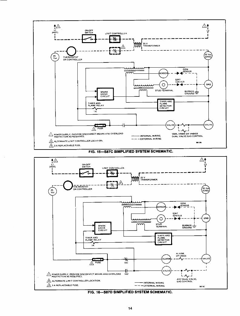
FIG 13-S87A SIMPLIFIED SYSTEM SCHEMATIC.
tn
&, ON.oFF A?
I
SWITCH
~_______c-“t__:~~[:__i_r~___--_______ 1
---
(p
r__q~ e TRANSFORMER
2s”
~H&~oyT~T------+L~+J----’ L--------_---_- ____
OR CONTROLLER
AC
-
STVD TERMINAL
4347
---++----t-
L_* SPARK DRIVE
BURNER 1-
__, CIRCVIT GROUND =
. \ -
TIMER AND ::“A,“,““”
0
FLAME RELAY
,c- DETECTOR CIRCUIT
IK
n 1 POWER SUPPLY. PROVIDE DISCONNECT MEANS AND OVERLOAD PROTECTION AS REQUIRED.
n
-INTERNAL WIRING AN” DUAL VALVE
2 ALTERNATE LIMIT CONTROLLER LOCATION. ---EXTERNALWIRING GAS CONTROL
n 3 3 A REPLACEABLE FUSE. 91168
-._ __ -__- _.__-. ._.-- -_------ ---,e..rr,r rlci. 14--23876 SIMPLIFIED SYSTEM SCXcmrr I ,b.
13 68-0039-l
n ] POWER *“PPLY. PROVlDE DISCONNECT MEANS AND OVERLOAD “845. “FE845 OR “RB450 PROTECTION AS REQUIRED. - lNTERNAL WIRING DUAL VALVE GAS CONTROL
I2
- - -EXTERNAL WIRING 2 ALTERNATE LIMIT CONTROLLER LOCATION.
91198
3 3 A REPLACEABLE FUSE.
FIG. 15-S87C SIMPLIFIED SYSTEM SCHEMATIC.
tn I I
,“LdT, ON-OFF SWlTCH
~_______~+__:~~[:I__;i-____----_______t.i I
--- THERMOSTAT 00 ___________~~Ju===rYO::-____________
25 OR CONTROLLER
“ac
.
__* SPARK DRlVE
__* CIRCUIT
- TIMER AND ~4)
TIMER AND FLAME FLAME RELAY DETECTOR
,b * - CIRCUIT
1K ,
ALARM (IF USED,
--+----- VALVE
4
--*_++--__A
n I POWER SUPPLY. PROVIDE DISCONNECT MEANS AND OVERLOAD PROTECTION AS REQUIRED. !_+-I
ALTERNATE L,M,T CONTROLLER LOCATION.
2 3 A REPLACEABLE FUSE.
ANY DUAL VALVE 2
-INTERNAL WIRING GAS CONTROL
---EXTERNAL WIRING 901 IC
FIG. 18-S87D SIMPLIFIED SYSTEM SCHEMATIC.
14

Lo! L -_--_--_-_sE~~~_____+~~~i~~~ :__________?F t t I
SOT) ‘i’ COMB”STION AIR
I BLOWER MOTOR
L-- a 0 Q --------v
j I
I I r RELAY I
I COIL
L_____-______+ENTACT__I I I I I
AIR
r____+_--T
PROVING ’ AIR BLOWER RELAY COIL
TIMER AN0
n I POWER SUPPLY. PROVIDE DISCONNECT MEANS AND OVERLOAD PROTECTION AS REQVIRED.
2 ALTERNATE LlMlT CONTROLLER LOCATION.
2 3 A REPLACEABLE FUSE.
- INTERNAL WIRING
---EXTERNAL WlRlNG
ANY DUAL VALVE GAS CONTROL
11.396A
15 68-0039-l

DRIVE TERMINAL
GROUND = ___* CIRCUIT
, . .
TlMER AND 41 TlMER AND FLAME FLAME RELAY DETECTOR
- CIRCUIT
41
ANY DUAi VALVE
n GAS CONTROL 1 MWER SUPPLY. PROVIDE DISCONNECT MEANS AND OVERLOAD
PROTECTlOW AS REOVIRED. - INTERNAL WIRING
n 2 ALTERNATE ,_,MlT CONTROLLER LOCATION. ---EXTERNAL WIRING 11.391A
The replacement S87 must have the same lock- out timing as the old control to avoid possible
Disconnect power to prevent electrical shock or equipment damage.
1. Choose the replacement S87. The replacement must have the same lockout timing as the old control.
2. Disconnect the ignition cable and the sensor wire from the S825.
3. Disconnect the leads from the quick-connect terminals on the S825, marking each lead with the S825 terminal name as you remove it.
4. Remove the set aside the S825 module. 5. Mount the S87 in the same location as the S825.
Use No. 6-32 machine screws or No. 8 sheetmetal screws 1 inch long. Fasten securely.
6. Check the wires and ignition cable. Replace any wires that appear cracked or damaged.
7. Make sure the system is firmly grounded to the burner. A screw is provided on most burners to simplify
16

I L
grounding. If you are uncertain of the existing ground, simply run a wire from the GND (BURNER) terminal on the S87 to the burner ground screw and attach it firmly. More than one ground will not hurt. Earth ground is not required with S87.
8. Connect the ignition cable and the sensor wire to the S87.
9. Wire the S87 using the appropriate cross refer- ence chart below. The gas control and the thermostat must be powered from the same transformer when the S87 is used. Some S825 systems had two transformers; in this type of system, rewire to use only one trans- former with minimum 40 VA load rating.
CONVERSION FROM S825A TO S87C,D
LEAD FROM I CONNECT TO
aThe ALARM terminal on S87D is not used in this application.
CONVERSION FROM S825B TO S87D
LEAD FROM I
CONNECT TO S825B TERMINAL S87D TERMINAL
2. Remove and discard lead that was connected to S825 terminal 5.
3. Make remaining wiring changes:
LEAD FROM I CONNECT TO
aSome S825 models have a terminal labeled GND and one labeled T2. On these models, connect T2 and GND from S825 to 25 V (GND) and GND (BURNER), respectively, on S87.
CONVERSION FROM S825D WITH TWO TRANSFORMERS AND TWO GAS CONTROLS TO S87D
1. Disconnect gas controls and alarm relay (if used) from transformer.
2. Connect alarm relay and temperature controls to one transformer with minimum 40 VA load rating. Remove other transformer.
3. Connect gas control transformer lead to upper S87D terminal labeled VALVE.
4. Remove and discard lead that was connected to S825 terminal 5.
5. Make remaining wiring changes:
4 ALARM 5 VALVE (upper) 3 VALVE (lower)
T2 25 V (GND) 24 V-T1 25 V
GND ! GND (BURNER)
LEAD FROM CONNECT TO S825D TERMINAL S87D TERMINAL
4 ALARM 3
GRD/T2a Tl or 24 V-T1
VALVE (lower) 25 V (GND) 25 V
CONVERSION FROM S825C TO S87C,D SINGLE-STAGE OR TWO-STAGE SYSTEM
LEAD FROM S825C TERMINAL
VALVE-5 VALVE-3
GRD/T2a.b Tl or 24 V-T1 b
CONNECT TO S87C,D TERMlNALc
VALVE (upper) VALVE (lower)
25 V (GND) 25 v
aSome S825C models have a terminal labeled GND and one labeled T2. On these models, connect T2 and GND from S825 to 25 V (GND) and GND (BURNER), res- pectively, on S87.
blf a second gas valve is connected between GRD/T2 and 24 V-Tl, move the 24 V-T1 lead to VALVE (upper) and the GRDIT2 lead to VALVE (lower). The two valves will now be connected in parallel.
‘The ALARM terminal on S87D is not used in this application.
\ \-
CONVERSION FROM S825D WITH SINGLE VALVE AND ONE TRANSFORMER TO S87D
1. Disconnect gas control from transformer and connect to upper 587 terminal labeled VALVE. Make sure other controls are still connected to transformer.
aSome S825 models have a terminal labeled GND and one labeled T2. On these models, connect T2 and GND from S825 to 25 V (GND) and GND (BURNER), respectively, on S87.
CONVERSION FROM S825D WITH DUAL VALVE GAS CONTROL AND SINGLE TRANSFORMER TO S87D
1. Disconnect gas control TH lead from transformer and connect to upper VALVE terminal on S87D. Make sure other controls are still connected to transformer.
2. Remove and discard lead that was connected to S825 terminal 5.
3. Make remaining wiring connections:
LEAD FROM I CONNECT TO
aSome S825 models have a terminal labeled GND and one labeled T2. On these models, connect T2 and GND from S825 to 25 V (GND) and GND (BURNER), respectively, on S87.
17 68-0039-l
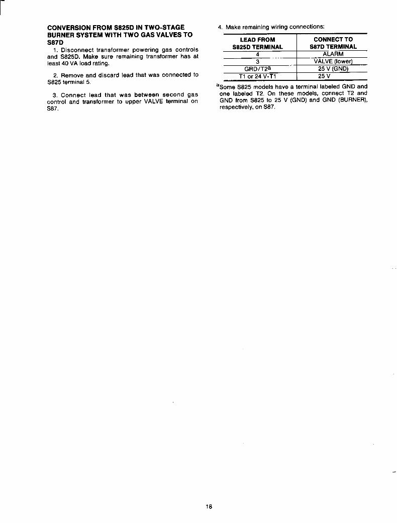
CONVERSION FROM S825D IN TWO-STAGE BURNER SYSTEM WITH TWO GAS VALVES TO S87D
1. Disconnect transformer powering gas controls and S825D. Make sure remaining transformer has at least 40 VA load rating.
2. Remove and discard lead that was connected to S825 terminal 5.
3. Connect lead that was between second gas control and transformer to upper VALVE terminal on S87.
4. Make remaining wiring connections:
;
“Some S825 models have a terminal labeled GND and one labeled T2. On these models, connect T2 and GND from S825 to 25 V (GND) and GND (BURNER), respectively, on S87.
18