657284 . . . . p.0. 1 ot hi. ecn - digital...
TRANSCRIPT
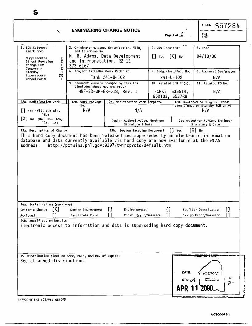
ENGINEERING CHANGE NOTICE \ P.0. 1 ot 2
2. ECN Category (mark one)
Supplemental [I Di rec t Revision 11 Change ECN 11 Temporary 11 Standby [I supersedure [ X I Cancel/Void [I
657284 ........ . . . . . . . . . . . . . . . . . . . . . . . . . . . . . . hi. ECN
12a. Mod i f i ca t i on Work
[ ] Yes (fill out Elk. 12b>
Design Authority/cog. Engineer Signature & Date
.__, [ X I No (NA Elks. 12b,
12c. 12d) Design AuthoritylCog. Engineer
Signature & Date
3. Or ig ina to r ' s Name, Organization, MSIN, and Telephone No.
M. R. Adams, Data Development and Interpretation, R2-12, 373-6167 6 . Project Title/No./Work Order No.
Tank 241-U-102 9 . Document Numbers Changed by t h i s ECN
( includes sheet no. and rev.)
HNF-SD-WM-ER-618, Rev. 1
12b. Work Package 12c. Modi f icat ion Work
4. US0 Required?
[ ] Yes [ X I No
7. Sldg./Sys.lFac. NO.
241-U-102 10. Related ECN Noes).
ECNs: 635514, 650103, 653788
5. Date
04/10/00
8. Approval Designator
N / A 11. Related PO No.
'd t o Or ig ina l Condi- o r Standby ECN only)
N/A
13a. Descr ip t ion of Change 13b. Design Baseline Document? [ I Yes [ X I No
This hard copy document has been released and superseded by an electronic information database and data currently available via hard copy are now available at the HLAN address: http://pctwins .pnl .gov:9397/twinsproto/defaul t. htm.
14a. J u s t i f i c a t i o n (mark one)
C r i t e r i a Change [x] Design lrnprovement [ ] Environmental 11 F a c i l i t y Deact ivat ion [ ] As-Found [ I F a c i l i t a t e Const [ ] Const. ErrorlOmission [ ] Design Error/Omission [ ] 14b. J u s t i f i c a t i o n De ta i l s
Electronic access to information and data is superseding hard copy document.
15. D i s t r i b u t i o n ( inc lude name, MSIN, and no. o f copies)
See attached distribution.
DATE:
APR 11 -_pu=_____
A-7900-013-2 (05 /96 ) GEF095
A-79000191
ENGINEERING CHANGE NOTICE
ENGINEERING CONSTRUCTION V e r i f i c a t i o n Required
[ I [ I
Improvement
Delay
Ind icate the re la ted docments (other than the engineering documents i d e n t i f i e d on s ide 1)
[ I $ [ I $
[ I [ I 11
Addit ional
Savings
tha t w i l l be affected by the change described i n Black 13.
[ I $ [ I $
Addi t ional
Savings [ I Yes
[ X I NO
19. Change Impact Review:
SDDIDD
:unctional Design C r i t e r i a
)perat ing Spec i f i ca t i on
Enter the af fected document number i n Block 20.
[ I [ I [ I
Tank Ca l i b ra t i on Manual
Health Physics Procedure Spares Mu l t i p le U n i t L i s t i ns
SeismicIStress Analysis
StressIDesign Report
In ter face Control Drawing
[ I [ I [ I
1. ECN (use no. from pg. 1)
page 2 of 2 ECN-657284
[ I
r i
Cal ibrat ion Procedure [ I : r i t i c a l i t y spec i f i ca t i on
:onceptual Design Report r l I n s t a l l a t i o n Procedure
[ I Test ProceduresISpecif icat io n Component Index r i .. _. - _
ri ASME Coded Item r i Maintenance Procedure :qui p e n t Spec. r i :onst. Spec.
'rocurement Spec.
.- [ I r i
_ _ _ _ [ I r i
Human Factor Consideration Computer software
[ I Operating Ins t ruc t i on r i Engineering Procedure
L _ _ _ 8.2
[ I [ I [ I [ I [ I [ I [ I
[ I [ I
[ I [ I [ I [ I [ I [ I
ELectr ic C i r c u i t Schedule I C R S Procedure
Process Control
Process Flou Chart
Purchase Requis i t ion
T i ck le r F i l e
Operating Procedure
Operational Safety
IEFD Drawing
Ce l l Arrangement Drawing
Essential Material
Fac. Proc. Samp. Schedule
Inspection P l a n
Inventory Adjustment
[ I
[ I [ I
[ I [ I
lendor Information
)M Manual
iSARISAR
safety Equipment L i s t
tad iat ion Work Permit
'nvironmental Impact statement !nviromental Report
invironmental Permit
3. Other Affected Documents: (NOTE: Documents l i s t e d belou w i l l not be revised by t h i s ECN.) Signatures below
[ I Requirement
[ I Hanual/Plan
[ I Speci f icat ion
[ I Request
i nd i ca te that the s ign ing organization has been n o t i f i e d of other affected documents l i s t e d below. Document Number/Revision Document NumberlRevision Document Number Revision
N I A
21. Approvals
Signature Date Ies ign Au tho r i t y
Log. Eng. M. R . Adams
cog. Mgr. J. G. F i e l d
?A
/22/1*
Safety
I n v i ron.
3ther
signature Design Agent
PE
PA
Safety
Design
Environ.
other
DEPARTMENT OF ENERGY
Signature or a Control Nlvnber tha t tracks the Approval Signature
ADDIT IONAL
Date
A-7900-013-3 (05196) GEF096

1 HNF-SD-WM-ER-618, Rev. 1
Tank Characterization Report for Single-Shell Tank 241 -U-I 02
M. R. Adam CH2M H i l l Han fo rd Group, Inc . , R ich land, WA 99352 U.S. Department o f Energy C o n t r a c t 8023764-9-KO01
EDT/ECN: ECN-657284 UC: 2070 Org Code: 74B20 CACN/COA: 102227/A020 B&R Code: EW 3120074 T o t a l Pages: 2&
Key Words: Waste C h a r a c t e r i z a t i o n , S i n g l e - S h e l l Tank, SST Tank 241-U-102, Tank U-102, U-102, U Farm, Tank C h a r a c t e r i z a t i o n Repor t , TCR, Waste I n v e n t o r y , TPA M i l e s t o n e M-44
A b s t r a c t : N/A
h t t p : / / p c t w i n s .pn l .gov:9397/twinsproto/defaul t. htm
TRADEMARK DISCLAIMER. t rade name, trademark, manufacturer, or otherwise, does not necessari ly cons t i tu te o r imply i t s endorsement, recommendation, or favor ing by the United Sta tes Government or any agency thereof or i t s contractors or subcontractors.
Pr in ted i n the United States of America. To obtain copies o f t h i s document, contact: WHC/BCS Document Control Services, P.O. Box 1970, Mai lstop H6-08, Richland UA 99352, Phone (509) 372-2420; Fax (509) 376-4989.
Reference herein t o any spec i f i c commercial product, process, o r service by
4(//*/00 "Date'
Approved for Public Release A-6400.073 (10/95) GEF321

(1) D o a n t W L & ~ RECORD OF REVISION
HNF-SO-WM-ER-618
Tank Characterization Report for Single-Shell Tank 241-U-102
PIP. 1
1 0-B Rs Incorporate p e r E C N - 6 5 0 1 0 3 . M.J. Kupfer K.M. Hodgsan
' ,kJ7<.yd-. m, F 4.F/
1 I I
I 0-B Rv Incorporate p e r E C N - 6 5 0 1 0 3 . I M.J. Kupfer 1 K.M. Hodgsan
I I I I I
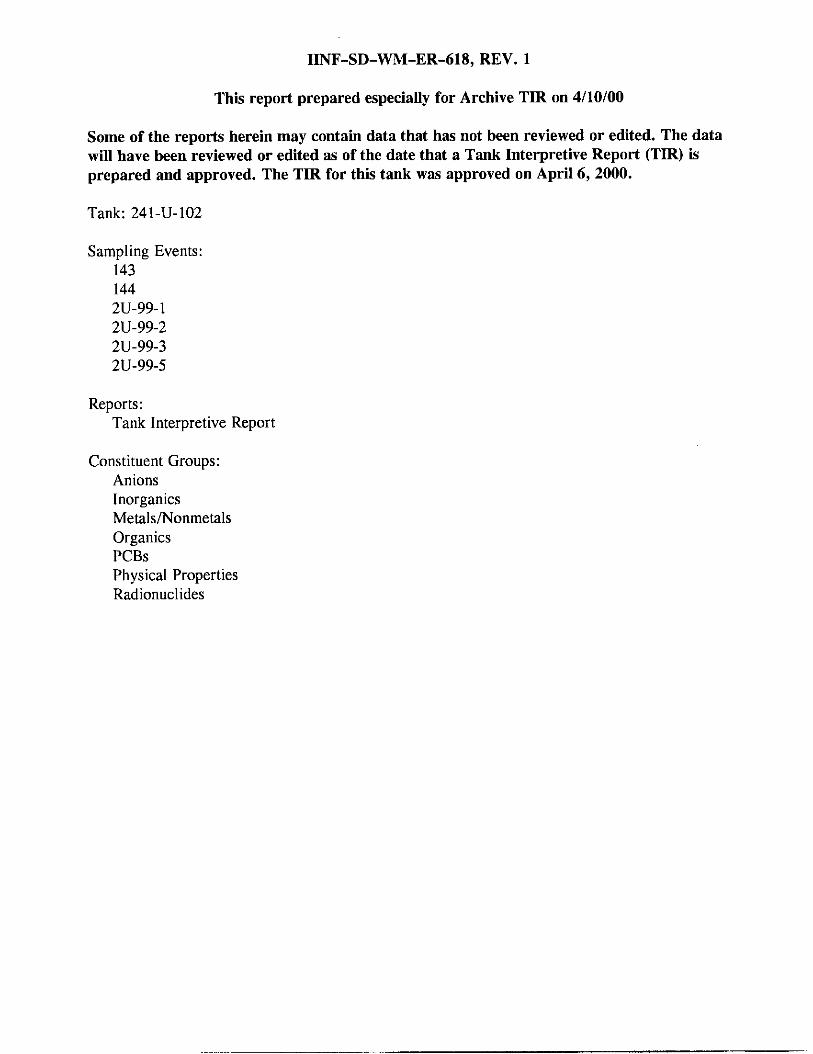
HNF-SD-WM-ER-618, REV. 1
This report prepared especially for Archive TIR on 4/10/00
Some of the reports herein may contain data that has not been reviewed or edited. The data will have been reviewed or edited as of the date that a Tank Interpretive Report (TIR) is prepared and approved. The TIR for this tank was approved on April 6,2000.
Tank: 241-U-102
Sampling Events: 143 144 2U-99-1 2U-99-2 2U-99-3 2U-99-5
Reports: Tank Interpretive Report
Constituent Groups: Anions Inorganics Metals/Nonmetals Organics PCBs Physical Properties Radionuclides
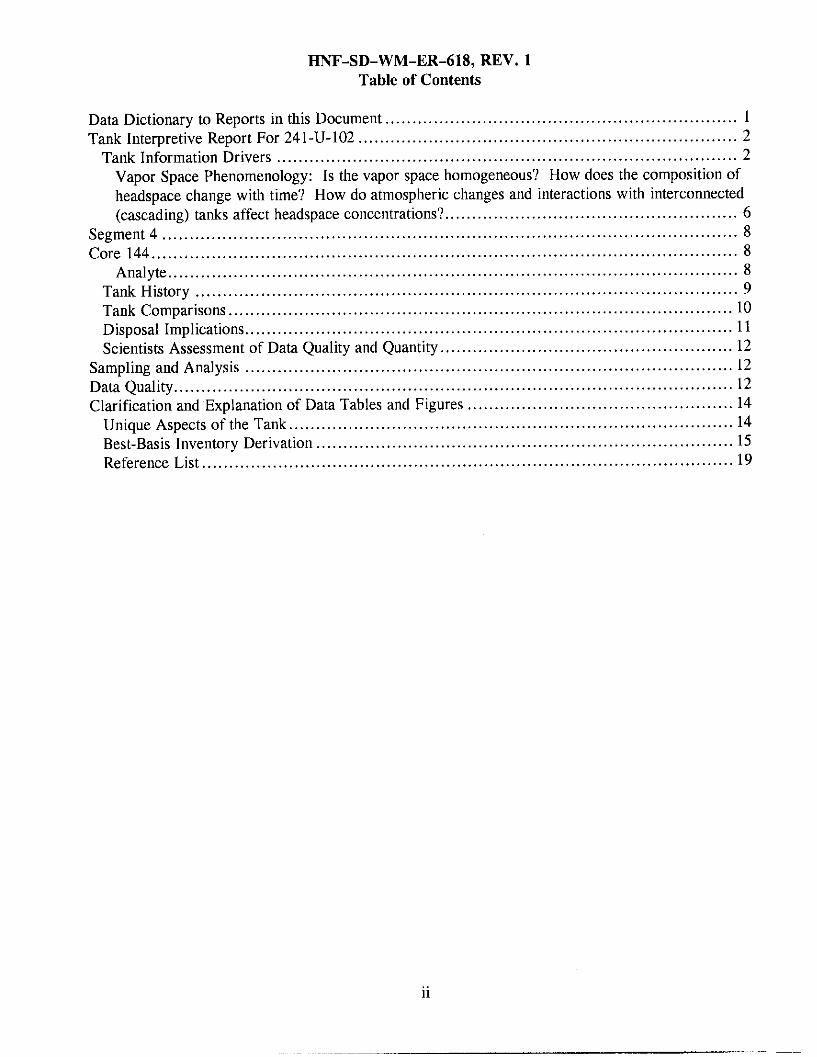
HNF.SD.WM.ER.618, REV . 1 Table of Contents
Data Dictionary to Reports in this Document ................................................................. 1 Tank Interpretive Report For 241-U-102 ...................................................................... 2
Tank Information Drivers ..................................................................................... 2 Vapor Space Phenomenology: Is the vapor space homogeneous? How does the composition of headspace change with time? How do atmospheric changes and interactions with interconnected (cascading) tanks affect headspace concentrations? ...................................................... 6
Segment 4 .......................................................................................................... 8 Core 144 ............................................................................................................ 8
Analyte ......................................................................................................... 8 Tank History .................................................................................................... 9 Tank Comparisons ............................................................................................. 10 Disposal Implications .......................................................................................... 11 Scientists Assessment of Data Quality and Quantity ...................................................... 12
Clarification and Explanation of Data Tables and Figures ................................................. 14
Best-Basis Inventory Derlvatlon ............................................................................. 15
Sampling and Analysis .......................................................................................... 12 Data Quality ....................................................................................................... 12
Unique Aspects of the Tank .................................................................................. 14
Reference List .................................................................................................. 19
. .
.. 11

HNF-SD-WM-ER-618, REV. 1
Data Dictionary to Reports in this Document
Report Field Description
Tank Interpretive Report ..... ............................................................
Interprets information about the tank answering a series of seven questions covering areas such as information drivers, tank history, tank comparisons, disposal implications, data quality and quantity, and unique aspects of the tank.
1
HNF-SD-WM-ER-618, REV. 1
Tank Interpretive Report For 241-U-102
Tank Information Drivers
Question I : What are the information drivers applicable to this tank? What type of information does each driver require from this tank? (Examples of drivers are Data Quality Objectives, Mid-Level Disposal Logic, RPP Operation and Utilization Plan, test plans and Letters of Instruction.) To what extent have the information and data required in the driving document been satisfied to date by the analytical and interpretive work done on this tank?
The information drivers for tank 241-U-102 include the Tank Safety Screening Data Quality Objective (Dukelow et al. 1995). the Data Quality Objective to Support Resolution of the Flammable Gas Safety Issue (Bauer and Jackson 1998), the Data Quality Objectives for Generic In-Tank Health and Safety Vapor Issue Resolution, (Osborne et ai. 1995), the Data Quality Objective to Support Resolution of the Organic Solvent Safety Issue (Meacham et al. 1997), the Memorandum of Understanding for the Organic Complexant Safety Issue Data Requirements (Schreiber 1997), the Data Quality Objectives for the Waste Compatibility Program (Fowler 1995), the Data Quality Objectives for Tank Farms Waste Compatibility Program (Mulkey, Miller, and Jackson 1998), and the Historical Model Evaluation Data Requirements (Simpson and McCain 1997). The extent to which these information drivers have been satisfied is discussed below.
Safety Screening DQO: Does the waste pose or contribute to any recognized potential safety problems?
The data needed to screen the waste in tank 241-U-102 for potential safety problems are documented in Tank Safety Screening Data Quality Objective (Dukelow et al. 1995). These potential safety problems are exothermic conditions in the waste, flammable gases in the waste and/or tank headspace, and criticality conditions in the waste. A full vertical profile of the tank waste, taken from two risers separated as widely as practicable, is required for the Safety Screening analysis. The push mode core sampling method was used to obtain cores 143 and 144 from tank 241-U-102 per the requirements of Hu (1996b). Because of the hardness of the waste, both cores 143 and 144 were incomplete. After initial unsuccessful attempts to collect full cores 143 and 144 from risers 19 and 9, respectively, a second attempt was made to collect segment 6A from riser 19. The sampler was empty. The waste at the bottom of the tank was too hard to penetrate in the push mode. Approximately 1 to 1 ‘/z segments of each core remained unsampled at the bottom of the tank. This can be seen graphically in the “Core Profiles” Standard Report.
Results obtained using differential scanning calorimetry (DSC) indicated that two of the 1996 core samples obtained from tank 241-U-102 exceeded the safety screening decision threshold of 480 J/g evaluated on a dry weight basis. Samples from core 143, segment 2, upper and lower half, exhibited mean DSC dry weight results of 534 J/g and 618 J/g, respectively (Hu 1999b). The upper limits to a one-sided 95 percent confidence interval on the mean for the samples from core 143, segment 2, were 872.46 J/g dry weight from the upper half and 658 J/g dry weight from the lower half. As discussed in the “Organic Complexant Safety Issue MOU” section, the reactive systems screening tool (RSST) was used to screen the sample exhibiting the highest DSC result. The duplicate sample
n

HNF-SD-WM-ER-618, REV. 1 from core 143, lower half exhibited a DSC result of 624 J/g. The sample exhibited very weak propagating reactions. In addition, the mean weight percent water for core 143, segment 2 upper and lower half were 50.9 weight percent water and 49.7 weight percent water, respectively. The total organic carbon (TOC) contents on a dry weight basis of the samples from core 143, segment 2, upper and lower half were 15,000 pg/g and 16,300 pg/g, respectively The maximum average exotherm from the 1999 grab samples was from sample 2U-99-5 decanted sludge sample. The sample pair exhibited mean DSC results of 62.1 J/g dry weight, and the maximum upper limit to the 95 percent confidence interval on the mean for that sample-duplicate pair was 80.9 J/g dry weight. The analytical data indicate that energetics are not a concern for tank 241-U-102.
As requested in Hu (1996a), samples of the headspace of tank 241-U-102 were obtained for measurement. Prior to obtaining the core samples, the headspace was measured for flammability. The results were reported as 0 percent of the Lower Flammability Limit (LFL) (Hu 1999b).
The threshold limit for criticality, based on the total alpha activity, is 1 g/L. Assuming that all alpha activity is from 239Pu, and, using the maximum sample density of 1.88 g/mL, 1 g/L of 239Pu is equivalent to 32.7 pCi/g of alpha activity. The maximum total alpha mean result from the 1996 core samples was 0.634 pCi/g, from core 144, segment 1, lower half. The 95 percent confidence interval upper limit on the mean for that sample-duplicate pair was 0.697 pCi/g. The maximum mean total alpha result from the 1999 grab settled solids samples was obtained from sample 2U-99-5 sludge and exhibited a mean of 0.588 pCi/g, with a 95 percent confidence interval upper limit on the mean of 0.624 pCi/g. Therefore, criticality is not a concern for this tank.
The requirement of the Tank Safety Screening Data Quality Objective (Dukelow et al. 1995) that a profile of the tank waste be acquired from two risers separated as widely as practicable was fulfilled. According to Reynolds et al. (1999), the sampling and recovery from tank 241-U-102 were less than optimal, but were adequate to satisfy the requirements of Dukelow et al. (1995).
Flammable Gas DQO: Does a possibility exist for releasing flammable gases into the headspace of the tank or releasing chemical or radioactive materials into the environment?
The requirements to support the flammable gas issue are documented in the Data Quality Objective to Support Resolution of the Flammable Gas Safety Issue (Bauer and Jackson 1998). The Flammable Gas Data Quality Objective (DQO) has been extended to apply to all tanks. Analyses and evaluations will change according to program needs until this issue is resolved. Final resolution of the flammable gas safety issue is expected by September 30, 2001 (Johnson 1997).
As stated in the safety screening DQO section, the headspace vapor measurements performed in 1996 and 1999 all show results well below the action limit of 25 percent of the LFL.
Tank 241-U-102 is equipped with a standard hydrogen monitoring system (SHMS) for the collection of vapor-phase data that support resolution of flammable gas issues. The SHMS monitors hydrogen continuously. From the installation date (May 1998) through June 1999, 2 hydrogen gas release events (GREs) were documented for tank 241-U-102 based upon SHMS data. The maximum volume of hydrogen released from tank 241-U-102 in a single GRE was 1.47 m3 during August 28, 1998 to August 31, 1998. The maximum concentration of hydrogen during a GRE measured by the SHMS was 760 ppm on May 3, 1999. Recent interim stabilization activities have resulted in an increased hydrogen concentration in the tank domespace. As of March I , 2000, the
3

HNF-SD-WM-ER-618, REV. 1 maximum hydrogen measured in tank 241-U-102 was 2,170 ppm, not associated with a GRE (McCain 2000). All readings have been well below the SHMS action level of 6,250 ppin of hydrogen. These releases are documented in Results of Vapor Space Monitoring of Flammable Gas Watch List Tankr (McCain 1999).
The results of headspace monitoring by installed SHMS equipment and by grab samples indicate that, with the present work controls in place, the flammable gases in tank 241-U-102 do not present a recognized safety hazard.
Hazardous Vapor Screening DQO: Do hazardous storage conditions exist associated with gases and vapors in the tank?
In 1997, samples of the tank 241-U-102 headspace vapor were collected and analyzed by the Special Analytical Support vapor team per the requirements of Buckley (1997) and Osborne et al. (1995). The results are documented in the Tank Vapor Sampling and Analysis Data Package for Tank 241-U-102 Sampled December 18, 1997(Duchsherer et al. 1998). A number of analytes were detected at levels above their respective Vapor Program Required Quantitation Limits, notably ammonia (660 ppmv), nitrous oxide (1 100 ppmv), and hydrogen (1100 ppmv). The ammonia concentration exceeded the limits for breathing air. It should be noted, however, that the sample was not taken in the worker's breathing zone, but in the tank headspace.
Organic Solvent Safety Issue DQO: Does an organic solvent pool exist that may cause a fire or ignition of organic solvents in entrained waste solids?
The data needed to address the organic solvent screening issue are documented in Data Quality Objective to Support Resolution of the Organic Solvent Safety Issue (Meacham et al. 1997). The DQO requires that headspace samples be analyzed for total nonmethane organic compounds. Vapor samples were taken from tank 241-U-102 December 18 1997, and the total nonmethane organic vapor concentration calculated from the concentration of individual compounds by gas chromatography/mass spectrometry was about 5.2 mg/m' at a temperature of 25°C and 1 atmosphere of pressure (Duchsherer et al. 1998). These samples were collected in SUMMA'" canisters .
The organic program has determined that even if an organic solvent pool does exist, the consequence of a fire or ignition of organic solvents is below risk evaluation guidelines for all tanks (Brown et al. 1998). The organic solvent issue is expected to be closed for all tanks in 2000.
Organic Complexant Safety Issue MOU: Does the possibility exist for a point source ignition in the waste followed by a propagation of the reaction in the solid/liquid phase of the waste?
The data required for the organic complexant issue are documented in Memorandum of Understanding for the Organic Complexant Safety Issue Data Requirement (Schreiber 1997). Differential scanning calorimetry and TOC analyses were performed to address the organic complexant issue.
As discussed in the safety screening DQO section, two of the 1996 core samples obtained from tank 241-U-102 exhibited DSC results that exceeded the safety screening decision threshold of 480 J/g
4

HNF-SD-WM-ER-618, REV. 1 evaluated on a dry weight basis. None of the samples from the 1999 grab sample exceeded the safety screening decision threshold.
The maximum mean TOC value from the 1996 core samples was 17,800 pg/g in core 144, segment 1, drainable liquid, which on a dry weight basis was 2.45 weight percent (Steen 1998). The maximum TOC results from the 1999 grab samples came from sample 2U-99-2 decanted sludge sample. The mean TOC value was 11,400 pg/mL (7,680 pg/g), which equaled 1.46 weight percent on a dry basis (Steen 1999). All values from the core and grab samples were well below the organic complexant action level of 4.5 percent dry weight.
The organic DQO requires that the single sample with the highest DSC results be tested with adiabatic calorimetry testing. The highest single DSC value observed was 624 J/g dry weight from the duplicate samples of core 143, segment 2, lower half. The reactive systems screening tool was performed on this sample, which exhibited very weak propagating reactions (Bechtold 1996).
The data suggest that a propagating reaction in the waste is unlikely. The organic complexants safety issue was closed for all tanks in December 1998 (Owendoff 1998).
Compatibility DQO: Will safety problems be created as a result of mixing waste in interim storage? Do operations issues exist which should be addressed before waste is transferred?
The requirements of the Tank Farms Waste Transfer Compatibility Program (Fowler 1999b) include the safety considerations and decision rules for criticality, corrosion, emissions, energetics, and flammable gas accumulation. The operational issues of heat generation of commingled waste, segregation of complexant waste, and high phosphate waste are addressed in Data Quality Objectives for Tank Farms Waste Transfer Compatibility Program (Fowler 1995).
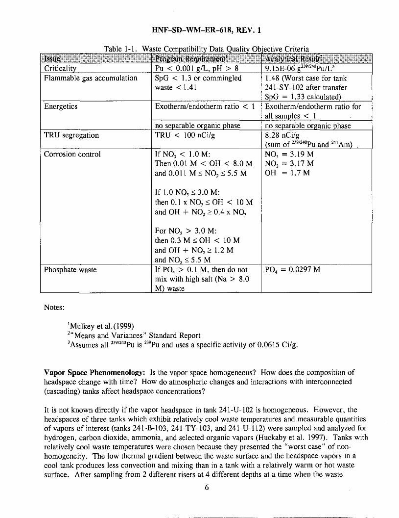
Saltwell pumping of tank 241-U-102 to tank 241-SY-102 began on January 20, 2000, and is projected to continue intermittently over the next 1-2 years. A compatibility assessment using the 1999 grab sample results was completed prior to the start of saltwell pumping. The analytical results are reported in Steen (1999), and assessed in Fowler (1999~). All requirements for transfer were met. In addition, assurance that tank 241-U-102 would remain within specifications for fuel content and distribution was demonstrated in Fowler (1999a). The time to reach 25 percent of the LFL in tank 241-SY-102 (55 days) if the ventilation system was shut down was presented in Hu (1999a). Table 1-1 lists the compatibility issues, the compatibility requirements for the issues, and the analytical results from the compatibility grab samples obtained in 1999.
5
HNF-SD-WM-ER-618, REV. 1
Table 1-1. W
Criticality Flammable gas accumulation
Energetics
TRU segregation
Corrosion control
Phosphate waste
;te Compatibility Data Quality 01 Program Requirement ‘ Pu < 0.001 g/L, pH > 8 SpG < 1.3 or commingled waste < 1.41
Exotherm/endotherm ratio < 1
no separable organic phase TRU < 100nCi/g
If NO, < 1.0 M: Then 0.01 M < OH < 8.0 M and 0.01 1 M 5 NO, 5 5.5 M
If 1.0 NO, 5 3.0 M: then 0.1 x NO, 5 OH < 10 M and OH + NO, 2 0.4 x NO,
For NO, > 3.0 M: then 0.3 M 5 OH < 10 M and OH + NO, 2 1.2 M and NO, 5 5.5 M If PO, > 0.1 M, then do not mix with high salt (Na > 8.0 M) waste
1.48 (Worst case for tank 241-SY-102 after transfer SpG = 1.33 calculated) Exotherm/endotherm ratio for 111 samples < 1
3.28 nCi/g [sum of 239’240Pu and %lAm) ‘40, = 3.19 M YO, = 3.17 M 3H = 1 .7M
PO., = 0.0297 M
~~~
Notes:
‘Mulkey et aL(1999) ’“Means and Variances” Standard Report Assumes all 239n4aP~ is 239Pu and uses a specific activity of 0.0615 Ci/g. 3
Vapor Space Phenomenology: Is the vapor space homogeneous? How does the composition of headspace change with time? How do atmospheric changes and interactions with interconnected (cascading) tanks affect headspace concentrations?
It is not known directly if the vapor headspace in tank 241-U-102 is homogeneous. However, the headspaces of three tanks which exhibit relatively cool waste temperatures and measurable quantities of vapors of interest (tanks 241-B-103, 241-TY-103, and 241-U-112) were sampled and analyzed for hydrogen, carbon dioxide, ammonia, and selected organic vapors (Huckaby et al. 1997). Tanks with relatively cool waste temperatures were chosen because they presented the “worst case” of non- homogeneity. The low thermal gradient between the waste surface and the headspace vapors in a cool tank produces less convection and mixing than in a tank with a relatively warm or hot waste surface. After sampling from 2 different risers at 4 different depths at a time when the waste
6

HNF-SD-WM-ER-618, REV. 1 temperature was at or near the temperature of the headspace vapors, it was found that the headspaces of all 3 tanks were homogeneous for all intents and purposes. Tank 241-U-102 exhibits cool temperatures and measurable quantities of a variety of headspace vapors. The results and conclusions of the study indicate that, unless a reason for heterogeneity exists, such as a GRE, or the opening of a large riser in the tank, the headspace in tank 241-U-102 is most likely homogeneous.
Tank 241-U-102 is passively ventilated and has its own filtered breather riser. As barometric pressure falls, the tank may exhale air, waste gases, and vapors. Barometric pressure typically rises and falls on a diurnal cycle, producing in passively ventilated Hanford waste storag an average daily exchange of air equal to about 0.46 percent of each tank headspace (Huckaby 1994). Changes in the concentration of tank headspace due to barometric pressure changes are consequently very slow. The ventilation rate of tank 241-U-102 was measured using a tracer gas. The gas was injected into the tank headspace and its concentration measured as a function of time. Huckaby et al. (1998) reported average ventilation rates of 2.7 m’/hr to 4.8 m’/hr (96 ft’/hr to 168 ft’/hr). The tank was also found to exchange headspace vapors with tank 241-U-103 through the cascade line at estimated rates of 1.6 m’/hr to 12.6 m3/hr (57 ft3/hr to 445 ft3/hr).
Historical Model DQO: Is the waste inventory generated by a model based on process knowledge and historical information (Agnew et al. 1997a) representative of the current tank waste inventory?
The purpose of the historical evaluation is to determine whether the Hanford defined waste (HDW) model, based on process knowledge and historical information (Agnew et al. 1997a), agrees with current descriptions of tank inventories based on sampling. Historical DQO issues (Simpson and McCain 1997) have largely been replaced by the Best-Basis Inventory assessment (see Question 7). The following discussion of the historical DQO evaluation is presented for information.
The historical DQO identifies the waste type of interest for tank 241-U-102 as 242-T Evaporator saltcake (SMMT2). The SMMT2 saltcake occupies approximately 80 inches of the tank height and was sampled by segments 3, 4, 5, and 6 of cores 143 and 144. In the evaluation, a gateway analysis is performed by comparing analytical results with DQO-defined concentration levels for the key analytes in the SMMT2 saltcake. If the analytical results are 2 1 0 percent of the DQO-defined levels and the sum of the analyte masses 2 8 5 percent of the sum for the historical waste stream, the waste type and layer identification are considered acceptable for use as comparisons to the HDW model (Simpson and McCain 1997).
The key analytes for SMMT2 saltcake are sodium, aluminum, chromium, percent water, nitrate, and sulfate. A comparison of the analytical results from cores 143 and 144 segments 3, 4, 5, and 6 exhibited close agreement for the key analytes. Table 1-2 lists the key analytes and their Concentrations from the core segments thought to comprise the SMMT2 saltcake in the tank. As can be seen in Table 1-2, all key analytes exhibited concentrations 2 10 percent of the values listed in the historical DQO, and 5 of the eight core segments exhibited a total analyte mass of 2 85 percent of the total of the historical DQO values.
7

HNF-SD-WM-ER-618, REV. 1
Table 1-2. Comparison of Tank 241-U-102 SMMT2 Saltcake Key Analyte Mean Concentrations with
Notes: ‘Failed the 85 percent total mass criterion, i.e., key analytes did not comprise 2 85 percent of the total mass. ‘Simpson and McCain (1997) 3Acid digestion results.
Heat Load Estimate: A factor in assessing tank safety is the heat generation and temperature of the waste. Heat is generated in the tanks from radioactive decay. The heat load estimate based on the process history was 2.93 kW (10.000 Btu/hr) (Agnew et al. 1997a). The heat load estimate based on the tank headspace temperature was 1.67 kW (5,710 Btu/hr) (Kummerer 1995). The tank heat load based on the Best-Basis Inventory (See Standard Report “Best-Basis Inventory [Radioactive]”) was 3.47 kW (11,800 Btu/hr). These estimates are helow the limit of 7.6 kW (26,000 Btu/hr) that separates high and low heat load single-shell tanks (Goetz 1999). Table 1-3 presents the radionuclides that are predominant in the production of heat, along with specific activity and contribution to heat load.

HNF-SD-WM-ER-618, REV. 1
Strontium-90
Cesium- 137
Total
2.22E+05 0.00669 1.49E+03
4.19E+05 0.00472 1.98E+03
. - 3.47E+03
Notes: 'Includes daughter isotopes.
Bounding Concentration Limits: Sample results from tank 241-U- 102 were screened against current bounding concentrations limits used to develop the authorization source term in accordance with HNF-SD-WM-PROC-021, Rev. 3, Section 18.0, Tables 4-1 and 4-2 (Adams 1999). One solid sample result from the analysis of vanadium was found to exceed the bounding concentration limit, which used an estimated density of 1.6 g/mL to calculate the limits. When the density from the adjacent segment in the same core was used to recalculate the bounding concentration limits for the subsamples or composites, there were no changes affecting the number of samples exceeding the bounding concentration limit for vanadium. Liquid samples from the analysis of ammonia and cesium-137 were found to exceed the bounding concentration limits. Since the analytical data do represent tank waste and there appears to be little quality assurance problems with the data, notifications were made for further study concerning those samples exceeding the bounding concentration limits.
Tank History
Question 2: What is known about the history of this tank as it relates to waste behavior?
The U Tank Farm was constructed during 1943 and 1944 in the 200 West Area. The U Tank Farm contains twelve 100-series tanks and four 200-series tanks. Built according to the first-generation design, the U Tank Farm was designed for non-boiling waste with a maximum fluid temperature of 104 "C (220 OF). Tank 241-U-102 is the second in a cascade series of three tanks that includes tanks 241-U-101 and 241-U-103. Each tank in the cascade series is set 0.305 m (1 ft) lower in elevation from the preceding tank. The cascade overflow height is approximately 4.9 m (16 ft) from the tank bottom and 0.61 m (2 ft) below the top of the steel liner. Tank 241-U-102 has a capacity of 2,006 kL (530 kgal), a diameter of 22.9 m (75.0 ft), and a liner height of 5.8 m (18 ft) as measured from the tank bottom centerline (Goetz 1999).
Agnew et al. (1997b) provides a history of the waste in the tank. Tank 241-U-102 first received metal waste (MW) from T Plant via the cascade line in the second quarter of 1946 and was full by the first quarter of 1947. Waste cascaded from tank 241-U-101 until the second quarter of 1954. In the second and fourth quarter of 1953, the third quarter of 1955, the third and fourth quarters of 1956, and the first quarter of 1957, MW from the tank was sent to U Plant for uranium recovery. The tank received MW from U Plant in the fourth quarter of 1955 and the second quarter of 1957, and in the third quarter of 1956, the tank received MW from tank 241-U-101. The tank was sluiced
9

HNF-SD-WM-ER-618, REV. 1 in the third and fourth quarters of 1955. The heel was sluiced and the tank declared empty in the first quarter of 1957. The tank received waste from tanks 241-SX-102 and 241-SX-Ill. The tank received supernatant from tanks 241-C-104, 241-TX-108, 241-TX-106, 241-TX-118, 241-SY-102, 241-U-107, and 241-U-101 between the second quarter of 1978 and the first quarter of 1979. Supernatant from tank 241-U-102 was sent to tanks 241-S-110, 241-U-111, and 241-SY-102 between the first quarter of 1974 and the third quarter of 1979. The tank received evaporator waste from tank 241-TX-106 during the second quarter of 1975. During the fourth quarter of 1977 and the first quarter of 1978, the tank received nitric acid and potassium permanganate solution waste from evaporator operations. In the fourth quarter of 1992, saltwell liquid waste was pumped from the tank to tank 241-AW-106 (CHG 2000a).
The tank was removed from service and declared inactive in 1979. The tank was partially isolated in 1982. An anomalous liquid observation well (LOW) indication of the liquid level above that of the supernatant and solids level was resolved in mid-January 1999 when it was discovered that the riser supporting the LOW probe was fitted with an adaptor. The length of the adaptor was not accounted for when the LOW was calibrated, effectively adding 5.35 inches to the LOW liquid level height (CHG 2000~) . The incorrect readings did not affect the waste volume or the waste phase distribution for the tank.
Saltwell pumping of the tank began January 20, 2000, and will take 1 to 2 years to complete. As of February 1, 2000, tank 241-U-102 contained 369 kgal(l397 kL) of non-complexed waste and is listed as sound. The tank is not on the Watch List (Public Law 101-510 1990).
Tank Comparisons
Question 3: What other tanks have similar waste types and waste behaviors, and how does knowledge of the similar tanks contribute to the understanding of this tank?
According to Agnew et al. (1997a) tank 241-U-102 currently contains 242-S Evaporator saltcake (SMMS2), and SMMT2. The tank also contains a small Reduction Oxidation (REDOX) sludge (Rl) heel that roughly fills the dished tank bottom. Agnew et al. (1997a) calls this sludge layer Metal Waste (MW), but it is thought to be R1 because most, if not all, of the MW was sluiced out of the tank in the third quarter of 1955 and the fourth quarter of 1956. Tank 241-U-102 is the second or middle tank in a cascade of three that includes tanks 241-U-101 and 241-U-103. Because of the cascade, the contents of the three tanks were essentially the same until the mid-1950s. However, following the removal of metal waste from the U Tank Farm, the tanks in the cascade operated individually to receive and transfer waste. Selected tanks in other tank farms, especially S, T , SX, and U, have waste types similar to those in tank 241-U-102.
Analytical data from different segments from tanks 241-S-101, 241-S-102, 241-SX-106, 241-U-105, 241-U-108, and 241-U-109 were determined to be representative of SMMS2 waste. Analytical results from these tanks provide insight into the composition of the SMMS2 layer in tank 241-U-102. These comparisons are of particular value for estimating the compositions of tanks such as 241-U-111, which is expected to contain significant quantities of SMMS2 waste and for which limited core sample data are available. Analytical data from different segments from tanks 241-TX-102, 241-TX-103, and 241-TX-105, are of use to provide insight into the composition of the SMMT2 layer in tank 241-U-102. Analytical data from different segments from tanks 241-S-101,
10

HNF-SD-WM-ER-618, REV. 1 241-S-107, 241-S-111, 241-SX-104, and 241-SX-108 may provide insight into the composition of the R1 sludge layer.
Disposal Implications
Question 4: Given what is known about the waste properties and waste behaviors in this tank, what are the implications of the waste properties and behaviors to the waste retrieval/processing methodologies and equipment selection?
Given what is known about the waste types and behaviors in tank 241-U-102, several items should be considered in regard to waste retrieval. Portions of the waste, most notably in the bottom of the tank, are considerably harder than other portions. The waste in tank 241-U-102 retains ammonia and other flammable gases. The levels of fissile material should be taken into consideration when planning waste transfers.
The liquid waste in tank 241-U-102 contains high levels of dissolved salts that may precipitate under certain conditions. A compatibility assessment was performed in preparation for saltwell pumping which specified measures required to safely transfer supernatant and drainable liquids to the double-shell tank system (Fowler 1999~). Analysis of the waste in the tank revealed that precipitation of solids in the transfer line should be considered when assessing dilution and pumpability requirements. Dilution recommendations for pumping tank 241-U-102 (Reynolds 1999) were to dilute the waste 1 part water to 1 part waste, which will give the greatest possible dissolution of the non-phosphate solids. It was also recommended to pump the waste from the tank with that of other U Farm tanks in order to keep the velocity in the discharge piping high to promote movement through the line of any solids that do form.
As of February 1, 2000, supernatant makes up approximately 12.4 kgal (46.9 kL) of the waste in tank 241-U-102. The remaining waste in tank 241-U-102 is mostly a moist to dry saltcake, and a thin layer of sludge. Push mode core methods were used to retrieve samples. Sample recoveries were good until the sampler encountered the hard waste at the bottom of the tank. Approximately 1 $5-2 segments at the bottom of each core remain unsampled. This indicates that the saltcake may require softening to be retrieved, or retrieval equipment should be designed to remove hard solids.
Another concern for tank 241-U-102 is the possibility of retained gas in the liquid and solid waste layers. Although SHMS data showed that the tank headspace has remained below the alarm point of 6,250 ppmv, flammable gas issues should be carefully considered before waste retrieval methods are implemented.
Sample results showed that the tank waste has low total alpha concentrations, alleviating criticality concerns during retrieval and processing. The flammable gas concentrations in the tank headspace ranged from 0 to 6 percent of the LFL. The vapors of tank 241-U-102 were within health hazard threshold limits for all analytes measured except ammonia (CHG 2000b). Note, however, that the ammonia was not measured in the worker’s breathing zone, where the 25-ppmv limit actually applies (NIOSH 1995). The vapors were measured during steady-state conditions: the waste may behave differently during retrieval operations such as sluicing, mixing, or pumping. In addition, the mobility of the vapors from the domespace to the tank farm environs is not known well under these conditions.
11

HNF-SD-WM-ER-618, REV. 1
Assessments that could be conducted to better address disposal implications include evaluating potential impediments to pretreatment and estimating the number of glass logs that tank 241-U-102 waste will produce. These assessments are beyond the scope of the current effort.
Scientists Assessment of Data Quality and Quantity
Question 5: Given the current state of understanding of the waste in this tank on the one hand and the information drivers on the other; should additional tank data be sought via samplinglanalysis from a strictly technical point-of-view ? Can the waste behavior in this tank be adequately understood by other means (eg. archive samples, tank grouping studies, modeling) without additional sampling and analysis? If so, what characteristics of the tank waste lend themselves to a non- sample alternative? Is the quality of the data from this tank adequate from afield sampling and analytical laboratory point-of-view? Are there any clarifications or explanations needed for the data tables andfigures?
Sampling and Analysis
All appropriate DQO and waste issues have been addressed for this tank and accepted by the River Protection Project. No additional sampling and analyses are necessary to satisfy current requirements for this tank. Additional sampling may be necessary to better understand the physical characteristics of the waste from a disposal perspective. Issues related to permits, retrieval of the saltcake, and retrieval of the sludge are not completely described or explained by the current analytical information. Given the schedule for Phase I1 disposal, this additional analytical/physical information has a moderate priority from a strictly technical point of view. This additional information on the behavior of the waste may be adequately understood by sampling tanks with similar waste types. None of the Disposal DQOs has been applied to this tank.
Data Quality
The samples collected in the 1996 core sampling event, the 1999 grab sampling events, and the 1995 vapor sampling event were analyzed with approved and recognized sampling and laboratory procedures and in accordance with the tank sampling and analysis plan (Hu 1996a) (Hu 1996b), (Sasaki 1999), and the vapor characterization plan (Buckley 1997), respectively. The laboratory procedures for the core sample analysis can be found in the standard report “Analytical Methods and Procedures.” Quality control (QC) parameters assessed in conjunction with tank 241-U-102 samples included standard recoveries, spike recoveries, duplicate analyses, and blanks. Appropriate QC footnotes were applied to data outside QC parameter limits. Analytical results and data quality are discussed in the tank 241-U-102 data packages (Steen 1998 and Steen 1999).
The vast majority of QC results were within the boundaries specified in the sampling and analysis plans. Small discrepancies noted in the analytical reports and footnoted in the “Analytical Results” standard report should not impact the data validity or use. Quality control failures and remedies for
12

HNF-SD-WM-ER-618, REV. 1 the analytical procedures performed on the 1996 core samples (Steen 1998) and the 1999 grab samples (Steen 1999) are presented below.
Minor quality control failures were noted for the 1996 core samples. High relative percent differences (RPD) >20 percent were noted for the DSC analysis, as well as some differences in the thermograms for some samples and duplicates. The high RPDs were attributed to the non-homogeneous nature of the samples. Reruns showed slight improvement for one sample, and no further reruns were requested. Standard recoveries for the DSC were satisfactory. Thermogravimetric analyses (TGA) exhibited high RPD values. Reruns exhibited RPD values < 20 percent. Standard recoveries for TGA were within limits. Serial dilutions and preparation blanks for the inductively coupled plasma spectrophotometry (ICP) exhibited values outside of the required limits. The low serial dilution values can be attributed to the low concentration of the analytes with respect to the detection limit. The preparation blanks showed results above the detection level, but the results were inconsequential with respect to the sample results. The contamination did not impact data quality. Approximately one half of the samples analyzed by ion chromatography (IC) exhibited high RPD values. No reruns were requested because of the difficulty in obtaining representative samples in the non-homogeneous matrix. Six subsamples had spike recoveries outside of the 75 percent to 125 percent for several of the analytes. Standard recoveries for the IC analysis were all within specifications. As in the case of the ICP analysis, the IC and the total inorganic carbon/total organic carbon (TIC/TOC) analysis exhibited several preparation blanks above the detection limit. The high blank results should not impact data quality. The pH analysis was questionable because of the lack of a calibration buffer with pH above 12.5 and because pH electrode performance is not optimal at high pH values. The strontium-90 analysis showed contamination of the preparation blanks above the detection limit. However, the contamination was low compared to the level of the samples and did not affect data quality. No other analytical procedures performed on the 1996 core samples exhibited quality control problems.
Minor quality control problems were also noted for the 1999 grab samples (Steen 1999). The pH analytical results greater than 12.5 should be considered estimates because of the lack of a calibration buffer with pH greater than 12.5 and because the performance of the pH electrode degrades at high pH levels. The analysis for ammonia exhibited one RPD > 20 percent, most likely due to the proximity of the result to the detection limit. A high RPD was reported for the IC analysis, because of sample non-homogeneity and a low spike recovery for nitrate was reported, because of the large difference between the spike concentration and the high concentration of the sample. The TIC/TOC analysis showed a high RPD value and a low spike recovery. No improvement was noted upon reanalysis. High RPD values were noted for two total alpha analyses, most likely due to the low concentrations in the samples. No reanalysis was requested. Low levels of contamination were found in the method blanks for the strontium-90 analysis. The levels were too low to affect data quality and no corrective action was performed. No other analytical procedures performed on the 1999 grab samples exhibited quality control problems.
Data anomalies were observed in the results for nickel and potassium. Reagents and equipment (potassium hydroxide and nickel crucibles) caused the contamination or potential contamination of the samples with potassium and nickel. Because of the suspect nature of these data, they were excluded from the calculated means for the tank. Other data were flagged as possible high outliers, but the discrepancies were accounted for by the presence of complexants in the tank liquid or by the internal consistency of the data (Hulse 1999).
13

HNF-SD-WM-ER-618, REV. 1 Hydrostatic head fluid (HHF) was used during the 1996 core sampling event (Steen 1998). The hydrostatic head fluid used to obtain core samples is water spiked with lithium bromide. Lithium is measured by ICP, and bromide is measured by IC. The presence of lithium bromide in the tank samples is an indication of intrusion into the tank samples by the HHF. A calculation is performed for segments with elevated lithium and bromide results to correct the weight percent water based on the lithium and bromide results. If the HHF intrusion based on analytical results is greater than 50 weight percent water by thermogravimetric analysis (TGA), the data are considered not representative of the tank waste and are excluded from the “Means and Variances” standard report. Three of the core samples exhibited lithium results greater than the detection limit (core 143, segments 5A and 6, and core 144, segment 6A). The results from the bromide analysis were all less than the detection limits for the particular samples. None of the results from the 1996 core sampling effort were contaminated by greater than 50 weight percent of TGA, and no data were removed from the calculated means for that reason (Hulse 1999).
Clarification and Explanation of Data Tables and Figures
“Description of Tank” standard report: the supernatant volume and the total waste volume of the tank shown in this standard report differs from the Hanlon (2000) volume. This is because the volumes shown in the “Description of Tank” standard as well as in the “Best Basis Inventory Derivation” were based on the volumes listed in Field and Vladimiroff (ZOOO), Agnew et al. (1997a), and surveillance databases. For additional discussion, refer to question 7, “Best-Basis Inventory Derivation.” It should also be noted that the volumes of the different waste phases in the tank will be changing over the time period that the tank is undergoing interim stabilization. Accurate volumes will be determined only after after interim stabilization is complete and the waste has settled. This will take approximately 1 to 2 years to complete, depending on the continuity and efficiency of pumping.
Unique Aspects of the Tank
Question 6: What are unique chemical, physical, historical, operational or other characteristics of this tank or its contents?
The waste types in tank 241-U-102 are relatively well defined and understood. The same waste types can be found in a number of other tanks, particularly in the U, S, and SX tank farms. Based upon visual observations of the extrusion photographs, the waste is mostly a medium gray to dark gray sludge or saltcake with varying consistencies. The sampler was unable to penetrate the waste below the sixth segment of both cores 143 and 144.
The photographs of the tank 241-U-102 interior taken June 8, 1989, show the waste surface as an opaque, gray to black liquid covering approximately 314 of the waste surface, with grayish-white solids appearing above the remaining 1/4. The saltwell was pumped to tank 241-AW-106 in the fourth quarter of 1992, and therefore the photographs from 1989 are probably not representative of the present appearance of the tank interior and its contents. Interim stabilization began January 20, 2000. As of February 1, 2000, the tank contained 12.4 kgal(46.9 kL) of supernatant and 369 kgal (1397 kL) of total waste.
14

HNF-SD-WM-ER-618, REV. I
Best-Basis Inventory Derivation
Question 7: What is the source data used to derive this tank’s Best-Basis inventories by mass (kg) and activity (Ci) for the standard list of 2.5 chemicals and 46 radionuclides?
The Best-Basis Inventory (BBI) effort involves developing and maintaining waste tank inventories comprising 25 chemical and 46 radionuclide components in the 177 Hanford Site underground storage tanks. These best-basis inventories provide waste composition data necessary as part of the River Protection Project process flowsheet modeling work, safety analyses, risk assessments, and system design for waste retrieval, treatment, and disposal operations.
Development and maintenance of the best-basis inventory is an on-going effort. The inventories for certain tanks are changing as the result of waste being transferred into or out of the tanks. The process of updating the inventories for these tanks is being performed on a quarterly basis. Single- shell tank 241-U-102 is presently undergoing interim stabilization. The inventory of this tank will be updated quarterly until the interim stabilization criteria are met. A re-evaluation of the best-basis inventories for tank 241-U-102, as of February 1, 2000, was performed and is documented in the following text. The following information was used in this evaluation:
0 Statistical means based on analytical data from the April 1996 push mode core samples and May 1999 grab samples from tank 241-U-102 (See “Means and Confidence Intervals” Standard Report).
Templates T2 Saltcake, S2 Saltslurry, and R1 Sludge, based on input from analytical results from other tanks and HDW (Agnew et al. 1997a).
Waste volumes and types based on process history (Agnew et al. 1997a and 1997b), tank surveillance (CHG 2000c), waste tank summary report (Hanlon 2000), and on input from tank cognizant engineers.
0
0
The following Table 7-1 represents how the available data are used to derive Best-Basis Inventories for tank 241-U-102. Three waste phases were identified for the tank: supernatant, saltcake, and sludge. Inventories were computed for each phase separately, and then summed to obtain the overall inventory.
15
~~ . _.

HNF-SD-WM-ER-618, REV. 1
Waste Phase
Supernatant
Saltcake
Sludge
Total Tank
Notes: 'T2 saltcake template was chosen to represent all of the supernatant, saltcake, and sludge liquid because SMMT2 is the predominant waste type in the saltcake (Agnew et al. 1997a).
'The volumes of the saltcake, sludge, and interstitial liquid were from Field and Vladimiroff (2000). The total volume of the tank waste was from CHG (2000~). The volume of the supernatant is the total volume minus the volumes of the saltcake and the sludge. The SMMS2 and SMMT2 fractions of the saltcake were calculated from values in Agnew et al. (1997a), as noted below.
The SMMS2 and SMMT2 fractions were calculated using the respective fractions listed in Agnew et al. (1997a). After subtracting the saltcake interstitial liquid from the total saltcake volume, the volumes of the solid phases were calculated. SMMT2 occupies approximately 68 percent of the saltcake solids volume; SMMS2 occupies approximately 32 percent. The SMMT2 template is used for all tank liquids because SMMT2 saltcake is the predominant solid in the tank waste.
The sample densities were a mean of sample results for the associated waste phase or waste form, or were taken from the associated template.
Templates are based on sampling data from tanks that contain the same waste type as tank 241-U-102, supplemented with Hanford Defined Waste (HDW) model data (Agnew et al. 1997a). A
16

HNF-SD-WM-ER-618, REV. 1 multiplier is used to scale the template vector to the sample data using the sample weight percent H,O and density. A more detailed description of template data is found in Tran (1999).
Waste phases in Table 7-1 were based on the tank layer model (Agnew et ai. 1997a), extrusion data, the waste tank summary report (Hanlon 2000). and the process history of the tank. Further evidence of a supernatant layer was provided by in-tank photos, grab samples, and surveillance by level detectors. Extrusion observations and segment analyte concentrations show a saltcake and drainable liquid. Waste types (SMMT2 and SMMS2 saltcake, R1 sludge) were based on the tank layer model presented in Agnew et al. (1997a). Although not shown as a distinct waste type when the samples were extruded, R l sludge was added as a phase because it is expected based on past 241-U-102 waste transactions. Note that Agnew et al. (1997a) identified this layer as metal waste. When establishing the volumes of the different waste phases in the tank, it was assumed that the sludge layer occupied the dished bottom of the tank, plus about 11 inches of the tank height. The 1996 core samples were analyzed on the segment and composite basis, but only the segment data were used for the Best-Basis calculations. Because the tank has been inactive since 1979, with the exception of saltwell pumping in 1992 and the current interim stabilization saltwell pumping began January 20, 1999, sample data from 1996 push mode core samples and the 1999 grab samples were both representative of the waste in the tank.
The analytical means were derived by averaging the individual sample primary and duplicate results to obtain a sample mean. Sample means from the same segment were averaged together to obtain a segment mean, and finally the segment means were averaged to obtain the overall mean for the waste phase. The calculations of all analytical means were performed using a restricted maximum likelihood (REML) method. The model and the sample means are presented in the Standard Report “Means and Confidence Intervals.’’ Sample data were available for all of the 25 best-basis nonradioactive chemical species for the liquid and saltcake waste phases. Sample data for radionuclides were available for americium-241, cesium-137, cobalt-60, europium-154/155, strontium-90, plutonium-239/240, uranium isotopes, and total alpha activity. Not all waste phases contained data for the listed radionuclides.
Prior to performing the Best-Basis Inventory, the available concentration data were placed in a hierarchy according to completeness, accuracy, and ability to represent the tank contents. The data hierarchy was: 1996 core sample data, 1999 grab sample data, and template data. For the supernatant and the SMMT2 and SMMS2 saltcake and liquids, the preferred concentration data were taken from the 1996 core sampling effort. The concentration data for the R1 sludge solids were taken from templates. The liquids estimated to be contained interstitially in the sludge were inventoried using the SMMT2 liquid template because the SMMT2 saltcake is the most abundant waste type in the tank. The solid portion of the sludge was evaluated using the R1 sludge template. The data hierarchy was overridden when the preferred concentration data contained a value less than the detection limit and the corresponding value in the next data set was above the detection limit, when the preferred data reported a larger undetected value than the next data set, or when the preferred data did not report the desired analyte.
The associated density values for the inventory calculations were all means of the density or specific gravity values for the respective waste type, or they were taken from a template for the respective waste type.
17

HNF-SD-WM-ER-618, REV. 1 The associated volume of the supernatant was determined as presented in the notes for Table 7-1, and is expected to change as saltwell pumping proceeds. Saltwell pumping began January 20, 2000 and is expected to continue for 1-2 years. A final waste volume will be determined after saltwell pumping has been completed and the waste in tank 241-U-102 has stabilized. The volume of the saltcake and sludge is as explained in note 2 for Table 7-1.
All inventory calculations were performed using the Best-Basis Inventory Maintenance (BBIM) Tool. The updated best-basis inventory values for tank 241-U-102 can be found in the “Best-Basis Inventory (Non-Radionuclides)” and “Best Basis Inventory (Radionuclides)” Standard Reports. Once the best-basis inventories were determined, the hydroxide inventory was calculated by performing a charge balance with the valences of other analytes. This charge balance approach is consistent with that used by Agnew et al. (1997a). The inventories for uranium isotopes were calculated using total uranium values. The inventories for americium, plutonium, and other alpha-emitting isotopes were calculated using total alpha activity.
18

HNF-SD-WM-ER-618, REV. 1
Reference Lit
Adams, M. R. 1999, River Protection Process Engineering Desk Instruction and Guidance Manual, HNF-SD-WM-PROC-021, Rev. 3, Lockheed Martin Hanford Corp., Richland, Washington.
Agnew, S. F . , J. Boyer, R. A. Corbin, T. B. Duran, J. R. FitzPatrick, K. A. Jurgensen, T. P. Ortiz, and B. L. Young, 1997a, Hanford Tank Chemical and Radionuclide Inventories: HDWModel Rev. 4 , LA-UR-96-3860, Los Alamos National Laboratory, Los Alamos, New Mexico.
Agnew, S. F., R. A. Corbin, T. B. Duran, K. A. Jurgensen, T. P. Ortiz, and B. L. Young, 1997b, Waste Status and Transaction Records Summary (WSTRS) Rev. 4 , LA-UR-97-311, Los Alamos National Laboratory, Los Alamos, New Mexico.
Bauer, R. E., and L. P. Jackson, 1998, Data Quality Objective to Support Resolution of the Flammable Gas Safety Issue, HNF-SD-WM-DQO-004, Rev. 3A, Duke Engineering and Services Hanford, Inc. for Fluor Daniel Hanford, Inc., Richland, Washington.
Bechtold, D. B., 1996, RSST Adiabatic Calorimetry of U-102 Sludge Sample, (internal memorandum 75764-PCS96-092 to F. H. Steen, September 16), Westinghouse Hanford Company, Richland, Washington.
Brown, T. M., J. W. Hunt, and L. J. Fergestrom, 1998, Tank Characterization Technical Sampling Basis, HNF-SD-WM-TA-164, Rev. 4, Lockheed Martin Hanford Corp. for Fluor Daniel Hanford, Inc., Richland, Washington.
Buckley, L. L., 1997, Vapor Sampling and Analysis Plan, HNF-SD-WM-TSAP-126, Rev. OE, Lockheed Martin Hanford Corp., Richland, Washington.
CHG, 2000a, Tank Transfers, Tank Characterization Database, 10/01/99, Internet at httD://twins.unl. eov/data/datamenu. htm.
CHG, 2000b, Tank 241-U-IO2 Vapor Characterization Data, Tank Characterization Database, Internet at htto://twins.Dnl. eov/data/datamenu. htrn.
CHG, 2000c, Surveillance Analysis Computer System (SACS), CH2M Hill Hanford Group, Inc., Richland, Washington.
DOE-RL, 1996, Recommendation 93-5 Implementation Plan, DOE-RL 94-0001, Rev. 1, Change 1, United States Department of Energy, Richland Operations Office, Richland, Washington.
Duchsherer, M. J., L. D. Lockard, L. A. Pingel, M. Stauffer, R. S. Viswarath, D. B. Bonfoey, G . A. Fies, C. V. Dormant, and L. L. Lockrem, 1998, Tank Vapor Sampling and Analysis Data Package for Tank 241-U-102, Sampled December 18, 1997, HNF-2391, Rev. 0, SGN Eurisys Services Corporation, Richland, Washington.
19

HNF-SD-WM-ER-618, REV. 1 Dukelow, G. T., .I. W. Hunt, H. Babad, and J. E. Meacham, 1995, Tank Safety Screening Data
Quality Objective, WHC-SD-WM-SP-004, Rev. 2, Westinghouse Hanford Company, Richland, Washington.
Field, J. G., and D. T. Vladimiroff, 2000, Updated Pumpable Liquid Volume Estimates and Jet Pump Durations for Interim Stabilization of Remaining Single-Shell Tanks, HNF-2978, Rev. 1, Lockheed Martin Hanford Corp., Richland, Washington.
Fowler, K. D., 1995, Daia Quality Objectives for Tank Farms Waste Transfer Compatibility Program, WHC-SD-WM-DQO-001, Rev. 1, Westinghouse Hanford Company, Richland, Washington.
Fowler, K, D., 1999a, Organic End State Analysis of Tank 241-U-102, RPP-5514, Rev, 0, Lockheed Martin Hanford Corp., for Fluor Daniel Hanford, Inc., Richland, Washington.
Fowler, K. D., 1999b, Tank Farm Waste Transfer Compatibility Program, WAC-SD-WM-OCD-015, Rev. 1, Lockheed Martin Hanford Corp., for Fluor Daniel Hanford, Inc., Richland, Washington.
Fowler, K. D., 1999c, Waste Compatibility Assessment of Tank 241-U-102 Waste (SST-99-010) with Tank 241-SY-102 Waste, (internal memorandum to R. E. Larson, December 21), Lockheed Martin Hanford Corp., Richland, Washington.
Goetz, T. G . , 1999, Tank Waste Remediation System Final Safety Analysis Report, HNF-SD-WM-SAR-067, Rev. 1, Lockheed Martin Corporation for Fluor Daniel, Inc., Richland, Washington.
Hanlon, E. M., 2000, Waste Tank Summary Report for Month Ending January 31, 1999, HNF-EP-0182-142, CH2M HILL Hanford Group Inc., Richland, Washington.
Hu, T. A,, 1996a, compatibility Grab Sampling and Analysis Plan, WHC-SD-WM-TSAP-037, Rev. lE, Westinghouse Hanford Company, Richland, Washington.
Hu, T. A., 1996b, Tank 241-U-102 Push Mode Core Sampling and Analysis Plan, WHC-SD-WM-TSAP-082, Rev. 1, Westinghouse Hanford Company, Richland, Washington.
Hu, T.A., 1999a, Hydrogen Generation Rate Calculation on Tank 241-SY-102 for the Assessment of the Transfer from Tank 241-U-102 to Tank 241-SY-102, (internal memorandum to K.D. Fowler, November 29) Lockheed Martin Hanford Corp., Richland, Washington.
Hu, T.A., 1999b, Tank Characterization Report for Single-Shell Tank 241-U-102, HNF-WM-ER-618, Rev. OC, Lockheed Martin Hanford Corp., Richland, Washington.
Huckaby, .I. L., 1994, Tank 241-C-103 Headspace Flammability, WHC-EP-0734, Rev. 1, Westinghouse Hanford Company, Richland, Washington.
20

HNF-SD-WM-ER-618, REV. 1 Huckaby, J. L., L. Jensen, R. D. Cromar, S. R. Wilmarth, J. C. Hayes, L. L. Buckley, and
L. D. Pennington, 1997, Homogeneity of Passively Ventilated Waste Tanks, PNNL-11640, Pacific Northwest National Laboratory, Richland, Washington
Huckaby, J. L., J. C. Evans, D. S. Sklarew, and A. V. Mitroshkov, 1998, Waste Tank Ventilation Rates Measured with a Tracer Gas Method, PNNL-11925, Pacific Northwest National Laboratory, Richland, Washington.
Hulse, N. L., 1999, Disposition of “See Caveat-Awaiting Action” Review Status Comments for 241-U-102, (internal memorandum 74B10-99-015 to R. A. Bechtold, dated November 8), Lockheed Martin Hanford Corporation, Richland, Washington.
Johnson, G . D., 1997, Strategy for Resolution of the Flammable Gas Safety Issue, HNF-SD-WM-ER-680, Rev. 0, Duke Engineering and Services Hanford Inc. for Fluor Daniel Hanford, Inc., Richland, Washington.
Kummerer, M., 1995, Heat Removal Characteristics of Waste Storage Tanks, WHC-SD-WM-SARR-010, Rev. 1, Westinghouse Hanford Company, Richland, Washington.
McCain, D. J., 1999, Results of Vapor Space Monitoring of Flammable Gas Watch List Tanks, HNF-SD-WM-TI-797, Rev. 4A, Lockheed Martin Hanford Corp., Richland, Washington.
McCain, D. J., 2000, Personal conversation 3/1/00 with SHMS cognizant engineer.
Meacham, J. E., D. L. Banning, M. R. Allen, and L. D. Muhlestein, 1997, Data Quality Objective to Support Resolution of the Organic Solvent Safety Issue, HNF-SD-WM-DQO-026, Rev. 0, Duke Engineering and Services Hanford, Inc. for Fluor Daniel Hanford, Inc., Richland, Washington.
Mulkey, C. H., M. S. Miller, and L. Jackson, 1999, Data Quality Objectives for Tank F a r m Waste Compatibility Program, HNF-SD-WM-DQO-001, Rev 3, Lockheed Martin Hanford Corporation for Fluor Daniel Hanford, Inc., Richland, Washington.
NIOSH, 1995, NIOSH Pocket Guide to Chemical Hazards, U.S. Department of Health and Human Resources, National Institute for Occupational Safety and Health, Cincinnati, Ohio.
Osborne, J. W., J. L. Huckaby, E. R. Hewitt, C. M. Anderson, D. D. Mahlum, B. A. Pulsipher, and J. Y. Young, 1995, Data Quality Objectives for Generic In-Tank Health and Safety Vapor Issue Resolution, WHC-SD-WM-DQO-002, Rev. 1, Westinghouse Hanford Company, Richland, Washington.
Owendoff, J. M., 1998, Approval to Close the Organic Complexant Safety Issue and Remove 18 Organic Complexant Tanks from the Watchlist, (memorandum to J. Wagoner, December 9), U.S. Department of Energy, Washington, D. C.
Public Law 101-510, 1990, “Safety Measures for Waste Tanks at Hanford Nuclear Reservation,” Section 3137 of National Defense Authorization Act for Fiscal Year 1991.
21

HNF-SD-WM-ER-618, REV. 1 Reynolds, D. A., 1999, Dilution Recommendations for Pumping 241-U-102, (internal memorandum
74B50-99-118 to M. R. Koch, dated December 29), CH2M HILL Hanford Group, Inc., Richland, Washington.
Reynolds, D. A., W. L. Cowley, J. A. Lechelt, B. C. Simpson, and C. DeFigh-Price, 1999, Evaluation of Tank Data for Safety Screening, HNF-4217, Rev. 0, Lockheed Martin Hanford Corporation, Richland, Washington
Sasaki. L. M., 1999, Compatibility Grab Sampling andAnalysis Plan for Fiscal Year 1999, HNF-3528, Rev. OA, Lockheed Martin Hanford Corporation, Richland, Washington.
Schreiber, R. D., 1997, Memorandum of Understanding for the Organic Complexant Safety Issue Data Requirements, HNF-SD-WM-RD-060, Rev. 0, Lockheed Martin Hanford Corp. for Fluor Daniel Hanford, Inc., Richland, Washington.
Simpson, B. C., and D. J. McCain, 1997, Historical Model Evaluation Data Requirements, HNF-SD-WM-DQO-018, Rev. 2 , Lockheed Martin Hanford Corporation, Richland, Washington.
Steen, F. H., 1998, Final Report for Tank 241-U-102, Cores 143 and 144, WHC-SD-WM-DP-189, Rev. 1 A, Westinghouse Hanford Company, Richland, Washington.
Steen, F. H., 1999, Tank 241-U-102, Grab Samples 211-99-1, 2U-99-2, and 2U-99-3, Analytical Results for the Final Report, HNF-1674, Rev. 0, Waste Management of Hanford, Inc. for Fluor Daniel Hanford, Inc., Richland, Washington.
Tran, T. T., 1999, Review and Approval of Fiscal Year 2000 Waste Type Templates for Deriving Best Basis Inventories, (internal memorandum 74B20-99-044, to J. G. Field, November 22), Lockheed Martin Hanford Corp., Richland, Washington.
22

DISTRIBUTION SHEET To
D i s t r i b u t i o n
From Page 1 o f 2
Data Development and Date 04/10/00 I n t e r p r e t a t i o n
Project Title/Work Order EDT No. N/A
0. Powers
Tank C h a r a c t e r i z a t i o n Repor t f o r S i n g l e - S h e l l Tank 241-U-102, HNF-SD-WM-ER-618, Rev. 1
N u c l e a r C o n s u l t i n q S e r v i c e s I n c . P. 0. Box 29151
ECN No. 657284
~ ~~ _~ .~ .
Columbus, OH 43229-01051
J . L. Kovach
Name
Chemical R e a c t i o n Sub-TAP P.O. Box 271
T e x t T e x t A t t a c h . / EDT/ECN Wi th On ly Appendix On ly A1 1 On ly M S I N
A t t a c h .
L indsborg , KS 67456
B. C . Hudson
g& 555 Q u i n c e Orchard Rd., S u i t e 500 G a i t h e r s b u r g , MD 20878-1437
H. S u t t e r
Los Alamos L a b o r a t o r y C S T - 1 4 MS-J586 P . 0. Box 1663 Los Alamos, NM 87545
S. F. Agnew
Tank A d v i s o r y Panel 102 Windham Road Oak Ridge, TN 37830
D. 0. Campbell
X
X
X
X
X
X
A-6000.135 (01/93) WEF067

DISTRIBUTION SHEET
Tank C h a r a c t e r i z a t i o n Repor t f o r S i n g l e - S h e l l Tank 241-U-102, HNF-SD-WM-ER-618, Rev. 1
To 1 From 1 Page 2 o f 2
ECN No. 657284
Date 04/10/00 D i s t r i b u t i o n Data Development and I n t e r p r e t a t i o n
Project Title/Work Order ] EDT No. N / A
Name I T e x t A t t a c h . / EDT/ECN M S I N 1 W i ~ ~ x ~ l l 1 On ly I Appendix I l O n l y
ONSITE
O f f i c e o f R i v e r P r o t e c t i o n W . S . L i o u DOE Reading Room
F1 u o r H a n f o r d J . S . H e r t z e l
CH2M HILL Han fo rd Group. I n c . M. R. A d a m J . G. F i e l d J . W. Hunt G . D. Johnson R. E. Larson (SSTs On ly ) L . M. Sasak i 6 . C . Simpson R. R. Thompson ERC (Env i ronmen ta l Resource Cen te r ) T.C.S.R.C.
Lockheed M a r t i n S e r v i c e s . I n c . 6. G. Lauzon C e n t r a l F i l e s EDMC
Numatec Han fo rd C o r p o r a t i o n J . S. G a r f i e l d D. L. H e r t i n g
H6-60 H2-53
A1-14
R2-12 R2-12 R2- 12 R1-44 T4-07 R2-12 R2-12 R2-12 R1-51 R1-10
R1-08 61-07 H6-08
R3-73 T6-07
X X
X
X X X X X X X X X 5
X X X
X X
A-6000-135 (01/93) UEF067