65-0249-07 - s7810m modbus™ module - acme controls · product data 65-0249-07 s7810m modbus™...
TRANSCRIPT

PRODUCT DATA
65-0249-07
S7810MModBus™ Module
APPLICATIONThe Honeywell 7800 SERIES is a microprocessor-based integrated burner control for automatically fired gas, oil or combination fuel single-burner applications. The 7800 SERIES is programmed to provide a level of safety, functional capability and features beyond the capacity of conventional controls. Functions provided by the 7800 SERIES include automatic burner sequencing, flame supervision, system status indication, system or self-diagnostics and troubleshooting.
The S7810M ModBus™ Module supports remote mounting of a Keyboard Display Module (KDM), personal computer/PLC interface for multi-dropped 7800 SERIES subnetworks, and remote control of a 7800 SERIES Relay Module.
FEATURES• Multi-dropped communications bus interface.• Remote control capabilities:
— Standby Hold— Drive to High Fire— Drive to Low Fire— Reset
• Ability to remotely mount a Keyboard Display Module.• S7810M1029 meets Gastec approval (cannot be reset
through data highway).• ModBus™ RTU slave device.
SPECIFICATIONSModel: S7810M ModBus™ Module.
Electrical Ratings:Voltage and Frequency: 13 Vdc peak full-wave rectified (+20/-
15%)Power Dissipation: 2W maximum.
Terminal Ratings:Power: 13 Vdc peak full-wave rectified.Earth ground.ControlBus™ (1,2,3) and Multi-Drop ModBus™ (6,7,8):
5 Vdc at 60 mA maximum.
Electrical Connector (included):ControlBus™: 208727 8-pin electrical connector.
Environmental Ratings:Ambient Temperature:Operating: -40°F to +140°F (-40°C to +60°C).Storage: -40°F to +150°F (-40°C to +66°C).Humidity: 85% relative humidity, continuous, noncondensing.Vibration: 0.5G environment.
Weight: 4 ounces.
Replacement Part: 208727 eight-pin connector.
Approvals: S7810M1029: Gastec EN268, Report 1156791.
Dimensions: See Fig. 1.
Fig. 1. Mounting dimensions of S7810M ModBus™ Module in in. (mm).
M11349A
BURNER CONTROL
2-3/4(69)
29/32(23)5/32
(4)4-27/32 (123)
1-1/8(29)
7/16 (11)
MODE

S7810M MODBUS™ MODULE
65-0249—07 2
ORDERING INFORMATIONWhen purchasing replacement and modernization products from your TRADELINE® wholesaler or distributor, refer to the TRADELINE® Catalog or price sheets for complete ordering number.
If you have additional questions, need further information, or would like to comment on our products or services, please write or phone:
1. Your local Honeywell Automation and Control Products Sales Office (check white pages of your phone directory).2. Honeywell Customer Care
1885 Douglas Drive NorthMinneapolis, Minnesota 55422-4386
In Canada—Honeywell Limited/Honeywell Limitée, 35 Dynamic Drive, Toronto, Ontario M1V 4Z9.International Sales and Service Offices in all principal cities of the world. Manufacturing in Australia, Canada, Finland, France, Germany, Japan, Mexico, Netherlands, Spain, Taiwan, United Kingdom, U.S.A.
INSTALLATIONWhen Installing this Product...
1. Read these instructions carefully. Failure to follow them could damage the product or cause a hazardous condition.
2. Check the ratings given in the instructions and marked on the product to make sure the product is suitable for your application.
3. The installer must be a trained, experienced flame safe-guard technician.
4. Disconnect the power supply before beginning installa-tion to prevent electrical shock and equipment damage. More than one power supply disconnect can be required.
5. Wiring must comply with all applicable codes, ordi-nances and regulations.
6. After installation is complete, check out product opera-tion as provided in these instructions.
IMPORTANT: This equipment can cause interference with radio communications.
This equipment generates, uses, and can radiate radio frequency energy, and if not installed and used in accordance with the Instructions Manual, may cause interference with radio communications. It has been tested and found to comply with the limits for a Class B computing device pursuant to Subpart J of Part 15 of FCC Rules, which are designed to provide reasonable protection against such interference when operated in a commercial environment. Opera-tion of this equipment in a residential area is likely to cause interference, in which case, users, at their own expense, will be required to take whatever measures may be required to correct the interference. Any unauthorized modification of this equipment may result in the revocation of the owner’s authority to continue its operation. When operating the S7810M remotely with a separate power supply, FCC compli-ance is not guaranteed unless an FCC-approved power supply is used.
Canadian EMI: This digital apparatus does not exceed the Class B limits for radio noise emission from digital apparatus set out in the Radio Interference Regulations of the Canadian Department of Communications.
Le présent appareil numérique n’émet pas de bruits radioélectriques depassant les limites applicables aux appareils numériques de la Classe B prescrites dans le Règlement sur le brouillage radioélectrique édicté par le ministère des Communications du Canada.
HumidityInstall the S7810M where the relative humidity never reaches the saturation point. The S7810M is designed to operate in a maximum humidity environment of 85 percent relative humidity, continuous, noncondensing moisture.
WeatherThe S7810M is not designed to be weather-tight. When installed outdoors, protect the S7810M with an approved weather-tight enclosure.
VibrationDo not install the S7810M where it could be subjected to vibration in excess of 0.5G continuous maximum vibration.
Mounting the S7810M ModBus™ Module (Fig. 2).1. Align the two ears of the ModBus™ Data ControlBus™
Module with the two mating slots on the 7800 SERIES Relay Module.
2. Insert the two interlocking ears into the two mating slots and, with a hinge action, push on the lower corners of the ModBus™ Data ControlBus™ Module to secure it to the 7800 SERIES Relay Module.
Fig. 2. ModBus™ Module mounting.

S7810M MODBUS™ MODULE
3 65-0249—07
Fig. 3. Wiring S7810M ModBus™ Module.
Wiring (Fig. 3)1. Refer to Fig. 3 for proper wiring.2. All wiring must comply with all applicable electrical
codes, ordinances and regulations.3. Recommended wiring size and type:
a. For all communications, use 22 AWG, 3-wire shielded cable (Belden part number 8723 or equivalent).
b. For 13 Vdc and remote reset switch operation, use 22 AWG wire insulated for voltages and tempera-tures in the application. Suggested wire types include TW (60°C), THW (75°C) and THHN (90°C). Terminal identification numbers and letters are shown in Table 1.
A B C
1
2
3
4
5
6
66
2
5
5
55
5
5
3
3
3
3
2
2
1
1
4
4
O U T P U T+ – G N D
7
7
PC/PLC RS-485 BUS
MULTI-DROP RS-485 COMMUNICATION BUS. UP TO 31 S7810M MODBUS™ MODULES CAN BE CONNECTED TO A SINGLE BUS WITHOUT AN RS-485 REPEATER. UP TO 99 S7810M MODBUS™ MODULES (SUBNETWORKS) CAN BE CONNECTED TO A BUS WITH RS-485 REPEATERS. WHEN USING AN RS-485 REPEATER, THE REPEATER MUST BE INSTALLED EVERY 30TH MODULE.
THE SUBNETWORKS MUST BE WIRED IN A DAISY CHAIN CONFIGURATION. RECOMMEND THAT THE PC/PLC BE AT ONE END OF THE DAISY CHAIN.
LOCAL RS-485 COMMUNICATIONS BUS. THE DEVICES ON THIS BUS MUST BE WIRED IN A DAISY CHAIN CONFIGURATION. THE ORDER OF INTERCONNECTION IS NOT IMPORTANT. THE MODULES ON THE CLOSEST AND FARTHEST ENDS OF THE DAISY CHAIN REQUIRE A 120 OM, 1/4 WATT TERMINATION RESISTOR BETWEEN TERMINALS 1 AND 2 OR A AND B.
THREE WIRE SHIELDED CABLE (BELDEN 8723 SHIELDED OR EQUIVALENT) IS RECOMMENDED AND SHOULD BE GROUNDED AS FOLLOWS: IF NO INTERFERENCE IS PRESENT, OR TO REDUCE CAPACITIVE INTERFERENCE, THE SHIELD SHOULD BE GROUNDED AT ONE END. WHEN GROUNDING ONLY ONE END OF THE THE SHIELD, THE SHIELD END CLOSEST TO THE S7810M MODBUS™ MODULE SHOULD BE ATTACHED TO EARTH GROUND. TO REDUCE INDUCTIVE INTERFERENCE (RF INTERFERENCE), THE SHIELD SHOULD BE GROUNDED AT BOTH ENDS.
THE MODBUS™ BUS COMMON, S7810M MODBUS™ TEREMINAL 6, AND THE LOCAL BUS COMMON (S7810M MODBUS™ TERMINAL 3), MUST NOT BE ELECTRICALLY CONNECTED TOGETHER.
TERMINAL NUMBERS ARE ON 203541 5-WIRE CONNECTOR (SUPPLIED WITH REMOTE MOUNTING BRACKET). M23807
MODBUS™ COMMUNICATION BUS TERMINATION RESISTORS: A. WITHOUT RS-485 REPEATER: MODULES AT THE CLOSEST AND FARTHEST END OF THE DAISY CHAIN REQUIRE TERMINATION RESISTORS. INSTALL A 120 OHM, 1/4 WATT RESISTOR BETWEEN TERMINALS A AND B OF THE PC/PLC (IF INSTALLED AT ONE END THE DAISY CHAIN). INSTALL A 120 OHM, 1/4 WATT RESISTOR BETWEEN TERMINALS 7 AND 8 OF THE LAST S7810M MODBUS™ MODULE IN THE DAISY CHAIN. B. WITH RS-485 REPEATER: WHEN AN RS-485 REATER IS USED, TWO DAISY CHAIN CONFIGURATIONS ARE EFFECTIVELY FORMED. MODULES AT THE CLOSEST AND FARTHEST ENDS OF EACH DAISY CHAIN REQUIRE TERMINATION RESISTORS. INSTALL A 120 OHM, 1/4 WATT RESISTOR BETWEEN TERMINALS A AND B OF THE PC/PLC (IF INSTALLED AT THE END OF THE DAISY CHAIN. INSTALL A 120 OHM, 1/4 WATT RESISTOR BETWEEN INPUT TERMINALS DATA+ AND DATA- OF THE RS-485 REPEATER. INSTALL A 120 OHM, 1/4 WATT RESISTOR BETWEEN TERMINALS 7 AND 8 OF THE LAST S7810M MODBUS™ MODULE IN THE ADDITIONAL DAISY CHAIN.
MOMENTARY PUSHBUTTON SWITCH
S7810M MODBUS™ MODULE
8 7 6 5 4 3 2 1
7800 SERIES RELAY MODULE
S7800 REMOTE KEYBOARD DISPLAY MODULE
1 2 3 4 5
1 2 3 4 5
S7830 EXPANDED ANNUNCIATOR
A B C
R7999 CONTROLINKS™ CONTROLLER
A B C
RS-485 REPEATER INPUT
+ - GND
S7810M MODBUS™ MODULE
7800 SERIES RELAY MODULE
8 7 6 5 4 3 2 1
S7800SERIES 5
7800 SERIESRELAY MODULE
L1
L2
13 VDC POWER SUPPLY

S7810M MODBUS™ MODULE
65-0249—07 4
4. Wire routing:a. Do not route the communication cable in conduit with
line voltage circuits.b. Do not route the communication cable close to the
ignition transformers.c. Route the communication cable outside of conduit if
properly supported and protected from damage.d. Route the communication cable so that all devices
are connected in a daisy chain configuration. See Fig. 3.
5. Maximum wire lengths:a. Communications bus, 4000 feet (1219 meters).b. Remote reset switch, 1000 feet (305 meters).
Table 1. S7810M Terminal Identification.
MODE LED Light PatternsTable 2 explains the MODE LED light patterns.
OPERATIONThe S7810M ModBus™ Data ControlBus™ Module has two communications ports. The ControlBus™ communications port allows communications on a bus that contains a 7800 SERIES burner controller and an S7800 Keyboard Display Module and/or an S7830 Expanded Annunciator and/or an R7999 ControLinks™ Controller.
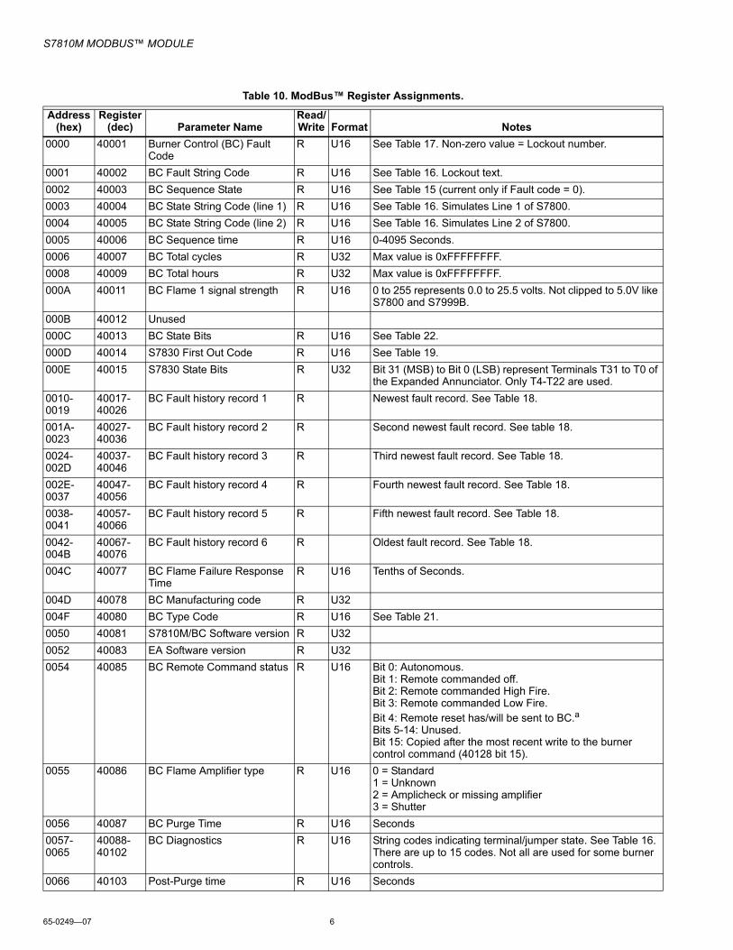
A second communications port supports RS-485 communications using ModBus™ protocol. The following tables provide ModBus™ mapping information.
Table 10 provides register mapping. It identifies the mapping of the 7800 SERIES parameters to ModBus™ registers. These codes are transmitted by the relay modules and the S7830 Expanded Annunciator.
Function CodesSupported function codes of ModBus™ Protocol Reference Guide (PI-MBUS-300 Rev. J) are 3, 4, 6, and 17. Function codes 3 and 4 are treated the same by the S7810M. Two registers need to be read when the data format is a U32 value (4 bytes); if both registers are not read, then a data value of 0 (zero) is returned. U32 values are in little endian format. The maximum number of addresses that can be queried is 127 (0x7F) for query messages 3 and 4.
Tables 3 through 7 provide information on the function codes.
NOTE: All Query and Response cells below are 1 byte.
Signal S7810M TerminalControlBus™ Data + 1ControlBus™ Data - 2Common• ControlBus™ Common• +13 Vdc Common• Remote Reset Common
3
+13 Vdc 4Remote Reset 5ModBus™ Common 6ModBus™ Data + 7ModBus™ Data - 8
Table 2. Explanation of MODE LED light patternsLED Code/Behavior Pulse Period Interval Meaning
Always OFF OFF Not powered or device failure.
Always ON ON S7810M device failure.
Mostly ON with 1 blink
50 ms (OFF) 1 second Both ControlBus™ and ModBus™ are active
Mostly OFF with 1 flash
50 ms (ON) 3.85 seconds
ControlBus™ is active, and ModBus™ is not active.
Mostly OFF with 2 pulses
2 x (200 ms ON, 200 ms OFF)
1.75 seconds
Program CRC error.
Mostly OFF with 3 pulses
3 x (200 ms ON, 200 ms OFF)
2.15 seconds
No ControlBus™ signal from the Burner Control

S7810M MODBUS™ MODULE
5 65-0249—07
Table 3. Query Message Format for Function Codes 3 and 4.
Table 4. Response Message Format for Function Codes 3 and 4.
Table 5. Query Message Format for Function Code 6 (Broadcast is supported by using a slave address of 00).
Table 6. Response Message Format for Function Code 6 (There is no response if the query was broadcast.)
Table 7. Query Message Format for Function Code 17.
NOTE: See Table 20 for function code 17 response format.
Table 8. Exception Response Message Format.
Table 9. Exception Codes.
Device Address and Baud RateAssign each S7810M in the system a unique address by setting the MODBUS ADDRESS switches on the bottom of the device to the correct number. See Fig. 4. Only RTU communications with 1 Start Bit, 8 Data Bits, 1 Stop Bit and no parity is supported.
NOTE: Assign a device address number from 01 to 99. 00 is not an acceptable address number and will not work.
The default baud rate is 9600. To change the baud rate to 19.2K, use a needlenose pliers to remove the jumper. See Fig. 4.
IMPORTANT:S7999B requires a baud rate of 19.2K.
Fig. 4. 7810M Address Switches and Baud Rate Jumper.
NOTE: In Tables 10, 15 and 19: Line 1 and Line 2 refer to the two lines of text on the S7800 Keyboard Display Mod-ule. In Tables 15, 17 and 19: The String Code column references Table 16, String Codes. In Table 15: The Burner Control State Bits column references Table 22, Burner Control State Bits.
Slave AddressFunction
CodeStarting
Address HighStarting
Address LowNumber of
Addresses HighNumber of
Addresses Low CRC CRC01 03 00 0A 00 01 A4 08
Slave Address Function Code Byte Count Data High Data Low CRC CRC01 03 02 00 22 38 5D
Slave Address
Function Code
Starting Address High
Starting Address Low
Preset Data High
Preset Data Low CRC CRC
01 06 00 7F 00 04 B9 D1
Slave Address
Function Code
Starting Address High
Starting Address Low
Preset Data High
Preset Data Low CRC CRC
01 06 00 7F 00 04 B9 D1
Slave Address
Function Code CRC CRC
03 11 C1 4C
Slave Address
Function Code + 80h
Exception Code
CRC CRC
Exception Code Definition Description
01 Illegal Function
An illegal function as requested. Only 3, 4, 6 and 17 are supported.
02 Illegal Data Address
Too many bytes requested, address is out of range, register is read only, or the number of address requested is past the last register.
03 Illegal Data Value
The “Preset Data” from function code 6 is invalid/out of range.
3 42
1 5
89 7
60
3 42
1 5
89 7
60
10'S 1'SBAUDRATE
MODBUSADDRESS
OUT19.2K
IN9600
56
7
3 42
1
890 SCREWDRIVERNEEDLENOSE
PLIERS
M17650
S7810M MODBUS™ MODULE
65-0249—07 6
Table 10. ModBus™ Register Assignments.
Address (hex)
Register(dec) Parameter Name
Read/Write Format Notes
0000 40001 Burner Control (BC) Fault Code
R U16 See Table 17. Non-zero value = Lockout number.
0001 40002 BC Fault String Code R U16 See Table 16. Lockout text.0002 40003 BC Sequence State R U16 See Table 15 (current only if Fault code = 0).0003 40004 BC State String Code (line 1) R U16 See Table 16. Simulates Line 1 of S7800.0004 40005 BC State String Code (line 2) R U16 See Table 16. Simulates Line 2 of S7800.0005 40006 BC Sequence time R U16 0-4095 Seconds.0006 40007 BC Total cycles R U32 Max value is 0xFFFFFFFF.0008 40009 BC Total hours R U32 Max value is 0xFFFFFFFF.000A 40011 BC Flame 1 signal strength R U16 0 to 255 represents 0.0 to 25.5 volts. Not clipped to 5.0V like
S7800 and S7999B.000B 40012 Unused000C 40013 BC State Bits R U16 See Table 22.000D 40014 S7830 First Out Code R U16 See Table 19.000E 40015 S7830 State Bits R U32 Bit 31 (MSB) to Bit 0 (LSB) represent Terminals T31 to T0 of
the Expanded Annunciator. Only T4-T22 are used.0010-0019
40017-40026
BC Fault history record 1 R Newest fault record. See Table 18.
001A-0023
40027-40036
BC Fault history record 2 R Second newest fault record. See table 18.
0024-002D
40037-40046
BC Fault history record 3 R Third newest fault record. See Table 18.
002E-0037
40047-40056
BC Fault history record 4 R Fourth newest fault record. See Table 18.
0038-0041
40057-40066
BC Fault history record 5 R Fifth newest fault record. See Table 18.
0042-004B
40067-40076
BC Fault history record 6 R Oldest fault record. See Table 18.
004C 40077 BC Flame Failure Response Time
R U16 Tenths of Seconds.
004D 40078 BC Manufacturing code R U32004F 40080 BC Type Code R U16 See Table 21.0050 40081 S7810M/BC Software version R U320052 40083 EA Software version R U320054 40085 BC Remote Command status R U16 Bit 0: Autonomous.
Bit 1: Remote commanded off.Bit 2: Remote commanded High Fire.Bit 3: Remote commanded Low Fire.Bit 4: Remote reset has/will be sent to BC.aBits 5-14: Unused.Bit 15: Copied after the most recent write to the burner control command (40128 bit 15).
0055 40086 BC Flame Amplifier type R U16 0 = Standard1 = Unknown2 = Amplicheck or missing amplifier3 = Shutter
0056 40087 BC Purge Time R U16 Seconds0057-0065
40088-40102
BC Diagnostics R U16 String codes indicating terminal/jumper state. See Table 16. There are up to 15 codes. Not all are used for some burner controls.
0066 40103 Post-Purge time R U16 Seconds

S7810M MODBUS™ MODULE
7 65-0249—07
a Remote Reset command not accepted by S7810M1029.
0067 40104 Valve Proving Mode R U16 0 = Valve Proving is not enabled1 = Enabled before Run2 = Enabled after Run3 = Enabled before and after Run4 = Enabled split half before and half after Run
0068 40105 Valve Proving option R U16 1 = Uncommissioned2 = Commissioned
0069 40106 Valve Proving time R U16 Seconds0066-007E
40103-40127
Unused
007F 40128 BC Remote Command R/W U16 Only one bit in the LSByte must be set, with the exception of bit 15:Bit 0 = Revert to autonomous operation.Bit 1 = Don’t fire, remain off.Bit 2 = Go to Hi Fire during Run.Bit 3 = Go to Lo Fire during Run.Bit 4 = Remote reset.aBits 5-7 must be 0.Bits 8-14 are ignored.Bit 15: Copied to the control status register. The remote control status register can be used to verify operation of the command.
NOTE: Bits 1-3 must be refreshed at least every 120 sec-onds, but not more than once a second, for the burner control to remain in the commanded state.
Table 10. ModBus™ Register Assignments. (Continued)
Address (hex)
Register(dec) Parameter Name
Read/Write Format Notes
Table 11. ModBus™ R7999 Register Assignments.
Address (hex)
Register (dec) Parameter Name Format Notes
0080 40129 R7999 reserved U16 Not used—always zero.0081 40130 R7999 program mode U16 0—Initiate State.
1—Normal Operation.2—Alarm Initiate State.3—Lockout.4—Not Configured.5—Factory Test.6—Low Voltage.7—Commissioning.8—Reset.
0082 40131 R7999 fault code U16 See Table 26.0083 40132 R7999 operational
statusU16 00—Standby Hold.
01—Standby Stop Position.02—Standby Main Valve.03—Standby Low Fire Main Valve.04—Standby Purge.05—Fault 1.06—Standby Hi Fire Main Valve.07—Fault 2.08—Processing Demand.09—Light Off.10—Modulate.11—Light Off Low Fire Main Valve.12—Purge.13—Fault 3.14—Purge Main Valve.15—Fault 4.16—Initialize.17—Post Purge.

S7810M MODBUS™ MODULE
65-0249—07 8
0084 40133 R7999 air position U16 0-40950085 40134 R7999 active fuel
positionU16 0-4095
0086 40135 R7999 FGR position U16 0-40950087 40136 R7999 fuel ID U16 0 = Fuel 1
1 = Fuel 20088-0089
40137-40138
R7999 cycles U32 0—1,000,000Same as register 40410.
008A 40139 R7999 diagnostic bits. U16 Bit Meaning15—LCO state14—HFP state13—LFP state12—ALARM state11—LCI state10—HF state 9—MV state 8—LF state 7—LCO Relay Drive 2 feedback 6—LCO Relay Drive 1 feedback 5—LCM state 4—AUTO/MAN select 3—Selected Fuel 2—Fuel Select 2 Input 1—Fuel Select 1 Input 0—Hold State (Bit will be set On if Aux Input is in a hold condition or disabled)
008B 40140 R7999 firing rate input U16 0-255 = 0-21.1 mA.008C 40141 R7999 manual pot input U16 0-255 = 2.1-44.1 mA.008D 40142 R7999 auxiliary input U16 0-255 = 0-21.1 mA.008E 40143 Unused008F 40144 R7999 Hold U16 Same as register 40139 bit 00090-009E
40145-40159
Unused
Table 12. ModBus™ R7999 Register Assignments.
Address (hex) Register (dec) Parameter Name Bytes Notes
009F 40160 R7999 Message Counter Format—U16Bits 0-2 = The Buffer Index of the oldest information from the R7999. (Incremented by the BC status message once a second.)Bits 0-15 = A counter synchronized with R7999 messages.
00A0-00A5 40161-40166 R7999 buffer # 0 0-11 These buffers store an 8-second history of status data from the R7999. The oldest buffer is indicated by register 40160, bits 0-2. This scheme forms a circular buffer of information. A buffer will contain all zeros if the S7810M received bad data for the buffer time slot. See Table 25 for interpretation of bytes 0-11.
00A6-00AB 40167-40172 R7999 buffer # 1 0-1100AC-00B1 40173-40178 R7999 buffer # 2 0-1100B2-00B7 40179-40184 R7999 buffer # 3 0-1100B8-00BD 40185-40190 R7999 buffer # 4 0-1100BE-00C3 40191-40196 R7999 buffer # 5 0-1100C4-00C9 40197-40202 R7999 buffer # 6 0-1100CA-00CF 40203-40208 R7999 buffer # 7 0-11
Table 11. ModBus™ R7999 Register Assignments. (Continued)
Address (hex)
Register (dec) Parameter Name Format Notes

S7810M MODBUS™ MODULE
9 65-0249—07
Table 13. ModBus™ R7999 Register Assignments.
Address (hex)
Register (dec) Parameter Name Format Notes
00D0-015F
40209-40352
R7999 Profile See Table 23.
0160 40353 Fuel 1 closed endpoint U16 0-40950161 40354 Fuel 1 open endpoint U16 0-40950162 40355 Fuel 2 closed endpoint U16 0-40950163 40356 Fuel 2 open endpoint U16 0-40950164 40357 Inactive motor position U16 0-40950165 40358 Registers 40353-40357 are current U16 0-10166 40359 Air closed endpoint position U16 0-40950167 40360 Air open endpoint position U16 0-40950168 40361 FGR closed endpoint position U16 0-40950169 40362 FGR open endpoint position U16 0-4095016A 40363 Unused U16016B 40364 Registers 40359-40363 are current U16 0-1016C-018F
40365-40400
R7999 Fault Information Ref. Table 24.
0190 40401 Air Total Resistance U16 0-4095. Air actuator feedback pot resistance.0191 40402 Fuel 1 Total Resistance U16 0-4095. Fuel 1 actuator feedback pot resistance.0192 40403 Fuel 2 Total Resistance U16 0-4095. Fuel 2 actuator feedback pot resistance.0193 40404 FGR Total Resistance U16 0-4095. FGR actuator feedback pot resistance.0194 40405 Air Resistance Change U16 0-4095. Bit 15 is a sign flag. 1 = negative, 0 = positive.0195 40406 Registers 40401-40405 are current U16 0-10196 40407 Fuel 1 Resistance Change U16 0-4095. Bit 15 is a sign flag. 1 = negative, 0 = positive.0197 40408 Fuel 2 Resistance Change U16 0-4095. Bit 15 is a sign flag. 1 = negative, 0 = positive.0198 40409 FGR Resistance Change U16 0-4095. Bit 15 is a sign flag. 1 = negative, 0 = positive.0199 40410-
40411LCO Cycle Count U32 0-1,000,000
Same as 40137019B 40412 Registers 40407-40411 are current U16 0-1019C 40413 Air Purge Preset Position U16 0-4095019D 40414 Fuel Purge Preset Position U16 0-4095019E 40415 FGR Purge Preset Position U16 0-4095019F 40416 Air Lightoff Preset Position U16 0-409501A0 40417 Fuel Lightoff Preset Position U16 0-409501A1 40418 Registers 40413-40417 are current U16 0-101A2 40419 Lightoff Preset FGR U16 0-409501A3 40420 Air Standby Position U16 0-409501A4 40421 Fuel Standby Position U16 0-409501A5 40422 FGR Standby Position U16 0-409501A6 40423 Non-Selected Fuel Standby
PositionU16 0-4095
01A7 40424 Registers 40419-40423 are current U16 0-101A8 40425 Number of Profile Points U16H 0-23
Major Software Revision U16L01A9 40426 Minor Software Revision U16H
Software Version Code U16L

S7810M MODBUS™ MODULE
65-0249—07 10
01AA 40427 R7999 ControlBus™ revision U16H Bits 0-3 FlameNet™ and R7999 display.R7999 Compatibility Code for ZM7999
U16L
01AB 40428 R7999 Software Build Code U16 0x0000-0xFFFF01AC 40429 Abort Code U16H 0-255
Abort Code Count U16L 0-25501AD 40430 Registers 40425-40429 are current U16 0-101AE 40431 Low Fire Hold Configuration U16H 0—Disabled (Not configured—See note in register 40139)
1—Low Fire Hold (Position the FGR, Air and Fuel actuators at the Light Off Position).2—Modulate with FGR closed (FGR closed, Air and fuel modulating).3—Low Fire Hold with FGR closed (FGR closed, Air and Fuel at Light Off Position).
Configuration Options U16L If a Bit = 1, then the option is configured.Bit 0: FGR is set to follow the profile (curve) during purge.Bit 1: Maximum Firing rate is controlled by the Manual Firing Rate input.Bits 2-15: Unused.
01AF 40432 Min Auxiliary Temperature U16 0x0000-0xFFFF. Subtract 40 to get the actual value.01B0 40433 Max Auxiliary Temperature U16 0x0000-0xFFFF. Subtract 40 to get the actual value.01B1 40434 Auxiliary Release Temperature
CountsU16 Release the Low Fire Hold condition and allow Modulation
after the Aux. temperature reaches this temperature or higher. See Note 5.
01B2 40435 Auxiliary Enforce Temperature Counts
U16 Initiate a Hold condition when the Aux. temperature reaches this temperature or lower. See Note 5.
01B3 40436 Registers 40431-40435 are current U16 0-101B4-01B5
40437-40438
Running Time in Hours U32
01B6 40439 Running Time in Minutes U16HUnused U16L
01B7-01B8
40440-40441
Unused U32
01B9 40442 Registers 40437-40440 are current U16 0-101BA 40443 Device Data Ready U16 Device data was properly received by S7810M.
Bit(s) Device0 RM78XX1 R79992 S7830 Expanded Annunciator3 EC78XX4-15 Unused
01BB 40444 S7810M Device Compatibility with Current Software Revision
S7810M Software Revision Compatibility with Legacy Software Revisions.
U16 Device is compatible with the S7810M versionBit Device0 RM78XX1 R79992 S7830 Expanded Annunciator3 EC78XX4-7 Unused
Used for indication of S7810M revision compatibility.Bit(s) Compatible with:8 Series 29-15 Future
Table 13. ModBus™ R7999 Register Assignments. (Continued)
Address (hex)
Register (dec) Parameter Name Format Notes
S7810M MODBUS™ MODULE
11 65-0249—07
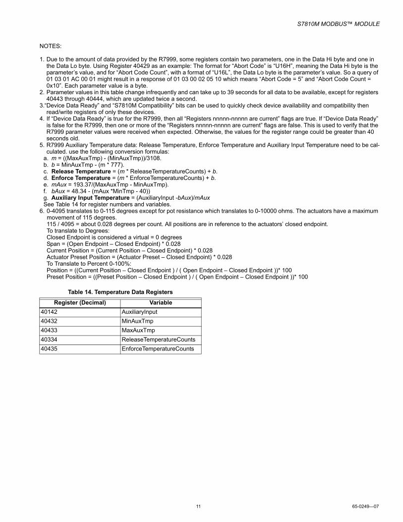
NOTES:
1. Due to the amount of data provided by the R7999, some registers contain two parameters, one in the Data Hi byte and one in the Data Lo byte. Using Register 40429 as an example: The format for “Abort Code” is “U16H”, meaning the Data Hi byte is the parameter’s value, and for “Abort Code Count”, with a format of “U16L”, the Data Lo byte is the parameter’s value. So a query of 01 03 01 AC 00 01 might result in a response of 01 03 00 02 05 10 which means “Abort Code = 5” and “Abort Code Count = 0x10”. Each parameter value is a byte.
2. Parameter values in this table change infrequently and can take up to 39 seconds for all data to be available, except for registers 40443 through 40444, which are updated twice a second.
3.“Device Data Ready” and “S7810M Compatibility” bits can be used to quickly check device availability and compatibility then read/write registers of only these devices.
4. If “Device Data Ready” is true for the R7999, then all “Registers nnnnn-nnnnn are current” flags are true. If “Device Data Ready” is false for the R7999, then one or more of the “Registers nnnnn-nnnnn are current” flags are false. This is used to verify that the R7999 parameter values were received when expected. Otherwise, the values for the register range could be greater than 40 seconds old.
5. R7999 Auxiliary Temperature data: Release Temperature, Enforce Temperature and Auxiliary Input Temperature need to be cal-culated. use the following conversion formulas:
a. m = ((MaxAuxTmp) - (MinAuxTmp))/3108.b. b = MinAuxTmp - (m * 777).c. Release Temperature = (m * ReleaseTemperatureCounts) + b.d. Enforce Temperature = (m * EnforceTemperatureCounts) + b.e. mAux = 193.37/(MaxAuxTmp - MinAuxTmp).f. bAux = 48.34 - (mAux *MinTmp - 40))g. Auxiliary Input Temperature = (AuxiliaryInput -bAux)/mAuxSee Table 14 for register numbers and variables.
6. 0-4095 translates to 0-115 degrees except for pot resistance which translates to 0-10000 ohms. The actuators have a maximum movement of 115 degrees.115 / 4095 = about 0.028 degrees per count. All positions are in reference to the actuators’ closed endpoint.To translate to Degrees:Closed Endpoint is considered a virtual = 0 degreesSpan = (Open Endpoint – Closed Endpoint) * 0.028Current Position = (Current Position – Closed Endpoint) * 0.028Actuator Preset Position = (Actuator Preset – Closed Endpoint) * 0.028To Translate to Percent 0-100%: Position = ((Current Position – Closed Endpoint ) / ( Open Endpoint – Closed Endpoint ))* 100 Preset Position = ((Preset Position – Closed Endpoint ) / ( Open Endpoint – Closed Endpoint ))* 100
Table 14. Temperature Data Registers
Register (Decimal) Variable40142 AuxiliaryInput40432 MinAuxTmp40433 MaxAuxTmp40334 ReleaseTemperatureCounts40435 EnforceTemperatureCounts

S7810M MODBUS™ MODULE
65-0249—07 12
7800 SERIES Sequence State CodesSequence state codes are provided by the Burner Control. Each code is translated into two string codes for displaying an associated message in two lines. Each code is also translated into burner control state bits which may be used to generate and control system diagrams on an operator interface.
The Sequence State Codes shown in Table 15 are current only if the Fault Code has a value of zero. If the Fault Code is non-zero, the sequence state field contains the sequence state code when the lockout occurred.
The codes can also be retrieved from registers 40004, 40005, and 40013.
Table 15. 7800 SERIES Sequence State Codes and Associated register code values.
Register 40003
7800 SERIES Sequence
State
String Code
Uses mm:ss
Burner Control
State BitsLine 1 Line 2
Fault code not zero
LOCKOUT 52 Table 17
8000h
0 UNUSED HISTORY
0 0 0000h
1 INITIATE 48 0 0001h2 INITIATE HOLD:
AC FREQUENCY/NOISE
49 8 4001h
3 INITIATE HOLD:AC LINE DROPOUT
49 9 4001h
4 INITIATE HOLD:AC FREQUENCY
49 7 4001h
5 INITIATE HOLD:LOW LINE VOLTAGE
49 60 4001h
6 STANDBY 103 0 0002h7 STANDBY
HOLD: REMREMOTE CONTROL
104 94 4002h
8 STANDBY HOLD:START SWITCH
104 106 4002h
9 STANDBY HOLD: F/GFLAME DETECTED
104 35 4002h
10 STANDBY HOLD: T20PREIGNITION
104 86 4002h
11 STANDBY HOLD: T7RUNNING INTERLOCK
104 101 4002h
12 STANDBY HOLD: T7LOCKOUT INTERLOCK
104 54 4002h
13 STANDBY HOLD:AIRFLOW SWITCH
104 13 4002h
14 PURGE HOLD: T19HIGH FIRE SWITCH
93 40 4004h
15 PURGE DELAY: T19HIGH FIRE JUMPRD
89 39 4004h
16 PURGE HOLD: TESTRUN/TEST SWITCH
93 98 4004h
17 PURGE DELAY: T18LOW FIRE JUMPRD
89 56 4004h
18 PURGE HOLD: F/GFLAME DETECTED
93 35 4004h
19 PURGE 87 0 0004h20 PURGE HOLD:
T18LOW FIRE SWITCH
93 58 4004h
21 PURGE HOLD: T7Running Interlock
93 101 4004h
22 PURGE HOLD: LOCKOUT INTERLOCK
93 54 4004h
23 PURGE HOLD: AIRFLOW SWITCH
93 13 4004h
24 PURGE HOLD: START SWITCH
93 106 4004h
25 PILOT IGN 78 0 0008h26 PILOT HOLD:
TESTRUN/TEST SWITCH
77 98 4008h
27 PILOT HOLD: START SWITCH
77 106 4008h
28 MAIN IGN 66 0 0010h
Table 15. 7800 SERIES Sequence State Codes and Associated register code values. (Continued)
Register 40003
7800 SERIES Sequence
State
String Code
Uses mm:ss
Burner Control
State BitsLine 1 Line 2

S7810M MODBUS™ MODULE
13 65-0249—07
29 MAIN IG HOLD: MANUAL-OPEN SWITCH
67 72 4010h
30 RUN 95 0 0020h31 RUN PV HOLD:
LOW FIRE SWITCH
96 58 4020h
32 PVHOLD IGN 77 46 4008h33 PV HOLD:
PV HOLD SWITCH
77 45 4008h
34 RUN/LOWFIRE: TESTRUN/TEST SWITCH
97 98 4020h
35 POSTPURGE 83 0 0040h36 STATE
UNKNOWN31 0 0000h
37 RESET/ALARM TEST
111 0 6000h
38 SAFETY START 102 105 4002h39 SAFETY1-1 102 2 0008h40 SAFETY1-2 102 3 0008h41 SAFETY1-3 102 4 0008h42 SAFETY1-4 102 5 0008h43 SAFETY1-5 102 6 0008h44 Blank 0 0 A000h45 PREIGNITION 84 0 0080h46 SAFETY 1 102 1 0008h47 PILOT STAB. 79 0 0008h48 MAIN TRIAL 68 0 0010h49 MAIN TRIAL 68 0 0010h50 STANDBY
HOLD:RUN/TEST SWITCH
104 98 4002h
51 STATE 51 31 0 A000h52 STATE 52 31 0 A000h53 SAFETY 1:
RUN/TEST SWITCH
102 98 4008h
54 STATE 54 31 0 A000h55 STANDBY
HOLD:PURGE FAN SWITCH
104 92 4002h
56 STATE 56 31 0 A000h57 PURGE HOLD:
PURGE FAN SWITCH
93 92 4004h
Table 15. 7800 SERIES Sequence State Codes and Associated register code values. (Continued)
Register 40003
7800 SERIES Sequence
State
String Code
Uses mm:ss
Burner Control
State BitsLine 1 Line 2
58 STANDBY HOLD FLAME DETECTED
104 35 4002h
59 STANDBY HOLD COMB. PRESSURE
104 26 4002h
60 VP START 210 0 0100h61 VP MV2 ON 211 0 0100h62 VP LOW DLY 212 0 4100h63 VP LOW TST 213 0 0100h64 VP MV1 ON 214 0 0100h65 VP HIGH DLY 215 0 4100h66 VP HIGH TST 216 0 0100h67 INITIATE HOLD:
ACAC PHASE ERROR
49 10 4001h
68 STANDBY HOLD:PRE-IGNITION ILK
104 85 4002h
69 SETUP NEEDED
217 0 A000h
70 STATE 70 31 0 A000h71 BURNER OFF:
T6BURNER SWITCH
22 23 4002h
72 STANDBY HOLD: T6 (EA) HOLD MSG
184 30 4002h
73 STANDBY HOLD: (EA) CIRCUIT FAULT
184 25 4002h
74 STANDBY HOLD (EA)
184 Varies 4002h
75 PURGE HOLD (EA)
185 Varies 4004h
76 Unused 0 Varies 0000h77 Unused 0 Varies 0000h78 Unused 0 Varies 0000h79 STANDBY
HOLD (EA)184 Varies 4002h
80 STANDBY HOLD (EA)
184 Varies 4002h
81 STANDBY HOLD (EA): VALVE CLOSURE
184 109 4002h
82 STANDBY HOLD (EA) OTHER PII
184 75 4002h
Table 15. 7800 SERIES Sequence State Codes and Associated register code values. (Continued)
Register 40003
7800 SERIES Sequence
State
String Code
Uses mm:ss
Burner Control
State BitsLine 1 Line 2

S7810M MODBUS™ MODULE
65-0249—07 14
7800 SERIES String CodesTable 16 contains a listing of all string codes provided by the S7810M. The associated string is not implemented in the S7810M; it is a string equivalent to that displayed on the S7800 Keyboard Display Module or similar device.
Table 16. 7800 SERIES String codes.
String Code String0 (blank)1 12 1-13 1-24 1-35 1-46 1-57 AC FREQUENCY8 AC Frequency/Noise9 AC LINE DROPOUT10 AC PHASE11 ACCESSORY FAULT12 AIRFLOW SW. ON13 AIRFLOW SWITCH14 ATOMIZING SW15 AUX INTERLOCK #416 AUX INTERLOCK #517 AUX LIMIT #118 AUX LIMIT #219 AUX LIMIT #320 BLOCK INTAKE21 BOTH FUELS SELECT22 BURNER OFF23 BURNER SWITCH24 CALL SERVICE25 CIRCUIT FAULT26 COMB. PRESSURE27 CONTROL ON28 DELAYED MV ON29 DEVICE SPECIFIC30 EA HOLD MESSAGE31 UNKNOWN STATE32 FLAME AMP TYPE33 FLAME AMP/SHUTR34 FLAME AMPLIFIER35 FLAME DETECTED36 FLAME TOO STRONG37 FLAME-OUT TIMER38 FUEL SELECT OFF39 HIGH FIRE JUMPERED40 HIGH FIRE SWITCH41 HIGH GAS PRESSURE
42 HIGH LIMIT43 HIGH OIL PRESSURE44 HIGH OIL TEMP45 HOLD SWITCH46 IGNITION47 IGNITION ON48 INITIATE49 INITIATE HOLD50 JUMPERS CHANGED51 JUMPERS WRONG52 LOCKOUT53 LOCKOUT ILK ON54 LOCKOUT INTERLOCK55 LOCKOUT SWITCH56 LOW FIRE JUMPERED57 LOW FIRE SW OFF58 LOW FIRE SWITCH59 LOW GAS PRESSURE60 LOW LINE VOLTAGE61 LOW OIL PRESSURE62 LOW OIL TEMP63 LWCO64 MAIN FLAME FAIL65 MAIN FLAME IGN.66 MAIN IGN67 MAIN IGN HOLD68 MAIN TRIAL69 MAIN VALVE ON70 MAN-OPEN SW. OFF71 MAN-OPEN SW. ON72 MAN-OPEN SW.73 NO PURGE CARD74 OTHER INTERLOCKS75 OTHER PREIGN ILK76 PILOT FLAME FAIL77 PILOT HOLD78 PILOT IGN79 PILOT STABILIZE80 PILOT VALVE 1 ON81 PILOT VALVE 2 ON82 POOR FLAME SENSOR83 POSTPURGE84 PREIGNITION85 PREIGNITION ILK86 PREIGNITION87 PURGE88 PURGE CARD ERROR
Table 16. 7800 SERIES String codes. (Continued)
String Code String

S7810M MODBUS™ MODULE
15 65-0249—07
89 PURGE DELAY90 PURGE FAN SW OFF91 PURGE FAN SW ON92 PURGE FAN SWITCH93 PURGE HOLD94 REMOTE CONTROL95 RUN96 RUN HOLD97 RUN/LOWFIRE98 RUN/TEST SWITCH99 RUNNING ILK100 RUNNING ILK ON101 RUNNING INTERLOCK102 SAFETY 103 STANDBY104 STANDBY HOLD105 START106 START SWITCH107 START SWITCH ON108 TEST STATE109 VALVE CLOSURE110 ALL SWITCHES ON111 RESET/ALARM TEST112 Run/Test Switch RUN113 Run/Test Switch TEST114 Operator Control T6 = 0115 Operator Control T6 = 1116 Interlock T7 = 0117 Interlock T7 = 1118 Airflow Interlock T7 = 0119 Airflow Interlock T7 = 1120 Block Intake T7 = 0121 Block Intake T7 = 1122 Valve T8 = 0123 Valve T8 = 1124 Intrptd PV T8 = 0125 Intrptd PV T8 = 1126 Main Valve T9 = 0 127 Main Valve T9 = 1128 Ignition T10 = 0129 Ignition T10 = 1130 PV Hold T16 = 0131 PVHold T16 = 1132 Input A T16 = 0133 Input A T16 = 1134 ManOpenSw T17 = 0135 ManOpenSw T17 = 1
Table 16. 7800 SERIES String codes. (Continued)
String Code String136 Input B T17 = 0137 Input B T17 = 1138 PreIgn ILK T17 = 0139 PreIgn ILK T17 = 1140 LowFire Sw T18 = 0141 LowFire Sw T18 = 1142 Purge Fan T18 = 0143 Purge Fan T18 = 1144 HighFire Sw T19 = 0145 HighFire Sw T19 = 1146 PreIgn ILK T20 = 0147 PreIgn ILK T20 = 1148 Lockout Inp T20 = 0149 Lockout Inp T20 = 1150 Comb Press T20 = 0151 Comb Press T20 = 1152 Valv/Start T21 = 0153 Valv/Start T21 = 1154 Intmitt PV T21 = 0155 Intmitt PV T21 = 1156 Terminal T6 = 0157 Terminal T6 = 1158 Terminal T7 = 0159 Terminal T7 = 1160 Terminal T8 = 0161 Terminal T8 = 1162 Terminal T9 = 0163 Terminal T9 = 1164 Terminal T10 = 0165 Terminal T10 = 1166 Terminal T16 = 0167 Terminal T16 = 1168 Terminal T17 = 0169 Terminal T17 = 1170 Terminal T18 = 0171 Terminal T18 = 1172 Terminal T19 = 0173 Terminal T19 = 1174 Terminal T20 = 0175 Terminal T20 = 1176 Terminal T21 = 0177 Terminal T21 = 1178 Jumper 1 Intact179 Jumper 1 Clipped180 Jumper 2 Intact181 Jumper 2 Clipped182 Jumper 3 Intact
Table 16. 7800 SERIES String codes. (Continued)
String Code String

S7810M MODBUS™ MODULE
65-0249—07 16
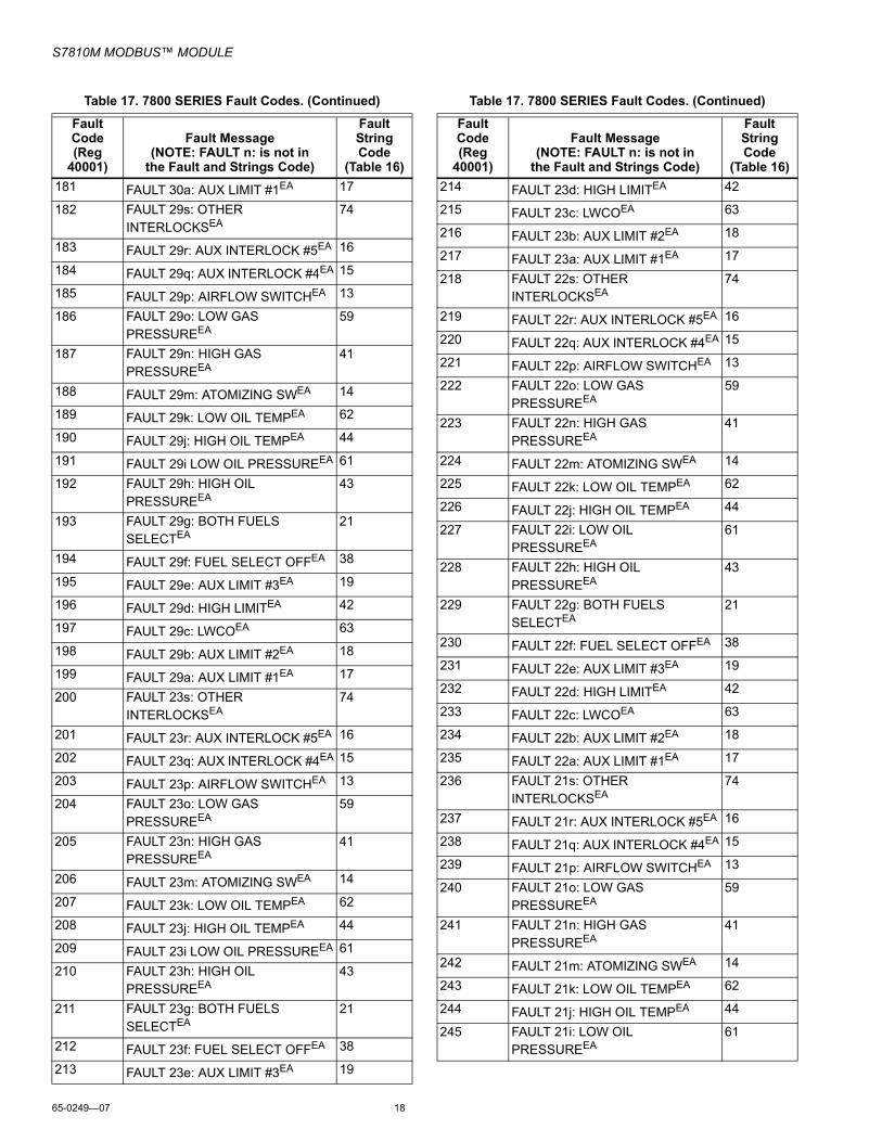
7800 SERIES Fault CodesTable 17 is a complete list of fault codes that may appear in the fault code register. The Fault String Code register will contain the corresponding String code identified in the table.183 Jumper 3 Clipped)
184 STANDBY HOLD (EA)185 PURGE HOLD (EA)186 PILOT HOLD (EA)187 MAIN IG HOLD (EA)188 RUN HOLD (EA)189 POSTPURGE HOLD (EA)190 PREIGNITION HOLD (EA)191 -SKIPPED-192 DEMAND T6 = 0193 DEMAND T6 = 1194 PILOT VALVE T8 = 0195 PILOT VALVE T8 = 1196 INTERMIT PV T8 = 0197 INTERMIT PV T8 = 1198 MAIN VALVE1 T9 = 0199 MAIN VALVE1 T9 = 1200 VP SWITCH T16 = 0201 VP SWITCH T16 = 1202 MAIN VALVE2 T17 = 0203 MAIN VALVE2 T17 = 1204 INTRUPTD PV T21 = 0205 INTRUPTD PV T21 = 1206 DELAYED MV T21 = 0207 DELAYED MV T21 = 1208 START SW T21 = 0209 START SW T21 = 1210 VP START211 VP MV2 ON212 VP LOW DLY213 VP LOW TST214 VP MV1 ON215 VP HIGH DLY216 VP HIGH TST217 VP SETUP NEEDED218 MAIN VALVE 1 OFF219 MAIN VALVE 2 OFF220 MAIN VALVE 1 ON221 MAIN VALVE 2 ON222 VPS OFF223 VPS ON224 HIGH CYCLE RATE
Table 16. 7800 SERIES String codes. (Continued)
String Code String
Table 17. 7800 SERIES Fault Codes.
Fault Code(Reg
40001)
Fault Message(NOTE: FAULT n: is not in
the Fault and Strings Code)
Fault String Code
(Table 16)0 Blank (no fault) 01 FAULT 1: NO PURGE CARD 732 FAULT 2: AC FREQUENCY/NOISE 83 FAULT 3: AC LINE DROPOUT 94 FAULT 4: AC FREQUENCY 75 FAULT 5: LOW LINE VOLTAGE 606 FAULT 6: PURGE CARD ERROR 887 FAULT 7: FLAME AMPLIFIER 348 FAULT 8: FLAME AMP/SHUTR 339 FAULT 9: FLAME DETECTED 3510 FAULT 10: PREIGNITION ILK 8511 FAULT 11: RUNNING ILK ON 10012 FAULT 12: LOCKOUT ILK ON 5313 FAULT 13: AIRFLOW SW. ON 1214 FAULT 14: HIGH FIRE SWITCH 4015 FAULT 15: FLAME DETECTED 3516 FAULT 16: FLAME-OUT TIMER 3717 FAULT 17: MAIN FLAME FAIL 6418 FAULT 18: FLAME DETECTED 3519 FAULT 19: MAIN FLAME IGN. 6520 FAULT 20: LOW FIRE SW OFF 5721 FAULT 21: RUNNING ILK 9922 FAULT 22: LOCKOUT ILK 5423 FAULT 23: AIRFLOW SWITCH 1324 FAULT 24: CALL SERVICE 2425 FAULT 25: CALL SERVICE 2426 FAULT 26: MAN-OPEN SW. OFF 7027 FAULT 27: START SWITCH ON 7128 FAULT 28: PILOT FLAME FAIL 7629 FAULT 29: LOCKOUT ILK 5430 FAULT 30: RUNNING ILK 10131 FAULT 31: LOW FIRE SW OFF 5732 FAULT 32: AIRFLOW SWITCH 1333 FAULT 33: PREIGNITION ILK 8534 FAULT 34: CONTROL ON 2735 FAULT 35: CALL SERVICE 2436 FAULT 36: CALL SERVICE 2437 FAULT 37: CALL SERVICE 2438 FAULT 38: CALL SERVICE 2439 FAULT 39: CALL SERVICE 2440 FAULT 40: CALL SERVICE 24

S7810M MODBUS™ MODULE
17 65-0249—07
41 FAULT 41: MAIN VALVE ON 6942 FAULT 42: PILOT VALVE 1 ON 8043 FAULT 43: IGNITION ON 4744 FAULT 44: PILOT VALVE 2 ON 8145 FAULT 45: LOW FIRE SW OFF 5746 FAULT 46: FLAME AMP TYPE 3247 FAULT 47: JUMPERS CHANGED 5048 FAULT 48: DELAYED MV ON 2849 FAULT 49: MAN-OPEN SW. ON 7150 FAULT 50: JUMPERS WRONG 5151 FAULT 51: FLAME TOO STRONG 3652 FAULT 52: CALL SERVICE 2453 FAULT 53: LOCKOUT SWITCH 5554 FAULT 54: COMB. PRESSURE 2655 FAULT 55: PURGE FAN SW ON 9156 FAULT 56: BLOCK INTAKE 2057 FAULT 57: PURGE FAN SW OFF 9058 FAULT 58: COMB.PRESSURE/
FLAME26
59 FAULT 59: CALL SERVICE 2460 FAULT 60: CALL SERVICE 2461 FAULT 61: MV1 OFF 21862 FAULT 62: MV2 OFF 21963 FAULT 63: MV1 ON 22064 FAULT 64: MV2 ON 22165 FAULT 65: VPS OFF 22266 FAULT 66: VPS ON 22367 FAULT 67: AC PHASE 1068 FAULT 68: PREIGNITION ILK 8569 FAULT 69: CALL SERVICE 2470 FAULT 70: CALL SERVICE 2471-75 FAULT 71-75: DEVICE SPECIFIC 2976-93 FAULT 76-93: ACCESSORY FAULT 1194-127 FAULT 94-127: CALL SERVICE 24128 FAULT 128: POOR FLAME
SENSOR82
129–141 FAULT 129-141: CALL SERVICE 24142 FAULT 68z: OTHER PREIGN ILKEA 75
143 FAULT 68y: VALVE CLOSUREEA 109
144 FAULT 33z: OTHER PREIGN ILKEA 75
145 FAULT 33y: VALVE CLOSUREEA 109
146 FAULT 32s: OTHER INTERLOCKSEA
74
147 FAULT 32r: AUX INTERLOCK #5EA 16
148 FAULT 32q: AUX INTERLOCK #4EA 15
Table 17. 7800 SERIES Fault Codes. (Continued)
Fault Code(Reg
40001)
Fault Message(NOTE: FAULT n: is not in
the Fault and Strings Code)
Fault String Code
(Table 16)149 FAULT 32p: AIRFLOW SWITCHEA 13
150 FAULT 32o: LOW GAS PRESSUREEA
59
151 FAULT 32n: HIGH GAS PRESSUREEA
41
152 FAULT 32m: ATOMIZING SWEA 14
153 FAULT 32k: LOW OIL TEMPEA 62
154 FAULT 32j: HIGH OIL TEMPEA 44
155 FAULT 32i: LOW OIL PRESSUREEA
61
156 FAULT 32h: HIGH OIL PRESSUREEA
43
157 FAULT 32g: BOTH FUELS SELECTEA
21
158 FAULT 32f: FUEL SELECT OFFEA 38
159 FAULT 32e: AUX LIMIT #3EA 19
160 FAULT 32d: HIGH LIMITEA 42
161 FAULT 32c: LWCOEA 63
162 FAULT 32b: AUX LIMIT #2EA 18
163 FAULT 32a: AUX LIMIT #1EA 17
164 FAULT 30s: OTHER INTERLOCKSEA
74
165 FAULT 30r: AUX INTERLOCK #5EA 16
166 FAULT 30q: AUX INTERLOCK #4EA 15
167 FAULT 30p: AIRFLOW SWITCHEA 13
168 FAULT 30o: LOW GAS PRESSUREEA
59
169 FAULT 30n: HIGH GAS PRESSUREEA
41
170 FAULT 30m: ATOMIZING SWEA 14
171 FAULT 30k: LOW OIL TEMPEA 62
172 FAULT 30j: HIGH OIL TEMPEA 44
173 FAULT 30i: LOW OIL PRESSUREEA
61
174 FAULT 30h: HIGH OIL PRESSUREEA
43
175 FAULT 30g: BOTH FUELS SELECTEA
21
176 FAULT 30f: FUEL SELECT OFFEA 38
177 FAULT 30e: AUX LIMIT #3EA 19
178 FAULT 30d: HIGH LIMITEA 42
179 FAULT 30c: LWCOEA 63
180 FAULT 30b: AUX LIMIT #2EA 18
Table 17. 7800 SERIES Fault Codes. (Continued)
Fault Code(Reg
40001)
Fault Message(NOTE: FAULT n: is not in
the Fault and Strings Code)
Fault String Code
(Table 16)
S7810M MODBUS™ MODULE
65-0249—07 18
181 FAULT 30a: AUX LIMIT #1EA 17
182 FAULT 29s: OTHER INTERLOCKSEA
74
183 FAULT 29r: AUX INTERLOCK #5EA 16
184 FAULT 29q: AUX INTERLOCK #4EA 15
185 FAULT 29p: AIRFLOW SWITCHEA 13
186 FAULT 29o: LOW GAS PRESSUREEA
59
187 FAULT 29n: HIGH GAS PRESSUREEA
41
188 FAULT 29m: ATOMIZING SWEA 14
189 FAULT 29k: LOW OIL TEMPEA 62
190 FAULT 29j: HIGH OIL TEMPEA 44
191 FAULT 29i LOW OIL PRESSUREEA 61
192 FAULT 29h: HIGH OIL PRESSUREEA
43
193 FAULT 29g: BOTH FUELS SELECTEA
21
194 FAULT 29f: FUEL SELECT OFFEA 38
195 FAULT 29e: AUX LIMIT #3EA 19
196 FAULT 29d: HIGH LIMITEA 42
197 FAULT 29c: LWCOEA 63
198 FAULT 29b: AUX LIMIT #2EA 18
199 FAULT 29a: AUX LIMIT #1EA 17
200 FAULT 23s: OTHER INTERLOCKSEA
74
201 FAULT 23r: AUX INTERLOCK #5EA 16
202 FAULT 23q: AUX INTERLOCK #4EA 15
203 FAULT 23p: AIRFLOW SWITCHEA 13
204 FAULT 23o: LOW GAS PRESSUREEA
59
205 FAULT 23n: HIGH GAS PRESSUREEA
41
206 FAULT 23m: ATOMIZING SWEA 14
207 FAULT 23k: LOW OIL TEMPEA 62
208 FAULT 23j: HIGH OIL TEMPEA 44
209 FAULT 23i LOW OIL PRESSUREEA 61
210 FAULT 23h: HIGH OIL PRESSUREEA
43
211 FAULT 23g: BOTH FUELS SELECTEA
21
212 FAULT 23f: FUEL SELECT OFFEA 38
213 FAULT 23e: AUX LIMIT #3EA 19
Table 17. 7800 SERIES Fault Codes. (Continued)
Fault Code(Reg
40001)
Fault Message(NOTE: FAULT n: is not in
the Fault and Strings Code)
Fault String Code
(Table 16)214 FAULT 23d: HIGH LIMITEA 42
215 FAULT 23c: LWCOEA 63
216 FAULT 23b: AUX LIMIT #2EA 18
217 FAULT 23a: AUX LIMIT #1EA 17
218 FAULT 22s: OTHER INTERLOCKSEA
74
219 FAULT 22r: AUX INTERLOCK #5EA 16
220 FAULT 22q: AUX INTERLOCK #4EA 15
221 FAULT 22p: AIRFLOW SWITCHEA 13
222 FAULT 22o: LOW GAS PRESSUREEA
59
223 FAULT 22n: HIGH GAS PRESSUREEA
41
224 FAULT 22m: ATOMIZING SWEA 14
225 FAULT 22k: LOW OIL TEMPEA 62
226 FAULT 22j: HIGH OIL TEMPEA 44
227 FAULT 22i: LOW OIL PRESSUREEA
61
228 FAULT 22h: HIGH OIL PRESSUREEA
43
229 FAULT 22g: BOTH FUELS SELECTEA
21
230 FAULT 22f: FUEL SELECT OFFEA 38
231 FAULT 22e: AUX LIMIT #3EA 19
232 FAULT 22d: HIGH LIMITEA 42
233 FAULT 22c: LWCOEA 63
234 FAULT 22b: AUX LIMIT #2EA 18
235 FAULT 22a: AUX LIMIT #1EA 17
236 FAULT 21s: OTHER INTERLOCKSEA
74
237 FAULT 21r: AUX INTERLOCK #5EA 16
238 FAULT 21q: AUX INTERLOCK #4EA 15
239 FAULT 21p: AIRFLOW SWITCHEA 13
240 FAULT 21o: LOW GAS PRESSUREEA
59
241 FAULT 21n: HIGH GAS PRESSUREEA
41
242 FAULT 21m: ATOMIZING SWEA 14
243 FAULT 21k: LOW OIL TEMPEA 62
244 FAULT 21j: HIGH OIL TEMPEA 44
245 FAULT 21i: LOW OIL PRESSUREEA
61
Table 17. 7800 SERIES Fault Codes. (Continued)
Fault Code(Reg
40001)
Fault Message(NOTE: FAULT n: is not in
the Fault and Strings Code)
Fault String Code
(Table 16)

S7810M MODBUS™ MODULE
19 65-0249—07
7800 SERIES Burner Control Fault History RecordsTable 18 describes the registers that are part of a fault history record. To determine the actual register address for a parameter within the record, add the register offset to the start address of the record.
Expanded AnnunciatorThe codes shown in Table 19 are available in the Expanded Annunciator First Out Code Register. These codes are normally translated to the appropriate fault code by the Burner
Control. The fault code will then be translated to the appropriate first and second line messages as shown in Table 17 for use by the UMC800 Operator Interface.
Response Message Format for Function Code 17.This format is device specific and is only available for the 7800 SERIES burner control. See Table 20.
Table 20. Response Message Format for function code 17 (11h), (26 bytes).
a Slave ID: Always 0x78 when using RM78xx or EC78xx Relay Modules(1 byte) (byte 3).b Run Indicator Status: Always FF=ON (one byte)(byte 4).c Device Description: ASCII OS number for the Burner Control (11 bytes) (bytes 5-15).
Burner Control Type CodesThe burner control type code indicates the exact model number of the burner control. See Table 21.
246 FAULT 21h: HIGH OIL PRESSUREEA
43
247 FAULT 21g: BOTH FUELS SELECTEA
21
248 FAULT 21f: FUEL SELECT OFFEA 38
249 FAULT 21e: AUX LIMIT #3EA 19
250 FAULT 21d: HIGH LIMITEA 42
251 FAULT 21c: LWCOEA 63
252 FAULT 21b: AUX LIMIT #2EA 18
253 FAULT 21a: AUX LIMIT #1EA 17
254 FAULT 10z: OTHER PREIGN ILKEA 75
255 FAULT 10y: VALVE CLOSUREEA 109
Table 18. Fault History Record Format.
Offset Parameter Name Access Format Notes0 Fault code R U16 See Table
17.1 Fault String R U16 See Table
16.2 Sequence State R U16 See Table
15.3 First line message R U16 See Table16.4 Second line
messageR U16 See Table
16.5 Sequence time R U16 Seconds.6-7 Total cycles R U328-9 Total hours R U32
Table 17. 7800 SERIES Fault Codes. (Continued)
Fault Code(Reg
40001)
Fault Message(NOTE: FAULT n: is not in
the Fault and Strings Code)
Fault String Code
(Table 16)Table 19. Expanded Annunciator
First Out Code.
EA Status Value (binary) Status Message
Line 2 String Code (Table 16)
0xx 00000 No Expanded Annunciator
N/A
0xx 00001 Burner Sw. 230xx 00010 Control On 270xx 00011 Aux. Limit #1 170xx 00100 Aux. Limit #2 180xx 00101 LWCO 630xx 00110 High Limit 420xx 00111 Aux. Limit #3 190xx 01000 FuelSelect Off 380xx 01001 BothFuelSelect 210xx 01010 High Oil Pres. 430xx 01011 Low Oil Pres. 610xx 01100 High Oil Temp 440xx 01101 Low Oil Temp. 620xx 01110 Atomizing Sw. 140xx 01111 High Gas Pres. 410xx 10000 Low Gas Pres. 590xx 10001 Airflow Sw. 130xx 10010 Aux. ILK #4 150xx 10011 Aux. ILK #5 160xx 10100 All Switches On (or)
Other PII (if hold or lockout condition exists)
11074
0x1 XXXXX Valve Closure 10900XX XXXX Gas Select N/A01XX XXXX Oil Select N/AIf the BC is in Standby and the 5LSB value is 1-16, then the cause of the Standby Hold is the 5LSB value; otherwise the hold is “Circuit Fault”.
Slave Address
Function Code Byte Count Slave IDa
Run Indicator Statusb
Device Descriptionc N/A CRC CRC
Byte 0 1 2 3 4 5-15 16-23 24 25

S7810M MODBUS™ MODULE
65-0249—07 20
.
7800 SERIES Burner Control State BitsThe burner control sequence state is translated into State Bit Register as shown in Table 22.
Table 21. Burner Control Type Codes
CODE DEVICE DESCRIPTION0 (undefined)100 RM7800E101 RM7800G102 RM7800L103 RM7800M104 RM7838A105 RM7838B106 RM7840E107 RM7840G108 RM7840L109 RM7840M110 RM7885A111 RM7888A112 RM7890A113 RM7895A114 RM7895B115 RM7823A116 RM7824A117 RM7830A118 RM8738C119 RM7845A120 RM7850A121 RM7865A122 RM7865B123 RM7865C124 RM7890B125 RM7890C126 RM7890D127 RM7895C128 RM7895D129 RM7895E130 RM7895F131 RM7896A132 RM7896B133 RM7896C134 RM7896D135 RM7897A136 RM7897C
137 RM7898A138 R7140G139 R7140L140 R7140M199 RM78xx200 EC7810A201 EC7820A202 EC7830A203 EC7850A204 EC7885A205 EC7890A206 EC7895A207 EC7895C208 EC7823A209 EC7840L210 EC7865299 EC78xx
Table 22. Burner Control State Bits.
BIT Description BC State Bits Register0 Initiate 0000 0000 0000 00011 Standby 0000 0000 0000 00102 Purge 0000 0000 0000 01003 Pilot Ignition 0000 0000 0000 10004 Main Ignition 0000 0000 0001 00005 Run 0000 0000 0010 00006 Postpurge 0000 0000 0100 00007 Pre-Ignition 0000 0000 1000 00008 Valve Proving 0000 0001 0000 000013 Alarm 1010 0000 xxxx xxxx
NOTE: Lockout bit is also set.14 Hold 0100 0000 xxxx xxxx
One other bit may be on.15 Lockout 1010 0000 0000 0000
NOTE: Alarm bit is also set.
Table 21. Burner Control Type Codes (Continued)
CODE DEVICE DESCRIPTION

S7810M MODBUS™ MODULE
21 65-0249—07
R7999 Profile Data StructureIf an R7999 uses less than 24 indexes for its profile, then the unused index data will be zero (refer to “Number of Profile Points” parameter to get the actual number of profile points). Note that the profile information will be zero for an unconfigured or disconnected R7999. Up to 24 sets of data are used to build the profile. See Table 23.
Table 23. R7999 Profile Data Structure.
R7999 Fault History Data StructureThis information is repeated 5 times for a total of 6 fault history structures. See Table 24.
Table 24. R7999 Fault History Structure.
NOTE: The Next Fault Position points to the oldest fault. For example: If the Next Fault Position is 4, then the order of faults from the newest to the oldest is: 3, 2, 1, 0, 5, 4.
Offset Parameter Name Format Notes0 Index U16H 0-23
Type U16L 0x00 = Unused0x01 = Used0x02 = Light Off0x04 = Minimum0x08 = Maximum0x10 = Purge0x20 = Stop0x40 = Not Implemented0x80 = Valid Segment
1 Firing Rate for the current point.
U16 0-4095
2 Air actuator position for the current point.
U16 0-4095
3 Fuel actuator position for the current point.
U16 0-4095
4 FGR actuator position for the current point.
U16 0-4095
5 Data in the previous 5 registers is current.
U16 0-1
Offset Parameter Name Format Notes0 Fault Buffer Index U16H 0-5
Next Fault Index U16L Faults are stored in a circular buffer. This register points to the index of the next fault to be logged. 0-5.
1 Cycle Count at the time the alarm occurred.
U32 0-1,000,000
3 Fault Code U16H See Table 26.Operating State of the device at the time the alarm occurred.
U16L Same text enumeration as “R7999 Status Message 0x0C” byte 5. Register 40132.
4 Not implemented U16H 1-6Unused U16L 255
5 Data in the previous 5 registers is current.
U16 0-1
S7810M MODBUS™ MODULE
65-0249—07 22
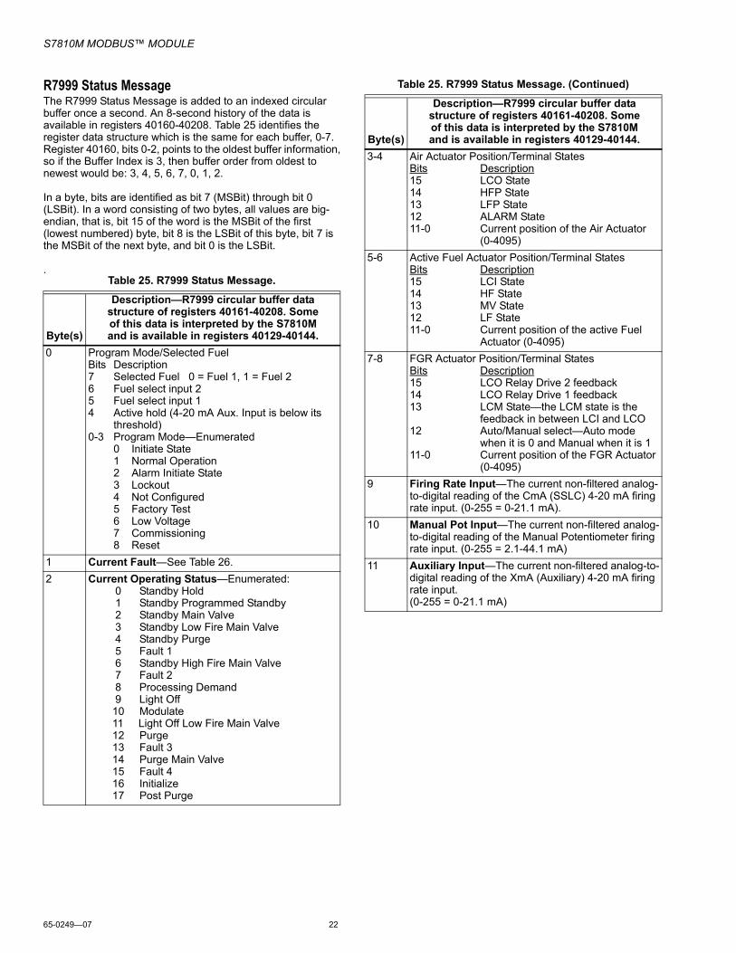
R7999 Status MessageThe R7999 Status Message is added to an indexed circular buffer once a second. An 8-second history of the data is available in registers 40160-40208. Table 25 identifies the register data structure which is the same for each buffer, 0-7. Register 40160, bits 0-2, points to the oldest buffer information, so if the Buffer Index is 3, then buffer order from oldest to newest would be: 3, 4, 5, 6, 7, 0, 1, 2.
In a byte, bits are identified as bit 7 (MSBit) through bit 0 (LSBit). In a word consisting of two bytes, all values are big-endian, that is, bit 15 of the word is the MSBit of the first (lowest numbered) byte, bit 8 is the LSBit of this byte, bit 7 is the MSBit of the next byte, and bit 0 is the LSBit.
.Table 25. R7999 Status Message.
Byte(s)
Description—R7999 circular buffer data structure of registers 40161-40208. Some of this data is interpreted by the S7810M and is available in registers 40129-40144.
0 Program Mode/Selected FuelBits Description7 Selected Fuel 0 = Fuel 1, 1 = Fuel 26 Fuel select input 25 Fuel select input 14 Active hold (4-20 mA Aux. Input is below its
threshold)0-3 Program Mode—Enumerated
0 Initiate State1 Normal Operation2 Alarm Initiate State3 Lockout4 Not Configured5 Factory Test6 Low Voltage7 Commissioning8 Reset
1 Current Fault—See Table 26.2 Current Operating Status—Enumerated:
0 Standby Hold 1 Standby Programmed Standby 2 Standby Main Valve 3 Standby Low Fire Main Valve 4 Standby Purge 5 Fault 1 6 Standby High Fire Main Valve 7 Fault 2 8 Processing Demand 9 Light Off 10 Modulate 11 Light Off Low Fire Main Valve 12 Purge 13 Fault 3 14 Purge Main Valve 15 Fault 4 16 Initialize 17 Post Purge
3-4 Air Actuator Position/Terminal StatesBits Description15 LCO State14 HFP State13 LFP State12 ALARM State11-0 Current position of the Air Actuator
(0-4095)5-6 Active Fuel Actuator Position/Terminal States
Bits Description15 LCI State14 HF State13 MV State12 LF State11-0 Current position of the active Fuel
Actuator (0-4095)7-8 FGR Actuator Position/Terminal States
Bits Description15 LCO Relay Drive 2 feedback14 LCO Relay Drive 1 feedback13 LCM State—the LCM state is the
feedback in between LCI and LCO12 Auto/Manual select—Auto mode
when it is 0 and Manual when it is 111-0 Current position of the FGR Actuator
(0-4095)9 Firing Rate Input—The current non-filtered analog-
to-digital reading of the CmA (SSLC) 4-20 mA firing rate input. (0-255 = 0-21.1 mA).
10 Manual Pot Input—The current non-filtered analog-to-digital reading of the Manual Potentiometer firing rate input. (0-255 = 2.1-44.1 mA)
11 Auxiliary Input—The current non-filtered analog-to-digital reading of the XmA (Auxiliary) 4-20 mA firing rate input. (0-255 = 0-21.1 mA)
Table 25. R7999 Status Message. (Continued)
Byte(s)
Description—R7999 circular buffer data structure of registers 40161-40208. Some of this data is interpreted by the S7810M and is available in registers 40129-40144.

S7810M MODBUS™ MODULE
23 65-0249—07
R7999 Fault TextThe R7999 Fault Text is shown indexed by hexadecimal values. A value of 0x11 means there is currently no fault.
Table 26. R7999 Fault Text.
Fault Code (hexadecimal) Fault Text
0x11 No Fault0x13 MV On0x14 HF and LF on0x15 Burner Control Transition0x25 Move Limit Test0x26 Target Move Test0x36 Fuel Selection0x37 HFP/LFP Output0x41 Air Pot Feedback0x42 F1 Pot Feedback0x43 F2 Pot Feedback0x44 FGR Pot Feedback0x45 Air Wiper Resistance0x46 F1 Wiper Resistance0x47 F2 Wiper Resistance0x48 FGR Wiper Resistance0x49 Air Total Resistance0x51 F1 Total Resistance0x52 F2 Total Resistance0x53 FGR Total Resistance0x58 Stuck Reset0x61 Initiate Timeout0x67 Fuel Off Curve0x68 FGR Off Curve0x69 Air Off Curve0x71 Air Offline0x72 F1 Offline0x73 F1 Offline0x74 FGR Offline0x82 Motor Speed0x83 Air No Response0x84 F1 No Response0x85 F2 No Response0x86 FGR No Response0x91 CmA Out of Range - Less than 3mA or greater than 20mA0x92 Manual Pot Range0x93 XmA Out of Range0x94 Demand Too Long0x99 Error Reading Fuel Selection

Automation and Control SolutionsHoneywell International Inc. Honeywell Limited-Honeywell Limitée1985 Douglas Drive North 35 Dynamic DriveGolden Valley, MN 55422 Toronto, Ontario M1V 4Z9customer.honeywell.com
S7810M MODBUS™ MODULE
® U.S. Registered Trademark© 2007 Honeywell International Inc.65-0249—07 M.S. Rev. 05-07