6.2.2007 beijing ilc workshop global design effort 1 high-gradient module test lutz lilje
TRANSCRIPT

6.2.2007 Beijing ILC Workshop Global Design Effort 1
High-Gradient Module Test
Lutz Lilje

6.2.2007 Beijing ILC Workshop Global Design Effort 2
Thanks!
• To D. Kostin, Rolf Lange, R. Paparella, K. Przygoda for the viewgraphs
• Many other people involved e.g. DESY technical groups etc.
• Dislaimer:– Some testing still on-going– Final evaluation after 10th cryo-cycle

6.2.2007 Beijing ILC Workshop Global Design Effort 3
Module Test at DESY
• A high gradient module has been assembled
• Test in dedicated test stand underway e.g.– Thermal cycles– Heat loads– Cavity
performance– Coupler
conditioning– Fast tuner
performance

6.2.2007 Beijing ILC Workshop Global Design Effort 4
Overall Module Performance
• Thermal cycling– 10 cycles total planned
• 7 done so far
– No leaks– Wire position o.k.
• Heat loads– Statical heat loads as other modules tested in
TTF/FLASH

6.2.2007 Beijing ILC Workshop Global Design Effort 5
Wire Positions
• Preliminary• Plot illustrates that
positions are repeatably achieved
• Final evaluation to follow
• Also on-going vibration measurements

6.2.2007 Beijing ILC Workshop Global Design Effort 6
Cavity Performance (courtesy D. Kostin – DESY)
1 - AC70 2 - AC76 3 - AC81 4 - Z87 5 - Z85 6 - Z92 7 - Z83 8 - Z900
5
10
15
20
25
30
35
40
Module 6
18.01.2007
EA
CC [M
V/m
]
Cavity
Cavity tests: Vertical (CW) Horizontal (10Hz) CMTB (2Hz) FLASH
Average gradient: 28 MV/m
planned

6.2.2007 Beijing ILC Workshop Global Design Effort 7
Q(Eacc)

6.2.2007 Beijing ILC Workshop Global Design Effort 8
HPP on Cavity 5 +6
• For short pulses up to 300 us gradient is high >30 MV/m
• Radiation levels are relatively low• This hints to a thermal quench
6.2.2007 Beijing ILC Workshop Global Design Effort 9
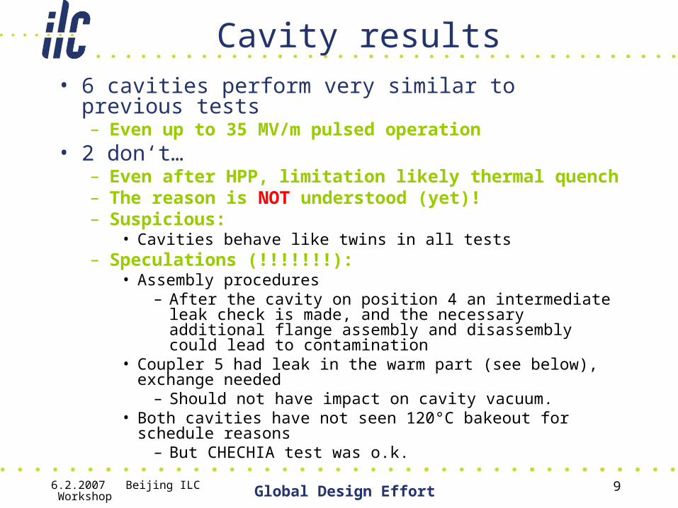
Cavity results• 6 cavities perform very similar to previous tests
– Even up to 35 MV/m pulsed operation• 2 don‘t…
– Even after HPP, limitation likely thermal quench– The reason is NOT understood (yet)!– Suspicious:
• Cavities behave like twins in all tests– Speculations (!!!!!!!):
• Assembly procedures– After the cavity on position 4 an intermediate leak check is
made, and the necessary additional flange assembly and disassembly could lead to contamination
• Coupler 5 had leak in the warm part (see below), exchange needed
– Should not have impact on cavity vacuum.• Both cavities have not seen 120°C bakeout for schedule
reasons– But CHECHIA test was o.k.
6.2.2007 Beijing ILC Workshop Global Design Effort 10
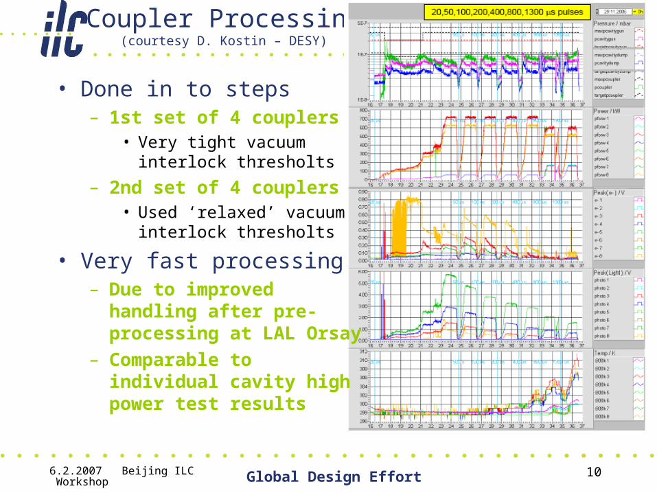
Coupler Processing(courtesy D. Kostin – DESY)
• Done in to steps– 1st set of 4 couplers
• Very tight vacuum interlock thresholts
– 2nd set of 4 couplers• Used ‘relaxed’ vacuum
interlock thresholts
• Very fast processing– Due to improved handling
after pre-processing at LAL Orsay
– Comparable to individual cavity high power test results

6.2.2007 Beijing ILC Workshop Global Design Effort 11

6.2.2007 Beijing ILC Workshop Global Design Effort 12

6.2.2007 Beijing ILC Workshop Global Design Effort 13
Coupler 5: Leak in Warm Part

6.2.2007 Beijing ILC Workshop Global Design Effort 14

6.2.2007 Beijing ILC Workshop Global Design Effort 15
Reconditioning after Repair

6.2.2007 Beijing ILC Workshop Global Design Effort 16
Second Set of Coupler

6.2.2007 Beijing ILC Workshop Global Design Effort 17

6.2.2007 Beijing ILC Workshop Global Design Effort 18
6.2.2007 Beijing ILC Workshop Global Design Effort 19
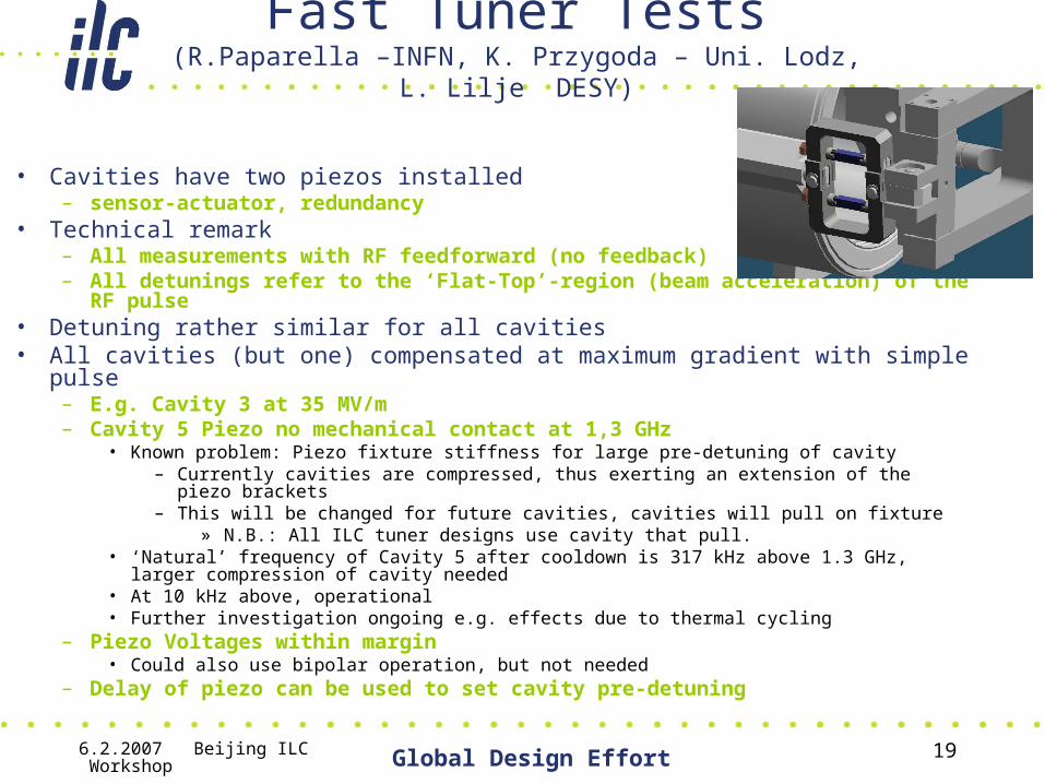
Fast Tuner Tests(R.Paparella –INFN, K. Przygoda – Uni. Lodz, L. Lilje DESY)
• Cavities have two piezos installed – sensor-actuator, redundancy
• Technical remark– All measurements with RF feedforward (no feedback)– All detunings refer to the ‘Flat-Top’-region (beam acceleration) of the RF pulse
• Detuning rather similar for all cavities• All cavities (but one) compensated at maximum gradient with simple pulse
– E.g. Cavity 3 at 35 MV/m– Cavity 5 Piezo no mechanical contact at 1,3 GHz
• Known problem: Piezo fixture stiffness for large pre-detuning of cavity– Currently cavities are compressed, thus exerting an extension of the piezo brackets– This will be changed for future cavities, cavities will pull on fixture
» N.B.: All ILC tuner designs use cavity that pull.• ‘Natural’ frequency of Cavity 5 after cooldown is 317 kHz above 1.3 GHz, larger
compression of cavity needed• At 10 kHz above, operational• Further investigation ongoing e.g. effects due to thermal cycling
– Piezo Voltages within margin• Could also use bipolar operation, but not needed
– Delay of piezo can be used to set cavity pre-detuning

6.2.2007 Beijing ILC Workshop Global Design Effort 20
Lorentz Force Detunings in Module 6 cavities
0
100
200
300
400
500
600
700
800
0 5 10 15 20 25 30 35 40
Eacc[MV/m]
Det
un
ing
ove
r F
lat-
To
p [
Hz]
C1C2C3C4C5C6C7C8

6.2.2007 Beijing ILC Workshop Global Design Effort 21
Example: Cavity 3Lorentz Force Detuning
0
100
200
300
400
500
600
700
800
0 5 10 15 20 25 30 35 40
Cavity Gradient [MV/m]
Lore
ntz
Forc
e de
tuni
ng [H
z]

6.2.2007 Beijing ILC Workshop Global Design Effort 22
Cavity 3: Gradient
35 MV/m

6.2.2007 Beijing ILC Workshop Global Design Effort 23
Cavity 3: Phase

6.2.2007 Beijing ILC Workshop Global Design Effort 24
Cavity 3: Detuning

6.2.2007 Beijing ILC Workshop Global Design Effort 25
Maximum Compensation per Cavity
Maximum Lorentz Force detuning compensation results
0
100
200
300
400
500
600
700
cav 1 - 35 MV/m cav 2 - 31 MV/m cav 3 - 35 MV/m cav 4 - 33 MV/m cav 6 - 20 MV/m cav 7 - 30 MV/m cav 8 - 23 MV/m
Det
unin
g ov
er th
e fla
t-top
[Hz]
Piezo OFF
Piezo ON

6.2.2007 Beijing ILC Workshop Global Design Effort 26
Voltage Needed for Compensation
Compensated Detuning vs. Applied Piezo Voltagehalf-sine pulse, 2.5 ms width and 0.6 to 0.64 ms advance from RF pulse
y = 7,594x
R2 = 0,98
0
100
200
300
400
500
600
700
0 10 20 30 40 50 60 70 80 90 100
Piezo Voltage [V]
Com
pens
ated
det
unin
g [H
z]
CAV 3
Linear (CAV 3)

6.2.2007 Beijing ILC Workshop Global Design Effort 27
Compensated Detuning vs. Delay to RF@25 MV/m
Normalized detuning over the flat-top for vs. piezo pulse delay
0,0
0,2
0,4
0,6
0,8
1,0
1,2
1,4
1,6
1,8
2,0
-7 -6 -5 -4 -3 -2 -1 0 1 2Piezo pulse start time [ms]
No
rma
lize
d a
mp
litu
de
Delay analysison cavity 1
Delay analysison cavity 2
Delay analysison cavity 6
Delay analysison cavity 7
2nd osc.compensationresults1st osc.compensationresults
RF pulse

6.2.2007 Beijing ILC Workshop Global Design Effort 28
Pre-Detuning Change Due to Piezo Pulse Delay
• Can change the cavity pre-detuning of the cavity by changing the delay of the ‘second‘ pulse in the order of 200Hz
• Changes in pre-detuning could be compensated by changing piezo delay instead of using stepper motor– Less motor usage,
increase lifetime
– Correponds to He drifts of a few mbar

6.2.2007 Beijing ILC Workshop Global Design Effort 29

6.2.2007 Beijing ILC Workshop Global Design Effort 30
Summary– No leaks, Static heat loads are o.k.– Cavities
• Six cavities show expected performance• Two cavites perform significantly below their individual high power
test results– Not understood (yet)
– Other components work well• Coupler processed quickly
– Improved handling paid off• Fast tuners perform up to 35 MV/m
– One exception: Problem of the fixture understood
– Module test stand is a big asset• Independent tests of FLASH• E.g. Rapid thermal Cycles

6.2.2007 Beijing ILC Workshop Global Design Effort 31
6.2.2007 Beijing ILC Workshop Global Design Effort 32