62 westbrook - handbook of mri technique, 3rd ed (free downloadbooksforradiographer)
TRANSCRIPT


Handbook of MRITechniqueThird Edition
Catherine WestbrookAnglia Ruskin UniversityCambridge, UK
A John Wiley & Sons, Ltd., Publication
9781405160858_1_pre.qxd 28/05/2008 15:14 Page iii

This edition first published 2008Second edition published 1999First edition published 1994© 1994, 1999, 2008 by Blackwell Publishing Ltd
Blackwell Publishing was acquired by John Wiley & Sons in February 2007. Blackwell’spublishing programme has been merged with Wiley’s global Scientific, Technical, andMedical business to form Wiley-Blackwell.
Registered officeJohn Wiley & Sons Ltd, The Atrium, Southern Gate, Chichester, West Sussex, PO19 8SQ,United Kingdom
Editorial office9600 Garsington Road, Oxford, OX4 2DQ, United Kingdom350 Main Street, Malden, MA 02148-5020, USA
For details of our global editorial offices, for customer services and for information abouthow to apply for permission to reuse the copyright material in this book please see ourwebsite at www.wiley.com/wiley-blackwell.
The right of the author to be identified as the author of this work has been asserted inaccordance with the Copyright, Designs and Patents Act 1988.
All rights reserved. No part of this publication may be reproduced, stored in a retrievalsystem, or transmitted, in any form or by any means, electronic, mechanical, photocopying,recording or otherwise, except as permitted by the UK Copyright, Designs and Patents Act1988, without the prior permission of the publisher.
Wiley also publishes its books in a variety of electronic formats. Some content that appearsin print may not be available in electronic books.
Designations used by companies to distinguish their products are often claimed astrademarks. All brand names and product names used in this book are trade names, servicemarks, trademarks or registered trademarks of their respective owners. The publisher is notassociated with any product or vendor mentioned in this book. This publication is designedto provide accurate and authoritative information in regard to the subject matter covered. It is sold on the understanding that the publisher is not engaged in rendering professionalservices. If professional advice or other expert assistance is required, the services of acompetent professional should be sought.
Library of Congress Cataloging-in-Publication DataWestbrook, Catherine.
Handbook of MRI technique / Catherine Westbrook. – 3rd ed.p. ; cm.
Includes index.ISBN-13: 978-1-4051-6085-8 (pbk. : alk. paper)ISBN-10: 1-4051-6085-3 (pbk. : alk. paper) 1. Magnetic resonance
imaging–Handbooks, manuals, etc. I. Title.[DNLM: 1. Magnetic Resonance Imaging–Handbooks. WN 39 W523h 2008]
RC78.7.N83W478 2008616.07′548–dc22
2007049687
A catalogue record for this book is available from the British Library.
Set in 10/12pt Sabon by Graphicraft Limited, Hong Kong
Printed in the USA by Sheridan Books, Inc., Chelsea, MI, USA
1 2008
9781405160858_1_pre.qxd 28/05/2008 15:14 Page iv


Contents
Contributors vii
Preface viii
Acknowledgements x
1 How to use this book 1
PART 1 Theoretical and practical concepts 13
2 Parameters and trade-offs 15
3 Pulse sequences 22
4 Flow phenomena and artefacts 34
5 Gating and respiratory compensation techniques 41
6 Patient care and safety 49
7 Contrast agents 55
PART 2 Examination areas 59
8 Head and neck 61Brain 63Temporal lobes 82Posterior fossa and internal auditory meati 89Pituitary fossa 96Orbits 101Paranasal sinuses 107Pharynx 111Larynx 117Thyroid and parathyroid glands 121Salivary glands 125Temporomandibular joints 129Vascular imaging 133
v
9781405160858_1_pre.qxd 28/05/2008 15:14 Page v

vi Contents
9 Spine 138Cervical spine 140Thoracic spine 150Lumbar spine 156Whole spine imaging 166
10 Chest 171Lungs and mediastinum 173Heart and great vessels 182Thymus 195Breast 198Axilla 210Brachial plexus 213
11 Abdomen 217Liver and biliary system 219Kidneys and adrenal glands 226Pancreas 233Vascular imaging 239
12 Pelvis 243Male pelvis 245Female pelvis 253Obstetrics 258
13 Upper limb 261Shoulder 263Humerus 273Elbow 277Forearm 285Wrist and hand 289
14 Lower limb 299Hips 301Femur 310Knee 314Tibia and fibula 325Ankle 329Foot 336Vascular imaging 343
15 Paediatric imaging 350
Index 398
9781405160858_1_pre.qxd 28/05/2008 15:14 Page vi

Contributors
Catherine Westbrook MSc, DCR(R), PgC (L&T), CT Cert, FHEASenior Lecturer and Post-Graduate Course Leader, Radiography, AngliaRuskin University, Cambridge, UK
John Talbot MSc, DCR(R), PgC (L&T) FHEASenior Lecturer, Radiography, Anglia Ruskin University, Cambridge, UK
William Faulkner BS RT(R), (MR) (CT), FSMRTWilliam Faulkner & Associates, LLC
Carolyn Kaut RT(R), (MR), (CT)(M)(CV),CEO, Imaging Education Associates
Michael Kean Dip. App. Sci., Grad. Dip. Edu.Senior Radiographer, Children’s MRI Centre, Royal Children’s Hospital,Melbourne, AustraliaResearch Affiliate – Murdoch Childrens Research Institute
vii
9781405160858_1_pre.qxd 28/05/2008 15:14 Page vii

Preface
The Handbook of MRI Technique is now an established text for manyMRI practitioners around the world. MRI in Practice (also published byBlackwell Publishing) provides radiographers and radiologists with auser-friendly approach to MRI theory and how it may be applied in prac-tice. The Handbook of MRI Technique is intended to guide the unini-tiated through scanning techniques and protocols and to help more experienced technologists improve image quality and recognize and rec-tify common artefacts. In many countries a lack of educational facilitiesand funding, as well as the complex nature of the subject, has resulted inpractitioners experiencing difficulty in learning MRI techniques. The sec-ond edition, published in 1999, has filled this gap and has proven to be auseful clinical text. In this, the third edition, it has been my intention tocontinue with the objectives of the second edition but update the readeron recent technical advances in both hardware and software. As previ-ously, technologists and radiographers from the UK, USA and Australiahave made large and important contributions to the book and, as a result,I believe the third edition is even more comprehensive than the second.
The Handbook of MRI Technique is split into two parts. Part 1 sum-marizes the main aspects of theory that relate to scanning and alsoincludes practical tips on gating and equipment use, patient care andsafety, and information on contrast media. Several useful tables are addedfor ease of reference and the pulse sequence section has been updated toinclude newer sequences. Part 2 includes a step-by-step guide to examin-ing each anatomical area. It covers most of the techniques commonly usedin MRI as well as paediatric imaging. Under each examination, categoriessuch as indications, patient positioning, equipment, artefacts and tips onoptimizing image quality are included. Guidance on technique and con-trast usage is also provided. Owing to the variety of imaging systems anddifferences in radiological preferences, information on protocols is mainlylimited to pulse sequence, scan plane and slice prescription. The advicegiven on protocols is only intended to direct the examination. In addition,a basic anatomy section has been added at the beginning of each examina-tion area.
The Handbook of MRI Technique provides a guide to the operation ofMR systems and to enhance the education of MR users. It is not intendedto be a clinical book as there are plenty of clinical specialist books on themarket. Therefore, apart from the Paediatric chapter in which several
viii
9781405160858_1_pre.qxd 28/05/2008 15:14 Page viii

Preface ix
clinical images are to be found, diagrams and images focus intentionallyon scan planes, slice prescriptions and sequencing to reflect the technicalthrust of the book.
The third edition of the Handbook of MRI Technique should be espe-cially beneficial to those technologists studying for board certification orpost-graduate and MSc courses, as well as to assistant practitioners,radiographers and radiologists who wish to further their knowledge ofMRI techniques. The contributing authors and I hope that it continues toachieve these goals.
Catherine Westbrook
9781405160858_1_pre.qxd 28/05/2008 15:14 Page ix

Acknowledgements
I must give my heart-felt thanks to the contributing authors: John Talbot,Bill Faulkner, Candi Kaut-Roth and Mike Kean without whom this bookcould never have been updated. As usual I am extremely impressed withtheir professional and thoughtful contributions and am very grateful fortheir valued opinions. In particular I would like to thank my friend andcolleague John Talbot for his beautiful illustrations and continued sup-port. Several have contributed towards the gallery of images. I would liketo thank the following; Kirk Odders, Chattanooga Imaging, LawrenceTanenbaum, MD and Philips Medical Systems.
CW
x
9781405160858_1_pre.qxd 28/05/2008 15:14 Page x


1
Introduction
This book has been written with the intention of providing a step-by-step explanation of the most common examinations currently carried out using Magnetic Resonance Imaging (MRI). It is divided into two parts.
Part 1 contains reviews or summaries of those theoretical and practicalconcepts that are frequently discussed in Part 2. These are:
• parameters and trade-offs• pulse sequences• flow phenomena and artefacts• gating and respiratory compensation techniques• patient care and safety• contrast agents.
These summaries are not intended to be comprehensive but containonly a brief description of definitions and uses. For a more detailed discus-sion of these and other concepts, the reader is referred to the several MRIphysics books now available. MRI in Practice by C. Westbrook, C. KautRoth and John Talbot (Blackwell Science, 2005, third edition) describesthem in more depth.
Part 2 is divided into the following examination areas:
• head and neck• spine• chest• abdomen• pelvis• upper limb• lower limb• paediatric imaging.
Each anatomical region is subdivided into separate examinations. For example, the section entitled Head and Neck includes explanations
1 How to use this book
1
9781405160858_4_001.qxd 28/05/2008 15:11 Page 1

2 Handbook of MRI Technique
on imaging the brain, temporal lobes, pituitary fossa, etc. Under eachexamination the following categories are described:
• basic anatomy• common indications• equipment• patient positioning• suggested protocol• image optimization.
Basic anatomy
Simple anatomical diagrams are provided for most examination areas toassist the reader.
Common indications
These are the most usual reasons for scanning each area, although occa-sionally some rarer indications are included.
Equipment
This contains a list of the equipment required for each examination and includes coil type, gating leads, bellows and immobilization devices.The correct use of gating and respiratory compensation is discussed in Part 1 (see Gating and respiratory compensation techniques). The coiltypes described are the most common currently available. These are asfollows.
• Volume coils that both transmit and receive radio-frequency (RF)pulses and are specifically called transceivers. Most of these coilsare quadrature coils, which means that they use two pairs of coils to transmit and receive signal, so improving the signal to noise ratio (SNR). They have the advantages of encompassing large areas of anatomy and yielding a uniform signal across the wholefield of view (FOV). The body coil is an example of this type of coil.
• Phased array coils consist of multiple coils and receivers. The signalfrom the receiver of each coil is combined to form one image. Thisimage has the advantages of both a small coil (improved SNR) andthose of the larger volume coils (increased coverage). Thereforephased array coils can be used either to examine large areas, such asthe entire length of the spinal cord, or to improve signal uniformityand intensity in small areas such as the breast. Phased array coilsare commonly used in spinal imaging.
1
9781405160858_4_001.qxd 28/05/2008 15:11 Page 2

How to use this book 3
• Surface/Local coils are traditionally used to improve the SNR whenimaging structures near to the skin surface. They are often speciallydesigned to fit a certain area and, in general, they only receive signal. RF is usually transmitted by the body coil when using thistype of coil. Surface coils increase SNR compared with volumecoils. This is because they are placed close to the region underexamination, thereby increasing the signal amplitude generated in the coil, and noise is only received in the vicinity of the coil.However, surface coils only receive signal up to the edges of the coiland to a depth equal to the radius of the coil. To visualize structuresdeep within the patient either a volume, phased array coil, parallelimaging coils or a local coil inserted into an orifice must be utilized(e.g. a rectal coil).
• Parallel imaging or multi-coils use the data from multiple coils orchannels arranged around the area under examination to eitherdecrease scan time and/or increase resolution. Additional softwareand hardware are required. The hardware includes several coilsperpendicular to each other or one coil with several channels. Thenumber of coils/channels varies but it is usually a minimum of 2and maximum of 32. During acquisition each coil fills its own linesof K space (e.g. if 2 coils are used together one coil fills the even linesof K space and the other the odd lines. K space is therefore filledeither twice as quickly or with twice the resolution in the same scantime). The number of coils/channels used is called the reduction factor and is similar in principle to the turbo factor/ETL in fast spinecho (see section on Pulse sequences in Part 1). Every coil producesa separate image which often displays aliasing artefact (see sectionon Artefacts in Part 1). Software removes aliasing and combines theimages from each coil to produce a single image. Most manufac-turers offer this technology, which can be used in any examinationarea and with any sequence. It has special advantages in brain andbody imaging.
The choice of coil for any examination is one of the most important factors that determine the resultant SNR of the image. When using anytype of coil remember to:
• Check that the cables are intact and undamaged.• Check that the coil is plugged in properly and that the correct con-
nector box is used.• Ensure that the receiving side of the coil faces the patient. This is
usually labelled on the coil itself. Note: Both sides of the coil receivesignal but coils are designed so that one side receives optimum signal. This is especially true of shaped coils that fit a certain anat-omical area. If the wrong side of the coil faces the patient, signal islost and image quality suffers.
• Place the coil as close as possible to the area under examination.The coil should not directly touch the patient’s skin as it maybecome warm during the examination and cause discomfort. A
1
9781405160858_4_001.qxd 28/05/2008 15:11 Page 3

4 Handbook of MRI Technique
small foam pad or tissue paper placed between the skin surface andthe coil is usually sufficient insulation.
• Ensure that the coil does not move when placed on the patient. Amoving coil during acquisition means a moving image!
• Always ensure that the receiving surface of the coil is parallel to the Z axis of the magnet. This guarantees that the transverse component of magnetization is perpendicular to the coil and that maximum signal is induced. Placing the coil at an angle to this axis, or parallel to the X or Y axis, results in a loss of signal(Figure 1.1).
Patient positioning
This contains a description of the correct patient position, placement ofthe patient within the coil and proper immobilization techniques. Cent-ring and land-marking are described relative to the laser light system as follows (Figure 1.2):
• The longitudinal alignment light refers to the light running parallelto the bore of the magnet in the Z axis.
• The horizontal alignment light refers to the light that runs from leftto right of the bore of the magnet in the X axis.
• The vertical alignment light refers to the light than runs from thetop to the bottom of the magnet in the Y axis.
It is assumed in Part 2 that the following areas are examined with thepatient placed head first in the magnet:
• head and neck (all areas)• cervical, thoracic and whole spine• chest (all areas)• abdomen (for areas superior to the iliac crests)• shoulders and upper limb (except where specified).
The remaining anatomical regions are examined with the patient placedfeet first in the magnet. These are:
• pelvis• hips• lower limbs.
Suggested protocol
This is intended as a guideline only. Almost every centre uses differentprotocols depending on the type of system and radiological preference.However, this section can be helpful for those practitioners scanningwithout a radiologist, or where the examination is so rare that perhapsneither the radiologist nor the practitioner knows how to proceed. The
1
9781405160858_4_001.qxd 28/05/2008 15:11 Page 4

1
Figure 1.1 Correct placementof a flat surface coil in the boreof the magnet. The surface ofthe coil (shaded) area must beparallel to the Z axis to receivesignal. The coil is thereforepositioned so that transversemagnetization created in the Xand Y axes is perpendicular tothe coil.
9781405160858_4_001.qxd 28/05/2008 15:11 Page 5

6 Handbook of MRI Technique
protocols given are mainly limited to scan plane, weighting, suggestedpulse sequence choices and slice positioning.
It must be stressed that all the protocols listed are only a reflection ofthe authors’ practice and research, and are in no way to be considered thelaw!
If all your established protocols are satisfactory, this section is includedfor interest only. If, however, you are unfamiliar with a certain examina-tion, the suggested protocol should be useful.
Occasionally in this section coordinates for slice prescription are given in bold type in millimetres (mm) where explicit prescription can beutilized (mainly for localizers). Graphic prescription coordinates cannotbe given as they depend on the exact position of the patient within themagnet and the ROI. The explicit coordinates are always given as follows:
• Left to Right L to R• Inferior to Superior I to S• Posterior to Anterior P to A.
In the suggested protocols a certain format is adopted when someparameters remain constant and others change. For example, in the pro-tocol for a coronal spin echo (SE), proton density (PD)/T2 sequence of thebrain the text reads.
Coronal SE/FSE PD/T2
As for Axial PD/T2, except prescribe slices from the cerebellum to thefrontal lobe.
This indicates that the pulse sequence, timing parameters, slice thick-ness and matrix are the same as the axial except the slices are prescribedthrough a different area. This format is intended to avoid repetition. Inmost examinations there is a section reserved for additional sequences.These are extra sequences that we do not regard as routine but may be
1
Figure 1.2 Positioning of thealignment lights.
9781405160858_4_001.qxd 28/05/2008 15:11 Page 6

How to use this book 7
included in the examination. Of course, some practitioners may regardwhat we call ‘additional’ as ‘routine’, and vice versa.
Image optimization
This section is subdivided into:
• Technical issues• Artefact problems• Patient considerations• Contrast usage.
• Technical issues: This includes a discussion of the relationship ofSNR, spatial resolution and scan time pertaining to each examina-tion. Suggestions on how to optimize these factors are described(see Parameters and trade-offs in Part 1). The correct use of pulsesequences and various imaging options are also discussed (see alsoPulse sequences in Part 1).
• Artefact problems: This contains a description of the common artefacts encountered and ways in which they can be eliminated orreduced (see also Flow phenomena and artefacts in Part 1).
• Patient considerations: This encompasses the condition of thepatient, including symptoms and claustrophobia. Suggestions toovercome these are given (see also Patient care and safety in Part 1).
• Contrast usage: The reasons for administering contrast in each particular area are discussed. Again, contrast usage varies widelyaccording to radiological preferences. This section is a guidelineonly (see also Contrast agents in Part 1).
Follow this ten point plan for good radiographic practice:
• Review all cases carefully and select appropriate protocols.• Have flexible protocols that can reflect the needs of each individual
clinical case.• Regularly review your procedures and benchmark them against
current best practice.• Have clear diagnostic goals including the minimum accepted
sequences necessary to obtain a useful diagnostic/clinical outcome.• Regularly review your protocols and procedures.• Understand the capabilities of your system.• Recognize your limitations and if necessary refer to another site
rather than risking an incomplete or diagnostically unacceptableprocedure.
• Educate all levels of staff to new procedures and/or system capabilities.
• Be safety paranoid to ensure your unit does not fall victim to thedreaded MRI incident.
• Most importantly, enjoy your patients and give them the higheststandard of care possible.
1
9781405160858_4_001.qxd 28/05/2008 15:11 Page 7

8 Handbook of MRI Technique
Terms and abbreviations used in Part 2
Wherever possible generic terms have been used to describe pulse sequencesand imaging options. Explanations of these can be found in the varioussections of Part 1. To avoid ambiguity the specific following terms havebeen used:
• Chemical/Spectral presaturation: fat suppression techniques suchas fat saturation (FAT SAT), spectrally selective inversion recovery(SPIR).
• Gradient moment nulling (GMN): gradient moment rephasing(GMR) and flow compensation (FC).
• Oversampling: no phase wrap, anti-aliasing and anti-foldover.• Rectangular/Asymmetric FOV: rectangular FOV.• Respiratory compensation (RC): phase reordering and respiratory
triggering techniques.
Abbreviations are used throughout the book for simplification purposes.A summary of these can be found in the following section Abbreviations.In addition a comparison of acronyms used by certain manufacturers todescribe pulse sequences and imaging options is given later in Table 3.1under Pulse sequences in Part 1.
Conclusion
To use this book:
• Find the anatomical region required and then locate the specificexamination.
• Study the categories under each section. It is possible that all thecategories are relevant if the examination is being performed for thefirst time. However, there may be occasions when only one item isappropriate. For example, there could be a specific artefact that isregularly observed in chest examinations, or image quality is not upto standard on lumbar spines. Under these circumstances read thesubsection above entitled Image optimization.
• If the terms used, or concepts discussed, in Part 2 are unfamiliar,then turn to Part 1 and read the summaries described there.
1
9781405160858_4_001.qxd 28/05/2008 15:11 Page 8

How to use this book 9
Abbreviations
A summary of common abbreviations used in the field of MRI andthroughout this book is given below.
A AnteriorAC Number of acquisitionsADC Apparent diffusion coefficientADEM Acute disseminating encephalomyelitisASIS Anterior superior iliac spineAVM Arterio-venous malformationAVN Avascular necrosisBFFE Balanced fast field echoBGRE Balanced gradient echoBOLD Blood oxygenation level dependentCDH Congenitally dislocated hipsCE-MRA Contrast enhanced MRACNR Contrast to noise ratioCNS Central nervous systemCSE Conventional spin echoCSF Cerebrospinal fluidCT Computer tomographyCVA Cerebral vascular accidentDE prep Driven equilibrium magnetization preparationDTI Diffusion tensor imagingDWI Diffusion weighted imagingECG EchocardiogramEPI Echo planar imagingETL Echo train lengthFA Fractional anisotropyFAT SAT Fat saturationFC Flow compensationFDA Food and Drugs AdministrationFFE Fast field echoFIESTA Free induction echo stimulated acquisitionFID Free induction decay signalFISP Fast imaging with steady precessionFLAIR Fluid attenuated inversion recoveryFLASH Fast low angled shotfMRI Functional MRIFOV Field of viewFSE Fast spin echoGFE Gradient field echoGMN Gradient moment nullingGMR Gradient moment rephasingGRASS Gradient recalled acquisition in the steady stateGRE Gradient echo
1
9781405160858_4_001.qxd 28/05/2008 15:11 Page 9

10 Handbook of MRI Technique
GRE-EPI Gradient echo EPIHASTE Half acquisition single shot turbo SEI InferiorIAM Internal auditory meatus(i)IM IntramuscularIR Inversion recoveryIR-FSE Inversion recovery FSEIR prep Inversion recovery magnetization preparationIV IntravenousIVC Inferior vena cavaL LeftMP RAGE Magnetization prepared rapid gradient echoMR Magnetic resonanceMRA Magnetic resonance angiographyMRCP Magnetic resonance cholangiopancreatographyMRI Magnetic resonance imagingMS Multiple sclerosisMT Magnetization transferNEX Number of excitationsNSA Number of signal averagesP PosteriorPC Phase contrastPC-MRA Phase contrast MRAPD Proton densityPe PeripheralPEAR Phase encoding artefact reductionPSIF Reverse FISPR RightRC Respiratory compensationREST Regional saturation techniqueRF Radio frequencyROI Region of interestRR R to R intervalS SuperiorSAR Specific absorption rateSAT SaturationSE Spin echoSE-EPI Spin echo EPISNR Signal to noise ratioSPAMM Spatial modulation of magnetizationSPGR Spoiled GRASSSPIR Spectrally selective inversion recoverySS Single shotSS-EPI Single shot EPISSFP Steady state free precessionSS-FSE Single shot FSESTIR Short TAU inversion recoverySW Susceptibility weighted
1
9781405160858_4_001.qxd 28/05/2008 15:11 Page 10

How to use this book 11
TE Echo timeTFE Turbo field echoTI Inversion timeTIA Transient ischaemic attackTLE Temporal lobe epilepsyTMJ Temporomandibular jointTOF Time of flightTOF-MRA Time of flight MRATR Repetition timeTrue FISP Siemens version of BGETSE Turbo spin echoVENC Velocity encoding
1
9781405160858_4_001.qxd 28/05/2008 15:11 Page 11

9781405160858_4_001.qxd 28/05/2008 15:11 Page 12

Part 1 Theoretical and practicalconcepts
9781405160858_4_002.qxd 28/05/2008 15:16 Page 13

9781405160858_4_002.qxd 28/05/2008 15:16 Page 14

2
Introduction
This section refers mainly to the Technical issues subheading discussedunder the Image optimization heading considered for each examinationin Part 2. Only a brief overview is provided here. For a more detailedexplanation please refer to Chapter 4 of MRI in Practice or an equivalenttext.
The main considerations of image quality are:
• signal to noise ratio (SNR)• contrast to noise ratio (CNR)• spatial resolution• scan time.
Each factor is controlled by certain parameters, and each ‘trades off ’against the other (see later in Table 2.2). This section summarizes theparameters available and the trade-offs involved. Suggested parametersare outlined in Table 2.1, which can be found here and at the beginning of each anatomical region in Part 2. The parameters given should be universally acceptable on most systems. However, weighting parametersin particular are field-strength dependent and therefore some modifica-tion may be required if you are operating at extremely low or high fieldstrengths.
Signal to noise ratio (SNR)
The signal to noise ratio (SNR) is defined as the ratio of the amplitude ofsignal received by the coil to the amplitude of the noise. The signal is thevoltage induced in the receiver coil, and the noise is a constant valuedepending on the area under examination and the background electricalnoise of the system. SNR may be increased by using:
• spin echo (SE) and fast spin echo (FSE) pulse sequences• a long repetition time (TR) and a short echo time (TE)• a flip angle of 90°• a well-tuned and correctly sized coil• a coarse matrix
2 Parameters and trade-offs
15
9781405160858_4_002.qxd 28/05/2008 15:16 Page 15

16 Handbook of MRI Technique
2
Table 2.1 Summary of parameters. The figures given are general and should beadjusted according to the system used
Spin echo (SE)short TE min to 30 mslong TE 70 ms +short TR 300–600 mslong TR 2000 ms +
Fast spin echo (FSE)short TE min–20 mslong TE 90 ms +short TR 400–600 mslong TR 4000 ms +short ETL 2–6long ETL 16 +
Inversion recovery (IR) T1short TE min–20 mslong TR 3000 ms +medium TI 200–600 msshort ETL 2–6
STIRlong TE 60 ms +long TR 3000 ms +short TI 100–175 mslong ETL 12–20
FLAIRlong TE 60 ms +long TR 3000 ms +long TI 1700–2200 mslong ETL 12–20
Slice thickness2D thin 2–4 mm
medium 5–6 mmthick 8 mm
3D thin ≤ 1 mmthick ≥ 3 mm
FOVsmall ≤ 18 cmmedium 18–30 cmlarge ≥ 30 cm
NEX/NSAshort ≤ 1medium 2–3multiple ≥ 4
Coherent GRElong TE 15 ms +short TR ≤ 50 msflip angle 20°–40°
Incoherent GREshort TE min–5 msshort TR ≤ 50 msflip angle 20°–40°
Balanced GRETE minimumTR minimumflip angle ≥ 40°
SSFPTE minimumTR 40–50 msflip angle 20°–40°
Slice numbersVolumes small ≤ 32
medium 64large ≥ 128
Matrix (frequency ×× phase)coarse 256 × 128 or 256 × 192medium 256 × 256 or 512 × 256fine 512 × 512very fine ≥ 512 × 512
PC-MRA2D and 3D TE minimum
TR 25–33 msflip angle 30°
VENC venous 20–40 cm/sVENC arterial 60 cm/s
TOF-MRA2D TE minimum
TR 28–45 msflip angle 40°–60°
3D TE minimumTR 25–50 msflip angle 20°–30°
9781405160858_4_002.qxd 28/05/2008 15:16 Page 16

Parameters and trade-offs 17
• a large FOV• thick slices• the narrowest receive bandwidth available• as many excitations and signal averages (NEX/NSA) as possible.
In Part 2, the following terms and approximate parameters are sug-gested when discussing the number of signal averages (NEX/NSA) (seealso Table 2.1):
• short NEX/NSA is 1 or less (partial averaging)• medium NEX/NSA is 2/3• long or multiple NEX/NSA is 4 or more.
Contrast to noise ratio (CNR)
The contrast to noise ratio (CNR) is defined as the difference in the SNRbetween two adjacent areas. It is controlled by the same factors that affectthe SNR. All examinations should include images that demonstrate agood CNR between pathology and surrounding normal anatomy. In thisway pathology is well visualized. The CNR between pathology and otherstructures can be increased by the following:
• Administration of contrast agents.• Utilization of T2 weighted sequences.• Selection of magnetization transfer (MT) sequences.• Suppression of normal tissues via chemical/spectral presaturation,
or sequences that null signal from certain tissues: short TI inver-sion recovery (STIR), fluid alternated inversion recovery (FLAIR),magnetization-prepared sequences).
Spatial resolution
The spatial resolution is the ability to distinguish between two points asseparate and distinct. It is controlled by the voxel size. Spatial resolutionmay be increased by selecting:
• thin slices• fine matrices• a small FOV.
The above criteria assume a square FOV so that if an uneven matrix is used, the pixels are rectangular and therefore resolution is lost. Somesystems utilize square pixels so that the phase matrix determines the sizeof the FOV along the phase encoding axis. In this way resolution is maintained because the pixels are always square. The disadvantage of thissystem is that the size of the FOV may be inadequate to cover the requiredanatomy in the phase direction, and SNR is often reduced due to the use
2
9781405160858_4_002.qxd 28/05/2008 15:16 Page 17

18 Handbook of MRI Technique
of smaller, square pixels. Therefore these systems usually have the optionto utilize a square FOV in circumstances where either coverage is requiredor the SNR is low. In the interests of simplicity, a square FOV is assumedin Part 2, whereby the phase matrix size determines the resolution of theimage, not the size of the FOV.
In Part 2 the following terms and approximate parameters are sug-gested when discussing spatial resolution. The first number quoted is thefrequency matrix, the second is the phase matrix (see also Table 2.1):
• a coarse matrix is 256 × 128 or 256 × 192• a medium matrix is 256 × 256 or 512 × 256• a fine matrix is 512 × 512• a very fine matrix is any matrix greater than 512 × 512• a small FOV is usually less than 18 cm• a large FOV is more than 30 cm• on the whole, the FOV should fit the ROI• a thin slice/gap is 1 mm/1 mm to 4 mm/1.5 mm or less• a medium slice/gap is 5 mm/2.5 mm to 6 mm/2.5 mm• a large slice/gap is 8 mm/2 mm or more.
Scan time
The scan time is the time required to complete the acquisition of data. Thescan time can be decreased by using:
• a short TR• a coarse matrix• the lowest NEX/NSA possible.
In addition to the SNR, CNR, spatial resolution and scan time, the following imaging options are also described under the Technical issuessubheading mentioned before.
• Rectangular/asymmetric FOV: The use of rectangular/asymmetricFOV is often discussed in Part 2. It enables the acquisition of finematrices but in scan times associated with coarse matrices. It ismost useful when anatomy fits into the shape of a rectangle, e.g.sagittal spine. The long axis of the rectangle usually corresponds tothe frequency encoding axis and the shorter axis to phase encoding.This is important as certain phase artefacts, such as ghosting andaliasing, occur along the short axis of the rectangle. The dimensionof the phase axis is usually expressed as a proportion or percentageof the frequency axis, e.g. 75%. On some systems, rectangular/asymmetric FOV and oversampling are not compatible. If this is so, signal-producing anatomy existing beyond the FOV along theshorter phase axis is wrapped into the image. This is reduced byincreasing the FOV, using spatial presaturation bands to nullifyunwanted signal or, if this function is available, by expanding the
2
9781405160858_4_002.qxd 28/05/2008 15:16 Page 18

Parameters and trade-offs 19
short axis dimension to incorporate all signal-producing anatomy(see Flow phenomena and artefacts).
• Volume imaging: Volume imaging or 3D acquisition collects datafrom an imaging volume or slab and then applies an extra phaseencoding along the slice select axis. In this way, very thin slices withno gap are obtained, and the data set may be viewed in any plane.However the scan time in volume imaging not only depends on theTR, the phase matrix and the number of signal averages/but also onthe number of slice locations in the volume. Therefore scan timesare considerably longer than in 2D imaging. For this reason fastsequences such as steady state sequences and FSE are commonlyused (see Pulse sequences). To maintain resolution in all viewingplanes, the voxels should be isotropic, i.e. they have the samedimensions in all three planes. This is achieved by selecting an evenmatrix and a slice thickness equal to, or less than, the pixel size. Forexample, if a matrix size of 256 × 256 is chosen and the FOV is 25cm, a slice thickness of 1 mm achieves the required resolution. Witha larger FOV a slightly thicker slice can be used. The penalty ofisotropic voxels, however, is a reduction in SNR due to the use ofsmaller, square voxels. In addition more slices may be required tocover the imaging volume resulting in long scan times. This is com-pensated for to some degree by the fact that, as there are no gaps, agreater volume of tissue is excited and therefore overall signalreturn is greater. Nevertheless when volume imaging is employed,the need for resolution in all planes must be weighed against someloss of SNR and longer scan times. As the slices are not individuallyexcited as in conventional acquisitions, but are located by an extraphase encoding gradient, aliasing along the slice select axis occurs.This originates from anatomy that lies within the coil (and there-fore produces signal), and exists outside the volume along the slice encoding axis. It manifests itself by the first and last few slicesof the imaging volume wrapping into each other and potentiallyobscuring important anatomy. To avoid this always over-prescribethe volume slab so that the ROI, and some anatomy on either sideof it, are included. In this way any slice wrap does not interfere with the ROI (see Flow phenomena and artefacts). Volume imagingis commonly used in the brain and to examine joint anatomy, espe-cially when very thin slices are required. In Part 2 the followingterms and approximate parameters are suggested when discussingvolume imaging (see also Table 2.1):
• A thin slice is 1 mm or less.• A thick slice is more than 3 mm.• A small number of slice locations is approximately 32.• A medium number of slice locations is approximately 64.• A large number of slice locations is approximately 128 or more.
The following combination of parameters usually yields the optimumSNR and scan time in volume imaging, although this depends on the coil
2
9781405160858_4_002.qxd 28/05/2008 15:16 Page 19

20 Handbook of MRI Technique
type, the proton density of the area under examination, the slice thick-ness, and the field strength:
• 32 locations use 2 or more NEX/NSA• 64 locations use 1 NEX/NSA• 128 locations use less than 1 NEX/NSA.
Decision strategies
To optimize image quality the data should have a high SNR, good resolu-tion and be acquired in a short scan time. This is usually impossible. however, as the factors that must be increased to improve SNR may haveto be decreased to gain spatial resolution. An example of this is matrixselection. A coarse matrix is required to obtain large voxels and thereforea high SNR. However, a fine matrix with small voxels and low SNR is not only necessary to maintain good spatial resolution, but also increasesthe scan time as more phase encodings are performed. The operator must decide which factor (either SNR, resolution or scan time) is the mostimportant and optimize this. One or both of the other two may have to besacrificed accordingly.
When discussing these issues in Part 2 the importance of good SNRover the other factors is emphasized, as in our view there is little point in having an image with good resolution if the SNR is poor. The selectionof an appropriately sized and tuned coil is also important, together with the proton density of the area under examination. For example,when examining the chest, which has a low SNR, the parameters selectedmust optimize the SNR as much as possible, and resolution and scan time are sacrificed. The importance of limiting the scan time for patienttoleration is also discussed in Part 2. If the scan time is lengthy, all patientswill eventually become uncomfortable and move. The resultant motionartefact degrades any image regardless of its SNR or resolution character-istics. Therefore it is important to minimize scan times to acceptable levels. If patients are in pain or uncooperative, this strategy is even moreimportant.
Conclusion
The variety of parameters used in MRI is often bewildering, but theirimportance is undisputed, especially in determining image quality. Agood working knowledge of these parameters and how they interrelate isnecessary to ensure an optimum examination. Table 2.2 summarizesthese trade-offs. The choice of pulse sequence is also important in deter-mining image contrast, and these are outlined in the next section.
2
9781405160858_4_002.qxd 28/05/2008 15:16 Page 20

Parameters and trade-offs 21
2
Table 2.2 Parameters and their trade-offs
Parameter
TR increased
TR decreased
TE increasedTE decreasedNEX increased
NEX decreased
Slice thickness increased
Slice thickness decreased
FOV increased
FOV decreased
Matrix increased
Matrix decreased
Receive bandwidth increasedReceive bandwidth decreased
Advantages
Increased SNRIncreased number of slicesper acquisitionDecreased scan timeIncreased T1 weighting
Increased T2 weightingIncreased SNRIncreased SNR of all tissuesReduced flow artefact due tosignal averagingDirect proportional decreasein scan time
Increased SNR in all tissuesIncreased coverage ofanatomyIncreased spatial resolutionand reduced partialvoluming in slice selectdirectionIncreased SNRIncreased coverage ofanatomyDecreased SNR in alltissuesDecreased coverage ofanatomyIncreased spatial resolution
Increased SNR in all tissuesif pixel size increases. If pixelsize remains the same, SNRdecreases as fewer phaseencodings are performed.Decreased scan timeDecrease of minimum TEDecrease in chemical shiftIncreased SNR
Disadvantages
Increased scan timeDecreased T1 weighting
Decreased SNRDecreased number of slicesper acquisitionDecreased SNRDecreased T2 weightingDirect proportional increasein scan time
Decreased SNR in all tissuesIncreased flow artefact due toless signal averagingDecreased spatial resolutionand partial voluming in sliceselect directionDecreased SNR in all tissuesDecreased coverage ofanatomy
Decreased spatial resolutionDecreased likelihood ofaliasingIncreased spatial resolutionIncreased likelihood ofaliasing
Decreased SNR if pixel sizedecreases. If pixel sizeremains the same, SNR willincrease because morephase encodings areperformed.Increased scan timeDecreased spatial resolution
Decreased SNR
Increase in minimum TEIncrease in chemical shift
9781405160858_4_002.qxd 28/05/2008 15:16 Page 21

3
Introduction
This section refers mainly to the Suggested protocol heading consideredfor each examination in Part 2, although pulse sequences are sometimesmentioned under the Technical issues subheading of Image optimization.A summary of the mechanisms and uses of the most commonly used pulsesequences are described. All pulse sequences are described using theirgeneric name. Table 3.1 provides a comparison of the acronyms used bythe main manufacturers to describe their pulse sequences and imagingoptions. The parameters given in Table 2.1 should be universally accept-able on most systems. However, weighting parameters in particular are field-strength dependent and therefore some modification may berequired if you are operating at extremely low or high field strengths.Only a brief overview is provided here. For a more detailed explanationplease refer to Chapters 2 and 5 of MRI in Practice or an equivalent text.
Spin echo (SE)
A spin echo (SE) pulse sequence (also known as conventional spin echo(CSE) ) usually uses a 90° excitation pulse followed by a 180° rephasingpulse to produce a spin echo. Some SE sequences use a variable flip angle, but traditionally the excitation pulse has a magnitude of 90°. Thisamplitude of the flip angle is consistently assumed in the protocols. SE sequences can be used to generate one or several spin echoes. One echois usually used for T1 weighting while two echoes are used for proton density (PD) and T2 weighting. SE pulse sequences are the most com-monly implemented sequences as they produce optimum SNR and CNR.
For T1 weighting in SE use: For PD/T2 weighting in SE use:
short TE min–20 ms short TE 20 ms (first echo PD)short TR 300–600 ms long TE 70 ms (second echo T2)
long TR 2000 ms
3 Pulse sequences
22
9781405160858_4_003.qxd 28/05/2008 15:17 Page 22

Pulse sequences 23
Fast spin echo (FSE) or turbo spin echo (TSE)
Fast spin echo (FSE) uses a 90° flip angle followed by several 180° rephas-ing pulses to produce several spin echoes in a given TR. Each echo is phaseencoded with a different amplitude of gradient slope, so that data fromeach echo are collected and stored in a different line of K space. In thisway more than one line of K space is filled per TR, and the scan time isreduced accordingly. The echo train length (ETL) (also known as theturbo factor) refers to the number of 180° rephasing pulses and thereforeechoes that correspond to the number of lines of K space filled per TR.The longer the ETL the shorter the scan time as more lines of K space arefilled per TR.
FSE can be used to produce either one or two echoes as in SE. The echotrain may be split so that data are collected from the first half of the echotrain to acquire the first echo, and from the latter half to acquire the sec-ond echo. This strategy is commonly used to produce PD and T2 imagesthat demonstrate similar weighting to SE. However, T2 images can beacquired without a PD image. A T2 image alone, rather than a dual echo,is often acquired in Part 2. It is of course perfectly justified to use a dualecho sequence if this is required. For more information see TechnicalIssues in Brain in Part 2.
FSE sequences have been further modified to include 3D acquisitionsand single-shot techniques. Single shot FSE (SS-FSE), which is also termed
3
Table 3.1 Comparison of manufacturer acronyms (see How to use this book forabbreviations)
Pulse sequence/Imaging General Philips Siemensoption Electric
Spin echo Spin echo Spin echo Spin echoFast spin echo FSE TSE TSECoherent gradient echo GRASS FFE FISPBalanced gradient echo FIESTA BFFE True FISPIncoherent gradient echo SPGR T1 FFE FLASHSteady state free precession SSFP T2 FFE PSIFInversion recovery (IR) IR IR IRShort TI inversion recovery STIR STIR STIRFluid attenuated inversion FLAIR FLAIR FLAIRrecoveryPresaturation SAT REST SATGradient moment nulling FC FC GMRRespiratory compensation RC PEAR RCSignal averaging NEX NSA ACPartial averaging Fractional NEX Half scan Half FourierOversampling No phase wrap Fold over Oversampling
suppressionRectangular/asymmetric Rectangular Rectangular UndersamplingFOV FOV FOV FOV
9781405160858_4_003.qxd 28/05/2008 15:17 Page 23

24 Handbook of MRI Technique
HASTE (half acquisition single shot turbo echo), combines long ETLswhich fill all of K space in one shot with half Fourier acquisition tech-niques that acquire only half of K space and then transpose data into theother half. This technique allows very rapid acquisitions, which enablesmultiple slice breath-hold and real-time imaging.
Some contrast characteristics of FSE differ from conventional SE. Fatremains bright on T2 weighted images and fat suppression techniquesmay be needed to compensate for this. The multiple 180° RF pulses usedin FSE sequences cause lengthening of the T2 decay time of fat so that thesignal intensity of fat on T2 weighted FSE images is higher than in SE.This sometimes makes the detection of marrow abnormalities difficult.Therefore when imaging the vertebral bodies for metastatic disease, aSTIR sequence should be utilized. Muscle can appear darker than usualespecially on the T2 weighted images. This is again due to the multiple180° pulses causing a MT effect.
In addition, certain artefacts may be prominent in FSE sequences.Image blurring is often a problem in long ETL sequences. This occursbecause each line of K space contains data from echoes with a differentTE. In long ETL sequences, the very late echoes have a low signal ampli-tude and, as the outer lines of K space are filled with data from theseechoes, there are insufficient data to provide adequate resolution. Imageblurring is most commonly seen at the edges of tissues with different T2decay times. It may be reduced by decreasing the size of the FOV in thephase direction (depending on how the manufacturer implements a rapidFSE sequence) or by selecting a broad receive bandwidth. However, whilethe latter does improve overall image quality by reducing blurring, it also reduces the SNR. Lastly, FSE is not always compatible with optionssuch as phase reordered respiratory compensation (RC) and thereforeconventional SE or breath-hold sequences are often the sequence of choicewhen respiratory artefact is likely to be troublesome.
For T1 weighting in FSE use: For T2 weighting in FSE use:
short TE min–20 ms long TE ≥ 90 msshort TR 400–600 ms long TR ≥ 4000 msshort ETL 2–6 long ETL ≥ 16
For PD/T2 weighting in FSE use:
short TE min–20 ms (first echo PD)long TE ≥ 90 ms (second echo T2)long TR ≥ 4000 msmedium ETL 8–12 (split 4 and 4 or 6 and 6)
Inversion recovery (IR/IR-FSE)
Inversion recovery (IR) pulse sequences begin with a 180° pulse thatinverts the net magnetization vector into full saturation. When the invert-ing pulse is removed, the magnetization begins to recover and return
3
9781405160858_4_003.qxd 28/05/2008 15:17 Page 24
Pulse sequences 25
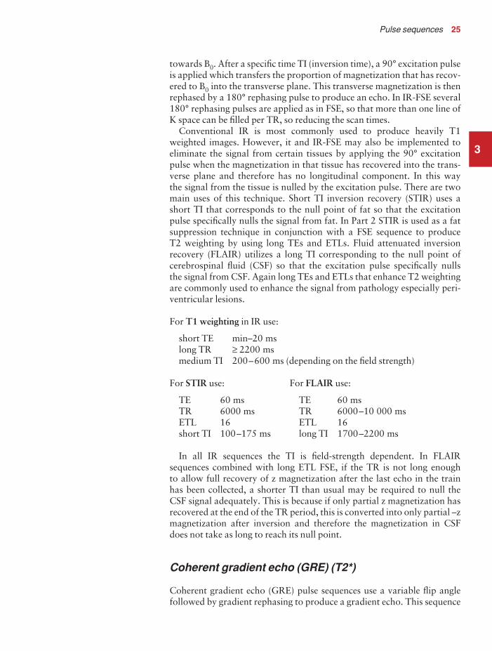
towards B0. After a specific time TI (inversion time), a 90° excitation pulseis applied which transfers the proportion of magnetization that has recov-ered to B0 into the transverse plane. This transverse magnetization is thenrephased by a 180° rephasing pulse to produce an echo. In IR-FSE several180° rephasing pulses are applied as in FSE, so that more than one line ofK space can be filled per TR, so reducing the scan times.
Conventional IR is most commonly used to produce heavily T1weighted images. However, it and IR-FSE may also be implemented toeliminate the signal from certain tissues by applying the 90° excitationpulse when the magnetization in that tissue has recovered into the trans-verse plane and therefore has no longitudinal component. In this way the signal from the tissue is nulled by the excitation pulse. There are twomain uses of this technique. Short TI inversion recovery (STIR) uses ashort TI that corresponds to the null point of fat so that the excitationpulse specifically nulls the signal from fat. In Part 2 STIR is used as a fatsuppression technique in conjunction with a FSE sequence to produce T2 weighting by using long TEs and ETLs. Fluid attenuated inversionrecovery (FLAIR) utilizes a long TI corresponding to the null point ofcerebrospinal fluid (CSF) so that the excitation pulse specifically nulls the signal from CSF. Again long TEs and ETLs that enhance T2 weightingare commonly used to enhance the signal from pathology especially peri-ventricular lesions.
For T1 weighting in IR use:
short TE min–20 mslong TR ≥ 2200 msmedium TI 200–600 ms (depending on the field strength)
For STIR use: For FLAIR use:
TE 60 ms TE 60 msTR 6000 ms TR 6000–10 000 msETL 16 ETL 16short TI 100–175 ms long TI 1700–2200 ms
In all IR sequences the TI is field-strength dependent. In FLAIRsequences combined with long ETL FSE, if the TR is not long enough to allow full recovery of z magnetization after the last echo in the train has been collected, a shorter TI than usual may be required to null the CSF signal adequately. This is because if only partial z magnetization hasrecovered at the end of the TR period, this is converted into only partial –zmagnetization after inversion and therefore the magnetization in CSFdoes not take as long to reach its null point.
Coherent gradient echo (GRE) (T2*)
Coherent gradient echo (GRE) pulse sequences use a variable flip anglefollowed by gradient rephasing to produce a gradient echo. This sequence
3
9781405160858_4_003.qxd 28/05/2008 15:17 Page 25

26 Handbook of MRI Technique
utilizes the steady state so that the transverse component of magnetizationis allowed to build up over successive repetition times. This is achieved by a reversal of the phase encoding gradient prior to each repetition that rephases this transverse magnetization. In this way the coherence of the transverse magnetization is maintained, so that mainly signal fromtissues with a high water content and a long T2 is present in the image.They are often said to demonstrate an angiographic, myelographic orarthrographic effect as blood, CSF and joint fluid are bright. As the TR isshort, these sequences are mainly used for breath-holding or in a volumeacquisition. The TR can be lengthened, however, to achieve multi-sliceacquisitions demonstrating excellent contrast. This strategy is common inspinal and joint imaging.
Faster versions of this sequence are available enabling multiple slicebreath-hold, dynamic and real-time imaging. Scan times are reduced by acombination of partial RF pulses, partial Fourier acquisitions and centricK space filling. Owing to the inherent lack of contrast in this sequence,magnetization preparation pulses are sometimes used that either null thesignal from certain tissues, thereby increasing the CNR between them andthe surrounding structures, or increase overall T2 contrast.
For T2* coherent GRE use:
short TR ≤ 50 ms (300–600 ms in multi-slice acquisitions)long TE 15 msmedium flip angles 30°–45°
Balanced gradient echo (GRE) (T2*)
Balanced GRE (BGRE) is a steady state sequence that uses a very short TRfor rapid acquisition times and large flip angles to increase SNR. Thiscombination would normally result in saturation or T1 weighting. There-fore some manufacturers alternate the phase of each excitation pulse sothat transverse magnetization is not additive, thereby allowing for largeflip angle/short TR combinations without saturation. The short TR valuesreduce the time for flow effects, and balanced gradients that use zero time-integrated areas in all three axes are also used to reduce flow artefact. Thisis a ‘pure’ steady state sequence as signal is obtained from both the lon-gitudinal and transverse steady-state. These characteristics, along withultra-short TR and TE times, result in images that are weighted for theratio of T2 / T1. Spins with a high T2 / T1 ratio are bright; those with alow T2 / T1 ratio are dark. The two most common substances with a highT2 / T1 ratio are blood and CSF.
For T2* BGRE
short TR 8 msshort TE 4 mslarge flip angle ≥ 40°
3
9781405160858_4_003.qxd 28/05/2008 15:17 Page 26
Pulse sequences 27
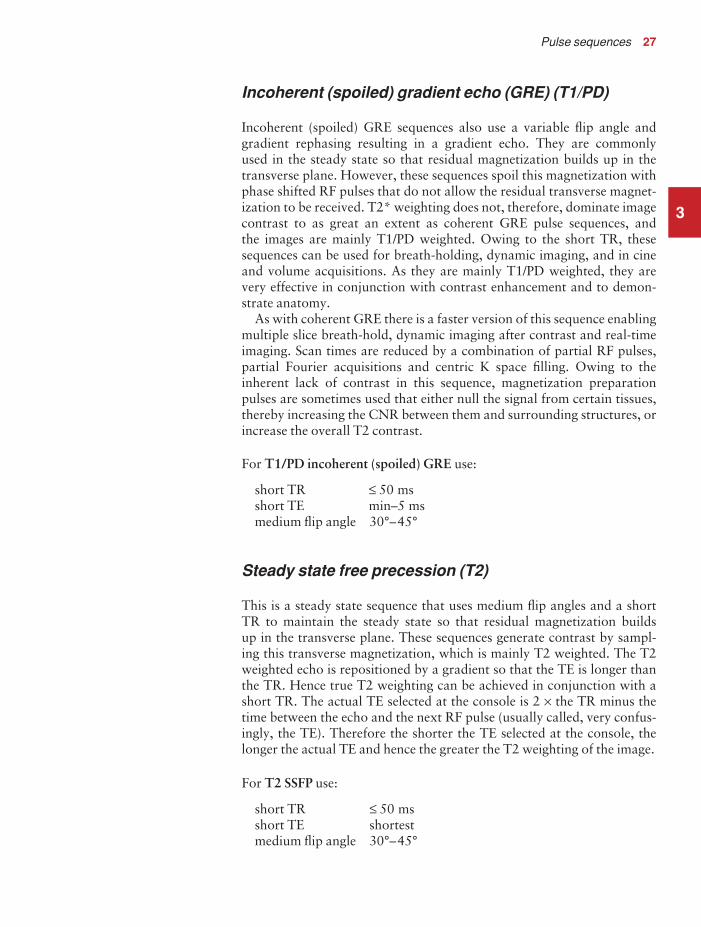
Incoherent (spoiled) gradient echo (GRE) (T1/PD)
Incoherent (spoiled) GRE sequences also use a variable flip angle and gradient rephasing resulting in a gradient echo. They are commonly used in the steady state so that residual magnetization builds up in thetransverse plane. However, these sequences spoil this magnetization withphase shifted RF pulses that do not allow the residual transverse magnet-ization to be received. T2* weighting does not, therefore, dominate imagecontrast to as great an extent as coherent GRE pulse sequences, and the images are mainly T1/PD weighted. Owing to the short TR, thesesequences can be used for breath-holding, dynamic imaging, and in cineand volume acquisitions. As they are mainly T1/PD weighted, they arevery effective in conjunction with contrast enhancement and to demon-strate anatomy.
As with coherent GRE there is a faster version of this sequence enablingmultiple slice breath-hold, dynamic imaging after contrast and real-timeimaging. Scan times are reduced by a combination of partial RF pulses,partial Fourier acquisitions and centric K space filling. Owing to theinherent lack of contrast in this sequence, magnetization preparationpulses are sometimes used that either null the signal from certain tissues,thereby increasing the CNR between them and surrounding structures, orincrease the overall T2 contrast.
For T1/PD incoherent (spoiled) GRE use:
short TR ≤ 50 msshort TE min–5 msmedium flip angle 30°–45°
Steady state free precession (T2)
This is a steady state sequence that uses medium flip angles and a short TR to maintain the steady state so that residual magnetization builds up in the transverse plane. These sequences generate contrast by sampl-ing this transverse magnetization, which is mainly T2 weighted. The T2weighted echo is repositioned by a gradient so that the TE is longer thanthe TR. Hence true T2 weighting can be achieved in conjunction with ashort TR. The actual TE selected at the console is 2 × the TR minus thetime between the echo and the next RF pulse (usually called, very confus-ingly, the TE). Therefore the shorter the TE selected at the console, thelonger the actual TE and hence the greater the T2 weighting of the image.
For T2 SSFP use:
short TR ≤ 50 msshort TE shortestmedium flip angle 30°–45°
3
9781405160858_4_003.qxd 28/05/2008 15:17 Page 27

28 Handbook of MRI Technique
Echo planar imaging (EPI)
Echo planar imaging (EPI) sequences fill all of K space in one repetition(called single shot) or multiple repetitions (called multi-shot) by usingvery long echo trains. Echoes are produced by alternating the frequencyencoding gradient and therefore the echoes that fill K space are gradientechoes (if the echoes are spin echoes resulting from repeated applicationof a 180° rephasing pulse the sequence is called FSE). EPI sequences aregiven terms depending on what precedes the EPI filling of K space. If thesequence begins with a 90°/180° combination this is called SE-EPI. If thesequence begins with a 180°/90°/180° combination this is called IR-EPI. If the sequence begins with a single RF excitation pulse of any flip angle(i.e. there is no 180° RF rephasing pulse) it is called a GE-EPI.
If all of K space is filled in one go, this is termed single shot EPI (SS-EPI).SS-EPI produces images much more rapidly than SS-FSE as it uses a trainof gradient echoes rather than spin echoes and can therefore fill K space ina fraction of a second. However, SS-EPI sequences are very prone to arte-facts such as chemical shift, distortion and blurring. These artefactsincrease relative to the echo spacing and therefore the time of the echotrain. For this reason EPI sequences are often used in multi-shot modewhere a quarter or a half of K space is filled per TR period thereby reduc-ing the time of the echo train. This can also be minimized by implement-ing any, or all, of the following:
• increasing the FOV• increasing the receive bandwidth• reducing the frequency encoding matrix• reducing the phase FOV.
EPI, BGRE and the fast versions of both coherent and incoherent(spoiled) GRE sequences currently represent the fastest acquisition modesin MRI. Real-time, dynamic and functional studies are possible using thistechnique. Some of these are discussed in Part 2 and are therefore summar-ized here.
• Real-time imaging: Very fast sequences, such as EPI, permit real-time imaging of moving structures. This is proving to be very usefulin interventional procedures where a biopsy needle, laser probe orother instrument can be visualized in real-time. Biopsies, thermalablations of tumours, angioplasties, endoscopies and limited-fieldsurgical operations are the most promising applications of thistechnique (see also Dynamic imaging below).
• Dynamic imaging: Dynamic imaging refers to the rapid acquisitionof images either after contrast enhancement, or to observe move-ment. It may be utilized to visualize the motion of a joint (e.g. aknee), or a structure such as the cervical spine or pelvic floor. Singleimages may be obtained using GRE or EPI sequences in variousdegrees of motion. Alternatively multiple slices can be acquiredeither to cover more anatomy, or to visualize the structure in many
3
9781405160858_4_003.qxd 28/05/2008 15:17 Page 28

Pulse sequences 29
positions during data acquisition. When used with EPI, acquisi-tions in the order of 20 images per second are possible and there-fore these techniques are termed real-time. If used in conjunctionwith GRE sequences, however, data acquisition is much slower andtherefore these techniques are termed quasi real-time. Dependingon the temporal resolution of the structure under examination,quasi real-time techniques may not always provide an accurate rep-resentation of motion. Used in conjunction with contrast enhance-ment, dynamic imaging visualizes the speed of uptake of contrast,which may be necessary to determine the nature of a lesion. This is termed perfusion imaging (see also Brain in Part 2). It can be usedin many areas including the brain, pancreas, liver and prostate. One of the most important applications of dynamic imaging is in the breast where contrast enhancement is useful to characterize a lesion. Benign lesions take longer to enhance than malignantlesions, and scar tissue may not enhance at all. As gadolinium is given, a T1 sequence is required and, due to the dynamic natureof the series, the acquisition times must be as short as possible.Incoherent (spoiled) GRE or FSE sequences are therefore ideal for this type of examination. The entire breast, rather than only afew slices through a lesion, can be demonstrated (some systemsnow have ultrafast volume acquisition available). This method isobviously important if multi-focal disease is suspected. Tissue char-acterization by measuring uptake of contrast is also a useful tech-nique in the prostate.
• Functional imaging (fMRI): Functional imaging (fMRI) is a rapidtechnique that acquires images of the brain during activity or stimulus and at rest. The two sets of images are then subtracteddemonstrating functional brain activity as a result of increasedblood flow to the activated cortex. The mechanism responsible for contrast in functional imaging is termed BOLD (blood oxygena-tion level dependent), which exploits the differences in magneticsusceptibility between oxy- and deoxyhaemoglobin. This results in an increased signal intensity in activated areas of the cortex thathave lower levels of deoxyhaemoglobin than inactivated areas. Thehigh signal is then overlaid on to anatomical images. FunctionalMRI is useful to evaluate brain activity in a whole range of dis-orders including epilepsy, stroke and behavioural problems.
• Diffusion weighted imaging (DWI): Diffusion weighted imaging(DWI) demonstrates areas with restricted diffusion of extracellularwater such as infarcted tissue. In normal tissue, extracellular waterdiffuses randomly whereas in ischaemic tissue, cells swell andabsorb water thereby reducing average diffusion. In DWI thesequence can be sensitized to diffusion by applying equal gradientson each side of a 180° RF pulse. Hence diffusion weighted imagesare most effectively acquired using SE type sequences such as SE orSE-EPI. These gradient pulses are designed to cancel out the phaseshift of stationary spins whilst moving spins experience a phase
3
9781405160858_4_003.qxd 28/05/2008 15:17 Page 29

30 Handbook of MRI Technique
shift. Therefore signal attenuation occurs in normal tissue with random motion and high signal appears in tissues with restricteddiffusion. The amount of attenuation depends on the amplitude of the gradients which is altered by selection of a b-value (expressedas s/mm2). Gradient pulses can be applied along the X, Y and Z axesto determine the axis of restricted diffusion. The term isotropic diffusion is used to describe diffusion gradients applied in all threeaxes. DWI is mainly useful in the brain to differentiate salvageableand non-salvageable tissue after stroke. It is also useful in the liver,prostate, spine and bone marrow.
• Perfusion imaging: Perfusion imaging refers to the microscopicchanges in perfusion when gadolinium first passes through the capillary bed. Mainly used in the brain to assess perfusion kinetics,the MR sequence is sensitized to the very transient changes in T2*as a bolus of contrast first passes through the capillary bed of the area under investigation. Therefore GRE sequences are alwaysused and typically SS-GE-EPI is common. Images are acquired very rapidly before, during and after an injection of a small bolus ofcontrast in the ante-cubital fossa. Images are then post-processedand perfusion graph and haemodynamic images are produced.
Magnetic resonance angiography (MRA)
The principle of magnetic resonance angiography (MRA) is to acquireimages where the signal returned from flowing nuclei is high, and the sig-nal from stationary nuclei is low. In this way contrast between vessels andbackground tissue is achieved. There are several techniques available toobtain this contrast. Black-blood imaging combines SE or FSE sequenceswith spatial presaturation pulses to produce images in which flowing vessels appear black. High signal seen in this type of sequence may indic-ate stenosis or occlusion of the vessel (see Flow phenomena and artefacts).Bright-blood imaging combines GRE sequences with GMN to produceimages where flowing vessels are bright. A signal void seen in this type ofsequence may indicate either a stenosis or occlusion of the vessel (see Flowphenomena and artefacts).
There are additional techniques designed especially for angiography.Both allow for data acquisition in either sequential (2D) or volume (3D)mode. Each has its own advantages and disadvantages and therefore eachis used for different purposes. The two types of MRA are summarizedbelow. These are time of flight (TOF) and phase contrast (PC).
• Time of flight (TOF): This usually uses an incoherent (spoiled)GRE sequence in conjunction with TR and flip angle combinationsthat saturate background tissue, but allow moving spins to enterthe slice/volume fresh and therefore return a high signal. Spatialpresaturation pulses placed between the origin of flow and the FOV saturate moving spins entering the FOV, thereby improv-ing visualization of either arterial or venous circulation. Thesepulses are often concatenated in 2D acquisitions so that the spatial
3
9781405160858_4_003.qxd 28/05/2008 15:17 Page 30

Pulse sequences 31
presaturation pulse is applied around each slice in the stack, asopposed to the whole set of slices. This strategy improves the effici-ency of presaturation. Unwanted signal is sometimes generated bytissues that have very short T1 recovery times (such as fat), as theyrecover some of their longitudinal magnetization between each RFpulse and therefore produce signal. Spectral/chemical presatura-tion pulses, imaging with a TE that collects the echo when fat andwater are out of phase with each other, and utilizing magnetizationtransfer (MT) contrast, commonly reduce this problem. In volumeimaging, flowing spins often become saturated by the RF pulses,thereby reducing their signal. This problem can be minimized bythe implementation of ramped flip angles, which initially use smallflip angles, and then gradually increase them incrementally duringdata acquisition. In this way the saturation of flowing nuclei isdelayed, therefore maintaining vessel signal. In 2D acquisitions,however, TOF-MRA provides good vessel contrast as nuclei arenot usually present in the slice long enough to become saturated.Common applications are to demonstrate venous and arterial flowin the head, neck and peripheral vessels.
For 2D TOF-MRA use: For 3D TOF-MRA use:
TR 28–45 ms TR 25–50 msFlip angle 40°–60° Flip angle 20°–30°TE minimum TE minimum
Phase contrast (PC): This usually uses a coherent GRE sequenceacquired both with, and without, a bipolar gradient pulse. The phaseacquired by flowing spins as a result of the application of the bipolargradient is used to produce images based on subtraction. Sensitivityto flow velocity is controlled by a parameter called velocity encod-ing or VENC, which can be applied in one, or all three orthogonalplanes. PC-MRA provides excellent background suppression andavoids intra-slice/slab flow saturation. However, the scan timesassociated with PC-MRA are often very long as the scan time isdependent not only on the TR, matrix size and NEX/NSA, but alsoon the number of flow encoded axes. Common applications are todemonstrate arterial flow in the head and major vessels.
For 2D and 3D PC MRA use:
TR 25–33 msFlip angle 20°TE minimumVENC 20–40 cm/s for venous flow,
increase up to 60 cm/s for arterial flow
• Contrast enhanced MRA (CE-MRA): This is a technique thatinvolves injecting a small amount of gadolinium or a similar agentinto the ante-cubital fossa and scanning an area of the patient to
3
9781405160858_4_003.qxd 28/05/2008 15:17 Page 31

32 Handbook of MRI Technique
visualize the contrast enhanced vessels. Usually the timing is suchthat the arterial supply is seen but scans may be delayed slightly tovisualize venous structures. In arterial imaging, the sequences usedmust be rapid ones to enable accurate visualization in the arterialphase. Typically T1 weighted GRE sequences are used as they provide the optimum combination of speed, image quality and con-trast. If the ROI is in the chest and abdomen, the patient is usuallyrequired to hold his or her breath during acquisition. CE-MRA hasan advantage over conventional MRA techniques in that vesselvisualization is not as susceptible to flow and directional effects and is thought to be more accurate. However it does involve aninjection of contrast media. Renal, carotid and peripheral arteriesare commonly examined with this technique.
• Magnetization transfer (MT) contrast: Magnetization transfer(MT) is a technique that is commonly used to suppress backgroundtissue thereby enhancing the conspicuity of vessels and certain dis-ease processes. Its function is based on the relaxation differences
3
Table 3.2 Summary of the contrast characteristics of pathology and normal anatomy
High signal
Low signal
No signal
T2
CSFSynovial fluidHaemangiomaInfectionInflammationOedemaSome tumoursHaemorrhageSlow-flowing bloodCysts
Cortical boneBone islandsDeoxyhaemoglobinHaemosiderin CalcificationT2 paramagnetic agents
T1 and T2
AirFast-flowing blood
LigamentsTendons
Cortical boneScar tissueCalcification
T1
FatHaemangiomaIntra-osseous lipomaRadiation changeDegenerative fatty depositionMethaemoglobinCysts with proteinaceous fluidParamagnetic contrast agentsSlow-flowing blood
Cortical boneAVNInfarctionInfectionTumoursSclerosisCystsCalcification
9781405160858_4_003.qxd 28/05/2008 15:17 Page 32

Pulse sequences 33
between water protons in different environments. Water protonsbroadly fall into two categories: those that are free, and those thatare bound to surrounding immobile macromolecules. MT involvesthe exchange of magnetization between the free and bound waterprotons. Presaturation off-resonant pulses applied just before theRF excitation pulse saturate the bound protons and promote anexchange of some of this saturated magnetization on to the freeprotons. This pulse is designed to excite hydrogen protons inmacromolecules such as proteins. These relatively large moleculeshave a very short T2 and usually do not contribute to the MRimage. With the MT pulse, however, some of these spins transfertheir magnetization to the more mobile water spins. This results in a reduced signal return from the free protons. For example, greyand white matter loses 30–40% of its signal when an MT pulsesequence is utilized. The common uses of MT are to increase theconspicuity of certain disease processes such as multiple sclerosis,haemorrhage and AIDS, and to improve vessel contrast in TOF-MRA images by suppressing background tissue.
Conclusion
The choice of pulse sequence is usually the first decision made by eitherthe radiologist or practitioner as it determines the weighting and contrastcharacteristics of the image. Table 3.2 summarizes the contrast character-istics of pathology and normal anatomy. Careful consideration of theimage quality and the required scan time parameters is also necessary to achieve the optimum examination. The flow and artefact phenomenacommon to the area under examination must also be taken into account,as some compensation techniques may compromise the pulse sequencechosen. These phenomena are discussed in the next section.
3
9781405160858_4_003.qxd 28/05/2008 15:17 Page 33

4
Flow phenomena
Introduction
This section refers mainly to the Artefact problems subheading discussedunder the Image optimization heading considered for each examina-tion in Part 2. The most common flow phenomena are summarized inTable 4.1. Only a brief overview is provided here. For a more detailedexplanation please refer to Chapter 6 of MRI in Practice or an equivalenttext.
The most common types of flow phenomena are:
• time of flight (TOF) (not to be confused with TOF MRA)• entry slice phenomenon• intra-voxel dephasing.
4 Flow phenomena andartefacts
34
9781405160858_4_004.qxd 28/05/2008 15:17 Page 34

Flow phenomena and artefacts 35
4
Table 4.1 Artefacts and their remedies
Artefact
Truncation
Phase mismapping
Chemical shift
Chemical misregistration
Aliasing
Zipper
Magnetic susceptibility
Shading
Cross talk
Cross excitation
Remedy
Increase phase encodingsUse more than oneNEX/NSA
Respiratory compensationGatingPresaturationGradient moment nullingImmobilize patientUse antispasmodic agentSedation
Increase bandwidthReduce FOVUse chemical saturation
Set TE at multiple ofperiodicity
Over-sampling (frequency)Over-sampling (phase)
Enlarge FOV
Call engineer
Use spin echoRemove metal wherepossible
Load coil properly
None
Interleaving of sliceacquisitionSquaring off of RF pulses
Penalty of remedy
Increases scan timeIncreases scan time
May lose slicesTR variableMay lose slicesIncreases minimum TENoneCostly, invasiveInvasive, requires monitoring
Decreases TEReduces SNRReduces SNR
None
NoneNone or increase in scan timedepending on systemReduces resolution
Irate engineer!
Not flow sensitiveNone
None
None
Doubles the scan time
Reduces SNR
9781405160858_4_004.qxd 28/05/2008 15:17 Page 35

36 Handbook of MRI Technique
Time of flight (TOF)
Time of flight (TOF) phenomenon occurs because nuclei that movethrough the slice may receive only one of the RF pulses applied. In GREsequences the gradient rephasing is not slice selective, so nuclei producesignal as long as they have been excited at some point and are rephased by the gradient. In a SE sequence, a nucleus may receive the excita-tion pulse but then exit the slice before the 180° rephasing pulse can beapplied. Conversely, it may not be present in the slice when the excitationpulse is applied, and then enter the slice to receive only the 180° pulse.Under these circumstances the nucleus does not produce a signal. In SEsequences, TOF effects cause either a signal loss or signal enhancementfrom flowing nuclei, and they are compensated for by using presaturationpulses placed between the origin of the flow and the FOV.
Entry slice phenomenon
This phenomenon depends on the excitation history of nuclei flowingwithin a vessel, and is largely controlled by the direction of flow relative toslice excitation. Nuclei that flow in the same direction as slice excitationreceive several RF excitation pulses and quickly become saturated. Nucleithat flow in the opposite direction to the slice excitation do not experiencerepeated RF excitation pulses, as they are always entering the selectedslice ‘fresh’. They are, therefore, not saturated as quickly as nuclei flowingin the same direction as slice excitation. These phenomena result in a dif-ference in signal between arteries and veins where flow is perpendicular tothe slice plane, and is most prominent in the first and last slices of theimaging stack. Entry slice phenomenon is compensated for by using pre-saturation pulses placed between the origin of the flow and the FOV.
Intra-voxel dephasing
This is caused by the presence of gradients that either accelerate or decel-erate flowing nuclei as they move from areas of differing field strengthalong the gradient. As a result of this acceleration or deceleration, theflowing nuclei either gain or lose phase relative to their stationary coun-terparts. This phase difference between stationary and flowing nuclei inthe same voxel causes dephasing and a signal loss. Intra-voxel dephasingis compensated for by using gradient moment nulling (GMN).
4
9781405160858_4_004.qxd 28/05/2008 15:17 Page 36

Flow phenomena and artefacts 37
Flow artefact remedies
The two main remedies of flow-related artefacts are:
• spatial presaturation pulses• gradient moment nulling (GMN).
Spatial presaturation: nullifies signal from nuclei that produce un-wanted signal or artefact by applying a 90° RF pulse to selected tissuebefore the pulse sequence begins. Therefore, the magnetic moments ofthese nuclei are inverted to 180° by the excitation pulse and return no sig-nal. Presaturation pulses may also be delivered at the specific precessionalfrequency of either fat or water to nullify signal from these types of tissue.This technique, which is called chemical/spectral presaturation, either util-izes a 90° saturation pulse as described above, or the pulse has a greatermagnitude and inverts the magnetization in the tissue as in inversionrecovery pulse sequences (see Pulse sequences). Chemical presaturationcan be used to distinguish between fat and enhancing pathology in T1weighted sequences and in FSE T2 weighted sequences where fat andpathology are often isointense.
Spatial presaturation:
• produces low signal from flowing nuclei;• reduces motion and aliasing if bands are placed over signal-
producing anatomy;• increases the specific absorption rate (SAR) and may reduce the
slice number available per TR;• mainly reduces time of flight and entry slice phenomena.
Gradient moment nulling (GMN): utilizes extra gradients to rephasethe magnetic moments of flowing nuclei so that they have a similar phaseto their stationary counterparts.
GMN:
• produces high signal from flowing nuclei;• increases the minimum TE and may reduce the slice number
available;• mainly reduces intra-voxel dephasing.
Both GMN and spatial presaturation decrease flow artefact seen on animage, but are also valuable in reducing phase mismapping and motionartefact.
4
9781405160858_4_004.qxd 28/05/2008 15:17 Page 37

38 Handbook of MRI Technique
Artefacts
Introduction
This section also refers mainly to the Artefact problems subheading discussed under the Image optimization heading considered for eachexamination in Part 2. The most common artefacts are summarized inTable 4.1. Only a brief overview is provided here. For a more detailedexplanation please refer to Chapter 7 of MRI in Practice or an equivalenttext.
The most common types of artefact seen in MR images are:
• phase mismapping (motion)• aliasing (wrap)• chemical shift• chemical misregistration• truncation• magnetic susceptibility.
Phase mismapping
Phase mismapping or ghosting is caused by anatomy moving betweeneach application of the phase encoding gradient, and by motion along thephase encoding gradient during the acquisition of data. Pulsatile motionof vessels, movement of the chest wall during respiration and cardiacmotion are the most common sources of this artefact. Involuntary move-ment such as cardiac motion also causes phase mismapping. Tips toreduce voluntary motion are discussed under Patient care and safety.
Phase mismapping is reduced by one or more of the following:
• swapping the phase axis so that the artefact does not interfere withthe area under examination (only moves the artefact);
• placement of spatial presaturation pulses between the origin of theartefact and the FOV;
• using respiratory compensation (RC) (see Gating and respiratorycompensation techniques);
• using echocardiogram (ECG) gating or peripheral (Pe) gating (seeGating and respiratory compensation techniques).
• selecting GMN.
Aliasing
Aliasing occurs when anatomy that lies within the boundaries of thereceiver coil (and therefore produces signal) exists outside the FOV. If the data from the signal received are under-sampled by the system, there isa duplication of frequency and phase values so that anatomy that exists
4
9781405160858_4_004.qxd 28/05/2008 15:17 Page 38

Flow phenomena and artefacts 39
outside the FOV is allocated a pixel position within the FOV. This anat-omy is therefore ‘wrapped’ into the image.
Aliasing can occur along both the frequency encoding axis (frequencywrap) and the phase encoding axis (phase wrap). Frequency wrap islargely eliminated with the use of digital filters that filter out signal ori-ginating outside the FOV. Phase wrap is reduced by:
• increasing the FOV to the boundaries of the coil;• over-sampling in the phase direction;• placing spatial presaturation pulses over signal-producing anatomy.
Chemical shift
Chemical shift artefact is caused by the dissimilar chemical environmentsof fat and water. This results in a precessional frequency difference betweenthe magnetic moments of fat and water and is called chemical shift. Itsmagnitude significantly increases at higher field strengths. Chemical shiftartefact causes a displacement of signal between fat and water along thefrequency axis. It is reduced by:
• scanning with a low field-strength magnet;• removing either the fat or water signal by the use of STIR/chemical/
spectral presaturation, the Dixon technique (see Chemical misregis-tration below);
• broadening the receive bandwidth;• reducing the size of the FOV.
Chemical misregistration
Chemical misregistration is also caused by the difference in precessionalfrequency between fat and water. However, this occurs because as fat andwater are precessing at different frequencies, they are in phase with eachother at certain times and out of phase at others. When the signals fromboth fat and water are out of phase, they cancel each other out so that signalloss results. This artefact mainly occurs along the phase axis and causes a dark ring around structures that contain both fat and water. It is mostprevalent in GRE sequences and it can be used positively to reduce the signal from fat (Dixon technique). To reduce chemical misregistration:
• Use SE or FSE pulse sequences.• Use a TE that matches the periodicity of fat and water so that the
echo is generated when fat and water are in phase. The periodicitydepends on the field strength (approximately 4.2 ms at 1.5 T and 7ms at 0.5 T). The Dixon technique involves selecting a TE at halfthe periodicity so that fat and water are out of phase. In this waythe signal from fat is reduced. This technique is mainly effective inareas where water and fat co-exist in a voxel.
4
9781405160858_4_004.qxd 28/05/2008 15:17 Page 39

40 Handbook of MRI Technique
Truncation
This is caused by under-sampling of data at the interface of high and lowsignal. It occurs along the phase axis and produces a dark band runningthrough a high signal area. It is most commonly seen in the cervical cord,where it is specifically known as Gibbs artefact. Truncation is mainlyreduced by increasing the number of phase encoding steps.
Magnetic susceptibility
Magnetic susceptibility artefact occurs because all tissues magnetize to a different degree depending on their magnetic characteristics. This pro-duces a difference in their individual precessional frequencies and phase.The phase discrepancy causes dephasing at the boundaries of structureswith a very different magnetic susceptibility, and signal loss results. It is commonly seen on GRE sequences when the patient has a metal prosthesis in situ but is also visualized at the interface of the petrous boneand the brain on coronal incoherent (spoiled) GRE images. Magnetic sus-ceptibility can be used advantageously when investigating haemorrhageor blood products, as the presence of this artefact suggests that bleedinghas recently occurred. Magnetic susceptibility is reduced by:
• using SE or FSE pulse sequences;• removing all metal items from the patient before the examination.
Conclusion
The main artefacts encountered in MRI are described here. In addition,phase artefact caused by pulsation of great vessels, CSF flow and cardiacand respiratory motion are compensated for by using appropriate soft-ware and these are discussed in the next section. Table 4.1 summarizesartefacts and how they may be remedied.
4
9781405160858_4_004.qxd 28/05/2008 15:17 Page 40

5Introduction
This section refers to the mechanisms and correct placement of gatingleads and respiratory bellows. The basic concepts of these techniques aresummarized below. Only a brief overview is provided here. For a moredetailed explanation please refer to Chapter 8 of MRI in Practice or anequivalent text.
Cardiac gating (ECG gating)
Cardiac gating uses the electrical signal detected by leads placed on to thepatient’s chest to trigger each RF excitation pulse. In this way, each imageis always acquired at the same phase of the cardiac cycle, so that phasemismapping from cardiac motion is reduced. There are several factors totake into account when using cardiac gating.
Lead placement
There are usually four leads that are colour coded for easy use. Some sys-tems may only use three leads. In addition, not all systems use the samecolour coding but the principle of their placement is the same. Leads canbe placed either anteriorally on the chest, or posteriorly on the patient’sback. Anterior placement is usually simpler as the landmarks are easier tofind. In addition if the leads are placed posteriorly, the patient lies on themduring the examination, which may be uncomfortable. The anterior leadplacement is described here but if the trace on the ECG monitor is poor,the leads can be placed posteriorly in a mirror image to the anterior leads.
5 Gating and respiratorycompensation techniques
41
9781405160858_4_005.qxd 28/05/2008 15:18 Page 41

42 Handbook of MRI Technique
This may improve the trace. Lay the patient supine on the examinationcouch. The patient wears a front opening gown for easy access. The leadstickers are then firmly attached to the patient’s skin. The leads are usuallycolour coded thus:
• black• white• red (live)• green (ground or earth).
The white and the red leads are placed across the heart, as the voltagedifference between the two produces the ECG trace. The green lead ispositioned as close as possible to, but not touching, the red lead as thisacts as a ground. The black lead also acts as ground. Some systems maynot have colour coding, but directions on lead placement are usually givenby the manufacturer. Leads can be placed in a variety of ways as long asthe above criteria are met. Described below is the simplest method of leadattachment (Figure 5.1):
• Black lead right upper chest below the clavicle• White lead in the midline on the superior aspect of the sternum• Red lead one intercostal space directly inferior to the left nipple• Green lead lateral to the red lead but not touching it.
The black lead may be omitted if it is not available on the system. Oncethe leads are attached and plugged into the system, check that the ECGtrace is satisfactory. Traces vary according to rate, rhythm and cardiacoutput. These in turn depend on the activity of the heart, which is oftenaltered by certain disease processes. Arrhythmias and poor cardiac output(which may be why the patient is being examined) are common problems.The signs of a good trace are:
5
Figure 5.1 The correctplacement of gating leads.
9781405160858_4_005.qxd 28/05/2008 15:18 Page 42

Gating and respiratory compensation techniques 43
• a regular rate – the PQRST complexes are spaced evenly apart;• the R wave is significantly larger than the T wave;• the PQRST complex has good amplitude (Figure 5.2).
If the trace is satisfactory, the patient is placed within the magnet bore.This action frequently alters the trace, and often does so to such an extentthat the trace is no longer acceptable. The commonest problem is an eleva-tion of the T wave so that the system cannot distinguish it from the Rwave. If this occurs, or if the original trace is unsatisfactory, several meas-ures can be taken.
How to improve the trace
• Always ensure that the electrodes are firmly attached to the chestwall. In male patients, shave any chest hair in the region of the electrodes and clean the skin with alcohol. This removes grease thatmay prevent proper attachment. After the skin is dry, the electrodesare attached.
• Make sure that the leads are firmly attached to the stickers in thecorrect order.
• The leads may be swapped around or placed posteriorly to improvethe trace. Initially, swap the black and the white leads or the redand the green leads. If this fails to improve the trace, try any othervariation of lead placement.
• Place the patient inside the magnet feet first. Patients are usuallypositioned head first into the magnet for examinations of the chest;however placing them feet first is often beneficial, especially if theproblem is an elevated T wave.
• Movement of the cable leads causes irregularities of the trace.Ensure that they are immobilized (see Cable safety below), and thatthe patient does not touch them during the examination. In addi-tion coughing or sneezing can interrupt the trace, so ask the patientto try not to move during the acquisition of data.
5
Figure 5.2 A normal ECGtrace and the correct placementof the triggering thresholdrelative to the R wave.
9781405160858_4_005.qxd 28/05/2008 15:18 Page 43

44 Handbook of MRI Technique
• Change to peripheral gating or pseudogating (dispensing with gat-ing and setting a TR that is equal to the RR interval).
If after all these measures are taken the trace is still poor, the problemcould be a faulty monitor or software problem. Gating is often unreliableand there are occasions when the operator has to make do with the tracedisplayed. In our experience awful traces can lead to excellent images, andvice versa.
Cable safety
The cables that connect the leads to the system are conductors and aretherefore capable of carrying considerable current. During the examina-tion, the majority of the cables lie within the RF field and therefore highcurrents are induced within them. This current potentially results in thecables storing and transmitting heat to the patient. Although every cableis heavily insulated, a build-up of heat is possible, and this can causeminor burns if the cables are in direct contact with the skin. In addition if the insulation is damaged, high currents could be transmitted to thepatient. To avoid this:
• Check the cable insulation for damage at regular intervals, not justwhen gating is required. If they are frayed or split do not, under anycircumstances, use them.
• When positioning the cables, avoid looping and cross-over as theirpoint of contact induces additional heat.
• Ensure that the cables do not touch the bore when the patient isinside the magnet. Run the cables down the middle of the patient.Looping them over the patient’s foot prevents them from slippingto the side during the examination.
• Place foam pads between the cables and the patient’s chest, andensure that there is a layer of gown or blanket between the cablesand the patient’s skin.
• Tape the cables and pads to the side of the table. This ensures thatthey cannot slip out of place during the examination. In addition,this prevents movement of the cables that can interfere with thetrace.
Peripheral gating (Pe gating)
Peripheral gating uses a photo sensor attached to either a finger or toe to detect the increase in volume in the capillary bed during systole. Thisaffects the amount of light returned to the sensor and a waveform is produced. The waveform does not have the characteristics of the ECGtrace, but the peaks of the waves approximately correspond to the R wave(about 250 ms after the R wave). This waveform is displayed on the monitor. A good trace has:
5
9781405160858_4_005.qxd 28/05/2008 15:18 Page 44

Gating and respiratory compensation techniques 45
• equally spaced peaks• significant amplitude.
If the trace is unsatisfactory:
• Ensure that the photo sensor is firmly attached with the light sourceadjacent to the skin.
• Ensure the finger or toe is warm and well perfused. Placing it inwarm water or rubbing it is often beneficial.
• Swap the sensor to the left hand as the left arm receives arterialblood directly from the aorta (rather than through the innominateartery) and sometimes has a larger pulse.
Gating parameters
For T1 weighting and ECG/Pe gating use 1 R to R interval.
For PD/T2 weighting and ECG/Pe gating use 2 or 3 R to R intervals.
Note: Other parameters used for gating depend on the system. How-ever, the following usually suffice:
Trigger window 15% of the R to R interval.
Delay after trigger minimum permissible to allow maximum slice number.
Slices are usually acquired evenly across the available imaging time,although cardiac motion is sometimes reduced if slice acquisition isdelayed until diastole.
Cine imaging
Cine, balanced GRE and coherent GRE are beneficial to visualize heartfunction, blood flow and heart wall motion. For example, the restrictionof flow through a coarctation or poorly functioning valve in the heart can be clearly visualized using cine. Good contrast between flowing bloodand surrounding lung or cardiac tissue is important. Therefore the imple-mentation of a steady state sequence that enhances the signal intensity of blood is necessary. In addition, the application of GMN in coherentGRE and the balanced gradients in balanced GRE not only reduces flowartefact, but also increases the signal from flowing blood thereby improv-ing CNR.
The efficiency of cine is mainly governed by the correct selection of the number of cardiac phases acquired for each slice during the TR. Dataacquisition (data points) should coincide as closely as possible to thesephases. If the system cannot match each phase with a data point, cineimaging is less efficient.
5
9781405160858_4_005.qxd 28/05/2008 15:18 Page 45

46 Handbook of MRI Technique
Unfortunately, cine images are often plagued with artefact. If com-patible, RC effectively reduces respiratory ghosting. Alternatively, breath-holding single slice coherent GRE images eliminate respiratory motion.Susceptibility and misregistration artefacts are common due to gradientrephasing in GRE sequences. Reducing the TE decreases susceptibilityproblems, and selecting a TE when fat and water are in phase minimizesmisregistration.
Respiratory compensation (RC)
There are many forms of respiratory compensation including:
• breath-holding (patient holds their breath during the acquisition);• navigators (a ROI is placed over the diaphragm and the system
throws out data that coincide to maximum chest wall motion);• respiratory triggering (acquisition of data is limited to minimum
chest wall motion);• respiratory compensation (RC) (phase encodings and therefore K
space lines filled are re-ordered during the acquisition to minimizeartefact).
The latter two techniques are achieved by placing expandable air-filledbellows around the patient’s chest. The movement of air back and forthalong the bellows during inspiration and expiration is converted to awaveform by a transducer. In RC the system then orders the phase encod-ing gradients so that the steep slopes occur when maximum movement of the chest wall occurs, and reserves the shallow gradient slopes for minimum chest wall motion. In this way most of the signal is acquiredwhen the chest wall is relatively still and therefore phase ghosting isreduced. Respiratory triggering is sometimes not as efficient as RC atreducing artefact but does have the advantage of being compatible withphase reordering sequences such as FSE. The success of respiratory bel-lows depends on the following:
• Ensure that there is no vacuum within the bellows as this inhibitsthe back and forth movement of air during respiration. This mayentail disconnecting the bellows in between examinations and ensur-ing that they are kept on the ground until they are reattached. Thisguarantees that no air pockets collect in the bellows or connectingtubing. Some systems, however, require that you do not disconnectthe bellows. Please refer to the manufacturer’s specifications.
• Place the bellows so that the corrugating portion lies over the anterior chest wall.
• Place the bellows diagonally across the chest and upper abdomen.This ensures that the bellows ‘catch’ both thoracic and abdominalmovements during respiration (Figure 5.3).
• Attach the bellows firmly. The bellows must be tight enough so that movement of the corrugated portion can be seen clearly during
5
9781405160858_4_005.qxd 28/05/2008 15:18 Page 46

Gating and respiratory compensation techniques 47
quiet respiration. However, if the bellows are too tight, the patientmay become uncomfortable.
• Ensure that the bellows are firmly plugged into the transducer.• If the images show large amounts of respiratory mismapping, or the
system informs you that compensation is not working adequately:
• Check that the bellows have not become loose or unattached.• Ask the patient to breathe quietly. Uneven breaths can confuse
the system.
• If the patient is small or a child, the bellows may not fit snugly andtherefore their action can be compromised. Foam pads placedbetween the bellows and the patient are usually beneficial.
Conclusion
Gating and respiratory compensation are commonly utilized to examinethe chest and abdomen, although gating also has uses in imaging thebrain, spinal cord and in cine. The correct use of these techniques canhave a profound influence on image quality. If you are unfamiliar with theuse of gating, it is often worth practising its implementation on volunteersso that all staff are prepared for its use on sick patients.
5
Figure 5.3 Correct positioningof the respiratory bellows to‘catch’ both thoracic andabdominal respiration.
9781405160858_4_005.qxd 28/05/2008 15:18 Page 47

9781405160858_4_005.qxd 28/05/2008 15:18 Page 48

6
Introduction
This section refers to the Patient considerations heading considered foreach examination in Part 2. Only a brief overview is provided here. For amore detailed explanation please refer to Chapter 10 of MRI in Practiceor an equivalent text.
Any patient motion, whether it is due to fear or discomfort, is likely todegrade the image whatever its SNR and resolution characteristics. Whena patient steps into an MRI facility he or she becomes the responsibility ofthe unit personnel. This responsibility extends from the patient’s magneticsafety and medical condition, to providing a relaxing environment and asmoothly running facility. It is essential for legal and ethical reasons toensure that all staff, including radiologists, radiographers, technologists,nurses, and clerical and ancillary personnel, are competent and are awareof their role in providing optimum patient care.
Patient safety
The main aspect of patient safety in any MRI facility is magnetic safety. Itis essential that all patients, relatives, and other medical or non-medicalpersonnel are prevented from entering the magnetic field until they havebeen properly screened. Physical barriers, such as doors and large warn-ing signs, are common ways of achieving this. Clerical personnel (who are usually situated at the entrance to the unit) should be aware of who ispresent in the facility and whether they have been checked for magneticsafety. Thorough screening of each patient and anyone who is to enter thefield is extremely important. Failure to do so may result in injury or evendeath. All centres should have a proper screening policy which includeschecking for:
• pacemakers• aneurysm clips• intra-ocular foreign bodies• metal devices or prostheses• cochlear implants• spinal implants
6 Patient care and safety
49
9781405160858_4_006.qxd 28/05/2008 15:18 Page 49

50 Handbook of MRI Technique
• possibility of early pregnancy• removal of all jewellery, credit cards, money, watches, etc.
Most facilities provide a screening form that patients, relatives andother persons fill in before entering the magnetic field. This ensures thatall important questions have been addressed, and provides a record that screening has taken place. This may be very important if an accidentsubsequently occurs. Any additional items, such as unremovable jewelleryand splints, are thoroughly checked for safety before the patient and their relatives enter the magnetic field. It may be necessary to insulate theitem by placing bandages between it and the patient’s skin. If the patientor relative has any unusual prosthesis or implant such as a heart valve, itsmagnetic safety must be established before they are taken into the mag-netic field.
The safety of intra-cranial aneurysm clips has been the subject of debate for some years. Ferromagnetic clips must not be scanned. Untilrecently it was considered safe to scan non-ferromagnetic clips. How-ever, studies have shown that some non-ferromagnetic clips can be deviated by a magnetic field. The latest directive is that all clips should be tested for magnetic safety prior to insertion. If this has not been possible, non-ferromagnetic aneurysm clips are still contraindicated forMRI.
Pacemakers are still considered a contraindication to MRI in most centres as the magnetic field alters the reed switch function of the pace-maker. This can lead to arrhythmias and, in certain patients, cardiacarrest. However some cardiac centres have scanned patients with pace-makers if a decision has been made that the benefits of the scan outweighthe risks and if expert help is immediately on hand should the pacemakercease to function correctly. MR safe pacemakers have been developed butare not currently widely available. Therefore you must always assume apacemaker is unsafe.
It is usually advisable to ask the patient to change into a gown, as thisavoids the problem of ferromagnetic items inadvertently entering themagnetic field inside pockets. Either clerical, nursing or radiographic staffusually perform the magnetic screening procedure. However, it is import-ant to remember that whoever screens the patient, ultimate responsibilityfalls on the person who takes the patient into the field. It is also necessaryto appreciate that in some unshielded units, the magnetic field may extendbeyond the confines of the examination room.
There are many other aspects to patient safety within the unit. Caremust be taken when transferring patients either on to trolleys or into theexamination room. This is especially important if the patient is physicallydisabled, traumatized or in pain. Non-slip flooring, and trolleys with an adjustable height and lockable brakes, not only ensure that patients are transported in safety, but also prevent injury to unit personnel. Inaddition, any equipment that comes into contact with the patient duringthe examination must be carefully checked on a regular basis. This includesgating cables (see Gating and respiratory compensation techniques), mon-
6
9781405160858_4_006.qxd 28/05/2008 15:18 Page 50

Patient care and safety 51
itoring equipment (see Paediatric imaging in Part 2), and other devicessuch as coil holders.
The safety of coils and cables is also important (Coils under the headingEquipment in the section How to use this book), as it is not unusual forthem to heat up during the examination. Ensure that there is adequateinsulation between the coils and their cables and the patient’s skin. Smallfoam pads, sheets of paper or the patient’s gown usually suffice. In addi-tion, if patients have a metal prosthesis in situ, they may experience somewarmth or discomfort during the examination. It is important to warn the patient that this might occur and to provide them with an alarm bell toring during the study, should any problems arise. Loud gradient noise alsohas safety implications, especially if the patient has very sensitive hearing.It is therefore essential to provide the patient with earplugs to preventhearing impairment. This is especially necessary when ultrafast imaging isemployed, as the gradient noise associated with these sequences oftenexceeds recommended levels.
Lastly, when EPI sequences are used, some patients have reported experiencing mild cutaneous sensations, muscle twitching and flashinglights in their eyes. This is due to the rapidly changing magnetic field. Toreduce the probability of peripheral nerve stimulation in EPI sequences,the frequency encoding direction should be R to L for all axial EPIsequences in the brain. Additionally, patients should be instructed toplace their arms by their sides and to not cross their ankles to prevent aloop that can precipitate excessive induction of current. It is advisable to warn the patient that these sensations may occur if rapid sequences are utilized. It is also necessary to provide the patient with an alarm bellduring the examination should any ill-effects occur.
Patient counselling
The emotional well-being of a patient is just as important as their physicalcondition. Many patients are not only anxious about the examination,but are also aware that the outcome of the study may affect their sub-sequent treatment and/or prognosis. Ensuring that the patient is calm and relaxed during the procedure is the responsibility of all unit per-sonnel. The clerical staff are usually the first people to come into contactwith the patient, and it is therefore important that they are welcoming and understanding of the patient’s emotional needs. A pleasant recep-tion environment further enhances a patient’s well-being. In addition, asmooth-running department, where patients are scanned at their desig-nated appointment time, nearly always reassures the patient. If the sched-ule is running late, or an emergency is fitted in, ensure that the patients are aware of the circumstances and given an approximate time for theirexamination.
Properly informed patients are usually more comfortable with theexamination than those who are fearful of the unknown. An informationleaflet sent with the appointment time is a very effective way of preparing
6
9781405160858_4_006.qxd 28/05/2008 15:18 Page 51
52 Handbook of MRI Technique
a patient for their visit to the unit. Once they have arrived, a careful explanation of the procedure including positioning, gradient noise, con-trast injections, and the approximate length of the examination is necess-ary. If equipment such as gating leads or respiratory bellows is required, the explanation is expanded to include the reasons for the use of suchaccessories, and how they may affect the patient. Any special require-ments of the patient, such as breath-holding, opening the mouth, or fixingthe eyes, must be thoroughly explained before the examination. If thepatient does not understand these requirements, the whole examinationmay be void. It is probably preferable for the radiographer/technologist to provide this explanation, as it not only establishes a relationship withthe patient, but also alerts the radiographer to specific anxieties.
When the patient is transferred into the examination room, the sight ofthe magnet bore and unfamiliar surroundings commonly increase theiranxiety. The technologist should be prepared to repeat the explanation ofthe procedure if necessary, and address any concerns that the patientmight have.
Claustrophobia is a common problem in MRI examinations. Theenclosing nature of the bore, and equipment such as the head coil, invari-ably exaggerates any claustrophobic or nervous tendencies. Listed beloware a few tips on avoiding claustrophobia:
• If the coil has a mirror, use it and make sure that it is adjusted sothat the patient can see out of the magnet.
• If possible examine the patient prone, as this often means that thepatient can see out of the magnet. This strategy is mainly beneficialwhen imaging the pelvis, abdomen, chest, and areas of the upperand lower limbs, such as femora and wrists.
• Remove the pillow under the patient’s head as this increases the distance from the patient’s face to the roof of the bore of the magnet.
• Tell the patient to close their eyes or place a piece of tissue paperover their face. Some patients dislike this, but others are comfortedby the knowledge that if they open their eyes by accident, they willbe unable to see the bore of the magnet.
• Use the bore light and fan as they increase the brightness and air circulation.
• Explain that the bore is open at both ends. These few words areoften all that is needed to reassure a patient.
• Tell the patient that they can come out of the magnet at any timeand that they may refuse the examination without disruption to thefacility. This makes the patient feel that they are in control.
• Encourage a friend or relative to accompany the patient during theexamination.
• Keep the patient informed over the system intercom of the length ofthe sequences and the progress of the examination.
• Remember to provide the patient with an alarm bell that he or shecan press to alert the radiographer/technologist during the study.
6
9781405160858_4_006.qxd 28/05/2008 15:18 Page 52

Patient care and safety 53
• If these measures fail, a successful examination is usually possibleafter sedation (see Sedation and anaesthesia in the section onPaediatric imaging in Part 2).
Using the system intercom, the radiographer/technologist updates thepatient during the study on the length of each sequence and the necessityof keeping still. It is extremely reassuring for the patient to hear a familiarvoice and to be kept informed on how the examination is progressing.This is also an opportunity to check on the well-being of the patient.There are several medical conditions that may affect how the patient ishandled in the unit. Examples of these are blindness, deafness, epilepsy,breathlessness and physical or mental disability. The imaging techniquemay have to be adapted accordingly. These, and other specific conditions,are described in more detail in Part 2. Some coils are fitted with mirrors toenable the patient to see out of the magnet bore, and it is worth remem-bering that they may also be able to see out of the examination room window and observe the technical staff at work. Therefore all unit per-sonnel should be aware that the patient may be watching their every moveand facial expression!
Patient immobilization
Careful immobilization of the patient is always necessary to ensure anoptimum study. Immobilization is especially important during lengthyexaminations and when the area under investigation is very small andoptimum spatial resolution is required. The key to good immobilization iscorrect positioning, and making the patient as comfortable as possible.Most positions assumed by the patient during an MRI study are in naturalrelaxed poses, i.e. supine with the arms at the side. However, examina-tions of the upper limb and breast often involve placing the patient pronewith their arms above their head. In addition, some medical conditionsmay preclude the use of standard positioning. Severe pain and breathless-ness are common reasons for modifying the patient’s position. It is import-ant to remember, however, that even the most comfortable positions usually become uncomfortable if the patient has to maintain them forlong periods of time.
Once the patient is placed correctly on to the examination couch andthe coils have been positioned, immobilization is then required. All manu-facturers provide foam pads of various shapes and sizes that are used to maintain a certain position. Many are moulded for use with a certaincoil. Once immobilized, it is important to ensure that the patient isrelaxed as, if effort is required to maintain the position, the likelihood of patient motion is increased. Unless the patient is in pain, it is almostimpossible to over-immobilize. It is obviously necessary, however, toensure that the patient is comfortable with the amount of immobil-ization used. Other accessories such as sticky tape are beneficial for immobilization purposes of both the patient and coils. Compression bands
6
9781405160858_4_006.qxd 28/05/2008 15:18 Page 53

54 Handbook of MRI Technique
placed across the abdomen and pelvis are very effective at reducing bowelmotion.
Other pads are useful to increase patient comfort, e.g. a small pad elevating the patient’s knees during the examination reduces back pain.
Patient after care
Once the examination is over, remove all immobilization devices, coils,straps and foam pads and carefully transfer the patient back into the waiting area. Patients are often very disorientated after an MRI study.Providing patients with a drink before they leave the unit often calmsthem, and allows the unit staff to assess their medical and emotional condition. If the patient has received sedation or anaesthesia, it is essentialthat they have fully recovered before they leave the unit (see Paediatricimaging in Part 2). Lastly, patients are usually grateful if they areinformed when to see their doctor about the results of the examination.
Conclusion
Unless the patient is very relaxed, almost any MRI examination is anordeal. Therefore the importance of patient safety and care cannot beover-emphasized. Ensuring optimum safety and counselling standards is as important as correct parameter selection. It is often difficult for medical staff to appreciate patient anxieties. The magnetic environment is second nature to unit personnel, but it is a totally new experience formost patients. Always put yourself in the patient’s shoes and volunteer to be scanned as often as possible, as this gives the best insight into thepatient’s experience.
6
9781405160858_4_006.qxd 28/05/2008 15:18 Page 54

7
Introduction
Contrast enhancement is extremely valuable in many disease processesincluding tumours, inflammation and infection. Although these patho-logies contain a high water content and are often visualized in T2weighted images, sometimes there is insufficient contrast between thelesion and surrounding tissue. In addition, T1 weighted images demon-strate a higher SNR and are therefore advantageous, but water andpathology are commonly isointense in these sequences. Therefore it issometimes necessary to selectively enhance pathology by administeringcontrast agents. This can be done either indirectly via the intravenous(IV), oral or rectal routes or directly into a structure such as a joint. Only abrief overview is provided here. For a more detailed explanation pleaserefer to Chapter 11 of MRI in Practice or an equivalent text. There aretwo types of contrast agents: those that produce positive contrast andthose that result in negative contrast.
Positive contrast agents
The most common positive contrast agent used in MRI is gadolinium(Gd). Gadolinium is a paramagnetic substance that has a relatively largemagnetic moment. When introduced into the body, its presence causesincreased fluctuations in the magnetic fields of water protons so that they tumble near to the Larmor frequency. As a result there is a transfer of energy to the surrounding lattice and both T1 and T2 relaxation timesare reduced. Since T2 relaxation is much shorter than T1, a high con-centration of agent is required to produce significant shortening of T2.However, much smaller doses are effective at shortening the T1 relaxa-tion time of water protons thereby increasing their signal intensity on T1 weighted images. Gadolinium is therefore known as a T1 enhance-ment agent.
Gadolinium is a heavy metal and binds to certain elements in the bodysuch as membranes and the osseous matrix. Therefore gadolinium cannotbe excreted unless it is attached to a chelate. This chelate surrounds thegadolinium ion and enables its excretion, mainly through the kidneys.The most common chelate in use is diethylene triaminepentaacetic acid
7 Contrast agents
55
9781405160858_4_007.qxd 28/05/2008 15:19 Page 55

56 Handbook of MRI Technique
(DTPA), which binds to eight of the nine binding sites in the gadoliniumion and leaves the last free to facilitate the close approach to watermolecules. Other examples of chelates used with gadolinium are gado-pentetate dimeglumine, HP-DO3A, DTPA-BMA and DOTA.
Gadolinium may be given intravenously (IV), orally or rectally orinjected directly into a joint. The recommended IV dose of Gd-DTPA and Gd-DTPA-BMA is 0.1 mmol/kg and 0.3 mmol/kg for Gd-HP-DO3A.Oral gadolinium provides positive contrast of the gastrointestinal tract to label the bowel thereby increasing the visualization of abdominalorgans such as the pancreas. Oral gadolinium has a neutral taste and iseasily mixed with water prior to ingestion. Problems may arise from the bowel ‘whiting out’, although this can be minimized by careful adjust-ment of the dose and optimum timing of the scan sequence post-ingestion.Gadolinium may also be injected directly into a cavity such as a joint.Magnetic resonance arthrography is an important technique, especially inthe hip, shoulder and ankle.
Other positive agents include manganese, an IV agent used in liverimaging and hyperpolarized helium a T1 ventilation agent used for theevaluation of the lungs.
Negative contrast agents
Superparamagnetic agents such as iron oxides and manganese are termedT2 enhancement agents. This is because their presence causes a shorteningof T2 decay times and reduced signal intensity. They are taken up by the reticulo-endothelial system and transported to the Kupffer cells of theliver parenchyma. Like gadolinium, superparamagnetic agents are danger-ous in their pure form. However, unlike gadolinium, chemical barriers are not used. Instead the iron oxide particles are coated with eitherhydrophilic polymer or arabinagalactin to provide a physical barrier.
These agents dramatically shorten the T2 relaxation times of normalliver so that it appears dark and lesions appear bright on T2 weightedimages. They are, therefore, specifically used for liver imaging and aregiven IV. A recommended dose is 0.56 mg of iron per kg of body weight.This is diluted in 100 ml of 50% dextrose and given over a 30 min periodat a rate of 2–4 mm/min through a 5 micron filter.
Other negative contrast agents include oral agents known as Gastro-mark™, blueberry juice and air, which are used for bowel imaging todelineate the large bowel in pelvic examinations.
Blood pool agents
Intravascular (blood pool) agents differ from standard gadolinium agentsin several areas. First and foremost is their persistence in the vessels for an extended period of time rather than diffusing out of the blood stream as occurs with standard extra-cellular fluid space agents. When imaging
7
9781405160858_4_007.qxd 28/05/2008 15:19 Page 56

Contrast agents 57
with standard agents, maximum concentration, and therefore maximumsignal, persists only for several seconds resulting in a small window ofopportunity for obtaining high-resolution images. With intravascularagents, not only can data be acquired in the ‘first-pass’, as with standardagents, but high resolution images can be acquired in the ‘equilibrium’phase as well, with high signal persisting well over 30 minutes.
The second major difference is in relaxivity. Relaxivity is an expressionof the amount of T1 and T2 shortening provided by the contrast agent.Increasing relaxivity can be obtained by several means; however, in thecase of intravascular agents it is accomplished by the reversible binding ofthe agent to human albumin in plasma. This results in slowed moleculartumbling of the hydrogen protons in albumin and a markedly increasedrelaxivity and therefore increased signal.
Conclusion
The development of contrast agents has rapidly advanced and their usewill increase the diagnostic capabilities of MRI in the future. It is thereforeimportant that MR users keep abreast of these developments so that theiroptimum and safe use is assured. 7
9781405160858_4_007.qxd 28/05/2008 15:19 Page 57

9781405160858_4_007.qxd 28/05/2008 15:19 Page 58

Part 2 Examination areas
9781405160858_4_008.qxd 28/05/2008 15:19 Page 59

9781405160858_4_008.qxd 28/05/2008 15:19 Page 60

8
8Brain 63Temporal lobes 82Posterior fossa and internal auditory meati 89Pituitary fossa 96Orbits 101Paranasal sinuses 107Pharynx 111Larynx 117Thyroid and parathyroid glands 121Salivary glands 125Temporomandibular joints 129Vascular imaging 133
Head and neck
61
9781405160858_4_008.qxd 28/05/2008 15:19 Page 61
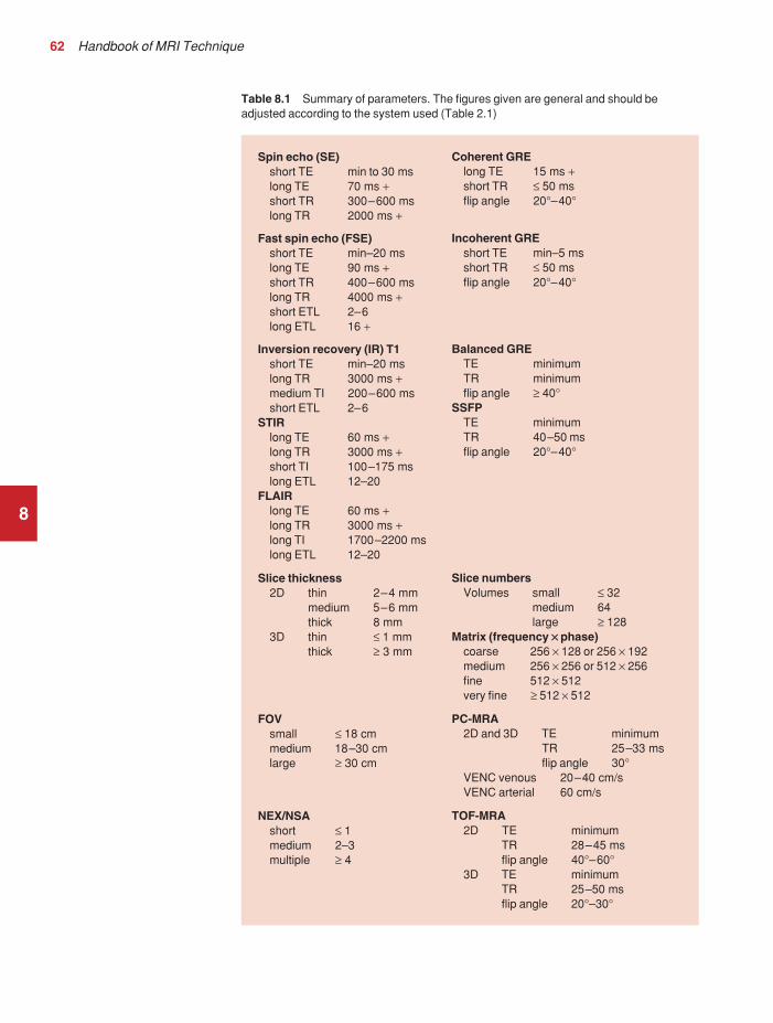
62 Handbook of MRI Technique
8
Table 8.1 Summary of parameters. The figures given are general and should beadjusted according to the system used (Table 2.1)
Spin echo (SE)short TE min to 30 mslong TE 70 ms +short TR 300–600 mslong TR 2000 ms +
Fast spin echo (FSE)short TE min–20 mslong TE 90 ms +short TR 400–600 mslong TR 4000 ms +short ETL 2–6long ETL 16 +
Inversion recovery (IR) T1short TE min–20 mslong TR 3000 ms +medium TI 200–600 msshort ETL 2–6
STIRlong TE 60 ms +long TR 3000 ms +short TI 100–175 mslong ETL 12–20
FLAIRlong TE 60 ms +long TR 3000 ms +long TI 1700–2200 mslong ETL 12–20
Slice thickness2D thin 2–4 mm
medium 5–6 mmthick 8 mm
3D thin ≤ 1 mmthick ≥ 3 mm
FOVsmall ≤ 18 cmmedium 18–30 cmlarge ≥ 30 cm
NEX/NSAshort ≤ 1medium 2–3multiple ≥ 4
Coherent GRElong TE 15 ms +short TR ≤ 50 msflip angle 20°–40°
Incoherent GREshort TE min–5 msshort TR ≤ 50 msflip angle 20°–40°
Balanced GRETE minimumTR minimumflip angle ≥ 40°
SSFPTE minimumTR 40–50 msflip angle 20°–40°
Slice numbersVolumes small ≤ 32
medium 64large ≥ 128
Matrix (frequency ×× phase)coarse 256 × 128 or 256 × 192medium 256 × 256 or 512 × 256fine 512 × 512very fine ≥ 512 × 512
PC-MRA2D and 3D TE minimum
TR 25–33 msflip angle 30°
VENC venous 20–40 cm/sVENC arterial 60 cm/s
TOF-MRA2D TE minimum
TR 28–45 msflip angle 40°–60°
3D TE minimumTR 25–50 msflip angle 20°–30°
9781405160858_4_008.qxd 28/05/2008 15:19 Page 62

Head and neck 63
Brain
Basic anatomy (Figures 8.1 and 8.2)
8Figure 8.1 Sagittal sectionthrough the brain showingmidline structures.
Figure 8.2 Transverse sectionthrough the brain showinginferior structures.
9781405160858_4_008.qxd 28/05/2008 15:20 Page 63

64 Handbook of MRI Technique
Common indications
• Multiple sclerosis (MS).• Primary tumour assessment and/or metastatic disease.• AIDS (toxoplasmosis).• Infarction (cerebral vascular accident (CVA) vs. transient ischaemic
attack (TIA)).• Haemorrhage.• Hearing loss.• Visual disturbances.• Infection.• Trauma.• Unexplained neurological symptoms or deficit.• Pre-operative planning.• Radiation treatment planning.• Follow-up (surgical or treatment).
Equipment
• Head coil (quadrature or multi-coil array).• Immobilization pads and straps.• Ear plugs.• High-performance gradients for EPI, diffusion and perfusion imaging.
Patient positioning
The patient lies supine on the examination couch with their head withinthe head coil. The head is adjusted so that the interpupillary line is parallelto the couch and the head is straight. The patient is positioned so that thelongitudinal alignment light lies in the midline, and the horizontal align-ment light passes through the nasion. Straps and foam pads are used forimmobilization.
Suggested protocol
Sagittal SE/FSE/incoherent (spoiled) GRE T1
Medium slices/gap are prescribed on each side of the longitudinal alignmentlight from one temporal lobe to the other. The area from the foramenmagnum to the top of the head is included in the image.
L 37 mm to R 37 mm
Axial/oblique SE/FSE PD/T2 (Figure 8.5)
Medium slices/gap are prescribed from the foramen magnum to the super-ior surface of the brain. Slices may be angled so that they are parallel to
8
9781405160858_4_008.qxd 28/05/2008 15:20 Page 64

Head and neck 65
the anterior–posterior commissure axis. This enables precise localizationof lesions from reference to anatomy atlases (Figures 8.3 and 8.4). Manysites have replaced the PD sequence with FLAIR (see below). SS-FSE orSS-EPI may be a necessary alternative for a rapid examination in uncoop-erative patients.
Coronal SE/FSE PD/T2
As for Axial PD/T2, except prescribe slices from the cerebellum to thefrontal lobe (Figure 8.6).
Additional sequences
Axial/oblique IR T1 (Figure 8.7)
Slice prescription as for Axial/oblique T2.This sequence is especially useful in imaging the paediatric brain (see
Paediatric imaging later in Part 2). White matter does not fully myelinateuntil approximately 5 years of age, therefore in the very young patient,grey and white matter have very similar T1 relaxation times, and the CNRbetween these tissues is small on SE T1 sequences.
8
Figure 8.3 Sagittal SE T1weighted midline slice of thebrain showing the axis of theanterior and posteriorcommissures.
9781405160858_4_008.qxd 28/05/2008 15:20 Page 65

8
Figure 8. 5 Axial/oblique FSET2 weighted image of the brainshowing normal appearances.
Figure 8.4 Sagittal SE T1weighted midline slice of thebrain showing slice prescriptionboundaries and orientation foraxial/oblique imaging.
9781405160858_4_008.qxd 28/05/2008 15:20 Page 66

8
Figure 8.6 Sagittal SE T1weighted image showing sliceprescription boundaries andorientation for coronal imaging.
Figure 8.7 Axial IR T1weighted image using a TI of700 ms.
9781405160858_4_008.qxd 28/05/2008 15:20 Page 67

68 Handbook of MRI Technique
Axial/oblique FLAIR/EPI (Figure 8.8)
Slice prescription as for Axial/oblique T2.This sequence provides a rapid acquisition with suppression of CSF sig-
nal. It may be useful when examining periventricular or cord lesions suchas MS plaques.
Axial/oblique SE/FSE/incoherent (spoiled) GRE T1 (Figure 8.9)
Slice prescription as for Axial/oblique T2.Pre- and post-contrast scans are common especially for tumour
assessment.
SS-FSE T2 (Figure 8.10)
Useful for rapid imaging in uncooperative patients.
8
Figure 8.8 Axial/obliqueFLAIR image of the brain.Periventricular abnormalities willhave a high signal intensity incontrast to the low signal of CSFwhich has been nulled using along TI.
9781405160858_4_008.qxd 28/05/2008 15:20 Page 68

8
Figure 8. 9 Axial/obliqueincoherent (spoiled) GRE imageof the brain.
Figure 8.10 SS-FSE T2weighted image of the brain.The entire brain was scanned in 40 s.
9781405160858_4_008.qxd 28/05/2008 15:20 Page 69

70 Handbook of MRI Technique
Axial 3D incoherent (spoiled) GRE T1
This sequence is useful for high-resolution imaging of small structureswithin the brain. If reformatting of slices is desired, an isotropic datasetmust be acquired (see Volume imaging under Parameters and trade-offs inPart 1).
Axial/oblique GRE/EPI T1/T2 (Figure 8.11)
Due to sensitivity to magnetic susceptibilities, these sequences demon-strate haemorrhage better than SE and FSE.
Axial/oblique SE MT
Slice prescription as for Axial/oblique T2.MT is a useful sequence to improve visualization of lesions such as
metastasis, and some low-grade tumours, as grey and white matter loses30–40% of its signal when a MT pulse sequence is utilized. The CNRbetween lesions and the surrounding brain is therefore increased (seePulse sequences in Part 1).
8 Figure 8.11 Single shot EPIimage of the brain. The entirebrain was scanned in 14 s.
9781405160858_4_008.qxd 28/05/2008 15:20 Page 70

Head and neck 71
Axial DWI (Figures 8.12 and 8.13)
Slice prescription as for Axial/oblique T2.This sequence is important in the investigation of early stroke. It is also
utilized in paediatric patients to investigate the effects of hypoxia andmyelination patterns (see Paediatric imaging later in Part 2). A b-value of800–1000 s/mm2 is selected (the higher the b-value, the more diffusionweighting). Isotropic diffusion should be acquired (i.e. diffusion gradientsapplied in all three axes) (see Pulse sequences in Part 1).
A DWI sequence is most often acquired using a T2 weighted EPIsequence. In a standard T2 weighted EPI sequence, there is not enoughmotion (diffusion) of the extra-cellular water during the imaging cycle toresult in dephasing of the water protons. Diffusion gradients are thereforeutilized to increase the sensitivity to the motion of the extra-cellular watermolecules. The b-value controls the amplitude, duration and/or timing of these diffusion gradients and thus determines the amount of diffusionweighting in a diffusion sequence. Increasing the b-value increases thesensitivity to the motion (diffusion) of extra-cellular water in tissue and thus increases the diffusion weighting. The signal in areas of normal
8
Figure 8.12 DWI showinglarge area of high signal onright. High signal on a DWI canbe the result of restricteddiffusion or ‘T2 shine-through’.
9781405160858_4_008.qxd 28/05/2008 15:20 Page 71

72 Handbook of MRI Technique
diffusion is reduced due to the dephasing of the water protons in the presence of these diffusion gradients. The more restricted the diffusion,the less dephasing of the water protons and higher signal will be seen onthe diffusion image. On most MR systems both the b = 0 image (i.e. theT2-weighted EPI image) and the diffusion image with the b value chosenby the operator will be displayed. Some systems may also display three additional images per slice location. These are the images obtained duringthe diffusion acquisition. The diffusion gradients are applied in each ofthe three orthogonal planes (X, Y and Z) measuring the diffusion in eachof those directions. The data are then averaged to produce the final ‘trace’or diffusion-weighted image displayed.
It is important to remember that high signal seen on a diffusion-weighted image may actually be high signal from spins with a long T2-relaxation time ‘shining through’. These so-called ‘T2 shine-through’effects are eliminated by the calculation and production of an ADC map or image. The apparent diffusion coefficient (ADC) expresses theamount of motion of extra-cellular water. The ADC image is calculatedfrom the b value of 0 and the b value used in the diffusion acquisition(most commonly 1000 mm/s2 in a DWI exam of the brain) to produce a
8
Figure 8.13 Calculated ADCimage showing restricteddiffusion (acute stroke) as lowsignal. Small area of high signalin right posterior represents ‘T2shine-through’.
9781405160858_4_008.qxd 28/05/2008 15:20 Page 72

Head and neck 73
‘2-point’ ADC image (Figure 8.13). In some situations, one may acquire aDWI with two b values. That, along with the b value of 0, would be usedto calculate a ‘3-point’ ADC image. In any event, the pixel values in anADC image represent the ADC of pixels in the image. In areas withrestricted diffusion (i.e. low ADC), the pixel values are dark. A high ADC,seen in the presence of mobile water protons will result in a bright pixel onthe ADC image. Calculating and producing an ADC image is very import-ant in distinguishing between acute and chronic stokes. Depending on the MR system, the ADC image may be produced automatically or it mayrequire some minor additional processing steps.
Diffusion tensor imaging (DTI)
When the diffusion of water along the three orthogonal directions of themagnet (X, Y and Z) is measured and the average obtained, only isotropicdiffusion information is acquired; that is diffusion that is random in direc-tion. In the brain this is seen in grey matter. In white matter, the structureof the tissue ‘orders’ the diffusion. In white matter diffusion is orderedalong the white matter tracts. This type of ordered diffusion is referred toas anisotropy (anisotropic diffusion). In order to image anisotropic diffu-sion, diffusion in more than three axes is measured. In physics, a tensor isbasically motion as a function of direction. DTI is essentially imaging dif-fusion that is ordered in direction (anisotropic rather than isotropic). At aminimum, DTI must measure the diffusion along at least six axes. In clin-ical practice twelve or more directions are measured. Due to a loss in SNRas the number of directions measured increases, DTI is particularly usefulat high field strengths such as 3 T. DTI is currently used for mapping white matter tracts as fractional anisotropy (FA) maps, or as tractographyimages (Figures 8.14–8.18).
Axial perfusion imaging
Slice prescription as for Axial/oblique T2.This sequence provides temporal resolution of enhancing lesions and
indicates activity. Injection of a gadolinium bolus should begin immedi-ately after the scan is initiated. Post-enhancement T1 imaging follows theperfusion series (see Pulse sequences and its subheading Dynamic imagingin Part 1).
The use of an MR compatible contrast injector greatly increases theconsistency of perfusion information. Furthermore, in order to optimizethe susceptibility effects, a rapid bolus of contrast is necessary. A min-imum injection rate of 4 ml/second is preferable. The amount or volumeinjected may vary depending on concentration of the contrast media,relaxivity of the contrast media, field strength, and/or pulse sequence utilized. At 1.5 T, the strongest effects are seen using a GRE-EPIsequence. If such a sequence is used 0.1 mmol/kg is typically adequate.Due to the increased susceptibility effects seen with a GRE-EPI sequence,only information regarding large vessel perfusion is obtained. If one
8
9781405160858_4_008.qxd 28/05/2008 15:20 Page 73

8
Figure 8.14 T2-weighedFLAIR showing lesion.
Figure 8.15 Fractionalanisotropy (FA) map showinganisotropic (ordered) diffusion in the white matter tracts.
9781405160858_4_008.qxd 28/05/2008 15:20 Page 74

8
Figure 8.16 Coronal T2-weighted EPI demonstrateslesion.
Figure 8.17 FA map showswhite matter tracts relative to the lesion.
9781405160858_4_008.qxd 28/05/2008 15:20 Page 75

76 Handbook of MRI Technique
wishes to obtain information relating to small vessel perfusion, then a SE-EPI sequence should be utilized. It is important to remember howeverthat due to the reduced susceptibility effects obtained with the SE-EPIsequence, a higher dose or concentration of gadolinium may be necessary.Not all gadolinium agents have the same effect on T1 and T2-relaxationtimes. There are some agents with higher relaxivities (r1 and r2). Theseagents, when used for perfusion imaging, result in greater signal reductionwhen compared with the same dose of a standard gadolinium agent due tothe increased r2 (relaxivity). At 3.0 T, susceptibility effects are increasedas a function of the field strength and allow for either a reduced dose ofgadolinium (0.5 mmol/kg) with a GRE-EPI sequence or a standard dose(0.1 mmol/kg) of gadolinium with a SE-EPI sequence. SE-EPI sequencesalso result in fewer susceptibility artefacts. In summary, the amount ofgadolinium used for perfusion imaging is dependent upon the type of contrast agent used, field strength and acquisition technique selected.
When perfusion imaging is utilized for stroke imaging, the area affectedby the stroke appears as either an area of late arriving contrast or totallynon-perfusing. When imaging a tumour, however, the area of abnormalperfusion will often be demonstrated as an area of hyper-perfusion. The
8 Figure 8.18 Tractographydemonstrates tract orientationrelative to the lesion.
9781405160858_4_008.qxd 28/05/2008 15:21 Page 76

Head and neck 77
images in Figures 8.19 and 8.20 illustrate this effect. The area of residualtumour is indistinguishable from the adjacent tissue due to oedema andother changes. The perfusion data clearly show an area of increased orhyper-perfusion indicating residual or recurrent tumour.
Technical Issues
Image optimization
Using a quadrature or multi-coil array will yield high and uniform signal.Using a multi-coil array with greater than four channels however mayrequire the use of a uniformity correction algorithm to produce an imagewith uniform signal throughout. Regardless of the coil selected, imageswith excellent SNR and spatial resolution should be easily attainable inreasonable scan times.
FSE is the pulse sequence most often utilized for acquiring PD and T2weighted images due to its shorter scan times compared with CSE. Thereis some debate as to whether PD and T2 weighted images should be
8Figure 8.19 T2-weightedimage shows large area ofoedema following treatment.
9781405160858_4_008.qxd 28/05/2008 15:21 Page 77

78 Handbook of MRI Technique
acquired as part of a dual echo acquisition or separately. TRs in the orderof 3500 ms or higher are usually employed in T2 weighted FSE imaging.For PD weighted images of the brain, however, such a high TR is not optimal. If the TR is increased above 2000 ms, signal intensity of CSFincreases due to reduced saturation and the high proton density of CSF.This may reduce contrast between some peri-ventricular lesions such asMS and CSF.
Blurring may be more prominent with the long ETL traditionally asso-ciated with T2 weighted FSE. A short ETL and TE are required for PD weighting to minimize T2 effects, whereas a long ETL and TE arerequired for T2 contrast. Blurring increases the longer the train of echoesgoes out in time. Due to T2 dephasing, the echoes that occur a long wayout in the train have lower signal amplitude than those at the beginning of the train. If the effective TE does not coincide with these late echoes,data from them are mapped into the resolution lines of K space and resultin blurring. The echo spacing is also important as, if the echo spacing islong the final echoes in the train will occur much later in time, and there-fore be of lower signal intensity than if the spacing is short, even in a traincontaining a relatively small number of echoes. Conversely, if the echo
8Figure 8.20 Perfusion datashows area of hyperperfusionwithin the oedema indicatingrecurrent tumour.
9781405160858_4_008.qxd 28/05/2008 15:21 Page 78

Head and neck 79
spacing is short, the final echoes are collected earlier in time and will be of higher signal intensity, even in a train containing a larger number ofechoes. (Note: The term ‘echo train length’ refers to the number of echoescollected rather than the time taken to do so). The exact method of con-trolling the echo spacing varies from vendor to vendor. Faster switchinggradients (i.e. higher slew rates) allow for a long ETL with tight echospacing. Generally speaking, the echo spacing should be kept as low aspossible to minimize blurring.
As a result of these limitations, some advocate acquiring the PD and T2 weighted images separately as this permits the use of a shorter TR and ETL in the PD acquisition. Alternatively some vendors allow the echotrain to be split in dual echo FSE acquisitions so that the PD weightedimage is acquired from the first echoes in the train and the T2 weightedimage from the later echoes in the train. This results in more optimalweighting for both images but note that in FSE, unlike CSE, the acquisi-tion time for PD images is shorter than that for T2 or dual echo. This isbecause a TR of 2000 ms is used rather than 10 000 ms. There is there-fore a time-saving to be made when only PD weighting is required. In CSEin the interests of reducing scan time, T2 weighted images already have arelatively short TR. PD and T2 weighted images therefore have similaracquisition times and are routinely acquired simultaneously in a dual echosequence. There is therefore no time-saving to be made by acquiring PDweighted images on their own.
Despite the time advantages of using FSE in the brain, the multiple 180º
pulses in an FSE sequence reduce the sensitivity to haemorrhagic lesions.If haemorrhagic lesions are suspected, a coherent gradient echo sequencemay be acquired in addition to the regular sequences. It should also benoted that in many institutions, T2-FLAIR images have replaced PD-weighted images in the brain.
Due to the relatively high SNR, only a few NEX/NSA are usuallyrequired to achieve adequate image quality. However, this may not be thecase when examining small structures with thin slices and/or a smallerFOV. In such a situation, it may be necessary to increase the NEX/NSA.The receive bandwidth may be decreased to increase the SNR withoutsignificantly increasing chemical shift artefact. However, generally speak-ing, as the receive bandwidth is reduced, the echo spacing increases andcould result in an increase in FSE blurring. Rectangular FOV or parallelimaging may be utilized to reduce scan times in axial and/or coronal imag-ing with the phase encoding direction being R to L.
Artefact problems
The main source of artefact in the brain is from flow motion of the carotidand vertebral arteries. A spatial presaturation pulse placed I to the FOVreduces this significantly. In large FOV imaging, there is no need to placespatial presaturation pulses anywhere other than I, as there is no flowcoming into the FOV from any other direction. If a small FOV is used, Sor R and L spatial presaturation pulses are sometimes necessary.
8
9781405160858_4_008.qxd 28/05/2008 15:21 Page 79
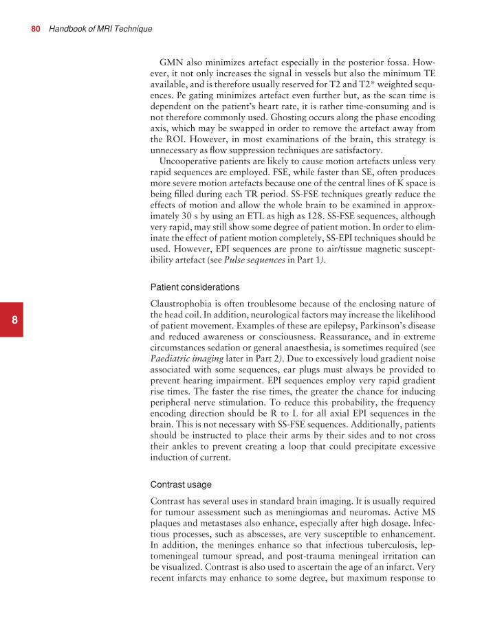
80 Handbook of MRI Technique
GMN also minimizes artefact especially in the posterior fossa. How-ever, it not only increases the signal in vessels but also the minimum TEavailable, and is therefore usually reserved for T2 and T2* weighted sequ-ences. Pe gating minimizes artefact even further but, as the scan time isdependent on the patient’s heart rate, it is rather time-consuming and isnot therefore commonly used. Ghosting occurs along the phase encodingaxis, which may be swapped in order to remove the artefact away fromthe ROI. However, in most examinations of the brain, this strategy isunnecessary as flow suppression techniques are satisfactory.
Uncooperative patients are likely to cause motion artefacts unless veryrapid sequences are employed. FSE, while faster than SE, often producesmore severe motion artefacts because one of the central lines of K space isbeing filled during each TR period. SS-FSE techniques greatly reduce theeffects of motion and allow the whole brain to be examined in approx-imately 30 s by using an ETL as high as 128. SS-FSE sequences, althoughvery rapid, may still show some degree of patient motion. In order to elim-inate the effect of patient motion completely, SS-EPI techniques should beused. However, EPI sequences are prone to air/tissue magnetic suscept-ibility artefact (see Pulse sequences in Part 1).
Patient considerations
Claustrophobia is often troublesome because of the enclosing nature ofthe head coil. In addition, neurological factors may increase the likelihoodof patient movement. Examples of these are epilepsy, Parkinson’s diseaseand reduced awareness or consciousness. Reassurance, and in extremecircumstances sedation or general anaesthesia, is sometimes required (seePaediatric imaging later in Part 2). Due to excessively loud gradient noiseassociated with some sequences, ear plugs must always be provided toprevent hearing impairment. EPI sequences employ very rapid gradientrise times. The faster the rise times, the greater the chance for inducingperipheral nerve stimulation. To reduce this probability, the frequencyencoding direction should be R to L for all axial EPI sequences in thebrain. This is not necessary with SS-FSE sequences. Additionally, patientsshould be instructed to place their arms by their sides and to not crosstheir ankles to prevent creating a loop that could precipitate excessiveinduction of current.
Contrast usage
Contrast has several uses in standard brain imaging. It is usually requiredfor tumour assessment such as meningiomas and neuromas. Active MSplaques and metastases also enhance, especially after high dosage. Infec-tious processes, such as abscesses, are very susceptible to enhancement. In addition, the meninges enhance so that infectious tuberculosis, lep-tomeningeal tumour spread, and post-trauma meningeal irritation can be visualized. Contrast is also used to ascertain the age of an infarct. Veryrecent infarcts may enhance to some degree, but maximum response to
8
9781405160858_4_008.qxd 28/05/2008 15:21 Page 80

Head and neck 81
contrast usually occurs after the blood–brain barrier has been breached.Old or chronic infarcts do not enhance. Either SE or incoherent (spoiled)GRE T1 are the sequences of choice after contrast. If a 3D incoherent(spoiled) GRE sequence is acquired using isotropic voxels, the datasetmay be reformatted in other planes and/or slice locations. Perfusion imag-ing, with a rapidly infused bolus of gadolinium, is useful for measuringthe activity of a lesion. In these cases rapid acquisitions such as SS-FSE orEPI are required.
8
9781405160858_4_008.qxd 28/05/2008 15:21 Page 81

82 Handbook of MRI Technique
Temporal lobes
Basic anatomy (Figure 8.21)
8 Figure 8.21 The temporal lobeand its relationships.
Common indications
• Diagnosis and evaluation of a lesion specifically in the temporallobes (tumours, vascular malformations, leukodystrophies andatrophic processes).
• Temporal lobe epilepsy.• Evaluation of signal change in the hippocampus and the temporal lobe• Measurement of the hippocampal volume (hippocampal atrophy is
presently considered the most sensitive indicator of hippocampaldisease especially in Alzheimer’s disease and schizophrenia).
Equipment
• Head coil (quadrature, or multi-coil array).• Immobilization pads and straps.• Ear plugs.
Patient positioning
The patient lies supine on the examination couch with their head withinthe head coil. The head is adjusted so that the interpupillary line is parallel
9781405160858_4_008.qxd 28/05/2008 15:21 Page 82

Head and neck 83
to the couch and the head is straight. The patient is positioned so that thelongitudinal alignment light lies in the midline, and the horizontal align-ment light passes through the nasion. Straps and foam pads are used forimmobilization.
Suggested protocol
Sagittal SE T1
Medium slices/gap are prescribed on either side of the longitudinal align-ment light through the whole head. The area from the foramen magnumto the top of the head is included in the image.
L 37 mm to R 37 mm
Axial/oblique SE/FSE T2
Thin slices/gap or interleaved are angled parallel to the temporal lobe thatcan be seen on a lateral slice on the sagittal images (Figure 8.22). Prescribethe slices from the inferior aspect of the temporal lobes to the superiorborder of the body of the corpus callosum.
8
Figure 8.22 Sagittal SE T1weighted image through atemporal lobe showing sliceprescriptions boundaries andorientation for axial/obliqueimaging of the temporal lobes.
9781405160858_4_008.qxd 28/05/2008 15:21 Page 83

84 Handbook of MRI Technique
Coronal/oblique SE/FSE T1
As for the Axial/oblique T2, except thin slices interleaved are angled perpendicular to the axials (Figure 8.23).
Slices are prescribed from the posterior portion of the cerebellum to theanterior border of the genu of the corpus callosum.
Coronal 3D incoherent (spoiled) GRE T1 (Figure 8.24)
Thin slices are either prescribed through the temporal lobes only (mediumnumber of slice locations), or the whole head (large number of slice loca-tions). For hippocampal measurements, slices are prescribed from theposterior portion of the cerebellum to the anterior border of the genu ofthe corpus callosum. Hippocampal volumes are measured by using sys-tem software to calculate the area of the hippocampus on each slice andmultiplying this by the depth of the slice slab. If reformatting of slices isdesired, then an isotropic dataset should be acquired (see Volume imagingunder Parameters and trade-offs in Part 1).
8
Figure 8.23 Sagittal SE T1weighted image through atemporal lobe showing sliceprescription boundaries andorientation for coronal/obliqueimaging of the temporal lobes.
9781405160858_4_008.qxd 28/05/2008 15:21 Page 84

Head and neck 85
Axial/oblique/Coronal/oblique IR-FSE T2 (Figures 8.25 and 8.26)
Slice prescription as for Axial/oblique/Coronal/oblique FSE T2.This sequence often provides images with high contrast between grey
matter and white matter. A TI selected to null the signal from white mat-ter (about 300 ms) can be used to increase the grey/white contrast in thehippocampal region. Images may be video-inverted so that white matterappears white and the grey matter appears grey. This is sometimes usefulto increase the conspicuity of white matter lesions, which have a low signal intensity when using this technique.
Image optimization
Technical issues
The SNR and contrast characteristics of the temporal lobes are usuallyexcellent as the quadrature head coil and phased array coil yield high and uniform signal. Good spatial resolution is therefore achievable in
8
Figure 8.24 Coronalincoherent (spoiled) T1weighted GRE image throughthe hippocampi acquired as partof a 3D acquisition.
9781405160858_4_008.qxd 28/05/2008 15:21 Page 85

8
Figure 8.25 Axial IR-FSE T2 weighted image with a TIselected to null the signal fromwhite matter (300 ms).
Figure 8.26 Axial IR-FSE T2weighted image video invertedto better demonstrate whitematter lesions.
9781405160858_4_008.qxd 28/05/2008 15:21 Page 86

Head and neck 87
relatively short scan times. Surface coils placed directly on the patient’shead increase local SNR and resolution, especially in children. However,using this method, other areas of the brain cannot be imaged due to signalfall-off. As lesions within the temporal lobes are often quite small, volumeacquisitions are useful as they allow for very thin slices and no gap. Asthey are mainly utilized to demonstrate anatomy or contrast enhance-ment, an incoherent (spoiled) GRE that produces PD and T1 contrast isdesirable. Alternatively, angling the slices perpendicular to the sylvianfissure in 2D acquisitions often improves visualization of the temporallobes.
FSE is a useful pulse sequence especially for T2 weighted images, as FSE in conjunction with fine matrices acquires high-resolution images of the temporal lobes in a relatively short scan time. However, IRsequences can also be utilized to great effect. FLAIR sequences usuallydemonstrate subtle areas of increased T2 signal intensity better than T2 weighted SE or FSE sequences. As the brain contains no fat (only small amounts occur in the scalp), reducing the receive bandwidth sig-nificantly improves the SNR without significantly increasing chemicalshift artefact, although there may be increased blurring (see Flow phe-nomena and artefacts in Part 1). A rectangular/asymmetric FOV can beeffectively used to reduce scan times in axial and coronal imaging with thephase axis R to L.
Artefact problems
The main source of artefact in the temporal lobes is from flow motion ofthe carotid and vertebral arteries. A spatial presaturation pulse placed I to the FOV reduces this significantly. In large FOV imaging, there is noneed to place spatial presaturation pulses anywhere other than I, as thereis no flow coming into the FOV from any other direction. On coronalimages, phase artefact from the carotid and vertebral vessels is often trou-blesome. Swapping the phase axis so that it lies S to I instead of R to Lremoves artefact away from the laterally situated temporal lobes, butoversampling is necessary to prevent the neck and the top of the headwrapping into the FOV along the phase axis. This method of swappingthe phase direction is used most effectively to reduce artefact in the lateralportion of the temporal lobes. However, phase ghosting can still interferewith the more medially situated hippocampi, and if they are the ROI thereis probably no benefit in swapping the phase axis.
GMN also minimizes artefact in the temporal lobes. However, it notonly increases the signal in vessels but also the minimum TE available,and is therefore usually reserved for T2 and T2* weighted sequences.Magnetic susceptibility is often seen at high field strengths on the coronalincoherent (spoiled) GRE images, especially at the border of the petrousridge and the brain. If slices are prescribed through the temporal lobeonly, spatial presaturation pulses are brought into the FOV in the volumeacquisition to reduce aliasing along the slice select axis (see Volume imag-ing under Parameters and trade-offs in Part 1).
8
9781405160858_4_008.qxd 28/05/2008 15:21 Page 87

88 Handbook of MRI Technique
Patient considerations
Claustrophobia is often troublesome because of the enclosing nature ofthe head coil. Careful explanation of the procedure and reassurance isnecessary. As many of these patients have drug-resistant epilepsy, carefulobservation of the patient throughout the examination is important. Thegradient noise and bore and alignment lights are potential sources ofepileptic stimuli. If the patient fits during the examination stop scanningimmediately, withdraw the patient from the magnet, call a physician andinstigate first-aid measures. Owing to excessively loud gradient noiseassociated with some sequences, ear plugs must always be provided toprevent hearing impairment.
Contrast usage
Contrast is sometimes helpful to demonstrate small lesions in the temporallobes.
8
9781405160858_4_008.qxd 28/05/2008 15:21 Page 88

Head and neck 89
Posterior fossa and internal auditory meati
Basic anatomy (Figure 8.27)
8
Figure 8.27 The anatomy ofthe inner ear.
Common indications
• Symptoms that require the exclusion of an acoustic neuroma (vertigo, unilateral sensory hearing loss, tinnitis).
• Facial palsy/numbness.• Diagnosis of a posterior fossa lesion.• Hemifacial spasm.• Trigeminal neuralgia.
Equipment
• Head coil (quadrature or multi-coil array).• Immobilization pads and straps.• Ear plugs.
Patient positioning
The patient lies supine on the examination couch with their head withinthe head coil. The head is adjusted so that the interpupillary line is parallelto the couch and the head is straight. The patient is positioned so that thelongitudinal alignment light lies in the midline, and the horizontal align-ment light passes through the nasion. Straps and foam pads are used forimmobilization.
9781405160858_4_008.qxd 28/05/2008 15:21 Page 89

90 Handbook of MRI Technique
Suggested protocol
Sagittal SE T1 or coherent GRE T2* (Figure 8.28)
Medium slices/gap are prescribed either on each side of the longitudinalalignment light, or through the internal auditory meatus (IAM) on oneside only. The area from the foramen magnum to the superior border ofthe body of the corpus callosum is included in the image.
L 37 mm to L 20 mm (left IAM)R 37 mm to R 20 mm (right IAM)
Axial SE/FSE T1 (Figure 8.29)
Thin slices/gap or interleaved are prescribed through the posterior fossafrom the foramen magnum to the superior border of the petrous ridge.Coverage is increased if a large posterior fossa tumour is present.
Axial SE/FSE T1 with contrast
Slice prescription as for Axial T1.
8
Figure 8.28 Sagittal SE T1weighted midline slice throughthe brain showing sliceprescription boundaries andorientation for axial imaging ofthe internal auditory meatus(IAM).
9781405160858_4_008.qxd 28/05/2008 15:21 Page 90
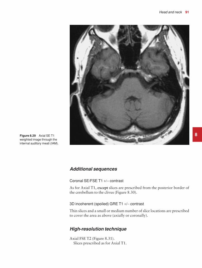
Head and neck 91
Additional sequences
Coronal SE/FSE T1 +/− contrast
As for Axial T1, except slices are prescribed from the posterior border ofthe cerebellum to the clivus (Figure 8.30).
3D incoherent (spoiled) GRE T1 +/− contrast
Thin slices and a small or medium number of slice locations are prescribedto cover the area as above (axially or coronally).
High-resolution technique
Axial FSE T2 (Figure 8.31).Slices prescribed as for Axial T1.
8Figure 8.29 Axial SE T1weighted image through theinternal auditory meati (IAM).
9781405160858_4_008.qxd 28/05/2008 15:21 Page 91

92 Handbook of MRI Technique
Thin slices/gap or interleaved 3 mmLong TE 100 msLong TR 4000 msLong ETL 16Matrix 512 × 256 or greaterNEX/NSA 4FOV 20 cm
Coronal
As for Axial high resolution T2, except prescribe slices from the posteriorborder of the cerebellum to the clivus.
3D FSE T2 or GRE T2* (Figure 8.32)
This sequence produces images with high contrast and SNR. Addition-ally, the images are contiguous and will not suffer from cross-excitation.An isotropic acquisition allows multiplanar reformatting (see Volumeimaging under Parameters and trade-offs in Part 1). GRE sequences such
8
Figure 8.30 Sagittal SE T1weighted midline slice throughthe brain showing sliceprescription boundaries andorientation for coronal imagingof the internal auditory meati(IAM).
9781405160858_4_008.qxd 28/05/2008 15:21 Page 92

Head and neck 93
as balanced gradient echo are commonly used as flow artefacts from theposterior fossa are reduced.
Image optimization
Technical issues
The IAM are very small structures and this examination is usually carried out to exclude a small acoustic neuroma situated within the canal.Therefore it is important to achieve the highest spatial resolution possiblein keeping with good SNR. The inherent SNR is usually excellent due tothe high proton density of the brain tissue and the quality of the head coil.However, in the region of the IAM, the low proton density of the petrousbones and mastoids reduces the SNR. The thinnest slices and smallest gapor interleaving are used to optimize spatial resolution and visualization of the IAM. A very fine matrix is advisable, although increasing this toomuch can reduce the SNR to unacceptable levels. To optimize spatial
8Figure 8.31 Axial FSE T2weighted high resolution imageof the internal auditory meati(IAM).
9781405160858_4_008.qxd 28/05/2008 15:21 Page 93

94 Handbook of MRI Technique
resolution even further, the FOV is reduced compared with standardbrain imaging. As a result of all these measures, the NEX/NSA may haveto be increased to maintain SNR.
A high-resolution T2 FSE technique usually negates the use of contrastenhancement and the T1 sequence, especially when examining the IAM.When FSE is used in conjunction with matrices of at least 512, extremelygood resolution and contrast are achievable. The T2 weighting of thesequence produces excellent contrast between the high signal of the CSFand the relatively low signal of the nerve. The fine matrix gives very goodresolution of many of the cranial nerves and vessels in the posterior fossa.The facial and auditory nerves can usually be seen as distinct from eachother within the canal, and under these circumstances contrast may not benecessary. The NEX/NSA is increased to maintain the SNR, but the scantimes are still only in the order of a few minutes due to the implementationof FSE. However, at lower field strengths more NEX/NSA are usuallyrequired to achieve satisfactory SNR. This sequence is also useful in thecoronal plane when looking specifically at the posterior fossa.
Volume acquisitions eliminate the slice gap and enable very thin slices to be acquired. Incoherent (spoiled) GRE sequences after contrast
8
Figure 8.32 Axial FSE T2weighted high resolution imageof the internal auditory meati(IAM) demonstrating a large left acoustic neuroma. Thisexamination did not requirecontrast to confirm thediagnosis.
9781405160858_4_008.qxd 28/05/2008 15:21 Page 94

Head and neck 95
enhancement are common, but heavily T2 weighted acquisitions usingFSE or GRE are often superior. Magnetization prepared sequences mayalso be of value. If the whole of the posterior fossa is under examination,spatial resolution may not be as important as with the IAM. If the ROI islarge (such as a tumour invading the fossa) slightly thicker slices/gap areemployed, and a routine brain protocol is often required.
Artefact problems
Flow motion from the venous sinuses is often troublesome in the posteriorfossa. GMN minimizes this artefact but it not only increases the signal in vessels but also the minimum TE available, and is therefore reserved for T2 weighted sequences. Spatial presaturation pulses placed S and I tothe FOV are also beneficial. Pe gating reduces artefact even further but, as the scan time is dependent on the patient’s heart rate, it is sometimesrather time-consuming. The implementation of Pe gating is, therefore,best reserved for cases of severe flow artefact that cannot be reduced totolerable levels by other measures. The use of balanced gradient echo alsoreduces flow artefact due to use of the balanced gradient system and shortTE and TR (see Pulse sequences in Part 1).
Patient considerations
Claustrophobia is sometimes troublesome because of the enclosing natureof the head coil, and patients are often very deaf and may not respond tothe system intercom. Under these circumstances, careful explanation andreassurance of the patient are important. Due to excessively loud gradientnoise associated with some sequences, ear plugs must always be providedto prevent hearing impairment.
Contrast usage
As T1 weighted sequences yield low inherent contrast between thepetrous ridge and the IAM and acoustic neuromas demonstrate goodenhancement, contrast is usually necessary. However, the high-resolutiontechnique and/or the 3D FSE sequence often diagnoses or rules out anacoustic neuroma without contrast.
8
9781405160858_4_008.qxd 28/05/2008 15:21 Page 95

96 Handbook of MRI Technique
Pituitary fossa
Basic anatomy (Figure 8.33)
8
Common indications
• Investigation of diseases related to pituitary function (hyperprolac-tinaemia, Cushing’s disease, acromegaly, hypopituitarism, diabetesinsipidus, amenorrhoea).
• Hypothalamic disorders.• Visual field defect.• Post-operative assessment of pituitary adenomas.
Equipment
• Head coil (quadrature or multi-coil array).• Immobilization pads and straps.• Ear plugs.
Patient positioning
The patient lies supine on the examination couch with their head withinthe head coil. The head is adjusted so that the interpupillary line is parallel
Figure 8.33 The componentsof the pituitary gland.
9781405160858_4_008.qxd 28/05/2008 15:22 Page 96

Head and neck 97
to the couch and the head is straight. The patient is positioned so that thelongitudinal alignment light lies in the midline, and the horizontal align-ment light passes through the nasion. Straps and foam pads are used forimmobilization.
Suggested protocol
Sagittal SE T1 (Figure 8.34)
Thin slices/gap or interleaved are prescribed from the left to the right lateral borders of the pituitary fossa. The area from the inferior edge ofthe sphenoid sinus to the superior portion of the lateral ventricles isincluded in the image.
L 10 mm to R 10 mm
Coronal SE/FSE T1 (Figure 8.35)
Thin slices/gap or interleaved are prescribed from the posterior clinoids tothe anterior clinoids. The inferior border of the sphenoid sinus to the
8
Figure 8.34 Sagittal SE T1weighted midline slice throughthe brain showing sliceprescription boundaries andorientation for coronal imagingof the pituitary fossa.
9781405160858_4_008.qxd 28/05/2008 15:22 Page 97
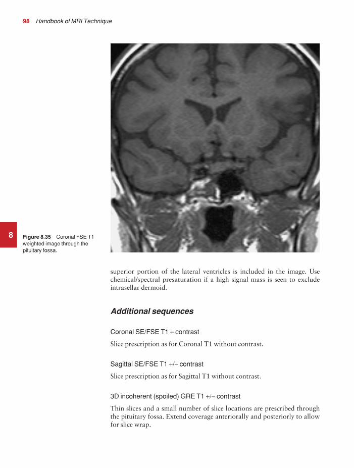
98 Handbook of MRI Technique
superior portion of the lateral ventricles is included in the image. Usechemical/spectral presaturation if a high signal mass is seen to excludeintrasellar dermoid.
Additional sequences
Coronal SE/FSE T1 + contrast
Slice prescription as for Coronal T1 without contrast.
Sagittal SE/FSE T1 +/− contrast
Slice prescription as for Sagittal T1 without contrast.
3D incoherent (spoiled) GRE T1 +/− contrast
Thin slices and a small number of slice locations are prescribed throughthe pituitary fossa. Extend coverage anteriorally and posteriorly to allowfor slice wrap.
8 Figure 8.35 Coronal FSE T1weighted image through thepituitary fossa.
9781405160858_4_008.qxd 28/05/2008 15:22 Page 98

Head and neck 99
Axial SE/FSE T1 +/− contrast
As for Coronal T1, except slices prescribed from the floor of the pituitaryfossa to the circle of Willis (Figure 8.36).
Image optimization
Technical issues
The pituitary fossa is a relatively small structure and, in addition, micro-adenomas are often difficult to visualize. As a result spatial resolution is important. To optimize this use thin slices interleaved and the smallestFOV possible in keeping with good SNR. In addition, a fine matrix used in conjunction with multiple NEX/NSA is necessary to maintainSNR. Volume acquisitions allow for thinner slices and no gap and aretherefore sometimes useful in this area. As anatomical detail and contrastenhancement are important, an incoherent (spoiled) GRE sequence isrequired.
8
Figure 8.36 Sagittal SE T1weighted midline slice throughthe brain showing sliceprescription boundaries andorientation for axial imaging ofthe pituitary fossa.
9781405160858_4_008.qxd 28/05/2008 15:22 Page 99

100 Handbook of MRI Technique
Artefact problems
The pituitary fossa is located just anterior and inferior to the circle ofWillis and therefore flow artefact is often more troublesome than in stand-ard brain imaging. In addition, the smaller FOV increases the likelihoodof aliasing, so oversampling is necessary if anatomy exists outside theFOV in the phase direction. Spatial presaturation bands are placed S, I,and L and R of the FOV to reduce artefact and aliasing, but this oftenincreases the SAR so that the slice number available per TR decreases. Inextreme circumstances Pe gating may be required but, as the scan timedepends on the proficiency of gating and the patient’s heart rate, scantimes are often considerably lengthened.
In volume acquisitions only a small slice slab is required and, therefore,slice wrap is usually troublesome. When prescribing slices always increasecoverage to compensate for this. Spatial presaturation bands placed A andP to the edges of the slice slab help to reduce aliasing of this type (see Flowphenomena and artefacts in Part 1). GMN minimizes flow artefact in thepituitary region; however, it not only increases the signal in vessels but also the minimum TE available, and is therefore not usually beneficial in T1 weighed sequences. Incoherent (spoiled) GRE sequences throughthe pituitary fossa may suffer from excessive magnetic susceptibility arte-facts when acquired on high field systems (1.0 T and above). Lower fieldstrengths, however, can benefit from the increased SNR provided by 3Dacquisitions while taking advantage of reduced magnetic susceptibilityartefacts.
Patient considerations
Claustrophobia is often troublesome due to the enclosing nature of the head coil. Careful explanation of the procedure and reassurance arerequired to avoid the necessity of sedation. Due to excessively loud gradient noise associated with some sequences, ear plugs must always beprovided to prevent hearing impairment.
Contrast usage
Contrast is not routinely required except for diabetes insipidus andhypothalamic disorders. Contrast is sometimes necessary for Cushing’sdisease because micro-adenomas are often very small, and not seen onunenhanced scans. However, it should be noted that eventually all thepituitary gland enhances as well as the microadenoma itself, and thereforecareful timing of post-contrast scans is important. It is common to see ahigh signal intensity in the posterior lobe of the pituitary on unenhancedimages, especially in patients with diabetes. At present, the causes andclinical significance of this have not been fully evaluated. In addition,studies have shown that half-dose gadolinium may be optimal for imagingthe pituitary.
8
9781405160858_4_008.qxd 28/05/2008 15:22 Page 100

Head and neck 101
Orbits
Basic anatomy (Figure 8.37)
8
Figure 8.37 The structures ofthe orbit in sagittal section.
Common indications
• Proptosis.• Visual disturbance.• Evaluation of orbital or ocular mass lesions.
Equipment
• Small surface coil for globe and orbit.• Quadrature head coil or multi-coil array coil for orbital apex,
chiasm and intracranial optic pathways.• Immobilization straps and foam pads.• Ear plugs.
Patient positioning
The patient lies supine on the examination couch. Both orbits are usuallyexamined at the same time. If surface coils are used, these are placed overeach orbit but should not touch the patient. Special holders are often pro-vided by the manufacturers to enable the coils to be placed anteriorally
9781405160858_4_008.qxd 28/05/2008 15:22 Page 101

102 Handbook of MRI Technique
over the eyes. Ensure that the receiving side of the coils faces the orbits, i.e.towards the table. The patient assumes a fixed gaze, straight ahead, withthe eyes open. This enables the patient to focus and keeps the eyes still,thereby reducing motion artefact. Any eye make-up is removed prior tothe examination as this causes image artefact and patient discomfort,especially if it contains metal.
The patient is positioned so that the longitudinal alignment light lies inthe midline, and the horizontal alignment light passes through the orbits.If surface coils are used, this corresponds to the centre of the coils. Strapsand foam pads are used for immobilization.
Suggested protocol
Sagittal SE/FSE T1
Medium slices/gap are prescribed on either side of the longitudinal align-ment light through the whole head. The area from the foramen magnumto the top of the head is included in the image.
L 37 mm to R 37 mm
Axial/oblique SE/FSE T1 or T2 (Figure 8.40)
Thin slices/gap or interleaved are prescribed either in the true axial plane,or angled to the optic nerve from the inferior margin of the orbit to abovethe chiasm (Figures 8.38 and 8.39).
Coronal SE/FSE T2 or STIR
As for Axial/oblique T1, except prescribe slices from the posterior borderof the globe to the posterior aspect of the chiasm. Use chemical/spectralpresaturation on SE/FSE sequences (Figure 8.41).
Additional sequences
Coronal/Axial SE/FSE T1
As for Axial/Coronal above, except use contrast and chemical/spectralpresaturation.
If optic neuritis is suspected, scan the whole brain.
Image optimization
Technical issues
If surface coils are used, the SNR in the region of the globe and the anter-ior aspect of the orbit is high. This allows for excellent spatial resolution
8
9781405160858_4_008.qxd 28/05/2008 15:22 Page 102

8
Figure 8.38 Sagittal SE T1weighted image of the orbit andoptic nerve showing the correctorientation of axial/obliqueslices parallel to the optic nerve.
Figure 8.39 Sagittal SE T1weighted slice through the orbitshowing slice prescriptionboundaries and orientation foraxial/oblique imaging of theorbits and optic nerve.
9781405160858_4_008.qxd 28/05/2008 15:22 Page 103

8
Figure 8.40 Axial/oblique FSE T2 of the orbits clearlydemonstrating the lens of theeye, the globe, the optic nervesand the chiasm.
Figure 8.41 Sagittal SE T1weighted slice through the orbitsshowing slice prescriptionboundaries and orientation forcoronal imaging of the orbitsand optic nerve.
9781405160858_4_008.qxd 28/05/2008 15:22 Page 104

Head and neck 105
of small structures such as the optic nerve, but there is signal fall-off at theorbital apex. Therefore the choice of coil largely depends on the coveragerequired. If the globe, the retro-orbital area and the portion of the opticnerve within the orbit are of interest, a surface coil is the best choice. If,however, information about the chiasm and intracranial optic pathwaysis required, the head coil is necessary. Thin interleaved slices or a verysmall gap are needed to obtain the resolution within the orbit and chiasm.Fine matrices and a small FOV are also required to maintain resolution,and therefore multiple NEX/NSA are necessary to preserve SNR.
FSE is probably the ideal sequence, especially for T2 weighted images,as speed is important due to motion artefact from blinking and eye move-ment. Due to the high fat content within the orbit, chemical/spectral presaturation/STIR are often necessary to visualize orbital structures ade-quately. This is especially true on the FSE T2 sequences, where fat returnsa signal similar to the CSF surrounding the optic nerve.
Artefact problems
The main source of artefact is from eye movement. Instruct the patient to focus on the roof of the bore of the magnet and to blink as little as possible. Use the fastest sequence possible in keeping with good contrast,resolution and SNR. FSE is a valuable pulse sequence in achieving this.Flow motion in the Circle of Willis is often troublesome in the chiasm,which lies just beneath it. Use spatial presaturation bands placed S and Pto the FOV to reduce this. In addition, spatial presaturation bands placedI to the FOV reduce flow motion from the carotids. GMN also minimizesflow motion but, as it increases the signal in vessels and the minimum TE,it is usually reserved for the T2 weighted sequences.
As a small FOV is commonly used in this area, aliasing is a problemespecially if the head coil is employed, because tissue outside the FOV inthe phase axis produces signal. Oversampling is therefore required toeliminate this. If any magnetic susceptibility artefact is seen, especiallysuperiorly to the orbit, this may be due to eye make-up left on the eyelid.This must be totally removed prior to the examination. Chemical shiftartefact can occur on high field strength systems due to the presence of intra-orbital fat. Fat suppression techniques reduce this and if they are used, the receive bandwidth can be reduced to increase the SNR.Additional shimming may be required before chemical/spectral presatura-tion sequences.
Patient considerations
Some patients may be blind or partially sighted and consideration shouldbe given to this. The patient is carefully instructed on the importance ofkeeping the eyes still. Focusing is practised before the examination andthe patient told when, during the examination, blinking is undesirableand when it is allowed. Obviously if the patient is blind, focusing is notpossible and so the technique is adapted to ensure that the sequences are
8
9781405160858_4_008.qxd 28/05/2008 15:22 Page 105

106 Handbook of MRI Technique
as fast as possible. All eye make-up must be removed prior to the exam-ination to avoid artefact and to reduce discomfort, as some make-up canheat up during the examination. Due to excessively loud gradient noiseassociated with some sequences, ear plugs must always be provided toprevent hearing impairment.
Contrast usage
Contrast is valuable in assessing the optic nerve and chiasm as well asintra-orbital masses. However, due to the presence of orbital fat, theadministration of contrast only serves to increase the signal of these structures so that they are isointense with fat on T1 weighted images.Therefore some means of suppressing the fat signal is required when usingcontrast enhancement. It is important to note that STIR cannot be usedfor this purpose, as contrast decreases the T1 recovery time of the tissue sothat it is similar to that of fat. Therefore, the inverting pulse used in STIRsequences sometimes nullifies the signal from enhancing tissues as well asfat. If fat suppression is required use chemical/spectral presaturation.
8
9781405160858_4_008.qxd 28/05/2008 15:22 Page 106

Head and neck 107
Paranasal sinuses
Basic anatomy (Figure 8.42)
8
Figure 8.42 Anterior view ofthe paranasal sinuses.
Common indications
• Staging of neoplasms prior to resection.• Distinction of inflammation from neoplasm.
Equipment
• Head coil (quadrature or multi-coil array).• Immobilization foam pads and straps.• Ear plugs.
Patient positioning
The patient lies supine on the examination couch with their head within the head coil. The head is adjusted so that the interpupillary line isparallel to the couch and the head is straight. The patient is positioned sothat the longitudinal alignment light lies in the midline, and the horizontalalignment light passes through the nasion. Straps and foam pads are usedfor immobilization.
9781405160858_4_008.qxd 28/05/2008 15:22 Page 107

108 Handbook of MRI Technique
Suggested protocol
Sagittal SE T1
Medium slices/gap are prescribed on either side of the longitudinal align-ment light through the whole head. The area from the foramen magnumto the top of the head is included in the image.
L 37 mm to R 37 mm
Coronal SE/FSE T1
Medium slices/gap are prescribed from the posterior portion of the sphenoid sinus to the tip of the nose. All of the paranasal sinuses areincluded in the image from the inferior margin of the maxillary sinuses tothe superior border of the frontal sinuses (Figure 8.43).
Axial SE/FSE T1
As for Coronal T1, except prescribe slices from the inferior border of themaxillary sinuses to the superior edge of the frontal sinuses (Figure 8.44).
8
Figure 8.43 Sagittal SE T1weighted midline slice throughthe brain showing sliceprescription boundaries andorientation for coronal imagingof the paranasal sinuses.
9781405160858_4_008.qxd 28/05/2008 15:22 Page 108

Head and neck 109
Coronal/Axial SE/FSE PD/T2
Slice prescription as for Axial and Coronal T1.
Additional sequences
The use of MR to image the sinuses has recently extended into inter-ventional procedures. The use of open magnet systems that allow nearreal-time imaging has proved beneficial in functional endoscopic sinussurgery. The multiplanar capabilities of MR enable rapid visualization ofthe optic nerve in three planes so that this type of surgery has become saferand quicker.
Image optimization
Technical issues
The SNR and CNR of the sinuses are often poor due to the low protondensity of the air-filled cavities. MRI does not demonstrate bony resolution
8
Figure 8.44 Sagittal SE T1weighted midline slice throughthe brain showing sliceprescription boundaries andorientation for axial imaging ofthe paranasal sinuses.
9781405160858_4_008.qxd 28/05/2008 15:22 Page 109

110 Handbook of MRI Technique
as well as computer tomography (CT), but it is useful for visualizing thenature and extent of soft tissue masses. Spatial resolution is not usually as important as good SNR in this region. Medium slices are selected to maintain SNR, and multiple NEX/NSA are employed as long as the scantime is kept within reasonable limits. The use of FSE enables the imple-mentation of fine matrices and multiple NEX/NSA whilst maintaining relatively short scan times.
Artefact problems
The main source of artefact is from the carotid, vertebral and jugular vessels. The use of spatial presaturation pulses placed I to the FOV usuallyreduces this to acceptable levels. GMN may be employed but, as itincreases the signal in vessels and the minimum TE, it is not usuallybeneficial in T1 weighted sequences. On the axial and coronal images,phase artefact occurs in the R to L direction, which may obscure the maxillary sinuses. However, the strategy of swapping the phase directionplaces this artefact S and I, which can then interfere with the frontal, ethmoid and sphenoid sinuses. Under these circumstances, swapping the phase axis rarely has merits unless the maxillary sinuses are underexamination and flow artefact is a particular problem. If the phase axis is swapped on the coronal images, oversampling is necessary to preventwrap from the neck and top of the head. Magnetic susceptibility artefactfrom dental fillings sometimes interferes with the maxillary sinuses but is not easily remedied, other than to avoid GRE sequences.
Patient considerations
Claustrophobia is often troublesome because of the enclosing nature ofthe head coil. Under these circumstances reassurance and a careful expla-nation of the procedure is required. Some patients may have profuse nasal secretions so that they need to swallow or blow their nose frequentlyduring the examination.
Due to excessively loud gradient noise associated with some sequences,ear plugs must always be provided to prevent hearing impairment.
Contrast usage
Contrast enhances the mucous lining of the sinuses but it is not com-monly used for sinus disease. It is, however, useful to distinguish betweenenhancing tumour and non-enhancing effusion.
8
9781405160858_4_008.qxd 28/05/2008 15:22 Page 110

Head and neck 111
Pharynx
Basic anatomy (Figure 8.45)
8
Figure 8.45 Sagittal sectionthrough the mouth and pharynx.
Common indications
• Staging of oropharyngeal carcinoma.• Pharyngeal and parapharyngeal masses.• Investigation of sleep apnoea.• Swallowing disorders.
Equipment
• Anterior neck coil/volume neck coil for cervical nodal involvement.• Head coil (quadrature or phased array) for pharyngeal area and
base of skull.• Immobilization pads and straps.• Ear plugs.
Patient positioning
The patient lies supine on the examination couch with their head withinthe head coil. The head is adjusted so that the interpupillary line is par-allel to the couch and the head is straight. If the neck is to be imaged fornodal involvement, the anterior or volume neck coil is placed around or
9781405160858_4_008.qxd 28/05/2008 15:22 Page 111

112 Handbook of MRI Technique
anterior to the patient’s neck. Care should be taken to include the base ofthe skull within the coil. The patient’s head is straightened as this usuallystraightens the neck as well.
The patient is positioned so that the longitudinal alignment light lies inthe midline, and the horizontal alignment light passes through the angleof the jaw. When imaging the cervical nodes, the vertical alignment lightshould be located midway between the posterior and anterior surfaces ofthe neck. A soft pad may be placed under the patient’s neck to facilitatethis, although many dedicated coils ensure that the neck naturally assumesthe correct position. Straps and foam pads are used for immobilization.
Suggested protocol
Coronal SE/FSE T1 (Figure 8.46)
Thin slices/gap are prescribed from the posterior border of the cervical cordto the anterior surface of the neck. This distance is measured relative to thevertical alignment light before the examination. The area from the skullbase to the sternoclavicular joints is included in the image (Figure 8.47).
P 25 mm to A 25 mm
8
Figure 8.46 Coronal FSE T1 weighted localizer of thepharynx.
9781405160858_4_008.qxd 28/05/2008 15:22 Page 112

Head and neck 113
Axial SE/FSE PD/T2
Thin slices/gap are prescribed from the thyroid cartilage to the base of theskull (Figure 8.48).
Sagittal SE/FSE PD/T2
As for Axial PD/T2, except prescribe slices from the left to the right lateralwalls of the pharynx.
The coverage is increased if nodal or parapharyngeal disease is sus-pected. The area from the skull base to the thyroid cartilage is included inthe image (Figure 8.49).
Additional sequences
When assessing tumour spread the scan plane and slice coverage is altereddepending on the site of the primary tumour as follows:
8
Figure 8.47 Coronal FSE T1weighted localizer showing sliceprescription boundaries andorientation for coronal imagingof the pharynx.
9781405160858_4_008.qxd 28/05/2008 15:22 Page 113

8
Figure 8.48 Coronal FSE T1 localizer showing sliceprescription boundaries andorientation for axial imaging ofthe pharynx.
Figure 8.49 Coronal FSE T1 localizer showing sliceprescription boundaries andorientation for sagittal imagingof the pharynx.
9781405160858_4_008.qxd 28/05/2008 15:23 Page 114

Head and neck 115
• Oral tumours include cervical nodes in the axial and coronal plane.• Nasopharyngeal tumours include the sphenoid sinus in the sagittal
and axial plane.• Oropharyngeal tumours include the parapharyngeal space, the
base of the middle cranial fossa, and the anterior triangle of theneck in the axial and coronal plane.
Rapid sequences are proving useful in dynamic imaging of the pharynxto assess swallowing. The patient is instructed to swallow bread or mashedpotato soaked in gadolinium and the bolus imaged during swallowing. Asthe upper pharyngeal phase of swallowing is very rapid, sequences such as EPI, which can acquire 20–25 images per second, are necessary in com-bination with good resolution. In addition, 3D imaging of the pharynxmay be utilized to assess anatomy during sleep.
Image optimization
Technical issues
The anterior portion of the neck is a notoriously difficult area to examine.The SNR is often poor, especially if a substandard coil is used. The headcoil is probably the best coil for this examination, although an anterior or volume coil moulded to the face and neck is necessary to best visualizethe cervical lymph nodes and inferior tumour spread. However, even with the best coils, multiple NEX/NSA are often necessary to maintainSNR. Spatial resolution is also important in this area, and therefore thinslices/gap and a fairly fine matrix are required to optimize resolution. Theuse of these matrices and multiple NEX/NSA often leads to long scan times.
A solution to these problems is to use FSE in conjunction with a rectangular/asymmetric FOV. FSE reduces the scan time significantly andyields higher SNR, especially on the T2 weighted sequences. A rectangular/asymmetric FOV allows the acquisition of fine matrices in shorter scantimes. In coronal and axial imaging, the long axis of the rectangle is placedS to I and A to P, respectively.
Artefact problems
Artefact in this region arises from flow motion in the carotid, vertebraland jugular vessels, and from swallowing. Spatial presaturation pulsesplaced S and I to the FOV reduce flow artefact significantly. Bringing thespatial presaturation pulses into the FOV increases their effectiveness, butcare must be taken that they do not obscure important anatomy. GMNfurther reduces artefact but, as it also increases the signal in vessels andthe minimum TE, it is not usually beneficial in T1 weighted sequences.
Swallowing is a common problem in this area. If the patient swallowstoo often, motion artefact interferes with the image. Using multiple NEX/NSA to average out this artefact reduces phase ghosting, but leads tolonger scan times. If the patient does not swallow at all, pooling of saliva
8
9781405160858_4_008.qxd 28/05/2008 15:23 Page 115

116 Handbook of MRI Technique
in the pyriform fossae can sometimes lead to difficulties in image inter-pretation. The patient should be advised to swallow as little as possibleduring the examination but to try to clear the mouth of saliva when they do. Respiratory motion may move the anterior neck coil during theacquisition of data. If this is a problem, instruct the patient to breatheshallowly. In addition, small foam pads placed between the chest and the coil help to reduce coil movement. Magnetic susceptibility artefactfrom dental fillings sometimes interferes with important anatomy but isnot easily remedied, other than to avoid GRE sequences.
Patient considerations
Some patients with oral or pharyngeal pathology produce copious salivaand have difficulty swallowing. This often leads to choking or major swallowing artefact. Try to calm and reassure the patient as much as possible before the examination. Give the patient plenty of tissues and, inextreme circumstances, consider examining the patient prone. The patientis instructed to swallow as little as possible during the examination but toensure that they clear the mouth of saliva when they do. This preventssaliva pooling in the pyriform fossae.
Due to excessively loud gradient noise associated with some sequences,ear plugs must always be provided to prevent hearing impairment.
Contrast usage
This is rarely indicated but may be useful to distinguish the extent ornature of a lesion.
8
9781405160858_4_008.qxd 28/05/2008 15:23 Page 116

Head and neck 117
Larynx
Basic anatomy (see Figure 8.45)
Common indications
• Carcinoma of the larynx.• Assessment prior to reconstruction of the larynx.• Disorders of the vocal cords and phonation.
Equipment
• Anterior neck coil/volume neck coil.• Immobilization foam pads and straps.• Ear plugs.
Patient positioning
The patient lies supine on the examination couch. The coil is placedaround or anterior to the patient’s neck. The patient’s head is straightenedas this usually straightens the neck as well. The patient is positioned sothat the longitudinal alignment light lies in the midline, and the horizontalalignment light passes through the thyroid cartilage (Adam’s apple). Thevertical alignment light should be located midway between the posteriorand anterior surfaces of the neck. A soft pad may be placed under thepatient’s neck to facilitate this, although many dedicated coils ensure thatthe neck naturally assumes the correct position. Straps and foam pads areused for immobilization.
Suggested protocol
Sagittal SE/FSE T1/T2 (Figure 8.50)
Thin slices/gap are prescribed on either side of the longitudinal alignmentlight from the left to the right lateral skin surfaces of the neck. The areafrom the superior border of the hard palate to the sternoclavicular joints isincluded in the image.
L 25 mm to R 25 mm
Axial SE/FSE T1
Thin slices/gap are prescribed through the laryngeal cartilages and vocalcords (Figure 8.50). The slices may be angled parallel to the larynx fortumours limited to the cords.
8
9781405160858_4_008.qxd 28/05/2008 15:23 Page 117

118 Handbook of MRI Technique
Coronal SE/FSE T1
As for the Axial T1, except prescribe slices from posterior surface of thetrachea to anterior surface of the neck.
The slices may be angled so that they are parallel to the larynx fortumours limited to the vocal cords (Figure 8.51). The area from the super-ior border of the hard palate to the sternoclavicular joints is included inthe image.
Axial/Coronal SE/FSE PD/T2
Slice prescription as for SE/FSE T1. Useful to distinguish advanced tumourfrom muscles and the thyroid gland.
Additional sequences
Fast incoherent (spoiled) GRE/EPI T1
During phonation to assess function of the vocal cords.
8
Figure 8.50 Sagittal FSE T2weighted image through theneck showing slice prescriptionboundaries and orientation foraxial imaging of the larynx.
9781405160858_4_008.qxd 28/05/2008 15:23 Page 118

Head and neck 119
Image optimization
Technical issues
The anterior portion of the neck is a notoriously difficult area to examine.The SNR is often poor, especially if a substandard coil is used. An anteriorneck coil moulded to the face and neck is probably the best coil for thisexamination. However, even with these coils, multiple NEX/NSA areoften necessary to maintain SNR. Spatial resolution is also important inthis area, and therefore thin slices/gap and a fairly fine matrix are requiredto optimize resolution. The use of these matrices and multiple NEX/NSAoften leads to long scan times.
A possible solution to these problems is to use FSE in conjunction witha rectangular/asymmetric FOV. FSE reduces the scan time significantlyand yields higher SNR, especially on the T2 weighted sequences. A rectan-gular/asymmetric FOV allows the acquisition of fine matrices in shorterscan times. In coronal and axial imaging, the long axis of the rectangle isplaced S to I and A to P, respectively.
8
Figure 8.51 Sagittal FSE T2weighted image through theneck showing slice prescriptionboundaries and orientation forcoronal/oblique imaging of thelarynx.
9781405160858_4_008.qxd 28/05/2008 15:23 Page 119

120 Handbook of MRI Technique
Artefact problems
Artefact in this region arises from flow motion in the carotid, vertebraland jugular vessels, and from swallowing. Spatial presaturation pulsesplaced S and I to the FOV reduce flow artefact significantly. Bringing thespatial presaturation pulses into the FOV increases their effectiveness butcare must be taken that they do not obscure important anatomy. GMNfurther reduces artefact but, as it also increases the signal in vessels andthe minimum TE, it is not usually beneficial in T1 weighted sequences.
The patient should be advised to swallow as little as possible during the examination. The implementation of multiple NEX/NSA averages out any phase ghosting but leads to longer scan times. Respiratory motionmay move the anterior neck coil during the acquisition of data. If this is a problem, instruct the patient to breathe shallowly. In addition, small foam pads placed between the chest and the coil help to reduce coil movement.
Patient considerations
A careful explanation of the procedure and the importance of minimizingswallowing during the examination is important. Due to excessively loudgradient noise associated with some sequences, ear plugs must always beprovided to prevent hearing impairment.
Contrast usage
This is rarely indicated but may be useful to distinguish the extent ornature of a lesion.
8
9781405160858_4_008.qxd 28/05/2008 15:23 Page 120

Head and neck 121
Thyroid and parathyroid glands
Basic anatomy (Figures 8.52 and 8.53)
8Figure 8.52 Sagittal view ofthe thyroid gland and itsrelationships.
Figure 8.53 Anterior view ofthe thyroid gland and itsrelationships.
9781405160858_4_008.qxd 28/05/2008 15:23 Page 121

122 Handbook of MRI Technique
Common indications
• Retrosternal goitre.• Evaluation of recurrent thyroid carcinoma.• Detection and characterization of parathyroid adenoma.
Equipment
• Anterior neck coil/volume neck coil.• Immobilization foam pads and straps.• Ear plugs.
Patient positioning
The patient lies supine on the examination couch. The coil is placedaround or anterior to the patient’s neck. The patient’s head is straightenedas this usually straightens the neck as well. The patient is positioned sothat the longitudinal alignment light lies in the midline, and the horizontalalignment light passes just inferior to the thyroid cartilage (Adam’sapple). The vertical alignment light should be located midway betweenthe posterior and anterior surfaces of the neck. A soft pad may be placedunder the patient’s neck to facilitate this, although many dedicated coilsensure that the neck naturally assumes the correct position. Straps andfoam pads are used for immobilization.
Suggested protocol
Coronal SE/FSE T1
Thin slices/gap are prescribed through the thyroid relative to the verticalalignment light. The area from the mandible to the arch of the aorta isincluded in the image.
A 0 mm to A 20 mm
Axial/Coronal SE/FSE T1
Thin slices and gap are prescribed through the thyroid or ROI. Slices aredisplaced inferiorly for retrosternal goitre (Figure 8.54).
Axial/Coronal SE/FSE PD/T2
Slice prescription as for the Axial/Coronal T1.Chemical/spectral presaturation/STIR is sometimes required for the
parathyroid glands.
8
9781405160858_4_008.qxd 28/05/2008 15:23 Page 122

Head and neck 123
Image optimization
Technical issues
The anterior portion of the neck is a notoriously difficult area to examine.The SNR is often poor, especially if a substandard coil is used. An anteriorneck coil moulded to the face and neck is probably the best coil for this examination. However, even with these coils, multiple NEX/NSA areoften necessary to maintain SNR. Spatial resolution is also important inthis area, and therefore thin slices/gap and a fairly fine matrix are requiredto optimize resolution. The use of these matrices and multiple NEX/NSAoften leads to long scan times.
A solution to these problems is the use of FSE in conjunction with arectangular/asymmetric FOV. FSE reduces the scan time significantly andyields higher SNR, especially on the T2 weighted sequences. A rectangular/asymmetric FOV allows the acquisition of fine matrices in shorter scantimes. In coronal and axial imaging, the long axis of the rectangle isplaced S to I and A to P, respectively. The parathyroid gland sometimes
8
Figure 8.54 Coronal T1weighted image showing sliceprescription boundaries andorientation for axial imaging ofthe larynx.
9781405160858_4_008.qxd 28/05/2008 15:23 Page 123

124 Handbook of MRI Technique
returns a very high signal on FSE T2 weighted sequences necessitating theuse of chemical/spectral presaturation techniques.
Artefact problems
Artefact in this region arises from flow in the carotid, vertebral and jugular vessels, and from swallowing. Spatial presaturation pulses placedS and I to the FOV reduce flow artefact significantly. Bringing the spatialpresaturation pulses into the FOV increases their effectiveness, but caremust be taken that they do not obscure important anatomy. GMN furtherreduces artefact but, as it also increases signal in vessels and the minimumTE, it is not usually beneficial in T1 weighted sequences.
Swallowing is commonly troublesome in this area. Using multipleNEX/NSA to average out motion artefact reduces phase ghosting butleads to longer scan times. The patient should be advised to swallow as little as possible during the examination. Respiratory motion may movethe anterior neck coil during the acquisition of data. If this is a problem,instruct the patient to breathe shallowly. In addition, small foam padsplaced between the chest and the coil help to reduce coil movement.
Patient considerations
A careful explanation of the procedure and the importance of minimizingswallowing during the examination are important. Due to excessivelyloud gradient noise associated with some sequences, ear plugs mustalways be provided to prevent hearing impairment.
Contrast usage
This is rarely indicated but may be useful to distinguish the extent ornature of a lesion.
8
9781405160858_4_008.qxd 28/05/2008 15:23 Page 124

Head and neck 125
Salivary glands
Basic anatomy (Figure 8.55)
8Figure 8.55 The salivaryglands and their ducts.
Common indications
• Detection of salivary gland masses.• Staging of neoplasms and nodal involvement.
Equipment
• For parotid glands: Quadrature or multi-coil array head coil. Foampads and immobilization straps.
• For submandibular glands and cervical nodes: Anterior/volumeneck coils. Foam pads and immobilization straps.
• Ear plugs.
Patient positioning
For parotid glands
The patient lies supine on the examination couch with their head withinthe head coil. The head is adjusted so that the interpupillary line is parallel
9781405160858_4_008.qxd 28/05/2008 15:23 Page 125

126 Handbook of MRI Technique
to the couch and the head is straight. The patient is positioned so that thelongitudinal alignment light lies in the midline, and the horizontal align-ment light passes through the level of the external auditory meatus. Strapsand foam pads are used to immobilize the patient.
For submandibular glands and cervical nodes
The patient lies supine on the examination couch. The coil is placedaround or anterior to the patient’s neck. Care should be taken to includethe floor of the mouth within the coil. The patient is positioned so that thelongitudinal alignment light lies in the midline, and the horizontal align-ment light passes through the angle of the jaw. The vertical alignmentlight should be located midway between the posterior and anterior surfaces of the neck. A soft pad may be placed under the patient’s neck tofacilitate this, although many dedicated coils ensure that the neck natur-ally assumes the correct position.
Suggested protocol
Sagittal SE T1
Thin slices/gap are prescribed on either side of the longitudinal alignmentlight. The area from the base of the skull to the hyoid bone is included inthe image to visualize both the parotid and submandibular glands.
L 37 mm to R 37 mm
Coronal SE/FSE T1
Mainly demonstrates the parotid glands. Thin slices/gap are prescribedfrom the vertebral bodies posteriorly to the superior alveolar process. The cervical lymph node chain and the skull base are included in theimage.
Axial SE/FSE T1
Thin slices/gap are prescribed from the superior aspect of the externalauditory meatus to the angle of the jaw for the parotid glands, or throughthe submandibular glands (located just below the mandible). Coverage isextended for tumour spread.
Axial SE/FSE PD/T2
Demonstrates abnormal tissue and dilated ducts in the diagnosis of salivarygland masses. Thin slices/gap are prescribed through both glands. Cover-age is extended for tumour spread. Chemical/spectral presaturation/STIRis sometimes necessary in imaging of the parotid gland.
8
9781405160858_4_008.qxd 28/05/2008 15:23 Page 126

Head and neck 127
Additional sequences
SS-FSE/FSE T2
MR sialography may be of use in investigating ductal obstruction of the salivary system. Heavily T2 weighted images are acquired and post-processed (see Liver and biliary system, and Kidneys and adrenals andPancreas later in Part 2 for the use of this technique in other areas).
Image optimization
Technical issues
The salivary glands are relatively small structures and therefore spatialresolution is important. The SNR is optimized by using the correct coil.The parotid glands are commonly examined using a quadrature or phasedarray head coil that yields high and uniform signal. The submandibularglands can sometimes be imaged using this coil, as long as the patient isable to move well inside it; otherwise an anterior neck coil is necessary.Thin slices and fine matrices are important to maintain the necessary resolution and, as a result, multiple NEX/NSA are commonly required to maintain SNR. The use of FSE in conjunction with a rectangular/asymmetric FOV also improves SNR and facilitates the acquisition of fine matrices in relatively short scan times. Fat suppression techniques aresometimes required in FSE T2 weighted sequences as the fatty com-ponents of the parotid gland return a signal similar to pathology. The ductal salivary system may be effectively visualized using heavily T2weighted FSE images (MR sialography). The use of long TEs (250 ms),TRs (10 s) and ETLs (16–20) produces images where the only signalreturned is from fluid within the duct. As the ducts are small, good resolu-tion is also required therefore 3D acquisitions may be superior to 2D.
Artefact problems
The main source of artefact in this area is from the carotid, jugular andvertebral vessels. Spatial presaturation pulses placed S and I to the FOVdiminish this. GMN further minimizes flow artefact but, as it also in-creases the signal in vessels and the minimum TE, it is not usually beneficialin T1 weighted sequences. Phase ghosting occurs along the R to L axis in axial and coronal imaging, and interferes with the laterally situatedparotid glands. Swapping the phase axis so that it lies S to I reduces thisproblem, but oversampling is often necessary. Swallowing is often trouble-some especially when examining the submandibular glands. Spatial presat-uration bands placed carefully over the throat help to reduce this but mayobscure the glands themselves. Instructing the patient to swallow as littleas possible during the acquisition of data is advisable.
8
9781405160858_4_008.qxd 28/05/2008 15:23 Page 127

128 Handbook of MRI Technique
Patient considerations
Some patients with oral pathology produce copious saliva and havedifficulty swallowing. This often leads to choking or major swallow-ing artefact. Try to calm and reassure the patient as much as possiblebefore the examination. Give the patient plenty of tissues and, in extremecircumstances, consider examining the patient prone. Due to excessivelyloud gradient noise associated with some sequences, ear plugs must alwaysbe provided to prevent hearing impairment.
Contrast usage
Contrast is not routinely given but may be helpful to distinguish patho-logy from normal anatomy.
8
9781405160858_4_008.qxd 28/05/2008 15:23 Page 128

Head and neck 129
Temporomandibular joints
Basic anatomy (Figure 8.56)
8
Figure 8.56 Sagittal/obliqueview of the components of thetemporomandibular joint (TMJ).
Common indications
• Suspected internal meniscal derangement.
Equipment
• Dual three inch coils/multi-coil array temporomandibular joint(TMJ) coils.
• Mouth opening device.• Ear plugs.
Patient positioning
The patient lies supine on the examination couch with the coils securedover the TMJs. These can be located by placing fingers just anterior to theexternal auditory meati and asking the patient to open and close theirmouth. The coils are placed as close as possible, but not touching the face,with the receiving side of the coils towards the patient. Both joints areimaged together so the patient is positioned so that the longitudinal align-ment light lies in the midline, and the horizontal alignment light passesthrough the level of the TMJs (which is the centre of the coils). Straps andfoam pads are used for immobilization.
Before the examination, the function of the mouth opener is explainedto the patient. The patient practises the opening of the device before the
9781405160858_4_008.qxd 28/05/2008 15:23 Page 129

130 Handbook of MRI Technique
examination to minimize the risk of movement after the examination has begun. The first closed mouth acquisition should be made without the device in the patient’s mouth. In some cases of anterior dislocation, it is possible that the meniscus will recapture immediately upon insertionof the device into the patient’s mouth. When ready, the patient is asked to open their mouth with the opening device until they feel their jawsabout to click. The operator can advise the patient when to do this overthe system intercom. If a mouth opening device is not available, varioussize syringe barrels can be used to hold a patient’s mouth open at variousstages as desired.
Suggested protocol
Axial SE/FSE T1 (mouth closed) (Figure 8.57)
Include the whole head so that the correct position of both coils is ascer-tained. Medium slices/gap are prescribed on either side of the horizontalalignment light. Both TMJs are included in the image.
I 15 mm to S 15 mm
8
Figure 8.57 Axial SE T1weighted localizer through thetemporomandibular joints(TMJs) showing correctplacement of sagittal/obliqueslices perpendicular to themandibular condyles.
9781405160858_4_008.qxd 28/05/2008 15:23 Page 130

Head and neck 131
Sagittal/oblique T1 (mouth closed)
Thin slices/gap or interleaved are prescribed through each joint. Slices areangled so that they are perpendicular to the mandibular condyles (do notover-oblique these) (Figure 8.57).
Sagittal/oblique T1 (mouth open)
Slice prescription as for mouth closed.
Additional sequences
Coronal/oblique T1
As for the Sagittal/obliques, except slices are either prescribed perpendicu-lar to the sagittal/obliques, or in the orthogonal coronal plane throughboth joints. Mouth open or closed.
Sagittal/oblique FSE/SS-FSE/EPI during mouth opening and closing
For dynamic imaging of the TMJ.
3D incoherent (spoiled) GRE/FSE T1
For thinner slices than 2D acquisitions and reformatting in other planes.
Image optimization
Technical issues
The SNR depends largely on the quality of the coils. Spatial resolution isimportant as the structures within the joint are small and therefore a smallFOV, thin slices, interleaving, and relatively fine matrices are necessary.As the FOV is small, multiple NEX/NSA are often required to maintainadequate SNR and therefore scan times may be of several minutes dura-tion. A common mistake is to over-oblique the sagittal/oblique slices.Ensure that they are perpendicular to the mandibular condyles. Dynamicimaging of the TMJs may be useful in assessing meniscal derangement.However, unless the sequence used is very rapid, temporal resolution may be insufficient and a pseudo-dynamic set of images are produced, i.e.where a single slice is acquired at each static position of mouth openingand the images are viewed sequentially in a cine mode. This type of acquisi-tion may not show true movement of the disc during mouth opening. Inorder to achieve this, the temporal resolution must be high, and real-timeimaging using sequences such as EPI is required (see Dynamic imagingunder Pulse sequences in Part 1).
8
9781405160858_4_008.qxd 28/05/2008 15:23 Page 131

132 Handbook of MRI Technique
Artefact problems
Pulsation from the carotid vessels often interferes with the image. Spatialpresaturation pulses placed S and I to the FOV are effective, but ghostingis sometimes seen. GMN also minimizes flow artefact but, as it increasessignal in vessels and the minimum TE, it is not usually beneficial in T1weighted sequences. As the images are obliqued there may be no operatorcontrol over the phase and frequency axes. If, however, the system allowsfor axes control, placing phase S to I is probably the best option as this largely removes the artefact from the joint. As a small FOV is used,oversampling is usually necessary.
Patient considerations
Patient cooperation is important during this examination. The patientshould practise using the mouth opening device before the examination.The technologist must explain that the mouth is opened until the patientfeels that the jaw is about to click, and then relaxed so that the upper and lower jaws rest against the opener. As scan times are often lengthy,swallowing whilst the mouth is open can cause motion artefact. Obvi-ously the patient must swallow if absolutely necessary, but it should bediscouraged if possible. Another common problem is that the patientoften moves from the localizer position when he or she opens their mouth.It is wise to obtain a second localizer with the mouth open to ensure adequate coverage of the second set of sagittal/obliques.
Due to excessively loud gradient noise associated with some sequences,ear plugs must always be provided to prevent hearing impairment.
Contrast usage
Contrast is not commonly used in this area. However, arthrography ofthe joints may prove useful in the future. The joint is injected with a smallamount of gadolinium followed by sagittal/oblique T1 weighted imaging.
8
9781405160858_4_008.qxd 28/05/2008 15:23 Page 132

Head and neck 133
Vascular imaging
Basic anatomy (Figure 8.58)
8
Figure 8.58 The Circle ofWillis providing vascular supplyto the brain.
Common indications
• Evaluation of the carotid arteries especially at the bifurcation.• Intracranial vascular assessment of aneurysms and infarcts.• Arterio-venous malformation (AVM).• Intracranial vessel occlusion including sagittal sinus thrombosis.
Equipment
• Quadrature or phased array head coil (brain imaging).• Anterior neck coil (neck imaging).• Immobilization foam pads and straps.• Ear plugs.
9781405160858_4_008.qxd 28/05/2008 15:23 Page 133

134 Handbook of MRI Technique
Patient positioning
Brain imaging
The patient lies supine on the examination couch with their head withinthe head coil. The head is adjusted so that the interpupillary line is parallelto the couch and the head is straight. The longitudinal alignment light lies in the midline and the horizontal alignment light passes through thenasion. Straps and foam pads are used to immobilize the patient as muchas possible.
Neck imaging
The patient lies supine on the examination couch and an anterior neckcoil is secured so that the base of the skull to the arch of the aorta areincluded within the volume of the coil. The longitudinal alignment lightlies in the midline and the horizontal alignment light passes through theangle of the jaw.
Suggested protocol
Vascular imaging in the brain (Figures 8.59 and 8.60)
A sagittal SE T1 series can be performed as a localizer. This is then followedby either 3D TOF or PC images. 3D acquisitions allow for increased SNRand very thin contiguous slices, so improving the spatial resolution.Depending on the coverage required, 28 to 124 thin slice locations may be selected. In PC-MRA all three axes are usually flow encoded. Due to the increased likelihood of intra-slab flow saturation with 3D TOF-MRA, PC-MRA is usually the sequence of choice for volume imaging in the head. However, intra-slab flow saturation in 3D TOF-MRA isimproved by the implementation of ramped flip angles. 2D TOF-MRA is reserved for visualizing intracranial venous flow or small peripheral vessels. If MRA software is not available, cine or ultrafast coherent GRET2* sequences in conjunction with GMN are beneficial, especially in thevisualization of sagittal sinus thrombosis and post-embolization of giantaneurysms. When used in conjunction with SE sequences, spatial presat-uration pulses produce black blood. If signal persists in a vessel it mayindicate either slow flow or occlusion. When used in conjunction withGRE sequences, GMN produces bright blood. If a signal void is seenwithin the vessel, it may indicate either slow flow or occlusion.
Vascular imaging in the neck (Figure 8.61)
A coronal coherent GRE sequence can be performed as a localizer. Axial2D TOF-MRA using thin slices prescribed through the carotid and bifur-cation are required, followed by 3D TOF-MRA for improved resolution
8
9781405160858_4_008.qxd 28/05/2008 15:23 Page 134

8
Figure 8.59 Contrastenhanced-multiphase images of the brain.
Figure 8.60 Phase contrastvenogram of the brain.
9781405160858_4_008.qxd 28/05/2008 15:23 Page 135

136 Handbook of MRI Technique
of the bifurcation. Spatial presaturation pulses should be placed S to theFOV to saturate venous flow entering the slice stack from above. If MRAsoftware is not available, the carotid vessels can sometimes be adequatelyvisualized using conventional 3D coherent GRE T2* sequences in con-junction with GMN, although the resolution is not as good as in con-ventional MRA imaging. In addition, when used in conjunction with SEsequences, spatial presaturation pulses produce black blood. If signal persists in a vessel it may indicate either slow flow or occlusion. Whenused in conjunction with GRE sequences, GMN produces bright blood. If a signal void is seen within the vessel, it may indicate either slow flow or occlusion.
Image optimization
Technical issues
The quality of MRA images depends on a variety of factors. First, the type of sequence used is important. Most examinations require both TOF
8 Figure 8.61 Coronal contrastenhanced MRA of the neckvessels.
9781405160858_4_008.qxd 28/05/2008 15:23 Page 136

Head and neck 137
and 3D PC sequences to visualize all the cerebral vasculature adequately.TOF-MRA is beneficial when imaging flow that moves perpendicular tothe slice plane. Therefore it should be reserved for the Circle of Willis andperipheral intracranial vessels. 3D TOF-MRA can result in a loss of signalfrom nuclei becoming saturated within the slice stack, and is mainly valu-able on faster arterial flow unless ramped flip angles are available.
Spatial presaturation pulses are carefully placed so as only to saturateunwanted flow. The use of GMN and MT in TOF-MRA sequencesimproves image contrast by increasing the signal within vessels (GMN),and suppressing background signal (MT) (see Pulse sequences in Part 1).Scan times are lengthy, especially in PC-MRA where the scan time isdependent (among other things) on the number of flow encoding axesimplemented. Image quality also depends on the accurate setting of flowencoding axis and VENCs. Fast 2D images acquired before the 3D acquisi-tion often help to determine the direction and speed of flow.
Artefact problems
In TOF-MRA, signal from the fatty components of the orbit and the scalp are commonly not saturated adequately and therefore interfere with the image. This is due to the short recovery times of these tissues.Chemical/spectral presaturation often successfully reduces this unwantedsignal, but on some systems may also saturate the vessels. Alternatively,using a TE when the fat and water signals are out of phase with each other and applying MT usually adequately suppresses background signal.Motion artefact is sometimes troublesome especially on 3D PC-MRAimages as their acquisition times are very long, and any motion of flowingnuclei within the vessels produces signal.
Patient considerations
Some of these patients may be incapacitated by their illness especially ifthis involves tumours, AVM or stroke. A careful explanation of the exam-ination and the approximate length of the study are required. In brainimaging, claustrophobia is sometimes troublesome due to the enclosingnature of the head coil. Ensure that the coil mirror is adjusted and that thepatient is provided with an alarm bell.
Due to excessively loud gradient noise associated with some sequences,ear plugs must always be provided to prevent hearing impairment.
Contrast usage
Due to the inherent contrast between vessels and background tissue, theseexaminations do not usually require IV contrast. However, the use of con-trast increases vessel conspicuity as it shortens the T1 of blood, increasesvessel signal and improves image contrast in TOF-MRA sequences (Figures8.59 and 8.61).
8
9781405160858_4_008.qxd 28/05/2008 15:23 Page 137
9
9Cervical spine 140Thoracic spine 150Lumbar spine 156Whole spine imaging 166
Spine
138
9781405160858_4_009.qxd 28/05/2008 15:24 Page 138

Spine 139
9
Table 9.1 Summary of parameters. The figures given are general and should beadjusted according to the system used (Table 2.1)
Spin echo (SE)short TE min to 30 mslong TE 70 ms +short TR 300–600 mslong TR 2000 ms +
Fast spin echo (FSE)short TE min–20 mslong TE 90 ms +short TR 400–600 mslong TR 4000 ms +short ETL 2–6long ETL 16 +
Inversion recovery (IR) T1short TE min–20 mslong TR 3000 ms +medium TI 200–600 msshort ETL 2–6
STIRlong TE 60 ms +long TR 3000 ms +short TI 100–175 mslong ETL 12–20
FLAIRlong TE 60 ms +long TR 3000 ms +long TI 1700–2200 mslong ETL 12–20
Slice thickness2D thin 2–4 mm
medium 5–6 mmthick 8 mm
3D thin ≤ 1 mmthick ≥ 3 mm
FOVsmall ≤ 18 cmmedium 18–30 cmlarge ≥ 30 cm
NEX/NSAshort ≤ 1medium 2–3multiple ≥ 4
Coherent GRElong TE 15 ms +short TR ≤ 50 msflip angle 20°–40°
Incoherent GREshort TE min–5 msshort TR ≤ 50 msflip angle 20°–40°
Balanced GRETE minimumTR minimumflip angle ≥ 40°
SSFPTE minimumTR 40–50 msflip angle 20°–40°
Slice numbersVolumes small ≤ 32
medium 64large ≥ 128
Matrix (frequency ×× phase)coarse 256 × 128 or 256 × 192medium 256 × 256 or 512 × 256fine 512 × 512very fine ≥ 512 × 512
PC-MRA2D and 3D TE minimum
TR 25–33 msflip angle 30°
VENC venous 20–40 cm/sVENC arterial 60 cm/s
TOF-MRA2D TE minimum
TR 28–45 msflip angle 40°–60°
3D TE minimumTR 25–50 msflip angle 20°–30°
9781405160858_4_009.qxd 28/05/2008 15:24 Page 139

140 Handbook of MRI Technique
9
Cervical spine
Basic anatomy (Figures 9.1 and 9.2)
Figure 9.1 Sagittal view of thespine showing vertebral levels.
Common indications
• Cervical myelopathy.• Cervical radiculopathy.• Cervical cord compression or trauma.• Assessment of extent of spinal infection or tumour.• Diagnosis of Chiari malformation and cervical syrinx. (Total
extent of syrinx must be determined. Whole spine imaging may benecessary.)
• MS plaques within the cord.
9781405160858_4_009.qxd 28/05/2008 15:24 Page 140
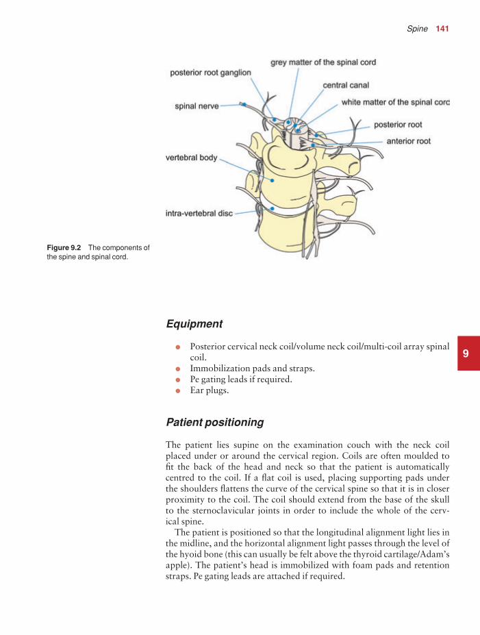
Spine 141
9
Equipment
• Posterior cervical neck coil/volume neck coil/multi-coil array spinalcoil.
• Immobilization pads and straps.• Pe gating leads if required.• Ear plugs.
Patient positioning
The patient lies supine on the examination couch with the neck coil placed under or around the cervical region. Coils are often moulded to fit the back of the head and neck so that the patient is automatically centred to the coil. If a flat coil is used, placing supporting pads under the shoulders flattens the curve of the cervical spine so that it is in closerproximity to the coil. The coil should extend from the base of the skull to the sternoclavicular joints in order to include the whole of the cerv-ical spine.
The patient is positioned so that the longitudinal alignment light lies inthe midline, and the horizontal alignment light passes through the level ofthe hyoid bone (this can usually be felt above the thyroid cartilage/Adam’sapple). The patient’s head is immobilized with foam pads and retentionstraps. Pe gating leads are attached if required.
Figure 9.2 The components ofthe spine and spinal cord.
9781405160858_4_009.qxd 28/05/2008 15:24 Page 141

142 Handbook of MRI Technique
Suggested protocol
Sagittal/coronal SE/FSE T1 or coherent GRE T2*
Acts as a localizer if three-plane localization is unavailable. The coronalor sagittal planes may be used.
Coronal localizer: Medium slices/gap are prescribed relative to the vert-ical alignment light, from the posterior aspect of the spinous processes to the anterior border of the vertebral bodies. The area from the base ofthe skull to the second thoracic vertebra is included in the image.
P 20 mm to A 30 mm
Sagittal localizer: Medium slice thickness/gap are prescribed on either side of the longitudinal alignment light, from the left to the right lateralborders of the vertebral bodies. The area from the base of the skull to thesecond thoracic vertebra is included in the image.
L 7 mm to R 7 mm
Sagittal SE/FSE T1 (Figure 9.3)
Thin slices/gap are prescribed on either side of the longitudinal alignmentlight, from the left to the right lateral borders of the vertebral bodies(unless the paravertebral areas are required). The area from the base ofthe skull to the second thoracic vertebra is included in the image.
L 22 mm to R 22 mm
Sagittal SE/FSE T2 or coherent GRE T2* (Figure 9.4)
Slice prescription as for Sagittal T1.
Axial/oblique SE/FSE T1/T2 or coherent GRE T2* (Figure 9.7)
Thin slices/gap are angled so that they are parallel to the disc space or perpendicular to the lesion under examination (Figures 9.5 and 9.6). Fordisc disease, three or four slices per level usually suffice. For larger lesionssuch as tumour or syrinx, thicker slices covering the lesion and a smallarea above and below may be necessary.
Additional sequences
Sagittal/axial oblique SE/FSE T1
Slice prescription as for Axial/oblique T2* with contrast enhancement fortumours.
Sagittal SE/FSE T2 or STIR
Slice prescription as for Sagittal T2*. An alternative to coherent GRE T2*.
9
9781405160858_4_009.qxd 28/05/2008 15:24 Page 142

9
Figure 9.3 Sagittal SE T1weighted midline image throughthe cervical spine.
Figure 9.4 Sagittal FSE T2weighted midline image throughthe cervical cord.
9781405160858_4_009.qxd 28/05/2008 15:24 Page 143

9
Figure 9.5 Sagittal FSE T2weighted image showing sliceprescription boundaries andorientation for axial imaging ofthe cervical cord.
Figure 9.6 Sagittal coherentGRE T2* weighted image of thecervical spine showingaxial/oblique slice positionsparallel to each disc space.
9781405160858_4_009.qxd 28/05/2008 15:24 Page 144

Spine 145
9
3D coherent/incoherent (spoiled) GRE T2*/T1
Thin slices and a few or medium number of slice locations are prescribedthrough the ROI. If PD or T2* weighting is desired, then a coherent orsteady-state sequence is utilized. If T1 weighting is required an incoherentor spoiled sequence is necessary. These sequences may be acquired in anyplane but, if reformatting is required, isotropic datasets must be acquired.
Sagittal SE/FSE T1 or fast incoherent (spoiled) GRE T1/PD
Slice prescription as for Sagittal T1, T2 and T2*, except neck in flexionand extension to correlate the potential relevance of spondylotic changesto signs and symptoms.
3D balanced gradient echo (BGRE) (Figure 9.8)
The contrast characteristics of a BGRE sequence provide for high signalfrom CSF (high T2 / T1 ratio) and thus produces images with high con-trast between CSF and nerve roots. It is important to remember that
Figure 9.7 Axial/obliquecoherent GRE T2* weightedimage through the cervical cord.
9781405160858_4_009.qxd 28/05/2008 15:24 Page 145
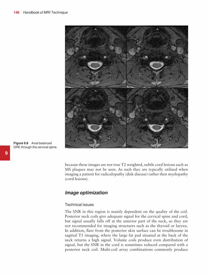
146 Handbook of MRI Technique
9
because these images are not true T2 weighted, subtle cord lesions such asMS plaques may not be seen. As such they are typically utilized whenimaging a patient for radiculopathy (disk disease) rather then myelopathy(cord lesions).
Image optimization
Technical issues
The SNR in this region is mainly dependent on the quality of the coil.Posterior neck coils give adequate signal for the cervical spine and cord,but signal usually falls off at the anterior part of the neck, so they are not recommended for imaging structures such as the thyroid or larynx. In addition, flare from the posterior skin surface can be troublesome insagittal T1 imaging, where the large fat pad situated at the back of theneck returns a high signal. Volume coils produce even distribution of signal, but the SNR in the cord is sometimes reduced compared with aposterior neck coil. Multi-coil array combinations commonly produce
Figure 9.8 Axial balancedGRE through the cervical spine.
9781405160858_4_009.qxd 28/05/2008 15:25 Page 146

Spine 147
9
optimum SNR, and may be used with a large FOV to include the thoracicspine. This strategy is important when pathology extends from the cerv-ical to the thoracic areas of the cord, e.g. syrinx.
Spatial resolution is also important, especially in axial/oblique imaging,as the nerve roots in the cervical region are notoriously difficult to visual-ize. Thin slices with a small gap and relatively fine matrices are employedto maintain spatial resolution. Ideally 3D imaging is used as this allowvery thin slices with no gap and the volume may be viewed in any plane(see Volume imaging in Parameters and trade-offs in Part 1). MultipleNEX/NSA are also advisable if the inherent SNR is poor. Therefore,unless FSE is utilized, scan times are often of several minutes duration.
Fortunately, a rectangular/asymmetric FOV is used very effectively insagittal imaging as the cervical spine fits into a rectangle with its longitud-inal axis running S to I. This facilitates the acquisition of fine matrices inshort scan times. With a reduced FOV in the phase direction, aliasing maybe a problem. In sagittal imaging, this artefact originates from the chinand the back of the head wrapping into the FOV. Increasing the size of theoverall FOV or utilizing oversampling (if available) may eliminate orreduce this artefact. In addition, spatial presaturation pulses brought intothe FOV to nullify signal coming from these structures are effective (seeFlow phenomena and artefacts in Part 1).
The multiple 180° RF pulses used in FSE sequences cause lengtheningof the T2 decay time of fat so that the signal intensity of fat on T2weighted FSE images is higher than in CSE. This sometimes makes thedetection of marrow abnormalities difficult. Therefore, when imaging thevertebral bodies for metastatic disease, a STIR sequence should be utilized(see Pulse sequences in Part 1).
Artefact problems
The cervical area is often plagued with artefact. Not only does aliasingfrom structures outside the FOV obscure the image, but the periodic, pulsatile, motion of CSF within the spinal canal produces phase ghosting.The speed of flow is usually quite rapid in the cervical region, and there-fore conventional flow-reducing measures, such as spatial presaturationand GMN, are less effective than in the lumbar region where CSF flow isslower. On T1 weighted images, spatial presaturation pulses placed S andI to the FOV are usually sufficient. However, on T2 weighted sequencesflow artefact is commonly troublesome. In addition, selecting an S–Iphase direction along with oversampling can also reduce CSF flow arte-fact in sagittal imaging.
As FSE sometimes demonstrates more flow artefact than CSE, it is usually not utilized in the cervical spine. This is especially true on T2weighted images where flow artefact can totally degrade the image.However, in cases where there is severe pathology such as a disc protru-sion, FSE often produces images that demonstrate acceptable levels ofartefact. This may be because the protruding disc locally slows down theCSF flow. In practice, it is probably worth trying FSE on the T2 images,
9781405160858_4_009.qxd 28/05/2008 15:25 Page 147

148 Handbook of MRI Technique
and only if the artefact is intolerable, repeat the scan using coherent GRE. However, FSE is not commonly recommended in axial/obliqueimaging because of flow-related problems. When using coherent GRET2* sequences, GMN should be implemented as this not only increasesthe signal from CSF, but also reduces artefact from CSF flowing down the canal within the slice. In addition the use of balanced GRE reducesflow artefact due to the implementation of balancing gradients (see Pulsesequences in Part 1). This rapid sequence also works well in 3D imagingas a large volume may be acquired in a short scan time. However the con-spicuity of nerve roots in the exit foramina may reduce when using a GREsequence due to the magnetic susceptibility effects. Pe gating minimizesartefact even further but, as the scan time is dependent on the patient’sheart rate, it is sometimes rather time-consuming. The implementation ofPe gating is therefore best reserved for cases of severe flow artefact thatcannot be reduced to tolerable levels by other measures.
Multiple NEX/NSA reduce artefact from signal averaging, but result inan increase in the scan time. Nevertheless their implementation is oftennecessary, especially where the SNR is poor, and flow artefact severe.Swallowing during data acquisition is a common source of artefact.Spatial presaturation pulses placed over the throat largely eliminate this,but care must be taken not to nullify signal from important anatomy.Another problem in the cervical region is truncation artefact (or Gibbsartefact) that produces a thin line of low signal in the cord and mimics asyrinx. Truncation artefact is reduced by selecting a higher phase matrix(see Flow phenomena and artefacts in Part 1).
Patient considerations
Some patients have difficulty placing their neck over the posterior neckcoil, especially in cases of fixed deformity. It is important that the neck is as close to the coil as possible to achieve maximum SNR. Placing pads under the patient’s shoulders flattens the spine, and therefore posi-tions the back of the neck nearer to the coil. Patients with cervical cordtrauma, cord compression, or tumours are often severely disabled. Themagnetic safety of any stabilization devices should be established beforethe examination. Great care must be taken when transferring these patientson to the examination couch, and they should be moved as little as possible.Due to excessively loud gradient noise associated with some sequences,ear plugs must always be provided to prevent hearing impairment.
Contrast usage
Contrast is not routinely given for disc disease. However, in cases of leptomeningeal spread of certain tumours such as medulloblastoma, con-trast is invaluable. Other cord lesions such as ependymomas and pine-aloblastomas also enhance well with contrast, as do infectious processesand active MS plaques. Bony tumours, especially those that return a low signal on T1 weighted images, enhance with contrast but this often
9
9781405160858_4_009.qxd 28/05/2008 15:25 Page 148

Spine 149
9
increases their signal intensity so that they are isointense with the sur-rounding vertebra. Under these circumstances, chemical/spectral pre-saturation or the Dixon technique should be implemented to reduce thesignal from fatty marrow in the vertebral bodies. Inversion recoverysequences that suppress fat (STIR) should not be used in conjunction withcontrast, as their inverting pulses may nullify the signal from the tumourthat, as a result of contrast enhancement, now has a similar T1 recoverytime to fat.
9781405160858_4_009.qxd 28/05/2008 15:25 Page 149

150 Handbook of MRI Technique
9
Thoracic spine
Common indications
• Thoracic disc disease.• Thoracic cord compression.• Visualization of a MS plaque in the thoracic cord.• Thoracic cord tumour.• To visualize the inferior extent of cervical syrinx.
Equipment
• Posterior spinal coil/multi-coil array spinal coil.• Pe gating leads if required.• Ear plugs.
Patient positioning
The patient lies supine on the examination couch with the spinal coilextending from the top of the shoulders to the lower costal margin toensure total coverage of the thoracic spine and conus. The patient is posi-tioned so that the longitudinal alignment light lies in the midline, and the horizontal alignment light passes through the centre of the coil, whichcorresponds approximately to the level of the fourth thoracic vertebra. Pegating leads are attached if required.
Suggested protocol
Sagittal/coronal SE/FSE T1 or coherent GRE T2*
Acts as a localizer if three-plane localization is unavailable. The coronalor sagittal planes may be used.
Coronal localizer: Medium slices/gap are prescribed relative to the vert-ical alignment light, from the posterior aspect of the spinous processes to the anterior border of the vertebral bodies. The area from the seventhcervical vertebra to the conus is included in the image.
P 40 mm to A 30 mm
Sagittal localizer: Medium slices/gap are prescribed on either side of thelongitudinal alignment light, from the left to the right lateral borders ofthe vertebral bodies. The area from the seventh cervical vertebra to theconus is included in the image.
L 7 mm to R 7 mm
9781405160858_4_009.qxd 28/05/2008 15:25 Page 150

Spine 151
9
Sagittal SE/FSE T1 (Figure 9.9)
Thin slices/gap are prescribed on either side of the longitudinal alignmentlight, from the left to the right lateral borders of the vertebral bodies(unless the paravertebral areas are required). The area from the seventhcervical vertebra to the conus is included in the image.
L 22 mm to R 22 mm
Sagittal SE/FSE T2 or coherent GRE T2* (Figure 9.10)
Slice prescription as for Sagittal T1.
Axial/oblique SE/FSE T1 or coherent gradient echo T2* (Figure 9.12)
Thin slices/gap are angled so that they are parallel to the disc space or perpendicular to the lesion under examination (Figure 9.11). For disc dis-ease, three or four slices per level usually suffice. For larger lesions such astumour or syrinx, thicker slices covering the lesion and a small area aboveand below are necessary.
Figure 9.9 Sagittal FSE T1weighted midline slice throughthe thoracic spine.
9781405160858_4_009.qxd 28/05/2008 15:25 Page 151

9
Figure 9.10 Sagittal FSE T2weighted midline slice throughthe thoracic cord.
Figure 9.11 Sagittal FSE T2weighted midline slice throughthe thoracic spine showing sliceprescription boundaries andorientation for axial imaging ofthe conus.
9781405160858_4_009.qxd 28/05/2008 15:25 Page 152

Spine 153
9
Additional sequences
Sagittal/axial/oblique SE/FSE T1 +/− contrast
For evaluating the conus and other cord lesions.
Image optimization
Technical issues
The SNR in this region is mainly dependent on the quality of the coil.Flare from the posterior skin surface may be troublesome, especially insagittal T1 imaging where the fatty tissues posterior to the thoracic spinereturn a high signal. In addition, there is signal fall-off from the anteriorpart of the chest due to its distance from the posteriorly situated coil. Forthis reason the posterior spinal coil is not utilized to image the thorax,unless the patient is a very small child. Phased array coils are useful to
Figure 9.12 Axial/oblique FSET2 weighted images through thethoracic cord.
9781405160858_4_009.qxd 28/05/2008 15:25 Page 153

154 Handbook of MRI Technique
image the whole of the cervical and thoracic cord whilst maintaining optimum SNR and resolution.
Spatial resolution is important especially in axial/oblique images, as thenerve roots in the thoracic region are commonly difficult to visualize.Thin slices with a small gap and relatively fine matrices are implementedto maintain spatial resolution. Multiple NEX/NSA are also advisable ifthe inherent SNR is poor. Therefore, unless FSE is utilized, scan times areusually of several minutes duration.
Fortunately, a rectangular/asymmetric FOV is used very effectively insagittal imaging as the thoracic spine fits into a rectangle with its longit-udinal axis running S to I. This facilitates the acquisition of fine matrices in short scan times. With a reduced FOV in the phase direction, aliasing may be a problem. In sagittal imaging, this artefact originates from theanterior chest wrapping into the FOV. Increasing the size of the overallFOV or utilizing oversampling (if available) may eliminate or reduce this artefact. In addition, spatial presaturation pulses brought into theFOV are effective (see Flow phenomena and artefacts in Part 1). In prac-tice, as a fairly large FOV is used to image the thoracic spine and there is signal fall-off in the anterior part of the chest, aliasing is not usuallytroublesome.
The multiple 180° RF pulses used in FSE sequences cause lengtheningof the T2 decay time of fat so that the signal intensity of fat on T2weighted FSE images is higher than in CSE. This sometimes makes thedetection of marrow abnormalities difficult. Therefore, when imaging the vertebral bodies for metastatic disease, a STIR sequence should be utilized.
Artefact problems
Flow from CSF pulsations commonly causes severe phase ghosting in the thoracic region, although the speed of flow is often less than in the cervical area. Spatial presaturation pulses placed S and I to the FOV arenecessary to reduce these flow-related problems. GMN also minimizesflow artefact but, as it increases the signal from CSF and the minimum TE available, it is usually reserved for T2 and T2* weighted sequences.FSE is commonly utilized in this area as the associated scan time reductionenables the implementation of very fine matrices. However, this sequenceoften demonstrates increased flow artefact compared with SE and GREsequences. Therefore, if flow artefact is too troublesome, SE or GRE maybe substituted.
Phase ghosting from cardiac and respiratory motion is the main sourceof artefact in the thoracic region. Spatial presaturation pulses broughtinto the FOV and placed over the heart and lung fields are very effective at reducing this. Pe gating minimizes artefact even further but, as the scan time is dependent on the patient’s heart rate, it is sometimes time-consuming. The implementation of Pe gating is therefore best reserved for cases of severe flow artefact that cannot be reduced to tolerable levelsby other measures.
9
9781405160858_4_009.qxd 28/05/2008 15:25 Page 154

Spine 155
9
In sagittal imaging, swapping the phase axis so that it runs from S to Iinstead of A to P removes the artefact from the cord. However, if there issignificant kyphosis, the artefact may still obscure the cervical and lumbarregions. In addition, if a rectangular/asymmetric FOV is implemented,swapping the phase axis places the longitudinal axis of the rectangle horizontally so that its benefits cannot be utilized. On newer systems it ispossible to use curved spatial presaturation pulses so that accurate place-ment of bands over the thoracic aorta is possible.
Due to the implementation of a small FOV in axial/oblique imaging,aliasing commonly occurs and therefore oversampling is necessary. Inaddition, phase artefact from movement of the lateral walls of the chestduring respiration, and some vessel pulsation, often interferes with theimages. Careful placement of spatial presaturation pulses A, R, and L ofthe FOV is usually effective at reducing this. RC is rarely necessary in thethoracic spine because the posteriorly situated spinal coil causes signalfall-off from the anterior chest wall, and therefore respiratory artefact isusually less troublesome than when imaging the whole chest in the bodycoil. Movement of the diaphragm is more significant, however, and RCmay be considered if this is a particular problem.
Patient considerations
Patients with cord trauma may be severely disabled and in great pain. The examination should obviously be undertaken as speedily as possibleunder these circumstances. Due to excessively loud gradient noise associ-ated with some sequences, ear plugs must always be provided to preventhearing impairment.
Contrast usage
Contrast is not routinely given for disc disease. However, in cases of leptomeningeal spread of certain tumours such as medulloblastoma, contrast is invaluable. Other cord lesions such as ependymomas andpinealoblastomas also enhance well with contrast, as do infectious pro-cesses and active MS plaques. Bony tumours, especially those that returna low signal on T1 weighted images, enhance with contrast but this often increases their signal intensity so that they are isointense with thesurrounding vertebra. Under these circumstances, chemical/spectral pre-saturation or the Dixon technique should be implemented to reduce the signal from fatty marrow in the vertebral bodies. STIR should not beused in conjunction with contrast, as its inverting pulse may nullify thesignal from the tumour that, as a result of contrast enhancement, now hasa similar T1 recovery time to fat.
9781405160858_4_009.qxd 28/05/2008 15:25 Page 155

156 Handbook of MRI Technique
9
Lumbar spine
Common indications
• Disc prolapse with cord or nerve root compression.• Spinal dysraphism (to assess cord termination, syrinx, diastemato-
myelia).• Discitis.• Evaluation of the conus in patients with appropriate symptoms.• Failed back syndrome.• Arachnoiditis.
Equipment
• Posterior spinal coil/multi-coil array spinal coil.• Foam pads to elevate the knees.• Ear plugs.
Patient positioning
The patient lies supine on the examination couch with their knees elev-ated over a foam pad, for comfort and to flatten the lumbar curve so thatthe spine lies nearer to the coil. The coil should extend from the xiphister-num to the bottom of the sacrum for adequate coverage of the lumbarregion. The patient is positioned so that the longitudinal alignment lightlies in the midline, and the horizontal alignment light passes just below thelower costal margin, which corresponds to the third lumbar vertebra.
Suggested protocol
Sagittal/coronal SE/FSE T1 or coherent GRE T2*
Acts as a localizer if three-plane localization is unavailable. The coronalor sagittal planes may be used.
Coronal localizer: Medium slices/gap are prescribed relative to the verticalalignment light, from the posterior aspect of the spinous processes to theanterior border of the vertebral bodies. The area from the conus to thesacrum is included in the image.
P 20 mm to A 30 mm
Sagittal localizer: Medium slices/gap are prescribed on either side of the lon-gitudinal alignment light, from the left to the right lateral borders of the verte-bral bodies. The area from the conus to the sacrum is included in the image.
L 7 mm to R 7 mm
9781405160858_4_009.qxd 28/05/2008 15:25 Page 156

Spine 157
9
Sagittal SE/FSE T1 (Figure 9.13)
Thin slices/gap are prescribed on either side of the longitudinal alignmentlight, from the left to the right lateral borders of the vertebral bodies(unless the paravertebral region is required). The area from the conus tothe sacrum is included in the image.
L 22 mm to R 22 mm
Sagittal SE/FSE T2 or coherent GRE T2* (Figure 9.14)
Slice prescription as for Sagittal T1.
Axial/oblique SE/FSE T1/T2 or coherent GRE T2* (Figure 9.16)
Thin slices/gap are angled so that they are parallel to each disc space andextend from the lamina below to the lamina above the disc. The lowerthree lumbar discs are commonly examined (Figure 9.15).
Figure 9.13 Sagittal FSE T1weighted midline slice throughthe lumbar spine showingnormal appearances.
9781405160858_4_009.qxd 28/05/2008 15:25 Page 157

9
Figure 9.14 Sagittal FSE T2weighted midline slice throughthe lumbar spine showingnormal appearances.
Figure 9.15 Sagittal FSE T2weighted midline slice showingslice prescription boundariesand orientation for axial/obliqueimaging of lumbar discs.
9781405160858_4_009.qxd 28/05/2008 15:25 Page 158

Spine 159
9
Additional sequences
Axial/oblique or Sagittal SE/FSE T1
With contrast for determining disc prolapse versus scar tissue in failedback syndrome, and for some tumours. Without contrast in spinal dysraph-ism. Chemical/spectral presaturation is beneficial to differentiate betweenfat and enhancing pathology.
Coronal SE/FSE T1
For cord tethering or alternative view of conus when sagittals are inconclusive.
Axial/oblique FSE T2
For arachnoiditis. As for Axial/obliques, except prescribe one slice through,and parallel to, each disc space and vertebral body from the sacrum to theconus (Figure 9.17).
Figure 9.16 Axial/oblique FSET2 weighted image of thelumbar spine.
9781405160858_4_009.qxd 28/05/2008 15:25 Page 159

160 Handbook of MRI Technique
9STIR
While FSE sequences provide excellent T2 weighted images of the spine, thesignal intensity from the normal fat in the marrow of the vertebral bodiesis generally high, even with longer TE times. For that reason, marrowpathology, such as tumours or fractures, may not be adequately visualizedon T2 weighted FSE sequences. A STIR sequence can be utilized to visual-ize bone marrow abnormalities better. This is demonstrated in the imagesin Figures 9.18–9.20. The T1 weighted FSE shows an acute fracture of theL-1 vertebral body. The T2 weighted FSE also shows the fracture but themajority of the bone marrow signal in the L1 vertebral body appears sim-ilar to the other vertebral bodies. The STIR clearly shows the increasedsignal within the L1 vertebral body consistent with an acute fracture.
Image optimization
Technical issues
The SNR in the lumbar region depends on the quality of the coil. Posteriorspinal coils return high signal in the area of the lumbar canal and vertebral
Figure 9.17 Sagittal FSE T2weighted image of the lumbarspine showing axial/obliqueslice prescription forarachnoiditis.
9781405160858_4_009.qxd 28/05/2008 15:25 Page 160

9
Figure 9.18 Sagittal T1weighted FSE showing an acute fracture in the body of L1.
Figure 9.19 Sagittal T2weighted FSE of the samepatient shown in Figure 9.18.
9781405160858_4_009.qxd 28/05/2008 15:25 Page 161

162 Handbook of MRI Technique
9bodies, but flare from the fatty tissues in the buttocks sometimes interfereswith the image. Phased array coils allow for imaging of the thoracic andlumbar spine in conjunction with good SNR and resolution. As CSF flow is reduced in this area, FSE is routinely used. This enables the imple-mentation of very fine matrices so that spatial resolution is significantlyincreased. Resolution is also maintained by using rectangular/asymmetricFOV in sagittal imaging (with the long axis of the rectangle running from S to I), and a small FOV in axial/oblique imaging. Fine matrices areespecially necessary in arachnoiditis to detect nerve root clumping.
Artefact problems
CSF pulsation is not usually troublesome as the speed of flow is relativelyslow. However, phase artefact from the aorta and the inferior vena cava(IVC), and lateral flow from the lumbar vessels, sometimes obscures thelumbar canal. Spatial presaturation pulses brought into the FOV andplaced S, I and A in the sagittal images, and A, R and L in the axial/obliqueimages, reduce phase ghosting. GMN minimizes flow artefact even fur-ther but, as it increases the signal in CSF and the minimum TE available, itis mainly reserved for the T2 and T2* weighted sequences.
Figure 9.20 Sagittal FSE-STIR of the same patient shownin Figure 9.18.
9781405160858_4_009.qxd 28/05/2008 15:25 Page 162

Spine 163
9
Swapping the phase axis in sagittal imaging so that it runs from S to I instead of A to P is probably the best way of removing this artefact from the cord. However, a rectangular/asymmetric FOV cannot be usedunder these circumstances as the long axis of the rectangle is placed hori-zontally (Figure 9.21). A compromise is to swap the phase axis and notuse a rectangular/asymmetric FOV in the T1 sagittal image, and keep thephase axis AP and use a rectangular/asymmetric FOV in the T2 sagittalimage.
With a reduced FOV in the phase direction, aliasing may be a prob-lem. In sagittal imaging, this artefact originates from the buttocks andabdomen wrapping into the FOV (Figure 9.22). Increasing the size of the overall FOV or utilizing oversampling (if available) may eliminate or reduce this artefact. If the phase axis is swapped, aliasing occurs as the areas superior and inferior to the coil are wrapped into the FOV andtherefore oversampling is necessary to avoid this. In addition, owing tothe implementation of a small FOV in the axial/oblique imaging, aliasingcommonly occurs and therefore oversampling is also required in thisplane. Spatial presaturation pulses brought into the FOV are also effective(Figure 9.23).
Figure 9.21 Sagittal FSE T1weighted images of the lumbarspine with phase A to P (left)and S to I (right). The definitionof the spinal cord is clearlyimproved on the right-handimage.
9781405160858_4_009.qxd 28/05/2008 15:25 Page 163

9
Figure 9.22 Sagittal FSE T2weighted midline slice throughthe lumbar spine usingrectangular/asymmetric FOV.Note phase aliasing from thebuttocks (arrow).
Figure 9.23 Correctplacement of spatial pre-saturation bands when usingrectangular/asymmetric FOV inthe lumbar spine.
9781405160858_4_009.qxd 28/05/2008 15:26 Page 164

Spine 165
9
The multiple 180° RF pulses used in FSE sequences cause lengthening ofthe T2 decay time of fat so that the signal intensity of fat on T2 weightedFSE images is higher than in CSE. This sometimes makes the detection ofmarrow abnormalities difficult. Therefore, when imaging the vertebralbodies for metastatic disease, a STIR sequence should be utilized.
Patient considerations
Many patients are in severe pain especially if they are suffering from aprolapsed lumbar disc. Make the patient as comfortable as possible withpads supporting their knees in a slightly flexed position. Small pads placedin the lumbar curve often help to alleviate sciatica and other types of back pain.
Due to excessively loud gradient noise associated with some sequences,ear plugs must always be provided to prevent hearing impairment.
Contrast usage
Contrast is used to distinguish disc prolapse from scar tissue post-operatively in failed back syndrome. These images are acquired with orwithout chemical/spectral presaturation. STIR should not be used withcontrast enhancement, as the contrast reduces the T1 value of damagedtissues so that it is similar to that of fat, and is therefore nullified by theinverting pulse. Scar tissue enhances immediately after the injection, butdisc material does not. However, about 20–30 min after the injection,disc material also enhances and therefore scanning should not be delayedafter the administration of contrast. In addition, the epidural veins andgranulation tissue at the periphery of a disc and fibrosis may enhance.Contrast is also invaluable to visualize suspicious lesions in the conus.
9781405160858_4_009.qxd 28/05/2008 15:26 Page 165

166 Handbook of MRI Technique
9
Whole spine imaging
Common indications
• Cord compression (level unknown), due to metastatic disease orprimary cord tumour.
• Bone marrow screening.• Congenital abnormalities of spinal curvature (scoliosis and kyphosis).• Evaluation of the extent of a syrinx.• Leptomeningeal disease.
Equipment
• Body coil/multi-coil array spinal coil.• Pe gating leads if required.• Ear plugs.
Patient positioning
The patient lies supine on the examination couch. The patient is posi-tioned so that the longitudinal alignment light lies in the midline, and thehorizontal alignment light passes through a point midway between thesacrum and the base of the skull (which corresponds to about 2 cm belowthe sternal notch). Pe gating leads are attached if required.
Suggested protocol
Sagittal SE/FSE T1 (Figure 9.24(a))
Thin slices/gap are prescribed on either side of the longitudinal alignmentlight, from the left to the right lateral borders of vertebral bodies (or pre-scribed graphically from a coronal localizer).
L 22 mm to R 22 mm
Include the entire canal from the base of the skull to below the sacrum anduse the largest FOV available. Repeat the scan if an area is missed. Ifsevere scoliosis is present, coronal images may be more beneficial thansagittals to assess the direction and extent of the curvature.
Sagittal SE/FSE T2 or coherent GRE T2* (Figure 9.24(b))
Slice prescription as for Sagittal T1.
9781405160858_4_009.qxd 28/05/2008 15:26 Page 166

Spine 167
9
Axial/oblique SE/FSE T1/T2
Thin slices/gap are prescribed through the ROI. Use a smaller local coilonce the ROI has been established (not necessary with a multi-coil array).In patients with severe spinal curvature, obliques may be performed toachieve orthogonal images.
Additional sequences
Sagittal SE/FSE T2 or STIR
For bone marrow screening, include the sternum in the image and addcoronals of the bony pelvis. Use chemical/spectral presaturation pulses inSE/FSE sequences.
Sagittal/oblique SE/FSE T1
With contrast for tumour infection and leptomeningeal disease.
Figure 9.24 Sagittal FSE T1 weighted image (left)and T2 weighted image (right) of the cervical and thoracic cord imaged using a phased array coil.
9781405160858_4_009.qxd 28/05/2008 15:26 Page 167

168 Handbook of MRI Technique
9
MR myelography/neurography (Figure 9.25)
Examination of nerve roots and peripheral nerves with high-resolutionimaging are useful additional techniques.
Image optimization
Technical issues
These examinations are often carried out to establish the level and causeof a cord compression. Therefore, spatial resolution is not necessarily as important as a quick diagnosis. The level of the compression may beunknown, and therefore coverage of the whole spinal canal is the mostimportant consideration. In the past this could only be achieved with thebody coil, as surface coils did not cover the entire spine. However, phasedarray coils have now been introduced that give the benefits of maximumcoverage and optimum SNR. If phased array coils are unavailable, thebody coil is implemented. This results in a loss of overall SNR and poorlocal spatial resolution, as a large FOV is utilized to cover the whole spine.
Figure 9.25 Sagittal obliquebalanced GRE through thecervical cord showing nerveroots and peripheral nerves.
9781405160858_4_009.qxd 28/05/2008 15:26 Page 168

Spine 169
Once a level has been established, the body coil may be substituted for asurface coil and higher-quality images obtained. This strategy is unneces-sary when using a multi-array as the increase in SNR enables acquisitionof images with adequate resolution. With both coil types, a rectangular/asymmetric FOV is used in the sagittal images to improve spatial resolu-tion with the long axis of the rectangle S to I.
Artefact problems
When imaging the entire spine with the body coil, artefacts are caused by CSF flow, heart and great vessel motion, and respiration. Spatial pre-saturation pulses placed S and I to the FOV reduce CSF artefact. They areoften also placed over the heart and great vessels but can obscure some of the spine if there is spinal curvature. However, on newer systems it ispossible to use curved spatial presaturation pulses that enable accurateplacement of the bands over the aorta. Spatial presaturation pulses arecommonly less effective over a large FOV and therefore phase ghostingmay still be evident. In addition, if chemical/spectral presaturation isemployed, it may be less effective than with a small FOV. This is becausethe energy of the presaturation pulse is now delivered to a greater volumeof tissue, thereby reducing its effectiveness. Additional shimming may berequired before chemical/spectral presaturation sequences.
GMN also minimizes flow artefact but, as it increases signal in CSF and the minimum TE available, it is usually only beneficial in T2 and T2*weighted sequences. Pe gating minimizes artefact even further but, as thescan time is dependent on the patient’s heart rate, it is sometimes time-consuming. The implementation of Pe gating is therefore best reserved for cases of severe flow artefact that cannot be reduced to tolerable levelsby other measures.
The multiple 180° RF pulses used in FSE sequences cause lengthen-ing of the T2 decay time of fat so that the signal intensity of fat on T2weighted FSE images is higher than in CSE. This sometimes makes thedetection of marrow abnormalities difficult. Therefore, when imaging the vertebral bodies for metastatic disease, a STIR sequence should be utilized.
Patient considerations
Patients with cord compression are sometimes severely disabled and inextreme pain. A swift examination is often necessary to avoid patientmovement. An analgesic administered prior to the examination may bebeneficial. Patients with severe curvature of the spine often find it impos-sible to lie flat on the examination couch. Patient comfort is very importantas these examinations are sometimes lengthy due to the extra sequencesneeded to achieve orthogonal images. It is wise to let the patient assumethe most comfortable position and use foam pads to support them. Theplane of the images is then adjusted to their position. Sometimes the lungfield area of these patients is compromised and respiration may become
9
9781405160858_4_009.qxd 28/05/2008 15:26 Page 169

170 Handbook of MRI Technique
an effort when they lie supine. Oxygen can be administered to the patientduring the examination, but reducing the scan time as much as possible isprobably the best remedy for this problem.
Due to excessively loud gradient noise associated with some sequences,ear plugs must always be provided to prevent hearing impairment.
Contrast usage
Contrast is often necessary especially for leptomeningeal disease, intraduralor extramedullary lesions and metastases. It may also be useful for spinalosteomyelitis.
9
9781405160858_4_009.qxd 28/05/2008 15:26 Page 170

10
10Lungs and mediastinum 173Heart and great vessels 182Thymus 195Breast 198Axilla 210Brachial plexus 213
Chest
171
9781405160858_4_010.qxd 28/05/2008 15:27 Page 171

172 Handbook of MRI Technique
10
Table 10.1 Summary of parameters. The figures given are general and should beadjusted according to the system used (Table 2.1)
Spin echo (SE)short TE min to 30 mslong TE 70 ms +short TR 300–600 mslong TR 2000 ms +
Fast spin echo (FSE)short TE min–20 mslong TE 90 ms +short TR 400–600 mslong TR 4000 ms +short ETL 2–6long ETL 16 +
Inversion recovery (IR) T1short TE min–20 mslong TR 3000 ms +medium TI 200–600 msshort ETL 2–6
STIRlong TE 60 ms +long TR 3000 ms +short TI 100–175 mslong ETL 12–20
FLAIRlong TE 60 ms +long TR 3000 ms +long TI 1700–2200 mslong ETL 12–20
Slice thickness2D thin 2–4 mm
medium 5–6 mmthick 8 mm
3D thin ≤ 1 mmthick ≥ 3 mm
FOVsmall ≤ 18 cmmedium 18–30 cmlarge ≥ 30 cm
NEX/NSAshort ≤ 1medium 2–3multiple ≥ 4
Coherent GRElong TE 15 ms +short TR ≤ 50 msflip angle 20°–40°
Incoherent GREshort TE min–5 msshort TR ≤ 50 msflip angle 20°–40°
Balanced GRETE minimumTR minimumflip angle ≥ 40°
SSFPTE minimumTR 40–50 msflip angle 20°–40°
Slice numbersVolumes small ≤ 32
medium 64large ≥ 128
Matrix (frequency ×× phase)coarse 256 × 128 or 256 × 192medium 256 × 256 or 512 × 256fine 512 × 512very fine ≥ 512 × 512
PC-MRA2D and 3D TE minimum
TR 25–33 msflip angle 30°
VENC venous 20–40 cm/sVENC arterial 60 cm/s
TOF-MRA2D TE minimum
TR 28–45 msflip angle 40°–60°
3D TE minimumTR 25–50 msflip angle 20°–30°
9781405160858_4_010.qxd 28/05/2008 15:27 Page 172

Chest 173
10
Lungs and mediastinum
Basic anatomy (Figure 10.1)
Figure 10.1 Anterior view ofthe components of the chestcavity.
Common indications
• Mediastinal lymphadenopathy.• Central and superior sulcus bronchial tumours.• Distinction between neoplasm and consolidated lung.• Alternative to CT of the mediastinum and chest wall when the
patient is hypersensitive to contrast medium.• Vascular evaluation of aortic dissection, pulmonary embolus, aortic
aneurysm or vascular stenosis.• Lung perfusion studies.• Assessment of diaphragmatic motion.
Equipment
• Body coil/volume torso multi-coil array.• RC bellows.• ECG or peripheral gating leads.• Ear plugs or headphones.
9781405160858_4_010.qxd 28/05/2008 15:27 Page 173

174 Handbook of MRI Technique
10
Patient positioning
The patient lies supine on the examination couch with the RC bellows (if required) and ECG gating leads attached. Pads can be placed under thepatient’s knees (for comfort) and beside the patient’s elbows (for optimalMR imaging). In some cases, if the patient is not comfortable supineand/or if the patient has trouble in confined spaces, prone positioning maybe a suitable alternative.
The patient is positioned so that the longitudinal alignment light lies in the midline, and the horizontal alignment light passes through the level of the fourth thoracic vertebra, or the nipples. The patient can be placedfeet first into the magnet if the ECG trace is unsatisfactory as this changesthe patient’s polarity relative to the main field (see Gating and respiratorycompensation techniques in Part 1).
Suggested protocol
Coronal breath-hold fast incoherent (spoiled) GRE/SE T1 (Figure 10.2)
Acts as a localizer if three-plane localization is unavailable, or as a diag-nostic sequence. Medium slices/gap are prescribed relative to the vertical
Figure 10.2 Coronal breath-hold incoherent (spoiled) GRET1 of the chest showingprescription of axial slices.
9781405160858_4_010.qxd 28/05/2008 15:27 Page 174

Chest 175
10
alignment light, from the posterior chest muscles to the sternum. Theentire lung fields from apex to base are included in the image. As the chestanatomy is generally located more anteriorally than posteriorly, slices areoffset in the anterior direction.
P 60 mm to A 80 mm
Axial FSE T1/incoherent (spoiled) GRE T1 (Figures 10.3–10.5)
As for the Coronal T1, except slice thickness/gap is adjusted to fit theROI. Prescribe slices from the diaphragm to the apex of the lung orthrough the ROI.
Axial FSE PD/T2/SS-FSE T2/GRE T2* (Figure 10.6)
Slice prescription as for Axial T1.Useful to characterize active tissue such as distinguishing tumour from
consolidated lung and to evaluate fluid pneumonia or pleural effusion.
Figure 10.3 Axial SE T1weighted gated image of thechest or axial imaging.
9781405160858_4_010.qxd 28/05/2008 15:27 Page 175

10
Figure 10.4 Axial FSE T1weighted image through thechest showing a large lesion inthe left lung.
Figure 10.5 Axial incoherentGRE T1. Same slice as Figure 10.4.
9781405160858_4_010.qxd 28/05/2008 15:27 Page 176

Chest 177
10
Figure 10.6 Axial SS-FSE.Same slice as shown in Figure 10.4.
Additional sequences
Perfusion studies
Lung perfusion can be evaluated by either administering contrast or with‘spin tagged perfusion’ techniques. In these cases contrast is ‘tagged’ witheither contrast or arterial spin tagging applied in the midline of the patientin an attempt to saturate blood flowing from the heart and into the lungsby way of the pulmonary arteries.
Ventilation studies
This study is analogous to the VQ scan offered in Nuclear Medicine. Thepatient breathes in hyperpolarized helium gas and holds their breath,while images are acquired.
Coronal fast incoherent (spoiled) GRE T1/SS-FSE T2
These sequences can be used during respiration to assess motion of thediaphragm. In this case, slices are acquired during normal respiration andreplayed as a movie or cine loop.
9781405160858_4_010.qxd 28/05/2008 15:27 Page 177

178 Handbook of MRI Technique
10
Image optimization
Technical issues
The chest has a relatively poor SNR as the proton density of the lung fieldsis low. In addition, there is little fat to give good contrast. The implementa-tion of a volume array coil helps maintain SNR. This is especially usefulwhen thinner slices and a finer matrix are required. Chest imaging can beperformed with a number of RF coil designs. Although the body coil isnotorious for lower SNR, it can be utilized for large areas of coverage.Also, the body coil is acceptable in cases where contrast is the main determining factor in image contrast, such as MRA of the aorta or thepulmonary arteries. For the most part therefore the body coil will produceoptimum images for chest imaging. For higher SNR, higher resolutiontorso array coils should be used (see Heart and great vessels).
The use of multiple NEX/NSA not only reduces some respiratory andcardiac artefact because of signal averaging, but also improves the SNRdue to increased data collection. The disadvantage of this strategy is theassociated increase in scan time, although this can be compensated for, tosome degree, by the implementation of a coarser matrix or a rectangular/asymmetric FOV. SE T1 weighted sequences are traditionally used to showanatomy and black blood. GRE sequences are useful for the evaluation offlow, and T2 weighted sequences demonstrate pathology and free fluid.On some systems FSE is not compatible with RC techniques that use phasereordering. Under these circumstances SE sequences can be substituted.
Artefact problems
Respiratory, cardiac and flow motion are the most obvious artefacts inthe chest. Image quality can be compromised by physiologic motion fromthe lungs and heart, from flowing blood within vessels and, in some cases,from the oesophagus and stomach. Compensation for physiologic motionartefacts in the chest can be reduced by a number of imaging optionsincluding: respiratory compensation, breath-hold techniques, cardiac gating, cardiac triggering or other imaging options (saturation pulses orgradient moment nulling). Breath-hold techniques are achieved by theacquisition of rapid imaging sequences (20 seconds or less) and instruct-ing the patient to hold their breath during the image acquisition.
Motion artefact will always occur along the phase encoding axis, andthe degree to which they interfere with the image is mostly due to theproficiency of the respiratory compensation techniques used and ECGgating. For respiratory gating and/or respiratory triggering, a respiratorymonitoring device, known as a bellows is placed around the patient’schest or abdomen. Placement can be determined by the patient’s breath-ing style. If, for example patient respiratory motion is generated bymotion in the chest, then the bellows should be placed there. However, if the patient’s motion occurs more within the abdomen, the bellowsshould be located in the abdominal region. (For more information about
9781405160858_4_010.qxd 28/05/2008 15:27 Page 178

Chest 179
10
bellows placement, see Respiratory compensation techniques in Part 1).Alternatively, breath-hold techniques may be used to suspend respiration.Check that the ECG leads are correctly attached and that the ECG tracehas good amplitude and is triggering correctly (see Gating and respiratorycompensation techniques in Part 1). When implemented properly, ECGgating effectively reduces cardiac motion artefact. However, if ECG gat-ing is inefficient, image quality is compromised.
The phase encoding direction is generally prescribed by the system andthus defaults along a given direction. For the most part, the phase direc-tion defaults along the short axis of the anatomy. Therefore the phaseencoding axis usually lies A to P on axial images and R to L on coronals.Swapping the phase axis to R to L on the axial scans and S to I on coronalsis occasionally beneficial to remove artefact from the area of interest. Forexample, the phase direction for axial chest imaging generally defaults to a position anterior to posterior direction. However, if the motion arte-fact ‘streaks’ across anatomy or pathology of interest, swapping phaseand frequency directions can be selected to ‘relocate’ the motion artefactto a position right to left across the image (Figures 10.7 and 10.8). As this strategy positions the long axis of the anatomy along the phase axis,oversampling is necessary to avoid aliasing. Furthermore, caution should
Figure 10.7 Axial FSE T1weighted image of the chestwith phase anterior to posterior.
9781405160858_4_010.qxd 28/05/2008 15:28 Page 179

180 Handbook of MRI Technique
10be used if rectangular FOV has also been selected as the short axis of the rectangle is located along the phase direction. Therefore as the phasedirection is swapped, so is the direction of the rectangle.
Spatial presaturation pulses are also important to reduce flow artefactfurther. They are placed S and I to the FOV to decrease artefact from theaorta and IVC. R and L spatial presaturation pulses are beneficial in coronal images to decrease artefact from venous flow entering the chestfrom the subclavian vessels. In addition, when used in conjunction withSE or FSE sequences, spatial presaturation pulses produce black blood(see Figure 10.18). If signal persists in a vessel it may indicate either slow flow or occlusion. GMN reduces flow artefact further but, as it alsoincreases the signal in vessels and the minimum TE available, it is not usually beneficial in T1 weighted sequences unless contrast agents havebeen administered. When used in conjunction with GRE sequences,GMN produces bright blood (see Figure 10.18). If low signal is seenwithin the vessel, it may indicate either slow flow or occlusion. In additionconsideration should be given to the fact that when a structure is brightand it moves during MR image acquisition, it can ‘streak’ across the MRimage in the phase direction.
Figure 10.8 Axial FSE T1weighted image of the chestwith phase left to right.
9781405160858_4_010.qxd 28/05/2008 15:28 Page 180

Chest 181
10
Patient considerations
Patients having this kind of investigation are often breathless; thereforeminimizing the scan time is important. However, if the patient has a slowheart rate or a poor cardiac output, the system cannot always trigger off every R wave, thereby lengthening the scan time considerably. Underthese circumstances limiting the number of sequences is beneficial, andcontinuous reassurance of the patient may steady their heart rate and respiration. In addition, patient monitoring is recommended for patientswho are short of breath and the administration of oxygen may be required.Due to excessively loud gradient noise associated with some sequences,ear plugs must always be provided to prevent hearing impairment.
Contrast usage
Contrast can be given to enhance lung, mediastinal or hilar masses. Thismay be helpful to increase the conspicuity of pathology in an area withlow inherent contrast and to visualize pleural inflammation. Contrast canalso be useful for visualizing chest vessels. Gaseous agents such as hyper-polarized helium gas are under investigation for the evaluation of lungventilation during inhalation.
9781405160858_4_010.qxd 28/05/2008 15:28 Page 181

182 Handbook of MRI Technique
10
Heart and great vessels
Basic anatomy (Figure 10.9)
Figure 10.9 The great vesselsand chambers of the heart.
Common indications
• Thoracic aortic aneurysm, dissection, and coarctation.• Complex congenital abnormalities of the heart and great vessels.• Atrial or ventricular septal defect.• Assessment of ventricular function.• Assessment of ventricular muscle mass.• Vessel patency and thrombus.• Valvular dysfunction.
Equipment
• Body coil/volume torso array coil.• RC bellows.• ECG gating leads.• Ear plugs.
9781405160858_4_010.qxd 28/05/2008 15:28 Page 182

Chest 183
10
Patient positioning
The patient lies supine on the examination couch with the RC bellows (if required) and ECG gating leads attached. If breath-hold technique isnot possible, respiratory gating or triggering is recommended to reducethe respiratory artefacts. The patient is positioned so that the longitudinalalignment light lies in the midline, and the horizontal alignment lightpasses through the level of the fourth thoracic vertebra, or the nipples.The patient can be placed feet first into the magnet if the ECG trace isunsatisfactory to change the polarity of the patient relative to the mainfield of the magnet (see Gating and respiratory compensation techniquesin Part 1).
Suggested protocol
A three-plane localizer is optimal as the heart and vascular structures ofthe chest lie obliquely within the cavity of the chest. The images providedin three orthogonal planes provide a localizer so that oblique views of theheart and great vessels can be prescribed.
Coronal breath-hold fast incoherent (spoiled) GRE/SE T1 (Figure 10.10)
Acts as a localizer if three-plane localization is unavailable, or as a diag-nostic sequence. Medium slices/gap are prescribed relative to the verticalalignment light, from the posterior chest muscles to the sternum. The areafrom the top of the sternum to the diaphragm is included in the image.
P 60 mm to A 80 mm
Axial SE/FSE T1 (Figure 10.11)
As for the Coronal T1, except slice thickness/gap is altered to fit the ROI.Prescribe slices from the inferior border of the heart to the superior aspectof the arch of the aorta (Figure 10.10).
Specific cardiac views
Long Axis view (two chamber): From the axial T1 projection, using a slice through the left ventricle, align the slice slab parallel to the intra-ventricular septum and ensure the slab covers the whole of the left ventricle (Figures 10.12 and 10.13).
Four chamber view: from the long axis view align through the apex ofthe left ventricle and the mitral valve. Ensure the slice slab covers thewhole of the left ventricle. This plane can also be acquired from the shortaxis view (Figures 10.14 and 10.15).
Short Axis view: from the long axis view align perpendicular to the longaxis view imaging plane so that the alignment is parallel to the mitral
9781405160858_4_010.qxd 28/05/2008 15:28 Page 183

10
Figure 10.10 Coronal SE T1weighted image through thechest cavity demonstrating sliceprescription boundaries andorientation for axial imaging ofthe heart.
Figure 10.11 Axial T1weighted FSE image of thechest using cardiac gating.
9781405160858_4_010.qxd 28/05/2008 15:28 Page 184

10
Figure 10.12 Axial FSE T1weighted image showing slice orientation for the long axis view.
Figure 10.13 Two chamberlong axis view.
9781405160858_4_010.qxd 28/05/2008 15:28 Page 185

10
Figure 10.14 Long axis withslice orientation and sliceboundaries for the four chamber view.
Figure 10.15 Four chamberview.
9781405160858_4_010.qxd 28/05/2008 15:28 Page 186

Chest 187
10valve. Ensure the slice slab covers the whole of the left ventricle (Figures10.16 and 10.17). The short axis plane can also be prescribed from thecoronal localizer. A location can be identified on the coronal localizer,posterior at the aortic root; and another on the coronal by paging theslices anteriorally to the apex of the heart. Once these locations areknown, the short axis can be prescribed by explicitly identifying the loca-tions. The scanner will essentially draw an imaginary line between thepoints and scan perpendicular to that imaginary line. The four chamberview can also be acquired from the short axis view by orientating the sliceprescription through the left and right ventricles angled parallel to thediaphragm.
Sagittal/oblique SE T1
As for Axial SE T1, except slices are angled through the ascending anddescending aorta and prescribed from one lateral edge of the vessel wall tothe other.
This sequence is used to visualize the ascending and descending aorta in one view (candy cane or walking stick view). Select an image from the
Figure 10.16 Long axis withslice orientation and sliceboundaries for the short axis view.
9781405160858_4_010.qxd 28/05/2008 15:28 Page 187

188 Handbook of MRI Technique
10axial series that demonstrates both portions of the aorta. Check slice posi-tion on a more superior slice that demonstrates the arch.
Black blood imaging vs bright blood imaging (Figure 10.18)
SE or FSE images are generally acquired with saturation pulses for theevaluation of black blood. Gradient echo, PC or EPI imaging sequencescan be acquired with GMN for the evaluation of bright blood. Otherblack blood imaging techniques utilize a modified inversion recoverysequence, known as Double IR or Triple IR. Although the various ven-dors have unique acronyms for these sequences, the premise is the same.In each case the sequence begins with one 180° RF pulse followed byanother 180° RF (double IR). In this case the sequence has essentially beendriven to equilibrium. Since flowing blood does not stay within the slicefor enough time to experience both 180° RF pulses, flowing blood appearsblack. In triple IR sequences, the double IR sequence has an additional180° pulse at the frequency of fat for spectral presaturation. In this case,the suppression of epicardial fat combined with black flow within the cavity of the heart, allows for better visualization of the myocardium.
Figure 10.17 Short axis view.
9781405160858_4_010.qxd 28/05/2008 15:28 Page 188

Chest 189
10Oblique incoherent (spoiled) GRE T1 or coherent GRE T2* multiphase (cine)
Images of the heart, acquired during multiple phases of the cardiac cycleprovide cardiac images during the beating of the heart. This technique is known as multiphase imaging. The more slices acquired within eachcardiac cycle, the better the temporal resolution (resolution over time).For cardiac imaging temporal resolution, particularly in multiphase imag-ing, is limited by scan time. For example, if 16 phases of the cardiac cycleare to be acquired during one phase of the cardiac cycle this means thatthese images are acquired at the same slice location, but at different timesduring the cardiac cycle R–R interval.
Cardiac cine (like multiphase imaging) is used to assess cardiac func-tion. The most common views for cardiac cine images are the short axisview or the straight axial view of the chest. This view is generally used to evaluate the left ventricle. For other areas of the heart, two chamber or four chamber views may be utilized. Two chambers are best demon-strated on a sagittal/oblique view, four chambers in the coronal/oblique
Figure 10.18 Axial imagesshowing bright blood imaging(above) and black bloodimaging (below) of the greatvessels.
9781405160858_4_010.qxd 28/05/2008 15:28 Page 189

190 Handbook of MRI Technique
plane. Additional views such as the left ventricular outflow technique mayalso be useful.
Medium slices/gap are prescribed in the plane relevant to the ROI(often axial or oblique). Select the cine functions as appropriate to the system, i.e. number of slices and phases per acquisition (see Gating andrespiratory compensation techniques in Part 1).
Additional sequences
SPAMM tagging
SPAMM (spatial modulation of magnetization) essentially modulates or varies the magnetic field in the region of the heart, like waves. Since theRF pulse is dependent upon the magnetic field, RF excitation pulses onlyexcite tissues with the same frequency. Therefore the RF pulses match forexample the peaks of the waves but not the valleys. The effect is a signal inthe location of the RF match (resonance) and no signal in the areas wherethe RF pulse does not match the frequency. Modulation can be appliedalong several directions. If one direction is used stripes appear across theimages. If modulation is applied along two perpendicular axes, then theresultant image has a grid-like appearance. The choice between stripesand grids is generally at the discretion of the radiologist.
This technique is used in conjunction with multiphase or fast cardiac SEor GRE sequences to assess myocardial wall function post-myocardialinfarction. The SPAMM technique used with multiphase imaging enablesvisualization of the SPAMM stripes or grid that appear to move with themyocardium. In fact the stripes or grids not only move, but tend to fadeaway over time, during the cardiac motion in normal myocardium (orheart wall muscle). However in areas of myocardial infarction, the heartwall muscle does not move normally. SPAMM images therefore yieldstripes or grids that persist rather than fade. This provides informationabout heart function.
SPAMM sequences, used in conjunction with cine PC, show promisefor real-time imaging of the heart. In addition, PC images can be recon-structed as magnitude images or phase images. Magnitude images arereconstructed like MR images, where phase data are utilized to producephase images. Phase images provide directional information about heartwall motion and flow direction.
EPI
This sequence, used in conjunction with cine PC, shows promise for real-time imaging of the heart and coronary vessels. In addition, EPI imaging isacquired with rapid imaging times for the reduction in motion artefacts.However EPI is plagued with image artefacts such as chemical shift, andsusceptibility.
10
9781405160858_4_010.qxd 28/05/2008 15:28 Page 190

Chest 191
10Contrast enhanced cardiac and vascular studies (Figure 10.19)
Gadolinium enhanced GRE sequences of the heart can be used to demon-strate masses or infarcts of the heart as well as vasculature of the chest and heart. GRE with contrast enhancement, provide images with high signal in areas of flowing blood. MRA sequences, acquired with a sagittaloblique or the ‘candy cane shot’ of the aortic arch, can demonstrate com-parison views of the aortic dissection.
Typically for the evaluation of the aortic arch, sagittal or sagittaloblique sequences are acquired. However, for the evaluation of the pul-monary arteries, the coronal plane is optimal. Pulmonary MRA sequencesare acquired with dynamic contrast enhancement. For coronary arteryimaging, high resolution, multiple oblique images with dynamic contrastenhancement are required for bright blood imaging (Figure 10.20).
Cardiac perfusion studies
In some cases, cardiac perfusion studies are used with, and without, phar-macologic (stress inducing) agents for the evaluation of cardiac function.
Figure 10.19 Coronal fastincoherent (spoiled) GRE T1weighted image acquired aftercontrast enhancement.
9781405160858_4_010.qxd 28/05/2008 15:28 Page 191

192 Handbook of MRI Technique
10
One such agent is known as Dobutamine™. This agent produces cardiac stress and therefore imaging can be acquired during pharmaco-logically induced stress and while the heart is at rest. Such agents how-ever, may not be approved for use in MRI. For this reason caution shouldbe taken in performing MR cardiac imaging during pharmacologicallyinduced stress.
Diffusion imaging
Recent studies using diffusion tensor imaging to visualize the myocardiumshow some promise but require very strong and fast gradients.
Image optimization
Technical issues
As the chest has a relatively poor SNR, the implementation of a volumearray coil helps maintain SNR. This is especially useful because thinnerslices and a finer matrix are required for high-resolution imaging of
Figure 10.20 Coronary arteryimaging after contrastenhancement.
9781405160858_4_010.qxd 28/05/2008 15:28 Page 192

Chest 193
10
the heart. Remember however that the FOV is limited to the size of thecoil. For smaller structures such as the heart and coronary arteries, multi-channel coils or phased array coils for improved SNR are recommendedas they permit smaller voxels and therefore higher resolution. The use ofmultiple NEX/NSA not only reduces some respiratory and cardiac arte-fact, but also improves the SNR. The disadvantage of this strategy is theassociated increase in scan time. This can be compensated for, to somedegree, by the implementation of a coarser matrix.
Artefact problems
Respiratory, cardiac and flow motion are the most obvious artefacts inthe chest. They occur along the phase encoding axis, and the degree towhich they interfere with the image is mostly due to the proficiency of RC and ECG gating. Ensure the RC bellows are properly connected and are working efficiently. Alternatively, breath-hold techniques may beused to suspend respiration. Check that the ECG leads are correctlyattached and that the ECG trace has good amplitude and is triggering correctly (see Gating and respiratory compensation techniques in Part 1)(Figure 10.21).
Figure 10.21 Axial imagesthrough the heart withoutcardiac gating (above) and with cardiac gating (below).
9781405160858_4_010.qxd 28/05/2008 15:29 Page 193

194 Handbook of MRI Technique
10
Spatial presaturation pulses are also important to further decrease flowartefact. They are placed S and I to the FOV to reduce flow artefact fromthe aorta and IVC. R and L presaturation pulses are beneficial in coronalimages to decrease artefact from venous flow entering the chest from thesubclavian vessels. When used in conjunction with SE sequences, spatialpresaturation pulses produce black blood. If signal is seen within a vesselits may indicate either slow flow or occlusion. GMN reduces flow artefactfurther and is mainly used in cine imaging (see Gating and respiratorycompensation techniques in Part 1). It is not commonly utilized in T1weighted SE sequences as it increases signal in vessels and the minimumTE available. When used in conjunction with coherent GRE sequences,GMN produces bright blood. If a signal void is seen within a vessel, it mayindicate either slow flow or occlusion.
Patient considerations
Patients who undergo MRI of the heart generally have cardiac problems.These patients should be closely monitored for cardiac function withpulse oximetry.
Also the cardiac gating leads, and hence the ECG tracing that isdetected from these leads, may have been altered by the manufacturer to reduce the effect of the elevated ‘T’ wave caused by the magnetic field.This effect is known as the magnet–haemodynamic effect or the magnet–hydrodynamic effect. If the patient has a slow heart rate or a poor cardiacoutput, the system cannot always trigger off every R wave, therebylengthening the scan time considerably. Under these circumstances limit-ing the number of sequences is beneficial, and continuous reassurance of the patient may steady their heart rate and respiration. Oxygen can alsobe administered for patients who are, or who become, short of breath. Dueto excessively loud gradient noise associated with some sequences, hear-ing protection in the form of head phones or ear plugs is recommended toprevent hearing impairment.
Contrast usage
Contrast is routinely given for imaging the heart and great vessels in conjunction with fast GRE sequences and dynamic imaging of the heart,aortic arch, great vessels, pulmonary arteries and coronary arteries (seeFigures 10.19 and 10.20). Double or triple doses may improve vascularvisualization. In addition, cardiac masses can be sometimes well visual-ized after contrast enhancement.
9781405160858_4_010.qxd 28/05/2008 15:29 Page 194

Chest 195
10
Thymus
Common indications
• Thymic evaluation of myasthenia gravis.• Evaluation of thymic masses in general.• Evaluation of the post-operative mediastinum.
Equipment
• Body coil/volume torso array coil.• RC bellows.• ECG gating leads.• Ear plugs.
Patient positioning
The patient lies supine on the examination couch with the RC bellows (if required) and ECG gating leads attached. The patient is positioned sothat the longitudinal alignment light lies in the midline, and the horizontalalignment light passes through the level of the sternum. The patient can beplaced feet first into the magnet if the ECG trace is unsatisfactory (seeGating and respiratory compensation techniques in Part 1).
Suggested protocol
Sagittal breath-hold fast incoherent (spoiled) GRE/SE T1
Acts as a localizer if three-plane localization is unavailable, or as a diag-nostic sequence. Medium slices/gap are prescribed on either side of thelongitudinal alignment light. The area from the diaphragm to the apex ofthe lung is included in the image.
L 15 mm to R 15 mm
Axial SE T1
Medium slices/gap are prescribed through the thymus
Axial SE T1 + contrast
As for Axial SE T1, except use chemical/spectral presaturation to distin-guish enhancing pathology from fat.
9781405160858_4_010.qxd 28/05/2008 15:29 Page 195

196 Handbook of MRI Technique
10
Additional sequences
Axial SE/FSE T2
Slice prescription as for Axial T1.
Image optimization
Technical issues
The chest has a relatively poor SNR as the proton density of the lung fieldsis low. In addition, there is little fat to give good contrast. The implemen-tation of a volume array coil helps maintain SNR. This is especially usefulwhen thinner slices and a finer matrix are required. The use of multipleNEX/NSA not only reduces some respiratory and cardiac artefact becauseof signal averaging, but also improves the SNR due to increased data collection. The disadvantage of this strategy is the associated increase in scan time, although this can be compensated for, to some degree, by theimplementation of a coarser matrix. On some systems FSE is not com-patible with RC techniques that use phase reordering. However, in con-junction with multiple NEX/NSA and a rectangular/asymmetric FOV, itsimplementation often increases both the resolution and SNR, and can bebeneficial in examinations of the thymus.
Artefact problems
Respiratory, cardiac and flow motion are the most obvious artefacts inthe chest. They occur along the phase encoding axis, and the degree towhich they interfere with the image is mostly due to the proficiency of RCand ECG gating. Ensure the RC bellows are properly connected and areworking efficiently. Alternatively, breath-hold techniques may be used tosuspend respiration. Check that the ECG leads are correctly attached andthat the ECG trace has good amplitude and is triggering correctly (seeGating and respiratory compensation techniques in Part 1). When imple-mented properly, ECG gating effectively reduces cardiac motion artefact.However, if ECG gating is inefficient, image quality is compromised.
The phase encoding axis usually lies A to P on axial images so that anyphase ghosting interferes with the anteriorly situated thymus. It is there-fore necessary to swap the phase axis to R to L to remove artefact fromthe thymus gland. This strategy positions the long axis of the anatomyalong the phase axis, therefore oversampling is necessary to avoid aliasing,especially if the FOV is small (see Flow phenomena artefacts in Part 1).
Spatial presaturation pulses are also important to reduce flow artefactfurther. They are placed S and I to the FOV to decrease flow artefact fromthe aorta and IVC. GMN reduces flow artefact further but, as it alsoincreases signal in vessels and the minimum TE available, it is not usually
9781405160858_4_010.qxd 28/05/2008 15:29 Page 196

Chest 197
10
beneficial in T1 weighted sequences. Additional shimming may be requiredbefore chemical/spectral presaturation sequences.
Patient considerations
Thymus imaging is generally acquired on paediatric patients as the thymus gland shrinks as the child matures. For this reason, sedation maybe considered, depending upon the age of the child.
Patients are made as comfortable as possible and a careful explanationof the examination is important. If the patient is nervous, their ECG traceis often affected, thereby reducing the effectiveness of ECG gating. Underthese circumstances continuous reassurance of the patient may steadytheir heart rate and respiration, and improve the efficiency of gating. Dueto excessively loud gradient noise associated with some sequences, earplugs must always be provided to prevent hearing impairment.
Contrast usage
Contrast is often administered to improve the visualization of the thymusgland. This strategy is especially useful in conjunction with chemical/spectral presaturation pulses.
9781405160858_4_010.qxd 28/05/2008 15:29 Page 197

198 Handbook of MRI Technique
10
Breast
Basic anatomy (Figure 10.22)
Figure 10.22 Sagittal sectionthrough the breast.
Common indications
For breast lesions
• Screening for high risk patients• Staging of benign and malignant disease.• Characterization of abnormalities in patients with breast implants.• When conventional or digital is not optimal.• Characterization of abnormalities in patients with very fatty or
dense breasts.
9781405160858_4_010.qxd 28/05/2008 15:29 Page 198

Chest 199
For breast implants
• Implant rupture (linguine sign).• Known rupture (intra-capsular vs. extra-capsular)• Implanted patients with lesions
Equipment
• Breast coil(s) either single, double or phased array.• Extension tubing, needle, contrast (MR-compatible biopsy needles
if MR interventional procedure is planned).• A magnetically safe automatic injector if available.• Ear plugs.
Patient positioning
Patient positioning includes the patient lying prone, with breasts posi-tioned within the breast coil. Exact patient position generally dependsupon the method used for breast imaging. Some imaging centres choose to utilize the so called ‘European Method’, whereas others choose to dothe so called ‘US Method’ (see later in Technical considerations). Whenevaluating lesions with the US method, images are acquired in the sagittalplane, one breast at a time. The European method acquires images in theaxial plane imaging both breasts simultaneously.
The patient is positioned so that the longitudinal alignment light lies inthe midline, and the horizontal alignment light passes through the centreof the coil(s). For vertical field systems, breasts should be raised to isocen-tre in the anterior/posterior direction. This ensures that the breast is in themost homogeneous portion of the magnetic field, and therefore optimizesfat suppression on post-contrast images.
If contrast is given during the examination (for evaluation of breastlesions), a needle is inserted into the antecubital fossa prior to the exam-ination. The contrast can then be administered through extension tubingso that patient movement is minimized during the injection. Alternatively,a magnetically safe automatic injector can be used if available. Powerinjectors are capable of delivering injections of consistent timing anddose. This becomes particularly useful for the evaluation of breast lesionswhen followed up. Furthermore, since the haemodynamics of the breastlesion is one determining factor for benign versus malignant lesions, con-sistent timing and dose of gadolinium contrast injection is important (seeDynamic imaging under Pulse sequences in Part 1).
A note on compression: Many breast lesions are associated with a largevascular supply that results in thick blood vessels known as neovascular-ity and angiogenesis. This neovascularity and angiogenesis result in highblood flow to the lesions known as hypervascularity. The hypervascu-larity of breast cancers causes rapidly enhancing lesions of the breast.
10
9781405160858_4_010.qxd 28/05/2008 15:29 Page 199

200 Handbook of MRI Technique
10
Overcompression of the breast may result in reduction in the visualizationof some breast lesions. This occurs because the vascularity of some lesionsis reduced upon compression and therefore will not enhance. Some coilshave a compression device built into their design. When evaluating implants,and/or when using the European method, compression is not required.When using the US method the breast is reshaped (gently compressed) toreduce the number of slices required to cover the whole breast in a singleacquisition. This provides dynamic images of the breast in acceptableimaging times. Some coils have a compression device built into their design.
Suggested protocol for the US method
Three-plane localizer/incoherent (spoiled) GRE T1
Three-plane localization is optimal for the evaluation of the breast inthree orthogonal planes. For optimal breast imaging it is important toinclude all of the breast tissue from the superior axillary tail to the nipple,and posteriorly to include pectoralis muscle and chest wall.
Axial SE/FSE/incoherent (spoiled) GRE T1
If three-plane localization is unavailable, an axial localizer can be acquired.Thick slices/gap are prescribed through one or both breasts on either sideof the horizontal alignment light.
I 25 mm to S 25 mm
Sagittal SE/FSE T1
High resolution images of the breast are acquired in the sagittal scan plane.Small FOV (sufficient to include the entire breast) are selected for high
in-plane resolution. Thin slices/gap are prescribed through the breast(s) toinclude: medially from the sternum to laterally to include the axilla. Fatsuppression should not be used on this acquisition, as lesions are generallydark relative to high signal intensity of fat within the breast.
Sagittal SE/FSE T2 +/− chemical/spectral presaturation
Slice prescription as for sagittal T1 acquisition for comparative slice locations and in-plane resolution. Fat suppression could be used on thisacquisition, as lesions are generally bright relative to low signal intensityof suppressed fat within the breast.
Sagittal fast incoherent (spoiled) GRE T1+ chemical/spectralpresaturation (pre-contrast)
Slice prescription as for sagittal T1 and T2 acquisitions for comparativeslice locations and in-plane resolution. High resolution acquisitions provide
9781405160858_4_010.qxd 28/05/2008 15:29 Page 200

Chest 201
10
information about lesion architecture. In many cases, lesions that havespeculated margins are likely to be malignant and lesions that have smoothedges are likely to be benign.
Sagittal 3D fast incoherent (spoiled) GRE T1+ chemical/spectralpresaturation (post-contrast) (Figure 10.23)
Slice prescription as for sagittal T1 and T2 acquisitions for comparativeslice locations and in-plane resolution. Images are acquired before and for several minutes after the injection. Scan times should not exceed 11/2minutes per acquisition and should be repeated three to five times postinjection. Timing the beginning of each acquisition after the commence-ment of the injection is necessary for image interpretation. Fat suppres-sion is useful as enhancing lesions have a high signal relative to low signalintensity of suppressed fat within the breast.
Sagittal fast incoherent (spoiled) GRE T1 (post-processing)
Subtraction techniques remove additional signal from fat. In this techniquethe pre-contrast images are subtracted from the post-gadolinium images.
Figure 10.23 Sagittalincoherent (spoiled) GRE image post-contrast withchemical/spectral presaturation.
9781405160858_4_010.qxd 28/05/2008 15:29 Page 201

202 Handbook of MRI Technique
The resultant images demonstrate enhanced structures only. In addition,maximum intensity projection (MIP) processing permits evaluation ofbreast vasculature. Hypervascularity may indicate malignant disease ofthe breast. Breast workstations are increasing in popularity as they pro-vide colourization and reformatting opportunities for further evaluationof breast lesions.
Suggested protocol for the European method
Three-plane localizer or axial localizer/incoherent (spoiled) GRE T1
The localizer for this method is the same as that for the US methoddescribed above. However if this is not available on the system, an axiallocalizer is adequate.
Axial SE/FSE/incoherent (spoiled) GRE T1
If three-plane localization is unavailable, an axial localizer can be acquired.Thick slices/gap are prescribed through one or both breasts on either sideof the horizontal alignment light.
I 25 mm to S 25 mm
Axial SE/FSE T1 (Figure 10.24)
High resolution images of the breast are acquired in the axial scan plane.A FOV large enough to include both breasts is selected. Thin slices/gap are prescribed through the breast(s) to include: all of the breast tissuefrom the superior axillary tail to the nipple, and posteriorly to includepectoralis muscle and chest wall.
Fat suppression should not be used on this acquisition, as lesions aregenerally dark relative to high signal intensity of fat within the breast.
Axial SE/FSE T2 +/− chemical/spectral presaturation (Figure 10.25)
Slice prescription as for Axial T1 acquisition for comparative slice loca-tions and in-plane resolution. Fat suppression could be used on this acquisition, as lesions are generally bright relative to low signal intensityof suppressed fat within the breast.
Axial 3D fast incoherent (spoiled) GRE T1 + chemical/spectralpresaturation (pre-contrast) (Figure 10.26)
Slice prescription as for Axial T1 and T2 acquisitions for comparativeslice locations and in-plane resolution. As for the US method but imagesare acquired in the axial plane.
10
9781405160858_4_010.qxd 28/05/2008 15:29 Page 202

10
Figure 10.24 Axial SE T1weighted image through bothbreasts.
Figure 10.25 Axial T2weighted image through bothbreasts.
9781405160858_4_010.qxd 28/05/2008 15:29 Page 203

204 Handbook of MRI Technique
10
Axial 3D fast incoherent (spoiled) GRE T1 + chemical/spectralpresaturation (post-contrast)
As for the US method but images acquired in the axial plane.
Suggested protocol for the evaluation of silicone implants
Three-plane localizer or axial localizer/incoherent (spoiled) GRE T1
As for US and European methods described above.
Sagittal T1 and T2 FSE (high resolution)
Slice location and resolution as that for the US method.
Sagittal spectral IR or IR-FSE + chemical/spectral presaturation + contrast
In order to evaluate implants, ruptured or intact, sequences that suppresseither silicone or fat and water together are necessary. These suppression
Figure 10.26 Axial incoherent(spoiled) GRE image withchemical/spectral presaturation.
9781405160858_4_010.qxd 28/05/2008 15:29 Page 204

Chest 205
techniques involve either the suppression of water (using water presatura-tion pulses) and fat within the breast using STIR to visualize silicone,(known as silicone imaging) or the suppression of silicone itself for thevisualization of the other breast anatomy (known as silicone suppres-sion). The choice between silicone imaging or silicone suppression is generally the responsibility of the radiologist.
Slice prescription as for Sagittal T1 in the US method or axial prescrip-tions in the European method.
Additional sequences
Axial SE/FSE T1/T2 or STIR
Useful to visualize implants. Chemical/spectral presaturation can be imple-mented in conjunction with SE/FSE sequences instead of STIR. Note:STIR should not be used after contrast enhancement (see Pulse sequencesin Part 1).
STIR with water suppression produces images that show only silicone.
SS-FSE/SE-EPI/GRE-EPI/diffusion imaging
The use of real-time imaging has applications in the breast. These includebiopsies and thermal or focused RF ablations of lesions under real-timeMR control. DWI of the breast may have potential uses in the differenti-ation of benign from malignant lesions and it may enable evaluation ofthe response of metastases to chemotherapy.
Image optimization
Technical issues
Developments in coil technology have greatly increased the SNR charac-teristics of breast coils. Phased array coils return the highest and most uniform signal, whereas some others can give glare at the nipple, and sig-nal fall-off nearer the chest. There is usually good tissue contrast and, asthe SNR is relatively high, spatial resolution can be maximized. FSE is agreat advantage in breast examinations as it facilitates the acquisition ofvery fine matrices in relatively short scan times. Parallel imaging can alsobe a useful tool for reducing scan time, without reducing resolution.Multi-channel coils are required.
Some imaging centres chose to utilize the so called ‘European method’,whereas others choose to use the so called ‘US Method’. Each methodincludes high resolution images acquired with a rapid scan time, duringdynamic contrast enhancement.
The European method acquires the breast images using an axial scanplane. In this method axial images are acquired to include both breasts on
10
9781405160858_4_010.qxd 28/05/2008 15:29 Page 205

206 Handbook of MRI Technique
the same axial image. This requires a FOV that is relatively large and,although high imaging matrices are generally selected to provide improvedin-plane resolution, this lengthens the scan time, which is not optimal fordynamic imaging. Thin slices may be used depending upon the coveragerequired and through-plane resolution desired but coverage may be aproblem.
The US method acquires images in the sagittal scan plane, one breast ata time, either unilaterally or bilaterally. As this plane covers the breast infewer slices, acquisition times are shorter (ideal for dynamic imaging). Inaddition as a smaller FOV is required very high in-plane and through-plane resolution is achieved. Unilateral breast imaging opts to image thebreast in question then, on another date, the contra-lateral side (becauseanother dose of gadolinium to image the contra-lateral side cannot begiven on the same day). Bilateral acquisition can be achieved however byimaging one breast then the other within the same acquisition. A moreoptimal bilateral acquisition produces 3D scans, acquired with inter-leaved acquisition, dynamically during contrast enhancement.
The caveat for the US method is that the breast images are generallyacquired one breast at a time, whereas the European method acquiresboth images simultaneously.
The caveat for the European method is that many facilities, in anattempt to see more anatomy (of the chest and surrounding structures),tend to use less than optimal in-plane resolution (large FOV and/or lowmatrix) compared with the US method, which uses high in-plane resolu-tion (small FOV and/or high matrix) sagittal images.
Chemical/spectral presaturation pulses and other fat suppression tech-niques are useful in breast imaging to distinguish a lesion from the sur-rounding fatty breast tissue. Conventional fat suppression is not alwaysoptimal, particularly on axial bilateral European acquisitions that use alarge FOV, resulting in shading on breast images. Unfortunately, STIR(albeit a homogenous fat suppression technique) cannot be used aftergadolinium as it suppresses gadolinium enhancing lesions. Spectral sup-pression techniques, which improve the homogeneity of fat suppression,often produce more uniform suppression across a large FOV.
Local magnetic field homogeneity can also improve the quality of fatsuppression with these techniques. For this reason, shimming may berequired before chemical/spectral presaturation sequences. Shimming forthe breast can be troublesome however. Breasts can be shimmed unilater-ally or bilaterally. Bilateral shim generally includes both breasts, the airbetween the breasts and the anterior chest wall and therefore a number of different tissue types. With a unilateral shim, the suppression is moreoptimal, as the shim volume includes tissues of similar composition.However, the contra-lateral breast will have a sub-optimal shim (Figures10.27 and 10.28).
Artefact problems
Respiratory artefact is somewhat reduced by laying the patient pronerather than supine. Also the coil(s) do not move during respiration when
10
9781405160858_4_010.qxd 28/05/2008 15:29 Page 206

10
Figure 10.27 Sagittal image ofthe breast after bad shimming.
Figure 10.28 Sagittal image ofthe breast after good shimming.
9781405160858_4_010.qxd 28/05/2008 15:29 Page 207
208 Handbook of MRI Technique
the patient is prone. Cardiac motion and flow within the mammillary vessels can also be troublesome. Swapping the phase encoding axis to S toI on sagittal images and R to L on axials moves the artefact posterior tothe breast, but it can then interfere with the axilla. Therefore, repeat scanswith the phase axis returned to its original direction are usually required ifthe axillae are also under investigation. Oversampling is necessary whenthe phase axis is swapped if signal is returned by tissue that lies within thecoil, but outside the FOV in the phase direction. Spatial presaturationpulses brought into the FOV and placed posteriorly over the heart are useful in reducing cardiac motion artefact.
Patient considerations
Many patients are very anxious, as some have already had an abnormalmammogram and/or previous disease. Reassurance and a careful expla-nation of the procedure are therefore more important than usual. Therather complicated and time-consuming nature of this examination canbe daunting to the patient. It is vital that she does not move during or afterthe injection, because the dynamic sequence is planned from the previousaxials and comparisons are made between the pre- and post-contrastimages.
As the patient has to lie in a rather unnatural position (prone with armsback or forward), and the examination is fairly lengthy, it is important toensure that the patient is comfortable before the examination begins.Some studies show that, due to hormonally influenced tissue changes inthe breast, this examination should be performed 10–15 days into themenstrual cycle. Due to excessively loud gradient noise associated withsome sequences, ear plugs must always be provided to prevent hearingimpairment.
Contrast usage
Contrast is used in conjunction with rapid imaging to evaluate the tem-poral resolution of a lesion (see Dynamic imaging under Pulse sequencesin Part 1). This dynamic acquisition allows for the evaluation of thehaemodynamics of the breast lesion. In many cases, lesions that wash inand out quickly are likely to be malignant. Lesions that wash in/out slowlyare likely to be benign.
The optimal imaging window for the evaluation of breast cancer isapproximately 10 days post menses. At other times during the menstrualcycle there can be hormonal variability and normal breast parenchymacan enhance, obscuring small lesions. Unfortunately, patients are gener-ally anxious to have the investigation as soon as possible rather than wait-ing for time to evolve between their menstrual cycle. If this is the case and the patient cannot wait, care should be taken to make the radiologistaware of this as unexplained enhancement may occur in normal breast tissue. This is somewhat inefficient, however, as these patients may need tohave their examination repeated at the correct time during their menstrual
10
9781405160858_4_010.qxd 28/05/2008 15:29 Page 208

Chest 209
10
cycle. Repeated examinations should wait at least 24 hours to allowgadolinium to be excreted.
Unilateral breast imaging opts to image the breast in question then, onanother date, the contra-lateral side. For unilateral imaging, the breast inquestion should be imaged dynamically. A look at the post-contrast imageof the contra-lateral side is not recommended as many breast lesions washout before the delayed image is acquired and may produce false results.Remember, repeat examinations should wait at least 24 hours to allowgadolinium to be excreted.
Bilateral scans image one breast then the other within the same acquisi-tion. An optimal bilateral acquisition produces interleaved 3D scansdynamically during contrast enhancement. In this example, a 3D acquisi-tion would acquire, nearly simultaneously, the right breast, then the leftbreast, and then the right again etc. during the injection and for severalminutes post injection.
9781405160858_4_010.qxd 28/05/2008 15:29 Page 209
210 Handbook of MRI Technique
10
Axilla
Common indications
• Diagnosis and characterization of metastatic disease of the axillarylymph nodes especially, but not exclusively, in patients with car-cinoma of the breast.
• Diagnosis and characterization of axillary masses.
Equipment
• Body coil/surface coils/phased array/multi array coils.• RC bellows.• Pe gating leads.• Ear plugs.
Patient positioning
The patient lies supine on the examination couch with their arms at rest by their sides, or over their heads, with the coil placed over the axilla.The RC bellows (if required) and Pe gating leads are securely attached.The patient is positioned so that the longitudinal alignment light lies in themidline, and the horizontal alignment light passes through the level of theaxillae. Both axillae can be examined together.
Suggested protocol
Coronal SE/FSE/breath-hold fast incoherent (spoiled) GRE T1
Acts as a localizer if three-plane localization is unavailable, or as a diag-nostic sequence. Thick slices/gap are prescribed relative to the verticalalignment light, from the posterior chest muscles to the sternum. Bothaxillae and supraclavicular areas are included in the image.
P 60 mm to A 80 mm
Axial SE/FSE T1
Medium slices/gap are prescribed through both axillae and supraclavicu-lar fossae.
Axial SE/FSE PD/T2 or STIR
Slice prescription as for Axial T1, except use chemical/spectral presatura-tion on SE/FSE sequences.
9781405160858_4_010.qxd 28/05/2008 15:29 Page 210
Chest 211
10
Additional sequences
Sagittal SE/FSE T1 and T2
Provides an additional plane to visualize the brachial plexus. Prescribeslices from the sternoclavicular joint medially to the humerus laterally.
Image optimization
Technical issues
There is usually relatively good inherent SNR and contrast in the axilla.This can be further improved if surface coils are placed near the axillae, orphased array breast coils are used instead of the body coil. Good resolutionis obtained by using medium to fine matrices, the smallest FOV possible andmedium slices, without jeopardizing the SNR. SE sequences are tradition-ally used to demonstrate anatomy and pathology, but FSE is also beneficialdespite some respiratory and flow motion. This is especially true on T2images as the associated scan time reduction enables the implementationof finer matrices, and therefore greater resolution is obtained. Image qual-ity is further optimized by the selection of multiple NEX/NSA, whicheffectively reduces flow and respiratory motion artefact due to increasedsignal averaging. In axial imaging, a rectangular/asymmetric FOV is benefi-cial (especially in conjunction with FSE) with the long axis of the rectangleplaced R to L. However, if a particularly small FOV is selected aliasingmay be a problem. Spatial presaturation pulses placed A and P to the FOVare required to reduce this (see Flow phenomena and artefacts in Part 1).
Artefact problems
The main source of artefact in this area is from respiratory and flowmotion in the subclavian vessels. Using FSE in conjunction with multipleNEX/NSA is often just as effective at reducing respiratory artefact as RCin this area. Phase ghosting occurs along the A to P axis on the axialimages, so it does not usually interfere with the axillae. However, on thecoronal series, phase artefact in the R to L axis can be troublesome. R andL spatial presaturation pulses brought into the FOV reduce flow artefactentering the axillae from the subclavian veins, but care must be taken toensure that they do not saturate important anatomy. GMN is also usefulto reduce artefact further but, as it gives vessels a high signal and increasesthe minimum TE, it is not usually beneficial in T1 weighted sequences.
Additional shimming may be required before chemical/spectral presat-uration sequences.
Patient considerations
The patient’s arms are placed either at the sides or over the head, andsecured with immobilization pads if required. Inform the patient of the
9781405160858_4_010.qxd 28/05/2008 15:29 Page 211

212 Handbook of MRI Technique
10
importance of keeping the arms still during the examination. Due toexcessively loud gradient noise associated with some sequences, ear plugsmust always be provided to prevent hearing impairment.
Contrast usage
Contrast can be given to identify pathology in this area. As the axillaesometimes contain fat, fat suppression techniques are often necessary.This is especially true on FSE T2 weighted images where fat returns a signal similar to pathology.
9781405160858_4_010.qxd 28/05/2008 15:29 Page 212
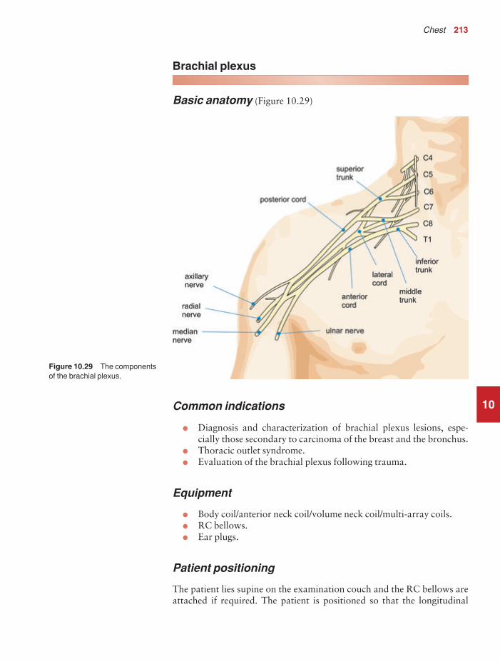
Chest 213
10
Brachial plexus
Basic anatomy (Figure 10.29)
Figure 10.29 The componentsof the brachial plexus.
Common indications
• Diagnosis and characterization of brachial plexus lesions, espe-cially those secondary to carcinoma of the breast and the bronchus.
• Thoracic outlet syndrome.• Evaluation of the brachial plexus following trauma.
Equipment
• Body coil/anterior neck coil/volume neck coil/multi-array coils.• RC bellows.• Ear plugs.
Patient positioning
The patient lies supine on the examination couch and the RC bellows areattached if required. The patient is positioned so that the longitudinal
9781405160858_4_010.qxd 28/05/2008 15:29 Page 213

214 Handbook of MRI Technique
10
alignment light lies in the midline, and the horizontal alignment lightpasses through the level of the sternoclavicular joints.
Suggested protocol
Axial SE/FSE T1
Acts as a localizer if three-plane localization is unavailable, or as a diagnostic sequence. Thick slices/gap are prescribed on either side of thehorizontal alignment light. The area from the sternoclavicular joints tothe third cervical vertebra is included in the image.
I 25 mm to S 25 mm
Coronal SE/FSE T1 (Figure 10.30)
Thin slices interleaved are prescribed from the posterior aspect of the cervical cord to the sternoclavicular joints. The area from the third cerv-ical vertebra to the aortic arch is included in the image.
Axial 3D incoherent (spoiled) GRE T1
Thin slices and a small or medium number of slice locations are prescribedfrom the arch of the aorta to the third cervical vertebra. Coverage may beextended to allow for slice wrap.
Axial SE/FSE PD/T2
Thin slices/gap are prescribed from the arch of the aorta to the third cer-vical vertebra. Chemical/spectral presaturation pulses are sometimes useful to differentiate tumour from fat.
Image optimization
Technical issues
The SNR and CNR characteristics of the brachial plexus are dependenton the type of coil used. Surface coils and specifically designed volumecoils return a higher signal than the body coil, and therefore improvedspatial resolution is obtained. SE provides optimum contrast, but FSE can be implemented if required. Spatial resolution is important as it is necessary to demonstrate the nerve pathways within the brachial plexus.The coronal series requires the thinnest slices possible with interleaving. A volume acquisition is also beneficial as very thin slices with no gap areacquired, along with visualization of anatomy in any plane. However, the scan times are quite lengthy, increasing the likelihood of patient
9781405160858_4_010.qxd 28/05/2008 15:29 Page 214

Chest 215
10movement. As the purpose of the volume acquisition is to demonstrateanatomy, an incoherent (spoiled) GRE T1 is the pulse sequence of choice.
Artefact problems
The main source of artefact is from respiratory motion, and therefore RCis used if this is especially troublesome. Alternatively breath-hold tech-niques may be utilized to suspend respiratory motion. Motion artefactoccurs in the phase direction, and therefore swapping the phase axis to S and I on the coronal series is often beneficial. As a fairly small FOV isselected to optimize spatial resolution, aliasing is a problem if the bodycoil is used. Oversampling is therefore necessary if anatomy lies within thecoil but outside the FOV in the phase direction.
Spatial presaturation pulses are important in the S to I direction toreduce flow in the carotid and jugular vessels. In addition, on the coronalseries, R and L spatial presaturation pulses decrease flow artefact from thesubclavian vessels. GMN also reduces flow artefact but, as it increases thesignal in vessels and the minimum TE, it is not usually beneficial in T1weighted sequences. There is always some slice wrap on the first and
Figure 10.30 Coronal SE T1weighted image of a normalbrachial plexus.
9781405160858_4_010.qxd 28/05/2008 15:29 Page 215

216 Handbook of MRI Technique
last slices of the volume acquisition. Spatial presaturation pulses placedover anatomy outside the volume, in the direction of slice acquisition,significantly reduce this. For example, in an axial volume acquisition, spatial presaturation pulses placed S and I to the imaging volume nullifysignal from slices that may wrap into the volume from above and below(see Volume imaging under Parameters and trade-offs in Part 1).
Patient considerations
Warn the patient of the length of the volume acquisition and the import-ance of keeping still. Due to excessively loud gradient noise associatedwith some sequences, ear plugs must always be provided to prevent hearing impairment.
Contrast usage
Contrast may be used to enhance masses in the brachial plexus but is notroutinely given.
10
9781405160858_4_010.qxd 28/05/2008 15:29 Page 216
11
11Liver and biliary system 219Kidneys and adrenal glands 226Pancreas 233Vascular imaging 239
Abdomen
217
9781405160858_4_011.qxd 28/05/2008 15:30 Page 217

218 Handbook of MRI Technique
11
Table 11.1 Summary of parameters. The figures given are general and should beadjusted according to the system used (Table 2.1)
Spin echo (SE)short TE min to 30 mslong TE 70 ms +short TR 300–600 mslong TR 2000 ms +
Fast spin echo (FSE)short TE min–20 mslong TE 90 ms +short TR 400–600 mslong TR 4000 ms +short ETL 2–6long ETL 16 +
Inversion recovery (IR) T1short TE min–20 mslong TR 3000 ms +medium TI 200–600 msshort ETL 2–6
STIRlong TE 60 ms +long TR 3000 ms +short TI 100–175 mslong ETL 12–20
FLAIRlong TE 60 ms +long TR 3000 ms +long TI 1700–2200 mslong ETL 12–20
Slice thickness2D thin 2–4 mm
medium 5–6 mmthick 8 mm
3D thin ≤ 1 mmthick ≥ 3 mm
FOVsmall ≤ 18 cmmedium 18–30 cmlarge ≥ 30 cm
NEX/NSAshort ≤ 1medium 2–3multiple ≥ 4
Coherent GRElong TE 15 ms +short TR ≤ 50 msflip angle 20°–40°
Incoherent GREshort TE min–5 msshort TR ≤ 50 msflip angle 20°–40°
Balanced GRETE minimumTR minimumflip angle ≥ 40°
SSFPTE minimumTR 40–50 msflip angle 20°–40°
Slice numbersVolumes small ≤ 32
medium 64large ≥ 128
Matrix (frequency ×× phase)coarse 256 × 128 or 256 × 192medium 256 × 256 or 512 × 256fine 512 × 512very fine ≥ 512 × 512
PC-MRA2D and 3D TE minimum
TR 25–33 msflip angle 30°
VENC venous 20–40 cm/sVENC arterial 60 cm/s
TOF-MRA2D TE minimum
TR 28–45 msflip angle 40°–60°
3D TE minimumTR 25–50 msflip angle 20°–30°
9781405160858_4_011.qxd 28/05/2008 15:30 Page 218

Abdomen 219
11
Liver and biliary system
Basic anatomy (Figure 11.1)
Figure 11.1 The componentsof the liver and biliary system.
Common indications
• Focal lesions and staging of neoplasms.• Benign hepatic disease, especially haemangioma and focal nodular
hyperplasia.• Haemochromatosis.• Gallbladder disease.• Biliary duct obstruction.• Evaluation of liver infiltrants such as iron or fat.
Equipment
• Body coil/volume torso array or multi-coil.• RC bellows.• Ear plugs.• Pe gating leads if required.
Patient positioning
The patient lies supine on the examination couch with the RC bellows (if required) securely attached. The patient is positioned so that the lon-gitudinal alignment light lies in the midline, and the horizontal alignment
9781405160858_4_011.qxd 28/05/2008 15:30 Page 219

220 Handbook of MRI Technique
11
light passes through the level of the third lumbar vertebra, or the lowercostal margin.
Suggested protocol
Coronal breath-hold incoherent (spoiled) GRE/SE T1 (Figure 11.2)
Acts as a localizer if three-plane localization is unavailable, or as a diag-nostic sequence. Thick slices/gap are prescribed relative to the verticalalignment light, from the posterior abdominal muscles to the anteriorabdominal wall. The area from the pubis symphysis to the diaphragm isincluded in the image.
P 60 mm to A 40 mm
Axial SE/FSE/incoherent (spoiled) GRE T1 +/− in and out of phase(Figures 11.3 and 11.4)
As for Coronal T1, except prescribe slices from the inferior margin of theliver to the diaphragm.
Figure 11.2 Coronal SE T1weighted image through theabdomen demonstrating sliceprescription boundaries andorientation for axial imaging of the liver.
9781405160858_4_011.qxd 28/05/2008 15:30 Page 220

11
Figure 11.3 Axial FSE T1weighted image through the liver.
Figure 11.4 Axial incoherent(spoiled) T1 weighted breath-hold image of the liver.
9781405160858_4_011.qxd 28/05/2008 15:30 Page 221

222 Handbook of MRI Technique
11
Delayed scans after contrast enhancement using chemical/spectral presaturation techniques are sometimes necessary to evaluate arterial andvenous phases.
Axial SE/FSE T2 or GRE T2* (Figures 11.5 and 11.6)
Slice prescription as for Axial T1.
Axial SE/FSE/breath-hold incoherent (spoiled) GRE T1 + contrast
Slice prescription as for Axial T1.
Additional sequences
SS-FSE (MRCP) (Figure 11.7)
This sequence provides images in which only fluid-filled spaces such as thegall bladder and biliary ducts return signal. It is necessary to use very longTEs and TRs to effectively nullify the signal from all tissues except thosethat have long T2 decay times. TEs in excess of 200 ms and TRs of morethan 10 s are required (see also Pancreas and Salivary glands). If SS-FSE isunavailable then an FSE sequence may be substituted.
Figure 11.5 Axial fast GRET2* through the liver.
9781405160858_4_011.qxd 28/05/2008 15:30 Page 222

11
Figure 11.6 Axial SS-FSE T2through the liver.
Figure 11.7 Coronal SS-FSEimage of the gallbladder(MRCP). Very long values of TR and TE were used toacquire images in which onlyfluid is seen.
9781405160858_4_011.qxd 28/05/2008 15:30 Page 223

224 Handbook of MRI Technique
SS-FSE/GRE-EPI/SE-EPI/diffusion imaging
The use of real-time imaging has applications in the liver and biliary sys-tem. This includes biopsies and thermal ablations of liver lesions underreal-time MR control. In addition, diffusion and perfusion techniques ofthe liver have been developed that may negate the use of contrast agents in the future. DWI images are overlaid onto T1 weighted acquisitions.The DWI image set provides pathology information, whereas the T1weighted acquisition provides anatomical data. The images produced arenot dissimilar to a PET/CT scan. In addition diffusion tensor imagingused in conjunction with parallel imaging techniques enables differenti-ation of benign from malignant hepatic lesions and may also assist in thequantification of hepatic fibrosis.
Image optimization
Technical issues
The inherent SNR and CNR of the abdominal contents are usually excellent due to their high proton density, and the use of a torso array coilincreases this even further. In addition parallel imaging techniques usingmulti-array coils reduce scan time significantly. Due to respiratory artefact, RC or respiratory triggering may be necessary. Alternatively, breath-holdtechniques may be used to suspend respiratory motion. In axial T1sequences, it is necessary to shorten the TR to less than 400 ms in SEsequences as this is considered the optimum value for demonstrating livercontrast. As the slice number available per acquisition is reduced with ashort TR, two or three acquisitions may be required to cover the wholeliver. Two FSE sequences using TEs of 80 ms and 160 ms are required tocharacterize haemangiomas, which retain a high signal intensity on lateecho images.
Artefact problems
The main source of artefact in the liver is motion caused by respiration,flow and peristalsis. RC or respiratory triggering is often required, especi-ally on the superior axial slices, due to the proximity of the diaphragm.However, breath-hold techniques may also be utilized. Pe gating is some-times used but it often increases the scan time, especially if the patient’sheart rate is slow or cardiac output poor, so that the system cannot triggerefficiently off each R wave. Commonly, Pe gating does not significantlyincrease image quality and only serves to lengthen the scan time. Underthese circumstances it is advisable to dispense with it. Spatial presatura-tion pulses placed S and I to the FOV are necessary to decrease flowmotion artefact in the aorta and IVC. GMN also minimizes flow artefactbut, as it increases the signal in vessels and the minimum TE, it is not usu-ally beneficial in T1 weighted sequences. Bowel motion is often a problemon the lower axial slices of the liver, whereas gastric motion artefact
11
9781405160858_4_011.qxd 28/05/2008 15:30 Page 224

Abdomen 225
11
is sometimes evident on the more superior slices. Antispasmodic agents,given IV, IM or subcutaneously prior to the examination, effectivelyreduce this.
Patient considerations
Careful explanation of the procedure is important. Ensure that the patientis as comfortable as possible. Some antispasmodic agents given IM maycause nausea but fruit juice given after the study can alleviate this.
Due to excessively loud gradient noise associated with some sequences,ear plugs must always be provided to prevent hearing impairment.
Contrast usage
Contrast is often beneficial to demonstrate liver metastases. Weightingdepends on the type of contrast media used. T1 shortening agents such as gadolinium require T1 weighted post-contrast scans. These can beacquired in conjunction with chemical/spectral presaturation pulses andacquired in multiple phases to evaluate the dynamic contrast enhance-ment characteristics of hepatic lesions. T2 weighting is necessary afterinjection of superparamagnetic T2 shortening (liver specific) agents (seeContrast agents in Part 1). Scans should be delayed for approximately 1 hour after injection to allow time for uptake of contrast by the liver. Theuse of contrast and dynamic imaging to visualize liver vasculature and the biliary system is gaining in popularity. Oral and rectal contrast agents,for evaluation of gastrointestinal disease, are also used (see Contrastagents in Part 1).
9781405160858_4_011.qxd 28/05/2008 15:30 Page 225

226 Handbook of MRI Technique
11
Kidneys and adrenal glands
Basic anatomy (Figure 11.8)
Figure 11.8 The urinarysystem and its vascular supply.
Common indications
• Adrenal masses and haemorrhage.• Renal masses and haemorrhage.• Renal cell carcinoma.• Renal transplant rejection.• Ureteric obstruction.
Equipment
• Body coil/multi-phased array or multi-coil array.• RC bellows.• Ear plugs.
9781405160858_4_011.qxd 28/05/2008 15:31 Page 226

Abdomen 227
11
Patient positioning
The patient lies supine on the examination couch with the RC bellowssecurely attached (if required). The patient is positioned so that the longit-udinal alignment light lies in the midline, and the horizontal alignmentlight passes through the level of the third lumbar vertebra, or the lowercostal margin. The kidneys are generally located about four fingers infe-rior to the xiphoid.
Suggested protocol
Coronal breath-hold fast incoherent (spoiled) GRE/SE/FSE T1 (Figure 11.9)
Acts as a localizer if three-plane localization is unavailable. Alternativelyit can be used as a diagnostic sequence. Medium slices/gap are prescribedon either side of the vertical alignment light, from the posterior abdominal
Figure 11.9 Coronalincoherent (spoiled) GRE T1weighted image through theabdomen demonstrating thekidneys.
9781405160858_4_011.qxd 28/05/2008 15:31 Page 227

228 Handbook of MRI Technique
11
muscles to the anterior abdominal wall. The area from the pubis sym-physis to the diaphragm is included in the image.
P 60 mm to A 40 mm
Axial incoherent (spoiled) GRE T1 in and out of phase +/− contrast +/− chemical/spectral presaturation (Figures 11.11, 11.13 and 11.14)
As for Coronal SE/FSE T1, except medium slices/gap are prescribed fromthe inferior margin of the kidneys to the superior aspect of the adrenals(Figure 11.10). The coronal plane may also be useful depending on lesionlocation. Slices may also be offset to specifically image the adrenals(Figure 11.12).
Additional sequences
MR urography
Either FSE or SS-FSE sequences may be used with very long TEs and TRsto produce heavily T2 weighted images in which only fluid that has a very
Figure 11.10 Coronalincoherent (spoiled) GRE T1weighted through the abdomendemonstrating slice prescriptionboundaries and orientation foraxial imaging of the kidneys.
9781405160858_4_011.qxd 28/05/2008 15:31 Page 228

11
Figure 11.11 Axial incoherent(spoiled) GRE T1 weightedimage acquired with a TE whenfat and water are in phase(above) and out of phase(below).
Figure 11.12 Coronalincoherent (spoiled) GRE T1weighted through the abdomendemonstrating slice prescriptionboundaries and orientation foraxial imaging of the adrenals.
9781405160858_4_011.qxd 28/05/2008 15:31 Page 229

11
Figure 11.13 Axial fastincoherent (spoiled) GRE T1weighted image through thekidneys.
Figure 11.14 Axial incoherent(spoiled) GRE T1 with chemical/spectral presaturation.
9781405160858_4_011.qxd 28/05/2008 15:31 Page 230

Abdomen 231
long T2 decay time is seen. It has applications in the biliary system (seealso Liver and biliary system earlier in this chapter) and in the salivarygland. It may also be of use in the urinary system to visualize the renal collecting system, the ureters and the bladder.
Diffusion imaging
DWI using SS-EPI acquisition in conjunction with parallel imaging tech-niques may be useful in the differentiation of malignant adrenal lesionsfrom hyperplasia or adenomas and renal cysts from renal cell carcinomas.
Image optimization
Technical issues
The inherent SNR and CNR of the abdominal contents are usually excel-lent due to their high proton density, and the use of a torso array coilincreases this even further. In addition, parallel imaging techniques usingmulti-array coils reduce scan times significantly. Spatial resolution isimportant, especially when imaging relatively small structures such as the kidneys and adrenal glands, which therefore require thin slices/gap.However, this is often difficult to achieve when using the body coil, a largeFOV and in the presence of respiratory and flow artefact. The use of atorso array coil greatly improves resolution in the abdomen. In addition,parallel imaging techniques can be used to improve resolution whilstkeeping scan times short. SE sequences usually produce the best contrastin the abdomen, but result in fairly lengthy scan times. For this reason,breath-hold GRE or SS-FSE sequences are often preferred. FSE used inconjunction with a rectangular/asymmetric FOV allows PD and T2 imagesto be obtained in a shorter scan time.
Artefact problems
The main source of artefact in this area is from respiratory movement and flow in the aorta and the IVC. RC or respiratory triggering is oftenrequired and significantly reduces respiratory ghosting. Alternatively,breath-hold techniques may be utilized. Spatial presaturation pulses placedS and I to the FOV are necessary to reduce flow motion artefact arisingfrom the aorta and IVC. As the kidneys and adrenals are retroperitonealstructures, a spatial presaturation band brought into the FOV and placedover the anterior abdominal wall reduces respiratory artefact significantlywithout obscuring important anatomy. GMN also minimizes flow and, in some cases, respiratory motion but it increases the signal in vessels andthe minimum TE.
Chemical shift artefact is often troublesome in the kidneys, especially athigher field strengths. This is due to retroperitoneal fat being adjacent to fluid-filled kidneys. Narrowing the receive bandwidth increases this
11
9781405160858_4_011.qxd 28/05/2008 15:31 Page 231

232 Handbook of MRI Technique
11
artefact but, if used in conjunction with fat suppression techniques,results in a significant improvement in SNR and a reduction in chemicalshift. However, this strategy increases the minimum TE and is thereforereserved for T2 weighted sequences. Bowel motion is also troublesomebut is effectively reduced by the administration of antispasmodic agentsgiven IV, IM or subcutaneously prior to the examination.
Patient considerations
Careful explanation of the procedure is important. Ensure that the patientis as comfortable as possible. Some antispasmodic agents given IM maycause nausea but fruit juice given after the study can alleviate this. Due toexcessively loud gradient noise associated with some sequences, ear plugsmust always be provided to prevent hearing impairment.
Contrast usage
Contrast is sometimes useful in conjunction with dynamic imaging tovisualize the uptake of contrast in the kidneys (see Dynamic imagingunder Pulse sequences in Part 1). Vascular imaging of the renal arteries isa common technique discussed later (see Vascular imaging later in thischapter). Contrast may also be necessary to increase the conspicuity of the adrenal glands. Recently functional imaging of the kidneys after theadministration of macro molecular contrast agents have been advocatedin the evaluation of a variety of renal diseases. These agents are almosttotally excreted by the kidneys, thereby improving the conspicuity of lesionsthat have different perfusion characteristics.
9781405160858_4_011.qxd 28/05/2008 15:31 Page 232

Abdomen 233
11
Pancreas
Basic anatomy (Figure 11.15)
Figure 11.15 The pancreas.
Common indications
• Pancreatic tumours.• Pancreatic duct obstruction.
Equipment
• Body coil/multi-phased array/multi-array coil.• RC bellows.• Ear plugs.
Patient positioning
The patient lies supine on the examination couch with the RC bellowssecurely attached. The patient is positioned so that the longitudinal align-ment light lies in the midline, and the horizontal alignment light passesthrough the level of the third lumbar vertebra, or the lower costal margin.
Suggested protocol
Coronal breath-hold fast incoherent (spoiled) GRE/SE T1 (see Figure 11.9)
Acts as a localizer if three-plane localization is unavailable, or as a diagnostic sequence. Thick slices/gap are prescribed on either side of the
9781405160858_4_011.qxd 28/05/2008 15:31 Page 233

234 Handbook of MRI Technique
11
vertical alignment light, from the posterior abdominal muscles to theanterior abdominal wall. The area from the pubis symphysis to thediaphragm is included in the image.
P 60 mm to A 40 mm
Axial FSE/SE/breath-hold fast incoherent (spoiled) GRE T1 +/− chemical/spectral presaturation/in and out of phase imaging
As for Coronal T1, except thin slices/gap are prescribed through the pan-creas (Figure 11.16).
Axial FSE/SS-FSE T2 (Figures 11.17 and 11.18)
Slice prescription as for Axial T1.
Axial breath-hold fast incoherent (spoiled) GRE T1 (Figure 11.19)
For visualization of small pancreatic tumours +/− contrast.
Figure 11.16 Coronal FSE T1weighted image through theabdomen demonstrating sliceprescription boundaries andorientation for axial imaging ofthe pancreas.
9781405160858_4_011.qxd 28/05/2008 15:31 Page 234

11
Figure 11.17 Axial highresolution FSE T2 of thepancreas.
Figure 11.18 Axial SS-FSE T2of the pancreas during freebreathing.
9781405160858_4_011.qxd 28/05/2008 15:31 Page 235
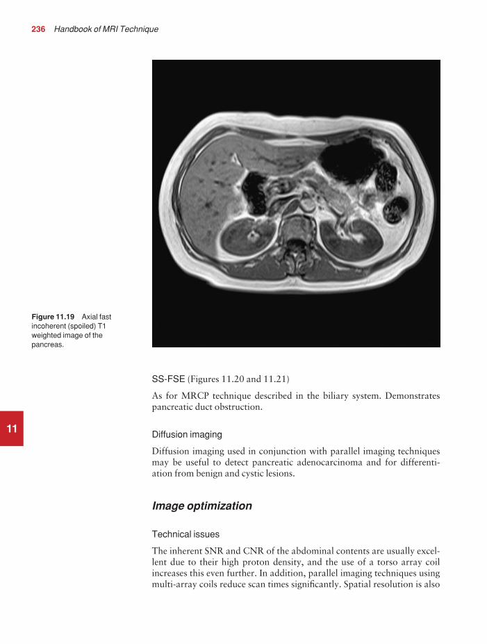
236 Handbook of MRI Technique
11
SS-FSE (Figures 11.20 and 11.21)
As for MRCP technique described in the biliary system. Demonstratespancreatic duct obstruction.
Diffusion imaging
Diffusion imaging used in conjunction with parallel imaging techniquesmay be useful to detect pancreatic adenocarcinoma and for differenti-ation from benign and cystic lesions.
Image optimization
Technical issues
The inherent SNR and CNR of the abdominal contents are usually excel-lent due to their high proton density, and the use of a torso array coilincreases this even further. In addition, parallel imaging techniques usingmulti-array coils reduce scan times significantly. Spatial resolution is also
Figure 11.19 Axial fastincoherent (spoiled) T1weighted image of thepancreas.
9781405160858_4_011.qxd 28/05/2008 15:31 Page 236

11
Figure 11.20 MRCP of thepancreatic duct.
Figure 11.21 MRCP of thepancreatic duct and the rest ofthe biliary system.
9781405160858_4_011.qxd 28/05/2008 15:31 Page 237
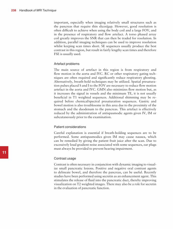
238 Handbook of MRI Technique
11
important, especially when imaging relatively small structures such as the pancreas that require thin slices/gap. However, good resolution isoften difficult to achieve when using the body coil and a large FOV, and in the presence of respiratory and flow artefact. A torso phased array coil greatly improves the SNR that can then be traded for resolution. Inaddition, parallel imaging techniques can be used to improve resolutionwhilst keeping scan times short. SE sequences usually produce the bestcontrast in this region, but result in fairly lengthy scan times and thereforeFSE is usually used.
Artefact problems
The main source of artefact in this region is from respiratory and flow motion in the aorta and IVC. RC or other respiratory gating tech-niques are often required and significantly reduce respiratory ghosting.Alternatively, breath-hold techniques may be utilized. Spatial presatura-tion pulses placed S and I to the FOV are necessary to reduce flow motionartefact in the aorta and IVC. GMN also minimizes flow motion but, as it increases the signal in vessels and the minimum TE, it is not usuallybeneficial in T1 weighted sequences. Additional shimming may be re-quired before chemical/spectral presaturation sequences. Gastric andbowel motion is also troublesome in this area due to the proximity of thestomach and the duodenum to the pancreas. This artefact is effectivelyreduced by the administration of antispasmodic agents given IV, IM orsubcutaneously prior to the examination.
Patient considerations
Careful explanation is essential if breath-holding sequences are to be performed. Some antispasmodics given IM may cause nausea, which can be remedied by giving the patient fruit juice after the scan. Due toexcessively loud gradient noise associated with some sequences, ear plugsmust always be provided to prevent hearing impairment.
Contrast usage
Contrast is often necessary in conjunction with dynamic imaging to visual-ize small pancreatic lesions. Positive and negative oral contrast agents to delineate bowel, and therefore the pancreas, can be useful. Recentlystudies have been performed using secretin as an enhancement agent. Thisstimulates the release of fluid into the pancreatic duct, thereby improvingvisualization on T2 weighted images. There may also be a role for secretinin the evaluation of pancreatic function.
9781405160858_4_011.qxd 28/05/2008 15:31 Page 238

Abdomen 239
11
Vascular imaging
Basic anatomy (Figure 11.22)
Figure 11.22 Anterior view ofthe abdomen showing arterialvessels.
Common indications
• Pre-operative assessment of aortic thrombus, occlusion, stenosis anddissection.
• Demonstration of major vascular anomalies.• Portal or hepatic vein thrombosis.• Evaluation of hepatic vascular anatomy prior to tumour resection.• Renal vein thrombosis.• Assessment of vasculature prior to and after renal transplantation.
Equipment
• Body coil/volume torso array/multi-array coil.• Ear plugs.
Patient positioning
The patient lies supine on the examination couch and is positioned so that the longitudinal alignment light lies in the midline, and the horizontal
9781405160858_4_011.qxd 28/05/2008 15:31 Page 239

240 Handbook of MRI Technique
alignment light passes through the level of the third lumbar vertebra, orthe lower costal margin.
For localized imaging, the horizontal alignment light passes throughthe vessel to be imaged.
Suggested protocol
MRA is now a well established technique but has its limitations. Coronalor sagittal breath-hold incoherent (spoiled) GRE localizers may be fol-lowed by axial 2D or 3D TOF-MRA that are then reconstructed in a number of planes. Although 2D TOF-MRA provides coverage, Venetianblind artefact and poor resolution reduce image quality. 3D TOF-MRAprovides better resolution but less coverage (see Pulse sequences in Part 1). Therefore, alternative methods of visualizing abdominal vascularanatomy such as breath-hold incoherent (spoiled) GRE T1 imaging before,during, and after administration of a bolus of contrast and SE black bloodand GRE bright blood sequences are important.
CE-MRA of the abdominal aorta and renal arteries is a well establishedtechnique. A small bolus of gadolinium is given via cannula in the antecu-bital fossa, the acquisition timed to the arrival of the bolus in the area ofinterest (see Dynamic imaging in Part 1). Fast incoherent (spoiled) GRE isthe sequence of choice and the coronal plane is used (Figure 11.23).
When used in conjunction with SE sequences, spatial presaturationpulses produce black blood. If a signal persists in a vessel it may indicateeither slow flow or occlusion. When used in conjunction with GREsequences, GMN produces bright blood. If a signal void is seen within thevessel, it may indicate either slow flow or occlusion.
Image optimization
Technical issues
The SNR and CNR in vascular imaging of the abdomen are improved bythe use of phased array coils. In addition parallel imaging techniques allowfor reduced scan times or improved resolution. However, when contrastenhancement is used images can be acquired rapidly at the expense of SNRand CNR, as gadolinium provides enough contrast to visualize vesselstructure. Additional options such as centric K space filling or propellerimaging (where K space is filled in rotating strips) permit improved temporal resolution when the contrast agent is in the imaging volume.
If conventional MRA is used, to optimize vessel contrast on TOF-MRAsequences, spatial presaturation bands are placed S to the FOV to visualizethe IVC, and I to the FOV to demonstrate the aorta. Vessel conspicuity isincreased by the implementation of GMN, which increases signal in ves-sels, and MT, which suppresses background signal (see Pulse sequences inPart 1).
11
9781405160858_4_011.qxd 28/05/2008 15:31 Page 240

Abdomen 241
11
Artefact problems
Respiratory motion is a potential source of artefact in these examinations.Venetian blind artefact, commonly seen in 2D TOF-MRA sequences, isalso caused by respiration and pulsatile flow (see Vascular imaging in Part 1). The implementation of breath-hold techniques is often, therefore,necessary. Gated TOF-MRA and the utilization of travelling presatura-tion bands may be implemented to reduce pulsatile artefacts.
Patient considerations
Due to excessively loud gradient noise associated with some sequences,ear plugs must always be provided to prevent hearing impairment.
Contrast usage
The use of MRA, in conjunction with contrast enhancement to improveimage quality, is an important technique. Enhancing agents shorten theT1 of blood, thereby increasing vessel contrast in sequences that are sensitive to T1. In addition, agents that remain in the blood for delayed
Figure 11.23 Coronal breath-hold incoherent (spoiled) GRET1 weighted image duringdynamic contrast enhancement.
9781405160858_4_011.qxd 28/05/2008 15:32 Page 241

242 Handbook of MRI Technique
vascular imaging (blood pool agents) are sometimes used. For contrastenhanced MRA studies, early acquisitions demonstrate the arterial phase,mid-term acquisitions the capillary phase, and later acquisitions thevenous phase. Therefore timing of each acquisition after injection isimportant. This is usually automated by the system where data acquisi-tion is triggered by an increase in signal detected by a navigator as thegadolinium arrives in the aorta.
11
9781405160858_4_011.qxd 28/05/2008 15:32 Page 242

12
12Male pelvis 245Female pelvis 253Obstetrics 258
Pelvis
243
9781405160858_4_012.qxd 28/05/2008 15:34 Page 243

244 Handbook of MRI Technique
12
Table 12.1 Summary of parameters. The figures given are general and should beadjusted according to the system used (Table 2.1)
Spin echo (SE)short TE min to 30 mslong TE 70 ms +short TR 300–600 mslong TR 2000 ms +
Fast spin echo (FSE)short TE min–20 mslong TE 90 ms +short TR 400–600 mslong TR 4000 ms +short ETL 2–6long ETL 16 +
Inversion recovery (IR) T1short TE min–20 mslong TR 3000 ms +medium TI 200–600 msshort ETL 2–6
STIRlong TE 60 ms +long TR 3000 ms +short TI 100–175 mslong ETL 12–20
FLAIRlong TE 60 ms +long TR 3000 ms +long TI 1700–2200 mslong ETL 12–20
Slice thickness2D thin 2–4 mm
medium 5–6 mmthick 8 mm
3D thin ≤ 1 mmthick ≥ 3 mm
FOVsmall ≤ 18 cmmedium 18–30 cmlarge ≥ 30 cm
NEX/NSAshort ≤ 1medium 2–3multiple ≥ 4
Coherent GRElong TE 15 ms +short TR ≤ 50 msflip angle 20°–40°
Incoherent GREshort TE min–5 msshort TR ≤ 50 msflip angle 20°–40°
Balanced GRETE minimumTR minimumflip angle ≥ 40°
SSFPTE minimumTR 40–50 msflip angle 20°–40°
Slice numbersVolumes small ≤ 32
medium 64large ≥ 128
Matrix (frequency ×× phase)coarse 256 × 128 or 256 × 192medium 256 × 256 or 512 × 256fine 512 × 512very fine ≥ 512 × 512
PC-MRA2D and 3D TE minimum
TR 25–33 msflip angle 30°
VENC venous 20–40 cm/sVENC arterial 60 cm/s
TOF-MRA2D TE minimum
TR 28–45 msflip angle 40°–60°
3D TE minimumTR 25–50 msflip angle 20°–30°
9781405160858_4_012.qxd 28/05/2008 15:34 Page 244

Pelvis 245
12
Male pelvis
Basic anatomy (Figure 12.1)
Figure 12.1 Sagittal sectionthrough the male pelvis showingmidline structures.
Common indications
• Localization of undescended testicles.• Prostatic lesions.• Carcinoma of the bladder.• Rectal lesions.• Infertility.• Impotence.
Equipment
• Body coil/phased array pelvic coil/multi-array coil. Local rectal coilfor prostate imaging (can be used in conjunction with a phased/multi-array coil).
• Compression bands and foam immobilization pads.• Ear plugs.
Patient positioning
The patient lies supine on the examination couch. Foam pads and com-pression bands can be applied across the patient’s lower pelvis to reduce
9781405160858_4_012.qxd 28/05/2008 15:35 Page 245

246 Handbook of MRI Technique
12
respiratory and bowel motion (unless the patient cannot tolerate this).The patient is positioned so that the longitudinal alignment light lies in themidline, and the horizontal alignment light passes through a point mid-way between the pubis symphysis and the iliac crests. If a local rectal coilis used, it should be carefully inserted prior to the examination. Ensurethat it is correctly positioned and fully inflated.
Suggested protocol
Coronal breath-hold fast incoherent (spoiled) GRE/SE/FSE T1 (Figure 12.2)
Acts as a localizer if three-plane localization is unavailable, or as a diag-nostic sequence. Thick slices/gap are prescribed from the coccyx to theanterior aspect of the pubis symphysis. The area from the pubis symphysisto the iliac crests is included in the image.
P 60 mm to A 60 mm
Figure 12.2 Coronal FSE T1weighted image through themale pelvis.
9781405160858_4_012.qxd 28/05/2008 15:35 Page 246

Pelvis 247
12
Sagittal localizers used in conjunction with a large FOV are useful toconfirm the correct positioning of a rectal coil and to demonstrate nodesand bony metastases in patients with suspected prostatic carcinoma.
L 25 mm to R 25 mm
Sagittal SE/FSE T2
Demonstrates organs that lie in the midline (bladder, rectum, prostate,penis). Medium or thick slices/gap are prescribed from the left to the right pelvic side walls (Figure 12.3). Unless lymph node involvement issuspected, small structures such as the prostate require high-resolutionimaging using the rectal coil and thin slices/gap prescribed through theROI only. Chemical/spectral presaturation pulses are often necessarywhen using FSE sequences.
Axial SE/FSE T2 (Figure 12.5)
Demonstrates organs that lie laterally (lymph nodes). Medium or thickslices/gap are prescribed from the pelvic floor to the iliac crests (Figure12.4). Unless lymph node involvement is suspected, small structures such
Figure 12.3 Coronal FSE T1weighted image through themale pelvis to show sliceprescription boundaries andorientation for sagittal imaging.
9781405160858_4_012.qxd 28/05/2008 15:35 Page 247

12
Figure 12.4 Coronal FSE T1weighted image through themale pelvis to show sliceprescription boundaries andorientation for axial imaging.
Figure 12.5 Axial FSE T2weighted image through a normal male pelvis (rectal coil in situ).
9781405160858_4_012.qxd 28/05/2008 15:35 Page 248

Pelvis 249
12
as the prostate require high-resolution imaging using the rectal coil andthin slices/gap prescribed through the ROI only. Chemical/spectral pre-saturation pulses are often necessary when using FSE sequences.
Axial SE/FSE T1 (Figure 12.6)
Slice prescription as for Axial T2.
Coronal SE/FSE T2 (Figure 12.7)
Slice prescription as for Coronal SE/FSE T1.Chemical/spectral presaturation pulses are often necessary when using
FSE sequences.
Additional sequences
Fast incoherent (spoiled) GRE T1 +/− contrast (Figure 12.8)
Rapid imaging after contrast allows dynamic evaluation of enhancingpelvic vessels responsible for potency (see Dynamic imaging under Pulsesequences in Part 1).
Figure 12.6 Axial FSE T1weighted image of a normalmale pelvis.
9781405160858_4_012.qxd 28/05/2008 15:35 Page 249

12
Figure 12.7 Coronal FSE T2weighted image demonstratingan abnormal prostrate gland.
Figure 12.8 Incoherent(spoiled) GRE T1 of the prostateusing a rectal coil.
9781405160858_4_012.qxd 28/05/2008 15:35 Page 250

Pelvis 251
12
SS-FSE/SE-EPI/GRE-EPI/Diffusion Imaging
Real-time imaging of pelvic organs, especially the prostate, enables biopsiesand laser ablations of lesions under MR control. DWI used in conjunctionwith parallel imaging techniques are proving useful in the differentiationof malignant from benign lesions especially in the prostate gland. In addi-tion, small FOV high resolution images of the scrotum may be useful forthe evaluation of testicular carcinoma (Figure 12.9).
Image optimization
Technical issues
The pelvis offers excellent SNR and contrast, especially when phasedarray, multi-array or local rectal coils are used. As a result, spatial resolu-tion is easily obtainable without compromising signal. In addition the use of parallel imaging techniques can significantly reduce scan times orincrease resolution. FSE provides very good results in the pelvis, as re-spiration and bowel motion are less troublesome than in the abdomen. In addition, a rectangular/asymmetric FOV is routinely implemented withthe long axis of the rectangle S to I in the sagittal images, and R to L in the
Figure 12.9 Axial FSE T2weighted image of the scrotumacquired with a surface coil.This was performed for theevaluation of testicularcarcinoma.
9781405160858_4_012.qxd 28/05/2008 15:35 Page 251

252 Handbook of MRI Technique
axials. The combination of FSE, a rectangular/asymmetric FOV, and localor phased array or multi-array coils (where a small FOV is implemented)enables the acquisition of very fine matrix sizes in conjunction with ashort scan time.
Oversampling is sometimes not available with a rectangular/asymmetricFOV. If so, ensure that the FOV is large enough to incorporate all thepelvis, or apply spatial presaturation bands A and P to reduce aliasing. IfSE is selected, a fine matrix may still be utilized to provide good spatialresolution and a fairly short scan time. Fat suppression techniques areoften beneficial, especially on FSE T2 images.
Artefact problems
Bowel motion is reduced by compression and administering antispas-modic agents IV, IM or subcutaneously prior to the examination. Com-pression also reduces respiratory motion by encouraging the patient tobreathe from their upper abdomen and chest, rather than their pelvis.Spatial presaturation pulses applied S and I to the FOV reduce flowmotion artefact in the IVC, aorta and iliac vessels. GMN further reducesflow artefact but, as it increases signal in vessels and the minimum TE, it isnot usually beneficial in T1 weighted sequences. Additional shimmingmay be required before chemical/spectral presaturation sequences.
When imaging with a local rectal coil, rectal spasm commonly causesartefact. The phase and frequency axes are swapped on the sagittal and axial images so that this artefact does not obscure the prostate. Inaddition, oversampling is often necessary on these small FOV images, asanatomy exists outside the FOV in the phase direction, but within the signal-producing volume of the coil.
Patient considerations
Some patients may not be able to tolerate compression, especially if they have had recent abdominal surgery. Compression can also make aclaustrophobic patient feel more trapped. Under these circumstances,placing the patient prone has the same (albeit lesser) effect as compres-sion. In addition, if the ROI lies posteriorly (e.g. fistulae in the buttocks),placing the patient prone positions the ROI nearer to magnetic isocentre,thereby increasing image quality. Some antispasmodic agents given IMmay cause nausea but fruit juice given after the study can alleviate this.Due to excessively loud gradient noise associated with some sequences,ear plugs must always be provided to prevent hearing impairment.
Contrast usage
Contrast may be given to enhance the conspicuity of certain lesions, espe-cially in examinations of the prostate, pelvis masses and vasculature. Oralor rectal contrast agents including air (administered carefully) to label anddemonstrate the rectum and lower gastrointestinal tract are sometimes used.
12
9781405160858_4_012.qxd 28/05/2008 15:35 Page 252

Pelvis 253
12
Female pelvis
Basic anatomy (Figure 12.10)
Figure 12.10 Sagittal sectionthrough the female pelvisshowing midline structures.
Common indications
• Assessment of congenital abnormalities of the urogenital tract.• Cervical lesions.• Uterine lesions.• Benign uterine tumours, e.g. leiomyoma and fibroids.• Bladder lesions.• Rectal lesions.• Infertility.
Equipment
• Body coil/phased array pelvic coil/multi-array coil.• Compression bands and foam immobilization pads if using the
body coil.• Ear plugs.
Patient positioning
The patient lies supine on the examination couch. Foam pads and com-pression bands can be applied across the patient’s lower pelvis to reducerespiratory and bowel motion (unless the patient cannot tolerate this).
9781405160858_4_012.qxd 28/05/2008 15:35 Page 253

254 Handbook of MRI Technique
The patient is positioned so that the longitudinal alignment light lies in the midline, and the horizontal alignment light passes through a pointmidway between the pubis symphysis and the iliac crest. If a local rectalcoil is used, it should be carefully inserted prior to the examination.Ensure that it is correctly positioned and fully inflated.
Suggested protocol
Coronal breath-hold fast incoherent (spoiled) GRE/SE/FSE T1
Acts as a localizer if three-plane localization is unavailable, or as a diag-nostic sequence. Thick slices/gap are prescribed from the coccyx to theanterior aspect of the pubis symphysis. The area from the pubis symphysisto the iliac crests is included in the image.
P 60 mm to A 60 mm
Sagittal localizers are useful to confirm the correct positioning of a rectalcoil and to evaluate the uterus.
L 25 mm to R 25 mm
Sagittal SE/FSE T2 (Figures 12.11 and 12.12)
Demonstrates organs that lie in the midline (bladder, uterus, rectum,cervix). Medium or thick slices/gap are prescribed from the left to theright pelvic side walls (see Figure 12.3). Unless lymph node involvement issuspected, small structures such as the cervix require high-resolutionimaging using the rectal coil and thin slices/gap prescribed through theROI only. Chemical/spectral presaturation pulses are often necessarywhen using FSE sequences.
Axial SE/FSE T2
Demonstrates organs that lie laterally (ovaries, lymph, nodes). Mediumor thick slices/gap are prescribed from the pelvic floor to the iliac crests(see Figure 12.4). Unless lymph node involvement is suspected, smallstructures such as the cervix require high-resolution imaging using therectal coil and thin slices/gap prescribed through the ROI only. Chemical/spectral presaturation pulses are often necessary when using FSE sequences.
Axial SE/FSE T1
Slice prescription as for Axial T2.
Coronal SE/FSE T2
Slice prescription as for Coronal SE/FSE T1.Chemical/spectral presaturation pulses are often necessary when using
FSE sequences.
12
9781405160858_4_012.qxd 28/05/2008 15:35 Page 254

12
Figure 12.11 Sagittal FSE T2 weighted image through afemale pelvis.
Figure 12.12 Sagittal FSE T2weighted image demonstratinga large mass in the cervix. In thiscase the lesion has obstructedthe endometrial cavity, causingdistension.
9781405160858_4_012.qxd 28/05/2008 15:35 Page 255

256 Handbook of MRI Technique
12
Additional sequences
SS-FSE/GRE-EPI/SE-EPI/diffusion imaging
Real-time imaging enables biopsies and laser ablations of lesions underMR control. In additional cine imaging of the uterus is useful to evaluateuterine contractility in a variety of disorders. In addition this techniquemay be used to evaluate the pelvic floor. DWI, which may be used in conjunction with parallel imaging techniques, may be used to differen-tiate malignant from benign lesions and to evaluate tumour response totherapy.
Image optimization
Technical issues
The pelvis offers excellent SNR and contrast, especially when phasedarray, multi-array or local rectal coils are used. As a result, spatial resolu-tion is easily obtainable without compromising signal. In addition the use of parallel imaging techniques can significantly reduce scan times or increase resolution. FSE provides very good results in the pelvis, as respiration and bowel motion are less troublesome than in the abdomen.In addition, a rectangular/asymmetric FOV is routinely implemented withthe long axis of the rectangle S to I in the sagittal images, and R to L in theaxials. The combination of FSE, a rectangular/asymmetric FOV, and localor phased array coils (where a small FOV is implemented) enables theacquisition of very fine matrix sizes in conjunction with a short scan time.T2 weighting is optimal for evaluating the structure of the uterus.
On some systems, oversampling is not available with a rectangular/asymmetric FOV. If so, ensure that the FOV is large enough to incor-porate all the pelvis, or apply spatial presaturation bands A and P toreduce aliasing. If SE is selected, a fine matrix may still be utilized to provide good spatial resolution and a fairly short scan time. Fat suppres-sion techniques are often beneficial especially on FSE T2 images where fat and pathology return a similar signal.
Artefact problems
Bowel motion is reduced by compression and administering antispasmodicagents IV, IM or subcutaneously prior to the examination. Compressionalso reduces respiratory motion by encouraging the patient to breathefrom their upper abdomen and chest, rather than their pelvis. Spatial pre-saturation pulses applied S and I to the FOV reduce flow motion artefactin the IVC, aorta and iliac vessels. GMN further reduces flow artefact but,as it increases signal in vessels and the minimum TE, it is not usuallybeneficial in T1 weighted sequences. Additional shimming may be requiredbefore chemical/spectral presaturation sequences.
9781405160858_4_012.qxd 28/05/2008 15:35 Page 256

Pelvis 257
12
Patient considerations
Some patients may not be able to tolerate compression, especially if theyhave had recent abdominal surgery or have large lesions. Compressioncan also make a claustrophobic patient feel more trapped. Under thesecircumstances, placing the patient prone has the same (albeit lesser) effectas compression. In addition, if the ROI lies posteriorly (e.g. fistulae in the buttocks), placing the patient prone positions the ROI nearer to the magnetic isocentre, thereby increasing image quality. Some antispasmodicagents given IM may cause nausea, which can be alleviated by givingorange juice after the scan. Due to excessively loud gradient noise associ-ated with some sequences, ear plugs must always be provided to preventhearing impairment.
Contrast usage
Contrast may be given to enhance the conspicuity of certain lesions, especially in the cervix, uterus and ovaries. Dynamic imaging after con-trast administration may improve tumour localization and staging andalso help in monitoring response to therapy. Oral or rectal contrast agentsincluding air (administered carefully) to label and demonstrate the rectumand lower gastrointestinal tract are sometimes useful.
9781405160858_4_012.qxd 28/05/2008 15:35 Page 257

258 Handbook of MRI Technique
12
Obstetrics
Common indications
• Evaluation of pelvic–cephalic disproportion in the second or thirdtrimester of pregnancy, or post-delivery.
• Placenta praevia.• Evaluation of pelvic disease incidental to pregnancy and foetal
abnormalities (for foetal imaging see Paediatric imaging).
Equipment
• Body coil/multi-coil array.• (Compression bands if tolerable post partum.)• Ear plugs.
Patient positioning
The patient lies supine on the examination couch. The patient is posi-tioned so that the longitudinal alignment light lies in the midline, and thehorizontal alignment light passes through a point midway between thepubis symphysis and the iliac crest. Compression should not be applied in pregnancy or immediately post-Caesarean section.
Suggested protocol
Sagittal SE T1
Medium slices/gap are prescribed on either side of the longitudinal alignmentlight to include the pubis symphysis and the sacrum. System software canbe used to measure pelvic inlet and outlet dimensions.
L 15 mm to R 15 mm
Sagittal/Coronal/Axial SE/FSE/SS-FSE T1 and T2
As in standard protocol, for pelvic disease incidental to pregnancy and toevaluate foetal abnormalities.
Image optimization
Technical issues
MRI may be used to measure pelvic proportions, and to evaluate pelviclesions incidental to pregnancy. The purpose of MRI pelvimetry is to
9781405160858_4_012.qxd 28/05/2008 15:35 Page 258

Pelvis 259
12
visualize the bony landmarks of the sacrum and the pubis symphysis sothat accurate measurements can be made. Good SNR or spatial resolutionis, therefore, usually unnecessary and, as these patients may have to befitted into a busy schedule at short notice, scan time is the most importantfactor. If the coarsest matrix and lowest NEX/NSA are used, the aboveprotocol takes only 1 or 2 minutes to acquire.
If examining the pelvis for foetal abnormalities or incidental pelvic disease, good resolution may be difficult to achieve due to foetal move-ment. Sedation of the foetus by injection of drugs via the umbilical vein may be used to still the foetus if clinically justified. Alternatively, fast sequences such as SS-FSE may be utilized very effectively. A rectan-gular/asymmetric FOV improves resolution, although the bulk of theabdomen in the AP axis may cause aliasing. The implementation of FSEand chemical/spectral presaturation techniques are not recommended in pregnant patients due to the increased RF deposition of these options.At present, it is still unclear whether large quantities of RF are damagingto the foetus.
Artefact problems
Foetal and bowel motion may interfere with the image, but not usuallyenough to obscure the bony landmarks necessary for pelvimetry measure-ments. Spatial presaturation pulses placed S and I to the FOV reduce flow in the aorta and IVC. Take great care if placing presaturation bandsover the foetus as these increase the RF deposition within the infant.Minimizing the scan time is the best way of diminishing the effect of foetal movement in the image. Respiratory artefact is occasionally trou-blesome but RC is rarely necessary and breath-holding techniques canoften be used.
Patient considerations
In most countries MRI is as yet not indicated in the first trimester of pregnancy as the possible risks are unknown. However, in the second and third trimesters MRI is often preferred to CT or other imaging modal-ities that use ionizing radiation. In the US, the FDA (Food and DrugAdministration) approves the use of MR in all three trimesters if MRnegates the use of more invasive testing. In the later stages of pregnancy,the patient may feel faint when lying in the supine position from the babypressing on the IVC. Slightly raising one hip sometimes relieves this, but in pelvimetry studies it also complicates the calculation of the pelvic sizeas the patient is no longer truly sagittal. This is overcome by obliquing thesagittals from a localizer, but this lengthens the scan time due to the extrasequences involved. It is probably advisable to keep the patient supine and complete the scan as quickly as possible, rather than oblique her.Compression should not be used if the patient is pregnant or immediatelypost-Caesarean section. Due to excessively loud gradient noise associated
9781405160858_4_012.qxd 28/05/2008 15:35 Page 259

260 Handbook of MRI Technique
with some sequences, ear plugs must always be provided to prevent hear-ing impairment.
Contrast usage
Contrast is not usually given as the effect of the administration of contrastto pregnant and lactating patients has not yet been established.
12
9781405160858_4_012.qxd 28/05/2008 15:35 Page 260

13
13Shoulder 263Humerus 273Elbow 277Forearm 285Wrist and hand 289
Upper limb
261
9781405160858_4_013.qxd 28/05/2008 15:36 Page 261

262 Handbook of MRI Technique
13
Table 13.1 Summary of parameters. The figures given are general and should beadjusted according to the system used (Table 2.1)
Spin echo (SE)short TE min to 30 mslong TE 70 ms +short TR 300–600 mslong TR 2000 ms +
Fast spin echo (FSE)short TE min–20 mslong TE 90 ms +short TR 400–600 mslong TR 4000 ms +short ETL 2–6long ETL 16 +
Inversion recovery (IR) T1short TE min–20 mslong TR 3000 ms +medium TI 200–600 msshort ETL 2–6
STIRlong TE 60 ms +long TR 3000 ms +short TI 100–175 mslong ETL 12–20
FLAIRlong TE 60 ms +long TR 3000 ms +long TI 1700–2200 mslong ETL 12–20
Slice thickness2D thin 2–4 mm
medium 5–6 mmthick 8 mm
3D thin ≤ 1 mmthick ≥ 3 mm
FOVsmall ≤ 18 cmmedium 18–30 cmlarge ≥ 30 cm
NEX/NSAshort ≤ 1medium 2–3multiple ≥ 4
Coherent GRElong TE 15 ms +short TR ≤ 50 msflip angle 20°–40°
Incoherent GREshort TE min–5 msshort TR ≤ 50 msflip angle 20°–40°
Balanced GRETE minimumTR minimumflip angle ≥ 40°
SSFPTE minimumTR 40–50 msflip angle 20°–40°
Slice numbersVolumes small ≤ 32
medium 64large ≥ 128
Matrix (frequency ×× phase)coarse 256 × 128 or 256 × 192medium 256 × 256 or 512 × 256fine 512 × 512very fine ≥ 512 × 512
PC-MRA2D and 3D TE minimum
TR 25–33 msflip angle 30°
VENC venous 20–40 cm/sVENC arterial 60 cm/s
TOF-MRA2D TE minimum
TR 28–45 msflip angle 40°–60°
3D TE minimumTR 25–50 msflip angle 20°–30°
9781405160858_4_013.qxd 28/05/2008 15:36 Page 262

Upper limb 263
13
Shoulder
Basic anatomy (Figure 13.1)
Figure 13.1 Coronal/obliqueview of the right shouldershowing bony structures andmain ligaments.
Common indications
• Evaluation of shoulder pain.• Diagnosis of impingement syndrome.• Suspected rotator cuff tear.• Evaluation of recurrent dislocation (instability).• Frozen shoulder syndrome.
Equipment
• Shoulder array/small surface coil pair or multi-array/small flexiblecoil.
• Immobilization pads and straps.• Ear plugs.
Patient positioning
The patient lies supine with the arms resting comfortably by the side. Slidethe patient across the table to bring the shoulder under examination as
9781405160858_4_013.qxd 28/05/2008 15:36 Page 263

264 Handbook of MRI Technique
close as possible to the centre of the bore. Relax the shoulder to removeany upward ‘hunching’. The arm to be examined is strapped to thepatient, with the thumb up (neutral position) and padded so that thehumerus is horizontal. Place the coil to cover the humeral head and the anatomy superior and medial to it. If a surface or flexible coil is used,care must be taken to ensure that the flat surface of the coil is parallel to the Z axis when it is placed over the humeral head (Figure 1.1). Centrethe FOV on the middle of the glenohumeral joint. Patient and coil immob-ilization are essential for a good result. Instruct the patient not to movethe hand during sequences. The patient is positioned so that the longitud-inal alignment light and the horizontal alignment light pass through theshoulder joint.
Suggested protocol
Axial/Coronal incoherent (spoiled) GRE/SE/FSE T1
Acts as a localizer if three-plane localization is unavailable and ensuresthat there is adequate signal return from the whole joint. Mediumslices/gap are prescribed relative to the horizontal alignment light so thatthe supraspinatus muscle is included in the image.
Axial localizer: I 0 mm to S 25 mm
Axial SE/FSE T2 or coherent GRE T2* (Figure 13.2)
Thin slices/gap are prescribed from the top of the acromioclavicular jointto below the inferior edge of the glenoid (Figure 13.3). The bicipital grooveon the lateral aspect of the humerus to the distal supraspinatus muscle is included in the image. The axial projection displays joint cartilage andglenoid labrum, intra-osseous changes associated with Hills–Sachs deform-ity, and the condition of muscles and tendons of the rotator cuff.
Coronal/oblique SE/FSE T1 (Figure 13.4)
Thin slices/gap are prescribed from the infraspinatus posteriorly to the supraspinatus anteriorally and angled parallel to the supraspinatusmuscle (Figures 13.5 and 13.6). This is best seen on a superior axial view,but coverage is easier to assess on an axial image through the lower thirdof the humeral head. The superior edge of the acromion to the inferioraspect of the subscapularis muscle (about 1 cm below the lower edge ofthe glenoid), and the deltoid muscle laterally, and the distal third of thesupraspinatus muscle medially are included on the image.
Coronal/oblique SE/FSE T2 +/− chemical/spectral presaturation(Figures 13.7 and 13.8)
Slice prescription as for Coronal/oblique T1.
13
9781405160858_4_013.qxd 28/05/2008 15:36 Page 264

13
Figure 13.2 Axial GRE T2*weighted image of the shouldershowing normal appearances.
Figure 13.3 Axial GRE T2*weighted image showing sliceprescription boundaries andorientation for axial imaging ofthe shoulder.
9781405160858_4_013.qxd 28/05/2008 15:36 Page 265

13
Figure 13.4 Coronal/obliqueT1 weighted FSE through theshoulder.
Figure 13.5 Axial SE T1weighted localizer of theshoulder showing the angle of the supraspinatus muscle.
9781405160858_4_013.qxd 28/05/2008 15:37 Page 266
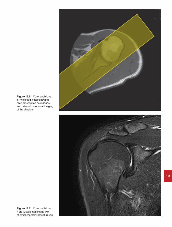
13
Figure 13.6 Coronal/obliqueT1 weighted image showingslice prescription boundariesand orientation for axial imagingof the shoulder.
Figure 13.7 Coronal/obliqueFSE T2 weighted image withchemical/spectral presaturation.
9781405160858_4_013.qxd 28/05/2008 15:37 Page 267
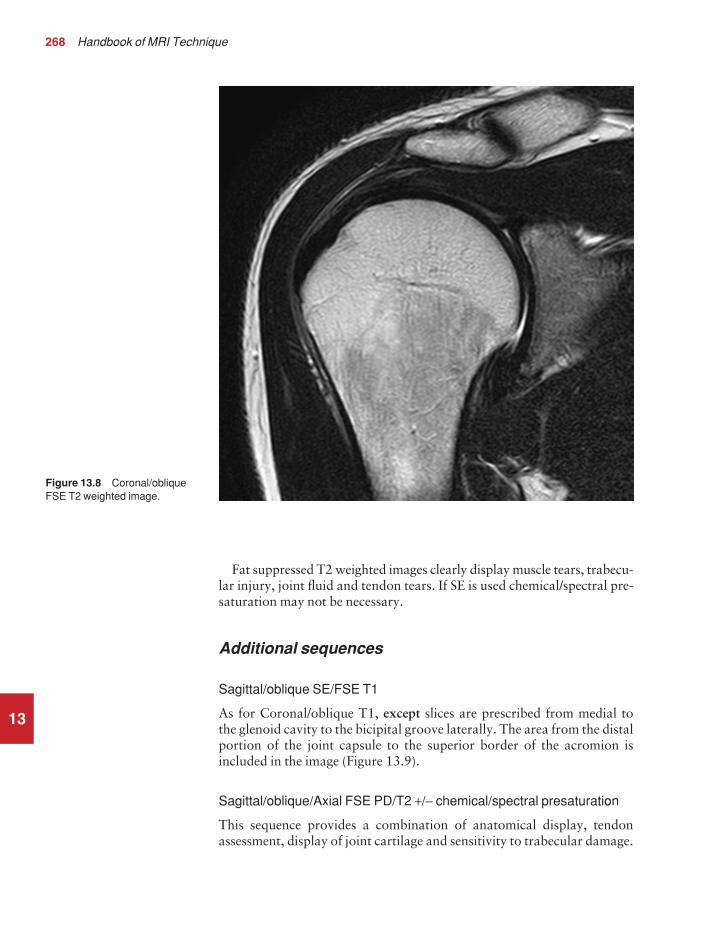
268 Handbook of MRI Technique
13
Fat suppressed T2 weighted images clearly display muscle tears, trabecu-lar injury, joint fluid and tendon tears. If SE is used chemical/spectral pre-saturation may not be necessary.
Additional sequences
Sagittal/oblique SE/FSE T1
As for Coronal/oblique T1, except slices are prescribed from medial to the glenoid cavity to the bicipital groove laterally. The area from the distalportion of the joint capsule to the superior border of the acromion isincluded in the image (Figure 13.9).
Sagittal/oblique/Axial FSE PD/T2 +/− chemical/spectral presaturation
This sequence provides a combination of anatomical display, tendonassessment, display of joint cartilage and sensitivity to trabecular damage.
Figure 13.8 Coronal/obliqueFSE T2 weighted image.
9781405160858_4_013.qxd 28/05/2008 15:37 Page 268
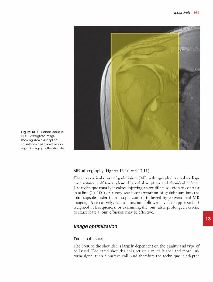
Upper limb 269
13
MR arthrography (Figures 13.10 and 13.11)
The intra-articular use of gadolinium (MR arthrography) is used to diag-nose rotator cuff tears, glenoid labral disruption and chondral defects.The technique usually involves injecting a very dilute solution of contrastin saline (1 : 100) or a very weak concentration of gadolinium into thejoint capsule under fluoroscopic control followed by conventional MRimaging. Alternatively, saline injection followed by fat suppressed T2weighted FSE sequences, or examining the joint after prolonged exerciseto exacerbate a joint effusion, may be effective.
Image optimization
Technical issues
The SNR of the shoulder is largely dependent on the quality and type ofcoil used. Dedicated shoulder coils return a much higher and more uni-form signal than a surface coil, and therefore the technique is adapted
Figure 13.9 Coronal/obliqueGRET2 weighted imageshowing slice prescriptionboundaries and orientation forsagittal imaging of the shoulder.
9781405160858_4_013.qxd 28/05/2008 15:37 Page 269

13
Figure 13.10 Sagittal T1weighted arthrogram.
Figure 13.11 Axial T1weighted arthrogram.
9781405160858_4_013.qxd 28/05/2008 15:37 Page 270

Upper limb 271
accordingly. If using a dedicated coil, thinner slices and finer matrices canbe used to achieve the necessary spatial resolution without unduly length-ening the scan time. If the coil is poor, some resolution may have to besacrificed in order to maintain the SNR and keep the scan time within reasonable limits. However, spatial resolution is the key to accuracy inshoulder imaging and the resolution must not drop below 0.8 mm. SE andFSE are usually the sequences of choice but coherent GRE and STIR areuseful to visualize joint fluid. STIR may provide better results than fatsuppressed FSE if magnet shimming is suboptimal.
Artefact problems
The main sources of artefact are patient movement and flow motion fromthe subclavian vessels. Spatial presaturation pulses placed I and medial to the shoulder under investigation are usually very effective at reducingphase ghosting. GMN also minimizes flow artefact but, as it increases thesignal in vessels and the minimum TE, it is not usually beneficial in T1weighted sequences. However, GMN effectively increases the contrast ofsynovial fluid in T2 and T2* weighted images. Additional shimming maybe required before chemical/spectral presaturation sequences.
Respiration is sometimes troublesome. In coronal/oblique and axialimaging, the FOV is offset so that the centre of the shoulder is in the centreof the image. When using high degrees of obliquity some systems auto-matically swap the direction of phase and frequency encoding axes, whichcan cause severe aliasing problems unless oversampling is utilized. Atangles beyond 45°, some systems may consider a coronal/oblique as asagittal/oblique, altering the presented orientation and the anatomicalmarkers (a right shoulder could look like a left). The same problems canarise in sagittal/oblique imaging. To avoid problems, check the directionof phase encoding for every oblique scan prescription and use anatomicalmarkers in sagittal/oblique images to confirm the scanner’s labelling of anterior and posterior. To minimize aliasing, phase encoding shouldrun A–P on axials and sagittal/obliques, and S–I on the coronal/obliques.Alternatively, spatial presaturation pulses can be positioned to minimizeartefact from the medial edges of the coil.
A phenomenon known as the ‘magic angle’ causes increased signalintensity in tendons in short TE sequences when tendons are orientated atan angle of 55° to the main field. Normally tendons produce little or nosignal on conventional MRI sequences because tendons consist of parallelordered bundles of collagen fibres. This structural anisotropy causes alocal static magnetic field which, when superimposed on to the static field,increases spin–spin interactions and therefore shortens T2 relaxationrates so much that the tendon has a low signal intensity.
However, the rate at which spin dephasing is increased is proportionalto the angle between the main field and the long axis of the tendon.Because of this relationship, additional spin dephasing caused by thestructural anisotropy of tendons decreases to zero when this angle is 55°.
13
9781405160858_4_013.qxd 28/05/2008 15:37 Page 271

272 Handbook of MRI Technique
13
Therefore at this angle the T2 relaxation time increases, causing a highsignal intensity when using short TEs. The increased signal can mimicpathology such as tendonitis in normal tendons. It is seen in many tendonsespecially supraspinatus and Achilles tendons as well as in the wrist. Themagic angle effect can be eliminated by repositioning the tendon or byincreasing the TE above a critical value.
Patient considerations
Ensure that the patient is comfortable and well informed of the procedure.Due to excessively loud gradient noise associated with some sequences,ear plugs must always be provided to prevent hearing impairment.
Contrast usage
Contrast is not routinely used in shoulder imaging except for direct andindirect MR arthrography. For information on direct MR arthrographyplease see previous section under Additional sequences. Indirect MRarthrography involves the administration of intravenous diluted gado-linium and is sometimes used when direct arthrography is not feasible.Although indirect MR arthrography has some disadvantages when com-pared with direct MR arthrography, it does not require fluoroscopic guidance or invasive joint injection. It is also superior to non contrast MRimaging in delineating structures when there is minimal joint fluid. Inaddition, vascularized or inflamed tissue enhances with this method.
9781405160858_4_013.qxd 28/05/2008 15:37 Page 272

Upper limb 273
13
Humerus
Basic anatomy (Figure 13.12)
Figure 13.12 Anterior view ofthe right humerus.
Common indications
• Diagnosis and assessment of bony and soft tissue abnormalities(mass lesions, muscle tears, deformity).
• A single-sided examination is usually preferred as bilateral examina-tions severely compromise resolution.
Equipment
• Body multi-array coil/long surface coil placed under the humerus.• Immobilization pads and straps.• Plastic ruler.• Ear plugs.
9781405160858_4_013.qxd 28/05/2008 15:37 Page 273

274 Handbook of MRI Technique
13
Patient positioning
If the upper arm is under investigation, the patient lies supine on theexamination couch with their arms resting at their sides. If, however, theROI is near the elbow, the patient may lie prone with their arm stretchedabove their head (swimmer’s position). This ensures that the area underexamination is at isocentre and offset imaging is avoided. However, theswimmer’s position can be difficult to maintain for long periods of timeand it is therefore advisable to reserve it for fitter patients. In both posi-tions it is necessary to place the coil lengthwise along the long axis of thehumerus.
When imaging with the arm at the side, raise the unaffected side about 45° and bring the arm under examination as close as possible to thelongitudinal alignment light. The top half of the body array should be positioned with its lateral edge wrapped well around the arm and touch-ing the lower element edge. This avoids placing the arm at the coil edge.Additionally, for full humerus imaging, the top half of the array is slid upto cover the shoulder, while the base portion is used to image from theelbow up. Use immobilization straps to secure the coil, the patient, andsupporting pillows.
If the patient is in the swimmer’s position, the longitudinal alignmentlight lies along the midline of the humerus. In both positions, the hori-zontal alignment light passes through the centre of the coil or midwaybetween the shoulder and the elbow. The arm and coil may be raised withfoam pads until the vertical alignment light lies through the centre of thearm, so avoiding a vertical offset. Use the plastic ruler to measure from thetransverse alignment light to the joints to ensure the full length of the armfits within the long axis of the FOV. If not, include either the shoulder orelbow depending on the location of the lesions. When a lesion is palpableplace an oil- or water-filled marker over it. For large lumps or scars place amarker at each end.
Suggested protocol
Coronal/Sagittal incoherent (spoiled) SE/FSE T1
Acts as a localizer if three-plane localization is unavailable but, if thepatient has been positioned correctly, it may act as a diagnostic sequence.Coronal localizers should be used for lesions located in the RL axis, sagittallocalizers for lesions in the AP axis.
Coronal imaging: Medium slices/gap are prescribed on either side of thevertical alignment light and offset to the middle of the humerus (if the armis at the side). No offset is necessary in the swimmer’s position as the longitudinal alignment light corresponds to the middle of the humerus.The whole of the humerus, from the elbow to the shoulder, is included inthe image.
P 25 mm to A 25 mm
9781405160858_4_013.qxd 28/05/2008 15:37 Page 274

Upper limb 275
Sagittal imaging: Medium slices/gap are prescribed on either side of thelongitudinal light in the swimmer’s position, or on either side of the offsetmeasurement when imaging with the arms at the side. The whole of thehumerus, from the elbow to the shoulder, is included in the image.
L 25 mm to R 25 mm(swimmer’s position)
Sagittal STIR
Medium slices/gap are prescribed to cover the whole of the humerus fromthe glenoid to the proximal radius and ulna, and orientated along the longaxis of the humerus. This sequence is useful to identify lesions in the softtissues and marrow space and display their extent.
Coronal FSE/SE T1
Thin slices/gap are prescribed to cover the humerus from back to frontand orientated along the long axis of the humerus. This sequence providesan anatomical display of the upper arm and may identify lesions locatedin the marrow space.
Axial SE/FSE T1
Medium slices/gap are prescribed and positioned to include lesions seenon the coronal or sagittal images. Axial images are used to localize lesionswithin significant anatomical compartments and must extend well aboveand below the lesions. Breach of the marrow space, extension within orthrough muscle compartments and association with the neurovascularbundle are all significant characteristics.
Axial FSE T2 chemical/spectral presaturation/STIR
Slice prescription as for Axial T1.STIR sequences are usually needed if the arm is by the side or if the ROI
is away from the longitudinal isocentre. Chemical/spectral presaturationis more effective in the swimmer’s position when the ROI is at isocentre.
Image optimization
Technical issues
The inherent contrast is relatively good in this area due to the appositionof muscle and fat. Medium slice thickness and resolution, combined withsensitive coils, permit a fast examination so that higher-resolution axialimages can be acquired when lesions are close to the neurovascular bundle, or cortical bone breach is not obvious.
13
9781405160858_4_013.qxd 28/05/2008 15:37 Page 275

276 Handbook of MRI Technique
13
The FOV is usually extended on the coronals and sagittals so that theentire length of the humerus is visualized. This is especially important inthe diagnosis of bony tumours to ensure that any additional skip lesionsare identified. The associated scan time reductions of FSE enable theimplementation of medium to fine matrices, without unduly lengtheningthe scan time. In the coronal and sagittal planes, a rectangular/asymmetricFOV is beneficial to maintain resolution with the long axis of the rectangleplaced S to I. In coronal imaging an offset square FOV or oversampling isrequired to avoid aliasing, especially when using a large coil.
When using FSE with T2 weighting, the muscles return a lower signalthan in SE and fat returns a higher signal (see Pulse sequences in Part 1).Chemical/spectral presaturation techniques are, therefore, usually neces-sary to distinguish fat from pathology. Multiple NEX/NSA are requiredto compensate for this or, alternatively, the coil can be placed anteriorlyover the arm.
Artefact problems
Patient movement is sometimes troublesome in the swimmer’s position asthe patient is more likely to be uncomfortable. Careful immobilization orlaying the patient supine instead is beneficial. Pulsation from the humeralvessels is reduced by using spatial presaturation pulses placed S and I tothe FOV and I on axial imaging. Medial spatial presaturation pulses alsoreduce aliasing. GMN can be implemented but, as it increases the signal in vessels and the minimum TE, it is not usually beneficial in T1 weightedsequences. Chemical shift artefact must be kept within one pixel, particu-larly in axial imaging, to delineate the interface of marrow and corticalbone and the edges of muscle compartments clearly. Additional shimmingmay be required before chemical/spectral presaturation sequences.
Patient considerations
Patients must be carefully positioned if the swimmer’s position is used andimmobilized with foam pads for comfort. To allow accurate assessmentof mass lesions, MRI should be performed before biopsy. Due to excess-ively loud gradient noise associated with some sequences, ear plugs mustalways be provided to prevent hearing impairment.
Contrast usage
Contrast may be useful for visualizing some soft tissue abnormalities butit is not routinely used.
9781405160858_4_013.qxd 28/05/2008 15:37 Page 276

Upper limb 277
13
Elbow
Basic anatomy (Figures 13.13 and 13.14)
Figure 13.13 Anterior view ofthe right elbow showing thebony components.
Common indications
• Osteochondral defects and loose bodies.• Ulnar nerve compression.• Trauma, particularly ulnar collateral ligament injury.• Soft tissue mass lesions.• Muscle tear and rupture.
Equipment
• Small surface coils combined as an array/Helmholtz pair/flexiblecoils/surface coil fixed anteriorly to the joint.
• Immobilization pads and straps.• Plastic elbow slabs.• Ear plugs.
9781405160858_4_013.qxd 28/05/2008 15:37 Page 277
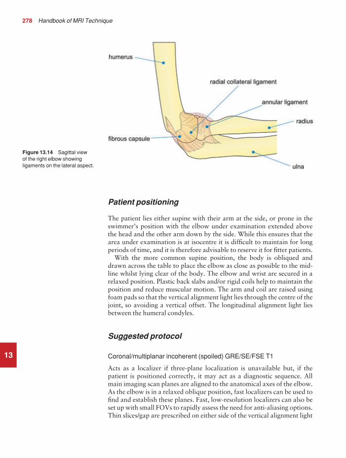
278 Handbook of MRI Technique
13
Patient positioning
The patient lies either supine with their arm at the side, or prone in theswimmer’s position with the elbow under examination extended abovethe head and the other arm down by the side. While this ensures that thearea under examination is at isocentre it is difficult to maintain for longperiods of time, and it is therefore advisable to reserve it for fitter patients.
With the more common supine position, the body is obliqued anddrawn across the table to place the elbow as close as possible to the mid-line whilst lying clear of the body. The elbow and wrist are secured in arelaxed position. Plastic back slabs and/or rigid coils help to maintain theposition and reduce muscular motion. The arm and coil are raised usingfoam pads so that the vertical alignment light lies through the centre of thejoint, so avoiding a vertical offset. The longitudinal alignment light liesbetween the humeral condyles.
Suggested protocol
Coronal/multiplanar incoherent (spoiled) GRE/SE/FSE T1
Acts as a localizer if three-plane localization is unavailable but, if thepatient is positioned correctly, it may act as a diagnostic sequence. Allmain imaging scan planes are aligned to the anatomical axes of the elbow.As the elbow is in a relaxed oblique position, fast localizers can be used tofind and establish these planes. Fast, low-resolution localizers can also beset up with small FOVs to rapidly assess the need for anti-aliasing options.Thin slices/gap are prescribed on either side of the vertical alignment light
Figure 13.14 Sagittal view of the right elbow showingligaments on the lateral aspect.
9781405160858_4_013.qxd 28/05/2008 15:37 Page 278

Upper limb 279
13
or with an offset if the arms are at the side. The whole of the elbow joint isincluded in the image.
Coronal localizer: P 20 mm to A 20 mm
Coronal SE/FSE T1 (Figure 13.15)
Thin slices/gap are prescribed through a line joining the humeral epicondylesfrom the posterior to the anterior skin surfaces. The distal humerus,elbow joint and proximal radius and ulna, including the lateral and medialskin margins, are included on the image.
Coronal FSE PD/T2 +/− chemical/spectral presaturation/ STIR (Figures 13.16 and 13.17)
Slice prescription as for Coronal T1, except use chemical/spectral presat-uration for identification of occult fractures and joint degeneration.
Sagittal SE/FSE T1
Thin slices/gap are prescribed perpendicular to the coronal slices from themedial to the lateral aspects of the elbow (Figure 13.18). This sequence isused to evaluate lesions anterior or posterior to the bony anatomy andassess the long axis of associated muscles and tendons.
Sagittal STIR (Figure 13.19)
Slice prescription as for Sagittal T1.
Axial FSE T1 or PD/T2 +/− chemical/spectral presaturation (Figure 13.21)
Thin slices/gap are aligned perpendicular to the long axis of the humerusand forearm, as determined from a coronal view (Figure 13.20). Theseslices are typically oblique, with the medial edge more inferior than thelateral edge.
Coherent GRE T2* +/− chemical/spectral presaturation
These images display articular cartilage clearly for clarifying osteochondraldefects.
Additional sequences
Incoherent (spoiled) GRE T1
Reduced signal intensity in the marrow space due to susceptibility effects,combined with high signal from muscle, makes this sequence useful inexamining elbow joint anatomy.
9781405160858_4_013.qxd 28/05/2008 15:37 Page 279

13
Figure 13.15 Coronal SE T1weighted image of the elbowshowing normal appearances.
Figure 13.16 Coronal FSE T2 weighted image of the elbow with chemical/spectralpresaturation showing normalappearances.
9781405160858_4_013.qxd 28/05/2008 15:37 Page 280

13
Figure 13.17 Coronal STIR.
Figure 13.18 Coronal SE T1weighted image of the elbowshowing slice prescriptionboundaries and orientation forsagittal imaging of the elbow.
9781405160858_4_013.qxd 28/05/2008 15:37 Page 281

282 Handbook of MRI Technique
13
Coronal 3D coherent GRE PD/T2*
Thin slices and a small number of slice locations are prescribed throughthe joint allowing for slice wrap. The use of an isotropic dataset providesfurther evaluation of the elbow joint.
Image optimization
Technical issues
High-resolution imaging is required to demonstrate the elbow joint and therefore image quality is mainly dependent on the quality of the coil used. If a coil pair or array is implemented, the necessary spatial resolution can be easily maintained. In most cases the FOV is close to the periphery of the magnet bore and, therefore, extra shimming may be required to maximize SNR and image quality. FSE is commonly usedto maintain high resolution in acceptable scan times. FSE also providesgood contrast, but when used with T2 weighting the muscles return alower signal than in SE and fat remains bright (see Pulse sequences in Part 1). Chemical/spectral presaturation is, therefore, often necessary to
Figure 13.19 Sagittal STIR.
9781405160858_4_013.qxd 28/05/2008 15:37 Page 282

13
Figure 13.20 Coronal SE T1weighted image of the elbowshowing slice prescriptionboundaries and orientation foraxial imaging of the elbow.
Figure 13.21 Axial FSE T1weighted image through theelbow joint.
9781405160858_4_013.qxd 28/05/2008 15:38 Page 283

284 Handbook of MRI Technique
distinguish fat from pathology. Coherent GRE sequences are also used as they provide good contrast between the bony margins of the joint and synovial fluid. Volume acquisitions are sometimes valuable as verythin slices with no gap are used, and joint structures may be visualized in any plane.
Artefact problems
Patient movement can be troublesome in the swimmer’s position as thepatient is more likely to be uncomfortable. Careful immobilization, orlaying the patient supine instead, is beneficial. Pulsation from the humeraland radial vessels is reduced using spatial presaturation pulses placed Sand I to the FOV. GMN can also be used but, as it increases signal in vessels and the minimum TE, it is not usually beneficial in T1 weightedsequences. However, GMN effectively increases the contrast of synovialfluid in T2 and T2* weighted images. If offset imaging is employed andphase is S to I, oversampling is necessary on the coronals. In axial imagingthere is no anatomy outside the FOV in the phase direction, and in sagittalimaging there is no offset. Therefore oversampling is usually unnecessaryin these planes. Additional shimming may be required before chemical/spectral presaturation sequences.
Patient considerations
Patients must be carefully positioned if the swimmer’s position is used and immobilized with pads for comfort. Due to excessively loud gradientnoise associated with some sequences, ear plugs must always be providedto prevent hearing impairment.
Contrast usage
Contrast may be useful for visualizing some soft tissue abnormalities. In addition, MR arthrography is useful for visualizing partial- and full-thickness tears of the collateral ligament and delineating bands in theelbow.
13
9781405160858_4_013.qxd 28/05/2008 15:38 Page 284

Upper limb 285
13
Forearm
Basic anatomy (Figure 13.22)
Figure 13.22 Anterior view ofthe right radius and ulna.
Common indications
• Visualization of bony and soft tissue abnormalities.
Equipment
• Body array coil/long surface coil placed under the arm/extremitycoil for focal lesions/body coil.
• Immobilization pads and straps.• Plastic ruler.• Ear plugs.
Patient positioning
The patient may lie either supine with the arms at the side, or prone in theswimmer’s position with the arm under investigation above the head and
9781405160858_4_013.qxd 28/05/2008 15:38 Page 285

286 Handbook of MRI Technique
13
the other arm down by the side. This ensures that the area under examina-tion is at isocentre and offset imaging is avoided. However, this position isdifficult to maintain for long periods of time and it is therefore advisableto reserve it for fit patients.
When imaging with the arm at the side, raise the unaffected side about45° and bring the arm under examination as close as possible to the centreof the bore. The top half of the body array should be positioned with itslateral edge wrapped well around the arm and touching the lower elementedge. This avoids using the edge of the coil. In addition, when imaging the whole of the forearm, the top half of the array is slid up to cover theelbow, while the base portion is used to image from the wrist up. Whilekeeping the arm relaxed it is important to avoid pronation of the hand.Use immobilization straps to secure the coil, patient, and supporting pillows or pads. Instruct the patient not to move their fingers during dataacquisition.
In both positions, the horizontal alignment light passes through thecentre of the coil or midway between the elbow and the wrist. The armand coil may be raised with foam pads until the vertical alignment lightlies through the centre of the arm, so avoiding a vertical offset. Use theplastic ruler to measure from the horizontal alignment mark to each joint.This ensures that the full length of the forearm fits within the FOV. If thisis not possible include either the elbow or the wrist depending on the loca-tion of the lesions. When a lesion is palpable place an oil- or water-filledmarker over it. For large lumps or scars place a marker at each end.
Suggested protocol
Multiplanar/Coronal/Sagittal incoherent (spoiled) GRE/SE/FSE T1
Acts as a localizer if three-plane localization is unavailable but, if thepatient has been positioned correctly, may act as a diagnostic sequence.Coronal localizers should be used for lesions located in the RL axis, sagittallocalizers for lesions in the AP axis. Surface coil localizers can be used to quickly assess potential aliasing problems and for establishing anatom-ical planes.
Coronal imaging: Medium slices/gap are prescribed on either side of the vertical alignment light and offset to the middle of the forearm (if thearm is at the side). No offset is necessary in the swimmer’s position as the longitudinal alignment light corresponds to the middle of the forearm.The whole of the forearm from the wrist to the elbow is included in the image.
P 25 mm to A 25 mm
Sagittal imaging: Medium slices/gap are prescribed on either side of thelongitudinal light in the swimmer’s position or on either side of the offset
9781405160858_4_013.qxd 28/05/2008 15:38 Page 286

Upper limb 287
measurement when imaging with the arms at the side. The whole of theforearm from the wrist to the elbow is included in the image.
L 25 mm to R 25 mm(swimmer’s position)
Sagittal STIR
Medium slices/gap are prescribed to include the whole forearm from thedistal humerus to the proximal metacarpals and orientated along the longaxis of the humerus accounting for the ‘carry angle’ of the forearm. Thissequence is fast and sensitive for identifying lesions in the soft tissues andmarrow space.
Coronal FSE/SE T1
Thin slices/gap are prescribed along the line of the forearm and from theposterior to the anterior skin surfaces.
Axial T1 FSE
Medium slices/gap are prescribed perpendicular to the coronal slices toextend well above and below lesions seen in this, and the sagittal plane.Breach of the marrow space, extension within or through muscle com-partments, and association with the neurovascular bundle are all significantcharacteristics best assessed on axial images.
Axial FSE T2 +/− chemical/spectral presaturation or STIR
Slice prescription as for Axial T1.STIR sequences are usually required if the arm is by the side or if the
ROI is away from the isocentre. Chemical/spectral presaturation is effect-ive with the swimmer’s positioning. The FSE sequence is optimal as it provides better resolution than STIR.
Image optimization
Technical issues
The inherent contrast is relatively good in this area due to the appositionof muscle and fat. Medium slice thickness and resolution, combined withsensitive coils, permit a fast examination so that high resolution axialimages may be acquired for lesions close to the neurovascular bundle andwhen cortical bone-breach is not obvious. The FOV is usually extendedon the coronals and sagittals so that the entire length of the forearm isvisualized. This is especially important in the diagnosis of bony tumoursto ensure that any additional skip lesions are identified. The associated
13
9781405160858_4_013.qxd 28/05/2008 15:38 Page 287

288 Handbook of MRI Technique
13
scan time reductions of FSE enable the implementation of medium to finematrices, without unduly lengthening the scan time. In the coronal andsagittal planes, a rectangular/asymmetric FOV is useful with the long axisof the rectangle running along the length of the forearm. When using FSEwith T2 weighting, the muscles return a lower signal than in SE and fatreturns a higher signal. Chemical/spectral presaturation techniques are,therefore, usually necessary to distinguish fat from pathology. Spectral fatsuppression is difficult to achieve over a large FOV in the periphery of thehomogeneous field, so STIR is typically used in coronal and sagittalimages. Axial images near isocentre in the longitudinal direction can usu-ally support chemical fat suppression.
Artefact problems
Patient movement is sometimes troublesome in the swimmer’s position as the patient is more likely to be uncomfortable. Careful immobilization,or laying the patient supine instead, is beneficial. Pulsation from the radialvessels is reduced using spatial presaturation pulses placed S and I to theFOV. GMN can also be used but, as it increases the signal in vessels andthe minimum TE, it is not usually beneficial in T1 weighted sequences.
Patient considerations
Patients must be carefully positioned if the swimmer’s position is used, and immobilized with foam pads for comfort. Due to excessively loudgradient noise associated with some sequences, ear plugs must always beprovided to prevent hearing impairment.
Contrast usage
Contrast may be useful for visualizing some soft tissue abnormalities butit is not routinely used.
9781405160858_4_013.qxd 28/05/2008 15:38 Page 288

Upper limb 289
13
Wrist and hand
Basic anatomy (Figure 13.23)
Figure 13.23 Bony structuresof the wrist.
Common indications
• Assessment of wrist pain of unknown origin (tears of the triangularcartilage, osteonecrosis of the lunate (Kienböch’s disease), occultganglia).
• Assessment of avascular necrosis (AVN) of the scaphoid followingtrauma.
• Diagnosis of carpal tunnel syndrome.• Possibly valuable in early evaluation of rheumatoid arthritis.• Assessment of the scapholunate and scaphotriquetral ligaments
when wrist instability is suspected.
Equipment
• Dedicated wrist coil (volume/Helmholtz/phased or multi-coil array)/small surface coil(s) linked by a phase harness. Very small, speciallydesigned, local coils can be used to examine finger joints.
• Immobilization pads and straps.• Ear plugs.
9781405160858_4_013.qxd 28/05/2008 15:38 Page 289
290 Handbook of MRI Technique
13
Patient positioning
The patient is usually scanned lying supine with the arm by the side withthe elbow and wrist facing up to avoid pronation of the forearm. Thewrist and hand are placed in a splint to prevent movement, and to aidsecure coil placement. Move the patient as far as possible across the tableand support the entire arm on pads to bring the wrist as close as possibleto isocentre. Fit patients may be able to tolerate the swimmer’s positionwith the palm either facing up or down with the arm bent at the elbow. Ifa small circular coil is used, the patient can be positioned prone or supinewith the arm above the head and elbow bent so that the forearm runsacross the table. The coil is fixed in the sagittal plane at vertical isocentre.If two coils are used the wrist is placed through them to take advantage ofboth of the sensitive areas of the coils. As this requires active coil decoup-ling check your system’s operation manuals if in doubt. If the wrist is atisocentre in all three axes, the longitudinal and horizontal alignmentlights are centred to the wrist. If the arm is at the side it may be necessaryto measure the horizontal offset with a plastic ruler.
Suggested protocol
Multiplanar/Sagittal SE/FSE/incoherent (spoiled) GRE T1/coherentGRE T2* (Figure 13.24)
Acts as a localizer if three-plane localization is unavailable but, if thepatient has been positioned correctly, may act as a diagnostic sequence.Using the body coil, medium slices/gap are prescribed on either side of the longitudinal light in the swimmer’s position or on either side of theoffset with the arm at the side. The area from the inferior border of the carpal bones to the distal portion of the forearm is included in theimage.
L 15 mm to R 15 mm(swimmer’s position)
Axial localizer: This may be prescribed from the multiplanar localizers orthe sagittal localizer. Use a surface coil to determine slice orientation forcoronal imaging more accurately (Figure 13.25).
Coronal SE/FSE T1 (Figure 13.26)
Thin slices/gap or interleaved are prescribed through the joint or ROI par-allel to the proximal row of the carpus as seen from the axial localizers(the distal radioulnar joint is frequently not aligned with the carpus).Displace slices inferiorly for the carpal tunnel. The area from the inferiorborder of the carpal bones to the distal portion of the forearm is includedin the image.
9781405160858_4_013.qxd 28/05/2008 15:38 Page 290

13
Figure 13.24 Sagittal GRET2* weighted localizer of thewrist showing slice prescriptionboundaries and orientation forcoronal imaging.
Figure 13.25 Axial GRE T2*weighted localizer of the wristshowing slice prescriptionboundaries and orientation forcoronal imaging.
9781405160858_4_013.qxd 28/05/2008 15:38 Page 291

292 Handbook of MRI Technique
13
Coronal SE/FSE T2 or coherent GRE T2* +/− chemical/spectralpresaturation (Figures 13.27 and 13.28)
Slice prescription as for Coronal T1.These sequences are useful for investigating the triangular fibrocarti-
lage, fractures or AVN. STIR is not commonly used due to poor SNR and,therefore, good resolution is difficult to obtain.
Axial FSE T2 (Figure 13.29)
Thin slices/gap are prescribed through the ROI orientated parallel to theproximal row of carpal bones as seen on the coronal images (Figure 13.30).
Axial FSE T1 (Figure 13.31)
Slice prescription as for Axial T2.This sequence is useful for carpal tunnel syndrome and ulnar nerve
lesions.
Figure 13.26 Coronal FSE T1weighted image of the wristshowing normal appearances.
9781405160858_4_013.qxd 28/05/2008 15:38 Page 292

13
Figure 13.27 Coronalcoherent GRE T2*.
Figure 13.28 Coronal FSE T2weighted image of the wrist withchemical/spectral presaturation.
9781405160858_4_013.qxd 28/05/2008 15:38 Page 293

13
Figure 13.29 Axial FSE T2weighted image through thecarpel tunnel.
Figure 13.30 Coronal FSE T1weighted image showing sliceprescription boundaries andorientation for axial imaging ofthe wrist.
9781405160858_4_013.qxd 28/05/2008 15:38 Page 294

Upper limb 295
13
Additional sequences
Axial PD + chemical/spectral presaturation (Figure 13.32)
Slice prescription as for Axial T2.This sequence is useful for visualization of articular cartilage and carpal
tunnel.
Sagittal SE/FSE T1
Thin slices/gap are prescribed orientated perpendicular to the coronalplane. This sequence is useful for localizing dorsal ganglia (Figure 13.33).
3D incoherent (spoiled) GRE T1 or coherent GRE T2* (Figure 13.34)
Used to investigate fluid or solid pathologies with thin slices but at theexpense of resolution. Hybrid sequences showing anatomy and fluid arealso popular. Thin slices and a small number of slice locations are pre-scribed through the joint allowing for slice wrap.
Figure 13.31 Axial FSE T1weighted image of the wristclearly demonstrating the carpal tunnel.
9781405160858_4_013.qxd 28/05/2008 15:38 Page 295

13
Figure 13.32 Axial FSE PDwith chemical/spectralpresaturation.
Figure 13.33 Coronal FSE T1weighted image showing sliceprescription boundaries andorientation for sagittal imagingof the wrist.
9781405160858_4_013.qxd 28/05/2008 15:38 Page 296

Upper limb 297
13
Image optimization
Technical issues
The quality of the coil is very important in the wrist. The inherent SNRand CNR are relatively low as most of the structures are bony, and there is little fat. The use of a dedicated wrist coil ensures a high and uniformsignal return, so that the high resolution required in the wrist is easilyobtained. Multiple NEX/NSA may also be necessary to improve the SNR.Very small, specially designed, surface coils may be used to examine thefingers individually. However, this type of examination is not very com-mon at present.
High spatial resolution is essential to display the fine anatomy of the wrist adequately and therefore fine matrices and thin slices and inter-leaving are required. FSE is commonly utilized although longer ETLs and echo spacing may induce significant blurring, or compromise thediagnosis of tendon pathology in T1 weighted images (see Pulse sequencesin Part 1).
Figure 13.34 Coronal slicefrom a 3D T1 weighted data set.
9781405160858_4_013.qxd 28/05/2008 15:38 Page 297

298 Handbook of MRI Technique
Artefact problems
There is little artefact in this area as the vessel pulsations are not particu-larly strong but spatial presaturation pulses placed S and I to the FOVreduce phase ghosting. GMN is not usually required to decrease flow arte-fact in the wrist but it effectively increases the contrast of the synovialfluid in T2 and T2* weighted images. Patient movement may be trouble-some in the swimmer’s position, especially if the scan times are lengthy. Itis, therefore, necessary to ensure that the patient is carefully immobilizedand comfortable. Instruct the patient not to move their fingers during thesequences. Motion induced by discomfort is often a problem no matterwhat positioning is used. Fat suppression is difficult in the periphery of thehomogenous region of the magnet. Shimming improves chemical fat sup-pression and the quality of longer TE GRE sequences. All metal should beremoved from the patient’s clothing and body to preserve a good shim. RFblankets or shields can be used to screen signal from the patient’s body,obviating the need for oversampling in many cases. Alternatively, spatialpresaturation pulses can be used to null signal from the body.
Patient considerations
Inform the patient of the possibly lengthy scan times and the import-ance of keeping still. Ensure that the patient is comfortable and wellimmobilized.
Due to excessively loud gradient noise associated with some sequences,ear plugs must always be provided to prevent hearing impairment.
Contrast usage
Contrast is not routinely used in the wrist; however MR arthrography issometimes useful in increasing the certainty of seeing perforations of theligaments and triangular fibrocartilage.
13
9781405160858_4_013.qxd 28/05/2008 15:38 Page 298

14
14Hips 301Femur 310Knee 314Tibia and fibula 325Ankle 329Foot 336Vascular imaging 343
Lower limb
299
9781405160858_4_014.qxd 28/05/2008 15:39 Page 299

300 Handbook of MRI Technique
14
Table 14.1 Summary of parameters. The figures given are general and should beadjusted according to the system used (Table 2.1)
Spin echo (SE)short TE min to 30 mslong TE 70 ms +short TR 300–600 mslong TR 2000 ms +
Fast spin echo (FSE)short TE min–20 mslong TE 90 ms +short TR 400–600 mslong TR 4000 ms +short ETL 2–6long ETL 16 +
Inversion recovery (IR) T1short TE min–20 mslong TR 3000 ms +medium TI 200–600 msshort ETL 2–6
STIRlong TE 60 ms +long TR 3000 ms +short TI 100–175 mslong ETL 12–20
FLAIRlong TE 60 ms +long TR 3000 ms +long TI 1700–2200 mslong ETL 12–20
Slice thickness2D thin 2–4 mm
medium 5–6 mmthick 8 mm
3D thin ≤ 1 mmthick ≥ 3 mm
FOVsmall ≤ 18 cmmedium 18–30 cmlarge ≥ 30 cm
NEX/NSAshort ≤ 1medium 2–3multiple ≥ 4
Coherent GRElong TE 15 ms +short TR ≤ 50 msflip angle 20°–40°
Incoherent GREshort TE min–5 msshort TR ≤ 50 msflip angle 20°–40°
Balanced GRETE minimumTR minimumflip angle ≥ 40°
SSFPTE minimumTR 40–50 msflip angle 20°–40°
Slice numbersVolumes small ≤ 32
medium 64large ≥ 128
Matrix (frequency ×× phase)coarse 256 × 128 or 256 × 192medium 256 × 256 or 512 × 256fine 512 × 512very fine ≥ 512 × 512
PC-MRA2D and 3D TE minimum
TR 25–33 msflip angle 30°
VENC venous 20–40 cm/sVENC arterial 60 cm/s
TOF-MRA2D TE minimum
TR 28–45 msflip angle 40°–60°
3D TE minimumTR 25–50 msflip angle 20°–30°
9781405160858_4_014.qxd 28/05/2008 15:39 Page 300

Lower limb 301
Hips
Basic anatomy (Figure 14.1)
14
Figure 14.1 Anterior view ofthe right hip demonstrating bonycomponents and ligaments.
Common indications
• Evaluation of unexplained unilateral or bilateral hip pain.• Suspected occult fracture.• Muscle tears.• Labral tears, chondral damage or other joint soft tissue pathology.
Note: Bilateral and unilateral examinations of the hips are described inthis section. The causes of generalized hip pain include AVN, metastaticdeposits and occult fractures, which may affect both hips. Specific unilat-eral joint pathologies such as suspected labral tears or chondral damagerequire high-resolution imaging of the hip in question. However, due tothe prevalence of AVN in patients presenting with hip pain, it is advisableto include a bilateral sequence in unilateral hip protocols.
Equipment
Bilateral hip imaging
• Body phased array/multi-coil array/general-purpose flexible coil/body coil.
9781405160858_4_014.qxd 28/05/2008 15:39 Page 301

302 Handbook of MRI Technique
• Immobilization pads and straps.• 20° wedge sponges.• Ear plugs.
Single hip imaging
• Small/large flexible coil/multi-coil array/pelvis phased array/smallHelmholtz pair.
• Immobilization pads and straps.• 20° wedge sponges.• Ear plugs.
Patient positioning
The patient lies supine on the examination couch with their legs straightand both feet parallel to each other. This ensures that the angle of bothfemoral necks is the same, although they do not necessarily have to beinternally rotated as in radiography of the hips. The legs are immobilizedwith the use of pads and straps wrapped around both feet. This enablesthe patient to maintain the position in a relaxed fashion.
The patient is positioned so that the longitudinal alignment light lies in the midline, and the horizontal alignment light passes through the levelof the femoral heads. They are localized by palpating the femoral pulse,which is typically found 3 cm inferiorly and laterally to the midpoint of the line joining the anterior superior iliac spine (ASIS) and the pubicsymphysis. If only one hip is imaged the FOV will be offset from isocentreand image quality may be affected.
Suggested protocol – bilateral examination
Axial SE/FSE/incoherent (spoiled) GRE T1
Acts as a localizer if three-plane localization is unavailable, or as a diagnostic sequence. Thick slices/gap are prescribed on either side of thehorizontal alignment light. Both hips are included to show the locationand alignment of the hips.
Axial I 25 mm to S 25 mm
Coronal FSE T2 +/− chemical/spectral presaturation/STIR
Thin slices/gap are prescribed from the posterior to the anterior marginsof the musculature of the hip (from the iliacus to the anterior portion ofgluteus maximus). Slices may be angled to compensate for positional rota-tion of the pelvis. The images should display the lateral edges of the mus-cles surrounding the hips (gluteus medius), and extend from the junctionof the ilium and the superior acetabulum to below the lesser trochanter.
14
9781405160858_4_014.qxd 28/05/2008 15:39 Page 302

Lower limb 303
Coronal SE/FSE T1 (Figure 14.2)
Slice prescription as for Coronal T2.
Axial SE/FSE T1
Thin slices/gap are prescribed from above the articular portion of theacetabulum to the superior edge of the lesser trochanter, and aligned withthe superior surface of both femoral heads to correct for positional errors(Figure 14.3).
Sagittal FSE T2/coherent GRE T2* +/− chemical/spectral presaturation
Thin slices/gap are prescribed from the lateral aspect of the greater troch-anter through the articular portions of the acetabulum (Figure 14.4).These images particularly demonstrate flattening of the femoral headassociated with AVN. Generally, FSE is the sequence of choice but GREsequences provide excellent visualization of cartilage.
14
Figure 14.2 Coronal FSE T1image of both hips and femora.
9781405160858_4_014.qxd 28/05/2008 15:39 Page 303

14
Figure 14.3 Coronal FSE T1weighted image showing sliceprescription boundaries andorientation for axial imaging ofthe hips.
Figure 14.4 Coronal FSE T1weighted image showing sliceprescription boundaries andorientation for sagittal imagingof the hips.
9781405160858_4_014.qxd 28/05/2008 15:39 Page 304

Lower limb 305
Suggested protocol – unilateral examination
This examination usually demands higher resolution than bilateral exams.Image planes should be placed relative to the anatomy of the joint ratherthan orthogonal to the body. Extra shimming may be required to optimizechemical/spectral presaturation performance and GRE image quality inan offset FOV.
Axial SE/FSE/incoherent (spoiled) GRE T1
Acts as a localizer if three-plane localization is unavailable, or as a diagnostic sequence. As for bilateral examination. Use the body coil andinclude both hips.
Coronal SE/FSE T1
Thin slices/gap are prescribed from the posterior to the anterior marginsof the femoral head and aligned parallel to the femoral neck. The areafrom the proximal margin of the femoral shaft (below the lesser troch-anter) to the greater sciatic notch is included in the image.
Coronal coherent GRE T2*/FSE T2 +/− chemical/spectral presaturation
Slice prescription as for the Coronal T1.T2* images are particularly good for identifying the labrum and
loose bodies in the joint. A FSE T2 may be preferred to provide higher resolution.
Axial FSE T2 +/− chemical/spectral presaturation
Thin slices/gap are prescribed from a coronal image to include the articu-lar components of the hip joint. Angle the slices so that they are parallel tothe femoral neck.
Axial SE/FSE/incoherent (spoiled) GRE T1
Slice prescription as for Axial T2.
Additional sequences
Coronal FSE T2 +/− chemical/spectral presaturation (both hips)
This may be used as an additional sequence to the unilateral examination,especially to rule out AVN of the asymptomatic hip. Use the body coil toavoid repositioning of the patient. Medium slice/gap is adequate as thecontrast sensitivity of the sequence should identify pathology. Positionslices to include the bony components of the hip joint and some surround-ing musculature.
14
9781405160858_4_014.qxd 28/05/2008 15:39 Page 305

306 Handbook of MRI Technique
SE/FSE/incoherent (spoiled) GRE T1 + contrast (Figures 14.5 and 14.6)
This sequence may be used after intra-articular injection of contrast to visualize labral tears and chondral defects. A very dilute solution ofgadolinium contrast agent in saline (1 : 100) is introduced into the jointcapsule and the single joint is imaged at high resolution with chemical/spectral presaturation. T1 weighted images in three planes are acquiredaligned to the femoral neck and acetabular rim.
Image optimization
Technical issues
Spatial resolution is a critical parameter in joint imaging and depends onthe clinical indications. For example, when examining small labral tears,resolution is paramount and utilization of thin slices/gap and a fine matrixis necessary. However, when the lesion is large and CNR is high, resolu-tion can be sacrificed to achieve better SNR or shorter scan times. Volume
14
Figure 14.5 Coronalarthrogram.
9781405160858_4_014.qxd 28/05/2008 15:39 Page 306

Lower limb 307
acquisitions are sometimes valuable as very thin slices with no gap areused, and joint structures may be visualized in any plane. As volumeacquisitions are usually performed in order to demonstrate anatomy, an incoherent (spoiled) GRE sequence that produces predominantly T1weighting is required.
Bilateral and unilateral examinations have been described in this section. Bilateral imaging with a large phased array coil has a number of advantages. It can provide acceptable resolution for visualizing jointstructures when used with a combination of a small FOV and oversam-pling, but it can also be utilized with a large FOV to provide medium-resolution images of a large area of anatomy. For unilateral examinationsthe requirement for fine spatial resolution is paramount. The hip jointstructures are comparable in size to the shoulder, demanding spatial reso-lution of less than 0.5 mm. Unfortunately, the relatively bulky musculat-ure and the external morphology of the hip demands physically largercoils. As a result it may be necessary to use higher NEX/NSA and longerscan times to achieve acceptable SNR.
Flexible selection of a rectangular/asymmetric FOV has greatly helpedto tailor hip sequences in the axial and sagittal planes. In addition, flexible
14
Figure 14.6 Axial arthrogram.
9781405160858_4_014.qxd 28/05/2008 15:39 Page 307

308 Handbook of MRI Technique
application of oversampling allows a small FOV to be used in the coronaland axial planes in conjunction with larger coils, as well as providing finerincremental changes in SNR.
Several sequences are employed in hip examinations. SE sequences usually provide better contrast and resolution in T1 weighted images than FSE. However, the development of high-performance gradients,which permit short ETLs and echo spacing improve resolution. Chemical/spectral presaturation is an important imaging option in the musculo-skeletal system, as the suppression of normal fatty marrow often enhancesthe visualization of bony pathology. Chemical/spectral presaturationtechniques are usually preferred, but STIR sequences provide very uni-form fat suppression, particularly on older systems and in large FOVs. In addition, there is a developing trend to use moderate to short TEs forfat suppressed T2 weighted FSE sequences (30–50 ms), which yield highSNR and CNR. The efficacy of this approach has not yet been established.Additional shimming may be required before chemical/spectral presatura-tion sequences.
While reduced bandwidth sequences offer SNR increases without seri-ous time penalties, the bandwidth should be chosen to limit the chemicalshift to one or two pixels for most hip examinations and particularlywhen producing high-resolution images.
Artefact problems
The main source of artefact is from flow within the femoral and iliac vessels. Spatial presaturation pulses placed S and I to the FOV reduce thisto a large degree. When imaging a single hip for labral tears, bowelmotion may be troublesome. Placing a spatial presaturation pulse medialto the hip effectively reduces this. GMN further minimizes flow artefactbut, as it increases the signal in vessels and the minimum TE, it is not usu-ally beneficial in T1 weighted sequences. However, GMN can effectivelyincrease contrast in synovial fluid in T2 and T2* weighted images.
Hip prosthesis or pins produce significant magnetic susceptibility arte-fact. This can sometimes, but not always, ruin an image. Do not use aGRE sequence as gradients do not compensate for magnetic field inhomo-geneities, thereby increasing magnetic susceptibility artefact. To minimizethe artefact, select SE or FSE sequences in conjunction with a broad receivebandwidth. The artefact can sometimes be shifted away from the ROI byswapping the phase and frequency encoding directions but this, in turn,may lead to aliasing. However, aliasing can be avoided by oversamplingand careful location of the hands away from the side of the body and on tothe chest.
Patient considerations
Patients with a hip prosthesis may experience warmth during the examina-tion. Warn them that this may occur and provide them with an emergencybell in case any discomfort is noticed. Due to excessively loud gradient
14
9781405160858_4_014.qxd 28/05/2008 15:39 Page 308

Lower limb 309
noise associated with some sequences, ear plugs must always be providedto prevent hearing impairment.
Contrast usage
IV contrast is virtually never indicated in hip joint imaging unless as anindirect MR arthrography technique (see Shoulder in Upper Limb). DirectMR arthrography of the hip is an important technique in the diagnosis ofsome hip disorders, especially labral tears.
14
9781405160858_4_014.qxd 28/05/2008 15:39 Page 309

310 Handbook of MRI Technique
Femur
Basic anatomy (Figure 14.7)
14
Figure 14.7 Anterior view ofthe right femur.
Common indications
• Assessment of suspected or known pathology of soft tissues andbone (tumours, infection, muscle tears).
A bilateral examination is recommended for all new cases, but single-sided imaging can be used for follow-up examinations, particularly if anarray coil is unavailable.
Equipment
• Body array coil for imaging both, or one femur (offset the anteriorand posterior portions slightly to cover the entire femur)/body coil
9781405160858_4_014.qxd 28/05/2008 15:39 Page 310
Lower limb 311
for both femora/long surface coil placed under the femur if onlyone leg is under examination and the ROI is localized posteriorly inthe thigh.
• Immobilization pads and straps.• Ear plugs.
Patient positioning
The patient lies supine on the examination couch with their legs straightand their feet in a comfortable position. The feet are immobilized in thisposition using pads and straps. The patient is positioned so that the lon-gitudinal alignment light lies in the midline, and the horizontal alignmentlight passes through a point midway between the knee and the hip (orover the ROI if this is known). If only one side is to be imaged the patientshould be moved until the femur is as close as possible to the midline ofthe bore. Use the plastic ruler to measure from the horizontal alignmentlight to each joint to ensure the full femur fits within the long axis of theFOV. If not, include either the knee or hip depending on the location of thelesion(s). When a lesion is palpable place an oil- or water-filled marker overit for easy localization. For large lumps or scars place a marker at each end.
Suggested protocol
Axial/Coronal/Multiplanar SE/FSE T1/T2 or incoherent (spoiled) GRE T1
Acts as a localizer if three-plane localization is unavailable, or as a diag-nostic sequence. Axial localizers are useful to locate lesions in the SI axisbut do not indicate if the full length of the femur will be included in theother planes. Coronal localizers locate lesions situated in the RL axis.Medium slices/gap are prescribed from skin surface to skin surface. In thecoronal plane the entire length of the femur should be included in theimage.
Axial localizer: I 100 mm to S 100 mmCoronal localizer: P 50 mm to A 40 mm
Sagittal STIR
Medium slices/gap are prescribed to include the entire thigh and alignedparallel to the long axis of the femur. If bilateral lesions are suspectedrepeat this sequence on the other leg.
Coronal SE/FSE T1
Medium slices/gap are prescribed to include the entire thigh from theanterior to the posterior skin surfaces and aligned parallel to the long axis
14
9781405160858_4_014.qxd 28/05/2008 15:39 Page 311

312 Handbook of MRI Technique
of the femur. This sequence enables visualization of both femora for comparison and identification of lesions in the marrow space.
Axial SE/FSE T1
Medium slices/gap are prescribed to extend from well below to well abovelesions seen on the coronal or sagittal images. Axial images are useful forlocalizing lesions within significant anatomical compartments. Breach ofthe marrow space, extension within or through muscle compartments, andassociation with the neurovascular bundle are all significant characteristics.
Axial SE/FSE T2 +/− chemical/spectral presaturation
Slice prescription as for the Axial T1.
Image optimization
Technical issues
The inherent contrast is relatively good in this area due to the appositionof muscle and fat. This, combined with sensitive coils and the use ofmedium-resolution imaging, permits relatively fast examinations in thesagittal and coronal planes. As a result more time can be spent acquiringhigher-resolution axial images when necessary. Lesions close to the neu-rovascular bundle or subtle cortical bone breaches are examples of whenthis strategy might be utilized.
A surface coil increases the signal substantially as compared with thebody coil, but signal fall-off in the anterior part of the thigh often prohibitsits use. The body array coil must be positioned to provide coverage of theentire thigh. Total coverage of both femora is necessary in the evaluationof bony tumours to ensure that additional skip lesions are detected. Goodspatial resolution is usually achievable especially if FSE is used, as finematrices can be selected without unduly lengthening the scan time.
A rectangular/asymmetric FOV can be implemented in the sagittal andaxial planes with the long axis of the rectangle either R to L or S to I,respectively. Chemical/spectral presaturation techniques are commonlyutilized, especially in FSE T2 weighted images, where the signal from fatremains bright and may return a similar signal to pathology. Additionalshimming may be required before chemical/spectral presaturation sequ-ences. In T2 FSE, the signal returned from muscle is usually lower than inSE, thereby increasing conspicuity of some lesions. To enable accuratecharacterization of a new lesion, MRI must be performed before tissuebiopsy or partial excision.
Artefact problems
Chemical shift artefact must be kept within one pixel, particularly in axialimages, to delineate the interface of marrow and cortical bone and the
14
9781405160858_4_014.qxd 28/05/2008 15:39 Page 312

Lower limb 313
edges of muscle compartments clearly. Flow artefact from the femoralvessels is the main source of phase ghosting in this area. Spatial presatura-tion pulses placed S and I to the FOV reduce this effectively. GMN min-imizes the artefact but, as it increases the minimum TE, it is not usuallybeneficial in T1 weighted sequences.
Patient considerations
Patients with a hip prosthesis may experience warmth during an examina-tion of the femur especially if there is a long femoral component. Warnthem that this may occur and provide them with an emergency bell in caseany discomfort is noticed. Due to excessively loud gradient noise associ-ated with some sequences, ear plugs must always be provided to preventhearing impairment.
Contrast usage
Contrast is not routinely used in the femur. It may, however, be useful fortissue characterization of certain tumours.
14
9781405160858_4_014.qxd 28/05/2008 15:39 Page 313

314 Handbook of MRI Technique
Knee
Basic anatomy (Figures 14.8 and 14.9)
14
Figure 14.8 Anterior view ofthe right knee showing internaljoint structures and ligaments.
Figure 14.9 Anterior view ofthe right knee externalstructures and ligaments.
9781405160858_4_014.qxd 28/05/2008 15:40 Page 314

Lower limb 315
Common indications
• Internal derangement of the joint (meniscal tears, cruciate ligamenttears, post-repair cruciate ligament tears, bursae).
• Chondromalacia patella and patella tracking.• Bone tumours and bony damage within the knee joint.• Almost all other knee disorders can also be visualized.
Equipment
• Knee phased array coil/extremity knee coil/pair of small circularcoils combined as a phased/multi-coil array/large flexible coil.
• Immobilization pads.• Ear plugs.
Patient positioning
The patient lies supine on the examination couch with their knee in arelaxed, slightly flexed position within the coil. The knee is well immob-ilized with pads. The coil can be offset so that the other leg rests com-fortably at the side. The patient is positioned so that the longitudinalalignment light lies either along the midline of the leg under examination,or displaced from it if the knee has been offset. The horizontal alignmentlight passes through the centre of the coil. The knee is placed within thecoil so that the centre of the coil corresponds to the lower border of thepatella.
A clear display of the anterior cruciate ligament is essential in kneeexaminations for pain, trauma or suspected joint damage. The ligament isbest seen in oblique sagittal scans oriented to the appropriate anatomicalplane. If your equipment is not capable of oblique imaging, or obliquescan prescription compromises other significant technical choices, thepatient’s knee should be positioned with a slight (5–10°) external rotation(under-rotation is better than over-rotation). If the scanner can onlyemploy a single-plane oblique, the sagittal scan plane can be prescribedalong the internal margin of the lateral femoral condyle from an axiallocalizer. A more accurate approach is described within the Suggestedprotocol section below.
Suggested protocol
Axial/multiplanar coherent gradient echo T2* (Figure 14.10)
Acts as a localizer if three-plane localization is unavailable, or as a diag-nostic sequence. If the knee is not at isocentre, the FOV is offset so that theknee is in the middle of the image. Medium slices/gap are prescribed on
14
9781405160858_4_014.qxd 28/05/2008 15:40 Page 315

316 Handbook of MRI Technique
either side of the horizontal alignment light to locate the knee and ensurecorrect positioning.
Axial localizer: I 10 mm to S 10 mm
With an axial localizer, a slice in which the patella is clearly demon-strated is chosen to prescribe the following sequences as this ensures thatthe knee joint is centred to the FOV. If coronal or sagittal localizers areused the knee joint should be in the middle of the image.
Sagittal coherent GRE T2* (Figure 14.12)
Thin slices/gap are prescribed from the lateral to the medial collateral ligament and aligned parallel with the anterior cruciate ligament whichruns at an angle (5–10°). The superior edge of the patella to below the tibial tuberosity is included on the image (Figure 14.11).
Coronal FSE PD/T2 +/− chemical/spectral presaturation/STIR (Figures 14.14 and 14.15)
Medium slices/gap are prescribed from the femoral condyles posteriorlyto the anterior patella, and orientated parallel to the posterior surfaces of
14
Figure 14.10 Axial T1weighted localizer of the kneeshowing slice prescriptionboundaries and orientation for sagittal imaging.
9781405160858_4_014.qxd 28/05/2008 15:40 Page 316

14
Figure 14.11 Axial T1weighted localizer of the knee showing angled sliceprescription boundaries andorientation for sagittal imagingof the anterior cruciate ligament.
Figure 14.12 Sagittalcoherent GRE T2* weightedimage of the knee with spectralpresaturation.
9781405160858_4_014.qxd 28/05/2008 15:40 Page 317

318 Handbook of MRI Technique
the femoral condyles (Figure 14.13). The superior edge of the patella tothe inferior edge of the tibial tuberosity is included in the image.
Coronal SE/incoherent (spoiled) GRE T1 (Figure 14.16)
Slice prescription as for Coronal T2.This sequence is useful to demonstrate joint anatomy, meniscal tears,
musculature, and the collateral ligament complexes. Due to great differ-ences in equipment and sequence performance, FSE should not be used inthis application unless the ETL is very short and the accuracy of yoursequences in identifying meniscal tears, compared with SE or incoherent(spoiled) GRE, has been tested. The receive bandwidth should be selectedto reduce chemical shift to less than two pixels otherwise the femoral ortibial cartilage may be obscured.
Axial FSE PD/T2 +/− chemical/spectral presaturation (Figure 14.17)
Thin slices/gap are prescribed from the superior surface of the patella tothe tibial tuberosity. Thin axial slices are essential for patellar tracking
14
Figure 14.13 Sagittalcoherent GRE image showingslice prescription boundariesand orientation for coronalimaging of the knee.
9781405160858_4_014.qxd 28/05/2008 15:40 Page 318

14
Figure 14.14 Coronal FSE PDweighted image of the knee.
Figure 14.15 Coronal STIRimage of the knee.
9781405160858_4_014.qxd 28/05/2008 15:40 Page 319

14
Figure 14.16 Coronal FSE T1weighted image of the knee.
Figure 14.17 Axial FSE PDweighted image of the knee.
9781405160858_4_014.qxd 28/05/2008 15:40 Page 320

Lower limb 321
problems and to identify chondral damage of the patella and anteriorfemoral condyles. Images can be repeated with the knee at various degreesof flexion in order to track patella tracking (see Dynamic imaging underPulse sequences in Part 1).
Additional sequences
Axial SE/FSE T1
Thin slice, high-resolution imaging is required if patellar tendonitis is suspected.
3D coherent GRE PD/T2* (Figure 14.18)
Thin slices with a medium to large number of slice locations and anisotropic dataset are required to view anatomy in any plane. This is especi-ally useful if evaluation of anatomy and pathology is difficult. Sagittalacquisitions large enough to include the entire knee, from above thepatella to below the tibial tuberosity, are necessary.
14
Figure 14.18 Axial slice from a 3D acquisition using spectralpresaturation.
9781405160858_4_014.qxd 28/05/2008 15:40 Page 321

322 Handbook of MRI Technique
Dynamic imaging (Figure 14.19)
Some open systems, including small bore magnets designed for orthopaedicimaging permit dynamic imaging of joints. In the knee this is particularlyuseful for visualizing patellar tracking but may also be used to imageother structures during movement.
Image optimization
Technical issues
Due to the design of most coils, the SNR in the knee is usually good. Theseare often transmit and receive coils and therefore ensure optimum anduniform signal coverage. In addition, the muscle, fluid and fat com-ponents of the knee give good inherent contrast. Excellent spatial resolu-tion is usually necessary, especially when meniscal tears are suspected.Therefore, thin slices/gap and fine matrices are required. For assessmentof the retropatellar region, a surface coil placed directly over the patella
14
Figure 14.19 Sagittal T1weighted image of a flexed kneeduring a dynamic study.
9781405160858_4_014.qxd 28/05/2008 15:40 Page 322
Lower limb 323
provides very good SNR and permits high-resolution imaging. When utilizing chemical/spectral presaturation techniques a reduced bandwidthincreases the SNR considerably and should therefore be employed whenpossible. Additional shimming may be required before chemical/spectralpresaturation sequences.
High-resolution, fat-suppressed images with mild to strong T2 weight-ing are essential to display occult trabecular fractures, lateral and medialjoint effusions and pannus formation. PD fat-suppressed images providegood demonstration of articular cartilage and collateral ligaments, andmay adequately visualize meniscal tears (depending on the gradient sys-tem’s capacity to deliver a short echo spacing). However, coherent GRET2* sequences are usually necessary to demonstrate meniscal pathology.
A 3D acquisition with an isotropic dataset is useful to provide high-resolution visualization of anatomy in any plane. A PD weighted coherentGRE sequence is most typically employed to demonstrate anatomy andmeniscal tears. Dual GRE sequences provide the same weighting but withadditional high signal in fluid, which demonstrates joint effusions andprovides good contrast with the articular cartilage. These sequences are,therefore, preferred for examining injured joints, despite a significantreduction of meniscal tear conspicuity. An AP phase encoding axis per-mits the use of a rectangular/asymmetric FOV to reduce scan times.
Artefact problems
The main source of artefact is from popliteal vessel pulsation and patientmovement. Presaturation pulses placed S and I to the FOV compensateadequately in most cases; however, phase ghosting can sometimes obscurethe joint especially in sagittal imaging. Swapping the phase axis so that itlies S to I removes the artefact from the joint. However, in these circum-stances oversampling is necessary to eliminate aliasing from the thigh andthe lower leg.
GMN further minimizes flow artefact but, as it increases the signal in vessels and the minimum TE, it is not usually beneficial in T1 weightedsequences. However, GMN effectively increases the contrast of the syn-ovial fluid on T2 and T2* weighted images. Volume acquisitions oftenresult in lengthy scan times and it is quite common for patients to moveduring this time. Immobilization with pads, and informing the patient ofthe necessity to keep still, are therefore very important.
Patient considerations
Patients with metal screws or prostheses may experience some discom-fort. The patient should be warned to inform the operator if this occurs.Some patients may be unable to extend their knee and place it within theextremity coil. In these cases a flexible coil wrapped around the knee or apair of coils placed lateral and medial to the knee, linked together or as aphased array, are often sufficient. Splints and braces should be removedbefore the examination.
14
9781405160858_4_014.qxd 28/05/2008 15:40 Page 323

324 Handbook of MRI Technique
Due to excessively loud gradient noise associated with some sequences,ear plugs must always be provided to prevent hearing impairment.
Contrast usage
IV contrast is virtually never indicated in knee joint imaging although itmay assist in the classification of some pathologies. MR arthrography is used for the diagnosis of meniscal tears and chondral defects and foridentifying residual or recurrent tears in the knee following meniscec-tomy. It also has a role in identifying loose bodies within the joint. A verydilute solution of gadolinium in saline (1 : 100) is introduced into thejoint capsule and the single joint is imaged at high resolution with fat-suppressed T1 weighted images in three planes aligned relative to the jointas described.
14
9781405160858_4_014.qxd 28/05/2008 15:40 Page 324

Lower limb 325
Tibia and fibula
Basic anatomy (Figure 14.20)
14
Figure 14.20 Anterior view ofthe right tibia and fibula.
Common indications
• Assessment of suspected or known pathology of soft tissues and bone(tumours, infection, muscle tears). A bilateral examination is recom-mended for all new cases, but single-sided imaging can be used forfollow-up examinations, particularly if an array coil is not available.
Equipment
• Body array coil for imaging both or one leg/body coil for bothlegs/long surface coil placed under the leg (if only one leg is underexamination and the ROI is localized posteriorly in the calf).
9781405160858_4_014.qxd 28/05/2008 15:40 Page 325

326 Handbook of MRI Technique
• Immobilization pads and straps.• Ear plugs.
Patient positioning
The patient lies supine on the examination couch with their legs straightand their feet in a comfortable position. The feet are immobilized in thisposition using pads and straps. The patient is positioned so that the lon-gitudinal alignment light lies in the midline, and the horizontal alignmentlight passes through a point midway between the knee and the ankle (orover the ROI if this is known). If a rectangular/asymmetric FOV is utilizedin subsequent imaging, the vertical alignment light lies midway betweenthe posterior and anterior surfaces of the lower leg. If only one side is to beimaged, the patient should be moved until the leg is as close as possible tothe midline of the bore. Use the plastic ruler to measure from the trans-verse alignment mark to the joints to ensure the full length of the leg willfit within the long axis of the FOV. If not, include either the knee or ankledepending on the location of the lesion(s). When a lesion is palpable, placean oil- or water-filled marker over it. For large lumps or scars place amarker at each end.
Suggested protocol
Axial/multiplanar SE/FSE/incoherent (spoiled) GRE T1
Acts as a localizer if three-plane localization is unavailable, or as a diagnostic sequence. The axial plane locates the tibia and fibula in the AP direction but does not indicate if the full length of the tibia will beincluded on the next series. Coronal images are required for this and maysubstitute the axial (see below). Medium slices/gap are prescribed on theother side of the horizontal alignment light.
Axial localizer: I 50 mm to S 50 mm
Coronal SE/FSE/incoherent (spoiled) GRE T1
Locates lesions in the RL axis and may be used as a localizer, or a diagnos-tic sequence. Medium slices/gap are prescribed relative to the verticalalignment light from the posterior to the anterior aspects of the lowerleg(s) or tibia and fibula. The whole of the tibia and fibula from the ankleto the knee is included in the image.
Coronal localizer: P 50 mm to A 20 mm
Coronal/sagittal STIR
Medium slices/gap are positioned and orientated along the line of the legso that the whole of the tibia and fibula from the ankle to the knee isincluded in the image. If bilateral lesions are suspected, scan both legs.
14
9781405160858_4_014.qxd 28/05/2008 15:40 Page 326

Lower limb 327
Coronal SE/FSE T1
Medium slices/gap are prescribed and orientated along the line of the legfrom the back to the front of the calf. The whole of the tibia from knee toankle should be included in the image. Both legs should be examined toenable comparison and to identify lesions located in the marrow space.
Axial SE/FSE T1
Medium slices/gap are prescribed to extend well above and below lesionsseen in the sagittal and coronal planes. Axial images are useful to localizelesions within significant anatomical compartments. Breach of the marrowspace, extension within or through muscle compartments, and associationwith the neurovascular bundle are all significant characteristics.
Axial FSE T2 +/− chemical/spectral presaturation
Slice prescription as for Axial T1.
Image optimization
Technical issues
The inherent contrast is relatively good in this area due to the appositionof muscle and fat. Medium slices and resolution, combined with sensitivecoils, allow a fast examination with the potential for higher-resolutionimages if required. A surface coil substantially increases the signal com-pared with the body coil, but signal fall-off in the anterior part of the legsometimes prohibits its use. Whenever a tumour is suspected, the entireleg must be examined to ensure that additional skip lesions are detected.This can be achieved with the body coil or by offsetting the top and bot-tom parts of the body array coil. Good spatial resolution is achievable,especially if FSE is used, as fine matrices can be selected without undulylengthening the scan time.
When imaging a single leg, a rectangular/asymmetric FOV is used effect-ively in the coronal and sagittal planes with the long axis of the rectangleparallel to the long axis of the tibia and fibula. In axial imaging of bothlegs, a rectangular/asymmetric FOV can be used with the long axis of therectangle R to L. Ensure that the legs are raised so that the vertical align-ment light passes through the middle of the lower leg in the vertical axis.In this way, both tibiae and fibulae are included in the image. This strat-egy is not essential if the rectangular/asymmetric FOV can be offset or if avariable FOV is available, as with these options the size of the FOV alongthe shorter, phase axis can be extended to include all anatomy. On FSE T2weighted images signal from fat remains bright, so that fat-suppressiontechniques are often helpful to distinguish fat from pathology. When utilizing chemical/spectral presaturation techniques a reduced bandwidthincreases the SNR considerably and should therefore be employed when
14
9781405160858_4_014.qxd 28/05/2008 15:40 Page 327

328 Handbook of MRI Technique
possible. Additional shimming may be required before chemical/spectralpresaturation sequences.
Artefact problems
Phase artefact originates from flow motion in the popliteal and posteriortibial arteries and saphenous veins. Spatial presaturation pulses placed S and I to the imaging volume reduce this effectively. On axial FSE and sagittal imaging, however, flow artefact is often troublesome. GMNminimizes the problem although, as it also increases the signal from vessels and the minimum TE, it is not usually beneficial in T1 weightedsequences.
Chemical shift artefact must be kept within one pixel, particularly inaxial images, to clearly delineate the interface of marrow and corticalbone and the edges of muscle compartments. Fat-suppression techniquesare commonly used, especially in FSE T2 weighted images where the sig-nal from fat remains bright and may return a similar signal to pathology.In T2 FSE, the signal returned from muscle is usually lower in FSE than inSE imaging, thereby increasing conspicuity of some lesions. To enableaccurate characterization of a new lesion, MRI must be performed beforetissue biopsy or partial excision.
Patient considerations
Patients should be immobilized adequately to avoid motion artefact. Dueto excessively loud gradient noise associated with some sequences, earplugs must always be provided to prevent hearing impairment.
Contrast usage
Contrast is not routinely used in the tibia and fibula. It may, however, beuseful for tissue characterization of certain tumours.
14
9781405160858_4_014.qxd 28/05/2008 15:40 Page 328

Lower limb 329
Ankle
Basic anatomy (Figure 14.21)
14
Figure 14.21 Sagittal view ofthe foot and ankle showingligaments on the lateral aspect.
Common indications
• Assessment of ankle pain of unknown cause.• Tendonitis (especially posterior tibial).• Exclusion of osteochondritis dissecans.• Achilles tendon rupture or tear.• Avascular necrosis of the talus.• Evaluation of the ankle joint following trauma.• Soft tissue abnormalities.• Possibly useful for evaluation of lateral ligament complex.
Equipment
• Knee phased array coil/extremity coil/pair of small circular coilscombined as a multi-array/flexible coil.
• Immobilization pads and straps.• Ear plugs.
9781405160858_4_014.qxd 28/05/2008 15:40 Page 329

330 Handbook of MRI Technique
Patient positioning
The patient lies supine on the examination couch with their foot andankle within the coil. The foot is dorsiflexed so that the dorsal aspect ofthe foot is perpendicular to the examination couch and it is immobilizedin this position with pads. The foot and ankle can also be raised so thatthe vertical alignment light lies at the level of the malleoli. This ensuresthat the ankle is at isocentre along the vertical axis. The patient is posi-tioned so that the longitudinal alignment light lies in the midline, and thehorizontal alignment light passes through the level of the malleoli thatcorresponds to the centre of the coil. The other foot is usually placed nextto the coil and immobilized with pads and straps.
Suggested protocol
Sagittal/Multiplanar SE/FSE/incoherent (spoiled) GRE T1
Acts as a localizer if three-plane localization is unavailable or, if the anklehas been centred correctly, as a diagnostic sequence. Medium slices/gap(thin slices necessary for Achilles tendon) are prescribed on either side ofthe longitudinal alignment light, from the lateral to the medial aspects ofthe ankle. The area from the inferior border of the calcaneum to the distalportion of the tibia is included in the image. The sagittal plane enablescorrect positioning of AP and SI offsets.
Sagittal localizer: L 25 mm to R 25 mm
Axial SE T1
Thin slices/gap are prescribed to include from the origin of the Achillestendon to the bottom of the calcaneum, and may require two sequences toprovide adequate coverage (Figure 14.22). This sequence provides a clearanatomical display of the tendons of the ankle as well as the vasculature,nerves, and musculature. SE sequences are preferred for evaluating tendondamage as FSE sequences mix early and later echoes and, therefore, makeit difficult to distinguish tendonitis from partial tears.
Axial FSE PD/T2 +/− chemical/spectral presaturation
Slice prescription as for Axial T1.This sequence is useful to classify tendon injury and identify joint
effusions. Chemical/spectral presaturation techniques often demonstratesubtle trabecular damage and cartilage.
Sagittal SE/FSE T1/PD (Figure 14.23)
Thin slices/gap are prescribed from the lateral to medial aspects of theankle. The whole of the foot and ankle from the sole of the foot to the
14
9781405160858_4_014.qxd 28/05/2008 15:40 Page 330

14
Figure 14.22 Sagittal PDweighted image showing sliceprescription boundaries andorientation for axial imaging ofthe ankle.
Figure 14.23 Sagittal PDweighted image with chemicalpresaturation.
9781405160858_4_014.qxd 28/05/2008 15:40 Page 331

332 Handbook of MRI Technique
distal tibia is included in the image. This sequence is necessary to visualizethe tendons and permit assessment of the bony components of the ankle.
Sagittal FSE/coherent GRE T2/T2* +/− chemical/spectral presaturationor STIR (Figure 14.24)
Slice prescription as for Sagittal T1.Demonstrates joint effusion tendonopathy and calcaneal or tarsal
fractures.
Coronal SE T1 or FSE PD/T2 +/− chemical/spectral presaturation(Figure 14.26)
Thin slices/gap are prescribed from the Achilles tendon to the base of the proximal metatarsals (Figure 14.25). This sequence demonstrates thecollateral ligaments and can be extended into the foot to visualize the distal portions of the posterior tibialis tendon. T1 weighting is preferredfor tendon injuries or chronic pain. The dual echo sequence is useful foracute injuries and suspected osteochondral defects.
14
Figure 14.24 Sagittal FSE T2weighted image of the ankle.
9781405160858_4_014.qxd 28/05/2008 15:40 Page 332

14
Figure 14.25 Sagittal PDweighted image showing sliceprescription boundaries andorientation for coronal imagingof the ankle.
Figure 14.26 Coronal FSE PDweighted image of the ankle.
9781405160858_4_014.qxd 28/05/2008 15:41 Page 333

334 Handbook of MRI Technique
Additional sequences
3D incoherent (spoiled)/coherent GRE T1/PD/T2* (Figure 14.27)
Thin slices and a medium number of slice locations are prescribed throughthe joint, from above the distal tibia to below the sole of the foot.
Fast incoherent/coherent GRE/SS-FSE/GRE-EPI/SE-EPI
For dynamic imaging of the ankle to assess subluxation and other injuries.
Image optimization
Technical issues
The SNR in the ankle is usually high, mainly due to the design of mostcoils. These are often transmit and receive coils and therefore ensure
14
Figure 14.27 High-resolutionsagittal incoherent (spoiled) T1weighted image of the ankle.
9781405160858_4_014.qxd 28/05/2008 15:41 Page 334

Lower limb 335
optimum and uniform signal coverage. In addition, the muscle, fluid andfat components of the ankle give good inherent contrast. Excellent spatialresolution is usually necessary, especially when examining small struc-tures such as the Achilles tendon. Therefore thin/medium slices/gap andfine matrices are required.
A 3D acquisition with an isotropic dataset is useful to provide high-resolution visualization of anatomy in any plane. A PD weighted coherentGRE sequence is most typically employed. Dual GRE sequences providethe same weighting but with additional high signal from fluid whichdemonstrates joint effusions and provides good contrast with the articu-lar cartilage. They are therefore preferred for injured joints. An AP phaseencoding axis permits the use of a rectangular/asymmetric FOV to reducescan times.
Artefact problems
The main source of artefact is from the posterior tibial vessels. Spatial presaturation pulses placed S and I to the FOV are efficient at reducingthis. Aliasing from the toes that are situated within the coil but outside theFOV may obscure relevant anatomy in sagittal imaging. Spatial presatu-ration pulses placed A to the FOV or oversampling reduce this problem.GMN further minimizes flow artefact but, as it increases the signal in vessels and the minimum TE, it is not usually beneficial in T1 weightedsequences. However, it effectively increases the contrast of the synovialfluid in T2 and T2* weighted images. Additional shimming may be requiredbefore chemical/spectral presaturation sequences.
Patient considerations
Patients with metal screws or prostheses may experience some discomfort.The patient should be warned to inform the operator if this occurs. Splintsand braces are removed before the examination. Due to excessively loudgradient noise associated with some sequences, ear plugs must always beprovided to prevent hearing impairment.
Contrast usage
IV contrast is not used to assess joint disease although it may be useful forthe classification of tumours. Direct MR arthrography is sometimes usedin the ankle to identify ligament tears and for increasing the sensitivity forankle impingement syndromes. It also has a role in assessing the stabilityof osteochondral lesions and delineating loose bodies.
14
9781405160858_4_014.qxd 28/05/2008 15:41 Page 335

336 Handbook of MRI Technique
Foot
Basic anatomy (Figure 14.28)
14
Figure 14.28 Bony structuresof the foot.
Common indications
• Evaluation of bony and soft tissue abnormalities (tumour, infection).• Diagnosis of bone trauma not seen with conventional radiography.• Bony tumours.• Tarsal coalitions.
Equipment
• Extremity coil/head coil/flexible surface coils/small coil configuredas a multi-coil array.
• Foam immobilization pads and straps.• Ear plugs.
9781405160858_4_014.qxd 28/05/2008 15:41 Page 336

Lower limb 337
Patient positioning
Due to the non-orthogonal axis of the feet, true coronal and sagittal imag-ing can be difficult to obtain without oblique scan prescription. With thefeet dorsiflexed, true sagittal imaging is possible, but due to the curvatureof the tarsal bones, coronal imaging is sometimes difficult. It is probablyadvisable to examine the patient as for an ankle if the tarsal bones are theROI, and reserve specific imaging of the foot if the toes and metatarsalsare under investigation. The patient is usually positioned as for an anklein the extremity or head coil. When using these coils ensure that the toesdo not protrude beyond the coil anteriorly. This may happen if the patienthas large feet and, under these circumstances, a surface coil is required to provide adequate coverage. The forefoot can be examined effectivelyand comfortably using a flexible surface coil or a two-coil array with thepatient prone and the foot plantar-flexed. Immobilization of the foot andthe coil using crossed straps and sponges is essential in both cases.
If the prone position is used, raise the foot and coil so that the long axisof the foot is at the level of the horizontal alignment light. If the feet areflat down on the surface coil, raise the coil and foot so that the verticalalignment light lies through the middle of the foot in the vertical axis. Thisenhances patient comfort and ensures that every part of the foot is atisocentre, which simplifies subsequent imaging as no offsets are needed.The patient is made as comfortable as possible and immobilized with padsand straps if necessary.
Suggested protocol
Scan plane alignment
These protocols refer to the following anatomical planes. The axial planeis perpendicular to the long axis of the foot, showing the metatarsals incross-section. A coronal plane is analogous to the AP X-ray view, with themetatarsals adjacent to each other.
Note: These planes may not coincide with terminology used in othertexts and, depending on patient positioning, may not correspond to yourscanner’s orthogonal plane labelling.
Axial SE/FSE/incoherent(spoiled) GRE T1
Acts as a localizer if three-plane localization is unavailable so that the cur-vature of the tarsals and metatarsals can be evaluated. Medium slices/gapare prescribed on either side of the horizontal alignment light.
I 20 mm to S 20 mm
Axial SE/FSE T1
Thin slices/gap are prescribed to include from the end of the toes to thetarsal bones, with good resolution to provide a clear anatomical display
14
9781405160858_4_014.qxd 28/05/2008 15:41 Page 337

338 Handbook of MRI Technique
of the anatomy of the foot (Figure 14.29). SE sequences are preferred forevaluating tendon damage but short ETL FSE sequences can be used toachieve higher spatial resolution in an acceptable scan time.
Axial FSE PD/T2 +/− chemical/spectral presaturation
Slice prescription as for Axial T1.These sequences demonstrate joint effusions, mass lesions and col-
lections. The addition of fat suppression enables visualization of subtletrabecular damage in stress fractures of the metatarsal bones.
Sagittal SE/FSE T1/PD (Figure 14.31)
Thin slices/gap are prescribed from the lateral to the medial aspects of thefoot and should include the sole of the foot to the distal tibia (Figure 14.30).
Sagittal FSE PD/STIR/coherent GRE T2/T2* + chemical/spectralpresaturation (Figure 14.32)
Slice prescription as for Sagittal T1.
14
Figure 14.29 Sagittal FSE PDweighted image showing sliceprescription boundaries andorientation for axial imaging of the foot.
9781405160858_4_014.qxd 28/05/2008 15:41 Page 338
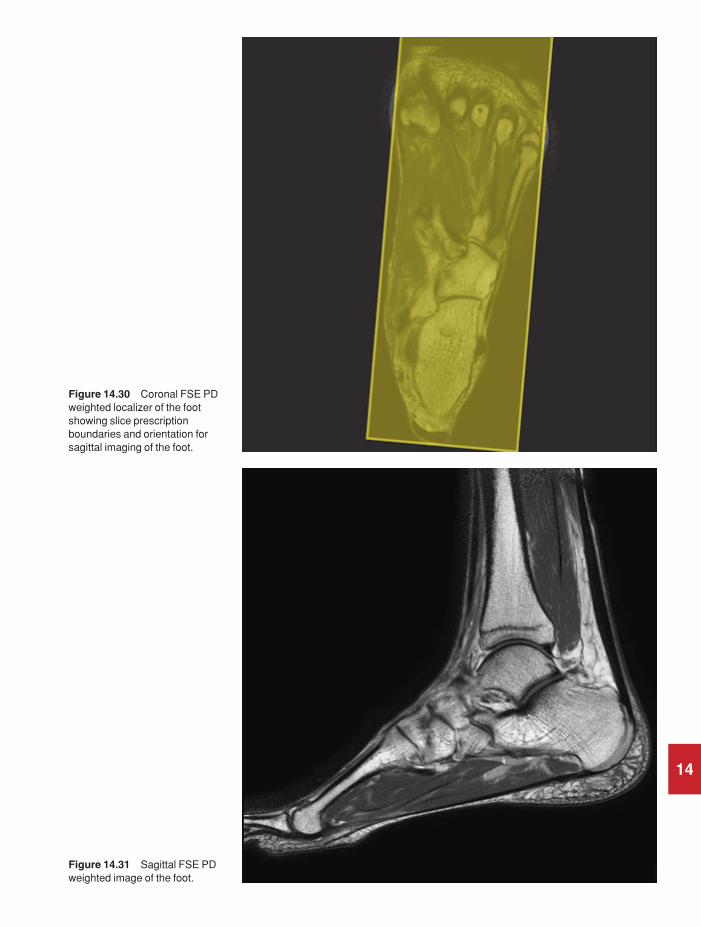
14
Figure 14.30 Coronal FSE PDweighted localizer of the footshowing slice prescriptionboundaries and orientation forsagittal imaging of the foot.
Figure 14.31 Sagittal FSE PDweighted image of the foot.
9781405160858_4_014.qxd 28/05/2008 15:41 Page 339

340 Handbook of MRI Technique
For demonstration of fluid collections, infection, and metatarsal ortarsal fractures.
Additional sequences
Coronal SE T1 or FSE PD/T2 + chemical/spectral presaturation
This scan plane is used in preference to the sagittal where the axial imagesshow significant pathology extending between the metatarsal bones (Fig-ure 14.33).
Sagittal 3D coherent GRE PD/T2*
Acquired as an isotropic dataset, this sequence may be useful to assessanatomy and pathology in any plane. Sagittal slices should include thewhole of the foot from the sole to the distal tibia.
14
Figure 14.32 Sagittal FSE PDweighted image of the foot withchemical presaturation.
9781405160858_4_014.qxd 28/05/2008 15:41 Page 340

Lower limb 341
Image optimization
Technical issues
Foot imaging can be demanding as the foot is small compared with theavailable coils, compromising SNR and resolution. Flexible coils, simplearrays and dedicated coils can compensate for these inherent difficulties.Multiple NEX/NSA are often required to optimize the SNR. Excellentspatial resolution is necessary, especially when examining small structuressuch as the metatarsals and phalanges. Therefore thin slices/gap and fine matrices are required. Additional shimming may be required beforechemical/spectral presaturation sequences.
Artefact problems
There is little flow artefact in this area but it is advisable to place a spatialpresaturation pulse S to the FOV to reduce any flow originating in the distal vessels.
14
Figure 14.33 Sagittal FSE PDweighted image of the footshowing slice prescriptionboundaries and orientation forcoronal imaging of the foot.
9781405160858_4_014.qxd 28/05/2008 15:41 Page 341

342 Handbook of MRI Technique
Patient considerations
Patients are carefully immobilized to reduce motion artefact. The positionof the foot is important for subsequent imaging in orthogonal planes andthe use of pads and tape to support the foot is advised. Due to excessivelyloud gradient noise associated with some sequences, ear plugs mustalways be provided to prevent hearing impairment.
Contrast usage
Contrast is not routinely used in the foot.
14
9781405160858_4_014.qxd 28/05/2008 15:41 Page 342

Lower limb 343
Vascular imaging
Basic anatomy (Figures 14.34 and 14.35)
14
Figure 14.34 Vascular supplyof the right leg.
Common indications
• Evaluation of peripheral vascular disease including stenosis andocclusion.
• Location of run-off vessels or site for arterial bypass of occlusion.• Evaluation of normal venous vasculature (prior to coronary artery
by-pass surgery to determine the optimal graft site).
It is essential to determine the objectives of the examination beforecommencing. For example, if the aim is to survey the entire peripheral
9781405160858_4_014.qxd 28/05/2008 15:41 Page 343

344 Handbook of MRI Technique
vasculature, speed is more important than resolution and multiple FOVs,and sequences, adjusted to display arterial or venous flow, may be appro-priate. However, if the aim is to find a tibial run-off vessel for grafting, theappropriate coils and techniques are different. The technique describedhere is for a full leg arteriogram. Use these key elements and your experi-ence to develop more specialized techniques.
Equipment
• Body phased array/multi-coil array/surface coil/body coil.• Immobilization pads and straps.• Localization markers if required.• Ear plugs.
14
Figure 14.35 Venousdrainage of the right leg.
9781405160858_4_014.qxd 28/05/2008 15:41 Page 344

Lower limb 345
Patient positioning
The patient lies supine on the examination couch with the legs extendedinto the magnet as far as possible. The legs and feet are immobilized usingfoam pads. Several series are acquired at different positions in the legstarting either at the feet or the pelvis. If the vasculature of the feet isimportant, place the feet flat down on to the coil and support this positionwith foam pads under the knees. This ensures that the vessels within thefeet are perpendicular to the axial plane, which is necessary to optimizeimage contrast in TOF-MRA sequences. The patient then extends the legsagain for imaging of the rest of the lower limb vasculature.
The patient is positioned so that the longitudinal light lies in the midlineof the patient, and the horizontal alignment light is centred to the ROI. Itis important to ensure that there is overlap between each series of images.Copper sulphate or oil markers may be taped on to the patient’s lowerlimbs to achieve this or advance the table by 50 mm less than the longit-udinal coverage of each set of sequences. Alternatively, when the first setof images has been acquired return the patient to the landmark position.Move the table to the location of the most superior slice in the imagingstack of the completed series. Mark this position on the patient using tape,and then reposition the coil so that this mark corresponds to the most distal end of the useful area of the coil. Landmark to the new centre of the coil ensuring that there is an overlap of at least 2.5 cm between eachseries. Switch to the body coil for imaging of the femora and pelvis.
Suggested protocol
Coronal incoherent GRE T1
Acts as a localizer if three-plane localization is unavailable. Use a largeFOV to achieve maximum coverage. Medium slices/gap are prescribed oneither side of the vertical alignment light.
P 40 mm to A 40 mm
Axial 2D TOF-MRA
Developing a workable 2D TOF sequence for peripheral MRA is a com-plex task, as many conflicting factors must be taken into account. Mostmanufacturers provide suggested protocols optimized for their operationalmethods and post-processing software. It is probably advisable to startwith these protocols and modify them when you completely understandthe technique rather than start from scratch. Thin overlapping sequen-tially acquired GRE slices are obtained with a travelling spatial presatura-tion band positioned distal to the slice for arteriography, or proximal forvenography. The slices are prescribed through the useful volume of thecoil. It is vital to set the acquisition order to run against the direction of
14
9781405160858_4_014.qxd 28/05/2008 15:41 Page 345

346 Handbook of MRI Technique
blood flow (e.g. from feet to head for leg arteries). Several series are per-formed moving the coil to a new location until the required vasculaturehas been visualized. There must be overlap between each series to avoidmissing important pathology. The images are post-processed to provideoblique and AP views analogous to those collected in X-ray angiography(Figures 14.36–14.38).
Image optimization
Technical issues
The use of a good surface coil enhances the SNR in the lower leg. Whenutilizing the body coil to image the pelvis, the inherent SNR and CNR aregenerally adequate due to the use of a larger FOV. However, because ofthe length of the examination, a coarse matrix is often selected to try to minimize scan times, and resolution sometimes suffers as a result. Toenhance vascular contrast, axial slices are selected so that the direction of flow is perpendicular to the slice. The use of GMN improves vessel
14
Figure 14.36 Sequential CE-MRA of the iliac vesselsshowing an arterial venousmalformation (first pass).
9781405160858_4_014.qxd 28/05/2008 15:41 Page 346

14
Figure 14.37 Sequential CE-MRA of the iliac vesselsshowing an arterial venousmalformation (second pass).
Figure 14.38 Sequential CE-MRA of the iliac vesselsshowing an arterial venousmalformation (third pass).
9781405160858_4_014.qxd 28/05/2008 15:41 Page 347

348 Handbook of MRI Technique
enhancement even further. MT is rarely used as it increases the relativesignal of fat, which then interferes with the post-processed images.Travelling spatial presaturation bands placed between the origin of flowand the imaging stack nullify unwanted signal. These are placed S to theFOV to saturate arterial flow and demonstrate venous anatomy, and I tothe FOV to saturate venous flow and demonstrate arterial anatomy. It isvery important to locate the travelling presaturation bands correctly.Incorrect placement of these saturation bands leads to poor image qualityand perhaps imaging of the wrong vessels.
ECG triggering can enhance the quality of peripheral 2D sequentialTOF-MRA images by eliminating pulsatile flow ghosts and locking acqui-sition to the period of maximum distal flow rate. Flow is tri-phasic inperipheral vessels and will reverse direction through the cardiac phase.
Artefact problems
Motion of the body causes vessels to appear in different locations onsequential axial images and results in stepping in the post-processedimages. Phase ghosting is also occasionally troublesome and is minimizedby reducing the TE or using ECG triggered sequences. Fat signal is ofteninadequately suppressed during TOF-MRA sequences and may interferewith the image. Chemical/spectral presaturation pulses could reduce thisunwanted signal but the time penalty is often unacceptable. Using a TEwhen the fat and water signals are out of phase with each other usuallyadequately suppresses background signal.
Vessel signal may appear to vary regularly along the line of a vessel creating a ‘Venetian blind’ artefact similar to that seen in large slab 3DTOF-MRA. However, in peripheral 2D TOF-MRA the mechanism forthis appearance is quite different. It usually results from the travelling presaturation slab being too close to the scan plane. During the reversal of flow, blood slips back into the saturation band before being imaged.The same effect may result from blood upstream, which was imaged during previous slice acquisitions, flowing back into the current slice loca-tion. It also occurs if the slice acquisition order is not opposite to the direc-tion of flow.
2D TOF-MRA sequences demonstrate reduced vessel signal where thevessel loops backwards or where there is a reversed flow direction. Thislatter situation is common distal to an arterial occlusion. Reverse flow in the distal limb of an occluded artery is provided from collateral supplybut will not be shown with this technique. If the aim of the examination is to visualize the length of an occlusion accurately (e.g. consideration of angioplasty or surgical repair), PC-MRA, which is not flow directionsensitive, should be used.
Patient considerations
As the whole of the vasculature of the lower limb is imaged with an overlap of slices, the examination can take over one hour to perform. It
14
9781405160858_4_014.qxd 28/05/2008 15:41 Page 348

Lower limb 349
is therefore important to make patients as comfortable as possible and to warn them of the length of the study. It is wise to send the patient to the toilet before the examination begins! Ensure that the lower limbs areadequately immobilized, as any motion during the study causes artefact.Due to excessively loud gradient noise associated with some sequences,ear plugs must always be provided to prevent hearing impairment.
Contrast usage
A small dose of contrast (0.25–1 mmol/kg) shortens the T1 of blood andtherefore increases the signal of flowing blood in TOF-MRA sequences.An extension of this technique, dynamic imaging after contrast, is nowwell accepted in examining peripheral vasculature. A range of approachesare under development with the required coils, sequences and coordina-tion measures ranging from those that can be performed with most high-performance systems to those requiring extensive hardware and softwaremodifications.
The technique is directly analogous to X-ray angiography. Extremelyshort TR sequences result in saturation of signal from most tissues exceptthose with very short T1 times, such as the mixture of blood and gado-linium. In this way the vessel lumen is outlined. Short TEs (1–2 ms) areemployed to minimize the effects of flow. Acquisition of the central por-tions of K space, relative to the IV injection, is timed to image the first passof the contrast bolus through the arterial system. Subsequent acquisitionsdisplay the bolus in veins. 3D coronal GRE sequences with very short TRsand TEs are used with high-performance array coils. The coronal planeenables a fast sequence with large coverage, and images are then post-processed. A ‘mask’ scan is often acquired prior to injection for subtrac-tion from the contrast images. This further reduces background signaland is essential if multiple injections are employed. Subtraction of the first pass arterial data from later acquisitions provides better isolation ofthe venous circulation. Timing of the scan to the bolus arrival is critical.This can be achieved with interactive scan initiation via navigator scans,by prior timing of a small dose in conjunction with a single location axialfast sequential scan, or by simple empirical estimation.
14
9781405160858_4_014.qxd 28/05/2008 15:41 Page 349

15
15 Paediatric imaging
350
Introduction
Paediatric MRI can be either an extremely enjoyable challenge or a tech-nical nightmare. The unfamiliar surroundings, tunnel-like nature of themagnet bore, the loud gradient noise and the length of the examinationmay distress some children so that they are unable to cooperate fully withthe examination. Refinements in magnet design such as larger diameter,shorter bores, acoustic dampening and more appealing outer coverings allhelp children and adults into the scanner. However, the commitment andtraining of staff and the culture of the department are probably the mostimportant factors in the success of paediatric imaging. In many institu-tions paediatric patients are considered small adults but, in reality, thisapproach seldom produces quality imaging. This section discusses how to create the right environment for imaging the paediatric patient, thechallenges associated with anaesthesia in the magnetic environment andthe technical issues associated with MR examinations of children.
Creating the right environment
The paediatric population can range from a 400g neonate to an impres-sionable teenager, therefore patient approach must reflect an understand-ing of normal childhood development. The chance of obtaining qualitydiagnostic images is enhanced with accurate patient-specific informationprogrammes. In a non-specialist paediatric unit the normal patient informa-tion documentation (written, verbal or computer based) is usually aimedat the mean socioeconomic level of the patient referral base, and will onlybe of limited use in the paediatric environment. Initially patient informa-tion should be targeted at school-aged children as they are more likely toabsorb information than smaller children.
There are a multitude of effective processes available to assist childrenin coping with this potentially patient-unfriendly environment. This taskis helped by obtaining advice from other health professionals who specializein assisting children cope with a new environment (e.g. play specialists).The most successful programmes involve a combination of environmentand pictorial, symbolic and verbal materials. The first step is to demystify
9781405160858_4_015.qxd 28/05/2008 17:11 Page 350

Paediatric imaging 351
15
Table 15.1 Summary of parameters. The figures given are general and should beadjusted according to the system used (Table 2.1)
Spin echo (SE)short TE min to 30 mslong TE 70 ms +short TR 300–600 mslong TR 2000 ms +
Fast spin echo (FSE)short TE min–20 mslong TE 90 ms +short TR 400–600 mslong TR 4000 ms +short ETL 2–6long ETL 16 +
Inversion recovery (IR) T1short TE min–20 mslong TR 3000 ms +medium TI 200–600 msshort ETL 2–6
STIRlong TE 60 ms +long TR 3000 ms +short TI 100–175 mslong ETL 12–20
FLAIRlong TE 60 ms +long TR 3000 ms +long TI 1700–2200 mslong ETL 12–20
Slice thickness2D thin 2–4 mm
medium 5–6 mmthick 8 mm
3D thin ≤ 1 mmthick ≥ 3 mm
FOVsmall ≤ 18 cmmedium 18–30 cmlarge ≥ 30 cm
NEX/NSAshort ≤ 1medium 2–3multiple ≥ 4
Coherent GRElong TE 15 ms +short TR ≤ 50 msflip angle 20°–40°
Incoherent GREshort TE min–5 msshort TR ≤ 50 msflip angle 20°–40°
Balanced GRETE minimumTR minimumflip angle ≥ 40°
SSFPTE minimumTR 40–50 msflip angle 20°–40°
Slice numbersVolumes small ≤ 32
medium 64large ≥ 128
Matrix (frequency ×× phase)coarse 256 × 128 or 256 × 192medium 256 × 256 or 512 × 256fine 512 × 512very fine ≥ 512 × 512
PC-MRA2D and 3D TE minimum
TR 25–33 msflip angle 30°
VENC venous 20–40 cm/sVENC arterial 60 cm/s
TOF-MRA2D TE minimum
TR 28–45 msflip angle 40°–60°
3D TE minimumTR 25–50 msflip angle 20°–30°
9781405160858_4_015.qxd 28/05/2008 17:11 Page 351

352 Handbook of MRI Technique
the process by allowing patients to view the scanning environment priorto the appointment. This allows staff to make a decision about the level ofsupport that will be necessary to help the patient cope with the examina-tion. In addition, the appointment/patient screening form can be adaptedinto a colouring book with scan related cartoons that the children areencouraged to complete and return at the time of the appointment.
Familiarization with the scanning environment can be accomplished inseveral ways:
• Photographic or symbolic representation of the examination forthe patient and family to read.
• Video: a step-by-step process from patient screening to examina-tion completion.
• Computer based: this is an extension of the video system and, ifavailable on the internet, can be accessed by the patient’s family atany time.
• Involving play specialists or child psychologists to develop a de-sensitization process to help the children cope with their fears and apprehensions (e.g. a full-sized mock MRI unit, complete withscanning sounds, puppets with a small representation of the MRscanner and a calico doll. Children are encouraged to put the dollor puppet through the MRI process in a play setting).
• Develop a patient-friendly environment, e.g. child-related books,toys, videos and computer games in the waiting area greatly reducea child’s anxiety. Remove or cover anaesthetic equipment in thescan room. Shield certain patients from view (an intubated ICUpatient does not breed confidence).
• Make the patient as comfortable as possible for the procedure and,importantly, talk to the child during the examination.
• Encourage them to bring a soft toy (MRI safe) to hold during theexamination.
• Audio and video projection systems are available to entertain thepatient during the procedure. Encourage the patient to bring theirown tape or CD to listen to.
• Encourage a parent to accompany the child during the examination.(Do not forget to screen the parent.)
Finally, verbal reinforcement is probably the area that receives the leastattention but has the greatest potential to help a patient get through anexamination. This applies equally to the adult environment. The patient’sinitial impression will either create or break down barriers. Therefore:
• Talk to your patient, not at them.• Bring yourself down to their level; look them in the face.• Talk to them using terms that they can comprehend.• Be confident in yourself; if you seem hesitant patients can sense this.• Be friendly and talk about something that they seem interested in
(sport, videos, computer games, latest music sensation, school, holi-days, etc.). Develop a rapport.
15
9781405160858_4_015.qxd 28/05/2008 17:11 Page 352

Paediatric imaging 353
• Tell them everything about the examination process; do not lie.• Give positive reinforcement during all processes in the examination.
When examining a child, the process will inevitably involve one or morefamily member; therefore, the technologist must be prepared to explainthe examination process to them. Listed below are the most commonareas of concern that parents express about the MRI examination.
• Does the scan use radiation?• What are the side effects of MRI?• My child has had numerous other investigations, why do they need
a MRI?• Why do they have to hold still for so long?• Why do they need an injection of contrast?• What are the side effects of contrast?• Can they continue their medication prior to the MRI?• What are the fasting instructions for sedation/anaesthetic cases?• Why do we have to complete such a long screening process?• I am not having the scan, why do I need to complete the screening
questionnaire?
When a child has already had numerous investigations and the role ofMRI is to define the pathological process further, there can be a great dealof parental anxiety which can, if not handled correctly, have a detrimentaleffect on the child’s cooperation. Your unit will be expected to have poli-cies in place to deal with this situation if it arises. A parent who hasconfidence in the MRI staff can be a worthy ally in helping their childcomplete the examination.
Sedation and anaesthesia
Patients who are too young or too ill to cooperate will require some formof therapy to help them complete the MRI examination. Intervention ofthis kind requires careful consideration of the facilities available for seda-tion or anaesthesia. If your unit does perform these type of examinations,they must have policies in place to deal with the peculiarities associatedwith these types of examinations.
The primary goals of sedation or anaesthesia are:
• To control patient behaviour, especially movement.• To minimize psychological disturbances and distress.
Staff considerations
The number of staff and the facilities available vary considerably. Somecentres have a full nursing staff, admitting area and recovery room, whilstothers may have none of the above. In addition, units attached to hospi-tals have wards and specialist doctors on site should any emergency arise,whilst isolated facilities have none of these luxuries. It is important that
15
9781405160858_4_015.qxd 28/05/2008 17:11 Page 353

354 Handbook of MRI Technique
the unit’s policy towards sedation/general anaesthesia is discussed fullywith the medical staff, and careful plans are made if sedation or anaesthesiais to be carried out in the unit.
There must always be a qualified doctor in the unit when a sedatedpatient is present. This doctor should take full responsibility for thepatient and his or her condition, regardless of whether the doctor author-ized the examination. The responsible physician must be easily locatedand aware that a sedated patient is present in the unit. Doctors on the tele-phone, teaching, or in a meeting are of no use in an emergency! Childrencan deteriorate very quickly and it is essential that time is not wastedlooking for the radiologist or responsible physician.
It is preferable to employ nurses to supervise the sedation process. Thisensures that the responsibility for sedating and monitoring these patientsis undertaken appropriately, permitting the radiographer/MR technolo-gist and administrative staff to perform their duties effectively. However,some units rely on ward nurses or radiographers to monitor patients,especially if the number of sedated patients is small. This is satisfactory as long as the appropriate personnel are trained and the physician alsoparticipates. All staff within the unit must be aware of the cardiacarrest/medical emergency procedure and should be regularly trained incardiopulmonary resuscitation. Medical personnel should familiarizethemselves on a regular basis with the emergency trolley, its equipmentand drugs. Cardiac arrest teams must be fully aware of the location of theMR unit and be familiar with magnetic safety.
Facilities
If sedation is to be undertaken, there is ideally a quiet area away from themain waiting room where patients can recover undisturbed. However,this room must not be remote from the rest of the unit or personnel in casean emergency arises, and should contain a telephone or other means ofcommunication. The parents are usually allowed to sit with their childduring the recovery process so that the child is not alarmed when he or sheawakes. This room is also useful for keeping the child in a quiet environ-ment whilst the sedation takes effect. It is unreasonable to expect a childto fall asleep when telephones are ringing and people and patients arepassing through the waiting area. If general anaesthesia is performed,there should be a separate anaesthetic room so that patients can be anaes-thetized separately from recovering patients.
Equipment
An anaesthetic induction room adjacent to the MR system can be fullyequipped with conventional apparatus and obviates the need for expensivealterations. It also allows other patients to be examined whilst anaestheticinduction is performed. There must be a fully equipped emergency trolleyin this room that is checked regularly by the unit nurse, anaesthetic nurse,or other responsible party, on a weekly basis. The stocks of drugs used for
15
9781405160858_4_015.qxd 28/05/2008 17:11 Page 354
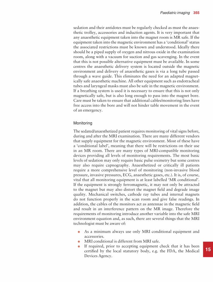
Paediatric imaging 355
sedation and their antidotes must be regularly checked as must the anaes-thetic trolley, accessories and induction agents. It is very important thatany anaesthetic equipment taken into the magnet room is MR safe. If theequipment taken into the magnetic environment has a ‘conditional’ statusthe associated restrictions must be known and understood. Ideally thereshould be a piped supply of oxygen and nitrous oxide in the examinationroom, along with a vacuum for suction and gas scavenging. In the eventthat this is not possible alternative equipment must be available. In somecentres the anaesthetic delivery system is located outside the magneticenvironment and delivery of anaesthetic gases is via a long tube passedthrough a wave guide. This eliminates the need for an adapted magnet-ically safe anaesthetic machine. All other equipment such as endotrachealtubes and laryngeal masks must also be safe in the magnetic environment.If a breathing system is used it is necessary to ensure that this is not onlymagnetically safe, but is also long enough to pass into the magnet bore.Care must be taken to ensure that additional cables/monitoring lines havefree access into the bore and will not hinder table movement in the eventof an emergency.
Monitoring
The sedated/anaesthetized patient requires monitoring of vital signs before,during and after the MRI examination. There are many different vendorsthat supply equipment for the magnetic environment. Most of these havea ‘conditional label’, meaning that there will be restrictions on their use in an MR room. There are many types of MRI-compatible monitoringdevices providing all levels of monitoring requirements. The most basiclevels of sedation may only require basic pulse oximetry but some centresmay also require capnography. Anaesthetized or critically ill patientsrequire a more comprehensive level of monitoring (non-invasive bloodpressure, invasive pressures, ECG, anaesthetic gases, etc.). It is, of course,vital that all monitoring equipment is at least labelled ‘MR conditional’. If the equipment is strongly ferromagnetic, it may not only be attracted to the magnet but may also distort the magnet field and degrade imagequality. Mechanical switches, cathode ray tubes and internal magnets do not function properly in the scan room and give false readings. In addition, the cables of the monitors act as antennae in the magnetic fieldand result in an interference pattern on the MR image. Therefore therequirements of monitoring introduce another variable into the safe MRIenvironment equation and, as such, there are several things that the MRItechnologist must be aware of:
• As a minimum always use only MRI conditional equipment andaccessories.
• MRI conditional is different from MRI safe.• If required, prior to accepting equipment check that it has been
certified by the local statutory body, e.g. the FDA, the MedicalDevices Agency.
15
9781405160858_4_015.qxd 28/05/2008 17:11 Page 355

356 Handbook of MRI Technique
• Check that all components match the model number listed by themanufacturer as MRI conditional or safe.
• Be aware of any MR conditional requirements of equipment takeninto the scan room.
• Get the system electrically tested by the local biomedical unit.• Use hand magnets to test various components (casing, stand, etc.)
to see if they are ferromagnetic.• On phantom or volunteer studies test individual sequences for
artefacts.• Read the manual for safe operating technique.• Run in-service lectures so that the different levels of staff under-
stand the basic functions of the system.• Regularly inspect cables for signs of damage.• Research carefully before buying.• If you suspect any component of the monitoring system has caused
an injury to the patient immediately remove it from service. Con-tact the manufacturer/service agent to get the problem rectified.
Remember: MRI conditional is different from MRI safe
Placing equipment outside the room and passing monitoring cables throughan RF filter within the penetration panel may diminish image quality andinduce artefacts. Fibre-optic cables will reduce interference and a liquid-crystal display, instead of a cathode-ray tube, eliminates the distortionproblem of conventional ECG monitors. When purchasing MR monitor-ing equipment be aware of the conditional aspects of the equipment.Some systems are purpose built, whereas others may involve conventionalequipment enclosed in a Faraday shield. It should be noted that manyMRI vendors specifically prohibit the use of the gating equipment formonitoring purposes during sedation/general anaesthesia. They state thatthe monitor is not designed for accuracy under these circumstances and istherefore unreliable. Check the manufacturers’ specifications for details.
Patient preparation
The patient admission policy of the unit often varies according to facilitiesavailable and whether sedation or general anaesthesia is to be adminis-tered. If the child is to be sedated in the unit, he or she must arrive at leasttwo hours before the examination. This allows for all the admitting pro-cedures to be completed, for sedation to be given, and for it to take effect.Some facilities attached to a hospital may wish to admit the child on to aday ward. Although this alleviates the problem of children and parentscluttering up the waiting area, it entails the cooperation of ward nursesand porters. Large units, which have separate waiting areas, sedation roomsand recovery areas incorporated into the building, often find admittanceto a ward unnecessary.
Each child has a full medical assessment by a paediatrician, paediatricradiologist, sedation nurse or anaesthetist before the examination. This
15
9781405160858_4_015.qxd 28/05/2008 17:11 Page 356

Paediatric imaging 357
includes allergies to medicines, current medication, previous and existingmedical problems and a note of the patient’s vital signs. All tests, such asblood tests and X-rays, are completed and the results accepted as satisfac-tory by the admitting doctor. The drugs required for the sedation/generalanaesthesia are written in the notes by the admitting doctor or anaesthetist,and consent for sedation or anaesthesia acquired from the parents. Oncethe child arrives at the centre the vital signs are checked and recorded. Thechild’s clothing should be checked for examination suitability and, if necessary, they should be changed into hospital pyjamas. Gowns may beused but pyjamas are likely to be warmer. A full magnetic screening of theparents, child and accompanying nurse must be carried out.
It is the responsibility of the MRI unit and the referring physician toensure that adequate pre-examination fasting has occurred. This differsdepending upon the age of the patient involved. The fasting schedulegiven to the parents or ward staff must contain clear and concise instruc-tions, information about continuing any medications and the phone num-ber of a contact person for clarification. It should be noted that in somecentres fasting instructions may vary depending upon the type of sedationadministered. An example of a fasting schedule is listed below:
IV and gaseous sedation agents
• 0–12 months: Patient may have solids and milk up to 4 hours(breast milk 2 hours) before the scheduled examination. Clearfluids may be given 2 hours before the examination.
• 2 months–4 years: Patient may have solids and milk up to 4 hours(breast milk 3 hours) before the scheduled examination. Clearfluids may be given 2 hours before the examination.
• 4 years plus: Patient may have solids and milk up to 6 hours beforethe scheduled examination. Clear fluids may be given 2 hours be-fore the examination.
Oral sedation (all ages)
• 2 hours solids and fluids.
Some centres elect to perform MRI examinations on small babies byfeeding them and swaddling them so that they feel warm and secure, how-ever there is a chance of vomiting and aspiration so the infant must becarefully watched at all times.
Venous access is required for some forms of sedation and most generalanaesthetics. In addition it is required if contrast is used. Many childrenand adults are frightened of or apprehensive about injections. An easyapproach is to use vasodilating topical local anaesthetic creams which, insome circumstances, may be vasoconstrictive, and should be removed atleast 10 minutes before cannulation. In cases where there is uncertainty asto whether contrast agents are required, use topical anaesthetic creamanyway. It is easier to remove the cream if an injection is not required
15
9781405160858_4_015.qxd 28/05/2008 17:11 Page 357
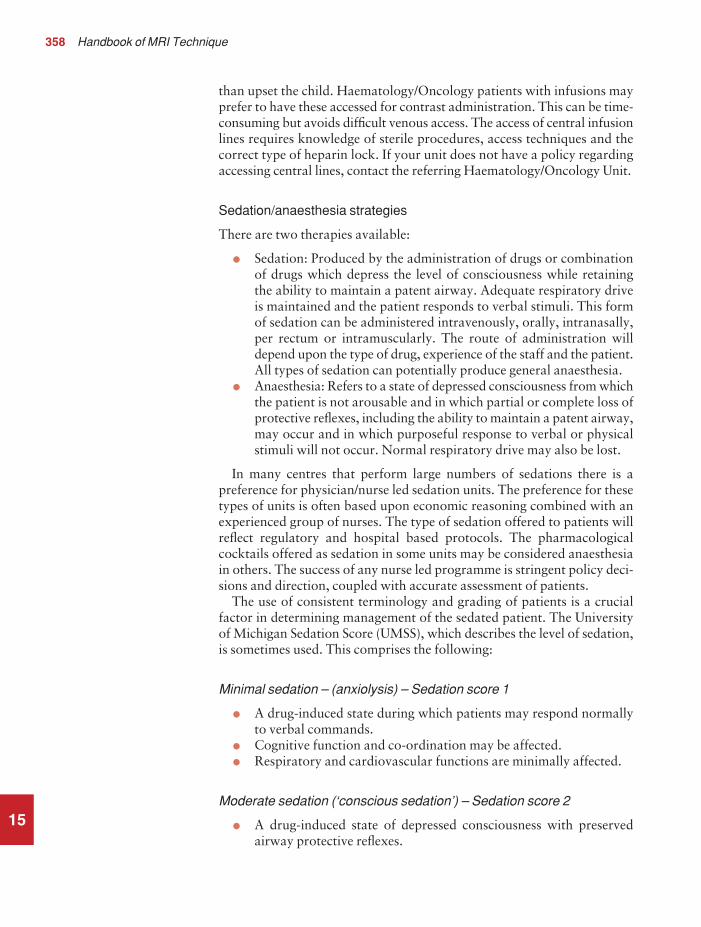
358 Handbook of MRI Technique
than upset the child. Haematology/Oncology patients with infusions mayprefer to have these accessed for contrast administration. This can be time-consuming but avoids difficult venous access. The access of central infusionlines requires knowledge of sterile procedures, access techniques and thecorrect type of heparin lock. If your unit does not have a policy regardingaccessing central lines, contact the referring Haematology/Oncology Unit.
Sedation/anaesthesia strategies
There are two therapies available:
• Sedation: Produced by the administration of drugs or combinationof drugs which depress the level of consciousness while retainingthe ability to maintain a patent airway. Adequate respiratory driveis maintained and the patient responds to verbal stimuli. This formof sedation can be administered intravenously, orally, intranasally,per rectum or intramuscularly. The route of administration willdepend upon the type of drug, experience of the staff and the patient.All types of sedation can potentially produce general anaesthesia.
• Anaesthesia: Refers to a state of depressed consciousness from whichthe patient is not arousable and in which partial or complete loss ofprotective reflexes, including the ability to maintain a patent airway,may occur and in which purposeful response to verbal or physicalstimuli will not occur. Normal respiratory drive may also be lost.
In many centres that perform large numbers of sedations there is a preference for physician/nurse led sedation units. The preference for thesetypes of units is often based upon economic reasoning combined with anexperienced group of nurses. The type of sedation offered to patients willreflect regulatory and hospital based protocols. The pharmacologicalcocktails offered as sedation in some units may be considered anaesthesiain others. The success of any nurse led programme is stringent policy deci-sions and direction, coupled with accurate assessment of patients.
The use of consistent terminology and grading of patients is a crucialfactor in determining management of the sedated patient. The Universityof Michigan Sedation Score (UMSS), which describes the level of sedation,is sometimes used. This comprises the following:
Minimal sedation – (anxiolysis) – Sedation score 1
• A drug-induced state during which patients may respond normallyto verbal commands.
• Cognitive function and co-ordination may be affected.• Respiratory and cardiovascular functions are minimally affected.
Moderate sedation (‘conscious sedation’) – Sedation score 2
• A drug-induced state of depressed consciousness with preservedairway protective reflexes.
15
9781405160858_4_015.qxd 28/05/2008 17:11 Page 358

Paediatric imaging 359
• Patients may be somnolent/sleeping but easily aroused with lighttactile stimulation or verbal command.
It is possible for patients to progress from a state of moderate sedationinto a deep sedation/obtundation very easily.
Deep sedation – Sedation score 3
• A drug-induced state of depressed consciousness from which thepatient is not easily roused.
• Sedation may be accompanied by partial or complete loss of pro-tective airway reflexes.
• Patients are usually unable to respond purposefully to physical orverbal stimulation.
There are some contraindications to sedation techniques and some ofthese are listed below:
• Increased risk of delayed gastric emptying or vomiting.• Significant respiratory disease.• Abnormal conscious state or raised ICP.• Previous adverse event with sedation.• Acute systemic illness.• Patient currently receiving opioids or other sedative agents.• Age related requirements – oral vs. IV.
The safe conduct of anaesthesia requires a trained anaesthetist and dedicated assistant, as well as specialist equipment, which may requireexpensive modification to be magnetically safe. The anaesthetist andother anaesthetic staff must be experienced and knowledgeable of thehazards of the magnetic field. It is preferable that they attend the unit on aregular basis so that MR practitioners do not have repeatedly to educateand screen new anaesthetists. In the interests of magnetic safety, anaesthe-sia may be induced in a separate room and once the patient’s airway issecured, he or she is then transferred to the scan room. Alternatively theycan be anaesthetized in the scan room under strict supervision.
It is important that a minimum amount of equipment is taken into the scan room. All anaesthetic equipment deemed MRI safe/conditionalshould have a distinctive colour coding or be labelling to reduce the possibilities of unsafe accessories entering the vicinity of the magnet environment. In units performing a large number of anaesthetics it is possible, once strict guidelines have been established, to perform minorprocedures such as lumbar punctures or skin biopsies within the magnetenvironment.
Always double check the patient, anaesthetist and anaesthetic acces-sories for ferromagnetic objects before entering the magnetic field.
The anaesthetist may choose to maintain anaesthesia with inhalationagents that then require scavenging to the atmosphere, or by IV anaestheticsthat require infusion pumps. These pumps not only present a projectile
15
9781405160858_4_015.qxd 28/05/2008 17:11 Page 359

360 Handbook of MRI Technique
risk and may induce RF artefacts, but the unit may malfunction in themagnetic field. To avoid problems of this nature, infusion pumps areplaced as far away from the magnet as possible, or the agents are infusedby hand. The patient is either allowed to breathe spontaneously or theyhave their lungs mechanically ventilated. Breathing systems are requiredthat are long enough to pass into the magnet bore. The airway is securedeither by endotracheal intubation or by a laryngeal mask. The most com-mon method is probably the laryngeal mask technique but this has severaldrawbacks as far as the MR examination is concerned. A large amount ofair is often used to inflate the mask, which creates a susceptibility interfaceespecially in GRE, chemical/spectral presaturation and EPI sequences. Inaddition, the valve used to maintain the cuff may contain a small spring,which can fall into the imaging volume, causing an artefact. However,these problems can be overcome by consulting the anaesthetist prior tothe examination.
The type of therapy chosen will depend on many factors including:
• Age and size of the patient.• Type of MRI to be obtained.• Patient’s physical condition.• Availability of anaesthetic staff.• Support personnel in the event of an unanticipated clinical event.• Monitoring and anaesthetic equipment.• Location of the MRI unit (outpatient or hospital facility).
There are advantages and disadvantages of both sedation and anaes-thesia. The decision to use one or the other is made by the referring clini-cian, radiologist and anaesthetist. With the increased popularity of manybreath-hold techniques for cardiac and abdominal imaging, the need for respiratory control may expand. The following should be taken intoconsideration.
Advantages of anaesthesia over sedation
• The time that unconsciousness is achieved is predictable so there islittle disruption to the schedule.
• It is safe to assume that the patient will remain asleep during theentire examination and not wake up due to the gradient noise or the sedation wearing off.
• As the anaesthetist usually inserts an IV line, there is access for theadministration of contrast or emergency drugs.
• There is a trained anaesthetist present during the examination andrecovery period should an emergency arise.
• If an endotracheal or laryngeal mask is inserted the airway issecured.
• Patients often wake up faster from a carefully balanced anaestheticthan they do from sedation and so the patient can leave the unitsooner.
15
9781405160858_4_015.qxd 28/05/2008 17:11 Page 360

Paediatric imaging 361
Disadvantages of anaesthesia over sedation
• Requires an anaesthetist and anaesthetic nurse and is thereforecostly.
• Requires magnetically safe anaesthetic equipment and involves alarge capital outlay.
• The extra personnel and equipment increase the likelihood thatthere will be a breach of magnetic safety.
• It may be somewhat disruptive to the schedule, especially if severalchildren are being anaesthetized in one session.
• Depending upon the type of anaesthetic there is an increased risk ofpost-examination vomiting.
• The children make become distressed after a light general anaesthe-sia as they become confused and disorientated when awakening.
Neonates and babies under 3 monthsThe younger the child, the greater is the chance that an unsedated exam-ination will be successful. Particular care is necessary to keep these babieswarm, as the bore fan and cool examination room can cause significanthypothermia. Swaddling the child in blankets usually provides sufficientinsulation and also acts as a very effective immobilization device. Youngbabies and small children dissipate the majority of body heat from theirheads. Ensure that the room and bore lights are dimmed prior to thepatient’s arrival, and that all personnel keep as quiet as possible duringthe examination. The child is monitored both with specific monitoringdevices and by a parent, doctor, or nurse, present in the room. Particularlysick neonates require closer supervision. If an unsedated examination isunsuccessful, the baby is sedated as for older children.
Babies and children 6 months to 5 yearsChildren exhibit a variety of responses to sedation according to age, type of sedation used and the temperament of the child. Mentally dis-turbed and behaviourally challenged children are especially difficult tosedate effectively. Various sedation regimes have been described utilizingchloral hydrate (+/−liquid paracetamol), diazepam, pentobarbital or theToronto mixture. Adult patients often respond well to IV increments of ashort-acting benzodiazepine such as midazolam, which can be titrated tothe desired effect. It is imperative that all sedated patients are monitoredthroughout the examination and recovery period. Oxygen should be pro-vided via a face mask or nasal cannula. If sedation is ineffective, the dosesof the above drugs can be increased under the guidance of a physician;however, as sedation is not always successful in this age group, anaesthe-sia is often required.
Children over 5 yearsChildren of this age can often be scanned without sedation. This dependslargely on their age and level of maturity. The parents are very important
15
9781405160858_4_015.qxd 28/05/2008 17:11 Page 361

362 Handbook of MRI Technique
determining factors on the success of an unsedated examination. In someinstances, calm parents are just as effective as a drug. However, there aresome circumstances when sedation or anaesthesia is required.
Recovery
All patients who have been sedated or anaesthetized must have recoveredfully before they are allowed to return to their home or to the ward. Apatient is usually considered recovered if they are:
• Awake and orientated.• Exhibiting stable vital signs for at least 1 hour after the end of the
administration of anaesthesia.• Able to tolerate oral fluids before leaving the unit or ward.• In the company of a responsible adult.• Do not have to operate machinery within 24 hours of the examina-
tion (adults only).
The parents are given easily interpretable verbal and written instruc-tions to watch the child carefully and indications of typical behaviour inthe next 24 hours. Contact telephone numbers in case of an emergencymust be included in the instructions.
Emergencies
In the event of a patient requiring resuscitation during an examination(whether they have been anaesthetized or not), the cardiac arrest team issummoned. The patient should then be immediately evacuated out of themagnetic environment to the anaesthetic area. In this way emergencyequipment is readily available and there is less risk of ferromagnetic itemsbeing inadvertently taken into the examination room. This manoeuvrealso eliminates the necessity of screening all the personnel on the cardiacarrest team for magnetic safety. In addition, the unit staff should be regularly trained on the appropriate evacuation procedure and cardiopul-monary resuscitation.
Departmental policies
Taking on the responsibility of sedating or anaesthetizing patients requiresdepartmental or unit-based policies to ensure as smooth a process as possible. These policies must include all aspects of the examination fromscheduling of the patient to post-MRI follow-up. The key areas thatshould be addressed are:
• Patient selection criteria.• Selection criteria for staff working with sedated or anaesthetized
patients.• Scheduling.• Patient information regarding fasting instructions.
15
9781405160858_4_015.qxd 28/05/2008 17:11 Page 362

Paediatric imaging 363
• Informed consent.• Current medication.• Pre-examination physicals.• Type of therapy required.• Reference to who can order and administer sedation/anaesthesia.• Examination monitoring based on minimum accepted standards of
anaesthetic department or association.• Post-examination recovery period; essentials of vital-sign
documentation.• Unit follow up post examination• Discharge information to parents.• Unit follow-up and evaluation.• Clear defined department protocols and procedures.
The MRI examination
Like adults, the majority of examinations in the paediatric environmentare based on the neuroaxis (head and spine). In older children the exam-ination technique is the same as for adults, but their concentration spanmay differ so later scans may exhibit some form of movement artefact.The greatest difference lies within the smaller, sedated or anaesthetizedgroup where the examination may be terminated due to the patient wak-ing up or to a change in the medical condition. As with any MRI examina-tion, it is necessary to obtain the critical, high diagnostic yield scans earlywithin the examination. One of the most common errors in performingpaediatric examinations is to increase spatial resolution by reducing theFOV and slice thickness, without making the necessary adjustments tosignal averaging to maintain SNR. In some clinical situations there may a problem with exceeding the currently acceptable SAR limits. This ismore of an issue when transmitting with the body coil and using large RFdeposition sequences.
The equation for SAR is:
SAR is proportional to B02 α2 D,
where B = static magnetic field, α = flip angle and D = duty cycle.The duty cycle relates to the number of RF pulses per TR period and
includes fat suppression, magnetization transfer, presaturation pulses and ETL.
As many paediatric patients are sedated, physiological changes mayaffect image quality, especially in the brain. For example, the PCO2 maybecome elevated (this is more pronounced in anaesthesia with or withoutvolatile anaesthetic agents where respiratory support is not provided)leading to several noticeable changes in image contrast and quality. First,even a small increase in PCO2 accentuates pulsatile artefacts from largeCSF-filled structures, especially around the third ventricle. Secondly, anincrease in PCO2 causes small intracranial vessels to dilate, which canpotentially improve the quality of intracranial MRA. This phenomenon
15
9781405160858_4_015.qxd 28/05/2008 17:11 Page 363

364 Handbook of MRI Technique
permits the use of larger flip angles and shorter TRs to produce angio-grams with good SNR and improved conspicuity of smaller peripheralvessels. Newer image reconstruction techniques, such as parallel imaging,may not be as effective in the paediatric environment due to the anticip-ated reduction in SNR. Small FOV and higher through-plane resolutionmay preclude the use of parallel imaging.
Smaller coils can often be used, thereby increasing local SNR. Forexample, a small child’s body can be examined in the head coil rather thanthe body coil. Surface coils often give sufficient signal coverage and depthto scan large areas. If examining the torso, it is wise to raise the child andcoil using pads so that the area under examination is nearer to isocentre.This not only improves SNR but also enables the implementation of arectangular/asymmetric FOV for imaging the spine, chest, abdomen, andpelvis. However, with more flexible off-centre capabilities and rectangu-lar/asymmetric FOV options, this strategy may not be necessary. Contrastcharacteristics in children are similar to those in adults and thereforeparameters such as TR, TE and flip angle are comparable. The mainexception to this is in the neonatal brain, where myelination patterns andincreased water content necessitate the use of a much higher TR in CSEsequences than adults (see Brain, below).
It is essential that a sedated patient be as comfortable as possible duringthe examination and care should be taken to ensure that adequatepadding is used around pressure points. This is particularly important incases of myelomeningocele and sacrococcygeal teratoma. A sedatedpatient can quickly lose body heat so it is essential to provide adequatethermal support. A small baby can lose up to 50% of its total body heatfrom the head so take particular care in adequately covering this. In providing blankets or other coverings to maintain temperature, rememberto use material that is static resistant. Ear protection is still a vital com-ponent of patient care and, due to the variable size of children, the rangeof hearing protection material used may need to be revised. A combina-tion of mouldable disposable ear plugs and normal headphones usuallysuffices.
Common indications for paediatric imaging are:
Brain
• Congenital developmental anomalies (Chiari, heterotopia, corticalmalformations, neuronal migration).
• Metabolic (Leigh’s disease, Wilson’s disease, lipid storage diseases).• White-matter diseases (dysmyelination, demyelination).• Hydrocephalus.• Tumours.• Neurofibromatosis, tuberous sclerosis.• Epilepsy (mesial temporal sclerosis).• Infective processes (abscess).• Destructive processes (encephalomalacia).• Trauma.
15
9781405160858_4_015.qxd 28/05/2008 17:11 Page 364

Paediatric imaging 365
MRA
• Congenital vascular anomalies.• AVM – pre- and post-embolization.• Infarct/ stroke.• Vasculopathy.• Pre-surgical tumour resection.• Venous thrombosis.
Spine
• Congenital lesions (Chiari, myelomeningocele, lipoma, tethering,diastematomyelia).
• Scoliosis.• Canal stenosis typically achondroplasia.• Tumours (intramedullary, extramedullary).• Trauma.• Infective (discitis, osteomyelitis).• Inflammatory (transverse myelitis, Guillain-Barré).• Degenerative (disc disease, spondylolisthesis).• Syringomyelia, hydromyelia.• Brachial plexus, obstetric injury.
Musculoskeletal
• Congenital cartilage anomalies such as discoid meniscus.• Trauma, sporting injuries.• Avascular necrosis/osteochondritis dissecans.• Growth plate anomalies.• Intra-articular foreign bodies.• Tumours (osteosarcoma, Ewing’s sarcoma, rhabdomyosarcoma).• Evaluation of congenital dislocation of the hips.• Lymphatic or vascular malformations.
Body and cardiac
• Diagnosis of undescended testicle.• Congenital abnormalities of the reproductive system.• Imperforate anus, developmental pelvic anomalies (bladder
exstrophy).• Evaluation of congenital cardiac and great vessel anomalies.• Tumours (Wilms’, hepatoblastoma, cardiac).• Liver (including MRCP) and renal (including MRU and functional
studies).• Vascular abnormalities.• Liver and cardiac iron studies.
15
9781405160858_4_015.qxd 28/05/2008 17:11 Page 365

366 Handbook of MRI Technique
Brain imaging
Imaging protocols must make provision for imaging the immature andmature paediatric brain. As the brain matures there are quite noticeablechanges in contrast on both T1 and T2 weighted images, as comparedwith that of the mature brain. These changes reflect the relative concen-trations of free water and compounds responsible for myelination. Inmost texts the brain is considered mature by 18–20 months. Before thisT1 and T2 weighted images play differing roles in the assessment of brainmaturation. In the first few months of life, T1 weighted images are import-ant to determine normal myelination, whereas later T2 weighted imagesare more sensitive. Prior to full maturation it is necessary to use longerTRs and TEs to obtain good T2 weighting. The increase in TE will alsonecessitate a corresponding change in TI and TR in FLAIR FSE sequences.
Brain protocols in the adult population have been comprehensively discussed earlier in this book but paediatric considerations are outlinedbelow. It is impossible to use a single imaging protocol to address theplethora of paediatric clinical presentations. All the suggestions givenbelow depend upon your system’s hardware and software (prospectiveand retrospective reconstruction capabilities) and the individual prefer-ences of your reporting and referring clinicians. In general, however, theprotocols listed should cover most eventualities.
Axial/coronal FSE T2 (Figures 15.1 and 15.2)
It is imperative that imaging of the developing brain is not restricted to asingle imaging plane. Recent advances in time efficient 3D T2 sequencesoffer the ability to obtain high in-plane resolution with isotropic voxels inunder 6 minutes. In most institutions FSE techniques are considered theoptimal sequences, obtaining good quality T2 weighted images in a shortscan time. Long ETLs and TRs combined with fine matrices are required.Recent advantages in RF and gradient technology have enabled moreflexible combinations of long ETLs and echo spacing, which if usedappropriately can have dramatic effects on the ability to visualize tissueswith a short T2 and small lesions (see Pulse sequences in Part 1). In casesof suspected demyelination or acute disseminating encephalomyelitis(ADEM) it is essential to perform a T2 weighted sequence to evaluate thecorpus callosum.
FLAIR FSE (Figures 15.3 and 15.4)
The advent and further refinement of these sequences has greatly enhancedthe conspicuity of many intracranial lesions. In some pathological processessuch as neurofibromatosis, tuberous sclerosis and medul-loblastoma theaddition of water excitation or fat suppression to the FLAIR sequence has greatly increased its diagnostic sensitivity negating the use of protondensity or balanced images. The diagnostic sensitivity of FLAIR may alsobe improved with high resolution isotropic 3D data sets.
15
9781405160858_4_015.qxd 28/05/2008 17:11 Page 366

15
Figure 15.1 Axial FSE T2weighted image in a 4-month-old child. Polymicrogyria andgliosis are clearly seen and mayrepresent an hypoxic incident.
Figure 15.2 Coronal FSE T2weighted image demonstratinga double cortex in a child withdevelopmental delay.
9781405160858_4_015.qxd 28/05/2008 17:12 Page 367

15
Figure 15.3 Axial FLAIRsusceptibility weighted image of the brain demonstratingmetastases from a highlymalignant sarcoma.
Figure 15.4 Axial 3D waterexcitation FLAIR image of thesame patient in Figure 15.3.
9781405160858_4_015.qxd 28/05/2008 17:12 Page 368

Paediatric imaging 369
15
2D/3D FSE/incoherent (spoiled) GRE +/− IR T1 (Figure 15.5)
The choice of sequence for T1 weighted imaging depends on the requiredfield strength, resolution and image contrast. One option is to use 3D fastGRE with an inversion pulse (e.g. MP RAGE) as it provides a balancebetween image contrast, spatial resolution, flexibility, durability and scantime. If 2D imaging is preferred, it is essential to obtain sagittal images forposterior fossa pathologies. Otherwise either axial and/or coronal imag-ing is usually preferable. Historically, T1 weighted SE sequences havebeen conventionally utilized but with refinements in FSE, such as shorterecho spacing and higher receive bandwidths, this sequence is now con-sidered a more time-efficient alternative.
Post-contrast imaging should be obtained in a minimum of two planesand one of these may include the use of MT. The literature contains manyreferences relating to improved lesion conspicuity using MT. The detec-tion of subtle, small pathologies such as metastases and meningeal diseaseare enhanced using MT. Some normal anatomical structures can exhibithyperintensity on MT sequences, therefore it is often wise to obtain a pre-contrast MT as well as a post-contrast series. The addition of a MT to thesequence reduces the amount of slices available per TR, and it may be
Figure 15.5 3D incoherent(spoiled) GRE reformatted in the axial plane demonstratingtransmantle dysplasia.
9781405160858_4_015.qxd 28/05/2008 17:12 Page 369

370 Handbook of MRI Technique
15
preferable to obtain images in two acquisitions using a short TR, thanincrease the TR (and hence reduce T1 weighting) to obtain coverage.Some centres prefer to use a 3D sequence post-contrast acquisition. Thissequence should preferably employ water suppression techniques, thinslice isotropic voxels and, depending upon the imaging coil, parallel imag-ing techniques.
To evaluate the immature brain it is important that the 3D sequenceallows the flexibility to vary the TI or magnetization-prepared time tovisualize physiological changes within the brain. This requirement tomodify the inversion time is more critical in sequences that employ centricfilling of k-space. As the brain matures, shorter TIs are required. Althoughthe appropriate values will depend on field strength, a TI range from 900 ms for newborn infants to 350 ms for matured brains is common.This strategy permits visualization of myelination processes and develop-mental anomalies, even through the transition period when grey andwhite matter have similar signal characteristics on T2. Some sites elect touse a single or dual inversion STIR sequence for this purpose.
Susceptibility weighted imaging/GRE/SE-EPI sequences (Figures 15.6 and 15.7)
These sequences play an important role in trauma, metabolic disordersand perinatal infections where the visualization of haemorrhage/calciumis required. With the advent of sequences using multiple 180° RF pulses,the ability to detect calcium/haemorrhage is somewhat compromised atlow and mid-field (0.35–1.5 T) so it is necessary to include a sequence thatemphasizes these appearances in clinically suspected cases. Historically,this has been achieved using a conventional GRE sequence but it is pos-sible to obtain higher resolution and faster scans by using purposelydesigned susceptibility weighted sequences (SWI ) or multi-shot EPI sequ-ences (GRE or SE).
Diffusion
DWI sequences now play an integral role in diagnostic protocols. Theyare commonly performed in cases of suspected infarction, asphyxia,trauma (looking for the sequelae to petechial haemorrhage), cysts (cyst vs.epidermoid) and intracranial tumours (see Pulse sequences in Part 1 andBrain under Head and neck in Part 2). Diffusion tensor imaging (DTI) ortractography sequences are proving useful in cases of congenital/corticalmalformations, tumours and infarction. It has been postulated that DTImay have a pivotal role in the evaluation of tumour seeding along whitematter tracts in invasive tumours such as glioblastoma multiforme. DWIand DTI offer a quantitative approach to the evaluation of lesions involvingthe brain, spinal cord and abdominal organs by using apparent diffusioncoefficients, fractional and regional anisotropy. Parallel imaging is routinelyused in DWI/DTI especially at higher fields to reduce the geometric distor-tions caused by magnetic susceptibility.
9781405160858_4_015.qxd 28/05/2008 17:12 Page 370

15
Figure 15.7 Axial SE-EPIdemonstrating chronichaemorrhage.
Figure 15.6 Coronal T2 FSE (left) and GRE-EPI (right) showing subtle earlycalcification (arrow). Note howwell this abnormality is seen onthe GRE-EPI image comparedto the FSE, due to susceptibilityeffects.
9781405160858_4_015.qxd 28/05/2008 17:12 Page 371

372 Handbook of MRI Technique
15
Epilepsy (Figure 15.8)
Temporal lobe epilepsy (TLE) (complex partial seizures) is probably oneof the most common requests for paediatric brain imaging, and the com-plete evaluation of these patients can be time-consuming. In addition to evaluating the temporal lobes, a standard brain protocol must also beperformed as approximately 30% of lesions presenting as TLE are outsidethe temporal lobes. FLAIR FSE (rather than EPI sequences), in either the coronal or sagittal planes, is necessary to evaluate the hippocampus.EPI sequences produce susceptibility from the petrous bones and, as thin slices are required to achieve adequate resolution in this area, SNR iscompromised.
To evaluate the temporal lobe and hippocampus completely, the exam-ination must include sequences that detect signal changes within the hip-pocampus, atrophy and the internal architecture of the hippocampus. Theslice plane should be orientated perpendicular to the line of the hippocam-pus. IR–FSE, with a medium TI, a short ETL and fine matrices, is a usefulsequence to visualize the internal architecture of the hippocampus. Manysites attempt to gain these types of images using longer ETLs but blurringoften compromises some of the spatial resolution. Isotropic 3D sequences
Figure 15.8 Coronal FSE T2weighted image demonstratingmesial temporal sclerosis(arrow). This is a commoncause of epilepsy.
9781405160858_4_015.qxd 28/05/2008 17:12 Page 372

Paediatric imaging 373
15
are extremely valuable assets when evaluating epilepsy as the images may be reformatted into other orthogonal and oblique orientations. Inaddition, volumetric measurements of the hippocampus and rendered or curved reformats of specific anatomical regions are possible. Thesesequences should be reformatted in a minimum of two planes. The choiceof sequence for the volume is usually an incoherent (spoiled) GRE with orwithout some type of preparation pulse, but some sites are experimentingwith 3D FSE for volumetric studies. Pre-Fourier manipulation techniquesallow high-resolution, short TE images to be obtained in shorter scan times,and further development and refinement of these sequences should lead totheir increased use in the future. Finally, patients that present with seizuresmust have an examination that includes high-resolution sequences (sagittaland coronal) of the hypothalamic region.
Pituitary disease (Figure 15.9)
The main indications for imaging the pituitary/optic chiasm in paediatricsare failure of the pituitary gland to develop normally (e.g. ectopic posteriorpituitary), hamartomas, tumours (craniopharyngiomas, astrocytomas,gliomas) and neurofibromatosis. In children under 8 months the most
Figure 15.9 Sagittal (left) andcoronal (right) T1 weightedimages after contrast showingan ectopic posterior pituitary.
9781405160858_4_015.qxd 28/05/2008 17:12 Page 373

374 Handbook of MRI Technique
15
common intracranial tumours are astrocytomas arising from the opticchiasm. Investigation of developmental anomalies must include T1 weightedimages in the sagittal and coronal planes. The choice of sequence dependsupon the quality of the head coil and range of sequences available. Ideally,images are obtained with a small FOV and thin contiguous slices (minimumslice thickness 2.5 mm). In SE it is necessary to use multiple NEX/NSAand a narrow receive bandwidth to obtain sufficient SNR. These sequencesare, therefore, time-consuming and an incoherent (spoiled) GRE volumesequence using an isotropic dataset (0.8 × 0.8 × 0.8 mm) may be preferen-tial. The advent of more time efficient 3D T2 weighted sequences such asSPACE have enabled the inclusion of thin slice isotropic T2 sequences to be added to the protocol. If a hyperintense signal is seen in the region of the pituitary stalk, tubercinerium and hypothalamus, an additionalchemical/spectral presaturation sequence, post-contrast, is necessary.
Tumours (Figure 15.10)
It is important to include protocols for metastatic and non-metastaticlesions and supratentorial and infratentorial lesions. All potential meta-static lesions must include pre-operative post-contrast imaging of the spine
Figure 15.10 Axial FSE T2 weighted imagingdemonstrating a neonatalglioblastoma.
9781405160858_4_015.qxd 28/05/2008 17:12 Page 374

Paediatric imaging 375
looking for drop metastases. The necessity for pre-operative spinal imag-ing can present problems, especially with the sedated patient, but assistsneuro-oncologists in determining the grade of tumour for treatment. Animportant component of tumour protocols is the maintenance of con-sistent scan plane orientation, slice thickness, interslice spacing and FOV,which makes comparisons between pre- and post-therapy scans easier.Basic protocols should include T2 weighted images, FLAIR or protondensity, some form of pre- and post-contrast T1 weighted imaging and aGRE sequence looking for haemorrhage or calcium.
One of the problems of scanning patients with posterior fossa lesions is the effect of contrast on the venous sinuses and increased pulsatilityartefacts. There are several ways to reduce these effects including using ashorter TE, 3D GRE, GMN and gated studies. Post-operative examina-tion timing has been a controversial point and the policy of your unit will ultimately reflect the treating physician’s preferences. The main dis-advantages of scanning patients within this post-operative window arepain from lying on the incision, vomiting, headache and general lack ofcooperation. However, careful patient preparation, including mild seda-tion, antiemetics and pain relief, often minimizes these effects. If thetumour compromises vascular territories a diffusion sequence can be anadvantage. MRA is often helpful in cases of hypothalamic and large pituitary-based lesions to assist in surgical planning. MR venographyshould be routinely performed in cases where lesions are adjacent tovenous structures, especially the tentorium.
Hydrocephalus
MRI plays a very important role in the evaluation of the anatomicalregions adjacent to the third and fourth ventricle in cases of suspectedobstructive hydrocephalus. The majority of these lesions are due to seem-ingly benign lesions such as hamartomas or anatomical variants of theaqueduct, e.g. aqueductal web. The initial examination should include the whole brain using axial dual echo FSE with thin slices and sagittal T1and T2 weighted images. As hamartomas tend to have a higher conspicu-ity on PD weighted images, a FSE sequence is preferable to FLAIR. High-resolution images utilizing thin slices in the sagittal plane demonstrateobstruction of the aqueduct, flow voids and anatomy. Benign hamar-tomas can develop an aggressive phase, therefore contrast should alwaysbe given, despite the low diagnostic yield. 2D cine PC-MRA can be import-ant to quantitatively and qualitatively measure CSF flow through thelesion. This is not essential in static lesions but is crucial in the evaluationof aqueduct webs or partially obstructive adhesions.
MRA (Figures 15.11 and 15.12)
MRA examinations on children generally obtain greater small vessel con-spicuity than in adults due to the lack of peripheral vascular disease andthe physiological changes due to sedation. These properties inherently
15
9781405160858_4_015.qxd 28/05/2008 17:12 Page 375

15
Figure 15.11 3D TOF-MRA in a 4-year-old child showingnormal appearances.
Figure 15.12 Sagittal imageshowing a Vein of Galenmalformation.
9781405160858_4_015.qxd 28/05/2008 17:12 Page 376

Paediatric imaging 377
allow a larger flip angle (5–10% larger than in adults) and a reduced TR.The inflexibility of partition numbers may cause problems regarding theappropriate TR to use for a given imaging volume. The use of a ratio ofTR divided by each imaging volume of 0.7 (0.6 for sedated patients) oftenobtains a balance between scan time, vessel conspicuity and patient accept-ance. One of the most common errors in prescribing the imaging volumeper TR is to make the volume too large, requiring a longer TR to reducesaturation effects. A maximum volume of 64 mm per acquisition in single-or multiple-slab sequences is usually optimal. Multiple-slab sequences are performed where large anatomical coverage is required. The scans areobtained by acquiring the most superior slab first. Ramped RF and MTare routinely used for 3D TOF sequences. The hyperintense appearance of fat should not present a diagnostic problem as this can be removed bycareful manual segmentation during post-processing. Where possible,MRA sequences should utilize image interpolation to increase spatial reso-lution and reduce TEs with minimal SNR trade-offs. Contrast is rarelyindicated in TOF sequences with the exception of small babies less than 2 weeks old. Using a small dose of contrast often greatly enhances thediagnostic yield in these children.
Although TOF techniques are the most commonly used sequences,there are clinical indications for performing PC-MRA. 2D PC-MRA techniques are useful in examining the sagittal sinus and to screen AVMpatients prior to a more complex TOF sequence. Current developmentsusing segmented K space will improve the performance and spatial resolu-tion of this sequence, and fast 3D PC-MRA techniques will increase itsclinical acceptance. Contrast-enhanced MRA is now an important tool in the evaluation of complex AVMs. The best clinical results are obtainedusing magnetization-prepared 3D fast GRE sequences using interpolationtechniques pre- and post-contrast. A post-processed image is obtainedusing data subtracted from the pre- and post-contrast sequences.
Extracranial lesions, such as carotid disease and AVMs, can be visual-ized using 2D TOF sequences but suffer from long scan times. Significantimprovements in system capabilities now provide gated fast-segmented K space GRE sequences and, therefore, contrast-enhanced 3D GRE maybe a preferred option, especially when examining extracranial carotids.
Spine imaging (Figures 15.13–15.20)
The criteria used for sequence and protocol selection are similar to theadult population (see section on the Spine) with a few modifications. In allspinal imaging, slice prescription must accommodate the smaller trans-verse diameter of the cord and, as such, the maximum slice thicknessshould be 3.5 mm in the sagittal and coronal planes and 4 mm in the axialplane. Examinations for congenital lesions must obtain images of thewhole spine as there can be a related pathology (tethering, Chiari, syrinx)at a different level. These scans must include sequences to evaluate anatomyand pathology in two planes. In cases of lipoma, sinus tract or tethering it
15
9781405160858_4_015.qxd 28/05/2008 17:12 Page 377

15
Figure 15.13 Sagittal (left)and coronal (right) FSE T1weighted images through the thoracolumbar spine demonstratingdiastematomyelia (arrow), a tethered cord and anintramedullary cyst.
Figure 15.14 Sagittal FSE T2weighted image showing a cyst(arrow) that, in this case, mimicsthe conus and obscures atethered cord.
9781405160858_4_015.qxd 28/05/2008 17:12 Page 378

15
Figure 15.15 Sagittal T1 (left) and T2 with chemical presaturation (right) clearlydemonstrate an intraspinallipoma.
Figure 15.16 Sagittal T1weighted images post-contrastof the cervical and thoracicspine (left) and the lumbar spine(right). Areas of enhancementrepresent seeding from amedulloblastoma. Note themarkers placed on the back for localization.
9781405160858_4_015.qxd 28/05/2008 17:12 Page 379

15
Figure 15.17 Sagittal FSE T2weighted image of the cervicalspine showing an intramedullaryastrocytoma.
Figure 15.18 Sagittal FSE T2weighted image with chemicalpresaturation demonstratingdiscitis and osteomyelitis ofL5/S1.
9781405160858_4_015.qxd 28/05/2008 17:12 Page 380

15
Figure 15.19 Coronal FSE T2 weighted images.Neurofibromatosis lesions areclearly seen.
Figure 15.20 Sagittal FSE T2weighted image showing a largeteratoma.
9781405160858_4_015.qxd 28/05/2008 17:13 Page 381

382 Handbook of MRI Technique
is important to include a sagittal series (preferably T2) using chemical/spectral presaturation techniques. MRI markers should be placed nearsinuses, haemangiomas or defects to localize an extension into extra-medullary spaces. The study of patients for tethering or retethering shouldinclude a sequence to demonstrate cord mobility such as scanning thepatient prone and supine, PC cine analysis of motion or RF tagging. Initialstudies for tumours pre-biopsy must include post-contrast imaging of the whole spine looking for distant metastases. Always include a wideFOV localizer (C2 downwards) or another localization method to enableidentification of correct vertebral levels.
Scoliosis
Scoliosis is the abnormal curvature of the spine which is most apparent inthe coronal plane. This abnormal curvature of the spine is associated witha degree of axial rotation of the vertebral bodies and there may also be anaccompanying curvature in the sagittal plane either lordosis or kyphosis.
Scoliosis is a relatively common spinal abnormality in adolescence andmay be associated with pain and, depending upon the degree of spinalcurvature, severe physical disability.
Scoliosis may be classified as:
• Congenital – which is caused by vertebral anomalies of embryonicorigin. These cases usually present in early childhood.
• Degenerative.• Neuromuscular.• Idiopathic – this type of scoliosis can be further subdivided, based
upon the age of presentation into infantile, juvenile and adolescent.
Not all patients presenting with scoliosis require MR imaging but thosewho present with atypical signs consistent with changes in the features ofthe curve such as rapid progression of the curve, an abnormal location ofthe curve apex, pain, neurologic dysfunction or other associated anomal-ies such as VATER syndrome, Marfan’s or neurofibromatosis are oftenreferred for an MR examination.
The role of MR imaging is to characterize any associated anomaly ofthe neuroaxis, monitor the appearances of associated pathologies such assyrinx or cord tumour and to identify any occult pathologies that maycoexist with the scoliosis. The examination must include imaging fromthe most superior margin of the pons to the base of the spine. It is imperat-ive to perform a protocol that identifies any adjunct pathology (e.g. spinalcord tumour, syrinx, tethered cord or Chiari malformation) as well asproviding surgeons with information crucial to reconstructive surgery.The actual protocol chosen will reflect the individual preferences of thereporting radiologists but a minimum protocol is outlined below.
• Sagittal FSE/SE T2 of the cranio-spinal junction to determine theposition of the cerebellar tonsils. The minimum slice thicknessshould be 3 mm and must have coverage from pedicle to pedicle.
• Sagittal FSE/SE T2 to identify the position of the conus.
15
9781405160858_4_015.qxd 28/05/2008 17:13 Page 382

Paediatric imaging 383
• Coronal FSE/SE T2 using a wide FOV to identify the course of thecord and its relationship to the curve associated with the scoliosis.
• Axial SE/FSE/T2 from the superior margin of the pons to the mostdistal portion of the cord. Slices must be aligned parallel to the lineof the vertebral bodies and the angle of the curve. The FOV should belarge enough to identify neural tumours such as neurofibromatosis.
• Axial SE/FSE T1 may be included targeted at the level of the curveto determine pedicle measurements. In the case of an associatedsyrinx post contrast imaging should be included to rule out an asso-ciated tumour.
New techniques available on some systems have aided the evaluation of scoliosis patients. 3D sequences have assisted the evaluation of sco-liosis examinations by acquiring isotropic voxels capable of multi-planarreformations that enable a more thorough evaluation of complex curves.The ability to stitch or compose coronal images gives surgeons a morestructured view of the complexity of the curve.
Musculoskeletal imaging (Figures 15.21–15.24)
MRI in paediatric musculoskeletal imaging has always played an integralpart in patient treatment. Paediatric musculoskeletal imaging is similar tothat of adults for the evaluation of sporting injuries, avascular necrosis,painful joint evaluation and soft tissue or bone tumours. Paediatrics also involves the evaluation of congenital lesion such as achondroplasia,growth plate injuries and complete evaluation of articular cartilage.
Generally, the ROI is smaller and images with a much higher in-planeand through-plane spatial resolution are therefore required. The qualityof current array and quadrature coils and higher field strengths enablesthe use of small FOVs, thin slices, chemical/spectral presaturation GREand FSE/SE sequences. Wide bore designs and relatively homogeneousmagnets enable children to be scanned in all anatomical positions. Thisease of positioning can create problems with chemical/spectral presatura-tion techniques leading to variations in the quality of suppression. It issometimes necessary to use filler bags to create a more uniform anatom-ical region, and higher order manual shims to improve the local homo-geneity. When examining small areas such as the patella, talus, wrist and elbow, use a small FOV in conjunction with single or array coils. Injoint imaging always use the smallest possible coil to cover the suspectedpathology. However, as a caveat, smaller coils are sometimes more difficultto position and immobilize and if the coil is uncomfortable any potentialresolution and SNR gains may be lost by patient movement.
The evaluation of avascular necrosis and osteochondritis lesions requiresinformation about the exact anatomical location of the lesion, presence of free fluid, state of articular cartilage, intra-articular foreign bodies andextent of associated bone contusion. The aim is to provide enough diagnosticinformation about the status of the articular cartilage and potential free
15
9781405160858_4_015.qxd 28/05/2008 17:13 Page 383

15
Figure 15.21 Coronal T1weighted image through theankle joint showing a Brodie’sabscess.
Figure 15.22 Coronal FSE T1 (top) and coherent GRE with chemical presaturation(bottom) demonstrating agrowth plate bar of the humeralhead following osteomyelitis.
9781405160858_4_015.qxd 28/05/2008 17:13 Page 384

15
Figure 15.23 Axial imageshowing osteochondritisdissecans.
Figure 15.24 Coronal imageof the spine showing Ewing’ssarcoma.
9781405160858_4_015.qxd 28/05/2008 17:13 Page 385

386 Handbook of MRI Technique
bone without the necessity for intra-articular contrast. When results areambiguous it will be necessary to introduce gadolinium into the joint. Theleast invasive option is via an indirect route followed by exercising thejoint and re-scanning. This technique will suffice in approximately 75%of cases, but if it is necessary to resort to a direct joint injection some formof sedation will be necessary. Re-scanning with higher spatial resolution,more optimal surface coils and more appropriate sequences may, how-ever, suffice.
Growth plate evaluation is often requested after trauma and beforesurgery. This is best achieved using chemical/spectral presaturation 3DGRE imaging with isotropic voxels allowing for reformations in the sagittaland coronal planes. The addition of PD or balanced high resolution cor-onal and sagittal images also assist in the evaluation of the growth plate.With current coil design thin slices with no gap are achievable whilstmaintaining adequate SNR. Tl weighted sequences are of less value in thiscondition due to potential chemical shift artefact obscuring the growth plate.
Tumour protocols should be designed for either soft tissue lesions such as rhabdomyosarcoma or bony pathology such as osteosarcoma orEwing’s sarcoma. They should always be performed pre-biopsy. Bonetumour protocols must provide the following information:
• Intraosseous cortical and medullary component including skipmetastases. This is accomplished by performing oblique coronalimaging along the entire long bone joint to joint. If the coil does notcover the entire limb move it and repeat the sequence or use thebody coil. The contralateral long bone should also be examined for comparison in the visualization of marrow changes and skipmetastases.
• Soft tissue component, relationship to muscle planes and neurovas-cular bundle. Axial PD and T2 weighted sequences with chemical/spectral presaturation are ideal to evaluate these relationships. The FOV and slice thickness reflect the quality of the coil used. The chemical/spectral presaturation sequence should be used withhigher order shims to produce a more uniform suppression. If fat suppression is variable across the FOV a FSE/STIR sequenceshould be performed. Pre- and post-contrast T1 weighted sequencesmust cover the entire soft tissue component and area of muscleoedema. The sequences are generally FSE T1 weighted with chemical/spectral presaturation post-contrast. A minimum of two post-contrastscans should be obtained.
Soft tissue lesions are more common and range from trauma inducedlesions to aggressive metastatic pathology. STIR FSE using a large FOV ineither the coronal or sagittal planes to visualize the extent of the soft tissueoedema is a good option. It must include the whole muscle group fromwhich it arises.
In congenitally dislocated hips (CDH) MRI can assist the surgeon inmaking an informed decision regarding treatment options. The evaluationof these patients falls into two categories and, unfortunately, both reflect
15
9781405160858_4_015.qxd 28/05/2008 17:13 Page 386

Paediatric imaging 387
a late detection of CDH in the baby or young child. In the older child, pre-operatively it is necessary to outline the degree of cartilage coverage of the head of femur, the position and state of the labrum, signs of avascularnecrosis, general position of the hip and local anatomy. These examina-tions should include a sequence (preferably coronal GRE) to evaluate the contralateral side. GRE with chemical/spectral presaturation and Tlweighted sequences in coronal oblique and transverse planes are sufficientto define the anatomy and sequelae of the dislocated hip. An additionalsagittal/oblique GRE sequence using chemical/spectral presaturation maybe necessary to define the femoral head further.
In babies, ultrasonography is often the only pre-operative imaging tech-nique required.
MRI plays an important role post-operatively (preferably within 24 hours)to show hip alignment, early signs of avascular necrosis and possiblecauses for failed enlocation (usually inverted labrum). Coronal and axialchemical/spectral presaturation will cover all diagnostic contingencies.These patients, who are usually in hip spicas, are scanned with a smallflexible coil used like a nappy between their legs
There has been a move in paediatric imaging to use diagnostic imag-ing that does not use ionizing radiation and for this reason ‘whole body’screening procedures are performed to reduce the necessity for nuclearmedicine studies. These whole body STIR examinations are as sensitive as nuclear medicine studies for the delineation and identification of neo-plastic and infective lesions. The use of body diffusion weighted acquisi-tions fused to anatomical sequences provides images similar to PET.
Body imaging (Figures 15.25–15.29)
Body imaging in paediatrics follows many of the currently accepted adultclinical indications including liver, biliary (MRCP), bowel, urography,renal and pelvic applications (see Liver and biliary system). Many paedi-atric patients can be scanned using higher SNR coils such as the head coil,smaller body arrays or purpose-built coils. However, there is a higher conspicuity of respiratory artefacts. Smaller FOVs and thinner slices canusually be offset by more flexible coil options. The clinical acceptance ofhigher field strengths is an advantage to paediatric sites as the potentialincrease in SNR can be translated to higher through-plane resolution and,combined with parallel imaging techniques, shorter breath-hold times.
Peristaltic movement can be overcome by fasting the patient and usingantispasmodic agents such as buscopan or glucagon. Pulsatile arte-facts are reduced by careful placement of presaturation pulses, which arepreferably concatenated. Respiratory artefacts are overcome by phasereordering, respiratory triggering, navigators, breath-hold and multipleNEX/NSA techniques. The most time-efficient option is the breath-holdtechnique but this requires cooperation from the child or anaesthetic control of breathing. Navigators are another option available to obtainmotion reordered sequences. Unfortunately respiratory or diaphragm
15
9781405160858_4_015.qxd 28/05/2008 17:13 Page 387

15
Figure 15.25 Axial FSE T2weighted image with chemicalpresaturation demonstrating ahepatoblastoma.
Figure 15.26 Coronal FSE T2weighted image. Same patientas Figure 15.25.
9781405160858_4_015.qxd 28/05/2008 17:13 Page 388

15
Figure 15.27 Coronal FSE T2weighted image showing a largeleft renal tumour.
Figure 15.28 Sagittal FSE T2weighted image with chemicalpresaturation of the pelvisshowing a rectal vascularanomaly.
9781405160858_4_015.qxd 28/05/2008 17:13 Page 389

15
Figure 15.29 Whole bodySTIR image.
9781405160858_4_015.qxd 28/05/2008 17:13 Page 390

Paediatric imaging 391
gated acquisitions require a relatively stable respiratory pattern that maybe difficult for children to comply with. Chemical/spectral presaturation,IR-FSE T2 weighted, multishot SE-EPI and Tl weighted in-phase fast GRE (2D or interpolated 3D) breath-hold sequences cover most clinicalapplications. The choice of chemical/spectral suppression or IR-FSE T2weighted sequences depends on the quality of the suppression technique,the presence of large air–tissue interfaces and the flexibility of individualsequences. In some long ETL, SS-FSE or HASTE sequences, SAR limitsmay be exceeded.
In patients where it is not possible to breath-hold, respiratory triggeredT2 weighted sequences should be utilized. Respiratory triggering is inher-ently time inefficient and requires a relatively constant respiratory rate,but image quality is superior to other methods. Triggering, which requiressome form of respiratory feedback to initiate the scans, can be accom-plished by using navigator echoes, bellows or capnography. Bellows areclinically accessible but care must be taken when positioning them so asnot to compromise respiratory action; many vendors are now offering apaediatric type bellows .
As in adults the preference for T1 weighted imaging is the dual echo (in-phase/out of phase) incoherent GRE sequence. The addition of spectralpresaturation to the in-phase incoherent (spoiled) T1 weighted fast GREis ideal for post contrast imaging and provides excellent time-efficientanatomical coverage. Conventional TI weighted phase reordered multipleNEX/NSA techniques using chemical/spectral presaturation provide adiagnostic scan where breath-holding is not possible. With the improve-ment of the diagnostic accuracy of multi-slice CT many MR centres thatperform a large number of abdominal imaging often use breath-holdinterpolated 3D incoherent, combined with parallel imaging, to providehigher resolution thin slice acquisitions The addition of spectral presatura-tion enables multi-phase post contrast examinations similar to CT.
The use of DWI in the body enables MR examinations of the liver andkidneys to increase the diagnostic specificity of MR. The b value is con-siderably less than the value chosen for imaging of the brain (0/150/350 s/mm2). A standard liver examination should include T2 weightedacquisitions (coronal and axial), axial dual echo GRE, liver diffusion anda multiphase 3D breath-hold acquisition.
Pelvic MR imaging is performed for congenital anomalies of the ureto-genital system, rectal anomalies and abscesses (Crohn’s disease) andtumours such as rhabdosarcomas. As in adult pelvic imaging, the scanplanes for paediatric pelvic examinations should be performed paralleland perpendicular to the anatomy of interest. There are, however, a fewmodifications in paediatric imaging. In general, patients are scannedsupine but in selected cases (anal anomalies such as imperforate anus), thepatient may be scanned prone. When imaging muscle groups (e.g. levatorani), a proton density, chemical/spectral suppressed sequence is obtainedparallel to the true anatomical course of the muscle group. When evaluat-ing patients for incontinence it may be necessary to pass a non-inflatedFoley catheter into the rectum.
15
9781405160858_4_015.qxd 28/05/2008 17:13 Page 391

392 Handbook of MRI Technique
15
The new MR techniques associated with body imaging are renal andbowel imaging. The evaluation of the complete renal system is a normalexamination in paediatrics. Many investigators have developed techniquesfor renal function and MR urography. This examination is an exten-sion of techniques used in MRCP. The evaluation of inflammatory boweldisease uses a combination of 3D GRE, single shot fast spin echo andBalanced GRE based sequences. It is necessary to use Buscopan to reduceperistaltic motion. There are many types of bowel contrast suitable forboth negative and positive techniques such as Sorbitol/water combina-tion, vegetable gum based solutions and high fibre substances such asMetamucil. The use of isotropic voxels for 3D balanced GRE allows for mulitplanar reformations essential for delineation of small abnormalsegments of the small bowel.
Cardiac imaging (Figures 15.30–15.32)
Cardiac imaging is now an accepted part of the evaluation of congenitalheart disease, anomalies of the great vessels and cardiomyopathies. MRIhas progressed from essentially a diagnostic tool of morphology and
Figure 15.30 Sagittal/obliquecine image through the aortademonstrating mild coarctation.
9781405160858_4_015.qxd 28/05/2008 17:13 Page 392

15
Figure 15.32 3D balancedGRE showing the left coronaryartery in a 3-month-old child.
Figure 15.31 Short axis phasesensitive delay image.
9781405160858_4_015.qxd 28/05/2008 17:13 Page 393

394 Handbook of MRI Technique
function to one that encompasses all aspects of cardiology (morphology,function, perfusion and viability). It is imperative if MRI is successfully tocompete with echo and the catheter laboratory examinations that aplanned examination protocol is utilized. This relies upon a good flow ofinformation from cardiology to the MR team.
The most common examinations used to involve imaging the aorticarch (for vascular rings and hypoplastic arch) and descending aorta (forcoarctation) but now MRI is providing information related to many com-plex congenital anomalies such as Fallot’s tetralogy and hypoplastic left heart. With improvement in MR technology there has been a gradualdecline in the amount of cardiac catheterization required in these complexcases. Historically these examinations have been performed using a com-bination of black blood or bright blood sequences but there is a trend inthe literature for the bright blood sequences to be used for the majority ofcases. Optimal black blood images can be obtained using dual-inversionFSE sequences to visualize associated anatomy such as the trachea. In children with a high heart rate above 120 beats per minute it is necessaryto acquire black blood imaging over two R–R periods.
All cardiac imaging should be performed using breath-hold sequencesor, if this is not appropriate, using respiratory triggering. In children thatare sedated or incapable of breath-holds then there are several options to improve the diagnostic accuracy of the sequences including the use ofmultiple NEX/NSA, which average out motion and navigator pulses totrack diaphragm motion.
Cardiac triggering is essential for high-quality images of the arch andgreat vessels. The most consistent results are obtained using ECG trigger-ing but peripheral gating can be used (see Gating and respiratory compensa-tion techniques in Chapter 5).
The protocol for vascular rings should include axial and coronal (contigu-ous < 3 mm) bright blood images and a contrast-enhanced 3D breath-holdMRA sequence. Some centres prefer to acquire the axial images using blackblood techniques to identify the oesophagus and trachea. Ideally the con-trast enhanced MRA for the pulmonary vascular tree and aorta should begated to reduce partial volume effects but, even with the advent of very shortTEs, this may not be practical. Due to the relatively small FOV and non spe-cialist arrays, CEMRA may not be able to utilize the capabilities of parallelimaging fully. If it is not practical to give contrast, then an axial brightblood segmented K space fast GRE, small FOV series should be acquired.
Evaluation of the arch and descending aorta in cases of coarctationrequires axial, sagittal/oblique and coronal/oblique imaging. Axial imagesare acquired first and then used as the planning scans for the sagittal andcoronal obliques. Sagittal/oblique planes are necessary to view the archand descending aorta (candy handle/walking stick view). Due to the sizeof the aorta, these should be obtained with thin slices. It is essential toalign the slices so that they transect the ascending and descending aorta. Acommon mistake is to prescribe slices from an image that only demon-strates these two points. A more superior slice, at the angle of the aorticarch, will provide a more accurate alignment. The coronal obliques are
15
9781405160858_4_015.qxd 28/05/2008 17:13 Page 394

Paediatric imaging 395
obtained perpendicular to the sagittal. It is essential that phase contrastcine sequences be performed that can be used to verify flow rates. Theseshould be obtained superior and distal to the coarctation point.
In cases of suspected aneurysm, formation bright blood cine imagesshould be acquired. As in the evaluation of vascular rings, the primarybright blood series is performed using contrast-enhanced MRA with a late phase for collateral vessels. Unlike adult cardiology where evaluationof the left ventricle and coronary arteries is the primary concern, themajority of congenital cardiac MRI is associated with the right ventricleand pulmonary arteries. One of the major difficulties in evaluating con-genital heart disease is the orientation of the imaging planes. There areseveral techniques for determining the correct anatomical planes for theRVOT, LVOT, pulmonary arteries, vascular shunts and venous drainage.The simplest technique is to perform thin slice SS-balanced GRE in theaxial plane through the entire heart and perform multi-planar reforma-tions, which can be translated into imaging planes for acquisition of higherresolution scans. The second is to use the real-time capabilities of the system to navigate through the heart; however, this can often be confus-ing as technologists ‘lose their way’ and become disorientated. The thirdmethod is to use free breathing navigator based 3D BGRE sequences toobtain a slab of cardiac tissue and reformat.
MRI plays a significant role in the evaluation of cardiomyopathies, car-diac tumours and arrhythmic right ventricular dysplasia. These examina-tions use a combination of bright blood functional imaging, black bloodmorphological sequences, perfusion and viability.
Foetal MRI (Figure 15.33)
Foetal MRI represents one of the most dynamic forms of paediatric MRimaging. In general terms we have always had the capability to performfoetal MR examinations but have been limited by scan times thus result-ing in patient motion and a lack of spatial resolution. The improvement in techniques such as SS-FSE and BGRE have enabled us to take a snapshot of the foetal anatomy reducing the effects of patient motion.
Foetal MRI is not a primary referral tool but must be used in conjunc-tion with a tertiary referral based ultrasound with very specific clinical criteria that has the potential to assist the primary care physicians to makedecisions regarding the health of the pregnancy and the course of treat-ment post delivery. Many centres around the world use foetal MRI as aroad map to foetal surgery. The timing of the examination will reflect theclinical question and depend upon the gestational age and the immediatetreatment plan. Imaging prior to 20 weeks is extremely challenging due to the size and mobility of the foetus. Some European centres sedate themother, which also affects the foetus, further reducing the effects ofpatient movement. To further reduce subject motion all images should beacquired in suspended respiration. MR has a very high diagnostic sensitiv-ity and specificity for lesions involving the neuroaxis, head/neck tumours
15
9781405160858_4_015.qxd 28/05/2008 17:13 Page 395
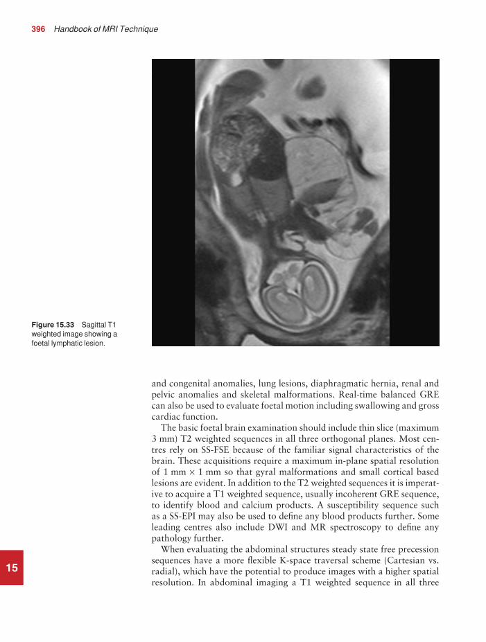
396 Handbook of MRI Technique
15
and congenital anomalies, lung lesions, diaphragmatic hernia, renal andpelvic anomalies and skeletal malformations. Real-time balanced GREcan also be used to evaluate foetal motion including swallowing and grosscardiac function.
The basic foetal brain examination should include thin slice (maximum3 mm) T2 weighted sequences in all three orthogonal planes. Most cen-tres rely on SS-FSE because of the familiar signal characteristics of thebrain. These acquisitions require a maximum in-plane spatial resolutionof 1 mm × 1 mm so that gyral malformations and small cortical basedlesions are evident. In addition to the T2 weighted sequences it is imperat-ive to acquire a T1 weighted sequence, usually incoherent GRE sequence,to identify blood and calcium products. A susceptibility sequence such as a SS-EPI may also be used to define any blood products further. Someleading centres also include DWI and MR spectroscopy to define anypathology further.
When evaluating the abdominal structures steady state free precessionsequences have a more flexible K-space traversal scheme (Cartesian vs.radial), which have the potential to produce images with a higher spatialresolution. In abdominal imaging a T1 weighted sequence in all three
Figure 15.33 Sagittal T1weighted image showing afoetal lymphatic lesion.
9781405160858_4_015.qxd 29/05/2008 10:39 Page 396

Paediatric imaging 397
orthogonal planes is mandatory to identify the meconium within thebowel. Foetal imaging can be a challenge but with the appropriate prep-aration of the mother it is a worthwhile experience. Foetal MRI is, bydefinition, potentially a very stressful time for the mother so it is essentialthat centres performing foetal MRI spend the time counselling the motherregarding the scan, prepare her for the MR examination to reduce heranxiety and assist her to lie on the examination table in a comfortableenvironment.
Conclusions
Children and claustrophobic adults can present special challenges to theMR unit. Safety is the most important consideration. Whatever policy thecentre adopts for scanning these patients, no expense should be spared toensure their safety whilst they are unconscious in the unit. If it is decidedthat monitoring equipment or anaesthetist time is too expensive, thenarrangements should be made to have these patients scanned at otherfacilities. In addition, it is important not to overlook the parents. It is easy to forget that parents are very anxious about the condition of theirchild and the outcome of the examination. Try to keep them continuallyinformed and involve them as much as possible. All these measures shouldprovide a safe, relaxed environment for paediatric examinations. Finally,the advent of motion sensitive correction, parallel imaging and ultrafastsequences may negate the need for sedation or general anaesthesia as thescan times are so short that even the most restless patient can be examinedsuccessfully.
15
9781405160858_4_015.qxd 28/05/2008 17:13 Page 397

Note: page numbers in italics refer to figures, those in bold refer to tables
emergencies 362equipment 354–5facilities 354monitoring 355–6paediatric imaging 353–63patient preparation 356–8recovery 54, 362staffing 353–4strategies 358, 360–2
aneurysm clips, intra-cranial 50angiography see magnetic resonance angiography (MRA)ankle
anatomy 329impingement syndromes 335prostheses/screws 335
ankle imaging 329–35additional sequences 334artefacts 335contrast usage 335equipment 329image optimization 334–5indications 329paediatric 384patient considerations 335patient positioning 330protocol 330, 331, 332, 333technical issues 334–5
anxiolysis 358aorta
paediatric imaging 393phase artefacts 162–3
aortic aneurysm 394aortic arch imaging 191
paediatric 393apparent diffusion coefficient (ADC) 72–3arachnoiditis, lumbar spine imaging 160artefacts 7, 35, 38–40
abdomen vascular imaging 241aliasing 38–9ankle imaging 335axilla imaging 211biliary system imaging 224–5, 231–2
Index
398
Aabdomen imaging 217–42
adrenal glands 226–32biliary system 219–25kidneys 226–32liver 219–25magnetic resonance angiography 240–2paediatric 365pancreas 233–8parameters 217–18vascular 239–42
artefacts 241contrast usage 241–2equipment 239image optimization 240–2indications 239patient consideration 241patient positioning 239–40protocol 240, 241technical issues 240
vascular anatomy 239abscesses
Brodie’s 384contrast use 80rectal 391
acoustic neuroma 94adrenal gland imaging 226–32
additional sequences 228, 231equipment 226indications 226patient positioning 227protocol 227–8
adrenal glands, anatomy 226aliasing 3, 38–9
frequency wrap 39lumbar spine imaging 163, 164phase wrap 39
alignment lights 4, 6anaesthesia
advantages over sedation 360departmental policies 362–3disadvantages over sedation 361
9781405160858_6_ind.qxd 28/05/2008 17:15 Page 398

Index 399
black blood 180, 189brachial plexus imaging 215–16brain imaging 79–80breast imaging 206, 208bright blood 180, 189chemical misregistration 39chemical shift 39cine imaging 46elbow imaging 284femur imaging 312–13flow-related 37foot imaging 341forearm imaging 288hand imaging 298head and neck vascular imaging 137heart and great vessels imaging 192–3hip imaging 308humerus imaging 276internal auditory meati imaging 95kidney imaging 231–2knee imaging 323larynx imaging 120liver imaging 224–5lower limb vascular imaging 348lung imaging 178–80magnetic susceptibility 40, 116mediastinum imaging 178–80motion 80obstetrics 258orbit imaging 105paediatric imaging 387, 391pancreas imaging 238paranasal sinus imaging 110parathyroid gland imaging 124pelvis imaging
female 256male 252
pharynx imaging 115–16phase mismapping 38pituitary fossa imaging 100posterior fossa imaging 95remedies 35respiratory 387, 391salivary gland imaging 127shoulder imaging 271–2spine imaging
cervical 147–8lumbar 162–3, 164, 165thoracic 154–5whole spine 169
swallowing 115–16temporal lobe imaging 87temporomandibular joint imaging 132thymus imaging 196–7thyroid gland imaging 124tibia and fibula imaging 328truncation 40, 148wrist imaging 298
arteriovenous malformations 376, 377arthrography 56, 270
ankle imaging 335elbow imaging 284hand imaging 298hip imaging 306, 307, 309knee imaging 324shoulder imaging 269, 272wrist imaging 298
astrocytoma 374, 380avascular necrosis 383
hip 305axial perfusion imaging, brain 73, 77, 78axilla imaging 210–12
additional sequences 211artefacts 211contrast usage 212equipment 210image optimization 211–12indications 210patient considerations 211–12patient positioning 210protocol 210technical issues 211
Bbiliary system anatomy 219biliary system imaging 219–25
additional sequences 222, 223, 224artefacts 224–5, 231–2contrast usage 225, 232equipment 219image optimization 224–5, 231–2indications 219patient considerations 225, 232patient positioning 219–20protocol 220, 221, 222technical issues 224, 231
black blood imaging 180, 188, 189abdomen 240paediatric 393, 394, 395
blindness, orbit imaging 105–6blood, T2/T1 ratio 26blood pool agents 56–7body imaging
paediatric 387–95see also abdomen imaging; chest imaging
BOLD (blood oxygenation level dependent) 29bony tumours, contrast usage 148, 155bowel imaging 392bowel motion
female pelvis imaging 256kidney imaging 232male pelvis imaging 252
brachial plexus anatomy 213brachial plexus imaging 213–16
artefacts 215–16contrast usage 216equipment 213image optimization 214–16indications 213patient considerations 216
9781405160858_6_ind.qxd 28/05/2008 17:15 Page 399

400 Index
patient positioning 213–14protocol 214technical issues 214–15
brain imaging 63–81additional sequences 65, 67, 68, 69, 70–3, 74, 75–7anatomy 63artefacts 79–80equipment 64foetal 396image optimization 77–9indications for imaging 64infarct age 80–1paediatric 65, 67, 366–77
indications 364tumours 373–5
patient considerations 80patient positioning 64, 134protocol 64–5, 66–7technical issues 77–81vascular 134, 135
breastanatomy 198angiogenesis 199hypervascularity 199neovascularity 199overcompression 200
breast imaging 198–209additional sequences 205artefacts 206, 208bilateral 209compression 199–200contrast usage 199, 208–9equipment 199European method 202, 203, 204, 205–6image optimization 205–6, 207, 208–9indications 198–9patient considerations 208patient positioning 199–200protocol 200–2, 203, 204shimming 206, 207technical issues 205–6, 207unilateral 209US method 200–2, 206
breast implants 199contrast usage/protocol 204–5
breath-holding systems, paediatric imaging 387, 394breathing navigator 387, 391, 395breathing systems 360bright blood imaging 188, 189, 191, 192
abdomen imaging 240paediatric 393, 394, 395
Brodie’s abscess 384
Ccable safety 44, 50–1carbon dioxide partial pressure (PCO2) 363cardiac cine 189–90
paediatric 392, 394cardiac gating 41–4cardiac imaging see heart and great vessel imaging
cardiac perfusion studies 191carotid vessel disease 377carotid vessel pulsation, temporomandibular joint imaging 132cerebrospinal fluid, T2/T1 ratio 26cervical node imaging 126cervical spine, anatomy 140, 141cervical spine imaging 140–9
additional sequences 142, 145–6artefacts 147–8contrast usage 148–9equipment 141image optimization 146–9indications 140patient considerations 148patient positioning 141protocol 142, 143–4swallowing 148technical issues 146–7
chemical misregistration 39chemical shift 39
femur imaging 312–13kidney imaging 231–2tibia and fibula imaging 328
chemical/spectral presaturationankle imaging 332, 333biliary system imaging 222breast imaging 200–1, 202, 204, 206coherent 332, 333contrast usage 149, 155elbow imaging 279, 280, 282–3femur imaging 312foot imaging 338, 339, 340forearm imaging 287, 288growth plate evaluation 386hand imaging 292, 293, 295, 296hip imaging 302, 303, 304, 305, 308humerus imaging 275knee imaging 316, 318, 320, 321, 323liver imaging 222, 225male pelvis imaging 247musculoskeletal imaging 383obstetrics 258paediatric imaging 390, 391
kidney 389liver 388pituitary 374, 386spine 379, 380
shoulder imaging 264, 267, 268thymus imaging 197tibia and fibula imaging 327, 328wrist imaging 292, 293, 295, 296
chest imaging 171–216axilla 210–12brachial plexus 213–16breast 198–209heart and great vessels imaging 182–94lung imaging 173–81mediastinum imaging 173–81parameters 171–2thymus 194–7
9781405160858_6_ind.qxd 28/05/2008 17:15 Page 400

Index 401
chiasm 102, 104cine imaging
gating 46see also cardiac cine
circle of Willis 133TOF-MRA 137
claustrophobia 52–3brain imaging 80female pelvis imaging 257internal auditory meati imaging 95male pelvis imaging 247paranasal sinus imaging 110pituitary fossa imaging 100posterior fossa imaging 95temporal lobe imaging 88
coarctation of the aorta 392, 394coils
paediatric imaging 364rectal 246, 250, 252safety 51types 2–3using 3–4
communication, intercom system 53congenital heart disease 392, 393, 394, 395congenitally dislocated hips (CDH) 386–7contrast agents 55–7
abdomen vascular imaging 241–2ankle imaging 335axilla imaging 212biliary system imaging 225, 232bowel imaging 392brachial plexus imaging 216brain imaging 80–1breast imaging 199, 208–9breast implants 204–5chelates 55–6elbow imaging 284femur imaging 313forearm imaging 288hand imaging 298head and neck vascular imaging 135, 137heart and great vessels imaging 191, 192, 194hip imaging 306, 307, 309humerus imaging 276internal auditory meati imaging 95kidney imaging 232knee imaging 324larynx imaging 120liver imaging 225lower limb vascular imaging 349lung imaging 181mediastinum imaging 181negative 56orbit imaging 106pancreas imaging 238paranasal sinus imaging 110parathyroid gland imaging 124pelvis imaging
female 257male 247, 249
pharynx imaging 116pituitary fossa imaging 100positive 55–6posterior fossa imaging 95salivary gland imaging 128shoulder imaging 272spine imaging
cervical 148–9lumbar 165thoracic 155whole spine 170
temporal lobe imaging 88temporomandibular joint imaging 132thymus imaging 197thyroid gland imaging 124tibia and fibula imaging 328wrist imaging 298
contrast to noise ratio (CNR) 17hand imaging 297hip imaging 306–7, 308wrist imaging 297
contrast usage 7coordinates 6cord compression 169coronary artery imaging 191Crohn’s disease 391cruciate ligament 315Cushing’s disease, contrast usage 100
Ddecision strategies 20diaphragm movement, thoracic spine imaging 155diastematomyelia 378diethylene triaminepentaacetic acid (DTPA) 55–6diffusion tensor imaging
brain 73, 74–6paediatric 370
breast 205heart and great vessels 191
diffusion weighted imaging (DWI) 29–30biliary system 224, 231brain 71–3, 370liver 224, 231paediatric 370, 387, 391pancreas 236pelvis
female 256male 249, 251
disc prolapse, lumbar 165Dixon technique, contrast usage 149, 155Dobutamine™ 191dynamic imaging 28–9
knee 322temporomandibular joint 131
Eecho planar imaging (EPI) 28–30
brain 70, 73, 77, 78foetal 396paediatric 370, 371
9781405160858_6_ind.qxd 28/05/2008 17:15 Page 401

402 Index
gradient echo 73, 77, 78, 205biliary system 224brain 73, 77, 78female pelvis 256liver 224male pelvis 249, 251
heart and great vessel 190paediatric 390pharynx 115safety 51spin echo 205
biliary system 224brain paediatric 370, 371female pelvis 256foetal brain 396liver 224paediatric 390
see also single shot echo planar imaging (SS-EPI)echo time (TE) 15, 21
brain imaging 78–9gating 46inversion recovery 25steady state free precession 27
echo train length (ETL) 23, 24brain imaging 78–9
temporal lobe epilepsy 372inversion recovery 25
elbow, anatomy 277, 278elbow imaging 277–84
additional sequences 279, 282artefacts 284contrast usage 284equipment 277image optimization 282, 284indications 277patient considerations 284patient positioning 278protocol 278–9, 280–2, 283shimming 284technical issues 282, 284
electrocardiogram (ECG) gating 178–9, 193, 194lead placement 41–3thymus imaging 196, 197trace improvement 43–4
entry slice phenomenon 36ependymomas, contrast usage 148, 155epilepsy, paediatric brain imaging 372–3equipment 2–4
conditional aspects 356sedation 359–60
Ewing’s sarcoma 385, 386
Ffailed back syndrome 165Fallot’s tetralogy 394fast spin echo (FSE) 3, 15, 16, 23–4
abdomen imaging 217adrenal gland imaging 227–8ankle imaging 330, 332axilla imaging 210, 211
biliary system imaging 220, 221, 222, 223, 231brachial plexus imaging 214, 215brain imaging 61, 64–5, 66, 77–8
paediatric 366, 367breast imaging 200, 202, 203, 205breast implants 204chest imaging 171elbow imaging 278–9, 280, 281, 282epilepsy investigations 373femur imaging 311–12foot imaging 337–8, 339, 340, 341forearm imaging 286–7, 288hand imaging 290, 292, 293–5, 295, 296, 297heart and great vessels imaging 183, 184hip imaging 302–3, 304, 305, 306, 308humerus imaging 274–5, 276hydrocephalus 375internal auditory meati imaging 92–3, 94inversion recovery 25, 390
breast implants 204–5temporal lobe imaging 85, 86
kidney imaging 227–8, 231knee imaging 316, 318, 319–20, 321larynx imaging 117–18, 119liver imaging 220, 221, 222, 223
paediatric 388lower limb imaging 299lung imaging 175, 176, 177mediastinum imaging 175, 176, 177motion artefacts 80musculoskeletal imaging 383obstetrics 258orbit imaging 102, 104paediatric imaging 350, 384, 388–9pancreas imaging 234, 235paranasal sinus imaging 108–9parathyroid gland imaging 123–4pelvis imaging 243
female 254, 255, 256male 246–7, 248, 249, 251, 252
pharynx imaging 112–13, 114, 115pituitary fossa imaging 97–8, 99posterior fossa imaging 92–3, 94, 95salivary gland imaging 126, 127shoulder imaging 264, 265, 266, 268, 271spine imaging 138
cervical 142, 143–4, 147–8lumbar 156–7, 159, 160, 161–2, 162, 165paediatric 378, 380, 381, 382–3thoracic 150–1, 152–3, 154whole spine 166–7, 169
temporal lobe imaging 83, 84, 87temporomandibular joint imaging 130, 131thyroid gland imaging 122, 123–4tibia and fibula imaging 326, 327, 328upper limb imaging 261wrist imaging 290, 292, 293–5, 295, 296, 297see also inversion recovery fast spin echo (IR-FSE); single
shot fast spin echo (SS-FSE)fat saturation (FAT SAT) 8
9781405160858_6_ind.qxd 28/05/2008 17:15 Page 402

Index 403
fat suppression techniques 8axilla imaging 212breast imaging 206kidney imaging 232knee imaging 323tibia and fibula imaging 328see also chemical/spectral presaturation
femur anatomy 310femur imaging 310–13
artefacts 312–13contrast usage 313equipment 310–11image optimization 312–13indications 310patient considerations 313patient positioning 311protocol 311–12technical issues 312
fibula see tibia and fibula imagingfield of view (FOV) 2, 16, 21
abdomen imaging 218vascular 240
ankle imaging 335asymmetric 8, 18–19axilla imaging 211biliary system imaging 231brachial plexus imaging 215brain imaging 62, 79breast imaging 206, 208chest imaging 172elbow imaging 282, 284femur imaging 311, 312, 313foot imaging 341forearm imaging 287–8hand imaging 298heart and great vessels imaging 193hip imaging 302, 307, 308humerus imaging 276kidney imaging 231knee imaging 323larynx imaging 119, 120lower limb imaging 300
vascular 348lung imaging 178, 179–80mediastinum imaging 178, 179–80musculoskeletal imaging 383neck vascular imaging 136obstetrics 258orbit imaging 105paediatric imaging 351, 364, 394pancreas imaging 238paranasal sinus imaging 110parathyroid gland imaging 123–4pelvis imaging 244
female 256male 251, 252
pharynx imaging 115pituitary fossa imaging 99, 100rectangular 8, 18–19salivary gland imaging 127
shoulder imaging 271spatial resolution 17–18spine imaging 139
cervical 147lumbar 162, 163, 164whole spine 168–9
temporal lobe imaging 87temporomandibular joint imaging 131, 132thoracic spine imaging 154, 155thymus imaging 196thyroid gland imaging 123, 124tibia and fibula imaging 326, 327upper limb imaging 262wrist imaging 298
FLAIR sequences 16, 17abdomen imaging 217brain imaging 61, 68
paediatric 366, 368paediatric tumours 375
chest imaging 171hydrocephalus 375long T1 25lower limb imaging 299paediatric imaging 350, 366, 368, 375pelvis imaging 243spine imaging 138temporal lobe epilepsy 372temporal lobe imaging 87upper limb imaging 261
flip angle 15flow artefact remedies 37flow compensation (FC) 8flow phenomena 35–40fluid alternated inversion recovery see FLAIR sequencesfoetal MR 395–6foot anatomy 336foot imaging 336–42
additional sequences 340, 341artefacts 341equipment 336image optimization 341–2indications 336patient considerations 342patient positioning 337protocol 337–8, 339, 340scan plane alignment 337technical issues 341
forearm anatomy 285forearm imaging 285–8
artefacts 288contrast usage 288equipment 285image optimization 287–8indications 285patient considerations 288patient positioning 285–6protocol 286–7technical issues 287–8
fractional anisotropy map, brain imaging 73, 74, 75functional MRI (fMRI) 29
9781405160858_6_ind.qxd 28/05/2008 17:15 Page 403

404 Index
Ggadolinium 55–6
administration route 56chelates 55–6knee imaging 324liver imaging 225temporomandibular joint imaging 132
gating 41–6cable safety 45, 50–1ECG 41–4, 178–9, 193, 194
thymus imaging 196, 197lead placement 41–3parameters 46peripheral 45–6
biliary system imaging 224liver imaging 224pituitary fossa imaging 100thoracic spine imaging 154whole spine imaging 169
during sedation/anaesthesia 356trace improvement 43–4
general anaesthesiabrain imaging 80see also anaesthesia
Gibbs artefact 40cervical spine imaging 148
gradient echo (GRE)balanced 16, 26, 46
abdomen imaging 217brain imaging 61cardiac imaging 393cervical spine imaging 145–6chest imaging 171foetal imaging 395, 396lower limb imaging 299paediatric imaging 350, 393, 394pelvis imaging 243spine imaging 138upper limb imaging 261
brain imaging 81paediatric 370, 371, 375tumours 375vascular 134
chemical misregistration 39coherent 16, 25–6, 46
abdomen imaging 217ankle imaging 332, 334, 335brain imaging 61cervical spine imaging 144, 145chest imaging 171elbow imaging 279, 282, 283foot imaging 338, 340hand imaging 292, 293, 295, 297heart and great vessels imaging 189–90hip imaging 303, 304, 305knee imaging 315–16, 317, 321, 323lower limb imaging 299lumbar spine imaging 157, 158, 159paediatric imaging 350, 384pelvis imaging 243
shoulder imaging 264, 265, 271spine imaging 138upper limb imaging 261whole spine imaging 166, 167wrist imaging 292, 293, 295, 297
congenitally dislocated hips 387contrast-enhanced 3D 377gadolinium-enhanced of heart 191hand imaging 298heart and great vessels imaging 190, 191, 193incoherent 16, 27
abdomen imaging 217adrenal gland imaging 227–8, 229–30ankle imaging 330, 334axilla imaging 210biliary system imaging 220, 222, 223brachial plexus imaging 214, 215brain imaging 61, 68, 69, 70brain paediatric imaging 369–70breast imaging 200–2, 204cervical spine imaging 145chest imaging 171elbow imaging 278–9epilepsy investigations 373female pelvis imaging 254femur imaging 311foetal brain 396foot imaging 337forearm imaging 286–7hand imaging 290, 291, 295, 297heart and great vessels imaging 183, 184, 189–90,
191hip imaging 302, 305, 306, 307internal auditory meati imaging 94–5kidney imaging 227–8, 229–30knee imaging 318, 320liver imaging 220, 222, 223lower limb imaging 299lower limb vascular imaging 345lung imaging 174–5, 176, 177male pelvis imaging 246–7, 249, 250mediastinum imaging 174–5, 176, 177paediatric imaging 350, 369–70, 391pancreas imaging 227, 233–4, 236pelvis imaging 243pituitary fossa imaging 98, 99, 100posterior fossa imaging 94–5shoulder imaging 264spine imaging 138temporal lobe imaging 84, 85, 87thymus imaging 195tibia and fibula imaging 326upper limb imaging 261wrist imaging 290, 291, 295, 297
inflammatory bowel disease 392in-phase fast 391internal auditory meati imaging 92–3, 94, 95lung imaging 178magnetic resonance angiography 30mediastinal imaging 178
9781405160858_6_ind.qxd 28/05/2008 17:15 Page 404

Index 405
musculoskeletal imaging 383neck vascular imaging 136paediatric 390
3D 386pharynx imaging 115posterior fossa imaging 92–3, 95SPAMM tagging 190spine imaging
cervical 144, 145–6, 148lumbar 157, 158, 159thoracic 154
temporomandibular joint imaging 131wrist imaging 298
gradient echo echo planar imaging (GRE-EPI) 205biliary system imaging 224brain imaging 73, 77, 78liver imaging 224pelvis imaging
female 256male 249, 251
gradient moment nulling (GMN) 8abdominal vascular imaging 240ankle imaging 335axilla imaging 211biliary system imaging 224, 231brachial plexus imaging 215brain imaging 80
vascular 134, 137bright blood evaluation 188, 189elbow imaging 284femur imaging 313flow artefact remedies 37forearm imaging 288gating 46hand imaging 298heart and great vessels imaging 193hip imaging 308humerus imaging 276intra-voxel dephasing 36kidney imaging 231knee imaging 323larynx imaging 120liver imaging 224lung imaging 180magnetic resonance angiography 30mediastinum imaging 180neck vascular imaging 136orbit imaging 105pancreas imaging 238paranasal sinus imaging 110parathyroid gland imaging 124pelvis imaging
female 256male 252
phase artefacts 162shoulder imaging 271spine imaging
cervical 147, 148thoracic 154whole spine 169
temporal lobe imaging 87temporomandibular joint imaging 132thyroid gland imaging 124tibia and fibula imaging 328wrist imaging 298
gradient moment rephasing (GMR) 8growth plate evaluation 386
Hhand anatomy 289hand imaging 289–98
additional sequences 295, 296–7artefacts 298contrast usage 298equipment 289image optimization 297–8indications 289patient considerations 298patient positioning 290protocol 290, 291, 292, 293–5technical issues 297
HASTE see single shot fast spin echo (SS-FSE)head and neck imaging 61–137
brain 63–81internal auditory meati 89–95larynx imaging 117–20orbit imaging 101–6parameters 61–2paranasal sinus imaging 107–10parathyroid gland imaging 121–4pharynx imaging 111–16pituitary fossa imaging 96–100posterior fossa 89–95salivary gland imaging 125–8temporal lobes 82–8temporomandibular joint imaging 129–32thyroid gland imaging 121–4vascular 133–7
artefacts 137contrast usage 135, 137equipment 133image optimization 136–7indications 133patient considerations 137patient positioning 134protocol 134, 135, 136technical issues 136–7
vascular anatomy 133heart and great vessels anatomy 182heart and great vessels imaging 182–94
additional sequences 190–1, 192artefacts 192–3contrast usage 191, 192, 194equipment 182image optimization 192–4indications 182paediatric 365, 391, 392, 393–5patient considerations 194patient positioning 183protocol 183, 184–6, 187–90
9781405160858_6_ind.qxd 28/05/2008 17:15 Page 405

406 Index
specific cardiac views 183, 185–6, 187, 188technical issues 192
helium, hyperpolarized 56lung imaging 181
hepatoblastoma 388hip(s)
anatomy 301avascular necrosis 305congenital dislocation 386–7prosthesis/pins 308, 313
hip imaging 301–9additional sequences 305–6artefacts 308bilateral 302–3, 304, 305, 307contrast usage 306, 307, 309equipment 301–2image optimization 306–9indications 301patient considerations 308–9patient positioning 302protocol 302–3, 304, 305spatial resolution 306–7technical issues 306–9unilateral 302, 305, 307
hippocampus, paediatric imaging 372horizontal alignment light 4humerus anatomy 273humerus imaging 273–6
artefacts 276contrast usage 276equipment 273image optimization 275–6indications 273paediatric 384patient considerations 276patient positioning 274protocol 274–5technical issues 275–6
hydrocephalus 375hyperpolarized helium 56
lung imaging 181hypoplastic left heart 394hypothalamus, paediatric seizures 373
Iimage optimization 7inferior vena cava, phase artefacts 162–3inflammatory bowel disease 392infusion pumps 360intermedullary cyst 378internal auditory meati imaging 89–95
additional sequences 91, 92anatomy 89artefacts 95contrast 95equipment 89high-resolution technique 91–3, 94image optimization 93–5indications 89patient considerations 95
patient positioning 89protocol 90, 91
intra-voxel dephasing 36inversion recovery (IR) 16, 24–5
abdomen imaging 217black blood imaging 188, 189brain imaging 61, 65, 67breast implants 204–5chest imaging 171double 188lower limb imaging 299paediatric imaging 350, 390pelvis imaging 243spine imaging 138triple 188upper limb imaging 261
inversion recovery fast spin echo (IR-FSE) 25breast implants 204–5temporal lobe imaging 85, 86
iron oxides 56
KK space 23, 24kidney anatomy 226kidney imaging 226–32
additional sequences 228, 231artefacts 231–2contrast usage 232equipment 226image optimization 231–2indications 226paediatric 389patient considerations 232patient positioning 227protocol 227–8technical issues 231
kneeanatomy 314prostheses 323
knee imaging 314–24additional sequences 321–2artefacts 323contrast usage 324dynamic 322equipment 315image optimization 322–4indications 315patient considerations 323–4patient positioning 315protocol 315–16, 317, 318, 319–20, 321technical issues 322–3
Llarynx anatomy 111larynx imaging 117–20
artefacts 120contrast usage 120equipment 117image optimization 119–20indications 117
9781405160858_6_ind.qxd 28/05/2008 17:15 Page 406

Index 407
patient considerations 120patient positioning 117protocol 117–18, 119swallowing 120technical issues 119
lipoma, intraspinal 379liver anatomy 219liver imaging 219–25, 224
additional sequences 222, 223, 224artefacts 224–5contrast agents 56, 225equipment 219image optimization 224–5indications 219metastases 225paediatric tumours 388patient considerations 225patient positioning 219–20protocol 220, 221, 222technical issues 224
local coils 3longitudinal alignment light 4lower limb imaging 299–349
ankle 329–35femur 310–13foot 336–42hips 301–9knee 314–24parameters 299–300tibia and fibula 325–8vascular anatomy 343, 344vascular imaging 343–9
artefacts 348contrast usage 349equipment 344image optimization 346, 348indications 343–4patient considerations 348–9patient positioning 345protocol 345–6, 347
lumbar spine imaging 156–65aliasing 163, 164artefacts 162–3, 164, 165contrast usage 165equipment 156image optimization 160, 162–3, 164, 165indications 156patient considerations 165patient positioning 156phase axis swapping 163, 164protocol 156–7, 158–9technical issues 160, 162
lung imaging 173–81additional sequences 175, 177artefacts 178–80contrast usage 181equipment 173image optimization 177–81indications 173patient considerations 180–1
patient positioning 174perfusion studies 175protocol 174–5, 176–7technical issues 177–8ventilation studies 177
lungs, anatomy 173
Mmagic angle, shoulder imaging 271–2magnet–haemodynamic effect 194magnetic field homogeneity, breast imaging 206magnetic resonance angiography (MRA) 30–3
abdomen imaging 240–2contrast enhanced 31–2
abdomen imaging 240great vessels 191magnetization transfer contrast 32–3paediatric 375, 376, 377
brain tumours 375indications 365
phase contrast 31abdomen imaging 218brain imaging 62, 137brain vascular imaging 134, 135chest imaging 172hydrocephalus 375lower limb imaging 300, 348paediatric imaging 351, 377pelvis imaging 244spine imaging 139upper limb imaging 262
time of flight 30–1abdomen imaging 218, 240, 241brain imaging 62, 136–7brain vascular imaging 134chest imaging 172contrast agent use 349lower limb imaging 300, 345–6, 348, 349neck vascular imaging 134, 136paediatric imaging 351, 376, 377pelvis imaging 244spine imaging 139upper limb imaging 262
magnetic resonance arthrography 56, 270ankle imaging 335elbow imaging 284hand imaging 298hip imaging 306, 307, 309knee imaging 324shoulder imaging 269, 272wrist imaging 298
magnetic resonance cholangiopancreatography (MRCP) see single shot fast spin echo (SS-FSE)
magnetic resonance myelography 168magnetic resonance neurography 168magnetic resonance sialography 127magnetic resonance urography 228, 231
paediatric 391magnetic safety 49–50magnetic susceptibility 40
9781405160858_6_ind.qxd 28/05/2008 17:15 Page 407
408 Index
magnetization, transverse 26magnetization transfer (MT) contrast
brain imaging 70paediatric 369–70
head and neck vascular imaging 137MRA 32–3
magnetization transfer (MT) sequences 17manganese contrast agent 56Marfan’s syndrome 382matrix
abdomen imaging 218brain imaging 62chest imaging 172decrease 21increase 21lower limb imaging 300pelvis imaging 244spine imaging 139upper limb imaging 262
mediastinum anatomy 173mediastinum imaging 173–81
additional sequences 175, 177artefacts 178–80contrast usage 181equipment 173image optimization 177–81indications 173patient considerations 180–1patient positioning 174protocol 174–5, 176–7
medulloblastoma 379leptomeningeal spread 148, 155
menstrual cycle, breast imaging 208–9metastases
brain 374–5cervical spine 147contrast use 80liver 225paediatric imaging 382, 386
brain 374–5spinal 154, 165, 169, 170
paediatric 382STIR sequence 147, 154, 165, 169
micro-adenomas, contrast usage 100multi-coils 3multi-phase imaging, heart and great vessels imaging 189multiple sclerosis, contrast usage 80, 155musculoskeletal imaging
paediatric 365, 383–7see also lower limb imaging; spine imaging; upper limb
imagingmyelography 168
Nnasopharyngeal tumours 115neck
vascular imaging 134, 136see also head and neck imaging
neurofibromatosis 381, 382neurography 168
number of excitations/signal averages (NEX/NSA) 16, 17, 21abdomen imaging 218axilla imaging 211brain imaging 62, 79chest imaging 172foot imaging 341hand imaging 297heart and great vessels imaging 192hip imaging 307humerus imaging 276internal auditory meati imaging 94larynx imaging 119, 120lower limb imaging 300lung imaging 178mediastinal imaging 178obstetrics 258orbit imaging 105paediatric imaging 351, 387, 391
pituitary 374paranasal sinus imaging 110parathyroid gland imaging 123, 124pelvis imaging 244pharynx imaging 115pituitary fossa imaging 99pituitary imaging 374posterior fossa imaging 94salivary gland imaging 127spine imaging 139
cervical 147, 148thoracic 154
temporomandibular joint imaging 131thymus imaging 196thyroid gland imaging 123, 124upper limb imaging 262volume imaging 20wrist imaging 297
Oobstetrics 258–60
artefacts 258patient considerations 258–9
open magnet systems, paranasal sinus imaging 109optic chiasm, paediatric imaging 373–4optic nerve 102, 103–4
visualization 109oral tumours 115orbit imaging 101–6
artefacts 105contrast 106equipment 101fat suppression techniques 105, 106image optimization 102, 105–6indications 101patient considerations 105–6patient positioning 101–2protocol 102, 103–4technical issues 102, 105
orbitsanatomy 101fat content 105
9781405160858_6_ind.qxd 28/05/2008 17:15 Page 408

Index 409
oropharyngeal tumours 115osteochondritis 383
dissecans 385osteomyelitis
humerus 384spinal 170, 380
osteosarcoma 386oversampling 8oxygen administration 170, 181
Ppacemakers, MR contraindication 50paediatric imaging 350–97
anaesthesia (see below sedation/anaesthesia)artefacts 387, 391babies 361
sedation/anaesthesia 361body 387–95brain 65, 67, 364, 366–77cardiac 392, 393, 394–5coils 364environment 351–3epilepsy 372–3examination 363–4family members 353growth plate evaluation 386hydrocephalus 375indications 364–5magnetic resonance angiography 365, 375, 376, 377medical assessment 356–7musculoskeletal 365, 383–7optic chiasm 373–4parameters 350–1pituitary disease 373–4pre-examination fasting 357resuscitation 362scoliosis 382–3sedation/anaesthesia 353–63
babies 361children 361–2departmental policies 362–3emergencies 362equipment 354–5facilities 354gaseous agents 357IV agents 357monitoring 355–6neonates 361oral agents 357–8patient preparation 356–8recovery 362staff considerations 353–4strategies 358–62
spine 377–83thymus imaging 197tumours 385, 386verbal reinforcement 352–3
pancreas anatomy 233pancreas imaging 233–8
artefacts 238
contrast usage 238equipment 233image optimization 236, 238indications 233patient considerations 238patient positioning 233protocol 233–4, 235, 236technical issues 236, 238
parallel imaging 3paranasal sinus imaging 107–10
additional sequences 109artefacts 110contrast usage 110equipment 107image optimization 109–10indications 107patient considerations 110patient positioning 107protocol 108–9technical issues 109–10
paranasal sinuses, anatomy 107parathyroid gland imaging 121–4
artefacts 124contrast usage 124equipment 122image optimization 123–4indications 122patient considerations 124patient positioning 122protocol 122, 123swallowing 124technical issues 123–4
parathyroid glands, anatomy 121parotid gland imaging
patient positioning 125–6protocol 126
patella, tracking 318, 321patient(s)
considerations 7counselling 51–3immobilization 53–4information for 51–2intercom system 53
patient care 49–54after care 54
patient positioning 4, 5, 6, 53–4foam pads 53–4
patient safety 49–51screening 49–50
pelvis imaging 243–60female 253–7
additional sequences 256anatomy 253artefacts 256contrast usage 257equipment 253image optimization 256–7indications 253patient considerations 257patient positioning 253–4
9781405160858_6_ind.qxd 28/05/2008 17:15 Page 409

410 Index
protocol 254, 255technical issues 256
male 245–52additional sequences 249, 250, 251anatomy 245artefacts 252contrast usage 247, 249equipment 245image optimization 251–2indications 245patient considerations 247patient positioning 245–6protocol 246–7, 248, 249technical issues 251–2
obstetrics 258–60technical issues 258–9
paediatric 391parameters 243–4
perfusion studies 30brain imaging 81cardiac 191lung imaging 175
peristaltic movement, paediatric imaging 387pharynx anatomy 111pharynx imaging 111–16
additional sequences 113, 115artefact problems 115–16contrast usage 116equipment 111image optimization 115–16indications 111patient considerations 116patient positioning 111–12protocol 112–13, 114, 115technical issues 115
phase contrast MRA see magnetic resonance angiography(MRA), phase contrast
phase encoding directionbreast imaging 208lung imaging 179thymus imaging 196
phase mismapping 38phased array coils 2pinealoblastomas, contrast usage 148, 155pituitary disease, paediatric 373–4pituitary fossa imaging 96–100
additional sequences 98–9anatomy 96artefacts 100contrast 100equipment 96image optimization 99–100indications 96patient considerations 100patient positioning 96–7protocol 97–8technical issues 99
posterior fossa imaging 89–95additional sequences 91, 92anatomy 89
artefacts 95contrast 95equipment 89high-resolution technique 91–3, 94image optimization 93–5indications 89patient considerations 95patient positioning 89protocol 90, 91
protocols 4, 6–7proton density (PD) 24
acquisition for brain imaging 77–9ankle imaging 330, 331, 332, 333, 334, 335fast spin echo 23growth plate evaluation 386hand imaging 295, 296hydrocephalus 375incoherent gradient echo 27paediatric brain tumours 375spin echo 22wrist imaging 295, 296
pulmonary artery imaging 191pulse sequences 22–33
Rreal-time imaging 28
paranasal sinus imaging 109receive bandwidth 21rectal anomalies/abscesses 391rectal coils, male pelvis imaging 246, 250, 252relaxivity, blood pool agents 57renal imaging 392renal tumours, paediatric 389renal vascular anomaly, paediatric 389repetition time (TR) 15, 21
balanced gradient echo 26steady state free precession 27
respiratory bellows 391paediatric 47–8
respiratory compensation (RC) 8, 47–8biliary system imaging 224liver imaging 224lung imaging 178mediastinum imaging 178pancreas imaging 238phase reordered 24thoracic spine imaging 155
respiratory triggering 47–8paediatric 391, 394
rhabdomyosarcoma 386rhabdosarcoma 391
Ssafety
cable 45, 50–1coils 51patient 49–51
salivary gland imaging 125–8additional sequences 127artefacts 127
9781405160858_6_ind.qxd 28/05/2008 17:15 Page 410

Index 411
contrast usage 128equipment 125image optimization 127–8patient considerations 128patient positioning 125–6protocol 126swallowing 128technical issues 127
salivary glands, anatomy 125scan time 18–20
volume imaging 19–20scar tissue, lumbar 165scoliosis 382–3secretin 238sedation
advantages over anaesthesia 361brain imaging 80claustrophobia management 53contraindications 359–60deep 359departmental policies 362–3disadvantages over anaesthesia 360emergencies 362equipment 354–5facilities 354gaseous agents 357intravenous agents 357minimal 358moderate 359monitoring 355–6oral agents 357–8paediatric imaging 353–63patient preparation 356–8recovery 54, 362staffing 353–4strategies 358–62
seizures, complex partial 372shimming
ankle imaging 335breast imaging 206, 207elbow imaging 284female pelvis imaging 256foot imaging 341hand imaging 298knee imaging 323tibia and fibula imaging 328wrist imaging 298
short T1 inversion recovery see STIR sequencesshoulder anatomy 263shoulder imaging 263–72
additional sequences 268–9artefacts 271–2contrast usage 272equipment 263image optimization 269, 271indications 263magic angle 271–2patient considerations 272patient positioning 263–4protocol 264, 265–7, 268
spin dephasing 271–2technical issues 269, 271
sialography 127signal to noise ratio (SNR) 2, 3, 5, 15, 20
abdominal vascular imaging 240ankle imaging 334–5axilla imaging 211decision strategies 20elbow imaging 282foot imaging 341hand imaging 297heart and great vessels imaging 192hip imaging 306–7, 308internal auditory meati imaging 93–4knee imaging 322–3larynx imaging 119lung imaging 177–8mediastinal imaging 177–8musculoskeletal imaging 383orbit imaging 105paediatric imaging 364, 386, 387pancreas imaging 236, 238paranasal sinus imaging 110parathyroid gland imaging 123pelvis imaging
female 256male 251
pharynx imaging 115pituitary fossa imaging 99, 100salivary gland imaging 127shoulder imaging 271spatial resolution 17–18spine imaging
cervical 146–7, 148lumbar 160, 162thoracic 153–4whole spine 168–9
T1 weighted images 55temporal lobe imaging 87temporomandibular joint imaging 131thymus imaging 196thyroid gland imaging 123tibia and fibula imaging 327–8volume imaging 19–20wrist imaging 297
silicone breast implants, protocol 204–5silicone imaging 205silicone suppression 205single shot echo planar imaging (SS-EPI) 28
brain imaging 70breast imaging 205male pelvis imaging 249, 251motion artefacts 80
single shot fast spin echo (SS-FSE) 23–4biliary system imaging 222, 223, 224brain imaging 68, 69, 81breast imaging 205foetal MR 395, 396liver imaging 222, 223, 224lung imaging 175, 177
9781405160858_6_ind.qxd 28/05/2008 17:15 Page 411

412 Index
mediastinum imaging 175, 177motion artefacts 80obstetrics 258pancreas imaging 234, 235, 236, 237pelvis imaging
female 256male 249, 251
slice numbersabdomen imaging 218brain imaging 62chest imaging 172lower limb imaging 300paediatric imaging 350pelvis imaging 244spine imaging 139upper limb imaging 262
slice prescription 6slice thickness 21
abdomen imaging 218brain imaging 62chest imaging 172lower limb imaging 300paediatric imaging 350pelvis imaging 244spine imaging 139upper limb imaging 262
soft tissue lesions 386SPAMM (spatial modulation of magnetization) tagging 190spatial presaturation pulses
brachial plexus imaging 215–16breast imaging 208female pelvis imaging 256femur imaging 313flow artefact remedies 37foot imaging 341heart and great vessels imaging 193hip imaging 308lung imaging 179–80mediastinum imaging 179–80obstetrics 258spine imaging
cervical 147, 148lumbar 163, 164thoracic 155whole spine 169
thymus imaging 196–7spatial resolution 17–18
knee imaging 322thoracic spine imaging 154
specific absorption rate (SAR) 363spectrally selective inversion recovery (SPIR) 8spin dephasing, shoulder imaging 271–2spin echo (SE) 15, 16, 22, 23
abdomen imaging 217adrenal gland imaging 227–8ankle imaging 330axilla imaging 210, 211biliary system imaging 227–8, 231brachial plexus imaging 214, 215brain imaging 61, 64–5, 66–7, 70
breast imaging 200, 202, 203, 205chest imaging 171coherent 332coronal protocol 6–7diffusion weighted imaging 29–30elbow imaging 278–9, 280, 281femur imaging 311–12foot imaging 337–8, 340forearm imaging 286–7hand imaging 290, 292, 295heart and great vessels imaging 183, 184, 187–8, 190hip imaging 302, 305, 306, 308humerus imaging 274–5, 276internal auditory meati imaging 90–1, 92kidney imaging 227–8, 231knee imaging 318, 320, 321larynx imaging 117–18liver imaging 220, 221, 222, 223lower limb imaging 299lung imaging 174–5mediastinum imaging 174–5musculoskeletal imaging 383obstetrics 258orbit imaging 102, 103, 104paediatric imaging 350
pituitary disease 374pancreas imaging 233–4paranasal sinus imaging 108–9pelvis imaging 243
female 254, 256male 246–7, 249, 250
pharynx imaging 112–13pituitary fossa imaging 97–8, 99pituitary imaging 374salivary gland imaging 126shoulder imaging 264, 268, 271SPAMM tagging 190spine imaging 138
cervical 142, 143, 147lumbar 156–7, 159paediatric 382–3thoracic 150–1, 153, 154whole 166–7
temporal lobe imaging 83, 84temporomandibular joint imaging 130, 131thymus imaging 195thyroid gland imaging 122tibia and fibula imaging 326, 327upper limb imaging 261wrist imaging 290, 292, 295see also fast spin echo (FSE)
spin echo echo planar imaging (SE-EPI) 205biliary system imaging 224brain paediatric imaging 370, 371female pelvis imaging 256foetal brain 396liver imaging 224paediatric 391
spin tagged perfusion techniques, lung imaging 175spinal cord lesions, contrast usage 148
9781405160858_6_ind.qxd 28/05/2008 17:15 Page 412

Index 413
spine imaging 138–70additional sequences 167–8artefacts 169cervical spine 140–9contrast usage 170equipment 166image optimization 168–70indications 166lumbar spine 156–65paediatric 377–83, 385
indications 365parameters 138–9patient considerations 169–70patient positioning 166protocol 166–7technical issues 168–9thoracic spine 150–5tumours 379, 380, 381, 385, 386whole spine 166–70
steady state free precession (SSFP) 27abdomen imaging 217brain imaging 61chest imaging 171foetal imaging 396lower limb imaging 299paediatric imaging 350pelvis imaging 243spine imaging 138upper limb imaging 261
STIR sequences 16, 17abdomen imaging 217axilla imaging 210brain imaging 61breast imaging 205chest imaging 171excitation pulse 25femur imaging 311forearm imaging 287, 288hip imaging 308humerus imaging 275knee imaging 316, 318lower limb imaging 299orbit imaging 105, 106paediatric imaging 350, 386, 387, 390pelvis imaging 243shoulder imaging 271spine imaging 138
cervical 142, 147lumbar 160, 161–2, 165thoracic 154whole spine 167, 169
tibia and fibula imaging 326upper limb imaging 261
submandibular gland imaging 126superparamagnetic agents 56surface coils 3, 5susceptibility weighted imaging, paediatric brain 370,
371swallowing
artefacts 115–16
cervical spine imaging 148larynx imaging 120parathyroid gland imaging 124pharynx imaging 115–16salivary gland imaging 128thyroid gland imaging 124
TT1 enhancement agents 55T1 relaxation time, gadolinium contrast 55T1 weighting
fast spin echo 24incoherent gradient echo 27spin echo 22
T2 enhancement agents 56T2 relaxation time, gadolinium contrast 55T2 shine-through effects 72T2 weighting
acquisition for brain imaging 77–9coherent gradient echo 26fast spin echo 23, 24spin echo 22steady state free precession 27
technical issues 7temporal lobe anatomy 82temporal lobe epilepsy 372temporal lobe imaging 82–8
artefacts 87claustrophobia 88contrast agents 88equipment 82image optimization 85, 87–8indications 82patient considerations 88patient positioning 82–3protocol 83–5, 86technical issues 85, 87
temporomandibular joint anatomy 129temporomandibular joint imaging 129–32
additional sequences 131artefacts 132contrast usage 132equipment 129image optimization 131–2indications 129patient considerations 132patient positioning 129–30protocol 130–1technical issues 131
teratoma 381terminology 8tethered cord 378thoracic spine imaging 150–5
artefacts 154–5contrast usage 155equipment 150image optimization 153–5indications 150patient considerations 155patient positioning 150
9781405160858_6_ind.qxd 28/05/2008 17:15 Page 413

414 Index
protocol 150–1, 152–3technical issues 153–4
thymus imaging 194–7artefacts 196–7contrast usage 197equipment 195image optimization 196–7indications 195patient considerations 197patient positioning 195protocol 195technical issues 196
thyroid gland anatomy 121thyroid gland imaging 121–4
artefacts 124contrast usage 124equipment 122image optimization 123–4indications 122patient considerations 124patient positioning 122protocol 122, 123swallowing 124technical issues 123–4
tibia and fibula anatomy 325tibia and fibula imaging 325–8
artefacts 328contrast usage 328equipment 325–6image optimization 327–8indications 325patient considerations 328patient positioning 326protocol 326–7technical issues 327–8
time of flight (TOF) MRA see magnetic resonance angiography(MRA), time of flight
time of flight (TOF) phenomenon 36tractography, brain imaging 73, 76truncation 40tumours
bony 148, 155brain 374–5kidney 389liver 388nasopharyngeal/oral/oropharyngeal 115paediatric imaging 385, 386
brain 374–5liver 388renal 389
spine 379, 380, 381, 385, 386vocal cord 117–18
see also metastases; named tumours and malignancies
turbo factor/ETL 3turbo spin echo (TSE) see fast spin echo (FSE)
Uupper limb imaging 261–98
elbow 277–84forearm 285–8hand 289–98humerus 273–6parameters 261–2shoulder 263–72wrist 289–98
uretogenital system, congenital anomalies 391urography 228, 231
paediatric 391
VVATER syndrome 382vein of Galen malformation 376ventilation studies, lung imaging 177vertical alignment light 4vocal cord tumours 117–18volume coils 2volume imaging 19–20
Wwrist anatomy 289, 297wrist imaging 289–98
additional sequences 295, 296–7artefacts 298contrast usage 298equipment 289image optimization 297–8indications 289patient considerations 298patient positioning 290protocol 290, 291, 292, 293–5technical issues 297
XX axis 4, 5
gradient pulses 30
YY axis 4, 5
gradient pulses 30
ZZ axis 4, 5
gradient pulses 30
9781405160858_6_ind.qxd 28/05/2008 17:15 Page 414