6100m brochure
TRANSCRIPT
7/23/2019 6100M Brochure
http://slidepdf.com/reader/full/6100m-brochure 1/4
Hubbell Industrial Controls, Inc.
LXi Integrated Fire Pump Controller/Automatic Transfer Switch Combination-for use with Electric Motor Driven Fire Pumps – Microprocessor TypeBrochure 6100M • February 2004 • New
6100MI
Hubbell Fire pump Motor Control-
lers with Integrated Automatic Transfer Switches (ATS) are de-signed to comply with the latest standard of the National Fire Pro-tection Association for the installa-tion of stationary pumps for fire
protection (NFPA-20).
Models
The following combinationcontrollers are available:
♦ Model LXi -2100 - Solid StateSoft Start/Stop combined Man-ual and Automatic controllerswith ATS. These are designedto control squirrel cage motorswhere the power source doesnot permit full voltage startingand to reduce mechanical andhydraulic stress on plumbing.
♦ Model LXi -2200 - Across-the-Line combined Manual and
Automatic Controllers with ATSare designed to control squirrelcage motors by means of
Across-the-Line starting.
♦ Model LXi -2300 - Autotrans-former combined Manual and
Automatic Controllers with ATSare designed to control squirrelcage motors where the power source does not permit full volt-age starting.
♦ Model LXi -2400 - ReducedVoltage Primary Resistor Startcombined Manual and Auto-matic Controllers with ATS are
designed to control squirrel cagemotors by means of PrimaryResistor starting.
♦ Model LXi -2600 - Wound Rotor Manual Controllers with ATS aredesigned to control wound rotor motors driving multi-stage firepumps. They are available withfive speed points (standard)through nine speed points (op-tional). NYC MEA Approved.
♦ Model LXi -2700 - Part Windingcombined Manual and Auto-matic Controllers with ATS aredesigned to control squirrel cagemotors by means of Part Wind-ing Starting.
♦ Model LXi -2800 - (Closed) &LXi-2900 (Open) Transition -Wye/Delta combined Manualand Automatic Controllers with
ATS are designed to controlsquirrel cage motors by meansof Wye/Delta Starting either Open or Closed Transition.
Features
♦ LXi Microprocessor Logic &Control
♦ Coordinated design engineered,built, tested and labeled by onemanufacturer
♦ Suitable for use as service en-trance equipment
♦ Emergency source suitable for standby generator sets or op-tional dual utility sources
♦ Full compliment of visual indi-cators
♦ Communications port
♦ LCD display shows systempressure, and simultaneous
reading of all phases for ampsand volts
♦ Full range of horsepower ratingsand voltages
♦ Ample cable bending space
♦ Printer Available
♦ New Vertical Cabinet Designfor some models Saves pumproom space
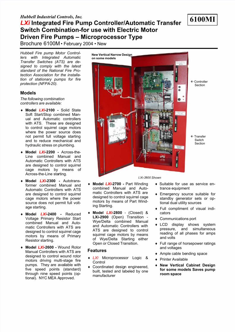
LXi-2800 Shown
New Vertical Narrow Design
on some models
Controller Section
Transfer Switch Section
7/23/2019 6100M Brochure
http://slidepdf.com/reader/full/6100m-brochure 2/4
Fire Pump Controllers with LXi Logic
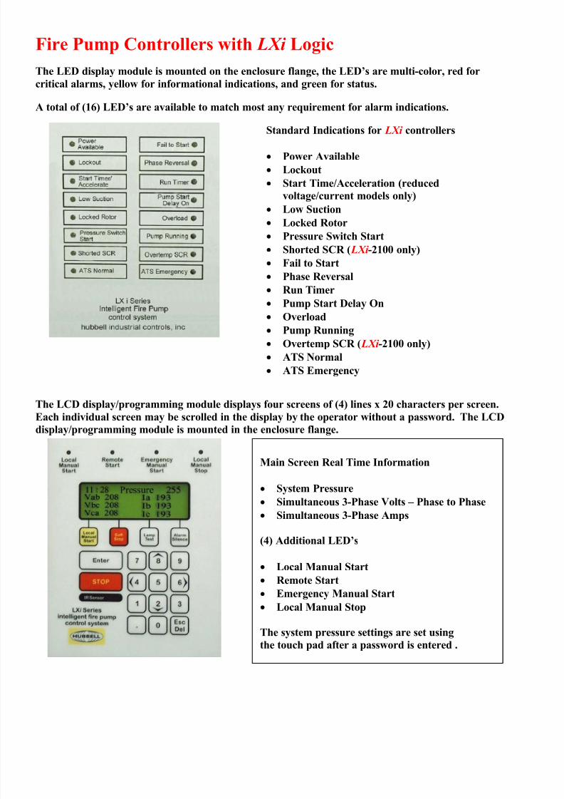
The LED display module is mounted on the enclosure flange, the LED’s are multi-color, red for
critical alarms, yellow for informational indications, and green for status.
A total of (16) LED’s are available to match most any requirement for alarm indications.
Standard Indications for LXi controllers
• Power Available
• Lockout
• Start Time/Acceleration (reduced
voltage/current models only)
• Low Suction
• Locked Rotor
• Pressure Switch Start
• Shorted SCR ( LXi -2100 only)
• Fail to Start
•
Phase Reversal• Run Timer
• Pump Start Delay On
• Overload
• Pump Running
• Overtemp SCR ( LXi -2100 only)
• ATS Normal
• ATS Emergency
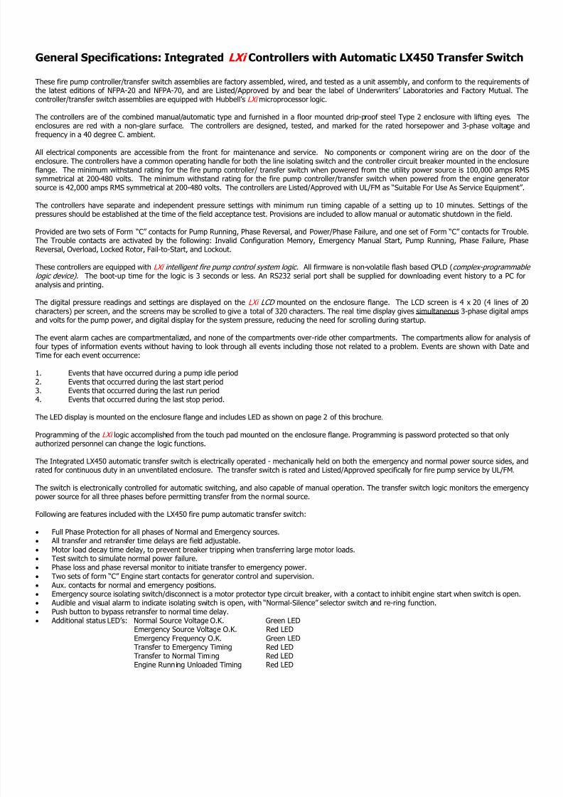
The LCD display/programming module displays four screens of (4) lines x 20 characters per screen.
Each individual screen may be scrolled in the display by the operator without a password. The LCDdisplay/programming module is mounted in the enclosure flange.
Main Screen Real Time Information
• System Pressure
• Simultaneous 3-Phase Volts – Phase to Phase
• Simultaneous 3-Phase Amps
(4) Additional LED’s
•
Local Manual Start
• Remote Start
• Emergency Manual Start
• Local Manual Stop
The system pressure settings are set using
the touch pad after a password is entered .
7/23/2019 6100M Brochure
http://slidepdf.com/reader/full/6100m-brochure 3/4
General Specifications: Integrated LXi Controllers with Automatic LX450 Transfer Switch
These fire pump controller/transfer switch assemblies are factory assembled, wired, and tested as a unit assembly, and conform to the requirements othe latest editions of NFPA-20 and NFPA-70, and are Listed/Approved by and bear the label of Underwriters’ Laboratories and Factory Mutual. Thecontroller/transfer switch assemblies are equipped with Hubbell’s LXi microprocessor logic.
The controllers are of the combined manual/automatic type and furnished in a floor mounted drip-proof steel Type 2 enclosure with lifting eyes. Theenclosures are red with a non-glare surface. The controllers are designed, tested, and marked for the rated horsepower and 3-phase voltage andfrequency in a 40 degree C. ambient.
All electrical components are accessible from the front for maintenance and service. No components or component wiring are on the door of theenclosure. The controllers have a common operating handle for both the line isolating switch and the controller circuit breaker mounted in the enclosureflange. The minimum withstand rating for the fire pump controller/ transfer switch when powered from the utility power source is 100,000 amps RMSsymmetrical at 200-480 volts. The minimum withstand rating for the fire pump controller/transfer switch when powered from the engine generatosource is 42,000 amps RMS symmetrical at 200-480 volts. The controllers are Listed/Approved with UL/FM as “Suitable For Use As Service Equipment”.
The controllers have separate and independent pressure settings with minimum run timing capable of a setting up to 10 minutes. Settings of thepressures should be established at the time of the field acceptance test. Provisions are included to allow manual or automatic shutdown in the field.
Provided are two sets of Form “C” contacts for Pump Running, Phase Reversal, and Power/Phase Failure, and one set of Form “C” contacts for TroubleThe Trouble contacts are activated by the following: Invalid Configuration Memory, Emergency Manual Start, Pump Running, Phase Failure, PhaseReversal, Overload, Locked Rotor, Fail-to-Start, and Lockout.
These controllers are equipped with LXi intelligent fire pump control system logic. All firmware is non-volatile flash based CPLD (complex-programmabl
logic device). The boot-up time for the logic is 3 seconds or less. An RS232 serial port shall be supplied for downloading event history to a PC foranalysis and printing.
The digital pressure readings and settings are displayed on the LXi LCD mounted on the enclosure flange. The LCD screen is 4 x 20 (4 lines of 20characters) per screen, and the screens may be scrolled to give a total of 320 characters. The real time display gives simultaneous 3-phase digital ampsand volts for the pump power, and digital display for the system pressure, reducing the need for scrolling during startup.
The event alarm caches are compartmentalized, and none of the compartments over-ride other compartments. The compartments allow for analysis ofour types of information events without having to look through all events including those not related to a problem. Events are shown with Date andTime for each event occurrence:
1. Events that have occurred during a pump idle period2. Events that occurred during the last start period3. Events that occurred during the last run period4. Events that occurred during the last stop period.
The LED display is mounted on the enclosure flange and includes LED as shown on page 2 of this brochure.
Programming of the LXi logic accomplished from the touch pad mounted on the enclosure flange. Programming is password protected so that onlyauthorized personnel can change the logic functions.
The Integrated LX450 automatic transfer switch is electrically operated - mechanically held on both the emergency and normal power source sides, andrated for continuous duty in an unventilated enclosure. The transfer switch is rated and Listed/Approved specifically for fire pump service by UL/FM.
The switch is electronically controlled for automatic switching, and also capable of manual operation. The transfer switch logic monitors the emergencypower source for all three phases before permitting transfer from the normal source.
Following are features included with the LX450 fire pump automatic transfer switch:
• Full Phase Protection for all phases of Normal and Emergency sources.• All transfer and retransfer time delays are field adjustable.• Motor load decay time delay, to prevent breaker tripping when transferring large motor loads.
•
Test switch to simulate normal power failure.• Phase loss and phase reversal monitor to initiate transfer to emergency power.• Two sets of form “C” Engine start contacts for generator control and supervision.• Aux. contacts for normal and emergency positions.• Emergency source isolating switch/disconnect is a motor protector type circuit breaker, with a contact to inhibit engine start when switch is open.• Audible and visual alarm to indicate isolating switch is open, with “Normal-Silence” selector switch and re-ring function.• Push button to bypass retransfer to normal time delay.• Additional status LED’s: Normal Source Voltage O.K. Green LED
Emergency Source Voltage O.K. Red LED Emergency Frequency O.K. Green LED Transfer to Emergency Timing Red LED Transfer to Normal Timing Red LED Engine Running Unloaded Timing Red LED
7/23/2019 6100M Brochure
http://slidepdf.com/reader/full/6100m-brochure 4/4
Hubbell Industrial Controls, Inc.a subsidiary of Hubbell Incorporated
4301 Cheyenne Drive, Archdale, N.C. 27263Telephone (336) 434-2800 • FAX (336) 434-2803
http://[email protected]
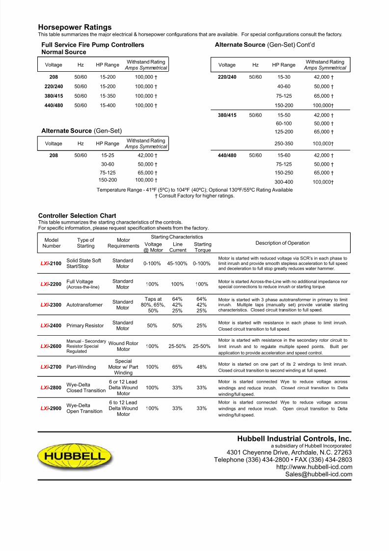
Horsepower RatingsThis table summarizes the major electrical & horsepower configurations that are available. For special configurations consult the factory.
Full Service Fire Pump ControllersNormal Source
Alternate Source (Gen-Set) Cont’d
Voltage Hz HP RangeWithstand Rating
Amps Symmetrical Voltage Hz HP Range
Withstand Rating Amps Symmetrical
208 50/60 15-200 100,000 † 220/240 50/60 15-30 42,000 †
220/240 50/60 15-200 100,000 † 40-60 50,000 †
380/415 50/60 15-350 100,000 † 75-125 65,000 †
440/480 50/60 15-400 100,000 † 150-200 100,000†
380/415 50/60 15-50 42,000 †
60-100 50,000 †
Alternate Source (Gen-Set) 125-200 65,000 †
Voltage Hz HP RangeWithstand Rating
Amps Symmetrical 250-350 100,000†
208 50/60 15-25 42,000 † 440/480 50/60 15-60 42,000 †
30-60 50,000 † 75-125 50,000 †
75-125 65,000 † 150-250 65,000 †
150-200 100,000 † 300-400 100,000†
Temperature Range - 41ºF (5ºC) to 104ºF (40ºC); Optional 130ºF/55ºC Rating Available† Consult Factory for higher ratings.
Controller Selection ChartThis table summarizes the starting characteristics of the controls.For specific information, please request specification sheets from the factory.
Starting CharacteristicsModel
Number Type of Starting
Motor Requirements Voltage
@ Motor Line
CurrentStartingTorque
Description of Operation
LXi -2100Solid State SoftStart/Stop
StandardMotor
0-100% 45-100% 0-100%Motor is started with reduced voltage via SCR’s in each phase tolimit inrush and provide smooth stepless acceleration to full speedand deceleration to full stop greatly reduces water hammer.
LXi -2200Full Voltage(Across-the-line)
Standard
Motor
100% 100% 100%Motor is started Across-the-Line with no additional impedance nor special connections to reduce inrush or starting torque.
LXi -2300 Autotransformer Standard
Motor
Taps at80%, 65%,
50%
64%42%25%
64%42%25%
Motor is started with 3 phase autotransformer in primary to limitinrush. Multiple taps (manually set) provide variable startingcharacteristics. Closed circuit transition to full speed.
LXi -2400 Primary Resistor Standard
Motor 50% 50% 25%
Motor is started with resistance in each phase to limit inrush.
Closed circuit transition to full speed.
LXi -2600Manual - SecondaryResistor SpecialRegulated
Wound Rotor Motor
100% 25-50% 25-50%
Motor is started with resistance in the secondary rotor circuit to
limit inrush and to regulate multiple speed points. Built per
application to provide acceleration and speed control.
LXi -2700 Part-WindingSpecial
Motor w/ PartWinding
100% 65% 48%Motor is started on one part of its 2 windings to limit inrush.
Closed circuit transition to second winding at full speed.
LXi -2800 Wye-DeltaClosed Transition
6 or 12 Lead
Delta WoundMotor
100% 33% 33%
Motor is started connected Wye to reduce voltage across
windings and reduce inrush. Closed circuit transition to Delta
winding/full speed.
LXi -2900Wye-DeltaOpen Transition
6 to 12 LeadDelta Wound
Motor 100% 33% 33%
Motor is started connected Wye to reduce voltage across
windings and reduce inrush. Open circuit transition to Delta
winding/full speed.