6.0l w12 engine in the audi a8l - audi klub polska most powerful 12-cylinder engine available in...
TRANSCRIPT

6.0L W12 Engine in theAudi A8L
SELF-STUDY PROGRAMCOURSE NUMBER 921403

Audi of America, Inc.Service TrainingPrinted in U.S.A.Printed 11/2004Course Number 921403
©2004 Audi of America, Inc.
All rights reserved. All informationcontained in this manual is based on thelatest information available at the time ofprinting and is subject to the copyrightand other intellectual property rights ofAudi of America, Inc., its affiliatedcompanies and its licensors. All rights arereserved to make changes at any timewithout notice. No part of this documentmay be reproduced, stored in a retrievalsystem, or transmitted in any form or byany means, electronic, mechanical,photocopying, recording or otherwise,nor may these materials be modified orreposted to other sites without the priorexpressed written permission of thepublisher.
All requests for permission to copy andredistribute information should bereferred to Audi of America, Inc.
Always refer to existing electronic serviceinformation for information that maysupersede any information included inthis booklet.
Trademarks: All brand names and productnames used in this manual are tradenames, service marks, trademarks, orregistered trademarks; and are theproperty of their respective owners.

1
Contents
TTTTThe self-studyhe self-studyhe self-studyhe self-studyhe self-study pr pr pr pr progrogrogrogrogram is not intended aam is not intended aam is not intended aam is not intended aam is not intended as as as as as aWWWWWorkshop Manual. orkshop Manual. orkshop Manual. orkshop Manual. orkshop Manual. VVVVValues given aralues given aralues given aralues given aralues given are onlye onlye onlye onlye only intended t intended t intended t intended t intended tooooohelp ehelp ehelp ehelp ehelp explain the subject matterxplain the subject matterxplain the subject matterxplain the subject matterxplain the subject matter and r and r and r and r and relate telate telate telate telate to theo theo theo theo thesofsofsofsofsoftwartwartwartwartware version applice version applice version applice version applice version applicable at the time ofable at the time ofable at the time ofable at the time ofable at the time ofpublicpublicpublicpublicpublication.ation.ation.ation.ation.
The self-study program contains information on designfeatures and functions.
Always use the latest technical publications whenperforming maintenance and repair work.
AttentionNoteNew
Introduction ............................................................................................................... 2
Technical Data, Cross Section, Longitudinal Section, W Design
Cylinder Block ........................................................................................................... 7
Cylinder Block and Crankcase ......................................................................... 9
Crankshaft ................................................................................................................13
Pistons/Connecting Rods .................................................................................16
Engine Mounting ...................................................................................................17
Engine Lubrication ...............................................................................................18
Cooling System .....................................................................................................22Electronically Controlled Cooling System, Map-Controlled Engine Cooling Thermostat (F265)Control Loop
Cylinder Head .........................................................................................................31
Camshaft Drive ......................................................................................................32Sealing of Timing Mechanism, Valve Timing/Camshaft Timing Control, Internal EGR, Valve Tim-ing/Adjustment Range, Control and Monitoring of Camshaft Position, Camshaft Adjusters,Function of Camshaft Adjusters, Electro-Hydraulic Control, Adjustment in Retard Direction,Adjustment in Advance Direction, Adjustment in Controlled Position
Belt Drive/Auxiliaries...........................................................................................46
Water-Cooled Alternator ...................................................................................47
Induction System .................................................................................................49
Engine Sub-Systems ...........................................................................................51
Engine Management Concept .......................................................................54
Service .......................................................................................................................77
Introduction
2
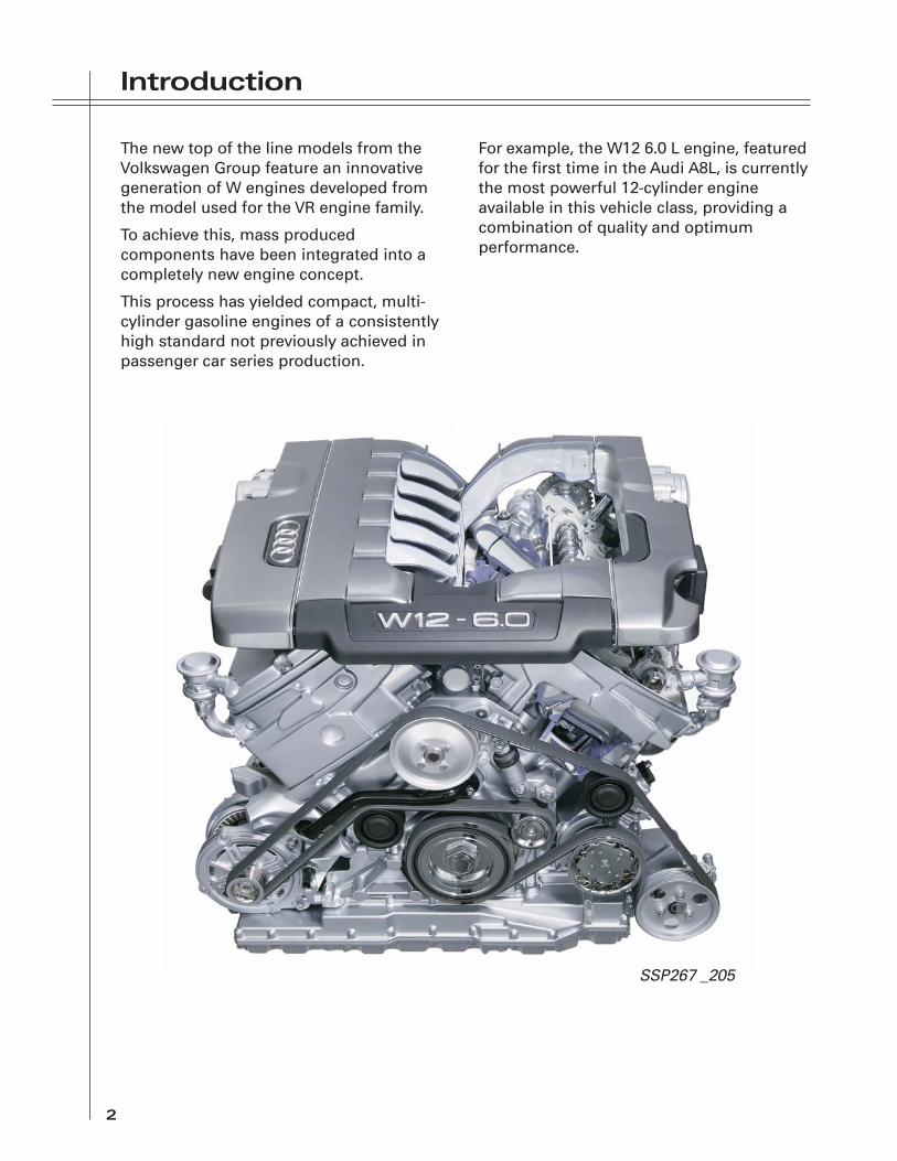
The new top of the line models from theVolkswagen Group feature an innovativegeneration of W engines developed fromthe model used for the VR engine family.
To achieve this, mass producedcomponents have been integrated into acompletely new engine concept.
This process has yielded compact, multi-cylinder gasoline engines of a consistentlyhigh standard not previously achieved inpassenger car series production.
For example, the W12 6.0 L engine, featuredfor the first time in the Audi A8L, is currentlythe most powerful 12-cylinder engineavailable in this vehicle class, providing acombination of quality and optimumperformance.
SSP267 _205

Introduction
3
TTTTTececececechnichnichnichnichnical Dal Dal Dal Dal Dataataataataata
Engine Code Letters: BSB
Design: W Engine with a V Angle of 15° and a Bank Angle of 72°
Capacity: 366 cu. in. (5998cm3)
Maximum Power: 450 hp (335 kW) at6200 RPM
Maximum Torque: 428 lb-ft (580 Nm)at 4000-4700 RPM*
Bore: 3.31 in. (84.0mm)
Stroke: 3.55 in. (90.27mm)
Compression Ratio: 11:1
Weight: 540 lb. (245 kg)
Fuel: PremiumUnleaded
Firing Order: 1-12-5-8-3-10-6-7-2-11-4-9
Ignition Interval: 60° Crankshaft
Engine Management: Motronic ME 7.1.1
Emission Standard: BIN 9 Federal
LEV I California
Engine Oil: VW 50301 (OW 30)
Oil Change Quantity: Approximately13 qt. (12.5 L) withFilter
Idling Speed: 560 RPM
* More than 90 % of Maximum Torque is available at 1800 RPM.
Premium unleaded 91 AK1/95 RON isrecommended for maximumperformance. Using regularunleaded results in reduced power.
0
30
60
90
120
150
180
210
240
270
300
330
0
60
120
180
240
300
360
420
480
540
600
660
1000 2000 3000 4000 5000 6000 7000
Engine Speed [RPM]
Pow
er [k
W]
Torq
ue
[Nm
]
SSP267_008

Introduction
4
CrCrCrCrCross Sectionoss Sectionoss Sectionoss Sectionoss Section
Special FSpecial FSpecial FSpecial FSpecial Featureatureatureatureatures of the es of the es of the es of the es of the W12W12W12W12W12
— 12-Cylinder, W Design Gasoline Engine— Aluminum Engine Block and Cylinder
Heads— Oil Supply with Wet Sump Lubrication
— Twin Overhead Camshafts with FourValves Each per Cylinder
— Roller-Type Rocker Fingers ValveOperation
— Infinitely Variable Timing Control forInlet and Exhaust Camshafts
SSP267_001

Introduction
5
Longitudinal SectionLongitudinal SectionLongitudinal SectionLongitudinal SectionLongitudinal Section
— Four Catalytic Converters forEmission Control
— Eight Oxygen Sensors for MixtureFormation Control and Emission ControlMonitoring
SSP267_002

Introduction
6
W DesignW DesignW DesignW DesignW Design
The new generation of W engines wasdeveloped to achieve a more compactdesign in relation to the number ofcylinders.
The W engines incorporate design featuresof the VR engine generation.
Combining two VR6 engines using a bankangle of 72° and a joint crankshaft createsa “V” V12 engine or a W12 engine.
V-engines with a small V angle are alsocalled VR engines. They benefit from thedesign advantages of both the smoothrunning in-line engine, and the shortdesign of the V-engine.
With a length of 20.2 in. (513mm) and awidth of 28.0 in. (710mm), the W12 enginehas the same space saving dimensions asthe V8 5V engine.
SSP267_082
60 - 90°15°
15° 15° 72°
In-line engine V-engine VR-engine(V-engine withsmall V-angle)
VR-engine VR-engine W-engine
+ =
Cylinder Block
7
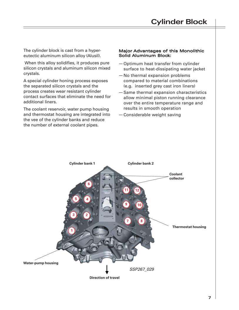
The cylinder block is cast from a hyper-eutectic aluminum silicon alloy (Alusil).
When this alloy solidifies, it produces puresilicon crystals and aluminum silicon mixedcrystals.
A special cylinder honing process exposesthe separated silicon crystals and theprocess creates wear resistant cylindercontact surfaces that eliminate the need foradditional liners.
The coolant reservoir, water pump housingand thermostat housing are integrated intothe vee of the cylinder banks and reducethe number of external coolant pipes.
MajorMajorMajorMajorMajor Advantages of this MonolithicAdvantages of this MonolithicAdvantages of this MonolithicAdvantages of this MonolithicAdvantages of this MonolithicSolid Solid Solid Solid Solid Aluminum BlocAluminum BlocAluminum BlocAluminum BlocAluminum Block:k:k:k:k:
— Optimum heat transfer from cylindersurface to heat-dissipating water jacket
— No thermal expansion problemscompared to material combinations(e.g. inserted grey cast iron liners)
— Same thermal expansion characteristicsallow minimal piston running clearanceover the entire temperature range andresults in smooth operation
— Considerable weight saving
Cylinder bank 1 Cylinder bank 2
Coolantcollector
Thermostat housing
Direction of travel
Water-pump housing
23
45
6
7 8
9 10
11 12
•
1
SSP267_029

Cylinder Block
8
The “fan” arrangement of the cylinder boreswith a V angle of 15°, and a bank angle of72°, creates a compact and rigid cylinderblock.
With a conventional layout, the very narrowV angle of 15° and the design of thecylinder block would affect the cylinderoverlap in BDC position.
As a result, the cylinders are offset withrespect to the axis of crankshaft rotation.The cylinder center axes do not coincidewith the crankshaft axis, but are offset tothe left or right.
This arrangement is known as cylinderoffset.
Together with an appropriate piston skirtdesign, the necessary clearance in BDCposition is achieved. (Refer to Section onPistons/Connecting Rods.)
The offset cylinder configuration requirescorresponding design modificationsaffecting both crankshaft group and valvetiming.
Cylinder bank 1Cylinder bank 2
15°
72°
15°
SSP267_034

Cylinder Block
9
-0.5
in. (1
2.5 m
m)
—
+—
+
Cylinder center axis/oddnumbered cylinders
Cylinder center axis/evennumbered cylinders
Line of crankshaft axis ofrotation parallel to cylindercenter axis
1 3 5
2 4 6
7 9 11
8 10 12
Bank 1
Bank 2
SSP267_098
The offset is as follows:
Odd-numbered cylinders - 0.5 in.12.5 mm (cyl. 1-3-5-7-9-11)
and
Even numbered cylinders + 0.5 in.+ 12.5 mm (cyl. 2-4-6-8-10-12)
SSP267_154

Cylinder Block and Crankcase
10
The crankcase is formed by the cylinderblock and the bearing support.
Cylinderblock
Bearing support
Top section ofsump
Sump
SSP267_137

Cylinder Block and Crankcase
11
The main bearing clearance is as constantas possible to satisfy noise levelrequirements over the entire operatingtemperature range. This is accomplished byusing a rigid bearing assembly.
The cast iron main bearing caps produce aform-fit in a rigid aluminum bearingsupport.
Each of the main bearings is only 0.59 in.(15mm) wide. Four permanently tightenedM8 bolts secure the main bearings.
The bearing support bolts to the cylinderblock, together with the top section of thesump and enhances the stability of theentire engine block.
A tapped crankshaft locating hole isprovided at the rear left of the bearingsupport.
By using of the appropriate locating pin, thecrankshaft is fixed in position at Number 1Cylinder TDC. The locating Pin is engagedin the crank web of Number 12 Cylinder.
Do not use the locating pin to providesupport, for example when looseningand tightening the central bolt.
Main bearing cap(cast iron)
Bearing support(aluminium)
Hole forlocating pin
Castwebs
SSP267_136

Cylinder Block and Crankcase
12
The method of attaching the engine blockto the transmission is unique.
The two upper transmission attachmentpoints protrude through the timing chaincover to provide a connection.
These connection pieces are fitted withradial seals.
Pulsation holes in the bearing blocksallow pressure equalization betweenthe cylinder chambers.
Cylinder bank 2
Radial seals
Cylinder bank 1
Timing chain cover
SSP267_107
SSP267_105
Crankshaft
13
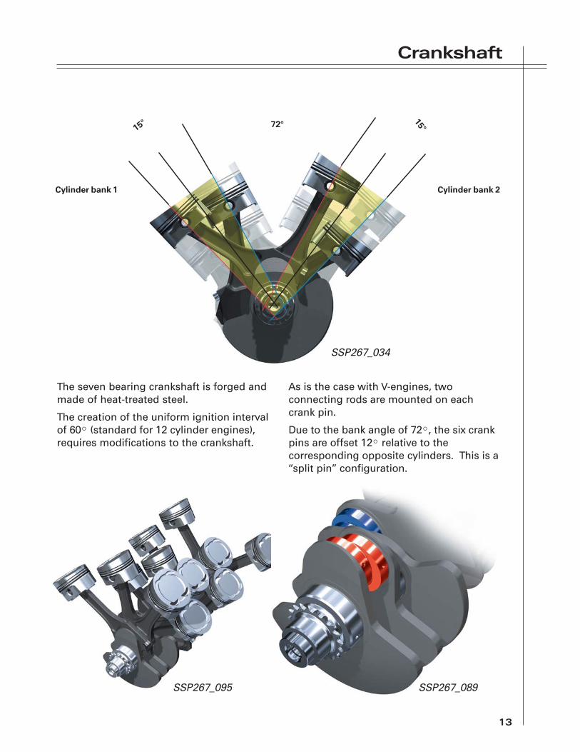
The seven bearing crankshaft is forged andmade of heat-treated steel.
The creation of the uniform ignition intervalof 60° (standard for 12 cylinder engines),requires modifications to the crankshaft.
As is the case with V-engines, twoconnecting rods are mounted on eachcrank pin.
Due to the bank angle of 72°, the six crankpins are offset 12° relative to thecorresponding opposite cylinders. This is a“split pin” configuration.
Cylinder bank 1 Cylinder bank 2
15° 72°
15°
SSP267_034
SSP267_095 SSP267_089

Crankshaft
14
+/+ Center points of corresponding crank pins
21,833°
Zyl.7Zyl.1
Zyl.12Zyl.6
Zyl.5
Zyl.2
Zyl.8
Zyl.10
Zyl.4Zyl.9
Zyl.3Zyl.11
12°
120°
120°
120°
SSP267_081
SSP267_080

Crankshaft
15
On a conventional 12-cylinder engine, thecrank pins are mutually offset by 120°.
With the W12 engine, the cylinder offsetmeans that there is an interval of 21.833°between the two crank pins on each plane.
As a result, the crank pin travel (angle)differs along the circular path from TDC toBDC and from BDC to TDC.
The two facing rows of cylinders in onebank oppose those in the other bank.
This explains the need for both theunconventional crank pin offset and thedifferences in valve timing for the evennumbered and odd numbered cylinders.
Cylinder bank 1 Cylinder bank 2
Cylinder axisl - Conrod lengthr - Crank radiusy - Offset at BDC
SSP267_102

Pistons/Connecting Rods
16
The pistons are made of a eutecticaluminum silicon alloy and are identical forboth rows of cylinders in each bank.
The joint flat cylinder head surface of thetwo rows of cylinders in each bank resultsin an asymmetrical combustion chamber.The piston crown is angled to create asymmetrical combustion chamber.
The installation direction is guided by thepiston crown angle.
The piston skirt is a shorter, stepped designto allow it to move between the bearingblocks.
Since the pistons move in aluminumcylinders, they have an electroplated ironcoating (Ferrostan).
Oil spray jets cool the pistons and preventthermal overloading.
The connecting rod upper end is atrapezoidal shape to reduce oscillatingmasses and distribute the combustion forcemore evenly.
Because of the compact design of cylinderblock and crankshaft, the connecting rodsare only 0.51 in. (13mm) wide at the largeconnecting rod eye.
As a result, the contact surface betweenconnecting rod cap and connecting rod isvery small. The bolted joint is machinedand fitted with anti-fatigue bolts.
Oil grooves in the connecting rod capfacilitate the exit of oil from the connectingrod bearing.
Compensation for the specific load actingon the connecting rod bearing is providedby a sputter bearing shell for theconnecting rod and a three-materialbearing shell in the connecting rod cap.
Sputtering is the application of bearingmaterial using electrical energy.
Since the bearings have no lugs, a specialtool must be used for connecting rodassembly.
Oil grooves
SSP267_140SSP267_031

Engine Mounting
17
Maximum ride comfort is achieved with theaid of two electrically-actuated enginemounts with hydraulic damping.
The solenoid valves are actuated by theECMs as a function of engine and vehiclespeed.
The left and right Electro-Hydraulic EngineMounting Solenoid Valves (N145 and N144)are actuated by Engine Control Modules(ECUs) 1 and 2 (J623 and J624) respectively.
The switching point is approximately 1100RPM when the vehicle is stationary,compared to less than 850 RPM at a speedof more than 4.5 mph (7 km/h).
Engine Mount/Cylinder Bank 1 with theRight Electro-Hydraulic Engine MountSolenoid Valve (N145)
Engine Mount/Cylinder Bank 2 with LeftElectro-Hydraulic Engine Mount SolenoidValve (N144)
SSP267_124

Engine Lubrication
18
The W12 engine lubrication system in the2005 A8L is a wet sump system. Earlier W12engines used a dry sump system.
The oil pump is mounted in the sump and ischain driven by the crankshaft.
CrankshaftOil Pump Drive Chain
Oil Sump(upper section)
Chain Tensioner
Oil Pump
Oil sump(bottom section)
Oil Pick-up
SSP267_200

Engine Lubrication
19
The oil filter housing and oil cooler moduleare mounted on the side of the engine thatincludes the water-cooled alternatormodule.
Another major difference with the lubrication system comparedto the earlier W12 versions is that the main bearings receive oilfrom the top of the central oil gallery rather than from thebottom.
CamshaftsBank 1
Oil retentionvalve
Oil retentionvalve
Tointermediate
shaft
Oil return
CamshaftsBank 2
Centraloil gallery
Riser
Oil return
Mainbearings
Main oilgallery
Oil supplyfrom sump
Piston spray jetswith oil-pressurevalves
To chaintensioner
Return
Supply SSP267_109

Engine Lubrication
20
The oil retention valves are located in therisers leading to the cylinder heads.
The valves prevent oil flowing back into thesump from the cylinder heads when theengine is turned off. This helps ensure arapid build up of oil pressure in the cylinderheads when the engine is restarted.
Cylinder head bank
Camshaft adjuster
Timing case
Camshaft
In the cylinder heads, the flow of oil isdistributed to the camshaft adjusters.Restrictors supply oil to the longitudinalgalleries, which supply the camshaftbearings and hydraulic elements.
At high engine speeds, the cylinder headsreceive large amounts of oil that flows backinto the sump through the oil returndrillings. The restrictors ensure that onlythe necessary amount of oil is fed in, thusreducing the oil pump drive power.
Direction of travel
SSP267_073
Oil retentionvalves
SSP267_133

Engine Lubrication
21
An oil separator for each cylinder bank ismounted under the intake manifold. Theseparators remove oil particles from theblow-by gases.
Blow-by gases are channeled to the oilseparator first through coarse-particleseparators integrated in the cylinder headsand lines.
A large portion of the oil is separated at theinlet to the oil separator by baffle plates.Three cyclone fine-separators operating inparallel separate the existing ultra-fine oildroplets and channel the blow-by gasesthrough a pressure control valve into thecylinder bank intake manifolds.
The separated oil collects in the bottompart of the separator and returns directly tothe cylinder heads.

Cooling System
22
The cooling system of the W12 engine ismade up of the following components:
– Water Pump in Cylinder Block/CrankcaseDriven Mechanically by Poly V Belt
– Map-Controlled Electrically OperatedContinued Coolant Circulation Pump
– After-Run Coolant Pump (V51) as backup for Mechanical Water Pump and forContinued Coolant Circulation
– Electronically Controlled CoolingSystem (Map-Controlled CoolantThermostat)
– Dual electric cooling fans– Map-Controlled Continued Coolant
Circulation– Water-Cooled Alternator
1 – Auxiliary Radiator2 – Thermostat for Auxiliary Radiator3 – Alternator4 – Engine Oil Cooler5 – Bleeder Screw6 – Bleeder Screw7 – Right and Left Regulating Valves8 – ATF Cooler9 – Expansion Tank10 – Map Controlled Engine Cooling
Thermostat11 – Coolant Temperature Sensor12 – Oil Cooler13 – Thermostat14 – Coolant Pump15 – After-Run Coolant Pump16 – Radiator17 – Heat Exchanger18 – Heat Exchanger
12
3
4
5
6
17
18
14 1316
1511
10
12
9
8
7
Right and LeftRegulator ValveN176 and N175
SSP267_202
Cooling System
23
The water pump distributes the coolant toeach of the two cylinder banks. The flow ofcoolant is split before being routedlongitudinally through the cylinder bank onthe inlet and exhaust ends.
Guide vanes ensure an even flow around allcylinders.
From the back of the cylinder head, part ofthe coolant flow for each cylinder bank iswithdrawn for alternator cooling and for theoil cooler.
Most of the coolant flows throughcalibrated holes on the exhaust end into thecylinder heads and passes transverselythrough them towards the inlet end.
The remainder of the coolant flow is routedinto the cylinder head on the inlet end.
The inner vee of the cylinder block has acoolant collector into which the coolantfrom both cylinder heads flows.
From there, the coolant flows through thelarge cooling circuit to the radiator, orthrough the small cooling circuit directly tothe thermostat housing and back to thewater pump.
Two heat exchangers, the alternator and oilcooler are integrated into the small coolingcircuit. The joint return pipe provides aconstant return flow to the water pump.

Cooling System
24
To radiator
Coolant collector
Thermostathousing
Coolantcollector
Supply from return pipeThermostat F265
From radiator
SSP267_038
SSP267_143

Cooling System
25
The After Run Coolant Pump (V51) has twofunctions:
1. To provide back up for the mechanicallydriven coolant pump at low enginespeeds and to ensure adequate coolantcirculation.The After Run Coolant Pump (V51) isactuated by the Coolant Pump Relay(J496) by ECU 1 (J623). Self-Diagnosisdoes not detect a blockage of the AfterRun Coolant Pump (V51).Map control is used in the After-RunCoolant Pump (V51) as necessary. Theparameters used are engine speed andcoolant temperature supplied by theEngine Coolant Temperature Sensor(G62).
Switching levels:Cut in: <840 RPM and >226°F (108°C)Cut out: >3000 RPM or <223°F (106°C)
2. To circulate the coolant duringcontinued coolant circulation.
OtherOtherOtherOtherOther C C C C Cooling Cirooling Cirooling Cirooling Cirooling Circuit Ccuit Ccuit Ccuit Ccuit Componentsomponentsomponentsomponentsomponents
A Non-Return Valve 1 stops the return ofcoolant to the radiator when the After-RunCoolant Pump V51 is operating.
A Non-Return Valve 2 in the inlet to theheating system heat exchangers preventsthe flow of coolant through the heatingsystem heat exchangers during continuedcoolant circulation.
To understand the need for Non ReturnValve 2, it is helpful to imagine thefollowing situation with no Non ReturnValve 2 in the circuit:
If a warm engine is briefly turned off at highambient temperatures, e.g. for re-fuellingafter a long road trip, continued coolantcirculation starts to operate. The After-RunCoolant Pump (V51) distributes the coolantthrough the open thermostat and themechanical water pump into the enginecooling jacket.
The coolant then flows back to the radiatorfrom the coolant collector. The coolant alsopasses through the permanently openreturn pipe and heating system return tothe pump/valve unit of the air conditioner(compared to when the engine is running).
As the Left and Right Heat RegulationValves (N175 and N176) of the pump/valveunit open, the flow would pass through theheating system heat exchangers and causethem to heat up if there were no non returnvalve fitted (because the circuit tcircuit tcircuit tcircuit tcircuit to ro ro ro ro radiatadiatadiatadiatadiatorororororwwwwwould be closed ofould be closed ofould be closed ofould be closed ofould be closed off on heating systemf on heating systemf on heating systemf on heating systemf on heating systemsupply end)supply end)supply end)supply end)supply end).
The combination of hot heating systemheat exchangers next to a cold, dampevaporator would cause enormoushumidification of the air in the airconditioner unit. Restarting (blower startup), would result in excessive misting of the(cold) windshield, a situation whica situation whica situation whica situation whica situation which Nonh Nonh Nonh Nonh NonReturn Return Return Return Return VVVVValve 2 is designed talve 2 is designed talve 2 is designed talve 2 is designed talve 2 is designed to pro pro pro pro preventeventeventeventevent.
A Non Return Valve 2 is defective when anexcessively high vent outlet temperature ispresent during a re-start after a brief stop(as described above).

Cooling System
26
ElectrElectrElectrElectrElectroniconiconiconiconicallyallyallyallyally C C C C Controntrontrontrontrolled Colled Colled Colled Colled Cooling Systemooling Systemooling Systemooling Systemooling System
To enhance efficiency, the coolanttemperature of the W12 engine iscontrolled electronically based on a map.
The coolant temperature regulationfunction should be viewed as a system.
The specified coolant temperature isimplemented with the aid of the electricallyheated Engine Cooling Thermostat (F265)and the Electric Fans operating as afunction of engine speed.
A particular feature of the W12 engine isthat there is only one Engine CoolantTemperature Sensor (G62) for the controlloop.
Engine speed, engine load, ambientEngine speed, engine load, ambientEngine speed, engine load, ambientEngine speed, engine load, ambientEngine speed, engine load, ambienttempertempertempertempertemperaturaturaturaturatureeeee (obtained from Intake AirTemperature Sensor [G42] in air massmeter) and engine oil temper engine oil temper engine oil temper engine oil temper engine oil temperaturaturaturaturatureeeee (fromEngine Oil Temperature Sensor [G8]) formthe basis for calculating a specifspecifspecifspecifspecifiediediediediedcoolant tempercoolant tempercoolant tempercoolant tempercoolant temperaturaturaturaturatureeeee.
The specified coolant temperature is alsoinfluenced by the knock control function,with the specified temperature beingreduced if possible in the event of knockingcombustion.
The specified coolant temperature variesbetween 221°F (105°C) in the lower partthrottle range and 194°F (90°C) at highengine loads or vehicle speeds in excess of112 mph (180 km/h).
The specified coolant temperature formsthe reference input variable for closed loopcontrol of the Map-Controlled EngineCoolant Thermostat (F265) and open loopcontrol of the Coolant Fan Valve (N313).
Map-Controlled Engine CoolingThermostat F265
Return flow from -Heating system -Oil cooler and- Alternator
From coolantcollector
Coolant pump
From radiator
SSP267_038
Cooling System
27
Map-CMap-CMap-CMap-CMap-Controntrontrontrontrolled Engine Colled Engine Colled Engine Colled Engine Colled Engine CoolingoolingoolingoolingoolingTTTTThermostat (F265) Chermostat (F265) Chermostat (F265) Chermostat (F265) Chermostat (F265) Controntrontrontrontrol Loopol Loopol Loopol Loopol Loop
The Map-Controlled Engine CoolingThermostat (F265) is actuated on a pulsewidth modulated basis with a duty cycle of0% to 100%.
ECM 1 (J623) uses the actualactualactualactualactual and specifspecifspecifspecifspecifiediediediediedcoolant temperature to calculate the Map-Controlled Engine Cooling Thermostat(F265) duty cycle and actuate it accordingly.
When de-energized (duty cycle 0%), thecontrol characteristic of the CoolantTemperature Regulator is at 221°F (105°C) atthe thermostat.
Given maximum (duty cycle 100%) of theMap-Controlled Engine Cooling Thermostat(F265), the control characteristic can bereduced to 194°F (90°C).
During continued coolant circulation, theduty cycle is 100%. As a result, the Map-Controlled Engine Cooling Thermostat(F265) opens at an appropriately lowtemperature, thus ensuring coolantcirculation by the After-Run Coolant Pump(V51).
If the Map-Controlled Engine CoolingThermostat (F265) (Heating Element) fails, afault message is stored in the fault memoryof ECM 1 (J623).
Hydraulic fan
After-RunPump V51
Engine Coolant TemperatureSensor-G62
Engine Control Module 1-J623
Auxiliary Engine CoolantPump Relay J496
Map-Controlled Engine CoolingThermostat F265
Coolant FanValve N313Drive Circuit Cooling Fan
Temperature Sensor G382
Diagnosis
SSP267_144

Cooling System
28
Coolant hose
Radiator
O-ring
Radiator fan V7
Retaining Pin
O-ring
Radiator fan V177
Coolant hose
Rubberinsulator
Radiator cowl
Rubberinsulator

Notes
29

Cylinder Head
30
The two cylinder heads in the W12 engineare based on the new cylinder head of theVR6 engine. The cylinder heads are bankspecific to permit camshaft drive from oneside.
Main features:
— Cross flow cylinder head with fourvalves –two overhead camshafts forinlet and exhaust
— Valve operation by roller type rockerfingers
— Hydraulic valve lifters— Infinitely variable timing control for inlet
and exhaust camshaft
Exhaust port
Camshaft forinlet valves
Camshaft forexhaust valves
Inlet port
SSP267_092
SSP267_091
Cylinder Head
31
The cylinder heads used in the VR6 enginewere modified as follows for the W12engine:
— Additional oil return channels onexhaust end due to greater inclinationof cylinder banks resulting from V angleof 72°.
— Adaptation of cylinder head water jacketto cross flow cooling concept.
The particular arrangement of the valvespermits the use of an inlet and an exhaustcamshaft and therefore separate camshaftadjustment.
The VR principle results in different inletand exhaust port lengths in the cylinderhead. This is offset by way of appropriateintake and exhaust system design, thusensuring virtually identical charge cycles inall cylinders.
Needle-bearing mountedroller-type rocker finger
SSP267_090

Camshaft Drive
32
The timing mechanism is located on theengine output end.
Timing mechanism drive is provided by asimplex chain running from the duplexchain sprocket mounted on the crankshaft,to the central intermediate shaft.
From there, one simplex chain each runs tothe left and right cylinder head to drive theinlet and exhaust camshafts in each case.
Cylinder bank 2 Cylinder bank 1
Chain tensioner/cylinder bank 2 Guide blade
Chain tensioner/cylinder bank 1
Primary Chaintensioner
Simplex chainsprocket
Intermediate shaft
Guide blade
Guide blade
SSP267_022

Camshaft Drive
33
Three spring-loaded hydraulic chaintensioners and the chain guides ensure thecorrect chain tension and smooth chainoperation (no ratchet mechanism).
Oil spray jets in the chain tensioner runnersprovide the necessary chain lubrication andcooling.
Chain sprocket forcamshafts/cylinder
bank 2
Intermediate shaft
Locating pin Sprocket forsimplex chain
Chain sprocket forcamshafts/cylinder
bank 1
SSP267_020
Camshaft Drive
34
Sealing of Sealing of Sealing of Sealing of Sealing of TTTTTiming Meciming Meciming Meciming Meciming Mechanismhanismhanismhanismhanism
SIS sealing (as of start of production)
A new feature is the use of the SealInjection System (SIS) for sealing the uppertiming chain covers.
The upper timing chain cover to lower coversealing surface has a groove, into which thesealing fluid is injected under pressure afterthe timing chain cover is installed.
The sealant is injected into the groove witha lubricating nipple.
Breather holes are provided at both ends ofthe groove to allow the escape of the airdisplaced by the sealant. Sealant isinjected into the groove until it emergeswithout any bubbles at both breather holes.
For details, refer to the current WorkshopManual.
Sealing surfacewith groove
Breather hole
Lower timing chain cover sealingsurface
Breather hole
Lubricating nipple
Upper timing chain cover of cylinder bank 1(Bottom view)
SSP267_062

Camshaft Drive
35
Silicone liquid seal (new)
A modified method of sealing the timingchain covers is gradually being introduced.
Sealing is performed in the usual way byapplying the sealant to the componentsbefore assembly.
The production of the sealing surfaces withgroove and chamfer is a new feature.
Both the groove and the chamfer improveadhesion and extend the service life of theseal.
For details, refer to the current WorkshopManual.
Chamfer
Groove
Chamfer
SSP267_197
SSP267_198

Camshaft Drive
36
VVVVValve alve alve alve alve TTTTTiming/Ciming/Ciming/Ciming/Ciming/CamshafamshafamshafamshafamshaftttttTTTTTiming Ciming Ciming Ciming Ciming Controntrontrontrontrololololol
The infinitely variable timing control for theinlet and exhaust camshafts on the W12engine permits “internal exhaust gasrecirculation.” This is why exhaust gasrecirculation is described here.
Exhaust GaExhaust GaExhaust GaExhaust GaExhaust Gas Recirs Recirs Recirs Recirs Recirculation (EGR)culation (EGR)culation (EGR)culation (EGR)culation (EGR)
Ever more stringent demands are beingmade of internal combustion enginesregarding power, torque, fuel economy andexhaust emission standards.
High combustion temperatures andpressures create unwanted NOx formationfrom the nitrogen contained in the intakeair.
Recirculating the exhaust gases to thecombustion chamber lowers thecombustion temperature and pressure, andleads to reduced NOx formation.
A distinction is made between external andinternal EGR.
With external EGR, the exhaust gas isrouted through a piping system with EGRvalve back into the intake port, where it isdrawn in again.
Key:1 Control unit2 EGR valve3 EGR temperature specification4 EGR pulse valve5 λ-probe/primary CAT6 Primary CAT
External exhaust-gasrecirculation
SSP267_108

Camshaft Drive
37
Internal EGRInternal EGRInternal EGRInternal EGRInternal EGR
With the W12 engine, an internal EGRsystem is used to reduce the NOx level.
Internal EGR involves controlling theoptimum setting of the residual gascomponent in the cylinders with an inletand exhaust valve timing adjustment.
The volume of exhaust gas re-circulateddepends on the amount of valve overlap.
Valve overlap is the angular range in whichthe inlet valve is already open before theexhaust valve closes.
The advantages of internal EGR include arapid reaction time (short distances), highrecirculation rate which can be achieved,good formation of the exhaust, fresh gasmixture, and fewer components.
Internal exhaust-gasrecirculation SSP267_117

Camshaft Drive
38
The graphs below illustrate the valveopening/closing times (maps) for differentload statuses with a warm engine. There isno valve overlap at idle and in the near idlerange.
There is no significant occurrence of NOx inthis range, thus eliminating the need forEGR. The precisely controlled charge cycleproduces a particularly smooth runningengine.
An appropriate valve overlap is set in thepart throttle range as a function of load andengine speed. This is the operating statusin which the highest level of NOx is found.The EGR reduces the NOx level and also hasa positive effect on fuel consumption.
In the full throttle range, the camshafts areset for maximum cylinder charge in linewith engine speed.
Inlet openingExhaust closingValve overlap
0
5
10
15
20
-5
-10
-15
-20
-25
n [ 1 /min ]
1000 2000 3000 4000 5000 6000
50 % load/operating temperature
°CS
bef
ore
TDC
°CS
aft
er T
DC
*
n [ 1 /min ]
1000 2000 3000 4000 5000 6000 -30
-20
-10
-0
10
20
30
°CS
aft
er T
DC
°CS
bef
ore
TDC
90 % load/operating temperature
* max. possible adjustment range/exhaust camshaft
* max. possible adjustment range/inlet camshaft
*
SSP267_083
SSP267_084

Camshaft Drive
39
VVVVValve alve alve alve alve TTTTTiming/iming/iming/iming/iming/Adjustment RangeAdjustment RangeAdjustment RangeAdjustment RangeAdjustment Range
Infinitely variable adjustment of the inletand exhaust camshafts is provided on theW12 engine to achieve optimum matchingof valve timing to the wide range of engineoperating points.
– The range of inlet camshaft adjustmentis 52° crankshaft.
– The range of exhaust camshaftadjustment is 22° crankshaft.
Optimum adjustment of valve timing isensured for the operating statuses…
…rapid catalytic converter warm up
…warm up phase
…operating temperature
…by way of separate maps.
The maps are referenced to engine speed,engine load and engine temperature (referto Page 38).
VVVVValve alve alve alve alve TTTTTiming*iming*iming*iming*iming*
Odd Numbered Cylinder Bank(Cylinders 1 - 3 - 5 - 7 - 9 - 11)
Io Advance 27° Before TDCRetard 25° After TDC
Ic Advance 183° After TDCRetard 235° After TDC
Eo Advance 235° Before TDCRetard 213° Before TDC
Ec Advance 20° Before TDCRetard 2° After TDC
*with 1mm valve lift and 0mm valveclearance
VVVVValve alve alve alve alve TTTTTiming*iming*iming*iming*iming*
Even Numbered Cylinder Bank(Cylinders 2 -4 -6 -8 -10 -12)
Io Advance 27° Before TDCRetard 25° After TDC
Ic Advance 188° After TDCRetard 240° After TDC
Eo Advance 230° Before TDCRetard 208° Before TDC
Ec Advance 20° Before TDCRetard 2° After TDC
Io = Inlet Openslc = Inlet ClosesEo = Exhaust OpensEc = Exhaust Closes
Because of the offset crankshaftgroup, the valve timing (Ic and Eo)differs for the even and oddnumbered cylinder banks.
12
11
10
9
8
7
6
5
4
3
2
1
080 160 OT240 320 400 480 560 640
Val
ve li
ft [m
m]
Crankshaft adjustment [°CS]SSP267_173

Camshaft Drive
40
CCCCControntrontrontrontrol and Monitol and Monitol and Monitol and Monitol and Monitoring of Coring of Coring of Coring of Coring of Camshafamshafamshafamshafamshaft Pt Pt Pt Pt Positionositionositionositionosition
A position sensor is located at eachcamshaft for control and monitoring of thecamshaft adjusters.
For exact determination of the camshaftadjustment, the basic settings (retardposition) of the four camshafts are learnedby the control modules (adaptation).
During adaptation, the solenoid valves arede-energized. The camshafts are moved toretard position (basic setting) both by thesetting of the solenoid valves and thedirection of pull exerted by the chain.
The position of the camshaft positionsensor signals relative to the engine speedsensor reference mark (actual values), isstored as basic position and compared tothe specified values. This provides thebasic values for camshaft timing control.
A distinction is made between basic andfine adaptation.
Basic adaptation is always implementedafter the ECM is de-energized (no Terminal30) or erasing of DTCs.
After starting the engine, the camshaftsbriefly remain in the basic position until theexact position of the camshafts withrespect to the crankshaft has beenestablished.
If the camshafts are already in basicposition (valves de-energized) and thecoolant temperature is greater than 185°F(85°C), and assuming basic adaptation hasbeen implemented, fine adaptation isalways performed breifly several times (forapproximately one second) after startingthe engine.
Adaptation of the inlet camshafts takesplace at idle or in the near idle range.
Adaptation of the exhaust camshafts takesplace in the engine speed range between1200 and 2000 RPM and at low engine load.
The two ECMs implement independentadaptation of the camshaft positions. Thecamshaft timing control function isdisabled if adaptation is not performedsuccessfully.
Camshaft PositionSensor 4/cylinderbank 2 G382
Camshaft PositionSensor 2/cylinderbank 2 G382
Camshaft PositionSensor/cylinderbank 1 G40
Camshaft PositionSensor 3/cylinderbank 1 G300
SSP267_125

Camshaft Drive
41
CCCCCamshafamshafamshafamshafamshaft t t t t AdjustersAdjustersAdjustersAdjustersAdjusters
The mode of operation of the camshaftadjusters is based on a hydraulic vane-typerotary motor.
The illustration below shows the position ofthe camshafts with the engine idling atoperating temperature.
The inlet camshaft is in retard position,whereas the exhaust camshaft is inadvance position. When the engine is
started, the exhaust camshafts are initially“drawn” towards retard position due to thelow oil pressure and direction of chain pull.
When the solenoid valves are de-energized,the inlet and exhaust camshafts alsoassume the retard position.
Cylinder bank 2 Cylinder bank 1
AdvanceRetard
E
Advance
RetardRetard
Retard
E
Advance
Advance
II
EEEEE - Exhaust adjustment range 11° (22° crankshaft)
IIIII - Inlet adjustment range 26° (52° crankshaft)
SSP267_128

Camshaft Drive
42
Pressurechamber
A
B
A
B
Pressurechamber
FFFFFunction of Cunction of Cunction of Cunction of Cunction of Camshafamshafamshafamshafamshaft t t t t AdjustersAdjustersAdjustersAdjustersAdjusters
The camshaft adjuster consists of the five-vane rotor (connected to the camshaft), thestator (connected to the chain sprocket) andthe electro-hydraulic control unit.
The arrangement of the oil drillings in therotor creates a pressure chamber on eitherside of each vane (pressure chambersA and B).
When oil pressure is applied to pressurechamber A, the rotor turns clockwise (inrelation to the stator). In terms of thecamshaft, this represents the “retard”position.
When oil pressure is applied to pressurechamber B, the rotor turns counter-clockwise (in relation to the stator). Interms of the camshaft, this represents the“advance” position.
The term “stator” may seemmisleading. The stator is driven by thetiming chain which causes it to rotateand thus it is not actually “static” initself. It does however always maintainthe same angular position with respectto the crankshaft. The rotor turnsrelative to the crankshaft and thus tothe stator.
Appropriate pressure control in the twopressure chambers (A and B) makes itpossible to set any arbitrary positionbetween the two stops, thus providinginfinitely variable camshaft timing control.
SSP267_054
SSP267_053

Camshaft Drive
43
Timing case
Hydraulic control unit
ElectrElectrElectrElectrElectro-Hydro-Hydro-Hydro-Hydro-Hydraulic Caulic Caulic Caulic Caulic Controntrontrontrontrololololol
Pressurized oil is conveyed withoutrestrictions, to the control unit/solenoidvalves through two separate holes. Non-return valves in the solenoid valve inletsboost the system function at low oilpressure. Depending on how they areactuated, the solenoid valves route thepressurized oil to pressure chambers A andB of the rotary motors.
The control unit also acts as the housing forthe camshaft rotary bushes, forming thelink between solenoid valve and rotarymotor.
ECMs 1 and 2 (J623/J624) actuate CylinderBank 1 Valve 1 for Camshaft Adjustment(N205)/Valve 2 for EGR (N213), CamshaftAdjustment Valve 1 (N318) and CylinderBank 2 Solenoid Valve 2 for CamshaftAdjustment (N208)/Camshaft AdjustmentValve 1 (N318).
The solenoid valves are proportional valves.They are PWM actuated and convert thecontrol current into a switch positiondepending on the pulse width. The valvesare identical. The wiring harnessconnectors are different shapes and colorsto make them easier to service.
The position to which the solenoid valvesswitch when de energized is the same forboth the inlet and exhaust rotary motors.
The setting of the solenoid valves is defined(by spring force), so that the oil pressure isapplied to Pressure Chamber A. The inletand exhaust camshafts are therefore in theretard position.
If there is no or only marginal oil pressure,the camshafts are also set to the retardposition because of the chain pull.
SSP267_133

Camshaft Drive
44
Non-return valvePort (A)
Non-return valve Port (B)
Oil supply Oil drain
Adjustment in Retard DirAdjustment in Retard DirAdjustment in Retard DirAdjustment in Retard DirAdjustment in Retard Directionectionectionectionection
Adjustment in Adjustment in Adjustment in Adjustment in Adjustment in Advance DirAdvance DirAdvance DirAdvance DirAdvance DirectionectionectionectionectionSSP267_127
SSP267_126

Camshaft Drive
45
Non-return valve
Adjustment in CAdjustment in CAdjustment in CAdjustment in CAdjustment in Controntrontrontrontrolled Polled Polled Polled Polled Positionositionositionositionosition
The camshaft adjusters are equipped withan auxiliary coil spring attached to theadjuster housing. This spring helps to turnthe internal rotor of the adjuster in the"advance" direction.
SSP267_146

Belt Drive/Auxiliaries
46
Water pump
Idler wheel
Air-conditioningcompressor
Tandem oilpump
Tensioning roller
Crankshaft
Alternator
Belt Drive/Belt Drive/Belt Drive/Belt Drive/Belt Drive/AAAAAuxiliariesuxiliariesuxiliariesuxiliariesuxiliaries
Idler wheel
Water-Cooled Alternator
47
Alternators generate a high level of currenteven at low speeds. With air-cooledalternators, the cooling output is a functionof speed, which results in extreme heatingof the components during high poweroutput combined with low speed. Highambient temperatures add to this situation.
To alleviate this condition, a water-cooled190 alternator with a power output of2660W is used on the Audi A8L W12.
The water-cooled alternator has a waterjacket that surrounds the stator windingand the surface of the rectifier diodes andregulator mounting plate.
The alternator water jacket is incorporatedinto the engine cooling circuit and providescooling in all operating ranges, especiallyhigh power output at low speeds. The“open” design pulley provides an exchangeof cooling air for the claw-pole rotor. Sincethe air vortex of the claw-pole rotor isenough, a fan impeller is not necessary.
Permanent magnets between the rotorsegments enhance the magnetic fluxbetween the claw-pole rotor and statorwinding and increase efficiency. The polesof the permanent magnets have the samepolarization as the rotor segments.
The permanent magnets are relatively weakto minimize self-excitation and to allowregulation of the alternator voltage.
SSP268_097

Water-Cooled Alternator
48
Water jacket
Permanent magnets between the rotor segments enhance themagnetic flux (from the claws to the stator windingand vice versa), thus preventing stray flux between the individualpoles.
MorMorMorMorMore e e e e Advantages of Advantages of Advantages of Advantages of Advantages of WWWWWateraterateraterater-C-C-C-C-CooledooledooledooledooledAlternatAlternatAlternatAlternatAlternatorsorsorsorsors
— Quiet operation results from eliminatingthe fan impeller. There is noaerodynamic flow noise.
— Smooth running due to rigid, encloseddesign of alternator housing.
— Eliminating the fan impeller results in adecrease in drive power required andyields up to 5% more efficiency (as afunction of speed).
— Recovery of heat lost to engine coolingcircuit during warm-up phase.
— High performance level due to constantcooling over entire speed range.
— Reduced susceptibility to high ambienttemperatures.
SSP268_050
SSP268_048

Induction System
49
The intake system of the W12 features twoMass Airflow Sensors and two ThrottleBody Control Modules. Each sensor andthrottle body is fed fresh air from its own airbox and filter.
Throttle Body Control Module J544 Throttle Body Control Module J338
The manifold itself is a split designcomprised of an upper and lower half. Theupper portion must be removed beforeservicing the ignition coils or fuel injectorsis possible. The upper half can be furtherdisassembled into three separate pieces.
Separate crankcase ventilation boxes aremounted under the upper half of the intakemanifold.

Induction System
50
Intake Manifold(upper section)
Pressure Control Valve for CrankcaseBreather System (left bank)
Intake Manifold(lower section)
Always refer to the repair informationwhen removing and installing the intakemanifold.
Gaskets and seals must always bereplaced. Special bolt tighteningprocedures must also be followed.

Engine Sub-Systems
51
Advantages of metal substrate over ceramicsubstrate catalytic converters:
— The lower flow resistance results in alower exhaust backpressure andenhanced power yield.
— The catalytic converter responsetemperature is reached faster becauseof the lower heat capacity of the metalsubstrate and reduces unwantedemissions.
Mixture composition and emission controlare monitored by four independent controlloops using eight heated oxygen sensors.
Each primary catalytic converter is assigneda wide band oxygen sensor as upstreamprobe and a step change probe asdownstream sensor. Operation of the wideband oxygen sensor is described inSSP 247.
Cylinder bank 2 Cylinder bank 1
Exhaust bank 1Cylinders 1-3
Exhaust bank 2Cylinders 4-6
To main catalyticconverters
Exhaust bank 4Cylinders 10-12
Exhaust bank 3Cylinders 7-9
SSP268_079

Engine Sub-Systems
52
Exhaust FlapsExhaust FlapsExhaust FlapsExhaust FlapsExhaust Flaps
The W12 engine has two exhaust flaps. As afunction of engine load, engine speed andvehicle speed, the ECM 1 (J623) switchesthe exhaust flap on the right side and ECM2 (J624) switches the exhaust flap on theleft side.
The exhaust flaps are closed at idle, in thelower part throttle range and enhancesilencer efficiency.
When parameters exceed defined values,the exhaust flaps open and reduce exhaustbackpressure.
The comfort level is maintained in low loadranges without increasing exhaustbackpressure in higher load ranges.
OperOperOperOperOperation/Cation/Cation/Cation/Cation/Controntrontrontrontrol of Exhaust Flapol of Exhaust Flapol of Exhaust Flapol of Exhaust Flapol of Exhaust Flap
Spring force keeps exhaust flaps open inde-energized and depressurized conditions.
This ensures the free discharge of exhaustgases if the system fails and preventsreduced performance and/or damage to thecomponents.
Actuation of Exhaust Flap Valve (N321) orExhaust Flap Valve 2 (N322) applies vacuumto the vacuum unit and closes the exhaustflap by overcoming the spring force.Switching conditions for opening ofexhaust flaps is as follows:
Vehicle Speed > 3 mph (5 km/h)Engine Load > 50%Engine Speed > 2500 RPM
Non-return valve
Flap open
Energized
De-energized
Non-return valve
Vacuum reservoir
Intakemanifold
J623
Flap closed
VacuumAtmospheric pressure
J623
Vacuum reservoir
Intakemanifold
SSP268_179
SSP268_180

Notes
53
Engine Management Concept
54
The Engine Management System for theW12 engine, Motronic ME7.1.1, is a twocontrol module concept.
Two control units are identical and each isassigned to one cylinder bank. The twocylinder banks are considered separateengines.
However, certain sub-functions arecommon to ECM 1 (J623) for Cylinder Bank 1and Engine Control Module 2 (ECM 2) (J624)for Cylinder Bank 2
Control unit/cylinder bank assignmentidentification is provided by pin encoding inthe wiring harness. To provide a cleardistinction, the wiring harness to eachcontrol unit is wrapped with differentcolored tape.
Pin encoding means that:
— Pin 49 of ECM 1 (J623) is connected toTerminal 15.
— Pin 49 of ECM 2 (J624) is connected toTerminal 31.
Because of the Twin Control Unit Concept,both control units must:
— have the same software version.— be matched to the Cruise Control
System (CCS).— be matched to the Immobilizer.— be viewed as separate entities for self-
diagnosis.— have the same encoding.
SSP268_129
BOSCH BOSCHBOSCH BOSCH
Engine control module 2 J624 Engine control module 1 J623

Engine Management Concept
55
OnlyOnlyOnlyOnlyOnly ECM 1 (J623) per ECM 1 (J623) per ECM 1 (J623) per ECM 1 (J623) per ECM 1 (J623) perffffforms theorms theorms theorms theorms thefffffollowing functions.ollowing functions.ollowing functions.ollowing functions.ollowing functions.
— Determination of specified speed valuesfor idling speed control
— Coolant temperature regulation,continued coolant circulation, actuationof continued After-Run Coolant Pump(V51)
— Provision of CAN data for drive systemCAN
— Actuation of Fuel Pump Relay (J17) andMotronic ECM Power Supply Relay(J271)
— Control of exhaust flap
ECU 1 (J623) prECU 1 (J623) prECU 1 (J623) prECU 1 (J623) prECU 1 (J623) processes the focesses the focesses the focesses the focesses the followingollowingollowingollowingollowinginterinterinterinterinterfffffaces.aces.aces.aces.aces.
— Brake Light Switch F/Brake Pedal Switch(F47)
— Engine Coolant Temperature Sensor(G62)
— Cruise Control Switch (E45)— A/C High Pressure Signal from A/C
Pressure Switch (F129)— Terminal 50 Signal— Engine Speed SignalOnlyOnlyOnlyOnlyOnly ECM 2 J624 per ECM 2 J624 per ECM 2 J624 per ECM 2 J624 per ECM 2 J624 perffffforms theorms theorms theorms theorms thefffffollowing functions.ollowing functions.ollowing functions.ollowing functions.ollowing functions.
— Misfire Detection— Processing of Engine Oil Temperature
Sensor (G8) signal SSP268_148
K50
Engine control module 2 J624 Engine control module 1 J623
Terminal 31Terminal 15

Engine Management Concept
56
System LayoutSystem LayoutSystem LayoutSystem LayoutSystem Layout
Heated oxygen sensor 2 -G39/-G108
Throttle position sensor-G79/-G185
Oxygen sensors -G130/-G131
Mass airflow sensor -G70Intake airtemperaturesensor -G42
Throttle Valve Control Module 1 -J338
Engine ControlModule 1 -J623
Cruise ControlSwitch -E45
Drive circuit coolingfan temperaturesensor -G382
Additional signals
Camshaftposition sensors-G40 (inlet)-G300 (exhaust)
Knock Sensors 1 and2 -G61/G66
Brake Light Switch -FBrake Pedal Switch -F47
Engine speedsensor -G28
Engine coolanttemperature sensors-G2/-G62
Pin 49 toTerminal 15
DiagnosticConnection
DriveSystem CAN
Throttle Valve ControlModule 2 -J544
Engine speed sensor -G28
Heated oxygen sensors -G285/-G286
Oxygen sensors -G287/-G288
Additionalsignals
Mass airflow sensor 2 -G246Intake Air Temperature Sensor 2 -G299
Engine OilTemperature
CamshaftPosition Sensors-G163 (inlet)-G301 (exhaust)
Engine controlmodule 2 -J624
Knock sensors 3 and4 -G198/-G199 Pin 49 to ground

Engine Management Concept
57
Secondary air injectionpump relay 2 -J545 withsecondary air injectionpump motor 2 -V189
Throttle Valve ControlModule 1 -J338
Secondary-air injectionsolenoid valve -N112
Ignition coils with poweroutput stage -N70, 127, 291,292, 323, 324
Evaporative emissioncanister purge regulatorvalve -N80
Fuel injectors -N30, 31, 32, 33,83, 84
Map-controlledEngine CoolingThermostat -F265
Motronic EngineControl ModulePower SupplyRelay -J271
Additionalsignals
Right Electro-hydraulic enginemount solenoidvalve -N145
Exhaust flapvalve -N321
Valve 1 forCamshaftadjustment-N205 (inlet)-N318 (exhaust)
Additionalcoolant pumprelay -J496 withafter-run coolantpump -V51
Secondaryair injectionpump relay -J299 withsecondary airinjectionpump motor-V101
Coolant fanvalve -N313
Fuel pumprelay -J17with fuelpump -G6
Relay forradiatorfan after-run -J397
Throttle valve controlmodule 2 -J544
Ignition coils withpower output stages -N325, N326, N327,N328, N329, N330
Fuel Injectors -N85, 86, 299, 300,301, 302
Secondary airinjection solenoidvalve 2 -N320
Additionalsignals
Left electro-hydraulic enginemount solenoidvalve -N144
Evaporative emissioncanister purge regulatorvalve 2 -N333
Valve 2 for camshaftadjustment-N208 (inlet)-N319 (exhaust)

Engine Management Concept
58
Sensors/Sensors/Sensors/Sensors/Sensors/ActuatActuatActuatActuatActuatorsorsorsorsors
BlocBlocBlocBlocBlock Diagrk Diagrk Diagrk Diagrk Diagram Motram Motram Motram Motram Motronic ME7.1.1onic ME7.1.1onic ME7.1.1onic ME7.1.1onic ME7.1.1
A Battery
E45 Cruise Control Switch
F Brake Light Switch
F47 Brake Pedal Switch
F265 Map-Controlled Engine Cooling Thermostat
G2 Coolant Temperature Sensor
G6 Fuel Pump
G8 Oil Temperature Sensor
G28 Engine Speed Sensor
G39 Heated Oxygen Sensor
G40 Camshaft Position Sensor
G42 Intake Air Temperature Sensor
G61 Knock Sensor 1
G62 Engine Coolant Temperature Sensor
G66 Knock Sensor 2
G70 Mass Air Flow Sensor
G79 Throttle Position Sensor
G108 Heated Oxygen Sensor 2
G130 Oxygen Sensor
G131 Oxygen Sensor 2
G163 Camshaft Position Sensor 2
G185 Sensor 2 for Accelerator Pedal Position
G186 Throttle Drive (Power Accelerator Actuation)
G187 Angle Sensor 1 for Throttle Drive (PowerAccelerator Actuation)
G188 Angle Sensor 2 for Throttle Drive (PowerAccelerator Actuation)
G198 Knock Sensor 3
G199 Knock Sensor 4
G246 Mass Airflow Sensor 2
G285 Heated Oxygen Sensor 3
G286 Heated Oxygen Sensor 4
G287 Oxygen Sensor 3
G288 Oxygen Sensor 4
G296 Throttle Drive 2
G297 Angle Sensor 1 on Throttle Valve Drive 2
G298 Angle Sensor 2 for Throttle Valve Drive 2
G299 Intake Air Temperature Sensor 2
G300 Camshaft Position Sensor 3
G301 Camshaft Position Sensor 4
G382 Drive Circuit Cooling Fan Temperature Sensor
J17 Fuel Pump Relay
J271 Motronic ECU Power Supply Relay
J299 Secondary Air Injection Pump Relay
J338 Throttle Valve Control Module
J397 Relay for Radiator Fan After Run
J496 Auxiliary Engine coolant Pump Relay
J544 Throttle Valve Control Module 2
J545 Secondary Air Injection Pump Relay 2
J623 ECM 1
J624 ECM 2
M9 Left Brake Light Bulb
M10 Right Brake Light Bulb
N30 Cylinder 1 Fuel Injector
N31 Cylinder 2 Fuel Injector
N32 Cylinder 3 Fuel Injector
N33 Cylinder 4 Fuel Injector
N70 Ignition Coil 1 with Power Output Stage
N80 Evaporative Emission Canister PurgeRegulator Valve
N83 Cylinder 5 Fuel Injector
N84 Cylinder 6 Fuel Injector
N85 Cylinder 7 Fuel Injector
N86 Cylinder 8 Fuel Injector
N112 Secondary Air Injection Solenoid Valve
N127 Ignition Coil 2 with Power Output Stage
N144 Left Electro Hydraulic Engine Mount SolenoidValve
N145 Right Electro Hydraulic Engine MountSolenoid Valve
N205 Camshaft Adjustment Valve 1
N208 Camshaft Adjustment Valve 2
N291 Ignition Coil 3 with Output Power Stage
N292 Ignition Coil 4 with Output Power Stage
N299 Cylinder 9 Fuel Injector
N300 Cylinder 10 Fuel Injector
N301 Cylinder 11 Fuel Injector
N302 Cylinder 12 Fuel Injector
N313 Coolant Fan Valve
N318 Camshaft Adjustment Valve 1
5959595959
Engine Management CEngine Management CEngine Management CEngine Management CEngine Management Conceptonceptonceptonceptoncept
31
S S S SS S
F265
S S S
1515
X
1530
N318 N205 N112 N321
M
M
F47
M10
G40 G300G66 G61
J17
N145 N80
J299
V101
31
G6
N31 N32N33 N83N84
G70/G42
+-
mL
G131
J623
G28G62
C
N30
D
N313
G2
F
D
B
G108
-
B
49
QP
15
N127
N291
N292
N323
N324
λλPZ
NZ
M9
+ +
+
-
A
XC
+
G39
λ
G130
E
A
PZ
NZ
D C
N70
G186 G187
M
G188
+ -
J338
01 22a
0,2a

6060606060
Engine Management CEngine Management CEngine Management CEngine Management CEngine Management Conceptonceptonceptonceptoncept
31
3015
X
S
G382
S
G8
S S
E
G246/G299
C
mL
G163 G301
N144 N319 N320
M
N208
J545
V189
31
N86N299
N302N301N300
G296 G297
M
G298
N333
G198 G199
t°
M
J496
V51
31
J271
QP
N325
J544
J397
A
λλPZ
NZ
G288G79 G185
+ - + -
1 2 3N326
N327 N328
+ +
N85
+ -
D E
X
J624
N329
N330
BB
-+-
G285 G286
PZ
NZ
λ
G287
4
8 9
65 7
E
D C
49
C

Engine Management Concept
61
N319 Camshaft Adjustment Valve 2
N320 Secondary Air Injection Solenoid Valve 2
N321 Exhaust Flap 1 Valve
N323 Ignition Coil 5 with Final Power Output Stage
N324 Ignition Coil 6 with Final Power Output Stage
N325 Ignition Coil 7 with Final Power Output Stage
N326 Ignition Coil 8 with Final Power Output Stage
N327 Ignition Coil 9 with Final Power Output Stage
N328 Ignition Coil 10 with Final Power OutputStage
N329 Ignition Coil 11 with Final Power OutputStage
N330 Ignition Coil 12 with Final Power OutputStage
N333 Evaporative Emission Canister PurgeRegulator Valve
V51 After-Run Coolant Pump
V101 Secondary Air Injection Pump Motor
V189 Secondary Air Injection Pump Motor 2
Additional SignalsAdditional SignalsAdditional SignalsAdditional SignalsAdditional Signals
1 Terminal 50
2 To Relay for Radiator Fan After-Run (J397)
3 AC High Pressure Signal from A/CPressure
Switch (F129) (High Pressure Switch)
4 AC Requirement Signal (from A/C ControlHead [E87])
5 Compressor “ON/OFF” Signal
6 Crash Signal
7 Engine Speed Signal
8 CAN Low/Drive
9 CAN High/Drive
Power Supply fromFuel Pump Relay (J17)
A
C
B
X
E
D
Motronic ECM Power
Supply Relay (J271)
Connections withinBlock Diagram
CCCCColorolorolorolorolor C C C C Codeodeodeodeode
= Input Signal
= Output Signal
= Positive Supply
= Ground
= CAN Bus

Engine Management Concept
62
Special FSpecial FSpecial FSpecial FSpecial Featureatureatureatureatures ofes ofes ofes ofes ofMotrMotrMotrMotrMotronic ME7.1.1onic ME7.1.1onic ME7.1.1onic ME7.1.1onic ME7.1.1
The Motronic ME7.1.1 is an advancedversion of the Motronic ME7.1 and hasthese features:
— Larger computer capacity because ofnew computer-bound sub-functions
— Extension of control unit activities afterturning off the ignition with the aid ofmain relay concept
— Infinitely variable adjustment of inletand exhaust camshafts
— Designed to suit new broad bandoxygen sensor upstream of catalyticconverter
— Designed for coolant temperatureregulation
— Enhanced evaluation of signals fromEngine Coolant Temperature Sensor(G62)
— Management of additional and newCAN messages
G62 EvaluationG62 EvaluationG62 EvaluationG62 EvaluationG62 Evaluation
Precision sensing of the coolanttemperature over a broad temperaturerange is very important.
Precise determination of the coolanttemperature in the lower operatingtemperature range is required for coldstarting and subsequent warm up.
Coolant temperature regulation demandsexact recognition of the coolanttemperature in the upper operatingtemperature range.
The characteristic curve of the EngineCoolant Temperature Sensor (G62) (NTCSender) is steep over the temperature rangeto be recorded -- approximately 86°F (30°C)to 248°F (120°C).
At the same time, the coefficient ofresistance ranges from approximately25,000 Ohms to approximately 115 Ohms.The change in resistance per Kohm variesconsiderably at low and high temperatures.
To achieve the required level of accuracy forboth temperature ranges, the ME7.1.1 has aseparate evaluation circuit for each.
Changing to the evaluation circuit for theupper temperature range takes place at acoolant temperature of approximately 122°F(50°C).
RN
TC [Ω
]•
ϑ [°C] •
SSP268_190
104
3
2
3
2
4
6
8
103
3
2
4
6
8
102
8
-30 -20 0 20 6040 80 100 120

Engine Management Concept
63
Main RelayMain RelayMain RelayMain RelayMain Relay C C C C Conceptonceptonceptonceptoncept
In earlier versions of the W12, the FuelPump Relay (J17) provided the powersupply for the sensors and actuators.
Now this task is performed by the MotronicECM Power Supply Relay (J271) (MainRelay).
As with the Fuel Pump Relay (J17), ECM 1actuates the Motronic ECM Power SupplyRelay (J271). Due to the Motronic ECMPower Supply Relay (J271), the ECMs canstill execute certain functions after theengine ignition has been turned off.
The following sensors/actuators aresupplied with power by the MotronicCurrent Supply Relay (J271):
— ECM 1— ECM 2— Cylinder Bank 1 Ignition Coils— Cylinder Bank 2 Ignition Coils— Camshaft Adjustment Valves— Engine Mounting Solenoid Valves— Coolant Fan Valve (N313)— Auxiliary Engine Coolant Pump Relay
(J496) (Continued After-Run CoolantPump [V51])
— Relay for Radiator Fan After-Run (J397)(Coolant Fan [V7])
— Map-Controlled Engine CoolingThermostat (F265)
After turning off the ignition, the ignitioncoils are still actuated until the enginestops to ensure ignition of the fuel alreadyinjected. This means that no unburnedfuel/air mixture reaches the exhaust system,which reduces the level of exhaustemissions.
The camshaft adjustment valves alsoremain actuated until the engine stopswhen the ignition is turned off, to ensurethat the camshafts are kept in the properposition until the engine has stopped.
The Engine Mounting Solenoid Valvesprovide smooth engine shutoff.
The Solenoid Valve for the hydraulic fanprevents brief fan speed increase.
Since ECM 1 is responsible for control ofthe continued coolant circulation process, itactuates: Auxiliary Engine Coolant PumpRelay (J496), Relay for Radiator Fan After-Run (J397) and Map-Controlled EngineCooling Thermostat (F265).

Engine Management Concept
64
Engine Speed Sensor G28Engine Speed Sensor G28Engine Speed Sensor G28Engine Speed Sensor G28Engine Speed Sensor G28
The Engine Speed Sensor G28, supplies themost important engine management inputsignal.
If the Engine Speed Sensor (G28) fails, theengine will not run.
The Engine Speed Sensor (G28) is directlyconnected to both ECMs. The sensor is aDifferential Hall Sensor with integratedpermanent magnet that scans ferro-magnetic sensor wheels.
If the sensor signal is missing, it isrecognized by the ECM self-diagnosisfunction.
— G40 Camshaft Position Sensor/CylinderBank 1
— G163 Camshaft Position Sensor/CylinderBank 2
— G300 Camshaft Position Sensor/CylinderBank 1
— G301 Camshaft Position Sensor/CylinderBank 2
+ + + + +
J623 J624
31
G40 G300 G28 G163 G301
SSP268_159
SSP268_164

Engine Management Concept
65
Engine speed sensor -G28
Evaluation electronics
Hall element 1
Permanent magnet
Hall element 2
Rotor (sender wheel)
Magnetic lines of force
SSP268_167
SSP268_168

Engine Management Concept
66
Sensor DesignSensor DesignSensor DesignSensor DesignSensor Design
Signals are generated by two Hall elementsarranged behind the sensor wheel.
A permanent magnet is located above thetwo Hall elements and integrated into thesensor. The magnetic field acts on the Hallelements. The integrated evaluationelectronics, also called Hall IntegratedCircuit (IC) evaluate the Hall voltages of thetwo Hall elements and generate the sensoroutput signal.
Hall elements react to changes in themagnetic field. IC refers to an integratedsemi-conductor circuit.
The sensor wheel is a rotor and influencesboth the field strength of the permanentmagnet and the Hall voltages of the twoHall elements. If the ferrous metal rotor islocated directly under the Hall elements, theferrous metal intensifies the magnetic fieldin the area of the Hall elements. The Hallvoltage of the two Hall elements increaseswith increasing magnetic field strength.
Since the two Hall elements are arrangedbehind one another, the Hall voltage levelsat the Hall elements change during thetransition from rotor to gap (or vice versa).
The difference between and the magnitudeof the Hall voltages are used for evaluationand generation of the output signal.
UHE1
UHE2
Hal
l vol
tag
e U
HE
NS
UHE1UHE2
Hal
l vol
tag
e U
HEN
S
HE1 HE2
Outputsignal
UHE1UHE2
Hal
l vol
tag
e U
HE
NS
IC means “Integrated Circuit” and refersto an integrated semi-conductor circuit.
SSP268_194
SSP268_195
SSP268_196

Engine Management Concept
67
CCCCCamshafamshafamshafamshafamshaft Pt Pt Pt Pt Position Sensorsosition Sensorsosition Sensorsosition Sensorsosition Sensors
In addition to defining the camshaftposition with respect to the position of thecrankshaft, a camshaft position sensor isrequired for each inlet and exhaustcamshaft adjustment.
Sensor signals are required for thefollowing functions.
————— Engine Speed Sensor (G28) andEngine Speed Sensor (G28) andEngine Speed Sensor (G28) andEngine Speed Sensor (G28) andEngine Speed Sensor (G28) andCamshafCamshafCamshafCamshafCamshaft Pt Pt Pt Pt Position Sensorosition Sensorosition Sensorosition Sensorosition Sensor (G40) (G40) (G40) (G40) (G40)
— Synchronization of Bank 1 (withCylinder 1/Cylinder 6) for knock controland sequential injection; G300 isresponsible for synchronization if G40fails.
————— Engine Speed Sensor (G28) andEngine Speed Sensor (G28) andEngine Speed Sensor (G28) andEngine Speed Sensor (G28) andEngine Speed Sensor (G28) andCamshafCamshafCamshafCamshafCamshaft Pt Pt Pt Pt Position Sensorosition Sensorosition Sensorosition Sensorosition Sensor (G163) (G163) (G163) (G163) (G163)
— Synchronization of Bank 2 (withCylinder 12/Cylinder 7) for knock controland sequential injection; G301 isresponsible for synchronization if G163fails.
Bank 2 synchronization is offset by 60° withrespect to Bank 1. The pin encodingensures that allowance is made for this inthe software.
————— Engine Speed Sensor (G28) andEngine Speed Sensor (G28) andEngine Speed Sensor (G28) andEngine Speed Sensor (G28) andEngine Speed Sensor (G28) andCamshafCamshafCamshafCamshafCamshaft Pt Pt Pt Pt Position Sensors (G40/300)osition Sensors (G40/300)osition Sensors (G40/300)osition Sensors (G40/300)osition Sensors (G40/300)
— Control and monitoring of camshaftadjustment for Cylinder Bank 1
————— G28 and G163/301G28 and G163/301G28 and G163/301G28 and G163/301G28 and G163/301— Control and monitoring of camshaft
adjustment for Cylinder Bank 2— There is no camshaft timing control
function if one of the camshaft positionsensors is defective.
— If both the camshaft position sensorson one bank fail, engine starting isenabled by the engine run-out detectionfunction.
Adaptation of Sensor Signals (G40/G300/G163 and G301) provides more accuratedetermination of the camshaft basicpositions.
Cylinder bank 2 Cylinder bank 1
Camshaft positionsensor 4 -G301
Camshaftposition sensor 2-G163
Camshaft positionsensor 1 -G40
Camshaft posi-tion sensor 3 -G300SSP268_147

Engine Management Concept
68
Sensor DesignSensor DesignSensor DesignSensor DesignSensor DesignThe camshaft position sensor is also calleda “Differential Hall Sensor” that uses a two-track rapid start sensor wheel made offerrous metal.
The sensor wheel has two broad and twonarrow rotors/gaps.
This design has different rotor widths andenables the signal profiles of the CamshaftPosition Sensors (G40/G163) and the EngineSpeed Sensor (G28) to be used for fasterdetermination of camshaft adjustment withrespect to the crankshaft.
Track 1
Track 2
Camshaft positionsensor
Permanentmagnet
Hall element 1
Hall element 2
SSP268_149

Engine Management Concept
69
Another feature of the sensor wheel designis that two “tracks” are in adjacent, mutuallyinverted arrangement.
The two-track system ensures more precisegeneration of the sensor signal.
The signals are generated by two HallHallHallHallHallelements HE1elements HE1elements HE1elements HE1elements HE1 and HE2HE2HE2HE2HE2 that are situatednext to the sensor wheel. One track isassigned to each of the Hall elements.
A permanent magnet is situated above thetwo Hall elements and integrated into thesensor, the field of which acts on the Hallelements. The IC electronics evaluate theHall voltages of the two Hall elements andgenerate the sensor output signal.
Hall elements react to changes in themagnetic field. The two-track sensor wheelinfluences the strength of the permanentmagnet.
When the ferrous metal rotor of track 1 islocated directly under HE1, there is a gapunder HE2. The ferrous metal intensifiesthe magnetic field in the area of HE1 andthe Hall voltage of HE1 increases withrespect to HE2.
The difference between HE1 and HE2 andthe magnitude of the two Hall voltages isused for evaluation and generation of theoutput signal.
Hall element 1
Hall element 2
Track 2
Track 1
Permanent magnet
SN
SSP268_151
SSP268_150

Engine Management Concept
70
The signal profiles of the camshaft positionsensors are identical for Cylinder Banks 1and 2 intake and exhaust camshafts (samedistance from software reference mark).
Basic synchronization of the first ignitionTDC (ITDC) of Cylinder Bank 1 (Cylinder 1) is78° after the software reference mark.
Because of the special features of theengine mechanical and managementsystems, basic synchronization of the firstignition TDC (ITDC) of Cylinder Bank 2(Cylinder 12) is 138° after the softwarereference mark.
Allowance is made for this in the controlunit and the pin encoding specifies it.
78°
138°
40°
40°
140°
40°
92°
660°720° 0° 60° 120° 180°
6°
240°
114°
Cam
shaf
t Pos
ition
Sen
sors
-G30
0/-G
301
Cam
shaf
t Pos
ition
Sen
sors
-G40
/-G
163
Cam
shaf
t Pos
ition
Sen
sors
-G28
SSP268_085

Engine Management Concept
71
140°
140°
40°
300° 360° 420° 480° 540° 600°
The engine speed sensor is a Hallsensor. The software reference mark isthe second trailing edge after the gap(60-2 system).
The camshafts are in “retard” position if theCamshaft Adjustment Valves are de-energized when the engine is running. Ifthere is no or not enough oil pressure, thecamshafts are set to retard positionbecause of the chain pull.

Engine Management Concept
72
Engine Oil Engine Oil Engine Oil Engine Oil Engine Oil TTTTTemperemperemperemperemperaturaturaturaturatureeeeeSensor (G8)Sensor (G8)Sensor (G8)Sensor (G8)Sensor (G8)
The signal of the Engine Oil TemperatureSensor (G8) is evaluated by ECM 2 (J624)and transmitted by the CAN Bus to ECM 1(J623).
It is used for calculating the specifiedcoolant temperature and the continuedcoolant circulation time.
To prevent overheating of the engine,mandatory change from 4th to 5th gear isimplemented when the engine oiltemperature is more than 266°F (135°C).
The decrease in engine speed counteracts afurther increase in engine oil temperature.
The mandatory change described abovealso takes place when the coolanttemperature is more than 248°F (120°C).
Oiltank
Engine oiltemperaturesensor -G8
Engine control module 2 -J624
Transmission control module -J217
CAN
Engine control module 1 -J623
SSP268_145

Notes
73

Engine Management Concept
74
CAN DCAN DCAN DCAN DCAN Data Excata Excata Excata Excata Exchangehangehangehangehange
The Twin Control Module Concept hasresulted in the addition of new CANmessages, over which the two ECMsexchange data. ECM 1 transmitsinformation to ECM 2 by “Master/SlaveMessages.”
Master/Slave Messages provide ECM 1 withdata from ECM 2.
Although these messages arAlthough these messages arAlthough these messages arAlthough these messages arAlthough these messages are tre tre tre tre transmittedansmittedansmittedansmittedansmittedbybybybyby the gener the gener the gener the gener the general drive system CAN, theyal drive system CAN, theyal drive system CAN, theyal drive system CAN, theyal drive system CAN, they ar ar ar ar areeeeeonlyonlyonlyonlyonly used f used f used f used f used fororororor the e the e the e the e the excxcxcxcxchange of datahange of datahange of datahange of datahange of databetween the twbetween the twbetween the twbetween the twbetween the two ECMs.o ECMs.o ECMs.o ECMs.o ECMs.
ECM 2 can only transmit by way ofSlave/Master Messages. AlthoughECM 2 can transmit data to ECM 1 andthe Dash Panel Insert (Immobilizer), itis only designed to receive data.
Data transmitted by the ECMs
Data received and evaluated by theECMs
1 These data are additionally transmittedby way of Master Slave Messages
2 These data are only transmitted by way ofMaster/Slave Messages
3 These data are only transmitted by way ofSlave/Master Messages
ECM 1ECM 1ECM 1ECM 1ECM 1
(Master Control Module)
— Intake Air Temperature— Brake Light Switch1
— Brake Pedal Switch— Throttle Valve Angle— Electronic Throttle Warning Lamp/
Info— Driver Input— Torque— Fault Status1
— Accelerator Pedal Position1
— CCS Switch Positions— CCS Specified Speed— Altitude Information— Compressor Switch-Off— Compressor ON/OFF (Feedback from
Bi-Directional Interface)— Fuel Consumption— Coolant Temperature1
— Idling Speed Recognition— Engine Shutoff Position2
— Engine Speed— ACTUAL Engine Torques— Emergency Running Programs
(Self-Diagnosis Information)— G8 Oil Temperature Warning— VMax Limit Active2
— Immobilizer— Crash Signal2
ECM 2ECM 2ECM 2ECM 2ECM 2
(Slave Control Module)
— EPC fault Lamp Request3
— OBD Fault Lamp Request3
— Misfiring Detection3
— Fault Status3
— Engine Oil Temperature (From G8)3
— Immobilizer3

Engine Management Concept
75
TTTTTrrrrransmission Cansmission Cansmission Cansmission Cansmission Controntrontrontrontrol Moduleol Moduleol Moduleol Moduleol Module
— Idle Regulation Adaptation Release— Compressor Switch-Off— Specified Idling Speed— Current Gear/Target Gear— Specified Engine Torque— Emergency Running Programs (Self-
Diagnosis Information)— Gearshift Active/Not Active— Selector Lever Position— Torque Converter Clutch Status
ESPESPESPESPESP/////ABS CABS CABS CABS CABS Controntrontrontrontrol Moduleol Moduleol Moduleol Moduleol Module
— Intervention Torque— Brake Pedal Status— ESP Intervention— Overrun Torque Limiting Function
Request— Overrun Torque Limiting Function
Intervention Torque
DDDDDaaaaash Psh Psh Psh Psh Panel Inseranel Inseranel Inseranel Inseranel Inserttttt
— Self-Diagnosis Information— Vehicle Speed— Coolant Temperature— Immobilizer (from both ECUs)
Steering Steering Steering Steering Steering Angle SensorAngle SensorAngle SensorAngle SensorAngle Sensor
— Steering Wheel Angle is used foridling speed pilot control and enginetorque calculation based on powersteering power requirements.
Dri
ve s
yste
m C
AN
Hig
h
Dri
ve s
yste
m C
AN
Lo
w

Engine Management Concept
76
Additional Signals/InterAdditional Signals/InterAdditional Signals/InterAdditional Signals/InterAdditional Signals/Interfffffacesacesacesacesaces
In addition to CAN BUS data exchange, the following signals are sent by separateinterfaces.
Pin 42 Terminal 50 ECM* 1 OnlyPin 67 Crash Signal ECM 1 and ECM 2Pin 41 A/C Compressor Signal ON/OFF ECM 1 and ECM 2Pin 40 A/C Requirement Signal ECM 1 and ECM 2Pin 54 A/C High-Pressure Switch Signal ECM 1 OnlyPin 37 Engine Speed Signal ECM 1 OnlyPin 49 Pin Encoding of Control Units
+ to Pin 49 = ECU 1- Pin 49 = ECU 2
Pin 43 K-Wire/Diagnosis ECM 1 and ECM 2Pin XX only interfaces Cruise
ECM 1 Control System
* ECM = Engine Control Module
TTTTTerminal 50 Signalerminal 50 Signalerminal 50 Signalerminal 50 Signalerminal 50 Signal
The Engine Run-Out Detection Function canrecognize “reversing” in the course of theengine shutoff process. Because reversingof the engine is ruled out on starting, theTerminal 50 information (starter operated) isused for checking the plausibility of andevaluating the reversing detection function.
AirAirAirAirAir-C-C-C-C-Conditioneronditioneronditioneronditioneronditioner C C C C Compromprompromprompressoressoressoressoressor ON/OFF ON/OFF ON/OFF ON/OFF ON/OFFSignalSignalSignalSignalSignal
The compressor on signal is also used as asource of information for calculating thespeed of the electric fan.
AirAirAirAirAir-C-C-C-C-Conditioneronditioneronditioneronditioneronditioner High-P High-P High-P High-P High-Prrrrressuressuressuressuressure Switce Switce Switce Switce SwitchhhhhSignalSignalSignalSignalSignal
The signal from the A/C Pressure Switch(F129) (High Pressure) provides informationfor actuating the radiator cooling fans.
When the High Pressure Switch is closed(approximately 16 bar), maximum electricfan speed is set.
CrCrCrCrCraaaaash Signalsh Signalsh Signalsh Signalsh Signal
Although ECM 1 switches the fuel pump,the crash signal is also transmitted to ECM2. In addition to powering the Fuel Pump,the Fuel Pump Relay is also responsible forsupplying voltage to other actuators of bothECMs (refer to block diagram).
The crash signal in ECM 2 suppressesunwanted entries in the fault memory suchas those caused by deactivation of the fuelpump.
To avoid unnecessary expense, nomodifications have been made to thewiring harness (wiring to Pin 67 interfacestill exists).
Always check the wiringdiagrams for the latest pinassignments.

Service
77
Notes on MaintenanceNotes on MaintenanceNotes on MaintenanceNotes on MaintenanceNotes on Maintenance
Because of the Twin Control ModuleConcept, there are several factors toremember when using diagnostic testersand the self-diagnosis function
Regarding self-diagnosis, the two controlmodules should be viewed as separateentities (this does not apply to misfiredetection).
The self-diagnosis functions areimplemented in the control module towhich the components are connected (withthe exception of combustion missingdetection).
Separate address words are required forentry into self-diagnosis function:
Address word 0101010101 ECM 1 (J623)Cylinder Bank 1(Exhaust Banks 1 and 2)
Address word 1111111111 ECM 2 (J624)Cylinder Bank 2(Exhaust Banks 3 and 4)
If a fault has been stored in ECM 2, the fault“Please read out fault memory of ECM 2” isstored in ECM 1. This fault message canonly be erased when there is no fault entrystored in ECM 2.
Both control modules must:
— have the same software version— be matched to the Cruise Control
System (CCS)— be matched to the Immobilizer— be viewed as separate entities for self-
diagnosis— have the same encoding
The readiness code must be set, read outand reset separately for each controlmodule (e.g. by starting “short trip” testsequence with scan tool). Raising the faultmemory automatically sets the readinesscode in the appropriate control module.
The misfire detection function is onlyactivated in ECM 2 (J624), which is thusresponsible for both cylinder banks.
MisfMisfMisfMisfMisfiririririre detection afe detection afe detection afe detection afe detection affffffecting Cylinderecting Cylinderecting Cylinderecting Cylinderecting CylinderBank 1 cBank 1 cBank 1 cBank 1 cBank 1 can onlyan onlyan onlyan onlyan only be r be r be r be r be read out in ECM 2.ead out in ECM 2.ead out in ECM 2.ead out in ECM 2.ead out in ECM 2.

Service
78
WWWWWorkshop Eqorkshop Eqorkshop Eqorkshop Eqorkshop Equipment/Specialuipment/Specialuipment/Specialuipment/Specialuipment/SpecialTTTTToolsoolsoolsoolsools
These are the new items of workshopequipment and special tools designed forthe W12 engine.
VVVVVAS 6100 AS 6100 AS 6100 AS 6100 AS 6100 WWWWWorkshop Crorkshop Crorkshop Crorkshop Crorkshop CraneaneaneaneaneWith a load bearing capacity of 2650 lb.(1200 kg), the workshop crane VAS 6100 canhandle the new larger volume engines.
VAS 6101 Extension (load bearing capacity660 lb. or 300 kg) is available as an option.
VVVVVAS 6095 Engine and GearboAS 6095 Engine and GearboAS 6095 Engine and GearboAS 6095 Engine and GearboAS 6095 Engine and GearboxxxxxAssembly MountAssembly MountAssembly MountAssembly MountAssembly MountIn addition to a load bearing capacity of1320 lb. (600 kg), the Engine and GearboxAssembly Mount offers several newfeatures.
Unit mounting with universally adjustableclamps and locating pins provides easyaccess to the back of the engine.
The height of the unit can be adjusted byapproximately 7.9 in. (200 mm).
The tilt mechanism enables the unit to bemoved into any angular position required.
The mechanism is self-locking so that thereis no need for separate fixing.
Integrated storage facilities and sliding driptray for collecting fluids is included.
Compatible with existing engine andgearbox supports.
Unit Unit Unit Unit Unit AssemblyAssemblyAssemblyAssemblyAssembly TTTTTrrrrrolleyolleyolleyolleyolleyThis special tool is a unit assembly trolleyfor all engine and gearbox preassemblywork.
The worktable is in two sections to facilitateseparation and joining of the engine andthe gearbox.
Locatingpins
SSP268_186
SSP268_184
SSP268_182

Service
79
VVVVVAS 6131 ScissorAS 6131 ScissorAS 6131 ScissorAS 6131 ScissorAS 6131 Scissor Lif Lif Lif Lif Lift t t t t TTTTTableableableableable
Used for removing engine and transmissionassemblies from vehicles.
SSP268_181
SSP268_185
SSP268_187
Clamps
VAG 1342/16 Oil pressuretest pipe section
VAG 1342/15 Oilpressure test adapter

Service
80

Knowledge Assessment
iii
An on-line Knowledge Assessment (exam) is available for this SSP.
The Knowledge Assessment may or may not be required for Certification.
You can find this Knowledge Assessment at:
www.accessaudi.com
From the accessaudi.com homepage:
Click on the “ACADEMY” Tab –
Click on the “Academy Site” Link –
Click on the ”CRC Certification” Link –
For assistance, please call:
Audi Academy
Learning Management Center Headquarters
1-877-AUDI-LMC (283-4562)
(8:00 a.m. to 8:00 p.m. EST)
Knowledge Assessment

Audi of America, Inc.3800 Hamlin Road
Auburn Hills, MI 48326