60971206 ericsson umts
TRANSCRIPT
Interfacing Node B andRNC by tunneling ATM
over IP for test andverification purposes
Ralf Nyren
30th November 2007Master’s Thesis in Computing Science, 30 ECTS credits
Supervisor at CS-UmU: Jerry ErikssonExaminer: Per Lindstrom
Umea UniversityDepartment of Computing Science
SE-901 87 UMEASWEDEN

r248
Abstract
A system for tunneling ATM traffic over an IP network has been developedusing “commodity” hardware with optical carrier 3, OC3/STM-1 (155Mbit/s),ATM interface and a Free Software operating system. The developed ATMtunnelsoftware has been verified in latency sensitive UMTS Terrestrial Radio AccessNetwork (UTRAN) environment as the interface (Iub) between Radio NetworkController (RNC) and Node B base station. The thesis proves the conceptof connecting physically remote ATM based test equipment using existing IPnetworks for test and verification purposes.

Contents
1 Introduction 11.1 Problem description . . . . . . . . . . . . . . . . . . . . . . . . . 21.2 UTRAN . . . . . . . . . . . . . . . . . . . . . . . . . . . . . . . . 3
1.2.1 Node Synchronisation . . . . . . . . . . . . . . . . . . . . 41.2.2 Transport Channel Synchronisation . . . . . . . . . . . . 51.2.3 Forward Access Channel (FACH) . . . . . . . . . . . . . . 7
2 Method 92.1 Test method . . . . . . . . . . . . . . . . . . . . . . . . . . . . . . 9
2.1.1 Software platform . . . . . . . . . . . . . . . . . . . . . . 102.1.2 Time of Arrival . . . . . . . . . . . . . . . . . . . . . . . . 10
2.2 Test setup . . . . . . . . . . . . . . . . . . . . . . . . . . . . . . . 112.3 Implementation . . . . . . . . . . . . . . . . . . . . . . . . . . . . 12
2.3.1 Hardware . . . . . . . . . . . . . . . . . . . . . . . . . . . 122.3.2 Development process . . . . . . . . . . . . . . . . . . . . . 122.3.3 Tunnel protocol . . . . . . . . . . . . . . . . . . . . . . . . 132.3.4 Algorithm . . . . . . . . . . . . . . . . . . . . . . . . . . . 14
3 QoS in IP networks 193.1 Differentiated Services . . . . . . . . . . . . . . . . . . . . . . . . 19
3.1.1 Traffic classification . . . . . . . . . . . . . . . . . . . . . 203.1.2 Traffic conditioning . . . . . . . . . . . . . . . . . . . . . . 21
3.2 Multiprotocol Label Switching . . . . . . . . . . . . . . . . . . . 21
4 Results 234.1 ATMtunnel software . . . . . . . . . . . . . . . . . . . . . . . . . 234.2 Reference delay distribution . . . . . . . . . . . . . . . . . . . . . 244.3 Test results . . . . . . . . . . . . . . . . . . . . . . . . . . . . . . 25
4.3.1 FACH transport . . . . . . . . . . . . . . . . . . . . . . . 254.3.2 Dedicated channel packet data transport . . . . . . . . . . 27
5 Concluding remarks 295.1 Limitations . . . . . . . . . . . . . . . . . . . . . . . . . . . . . . 295.2 Future work . . . . . . . . . . . . . . . . . . . . . . . . . . . . . . 29
6 Acknowledgements 31
References 33
i

ii
Abbreviations
3GPP 3rd Generation Partnership Project.
AAL ATM Adaptation Layer.
AAL0 ATM Adaptation Layer 0 (raw ATM cell).
AAL5 ATM Adaptation Layer 5.
ATM Asynchronous Transfer Mode.
BFN Node B Frame Number (counter).
CFN Connection Frame Number.
DCH Dedicated Channel.
DiffServ Differentiated Services.
DL Down Link.
DS1 Digital Signal Level 1 (T1).
DS3 Digital Signal Level 3 (T3).
DSCP Differentiated Services Code Point.
DSL Digital Subscriber Line.
EDGE Enhanced Data rates for GSM Evolution.
E1 2.048 Mbit/s rate European carrier standard to transmit 30 digital channels(voice or data).
E3 34.368 Mbit/s rate European carrier standard to transmit 16 E1.
ETM Exchange Terminal Module (transmission board).
FACH Forward Access Channel.
FDD Frequency Division Duplex.
FEC Forwarding Equivalence Class.
GPRS General Packet Radio System.
GSM Global System for Mobile communications.
HLR Home Location Register. UE register database.
HSDPA High Speed Downlink Packet Access.
ICMP Internet Control Message Protocol.
IETF Internet Engineering Task Force.
IMA Inverse Multiplexing for ATM.
INET InterNET ATM tunnel receiver and sender module. See chapter 2.
iii
IP Internet Protocol.
ITU International Telecommunication Union.
ITU-T ITU Telecommunication Standardisation Sector.
Iu Interface between an RNC and Core Network components. Provides aninterconnection point between the RNS and the Core Network.
Iub Interface between an RNC and a Node B.
Iur Logical interface between two RNCs. Whilst logically representing a pointto point link between RNCs, the physical realisation need not be a pointto point link.
LAN Local Area Network.
LDP Label Distribution Protocol.
LSP Label Switched Path.
LSR Label Switching Router.
LTOA Latest Time Of Arrival.
MGW Media GateWay. Translation unit between different networks.
MPLS Multi Protocol Label Switching.
MSC Mobile Switching Center.
MTU Maximum Transmission Unit.
NetEm Linux Network Emulation service [13].
NTP Network Time Protocol.
OC3 Optical Carrier specification 3. A network line with transmission speedsof up to 155.52 Mbit/s. Also known as STM-1 from the SDH ITU-Tstandard.
PHB Per-Hop Behaviour.
PSTN Public Switched Telephone Network.
PTI Protocol Type Indicator in an ATM cell.
PVC Permanent Virtual Connection.
QoS Quality of Service.
RAN Radio Access Network.
RBS Radio Base Station. Also referred to as “Node B” in 3GPP.
RFN RNC Frame Number (counter).
RNC Radio Network Controller.
iv
RNS Radio Network Subsystem.
RSVP Resource ReSerVation Protocol.
RSVP-TE RSVP with Traffic-engineering Extension.
RTT Round Trip Delay Time.
SDH Synchronous Digital Hierarchy.
SFN System Frame Number.
SLA Service Level Agreement.
SRNC Serving Radio Network Controller.
STM-1 Synchronous Transport Module. The basic rate of transmission (155.52Mbit/s) of the SDH ITU-T fiber optic network transmission standard.
T1 1.544 Mbit/s rate North American Digital Hierarchy Signaling standard(DS1) to transmit 24 digital traffic channels (voice or data).
T3 44.736 Mbit/s rate North American Digital Hierarchy Signaling standard(DS3).
TCA Traffic Conditioning Agreement.
TDD Time Division Duplex.
TDM Time Division Multiplexing.
TOA Time Of Arrival.
TOAWE TOA Window Endpoint.
TOAWS TOA Window Startpoint.
TOS Type of Service.
TTI Time Transmission Interval.
UDP User Datagram Protocol.
UE User Equipment.
UMTS Universal Mobile Telecommunications System.
UTRAN UMTS Terrestrial Radio Access Network.
VCI Virtual Channel Identifier.
VPI Virtual Path Identifier.
VPN Virtual Private Network.
WAN Wide Area Network.
WiMAX Worldwide Interoperability for Microwave Access.
WCDMA Wideband Code Division Multiple Access. The primary air interfacestandard used by UMTS.
v

vi
Chapter 1
Introduction
Recent years have shown an increasing demand of packet data services in mobiledevices. New technologies for higher bandwidth between base station and userequipment are continuously developed to be able to transfer more information inthe ether. The old second generation GSM1 network received packet data trans-fer with the introduction of GPRS/EDGE2 and the third generation UMTS3
networks provides packet data traffic out of the box. With the introduction ofHSDPA4 the available bandwidth has taken yet another leap and todays userscan achieve theoretical upload/download speeds up to 4.2/13.1Mbit/s [24]. Atthese speeds connecting to the Internet using mobile devices, where Wi-Fi isunavailable, is likely to increase in popularity.
Before the introduction of packet data services in telephone system net-works the bandwidth demands were rather modest. Today the popular DSLtechnologies have increased the bandwidth demands and telephone operatorshave upgraded their core networks with high capacity network solutions.
The main focus of packet data services to mobile devices appears to be howmuch data that can be squeezed through the ether. However, equally importantis reliable low latency transmission with sufficient capacity between base stationand core network. Although based on well known technology, transmissionbetween radio network controller and base station5 may be expensive to upgrade.A base station is often located where low latency high speed transmission linesare expensive to install. Large mobile phone operators have a large amount ofbase stations and while the hardware upgrade costs will be huge the requiredinfrastructural changes to deliver HSDPA speeds from core network to userequipment will be a significant cost in its own.
Several solutions for increased bandwidth within the Radio Access Network(RAN) have been presented. For example, many telecom operators still useE1 carriers [18] and a technique called IMA6 can bundle several E1 carriers to
1GSM is a mobile phone system widely deployed in Europe and used all over the world.2GPRS and EDGE are two technologies for providing “Internet access” to mobile devices
such as mobile phones and computers.3UMTS is the technical term for what is commonly known as the“3G mobile phone system”.4High Speed Downlink Packet Access, a technology to provide increased downlink capacity
to 3G mobile devices.5Think of the radio network controller as your computer and the base station as a radio
modem, albeit both with rather hefty price tags.6Inverse Multiplexing for ATM (Asynchronous Transfer Mode) [7].
1
2 Chapter 1. Introduction
provide a higher capacity solution using existing cables. TDM over IP (TDMo-IP) is another technique which encapsulates Time Division Multiplexing bit-streams (T1, E1, T3, E3) as pseudowires over packet-switching networks [26].Radio links are also common for base stations located in places where physicalcables are difficult to install.
TietoEnator, Telecom and Media, research and development have contributedto the development of the Ericsson Node B base stations used in UMTS7 Ter-restrial Radio Access Network (UTRAN) systems. Extensive verification proce-dures are required in order to maintain telecom grade quality of hardware andsoftware. In complex trouble shooting and verification situations involving NodeB base stations and user equipment8 access to a Radio Net Controller (RNC)is a key resource. An RNC is an essential resource in a Radio Access Network(RAN) and must interoperate with other RAN components such as Home Loca-tion Register (HLR), Mobile Switching Center (MSC), Media Gateway (MGW),etc to provide a working Universal Mobile Telecommunications System (UMTS)network.
The new technologies of high capacity links for RBS communication haveincreased the demand of verification and trouble shooting on the transmissionlevel. Tools for traffic analysis and simulation of different link characteristicssuch as latency, delay jitter and packet loss are therefore of great value.
1.1 Problem description
The purpose of this master thesis project is to investigate the possibilities ofconnecting an RBS ATM [20] communication interface with an RNC using apre-existing UDP/IP [25] Local/Wide Area Network (LAN/WAN).
Asynchronous Transfer Mode (ATM) is a network and data link layer pro-tocol commonly deployed in telecommunication systems due to its low latencycharacteristics and Quality of Service (QoS) capabilities [20]. The Internet Pro-tocol (IP) is generally a very cost effective network solution compared to ATMand although classical IP networks are incapable of providing guaranteed QoSnew technologies exist to introduce QoS in IP networks, see chapter 3.
The idea behind the thesis project is to intercept the ATM traffic sent be-tween RNC and RBS and forward it over a UDP/IP network such as a LAN,an intranet or even the Internet. Although this technique might even be usedin a real UMTS network its primary value is for test and verification purposes.
This master thesis project will try to answer the following questions:
• Would it be possible to connect an RNC with an RBS at a differentphysical location using ATM tunneling software over an existing UDP/IPWAN?
• Could ATM tunneling software be used for traffic analysis and simulationof network characteristics for test purposes?
The thesis project will utilise OC3/STM-1 155Mbit/s fiber optic [19] ATM trans-mission interfaces together with a Free Software [11] platform.
7Universal Mobile Telecommunications System.8E.g. Wideband Code Division Multiple Access (WCDMA) mobile phones.
1.2. UTRAN 3
1.2 UTRAN
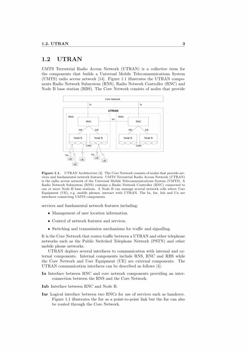
UMTS Terrestrial Radio Access Network (UTRAN) is a collective term forthe components that builds a Universal Mobile Telecommunications System(UMTS) radio access network [14]. Figure 1.1 illustrates the UTRAN compo-nents Radio Network Subsystem (RNS), Radio Network Controller (RNC) andNode B base station (RBS). The Core Network consists of nodes that provide
Node B Node B
RNC
IubIub
Cells
RNS
Node B Node B
RNC
IubIub
Cells
RNSIur
UTRAN
Core Network
UE
UE
UEUE
UE
IuIu
Uu Uu
Figure 1.1. UTRAN Architecture [4]. The Core Network consists of nodes that provide ser-vices and fundamental network features. UMTS Terrestrial Radio Access Network (UTRAN)is the radio access network of the Universal Mobile Telecommunications System (UMTS). ARadio Network Subsystem (RNS) contains a Radio Network Controller (RNC) connected toone or more Node B base stations. A Node B can manage several network cells where UserEquipment (UE), e.g. mobile phones, interact with UTRAN. The Iu, Iur, Iub and Uu areinterfaces connecting UMTS components.
services and fundamental network features including:
• Management of user location information.
• Control of network features and services.
• Switching and transmission mechanisms for traffic and signalling.
It is the Core Network that routes traffic between a UTRAN and other telephonenetworks such as the Public Switched Telephone Network (PSTN) and othermobile phone networks.
UTRAN deploys several interfaces to communication with internal and ex-ternal components. Internal components include RNS, RNC and RBS whilethe Core Network and User Equipment (UE) are external components. TheUTRAN communication interfaces can be described as follows [4]:
Iu Interface between RNC and core network components providing an inter-connection between the RNS and the Core Network.
Iub Interface between RNC and Node B.
Iur Logical interface between two RNCs for use of services such as handover.Figure 1.1 illustrates the Iur as a point-to-point link but the Iur can alsobe routed through the Core Network.
4 Chapter 1. Introduction
Uu Radio interface between UTRAN and User Equipment (UE) where Wide-band Code Division Multiple Access (WCDMA) [14] is deployed.
Ordinary UMTS uses Frequency Division Duplexing (FDD) together withWCDMA radio interface technology. In FDD the uplink and downlink trans-mit on different frequencies. There is another technique called Time DivisionDuplexing (TDD) which allows the uplink and downlink to use the same fre-quency spectrum. Mobile phone operators use regular UMTS, i.e. FDD, forphone services while TDD is targeted at Internet services competing with otherstandards such as e.g. WiMAX [14].
UMTS-FDD is not directly compatible with UMTS-TDD although theyshare many specifications. This report only describes the technology relevantto FDD.
1.2.1 Node Synchronisation
Precision timing is vital in a UMTS Terrestrial Radio Access Network (UTRAN)[4] and both RNC and RBS require a clock source with a precision of at least0.05ppm9 for wide area base station deployment [2]. Although UTRAN nodeshave high quality internal clocks an external reference is required to maintainthe necessary precision. A common technique is to use the network synchroni-sation [17] features included in the physical layer of the Iub to provide a clocksynchronisation reference. However, although the clock reference can be sharedbetween different UTRAN nodes this is not a requirement. For example, anRNC and an RBS within the same RNS are allowed to use independent clockreferences as long as they provide the required precision. Since different clockreferences are allowed the frame counters of UTRAN nodes are not required tobe phase aligned [3].
Data communication between RNC and UE through an RBS uses frametransport. A frame corresponds to a certain amount of time, usually 10ms. Inthe downlink scenario it is the RNC which decides when a frame should leavethe radio interface in the RBS and thus be transmitted to the UE, i.e. theframe receiver needs a reference to determine when to forward the frame. Thisis addressed by the use of frame counters in RNC and RBS. The RNC FrameNumber (RFN) is used by the RNC and the Node B Frame Number (BFN) isused by the RBS. Think of a frame counter as a clock which ticks one step every10ms, e.g. in a time interval of 30ms it is possible to send three frames.
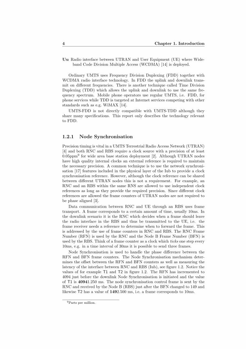
Node Synchronisation is used to handle the phase difference between theRFN and BFN frame counters. The Node Synchronisation mechanism deter-mines the offset between the RFN and BFN counters as well as measuring thelatency of the interface between RNC and RBS (Iub), see figure 1.2. Notice thevalues of for example T1 and T2 in figure 1.2. The RFN has incremented to4094 just before the downlink Node Synchronisation is initiated and the valueof T1 is 40941.250 ms. The node synchronisation control frame is sent by theRNC and received by the Node B (RBS) just after the BFN changed to 149 andlikewise T2 has a value of 1492.500 ms, i.e. a frame corresponds to 10ms.
9Parts per million.
1.2. UTRAN 5
���
������
��
�� � � �� ��� �
� �� � �� �� � �
���������������� ����
��� �� ��������������������� ����
��� �� ��������� �������������������
�
�� ��
������������������� ��!�� ��"�#$%����#����&�������'(���&$��)�*�+����)"
�
Figure 1.2. RNC–Node B Node Synchronisation [3]
1.2.2 Transport Channel Synchronisation
Transport Channel Synchronisation is the concept of synchronising frame trans-port between RNC and RBS. This section describes the transport channel syn-chronisation mechanism valid for all downlink transport channels, such as theForward Access Channel (FACH), Dedicated Channels (DCHs), etc.
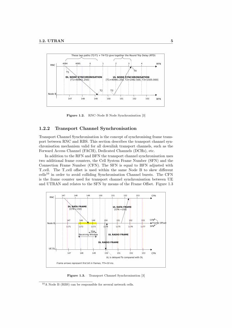
In addition to the RFN and BFN the transport channel synchronisation usestwo additional frame counters, the Cell System Frame Number (SFN) and theConnection Frame Number (CFN). The SFN is equal to BFN adjusted withT cell. The T cell offset is used within the same Node B to skew differentcells10 in order to avoid colliding Synchronisation Channel bursts. The CFNis the frame counter used for transport channel synchronisation between UEand UTRAN and relates to the SFN by means of the Frame Offset. Figure 1.3
���
������
���� � � ���� �� ��
�� �� �� �� ��� �
������������
��������
����������������
��
!"�#$
���� �� � � ���� ��
������������
������������
������������
��������
�� �� � � ���� ��
%�
��
&'(���))*�+
�������������������� ����������� ���������������
!$��*���,'-��������(.'&�����+/�#$
Figure 1.3. Transport Channel Synchronisation [3]
10A Node B (RBS) can be responsible for several network cells.
6 Chapter 1. Introduction
illustrates the scenario of a downlink data frame sent from RNC through RBSto UE with subsequent response [3].
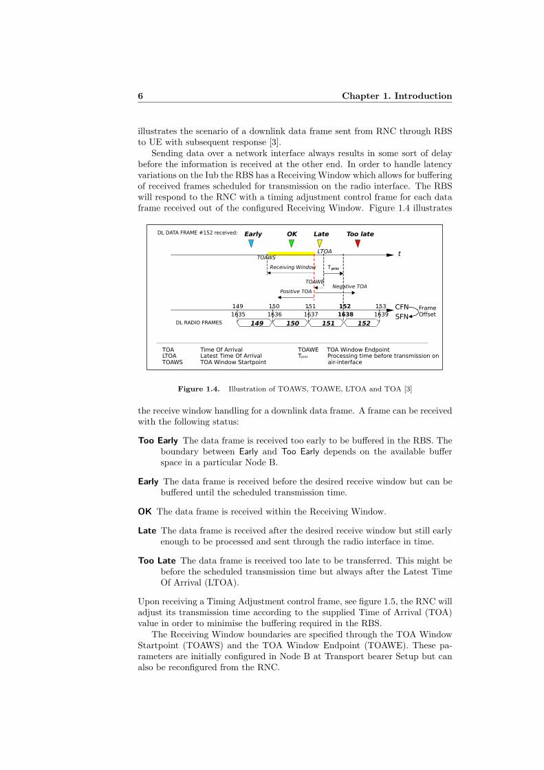
Sending data over a network interface always results in some sort of delaybefore the information is received at the other end. In order to handle latencyvariations on the Iub the RBS has a Receiving Window which allows for bufferingof received frames scheduled for transmission on the radio interface. The RBSwill respond to the RNC with a timing adjustment control frame for each dataframe received out of the configured Receiving Window. Figure 1.4 illustrates
�����
������������������� ��� ���
���
�
������������ ������������� � �������
����
����
������ �����
�����
�����
����� ��������� ���
��� ������������������� ��������������������������� �������� !������" ����
����� �������� !����" ����"� � #� ������$������%�� ������������� �� �
���&���������
'(
�(
�)* ��+ ��� ��� ��,
�-,� �-,- �-,. �� �-,*����������
Figure 1.4. Illustration of TOAWS, TOAWE, LTOA and TOA [3]
the receive window handling for a downlink data frame. A frame can be receivedwith the following status:
Too Early The data frame is received too early to be buffered in the RBS. Theboundary between Early and Too Early depends on the available bufferspace in a particular Node B.
Early The data frame is received before the desired receive window but can bebuffered until the scheduled transmission time.
OK The data frame is received within the Receiving Window.
Late The data frame is received after the desired receive window but still earlyenough to be processed and sent through the radio interface in time.
Too Late The data frame is received too late to be transferred. This might bebefore the scheduled transmission time but always after the Latest TimeOf Arrival (LTOA).
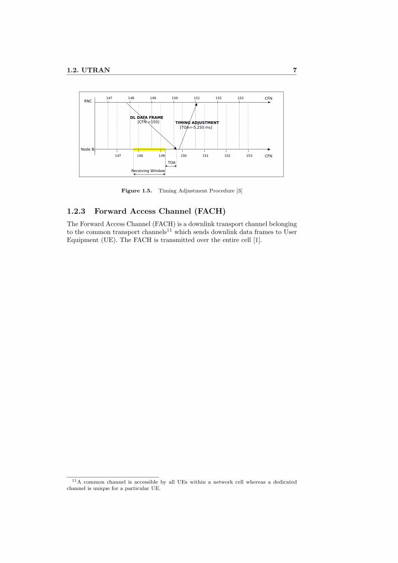
Upon receiving a Timing Adjustment control frame, see figure 1.5, the RNC willadjust its transmission time according to the supplied Time of Arrival (TOA)value in order to minimise the buffering required in the RBS.
The Receiving Window boundaries are specified through the TOA WindowStartpoint (TOAWS) and the TOA Window Endpoint (TOAWE). These pa-rameters are initially configured in Node B at Transport bearer Setup but canalso be reconfigured from the RNC.
1.2. UTRAN 7
���
������
��
���� � � ���� �� ��
�� �� � � ���� ��
�������������������� ������� ������
�������� ������
������� !�"� ��#
���
Figure 1.5. Timing Adjustment Procedure [3]
1.2.3 Forward Access Channel (FACH)
The Forward Access Channel (FACH) is a downlink transport channel belongingto the common transport channels11 which sends downlink data frames to UserEquipment (UE). The FACH is transmitted over the entire cell [1].
11A common channel is accessible by all UEs within a network cell whereas a dedicatedchannel is unique for a particular UE.

8 Chapter 1. Introduction
Chapter 2
Method
The master thesis projects started by building an ATM tunneling software forthe available hardware platform. This process is described in section 2.3. Whena working tunnel implementation had been achieved a methodology for evalu-ating the tunnel behaviour at different network characteristics was developed.The test methodology is described in section 2.1. The setup of the equipmentused to perform the actual testing is described in section 2.2.
2.1 Test method
The basic tests were to see if a network cell could be setup with one or moretransmission channels using the tunnel for ATM transport. This was done usingboth a real RNC [16] and an RNC simulator. Both setups proved successful butwere limited to using a LAN between the tunnel endpoints.
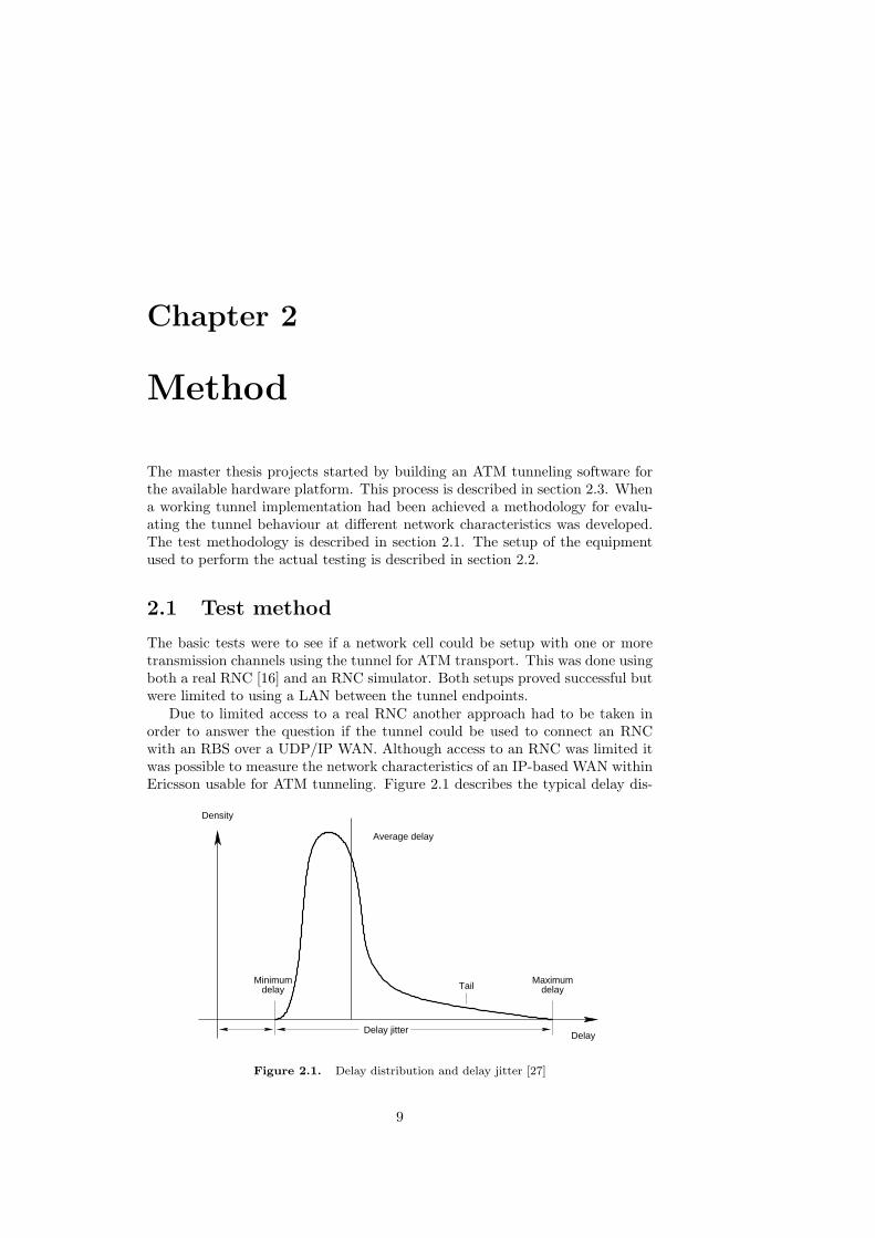
Due to limited access to a real RNC another approach had to be taken inorder to answer the question if the tunnel could be used to connect an RNCwith an RBS over a UDP/IP WAN. Although access to an RNC was limited itwas possible to measure the network characteristics of an IP-based WAN withinEricsson usable for ATM tunneling. Figure 2.1 describes the typical delay dis-
Minimumdelay
Maximumdelay
Delay jitter
Tail
Delay
Average delay
Density
Figure 2.1. Delay distribution and delay jitter [27]
9
10 Chapter 2. Method
tribution and delay jitter of a packet switching network. By measuring thesequantities within the existing WAN the results could be used to create a simu-lated delay scenario where the tunnel performance could be tested. The softwareplatform and the techniques used to simulate the desired network characteristicsare described in section 2.1.1.
A test network with configurable delay distribution and delay jitter makesit possible to see how the ATM tunnel would operate in a real WAN setup.However, it would also be interesting to measure how the RBS responds to thelatency imposed by the tunnel. This would make it possible to give a moredetailed answer to the question if the tunnel could be used for linking RNC andRBS using a UDP/IP WAN. Section 2.1.2 describes a method to accomplishsuch a measurement.
2.1.1 Software platform
Debian GNU/Linux [10] was chosen as the software platform. In this casethe particular GNU/Linux distribution is not significant as long as it provideslibatm [5] and an Network Time Protocol (NTP) client.
A custom 2.6 kernel1 was compiled for the tunnel endpoint machines in orderto enable three important options:
• ATM networking and the ATM driver provided by PROSUM [21].
• Quality of Service and Network Emulation, NetEm [13].
• 1000Hz kernel timer for higher NetEm precision.
The tunnel machines synchronise their clocks with a Symmetricom2 NTP-server, stratum 1, using a NTP client with an update rate of 1 Hz yielding aperceived precision of 0.1ms or lower. The round trip time and latency in eachdirection for UDP packets traversing the network could then be monitored usinga UDPping3 software developed specifically for the thesis project.
The Linux kernel includes sophisticated traffic control facilities with ad-vanced Quality of Service (QoS), Differentiated Services (DiffServ) and filteringcapabilities [15]. NetEm provides network emulation capabilities and can simu-late constant delay, delay jitter, packet loss, packet re-ordering etc.
For example to enable an egress delay of 10ms with 3ms delay jitter a simplecommand such as the following is the only thing required:
tc qdisc add dev eth0 root netem delay 10ms 3ms
2.1.2 Time of Arrival
The Transport Channel Synchronisation, see section 1.2.2, mechanism used forall downlink transport channels will send a Timing Adjustment control frameto the data frame sender, i.e. the RNC, only if the data frame was receivedoutside the Receiving Window. Hence if the Iub has an acceptable latency a
1Linux kernel 2.6.16.29 to be exact.2http://www.symmetricom.com/3UDPping extends the ICMP ping/pong [25] scheme and includes a timestamp in its ping
and pong packets enabling measurement of the network latency in each direction. However,this approach requires the two nodes’ clocks to be synchronised.
2.2. Test setup 11
real RNC would adjust its frame transmission time so that the data frames arereceived within the RBS receiving window and no timing adjustment controlframe would be sent after a stable transmission timing has been found.
The use of an RNC simulator which is not configured to adjust its downlinkdata frame transmission timing creates an interesting situation. In this case eachdownlink data frame will cause a Timing Adjustment control frame to be sentin return since the data frame will always arrive Early. If the maximum latencyon the Iub stays within the time window of Early arrival a Timing Adjustmentcontrol frame will be sent in return to each transmitted downlink data frame.
The Timing Adjustment control frame contains a Time of Arrival (ToA) valuetogether with the indication of whether the data frame was Early, OK, Late orToo Late. As illustrated in figure 1.4 the ToA value uses the TOA WindowEndpoint (TOAWE) as reference with a negative value if the data frame waslate and positive value if the frame arrived within the window or was early. Theearlier a data frame arrives the higher ToA value.
By observing the ToA returned in the Timing Adjustment control frame re-turned for every data frame sent using the RNC simulator the Iub characteristicscan be measured using the RBS.
2.2 Test setup
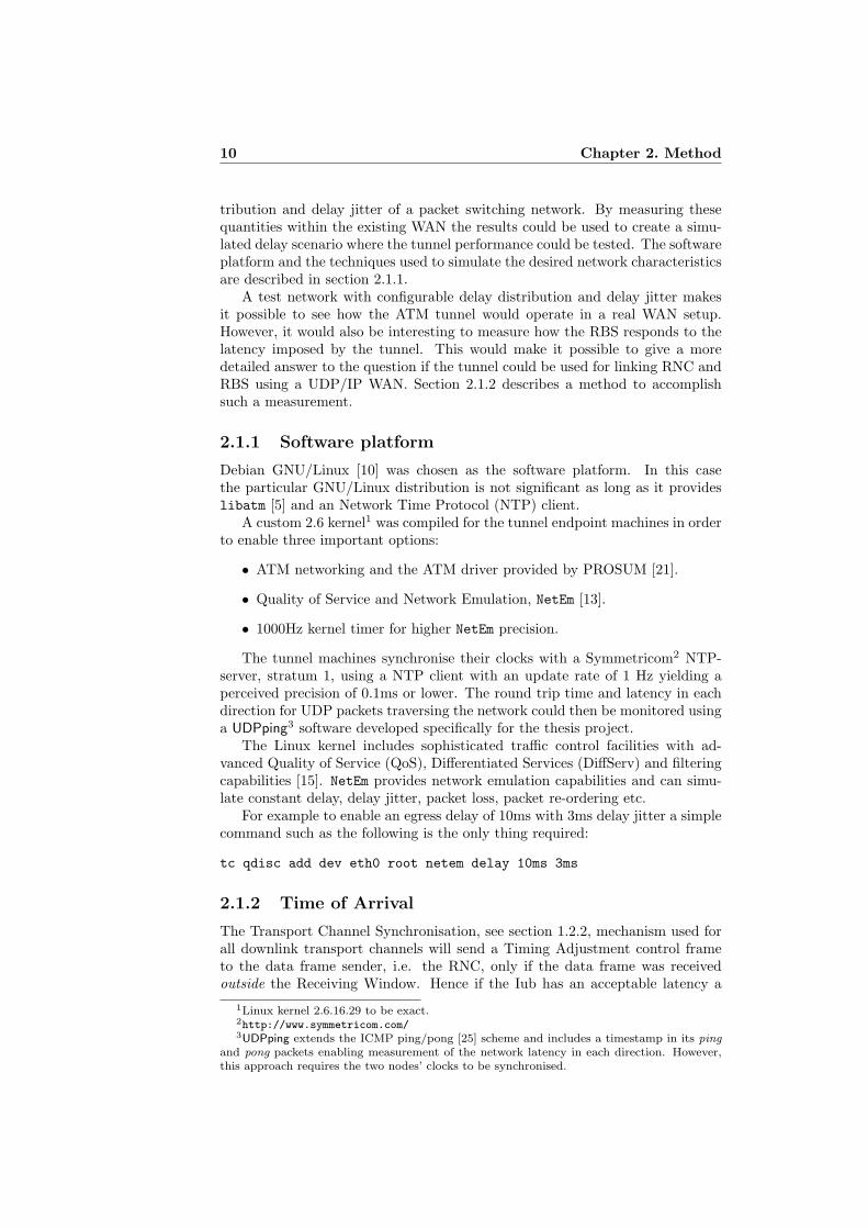
The equipment used to verify the effects on the Iub using an ATM tunnel issetup as illustrated in figure 2.2. ATM traffic on the Iub between RNC andRBS is transparently forwarded through an ATM tunnel setup consisting oftwo tunnel endpoint nodes communicating over a Local or Wide Area Network(LAN or WAN).
netem
UDP/IP
Ethernet
netem
UDP/IP
Ethernet
RNC
or
RNCsim
NodeB
(RBS)
ETM4 ETM4
LAN/WAN
ATMtunnel
ATM
OC3/STM−1
ATMtunnel
ATM
OC3/STM−1
Iub Iub
Figure 2.2. A Radio Network Controller (RNC), real or simulator, connects to a NodeB base station (RBS) using the RNC–RBS interface (Iub). Two identical ATMtunnel nodesinterface with RNC/RBS using the operating system’s Asynchronous Transfer Mode (ATM)stack with an optical carrier 3, OC3/STM-1, 155.52 Mbit/s fiber optic interface. The ATM-tunnel nodes communicate using the UDP/IP protocol over a Local or Wide Area Network(LAN or WAN). Artificial delay jitter can be introduced between the nodes using the networkemulation tool NetEm
12 Chapter 2. Method
2.3 Implementation
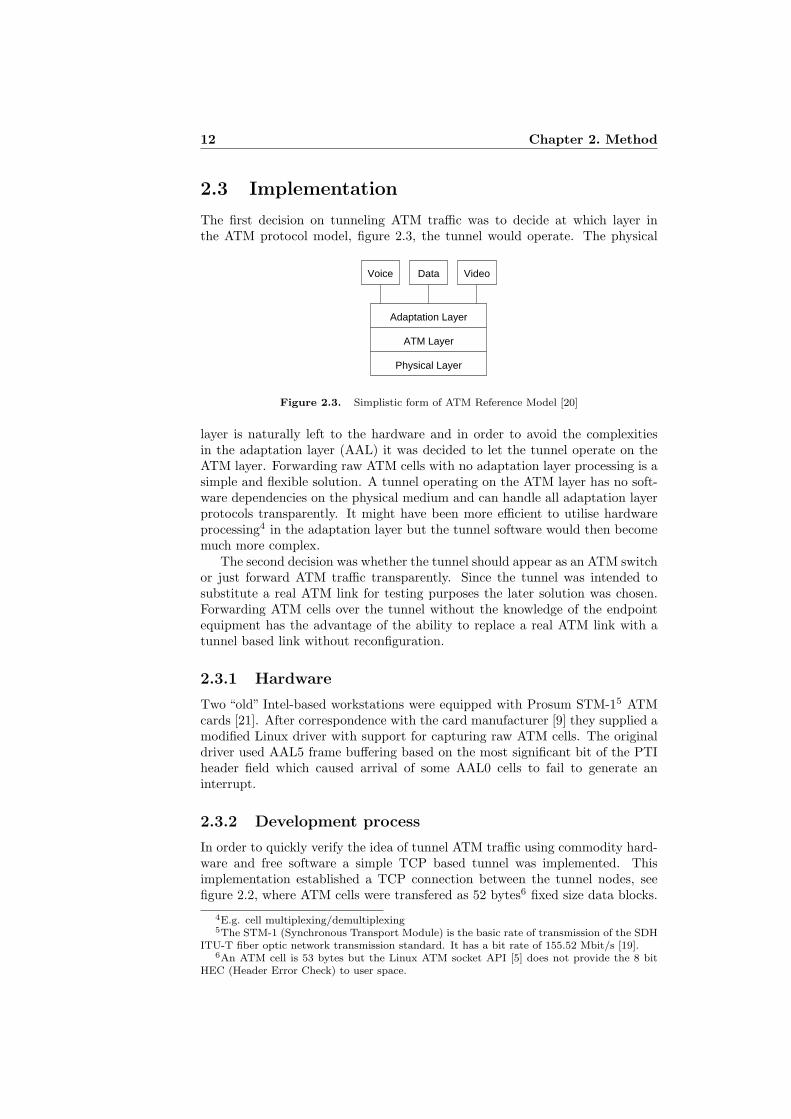
The first decision on tunneling ATM traffic was to decide at which layer inthe ATM protocol model, figure 2.3, the tunnel would operate. The physical
Voice Data Video
Physical Layer
Adaptation Layer
ATM Layer
Figure 2.3. Simplistic form of ATM Reference Model [20]
layer is naturally left to the hardware and in order to avoid the complexitiesin the adaptation layer (AAL) it was decided to let the tunnel operate on theATM layer. Forwarding raw ATM cells with no adaptation layer processing is asimple and flexible solution. A tunnel operating on the ATM layer has no soft-ware dependencies on the physical medium and can handle all adaptation layerprotocols transparently. It might have been more efficient to utilise hardwareprocessing4 in the adaptation layer but the tunnel software would then becomemuch more complex.
The second decision was whether the tunnel should appear as an ATM switchor just forward ATM traffic transparently. Since the tunnel was intended tosubstitute a real ATM link for testing purposes the later solution was chosen.Forwarding ATM cells over the tunnel without the knowledge of the endpointequipment has the advantage of the ability to replace a real ATM link with atunnel based link without reconfiguration.
2.3.1 Hardware
Two “old” Intel-based workstations were equipped with Prosum STM-15 ATMcards [21]. After correspondence with the card manufacturer [9] they supplied amodified Linux driver with support for capturing raw ATM cells. The originaldriver used AAL5 frame buffering based on the most significant bit of the PTIheader field which caused arrival of some AAL0 cells to fail to generate aninterrupt.
2.3.2 Development process
In order to quickly verify the idea of tunnel ATM traffic using commodity hard-ware and free software a simple TCP based tunnel was implemented. Thisimplementation established a TCP connection between the tunnel nodes, seefigure 2.2, where ATM cells were transfered as 52 bytes6 fixed size data blocks.
4E.g. cell multiplexing/demultiplexing5The STM-1 (Synchronous Transport Module) is the basic rate of transmission of the SDH
ITU-T fiber optic network transmission standard. It has a bit rate of 155.52 Mbit/s [19].6An ATM cell is 53 bytes but the Linux ATM socket API [5] does not provide the 8 bit
HEC (Header Error Check) to user space.
2.3. Implementation 13
The TCP based tunnel worked well enough in a LAN environment for a realRNC to successfully establish voice and packet data channels through an RBS toa set of UEs represented by mobile phones from different vendors. As expectedthe TCP approach suffered from latency problems and did not work satisfactorywhen artificial network delay was introduced.
The TCP based tunnel was reworked to use a simple UDP based solution.Each 52 byte cell was sent unmodified in a single UDP packet. The latencyproblems seen in the TCP implementation was much improved and likewise thetolerance for artificial network delay. However since the UDP implementationwas based on the assumption that packet reordering is unlikely in a LAN envi-ronment it had no tolerance for delay jitter. A fundamental difference betweenATM and IP is that ATM guarantees cell order while IP does not. It is okayfor the ATM layer to drop a cell but it must not deliver cells out of order.
The good results from the “proof of concept” implementations motivatedthe development of a more sophisticated ATM tunnel software. The followingrequirements were placed on the final tunnel design:
• The tunnel must not reorder ATM cells even if the transport protocolreorders packets.
• The tunnel must be able to properly handle delay jitter.
• The jitter handling must have a timeout function which discards cells thathave not arrived within a specified receive window.
• The tunnel must be able to transfer several ATM cells within a single IPpacket.
• The tunnel should impose as little delay as possible when transferring anATM cell.
These requirements are easily motivated. The ATM layer guarantees cellorder and operating on the ATM layer so must the tunnel. An Internet con-nection almost always has some sort of delay jitter, it might be small for highquality links but it is still there and so must be addressed by the tunnel. Jitterhandling, i.e. the process of replaying received data in the order it was sent,will impose some kind of delay. If for example cells A, B, C, D was sent andC, D, A was received the receiver can immediately send cell A but must waitfor cell B before it can send C and D. This waiting period must be configurableor else it could result in unpredictable latency being imposed by the tunnel.IP does generally not have optimal performance when the packet size is small.Therefore in order to address both low latency and high throughput the tunnelmust be able to detect bursts of ATM traffic and send several cells within thesame IP packet.
2.3.3 Tunnel protocol
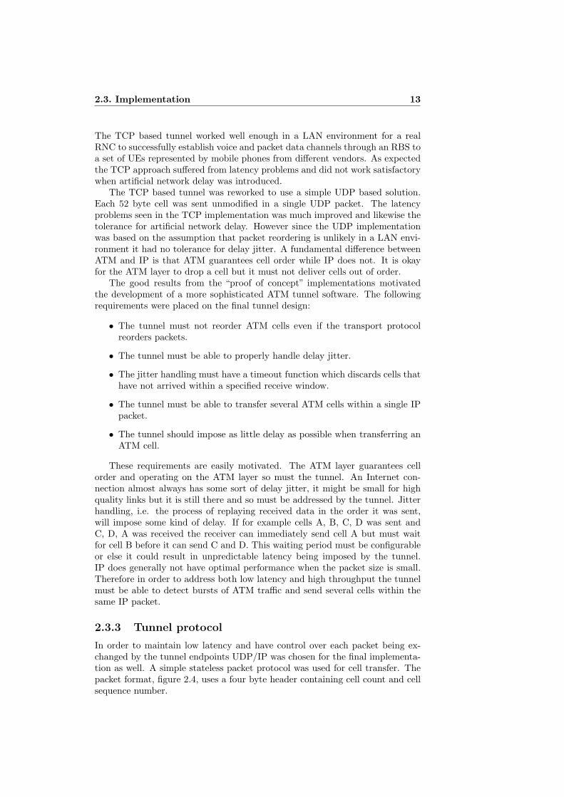
In order to maintain low latency and have control over each packet being ex-changed by the tunnel endpoints UDP/IP was chosen for the final implementa-tion as well. A simple stateless packet protocol was used for cell transfer. Thepacket format, figure 2.4, uses a four byte header containing cell count and cellsequence number.
14 Chapter 2. Method
IP header20 bytes
UDP header8 bytes
ATM cells52 bytes each
Sequence number3 bytes1 byte
Cell count
310
Figure 2.4. ATM tunnel protocol packet format
Cell count 8-bit integer reflecting the number of 52-byte ATM cells sent inthe packet. The maximum of 255 cells gives a maximum IP packet size of20 + 8 + 4 + 255 · 52 = 13292 bytes.
Sequence number 24-bit sequence number of the first cell in the packet. Thesequence number reflects to ATM cells, not tunnel packets. The sequencenumber wraps around after approximately 16.7 million cells which corre-sponds to 224·48
10242 = 768 megabytes of ATM cell payload7.
The packet header was designed to add as little overhead as possible while stillproviding robust sequence number handling even for high bandwidth scenarios.The overhead for single cell transfer 28+4
28+4+52 = 38.1% is rather high due to the28 bytes UDP/IP header.
The maximum packet size should be selected according to the MTU of thetunnel link. Although the packet format supports large packets the resultingIP fragmentation might cause latency issues which cannot be controlled by thetunnel software. A typical LAN environment with an MTU of 1500 bytes cantransfer 28 cells, 20+8+4+28 ·52 = 1488 bytes packet, without fragmentationgiving an overhead of 28+4
1488 = 2.2%. An Internet scenario using the minimumMTU for IP networks [25] of 576 bytes can transfer 10 cells giving a packet sizeof 552 bytes and an overhead of 5.8%.
2.3.4 Algorithm
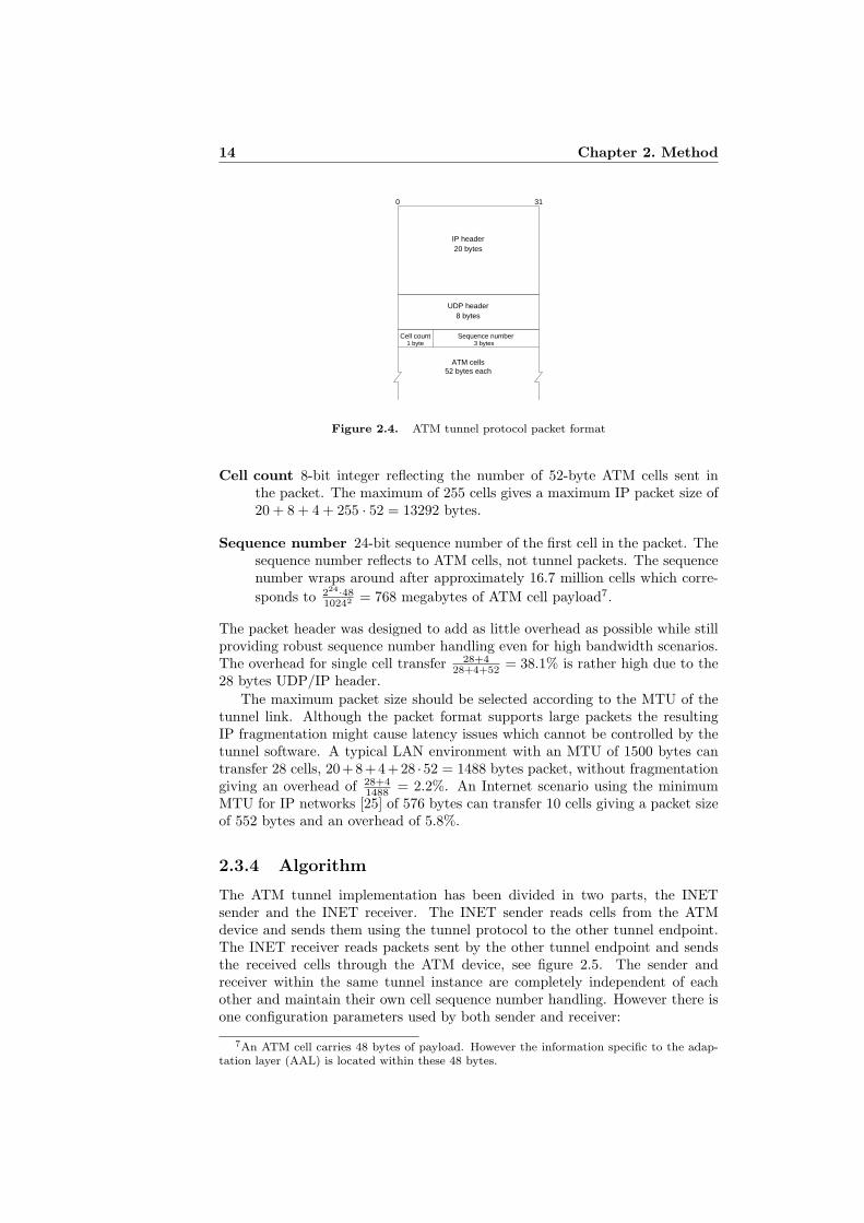
The ATM tunnel implementation has been divided in two parts, the INETsender and the INET receiver. The INET sender reads cells from the ATMdevice and sends them using the tunnel protocol to the other tunnel endpoint.The INET receiver reads packets sent by the other tunnel endpoint and sendsthe received cells through the ATM device, see figure 2.5. The sender andreceiver within the same tunnel instance are completely independent of eachother and maintain their own cell sequence number handling. However there isone configuration parameters used by both sender and receiver:
7An ATM cell carries 48 bytes of payload. However the information specific to the adap-tation layer (AAL) is located within these 48 bytes.
2.3. Implementation 15
� �� �� �� �� �� �� �� �� �� �� �� �� �� �� �� �� �� �� �� �
� �� �� �� �� �� �� �� �� �� �� �� �� �� �� �� �� �� �� �� �
ATM cells
ATM cells
INET receiver
INET sender
INET sender
INET receiver ATM cells
ATM cells
ATM link ATM link
IP network
A
ATM tunnel instance ATM tunnel instance
B
Figure 2.5. ATM tunnel overview
packet size the maximum number of cells allowed to be sent or received in asingle UDP packet. The packet size parameter should be set so that IPfragmentation is avoided. This parameter must have the same value inboth tunnel instances.
INET sender
Configuration parameter:
send buffer delay the maximum time waiting for cells to fill the packet bufferbefore transmission.
The INET sender uses a single cell buffer for incoming cells. It does only buffercells for one packet at a time. Packet transmission is initiated when the bufferis full, i.e. the packet size limit has been reached, or the timeout imposed bythe send buffer delay has expired. The algorithm of the INET sender can bedescribed as follows:
1. Set seqnext = 0.
2. Set cellindex = 0.
3. Set timeout = timecurrent + send buffer delay.
4. While timecurrent < timeout and cellindex < packet size
(a) Read 52-bytes ATM cell8 (the call must respect the timeout).
(b) Store cell in packet buffer at position 4 + cellindex ∗ 52.
(c) Set cellindex = cellindex + 1.
5. Write packet header using cell count cellindex and sequence number seqnext
to the first 4 bytes of the packet buffer.
6. Send the packet buffer contents to the remote tunnel endpoint.
7. Set seqnext = seqnext + cellindex.
8. Goto 2.
8ATM cell with HEC removed as presented by the Linux ATM socket API [5].
16 Chapter 2. Method
INET receiver
Configuration parameters:
replay window size the maximum number of cells handled by the replay win-dow (jitter buffer).
replay window delay the maximum time waiting for missing cells to arrive.
replay window reset timeout the maximum time received cells are allowedto have a sequence number outside the replay window, thus being dis-carded, before the window is reset.
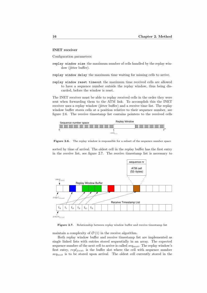
The INET receiver must be able to replay received cells in the order they weresent when forwarding them to the ATM link. To accomplish this the INETreceiver uses a replay window (jitter buffer) and a receive time list. The replaywindow buffer stores cells at a position relative to their sequence number, seefigure 2.6. The receive timestamp list contains pointers to the received cells
� � � � � � � � � � � � � � � � � � � � � � � � � � � � � � � � � � � � � � � � � � � � � � � � � � � � � � � � � � � � � � � �� � � � � � � � � � � � � � � � � � � � � � � � � � � � � � � � � � � � � � � � � � � � � � � � � � � � � � � � � � � � � � � �
� � � � � � � � � � � � � � � � � � � � � � � � � � � � � � � � � � � � � � � � � � � � � � � � � � � � � � � � � � � � � � � �� � � � � � � � � � � � � � � � � � � � � � � � � � � � � � � � � � � � � � � � � � � � � � � � � � � � � � � � � � � � � � � �
seqnext
224
Sequence number space Replay Window
0
Figure 2.6. The replay window is responsible for a subset of the sequence number space
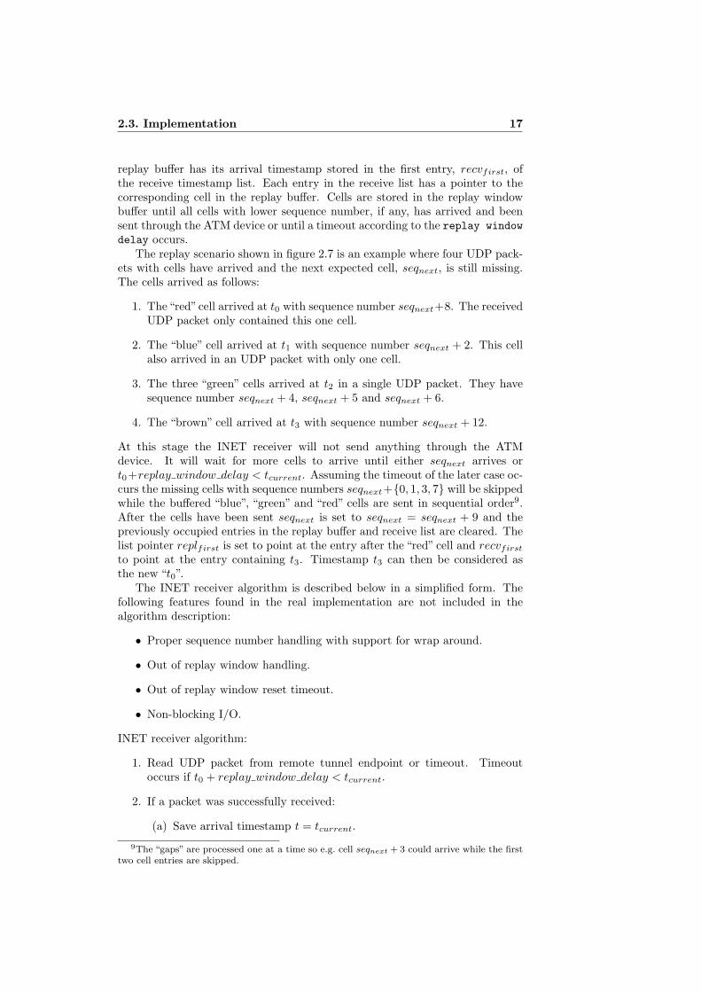
sorted by time of arrival. The oldest cell in the replay buffer has the first entryin the receive list, see figure 2.7. The receive timestamp list is necessary to
t 0 t 2 t 2 t 2
sequence nr
ATM cell(52−bytes)
t 1
seqnext
recv
repl
first
first
Receive Timestamp List
Replay Window Buffer
t 3
Figure 2.7. Relationship between replay window buffer and receive timestamp list
maintain a complexity of O (1) in the receive algorithm.Both replay window buffer and receive timestamp list are implemented as
single linked lists with entries stored sequentially in an array. The expectedsequence number of the next cell to arrive is called seqnext. The replay window’sfirst entry, replfirst, is the buffer slot where the cell with sequence numberseqnext is to be stored upon arrival. The oldest cell currently stored in the
2.3. Implementation 17
replay buffer has its arrival timestamp stored in the first entry, recvfirst, ofthe receive timestamp list. Each entry in the receive list has a pointer to thecorresponding cell in the replay buffer. Cells are stored in the replay windowbuffer until all cells with lower sequence number, if any, has arrived and beensent through the ATM device or until a timeout according to the replay windowdelay occurs.
The replay scenario shown in figure 2.7 is an example where four UDP pack-ets with cells have arrived and the next expected cell, seqnext, is still missing.The cells arrived as follows:
1. The“red”cell arrived at t0 with sequence number seqnext+8. The receivedUDP packet only contained this one cell.
2. The “blue” cell arrived at t1 with sequence number seqnext + 2. This cellalso arrived in an UDP packet with only one cell.
3. The three “green” cells arrived at t2 in a single UDP packet. They havesequence number seqnext + 4, seqnext + 5 and seqnext + 6.
4. The “brown” cell arrived at t3 with sequence number seqnext + 12.
At this stage the INET receiver will not send anything through the ATMdevice. It will wait for more cells to arrive until either seqnext arrives ort0+replay window delay < tcurrent. Assuming the timeout of the later case oc-curs the missing cells with sequence numbers seqnext+{0, 1, 3, 7} will be skippedwhile the buffered “blue”, “green” and “red” cells are sent in sequential order9.After the cells have been sent seqnext is set to seqnext = seqnext + 9 and thepreviously occupied entries in the replay buffer and receive list are cleared. Thelist pointer replfirst is set to point at the entry after the “red” cell and recvfirst
to point at the entry containing t3. Timestamp t3 can then be considered asthe new “t0”.
The INET receiver algorithm is described below in a simplified form. Thefollowing features found in the real implementation are not included in thealgorithm description:
• Proper sequence number handling with support for wrap around.
• Out of replay window handling.
• Out of replay window reset timeout.
• Non-blocking I/O.
INET receiver algorithm:
1. Read UDP packet from remote tunnel endpoint or timeout. Timeoutoccurs if t0 + replay window delay < tcurrent.
2. If a packet was successfully received:
(a) Save arrival timestamp t = tcurrent.
9The “gaps” are processed one at a time so e.g. cell seqnext + 3 could arrive while the firsttwo cell entries are skipped.
18 Chapter 2. Method
(b) Extract sequence number, seq, and cellcount from the packet header,see section 2.3.3.
(c) Find the replay window entry corresponding to seq by offsettingreplfirst with seq − seqnext
10. This is an O (1) operation since thereplay window buffer is implemented as a single linked list stored asan array.
(d) Copy the cellcount ATM cells from the packet to the replay windowbuffer.
(e) Add cellcount entries into the end of the receive timestamp list usingtimestamp t with pointers to the corresponding entries in the replaywindow buffer.
3. If the replay window buffer is non-empty:
(a) If the replay buffer entry at replfirst is empty, goto 4.
(b) Send the cell at replfirst through the ATM device.
(c) Clear the replay buffer entry at replfirst and the corresponding re-ceive timestamp list entry.
(d) Update replfirst to point to the next replay buffer entry.
(e) Increment seqnext by one.
(f) Goto 3a.
4. If t0 + replay window delay < tcurrent:
(a) If replfirst refers to a non-empty replay buffer entry, goto 5.
(b) Update replfirst to point to the next replay buffer entry.
(c) Increment seqnext by one.
(d) Goto 4a.
5. Goto 1.
10This is a simplification since the real implementation correctly handles sequence numberwrap around.
Chapter 3
QoS in IP networks
The network technology to use when Quality of Service (QoS) is a requirementhas long been thought to be ATM. The transport mechanism in ATM built onthe switching of small cells was motivated by the low latency requirements intelecommunication networks. Today modern fiber optic networks provide suchspeeds that the queueing delay of even full length 1500 byte packets incur nosignificant delay. Furthermore there are scalability issues of the extra ATM layerstarting to become apparent at speeds increasing above 1 Gbit/s and the cost ofmaintaining both high speed IP and ATM networks can be significant [20] [28].
The Internet datagram model used by IP networks provide no resource guar-antees and does not distinguish between different types of services. This is asevere limitation that is starting to become more apparent as the demand ofnew services with specific network requirements increase in popularity [27].
The need for QoS in IP networks and the increasing cost of maintaining highspeed ATM networks have motivated the development of several new technolo-gies. Differentiated Services (DiffServ), see section 3.1, provides a mechanismfor scalable QoS capabilities in IP networks. Multiprotocol Label Switching(MPLS), see section 3.2, introduces a new approach to packet forwarding whichcan incorporate the demands of both Internet users and ATM deployers withinthe world of telecommunications.
The Connectivity Packet Platform (CPP) developed by Ericsson is a carrier-class technology that has been positioned for access and transport products inmobile and fixed networks. CPP is deployed within Ericsson’s UTRAN equip-ment and has support for IP technologies such as DiffServ and MPLS to providecost effective alternatives to ATM for service providers [28].
3.1 Differentiated Services
The Differentiated Services (DiffServ) networking architecture was published bythe IETF in 1998 [8] and specifies a relatively simple, scalable and course-grainedmechanism providing QoS capabilities for Internet traffic. DiffServ enables re-source allocation by use of packet classification, traffic policing and class-basedforwarding. Rather than trying to guarantee network resources for individualend-to-end flows DiffServ divides traffic into a fixed number of forwarding classesfor which resources are allocated. Resource allocation in DiffServ is thus per-
19
20 Chapter 3. QoS in IP networks
formed for aggregated traffic and although different service levels and resourceassurance can be provided absolute amounts of bandwidth or fixed delay boundscannot be guaranteed for individual flows [27].
Interior node
Interior node
Interior node
Boundary nodeBoundary node
Boundary nodeBoundary node
ISP network
Customer network
Customer network
Customer network
Customer network
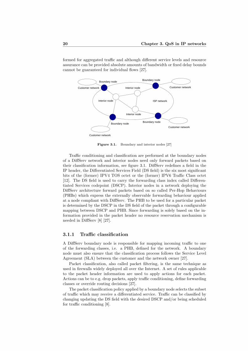
Figure 3.1. Boundary and interior nodes [27]
Traffic conditioning and classification are performed at the boundary nodesof a DiffServ network and interior nodes need only forward packets based ontheir classification information, see figure 3.1. DiffServ redefines a field in theIP header, the Differentiated Services Field (DS field) is the six most significantbits of the (former) IPV4 TOS octet or the (former) IPV6 Traffic Class octet[12]. The DS field is used to carry the forwarding class index called Differen-tiated Services codepoint (DSCP). Interior nodes in a network deploying theDiffServ architecture forward packets based on so called Per-Hop Behaviours(PHBs) which express the externally observable forwarding behaviour appliedat a node compliant with DiffServ. The PHB to be used for a particular packetis determined by the DSCP in the DS field of the packet through a configurablemapping between DSCP and PHB. Since forwarding is solely based on the in-formation provided in the packet header no resource reservation mechanism isneeded in DiffServ [8] [27].
3.1.1 Traffic classification
A DiffServ boundary node is responsible for mapping incoming traffic to oneof the forwarding classes, i.e. a PHB, defined for the network. A boundarynode must also ensure that the classification process follows the Service LevelAgreement (SLA) between the customer and the network owner [27].
Packet classification, also called packet filtering, is the same technique asused in firewalls widely deployed all over the Internet. A set of rules applicableto the packet header information are used to apply actions for each packet.Actions can be to e.g. drop packets, apply traffic conditioning, define forwardingclasses or override routing decisions [27].
The packet classification policy applied by a boundary node selects the subsetof traffic which may receive a differentiated service. Traffic can be classified bychanging updating the DS field with the desired DSCP and/or being scheduledfor traffic conditioning [8].
3.2. Multiprotocol Label Switching 21
3.1.2 Traffic conditioning
Traffic conditioning is the process of policing traffic according to the TrafficConditioning Agreement (TCA). The TCA consists of the traffic conditioningrules specified in the SLA together with the rules implicit from the relevantservice requirements and/or from a DiffServ network’s service provisioning pol-icy. Traffic conditioning is performed at the DiffServ boundary nodes and aconditioner can contain four elements: meter, marker, shaper and dropper [8][27].
Interior nodes may be able to perform limited traffic conditioning functionssuch as DSCP re-marking [8].
3.2 Multiprotocol Label Switching
The Multiprotocol Label Switching (MPLS) architecture [22] was organised bythe IETF to introduce label switching within IP networks and to allow forseamless IP/ATM integration. Although IP was the initial focus when theIETF started the standardisation process of MPLS it is motivated by a severalfactors [20] [27]:
• MPLS greatly simplifies IP forwarding making it much more efficient andeasy to implement in hardware.
• MPLS allows IP to be transferred over existing ATM networks in a lesscumbersome way than e.g. Classical IP over ATM.
• ATM can be transferred over MPLS networks while maintaining guaran-teed Quality of Service (QoS).
• MPLS provides explicit routing whereby a node can explicitly specify thedestination path rather than having to make a hop-by-hop decision at eachnode.
• MPLS makes Traffic Engineering easier, i.e. the process of using the dif-ferent links in a network optimally.
Routing in a classical IP network is performed on a “per-hop” basis whereeach router decides the next-hop based on the destination address in the IPpacket header. The IP routing algorithm uses the longest-prefix match approachwhich is inefficient and expensive to implement in hardware [20].
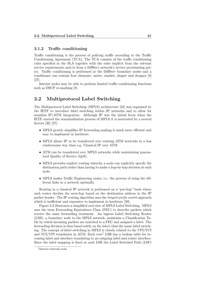
Figure 3.2 illustrates a simplified overview of MPLS Label Switching. MPLSuses the term Forwarding Equivalence Class (FEC) to describe packets whichreceive the same forwarding treatment. An ingress Label Switching Router(LSR), a boundary node to the MPLS network, maintains a Classification Ta-ble by which incoming packets are matched to a FEC and assigned a label. Theforwarding decision is then based solely on the label, thus the name label switch-ing. The concept of label switching in MPLS is closely related to the VPI/VCIand VCI/VPI translation in ATM. Each core1 LSR has a lookup table for in-coming label and interface translating to an outgoing label and router interface.Since the label mapping is fixed at each LSR the Label Switched Path (LSP)
1Interior network node.
22 Chapter 3. QoS in IP networks
Figure 3.2. MPLS Label Switching [20]
a packet will traverse can be determined from the label assigned at the ingressLSR [20] [27].
An MPLS network need to be configured to populate the label lookup tablesat each participating LSR. This process is performed by a Label DistributionProtocol (LDP) of which there exist two standardised protocols, CR-LDP andRSVP-TE [27]. However in February 2003 the MPLS working group decidedto focus future efforts only on RSVP-TE and undertake no further work onCR-LDP [6].
Chapter 4
Results
A working software solution for tunneling ATM traffic over an UDP/IP networkhas been developed and implemented, see section 4.1. The tunneling softwarehas been tested with an RNC simulator and a Node B base station using in-dependent timing measurements collected from the Node B. The results arepresented in section 4.3.
4.1 ATMtunnel software
The ATMtunnel software developed in this master thesis project implements thespecification described in section 2.3 as a POSIX1 -compliant application writtenin C. The application has been thoroughly tested and verified and uses a singlethreaded select()-based approach for high predictability and easy debugging.The whole reception and transmission path within the application includingbuffer handling are O (1) with regard to the processing of an ATM cell.
The ATMtunnel application provides the following key features:
• ATM traffic is forwarded on the transport layer (AAL0) which providessupport for all ATM Adaptation Layers.
• ATM forwarding is performed transparently making ATM reconfigurationunnecessary.
• ATM cells are forwarded through the tunnel as fast as possible.
• Delay jitter causing re-ordering in the UDP transport will activate the cellreplay functionality to guarantee cell order.
• The maximum delay introduced by the cell replay handling is configurable.
• A properly received cell will not be delayed longer than the specified max-imum delay.
• Cells arriving “too late” will be discarded as is allowed in the ATM trans-port layer while cell order is maintained.
1Portable Operating System Interface.
23
24 Chapter 4. Results
• Sequence number out-of-sync scenarios caused e.g. by network outage isaddressed by the configurable reset timeout.
• ATM traffic is forwarded based on PVC. One tunnel instance per PVCenables different tunnel settings for different ATM transports.
• Configurable buffer fill delay for increased efficiency of UDP/IP networkutilisation.
• The ATMtunnel can be configured to display statistics of forwarded cells,packets, cell loss, etc.
The ATMtunnel software has configurable behaviour and is invoked as follows:
ATMtunnel by Ralf Nyren (C) 2006-2007
Usage: atmtunnel [-dvh] [options] [itf.]vpi.vci host portOptions:-p max number of cells in UDP packet-w max send delay waiting for cells to fill UDP packet-r replay window size (cells)-D replay window delay waiting for missing cells-T replay window out-of-sync reset timeout-L localaddr[:localport]-c cell/packet counter print timeout
4.2 Reference delay distribution
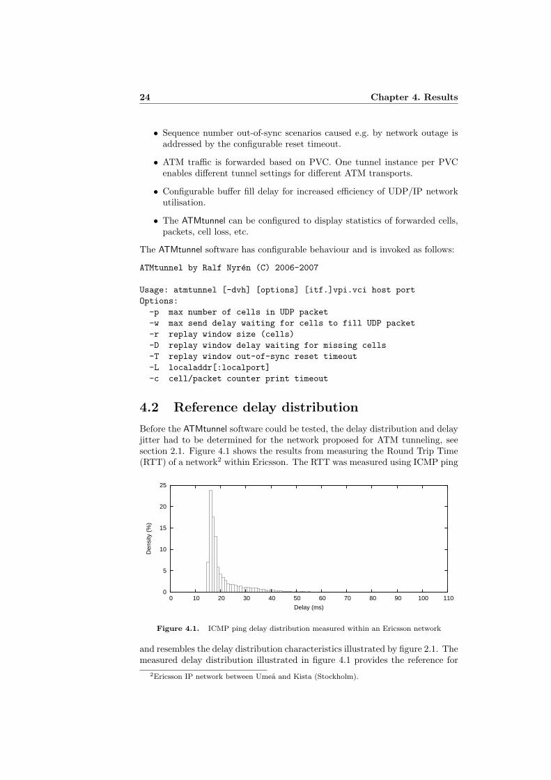
Before the ATMtunnel software could be tested, the delay distribution and delayjitter had to be determined for the network proposed for ATM tunneling, seesection 2.1. Figure 4.1 shows the results from measuring the Round Trip Time(RTT) of a network2 within Ericsson. The RTT was measured using ICMP ping
0
5
10
15
20
25
0 10 20 30 40 50 60 70 80 90 100 110
Den
sity
(%
)
Delay (ms)
Figure 4.1. ICMP ping delay distribution measured within an Ericsson network
and resembles the delay distribution characteristics illustrated by figure 2.1. Themeasured delay distribution illustrated in figure 4.1 provides the reference for
2Ericsson IP network between Umea and Kista (Stockholm).
4.3. Test results 25
the artificial delay used to simulate the effects of using the ATMtunnel softwarein a WAN. The mean value of the delay distribution was 20.5ms.
4.3 Test results
The tests were performed using an RNC simulator connected via two ATMtunneling endpoint machines to a Node B base station as described in section 2.2.
The effects of the ATM tunnel on the Iub were measured using the Time ofArrival ToA value of the Timing Adjustment control frame sent by the RBS asdescribed in section 2.1.2. The ToA values correspond to the downlink transportframes sent from RNC simulator to RBS over the Iub.
The delay distribution of the real network described in section 4.2 was sim-ulated using Linux NetEm with a constant delay parameter of 10ms and ±3msdelay jitter. This corresponds to an approximate round trip delay of at least20± 6ms.
4.3.1 FACH transport
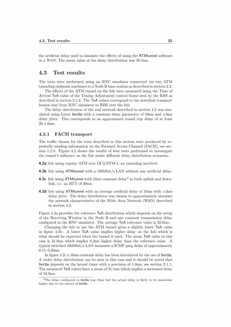
The traffic chosen for the tests described in this section were produced by re-peatedly sending information on the Forward Access Channel (FACH), see sec-tion 1.2.3. Figure 4.2 shows the results of four tests performed to investigatethe tunnel’s influence on the Iub under different delay distribution scenarios:
4.2a Iub using regular ATM over OC3/STM-1, no tunneling involved.
4.2b Iub using ATMtunnel with a 100Mbit/s LAN without any artificial delay.
4.2c Iub using ATMtunnel with 10ms constant delay3 in both uplink and down-link, i.e. an RTT of 20ms.
4.2d Iub using ATMtunnel with an average artificial delay of 10ms with ±3msdelay jitter. The delay distribution was chosen to approximately simulatethe network characteristics of the Wide Area Network (WAN) describedin section 4.2.
Figure 4.2a provides the reference ToA distribution which depends on the setupof the Receiving Window in the Node B and any constant transmission delayconfigured in the RNC simulator. The average ToA reference value is 32.0ms.
Changing the Iub to use the ATM tunnel gives a slightly lower ToA valuein figure 4.2b. A lower ToA value implies higher delay on the Iub which iswhat should be expected when the tunnel is used. The mean ToA value in thiscase is 31.8ms which implies 0.2ms higher delay than the reference value. Atypical switched 100Mbit/s LAN measures a ICMP ping delay of approximately0.15–0.20ms.
In figure 4.2c a 10ms constant delay has been introduced by the use of NetEm.A wider delay distribution can be seen in this case and it should be noted thatNetEm depends on the kernel timer with a precision of 1.0ms, see section 2.1.1.The measured ToA values have a mean of 21.1ms which implies a increased delayof 10.9ms.
3The delay configured in NetEm was 10ms but the actual delay is likely to be somewhathigher due to the nature of NetEm.
26 Chapter 4. Results
0
10
20
30
40
50
60
12 14 16 18 20 22 24 26 28 30 32 34
Den
sity
(%
)
Time of Arrival (ms)
(a)
0
10
20
30
40
50
60
12 14 16 18 20 22 24 26 28 30 32 34
Den
sity
(%
)
Time of Arrival (ms)
(b)
0
10
20
30
40
50
60
12 14 16 18 20 22 24 26 28 30 32 34
Den
sity
(%
)
Time of Arrival (ms)
(c)
0
10
20
30
40
50
60
12 14 16 18 20 22 24 26 28 30 32 34
Den
sity
(%
)
Time of Arrival (ms)
(d)
Figure 4.2. Time of Arrival (ToA) of downlink FACH frames measured by Node B. Fig-ure 4.2a shows the reference downlink ToA distribution of the Iub using regular ATM transport,i.e. no tunneling involved. The delay imposed by the ATMtunnel and IP network is the differ-ence between the reference ToA distribution in figure 4.2a and the results in figure 4.2b, 4.2cand 4.2d. Figure 4.2b illustrates the delay imposed on the Iub by using the ATMtunnel in aLAN environment. Figure 4.2c shows the effects of the ATMtunnel when an artificial constantdelay of 10ms was added to the IP network using Linux NetEm. In figure 4.2d a WAN wassimulated using an average artificial delay of 10ms with ±3ms delay jitter
A 10ms delay and ±3ms jitter were used when measuring the Time of Arrivalshown in figure 4.2d. The mean value is 20.0ms which corresponds to a 12.0msaverage delay. The 2.0ms delay difference as compared to the NetEm settingis likely to be explained by the replay window handling in the ATMtunnel andthe precision problems in NetEm. The ToA value varies from 8.4ms to 24.5msalthough the majority represents a delay jitter of approximately 6ms distributedbetween 17.8ms and 23.8ms.
All FACH frames sent by the RNC simulator during the described tests weresuccessfully transmitted on the radio interface by the RBS.
4.3. Test results 27
4.3.2 Dedicated channel packet data transport
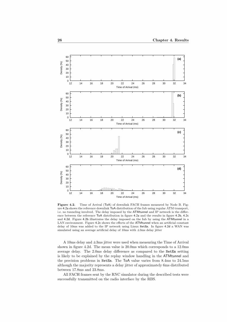
Using the ATMtunnel software over an IP network is likely to require some addi-tional transport security. The test presented in this section uses an ATM tunnelsetup as described in section 2.2 with the addition of a Virtual Private Network(VPN) installed between the ATM tunnel endpoints. The VPN software usedwas OpenVPN4 which is capable of forwarding the ATM tunnel IP traffic usingUDP/IP.
The test illustrated in figure 4.3 used packet data traffic at a speed of384kbit/s on a dedicated channel, i.e. a transport channel dedicated to a par-ticular User Equipment (UE). During the test an artificial delay distributionwith an average of 10ms and ±3ms delay jitter was used. The delay was createdusing Linux NetEm with the same settings as in section 4.3.1, figure 4.2d.
0
1
2
3
4
5
0 5 10 15 20 25 30
Den
sity
(%
)
Time of Arrival (ms)
Figure 4.3. Time of Arrival (ToA) of downlink data frames sent on a dedicated transportchannel at 384kbit/s. The ATM traffic on the Iub was tunneled over a Virtual Private Network(VPN) using the ATMtunnel software. The IP network used by the VPN was setup with anaverage artificial delay of 10ms with ±3ms delay jitter
The Time of Arrival distribution shown in figure 4.3 has a mean value of19.8ms implying an average delay of 12.2ms, using figure 4.2a as reference.Compared to the results presented in figure 4.2d an additional average delay of0.2ms can be seen when the VPN was used.
4http://openvpn.net/

28 Chapter 4. Results
Chapter 5
Concluding remarks
This master thesis project proves the concept of tunneling ATM traffic over anIP network for the latency sensitive communication between RNC and RBS inUTRAN.
Comparison of Iub latency between pure ATM based transport and tunneledtransport shows an additional delay of approximately 0.2ms in a LAN environ-ment. Typical packet delay in a 100Mbit/s LAN environment is 0.1–0.2msincluding IP stack processing implying the developed ATMtunnel software tocause insignificant delay.
Simulation of a real LAN/WAN situation using the Free Software Linuxkernel IP stack NetEm functionality show predictable results. Based on inves-tigation of an Ericsson WAN, potentially usable for ATM tunneled IP basedremote connection of RNC and RBS, it can be concluded that the ATMtunnelsoftware could indeed be used to connect physically remote test equipment fortest and verification purposes.
The ATMtunnel software combined with tools such as NetEm have proved tobe a very useful and cost effective system for test and verification of transmissionrelated issues.
5.1 Limitations
The ATM tunnel setup described in this report does not relay the networksynchronisation mechanisms [17] provided by the physical media of the ATMtransport, i.e. the fiber optic OC3/STM-1 link. An RBS connected to an RNCusing the ATMtunnel software can therefore not rely on the Iub to provide aclock reference signal. However, an external clock source can be provided to anRBS by use of for example an atomic reference clock or a GPS receiver. AnRBS test environment is likely to have plenty of reliable clock sources.
5.2 Future work
The impact of the ATMtunnel on the Iub communication could be further inves-tigated for various network characteristics. For example a more realistic delaydistribution function could be implemented for use with NetEm. A Wide AreaNetwork (WAN) test with a real RNC would certainly also be interesting.
29
30 Chapter 5. Concluding remarks
The tests described in this report only used a fraction of the available Iubbandwidth. The performance of the ATMtunnel software during higher band-width scenarios could be investigated using traffic models producing extensiveATM load.
There exist other solutions for tunneling ATM traffic over an IP networkwhich would be interesting to compare to the current approach used in thismaster thesis project. An example is the Layer 2 Tunneling Protocol Version 3(L2TPv3) which includes an ATM cell relay mode [23] similar to the techniquesused in the ATMtunnel software. However, at the time of writing the authorcould not find a freely available implementation of L2TPv3 with support forATM over L2TPv3.
Chapter 6
Acknowledgements
The author would like to thank Per Hurtig and Caroline Muzikants at Ericssonfor access to and test support in a real UMTS Radio Access Network. Theauthor would also like to thank Marie Dahlberg and Mikael Larsson, RBSIoV,TietoEnator for supporting this master thesis project.
31
32 Chapter 6. Acknowledgements
References
[1] 3GPP. Technical Specification Group Radio Access Network; Physicalchannels and mapping of transport channels onto physical channels (FDD)(Release 6). 3rd Generation Partnership Project, Dec. 2005. 3GPP TS25.211 V6.7.0.
[2] 3GPP. Technical Specification Group Radio Access Network; Base Station(BS) radio transmission and reception (FDD) (Release 6). 3rd GenerationPartnership Project, Dec. 2006. 3GPP TS 25.104 V6.14.0.
[3] 3GPP. Technical Specification Group Radio Access Network; Synchronisa-tion in UTRAN Stage 2 (Release 6). 3rd Generation Partnership Project,Dec. 2006. 3GPP TS 25.402 V6.5.0.
[4] 3GPP. Technical Specification Group Radio Access Network; UTRANoverall description (Release 6). 3rd Generation Partnership Project, Dec.2006. 3GPP TS 25.401 V6.9.0.
[5] Almesberger, W. Linux ATM API Draft, version 0.4, 19 July 1995.
[6] Andersson, L., and Swallow, G. The Multiprotocol Label Switching(MPLS) Working Group decision on MPLS signaling protocols. RFC 3468(Informational), Feb. 2003.
[7] ATM Forum. Inverse Multiplexing for ATM (IMA), Specification 1.1,Mar. 1999. ATM Forum AF-PHY-0086.001.
[8] Blake, S., Black, D., Carlson, M., Davies, E., Wang, Z., andWeiss, W. An Architecture for Differentiated Service. RFC 2475 (Infor-mational), Dec. 1998. Updated by RFC 3260.
[9] Bucari, C. Private Communication. PROSUM Networking Products,June 2006.
[10] Debian. Debian GNU/Linux – The Universial Operating System. Webpage, 19 Nov. 2007. http://www.debian.org/.
[11] Free Software Foundation. The Free Software Definition. Web page,1 Nov. 2007. http://www.fsf.org/licensing/essays/free-sw.html.
[12] Grossman, D. New Terminology and Clarifications for Diffserv. RFC3260 (Informational), Apr. 2002.
33
34 REFERENCES
[13] Hemminger, S. Network Emulation with NetEm. linux.conf.au (Apr.2005). http://developer.osdl.org/shemminger/netem/LCA2005_pap-er.pdf.
[14] Holma, H., and Toskala, A. WCDMA for UMTS: Radio Access forThird Generation Mobile Communications, revised ed. John Wiley & Sons,Ltd., Chichester, West Sussex, England, 2001.
[15] Hubert, B., Graf, T., Maxwell, G., van Mook, R., van Oost-erhout, M., Schroeder, P. B., Spaans, J., and Larroy, P.Linux Advanced Routing and Traffic Control HOWTO, 29 Oct. 2003.http://lartc.org/lartc.pdf.
[16] Hurtig, P. Private Communication. Ericsson, RBSIoV, Oct. 2006.
[17] ITU-T. Synchronization layer functions. International Telecommunica-tions Union, Geneva, Switzerland, July 1999. ITU-T RecommendationG.781.
[18] ITU-T. Physical/electrical characteristics of hierarchical digital interfaces.International Telecommunications Union, Geneva, Switzerland, 29 Nov.2001. ITU-T Recommendation G.703.
[19] ITU-T. Network node interface for the synchronous digital hierarchy(SDH). International Telecommunications Union, Geneva, Switzerland,14 Dec. 2003. ITU-T Recommendation G.707/Y.1322.
[20] Kasera, S. ATM Networks: Concepts and Protocols. McGraw-Hill Com-munications, New York, NY, USA, 2006.
[21] PROSUM Networking Products. ATM Network Interface Cards forFiber Optic and UTP 155 Mbps Connections. Web page, 14 Nov. 2007.http://www.prosum.net/atm155_E.html.
[22] Rosen, E., Viswanathan, A., and Callon, R. Multiprotocol LabelSwitching Architecture. RFC 3031 (Proposed Standard), Jan. 2001.
[23] Singh, S., Townsley, M., and Pignataro, C. Asynchronous TransferMode (ATM) over Layer 2 Tunneling Protocol Version 3 (L2TPv3). RFC4454 (Proposed Standard), May 2006.
[24] Skold, J., Lundevall, M., Parkvall, S., and Sundelin, M. Broad-band data performance of third-generation mobile systems. Ericsson Re-view, 1 (2005).
[25] Stevens, W. R. TCP/IP Illustrated, Volume 1. Addison Wesley Long-man, Inc., 1994.
[26] Vainshtein, A., and Stein, Y. Structure-Agnostic Time Division Mul-tiplexing (TDM) over Packet (SAToP). RFC 4553 (Proposed Standard),June 2006.
[27] Wang, Z. Internet QoS: Architectures and Mechanisms for Quality ofService. Morgan Kaufmann Publishers Inc., San Francisco, CA, USA, 2001.
REFERENCES 35
[28] Orjan Kling, L., Ake Lindholm, Marklund, L., and Nilsson,G. B. CPP – Cello packet platform. Ericsson Review, 2 (2002).

36 REFERENCES