𝑃6𝑚𝑚 vandaele et al. - rsc
TRANSCRIPT

Vandaele et al.
Electronic Supplementary Information
Continuous-feed nanocasting process for the synthesis of bismuth nanowire composites
1 Materials
Pluronics P123 (EO20PO70EO20, Mw = 5800), 98% reagent grade tetraethylorthosilicate (TEOS), 65w%
nitric acid, 36w% hydrochloric acid, 98.5 % xylenes and 99% n-butanol were purchased from Sigma
Aldrich. 99.999% bismuth(III) oxide and 98% hydrazine monohydrate were supplied by Alfa Aesar. 99%
toluene and 98% methanol were supplied by Fiers, while 97% n-octane was purchased from TCI Europe
N.V. All reagents were used as received.
2 Characterization
X-Ray powder Diffraction (XRD) patterns were recorded on a Thermo Scientific ARL X’TRA X-Ray
Diffractometer with the Bragg–Brentano theta-2 theta configuration and using Cu Ka radiation. Topas
Academic V4.1 software was used for Rietveld refinement1. Nitrogen sorption experiments were
performed at 77 K with a Micromeritics TriStar 3000 device. Samples were vacuum dried at 120 °C for
12 h prior to analysis. The surface area was calculated using the BET method while the pore-size
distribution was determined by analysis of the adsorption branch of the isotherms using the BJH
method. Thermogravimetric analysis (TGA) was performed on a NETZSCH STA 449-F3 Jupiter device and
TEM images were taken with a JEOL JSM-207 7600F device. X-ray fluorescence (XRF) measurements
were performed on a Rigaku NEXCG device under helium atmosphere and RX5 target.
3 SBA-15 and KIT-6 mesoporous silica templates
SBA-15 was synthesized by dissolving 4 g P123 in 120 mL 2 mol/L HCl solution and 30 mL distilled
water at RT. Next, the solution was heated to 45 °C and 9.1 mL TEOS was added while vigorously stirring
for 5 h. Subsequently, the mixture was aged at 90 °C for 18 h under static conditions. Finally, the
precipitate was collected via filtration, dried overnight at RT, and calcinated at 550 °C for 6 h in air with
a heating rate of 2 °C/min.2
KIT-6 was synthesized by dissolving 4 g P123 in 150 mL 0.5 mol/L HCl solution and 4.9 mL butanol at
RT. Next the solution was heated to 35 °C and 9.2 mL TEOS was added while vigorous stirring. The
mixture was stirred at that temperature for 24 h and subsequently aged at 90 °C for 24 h under static
conditions. Finally, the precipitate was collected via filtration, dried overnight at RT and calcinated at
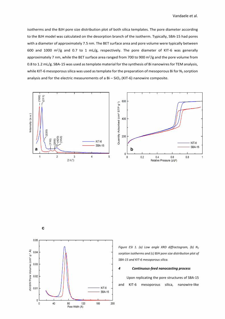
550 °C for 6 h in air with a heating rate of 2 °C/min.3 Low angle X-ray powder diffraction data (XRPD) of
SBA-15 and KIT-6 are shown in Figure ESI 1a, indicating that the synthesized KIT-6 mesoporous silica
possesses a cubic, interconnected pore system with the -space group symmetry, while SBA-15 𝐼𝑎 ̅3𝑑
shows a hexagonal ordered pore system. Figure ESI 1b and c show respectively the N2 sorption 𝑃6𝑚𝑚
Electronic Supplementary Material (ESI) for ChemComm.This journal is © The Royal Society of Chemistry 2017
Vandaele et al.
isotherms and the BJH pore size distribution plot of both silica templates. The pore diameter according
to the BJH model was calculated on the desorption branch of the isotherm. Typically, SBA-15 had pores
with a diameter of approximately 7.5 nm. The BET surface area and pore volume were typically between
600 and 1000 m2/g and 0.7 to 1 mL/g, respectively. The pore diameter of KIT-6 was generally
approximately 7 nm, while the BET surface area ranged from 700 to 900 m2/g and the pore volume from
0.8 to 1.2 mL/g. SBA-15 was used as template material for the synthesis of Bi nanowires for TEM analysis,
while KIT-6 mesoporous silica was used as template for the preparation of mesoporous Bi for N2 sorption
analysis and for the electric measurements of a Bi – SiO2 (KIT-6) nanowire composite.
Figure ESI 1. (a) Low angle XRD diffractogram, (b) N2
sorption isotherms and (c) BJH pore size distribution plot of
SBA-15 and KIT-6 mesoporous silica.
4 Continuous-feed nanocasting process
Upon replicating the pore structures of SBA-15
and KIT-6 mesoporous silica, nanowire-like
a b
c
Vandaele et al.
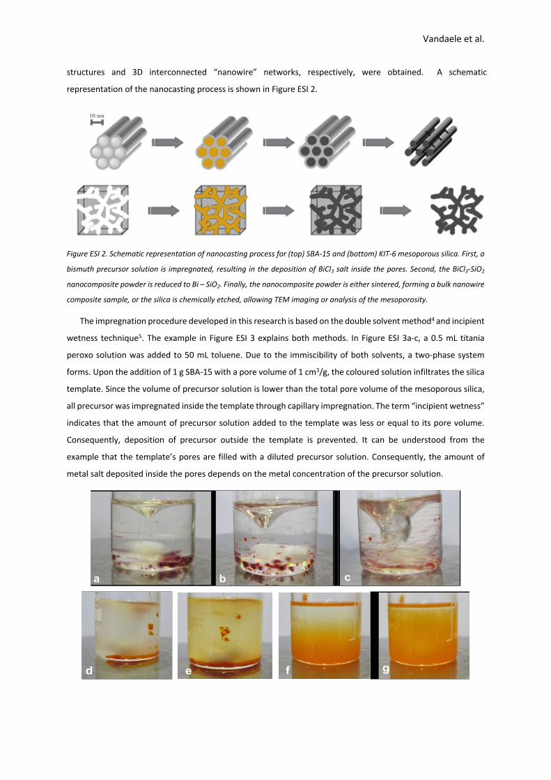
structures and 3D interconnected “nanowire” networks, respectively, were obtained. A schematic
representation of the nanocasting process is shown in Figure ESI 2.
Figure ESI 2. Schematic representation of nanocasting process for (top) SBA-15 and (bottom) KIT-6 mesoporous silica. First, a
bismuth precursor solution is impregnated, resulting in the deposition of BiCl3 salt inside the pores. Second, the BiCl3-SiO2
nanocomposite powder is reduced to Bi – SiO2. Finally, the nanocomposite powder is either sintered, forming a bulk nanowire
composite sample, or the silica is chemically etched, allowing TEM imaging or analysis of the mesoporosity.
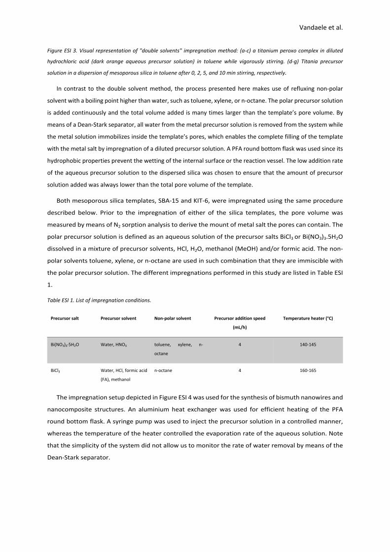
The impregnation procedure developed in this research is based on the double solvent method4 and incipient
wetness technique5. The example in Figure ESI 3 explains both methods. In Figure ESI 3a-c, a 0.5 mL titania
peroxo solution was added to 50 mL toluene. Due to the immiscibility of both solvents, a two-phase system
forms. Upon the addition of 1 g SBA-15 with a pore volume of 1 cm3/g, the coloured solution infiltrates the silica
template. Since the volume of precursor solution is lower than the total pore volume of the mesoporous silica,
all precursor was impregnated inside the template through capillary impregnation. The term “incipient wetness”
indicates that the amount of precursor solution added to the template was less or equal to its pore volume.
Consequently, deposition of precursor outside the template is prevented. It can be understood from the
example that the template’s pores are filled with a diluted precursor solution. Consequently, the amount of
metal salt deposited inside the pores depends on the metal concentration of the precursor solution.
a c
gfed
b
Vandaele et al.
Figure ESI 3. Visual representation of "double solvents" impregnation method: (a-c) a titanium peroxo complex in diluted
hydrochloric acid (dark orange aqueous precursor solution) in toluene while vigorously stirring. (d-g) Titania precursor
solution in a dispersion of mesoporous silica in toluene after 0, 2, 5, and 10 min stirring, respectively.
In contrast to the double solvent method, the process presented here makes use of refluxing non-polar
solvent with a boiling point higher than water, such as toluene, xylene, or n-octane. The polar precursor solution
is added continuously and the total volume added is many times larger than the template’s pore volume. By
means of a Dean-Stark separator, all water from the metal precursor solution is removed from the system while
the metal solution immobilizes inside the template’s pores, which enables the complete filling of the template
with the metal salt by impregnation of a diluted precursor solution. A PFA round bottom flask was used since its
hydrophobic properties prevent the wetting of the internal surface or the reaction vessel. The low addition rate
of the aqueous precursor solution to the dispersed silica was chosen to ensure that the amount of precursor
solution added was always lower than the total pore volume of the template.
Both mesoporous silica templates, SBA-15 and KIT-6, were impregnated using the same procedure
described below. Prior to the impregnation of either of the silica templates, the pore volume was
measured by means of N2 sorption analysis to derive the mount of metal salt the pores can contain. The
polar precursor solution is defined as an aqueous solution of the precursor salts BiCl3 or Bi(NO3)3.5H2O
dissolved in a mixture of precursor solvents, HCl, H2O, methanol (MeOH) and/or formic acid. The non-
polar solvents toluene, xylene, or n-octane are used in such combination that they are immiscible with
the polar precursor solution. The different impregnations performed in this study are listed in Table ESI
1.
Table ESI 1. List of impregnation conditions.
Precursor salt Precursor solvent Non-polar solvent Precursor addition speed
(mL/h)
Temperature heater (°C)
Bi(NO3)3·5H2O Water, HNO3 toluene, xylene, n-
octane
4 140-145
BiCl3 Water, HCl, formic acid
(FA), methanol
n-octane 4 160-165
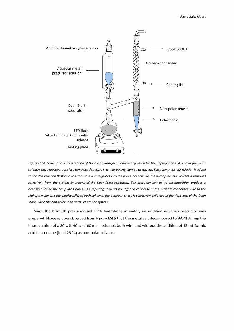
The impregnation setup depicted in Figure ESI 4 was used for the synthesis of bismuth nanowires and
nanocomposite structures. An aluminium heat exchanger was used for efficient heating of the PFA
round bottom flask. A syringe pump was used to inject the precursor solution in a controlled manner,
whereas the temperature of the heater controlled the evaporation rate of the aqueous solution. Note
that the simplicity of the system did not allow us to monitor the rate of water removal by means of the
Dean-Stark separator.
Vandaele et al.
Figure ESI 4. Schematic representation of the continuous-feed nanocasting setup for the impregnation of a polar precursor
solution into a mesoporous silica template dispersed in a high-boiling, non-polar solvent. The polar precursor solution is added
to the PFA reaction flask at a constant rate and migrates into the pores. Meanwhile, the polar precursor solvent is removed
selectively from the system by means of the Dean-Stark separator. The precursor salt or its decomposition product is
deposited inside the template’s pores. The refluxing solvents boil off and condense in the Graham condenser. Due to the
higher density and the immiscibility of both solvents, the aqueous phase is selectively collected in the right arm of the Dean
Stark, while the non-polar solvent returns to the system.
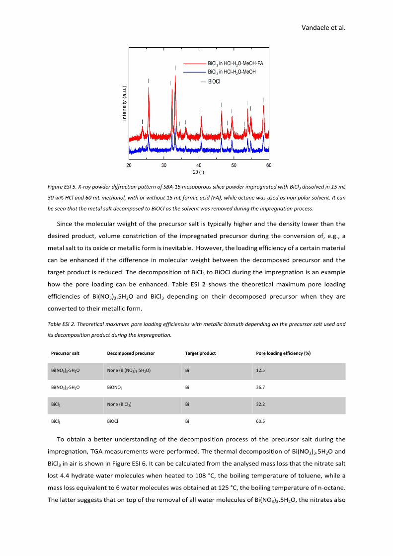
Since the bismuth precursor salt BiCl3 hydrolyses in water, an acidified aqueous precursor was
prepared. However, we observed from Figure ESI 5 that the metal salt decomposed to BiOCl during the
impregnation of a 30 w% HCl and 60 mL methanol, both with and without the addition of 15 mL formic
acid in n-octane (bp. 125 °C) as non-polar solvent.
Cooling IN
Addition funnel or syringe pump Cooling OUT
Dean Stark separator
Polar phase
Non-polar phase
PFA flaskSilica template + non-polar
solvent
Heating plate
Aqueous metal precursor solution
Graham condenser
Vandaele et al.
Figure ESI 5. X-ray powder diffraction pattern of SBA-15 mesoporous silica powder impregnated with BiCl3 dissolved in 15 mL
30 w% HCl and 60 mL methanol, with or without 15 mL formic acid (FA), while octane was used as non-polar solvent. It can
be seen that the metal salt decomposed to BiOCl as the solvent was removed during the impregnation process.
Since the molecular weight of the precursor salt is typically higher and the density lower than the
desired product, volume constriction of the impregnated precursor during the conversion of, e.g., a
metal salt to its oxide or metallic form is inevitable. However, the loading efficiency of a certain material
can be enhanced if the difference in molecular weight between the decomposed precursor and the
target product is reduced. The decomposition of BiCl3 to BiOCl during the impregnation is an example
how the pore loading can be enhanced. Table ESI 2 shows the theoretical maximum pore loading
efficiencies of Bi(NO3)3.5H2O and BiCl3 depending on their decomposed precursor when they are
converted to their metallic form.
Table ESI 2. Theoretical maximum pore loading efficiencies with metallic bismuth depending on the precursor salt used and
its decomposition product during the impregnation.
Precursor salt Decomposed precursor Target product Pore loading efficiency (%)
Bi(NO3)3·5H2O None (Bi(NO3)3.5H2O) Bi 12.5
Bi(NO3)3·5H2O BiONO3 Bi 36.7
BiCl3 None (BiCl3) Bi 32.2
BiCl3 BiOCl Bi 60.5
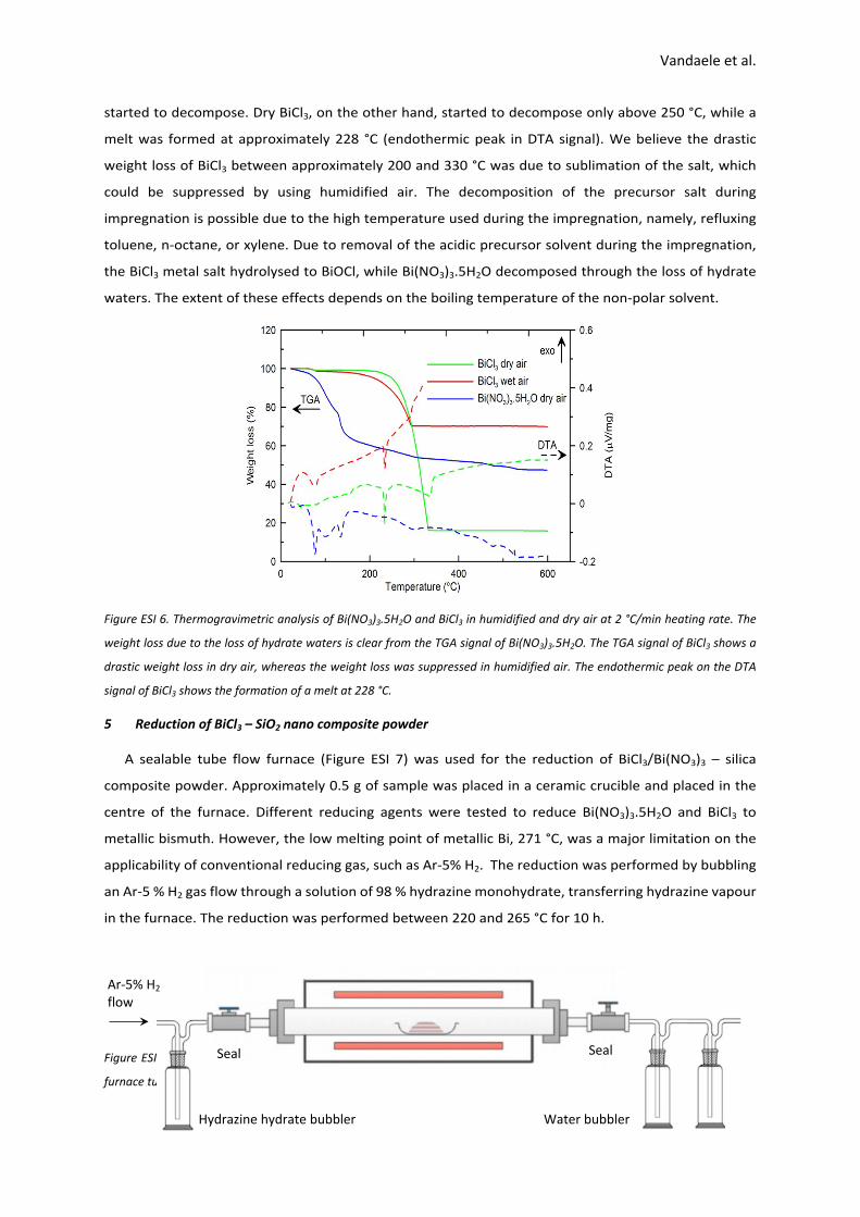
To obtain a better understanding of the decomposition process of the precursor salt during the
impregnation, TGA measurements were performed. The thermal decomposition of Bi(NO3)3.5H2O and
BiCl3 in air is shown in Figure ESI 6. It can be calculated from the analysed mass loss that the nitrate salt
lost 4.4 hydrate water molecules when heated to 108 °C, the boiling temperature of toluene, while a
mass loss equivalent to 6 water molecules was obtained at 125 °C, the boiling temperature of n-octane.
The latter suggests that on top of the removal of all water molecules of Bi(NO3)3.5H2O, the nitrates also
Vandaele et al.
started to decompose. Dry BiCl3, on the other hand, started to decompose only above 250 °C, while a
melt was formed at approximately 228 °C (endothermic peak in DTA signal). We believe the drastic
weight loss of BiCl3 between approximately 200 and 330 °C was due to sublimation of the salt, which
could be suppressed by using humidified air. The decomposition of the precursor salt during
impregnation is possible due to the high temperature used during the impregnation, namely, refluxing
toluene, n-octane, or xylene. Due to removal of the acidic precursor solvent during the impregnation,
the BiCl3 metal salt hydrolysed to BiOCl, while Bi(NO3)3.5H2O decomposed through the loss of hydrate
waters. The extent of these effects depends on the boiling temperature of the non-polar solvent.
Figure ESI 6. Thermogravimetric analysis of Bi(NO3)3.5H2O and BiCl3 in humidified and dry air at 2 °C/min heating rate. The
weight loss due to the loss of hydrate waters is clear from the TGA signal of Bi(NO3)3.5H2O. The TGA signal of BiCl3 shows a
drastic weight loss in dry air, whereas the weight loss was suppressed in humidified air. The endothermic peak on the DTA
signal of BiCl3 shows the formation of a melt at 228 °C.
5 Reduction of BiCl3 – SiO2 nano composite powder
A sealable tube flow furnace (Figure ESI 7) was used for the reduction of BiCl3/Bi(NO3)3 – silica
composite powder. Approximately 0.5 g of sample was placed in a ceramic crucible and placed in the
centre of the furnace. Different reducing agents were tested to reduce Bi(NO3)3.5H2O and BiCl3 to
metallic bismuth. However, the low melting point of metallic Bi, 271 °C, was a major limitation on the
applicability of conventional reducing gas, such as Ar-5% H2. The reduction was performed by bubbling
an Ar-5 % H2 gas flow through a solution of 98 % hydrazine monohydrate, transferring hydrazine vapour
in the furnace. The reduction was performed between 220 and 265 °C for 10 h.
Figure ESI 7. Sealable horizontal flow furnace for the reduction of Bi(NO3)3/BiCl3 – SiO2 nanocomposite powder. The glass
furnace tube can slide out of the furnace and transferred to the glovebox for further manipulation of the powder.
Hydrazine hydrate bubbler
Seal Seal
Water bubbler
Ar-5% H2 flow

Vandaele et al.
Bulk Bi2O3 and BiCl3 powder were used to investigate the influence of different atmospheres on their
reduction to metallic Bi. ZnO was used as internal standard to perform Rietveld refinement and calculate
the fraction of crystalline vs amorphous Bi, as well as the amount of secondary phases. The heat
treatments were conducted in a tubular furnace in a flow of Ar – 5% H2 gas, either pure or bubbled
through a solution of hydrazine monohydrate (N2H4.H2O). A flow rate of 20 mL/min was used and the
samples were reduced for 10 h at 220 °C, 250 °C, and 265 °C. Hydrazine was used here as it is a powerful
and clean reducing agent, since all decomposition products are gaseous.6,7 However, a minimum
concentration of 64 % hydrazine solution is required to obtain sufficient reducing power. Namely, the
reducing capacity reduces quickly as the solution becomes more diluted. X-ray diffraction (XRD) patterns
of BiCl3 reduced at different temperatures in a flow of Ar - 5% H2 and in the presence of N2H4 vapour are
depicted in Figure ESI 8.
Figure ESI 8. X-ray diffraction patterns of BiCl3 reduced at different temperatures in Ar - 5% H2 and in the presence of N2H4
vapour. The diffraction peaks of the internal standard ZnO, which was used to quantify the amount of crystalline Bi and
secondary phase BiOCl.
The Rietveld refining data calculated from the recorded X-ray diffraction pattern is reported in Table
ESI 3. It is shows that a minimum temperature of 250 °C and a reduction time of 10 h is required to
reduce BiCl3 in N2H4 vapour to metallic Bi. In the absence of hydrazine vapour, very little Bi phase was
formed when reduced at 265 °C in Ar-5% H2.
Table ESI 3. Rietveld refinement data of BiCl3 powder reduced at different temperatures and atmospheres for 10 h. The data
shows that the presence of N2H4 vapour was crucial to reduce BiCl3 to metallic Bi. A temperature of 250 °C and a reduction
time of 10 h in N2H4 loaded Ar - 5% H2 was required to reduce BiCl3.
Material Red. Temp. Atmosphere Bi Bi2O3 BiOCl Amorphous
BiCl3 220 °C 5 % H2 + N2H4 32 % 0 % 17 % 51 %
BiCl3 250 °C 5 % H2 + N2H4 34 % 0 % 0 % 66 %

Vandaele et al.
BiCl3 265 °C 5 % H2 + N2H4 26 % 0 % 0 % 74 %
BiCl3 265 °C 5 % H2 1 % 0 % 44 % 55 %
Although a minimum temperature of 250 °C was required to reduce bulk BiCl3 powder with N2H4, the
nanocomposite powders were typically reduced at 220 °C. We believe that the highly exposed surface area
facilitated the reduction of BiCl3 – silica nanocomposite powder. Also, we can see from TEM analysis that
bismuth leached out of the pore channels upon increasing reduction temperature to 265 °C, as shown in Figure
ESI 9. The occurrence of bismuth outside the template can be either by leaching of BiCl3 precursor due to the
formation of a melt at 228 °C, or due to the melting of Bi.
Figure ESI 9. (a) TEM image of 30 v% Bi loaded in SBA-15 and subsequent leaching of the template. BiCl3 was impregnated
dissolved in a 20 v% 7.5 mol/L HCl - MeOH solution, with n-octane as non-polar solvent and subsequently reduced at 220 °C
in a hydrazine-loaded Ar-5% H2 gas flow for 10 h. The template was chemically etched with a 1 mol/L NaOH – 0.5 mol/L
hydrazine solution for 3 h. (b) TEM image of 30 v% Bi loaded in SBA-15. BiCl3 was impregnated dissolved in a 10 % 7.5 mol/L
HCl - MeOH solution, with n-octane as non-polar solvent and subsequently reduced at 265 °C in a hydrazine-loaded Ar - 5%
H2 gas flow for 10 h. The light grey area is the silica template, while the black spheres are bismuth spheres which were formed
due to leaching of Bi out of the pores and sintering on the template’s exterior surface. Note that the Bi nanowires were
compromised during TEM sample preparation, depicting oxidized Bi nanowires.
Figure ESI 10. X-ray powder diffraction (XRPD) data of Bi nanowires embedded in KIT-6 mesoporous silica template. (top)
Measurement performed under argon atmosphere by applying tape on sample prepared in glovebox. (bottom) XRPD pattern
a b
Vandaele et al.
of same sample without tape shows presence of Bi2O2.5 reflections. The sharp reflections indicate single-crystal nanowires.
However, this has not yet been confirmed by HR TEM, as oxidation occurs during TEM sample preparation
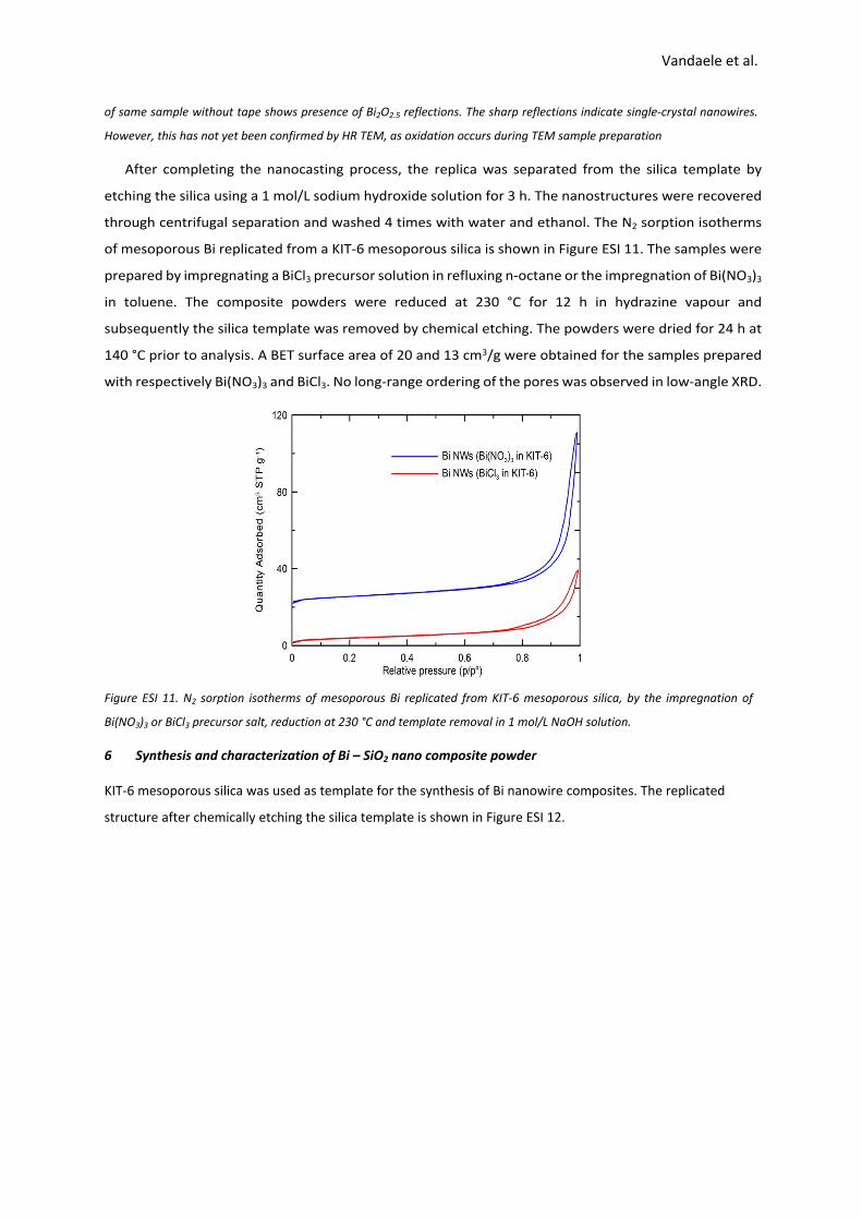
After completing the nanocasting process, the replica was separated from the silica template by
etching the silica using a 1 mol/L sodium hydroxide solution for 3 h. The nanostructures were recovered
through centrifugal separation and washed 4 times with water and ethanol. The N2 sorption isotherms
of mesoporous Bi replicated from a KIT-6 mesoporous silica is shown in Figure ESI 11. The samples were
prepared by impregnating a BiCl3 precursor solution in refluxing n-octane or the impregnation of Bi(NO3)3
in toluene. The composite powders were reduced at 230 °C for 12 h in hydrazine vapour and
subsequently the silica template was removed by chemical etching. The powders were dried for 24 h at
140 °C prior to analysis. A BET surface area of 20 and 13 cm3/g were obtained for the samples prepared
with respectively Bi(NO3)3 and BiCl3. No long-range ordering of the pores was observed in low-angle XRD.
Figure ESI 11. N2 sorption isotherms of mesoporous Bi replicated from KIT-6 mesoporous silica, by the impregnation of
Bi(NO3)3 or BiCl3 precursor salt, reduction at 230 °C and template removal in 1 mol/L NaOH solution.
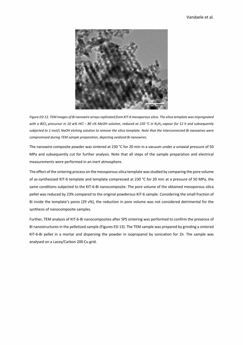
6 Synthesis and characterization of Bi – SiO2 nano composite powder
KIT-6 mesoporous silica was used as template for the synthesis of Bi nanowire composites. The replicated
structure after chemically etching the silica template is shown in Figure ESI 12.
Vandaele et al.
Figure ESI 12. TEM images of Bi nanowire arrays replicated from KIT-6 mesoporous silica. The silica template was impregnated
with a BiCl3 precursor in 10 w% HCl – 80 v% MeOH solution, reduced at 220 °C in N2H4 vapour for 12 h and subsequently
subjected to 1 mol/L NaOH etching solution to remove the silica template. Note that the interconnected Bi nanowires were
compromised during TEM sample preparation, depicting oxidized Bi nanowires.
The nanowire composite powder was sintered at 230 °C for 20 min in a vacuum under a uniaxial pressure of 50
MPa and subsequently cut for further analysis. Note that all steps of the sample preparation and electrical
measurements were performed in an inert atmosphere.
The effect of the sintering process on the mesoporous silica template was studied by comparing the pore volume
of as-synthesized KIT-6 template and template compressed at 230 °C for 20 min at a pressure of 50 MPa, the
same conditions subjected to the KIT-6-Bi nanocomposite. The pore volume of the obtained mesoporous silica
pellet was reduced by 23% compared to the original powderous KIT-6 sample. Considering the small fraction of
Bi inside the template’s pores (29 v%), the reduction in pore volume was not considered detrimental for the
synthesis of nanocomposite samples.
Further, TEM analysis of KIT-6-Bi nanocomposites after SPS sintering was performed to confirm the presence of
Bi nanostructures in the pelletized sample (Figures ESI 13). The TEM sample was prepared by grinding a sintered
KIT-6-Bi pellet in a mortar and dispersing the powder in isopropanol by sonication for 1h. The sample was
analysed on a Lacey/Carbon 200 Cu grid.

Vandaele et al.
Figure ESI 13. Typical TEM images of the nanocomposite powder after SPS sintering. Bi nanowires are confined within the template’s pores, with the presence of a leached Bi sphere at the template’s surface as indicated on the figure.
It can be seen from the TEM image in Figure ESI 13 that the Bi nanostructures remained predominantly
embedded within the silica template during the sintering process. Consequently, the presence of Bi
nanostructures within the nanocomposite sample was confirmed via both TEM analysis and electrical resistivity
measurements.
7 References
1. A. Coelho, Topas Academic v4.1, Coelho Software, Brisbane, Australia, 2007.
2. Zhao, D.Y., et al., Nonionic triblock and star diblock copolymer and oligomeric surfactant syntheses of
highly ordered, hydrothermally stable, mesoporous silica structures. Journal of the American Chemical
Society, 1998. 120(24): p. 6024-6036.
3. Kim, T.W., et al., MCM-48-like large mesoporous silicas with tailored pore structure: Facile synthesis
domain in a ternary triblock copolymer-butanol-water system. Journal of the American Chemical
Society, 2005. 127(20): p. 7601-7610.
4. Huang, X., et al., Synthesis of confined Ag nanowires within mesoporous silica via double solvent
technique and their catalytic properties. Journal of Colloid and Interface Science, 2011. 359(1): p. 40-
46.
5. Wang, Z.-J., Y. Xie, and C.-J. Liu, Synthesis and Characterization of Noble Metal (Pd, Pt, Au, Ag)
Nanostructured Materials Confined in the Channels of Mesoporous SBA-15. Journal of Physical
Chemistry C, 2008. 112(50): p. 19818-19824.
6. Littrell, D.M., D.H. Bowers, and B.J. Tatarchuk, Hydrazine reduction of transition-metal oxides. Journal of
the Chemical Society-Faraday Transactions I, 1987. 83: p. 3271-3282.
Leached Bi
Bi nanowire network

Vandaele et al.
7. Pint, C.L., et al., Rapid and scalable reduction of dense surface-supported metal-oxide catalyst with
hydrazine vapor. ACS nano, 2009. 3(7): p. 1897-905.