6-speed manual gearbox 0ag
TRANSCRIPT
Protected by copyright. C
opying
for p
rivat
e or
com
mer
cial
pur
pose
s, in
par
t or i
n w
hole
, is
not p
erm
itted
unles
s authorise
d by Volkswagen AG. Volkswagen AG does not guarantee or accept any liability with respect to the correctness ofinform
ation in this document.Copyright by Volkswagen AG.
Workshop ManualJetta 2006 ➤Golf Variant 2008 ➤6-speed manual gearbox 0AGEdition 08.2007
Service
Service Department. Technical Information

Protected by copyright. C
opying
for p
rivat
e or
com
mer
cial
pur
pose
s, in
par
t or i
n w
hole
, is
not p
erm
itted
unles
s authorise
d by Volkswagen AG. Volkswagen AG does not guarantee or accept any liability with respect to the correctness ofinform
ation in this document.Copyright by Volkswagen AG.
List of Workshop Manual Repair GroupsList of Workshop ManualRepair GroupsList of Workshop Manual Repair Groups
Repai r Group00 - Technical data30 - Clutch34 - Controls, housing35 - Gears, shafts39 - Final drive - differential
Technical information should always be available to the foremen and mechanics, because theircareful and constant adherence to the instructions is essential to ensure vehicle road-worthiness andsafety. In addition, the normal basic safety precautions for working on motor vehicles must, as amatter of course, be observed.
Service
All rights reserved.No reproduction without prior agreement from publisher.
Copyright © 2010 Volkswagen AG, Wolfsburg MEX5R007720

Protected by copyright. C
opying
for p
rivat
e or
com
mer
cial
pur
pose
s, in
par
t or i
n w
hole
, is
not p
erm
itted
unles
s authorise
d by Volkswagen AG. Volkswagen AG does not guarantee or accept any liability with respect to the correctness ofinform
ation in this document.Copyright by Volkswagen AG.
Contents
00 - Technical data . . . . . . . . . . . . . . . . . . . . . . . . . . . . . . . . . . . . . . . . . . . . . . . . . . . . 11 Gearbox identification . . . . . . . . . . . . . . . . . . . . . . . . . . . . . . . . . . . . . . . . . . . . . . . . . . . . . . 11.1 Location on gearbox . . . . . . . . . . . . . . . . . . . . . . . . . . . . . . . . . . . . . . . . . . . . . . . . . . . . . . 11.2 Identification codes, assembly allocation, capacities . . . . . . . . . . . . . . . . . . . . . . . . . . . . . . 12 Overview - power transmission . . . . . . . . . . . . . . . . . . . . . . . . . . . . . . . . . . . . . . . . . . . . . . 33 Calculating overall gear ratio “i” . . . . . . . . . . . . . . . . . . . . . . . . . . . . . . . . . . . . . . . . . . . . . . 54 General repair notes . . . . . . . . . . . . . . . . . . . . . . . . . . . . . . . . . . . . . . . . . . . . . . . . . . . . . . 64.1 Components . . . . . . . . . . . . . . . . . . . . . . . . . . . . . . . . . . . . . . . . . . . . . . . . . . . . . . . . . . . . 6
30 - Clutch . . . . . . . . . . . . . . . . . . . . . . . . . . . . . . . . . . . . . . . . . . . . . . . . . . . . . . . . . . 91 Fault finding, power transmission . . . . . . . . . . . . . . . . . . . . . . . . . . . . . . . . . . . . . . . . . . . . 92 Repairing clutch mechanism . . . . . . . . . . . . . . . . . . . . . . . . . . . . . . . . . . . . . . . . . . . . . . . . 102.1 Overview . . . . . . . . . . . . . . . . . . . . . . . . . . . . . . . . . . . . . . . . . . . . . . . . . . . . . . . . . . . . . . 102.2 Assembly overview - pedal cluster . . . . . . . . . . . . . . . . . . . . . . . . . . . . . . . . . . . . . . . . . . . . 112.3 Removing and installing over-centre spring . . . . . . . . . . . . . . . . . . . . . . . . . . . . . . . . . . . . 122.4 Removing and installing clutch pedal . . . . . . . . . . . . . . . . . . . . . . . . . . . . . . . . . . . . . . . . . . 142.5 Removing and installing mounting bracket . . . . . . . . . . . . . . . . . . . . . . . . . . . . . . . . . . . . . . 162.6 Removing and installing master cylinder . . . . . . . . . . . . . . . . . . . . . . . . . . . . . . . . . . . . . . 192.7 Removing and installing clutch position sender G476 . . . . . . . . . . . . . . . . . . . . . . . . . . . . 212.8 Assembly overview - hydraulic system . . . . . . . . . . . . . . . . . . . . . . . . . . . . . . . . . . . . . . . . 242.9 Removing and installing slave cylinder . . . . . . . . . . . . . . . . . . . . . . . . . . . . . . . . . . . . . . . . 252.10 Bleeding clutch system . . . . . . . . . . . . . . . . . . . . . . . . . . . . . . . . . . . . . . . . . . . . . . . . . . . . 273 Repairing clutch release mechanism . . . . . . . . . . . . . . . . . . . . . . . . . . . . . . . . . . . . . . . . . . 294 Repairing clutch . . . . . . . . . . . . . . . . . . . . . . . . . . . . . . . . . . . . . . . . . . . . . . . . . . . . . . . . . . 31
34 - Controls, housing . . . . . . . . . . . . . . . . . . . . . . . . . . . . . . . . . . . . . . . . . . . . . . . . . . 341 Fault finding, power transmission . . . . . . . . . . . . . . . . . . . . . . . . . . . . . . . . . . . . . . . . . . . . 342 Repairing selector mechanism . . . . . . . . . . . . . . . . . . . . . . . . . . . . . . . . . . . . . . . . . . . . . . 352.1 Installation position of selector mechanism . . . . . . . . . . . . . . . . . . . . . . . . . . . . . . . . . . . . 352.2 Removing and installing selector lever knob and cover . . . . . . . . . . . . . . . . . . . . . . . . . . . . 382.3 Removing and installing gaiter with selector lever knob and noise insulation . . . . . . . . . . 382.4 Repairing selector lever and selector lever housing (through 10.06) . . . . . . . . . . . . . . . . . . 402.5 Repairing selector lever and selector lever housing (from 11.06) . . . . . . . . . . . . . . . . . . . . 422.6 Assembly overview - removing and installing selector cables . . . . . . . . . . . . . . . . . . . . . . 472.7 Plastic relay lever . . . . . . . . . . . . . . . . . . . . . . . . . . . . . . . . . . . . . . . . . . . . . . . . . . . . . . . . 502.8 Removing and installing selector mechanism . . . . . . . . . . . . . . . . . . . . . . . . . . . . . . . . . . 512.9 Adjusting selector mechanism . . . . . . . . . . . . . . . . . . . . . . . . . . . . . . . . . . . . . . . . . . . . . . 543 Removing and installing gearbox . . . . . . . . . . . . . . . . . . . . . . . . . . . . . . . . . . . . . . . . . . . . 573.1 Removing gearbox . . . . . . . . . . . . . . . . . . . . . . . . . . . . . . . . . . . . . . . . . . . . . . . . . . . . . . . . 583.2 Installing gearbox . . . . . . . . . . . . . . . . . . . . . . . . . . . . . . . . . . . . . . . . . . . . . . . . . . . . . . . . 633.3 Torque settings . . . . . . . . . . . . . . . . . . . . . . . . . . . . . . . . . . . . . . . . . . . . . . . . . . . . . . . . . . 684 Checking gear oil . . . . . . . . . . . . . . . . . . . . . . . . . . . . . . . . . . . . . . . . . . . . . . . . . . . . . . . . 705 Dismantling and assembling gearbox . . . . . . . . . . . . . . . . . . . . . . . . . . . . . . . . . . . . . . . . 725.1 Overview - gearbox . . . . . . . . . . . . . . . . . . . . . . . . . . . . . . . . . . . . . . . . . . . . . . . . . . . . . . 725.2 Assembly overview . . . . . . . . . . . . . . . . . . . . . . . . . . . . . . . . . . . . . . . . . . . . . . . . . . . . . . . . 735.3 Assembly overview - removing and installing cover for gearbox housing and 5th and 6th
gear . . . . . . . . . . . . . . . . . . . . . . . . . . . . . . . . . . . . . . . . . . . . . . . . . . . . . . . . . . . . . . . . . . 745.4 Assembly overview - removing and installing clutch housing . . . . . . . . . . . . . . . . . . . . . . . . 765.5 Assembly overview - removing and installing input shaft, output shaft (drive pinion),
differential, selector mechanism and selector forks . . . . . . . . . . . . . . . . . . . . . . . . . . . . . . 775.6 Dismantling and assembling procedure . . . . . . . . . . . . . . . . . . . . . . . . . . . . . . . . . . . . . . . . 78
Jetta 2006 ➤ , Golf Variant 2008 ➤6-speed manual gearbox 0AG - Edition 08.2007
Contents i

Protected by copyright. C
opying
for p
rivat
e or
com
mer
cial
pur
pose
s, in
par
t or i
n w
hole
, is
not p
erm
itted
unles
s authorise
d by Volkswagen AG. Volkswagen AG does not guarantee or accept any liability with respect to the correctness ofinform
ation in this document.Copyright by Volkswagen AG.
6 Repairing gearbox housing and clutch housing . . . . . . . . . . . . . . . . . . . . . . . . . . . . . . . . . . 917 Repairing gearbox housing cover . . . . . . . . . . . . . . . . . . . . . . . . . . . . . . . . . . . . . . . . . . . . 968 Repairing selector unit . . . . . . . . . . . . . . . . . . . . . . . . . . . . . . . . . . . . . . . . . . . . . . . . . . . . 999 Dismantling and assembling selector forks . . . . . . . . . . . . . . . . . . . . . . . . . . . . . . . . . . . . 102
35 - Gears, shafts . . . . . . . . . . . . . . . . . . . . . . . . . . . . . . . . . . . . . . . . . . . . . . . . . . . . 1071 Input shaft . . . . . . . . . . . . . . . . . . . . . . . . . . . . . . . . . . . . . . . . . . . . . . . . . . . . . . . . . . . . . . 1071.1 Dismantling and assembling input shaft . . . . . . . . . . . . . . . . . . . . . . . . . . . . . . . . . . . . . . . . 1072 Output shaft . . . . . . . . . . . . . . . . . . . . . . . . . . . . . . . . . . . . . . . . . . . . . . . . . . . . . . . . . . . . 1172.1 Dismantling and assembling output shaft . . . . . . . . . . . . . . . . . . . . . . . . . . . . . . . . . . . . . . 117
39 - Final drive - differential . . . . . . . . . . . . . . . . . . . . . . . . . . . . . . . . . . . . . . . . . . . . . . 1251 Renewing flange shaft oil seals with gearbox installed . . . . . . . . . . . . . . . . . . . . . . . . . . . . 1251.1 Renewing oil seal for left flange shaft . . . . . . . . . . . . . . . . . . . . . . . . . . . . . . . . . . . . . . . . . . 1251.2 Renewing seal for right flange shaft . . . . . . . . . . . . . . . . . . . . . . . . . . . . . . . . . . . . . . . . . . 1272 Differential . . . . . . . . . . . . . . . . . . . . . . . . . . . . . . . . . . . . . . . . . . . . . . . . . . . . . . . . . . . . . . 1292.1 Dismantling and assembling differential . . . . . . . . . . . . . . . . . . . . . . . . . . . . . . . . . . . . . . . . 1292.2 Adjusting differential . . . . . . . . . . . . . . . . . . . . . . . . . . . . . . . . . . . . . . . . . . . . . . . . . . . . . . 137
Jetta 2006 ➤ , Golf Variant 2008 ➤6-speed manual gearbox 0AG - Edition 08.2007
ii Contents
Protected by copyright. C
opying
for p
rivat
e or
com
mer
cial
pur
pose
s, in
par
t or i
n w
hole
, is
not p
erm
itted
unles
s authorise
d by Volkswagen AG. Volkswagen AG does not guarantee or accept any liability with respect to the correctness ofinform
ation in this document.Copyright by Volkswagen AG.
00 – Technical data1 Gearbox identificationThe 6-speed manual gearbox 0AG is installed in the Jetta 2006 ▸and Golf Variant 2008 ▸ in conjunction with a 4-cylinder engine.Allocation ⇒ page 1
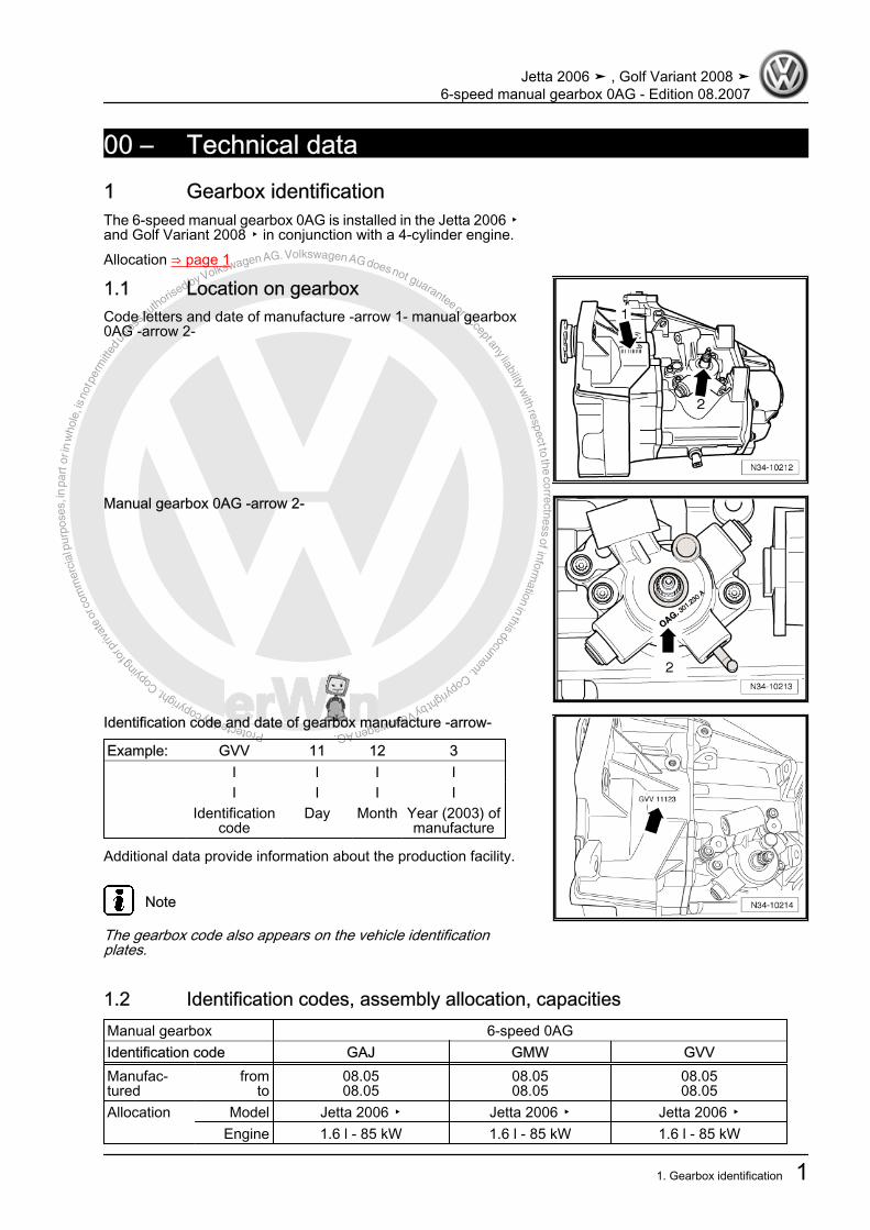
1.1 Location on gearboxCode letters and date of manufacture -arrow 1- manual gearbox0AG -arrow 2-
Manual gearbox 0AG -arrow 2-
Identification code and date of gearbox manufacture -arrow-
Example: GVV 11 12 3 I I I I I I I I Identification
codeDay Month Year (2003) of
manufacture
Additional data provide information about the production facility.
Note
The gearbox code also appears on the vehicle identificationplates.
1.2 Identification codes, assembly allocation, capacitiesManual gearbox 6-speed 0AGIdentification code GAJ GMW GVVManufac‐tured
fromto
08.0508.05
08.0508.05
08.0508.05
Allocation Model Jetta 2006 ▸ Jetta 2006 ▸ Jetta 2006 ▸ Engine 1.6 l - 85 kW 1.6 l - 85 kW 1.6 l - 85 kW
Jetta 2006 ➤ , Golf Variant 2008 ➤6-speed manual gearbox 0AG - Edition 08.2007
1. Gearbox identification 1

Protected by copyright. C
opying
for p
rivat
e or
com
mer
cial
pur
pose
s, in
par
t or i
n w
hole
, is
not p
erm
itted
unles
s authorise
d by Volkswagen AG. Volkswagen AG does not guarantee or accept any liability with respect to the correctness ofinform
ation in this document.Copyright by Volkswagen AG.
Manual gearbox 6-speed 0AGIdentification code GAJ GMW GVVRatioZ1 : Z2
Final drive 68 : 15 =4.533 68 : 15 =4.533 68 : 15 =4.533
Capacity of manual gear‐box
2.1 l 2.1 l 2.1 l
Drive shaft flange ∅ 100 mm 100 mm 100 mm
The following data can be found in the ⇒ Electronic parts cata‐logue “ETKA” .♦ Individual gear ratios♦ Gear oil♦ Clutch allocation
Manual gearbox 6-speed 0AGIdentification code HBM JHY
Manufac‐tured
fromto
08.05 11.06
Allocation Model Jetta 2006 ▸Golf Variant 2008 ▸
Jetta 2006 ▸Golf Variant 2008 ▸
Engine 1.6 l - 85 kW 1.6 l - 85 kW RatioZ1 : Z2
Final drive 68 : 15 =4.533 68 : 15 =4.533
Capacity of manual gear‐box
2.1 l 2.1 l
Drive shaft flange ∅ 100 mm 100 mm
The following data can be found in the ⇒ Electronic parts cata‐logue “ETKA” .♦ Individual gear ratios♦ Gear oil♦ Clutch allocation
Jetta 2006 ➤ , Golf Variant 2008 ➤6-speed manual gearbox 0AG - Edition 08.2007
2 Rep. Gr.00 - Technical data

Protected by copyright. C
opying
for p
rivat
e or
com
mer
cial
pur
pose
s, in
par
t or i
n w
hole
, is
not p
erm
itted
unles
s authorise
d by Volkswagen AG. Volkswagen AG does not guarantee or accept any liability with respect to the correctness ofinform
ation in this document.Copyright by Volkswagen AG.
2 Overview - power transmissionDesignation-Arrows- indicate direction of travel.
1 - Engine2 - Clutch3 - Manual gearbox4 - Input shaft5 - Output shaft6 - Differential
Gears-Arrows- indicate direction of travel.
Jetta 2006 ➤ , Golf Variant 2008 ➤6-speed manual gearbox 0AG - Edition 08.2007
2. Overview - power transmission 3

Protected by copyright. C
opying
for p
rivat
e or
com
mer
cial
pur
pose
s, in
par
t or i
n w
hole
, is
not p
erm
itted
unles
s authorise
d by Volkswagen AG. Volkswagen AG does not guarantee or accept any liability with respect to the correctness ofinform
ation in this document.Copyright by Volkswagen AG.
I - 1st gearII - 2nd gearIII - 3rd gearIV - 4th gearV - 5th gearVI - 6th gearR - Reverse gearA - Final drive
Jetta 2006 ➤ , Golf Variant 2008 ➤6-speed manual gearbox 0AG - Edition 08.2007
4 Rep. Gr.00 - Technical data

Protected by copyright. C
opying
for p
rivat
e or
com
mer
cial
pur
pose
s, in
par
t or i
n w
hole
, is
not p
erm
itted
unles
s authorise
d by Volkswagen AG. Volkswagen AG does not guarantee or accept any liability with respect to the correctness ofinform
ation in this document.Copyright by Volkswagen AG.
3 Calculating overall gear ratio “i”Example:
6th gear Final driveDrive gear ZG1 = 49 ZA1 = 16Driven gear ZG2 = 38 ZA2 = 67
i = Z2 : Z1 1)
iG = Gear ratio = ZG2 : ZG1 = 38 : 49 = 0.776
iA = Final drive ratio = ZA2 : ZA1 = 67 : 16 = 4.188
itotal = Overall ratio = iG x iA = 0.776 x 4.188 = 3.2501) Z1 = No. of teeth on driving gear, Z2 = No. of teeth on driven gear
Jetta 2006 ➤ , Golf Variant 2008 ➤6-speed manual gearbox 0AG - Edition 08.2007
3. Calculating overall gear ratio “i” 5

Protected by copyright. C
opying
for p
rivat
e or
com
mer
cial
pur
pose
s, in
par
t or i
n w
hole
, is
not p
erm
itted
unles
s authorise
d by Volkswagen AG. Volkswagen AG does not guarantee or accept any liability with respect to the correctness ofinform
ation in this document.Copyright by Volkswagen AG.
4 General repair notesTo ensure perfect and successful gearbox repairs, the greatestcare and cleanliness as well as the use of good and proper toolsis essential. Of course, the basic rules for safety also apply duringrepair work.A number of instructions generally applicable to the various repairprocedures - which were previously repeated a number of timesat various places in the workshop manual are summarised underthe topic “components” ⇒ page 6 . They apply to this workshopmanual.
4.1 Components
4.1.1 Gearbox♦ When installing the manual gearbox, ensure that the dowel
sleeves between the engine and gearbox are correctly seated.♦ When installing mounting brackets or waxed components,
clean the contact surfaces. Contact surfaces must be free ofwax and grease.
♦ Allocate bolts and other components using ⇒ Electronic partscatalogue “ETKA” .
♦ Following installation, check gear oil level♦ Capacities ⇒ page 1
4.1.2 Seals and sealing rings♦ Before installing oil seal, half-fill space between sealing lips
with sealing grease -G 052 128 A1- -arrow-.♦ The open side of the oil seal faces the side with fluid filling.♦ After installing, check oil level ⇒ page 70 .Lightly oil O-rings before installing; this prevents the rings beingcrushed when inserted.♦ Thoroughly clean parting surfaces and apply sealant -AMV
188 200 03- .♦ Apply sealant uniformly but not too thick.
4.1.3 Locking devices♦ Renew retaining rings.♦ Do not overstretch retaining rings.♦ Retaining rings must locate properly in grooves.♦ Renew spring pins. Installation position: slot longitudinal to line
of force.
Jetta 2006 ➤ , Golf Variant 2008 ➤6-speed manual gearbox 0AG - Edition 08.2007
6 Rep. Gr.00 - Technical data

Protected by copyright. C
opying
for p
rivat
e or
com
mer
cial
pur
pose
s, in
par
t or i
n w
hole
, is
not p
erm
itted
unles
s authorise
d by Volkswagen AG. Volkswagen AG does not guarantee or accept any liability with respect to the correctness ofinform
ation in this document.Copyright by Volkswagen AG.
4.1.4 Nuts and bolts♦ Loosen and tighten securing bolts and nuts for covers and
housings diagonally.♦ Do not cant especially delicate parts, such as clutch pressure
plates. Loosen and tighten bolts and nuts in stages in a diag‐onal sequence.
♦ Torque settings are specified for unoiled bolts and nuts.♦ Always renew self-locking bolts and nuts.♦ Ensure with threaded connections that contact surfaces as
well as nuts and bolts are rewaxed only after assembly, if nec‐essary.
♦ Use a thread chaser to clear residual locking fluid from allthreaded holes into which self-locking bolts are to be screwed.Otherwise there is a danger of bolts shearing when subse‐quently being removed.
4.1.5 Bearings♦ Install new tapered roller bearings as supplied and do not lu‐
bricate additionally.♦ Install needle bearings with lettered side (thicker metal) to‐
wards fitting tool.♦ Tapered roller bearings fitted to one shaft must be renewed as
a set. Use same make of bearings.♦ Heat inner races to about 100° C with the inductive heater -
VAS 6414- before installing.♦ Do not interchange outer or inner races of bearings of the
same size. The bearings are matched in pairs.
4.1.6 Shims♦ Measure shims at several points with a micrometer. The var‐
ious thicknesses make it possible to achieve the exact shimthickness required.
♦ Check for burrs and damage.♦ Install only flawless shims.
4.1.7 Synchro-rings♦ Do not interchange. When reusing synchro-rings, always fit to
the same gear.♦ Check for wear and renew if necessary.♦ Check grooves -arrow 1- of synchro-ring -A- and inner ring for
flat spots (worn grooves).♦ If synchro-rings are coated, coating must not be damaged.♦ If an intermediate ring -B- is installed, check the outer friction
surface -arrow 2- and inner friction surface -arrow 3- of thisintermediate ring for “scoring”, “signs of abnormal wear” and“blue discolouration (due to overheating)”.
♦ Check cone of synchromeshed gear for “scoring” and “signsof abnormal wear”.
♦ Moisten synchromesh mechanism with gear oil before instal‐ling.
Jetta 2006 ➤ , Golf Variant 2008 ➤6-speed manual gearbox 0AG - Edition 08.2007
4. General repair notes 7
Protected by copyright. C
opying
for p
rivat
e or
com
mer
cial
pur
pose
s, in
par
t or i
n w
hole
, is
not p
erm
itted
unles
s authorise
d by Volkswagen AG. Volkswagen AG does not guarantee or accept any liability with respect to the correctness ofinform
ation in this document.Copyright by Volkswagen AG.
4.1.8 Gear wheels♦ Before installing, clean and heat with the inductive heater -
VAS 6414- to maximum 100° C.
4.1.9 Synchromeshed gears♦ After assembly, check synchromeshed gears for slight play, or
for freedom of movement.
4.1.10 Clutch♦ Ensure that the pressure plate does not cant: loosen and tight‐
en bolts diagonally and in several gradual stages.♦ If the clutch has burnt out, thoroughly clean the bell housing
as well as the friction surface of flywheel with a cloth to reducethe smell of burnt linings.
Jetta 2006 ➤ , Golf Variant 2008 ➤6-speed manual gearbox 0AG - Edition 08.2007
8 Rep. Gr.00 - Technical data

Protected by copyright. C
opying fo
r priv
ate
or co
mm
erci
al p
urpo
ses,
in p
art o
r in
who
le, i
s no
t per
mitt
ed un
less a
uthorised by Volkswagen AG. Volkswagen AG does not guarantee or accept any liability w
ith respect to the correctness ofinformation in this docum
ent.Copyright by Volkswagen AG.
30 – Clutch1 Fault finding, power transmission– Refer to ⇒ Fault finding, power transmission; Rep. Gr. 30 ;
Complaints about clutch and clutch mechanism and ⇒ Faultfinding, power transmission; Rep. Gr. 34 ; Complaints aboutselector mechanism
Jetta 2006 ➤ , Golf Variant 2008 ➤6-speed manual gearbox 0AG - Edition 08.2007
1. Fault finding, power transmission 9
Protected by copyright. C
opying
for p
rivat
e or
com
mer
cial
pur
pose
s, in
par
t or i
n w
hole
, is
not p
erm
itted
unles
s authorise
d by Volkswagen AG. Volkswagen AG does not guarantee or accept any liability with respect to the correctness ofinform
ation in this document.Copyright by Volkswagen AG.
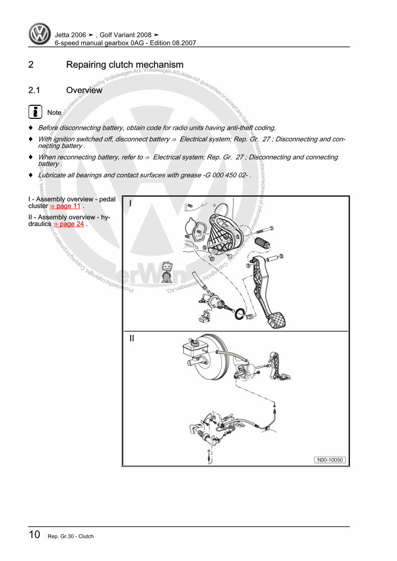
2 Repairing clutch mechanism
2.1 Overview
Note
♦ Before disconnecting battery, obtain code for radio units having anti-theft coding.♦ With ignition switched off, disconnect battery ⇒ Electrical system; Rep. Gr. 27 ; Disconnecting and con‐
necting battery .♦ When reconnecting battery, refer to ⇒ Electrical system; Rep. Gr. 27 ; Disconnecting and connecting
battery .♦ Lubricate all bearings and contact surfaces with grease -G 000 450 02- .
I - Assembly overview - pedalcluster ⇒ page 11 .II - Assembly overview - hy‐draulics ⇒ page 24 .
Jetta 2006 ➤ , Golf Variant 2008 ➤6-speed manual gearbox 0AG - Edition 08.2007
10 Rep. Gr.30 - Clutch
Protected by copyright. C
opying
for p
rivat
e or
com
mer
cial
pur
pose
s, in
par
t or i
n w
hole
, is
not p
erm
itted
unles
s authorise
d by Volkswagen AG. Volkswagen AG does not guarantee or accept any liability with respect to the correctness ofinform
ation in this document.Copyright by Volkswagen AG.
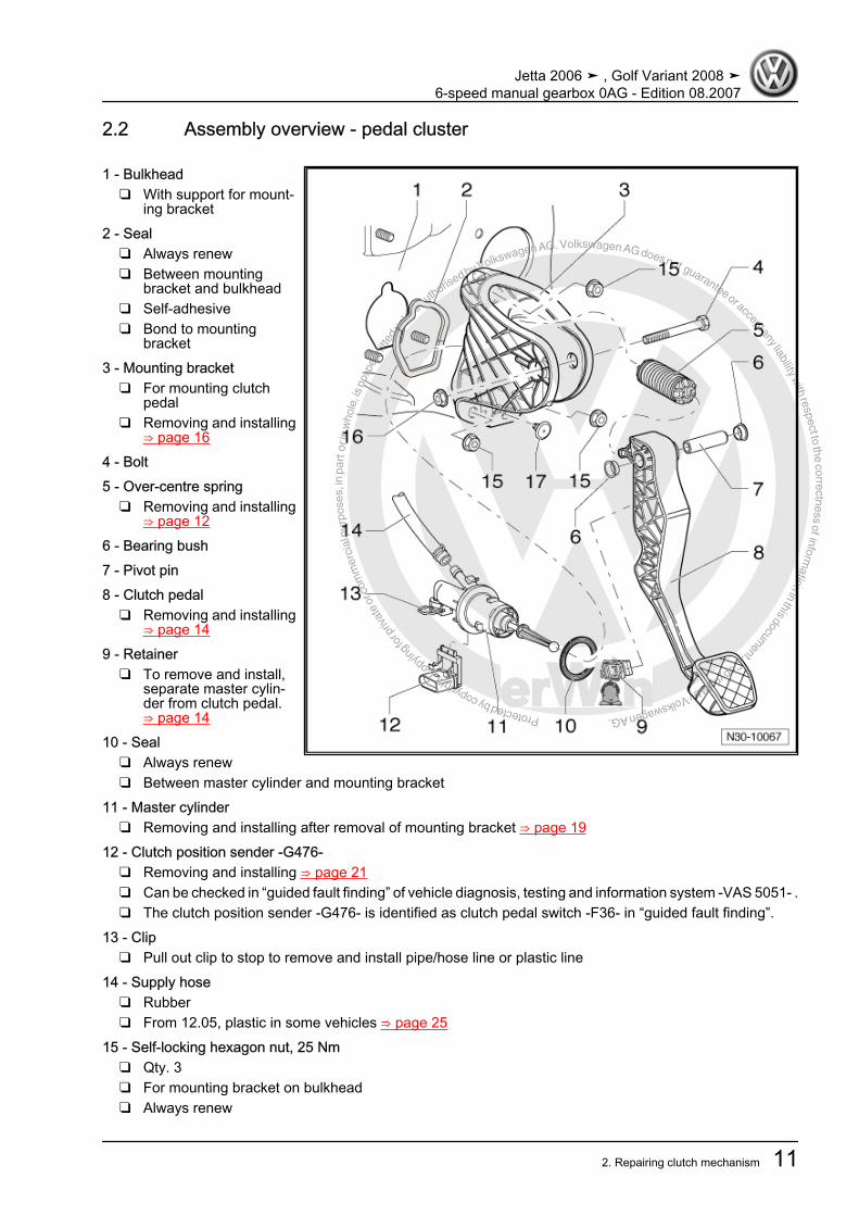
2.2 Assembly overview - pedal cluster
1 - Bulkhead❑ With support for mount‐
ing bracket2 - Seal
❑ Always renew❑ Between mounting
bracket and bulkhead❑ Self-adhesive❑ Bond to mounting
bracket3 - Mounting bracket
❑ For mounting clutchpedal
❑ Removing and installing⇒ page 16
4 - Bolt5 - Over-centre spring
❑ Removing and installing⇒ page 12
6 - Bearing bush7 - Pivot pin8 - Clutch pedal
❑ Removing and installing⇒ page 14
9 - Retainer❑ To remove and install,
separate master cylin‐der from clutch pedal.⇒ page 14
10 - Seal❑ Always renew❑ Between master cylinder and mounting bracket
11 - Master cylinder❑ Removing and installing after removal of mounting bracket ⇒ page 19
12 - Clutch position sender -G476-❑ Removing and installing ⇒ page 21❑ Can be checked in “guided fault finding” of vehicle diagnosis, testing and information system -VAS 5051- .❑ The clutch position sender -G476- is identified as clutch pedal switch -F36- in “guided fault finding”.
13 - Clip❑ Pull out clip to stop to remove and install pipe/hose line or plastic line
14 - Supply hose❑ Rubber❑ From 12.05, plastic in some vehicles ⇒ page 25
15 - Self-locking hexagon nut, 25 Nm❑ Qty. 3❑ For mounting bracket on bulkhead❑ Always renew
Jetta 2006 ➤ , Golf Variant 2008 ➤6-speed manual gearbox 0AG - Edition 08.2007
2. Repairing clutch mechanism 11
Protected by copyright. C
opying
for p
rivat
e or
com
mer
cial
pur
pose
s, in
par
t or i
n w
hole
, is
not p
erm
itted
unles
s authorise
d by Volkswagen AG. Volkswagen AG does not guarantee or accept any liability with respect to the correctness ofinform
ation in this document.Copyright by Volkswagen AG.
16 - Hexagon nut, 25 Nm❑ Always renew
17 - Stop❑ For clutch pedal
2.3 Removing and installing over-centrespring
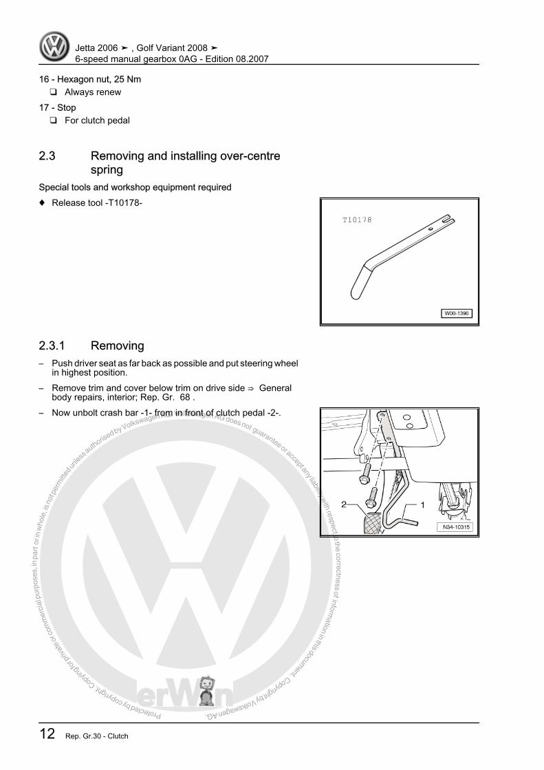
Special tools and workshop equipment required♦ Release tool -T10178-
2.3.1 Removing– Push driver seat as far back as possible and put steering wheel
in highest position.– Remove trim and cover below trim on drive side ⇒ General
body repairs, interior; Rep. Gr. 68 .– Now unbolt crash bar -1- from in front of clutch pedal -2-.
Jetta 2006 ➤ , Golf Variant 2008 ➤6-speed manual gearbox 0AG - Edition 08.2007
12 Rep. Gr.30 - Clutch
Protected by copyright. C
opying
for p
rivat
e or
com
mer
cial
pur
pose
s, in
par
t or i
n w
hole
, is
not p
erm
itted
unles
s authorise
d by Volkswagen AG. Volkswagen AG does not guarantee or accept any liability with respect to the correctness ofinform
ation in this document.Copyright by Volkswagen AG.
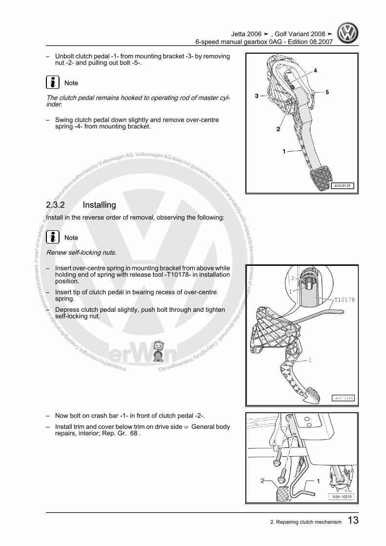
– Unbolt clutch pedal -1- from mounting bracket -3- by removingnut -2- and pulling out bolt -5-.
Note
The clutch pedal remains hooked to operating rod of master cyl‐inder.
– Swing clutch pedal down slightly and remove over-centrespring -4- from mounting bracket.
2.3.2 InstallingInstall in the reverse order of removal, observing the following:
Note
Renew self-locking nuts.
– Insert over-centre spring in mounting bracket from above whileholding end of spring with release tool -T10178- in installationposition.
– Insert tip of clutch pedal in bearing recess of over-centrespring.
– Depress clutch pedal slightly, push bolt through and tightenself-locking nut.
– Now bolt on crash bar -1- in front of clutch pedal -2-.– Install trim and cover below trim on drive side ⇒ General body
repairs, interior; Rep. Gr. 68 .
Jetta 2006 ➤ , Golf Variant 2008 ➤6-speed manual gearbox 0AG - Edition 08.2007
2. Repairing clutch mechanism 13

Protected by copyright. C
opying
for p
rivat
e or
com
mer
cial
pur
pose
s, in
par
t or i
n w
hole
, is
not p
erm
itted
unles
s authorise
d by Volkswagen AG. Volkswagen AG does not guarantee or accept any liability with respect to the correctness ofinform
ation in this document.Copyright by Volkswagen AG.
2.3.3 Torque settingsComponent NmClutch pedal to mounting bracket♦ Renew self-locking nuts
25
Crash bar to steering column mountingbracket
10
2.4 Removing and installing clutch pedalSpecial tools and workshop equipment required♦ Pliers -T10005-
♦ Release tool -T10178-
2.4.1 Removing– Push driver seat as far back as possible and put steering wheel
in highest position.– Remove trim and cover below trim on drive side ⇒ General
body repairs, interior; Rep. Gr. 68 .– Now unbolt crash bar -1- from in front of clutch pedal -2-.
Jetta 2006 ➤ , Golf Variant 2008 ➤6-speed manual gearbox 0AG - Edition 08.2007
14 Rep. Gr.30 - Clutch

Protected by copyright. C
opying
for p
rivat
e or
com
mer
cial
pur
pose
s, in
par
t or i
n w
hole
, is
not p
erm
itted
unles
s authorise
d by Volkswagen AG. Volkswagen AG does not guarantee or accept any liability with respect to the correctness ofinform
ation in this document.Copyright by Volkswagen AG.
– Unbolt clutch pedal -1- from mounting bracket -3- by removingnut -2- and pulling out bolt -5-.
– Swing clutch pedal forward slightly and remove over-centrespring -4- from mounting bracket.
– Release clutch pedal from master cylinder with pliers -T10005- .
– Remove clutch pedal.
2.4.2 InstallingInstall in the reverse order of removal, observing the following:
Note
Renew self-locking nuts.
– Attach retainer -2- to master cylinder operating rod -1-.– Press retainer into notch in clutch pedal -3- until it can be heard
to engage.
Jetta 2006 ➤ , Golf Variant 2008 ➤6-speed manual gearbox 0AG - Edition 08.2007
2. Repairing clutch mechanism 15
Protected by copyright. C
opying
for p
rivat
e or
com
mer
cial
pur
pose
s, in
par
t or i
n w
hole
, is
not p
erm
itted
unles
s authorise
d by Volkswagen AG. Volkswagen AG does not guarantee or accept any liability with respect to the correctness ofinform
ation in this document.Copyright by Volkswagen AG.
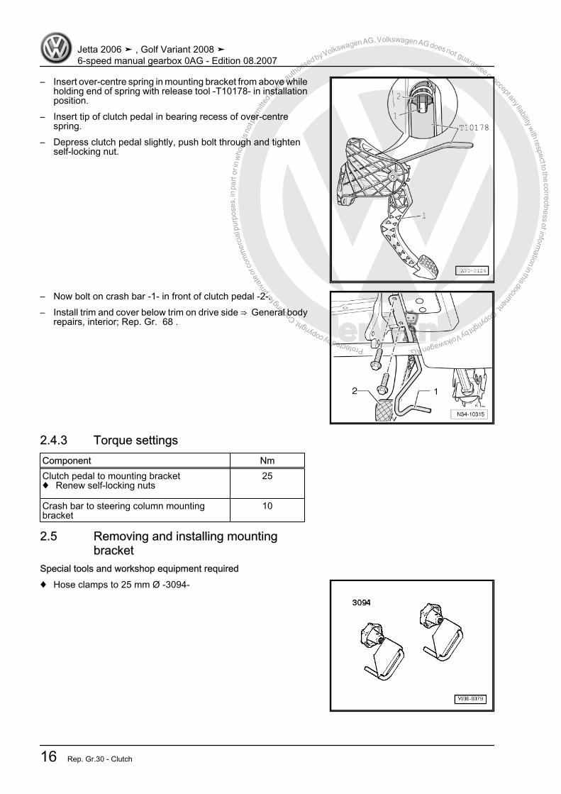
– Insert over-centre spring in mounting bracket from above whileholding end of spring with release tool -T10178- in installationposition.
– Insert tip of clutch pedal in bearing recess of over-centrespring.
– Depress clutch pedal slightly, push bolt through and tightenself-locking nut.
– Now bolt on crash bar -1- in front of clutch pedal -2-.– Install trim and cover below trim on drive side ⇒ General body
repairs, interior; Rep. Gr. 68 .
2.4.3 Torque settingsComponent NmClutch pedal to mounting bracket♦ Renew self-locking nuts
25
Crash bar to steering column mountingbracket
10
2.5 Removing and installing mountingbracket
Special tools and workshop equipment required♦ Hose clamps to 25 mm Ø -3094-
Jetta 2006 ➤ , Golf Variant 2008 ➤6-speed manual gearbox 0AG - Edition 08.2007
16 Rep. Gr.30 - Clutch
Protected by copyright. C
opying
for p
rivat
e or
com
mer
cial
pur
pose
s, in
par
t or i
n w
hole
, is
not p
erm
itted
unles
s authorise
d by Volkswagen AG. Volkswagen AG does not guarantee or accept any liability with respect to the correctness ofinform
ation in this document.Copyright by Volkswagen AG.
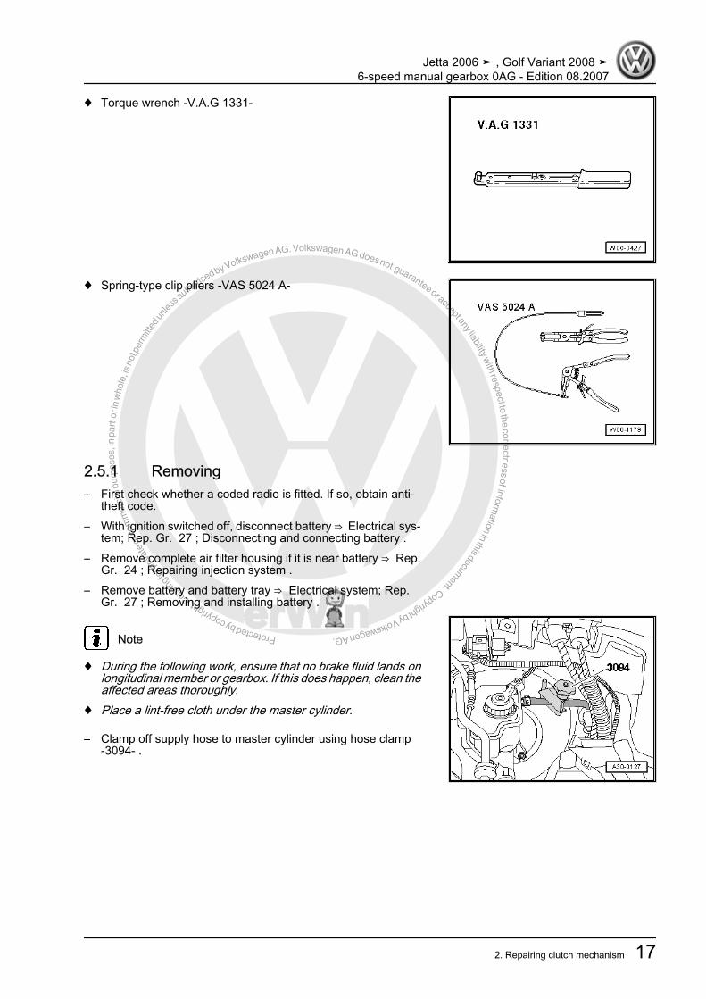
♦ Torque wrench -V.A.G 1331-
♦ Spring-type clip pliers -VAS 5024 A-
2.5.1 Removing– First check whether a coded radio is fitted. If so, obtain anti-
theft code.– With ignition switched off, disconnect battery ⇒ Electrical sys‐
tem; Rep. Gr. 27 ; Disconnecting and connecting battery .– Remove complete air filter housing if it is near battery ⇒ Rep.
Gr. 24 ; Repairing injection system .– Remove battery and battery tray ⇒ Electrical system; Rep.
Gr. 27 ; Removing and installing battery .
Note
♦ During the following work, ensure that no brake fluid lands onlongitudinal member or gearbox. If this does happen, clean theaffected areas thoroughly.
♦ Place a lint-free cloth under the master cylinder.
– Clamp off supply hose to master cylinder using hose clamp-3094- .
Jetta 2006 ➤ , Golf Variant 2008 ➤6-speed manual gearbox 0AG - Edition 08.2007
2. Repairing clutch mechanism 17
Protected by copyright. C
opying
for p
rivat
e or
com
mer
cial
pur
pose
s, in
par
t or i
n w
hole
, is
not p
erm
itted
unles
s authorise
d by Volkswagen AG. Volkswagen AG does not guarantee or accept any liability with respect to the correctness ofinform
ation in this document.Copyright by Volkswagen AG.
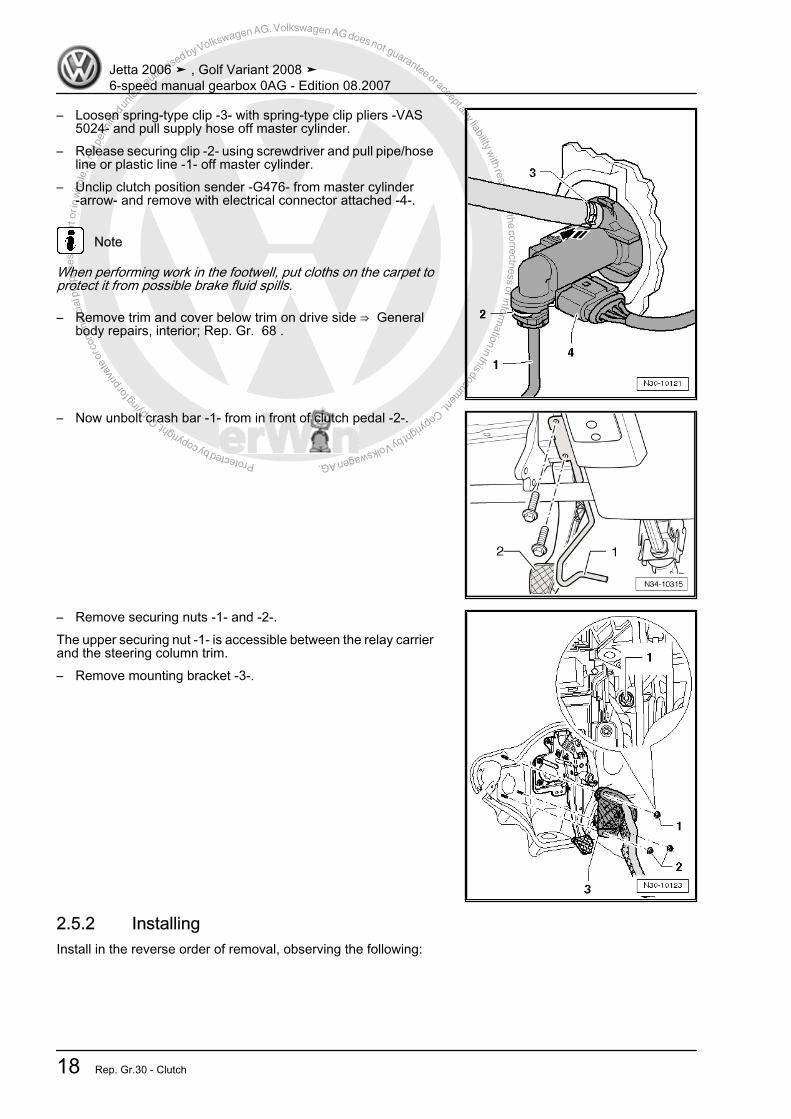
– Loosen spring-type clip -3- with spring-type clip pliers -VAS5024- and pull supply hose off master cylinder.
– Release securing clip -2- using screwdriver and pull pipe/hoseline or plastic line -1- off master cylinder.
– Unclip clutch position sender -G476- from master cylinder-arrow- and remove with electrical connector attached -4-.
Note
When performing work in the footwell, put cloths on the carpet toprotect it from possible brake fluid spills.
– Remove trim and cover below trim on drive side ⇒ Generalbody repairs, interior; Rep. Gr. 68 .
– Now unbolt crash bar -1- from in front of clutch pedal -2-.
– Remove securing nuts -1- and -2-.The upper securing nut -1- is accessible between the relay carrierand the steering column trim.– Remove mounting bracket -3-.
2.5.2 InstallingInstall in the reverse order of removal, observing the following:
Jetta 2006 ➤ , Golf Variant 2008 ➤6-speed manual gearbox 0AG - Edition 08.2007
18 Rep. Gr.30 - Clutch
Protected by copyright. C
opying
for p
rivat
e or
com
mer
cial
pur
pose
s, in
par
t or i
n w
hole
, is
not p
erm
itted
unles
s authorise
d by Volkswagen AG. Volkswagen AG does not guarantee or accept any liability with respect to the correctness ofinform
ation in this document.Copyright by Volkswagen AG.
Note
♦ Renew self-locking nuts.♦ Renew hose clips.♦ Allocate all components according to ⇒ Electronic parts cata‐
logue “ETKA” .
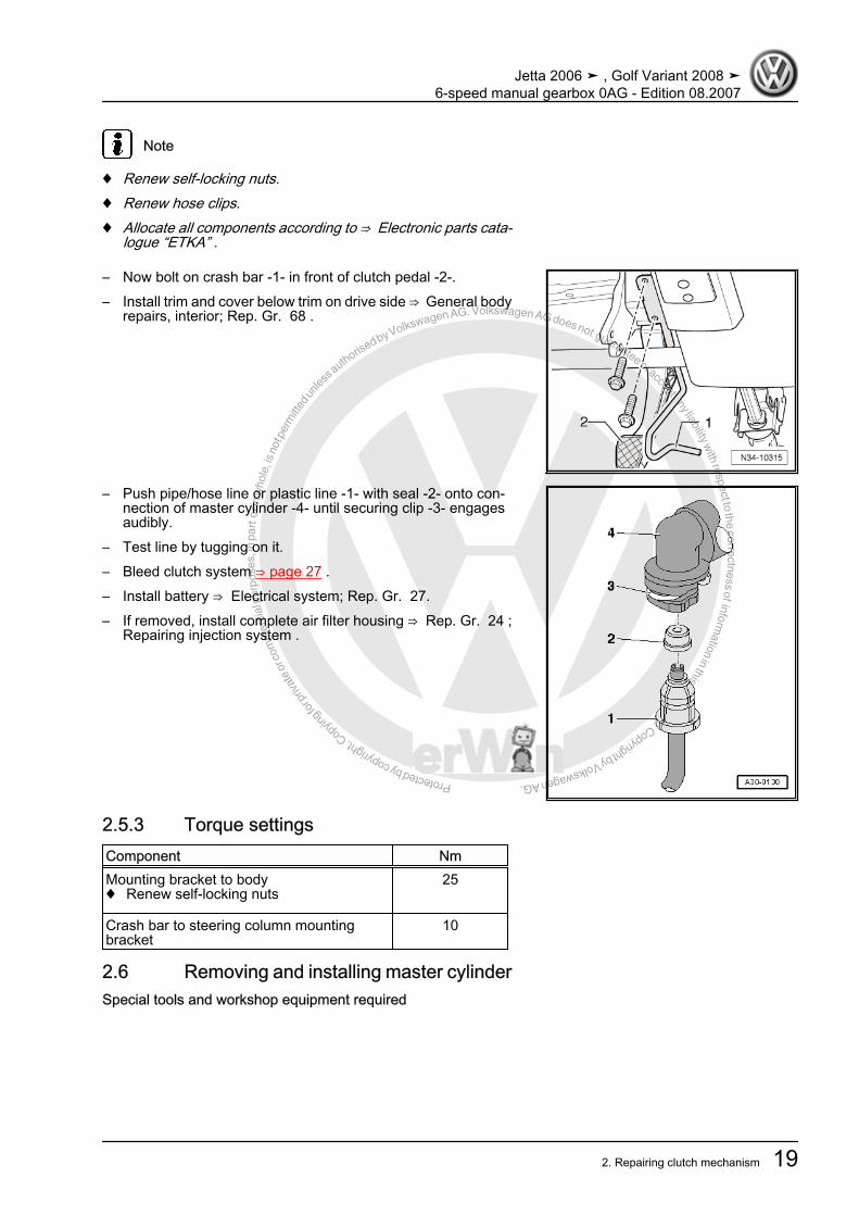
– Now bolt on crash bar -1- in front of clutch pedal -2-.– Install trim and cover below trim on drive side ⇒ General body
repairs, interior; Rep. Gr. 68 .
– Push pipe/hose line or plastic line -1- with seal -2- onto con‐nection of master cylinder -4- until securing clip -3- engagesaudibly.
– Test line by tugging on it.– Bleed clutch system ⇒ page 27 .– Install battery ⇒ Electrical system; Rep. Gr. 27.– If removed, install complete air filter housing ⇒ Rep. Gr. 24 ;
Repairing injection system .
2.5.3 Torque settingsComponent NmMounting bracket to body♦ Renew self-locking nuts
25
Crash bar to steering column mountingbracket
10
2.6 Removing and installing master cylinderSpecial tools and workshop equipment required
Jetta 2006 ➤ , Golf Variant 2008 ➤6-speed manual gearbox 0AG - Edition 08.2007
2. Repairing clutch mechanism 19
Protected by copyright. C
opying
for p
rivat
e or
com
mer
cial
pur
pose
s, in
par
t or i
n w
hole
, is
not p
erm
itted
unles
s authorise
d by Volkswagen AG. Volkswagen AG does not guarantee or accept any liability with respect to the correctness ofinform
ation in this document.Copyright by Volkswagen AG.
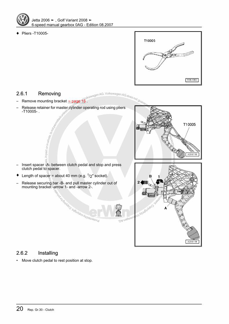
♦ Pliers -T10005-
2.6.1 Removing– Remove mounting bracket ⇒ page 16 .– Release retainer for master cylinder operating rod using pliers
-T10005- .
– Insert spacer -A- between clutch pedal and stop and pressclutch pedal to spacer.
♦ Length of spacer = about 40 mm (e.g. 1/2" socket).
– Release securing bar -B- and pull master cylinder out ofmounting bracket -arrow 1- and -arrow 2-.
2.6.2 Installing• Move clutch pedal to rest position at stop.
Jetta 2006 ➤ , Golf Variant 2008 ➤6-speed manual gearbox 0AG - Edition 08.2007
20 Rep. Gr.30 - Clutch

Protected by copyright. C
opying
for p
rivat
e or
com
mer
cial
pur
pose
s, in
par
t or i
n w
hole
, is
not p
erm
itted
unles
s authorise
d by Volkswagen AG. Volkswagen AG does not guarantee or accept any liability with respect to the correctness ofinform
ation in this document.Copyright by Volkswagen AG.
– Attach retainer -2- to master cylinder operating rod -1-.
– Insert spacer -A- between clutch pedal and stop and pressclutch pedal to spacer.
♦ Length of spacer = about 40 mm (e.g. 1/2" socket).
– Engage master cylinder in mounting bracket -arrow 1- and-arrow 2-.
– Press master cylinder operating rod -1- in direction of arrowuntil retainer -2- engages audibly in clutch pedal.
– Install mounting bracket ⇒ page 16 .
2.7 Removing and installing clutch positionsender -G476-
Special tools and workshop equipment required
Jetta 2006 ➤ , Golf Variant 2008 ➤6-speed manual gearbox 0AG - Edition 08.2007
2. Repairing clutch mechanism 21

Protected by copyright. C
opying
for p
rivat
e or
com
mer
cial
pur
pose
s, in
par
t or i
n w
hole
, is
not p
erm
itted
unles
s authorise
d by Volkswagen AG. Volkswagen AG does not guarantee or accept any liability with respect to the correctness ofinform
ation in this document.Copyright by Volkswagen AG.
♦ Hose clamps -3094-
2.7.1 Removing– First check whether a coded radio is fitted. If so, obtain anti-
theft code.– Remove complete air filter housing if it is near battery ⇒ Rep.
Gr. 24 ; Repairing injection system .– Remove battery, battery cover and battery tray ⇒ Electrical
system; Rep. Gr. 27 ; Removing and installing battery .If a pipe/hose line or plastic line -1- with a round component isinstalled directly beneath the master cylinder, the pipe/hose lineor plastic line must be removed.
Note
♦ During the following work, ensure that no brake fluid lands onlongitudinal member or gearbox. If this does happen, clean theaffected areas thoroughly.
♦ Place a lint-free cloth under the master cylinder.
– Clamp off supply hose to master cylinder using hose clamp-3094- .
Jetta 2006 ➤ , Golf Variant 2008 ➤6-speed manual gearbox 0AG - Edition 08.2007
22 Rep. Gr.30 - Clutch
Protected by copyright. C
opying
for p
rivat
e or
com
mer
cial
pur
pose
s, in
par
t or i
n w
hole
, is
not p
erm
itted
unles
s authorise
d by Volkswagen AG. Volkswagen AG does not guarantee or accept any liability with respect to the correctness ofinform
ation in this document.Copyright by Volkswagen AG.
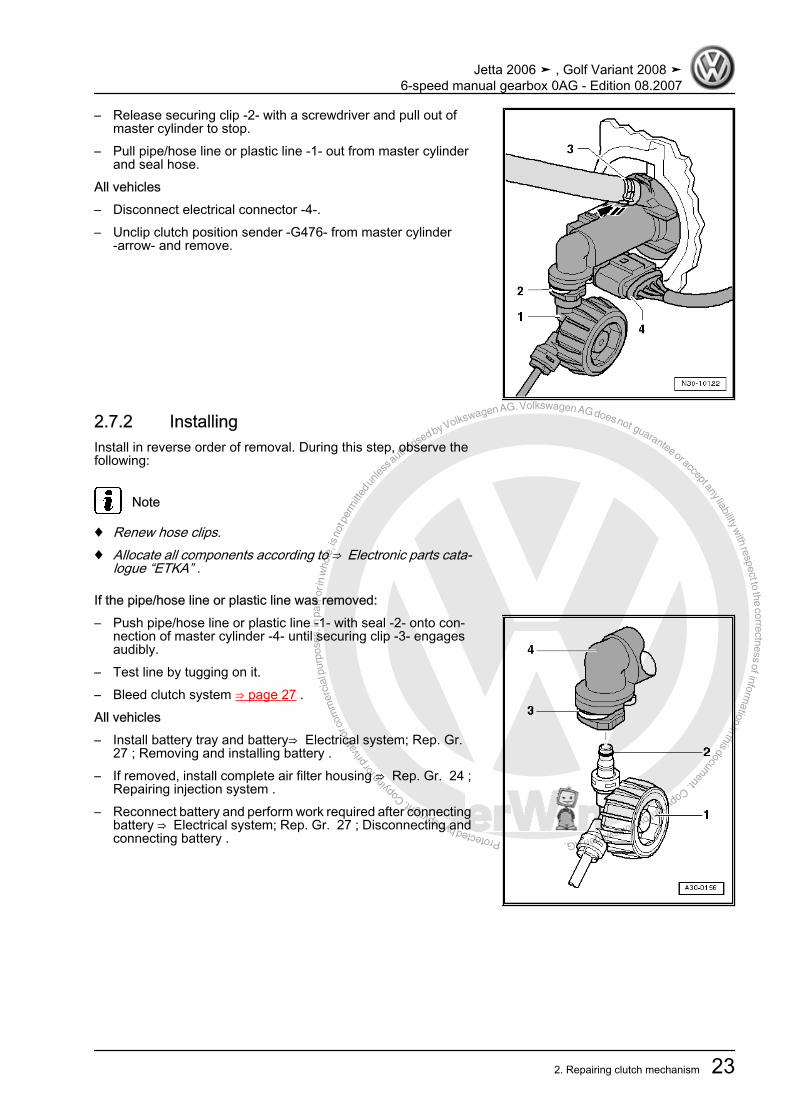
– Release securing clip -2- with a screwdriver and pull out ofmaster cylinder to stop.
– Pull pipe/hose line or plastic line -1- out from master cylinderand seal hose.
All vehicles– Disconnect electrical connector -4-.– Unclip clutch position sender -G476- from master cylinder
-arrow- and remove.
2.7.2 InstallingInstall in reverse order of removal. During this step, observe thefollowing:
Note
♦ Renew hose clips.♦ Allocate all components according to ⇒ Electronic parts cata‐
logue “ETKA” .
If the pipe/hose line or plastic line was removed:– Push pipe/hose line or plastic line -1- with seal -2- onto con‐
nection of master cylinder -4- until securing clip -3- engagesaudibly.
– Test line by tugging on it.– Bleed clutch system ⇒ page 27 .All vehicles– Install battery tray and battery⇒ Electrical system; Rep. Gr.
27 ; Removing and installing battery .– If removed, install complete air filter housing ⇒ Rep. Gr. 24 ;
Repairing injection system .– Reconnect battery and perform work required after connecting
battery ⇒ Electrical system; Rep. Gr. 27 ; Disconnecting andconnecting battery .
Jetta 2006 ➤ , Golf Variant 2008 ➤6-speed manual gearbox 0AG - Edition 08.2007
2. Repairing clutch mechanism 23

Protected by copyright. C
opying
for p
rivat
e or
com
mer
cial
pur
pose
s, in
par
t or i
n w
hole
, is
not p
erm
itted
unles
s authorise
d by Volkswagen AG. Volkswagen AG does not guarantee or accept any liability with respect to the correctness ofinform
ation in this document.Copyright by Volkswagen AG.
2.8 Assembly overview - hydraulic system
1 - Brake fluid reservoir2 - Spring-type clip3 - Supply hose
❑ Rubber❑ From 12.05, plastic in
some vehicles⇒ page 25
4 - Master cylinder❑ Removing and installing
⇒ page 195 - Clip
❑ Pull clip out to stop to re‐move or install line be‐tween master and slavecylinders
6 - Retainer❑ To remove and install,
separate master cylin‐der from clutch pedal.⇒ page 14
7 - Clutch pedal❑ Removing and installing
⇒ page 148 - Self-locking hexagon nut,25 Nm
❑ Mounting bracket tobody
❑ Always renew9 - O-ring
❑ Pull onto line connection❑ Insert with brake fluid❑ Seals, O-rings depending on configuration of line connections ⇒ page 25❑ Allocation ⇒ Electronic parts catalogue “ETKA”
10 - Seal❑ Pull onto line connection❑ Insert with brake fluid❑ Seals, O-rings depending on configuration of line connections ⇒ page 25❑ Allocation ⇒ Electronic parts catalogue “ETKA”
11 - Pipe/hose line❑ Allocation ⇒ Electronic parts catalogue “ETKA”❑ To remove, remove battery and battery tray ⇒ Electrical system; Rep. Gr. 27 ; Removing and installing
battery .12 - Retainer
❑ For pipe/hose line ⇒ Item 11 (page 24)❑ Secured to body.
13 - Plastic line❑ Allocation ⇒ Electronic parts catalogue “ETKA”❑ To remove, remove battery and battery tray ⇒ Electrical system; Rep. Gr. 27 ; Removing and installing
battery .
Jetta 2006 ➤ , Golf Variant 2008 ➤6-speed manual gearbox 0AG - Edition 08.2007
24 Rep. Gr.30 - Clutch
Protected by copyright. C
opying
for p
rivat
e or
com
mer
cial
pur
pose
s, in
par
t or i
n w
hole
, is
not p
erm
itted
unles
s authorise
d by Volkswagen AG. Volkswagen AG does not guarantee or accept any liability with respect to the correctness ofinform
ation in this document.Copyright by Volkswagen AG.
14 - Clip❑ Pull clip out to stop to remove or install line between master and slave cylinders
15 - Slave cylinder❑ Removing and installing ⇒ page 25
16 - Dust cap17 - Bleeder valve
❑ Bleeding clutch system ⇒ page 2718 - Gearbox19 - Hexagon bolt, 20 Nm20 - Retainer
❑ For pipe/hose line ⇒ Item 11 (page 24)
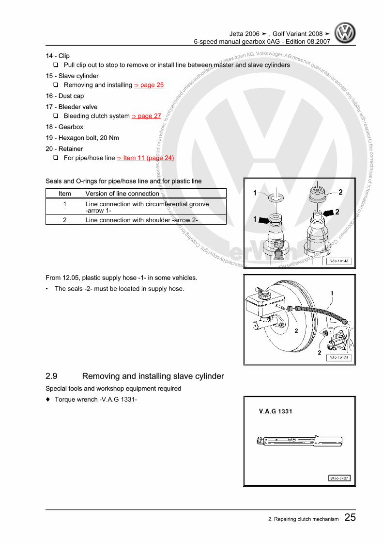
Seals and O-rings for pipe/hose line and for plastic line
Item Version of line connection1 Line connection with circumferential groove
-arrow 1-2 Line connection with shoulder -arrow 2-
From 12.05, plastic supply hose -1- in some vehicles.• The seals -2- must be located in supply hose.
2.9 Removing and installing slave cylinderSpecial tools and workshop equipment required♦ Torque wrench -V.A.G 1331-
Jetta 2006 ➤ , Golf Variant 2008 ➤6-speed manual gearbox 0AG - Edition 08.2007
2. Repairing clutch mechanism 25

Protected by copyright. C
opying
for p
rivat
e or
com
mer
cial
pur
pose
s, in
par
t or i
n w
hole
, is
not p
erm
itted
unles
s authorise
d by Volkswagen AG. Volkswagen AG does not guarantee or accept any liability with respect to the correctness ofinform
ation in this document.Copyright by Volkswagen AG.
2.9.1 Removing– First check whether a coded radio is fitted. If so, obtain anti-
theft code.– With ignition switched off, disconnect battery ⇒ Electrical sys‐
tem; Rep. Gr. 27 ; Disconnecting and connecting battery .– Remove complete air filter housing if it is near slave cylinder
⇒ Rep. Gr. 24 ; Repairing injection system .– Remove securing clip for gear selector cable -arrow 1- from
gearbox selector lever -A-.– Pull gear selector cable from pin.Metal relay lever– Remove securing clip -arrow 2- for gate selector cable from
relay lever -B-.– Pull gate selector cable from pin.– Pull securing clip -arrow 3- off relay lever -B- and remove relay
lever.Plastic relay lever– Remove relay lever together with cable end-piece from gear‐
box ⇒ page 50 .Continuation for all– Remove gearbox selector lever -A- by removing nut
-arrow 4-.
– Remove cable support bracket from gearbox -arrows-.– Then tie up selector cable and gate cable.– Place a lint-free cloth under slave cylinder.
– Pull clip -A- for line between master and slave cylinders out ofslave cylinder to stop.
– Pull line between master and slave cylinders out of support-C-, if present.
– Pull line between master and slave cylinders -B- out of slavecylinder and seal opening.
– Unbolt slave cylinder -arrows- and remove.
Note
Do not depress clutch pedal.
Jetta 2006 ➤ , Golf Variant 2008 ➤6-speed manual gearbox 0AG - Edition 08.2007
26 Rep. Gr.30 - Clutch

Protected by copyright. C
opying
for p
rivat
e or
com
mer
cial
pur
pose
s, in
par
t or i
n w
hole
, is
not p
erm
itted
unles
s authorise
d by Volkswagen AG. Volkswagen AG does not guarantee or accept any liability with respect to the correctness ofinform
ation in this document.Copyright by Volkswagen AG.
2.9.2 InstallingInstall in the reverse order of removal, observing the following:– Install slave cylinder and tighten bolts -arrows- to specified
torque ⇒ Item 19 (page 25) .– Insert line between master and slave cylinders -B- into slave
cylinder to stop.– Push securing clip -A- into line between master and slave cyl‐
inders to stop.– Test pipe/hose line by tugging on it.– Press line between master and slave cylinders into mounting
-C-, if present, to stop on gearbox.– Bleed clutch system after installing slave cylinder
⇒ page 27 .Assembling selector mechanism ⇒ page 51 .Adjusting selector mechanism ⇒ page 54 .– If removed, install complete air filter housing ⇒ Rep. Gr. 24 ;
Repairing injection system .– Connect battery earth ⇒ Electrical system; Rep. Gr. 27 ; Bat‐
tery; Disconnecting and connecting battery .
2.10 Bleeding clutch systemSpecial tools and workshop equipment required♦ Brake filling and bleeding equipment -VAS 5234- or
♦ Brake filling and bleeding equipment -V.A.G 1869-
Note
Prefilling system is not necessary!
Jetta 2006 ➤ , Golf Variant 2008 ➤6-speed manual gearbox 0AG - Edition 08.2007
2. Repairing clutch mechanism 27

Protected by copyright. C
opying
for p
rivat
e or
com
mer
cial
pur
pose
s, in
par
t or i
n w
hole
, is
not p
erm
itted
unles
s authorise
d by Volkswagen AG. Volkswagen AG does not guarantee or accept any liability with respect to the correctness ofinform
ation in this document.Copyright by Volkswagen AG.
Specifications for brake fluid ⇒ Brake systems; Rep. Gr. 47 ;Bleeding brake system .– Remove complete air filter housing if it hinders access to slave
cylinder ⇒ Rep. Gr. 24 ; Repairing injection system .– Connect brake filling and bleeding equipment -VAS 5234- or
-V.A.G 1869- .To bleed system, use 670 mm bleeder hose -V.A.G 1238/B3- ifnecessary.– Connect bleeder hose to collector bottle of brake bleeding
equipment.– Connect bleed hose to bleed valve -arrow-.– Pressurise system to 2 bar.– Open bleeder valve.– Bleed off about 100 cm3 brake fluid.– Close bleeder valve.– Rapidly operate pedal from stop to stop 10 to 15 times.– Open bleeder valve.– Bleed off an additional 50 cm3 brake fluid.– Close bleeder valve.– Depress clutch pedal several times after completion of bleed‐
ing process.– Install, if necessary, complete air filter housing ⇒ Rep. Gr.
24 ; Repairing injection system .
Jetta 2006 ➤ , Golf Variant 2008 ➤6-speed manual gearbox 0AG - Edition 08.2007
28 Rep. Gr.30 - Clutch

Protected by copyright. C
opying
for p
rivat
e or
com
mer
cial
pur
pose
s, in
par
t or i
n w
hole
, is
not p
erm
itted
unles
s authorise
d by Volkswagen AG. Volkswagen AG does not guarantee or accept any liability with respect to the correctness ofinform
ation in this document.Copyright by Volkswagen AG.
3 Repairing clutch release mechanismSpecial tools and workshop equipment required♦ Torque wrench -V.A.G 1331-
1 - Release bearing❑ Remove and install to‐
gether with clutch re‐lease lever⇒ Item 3 (page 29)and guide sleeve⇒ Item 5 (page 29)⇒ page 30 to⇒ page 30
❑ Do not wash out bear‐ing; wipe only
❑ Renew noisy bearings2 - Bolt, 5 Nm then turn 90° fur‐ther
❑ Always renew3 - Clutch release lever
❑ Remove and install to‐gether with releasebearing⇒ Item 1 (page 29) andguide sleeve⇒ Item 5 (page 29)⇒ page 30 to⇒ page 30
❑ Remove old grease4 - Retaining spring
❑ Secure to clutch releaselever
5 - Guide sleeve❑ Remove and install to‐
gether with releasebearing⇒ Item 1 (page 29) andguide sleeve⇒ Item 5 (page 29)⇒ page 30 to ⇒ page 30
6 - Input shaft seal❑ Removing and installing ⇒ page 91
7 - Ball stud, 20 Nm❑ Remove old grease
Jetta 2006 ➤ , Golf Variant 2008 ➤6-speed manual gearbox 0AG - Edition 08.2007
3. Repairing clutch release mechanism 29
Protected by copyright. C
opying fo
r priv
ate
or co
mm
erci
al p
urpo
ses,
in p
art o
r in
who
le, i
s no
t per
mitt
ed un
less a
uthorised by Volkswagen AG. Volkswagen AG does not guarantee or accept any liability w
ith respect to the correctness ofinformation in this docum
ent.Copyright by Volkswagen AG.
❑ Lubricate with grease -G 000 100-8 - Gearbox9 - Hexagon bolt, 20 Nm10 - Retainer
❑ For pipe/hose line ⇒ Item 11 (page 24)11 - Slave cylinder
❑ Removing and installing ⇒ page 25
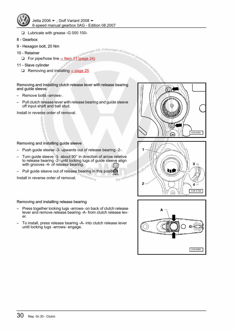
Removing and installing clutch release lever with release bearingand guide sleeve– Remove bolts -arrows-.– Pull clutch release lever with release bearing and guide sleeve
off input shaft and ball stud.Install in reverse order of removal.
Removing and installing guide sleeve– Push guide sleeve -3- upwards out of release bearing -2-.– Turn guide sleeve -3- about 90° in direction of arrow relative
to release bearing -2- until locking lugs of guide sleeve alignwith grooves -4- of release bearing.
– Pull guide sleeve out of release bearing in this position.Install in reverse order of removal.
Removing and installing release bearing– Press together locking lugs -arrows- on back of clutch release
lever and remove release bearing -A- from clutch release lev‐er.
– To install, press release bearing -A- into clutch release leveruntil locking lugs -arrows- engage.
Jetta 2006 ➤ , Golf Variant 2008 ➤6-speed manual gearbox 0AG - Edition 08.2007
30 Rep. Gr.30 - Clutch
Protected by copyright. C
opying
for p
rivat
e or
com
mer
cial
pur
pose
s, in
par
t or i
n w
hole
, is
not p
erm
itted
unles
s authorise
d by Volkswagen AG. Volkswagen AG does not guarantee or accept any liability with respect to the correctness ofinform
ation in this document.Copyright by Volkswagen AG.
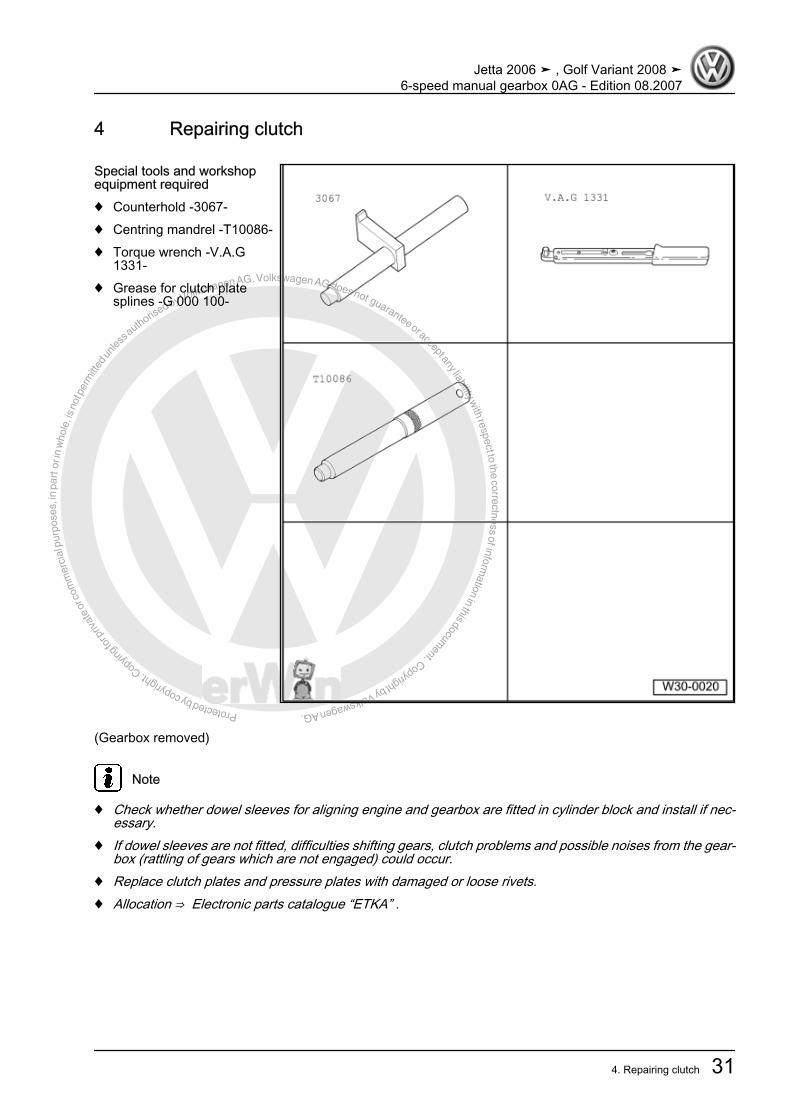
4 Repairing clutch
Special tools and workshopequipment required♦ Counterhold -3067-♦ Centring mandrel -T10086-♦ Torque wrench -V.A.G
1331-♦ Grease for clutch plate
splines -G 000 100-
(Gearbox removed)
Note
♦ Check whether dowel sleeves for aligning engine and gearbox are fitted in cylinder block and install if nec‐essary.
♦ If dowel sleeves are not fitted, difficulties shifting gears, clutch problems and possible noises from the gear‐box (rattling of gears which are not engaged) could occur.
♦ Replace clutch plates and pressure plates with damaged or loose rivets.♦ Allocation ⇒ Electronic parts catalogue “ETKA” .
Jetta 2006 ➤ , Golf Variant 2008 ➤6-speed manual gearbox 0AG - Edition 08.2007
4. Repairing clutch 31
Protected by copyright. C
opying
for p
rivat
e or
com
mer
cial
pur
pose
s, in
par
t or i
n w
hole
, is
not p
erm
itted
unles
s authorise
d by Volkswagen AG. Volkswagen AG does not guarantee or accept any liability with respect to the correctness ofinform
ation in this document.Copyright by Volkswagen AG.
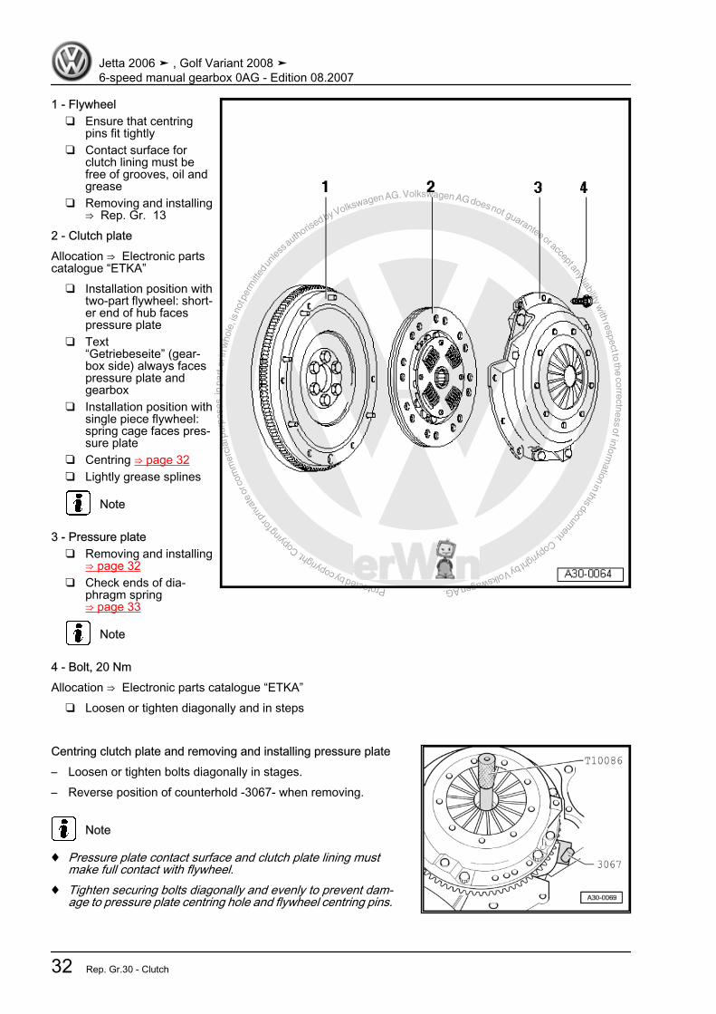
1 - Flywheel❑ Ensure that centring
pins fit tightly❑ Contact surface for
clutch lining must befree of grooves, oil andgrease
❑ Removing and installing⇒ Rep. Gr. 13
2 - Clutch plateAllocation ⇒ Electronic partscatalogue “ETKA”
❑ Installation position withtwo-part flywheel: short‐er end of hub facespressure plate
❑ Text“Getriebeseite” (gear‐box side) always facespressure plate andgearbox
❑ Installation position withsingle piece flywheel:spring cage faces pres‐sure plate
❑ Centring ⇒ page 32❑ Lightly grease splines
Note
3 - Pressure plate❑ Removing and installing
⇒ page 32❑ Check ends of dia‐
phragm spring⇒ page 33
Note
4 - Bolt, 20 NmAllocation ⇒ Electronic parts catalogue “ETKA”
❑ Loosen or tighten diagonally and in steps
Centring clutch plate and removing and installing pressure plate– Loosen or tighten bolts diagonally in stages.– Reverse position of counterhold -3067- when removing.
Note
♦ Pressure plate contact surface and clutch plate lining mustmake full contact with flywheel.
♦ Tighten securing bolts diagonally and evenly to prevent dam‐age to pressure plate centring hole and flywheel centring pins.
Jetta 2006 ➤ , Golf Variant 2008 ➤6-speed manual gearbox 0AG - Edition 08.2007
32 Rep. Gr.30 - Clutch
Protected by copyright. C
opying
for p
rivat
e or
com
mer
cial
pur
pose
s, in
par
t or i
n w
hole
, is
not p
erm
itted
unles
s authorise
d by Volkswagen AG. Volkswagen AG does not guarantee or accept any liability with respect to the correctness ofinform
ation in this document.Copyright by Volkswagen AG.
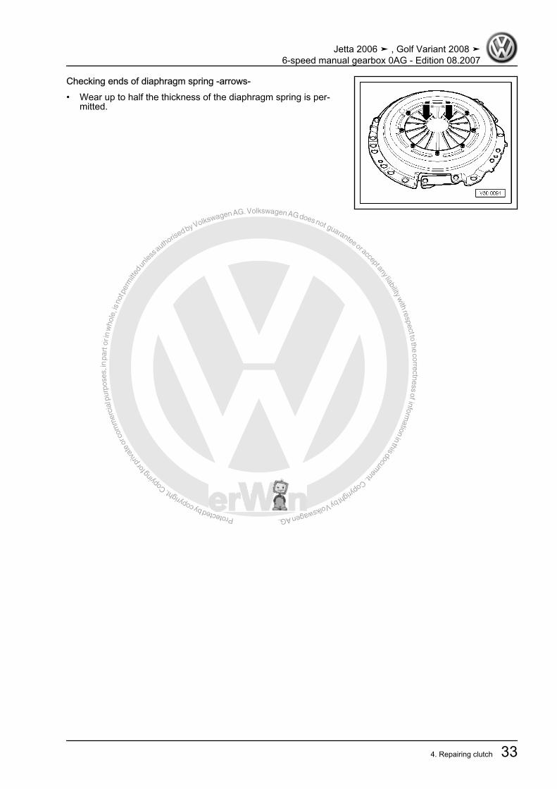
Checking ends of diaphragm spring -arrows-• Wear up to half the thickness of the diaphragm spring is per‐
mitted.
Jetta 2006 ➤ , Golf Variant 2008 ➤6-speed manual gearbox 0AG - Edition 08.2007
4. Repairing clutch 33
Protected by copyright. C
opying
for p
rivat
e or
com
mer
cial
pur
pose
s, in
par
t or i
n w
hole
, is
not p
erm
itted
unles
s authorise
d by Volkswagen AG. Volkswagen AG does not guarantee or accept any liability with respect to the correctness ofinform
ation in this document.Copyright by Volkswagen AG.
34 – Controls, housing1 Fault finding, power transmission– Refer to ⇒ Fault finding, power transmission; Rep. Gr. 30 ;
Complaints about clutch and clutch mechanism and ⇒ Faultfinding, power transmission; Rep. Gr. 34 ; Complaints aboutselector mechanism
Jetta 2006 ➤ , Golf Variant 2008 ➤6-speed manual gearbox 0AG - Edition 08.2007
34 Rep. Gr.34 - Controls, housing
Protected by copyright. C
opying
for p
rivat
e or
com
mer
cial
pur
pose
s, in
par
t or i
n w
hole
, is
not p
erm
itted
unles
s authorise
d by Volkswagen AG. Volkswagen AG does not guarantee or accept any liability with respect to the correctness ofinform
ation in this document.Copyright by Volkswagen AG.
2 Repairing selector mechanism
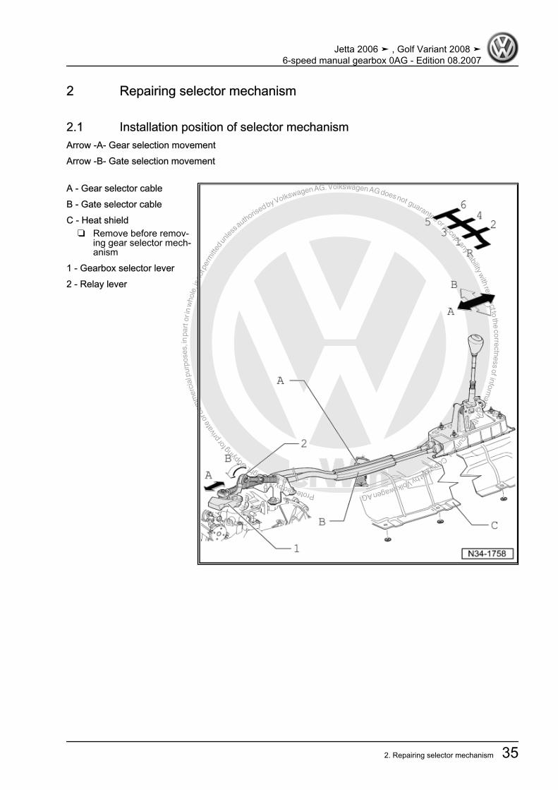
2.1 Installation position of selector mechanismArrow -A- Gear selection movementArrow -B- Gate selection movement
A - Gear selector cableB - Gate selector cableC - Heat shield
❑ Remove before remov‐ing gear selector mech‐anism
1 - Gearbox selector lever2 - Relay lever
Jetta 2006 ➤ , Golf Variant 2008 ➤6-speed manual gearbox 0AG - Edition 08.2007
2. Repairing selector mechanism 35
Protected by copyright. C
opying
for p
rivat
e or
com
mer
cial
pur
pose
s, in
par
t or i
n w
hole
, is
not p
erm
itted
unles
s authorise
d by Volkswagen AG. Volkswagen AG does not guarantee or accept any liability with respect to the correctness ofinform
ation in this document.Copyright by Volkswagen AG.
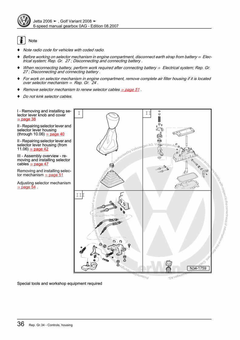
Note
♦ Note radio code for vehicles with coded radio.♦ Before working on selector mechanism in engine compartment, disconnect earth strap from battery ⇒ Elec‐
trical system; Rep. Gr. 27 ; Disconnecting and connecting battery .♦ When reconnecting battery, perform work required after connecting battery ⇒ Electrical system; Rep. Gr.
27 ; Disconnecting and connecting battery .♦ For work on selector mechanism in engine compartment, remove complete air filter housing if it is located
over selector mechanism ⇒ Rep. Gr. 24 .♦ Remove selector mechanism to renew selector cables ⇒ page 51 .♦ Do not kink selector cables.
I - Removing and installing se‐lector lever knob and cover⇒ page 38II - Repairing selector lever andselector lever housing(through 10.06) ⇒ page 40II - Repairing selector lever andselector lever housing (from11.06) ⇒ page 42III - Assembly overview - re‐moving and installing selectorcables ⇒ page 47Removing and installing selec‐tor mechanism ⇒ page 51
Adjusting selector mechanism⇒ page 54 .
Special tools and workshop equipment required
Jetta 2006 ➤ , Golf Variant 2008 ➤6-speed manual gearbox 0AG - Edition 08.2007
36 Rep. Gr.34 - Controls, housing

Protected by copyright. C
opying
for p
rivat
e or
com
mer
cial
pur
pose
s, in
par
t or i
n w
hole
, is
not p
erm
itted
unles
s authorise
d by Volkswagen AG. Volkswagen AG does not guarantee or accept any liability with respect to the correctness ofinform
ation in this document.Copyright by Volkswagen AG.
♦ Hose clip pliers -V.A.G 1275-
♦ Torque wrench -V.A.G 1331-
Jetta 2006 ➤ , Golf Variant 2008 ➤6-speed manual gearbox 0AG - Edition 08.2007
2. Repairing selector mechanism 37
Protected by copyright. C
opying
for p
rivat
e or
com
mer
cial
pur
pose
s, in
par
t or i
n w
hole
, is
not p
erm
itted
unles
s authorise
d by Volkswagen AG. Volkswagen AG does not guarantee or accept any liability with respect to the correctness ofinform
ation in this document.Copyright by Volkswagen AG.
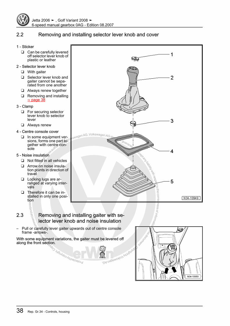
2.2 Removing and installing selector lever knob and cover
1 - Sticker❑ Can be carefully levered
off selector lever knob ofplastic or leather
2 - Selector lever knob❑ With gaiter❑ Selector lever knob and
gaiter cannot be sepa‐rated from one another
❑ Always renew together❑ Removing and installing
⇒ page 383 - Clamp
❑ For securing selectorlever knob to selectorlever
❑ Always renew4 - Centre console cover
❑ In some equipment ver‐sions, forms one part to‐gether with centre con‐sole
5 - Noise insulation❑ Not fitted in all vehicles❑ Arrow on noise insula‐
tion points in direction oftravel
❑ Locking lugs are ar‐ranged at varying inter‐vals
❑ Therefore it can be in‐stalled in only one posi‐tion
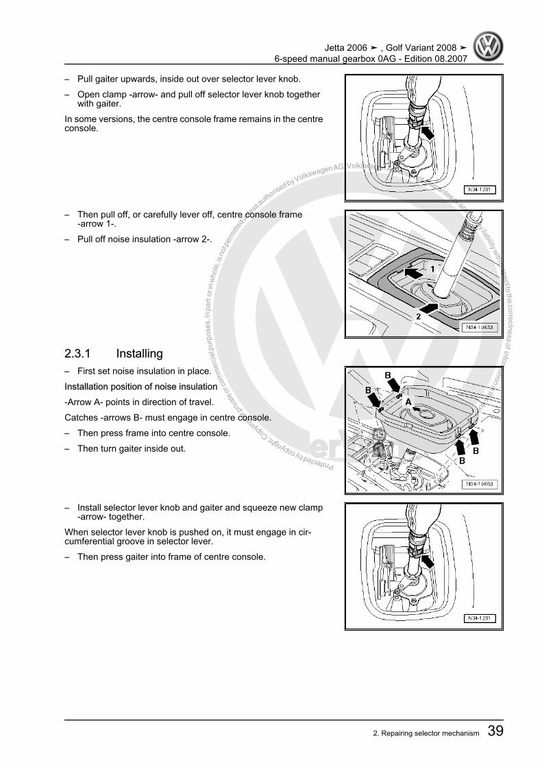
2.3 Removing and installing gaiter with se‐lector lever knob and noise insulation
– Pull or carefully lever gaiter upwards out of centre consoleframe -arrows-.
With some equipment variations, the gaiter must be levered offalong the front section.
Jetta 2006 ➤ , Golf Variant 2008 ➤6-speed manual gearbox 0AG - Edition 08.2007
38 Rep. Gr.34 - Controls, housing
Protected by copyright. C
opying
for p
rivat
e or
com
mer
cial
pur
pose
s, in
par
t or i
n w
hole
, is
not p
erm
itted
unles
s authorise
d by Volkswagen AG. Volkswagen AG does not guarantee or accept any liability with respect to the correctness ofinform
ation in this document.Copyright by Volkswagen AG.
– Pull gaiter upwards, inside out over selector lever knob.– Open clamp -arrow- and pull off selector lever knob together
with gaiter.In some versions, the centre console frame remains in the centreconsole.
– Then pull off, or carefully lever off, centre console frame-arrow 1-.
– Pull off noise insulation -arrow 2-.
2.3.1 Installing– First set noise insulation in place.Installation position of noise insulation-Arrow A- points in direction of travel.Catches -arrows B- must engage in centre console.– Then press frame into centre console.– Then turn gaiter inside out.
– Install selector lever knob and gaiter and squeeze new clamp-arrow- together.
When selector lever knob is pushed on, it must engage in cir‐cumferential groove in selector lever.– Then press gaiter into frame of centre console.
Jetta 2006 ➤ , Golf Variant 2008 ➤6-speed manual gearbox 0AG - Edition 08.2007
2. Repairing selector mechanism 39

Protected by copyright. C
opying
for p
rivat
e or
com
mer
cial
pur
pose
s, in
par
t or i
n w
hole
, is
not p
erm
itted
unles
s authorise
d by Volkswagen AG. Volkswagen AG does not guarantee or accept any liability with respect to the correctness ofinform
ation in this document.Copyright by Volkswagen AG.
2.4 Repairing selector lever and selector lever housing (through 10.06)
Note
Lubricate bearing positions and sliding surfaces with grease -G 000 450 02- .
1 - Securing clip❑ Removing and installing
⇒ page 412 - Bush3 - Compression spring4 - Bush5 - Torx screw, 5 Nm6 - Cover7 - Damping8 - Damping9 - Ball socket10 - Selector lever guide11 - Damping washer12 - Seal
❑ Between selector leverhousing and underbody
❑ Self-adhesive❑ Bond to selector lever
housing13 - Selector lever14 - Selector lever housing15 - Bearing bush16 - Pivot pin17 - Guide bush18 - Compression spring
❑ Installing ⇒ page 4119 - Gate selector lever20 - Torx screw, 5 Nm21 - Seal
❑ Always renew22 - Base plate
❑ Bend open tabs to remove❑ Always renew
23 - Gate selector cable❑ On gate selector lever❑ Removing and installing ⇒ page 41
24 - Gear selector cable❑ Removing from and attaching to selector lever guide ⇒ page 41
Jetta 2006 ➤ , Golf Variant 2008 ➤6-speed manual gearbox 0AG - Edition 08.2007
40 Rep. Gr.34 - Controls, housing
Protected by copyright. C
opying
for p
rivat
e or
com
mer
cial
pur
pose
s, in
par
t or i
n w
hole
, is
not p
erm
itted
unles
s authorise
d by Volkswagen AG. Volkswagen AG does not guarantee or accept any liability with respect to the correctness ofinform
ation in this document.Copyright by Volkswagen AG.
25 - Securing clip❑ Always renew
26 - Hexagon nut M8, 25 Nm, hexagon nut M6, 8 Nm❑ Qty. 4
27 - Bearing bush❑ Fits in one position only
28 - Securing clip❑ Always renew
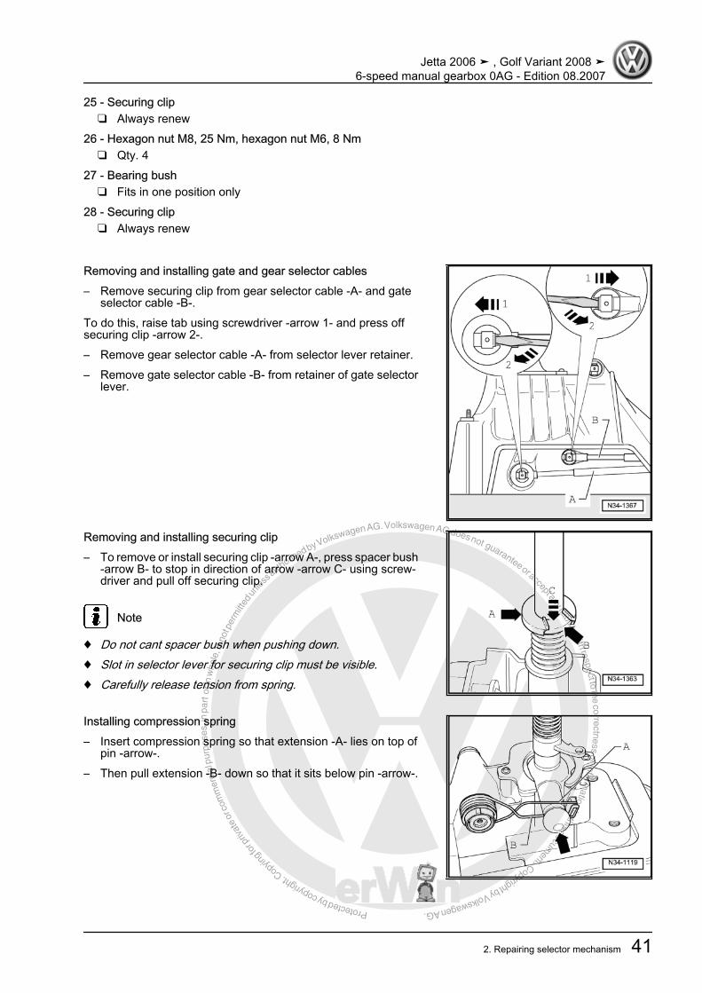
Removing and installing gate and gear selector cables– Remove securing clip from gear selector cable -A- and gate
selector cable -B-.To do this, raise tab using screwdriver -arrow 1- and press offsecuring clip -arrow 2-.– Remove gear selector cable -A- from selector lever retainer.– Remove gate selector cable -B- from retainer of gate selector
lever.
Removing and installing securing clip– To remove or install securing clip -arrow A-, press spacer bush
-arrow B- to stop in direction of arrow -arrow C- using screw‐driver and pull off securing clip.
Note
♦ Do not cant spacer bush when pushing down.♦ Slot in selector lever for securing clip must be visible.♦ Carefully release tension from spring.
Installing compression spring– Insert compression spring so that extension -A- lies on top of
pin -arrow-.– Then pull extension -B- down so that it sits below pin -arrow-.
Jetta 2006 ➤ , Golf Variant 2008 ➤6-speed manual gearbox 0AG - Edition 08.2007
2. Repairing selector mechanism 41
Protected by copyright. C
opying
for p
rivat
e or
com
mer
cial
pur
pose
s, in
par
t or i
n w
hole
, is
not p
erm
itted
unles
s authorise
d by Volkswagen AG. Volkswagen AG does not guarantee or accept any liability with respect to the correctness ofinform
ation in this document.Copyright by Volkswagen AG.
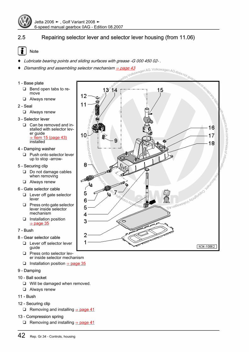
2.5 Repairing selector lever and selector lever housing (from 11.06)
Note
♦ Lubricate bearing points and sliding surfaces with grease -G 000 450 02- .♦ Dismantling and assembling selector mechanism ⇒ page 43
1 - Base plate❑ Bend open tabs to re‐
move❑ Always renew
2 - Seal❑ Always renew
3 - Selector lever❑ Can be removed and in‐
stalled with selector lev‐er guide⇒ Item 15 (page 43)installed
4 - Damping washer❑ Push onto selector lever
up to stop -arrow-5 - Securing clip
❑ Do not damage cableswhen removing
❑ Always renew6 - Gate selector cable
❑ Lever off gate selectorlever
❑ Press onto gate selectorlever inside selectormechanism
❑ Installation position⇒ page 35
7 - Bush8 - Gear selector cable
❑ Lever off selector leverguide
❑ Press onto selector lev‐er inside selector mechanism
❑ Installation position ⇒ page 359 - Damping10 - Ball socket
❑ Will be damaged when removed.❑ Always renew
11 - Bush12 - Securing clip
❑ Removing and installing ⇒ page 4113 - Compression spring
❑ Removing and installing ⇒ page 41
Jetta 2006 ➤ , Golf Variant 2008 ➤6-speed manual gearbox 0AG - Edition 08.2007
42 Rep. Gr.34 - Controls, housing
Protected by copyright. C
opying
for p
rivat
e or
com
mer
cial
pur
pose
s, in
par
t or i
n w
hole
, is
not p
erm
itted
unles
s authorise
d by Volkswagen AG. Volkswagen AG does not guarantee or accept any liability with respect to the correctness ofinform
ation in this document.Copyright by Volkswagen AG.
14 - Bush15 - Selector lever guide16 - Hexagon nut M8 25 Nm; hexagon nut M6 8 Nm
❑ Qty. 417 - Seal
❑ Between selector lever housing and underbody❑ Self-adhesive❑ Bond to selector lever housing
18 - Selector lever housing❑ With compression spring and gate selector lever❑ Compression spring and gate selector lever cannot be removed
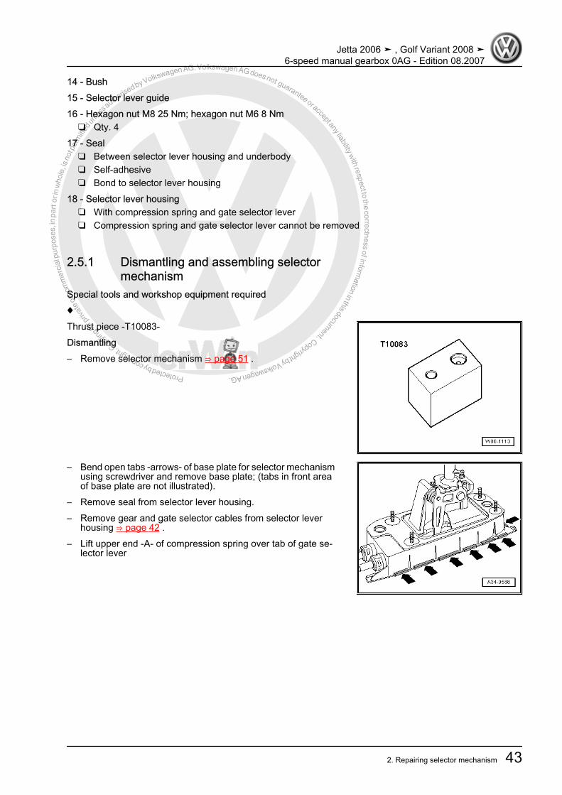
2.5.1 Dismantling and assembling selectormechanism
Special tools and workshop equipment required♦Thrust piece -T10083-Dismantling– Remove selector mechanism ⇒ page 51 .
– Bend open tabs -arrows- of base plate for selector mechanismusing screwdriver and remove base plate; (tabs in front areaof base plate are not illustrated).
– Remove seal from selector lever housing.– Remove gear and gate selector cables from selector lever
housing ⇒ page 42 .– Lift upper end -A- of compression spring over tab of gate se‐
lector lever
Jetta 2006 ➤ , Golf Variant 2008 ➤6-speed manual gearbox 0AG - Edition 08.2007
2. Repairing selector mechanism 43
Protected by copyright. C
opying
for p
rivat
e or
com
mer
cial
pur
pose
s, in
par
t or i
n w
hole
, is
not p
erm
itted
unles
s authorise
d by Volkswagen AG. Volkswagen AG does not guarantee or accept any liability with respect to the correctness ofinform
ation in this document.Copyright by Volkswagen AG.
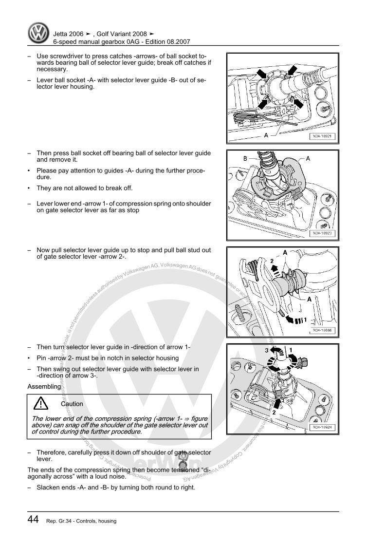
– Use screwdriver to press catches -arrows- of ball socket to‐wards bearing ball of selector lever guide; break off catches ifnecessary.
– Lever ball socket -A- with selector lever guide -B- out of se‐lector lever housing.
– Then press ball socket off bearing ball of selector lever guideand remove it.
• Please pay attention to guides -A- during the further proce‐dure.
• They are not allowed to break off.
– Lever lower end -arrow 1- of compression spring onto shoulderon gate selector lever as far as stop
– Now pull selector lever guide up to stop and pull ball stud outof gate selector lever -arrow 2-.
– Then turn selector lever guide in -direction of arrow 1-• Pin -arrow 2- must be in notch in selector housing– Then swing out selector lever guide with selector lever in
-direction of arrow 3-.Assembling
Caution
The lower end of the compression spring (-arrow 1- ⇒ figureabove) can snap off the shoulder of the gate selector lever outof control during the further procedure.
– Therefore, carefully press it down off shoulder of gate selectorlever.
The ends of the compression spring then become tensioned “di‐agonally across” with a loud noise.– Slacken ends -A- and -B- by turning both round to right.
Jetta 2006 ➤ , Golf Variant 2008 ➤6-speed manual gearbox 0AG - Edition 08.2007
44 Rep. Gr.34 - Controls, housing
Protected by copyright. C
opying
for p
rivat
e or
com
mer
cial
pur
pose
s, in
par
t or i
n w
hole
, is
not p
erm
itted
unles
s authorise
d by Volkswagen AG. Volkswagen AG does not guarantee or accept any liability with respect to the correctness ofinform
ation in this document.Copyright by Volkswagen AG.
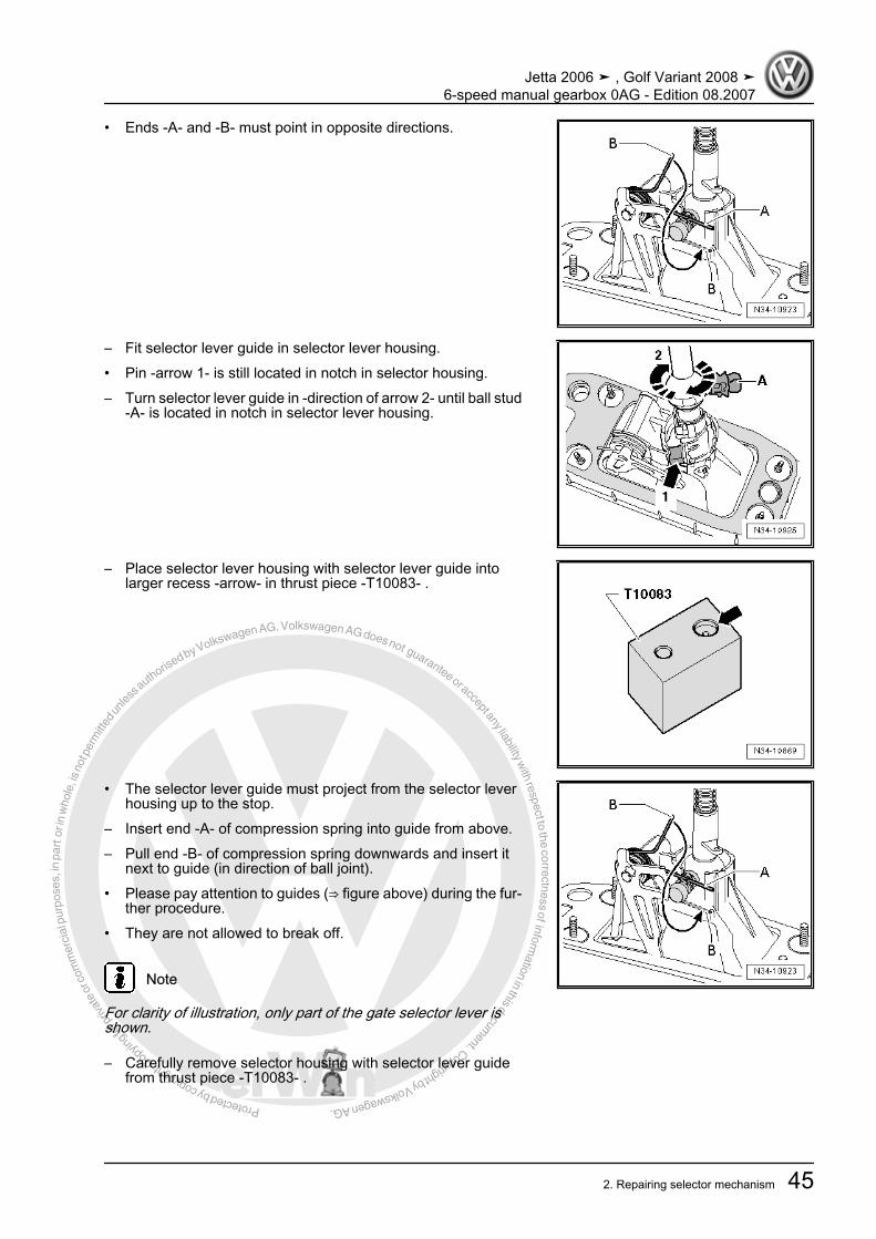
• Ends -A- and -B- must point in opposite directions.
– Fit selector lever guide in selector lever housing.• Pin -arrow 1- is still located in notch in selector housing.– Turn selector lever guide in -direction of arrow 2- until ball stud
-A- is located in notch in selector lever housing.
– Place selector lever housing with selector lever guide intolarger recess -arrow- in thrust piece -T10083- .
• The selector lever guide must project from the selector leverhousing up to the stop.
– Insert end -A- of compression spring into guide from above.– Pull end -B- of compression spring downwards and insert it
next to guide (in direction of ball joint).• Please pay attention to guides (⇒ figure above) during the fur‐
ther procedure.• They are not allowed to break off.
Note
For clarity of illustration, only part of the gate selector lever isshown.
– Carefully remove selector housing with selector lever guidefrom thrust piece -T10083- .
Jetta 2006 ➤ , Golf Variant 2008 ➤6-speed manual gearbox 0AG - Edition 08.2007
2. Repairing selector mechanism 45

Protected by copyright. C
opying
for p
rivat
e or
com
mer
cial
pur
pose
s, in
par
t or i
n w
hole
, is
not p
erm
itted
unles
s authorise
d by Volkswagen AG. Volkswagen AG does not guarantee or accept any liability with respect to the correctness ofinform
ation in this document.Copyright by Volkswagen AG.
– Move gate selector lever back to stop (opposite from mountingholes for gear and gate selector cable) -arrow 1-.
– Grease ball stud.– Press ball stud into gate selector lever -arrow 2-.• Guides -A- and tabs -B- are not allowed to be damaged.
– Place selector lever housing with selector lever guide intolarger recess -arrow- in thrust piece -T10083- .
• The selector lever guide must project from the selector leverhousing up to the stop.
– Lift upper end -A- of compression spring over pin of gate se‐lector lever
• Use a new ball socket -B-.– Grease ball socket and bearing ball of selector lever guide.– Press ball socket onto bearing ball of selector lever guide up
to stop.– Remove selector lever housing from thrust piece -T10083- .– Insert lower end -C- of compression spring into guide.– Lift upper end -A- of compression spring over pin of gate se‐
lector lever into guide.– Press ball socket into selector lever housing -arrows-.• All locking lugs must clip in.– Mount selector lever, gear selector cable, gate selector cable
and base plate ⇒ page 42– Install selector mechanism ⇒ page 51 .
Jetta 2006 ➤ , Golf Variant 2008 ➤6-speed manual gearbox 0AG - Edition 08.2007
46 Rep. Gr.34 - Controls, housing

Protected by copyright. C
opying
for p
rivat
e or
com
mer
cial
pur
pose
s, in
par
t or i
n w
hole
, is
not p
erm
itted
unles
s authorise
d by Volkswagen AG. Volkswagen AG does not guarantee or accept any liability with respect to the correctness ofinform
ation in this document.Copyright by Volkswagen AG.
2.6 Assembly overview - removing and installing selector cables
Note
Lubricate bearing positions and sliding surfaces with grease -G 000 450 02- .
1 - Gear selector cable❑ Connect to cable end-
piece⇒ Item 11 (page 48)
❑ Installation position⇒ page 35
❑ From 11.06, modifiedattachment to selectorlever inside selectormechanism⇒ Item 8 (page 42)
2 - Gate selector cable❑ Connect to cable end-
piece⇒ Item 10 (page 47)
❑ Installation position⇒ page 35
❑ From 11.06, modifiedattachment to gate se‐lector lever inside selec‐tor mechanism⇒ Item 6 (page 42)
3 - Securing clip❑ Always renew
4 - Selector lever housing5 - Securing clip
❑ Always renew❑ Do not damage cables
when removing6 - Hexagon bolt, 20 Nm
❑ Qty. 3❑ For support bracket
7 - Support bracket❑ May be made from plastic or metal
8 - Grommet❑ Support bracket mounting on gearbox
9 - Spacer10 - Cable end-piece
❑ After installing, adjust selector mechanism ⇒ page 54❑ For gate selector cable to relay lever❑ Do not interchange; cable end-pieces for gate selector cable to relay lever and gear selector cable to
gearbox selector lever are different❑ For metal relay lever, secured with securing clip ⇒ Item 12 (page 48)❑ From 05.07, fitted in conjunction with plastic relay lever ⇒ page 50❑ Removing from plastic relay lever ⇒ page 50❑ Pressing onto plastic relay lever ⇒ page 50
Jetta 2006 ➤ , Golf Variant 2008 ➤6-speed manual gearbox 0AG - Edition 08.2007
2. Repairing selector mechanism 47
Protected by copyright. C
opying
for p
rivat
e or
com
mer
cial
pur
pose
s, in
par
t or i
n w
hole
, is
not p
erm
itted
unles
s authorise
d by Volkswagen AG. Volkswagen AG does not guarantee or accept any liability with respect to the correctness ofinform
ation in this document.Copyright by Volkswagen AG.
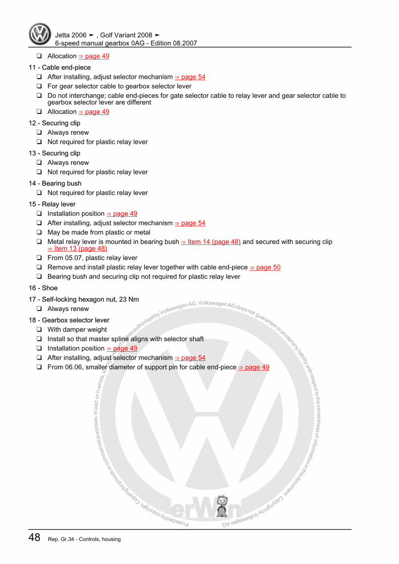
❑ Allocation ⇒ page 4911 - Cable end-piece
❑ After installing, adjust selector mechanism ⇒ page 54❑ For gear selector cable to gearbox selector lever❑ Do not interchange; cable end-pieces for gate selector cable to relay lever and gear selector cable to
gearbox selector lever are different❑ Allocation ⇒ page 49
12 - Securing clip❑ Always renew❑ Not required for plastic relay lever
13 - Securing clip❑ Always renew❑ Not required for plastic relay lever
14 - Bearing bush❑ Not required for plastic relay lever
15 - Relay lever❑ Installation position ⇒ page 49❑ After installing, adjust selector mechanism ⇒ page 54❑ May be made from plastic or metal❑ Metal relay lever is mounted in bearing bush ⇒ Item 14 (page 48) and secured with securing clip
⇒ Item 13 (page 48)❑ From 05.07, plastic relay lever❑ Remove and install plastic relay lever together with cable end-piece ⇒ page 50❑ Bearing bush and securing clip not required for plastic relay lever
16 - Shoe17 - Self-locking hexagon nut, 23 Nm
❑ Always renew18 - Gearbox selector lever
❑ With damper weight❑ Install so that master spline aligns with selector shaft❑ Installation position ⇒ page 49❑ After installing, adjust selector mechanism ⇒ page 54❑ From 06.06, smaller diameter of support pin for cable end-piece ⇒ page 49
Jetta 2006 ➤ , Golf Variant 2008 ➤6-speed manual gearbox 0AG - Edition 08.2007
48 Rep. Gr.34 - Controls, housing

Protected by copyright. C
opying
for p
rivat
e or
com
mer
cial
pur
pose
s, in
par
t or i
n w
hole
, is
not p
erm
itted
unles
s authorise
d by Volkswagen AG. Volkswagen AG does not guarantee or accept any liability with respect to the correctness ofinform
ation in this document.Copyright by Volkswagen AG.
Allocation of cable end-piecesThe holes in the cable end-pieces have different diameters.
Cable end-piece for Dimension “a”1 - Gear selector cable to gearbox selector leverfrom 06.06
8.5 mm
2 - Gear selector cable to gearbox selector leverthrough 05.06
10 mm
2 - Gate selector cable to metal relay lever 8 mm2 - Gate selector cable to plastic relay lever⇒ page 50
10 mm
From 06.06, smaller diameter of support pin for gear selector ca‐ble end-piece
Support pin for gear selector cable end-piece Dimension “a”Through 05.06 10 mmFrom 06.06 8.5 mm
Installation position of gearbox selector lever and relay lever1 - Gearbox selector lever with damper weight2 - Relay lever engages in guide rail of gearbox selector lever viashoe -arrow-.
Jetta 2006 ➤ , Golf Variant 2008 ➤6-speed manual gearbox 0AG - Edition 08.2007
2. Repairing selector mechanism 49

Protected by copyright. C
opying
for p
rivat
e or
com
mer
cial
pur
pose
s, in
par
t or i
n w
hole
, is
not p
erm
itted
unles
s authorise
d by Volkswagen AG. Volkswagen AG does not guarantee or accept any liability with respect to the correctness ofinform
ation in this document.Copyright by Volkswagen AG.
2.7 Plastic relay leverFrom 05.07, plastic relay lever• To remove relay lever, first separate cable end-piece from
gate selector lever:
This will avoid damage to the gate selector cable– Pull locking mechanism forward to stop in
-direction of arrow 1- and then lock by turning to left in-direction of arrow 2-.
– Then push relay lever forwards (-in direction of arrow 3-).– Press latch -arrow 1- (⇒ previous figure) down to stop and re‐
move relay lever together with cable end-piece.• The cable end-piece can be removed only with the relay lever
removed ⇒ page 51 .
Note
To fit, lubricate bearing points and sliding surfaces with grease -G 000 450 02- .
– Press cable end-piece onto relay lever ⇒ page 51 .– Insert relay lever together with cable end-piece.• Fastener -arrow 1- secures relay lever (⇒ previous figure).• Cable end-piece must be located behind fastener -arrow 2- (⇒
previous figure).
Jetta 2006 ➤ , Golf Variant 2008 ➤6-speed manual gearbox 0AG - Edition 08.2007
50 Rep. Gr.34 - Controls, housing
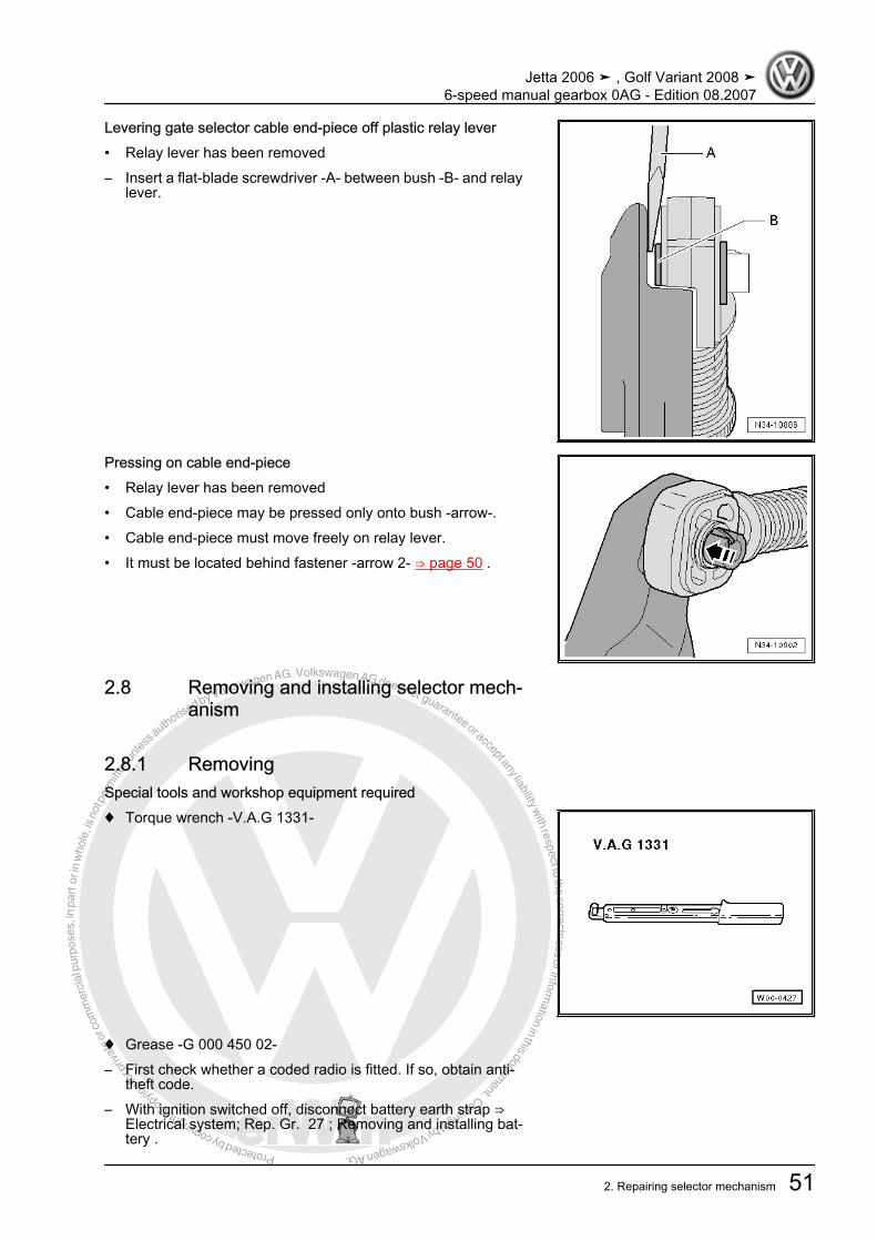
Protected by copyright. C
opying
for p
rivat
e or
com
mer
cial
pur
pose
s, in
par
t or i
n w
hole
, is
not p
erm
itted
unles
s authorise
d by Volkswagen AG. Volkswagen AG does not guarantee or accept any liability with respect to the correctness ofinform
ation in this document.Copyright by Volkswagen AG.
Levering gate selector cable end-piece off plastic relay lever• Relay lever has been removed– Insert a flat-blade screwdriver -A- between bush -B- and relay
lever.
Pressing on cable end-piece• Relay lever has been removed• Cable end-piece may be pressed only onto bush -arrow-.• Cable end-piece must move freely on relay lever.• It must be located behind fastener -arrow 2- ⇒ page 50 .
2.8 Removing and installing selector mech‐anism
2.8.1 RemovingSpecial tools and workshop equipment required♦ Torque wrench -V.A.G 1331-
♦ Grease -G 000 450 02-– First check whether a coded radio is fitted. If so, obtain anti-
theft code.– With ignition switched off, disconnect battery earth strap ⇒
Electrical system; Rep. Gr. 27 ; Removing and installing bat‐tery .
Jetta 2006 ➤ , Golf Variant 2008 ➤6-speed manual gearbox 0AG - Edition 08.2007
2. Repairing selector mechanism 51
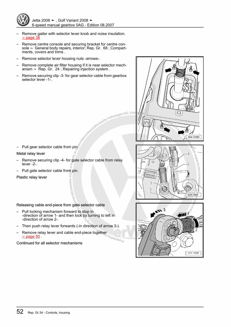
Protected by copyright. C
opying
for p
rivat
e or
com
mer
cial
pur
pose
s, in
par
t or i
n w
hole
, is
not p
erm
itted
unles
s authorise
d by Volkswagen AG. Volkswagen AG does not guarantee or accept any liability with respect to the correctness ofinform
ation in this document.Copyright by Volkswagen AG.
– Remove gaiter with selector lever knob and noise insulation.⇒ page 38
– Remove centre console and securing bracket for centre con‐sole ⇒ General body repairs, interior; Rep. Gr. 68 ; Compart‐ments, covers and trims .
– Remove selector lever housing nuts -arrows-.– Remove complete air filter housing if it is near selector mech‐
anism ⇒ Rep. Gr. 24 ; Repairing injection system .– Remove securing clip -3- for gear selector cable from gearbox
selector lever -1-.
– Pull gear selector cable from pin.Metal relay lever– Remove securing clip -4- for gate selector cable from relay
lever -2-.– Pull gate selector cable from pin.Plastic relay lever
Releasing cable end-piece from gate selector cable– Pull locking mechanism forward to stop in
-direction of arrow 1- and then lock by turning to left in-direction of arrow 2-.
– Then push relay lever forwards (-in direction of arrow 3-).– Remove relay lever and cable end-piece together
⇒ page 50 .Continued for all selector mechanisms
Jetta 2006 ➤ , Golf Variant 2008 ➤6-speed manual gearbox 0AG - Edition 08.2007
52 Rep. Gr.34 - Controls, housing
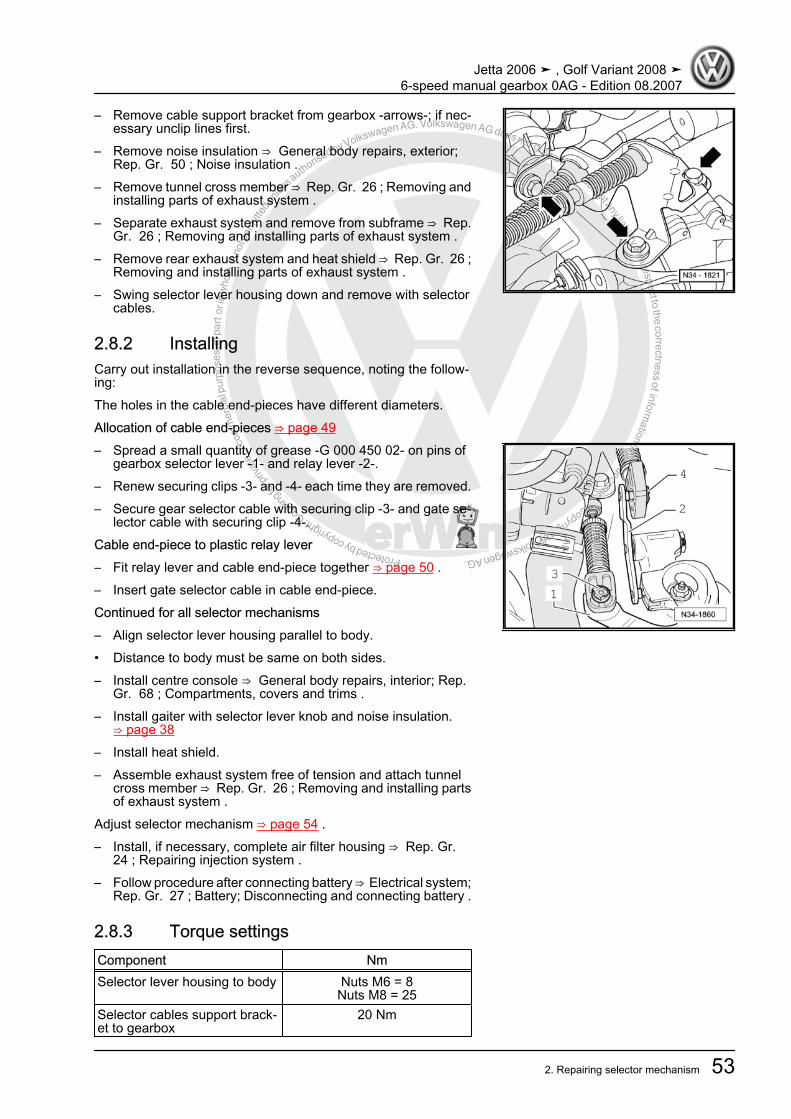
Protected by copyright. C
opying
for p
rivat
e or
com
mer
cial
pur
pose
s, in
par
t or i
n w
hole
, is
not p
erm
itted
unles
s authorise
d by Volkswagen AG. Volkswagen AG does not guarantee or accept any liability with respect to the correctness ofinform
ation in this document.Copyright by Volkswagen AG.
– Remove cable support bracket from gearbox -arrows-; if nec‐essary unclip lines first.
– Remove noise insulation ⇒ General body repairs, exterior;Rep. Gr. 50 ; Noise insulation .
– Remove tunnel cross member ⇒ Rep. Gr. 26 ; Removing andinstalling parts of exhaust system .
– Separate exhaust system and remove from subframe ⇒ Rep.Gr. 26 ; Removing and installing parts of exhaust system .
– Remove rear exhaust system and heat shield ⇒ Rep. Gr. 26 ;Removing and installing parts of exhaust system .
– Swing selector lever housing down and remove with selectorcables.
2.8.2 InstallingCarry out installation in the reverse sequence, noting the follow‐ing:The holes in the cable end-pieces have different diameters.Allocation of cable end-pieces ⇒ page 49– Spread a small quantity of grease -G 000 450 02- on pins of
gearbox selector lever -1- and relay lever -2-.– Renew securing clips -3- and -4- each time they are removed.– Secure gear selector cable with securing clip -3- and gate se‐
lector cable with securing clip -4-.Cable end-piece to plastic relay lever– Fit relay lever and cable end-piece together ⇒ page 50 .– Insert gate selector cable in cable end-piece.Continued for all selector mechanisms– Align selector lever housing parallel to body.• Distance to body must be same on both sides.– Install centre console ⇒ General body repairs, interior; Rep.
Gr. 68 ; Compartments, covers and trims .– Install gaiter with selector lever knob and noise insulation.
⇒ page 38– Install heat shield.– Assemble exhaust system free of tension and attach tunnel
cross member ⇒ Rep. Gr. 26 ; Removing and installing partsof exhaust system .
Adjust selector mechanism ⇒ page 54 .– Install, if necessary, complete air filter housing ⇒ Rep. Gr.
24 ; Repairing injection system .– Follow procedure after connecting battery ⇒ Electrical system;
Rep. Gr. 27 ; Battery; Disconnecting and connecting battery .
2.8.3 Torque settingsComponent NmSelector lever housing to body Nuts M6 = 8
Nuts M8 = 25Selector cables support brack‐et to gearbox
20 Nm
Jetta 2006 ➤ , Golf Variant 2008 ➤6-speed manual gearbox 0AG - Edition 08.2007
2. Repairing selector mechanism 53
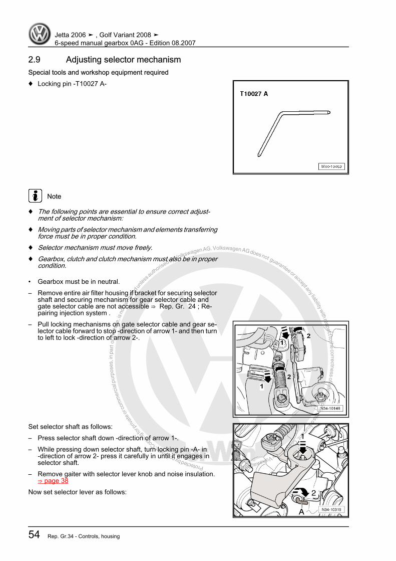
Protected by copyright. C
opying
for p
rivat
e or
com
mer
cial
pur
pose
s, in
par
t or i
n w
hole
, is
not p
erm
itted
unles
s authorise
d by Volkswagen AG. Volkswagen AG does not guarantee or accept any liability with respect to the correctness ofinform
ation in this document.Copyright by Volkswagen AG.
2.9 Adjusting selector mechanismSpecial tools and workshop equipment required♦ Locking pin -T10027 A-
Note
♦ The following points are essential to ensure correct adjust‐ment of selector mechanism:
♦ Moving parts of selector mechanism and elements transferringforce must be in proper condition.
♦ Selector mechanism must move freely.♦ Gearbox, clutch and clutch mechanism must also be in proper
condition.
• Gearbox must be in neutral.– Remove entire air filter housing if bracket for securing selector
shaft and securing mechanism for gear selector cable andgate selector cable are not accessible ⇒ Rep. Gr. 24 ; Re‐pairing injection system .
– Pull locking mechanisms on gate selector cable and gear se‐lector cable forward to stop -direction of arrow 1- and then turnto left to lock -direction of arrow 2-.
Set selector shaft as follows:– Press selector shaft down -direction of arrow 1-.– While pressing down selector shaft, turn locking pin -A- in
-direction of arrow 2- press it carefully in until it engages inselector shaft.
– Remove gaiter with selector lever knob and noise insulation.⇒ page 38
Now set selector lever as follows:
Jetta 2006 ➤ , Golf Variant 2008 ➤6-speed manual gearbox 0AG - Edition 08.2007
54 Rep. Gr.34 - Controls, housing

Protected by copyright. C
opying
for p
rivat
e or
com
mer
cial
pur
pose
s, in
par
t or i
n w
hole
, is
not p
erm
itted
unles
s authorise
d by Volkswagen AG. Volkswagen AG does not guarantee or accept any liability with respect to the correctness ofinform
ation in this document.Copyright by Volkswagen AG.
– Move selector lever to neutral.– Guide locking pin -T10027 A- through hole -A- into hole -B-.
– Check that gate and selector cables -B- are inserted, free ofstress, into locking device -A-.
– Now turn locking mechanisms on gear selector cable and gateselector cable clockwise to stop -direction of arrow 1-.
The spring presses the locking mechanism into original position-direction of arrow 2-.
– Now turn angled rod -A- back to original position-direction of arrow-.
• The angled rod must point straight up.
– Pull locking pin out of holes -A- and -B-.– Install gaiter with selector knob and noise insulation.
⇒ page 38– If removed, install complete air filter housing ⇒ Rep. Gr. 24 ;
Repairing injection system .
2.9.1 Functional check• With gearbox in neutral, selector lever must rest in gate for 3rd
and 4th gear.– Operate clutch.– Select all gears several times. Pay particular attention to op‐
eration of reverse gear lock.
Jetta 2006 ➤ , Golf Variant 2008 ➤6-speed manual gearbox 0AG - Edition 08.2007
2. Repairing selector mechanism 55

Protected by copyright. C
opying
for p
rivat
e or
com
mer
cial
pur
pose
s, in
par
t or i
n w
hole
, is
not p
erm
itted
unles
s authorise
d by Volkswagen AG. Volkswagen AG does not guarantee or accept any liability with respect to the correctness ofinform
ation in this document.Copyright by Volkswagen AG.
– If it continues to be difficult to engage a gear after repeatedattempts, repeat adjustment procedure of selector mechanism⇒ page 54 .
Jetta 2006 ➤ , Golf Variant 2008 ➤6-speed manual gearbox 0AG - Edition 08.2007
56 Rep. Gr.34 - Controls, housing
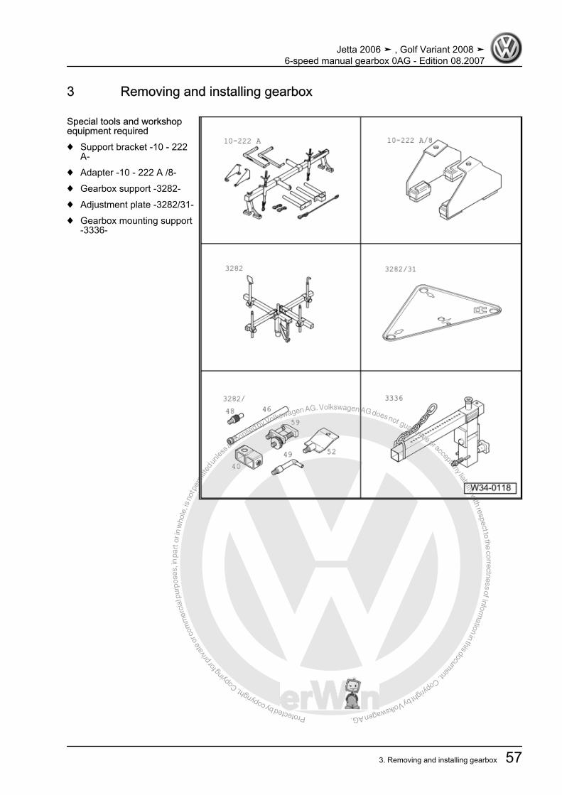
Protected by copyright. C
opying
for p
rivat
e or
com
mer
cial
pur
pose
s, in
par
t or i
n w
hole
, is
not p
erm
itted
unles
s authorise
d by Volkswagen AG. Volkswagen AG does not guarantee or accept any liability with respect to the correctness ofinform
ation in this document.Copyright by Volkswagen AG.
3 Removing and installing gearbox
Special tools and workshopequipment required♦ Support bracket -10 - 222
A-♦ Adapter -10 - 222 A /8-♦ Gearbox support -3282-♦ Adjustment plate -3282/31-♦ Gearbox mounting support
-3336-
Jetta 2006 ➤ , Golf Variant 2008 ➤6-speed manual gearbox 0AG - Edition 08.2007
3. Removing and installing gearbox 57
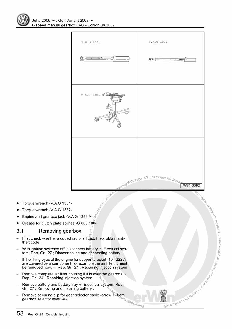
Protected by copyright. C
opying
for p
rivat
e or
com
mer
cial
pur
pose
s, in
par
t or i
n w
hole
, is
not p
erm
itted
unles
s authorise
d by Volkswagen AG. Volkswagen AG does not guarantee or accept any liability with respect to the correctness ofinform
ation in this document.Copyright by Volkswagen AG.
♦ Torque wrench -V.A.G 1331-♦ Torque wrench -V.A.G 1332-♦ Engine and gearbox jack -V.A.G 1383 A-♦ Grease for clutch plate splines -G 000 100-
3.1 Removing gearbox– First check whether a coded radio is fitted. If so, obtain anti-
theft code.– With ignition switched off, disconnect battery ⇒ Electrical sys‐
tem; Rep. Gr. 27 ; Disconnecting and connecting battery .– If the lifting eyes of the engine for support bracket -10 - 222 A-
are covered by a component, for example the air filter, it mustbe removed now. ⇒ Rep. Gr. 24 ; Repairing injection system
– Remove complete air filter housing if it is over the gearbox ⇒ Rep. Gr. 24 ; Repairing injection system .
– Remove battery and battery tray ⇒ Electrical system; Rep.Gr. 27 ; Removing and installing battery .
– Remove securing clip for gear selector cable -arrow 1- fromgearbox selector lever -A-.
Jetta 2006 ➤ , Golf Variant 2008 ➤6-speed manual gearbox 0AG - Edition 08.2007
58 Rep. Gr.34 - Controls, housing

Protected by copyright. C
opying fo
r priv
ate
or co
mm
erci
al p
urpo
ses,
in p
art o
r in
who
le, i
s no
t per
mitt
ed un
less a
uthorised by Volkswagen AG. Volkswagen AG does not guarantee or accept any liability w
ith respect to the correctness ofinformation in this docum
ent.Copyright by Volkswagen AG.
– Pull gear selector cable from pin.Metal relay lever– Remove securing clip -arrow 2- for gate selector cable from
relay lever -B-.– Pull gate selector cable from pin.– Pull securing clip -arrow 3- off relay lever -B- and remove relay
lever.Plastic relay lever
– Release end-piece from gate selector cable ⇒ page 52 .– Press latch -arrow 1- down to stop and remove relay lever to‐
gether with cable end-piece.Continuation for all– Remove gearbox selector lever -A- by removing nut
-arrow 4- (⇒ previous figure).
– Remove cable support bracket from gearbox -arrows-.– Then tie up selector cable and gate cable.
Jetta 2006 ➤ , Golf Variant 2008 ➤6-speed manual gearbox 0AG - Edition 08.2007
3. Removing and installing gearbox 59
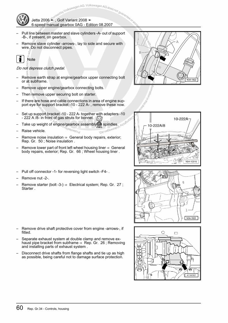
Protected by copyright. C
opying
for p
rivat
e or
com
mer
cial
pur
pose
s, in
par
t or i
n w
hole
, is
not p
erm
itted
unles
s authorise
d by Volkswagen AG. Volkswagen AG does not guarantee or accept any liability with respect to the correctness ofinform
ation in this document.Copyright by Volkswagen AG.
– Pull line between master and slave cylinders -A- out of support-B-, if present, on gearbox.
– Remove slave cylinder -arrows-, lay to side and secure withwire. Do not disconnect pipes.
Note
Do not depress clutch pedal.
– Remove earth strap at engine/gearbox upper connecting boltor at subframe.
– Remove upper engine/gearbox connecting bolts.– Then remove upper securing bolt on starter.– If there are hose and cable connections in area of engine sup‐
port eye for support bracket -10 - 222 A- , remove these now.
– Set up support bracket -10 - 222 A- together with adapters -10- 222 A /8- in front of gas struts for bonnet.
– Take up weight of engine/gearbox assembly on spindles.– Raise vehicle.– Remove noise insulation ⇒ General body repairs, exterior;
Rep. Gr. 50 ; Noise insulation .– Remove lower part of front left wheel housing liner ⇒ General
body repairs, exterior; Rep. Gr. 66 ; Wheel housing liner .
– Pull off connector -1- for reversing light switch -F4- .– Remove nut -2-.– Remove starter (bolt -3-) ⇒ Electrical system; Rep. Gr. 27 ;
Starter .
– Remove drive shaft protective cover from engine -arrows-, iffitted.
– Separate exhaust system at double clamp and remove ex‐haust pipe bracket from subframe ⇒ Rep. Gr. 26 ; Removingand installing parts of exhaust system .
– Disconnect drive shafts from flange shafts and tie up as highas possible, being careful not to damage surface protection.
Jetta 2006 ➤ , Golf Variant 2008 ➤6-speed manual gearbox 0AG - Edition 08.2007
60 Rep. Gr.34 - Controls, housing

Protected by copyright. C
opying
for p
rivat
e or
com
mer
cial
pur
pose
s, in
par
t or i
n w
hole
, is
not p
erm
itted
unles
s authorise
d by Volkswagen AG. Volkswagen AG does not guarantee or accept any liability with respect to the correctness ofinform
ation in this document.Copyright by Volkswagen AG.
– Remove engine/gearbox connecting bolt -A- above rightflange shaft.
– Remove pendulum support -arrows A-, -B- and -C-.
– Remove hexagon bolts -arrows- for left assembly mountingfrom gearbox mounting.
– Tilt engine/gearbox assembly by lowering the left spindle ofsupport bracket -10 - 222 A- .
Note
Be careful of all lines when lowering gearbox.
– Unbolt gearbox support from gearbox -arrows-.To remove gearbox “0AG”, set up gearbox support -3282- withadjustment plate -3282/31- .– Insert gearbox support -3282- in engine and gearbox jack -
V.A.G 1383A- .– Align arms of gearbox support according to holes in adjust‐
ment plate .
Jetta 2006 ➤ , Golf Variant 2008 ➤6-speed manual gearbox 0AG - Edition 08.2007
3. Removing and installing gearbox 61

Protected by copyright. C
opying
for p
rivat
e or
com
mer
cial
pur
pose
s, in
par
t or i
n w
hole
, is
not p
erm
itted
unles
s authorise
d by Volkswagen AG. Volkswagen AG does not guarantee or accept any liability with respect to the correctness ofinform
ation in this document.Copyright by Volkswagen AG.
– Attach support elements -A- to adjustment plate as illustrated.– Position engine and gearbox jack under vehicle. Arrow -B- on
adjustment plate points in direction of vehicle travel.
– Align adjustment plate parallel to gearbox.– Remove engine/gearbox connecting bolt (-arrow- in figure
above).
– Remove engine/gearbox connecting bolts -arrows- in vicinityof sump (bolts on engine remain).
– Press gearbox off dowel sleeves.– Observe intermediate plate on engine.– Have a second mechanic press engine forwards.
– Turn gearbox downwards, in area of differential, and turn rearof gearbox slightly towards front end -arrow 1-.
– At the same time, ensure that engine/gearbox connectingbolts -arrow 2- contact exhaust system.
Jetta 2006 ➤ , Golf Variant 2008 ➤6-speed manual gearbox 0AG - Edition 08.2007
62 Rep. Gr.34 - Controls, housing
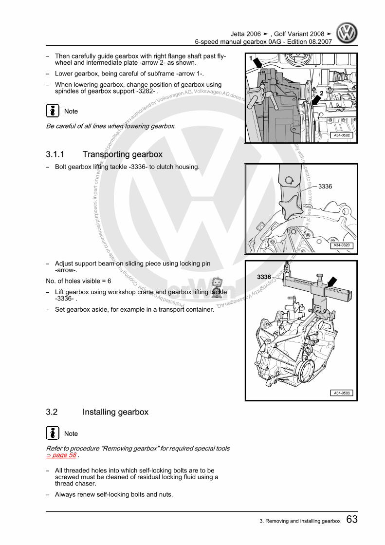
Protected by copyright. C
opying
for p
rivat
e or
com
mer
cial
pur
pose
s, in
par
t or i
n w
hole
, is
not p
erm
itted
unles
s authorise
d by Volkswagen AG. Volkswagen AG does not guarantee or accept any liability with respect to the correctness ofinform
ation in this document.Copyright by Volkswagen AG.
– Then carefully guide gearbox with right flange shaft past fly‐wheel and intermediate plate -arrow 2- as shown.
– Lower gearbox, being careful of subframe -arrow 1-.– When lowering gearbox, change position of gearbox using
spindles of gearbox support -3282- .
Note
Be careful of all lines when lowering gearbox.
3.1.1 Transporting gearbox– Bolt gearbox lifting tackle -3336- to clutch housing.
– Adjust support beam on sliding piece using locking pin-arrow-.
No. of holes visible = 6– Lift gearbox using workshop crane and gearbox lifting tackle
-3336- .– Set gearbox aside, for example in a transport container.
3.2 Installing gearbox
Note
Refer to procedure “Removing gearbox” for required special tools⇒ page 58 .
– All threaded holes into which self-locking bolts are to bescrewed must be cleaned of residual locking fluid using athread chaser.
– Always renew self-locking bolts and nuts.
Jetta 2006 ➤ , Golf Variant 2008 ➤6-speed manual gearbox 0AG - Edition 08.2007
3. Removing and installing gearbox 63
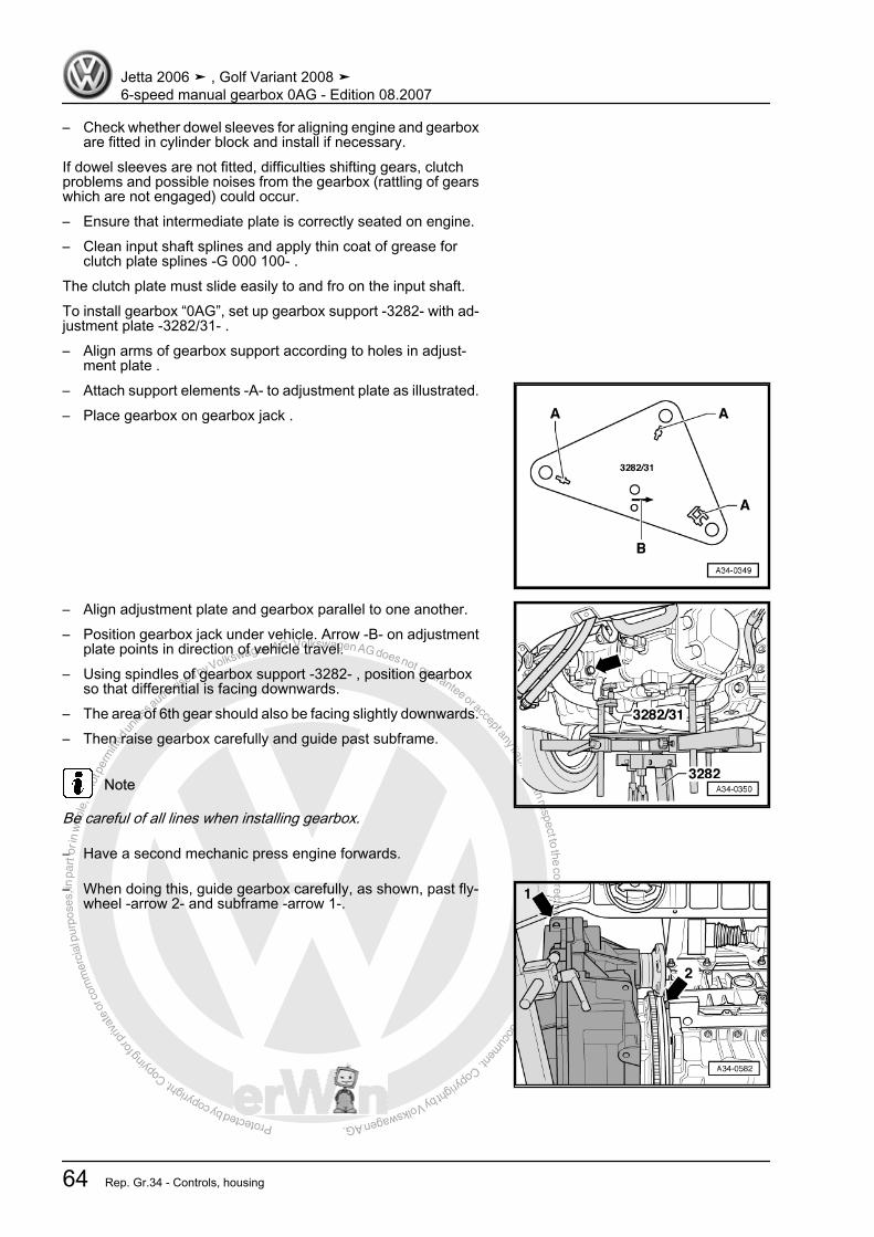
Protected by copyright. C
opying
for p
rivat
e or
com
mer
cial
pur
pose
s, in
par
t or i
n w
hole
, is
not p
erm
itted
unles
s authorise
d by Volkswagen AG. Volkswagen AG does not guarantee or accept any liability with respect to the correctness ofinform
ation in this document.Copyright by Volkswagen AG.
– Check whether dowel sleeves for aligning engine and gearboxare fitted in cylinder block and install if necessary.
If dowel sleeves are not fitted, difficulties shifting gears, clutchproblems and possible noises from the gearbox (rattling of gearswhich are not engaged) could occur.– Ensure that intermediate plate is correctly seated on engine.– Clean input shaft splines and apply thin coat of grease for
clutch plate splines -G 000 100- .The clutch plate must slide easily to and fro on the input shaft.To install gearbox “0AG”, set up gearbox support -3282- with ad‐justment plate -3282/31- .– Align arms of gearbox support according to holes in adjust‐
ment plate .– Attach support elements -A- to adjustment plate as illustrated.– Place gearbox on gearbox jack .
– Align adjustment plate and gearbox parallel to one another.– Position gearbox jack under vehicle. Arrow -B- on adjustment
plate points in direction of vehicle travel.– Using spindles of gearbox support -3282- , position gearbox
so that differential is facing downwards.– The area of 6th gear should also be facing slightly downwards.– Then raise gearbox carefully and guide past subframe.
Note
Be careful of all lines when installing gearbox.
– Have a second mechanic press engine forwards.
– When doing this, guide gearbox carefully, as shown, past fly‐wheel -arrow 2- and subframe -arrow 1-.
Jetta 2006 ➤ , Golf Variant 2008 ➤6-speed manual gearbox 0AG - Edition 08.2007
64 Rep. Gr.34 - Controls, housing
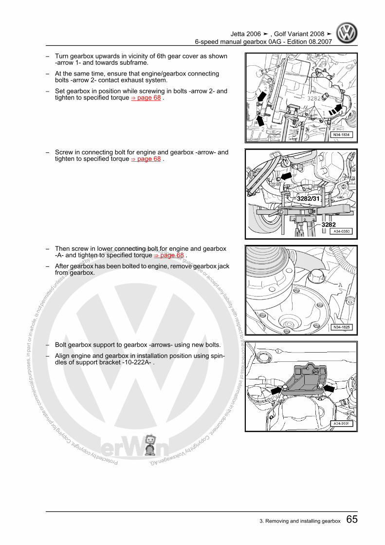
Protected by copyright. C
opying
for p
rivat
e or
com
mer
cial
pur
pose
s, in
par
t or i
n w
hole
, is
not p
erm
itted
unles
s authorise
d by Volkswagen AG. Volkswagen AG does not guarantee or accept any liability with respect to the correctness ofinform
ation in this document.Copyright by Volkswagen AG.
– Turn gearbox upwards in vicinity of 6th gear cover as shown-arrow 1- and towards subframe.
– At the same time, ensure that engine/gearbox connectingbolts -arrow 2- contact exhaust system.
– Set gearbox in position while screwing in bolts -arrow 2- andtighten to specified torque ⇒ page 68 .
– Screw in connecting bolt for engine and gearbox -arrow- andtighten to specified torque ⇒ page 68 .
– Then screw in lower connecting bolt for engine and gearbox-A- and tighten to specified torque ⇒ page 68 .
– After gearbox has been bolted to engine, remove gearbox jackfrom gearbox.
– Bolt gearbox support to gearbox -arrows- using new bolts.– Align engine and gearbox in installation position using spin‐
dles of support bracket -10-222A- .
Jetta 2006 ➤ , Golf Variant 2008 ➤6-speed manual gearbox 0AG - Edition 08.2007
3. Removing and installing gearbox 65

Protected by copyright. C
opying
for p
rivat
e or
com
mer
cial
pur
pose
s, in
par
t or i
n w
hole
, is
not p
erm
itted
unles
s authorise
d by Volkswagen AG. Volkswagen AG does not guarantee or accept any liability with respect to the correctness ofinform
ation in this document.Copyright by Volkswagen AG.
– Install left assembly mounting using new hexagon bolts-arrows- and tighten to specified torque ⇒ page 68 .
WARNING
Do not remove support bracket -10 - 222 A- until the bolts se‐curing the left and right assembly mountings have been tight‐ened to specified torque.
– Insert upper engine/gearbox securing bolts and tighten to tor‐que specification ⇒ page 68 .
– Install pendulum support -arrows A-, -B- and -C- ⇒ Runninggear, axles, steering; Rep. Gr. 40 ; Assembly overview - sub‐frame, anti-roll bar, suspension links .
– Use new bolts for securing.
Note
Install engine and gearbox mounting free of tension ⇒ Rep. Gr. 10 ; Removing and installing engine .
– Attach drive shafts to gearbox ⇒ Running gear, axles, steer‐ing; Rep. Gr. 40 ; Repairing drive shaft; Removing and instal‐ling drive shafts .
– Install drive shaft protective cover, if present, on engine-arrows- ⇒ Running gear, axles, steering; Rep. Gr. 40 ; Re‐pairing front suspension .
– Assemble exhaust system ⇒ Rep. Gr. 26 ; Removing andinstalling parts of exhaust system .
– Install starter with bolt -3- and nut -2- ⇒ Electrical system; Rep.Gr. 27 ; Starter .
Jetta 2006 ➤ , Golf Variant 2008 ➤6-speed manual gearbox 0AG - Edition 08.2007
66 Rep. Gr.34 - Controls, housing

Protected by copyright. C
opying
for p
rivat
e or
com
mer
cial
pur
pose
s, in
par
t or i
n w
hole
, is
not p
erm
itted
unles
s authorise
d by Volkswagen AG. Volkswagen AG does not guarantee or accept any liability with respect to the correctness ofinform
ation in this document.Copyright by Volkswagen AG.
– Push connector -1- onto reversing light switch -F4- .– Install slave cylinder and tighten bolts to specified torque
⇒ page 25 .– Push line between master and slave cylinders -A- into support
-B-, if present, on gearbox.
– Install cable support bracket on gearbox and tighten bolts-arrows- to specified torque ⇒ Item 6 (page 47) .
– Install gearbox selector lever -A- and tighten nut -arrow 4- tospecified torque ⇒ Item 17 (page 48) .
Metal relay lever
Note
To fit, lubricate bearing points and sliding surfaces with grease -G 000 450 02- .
– Insert relay lever -B- into mounting of selector cover.– At the same time, swing relay lever so that shoe engages in
guide of gearbox selector lever.– Secure relay lever with new securing clip -arrow 3-.
Jetta 2006 ➤ , Golf Variant 2008 ➤6-speed manual gearbox 0AG - Edition 08.2007
3. Removing and installing gearbox 67

Protected by copyright. C
opying
for p
rivat
e or
com
mer
cial
pur
pose
s, in
par
t or i
n w
hole
, is
not p
erm
itted
unles
s authorise
d by Volkswagen AG. Volkswagen AG does not guarantee or accept any liability with respect to the correctness ofinform
ation in this document.Copyright by Volkswagen AG.
Plastic relay lever
Note
To fit, lubricate bearing points and sliding surfaces with grease -G 000 450 02- .
– Insert relay lever together with cable end-piece.• Fastener -arrow 1- secures relay lever.• Cable end-piece must be located behind fastener -arrow 2-.– Connect gate selector cable to cable end-piece.Continuation for all– Spread a small amount of grease -G 000 450 02- on pin of
gearbox selector lever -A- (⇒ previous figure).– Connect gear selector cable to gearbox selector lever
-arrow 1- (⇒ previous figure).– Adjust selector mechanism ⇒ page 54 .– Check gear oil ⇒ page 70 .– Install lower part of front left wheel housing liner ⇒ General
body repairs, exterior; Rep. Gr. 66 ; Wheel housing liner .– Install noise insulation ⇒ General body repairs, exterior; Rep.
Gr. 50 ; Noise insulation .– Install engine cover and, if present, complete air filter housing
⇒ Rep. Gr. 24 ; Repairing injection system .– Install battery tray, battery cover and battery ⇒ Electrical sys‐
tem; Rep. Gr. 27 ; Removing and installing battery .– Follow procedure after connecting battery ⇒ Electrical system;
Rep. Gr. 27 ; Battery; Disconnecting and connecting battery .
3.3 Torque settingsGearbox to engine
Item Bolt Quantity Nm1 M 12 x 65 3 802 M 12 x 135
♦ Additionally, start‐er to gearbox
1 80
3 M 12 x 150♦ Additionally, start‐
er to gearbox
1 80
4 M 12 x 80 1 805 M 10 x 50 2 40
Item -A- dowel sleeves for centring
Jetta 2006 ➤ , Golf Variant 2008 ➤6-speed manual gearbox 0AG - Edition 08.2007
68 Rep. Gr.34 - Controls, housing
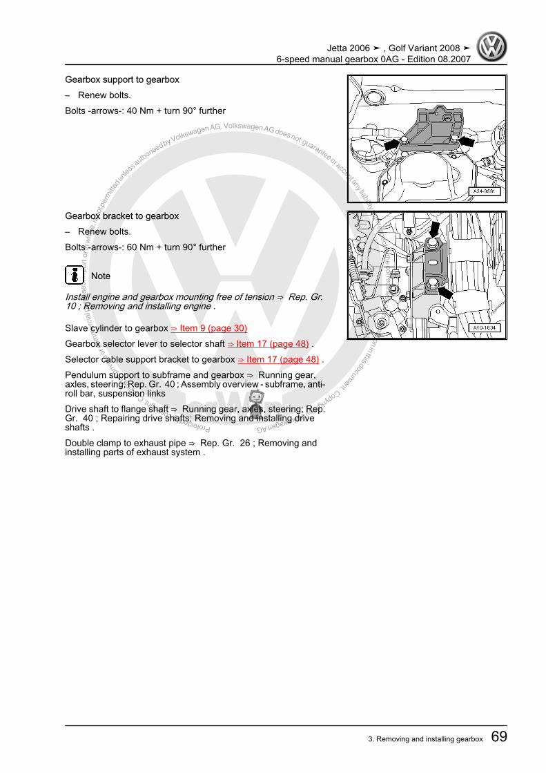
Protected by copyright. C
opying
for p
rivat
e or
com
mer
cial
pur
pose
s, in
par
t or i
n w
hole
, is
not p
erm
itted
unles
s authorise
d by Volkswagen AG. Volkswagen AG does not guarantee or accept any liability with respect to the correctness ofinform
ation in this document.Copyright by Volkswagen AG.
Gearbox support to gearbox– Renew bolts.Bolts -arrows-: 40 Nm + turn 90° further
Gearbox bracket to gearbox– Renew bolts.Bolts -arrows-: 60 Nm + turn 90° further
Note
Install engine and gearbox mounting free of tension ⇒ Rep. Gr. 10 ; Removing and installing engine .
Slave cylinder to gearbox ⇒ Item 9 (page 30)Gearbox selector lever to selector shaft ⇒ Item 17 (page 48) .Selector cable support bracket to gearbox ⇒ Item 17 (page 48) .Pendulum support to subframe and gearbox ⇒ Running gear,axles, steering; Rep. Gr. 40 ; Assembly overview - subframe, anti-roll bar, suspension linksDrive shaft to flange shaft ⇒ Running gear, axles, steering; Rep.Gr. 40 ; Repairing drive shafts; Removing and installing driveshafts .Double clamp to exhaust pipe ⇒ Rep. Gr. 26 ; Removing andinstalling parts of exhaust system .
Jetta 2006 ➤ , Golf Variant 2008 ➤6-speed manual gearbox 0AG - Edition 08.2007
3. Removing and installing gearbox 69
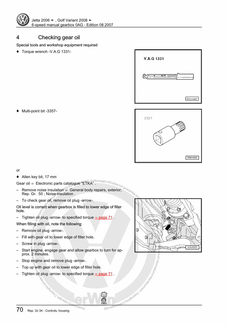
Protected by copyright. C
opying
for p
rivat
e or
com
mer
cial
pur
pose
s, in
par
t or i
n w
hole
, is
not p
erm
itted
unles
s authorise
d by Volkswagen AG. Volkswagen AG does not guarantee or accept any liability with respect to the correctness ofinform
ation in this document.Copyright by Volkswagen AG.
4 Checking gear oilSpecial tools and workshop equipment required♦ Torque wrench -V.A.G 1331-
♦ Multi-point bit -3357-
or♦ Allen key bit, 17 mmGear oil ⇒ Electronic parts catalogue “ETKA” .– Remove noise insulation ⇒ General body repairs, exterior;
Rep. Gr. 50 ; Noise insulation .– To check gear oil, remove oil plug -arrow-.Oil level is correct when gearbox is filled to lower edge of fillerhole.– Tighten oil plug -arrow- to specified torque ⇒ page 71 .When filling with oil, note the following:– Remove oil plug -arrow-.– Fill with gear oil to lower edge of filler hole.– Screw in plug -arrow-.– Start engine, engage gear and allow gearbox to turn for ap‐
prox. 2 minutes.– Stop engine and remove plug -arrow-.– Top up with gear oil to lower edge of filler hole.– Tighten oil plug -arrow- to specified torque ⇒ page 71 .
Jetta 2006 ➤ , Golf Variant 2008 ➤6-speed manual gearbox 0AG - Edition 08.2007
70 Rep. Gr.34 - Controls, housing

Protected by copyright. C
opying
for p
rivat
e or
com
mer
cial
pur
pose
s, in
par
t or i
n w
hole
, is
not p
erm
itted
unles
s authorise
d by Volkswagen AG. Volkswagen AG does not guarantee or accept any liability with respect to the correctness ofinform
ation in this document.Copyright by Volkswagen AG.
Various versions of oil filler and drain plugsI - Oil filler or oil drain plug with multi-point socket head 25 NmII - Oil filler or oil drain plug with hexagon socket head 30 Nm– Install noise insulation ⇒ General body repairs, exterior; Rep.
Gr. 50 ; Noise insulation .
Jetta 2006 ➤ , Golf Variant 2008 ➤6-speed manual gearbox 0AG - Edition 08.2007
4. Checking gear oil 71

Protected by copyright. C
opying
for p
rivat
e or
com
mer
cial
pur
pose
s, in
par
t or i
n w
hole
, is
not p
erm
itted
unles
s authorise
d by Volkswagen AG. Volkswagen AG does not guarantee or accept any liability with respect to the correctness ofinform
ation in this document.Copyright by Volkswagen AG.
5 Dismantling and assembling gearbox
5.1 Overview - gearbox
1 - 1st gear2 - 2nd gear3 - 3rd gear4 - 4th gear5 - 5th gear6 - 6th gear7 - Gearbox housing cover8 - Gearbox housing9 - Reverse gear10 - Selector mechanism
❑ (Selector forks)11 - Clutch housing12 - Input shaft13 - Output shaft14 - Differential
Jetta 2006 ➤ , Golf Variant 2008 ➤6-speed manual gearbox 0AG - Edition 08.2007
72 Rep. Gr.34 - Controls, housing
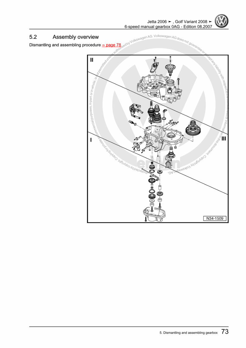
Protected by copyright. C
opying
for p
rivat
e or
com
mer
cial
pur
pose
s, in
par
t or i
n w
hole
, is
not p
erm
itted
unles
s authorise
d by Volkswagen AG. Volkswagen AG does not guarantee or accept any liability with respect to the correctness ofinform
ation in this document.Copyright by Volkswagen AG.
5.2 Assembly overviewDismantling and assembling procedure ⇒ page 78
Jetta 2006 ➤ , Golf Variant 2008 ➤6-speed manual gearbox 0AG - Edition 08.2007
5. Dismantling and assembling gearbox 73

Protected by copyright. C
opying
for p
rivat
e or
com
mer
cial
pur
pose
s, in
par
t or i
n w
hole
, is
not p
erm
itted
unles
s authorise
d by Volkswagen AG. Volkswagen AG does not guarantee or accept any liability with respect to the correctness ofinform
ation in this document.Copyright by Volkswagen AG.
I - Assembly overview - removing and installing cover for gearboxhousing and 5th and 6th gear ⇒ page 74II - Assembly overview - removing and installing clutch housing⇒ page 76III - Assembly overview - removing and installing input shaft, out‐put shaft, differential and selector forks ⇒ page 77
5.3 Assembly overview - removing and installing cover for gearbox housing and5th and 6th gear
1 - Gearbox housing❑ Repairing ⇒ page 91
2 - Gear wheel for 5th gear❑ Removing and installing
⇒ page 783 - Sleeve4 - Gear wheel for 6th gear
❑ Removing and installing⇒ page 78
5 - Cylindrical roller bearing in‐ner race
❑ For output shaft❑ Mark before removing❑ Do not interchange with
cylindrical roller bearinginner race of input shaft
❑ Can be renewed individ‐ually.
6 - Bolt❑ M8: 30 Nm and then turn
90° further❑ M10: 75 Nm and then
turn 45° further❑ For output shaft❑ Self-locking❑ Always renew
7 - Gearbox housing cover❑ With cylindrical roller
bearings for input andoutput shafts
❑ Repairing ⇒ page 968 - Bolt, 5 Nm then turn 90° further
❑ Always renew9 - Bolt
❑ M8: 30 Nm and then turn 90° further❑ M10: 75 Nm and then turn 45° further❑ For input shaft❑ Self-locking❑ Always renew
10 - Cylindrical roller bearing inner race❑ For input shaft
Jetta 2006 ➤ , Golf Variant 2008 ➤6-speed manual gearbox 0AG - Edition 08.2007
74 Rep. Gr.34 - Controls, housing

Protected by copyright. C
opying
for p
rivat
e or
com
mer
cial
pur
pose
s, in
par
t or i
n w
hole
, is
not p
erm
itted
unles
s authorise
d by Volkswagen AG. Volkswagen AG does not guarantee or accept any liability with respect to the correctness ofinform
ation in this document.Copyright by Volkswagen AG.
❑ Mark before removing❑ Do not interchange with cylinder roller bearing inner race of output shaft❑ Can be renewed individually.
11 - Thrust washer12 - Inner race for cylindrical roller bearing with thrust washer
❑ For input shaft❑ Installed in some gearboxes❑ Allocate according to ⇒ Electronic parts catalogue “ETKA”
13 - Synchromeshed gear for 6th gear14 - Synchro-ring for 6th gear15 - Needle bearing
❑ One-piece❑ For 6th gear❑ Allocate according to ⇒ Electronic parts catalogue “ETKA”❑ Replace together with sleeve.
16 - Needle bearing❑ Two-part❑ For 6th gear❑ Installed in some gearboxes❑ Allocate according to ⇒ Electronic parts catalogue “ETKA”❑ Replace together with sleeve.
17 - Sleeve❑ For 6th gear needle bearing❑ Renew together with needle bearing.
18 - Locking collar with synchro-hub for 5th and 6th gears❑ Dismantling and assembling ⇒ page 107
19 - Selector fork for 5th and 6th gear20 - Pivot pin
❑ For 5th gear selector fork.21 - Synchro-ring for 5th gear
❑ Will be damaged during removal of input shaft❑ Always renew
22 - Synchromeshed gear for 5th gear23 - Needle bearing
❑ For 5th gear
Jetta 2006 ➤ , Golf Variant 2008 ➤6-speed manual gearbox 0AG - Edition 08.2007
5. Dismantling and assembling gearbox 75

Protected by copyright. C
opying
for p
rivat
e or
com
mer
cial
pur
pose
s, in
par
t or i
n w
hole
, is
not p
erm
itted
unles
s authorise
d by Volkswagen AG. Volkswagen AG does not guarantee or accept any liability with respect to the correctness ofinform
ation in this document.Copyright by Volkswagen AG.
5.4 Assembly overview - removing and installing clutch housing
1 - Countersunk bolt, 25 Nm2 - Flange shaft with compres‐sion spring
❑ Removing and installing⇒ page 78
❑ Assembling⇒ page 129
3 - Bolt, 5 Nm then turn 90° fur‐ther
❑ Always renew4 - Clutch housing
❑ Repairing ⇒ page 915 - Gearbox housing
❑ Repairing ⇒ page 916 - Clutch release lever
❑ With guide sleeve andrelease bearing
❑ Removing and installing⇒ page 78
7 - Bolt❑ Removing and installing
⇒ page 29
Jetta 2006 ➤ , Golf Variant 2008 ➤6-speed manual gearbox 0AG - Edition 08.2007
76 Rep. Gr.34 - Controls, housing
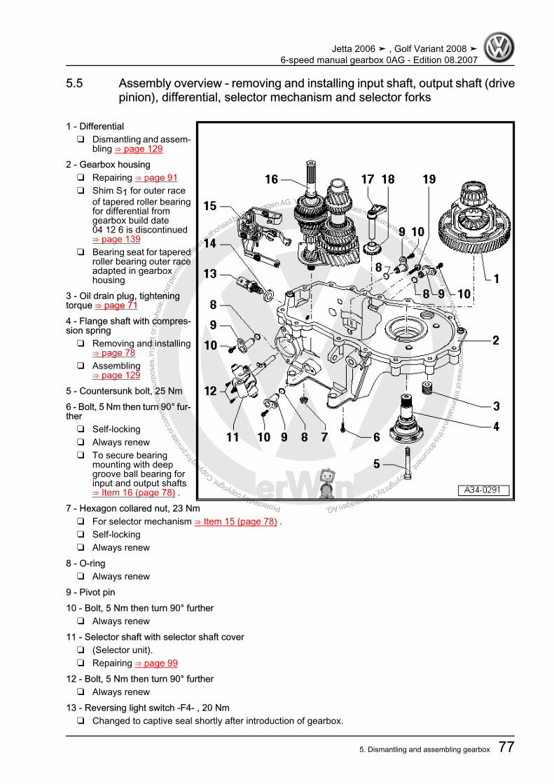
Protected by copyright. C
opying
for p
rivat
e or
com
mer
cial
pur
pose
s, in
par
t or i
n w
hole
, is
not p
erm
itted
unles
s authorise
d by Volkswagen AG. Volkswagen AG does not guarantee or accept any liability with respect to the correctness ofinform
ation in this document.Copyright by Volkswagen AG.
5.5 Assembly overview - removing and installing input shaft, output shaft (drivepinion), differential, selector mechanism and selector forks
1 - Differential❑ Dismantling and assem‐
bling ⇒ page 1292 - Gearbox housing
❑ Repairing ⇒ page 91❑ Shim S1 for outer race
of tapered roller bearingfor differential fromgearbox build date04 12 6 is discontinued⇒ page 139
❑ Bearing seat for taperedroller bearing outer raceadapted in gearboxhousing
3 - Oil drain plug, tighteningtorque ⇒ page 714 - Flange shaft with compres‐sion spring
❑ Removing and installing⇒ page 78
❑ Assembling⇒ page 129
5 - Countersunk bolt, 25 Nm6 - Bolt, 5 Nm then turn 90° fur‐ther
❑ Self-locking❑ Always renew❑ To secure bearing
mounting with deepgroove ball bearing forinput and output shafts⇒ Item 16 (page 78) .
7 - Hexagon collared nut, 23 Nm❑ For selector mechanism ⇒ Item 15 (page 78) .❑ Self-locking❑ Always renew
8 - O-ring❑ Always renew
9 - Pivot pin10 - Bolt, 5 Nm then turn 90° further
❑ Always renew11 - Selector shaft with selector shaft cover
❑ (Selector unit).❑ Repairing ⇒ page 99
12 - Bolt, 5 Nm then turn 90° further❑ Always renew
13 - Reversing light switch -F4- , 20 Nm❑ Changed to captive seal shortly after introduction of gearbox.
Jetta 2006 ➤ , Golf Variant 2008 ➤6-speed manual gearbox 0AG - Edition 08.2007
5. Dismantling and assembling gearbox 77
Protected by copyright. C
opying
for p
rivat
e or
com
mer
cial
pur
pose
s, in
par
t or i
n w
hole
, is
not p
erm
itted
unles
s authorise
d by Volkswagen AG. Volkswagen AG does not guarantee or accept any liability with respect to the correctness ofinform
ation in this document.Copyright by Volkswagen AG.
14 - Seal❑ Always renew, if part of original equipment
15 - Selector mechanism❑ (Selector forks)❑ Repairing ⇒ page 102
16 - Input shaft and output shaft with bearing mounting and deep groove ball bearing❑ If bearing mounting is separated from gearbox housing, then mounting must always be renewed.❑ Pressing bearing support off and on: Dismantling and assembling input shaft ⇒ Item 14 (page 111) .❑ Dismantling and assembling input shaft ⇒ page 107 .❑ Dismantling and assembling output shaft ⇒ page 117 .
17 - Reverse gear shaft18 - Reverse gear19 - Bolt, 25 Nm then turn 90° further
❑ Always renew❑ For securing shaft for reverse gear.
5.6 Dismantling and assembling procedureRemoving and installing gearbox housing cover, clutch housing,selector shaft with selector mechanism cover, input shaft, outputshaft, differential and selector mechanism
Jetta 2006 ➤ , Golf Variant 2008 ➤6-speed manual gearbox 0AG - Edition 08.2007
78 Rep. Gr.34 - Controls, housing

Protected by copyright. C
opying
for p
rivat
e or
com
mer
cial
pur
pose
s, in
par
t or i
n w
hole
, is
not p
erm
itted
unles
s authorise
d by Volkswagen AG. Volkswagen AG does not guarantee or accept any liability with respect to the correctness ofinform
ation in this document.Copyright by Volkswagen AG.
Special tools and workshopequipment required♦ Support clamp -VW 313-♦ Thrust plate -VW 401-♦ Thrust plate -VW 402-♦ Press tool -VW 412-♦ Guide pin -T10079-♦ Gearbox support -3221-
(modifying ⇒ page 81 )
Jetta 2006 ➤ , Golf Variant 2008 ➤6-speed manual gearbox 0AG - Edition 08.2007
5. Dismantling and assembling gearbox 79
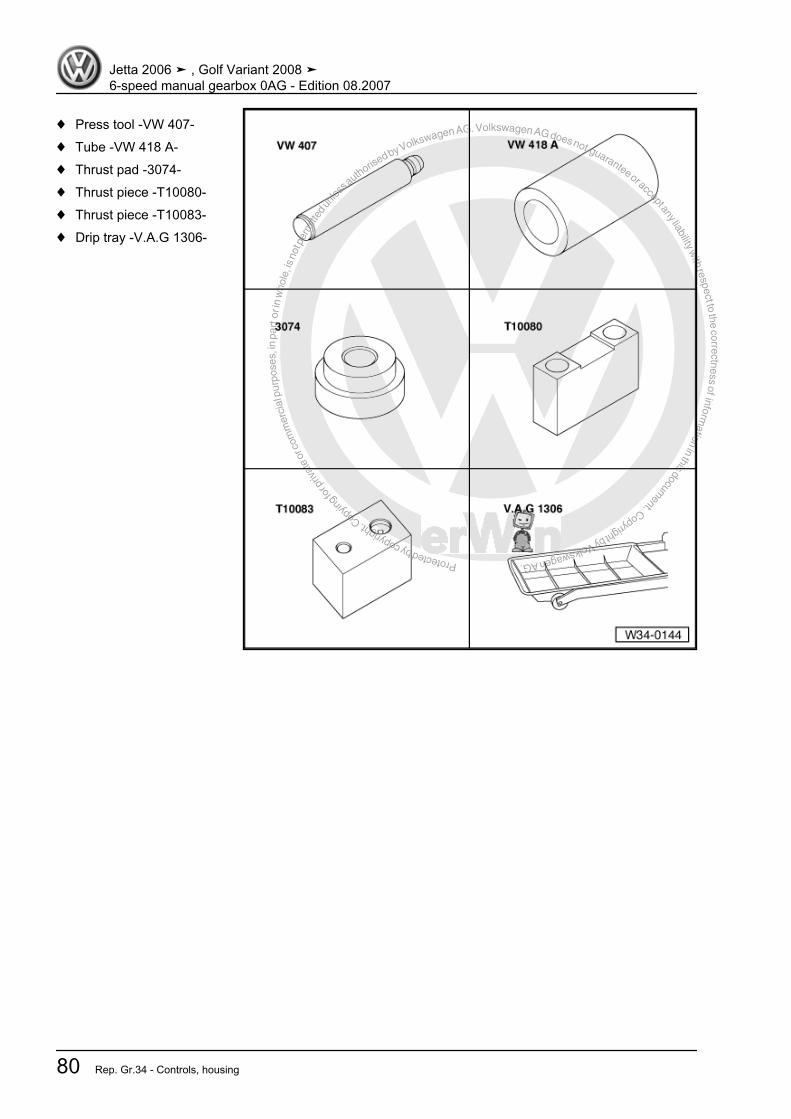
Protected by copyright. C
opying
for p
rivat
e or
com
mer
cial
pur
pose
s, in
par
t or i
n w
hole
, is
not p
erm
itted
unles
s authorise
d by Volkswagen AG. Volkswagen AG does not guarantee or accept any liability with respect to the correctness ofinform
ation in this document.Copyright by Volkswagen AG.
♦ Press tool -VW 407-♦ Tube -VW 418 A-♦ Thrust pad -3074-♦ Thrust piece -T10080-♦ Thrust piece -T10083-♦ Drip tray -V.A.G 1306-
Jetta 2006 ➤ , Golf Variant 2008 ➤6-speed manual gearbox 0AG - Edition 08.2007
80 Rep. Gr.34 - Controls, housing
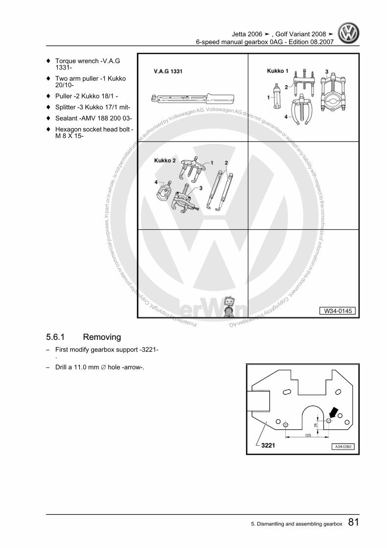
Protected by copyright. C
opying
for p
rivat
e or
com
mer
cial
pur
pose
s, in
par
t or i
n w
hole
, is
not p
erm
itted
unles
s authorise
d by Volkswagen AG. Volkswagen AG does not guarantee or accept any liability with respect to the correctness ofinform
ation in this document.Copyright by Volkswagen AG.
♦ Torque wrench -V.A.G1331-
♦ Two arm puller -1 Kukko20/10-
♦ Puller -2 Kukko 18/1 -♦ Splitter -3 Kukko 17/1 mit-♦ Sealant -AMV 188 200 03-♦ Hexagon socket head bolt -
M 8 X 15-
5.6.1 Removing– First modify gearbox support -3221-
.– Drill a 11.0 mm ∅ hole -arrow-.
Jetta 2006 ➤ , Golf Variant 2008 ➤6-speed manual gearbox 0AG - Edition 08.2007
5. Dismantling and assembling gearbox 81
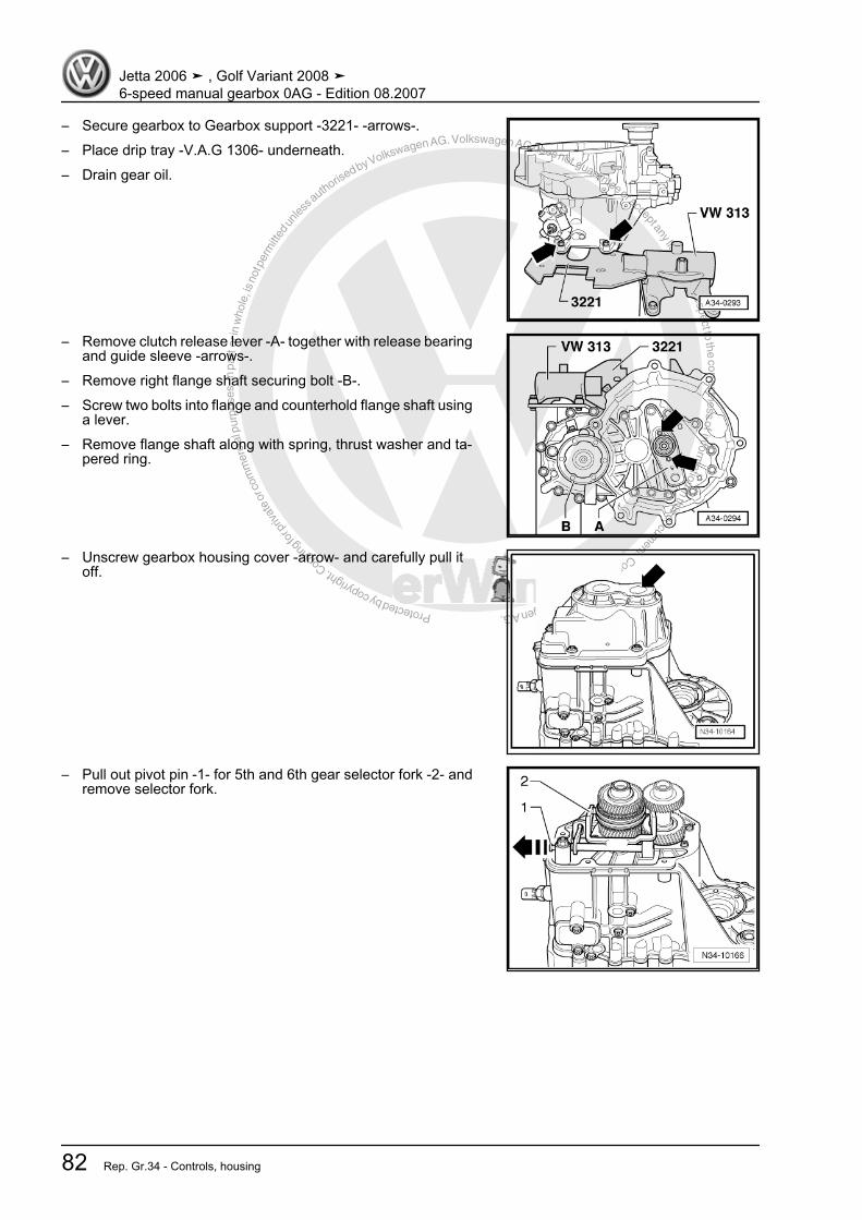
Protected by copyright. C
opying
for p
rivat
e or
com
mer
cial
pur
pose
s, in
par
t or i
n w
hole
, is
not p
erm
itted
unles
s authorise
d by Volkswagen AG. Volkswagen AG does not guarantee or accept any liability with respect to the correctness ofinform
ation in this document.Copyright by Volkswagen AG.
– Secure gearbox to Gearbox support -3221- -arrows-.– Place drip tray -V.A.G 1306- underneath.– Drain gear oil.
– Remove clutch release lever -A- together with release bearingand guide sleeve -arrows-.
– Remove right flange shaft securing bolt -B-.– Screw two bolts into flange and counterhold flange shaft using
a lever.– Remove flange shaft along with spring, thrust washer and ta‐
pered ring.
– Unscrew gearbox housing cover -arrow- and carefully pull itoff.
– Pull out pivot pin -1- for 5th and 6th gear selector fork -2- andremove selector fork.
Jetta 2006 ➤ , Golf Variant 2008 ➤6-speed manual gearbox 0AG - Edition 08.2007
82 Rep. Gr.34 - Controls, housing

Protected by copyright. C
opying
for p
rivat
e or
com
mer
cial
pur
pose
s, in
par
t or i
n w
hole
, is
not p
erm
itted
unles
s authorise
d by Volkswagen AG. Volkswagen AG does not guarantee or accept any liability with respect to the correctness ofinform
ation in this document.Copyright by Volkswagen AG.
– Remove bolts -A- for inner bearing races from input and outputshafts, engaging 5th gear -arrow 1- and 1st gear -arrow 2- and-arrow 3-.
– Input shaft and output shaft are locked when both gears areengaged. Both bolts can now be loosened.
Note
If shafts are not to be renewed, carefully clean residual lockingmaterial out of threaded holes using a thread chaser.
– Pull off 6th gear wheel with cylindrical roller bearing inner racefor output shaft.
A- Two arm puller - Kukko 20/10-B- Hexagon socket head bolt -M 8 x 15-
– Tighten splitter - Kukko 17/1- -A- behind constant mesh teethof synchromeshed gear for 6th gear (not dog teeth) -arrow-.
A- Splitter - Kukko 17/1-B- Hexagon socket head bolt -M 8 x 15-C- Puller - Kukko 18/1-– Pull off 6th gear wheel with cylindrical roller bearing inner race
for input shaft and thrust washer.– Remove locking collar for 5th and 6th gear with locking pieces.
Jetta 2006 ➤ , Golf Variant 2008 ➤6-speed manual gearbox 0AG - Edition 08.2007
5. Dismantling and assembling gearbox 83

Protected by copyright. C
opying
for p
rivat
e or
com
mer
cial
pur
pose
s, in
par
t or i
n w
hole
, is
not p
erm
itted
unles
s authorise
d by Volkswagen AG. Volkswagen AG does not guarantee or accept any liability with respect to the correctness ofinform
ation in this document.Copyright by Volkswagen AG.
– Tighten splitter - Kukko 17/1- -A- below synchro-ring for 5thgear -1-. This presses synchro-ring against synchro-hub -2-.
A- Splitter - Kukko 17/1-B- Hexagon socket head bolt -M 8 x 15-C- Puller - Kukko 18/1-– Pull off synchro-hub for 5th and 6th gear with 6th gear needle
bearing inner race and 5th gear synchro-ring.
Note
The synchro-ring for 5th gear must always be renewed after it ispulled off.
– Remove flange shaft securing bolts by screwing two bolts intoflange and counterholding flange shaft with a lever.
– Pull out flange shaft -1- with spring.– Remove sleeve -2-, gear wheel for 5th gear -3- and synchro‐
meshed gear for 5th gear with needle bearing -4-.– Unscrew hexagon collared nut -5- for securing reverse gear
selector mechanism.– Remove bearing mounting securing bolts -6- from input and
output shafts.– Turn gearbox in support bracket so that clutch housing is up‐
wards.– Remove securing bolts from clutch housing side for securing
clutch housing to gearbox housing.– Remove clutch housing, if necessary carefully levering up all
around along protruding housing flange and alternating be‐tween sides, being careful not to damage sealing surfaces.
– Do not cant the clutch housing. This prevents damage to rollerbearings and their bearing seats on the input and outputshafts.
– Remove differential -A- from gearbox housing.
Jetta 2006 ➤ , Golf Variant 2008 ➤6-speed manual gearbox 0AG - Edition 08.2007
84 Rep. Gr.34 - Controls, housing
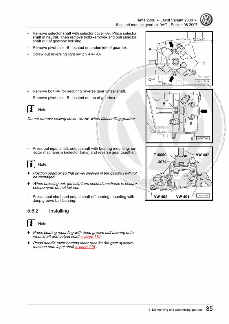
Protected by copyright. C
opying
for p
rivat
e or
com
mer
cial
pur
pose
s, in
par
t or i
n w
hole
, is
not p
erm
itted
unles
s authorise
d by Volkswagen AG. Volkswagen AG does not guarantee or accept any liability with respect to the correctness ofinform
ation in this document.Copyright by Volkswagen AG.
– Remove selector shaft with selector cover -A-. Place selectorshaft in neutral. Then remove bolts -arrows- and pull selectorshaft out of gearbox housing.
– Remove pivot pins -B- located on underside of gearbox.– Screw out reversing light switch -F4- -C-.
– Remove bolt -A- for securing reverse gear wheel shaft.– Remove pivot pins -B- located on top of gearbox.
Note
Do not remove sealing cover -arrow- when dismantling gearbox.
– Press out input shaft, output shaft with bearing mounting, se‐lector mechanism (selector forks) and reverse gear together.
Note
♦ Position gearbox so that dowel sleeves in the gearbox will notbe damaged.
♦ When pressing out, get help from second mechanic to ensurecomponents do not fall out.
– Press input shaft and output shaft off bearing mounting withdeep groove ball bearing.
5.6.2 Installing
Note
♦ Press bearing mounting with deep groove ball bearing ontoinput shaft and output shaft ⇒ page 115 .
♦ Press needle roller bearing inner race for 5th gear synchro‐meshed onto input shaft ⇒ page 115 .
Jetta 2006 ➤ , Golf Variant 2008 ➤6-speed manual gearbox 0AG - Edition 08.2007
5. Dismantling and assembling gearbox 85
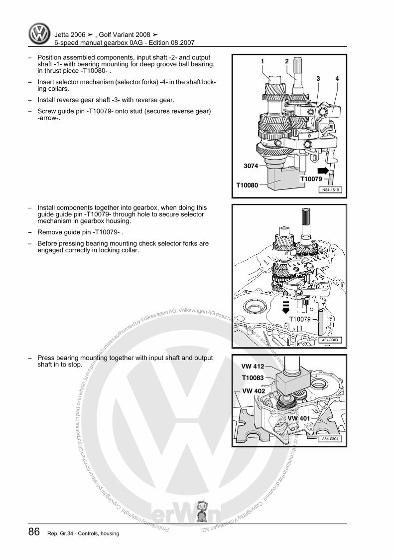
Protected by copyright. C
opying
for p
rivat
e or
com
mer
cial
pur
pose
s, in
par
t or i
n w
hole
, is
not p
erm
itted
unles
s authorise
d by Volkswagen AG. Volkswagen AG does not guarantee or accept any liability with respect to the correctness ofinform
ation in this document.Copyright by Volkswagen AG.
– Position assembled components, input shaft -2- and outputshaft -1- with bearing mounting for deep groove ball bearing,in thrust piece -T10080- .
– Insert selector mechanism (selector forks) -4- in the shaft lock‐ing collars.
– Install reverse gear shaft -3- with reverse gear.– Screw guide pin -T10079- onto stud (secures reverse gear)
-arrow-.
– Install components together into gearbox, when doing thisguide guide pin -T10079- through hole to secure selectormechanism in gearbox housing.
– Remove guide pin -T10079- .– Before pressing bearing mounting check selector forks are
engaged correctly in locking collar.
– Press bearing mounting together with input shaft and outputshaft in to stop.
Jetta 2006 ➤ , Golf Variant 2008 ➤6-speed manual gearbox 0AG - Edition 08.2007
86 Rep. Gr.34 - Controls, housing

Protected by copyright. C
opying
for p
rivat
e or
com
mer
cial
pur
pose
s, in
par
t or i
n w
hole
, is
not p
erm
itted
unles
s authorise
d by Volkswagen AG. Volkswagen AG does not guarantee or accept any liability with respect to the correctness ofinform
ation in this document.Copyright by Volkswagen AG.
– Install bolt -A- for securing reverse gear wheel shaft.– Install pivot pin -B- in bottom of gearbox.
– Screw in reversing light switch -F4- -C-.– Install pivot pin -B- in top of gearbox.– Place selector plates in neutral.– Apply sealant -AMV 188 200 03- evenly to sealing surface of
selector mechanism cover.– Install selector shaft with selector cover -A-. Then tighten bolts
-arrows-.
– Using new bolts -A- tighten bearing mounting for input andoutput shafts.
Note
Tighten bolts to specified torque, working from centre outwardsalternately and diagonally.
– Tighten hexagon collared nut -B- for securing selector mech‐anism (selector forks).
– Insert input and output shafts together with gearbox housinginto thrust block -T10083- .
– Install gear wheel for 5th gear -1- and sleeve -2-.
Installation position, 5th gear wheelThe high shoulder -arrow- faces gearbox housing cover.– Install 5th gear synchromeshed gear -3- with needle bearing.– Place 5th gear synchro-ring on synchromeshed gear.
Jetta 2006 ➤ , Golf Variant 2008 ➤6-speed manual gearbox 0AG - Edition 08.2007
5. Dismantling and assembling gearbox 87
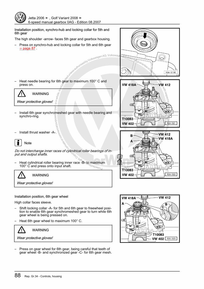
Protected by copyright. C
opying
for p
rivat
e or
com
mer
cial
pur
pose
s, in
par
t or i
n w
hole
, is
not p
erm
itted
unles
s authorise
d by Volkswagen AG. Volkswagen AG does not guarantee or accept any liability with respect to the correctness ofinform
ation in this document.Copyright by Volkswagen AG.
Installation position, synchro-hub and locking collar for 5th and6th gearThe high shoulder -arrow- faces 5th gear and gearbox housing.– Press on synchro-hub and locking collar for 5th and 6th gear
⇒ page 87 .
– Heat needle bearing for 6th gear to maximum 100° C andpress on.
WARNING
Wear protective gloves!
– Install 6th gear synchromeshed gear with needle bearing andsynchro-ring.
– Install thrust washer -A-.
Note
Do not interchange inner races of cylindrical roller bearings of in‐put and output shafts.
– Heat cylindrical roller bearing inner race -B- to maximum100° C and press onto input shaft.
WARNING
Wear protective gloves!
Installation position, 6th gear wheelHigh collar faces sleeve.– Shift locking collar -A- for 5th and 6th gear to freewheel posi‐
tion to enable 6th gear synchromeshed gear to turn while 6thgear wheel is being pressed on.
– Heat 6th gear wheel to maximum 100° C.
WARNING
Wear protective gloves!
– Press on gear wheel for 6th gear, being careful that teeth ofgear wheel -B- and synchronized gear -C- for 6th gear mesh.
Jetta 2006 ➤ , Golf Variant 2008 ➤6-speed manual gearbox 0AG - Edition 08.2007
88 Rep. Gr.34 - Controls, housing

Protected by copyright. C
opying
for p
rivat
e or
com
mer
cial
pur
pose
s, in
par
t or i
n w
hole
, is
not p
erm
itted
unles
s authorise
d by Volkswagen AG. Volkswagen AG does not guarantee or accept any liability with respect to the correctness ofinform
ation in this document.Copyright by Volkswagen AG.
– Heat cylindrical roller bearing inner race -A- to maximum100° C and press onto output shaft.
WARNING
Wear protective gloves!
– Insert magnet in gearbox housing.
– Install differential -A-.– Apply sealant -AMV 188 200 03- evenly to sealing surface.– Secure clutch housing to gearbox housing.– Turn gearbox in support bracket so that gearbox housing is
upwards.
– Before tightening securing bolts -A-, engage 2 gears-arrows 1- to -3-.
Jetta 2006 ➤ , Golf Variant 2008 ➤6-speed manual gearbox 0AG - Edition 08.2007
5. Dismantling and assembling gearbox 89
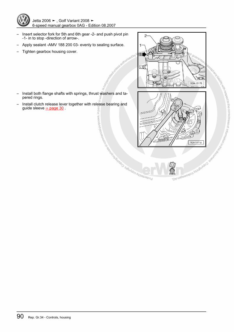
Protected by copyright. C
opying
for p
rivat
e or
com
mer
cial
pur
pose
s, in
par
t or i
n w
hole
, is
not p
erm
itted
unles
s authorise
d by Volkswagen AG. Volkswagen AG does not guarantee or accept any liability with respect to the correctness ofinform
ation in this document.Copyright by Volkswagen AG.
– Insert selector fork for 5th and 6th gear -2- and push pivot pin-1- in to stop -direction of arrow-.
– Apply sealant -AMV 188 200 03- evenly to sealing surface.– Tighten gearbox housing cover.
– Install both flange shafts with springs, thrust washers and ta‐pered rings.
– Install clutch release lever together with release bearing andguide sleeve ⇒ page 30 .
Jetta 2006 ➤ , Golf Variant 2008 ➤6-speed manual gearbox 0AG - Edition 08.2007
90 Rep. Gr.34 - Controls, housing
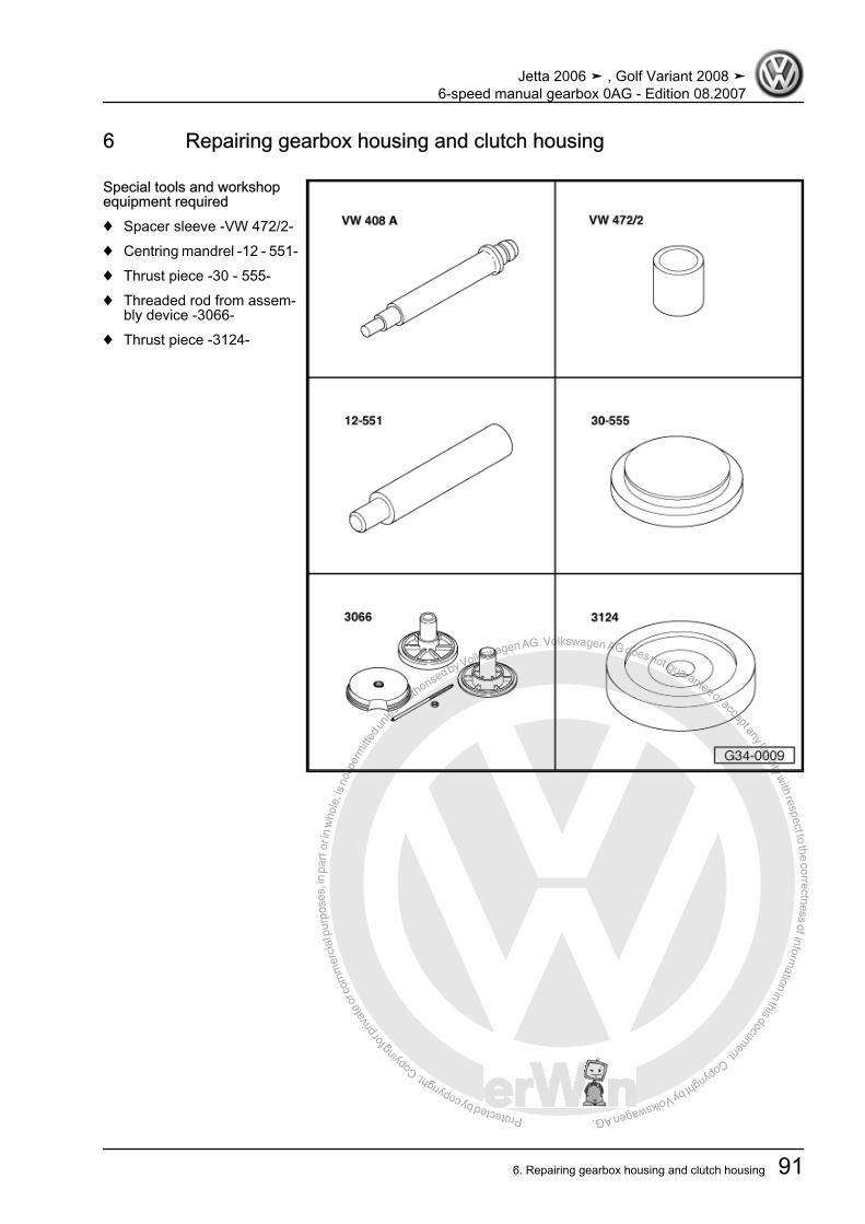
Protected by copyright. C
opying
for p
rivat
e or
com
mer
cial
pur
pose
s, in
par
t or i
n w
hole
, is
not p
erm
itted
unles
s authorise
d by Volkswagen AG. Volkswagen AG does not guarantee or accept any liability with respect to the correctness ofinform
ation in this document.Copyright by Volkswagen AG.
6 Repairing gearbox housing and clutch housing
Special tools and workshopequipment required♦ Spacer sleeve -VW 472/2-♦ Centring mandrel -12 - 551-♦ Thrust piece -30 - 555-♦ Threaded rod from assem‐
bly device -3066-♦ Thrust piece -3124-
Jetta 2006 ➤ , Golf Variant 2008 ➤6-speed manual gearbox 0AG - Edition 08.2007
6. Repairing gearbox housing and clutch housing 91
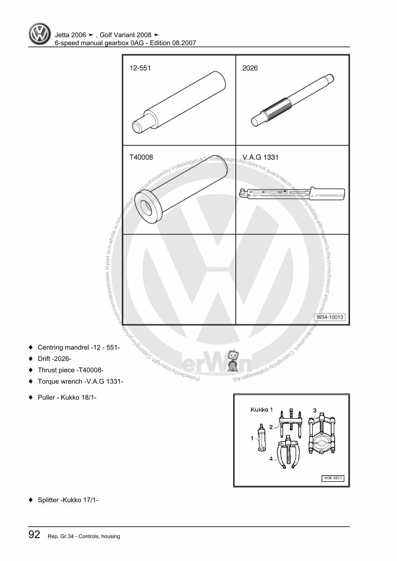
Protected by copyright. C
opying
for p
rivat
e or
com
mer
cial
pur
pose
s, in
par
t or i
n w
hole
, is
not p
erm
itted
unles
s authorise
d by Volkswagen AG. Volkswagen AG does not guarantee or accept any liability with respect to the correctness ofinform
ation in this document.Copyright by Volkswagen AG.
♦ Centring mandrel -12 - 551-♦ Drift -2026-♦ Thrust piece -T40008-♦ Torque wrench -V.A.G 1331-
♦ Puller - Kukko 18/1-
♦ Splitter -Kukko 17/1-
Jetta 2006 ➤ , Golf Variant 2008 ➤6-speed manual gearbox 0AG - Edition 08.2007
92 Rep. Gr.34 - Controls, housing
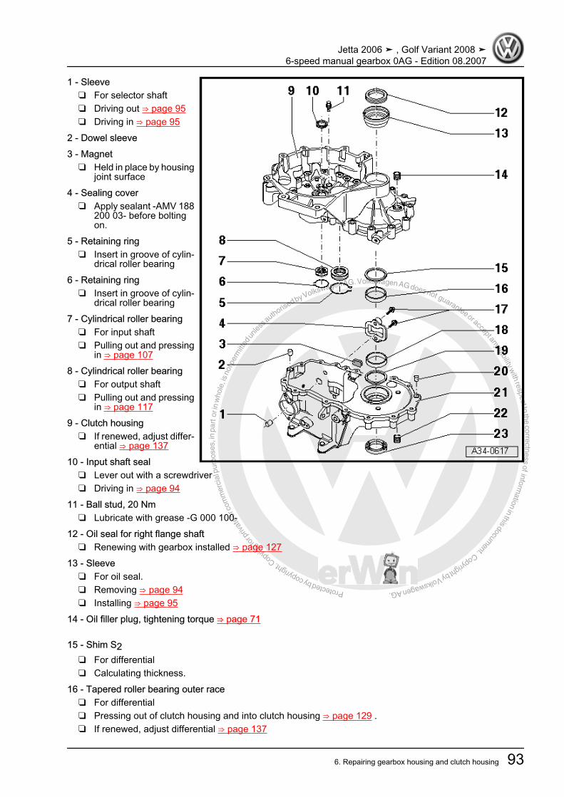
Protected by copyright. C
opying
for p
rivat
e or
com
mer
cial
pur
pose
s, in
par
t or i
n w
hole
, is
not p
erm
itted
unles
s authorise
d by Volkswagen AG. Volkswagen AG does not guarantee or accept any liability with respect to the correctness ofinform
ation in this document.Copyright by Volkswagen AG.
1 - Sleeve❑ For selector shaft❑ Driving out ⇒ page 95❑ Driving in ⇒ page 95
2 - Dowel sleeve3 - Magnet
❑ Held in place by housingjoint surface
4 - Sealing cover❑ Apply sealant -AMV 188
200 03- before boltingon.
5 - Retaining ring❑ Insert in groove of cylin‐
drical roller bearing6 - Retaining ring
❑ Insert in groove of cylin‐drical roller bearing
7 - Cylindrical roller bearing❑ For input shaft❑ Pulling out and pressing
in ⇒ page 1078 - Cylindrical roller bearing
❑ For output shaft❑ Pulling out and pressing
in ⇒ page 1179 - Clutch housing
❑ If renewed, adjust differ‐ential ⇒ page 137
10 - Input shaft seal❑ Lever out with a screwdriver❑ Driving in ⇒ page 94
11 - Ball stud, 20 Nm❑ Lubricate with grease -G 000 100-
12 - Oil seal for right flange shaft❑ Renewing with gearbox installed ⇒ page 127
13 - Sleeve❑ For oil seal.❑ Removing ⇒ page 94❑ Installing ⇒ page 95
14 - Oil filler plug, tightening torque ⇒ page 71
15 - Shim S2❑ For differential❑ Calculating thickness.
16 - Tapered roller bearing outer race❑ For differential❑ Pressing out of clutch housing and into clutch housing ⇒ page 129 .❑ If renewed, adjust differential ⇒ page 137
Jetta 2006 ➤ , Golf Variant 2008 ➤6-speed manual gearbox 0AG - Edition 08.2007
6. Repairing gearbox housing and clutch housing 93

Protected by copyright. C
opying
for p
rivat
e or
com
mer
cial
pur
pose
s, in
par
t or i
n w
hole
, is
not p
erm
itted
unles
s authorise
d by Volkswagen AG. Volkswagen AG does not guarantee or accept any liability with respect to the correctness ofinform
ation in this document.Copyright by Volkswagen AG.
17 - Bolt, 5 Nm then turn 90° further❑ Always renew
18 - Tapered roller bearing outer race❑ For differential❑ Pulling out of clutch housing and pressing into clutch housing ⇒ page 129❑ If renewed, adjust differential.
19 - Shim S1❑ For differential❑ Always 1 mm thick❑ Shim S1 discontinued as of gearbox date 04 12 6 ⇒ page 139❑ Bearing seat for tapered roller bearing outer race adapted in gearbox housing
20 - Dowel sleeve21 - Gearbox housing
❑ Shim S1 discontinued as of gearbox date 04 12 6 ⇒ page 139❑ Bearing seat for tapered roller bearing outer race adapted in gearbox housing❑ If renewed, adjust differential ⇒ page 137
22 - Oil drain plug, tightening torque ⇒ page 71
23 - Oil seal for left flange shaft❑ Renewing with gearbox installed ⇒ page 125
Driving in input shaft oil seal flush
Pulling out sleeve for seal– Fit spacer sleeve -VW 472/2- and press tool -30 - 555- onto
differential.A- Puller - Kukko 18/1-B- Splitter - Kukko 17/1-
Jetta 2006 ➤ , Golf Variant 2008 ➤6-speed manual gearbox 0AG - Edition 08.2007
94 Rep. Gr.34 - Controls, housing
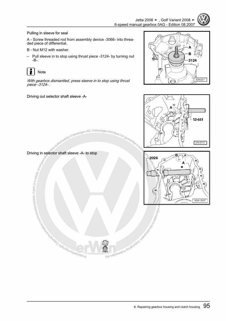
Protected by copyright. C
opying
for p
rivat
e or
com
mer
cial
pur
pose
s, in
par
t or i
n w
hole
, is
not p
erm
itted
unles
s authorise
d by Volkswagen AG. Volkswagen AG does not guarantee or accept any liability with respect to the correctness ofinform
ation in this document.Copyright by Volkswagen AG.
Pulling in sleeve for sealA - Screw threaded rod from assembly device -3066- into threa‐ded piece of differential.B - Nut M12 with washer.– Pull sleeve in to stop using thrust piece -3124- by turning nut
-B-.
Note
With gearbox dismantled, press sleeve in to stop using thrustpiece -3124- .
Driving out selector shaft sleeve -A-
Driving in selector shaft sleeve -A- to stop
Jetta 2006 ➤ , Golf Variant 2008 ➤6-speed manual gearbox 0AG - Edition 08.2007
6. Repairing gearbox housing and clutch housing 95

Protected by copyright. C
opying
for p
rivat
e or
com
mer
cial
pur
pose
s, in
par
t or i
n w
hole
, is
not p
erm
itted
unles
s authorise
d by Volkswagen AG. Volkswagen AG does not guarantee or accept any liability with respect to the correctness ofinform
ation in this document.Copyright by Volkswagen AG.
7 Repairing gearbox housing cover
Special tools and workshop equipment required♦ Press tool -VW 412-♦ Drift sleeve -40 - 21-♦ Support bridge -2011-♦ Internal puller -1 - Kukko 21/5-♦ Counter support -4 - Kukko 22/2-♦ Hot air blower -V.A.G 1416-
Jetta 2006 ➤ , Golf Variant 2008 ➤6-speed manual gearbox 0AG - Edition 08.2007
96 Rep. Gr.34 - Controls, housing
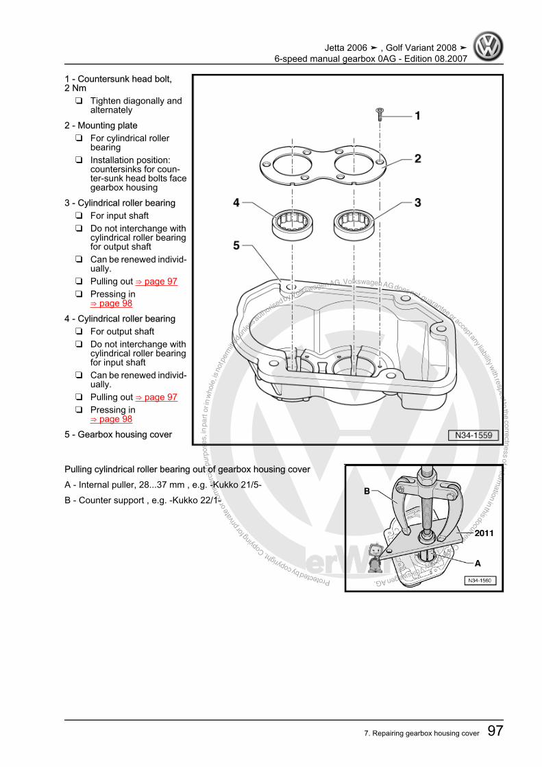
Protected by copyright. C
opying
for p
rivat
e or
com
mer
cial
pur
pose
s, in
par
t or i
n w
hole
, is
not p
erm
itted
unles
s authorise
d by Volkswagen AG. Volkswagen AG does not guarantee or accept any liability with respect to the correctness ofinform
ation in this document.Copyright by Volkswagen AG.
1 - Countersunk head bolt,2 Nm
❑ Tighten diagonally andalternately
2 - Mounting plate❑ For cylindrical roller
bearing❑ Installation position:
countersinks for coun‐ter-sunk head bolts facegearbox housing
3 - Cylindrical roller bearing❑ For input shaft❑ Do not interchange with
cylindrical roller bearingfor output shaft
❑ Can be renewed individ‐ually.
❑ Pulling out ⇒ page 97❑ Pressing in
⇒ page 984 - Cylindrical roller bearing
❑ For output shaft❑ Do not interchange with
cylindrical roller bearingfor input shaft
❑ Can be renewed individ‐ually.
❑ Pulling out ⇒ page 97❑ Pressing in
⇒ page 985 - Gearbox housing cover
Pulling cylindrical roller bearing out of gearbox housing coverA - Internal puller, 28...37 mm , e.g. -Kukko 21/5-B - Counter support , e.g. -Kukko 22/1-
Jetta 2006 ➤ , Golf Variant 2008 ➤6-speed manual gearbox 0AG - Edition 08.2007
7. Repairing gearbox housing cover 97
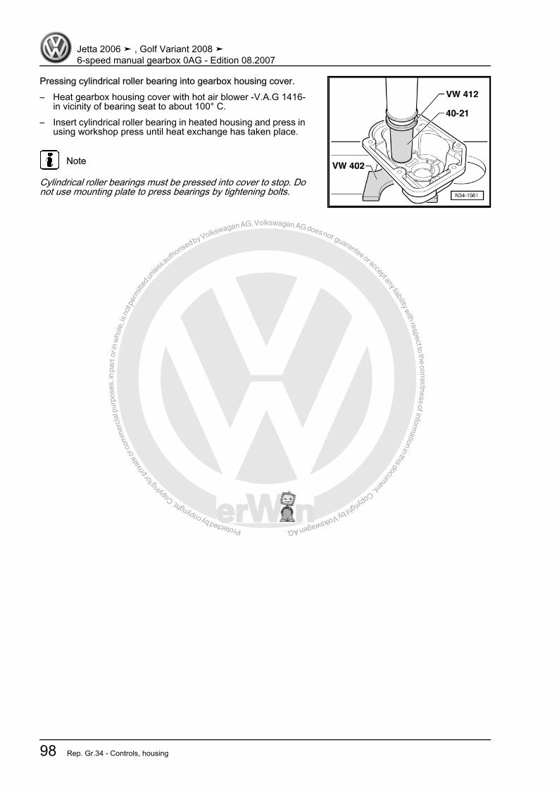
Protected by copyright. C
opying
for p
rivat
e or
com
mer
cial
pur
pose
s, in
par
t or i
n w
hole
, is
not p
erm
itted
unles
s authorise
d by Volkswagen AG. Volkswagen AG does not guarantee or accept any liability with respect to the correctness ofinform
ation in this document.Copyright by Volkswagen AG.
Pressing cylindrical roller bearing into gearbox housing cover.– Heat gearbox housing cover with hot air blower -V.A.G 1416-
in vicinity of bearing seat to about 100° C.– Insert cylindrical roller bearing in heated housing and press in
using workshop press until heat exchange has taken place.
Note
Cylindrical roller bearings must be pressed into cover to stop. Donot use mounting plate to press bearings by tightening bolts.
Jetta 2006 ➤ , Golf Variant 2008 ➤6-speed manual gearbox 0AG - Edition 08.2007
98 Rep. Gr.34 - Controls, housing

Protected by copyright. C
opying
for p
rivat
e or
com
mer
cial
pur
pose
s, in
par
t or i
n w
hole
, is
not p
erm
itted
unles
s authorise
d by Volkswagen AG. Volkswagen AG does not guarantee or accept any liability with respect to the correctness ofinform
ation in this document.Copyright by Volkswagen AG.
8 Repairing selector unitSpecial tools and workshop equipment required♦ Tube -T10203-
♦ Tube -VW 423-
♦ Torque wrench -V.A.G 1331-
Jetta 2006 ➤ , Golf Variant 2008 ➤6-speed manual gearbox 0AG - Edition 08.2007
8. Repairing selector unit 99
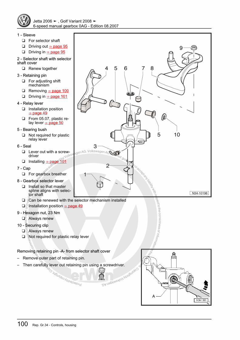
Protected by copyright. C
opying
for p
rivat
e or
com
mer
cial
pur
pose
s, in
par
t or i
n w
hole
, is
not p
erm
itted
unles
s authorise
d by Volkswagen AG. Volkswagen AG does not guarantee or accept any liability with respect to the correctness ofinform
ation in this document.Copyright by Volkswagen AG.
1 - Sleeve❑ For selector shaft❑ Driving out ⇒ page 95❑ Driving in ⇒ page 95
2 - Selector shaft with selectorshaft cover
❑ Renew together3 - Retaining pin
❑ For adjusting shiftmechanism
❑ Removing ⇒ page 100❑ Driving in ⇒ page 101
4 - Relay lever❑ Installation position
⇒ page 49❑ From 05.07, plastic re‐
lay lever ⇒ page 505 - Bearing bush
❑ Not required for plasticrelay lever
6 - Seal❑ Lever out with a screw‐
driver❑ Installing ⇒ page 101
7 - Cap❑ For gearbox breather
8 - Gearbox selector lever❑ Install so that master
spline aligns with selec‐tor shaft
❑ Can be renewed with the selector mechanism installed❑ Installation position ⇒ page 49
9 - Hexagon nut, 23 Nm❑ Always renew
10 - Securing clip❑ Always renew❑ Not required for plastic relay lever
Removing retaining pin -A- from selector shaft cover– Remove outer part of retaining pin.– Then carefully lever out retaining pin using a screwdriver.
Jetta 2006 ➤ , Golf Variant 2008 ➤6-speed manual gearbox 0AG - Edition 08.2007
100 Rep. Gr.34 - Controls, housing
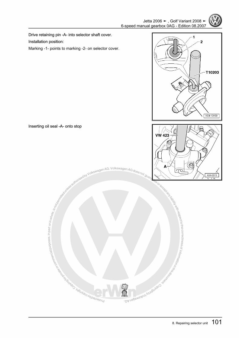
Protected by copyright. C
opying
for p
rivat
e or
com
mer
cial
pur
pose
s, in
par
t or i
n w
hole
, is
not p
erm
itted
unles
s authorise
d by Volkswagen AG. Volkswagen AG does not guarantee or accept any liability with respect to the correctness ofinform
ation in this document.Copyright by Volkswagen AG.
Drive retaining pin -A- into selector shaft cover.Installation position:Marking -1- points to marking -2- on selector cover.
Inserting oil seal -A- onto stop
Jetta 2006 ➤ , Golf Variant 2008 ➤6-speed manual gearbox 0AG - Edition 08.2007
8. Repairing selector unit 101
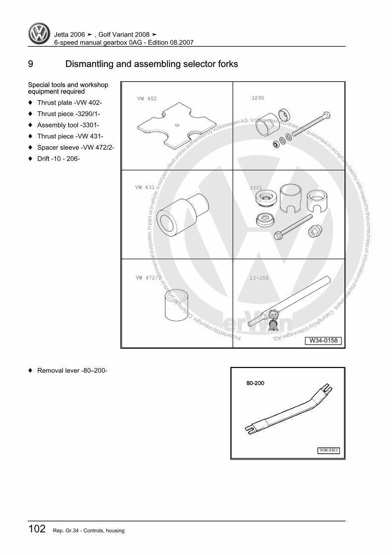
Protected by copyright. C
opying
for p
rivat
e or
com
mer
cial
pur
pose
s, in
par
t or i
n w
hole
, is
not p
erm
itted
unles
s authorise
d by Volkswagen AG. Volkswagen AG does not guarantee or accept any liability with respect to the correctness ofinform
ation in this document.Copyright by Volkswagen AG.
9 Dismantling and assembling selector forks
Special tools and workshopequipment required♦ Thrust plate -VW 402-♦ Thrust piece -3290/1-♦ Assembly tool -3301-♦ Thrust piece -VW 431-♦ Spacer sleeve -VW 472/2-♦ Drift -10 - 206-
♦ Removal lever -80–200-
Jetta 2006 ➤ , Golf Variant 2008 ➤6-speed manual gearbox 0AG - Edition 08.2007
102 Rep. Gr.34 - Controls, housing
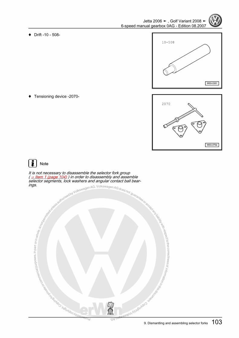
Protected by copyright. C
opying
for p
rivat
e or
com
mer
cial
pur
pose
s, in
par
t or i
n w
hole
, is
not p
erm
itted
unles
s authorise
d by Volkswagen AG. Volkswagen AG does not guarantee or accept any liability with respect to the correctness ofinform
ation in this document.Copyright by Volkswagen AG.
♦ Drift -10 - 508-
♦ Tensioning device -2070-
Note
It is not necessary to disassemble the selector fork group( ⇒ Item 1 (page 104) ) in order to disassembly and assembleselector segments, lock washers and angular contact ball bear‐ings.
Jetta 2006 ➤ , Golf Variant 2008 ➤6-speed manual gearbox 0AG - Edition 08.2007
9. Dismantling and assembling selector forks 103
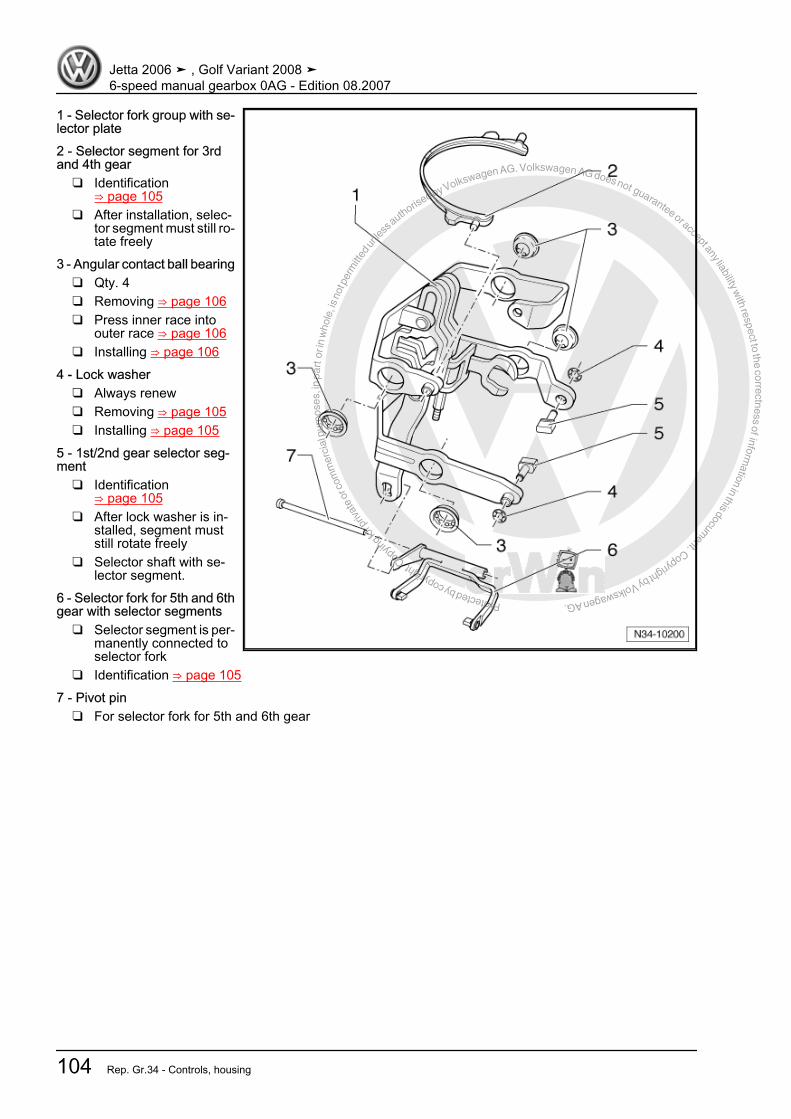
Protected by copyright. C
opying
for p
rivat
e or
com
mer
cial
pur
pose
s, in
par
t or i
n w
hole
, is
not p
erm
itted
unles
s authorise
d by Volkswagen AG. Volkswagen AG does not guarantee or accept any liability with respect to the correctness ofinform
ation in this document.Copyright by Volkswagen AG.
1 - Selector fork group with se‐lector plate2 - Selector segment for 3rdand 4th gear
❑ Identification⇒ page 105
❑ After installation, selec‐tor segment must still ro‐tate freely
3 - Angular contact ball bearing❑ Qty. 4❑ Removing ⇒ page 106❑ Press inner race into
outer race ⇒ page 106❑ Installing ⇒ page 106
4 - Lock washer❑ Always renew❑ Removing ⇒ page 105❑ Installing ⇒ page 105
5 - 1st/2nd gear selector seg‐ment
❑ Identification⇒ page 105
❑ After lock washer is in‐stalled, segment muststill rotate freely
❑ Selector shaft with se‐lector segment.
6 - Selector fork for 5th and 6thgear with selector segments
❑ Selector segment is per‐manently connected toselector fork
❑ Identification ⇒ page 1057 - Pivot pin
❑ For selector fork for 5th and 6th gear
Jetta 2006 ➤ , Golf Variant 2008 ➤6-speed manual gearbox 0AG - Edition 08.2007
104 Rep. Gr.34 - Controls, housing
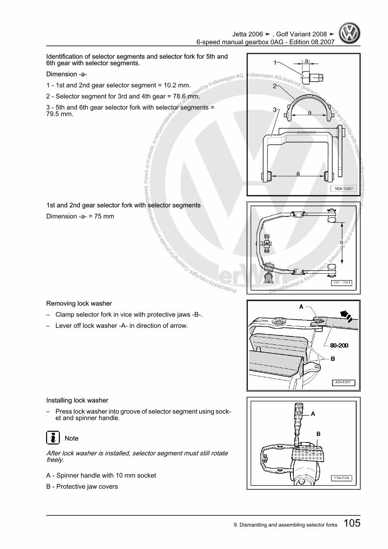
Protected by copyright. C
opying
for p
rivat
e or
com
mer
cial
pur
pose
s, in
par
t or i
n w
hole
, is
not p
erm
itted
unles
s authorise
d by Volkswagen AG. Volkswagen AG does not guarantee or accept any liability with respect to the correctness ofinform
ation in this document.Copyright by Volkswagen AG.
Identification of selector segments and selector fork for 5th and6th gear with selector segments.Dimension -a-1 - 1st and 2nd gear selector segment = 10.2 mm.2 - Selector segment for 3rd and 4th gear = 78.6 mm.3 - 5th and 6th gear selector fork with selector segments =79.5 mm.
1st and 2nd gear selector fork with selector segmentsDimension -a- = 75 mm
Removing lock washer– Clamp selector fork in vice with protective jaws -B-.– Lever off lock washer -A- in direction of arrow.
Installing lock washer– Press lock washer into groove of selector segment using sock‐
et and spinner handle.
Note
After lock washer is installed, selector segment must still rotatefreely.
A - Spinner handle with 10 mm socketB - Protective jaw covers
Jetta 2006 ➤ , Golf Variant 2008 ➤6-speed manual gearbox 0AG - Edition 08.2007
9. Dismantling and assembling selector forks 105
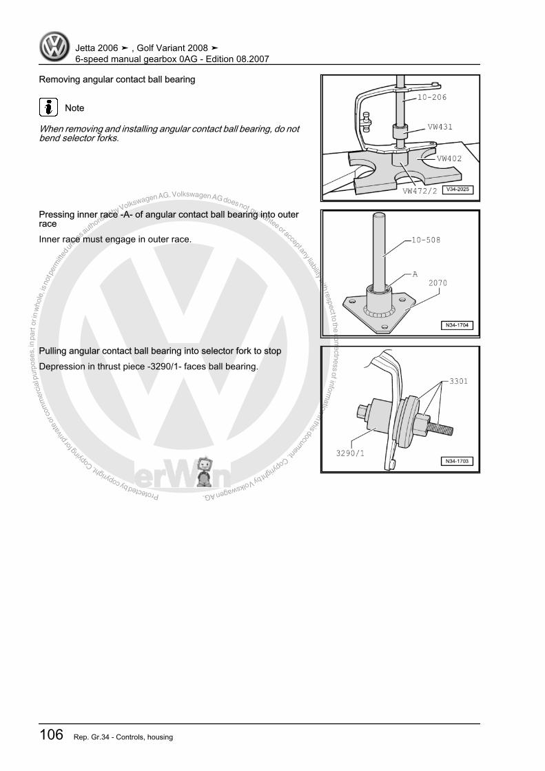
Protected by copyright. C
opying
for p
rivat
e or
com
mer
cial
pur
pose
s, in
par
t or i
n w
hole
, is
not p
erm
itted
unles
s authorise
d by Volkswagen AG. Volkswagen AG does not guarantee or accept any liability with respect to the correctness ofinform
ation in this document.Copyright by Volkswagen AG.
Removing angular contact ball bearing
Note
When removing and installing angular contact ball bearing, do notbend selector forks.
Pressing inner race -A- of angular contact ball bearing into outerraceInner race must engage in outer race.
Pulling angular contact ball bearing into selector fork to stopDepression in thrust piece -3290/1- faces ball bearing.
Jetta 2006 ➤ , Golf Variant 2008 ➤6-speed manual gearbox 0AG - Edition 08.2007
106 Rep. Gr.34 - Controls, housing
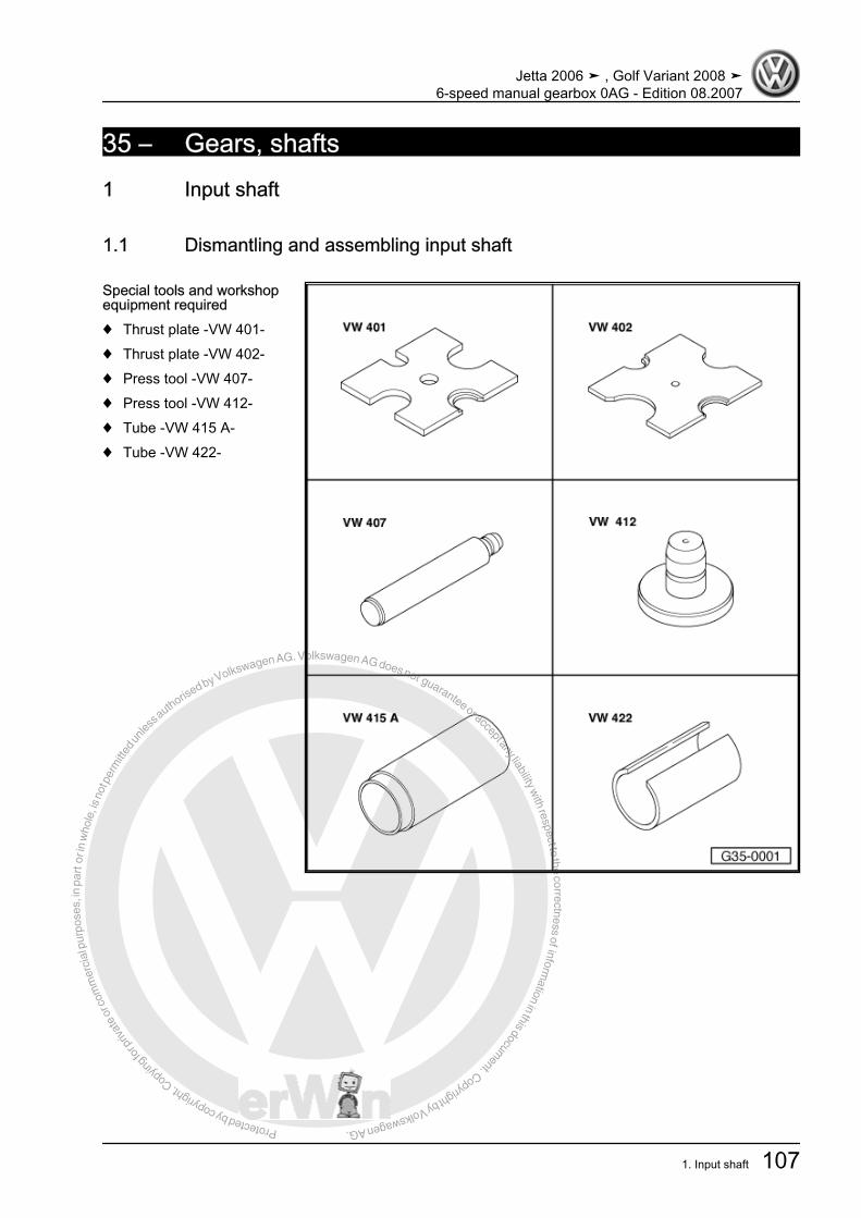
Protected by copyright. C
opying
for p
rivat
e or
com
mer
cial
pur
pose
s, in
par
t or i
n w
hole
, is
not p
erm
itted
unles
s authorise
d by Volkswagen AG. Volkswagen AG does not guarantee or accept any liability with respect to the correctness ofinform
ation in this document.Copyright by Volkswagen AG.
35 – Gears, shafts1 Input shaft
1.1 Dismantling and assembling input shaft
Special tools and workshopequipment required♦ Thrust plate -VW 401-♦ Thrust plate -VW 402-♦ Press tool -VW 407-♦ Press tool -VW 412-♦ Tube -VW 415 A-♦ Tube -VW 422-
Jetta 2006 ➤ , Golf Variant 2008 ➤6-speed manual gearbox 0AG - Edition 08.2007
1. Input shaft 107

Protected by copyright. C
opying
for p
rivat
e or
com
mer
cial
pur
pose
s, in
par
t or i
n w
hole
, is
not p
erm
itted
unles
s authorise
d by Volkswagen AG. Volkswagen AG does not guarantee or accept any liability with respect to the correctness ofinform
ation in this document.Copyright by Volkswagen AG.
♦ Spacer sleeve -VW 472/2-♦ Tube -VW 516-♦ Drift sleeve -30 - 23-♦ Drift sleeve -30 - 100-♦ Thrust piece -T10080-♦ Thrust piece -T10081-
Jetta 2006 ➤ , Golf Variant 2008 ➤6-speed manual gearbox 0AG - Edition 08.2007
108 Rep. Gr.35 - Gears, shafts
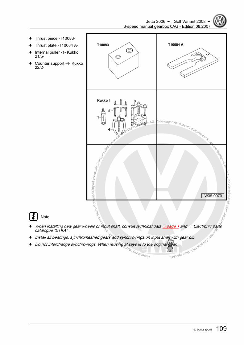
Protected by copyright. C
opying
for p
rivat
e or
com
mer
cial
pur
pose
s, in
par
t or i
n w
hole
, is
not p
erm
itted
unles
s authorise
d by Volkswagen AG. Volkswagen AG does not guarantee or accept any liability with respect to the correctness ofinform
ation in this document.Copyright by Volkswagen AG.
♦ Thrust piece -T10083-♦ Thrust plate -T10084 A-♦ Internal puller -1- Kukko
21/5-♦ Counter support -4- Kukko
22/2-
Note
♦ When installing new gear wheels or input shaft, consult technical data ⇒ page 1 and ⇒ Electronic partscatalogue “ETKA” .
♦ Install all bearings, synchromeshed gears and synchro-rings on input shaft with gear oil.♦ Do not interchange synchro-rings. When reusing always fit to the original gear.
Jetta 2006 ➤ , Golf Variant 2008 ➤6-speed manual gearbox 0AG - Edition 08.2007
1. Input shaft 109

Protected by copyright. C
opying
for p
rivat
e or
com
mer
cial
pur
pose
s, in
par
t or i
n w
hole
, is
not p
erm
itted
unles
s authorise
d by Volkswagen AG. Volkswagen AG does not guarantee or accept any liability with respect to the correctness ofinform
ation in this document.Copyright by Volkswagen AG.
1 - Bolt❑ Removing and installing
⇒ page 742 - Cylindrical roller bearing in‐ner race
❑ Combined with thrustwasher⇒ Item 3 (page 110)⇒ page 74
❑ Mark before removing❑ Do not interchange with
cylinder roller bearinginner race of outputshaft
❑ Can be renewed individ‐ually.
❑ Removing and installing⇒ page 78
3 - Thrust washer❑ Combined with inner
race of cylindrical rollerbearing⇒ Item 2 (page 110)⇒ page 74
4 - Synchromeshed gear for6th gear5 - Synchro-ring for 6th gear
❑ Check for wear⇒ page 114
6 - Needle bearing❑ For 6th gear❑ Renew together with
⇒ Item 11 (page 110)7 - Sleeve
❑ For 6th gear needle bearing❑ Renew together with ⇒ Item 6 (page 110)❑ Removing and installing ⇒ page 78
8 - Locking collar with synchro-hub for 5th and 6th gears❑ Removing and installing ⇒ page 78❑ Dismantling ⇒ page 116❑ Assembling 5th and 6th gear locking collar and synchro-hub ⇒ page 116 and ⇒ page 116 .❑ Installation position ⇒ page 116
9 - Synchro-ring for 5th gear❑ Will be damaged during removal of input shaft❑ Always renew❑ Check for wear ⇒ page 114
10 - Synchromeshed gear for 5th gear11 - Needle bearing
❑ For 5th gear❑ Renew together with sleeve.
12 - Sleeve❑ For 5th gear needle bearing
Jetta 2006 ➤ , Golf Variant 2008 ➤6-speed manual gearbox 0AG - Edition 08.2007
110 Rep. Gr.35 - Gears, shafts

Protected by copyright. C
opying
for p
rivat
e or
com
mer
cial
pur
pose
s, in
par
t or i
n w
hole
, is
not p
erm
itted
unles
s authorise
d by Volkswagen AG. Volkswagen AG does not guarantee or accept any liability with respect to the correctness ofinform
ation in this document.Copyright by Volkswagen AG.
❑ Renew together with needle bearing.❑ Press off with bearing mounting with deep groove ball bearing ⇒ page 112❑ Pressing on ⇒ page 115
13 - Gearbox housing❑ Repairing ⇒ page 91
14 - Bearing mounting with deep groove ball bearing❑ Renew deep groove ball bearing only together with bearing mounting❑ If bearing mounting is separated from gearbox housing, then mounting must always be renewed.❑ Pressing off ⇒ page 112❑ Pressing on ⇒ page 115
15 - Input shaft❑ Clean residual locking fluid from threaded hole in input shaft using a thread chaser
16 - Needle bearing❑ For 3rd gear
17 - Synchromeshed gear for 3rd gear18 - Synchro-ring for 3rd gear
❑ Check for wear ⇒ page 11419 - Locking collar with synchro-hub for 3rd and 4th gear
❑ Press off with 3rd gear synchromeshed gear ⇒ page 113❑ Dismantling ⇒ page 113❑ Installation position, locking collar and synchro-hub ⇒ page 113❑ Assembling ⇒ page 113❑ Pressing on ⇒ page 114
20 - Sleeve❑ For 4th gear needle bearing❑ Renew together with ⇒ Item 21 (page 111)❑ Press off with 3rd gear synchromeshed gear ⇒ page 113❑ Pressing on ⇒ page 114
21 - Needle bearing❑ For 4th gear❑ Renew together with ⇒ Item 20 (page 111)
22 - Synchro-ring for 4th gear❑ Check for wear ⇒ page 114
23 - Synchromeshed gear for 4th gear24 - Thrust washer25 - Cylindrical roller bearing inner race
❑ Pressing off ⇒ page 113❑ Pressing on ⇒ page 114
26 - Retaining ring❑ Renew❑ Determining thickness ⇒ page 115
27 - Cylindrical roller bearing❑ With retaining ring❑ Pulling out ⇒ page 112❑ Pressing in ⇒ page 112❑ Installation position: retaining ring in bearing faces input shaft
Jetta 2006 ➤ , Golf Variant 2008 ➤6-speed manual gearbox 0AG - Edition 08.2007
1. Input shaft 111

Protected by copyright. C
opying
for p
rivat
e or
com
mer
cial
pur
pose
s, in
par
t or i
n w
hole
, is
not p
erm
itted
unles
s authorise
d by Volkswagen AG. Volkswagen AG does not guarantee or accept any liability with respect to the correctness ofinform
ation in this document.Copyright by Volkswagen AG.
28 - Clutch housing❑ Repairing ⇒ page 91
29 - Spring❑ Installation position ⇒ page 113
30 - 3rd and 4th gear locking collar31 - 3rd and 4th gear synchro-hub32 - Locking pieces (Qty. 3)33 - Spring
❑ Installation position ⇒ page 11634 - Locking pieces (Qty. 3)35 - 5th and 6th gear synchro-hub36 - Locking collar for 5th and 6th gears
Pulling cylindrical roller bearing out of clutch housing– When pulling out, squeeze together retaining ring -arrow- of
cylindrical roller bearing, using pliers -C-.A - Counter support , e.g. -Kukko 22/1-B - Internal puller, 30...37 mm , e.g. -Kukko 21/5-
Pressing cylindrical roller bearing into clutch housing– Support gearbox housing with tube -VW 415 A- (not visible in
figure) directly below bearing support.– When pressing in, squeeze cylindrical roller bearing retaining
ring -arrow- together using pliers -A-.– Remove pliers before cylindrical roller bearing is in installation
position. Retaining ring must engage in groove of clutch hous‐ing.
Pressing off bearing mounting with deep groove ball bearing– Slide locking collar for 1st and 2nd gear towards 2nd gear.– Then slide pressure plate -T10084 A- onto input shaft to stop
from side.– Remove retaining ring.
Jetta 2006 ➤ , Golf Variant 2008 ➤6-speed manual gearbox 0AG - Edition 08.2007
112 Rep. Gr.35 - Gears, shafts
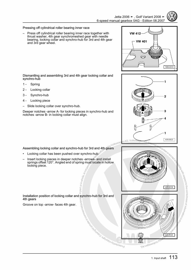
Protected by copyright. C
opying
for p
rivat
e or
com
mer
cial
pur
pose
s, in
par
t or i
n w
hole
, is
not p
erm
itted
unles
s authorise
d by Volkswagen AG. Volkswagen AG does not guarantee or accept any liability with respect to the correctness ofinform
ation in this document.Copyright by Volkswagen AG.
Pressing off cylindrical roller bearing inner race– Press off cylindrical roller bearing inner race together with
thrust washer, 4th gear synchromeshed gear with needlebearing, locking collar and synchro-hub for 3rd and 4th gearand 3rd gear wheel.
Dismantling and assembling 3rd and 4th gear locking collar andsynchro-hub1 - Spring2 - Locking collar3 - Synchro-hub4 - Locking piece– Slide locking collar over synchro-hub.Deeper notches -arrow A- for locking pieces in synchro-hub andnotches -arrow B- in locking collar must align.
Assembling locking collar and synchro-hub for 3rd and 4th gears• Locking collar has been pushed over synchro-hub.– Insert locking pieces in deeper notches -arrows- and install
springs offset 120°. Angled end of spring must locate in hollowlocking piece.
Installation position of locking collar and synchro-hub for 3rd and4th gearsGroove on top -arrow- faces 4th gear.
Jetta 2006 ➤ , Golf Variant 2008 ➤6-speed manual gearbox 0AG - Edition 08.2007
1. Input shaft 113

Protected by copyright. C
opying
for p
rivat
e or
com
mer
cial
pur
pose
s, in
par
t or i
n w
hole
, is
not p
erm
itted
unles
s authorise
d by Volkswagen AG. Volkswagen AG does not guarantee or accept any liability with respect to the correctness ofinform
ation in this document.Copyright by Volkswagen AG.
Checking synchro-ring for wear– Press synchro-ring onto cone of synchromeshed gear and
measure gap -a- using feeler gauge.
Gap -a- Installation (new) di‐mension
Wear limit
3rd, 4th, 5th and6th gear
1.1…1.7 mm 0.5 mm
Pressing on synchro-hub with locking collar for 3rd and 4th gearsInstallation position: wide collar faces 3rd gear synchromeshedgear.
Pressing on sleeve -A- for 4th gear needle bearing– After pressing on sleeve -A-, fit 4th gear needle bearing, 4th
gear synchromeshed gear and thrust washer.
Pressing on inner race -A- for cylindrical roller bearing.
Jetta 2006 ➤ , Golf Variant 2008 ➤6-speed manual gearbox 0AG - Edition 08.2007
114 Rep. Gr.35 - Gears, shafts
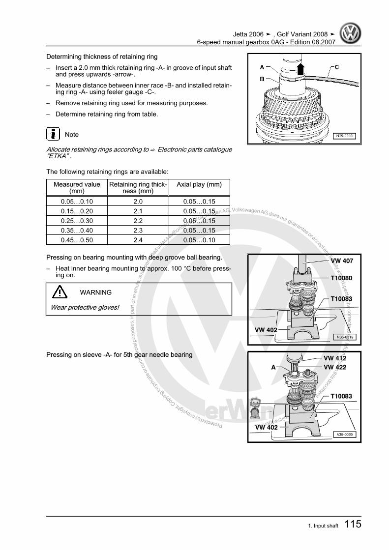
Protected by copyright. C
opying
for p
rivat
e or
com
mer
cial
pur
pose
s, in
par
t or i
n w
hole
, is
not p
erm
itted
unles
s authorise
d by Volkswagen AG. Volkswagen AG does not guarantee or accept any liability with respect to the correctness ofinform
ation in this document.Copyright by Volkswagen AG.
Determining thickness of retaining ring– Insert a 2.0 mm thick retaining ring -A- in groove of input shaft
and press upwards -arrow-.– Measure distance between inner race -B- and installed retain‐
ing ring -A- using feeler gauge -C-.– Remove retaining ring used for measuring purposes.– Determine retaining ring from table.
Note
Allocate retaining rings according to ⇒ Electronic parts catalogue“ETKA” .
The following retaining rings are available:
Measured value(mm)
Retaining ring thick‐ness (mm)
Axial play (mm)
0.05…0.10 2.0 0.05…0.150.15…0.20 2.1 0.05…0.150.25…0.30 2.2 0.05…0.150.35…0.40 2.3 0.05…0.150.45…0.50 2.4 0.05…0.10
Pressing on bearing mounting with deep groove ball bearing.– Heat inner bearing mounting to approx. 100 °C before press‐
ing on.
WARNING
Wear protective gloves!
Pressing on sleeve -A- for 5th gear needle bearing
Jetta 2006 ➤ , Golf Variant 2008 ➤6-speed manual gearbox 0AG - Edition 08.2007
1. Input shaft 115

Protected by copyright. C
opying
for p
rivat
e or
com
mer
cial
pur
pose
s, in
par
t or i
n w
hole
, is
not p
erm
itted
unles
s authorise
d by Volkswagen AG. Volkswagen AG does not guarantee or accept any liability with respect to the correctness ofinform
ation in this document.Copyright by Volkswagen AG.
Dismantling and assembling locking collar and synchro-hub for5th and 6th gear1 - Spring2 - Locking collar3 - Synchro-hub4 - Locking piece– Slide locking collar over synchro-hub.Deeper notches -arrow A- for locking pieces in synchro-hub andnotches -arrow B- in locking collar must align.
Assembling locking collar and synchro-hub for 5th and 6th gear• Locking collar has been pushed over synchro-hub.– Insert locking pieces in deeper notches -arrows- and install
springs offset 120°.• Angled end of spring must locate in hollow locking piece.
Jetta 2006 ➤ , Golf Variant 2008 ➤6-speed manual gearbox 0AG - Edition 08.2007
116 Rep. Gr.35 - Gears, shafts

Protected by copyright. C
opying
for p
rivat
e or
com
mer
cial
pur
pose
s, in
par
t or i
n w
hole
, is
not p
erm
itted
unles
s authorise
d by Volkswagen AG. Volkswagen AG does not guarantee or accept any liability with respect to the correctness ofinform
ation in this document.Copyright by Volkswagen AG.
2 Output shaft
2.1 Dismantling and assembling output shaft
Special tools and workshopequipment required♦ Thrust plate -VW 402-♦ Press tool -VW 407-♦ Tube -VW 415 A-♦ Thrust piece -VW 432-♦ Drift sleeve -30 - 100-
♦ Internal puller -1- Kukko 21/5-
♦ Counter support -4- Kukko 22/1-
Jetta 2006 ➤ , Golf Variant 2008 ➤6-speed manual gearbox 0AG - Edition 08.2007
2. Output shaft 117
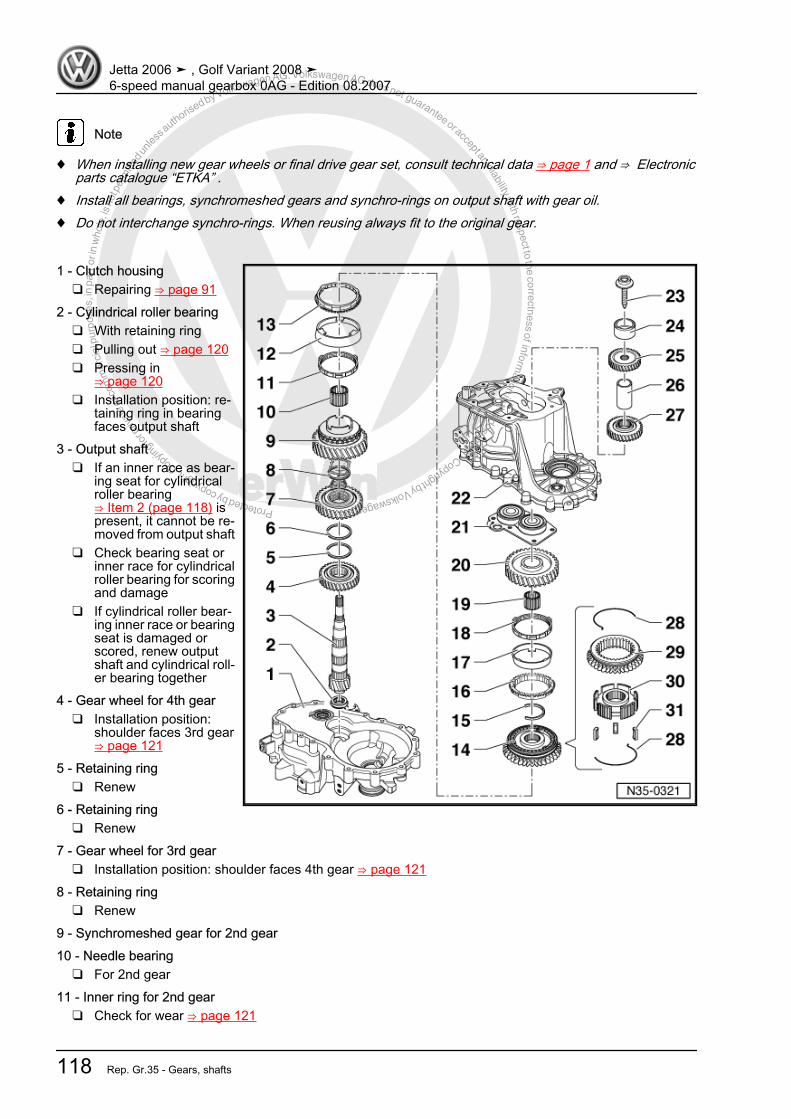
Protected by copyright. C
opying
for p
rivat
e or
com
mer
cial
pur
pose
s, in
par
t or i
n w
hole
, is
not p
erm
itted
unles
s authorise
d by Volkswagen AG. Volkswagen AG does not guarantee or accept any liability with respect to the correctness ofinform
ation in this document.Copyright by Volkswagen AG.
Note
♦ When installing new gear wheels or final drive gear set, consult technical data ⇒ page 1 and ⇒ Electronicparts catalogue “ETKA” .
♦ Install all bearings, synchromeshed gears and synchro-rings on output shaft with gear oil.♦ Do not interchange synchro-rings. When reusing always fit to the original gear.
1 - Clutch housing❑ Repairing ⇒ page 91
2 - Cylindrical roller bearing❑ With retaining ring❑ Pulling out ⇒ page 120❑ Pressing in
⇒ page 120❑ Installation position: re‐
taining ring in bearingfaces output shaft
3 - Output shaft❑ If an inner race as bear‐
ing seat for cylindricalroller bearing⇒ Item 2 (page 118) ispresent, it cannot be re‐moved from output shaft
❑ Check bearing seat orinner race for cylindricalroller bearing for scoringand damage
❑ If cylindrical roller bear‐ing inner race or bearingseat is damaged orscored, renew outputshaft and cylindrical roll‐er bearing together
4 - Gear wheel for 4th gear❑ Installation position:
shoulder faces 3rd gear⇒ page 121
5 - Retaining ring❑ Renew
6 - Retaining ring❑ Renew
7 - Gear wheel for 3rd gear❑ Installation position: shoulder faces 4th gear ⇒ page 121
8 - Retaining ring❑ Renew
9 - Synchromeshed gear for 2nd gear10 - Needle bearing
❑ For 2nd gear11 - Inner ring for 2nd gear
❑ Check for wear ⇒ page 121
Jetta 2006 ➤ , Golf Variant 2008 ➤6-speed manual gearbox 0AG - Edition 08.2007
118 Rep. Gr.35 - Gears, shafts

Protected by copyright. C
opying
for p
rivat
e or
com
mer
cial
pur
pose
s, in
par
t or i
n w
hole
, is
not p
erm
itted
unles
s authorise
d by Volkswagen AG. Volkswagen AG does not guarantee or accept any liability with respect to the correctness ofinform
ation in this document.Copyright by Volkswagen AG.
❑ Installation position ⇒ page 12212 - Outer ring for 2nd gear
❑ Place on inner ring ⇒ Item 11 (page 118) .❑ Renew if scored❑ Installation position ⇒ page 122
13 - Synchro-ring for 2nd gear❑ Check for wear ⇒ page 121❑ Installation position ⇒ page 122
14 - Locking collar with synchro-hub for 1st and 2nd gears❑ After removing retaining ring ⇒ Item 15 (page 119) , press off with 2nd gear synchromeshed gear
⇒ page 121❑ Dismantling ⇒ page 122❑ Assembling locking collar and synchro-hub ⇒ page 122 and ⇒ page 122❑ Installation position ⇒ page 122❑ Pressing on ⇒ page 123
15 - Retaining ring❑ Pressing out ⇒ page 120❑ Installing ⇒ page 123
16 - Synchro-ring for 1st gear❑ Check for wear ⇒ page 121❑ Assemble so that notches engage in locking pieces of locking collar ⇒ Item 14 (page 119)
17 - Outer ring for 1st gear❑ Insert in synchro-ring ⇒ Item 16 (page 119)❑ Installation position❑ Renew if scored
18 - Inner ring for 1st gear❑ Check for wear ⇒ page 121❑ Check lugs for scoring❑ Installation position ⇒ page 123
19 - Needle bearing❑ For 1st gear
20 - Synchromeshed gear for 1st gear❑ Installation position ⇒ page 124
21 - Bearing mounting with deep groove ball bearing❑ Renew deep groove ball bearing only together with bearing mounting❑ If bearing mounting is separated from gearbox housing, then mounting must always be renewed.❑ Pressing off ⇒ page 112❑ Pressing on ⇒ page 115
22 - Gearbox housing❑ Repairing ⇒ page 91
23 - Bolt❑ Removing and installing ⇒ page 74
24 - Cylindrical roller bearing inner race❑ Mark before removing❑ Do not interchange with cylindrical roller bearing inner race of input shaft❑ Can be renewed individually.❑ Removing and installing ⇒ page 78
Jetta 2006 ➤ , Golf Variant 2008 ➤6-speed manual gearbox 0AG - Edition 08.2007
2. Output shaft 119
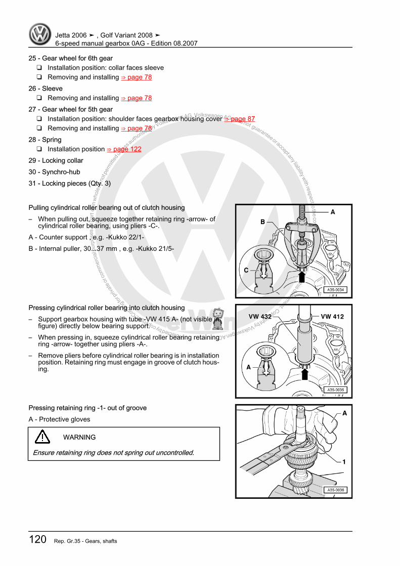
Protected by copyright. C
opying
for p
rivat
e or
com
mer
cial
pur
pose
s, in
par
t or i
n w
hole
, is
not p
erm
itted
unles
s authorise
d by Volkswagen AG. Volkswagen AG does not guarantee or accept any liability with respect to the correctness ofinform
ation in this document.Copyright by Volkswagen AG.
25 - Gear wheel for 6th gear❑ Installation position: collar faces sleeve❑ Removing and installing ⇒ page 78
26 - Sleeve❑ Removing and installing ⇒ page 78
27 - Gear wheel for 5th gear❑ Installation position: shoulder faces gearbox housing cover ⇒ page 87❑ Removing and installing ⇒ page 78
28 - Spring❑ Installation position ⇒ page 122
29 - Locking collar30 - Synchro-hub31 - Locking pieces (Qty. 3)
Pulling cylindrical roller bearing out of clutch housing– When pulling out, squeeze together retaining ring -arrow- of
cylindrical roller bearing, using pliers -C-.A - Counter support , e.g. -Kukko 22/1-B - Internal puller, 30...37 mm , e.g. -Kukko 21/5-
Pressing cylindrical roller bearing into clutch housing– Support gearbox housing with tube -VW 415 A- (not visible in
figure) directly below bearing support.– When pressing in, squeeze cylindrical roller bearing retaining
ring -arrow- together using pliers -A-.– Remove pliers before cylindrical roller bearing is in installation
position. Retaining ring must engage in groove of clutch hous‐ing.
Pressing retaining ring -1- out of grooveA - Protective gloves
WARNING
Ensure retaining ring does not spring out uncontrolled.
Jetta 2006 ➤ , Golf Variant 2008 ➤6-speed manual gearbox 0AG - Edition 08.2007
120 Rep. Gr.35 - Gears, shafts

Protected by copyright. C
opying
for p
rivat
e or
com
mer
cial
pur
pose
s, in
par
t or i
n w
hole
, is
not p
erm
itted
unles
s authorise
d by Volkswagen AG. Volkswagen AG does not guarantee or accept any liability with respect to the correctness ofinform
ation in this document.Copyright by Volkswagen AG.
Pressing off 1st and 2nd gear locking collar and synchro-hub– After removing retaining ring, press off synchromeshed gear
for 2nd gear together with locking collar and synchro-hub.
Installation position of 3rd gear and 4th gear– Install 4th gear wheel -A- on output shaft.Installation position:Collar -arrow 1- faces 3rd gear wheel -B-.– Install retaining rings -2- and -3-.– Install 3rd gear wheel -B- on output shaft.Installation position:Collar -arrow 2- faces 4th gear wheel -A-.– Install retaining ring -1-.
Checking 1st and 2nd gear inner ring for wear– Press inner ring onto cone of synchromeshed gear and meas‐
ure gap -a- using a feeler gauge.
Gap -a- Installation (new) di‐mension
Wear limit
1st and 2nd gears 0.75…1.25 mm 0.3 mm
Checking 1st and 2nd gear synchro-rings for wear– Press synchro-ring, outer ring and inner ring onto cone of syn‐
chromeshed gear and measure gap -a- using a feeler gauge.
Gap -a- Installation (new) di‐mension
Wear limit
1st and 2nd gears 1.2…1.8 mm 0.5 mm
Jetta 2006 ➤ , Golf Variant 2008 ➤6-speed manual gearbox 0AG - Edition 08.2007
2. Output shaft 121
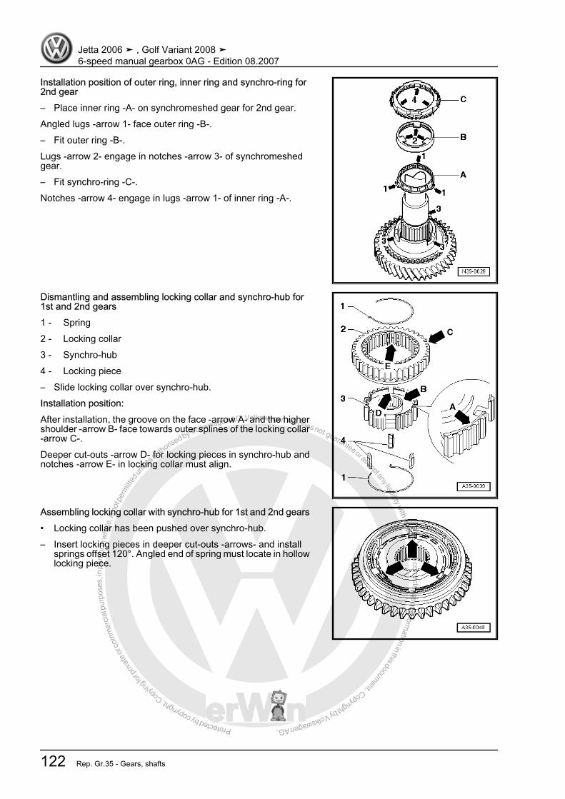
Protected by copyright. C
opying
for p
rivat
e or
com
mer
cial
pur
pose
s, in
par
t or i
n w
hole
, is
not p
erm
itted
unles
s authorise
d by Volkswagen AG. Volkswagen AG does not guarantee or accept any liability with respect to the correctness ofinform
ation in this document.Copyright by Volkswagen AG.
Installation position of outer ring, inner ring and synchro-ring for2nd gear– Place inner ring -A- on synchromeshed gear for 2nd gear.Angled lugs -arrow 1- face outer ring -B-.– Fit outer ring -B-.Lugs -arrow 2- engage in notches -arrow 3- of synchromeshedgear.– Fit synchro-ring -C-.Notches -arrow 4- engage in lugs -arrow 1- of inner ring -A-.
Dismantling and assembling locking collar and synchro-hub for1st and 2nd gears1 - Spring2 - Locking collar3 - Synchro-hub4 - Locking piece– Slide locking collar over synchro-hub.Installation position:After installation, the groove on the face -arrow A- and the highershoulder -arrow B- face towards outer splines of the locking collar-arrow C-.Deeper cut-outs -arrow D- for locking pieces in synchro-hub andnotches -arrow E- in locking collar must align.
Assembling locking collar with synchro-hub for 1st and 2nd gears• Locking collar has been pushed over synchro-hub.– Insert locking pieces in deeper cut-outs -arrows- and install
springs offset 120°. Angled end of spring must locate in hollowlocking piece.
Jetta 2006 ➤ , Golf Variant 2008 ➤6-speed manual gearbox 0AG - Edition 08.2007
122 Rep. Gr.35 - Gears, shafts

Protected by copyright. C
opying
for p
rivat
e or
com
mer
cial
pur
pose
s, in
par
t or i
n w
hole
, is
not p
erm
itted
unles
s authorise
d by Volkswagen AG. Volkswagen AG does not guarantee or accept any liability with respect to the correctness ofinform
ation in this document.Copyright by Volkswagen AG.
Pressing on locking collar and synchro-hub for 1st and 2nd gearsInstallation position:Groove in locking collar for selector fork faces 1st gear and teethfor reverse gear face 2nd gear.– Turn synchro-ring so that grooves align with locking pieces.
Fitting retaining ring– Place 1st gear synchro-ring in locking collar/synchro-hub.
Installation position of 1st gear outer ringLugs -arrows- face reverse gear teeth.
Installation position of 1st gear -A-Lugs -arrow 1- engage in notches -arrow 2- in synchro-ring -B-.
Jetta 2006 ➤ , Golf Variant 2008 ➤6-speed manual gearbox 0AG - Edition 08.2007
2. Output shaft 123

Protected by copyright. C
opying
for p
rivat
e or
com
mer
cial
pur
pose
s, in
par
t or i
n w
hole
, is
not p
erm
itted
unles
s authorise
d by Volkswagen AG. Volkswagen AG does not guarantee or accept any liability with respect to the correctness ofinform
ation in this document.Copyright by Volkswagen AG.
Installation position of 1st gear synchromeshed gearHigher shoulder -A- faces 2nd gear -B-. Notches in shoulder-arrows- engage in lugs of outer ring ⇒ page 123 .
Jetta 2006 ➤ , Golf Variant 2008 ➤6-speed manual gearbox 0AG - Edition 08.2007
124 Rep. Gr.35 - Gears, shafts
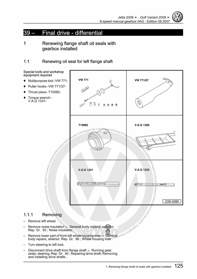
Protected by copyright. C
opying
for p
rivat
e or
com
mer
cial
pur
pose
s, in
par
t or i
n w
hole
, is
not p
erm
itted
unles
s authorise
d by Volkswagen AG. Volkswagen AG does not guarantee or accept any liability with respect to the correctness ofinform
ation in this document.Copyright by Volkswagen AG.
39 – Final drive - differential1 Renewing flange shaft oil seals with
gearbox installed
1.1 Renewing oil seal for left flange shaft
Special tools and workshopequipment required♦ Multipurpose tool -VW 771-♦ Puller hooks -VW 771/37-♦ Thrust piece -T10082-♦ Torque wrench -
V.A.G 1331-
1.1.1 Removing– Remove left wheel.– Remove noise insulation ⇒ General body repairs, exterior;
Rep. Gr. 50 ; Noise insulation .– Remove lower part of front left wheel housing liner ⇒ General
body repairs, exterior; Rep. Gr. 66 ; Wheel housing liner .– Turn steering to left lock.– Disconnect drive shaft from flange shaft ⇒ Running gear,
axles, steering; Rep. Gr. 40 ; Repairing drive shaft; Removingand installing drive shafts .
Jetta 2006 ➤ , Golf Variant 2008 ➤6-speed manual gearbox 0AG - Edition 08.2007
1. Renewing flange shaft oil seals with gearbox installed 125
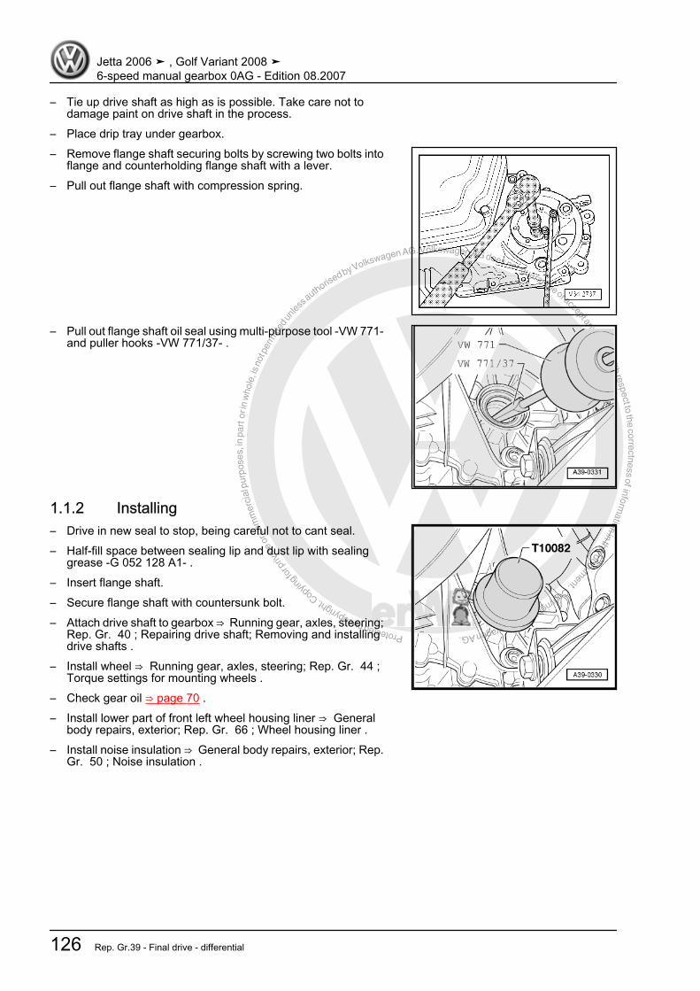
Protected by copyright. C
opying
for p
rivat
e or
com
mer
cial
pur
pose
s, in
par
t or i
n w
hole
, is
not p
erm
itted
unles
s authorise
d by Volkswagen AG. Volkswagen AG does not guarantee or accept any liability with respect to the correctness ofinform
ation in this document.Copyright by Volkswagen AG.
– Tie up drive shaft as high as is possible. Take care not todamage paint on drive shaft in the process.
– Place drip tray under gearbox.– Remove flange shaft securing bolts by screwing two bolts into
flange and counterholding flange shaft with a lever.– Pull out flange shaft with compression spring.
– Pull out flange shaft oil seal using multi-purpose tool -VW 771-and puller hooks -VW 771/37- .
1.1.2 Installing– Drive in new seal to stop, being careful not to cant seal.– Half-fill space between sealing lip and dust lip with sealing
grease -G 052 128 A1- .– Insert flange shaft.– Secure flange shaft with countersunk bolt.– Attach drive shaft to gearbox ⇒ Running gear, axles, steering;
Rep. Gr. 40 ; Repairing drive shaft; Removing and installingdrive shafts .
– Install wheel ⇒ Running gear, axles, steering; Rep. Gr. 44 ;Torque settings for mounting wheels .
– Check gear oil ⇒ page 70 .– Install lower part of front left wheel housing liner ⇒ General
body repairs, exterior; Rep. Gr. 66 ; Wheel housing liner .– Install noise insulation ⇒ General body repairs, exterior; Rep.
Gr. 50 ; Noise insulation .
Jetta 2006 ➤ , Golf Variant 2008 ➤6-speed manual gearbox 0AG - Edition 08.2007
126 Rep. Gr.39 - Final drive - differential

Protected by copyright. C
opying
for p
rivat
e or
com
mer
cial
pur
pose
s, in
par
t or i
n w
hole
, is
not p
erm
itted
unles
s authorise
d by Volkswagen AG. Volkswagen AG does not guarantee or accept any liability with respect to the correctness ofinform
ation in this document.Copyright by Volkswagen AG.
1.1.3 Torque settingsFlange shaft to gearbox (countersunk bolt) 25 Nm
1.2 Renewing seal for right flange shaft
Special tools and workshop equipment required♦ Multipurpose tool -VW 771-♦ Puller hooks -VW 771/37-♦ Drift sleeve -3158-♦ Torque wrench -V.A.G 1331-
1.2.1 Removing– Remove noise insulation ⇒ General body repairs, exterior;
Rep. Gr. 50 ; Noise insulation .– Turn steering to right to full lock.
Jetta 2006 ➤ , Golf Variant 2008 ➤6-speed manual gearbox 0AG - Edition 08.2007
1. Renewing flange shaft oil seals with gearbox installed 127
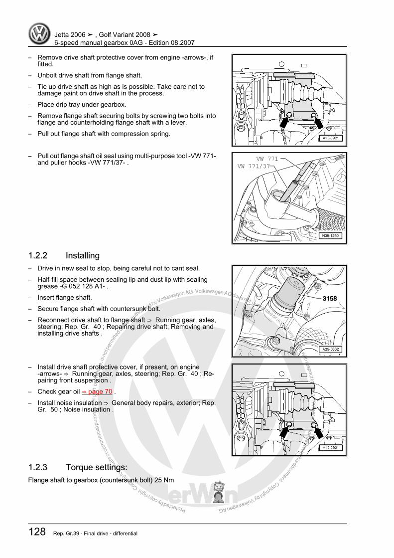
Protected by copyright. C
opying
for p
rivat
e or
com
mer
cial
pur
pose
s, in
par
t or i
n w
hole
, is
not p
erm
itted
unles
s authorise
d by Volkswagen AG. Volkswagen AG does not guarantee or accept any liability with respect to the correctness ofinform
ation in this document.Copyright by Volkswagen AG.
– Remove drive shaft protective cover from engine -arrows-, iffitted.
– Unbolt drive shaft from flange shaft.– Tie up drive shaft as high as is possible. Take care not to
damage paint on drive shaft in the process.– Place drip tray under gearbox.– Remove flange shaft securing bolts by screwing two bolts into
flange and counterholding flange shaft with a lever.– Pull out flange shaft with compression spring.
– Pull out flange shaft oil seal using multi-purpose tool -VW 771-and puller hooks -VW 771/37- .
1.2.2 Installing– Drive in new seal to stop, being careful not to cant seal.– Half-fill space between sealing lip and dust lip with sealing
grease -G 052 128 A1- .– Insert flange shaft.– Secure flange shaft with countersunk bolt.– Reconnect drive shaft to flange shaft ⇒ Running gear, axles,
steering; Rep. Gr. 40 ; Repairing drive shaft; Removing andinstalling drive shafts .
– Install drive shaft protective cover, if present, on engine-arrows- ⇒ Running gear, axles, steering; Rep. Gr. 40 ; Re‐pairing front suspension .
– Check gear oil ⇒ page 70 .– Install noise insulation ⇒ General body repairs, exterior; Rep.
Gr. 50 ; Noise insulation .
1.2.3 Torque settings:Flange shaft to gearbox (countersunk bolt) 25 Nm
Jetta 2006 ➤ , Golf Variant 2008 ➤6-speed manual gearbox 0AG - Edition 08.2007
128 Rep. Gr.39 - Final drive - differential
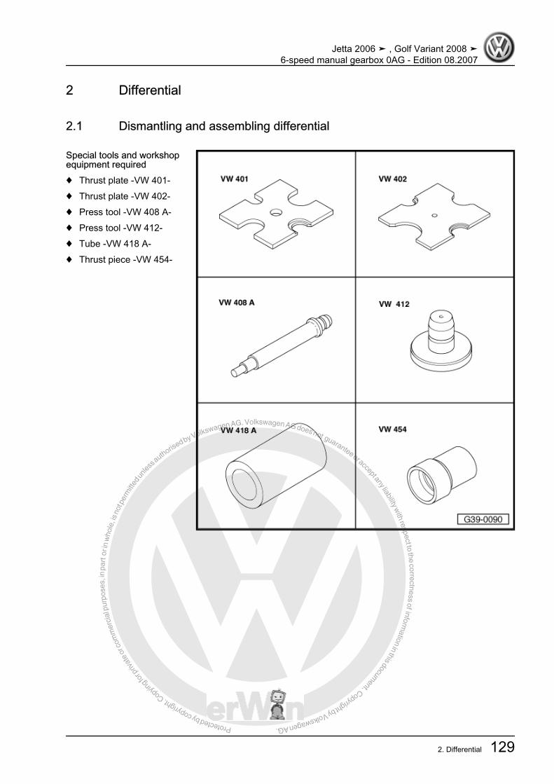
Protected by copyright. C
opying
for p
rivat
e or
com
mer
cial
pur
pose
s, in
par
t or i
n w
hole
, is
not p
erm
itted
unles
s authorise
d by Volkswagen AG. Volkswagen AG does not guarantee or accept any liability with respect to the correctness ofinform
ation in this document.Copyright by Volkswagen AG.
2 Differential
2.1 Dismantling and assembling differential
Special tools and workshopequipment required♦ Thrust plate -VW 401-♦ Thrust plate -VW 402-♦ Press tool -VW 408 A-♦ Press tool -VW 412-♦ Tube -VW 418 A-♦ Thrust piece -VW 454-
Jetta 2006 ➤ , Golf Variant 2008 ➤6-speed manual gearbox 0AG - Edition 08.2007
2. Differential 129

Protected by copyright. C
opying
for p
rivat
e or
com
mer
cial
pur
pose
s, in
par
t or i
n w
hole
, is
not p
erm
itted
unles
s authorise
d by Volkswagen AG. Volkswagen AG does not guarantee or accept any liability with respect to the correctness ofinform
ation in this document.Copyright by Volkswagen AG.
♦ Installing sleeve -VW 455-♦ Spacer sleeve -VW 472/2-♦ Thrust pad -VW 510-♦ Tube -30 - 14-♦ Tube -2040-♦ Thrust piece -3002-
Jetta 2006 ➤ , Golf Variant 2008 ➤6-speed manual gearbox 0AG - Edition 08.2007
130 Rep. Gr.39 - Final drive - differential
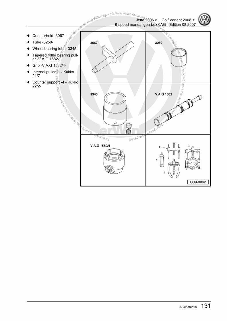
Protected by copyright. C
opying
for p
rivat
e or
com
mer
cial
pur
pose
s, in
par
t or i
n w
hole
, is
not p
erm
itted
unles
s authorise
d by Volkswagen AG. Volkswagen AG does not guarantee or accept any liability with respect to the correctness ofinform
ation in this document.Copyright by Volkswagen AG.
♦ Counterhold -3067-♦ Tube -3259-♦ Wheel bearing tube -3345-♦ Tapered roller bearing pull‐
er -V.A.G 1582-♦ Grip -V.A.G 1582/4-♦ Internal puller -1 - Kukko
21/7-♦ Counter support -4 - Kukko
22/2-
Jetta 2006 ➤ , Golf Variant 2008 ➤6-speed manual gearbox 0AG - Edition 08.2007
2. Differential 131

Protected by copyright. C
opying
for p
rivat
e or
com
mer
cial
pur
pose
s, in
par
t or i
n w
hole
, is
not p
erm
itted
unles
s authorise
d by Volkswagen AG. Volkswagen AG does not guarantee or accept any liability with respect to the correctness ofinform
ation in this document.Copyright by Volkswagen AG.
♦ Thrust plate -30 - 205-♦ Drift sleeve -40 - 21-♦ Torque wrench -
V.A.G 1331- (5 ... 50 Nm)♦ Grip -V.A.G 1582/3-
Note
♦ Heat tapered roller bearing inner race to 100° C before installing.♦ Always renew both tapered roller bearings together as a set.♦ If tapered roller bearings, differential cage, gearbox housing or clutch housing is renewed, adjust differential
⇒ page 137 .
Jetta 2006 ➤ , Golf Variant 2008 ➤6-speed manual gearbox 0AG - Edition 08.2007
132 Rep. Gr.39 - Final drive - differential

Protected by copyright. C
opying
for p
rivat
e or
com
mer
cial
pur
pose
s, in
par
t or i
n w
hole
, is
not p
erm
itted
unles
s authorise
d by Volkswagen AG. Volkswagen AG does not guarantee or accept any liability with respect to the correctness ofinform
ation in this document.Copyright by Volkswagen AG.
1 - Countersunk bolt, 25 Nm❑ Screw into threaded
piece⇒ Item 8 (page 133)
2 - Right flange shaft3 - Compression spring forflange shaft
❑ Installed behind flangeshafts
4 - Thrust washer❑ Installation position:
shoulder towards spring5 - Tapered ring
❑ Installation position:taper towards differen‐tial cage
6 - Retaining ring❑ Holds tapered ring,
thrust washer andspring in position whenflange shaft is removed
7 - Sun wheel❑ Installing ⇒ page 136
8 - Threaded piece❑ Installing ⇒ page 136
9 - Differential pinion pin❑ To remove, shear off
spring pin⇒ Item 18 (page 134)⇒ page 136
❑ Installing ⇒ page 13610 - Planet pinion
❑ Installing ⇒ page 13611 - One-piece thrust washer
❑ Coat with gear oil when installing12 - Left flange shaft13 - Oil seal for left flange shaft
❑ Renewing with manual gearbox installed ⇒ page 125 .14 - Shim S1
❑ For differential❑ Always 1 mm thick❑ Shim S1 discontinued as of gearbox date 04 12 6 ⇒ page 139❑ Bearing seat for tapered roller bearing outer race adapted in gearbox housing❑ Allocation ⇒ Electronic parts catalogue (ETKA)
15 - Tapered roller bearing outer race❑ Pulling out ⇒ page 134❑ Pressing in ⇒ page 134
16 - Tapered roller bearing inner race❑ Pulling off ⇒ page 135❑ Pressing on ⇒ page 135
Jetta 2006 ➤ , Golf Variant 2008 ➤6-speed manual gearbox 0AG - Edition 08.2007
2. Differential 133
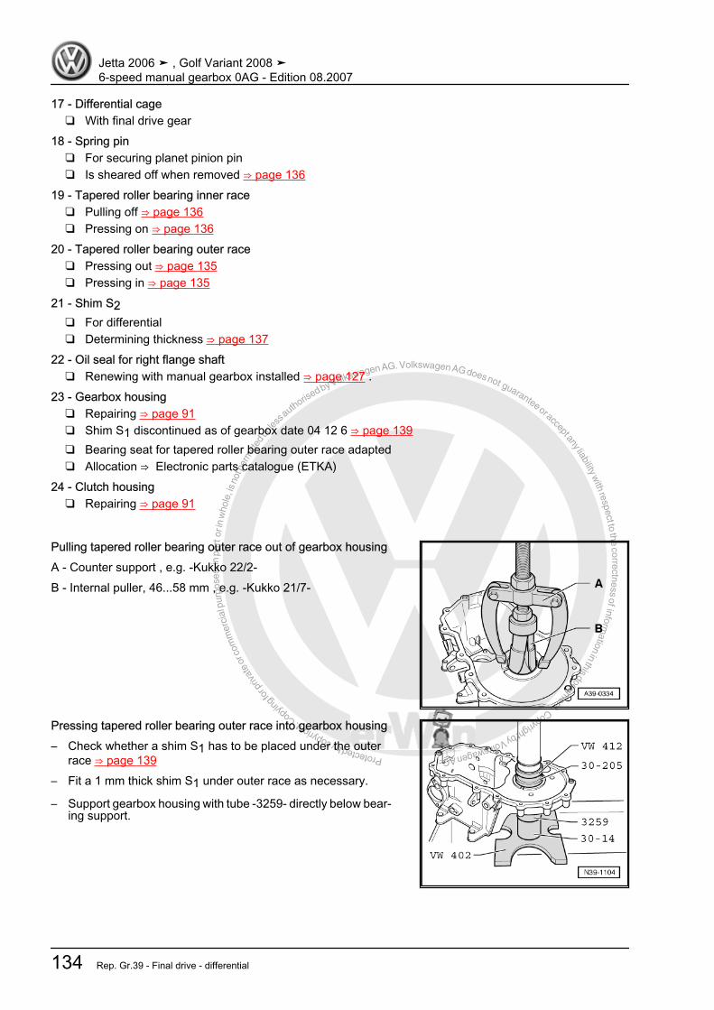
Protected by copyright. C
opying
for p
rivat
e or
com
mer
cial
pur
pose
s, in
par
t or i
n w
hole
, is
not p
erm
itted
unles
s authorise
d by Volkswagen AG. Volkswagen AG does not guarantee or accept any liability with respect to the correctness ofinform
ation in this document.Copyright by Volkswagen AG.
17 - Differential cage❑ With final drive gear
18 - Spring pin❑ For securing planet pinion pin❑ Is sheared off when removed ⇒ page 136
19 - Tapered roller bearing inner race❑ Pulling off ⇒ page 136❑ Pressing on ⇒ page 136
20 - Tapered roller bearing outer race❑ Pressing out ⇒ page 135❑ Pressing in ⇒ page 135
21 - Shim S2❑ For differential❑ Determining thickness ⇒ page 137
22 - Oil seal for right flange shaft❑ Renewing with manual gearbox installed ⇒ page 127 .
23 - Gearbox housing❑ Repairing ⇒ page 91❑ Shim S1 discontinued as of gearbox date 04 12 6 ⇒ page 139❑ Bearing seat for tapered roller bearing outer race adapted❑ Allocation ⇒ Electronic parts catalogue (ETKA)
24 - Clutch housing❑ Repairing ⇒ page 91
Pulling tapered roller bearing outer race out of gearbox housingA - Counter support , e.g. -Kukko 22/2-B - Internal puller, 46...58 mm , e.g. -Kukko 21/7-
Pressing tapered roller bearing outer race into gearbox housing– Check whether a shim S1 has to be placed under the outer
race ⇒ page 139– Fit a 1 mm thick shim S1 under outer race as necessary.
– Support gearbox housing with tube -3259- directly below bear‐ing support.
Jetta 2006 ➤ , Golf Variant 2008 ➤6-speed manual gearbox 0AG - Edition 08.2007
134 Rep. Gr.39 - Final drive - differential

Protected by copyright. C
opying
for p
rivat
e or
com
mer
cial
pur
pose
s, in
par
t or i
n w
hole
, is
not p
erm
itted
unles
s authorise
d by Volkswagen AG. Volkswagen AG does not guarantee or accept any liability with respect to the correctness ofinform
ation in this document.Copyright by Volkswagen AG.
Pulling off tapered roller bearing inner races
Note
Both tapered roller bearing inner races are pulled off the differ‐ential cage in the same way.
Pressing on tapered roller bearing inner race
WARNING
Wear protective gloves!
– Heat inner tapered roller bearing race to approx. 100 °C beforepressing on.
– Support inner race on opposite side using installing sleeve -VW 455- .
Shoulder of sleeve -VW 455- faces towards differential cage.
Pressing tapered roller bearing outer race -A- out of clutch hous‐ingB - Internal puller, 46...58 mm , e.g. -Kukko 21/7-– Clamp internal puller securely behind tapered roller bearing
outer race.
Pressing tapered roller bearing outer race into clutch housing– Support clutch housing with wheel bearing tube -3345- directly
below bearing mounting.
Jetta 2006 ➤ , Golf Variant 2008 ➤6-speed manual gearbox 0AG - Edition 08.2007
2. Differential 135
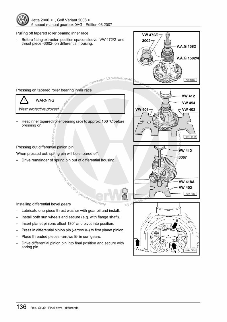
Protected by copyright. C
opying
for p
rivat
e or
com
mer
cial
pur
pose
s, in
par
t or i
n w
hole
, is
not p
erm
itted
unles
s authorise
d by Volkswagen AG. Volkswagen AG does not guarantee or accept any liability with respect to the correctness ofinform
ation in this document.Copyright by Volkswagen AG.
Pulling off tapered roller bearing inner race– Before fitting extractor, position spacer sleeve -VW 472/2- and
thrust piece -3002- on differential housing.
Pressing on tapered roller bearing inner race
WARNING
Wear protective gloves!
– Heat inner tapered roller bearing race to approx. 100 °C beforepressing on.
Pressing out differential pinion pinWhen pressed out, spring pin will be sheared off.– Drive remainder of spring pin out of differential housing.
Installing differential bevel gears– Lubricate one-piece thrust washer with gear oil and install.– Install both sun wheels and secure (e.g. with flange shaft).– Insert planet pinions offset 180° and pivot into position.– Press in differential pinion pin (-arrow A-) to first planet pinion.– Place threaded pieces -arrows B- in sun gears.– Drive differential pinion pin into final position and secure with
spring pin.
Jetta 2006 ➤ , Golf Variant 2008 ➤6-speed manual gearbox 0AG - Edition 08.2007
136 Rep. Gr.39 - Final drive - differential
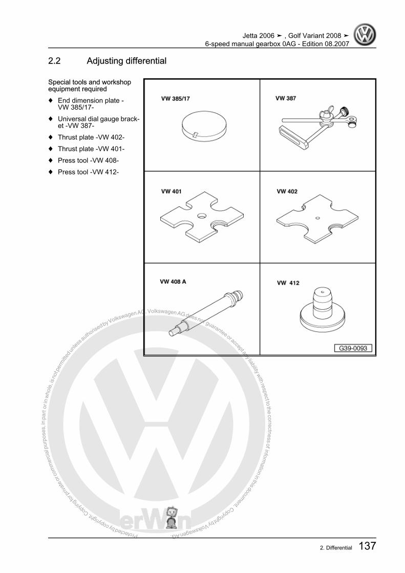
Protected by copyright. C
opying
for p
rivat
e or
com
mer
cial
pur
pose
s, in
par
t or i
n w
hole
, is
not p
erm
itted
unles
s authorise
d by Volkswagen AG. Volkswagen AG does not guarantee or accept any liability with respect to the correctness ofinform
ation in this document.Copyright by Volkswagen AG.
2.2 Adjusting differential
Special tools and workshopequipment required♦ End dimension plate -
VW 385/17-♦ Universal dial gauge brack‐
et -VW 387-♦ Thrust plate -VW 402-♦ Thrust plate -VW 401-♦ Press tool -VW 408-♦ Press tool -VW 412-
Jetta 2006 ➤ , Golf Variant 2008 ➤6-speed manual gearbox 0AG - Edition 08.2007
2. Differential 137

Protected by copyright. C
opying
for p
rivat
e or
com
mer
cial
pur
pose
s, in
par
t or i
n w
hole
, is
not p
erm
itted
unles
s authorise
d by Volkswagen AG. Volkswagen AG does not guarantee or accept any liability with respect to the correctness ofinform
ation in this document.Copyright by Volkswagen AG.
♦ Thrust pad -VW 510-♦ Tube -30 - 14-♦ Tube -2040-♦ Tube -3259-♦ Wheel bearing tube -3345-♦ Torque wrench -
V.A.G 1331-♦ Dial gauge
♦ Thrust plate -30 - 205-
It is necessary to readjust the differential when the following com‐ponents are renewed:♦ Gearbox housing♦ Clutch housing♦ Differential cageor the
Jetta 2006 ➤ , Golf Variant 2008 ➤6-speed manual gearbox 0AG - Edition 08.2007
138 Rep. Gr.39 - Final drive - differential

Protected by copyright. C
opying
for p
rivat
e or
com
mer
cial
pur
pose
s, in
par
t or i
n w
hole
, is
not p
erm
itted
unles
s authorise
d by Volkswagen AG. Volkswagen AG does not guarantee or accept any liability with respect to the correctness ofinform
ation in this document.Copyright by Volkswagen AG.
♦ Tapered roller bearings of differentialShim S1 for the tapered roller bearing outer race has been dis‐continued as of gearbox date 04 12 6.Bearing seat for tapered roller bearing outer race adapted– Measure the depth of the bearing seat for tapered roller bear‐
ing outer race in gearbox housing
Dimension “a” Shim S115.2 mm no16.2 mm yes
Continuation for all
– Press tapered roller bearing outer race (gear wheel side) withshim S1 (always 1 mm thick) into the gearbox housing.
Note
Inner and outer tapered roller bearing races are paired. Do notinterchange!
– Press tapered roller bearing outer race (opposite gear wheel)with no shim into gearbox housing.
– Insert differential in gearbox housing.– Fit clutch housing and tighten 5 bolts to specified torque
⇒ page 76 .
– Attach dial gauge and set to “0” with 1 mm preload.A - 30 mm dial gauge extension– Set dial gauge to “0” with 1 mm preload.– Move differential up and down. Read and note play indicated
on dial gauge. (Example: 1.50 mm)
2.2.1 Determining shim S2The specified bearing preload is obtained for S2 by adding a con‐stant value for preload (0.35 mm) to the measured value.Example:
Measured value 1.50 mm
Jetta 2006 ➤ , Golf Variant 2008 ➤6-speed manual gearbox 0AG - Edition 08.2007
2. Differential 139

Protected by copyright. C
opying
for p
rivat
e or
com
mer
cial
pur
pose
s, in
par
t or i
n w
hole
, is
not p
erm
itted
unles
s authorise
d by Volkswagen AG. Volkswagen AG does not guarantee or accept any liability with respect to the correctness ofinform
ation in this document.Copyright by Volkswagen AG.
+ Preload (constant) 0.35 mmThickness of shim S2 = 1.85 mm
– Remove clutch housing and press out tapered roller bearingouter race -A-.
B - Internal puller, 46...58 mm , e.g. -Kukko 21/7-– Allocate shim(s) using ⇒ Electronic parts catalogue “ETKA” .The various thicknesses make it possible to achieve the exactshim thickness required.If the size of shim required is larger than those listed in the ⇒ Electronic parts catalogue “ETKA” , insert two shims totalling thecorrect figure.– Insert correct S2 shim (in example 1.85 mm) and press ta‐
pered roller bearing outer race into clutch housing again.– Fit clutch housing and tighten bolts to specified torque setting
⇒ page 76 .
Jetta 2006 ➤ , Golf Variant 2008 ➤6-speed manual gearbox 0AG - Edition 08.2007
140 Rep. Gr.39 - Final drive - differential