6. future potential - manchester
TRANSCRIPT

AGMA Decentralised and zero carbon energy planning study 62
6. Future potential
In this section we explore the future potential for a range of low and zero carbon energy sources as they apply to the City Region, and the infrastructure that would be required
to realise the potential.
To aid in understanding the different types of low and zero carbon energy technologies available
we begin by identifying broad categories and grouping them based on their strategic planning
implications. These include technologies that currently have sub regional targets for deployment
in the North West RSS.
In the following sections we take each technology in turn, with a focus on those we have
identified as having significant planning implications. For each technology we identify their broad
characteristics, and discuss the opportunities and the constraints to their implementation across
the City Region.
Where required spatial mapping has been carried out in order to explore the implications for land
use planning and infrastructure. This includes City Region scale mapping of wind energy
opportunities and analysis of site-specific opportunities relating to the use of waste heat from
decentralised generators.
6.1 Technologies and their planning implications
The technologies identified have the potential to provide heat, power and cooling, with a number
being distinctive to the City Region and/or representing newly discovered energy resources.
They can be grouped into five broad categories:
Networked heat and power generation: The use of decentralised Combined Heat and
Power (CHP) generators and heat-only boilers using a range of different fuels to supply
district heating and cooling networks linking together buildings;
Networked heating and cooling: The use of different grades of renewable heat from
surface and geothermal water resources to supply district heating and cooling networks
linking together buildings;
Standalone electricity generation: The use of renewable energy resources, such as the
wind and hydro resources, to generate electricity;
Renewable fuel supply chain: The production of a range of biofuels including chips,
pellets and oils from sources including forestry, energy crops, industrial and municipal
organic waste, biotechnology and carbon capture;
Building integrated heating, power and cooling: The use of ‘micro-generation’
technologies including solar thermal, solar photovoltaics, bio fuelled boilers and heat
pumps to supply individual buildings;

63
Our broad assessment for these technologies is intended to form an initial ‘top down’ evidence
base for opportunities across the City Region – albeit in outline because of limitations on the
scope of this study. We then make the link with their potential to deliver CO2 reduction for new
development is then explored in the ‘bottom up’ case study evidence base.
The scope of this section is by its nature broader than the sub regional allocations set out in the
current North West RSS. This is because we have sought to identify and characterise the full
range of technologies available to provide low and zero carbon energy supplies, reflecting the
priorities in the UK’s Low carbon transition plan, the 2007 Energy White Paper and the draft
Renewable Energy Strategy.
Figure 6.1
Technologies and their planning implications
Significant implications relating to utility infrastructure and siting
Networked heat and power generation
Combined Heat and Power (CHP): Small to medium-scale power generation (1-50 MWe)
supplying district heating networks. These plant could run on natural gas or make use of a
range of different renewable fuels (see below);
Combined Heat and Power (CHP): National Grid-scale power generation (up to 800 MWe)
supplying industrial steam and primary heat distribution pipelines. These plant would be
more likely to be gas-fired.
Networked heating and cooling
Biofuels: Dedicated boiler plant running on biofuels – both solid and liquid – in order to supply
district heating networks;
Geothermal: Heating and cooling loops drawing water from shallow boreholes, deep
boreholes, or from mine water where the configuration of old workings supports heat
transfer, supplying district heating;
Wastewater: District and neighbourhood refrigerant loops routed through the sewer network
or associated with treatment works, in order to supply district heating networks;
Significant implications relating to landscape character
Standalone electricity generation
Wind: Large-scale farms or clusters of 1-3 MWe turbines located in areas with a strategic
wind resource greater than 6.0-6.5 metres/second;
AGMA Decentralised and zero carbon energy planning study 64
Specific implications relating to siting and transport
Standalone gas production
Biogas: Medium to large-scale production of quality assured gas derived from biogas for
injection into the gas network.
Standalone electricity generation
Hydro: Small-scale 50-250 kWe turbines located in areas with a sufficient head of water.
Renewable fuel supply chain
Mixed municipal waste: Use of mixed waste or Refuse Derived Fuel (RDF) in specified heat
and power plant;
Waste-derived biogas: Methane for gas production or CHP generation produced from landfill
gas;
Forestry-derived biomass fuel: Wood chips and pellets manufactured from managed forestry
and municipal parks, gardens and tree surgery residue;
Waste-wood derived biomass fuel: Wood chips and pellets manufactured from industry-
derived waste wood;
Industry derived biomass fuel: Pellets and fuel oils manufactured from waste oil and,
potentially, algae from CO2 capture
Hydrogen: Gas produced by splitting water using renewable electricity, or by reforming
natural gas or biogas.
Permitted Development or subject to local environmental regulation
Building integrated heating, power and cooling
Solar: Heat and power generation from modules integrated into the roofs and facades of
buildings.
Heat pumps: Upgrading of heat sources that including gardens, car parks, waste courses
and wastewater in order to supply heating systems.
Biofuels: Heating supplied from boilers burning bio fuels that could include biomass and bio-
oils.
Canal cooling: Small clusters of heating/cooling requirements located on the canal network
(<1 MWth) supplying buildings.

65
6.2 Networked heat and power generation
In this section we describe the strategic opportunities for the development of medium to large-
scale Combined Heat and Power (CHP) generation supplying district heating networks, with the
potential to make use of a range of fuels.
6.2.1 Combined Heat and Power (CHP) technology
CHP is a proven technology which has the greatest potential to reduce CO2 emissions in mixed
use, city centre locations. This is because of their high density of development and mix of uses,
which create a diversified daytime heat demand profile.
This study considers the potential to utilise gas-fired, biomass, biogas and energy from waste-
fired CHP – technologies that each have separate and very different implementation issues
which are discussed in separate parts of this Section. What is common to all of them is the
need for a district heating network to supply the heat to end-users.
Technology profile
The benefits of CHP are based on that fact that generating electricity using conventional coal, oil
and nuclear power stations is inefficient, with over 60-70% of the energy being wasted. The
most efficient modern CHP systems use engines, turbines and fuel cells to generate electricity,
producing heat as a by-product that can then be distributed via a district heating system to local
consumers.
By utilising the waste heat the fuel efficiency of power generation improves from, on average
around 35%, to between 80% and 90%. Natural gas fired CHP supplying mixed use
developments with a balanced energy load profile delivers corresponding reductions in CO2
emissions of between 10% and 30% depending the scale of the CHP plant and the energy
demand profile of the buildings.
Further emissions reductions can be achieved by using natural gas in fuel cell CHP units. Fuel
cells are chemical engines with no moving parts, in which hydrogen gas is split in order to
generate an electrical current and waste heat. Hydrogen can be extracted from natural gas,
allowing the emissions from natural gas CHP to be halved.
Biofuelled CHP enables high levels of CO2 reductions to be realised because it enables both
heat and power to be generated using a carbon neutral fuel. There are a range of biofuel
options that are relevant to this study:
Biomass: Solid wood fuels derived from forestry, municipal parks and garden, and
dedicated energy crops such as coppiced willow;
Bio-oils: Crop-derived oils such as oil seed rape or food waste derived vegetable oils
from food processing;
Energy from Waste: Combustion of mixed waste or a Refuse Derived Fuel manufactured
from processed waste;

AGMA Decentralised and zero carbon energy planning study 66
Biogas: Methane gas from the anaerobic digestion of organic waste from a range of
different sources.
Landfill gas: Methane gas from the decomposition of organic waste in landfill sites.
Under the Government’s current definition many of these would qualify as being a ‘zero carbon’
source of energy. The majority of the solid and liquid biofuels are of a low grade and therefore
tend to require larger plant to make them economic to burn.
Track record in the UK
In the UK the image of CHP and district heating has suffered from the legacy of the 1960’s and
70’s when poor quality systems were installed on large new housing estates and mixed-use
developments. The CHP industry has now matured and the technology has advanced
significantly off the back of the experience and investment in mainland Europe.
There are a number of large CHP and district heating schemes in the UK. Most of these have
grown from heating systems supplied by energy from waste incinerators. These were used to
supply cheap base load heat to public buildings and large council housing estates – such as in
Sheffield and Nottingham.
In the 1990’s and 2000’s gas engine and turbine CHP technology have been installed to supply
large mixed use developments, with the most notable including Citigen in London (Eon),
Southampton (Utilicom), Woking (Thameswey), Aberdeen (Aberdeen Heat and Power) and most
recently Milton Keynes (Thameswey).
Biomass CHP technology is a newer technology for the UK which, to date, has only had limited
application. Tried and tested steam generator (rankine cycle) technology is currently the
preferred technology. However it requires economies of scale in order for it to be technically and
financially viable, generally with a lower limit of around 5-10 MWe.
‘Organic rankine cycle’ biomass technology has now been demonstrated in Germany and
Austria 52. Whilst it is much less efficient, producing only one kWh of electricity for every three
kWh of heat, it does allow smaller biomass CHP plant of <1 MWe to be installed.
6.2.2 District heating networks
Investment in district heating networks is a fundamental requirement to support the development
of CHP as a means of reducing CO2 emissions. In this section we briefly describe how district
heating works, the opportunities and constraints for the development of networks, and the
implications for planning such networks.
52 Duvia, A and Gaia, M. ORC plant for power production from biomass: Technology, efficiency, practical experiences and economy, Milano Polytechnic, October 2002 obtained from Econergy Ltd

67
Technology profile
District Heating is a mature technology used across the world to enable the supply of heat to
homes and buildings from a variety of heat sources including Combined Heat and Power (CHP)
plant, as well as other sources such as industrial waste heat, geothermal aquifers, heat pumps
and solar thermal collectors.
A district heating network consists of pre-insulated steel or plastic flow and return pipes which
carry hot water to each building. The pipes are manufactured with a moulded layer of insulation
to reduce heat loss, typically to less than 5-6% for a modern network. Modern ‘secondary’
distribution networks might typically have a design flow and return temperature of 80°C/55°C
whilst ‘primary’ transmission networks – such as those supplying heat from larger power stations
– might typically operate at 110-120oC/90oC.
The use of primary and secondary networks can be seen in cities such as Copenhagen and
Berlin, where gas-fired power stations supply primary heat pipelines, which then step down to
secondary heat networks supplying individual buildings. This approach forms the basis for
proposals for Barking Power Station in London (see precedent study below).
The heat is supplied to each dwelling or building via a heat exchanger contained in a hydraulic
interface unit, which replaces the role of individual boilers. Each new building, including
apartment blocks, would be connected to the network via a large heat exchanger that would
form an interface. Individual homes could be supplied either directly or indirectly via their own
heat exchanger, which in each case would replace the role of a boiler for space heating and hot
water.

AGMA Decentralised and zero carbon energy planning study 68
Precedent study Barking power station district heating pipeline study, London
A feasibility study was carried out in 2007 looking at the potential for heat off-take from Barking
Power Station 53. Based on the consultant teams experience with a network supplying
Copenhagen, the heat would be distributed through a transmission district heating pipeline to a
number of local district heating networks.
Eleven possible local district heating network developments were identified and a transmission
network connecting these developments with Barking Power Station was proposed. The
developments comprised a mix of:
Existing district or community heating schemes;
Public buildings including hospitals, universities and council office buildings;
New developments that may consist of residential or mixed land used types.
Based on the total annual heat demand of these locations combined the transmission network
was designed to supply 170 MWth (60% of the peak load). The total length of the proposed
transmission network including branches to suggested supply points of would be 21.3 km.
Opportunities and constraints
When district heating forms part of an energy strategy for a city, town or development site it can
provide a number of strategic benefits:
Ensuring fuel flexibility now and into the future, by preserving the ability to switch
between natural gas, waste, biofuels and hydrogen;
Balancing demand loads and providing continuity of heating supplies between different
types of consumers and different low and zero carbon sources throughout the year;
Supporting the development of Combined Heat and Power (CHP) up to 100 MWe in
scale, by providing heat loads for medium and large scale power stations;
It is, however, a capital intensive infrastructure. Experience from countries such as Germany and
Denmark suggests that in order to cost effectively develop district heating networks strategic
heat planning is required 54. This recognises the need for the same level of planning as for
existing gas and electricity utilities, including the need for a combination of statutory powers,
planning permissions and wayleaves to lay heating mains.
Heat planning requires the identification of locations with higher densities of development, a mix
of uses and with layouts that will reduce pipe runs. Studies suggest that a heat density of at
least 3 MWth/km2 is required to give a minimum rate of return of 6% - accounting for 20% of the
53 London Development Agency (2008) Barking Power Station heat offtake project, Rambøll Denmark 54 Danish Board of District Heating (2006) The development of the Danish district heating sector, www.dbdh.dk/dkmap/development.html

69
UK’s heat demand 55. It also focuses on achieving a critical mass of heating connections based
on ‘least cost’ connections to enable the installation of larger CHP plant. Southampton provides
one of the best precedents for heat planning in the UK context 56 (see precedent study below).
Precedent study Southampton City Centre
Established in 1986, the city’s district heating network has been delivered by a partnership
between Southampton City Council and private sector partner Utilicom. The scheme consists of
11km of insulated district heating (and cooling) mains and a 5.7 MWe gas-fired CHP engine.
It supplies around 60 GWh of energy per annum with over 40 consumers including the Civic
Centre, a hospital, four hotels, the Southampton Solent University, West Quay shopping
complex, an ASDA supermarket, and over 400 flats (including two major new developments by
Barratt Homes). Notably, over 95% of its revenue is from private consumers.
The scheme delivers annual CO2 reductions of approximately 10,000 tonnes and it has received
support from the local authority through the planning system - with new city centre
developments now required to justify why they should not connect to the district energy supply.
The City Council is using its new planning powers to expand the system elsewhere in the city,
including the strategic planning of heating mains as a utility for regeneration masterplans.
6.2.3 Natural gas-fired CHP
Although still reliant on a fossil fuel natural gas-fired CHP is a mature low carbon technology with
the potential to deliver substantial CO2 reductions. It is an important technology to ensure that
our remaining gas resources are used efficiently, with options including the potential for heat off
take from large power stations.
Technology profile
Natural gas-fired CHP is a mature technology that is relatively flexible in terms of locating an
energy centre. Projects such as Citigen in central London, Southampton Heat and Power and
Woking’s town centre scheme have demonstrated how the technology can be centrally located,
and integrated into large public buildings such as car parks, old industrial buildings and leisure
centres.
An energy centre housing a 5-10 MWe plant and associated boilers – sufficient to supply a large
mixed use development - might typically have a typical footprint of between 200 and 450 m2 -
although if the availability or cost of a site is a constraint it is be possible to stack plant on
different floors, as demonstrated in by Thameswey in Woking. Utilicom’s Comet Square project
55 DEFRA, Analysis of the UK potential for combined heat and power, Study by PB Power, October 2007 56 Smith, M (2006) Local authorities and delivery mechanisms, Southampton City Council, CABE presentation

AGMA Decentralised and zero carbon energy planning study 70
demonstrates how it can also be integrated into modern housing developments 57 (see
precedent study below).
Opportunities and constraints
Natural gas CHP has some specific locational and operational constraints. In terms of
infrastructure they require access to a medium pressure gas main and, depending on localised
fault levels, either a 6.6 or 11 kV electricity substation connection.. NOX emissions from CHP
engines may require catalytic converters if a CHP plant is proposed to be located in an Air
Quality Management Zone that is sensitive to elevated NOX levels eg. near major road junctions.
Precedent study Comet Place, Hatfield
Comet Square is a new-build development, the first phase of which comprises 270 new
apartments by Barratt Homes and a nursing home provided by Sanctuary Housing Association.
A gas-fired Combined Heat and Power station and standby boilers will supply the heating and
power requirements of the scheme. The scheme is being financed and delivered by district
heating specialists Utilicom, and has been estimated to deliver annual carbon savings of
approximately 1,500 tonnes.
6.2.4 Biomass-fired CHP
Whilst Biomass CHP has had limited application in the UK, at viable scales it is a mature
technology which has the potential to deliver near zero carbon heat and power – although the
fuel supply chain requires additional consideration.
Technology profile
A mature technology when deployed at a scale of greater than 4-5 MWe, biomass CHP has the
potential to economically supply heat to larger district heating networks using wood chip or
pellet fuel. The potential for mid-scale biomass CHP can be demonstrated by Danish plants
such as Assens 58 (see precedent study below).
Larger plant currently tend to make use of wood chips rather than pellets because they allow for
more flexible sourcing, greater variability in moisture content and because they are cheaper.
They do, however, require large areas of storage for fuel, and associated lorry movements for
fuel delivery.
Opportunities and constraints
The availability of a secure supply of wood chip fuel is vital to the success of any biomass
project, and we look in more detail at this in Section 6.5. The access requirements for a large
57 Utilicom (2008) Examples of major projects, Case study brochure 58 Skøtt, D (2000) Wood fired CHP plant covers local energy demand from Danish Centre for Biomass Technology (2000) Danish bioenergy solutions

71
number of lorry-based fuel deliveries, as well as the requirement for fuel handling and storage,
create specific locational constraints.
For example, it is likely that a biomass CHP plant of a scale to supply a 5 MWe CHP plant would
require 22,000 tonnes of fuel per annum, equating to between 3 and 8 lorry deliveries of
upwards of 20 tonnes per day and storage requirements of 400-600 m359. This may require the
plant to be located at a distance from a district heating network, incurring additional cost in
connecting the plant to the network.
Air quality is also a potential locational and operational constraint. Biomass plants contribute to
nitrogen dioxide and particulate emissions. Recent modelling by AEA Technology for the
London Council’s has suggested that biomass plant in Air Quality Management Areas may
require closer regulation – particularly near major roads 60. In particular the specification of
combustion systems, pollution control equipment and stack height are likely to require specific
attention.
Precedent study Assens biomass CHP plant, Denmark
Assens is a 4.7 MWe biomass CHP plant that supplies a small town. Assens District Heating, ,
a consumer-owned ESCo in which the town council has a stake, owns the plant. It has
operated successfully since 1999 using woodchips with a moisture content of up to 55%, and
is based on traditional steam boiler and turbine technology and the electricity generating
efficiency is 25%.
Delivery of woodchips from the 25 local suppliers takes place without the involvement of on-
site staff, with lorries tipping the chips into one of the three large delivery bays. Each of these
contains a different grade of chips, depending on the source and moisture content.
The chips are then mixed by fully automatic grab buckets into a fourth bay, which is used to
create a consistent fuel feed. Suppliers include manufacturers of wood products, as well as
sawmills. Storage levels are sufficient to cover 5 days fuel.
59 Data based on a study by URBED and Rambøll Denmark for Stoke on Trent City Council (2008) 60 AEA Technology, Review of the potential impact on air quality from increased wood fuelled biomass use in London, Report to London Councils, December 2007

Spatial plan 6.1
Air Quality
Spa
tial p
lan
6.1:
Gre
ater
Man
ches
ter’s
Air
Qua
lity
Man
agem
ent A
reas
<
<
73
6.2.5 Energy from Waste CHP
The opportunity to utilise waste heat from waste incineration plant currently exists at one
strategic location in the sub-region, and this may expand in the future with proposals for the
production of Refuse Derived Fuel (RDF).
Technology profile
The most common form of Energy from Waste in the UK is the ‘mass burn’ of mixed municipal
waste by incinerator plant. This technology typically requires large modern plant (>100-200,000
tonnes of waste per annum) in order to achieve economies of scale, and the installation of
extensive pollution control equipment. A small number of older plants, including Raikes Lane in
Bolton, were retrofitted in order to meet new EU standards introduced in 2000.
Smaller plant using processes that produce a gas from waste, and requiring a more consistent
and pre-treated ‘Refuse Derived Fuel’, are at the pilot stage, creating the potential to locate plant
and operate them in a way that the waste heat from electricity generation can more readily be
used. The scope for this form of plant in Greater Manchester looks uncertain, as it appears
much of the RDF that may be produced from new waste processing plant will be exported to
Merseyside.
Only one mass burn incinerator remains operating in Greater Manchester. Electricity is currently
generated by a 11.0 MWe Energy from Waste (EfW) plant at Raikes Lane in Bolton. The plant
was constructed in 1972 and burns approximately 95,000 tonnes of mixed municipal waste per
annum sourced from across Greater Manchester 61. The plant has been transferred to
management by Viridor, Greater Manchester Waste Disposal Authorities selected PFI partner.
The Raikes Lane EfW plant has the potential to supply at least 11.0 MWth of heat – which on the
basis assumptions about the load factor of the plant has the potential to supply a base heat load
for Bolton Town Centre, which is located 2.4 km to the north of the plant. However, whilst the
plant was retrofitted in 2000 to allow heat off-take this resource is not currently utilised, with the
waste heat rejected by adiabatic cooling towers.
By utilising the waste heat the plant’s generating efficiency could be raised from an estimated
25-30% (electricity-only) to over 80% (electricity and useful heat). Examples of how this could
work in practice include municipal CHP incinerators in the centre of Sheffield and Nottingham
(see the Enviro-energy case study below 62).
61 Data obtained by Aecom from the GMWDA 62 Case study extract from working paper produced by URBED for the Barking Heat Power Station heat offtake project

AGMA Decentralised and zero carbon energy planning study 74
Precedent study Enviro-energy, Nottingham
Enviroenergy is a public-private company established and jointly controlled by Nottingham City
Council. It exists to manage the sale of heat and power from the City’s waste to energy plant.
The waste to energy plant and heating network was extensively refurbished in the 1990’s in
order to respond to reliability concerns.
It was established as a ‘public sector influenced company’ following extensive consultation with
heat consumers, particularly with regard to Council tenants and the delivery of affordable
warmth. The intention was that as well as delivering affordable warmth and environmental
benefits, that the project would generate revenue for the Council.
Council involvement and influence has enabled the expansion and maintenance of the network
because of its statutory powers of undertaking to lay heat mains. Areas of new development
are being brought forward under masterplans commissioned by the city’s regeneration
company. It is proposed that these are linked to an expanded district heating network.
Opportunities and constraints
The distance of the plant from the town centre of Bolton will dictate the fixed cost of utilising the
waste heat. The ability to invest in a pipeline to transport the heat will be dependent on there
being firm end-users for the heat. This therefore places a strong emphasis on heat contracts and
energy planning to create certainty. An indicative planned approach is explored in the related
case study (see separate Case study document)
In order to utilise the plants waste heat medium pressure steam would need to be bled from the
boilers or turbines, with an associated loss of electricity generating efficiency. A waste heat boiler
would then be used to supply heat to a district heating pipeline. The exact technical requirement
and associated investment would require further detailed verification.
Discussions with the operators of the plant have indicated that the quantity of waste available to
burn has steadily reduced as recycling rates have increased 63. This suggests that over time co-
firing with other fuels such as biomass or Refuse Derived Fuel (RDF) may be required.
63 See footnote 60

Spatial plan 6.2
Waste PFI sites

AGMA Decentralised and zero carbon energy planning study 76
6.2.6 Biogas CHP
Electricity is currently generated using biogas produced from sewage at four locations, and is
proposed using municipal and commercial waste at five locations 64.
Waste heat is currently only utilised for operational purposes at the existing four sites.
Technology profile
A range of organic wastes can be treated by anaerobic digestion, a fermentation process that
generates methane gas. The gas can then be burnt in an engine to generate heat and power.
Sources could include household food waste, farm organic waste such as slurry, food industry
wastes and sewage sludge. A proportion of the heat is required to maintain the fermentation
process. Waste authorities are increasingly specifying anaerobic digestion as part of their waste
strategies in order to reduce the level of biodegradable waste going to landfill.
Opportunities and constraints
As part of this study we have mapped the location of the existing plant, and the proposed sites
for waste PFI plant associated with Mechanical Biological Treatment (MBT) plant, using radius of
between 800m and 1,600m adjusted according to the plants power output to reflect the
distance that waste heat might realistically be pipelined.
Heat off-take can readily be achieved from the type of gas engines used for biogas electricity
generation. This requires the fitting of waste heat boilers to capture the heat from the jacket
water and potentially also the exhaust gas from each engine – although the latter is technically
more difficult. The availability of waste heat from sewage gas plant will be constrained by on-site
requirements for heat to maintain biological processes in the anaerobic digestors.
Investment in order to facilitate any heat off-take would rely on there being a sufficient heat
demand within a viable proximity, and a heat network to convey the heat.
Sewage gas plant
United Utilities operate sewage gas plant at four locations. Davyhulme works (5.7 MWth
potential) and Bury works (1.9 MWth potential) are within close proximity of local and commercial
centres with comparable, or planned, heat loads 65. In Bury the works is within close (0.5 km)
proximity of the proposed development of the former East Lancashire Paper Mill site.
Davyhulme would be in a position to supply the nearby Trafford Centre, associated new
residential development sites, and/or the redevelopment of Urmston Town Centre. United
Utilities have recently announced that may also explore the potential to process biogas for use in
its vehicle fleet and for injection into the gas network.
64 Identified following discussions with Urban Vision who are managing consultation on a joint waste DPD for Greater Manchester 65 Taken from 2008 AGMA note on energy use and renewable energy generation capacity in Greater Manchester

77
Waste PFI plant
The locations currently proposed for anaerobic digestion plant under the waste PFI are less
favourable in terms of utilising the potential waste heat 66. This is primarily because of their
relatively small size (1-2 MWth potential), with only one currently located within sufficient
proximity of matching heat loads and two which may warrant further investigation. The three
sites are as follows:
Arkwright Street, Oldham: The plant is proposed for a site in close proximity to the town
centre, and a major existing district heating network at St Mary’s, for which an energy
plan has been drawn up which forms part of a European Concerto funding bid;
Longley Lane, Manchester: The plant is proposed for an existing Waste Transfer Station
site at Sharston. The nearest major heat load is Wythenshawe Town Centre, which is
approximately 1.6 km distance, and the subject of major regeneration investment.
Reliance Street, Manchester: The plant is proposed for an existing Waste Transfer
Station which is approximately 1 km via the highway network from One Central Park, a
major new business park. The relatively low heat density of the park might, however,
push up the cost of heat distribution to buildings;
Each plant would generate significant associated vehicle movements associated with deliveries
of waste. Anaerobic digestion plant also requires effective abatement equipment to reduce
odours from the process. Both of these issues have been addressed during the process of site
selection associated with the waste Development Plan Document (DPD) for Greater Manchester 67.
An alternative approach that has been demonstrated in Denmark is for the biogas to be piped to
a location where the heat can be more readily utilised. The infrastructure required to transport
gas would be less expensive than for heat, potentially improving the economics.
Private biogas plant
There could be significant unspecified potential for further plant to be developed by private
operators, including social enterprises, to process a range of organic wastes. For example, the
Co-operative Group has for a number of years been investigating the potential to process food
waste from its stores. The social enterprise Fairfield Composting was granted planning
permission in early 2009 for a plant on the Bredbury industrial estate in Stockport.
6.2.7 Landfill gas CHP
Electricity is currently generated using landfill gas at eight locations across the sub-region 68.
Waste heat is not currently utilised at these sites, but has the potential at some of the locations
to be pipelined to nearby urban centres.
66 GMWDA, Stage 2 issues and options report: Built facilities, Report prepared by Urban Vision, October 2008 67 See footnote 65 68 See footnote 64

AGMA Decentralised and zero carbon energy planning study 78
Technology profile
Landfill gas (methane) is produced by decomposing organic waste in landfill sites.
Landfill gas CHP is broadly similar to natural gas CHP in that a gas is cleaned and then burnt in
an engine to generate electricity. In the majority of cases the electricity is exported to the grid,
and the waste heat from the exhaust gas and engine cooling jacket is rejected to the
atmosphere via cooling towers. Each opportunity will be constrained by the lifespan of the
landfill gas resource, which might typically be between ten and fifteen years.
Opportunities and constraints
As part of this study we have mapped the location of landfill gas plant, using radius of between
400m, 800m and 1,600m adjusted according to the plants power generation to reflect the
distance that waste heat might realistically be pipelined.
Heat off-take can readily be achieved from the type of gas engines used for landfill gas electricity
generation. This requires the addition of waste heat boilers to capture the heat from the engine
jacket cooling circuit and potentially also the exhaust gas from each engine – although the latter
is technically more difficult. The investment would rely on there being a sufficient heat demand
within a viable proximity, and a heat network to convey the heat. The opportunity would then be
constrained by the remaining lifespan of the landfill gas.
Two landfill gas sites have the potential for utilisation of the waste heat. Red Moss in Bolton
(indicative potential of 626 kWth) is located adjacent to the proposed Growth Point development
site on the Horwich Locomotive Works. Pilsworth 1 and 2 (Combined indicative potential of 7.5
MWth ) are located approximately 2.6km from Bury Town Centre, with the potential to utilise a
routing along a heritage railway line.

Spatial plan 6.3
Sewage and landfill gas sites

AGMA Decentralised and zero carbon energy planning study 80
6.3 Networked heating and cooling
In this section we describe the strategic opportunities for the heating and cooling of clusters of
buildings drawing on water sources above or below the ground, in water courses, aquifers and
mine workings. Each solution would require district heating network planning.
6.3.1 Geothermal aquifers
Specific areas within the sub region have the potential to abstract geothermally heated water
from shallow and, in a corridor extending from the city region’s centre to the Cheshire plain,
deep geothermal aquifers.
Technology profile
Groundwater flowing through aquifers is a potential source of heat, the temperature of which will
depend on the depth. Shallow resources abstracted from wells of around 50-150 metres might
typically be brought to surface at a temperature of 17-20 oC in winter if the aquifer has been
charged with heat during summer, when the water can be used for cooling 69.
Lower temperature resources have the potential to be upgraded for heating individual buildings,
or clusters of buildings, using heat pumps. These work in a similar way to a refrigerator, using
an electric compressor to raise the temperature so that it is suitable for space heating and hot
water.
In summer the cycle can be reversed for buildings requiring cooling, with cooler groundwater
circulated and then re-injected. In this way the aquifer can be used as an inter-seasonal heat
store, the potential of which has been has been demonstrated by a number of large commercial
and public building projects in the Netherlands, and a number of pioneering UK projects. This
system might typically achieve between 20% and 30% reductions in CO2 emissions for office
buildings specified with cooling 70.
The average temperature gradient in the UK of 25oC/kilometre so in deeper wells, such as those
utilised by Southampton’s geothermal system, the temperature might be more than 30-40oC –
sufficient to supply low temperature space heating for homes and offices. The ability to utilise the
resource will be influenced by the permeability and porosity of the aquifer.
These higher temperature geothermal resources have the potential to supply heating directly to
buildings without requiring any upgrading by heat pumps. Directional drilling based on oil
technology can now be used to locate abstraction and re-injection points, with a typical spacing
of 2 km, and reduces the constraints on where energy centres can be located 71.
Baseload geothermal heating formed the basis for Southampton city centres geothermal heating
network (1.6 km depth/80oC resource) that was developed as a pilot project in the late 1980’s
69 Clarke, P Beyond ground source heat pumps, Building Magazine, October 2007 70 Kennett, S Aquifer thermal storage: Dig! A Dutch method of sorting out energy, Building Magazine, August 2008 71 Based on discussions with Geothermal Energy, an Irish geothermal specialist

81
72. In the EU major deep geothermal projects have recently been developed in Bavaria, Southern
Germany including the Messestadt Reim in Munich 73 (see precedent study below). At a sub-
regional scale the Paris Basin demonstrates how geothermal resources can be developed in a
planned way across a broad area 74.
Precedent study Messestadt Reim geothermal heating network, Munich (Germany)
A deep geothermal heating network has been developed to supply the 550 hectare ‘Trade Fair
City’ site. Upon completion in 2016 the development will provide homes for 16,000 residents.
Around 515,000 m2 commercial space is proposed including a conference centre for up to
7,000 people and a shopping mall with 120 stores.
It is planned that by 2016 around 50% of the heating demand of the new quarter will be
provided by geothermal energy, supplying 45,000 MWh per annum and providing a base
thermal load 6 MWth. Although the system has incurred high upfront capital investment the
operational costs are relatively low, enabling heating costs to be independent of fossil fuel prices.
The geothermal well is located east of the site. It has been drilled to a depth of 2,700 to 2,900
metres from which water at a temperature of 80° C is abstracted. The water, which is drawn
from a vast subterranean lake located underneath much of southern Bavaria, is conveyed via a
new district heating network. The water is then returned to avoid any depletion of the ground
water levels. Pumping energy to bring water from such depths reduces the CO2 emissions
savings by around 10%.
Opportunities and constraints
The British Geological Survey carried out geothermal studies in the 1980’s which highlighted the
geothermal potential of the ‘Cheshire Basin’ – a combination of Triassic and Permian sandstone
and limestone aquifers that underlay areas of the sub region, stretching from the centre of
Manchester in the form of a corridor out into the Cheshire plain. The Cheshire Basin was
estimated to have a maximum potential temperature of between 80 and 100 oC at the extent of
its depth of 3-4 km 75.
Recent survey work by the Irish company Geothermal Energy with support from Manchester
Enterprises suggests that faulting at key locations in the centre of Manchester may allow hot
water to be brought to the surface at a temperature of 107 oC from a depth of between 3.3 and
72 See footnote 55 73 SWM (2003) Geothermie-Anlage fur die Messestadt Reim, Munchen – translation by Sebastian Von Gosen, URBED 74 Ungemach, P. Insight into geothermal reservoir management district heating in the Paris Basin, Paper for the IEA Geothermal Heat Centre, June 2001 75 Rollin,K. Low temperature geothermal energy – modelling the potential resource in the UK, British Geological Survey and discussion with Jonathan Busby and the BGS

AGMA Decentralised and zero carbon energy planning study 82
4.5 km 76. At present without further survey work and test drilling this resource is unproven, and
the extent to which a corridor of further potential may exist is unclear.
The geothermal resource would provide the benefit of providing a stable baseload supply of heat
all the year round, with standby boilers then used to meet winter peak loads. The additional
capital cost of sinking deep wells would, however, generally only be justified if district heating is
used to supply hot water to a larger number of buildings.
Using broad classifications of aquifer types proposed by Urban Vision to inform waste planning,
it is possible to identify broad areas of potential for geothermal across the City Region. This
highlights an area of highly permeable geology extending north from Cheshire and
encompassing most of the southern portion of the City Region, including Manchester, Trafford
and Salford.
76 Geothermal Energy, Potential for geothermal energy in Manchester City Centre, Draft report, February 2009

Spatial plan 6.4
Shallow geothermal resource
Spa
tial p
lan
6.4:
Sha
llow
geo
ther
mal
opp
ortu
nity
are
as<
<
AGMA Decentralised and zero carbon energy planning study 84
6.3.2 Mine water
The sub-region has a history of coal mining dating from the industrial revolution. All of these
colliery sites are now closed. However, depending on their depth and extent they could have the
potential to supply geothermally heated water.
Technology profile
The use of mine water as a heating and cooling source to supply district heating is a relatively
new concept, and is the focus for a network of pilot projects across seven EU countries – the
‘minewater heating’ project 77. Whilst minewater geothermal is a new concept, the technologies
required– including well drilling, heat pumps, district heating - are mostly tried and tested.
Mine water heating and cooling projects utilise the ‘standing’ temperature change between
shallow mine galleries and deep galleries, with a typical temperature increase of 3oC for every
100 metres increase in depth 78. Abstracted water can be raised to a higher temperature by a
heat pump. Cooler water from nearer the surface can be used directly for cooling, or chilled by
a heat pump. In this way the body of water can be charged with heat during the cooling season,
which can then be drawn out during the heating season.
In the UK Shettleston Housing Association’s 16 unit scheme in Glasgow has demonstrated the
potential for heating apartment blocks 79. At a large scale the town of Heerlen in the Netherlands
has demonstrated the potential to supply larger scale district heating and cooling projects 80 (see
precedent study below).
Precedent case study Mine water heating and cooling, Heerlen (Netherlands)
Since 2005 the City of Heerlen has been leading a team of 7 European partners exploring
whether it is technically possible, economically viable and environmentally beneficial to extract
geothermal energy from the water in former mine workings on a large scale.
The City Council has invested in drilling five wells to extract minewater from galleries up to 700
metres below the surface. A pilot project has now been taken forward by the City Council and
the Housing Association to supply heating and cooling to 200 homes, several large floor plate
commercial offices, shops and a library.
Development of the project required the surveying of the mine galleries in order to determine
how to balance the flow and return of water extracted from the workings. The solution was
therefore bespoke to the specific conditions created by the workings.
77 Minewater project (2008) Minewater as a potential renewable energy source, Information guide funded by EU Interreg 78 Heerlen Council, Minewater project Heerlen – realisation and results, September 2008 79 UK Coal Authority and Holymoor Consultancy, Existing open-loop minewater sourced heat pump schemes in Scotland, Presentation to EU Minewater 2008 conference 80 See footnotes 77 and 78

85
Opportunities and constraints
The sub region has an extensive legacy of coal workings dating back to the turn of the 19th
Century, with around 33 major sites operational during the late 19th Century and 20th Century 81. All of these workings are now closed, with many of the less productive workings ceasing to
be mined in the inter war and immediate post war period. The majority of these mines are
located in Salford and Wigan, although there are notable workings in Manchester, Tameside,
Bury and Bolton.
Whilst the experience from completed projects such as Heerlen in the Netherlands suggest the
thermal potential for a mine is generally site specific, it is possible to make a broad-brush
estimate of the baseload thermal potential across sub-region. The BRE has developed a
methodology for estimating the thermal potential of mines based on the workforce of the mine at
its peak capacity which we have then applied to opportunities in the city region 82.
It is likely that deeper collieries modernised as ‘super pits’ in the post war period, including
Bradford (Manchester), Agecroft (Salford) and Astley Common (Wigan), could offer the greatest
site specific potential. However, there are a significant number of medium size collieries that,
although tending to have a smaller thermal potential, are in general located close to the towns
and villages that originally provided their workforce.
Table 6.1
Colliery site thermal potential: High-level estimate
Colliery size Workforce Sites Thermal potential
(MWth)
Very large >2,000 1 11.34
1,350 - 2,000 3 28.35 Large
700 - 1,349 3 22.68
350 - 699 8 45.36 Medium
125 - 349 18 68.04
In order to validate the potential resource associated with each colliery further investigation
would be required in conjunction with the Coal Authority who, under the remit of the Coal Mines
Regulation Act, monitor mine workings closed after 1872. Any project would also be likely to
require consent from the Environment Agency.
81 Platt, B (2009) The Lancashire coalfield – collieries operating on 1st January 1947 (vesting day) and since closed, Statistics compiled from the National Coal Board 82 Wiltshire, R (2008) A high-level study into minewater potential, BRE presentation to EU Minewater Project conference
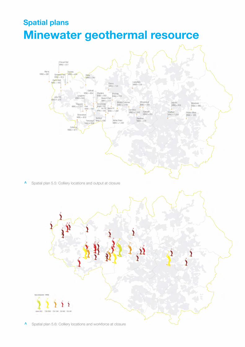
Spatial plans
Minewater geothermal resource
Spatial plan 5.5: Colliery locations and output at closure<
<
Spatial plan 5.6: Colliery locations and workforce at closure<
<

87
6.4 Standalone electricity generation
In this section we explore the potential for standalone electricity generation based on harnessing
wind and hydroelectric energy across the City Region, exploring how opportunity areas could be
identified in order to regulate development.
6.4.1 Wind power
The sub-region has the potential to support clusters of medium to large-scale wind turbines
located in areas with a commercially viable wind speed. While there would not usually be a
direct physical connection between the electricity generated and that used by developments,
under proposals by the government a link could be made between investment and associated
CO2 reductions.
Technology profile
Electricity can be generated from a suitable wind resource by modern wind turbines. These can
range in scale from small micro-wind turbines of a few kWe with a hub height of 10-15 metres
and a blade diameter of several metres, to large turbines with a rating of between 2 and 5 MWe,
a hub height of over 60 metres and a blade diameter of over 80 metres – as demonstrated by
Scout Moor in Rochdale.
Wind power is a mature technology, with the industry having a track record of nearly 30 years.
Reduction in cost and increases in turbine size and efficiency, together with market mechanisms
such as the Renewables Obligation mean that even medium-scale (1-10 MWe) projects can now
achieve a simple payback of between five and ten years based on a modest rate of return.
The amount of energy that can be extracted from a given wind resource is subject to the cube
rule, so a turbine in a location with an average wind speed of 7 metres per second will be able to
generate nearly 60% more power than a turbine in a location with an average wind speed of 6
metres per second.
Opportunities and constraints
In order to carry out a high level assessment of the opportunities and constraints in Greater
Manchester we have used as a starting point the targets stout in the North West RSS and
constraints plans drawn up for 4NW 83. A series of high-level spatial constraints have been
applied to wind speed maps of the sub-region derived from the UK Wind Speed database.
The North West RSS provides indicative targets to 2020 for onshore wind energy, which it
predicts as contributing 21.7% of the regions renewable electricity generation capacity. The RSS
works on the assumption that the majority of the potential in Greater Manchester would be
installed by 2015, and that this would account for around 15% of the regions onshore wind
energy capacity.
83 See footnote 30

AGMA Decentralised and zero carbon energy planning study 88
Table 6.2
North West RSS indicative wind energy targets 2010-2020
Sites and cumulative installed capacity (MWe)
Deployment
2010 2015 2020
Onshore farms and
clusters
5-7 (90) 6-8 (97.5) 6-8 (97.5)
Single large turbines 8 (12) 14 (21) 14 (21)
These targets are based on a target of 20% of electricity from renewables by 2020. With the
revision upwards of this target to more than 30% there will be the need to find additional wind
capacity and to utilise larger turbines to maximise electricity generation. Whilst this does not
preclude the potential for smaller installations associated with development sites or discrete
buildings, it does highlight the importance of maximising the utilisation of a given wind resource.
Scout Moor in Rochdale has an installed capacity of 65 MWe, and there are currently
applications for over 36 MWe of further capacity in the Rochdale area. This would meet the
majority of the existing RSS onshore target, but revision upwards of the 2020 targets would
mean that at least 80 MWe of capacity would be required to be brought forward.
In order to relate these overall figures to the possible spatial location of new wind energy sites a
series of constraints agreed with statutory stakeholders by Arup for 4NW can be applied in order
to begin identifying broad areas for development. These include areas that are:
‘Constrained’ by protected landscapes, nature conservation areas and related functional
areas, including a buffer zone of 500m for residential areas;
‘Variably constrained’ by heritage features, less sensitive nature conservation areas,
aviation flight path and radar areas, and deep peat sites;
‘Less constrained’ by the features and designations listed above, but which may be
subject to local designations and/or impact on greenbelt landscape character.
The 500m residential buffer is the most significant constraint, eliminating a significant proportion
of Greater Manchester. This constraint layer warrants further refining as it currently includes non-
residential locations where siting may could be possible. Additional network constraints relate to
the need for electricity connections at either 33 kV or 132 kV to the distribution network.
4NW’s application of these constraints suggests an ‘absolute’ potential for the sub-region of 118
MWe (excluding constraints and variable constraints) and 244 MWe (excluding only constraints).
This suggests that development may need to be permitted in variably constrained locations, for
example in the greenbelt, in order to deliver the higher renewable electricity targets.

89
In order to test the assumptions made by the North West RSS and by 4NW we have explored
the spatial implications of opportunity areas related to different wind speeds by producing a
series of indicative wind maps:
6.5 metres/second opportunity areas
The 4NW study assumes the exclusion of sites with a wind speed of less than 6.5
metres/second at a hub height of 80 metres. In order to ensure consistency with the RSS
targets we have used a 45 metres hub height as a starting point. The majority of the opportunity
areas identified can be seen to fall within statutory green belt.
Applications in these areas would currently be determined based on the impact on landscape
character and whether wind energy is ‘appropriate’ green belt development. There is emerging
legal precedent that while wind energy might be deemed inappropriate development the need to
tackle climate change can override this as a consideration 84.
6.0 metres/second opportunity areas
Reducing the wind speed to 6.0 metres/second at 45 metres yields a significant increase in
opportunity areas. This wind speed accords with the commercial threshold for ‘merchant wind’
type investments in 1-2 large turbines associated with industrial sites, commercial development
and Local Authority supported investment proposed by the Carbon Trust’s Partnerships for
Renewables scheme. These areas extend beyond the green belt and encompass a broad range
of land uses, including industrial sites where the impact of wind energy on landscape character
might be considered to be less acute.
84 Secretary of State’s response to an appeal made by Coronation Power Ltd, www.communities.gov.uk/documents/planning-callins/pdf/1355954.pdf

Spatial plans
Wind energy resource
Spatial plan 5.7: 6.5 metres/second at 45 metres with constraints applied<
<
Spatial plan 5.8: 6.5 metres/second at 45 metres, constraints applied and greenbelt overlaid<
<

Spatial plan 5.9: 6.0 metres/second at 45 metres with constraints applied<
<
Spatial plan 5.10: 6.0 metres/second at 45 metres, constraints applied, greenbelt and industrial sites overlaid<
<

91
Using planning to regulate development
Whilst some of the ten districts have carried out their own wind constraint mapping exercises, to
date the ten districts have not designated broad areas of opportunity for wind power in their
local plans. This has meant that planning applications have had to be dealt with on a more ad
hoc basis. Planning policies on wind may also require updating in line with the more ‘positive’
criteria-based approach in PPS1 and the likely need to bring forward more capacity than the
RSS sub-regional targets.
Our indicative wind mapping exercise has highlighted Wigan and Bolton as having the most
significant broad areas of potential, followed by Oldham and Rochdale, and, to a lesser extent,
Stockport and Bury. A refined constraints exercise would need to be guided by an agreed
methodology for assessment of impact on landscape character (including cumulative impacts) –
including limited siting within the greenbelt.
With the need for further significant site allocations having been highlighted there is the
opportunity to pre-empt further ad hoc planning applications. One approach could be to
emulate the approach taken in Germany, which has already seen the development of near to its
‘absolute’ potential in many areas 85 (see precedent study below). This would require
consultation on the designation of ‘suitable sites’ for wind power in each district, with reference
to the strategic need to bring forward sufficient capacity, to be informed by a criteria for
cumulative impact assessment.
Experience in Denmark and Northern Germany has also shown that an element of community
ownership can also increase acceptance of wind power – the opportunities for which we discuss
further in Section 8.
Precedent study Sub-regional spatial planning to regulate wind energy, Germany
National and regional programmes to support renewable energy led to a ‘dash for wind’ in the
late 1990’s and 2000’s. The result is that Germany has one of the highest installed wind energy
capacities in the world, with 23,903 MWe.
This has led to a huge amount of development pressure, as private investors have sought out
the best sites and obtain planning permission, often in the face of local opposition and a lack of
clarity over conflicting policy objectives such as nature conservation.
At a sub-regional and district level planners sought to respond by consulting on, and identifying
in local plans, ‘suitable areas’ where wind energy would be encouraged. These areas are
illustrated spatially in local plans and have helped to regulate the impact of wind energy on the
landscape, and to balance different policy objectives by applying constraints and buffer areas.
85 Bruns, E. The role of spatial planning and environmental planning in the innovation biography of wind energy in Germany, Berlin University of Technology, November 2006

AGMA Decentralised and zero carbon energy planning study 92
6.4.2 Hydroelectric power
The sub-region has the potential exploit a small hydroelectric resource. While there would not
usually be a direct physical connection between the electricity generated and that used by
developments, under proposals by the government a link could be made between the
investment and associated CO2 reductions from buildings.
Technology profile
Electricity can be generated from hydro resources where there is sufficient head of water to
create the force needed to drive an alternator. Turbines, Pelton wheels or archemedean screws
can be used to generate electricity from low head resources as small as 2-3 metres. These
would generally include weirs and locks, of which many can be found across the sub-region.
The potential can be illustrated by two distinct local examples. Barton Lock hydroelectric
scheme was installed in 1994 and has a capacity of 660 kWe 86. A single turbine was installed in
a lock forming part of Manchester Ship Canal. Torr Mill Hydro installed a 70 kWe archemedean
screw on a weir just over the border in High Peak, making use of a low head resource 87.
Opportunities and constraints
There are no definitive assessments of the extent of the sub-region’s hydroelectric resource.
ERM carried out a broad assessment as part of the regional renewables assessment in 2001
and updated in 2004 but this did not identify any new ‘viable’ sites of more than 65 kWe 88. The
North West RSS established a sub-regional target for 1 MWe of capacity by 2020, reflecting a
limited potential over and above the Barton Lock scheme and a small low head potential.
The most recent assessments include a study commissioned by Stockport MBC, which
identified five potential sites with a combined capacity of 256 KWe 89, and a study commissioned
by Groundwork Bury from the University of Lancaster, which identified two potential sites with a
combined capacity of 366 kWe 90. In each case the potential, whilst small, could be linked to
investment in discrete development sites within a close proximity.
Identification of further low head sites would require modelling of the sub-region’s catchment
areas, and a comprehensive survey of weirs and locks. This could be facilitated by the
University of Lancaster’s modelling capabilities, which have been applied to Cumbria and
Lancashire in order to identify potential.
86 CADDET (1998) Hydroelectric generating station built within a canal lock system, Technical brochure 81, www.caddet-re.org 87 Torr hydro New Mills (2009) www.torrshydro.co.uk 88 ERM, Investigating renewable energy in the North West of England: Investigating the potential and developing the targets, January 2001 89 Water Power Enterprise and H2OPE, Hydro feasibility study, Prepared for Stockport MBC, November 2008 90 Lancashire University Engineering Department (2006) Presentation to Groundwork (Bury) on renewable energy in the Bury area

93
6.5 Biomass supply chain
In this section we explore the implications for development of a biomass supply chain to supply
CHP and heating plant, drawing on a range of different wood fuel resources, including those
available within the City Region.
Early indications are that, in addition to wind power and solar photovoltaics, biomass heat and
power generation is likely to be one of the most cost effective and widely applied means of
achieving Code for Sustainable Homes levels 5 and 6. The ability to source biomass fuel on a
firm contracted basis and to the appropriate specification will therefore be vital to support any
growth in demand stimulated by planning and regulation.
6.5.1 Planning for growth in demand
In order to understand how the sub-region might plan for this growth sub-region it is important
to understand the nature of the supply chain. Biomass fuel comes in broadly two mains forms:
Pellets are manufactured from wood wastes such as from sawmills and are more
suitable for smaller installations because they have a high energy density and therefore
require less transport and storage;
Wood chips are a raw wood product, and can be produced from a range of sources
including commercial wood waste, forestry residue, municipal tree waste and energy
crops. Chips often have a higher and variable moisture content.
Larger biomass CHP and boiler plant tend to make use of wood chips because they allow for
more flexible sourcing and because they are, at present, on balance cheaper.
An increasing number of local authorities are turning to biomass as a relatively cheap and
efficient way of switching over the heating supply for public buildings and housing schemes with
district or communal heating. Barnsley Council is leading the way with it’s ‘biomass fuel heating
policy’, which has been complemented by investment in their supply chain based on the districts
arborological waste and managed forestry resources 91 (see case study below).
6.5.2 The North West supply chain
The supply chain for biomass fuel in the North West region, and within the city-region is at an
early stage of development. There are broadly three potential sources that we have considered
at a strategic level:
Existing producers
We have mapped the existing biomass chip and pellet producers in and around the city-region
based up to date information from Envirolink North West's biomass directory 92. This suggests
91 Bradford, D, Wood – today’s heating fuel, presentation by Principal Building Services Engineer, Barnsley Metropolitan Borough Council, November 2006 92 Envirolink North West, Biomass fuel supply in England’s North West, April 2007

AGMA Decentralised and zero carbon energy planning study 94
that although there are a number of large producers in the sub-region, such as Hadfields in
Tameside, much of their output is currently contracted to biomass power stations elsewhere in
the region or in southern Scotland. There are also concerns about the suitability of biomass
produced from commercial waste streams, which may include contaminants, potentially making
it unsuitable for smaller boilers or CHP plant.
Local authority arboricultural waste
Survey work by Red Rose Forest has produced estimates for wood chips that might be available
from at least eight of the districts from street tree and park tree waste. This suggests that
around 4,267 Oven Dried (OD) tonnes/annum of wood chip might be available in the sub-region
– although this figure may fluctuate year on year 93. There are indications that much of this
wood chip is currently sold on by Councils and contractors and very little is landfilled 94.
Managed forestry
In recent years the establishment of Community Forest programmes across the sub-region,
pioneered by Red Rose Forest and Pennine Edge Forest, has led to the promotion of managed
forestry that could generate economic value from by-products such as wood chip. The
Newlands Programme has aimed to establish woodland-based regeneration projects.
Estimates of the biomass fuel potential of this programme are not readily available, however,
DEFRA’s agricultural and horticultural survey (2007) suggests that there are 580 hectares of
woodland in the sub-region which if managed could yield, based on Forestry Commission
estimates, approximately 1,160 OD tonnes/annum of wood chip.
Energy crops
Fast growing woody crops such as Short Rotation Coppice willow can be grown on lower grade
agricultural land. DEFRA’s agricultural and horticultural survey (2007) suggests that there are 479
hectares of setaside land that could be used for energy crops. This could create an absolute
potential yield approximately 4,790 OD tonnes/annum. It is likely that a wider approach,
encompassing rural areas across the region would be needed to contract supply.
Overall these estimates suggests that with co-ordination of the sub-region’s supply chain there
could be access to 10,217 tonnes/annum, supplemented by access to a wider regional supply
chain from which a proportion of an estimated 325,000 tonnes/annum could be contracted 95.
93 Red Rose Forest and Mersey Forest, Of chips and logs…making the most of arboricultural arisings in the Mersey Belt, July 2006 94 Discussions with Phil Benn, Manchester Tree Station, contractor to Red Rose Forest 95 North West Regional Forestry Framework (2009) Biomass woodfuel strategy

Spatial plan 6.11
Biomass producers
Spatial plan 6.11: Large-scale producers of biomass fuel in the North West<
<
AGMA Decentralised and zero carbon energy planning study 96
6.5.3 The logistics of increased demand
Larger demands for fuel could at present only be met on a firm basis by importing fuel from
other parts of the region such as Cumbria, other regions, such as Yorkshire and Scotland or
from other EU countries via ports on Liverpool or Humberside. For example, Renewable Fuels
(part of the Swedish Lantmånnen agricultural co-operative) based in Yorkshire currently supply
large tonnages of wood chip to power stations such as Drax.
The import of biomass fuel raises two major concerns that require addressing. The first is fuel
price. Biomass is generally transported by lorry, and its cultivation (in the case of energy crops),
harvesting (energy crops and forestry residue) and production is also reliant on fossil fuels. This
means that the price is strongly influenced by oil prices, at a time when energy customers are
looking to fuels such as biomass in order to decouple renewable energy and fossil energy prices.
As far as possible fuel supply chains should therefore be developed as near as possible to the
sub-region, and based on by-products, suggesting that the area of search should firstly focus on
other areas of Lancashire and Cheshire, as well as by-products available from North Wales
industries such as sawmills. Barnsley MBC’s development of a district supply chain to serve its
biomass heating programme provides precedent for this approach 96, and this approach could
be taken further in the City Region with the potential to invest in wood pellet production plant(s).
The second issue are CO2 emissions relating to harvesting, processing and transport of the fuel.
There is conflicting evidence as to the emissions arising from producing and transporting
biomass. A recent report by the Environment Agency provides the most definitive data,
suggesting a reduction in CO2 savings of between -5% (wood chip) and -18% (wood pellets) for
European imports, but the data is not clear for transport within the UK 97.
If biomass fuel were to be imported from discrete other sub-regions, or other countries, there
could be the potential to utilise rail infrastructure to transport the fuel in a way that minimises
lorry movements. Reverse logistics could be used in certain instances. For example, municipal
waste is currently transported to landfill sites on Humberside in iso-freight containers that return
empty. Humberside is a major point of arrival for biomass imports from Scandinavia and Russia
and has been a focus for investment by Yorkshire Forward.
96 See footnote 95 97 Environment Agency, Minimising greenhouse gases from biomass energy generation, April 2009

97
Precedent study Barnsley biomass heating and fuel supply
Barnsley Council has set an ambitious target to reduce its emissions 60% by 2015 primarily by
switching to biomass heating. This has been adopted at member level as the ‘biomass fuel
heating policy’. Working with biomass heating specialists Econergy the council have initiated a
switch over programme. To date this included the new civic centre, the central library, all
schools, council blocks of flats, and a new digital media centre.
In support of its corporate biomass fuel heating policy Barnsley Council has sought to develop
a stable and cost effective supply of wood fuel. The council has carried out a survey of the
available biomass resources in the district, and has established wood fuel handling centres to
supply its boiler switchover programme. The centres will handle and process a range of wood
including tree surgery waste and forestry residue.

AGMA Decentralised and zero carbon energy planning study 98
6.6 Building integrated heat and power
In this section we explore the potential for building integrated ‘micro-generation’
technologies, including solar thermal, solar photovoltaics, biofuelled boilers and heat
pumps, to provide on-site heat and power.
Micro-generation technologies have a smaller but still significant role to play in delivering low and
zero carbon energy supplies. This is because the majority of new homes projected for the sub-
region are likely to be developed at a lower density, requiring solutions for small clusters of
homes, or on individual homes.
Achieving greater deployment of micro-generation creates a different challenge from networks
and standalone technologies. They will require installation on many thousands of individual
properties. At this scale the unit costs are at their highest and so achieving economies of scale
and greater repetition by contractors will be essential.
Micro-generation technologies are also notable in planning terms because, for the most part,
they are now permitted development. Rules were relaxed following the Government’s 2006
micro-generation strategy, but the main barrier to their widespread deployment remains their
higher upfront capital cost compared to a number of the networked and standalone
technologies reviewed by this study.
6.6.1 Solar thermal
Solar thermal collectors are a mature technology that can be installed on buildings in order to
supplement their hot water supply. Carbon emissions savings are achieved because it displaces
hot water provided by gas or electric heating systems. The technology has a track record of
over 30 years in the UK, and was one of the most commonly installed technologies supported
under the Government’s Low Carbon Building Programme.
Solar thermal technology takes two main forms - flat plate panels or evacuated tubes installed
on the roof of a building. Water is circulated through the panels and tubes, and is warmed by
the sun and then provides hot water for building occupiers. Installed on a typical home it can
typically provide between 50% and 60% of the annual hot water requirements, equating to a
15% gross CO2 reduction for a home built to 2006 Building Regulations, enabling homes to
achieve Code levels 3 and 4.
6.6.2 Solar photovoltaics
Solar photovoltaics are a mature technology that can be installed on buildings in order to
generate electricity from sunlight. Photovoltaics are a form of semi-conductor that generates
Direct Current (DC) power from sunlight. The DC electricity generated is then rectified to AC
current by an inverter. The most common form are polycrystalline cells arranged to form
standardised modules or panels, which can be fixed to, or integrated into roofs and facades.

99
The power output from photovoltaics closely matches the peak demand for comfort cooling in
summer, but they can also assist in meeting daytime power demands from spring through to
autumn. This makes them particularly suitable for meeting the power needs of commercial office
blocks and public buildings. This power output will also help to reduce load on the local
distribution grid, and it can be exported in order to obtain Renewables Obligation Certificates
(ROC’s) and in 2010 a higher value ‘Feed-in Tariff’.
Photovoltaics are receiving attention as a technology because they can assist new homes to
reach Code for Sustainable Homes level 6. This is because, despite their high capital costs, they
are one of the few low carbon technologies that can supply electricity in sufficient quantities to
meet the needs of detached or semi-detached homes, which in many cases may not be suitable
for energy networks. With the introduction of Feed-in Tariffs in April 2010 it will become viable to
offset the high capital costs against the revenue from electricity sales.
6.6.3 Biomass boilers
Biomass boilers are a mature technology and they are available in a range of sizes, from those
that can supply district heating networks and large buildings to those designed for a single
home. Simpler biomass stoves supplying hot water via a back boiler can also be specified for
homes with a very low heating demand.
As we discussed in section 6.5 biomass fuel comes in two mains forms – wood chips and
pellets. Pellets are manufactured from wood waste and are more suitable for smaller
installations because they have a high energy density and require less storage. A larger boiler
plant would tend to make use of wood chips because they allow for more flexible sourcing and
because they are cheaper.
Biomass boilers, like biomass CHP, are receiving significant attention because they can provide
developments with zero carbon heating, enabling them to achieve Code levels 4 or 5 – as
demonstrated by Rocks Green in Shropshire 98 (see precedent below). All demonstration homes
meeting Code level 6 have had to incorporate biomass heating – albeit at a much higher unit
cost than for schemes with district heating networks.
In London higher on-site renewable targets have led biomass boilers to be the favoured
technology. Whilst modern plant are very clean the cumulative impact of unconstrained biomass
use does, however, create a potential risk to air quality – directly from boilers and indirectly via
associated fuel deliveries. This issue was discussed in Section 6.2.4.
98 Sustainable Housing Action Programme (SHAP) (2008) Case studies of low carbon housing, www.shap.uk.com

AGMA Decentralised and zero carbon energy planning study 100
Precedent case study Rocks Green housing scheme, Shropshire
Rocks Green is a development of 91 new semi-detached homes by South Shropshire Housing
Association in Ludlow, South Shropshire. All of the homes are supplied with their space heating
and hot water from communal wood chip boilers, with heat distributed to each property via
1,200 metres of pre-insulated district heating mains.
The boiler house contains two 150 kW Austrian KWB boilers together with a 200 kW oil-fired
standby boiler and a thermal storage tank. The storage tank is required in order to match the
supply and demand for heating. The development has been estimated to require 200 tonnes of
wood chips per year. The fuel is to be supplied under a contract with Midlands Wood Fuel,
which was established by Marches Energy Agency. The contract is based on the heat output
delivered by the fuel.
6.6.4 Heat pumps
Heat pumps are a mature technology that can provide heating and cooling using the same
technology as a refrigerator or air conditioning system, with electricity or heat being used to raise
or lower the temperature of air or water.
Typically a heat pump can deliver three units of heat for every unit of electricity or heat, but this
will vary depending on the ‘Co-efficient of Performance’, which in turn is dependant on the
temperature of the heat source. Sources in increasing order of efficiency could include:
Air (ambient or from an industrial process),
Surface water (canal, river or lake),
Geothermal (soil or groundwater),
Wastewater (sewage or industrial effluent).
The heat can either be extracted using a ‘closed loop’ network of pipes through which
refrigerant is circulated, or a ‘direct loop’ with water pumped from a watercourse or borehole
and then through a heat exchanger.
Heat pumps can be used to provide heating and cooling to individual buildings and homes.
However, in built up areas constraints on land may limit the potential for a closed loop system.
In these locations a direct loop system based on a resource such as an aquifer would represent
a better heat source. The latter has been show to be an economical solution for large offices
and apartment blocks.
It is important to note that heat pumps require an input of energy, and their carbon reduction
potential is limited by CO2 emissions from this input, which is usually grid electricity. BRE trials
have shown that a modern house with gas-fired heating can make a 15% reduction in CO2

101
emissions by using a heat pump 99. This performance will improve over time as carbon
emissions from the electricity supply reduce.
99 Energy Saving Trust, Heat pumps in the UK: A monitoring report, GIR 72, November 2005

AGMA Decentralised and zero carbon energy planning study 102
6.7 What are the opportunities and constraints for the City Region?
This study has explored the ‘top down’ spatial planning implications for a range of low and zero
carbon technologies. Each creates distinct opportunities for the sub-region, but also have
specific constraints which will need to be overcome in order to increases deployment in-line with
the UK renewable energy strategy and the need for low and zero carbon infrastructure for new
development.
In order to make progress the targets set out in the North West RSS and refined further by 4NW
need to be given a greater spatial context – bringing them down to sub-regional, district and
site-specific level in order to understand the implications. The range of technologies will also
need to expand in order to cover heat, and to exploit the full range of low and zero carbon
technologies that will be needed to meet overarching carbon reduction targets.
An outline framework of ‘top down’ deployment targets for the City Region is set out in table 6.3.
The implications for deployment of these technologies to achieve carbon reductions are then
explored by the ‘bottom up’ case study evidence base.
6.7.1 Networked technologies
A series of networked technologies are likely to create the most significant medium term scope
for CO2 reduction. Each creates strategic opportunities whose contribution would be over and
above those identified by targets in the North West RSS and the recent study for 4NW. In
particular the role of natural gas fired CHP as an interim low carbon technology to deliver CO2
reductions is not currently accounted for, and could play a significant role – particularly if waste
heat was to be utilised from the proposed Carrington CCGT Power Station.
This suggests that clear deployment targets for low carbon technologies will be required for the
sub-region, alongside existing renewable energy targets. The opportunities for deployment of
these technologies are fundamentally linked to the built environment because of the need to
supply district heating. Targets should only therefore be set in conjunction with a spatial plan
that gives them context.
6.7.2 Standalone power generation
Challenging regional targets for the deployment of wind power at a sub-regional scale raise
important issues as to how planning could be used to bring forward new capacity. Large-scale
onshore wind power will be needed to supply electricity to the major centres where demand is
located and in order to offset unregulated emissions from lower density housing developments
which are likely to make up the majority of the projected housing numbers.
In order to avoid a continued ‘dash for wind’ on viable sites by prospective developers the
districts should look to identify and allocate suitable sites so that they can exercise more control
over the process and, more importantly, its cumulative impact on landscape character. This is
likely to include the need for some development in the greenbelt. Sites are also likely to be
required for wind turbines financed in part from developer contributions.

103
6.7.3 Fuel supply chains
Fuel supply chains will be required for heat and power generation, requiring the development of
resources and logistics in order to provide security of supply. At present the position is entirely
market-led. However, a large increase in demand for biofuels could have significant implications,
and unintended consequences, if not planned for at a strategic level. This should include
consideration of options such as transport by rail and site allocation for fuel storage depots.
Biomass wood fuel has been identified as important by a range of strategies, but the
development of a wood fuel supply chain that decouples biomass energy prices from oil prices
(for transport of the fuel) is likely to be constrained. The City Region is therefore be likely to be
reliant for biomass on the region’s rural areas, or even further afield, in order to respond to
market-led growth in demand.
6.7.4 Micro-generation technologies
Micro-generation will have an increasingly important role to play in relation to lower density and
smaller clusters of housing, particularly if the cost of technologies such as solar photovoltaics
can be brought down over the next decade. Given the granting of Permitted Development rights
for most technologies, market development programmes to achieve economies of scale are
likely to be more important than planning at this scale. Investment vehicles that are geared up to
finance technologies such as solar photovoltaic’s using FIT revenue – thereby reducing the
capital costs for developers - may also be needed.

AGMA Decentralised and zero carbon energy planning study 104
Table 6.3
City Region strategic energy infrastructure
Technology
Description Scale of potential
(MW electricity or thermal)
Technical requirements
Small to medium-scale gas or
biomass power generation (1-50
MWe) supplying district heating.
Regional Centre (at least 50
MWe), 8 sub-regional centres
(5-10 MWe), 34 local centres
(1-2 MWe), major regeneration
areas (at least ten 1-2 MWe)
District heating networks supplying mixed
use areas with a high heat density;
Allocation of sites for energy centres and/or
integration into development;
Small-scale biogas power generation
or energy from waste (1-10 MWe)
supplying district heating.
At least three waste PFI sites
(3-6 MWth), two sewage gas
sites (7 MWth) and one landfill
gas site (7 MWth)
Alignment of investment strategies to
support heat offtake to supply development;
Agreements governing operational
arrangements and pricing for heat off take.
Combined Heat and
Power (CHP)
Power stations (up to 800 MWe)
supplying industrial steam and district
heating.
Carrington Power Station
(300 MWth in two phases)
Heat pipeline routed to supply Growth Point
sites and Regional Centre;
Operational agreement for heat off take with
Carrington Power;
Geothermal heating Deep boreholes (~25 MWth each)
supplying district heating
Initial 25 MWth site, South
Manchester and Trafford
(unconfirmed potential)
Further seismic studies to validate potential
across broad area;
District heating network(s) to utilise thermal
resource.

Minewater from old workings (5.3
MWth per site) supplying district
heating
33 sites (176 MWth) in
Manchester, Salford, Wigan,
Bolton and Tameside.
Technical studies of selected workings to
validate potential;
District heating networks to utilised thermal
resource;
Wind power Small farms or clusters of turbines
(3-10 MWe) and single turbine sites
(1-2 MWe) utilising wind resource
greater than 6.0-6.5 m/s
53 – 179 MWe (variable by
constraints). Farms in Oldham,
Rochdale, Bolton, Wigan and
Tameside. Clusters in Bury,
Salford and Stockport. Single
turbine sites in all districts.
Refinement and application of constraints in
order to identify opportunity sites;
Agreed methodology for assessing
landscape impact and cumulative impacts;
Hydroelectric
Small head hydro sites (60-250kWe)
utilising weirs and mill races with a
head of more than 2 metres
622 kWe new capacity in Bury
and Stockport, with additional
unconfirmed potential in Bolton,
Rochdale and Oldham and
Ashton.
Detailed modelling and design of existing
potential sites;
Scoping of watercourses for new sites in
other districts.