6 engine design using state-of-the-art tools engineengine · pdf fileengine design using...
TRANSCRIPT
MAN forschen planen bauen 2002 6.1
Dies ist ein MUSTERTEXT Mustertext
MAN B&W Meeting of Licensees Augsburg 2002 6.1
Engine design using state-of-the-art tools
6
Engine
design
Engine
design
Engine
design
Methods for an efficient shortening of
the development times . . . . . . . . . . . . . . . . . . . . . . 6.3
Steps involved in producing a
preliminary design . . . . . . . . . . . . . . . . . . . . . . . . . . 6.3
Use of the 3-D data for design,
calculation and simulation . . . . . . . . . . . . . . . . . . . 6.5
Using the models in production . . . . . . . . . . . . . . 6.6
What concrete benefits did
state-of-the-art tools bring to the
L21/31cylinder crankcase project? . . . . . . . . . . . 6.10
Dr. Thomas Schuszter
Helmut Christl

Engine
design
Engine
design
Engine
design
6.2 MAN B&W Meeting of Licensees Augsburg 2002
Engine design using state-of-the-art tools

MAN B&W Meeting of Licensees Augsburg 2002 6.3
Design Pro/E
Calculation ANSYSDesignspace
Pattern building Pro/E Casting
Foundry Procast
Machining Pro/E UDFNC-Programming EXAPT
VericutNC-Simulation
Pattern production
NC machining elements
Simulation of casting process
Documentation
Rapid prototyping
StrenghtVibration
Draft Details
Pattern planning
2 Simultaneous Engineering process of a casting product.
ENGINE DESIGN USINGSTATE-OF-THE-ART TOOLSILLUSTRATED BY THE L21/31CYLINDER CRANKCASE
Methods for an efficient shortening of the development timesThe market anticipates from enginedevelopers products which ensurehigh reliability over many years of economical operation despite a low purchase price. In addition, more and more ecological and environment-relevant aspects cometo the fore. Continuously shorterdevelopment times are available tothe offer in order to comply withthese demands.
When developing new engines, wefulfil these requirements by usingmodern data processing systemsboth in the R&D and in the produc-tion range. In connection with simultaneous engineering methods,which are characterised by overlap-ping work sequences and a closecooperation between the variousexpert departments, a continuousprocess from the idea to the com-plete component can be realised.
Key advantages this method offersare:❒ improvement of process and
product quality❒ shortening of product develop-
ment times, and❒ improved staff motivation.
Here at MAN B&W data based on the3-D CAD program PRO/ENGINEERare used as the basis for the sub-sequent processes (Fig. 1).
1 Universal use of the 3-D data.
It is the intention of this paper to illustrate these processes and theresultant benefits by taking the development of the L21/31 cylindercrankcase as an example (Fig. 2).
Steps involved in producing apreliminary design
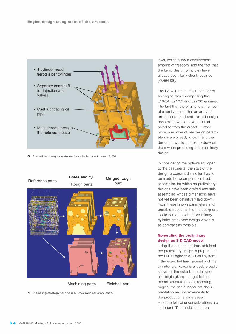
Design and concept definition in the design departmentWhen designing a cylinder crankcase(Fig. 3) a distinction has to be madebetween the many possibilities opento the design engineer at the detailed
6.4 MAN B&W Meeting of Licensees Augsburg 2002
Engine design using state-of-the-art tools
level, which allow a considerableamount of freedom, and the fact thatthe basic design principles havealready been fairly clearly outlined[KOEH-98].
The L21/31 is the latest member ofan engine family comprising theL16/24, L21/31 and L27/38 engines.The fact that the engine is a memberof a family meant that an array ofpre-defined, tried-and-trusted designconstraints would have to be ad-hered to from the outset. Further-more, a number of key design param-eters were already known, and thedesigners would be able to draw onthem when producing the preliminarydesign.
In considering the options still opento the designer at the start of thedesign process a distinction has tobe made between peripheral sub-assemblies for which no preliminarydesigns have been drafted and sub-assemblies whose dimensions havenot yet been definitively laid down.From these known parameters andpossible freedoms it is the designer'sjob to come up with a preliminarycylinder crankcase design which is as compact as possible.
Generating the preliminary design as 3-D CAD modelUsing the parameters thus obtainedthe preliminary design is prepared inthe PRO/Engineer 3-D CAD system.If the expected final geometry of thecylinder crankcase is already broadlyknown at the outset, the designercan begin giving thought to themodel structure before modellingbegins, making subsequent docu-mentation and improvements to the production engine easier.Here the following considerations areimportant. The models must be
3 Predefined design-features for cylinder crankcase L21/31.
4 Modelling strategy for the 3-D CAD cylinder crankcase.
MAN B&W Meeting of Licensees Augsburg 2002 6.5MAN B&W Meeting of Licensees Augsburg 2002 6.5
necessary stiffenings in the windowarea.
This usually involves deriving a shellstructure of the 3-D engine design in order to keep the model size at anefficient level for the simulation. As asolid model the CAD model is alreadytoo complex at the design stage tobe able to retroactively produce anautomatic shell structure; features arehowever already contained in various
❒ well defined❒ easily changeable and stable❒ usable for FEM calculations, i.e.
simplifications must be possible,❒ suitable for subsequent pro-
cesses, such as producing mould patterns.
Model performance should not belost at high degrees of detail and thegeneration and maintenance of othercylinder numbers should be quickand simple.
In our cylinder crankcase examplethe following characteristics haveproved to be advantageous:❒ Modelling was performed in
cylinder sections with a patterned structure. This means that the cylinder numbers of production documentation can be generated very quickly from a prototype frame. Designers mainly work with manageable patterns with few design elements.
❒ Cavities were modelled as cores. This method makes rounding easier since the designer can see the areas requiring rounding from the outside. The models can easily be used for actual coring.
❒ For processing a number of sur-face models were produced and, if possible, built up as cylinder parts. For irregular patterns an additional machining part was produced over the entire length of the crankcase (Fig. 4).
Use of the 3-D data for design,calculation and simulation
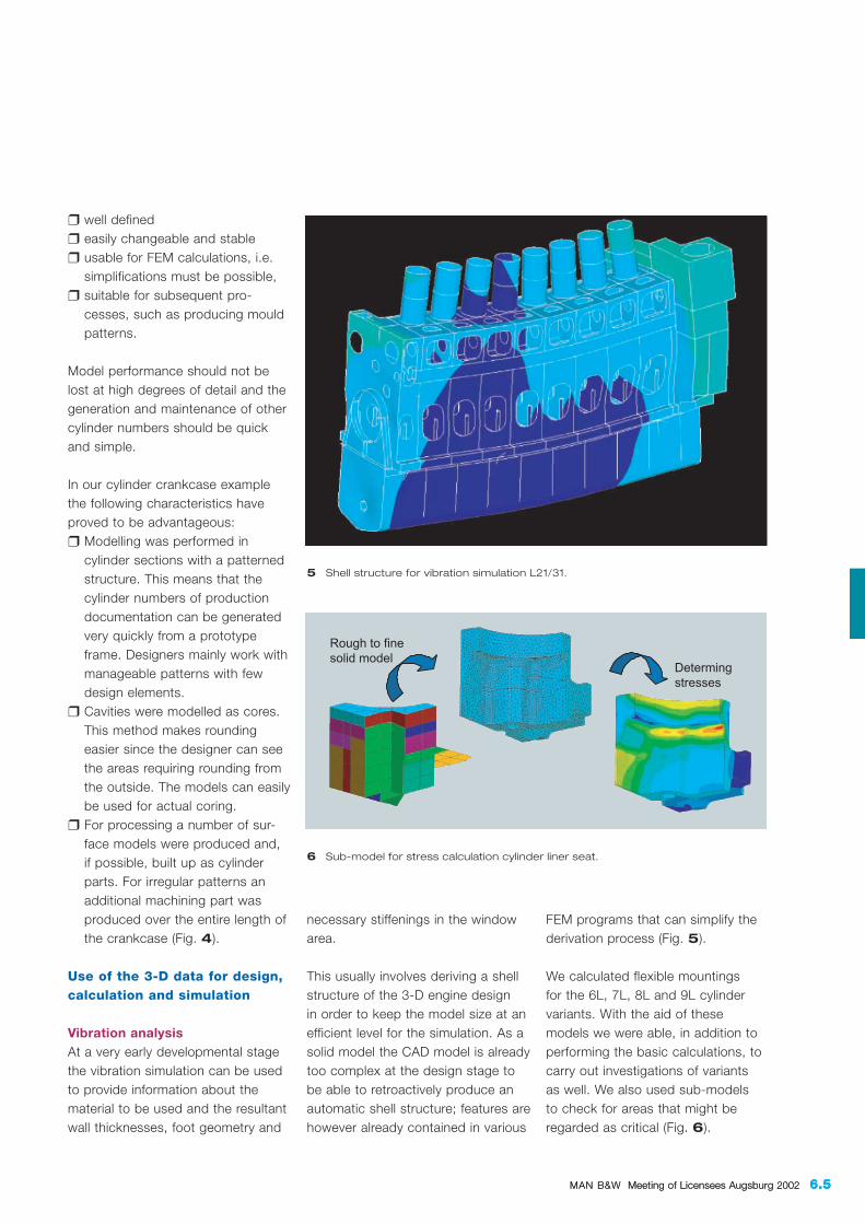
Vibration analysisAt a very early developmental stagethe vibration simulation can be usedto provide information about thematerial to be used and the resultantwall thicknesses, foot geometry and
FEM programs that can simplify thederivation process (Fig. 5).
We calculated flexible mountings for the 6L, 7L, 8L and 9L cylindervariants. With the aid of thesemodels we were able, in addition toperforming the basic calculations, tocarry out investigations of variants as well. We also used sub-models to check for areas that might beregarded as critical (Fig. 6).
5 Shell structure for vibration simulation L21/31.
6 Sub-model for stress calculation cylinder liner seat.

6.6 MAN B&W Meeting of Licensees Augsburg 2002
Engine design using state-of-the-art tools
The vibration calculation produced a required outer wall thickness of 16 mm. Since additional rigidity isrequired for resilient mountings, itwas decided to opt for a stiffer oilsump for this particular application.
The foot geometry defined in thepreliminary design was confirmed asbeing sufficiently stiff. It was decided
7 Casting positions.
8 Pro/E model core structure.
wherever possible since they do not play a major role in static calcu-lations. Having first consulted thedesigner, the calculator left curvesrecognised as critical in the model in order to avoid errors occasionedby singularities.
The model was produced paramet-rically to the original model, i.e. alterations in the design were incor-porated into the calculation model byregenerating the calculation model. A section was taken from the cylindercrankcase from centre-window tocentre-window and examined withthe three critical load scenarios:❒ cylinder crankcase in pre-loaded
state❒ cylinder crankcase subjected to
mass force❒ cylinder crankcase subjected to
firing force.
The results of the simulation wereused to implement improvements in way of the collar bush. Criticalareas caused by core supports werestress-optimised. In addition, the calculations indicated that EN-GJS-400 was the only material that shouldbe used for the frame of the L21/31and not grey cast iron.
Using the models in production
Cooperation between the design department and thefoundryAt the same time as the simulationswere being carried out the first foundry decisions were taken.
The production costs of the blanksare considerably influenced by thecasting position of the parts as itdetermines the number of the coreswhich is required for mould manufac-ture. Since the start-up of the new
that stiffening of the rear side of thewidow was not necessary.
Static calculation on a crank-case sectionFor the static calculation of the component a simplified two-cylindermodel was prepared in order to saveon computer resources. Unnecessaryexternal roundings were suppressed
Old position:a lot of cores
New position:fewer cores

MAN B&W Meeting of Licensees Augsburg 2002 6.7
9 From 3-D model to sand core.
11 Coring
up the
mould.
10 Core making.
type series, all cylinder crankcasesare cast lying on their sides (Fig. 7),which permits reducing the cores for the 8L 21/31 cylinder crankcaseto only 13.
Pattern- and mould-makingThe main work in the foundry on thePro/E model involves designing the
pattern. Owing to the associativity of the Pro/E models this work is performed simultaneously with theother work on the raw casting model,the geometry of the raw castingalways serving as the reference. Allthe required cores with their coreprints and the geometry of the modelare derived from it.
A 3-D model of the core structurefrom the 1L21/31 cylinder crankcaseis sufficient for virtual check of themould-making method (Fig. 8).
This is then followed by production of the physical foundry pattern. Thisinvolves a combination of manual andmachine production in order to keepcosts to a minimum. All free-formsurfaces are milled directly on CNCmachines using the relevant 3-D geometry data. Time is saved bychecking the dimensions directlyagainst the Pro/E model with the aid of the computer. This procedure produces significantly more accuratepatterns, as well as considerablyreducing pattern production times(Fig. 9).
For filling and curing, all cores aremade on high-performance coreshooters (Fig. 10). Not only does this significantly reduce the numberof individual cores, the foundry isalso able to complete the orders inan extremely short time (Fig. 11).
13 cores areputting in the mould
Closing of the mouldafter only 4 hours
6.8 MAN B&W Meeting of Licensees Augsburg 2002
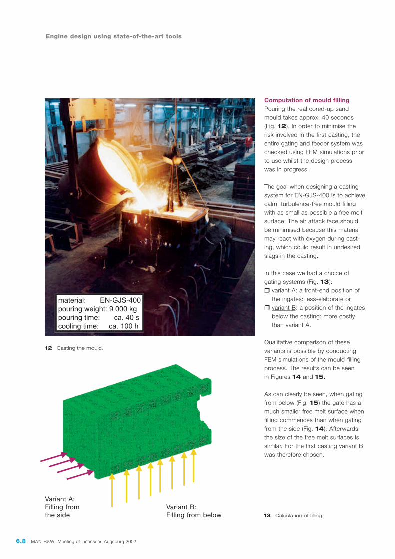
Computation of mould fillingPouring the real cored-up sandmould takes approx. 40 seconds(Fig. 12). In order to minimise therisk involved in the first casting, theentire gating and feeder system waschecked using FEM simulations priorto use whilst the design process was in progress.
The goal when designing a castingsystem for EN-GJS-400 is to achievecalm, turbulence-free mould fillingwith as small as possible a free meltsurface. The air attack face shouldbe minimised because this materialmay react with oxygen during cast-ing, which could result in undesiredslags in the casting.
In this case we had a choice ofgating systems (Fig. 13):❒ variant A: a front-end position of
the ingates: less-elaborate or❒ variant B: a position of the ingates
below the casting: more costly than variant A.
Qualitative comparison of these variants is possible by conductingFEM simulations of the mould-fillingprocess. The results can be seenin Figures 14 and 15.
As can clearly be seen, when gatingfrom below (Fig. 15) the gate has amuch smaller free melt surface whenfilling commences than when gatingfrom the side (Fig. 14). Afterwardsthe size of the free melt surfaces issimilar. For the first casting variant Bwas therefore chosen.
Engine design using state-of-the-art tools
13 Calculation of filling.
12 Casting the mould.
Variant A:Filling fromthe side
Variant B:Filling from below

MAN B&W Meeting of Licensees Augsburg 2002 6.9
Solidification simulationThe solidification simulation is usedto design the cooling and feedingsystem for the casting. This involvescalculating the temperature distribu-tion and the solidification process ofthe component over time (Fig. 16).An unfavourable solidification pro-cess with resulting micro porosities is counteracted by changes in thecooling and feeding system.
The simulation calculations carriedout were an extremely valuable helpin order to obtain a low-cost andfault free first cast of the cylindercrankcase.
16 FEM simulation of
cooling and
solidification process.
14 Variant A: mould filling from the side.
15 Variant B: mould filling from below.

6.10 MAN B&W Meeting of Licensees Augsburg 2002
In the future it may be possible tosimulate these processes as an as-sembly film (Fig. 18). This will raisetheir information content significantly.The cost of producing these films will be about the same as the cost ofproducing drawings.
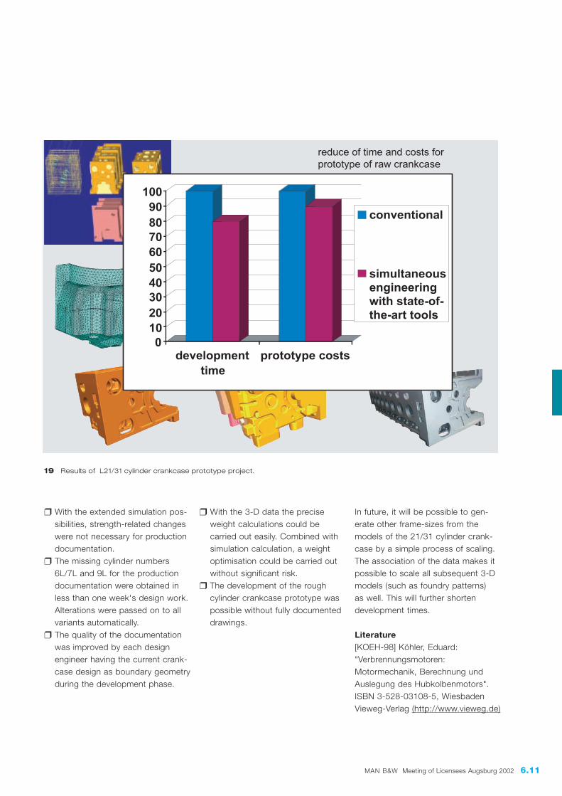
What concrete benefits did state-of-the-art tools bring to the L21/31 cylinder crankcaseproject?The main advantage in the case of the L21/31 project proved to be a significant reduction in developmenttime to generation of the cylindercrankcase prototype and hence toavailability of the engine prototypes(Fig. 19).
Additional, secondary benefits com-pared with conventional methodswere:
Engine design using state-of-the-art tools
Machining3-D models are being used for machining for❒ jig design❒ programming 3-D co-ordinate
measuring machines❒ NC programming of machining
centres❒ checking of collisions of the
machining process.
By the simulation of tool paths inmachining centres a control and opti-misation of the program processes is possible without the need to carryout costly running-in trials of the program on the machine tool. Oncethe machine kinematics, the tool data,the milling and boring program andthe component's 3-D data have beenloaded the NC program is run as adynamically calculated film. Machiningelements generated at the componentare visualised, as are any collisionsbetween the machine and the com-ponent (Fig. 17).
Simulation of assembly proceduresAt present assembly procedures andmaintenance work are depicted usingdrawings derived from the 3-D data.
18 Simulation of fitting and removing of a conrod bearing.
17 Simulation of tool paths in machining centres.
MAN B&W Meeting of Licensees Augsburg 2002 6.11
❒ With the extended simulation pos-sibilities, strength-related changes were not necessary for production documentation.
❒ The missing cylinder numbers 6L/7L and 9L for the production documentation were obtained in less than one week's design work. Alterations were passed on to all variants automatically.
❒ The quality of the documentation was improved by each design engineer having the current crank-case design as boundary geometry during the development phase.
❒ With the 3-D data the precise weight calculations could be carried out easily. Combined with simulation calculation, a weight optimisation could be carried out without significant risk.
❒ The development of the roughcylinder crankcase prototype waspossible without fully documenteddrawings.
19 Results of L21/31 cylinder crankcase prototype project.
In future, it will be possible to gen-erate other frame-sizes from themodels of the 21/31 cylinder crank-case by a simple process of scaling.The association of the data makes itpossible to scale all subsequent 3-Dmodels (such as foundry patterns) as well. This will further shorten development times.
Literature[KOEH-98] Köhler, Eduard:"Verbrennungsmotoren: Motormechanik, Berechnung undAuslegung des Hubkolbenmotors".ISBN 3-528-03108-5, WiesbadenVieweg-Verlag (http://www.vieweg.de)

6.12 MAN B&W Meeting of Licensees Augsburg 2002
Engine design using state-of-the-art tools