6 design and operating notes - sew-eurodrive · 2018. 10. 1. · 6 design and operating notes...
TRANSCRIPT

6 Design and operating notesLubricants
6
Catalog – DRS/DRN.. Gearmotors 109
2193
3480
/EN
-US
– 0
4/20
18
6 Design and operating notes
6.1 Lubricants
6.1.1 General information Error! B ookmark not d efined .Error! Boo kmark not defin ed .
INFORMATION
Unless a special arrangement is made, SEW-EURODRIVE supplies the drives with a lubricant fill adapted for the specific gear unit and mounting position. The mounting position must be specified with the order (→ 69).
When the mounting position is changed, the lubricant fill quantity must be adjusted (see “Oil fill quantities” (→ 113)). Therefore, to maintain your warranty rights, please consult with SEW-EURODRIVE when changing a mounting position.
6.1.2 Bearing greases Error! B ookmark not d efined .Error! Boo kmark not defin ed .
The gear unit rolling bearings are factory-filled with the greases listed below. SEW-EURODRIVE recommends re-greasing the rolling bearings with a grease filling at the same time as changing the oil.
Type Ambient temperature
Manufacturer Type
Gear unit bearings
mineral -20 °C to +60 °C Shell Gadus S2 V220 2
synthetic -40 °C to +80 °C Shell Gadus S5 V100 2
-20 °C to +40 °C Klüber Klübersynth
UH1 14-151
-20 °C to +40 °C Klüber Klüber M 72-82
Motor bearings
mineral -20 °C to +80 °C ExxonMobil Polyrex EM
Synthetic -40 °C to +60 °C Kyodo Yushi Multemp SRL
INFORMATION
The following grease quantities are required:
• For fast-running bearings (gear unit input side): Fill the cavities between the rolling elements one-third full with grease.
• For slow-running bearings (gear unit output end): Fill the cavities between the rolling elements two-thirds full with grease.
OilOil
6 Design and operating notes Lubricants
Catalog – DRS/DRN.. Gearmotors 110
2193
3480
/EN
-US
– 0
4/20
18
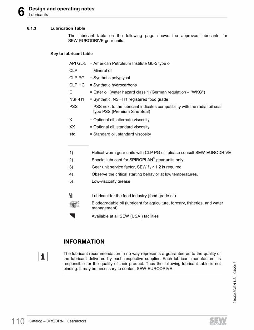
6.1.3 Lubrication Table Error! B ookmark not d efined .
The lubricant table on the following page shows the approved lubricants for SEW-EURODRIVE gear units.
Key to lubricant table
API GL-5 = American Petroleum Institute GL-5 type oil
CLP = Mineral oil
CLP PG = Synthetic polyglycol
CLP HC = Synthetic hydrocarbons
E = Ester oil (water hazard class 1 (German regulation – "WKG")
NSF-H1 = Synthetic, NSF H1 registered food grade
PSS = PSS next to the lubricant indicates compatibility with the radial oil seal type PSS (Premium Sine Seal)
X = Optional oil, alternate viscosity
XX = Optional oil, standard viscosity
std = Standard oil, standard viscosity
1) Helical-worm gear units with CLP PG oil: please consult SEW-EURODRIVE
2) Special lubricant for SPIROPLAN® gear units only
3) Gear unit service factor, SEW fB ≥ 1.2 is required
4) Observe the critical starting behavior at low temperatures.
5) Low-viscosity grease
Lubricant for the food industry (food grade oil)
Biodegradable oil (lubricant for agriculture, forestry, fisheries, and water management)
Available at all SEW (USA ) facilities
INFORMATION
The lubricant recommendation in no way represents a guarantee as to the quality of the lubricant delivered by each respective supplier. Each lubricant manufacturer is responsible for the quality of their product. Thus the following lubricant table is not binding. It may be necessary to contact SEW-EURODRIVE.
OilOil

6 Design and operating notesLubricants
6
Catalog – DRS/DRN.. Gearmotors 111
2193
3480
/EN
-US
– 0
4/20
18 Error! B ookmark not d efined .
Type
DIN
(ISO
)A
PI
ISO
SA
EN
LGI
RR
ES
FK
..7K
ES
/HK
S HS
Am
bie
nt T
emp
erat
ure
ºCN
ote
Op
timo
l
Mineral
CLP
VG
680
std
0+
40M
ob
ilgea
r 60
0X
P 6
80S
hell
Om
ala
S2
G 6
80K
lub
ero
ilG
EM
1-6
80 N
Ren
olin
S
EW
680
Op
tigea
r B
M 6
80C
arte
r E
P 6
80
VG
220
stan
dar
d-1
5+
40M
ob
ilgea
r 60
0X
P 2
20S
hell
Om
ala
S2
G 2
20K
lub
ero
ilG
EM
1-2
20 N
Ren
olin
C
LP 2
20O
ptig
ear
BM
220
Car
ter
EP
220
VG
150
X-2
0+
304)
Mo
bilg
ear
600
XP
150
She
ll O
mal
aS
2 G
150
Klu
ber
oil
GE
M 1
-150
NR
eno
lin
CLP
150
Op
tigea
r B
M 1
50C
arte
r E
P 1
50X
-20
+25
Synthetic
CLP HC
VG
460
XX
-15
+60
PSS
Mo
bil
SH
C 6
34S
hell
Om
ala
S4
GX
460
Klu
ber
synt
h G
EM
4-4
60 N
Ren
olin
Uni
syn
CLP
460
Op
tigea
r S
ynth
etic
P
D 4
60C
arte
r S
H 4
60
VG
220
XX
-25
+60
PSS
Mo
bil
SH
C 6
30S
hell
Om
ala
S4
GX
220
Klu
ber
synt
h G
EM
4-2
20 N
Ren
olin
Uni
syn
CLP
220
Op
tigea
r S
ynth
etic
PD
220
Car
ter
SH
220
VG
150
X-3
0+
704)
PSS
Mo
bil
SH
C 6
29S
hell
Om
ala
S4
GX
150
Klu
ber
synt
hG
EM
4-1
50 N
Ren
olin
Uni
syn
CLP
150
Op
tigea
r S
ynth
etic
PD
150
Car
ter
SH
150
X-3
0+
404)
VG
68
X-4
0+
204)
Mo
bil
SH
C 6
26S
hell
Om
ala
S4
GX
68
-R
eno
lin U
nisy
nC
LP 6
8-
-X
-40
+30
4)
VG
32
X-4
0+
204)
Mo
bil
SH
C 6
24-
-R
eno
lin U
nisy
n O
L32
-D
acni
s S
H 3
2X
-40
+10
4)
CLP PG
VG
680
X-1
5+
801)
Mo
bil
Gly
go
yle
680
She
ll O
mal
a S
4 W
E 6
80
PSS
Klu
ber
synt
hG
H 6
-680
Ren
olin
P
G 6
80O
ptig
ear
Syn
thet
ic80
0/68
0-
VG
220
X-2
5+
80M
ob
il G
lyg
oyl
e 22
0S
hell
Om
ala
S4
WE
220
PSS
Klu
ber
synt
hG
H 6
-220
Ren
olin
P
G 2
20O
ptig
ear
Syn
thet
ic80
0/22
0C
arte
r S
Y 2
20X
-25
+40
1)
CLP
HC
N
SF
-H1
VG
460
XX
XX
-15
+40
--
Klu
ber
oil
4UH
1-46
0 N
Cas
sid
a F
luid
GL
460
PSS
Op
tileb
GT
460
-
VG
220
XX
-25
+30
--
Klu
ber
oil
4UH
1-22
0 N
Cas
sid
a F
luid
GL
220
PSS
Op
tileb
GT
220
-
VG
68
X-3
5+
204)
--
Klu
ber
oil
4UH
1-68
NC
assi
da
Flu
id
HF
68
Op
tileb
HY
68
-X
-35
+10
4)
VG
32
X-4
0+
104)
--
Klu
ber
Sum
mit
HyS
yn F
G 3
2C
assi
da
Flu
id
HF
32
Op
tileb
HY
32
-X
-40
+0
4)
Bio
EV
G 4
60X
X-2
0+
40-
-K
lub
erb
ioC
A2-
460
Pla
nto
gea
r 46
0 S
--
Oil
Oil
TTO
T A
LO
T A
L
01 7
51 1
4 04
US1
Mo
bil
®

6 Design and operating notes Lubricants
Catalog – DRS/DRN.. Gearmotors 112
2193
3480
/EN
-US
– 0
4/20
18
Type
DIN
(ISO
)A
PI
ISO
SA
EN
LGI
K..9
W /
HW
Am
bie
nt T
emp
erat
ure
ºCN
ote
Op
timo
l
Synthetic
CLP
PG
VG
680
X-1
5+
80
PSS
Klu
ber
synt
hG
H 6
-680
VG
460
stan
dar
d-2
0+
60
PSS
Klu
ber
synt
hG
H 6
-460
stan
dar
d-2
0+
402)
Klu
ber
SE
WH
T 4
60-5
VG
220
X-2
5+
40
PSS
Klu
ber
synt
hG
H 6
-220
VG
150
X-3
0+
304)
PSS
Klu
ber
synt
hG
H 6
-150
CLP
PG
NS
F-H
1
VG
680
X-1
5+
80
PSS
Klu
ber
synt
hU
H1
6-68
0
VG
460
XX
-20
+60
PSS
Klu
ber
synt
hU
H1
6-46
0X
X-2
0+
603)
VG
220
X-2
5+
40
PSS
Klu
ber
synt
hU
H1
6-22
0
VG
150
X-3
0+
304)
PSS
Klu
ber
synt
hU
H1
6-15
0
AP
I GL5
VG
100
(SA
E 7
5W90
)X
-40
+30
4)M
ob
il S
ynth
G
ear
Oil
75W
90
TTO
T A
LO
T A
L
01 7
51 1
4 04
US2
Mo
bil
®

6 Design and operating notesOil fill quantities
6
Catalog – DRS/DRN.. Gearmotors 113
2193
3480
/EN
-US
– 0
4/20
18
6.1.4 Oil change frequency Error! B ookmark not d efined .
The following diagram shows the oil change frequency in normal ambient conditions for gear units listed in this catalog. The lubricant should be changed more frequently in severe conditions. Notice how synthetic oil (CLP HC, CLP PG) extends the maintenance interval 2 to 2.5 times longer than mineral oil. Thus, synthetic oil is highly recommended for hard-to-reach locations or applications where downtime is critical.
[1] Operating hours [2] Sustained oil bath temperature [3] Synthetic: CLP PG, CLP PG-NSF H1 [4] Synthetic: CLP HC, CLP HC-NSF H1 [5] Mineral: CLP, E
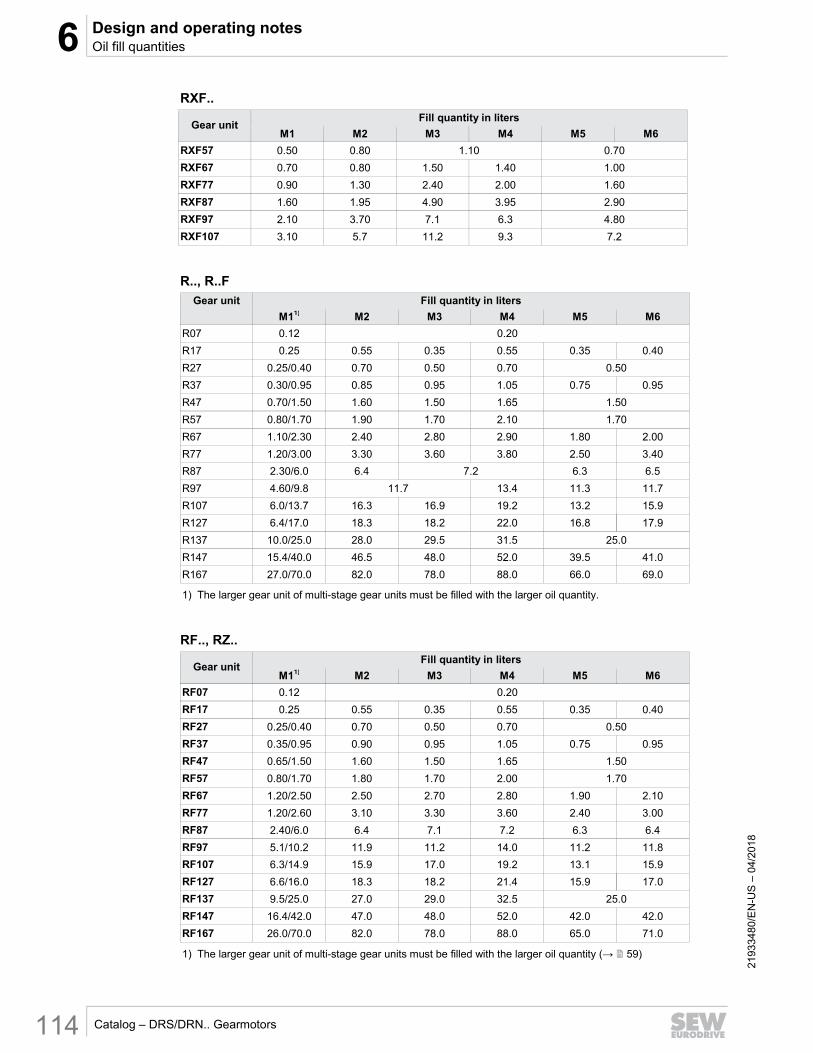
6.2 Oil fill quantities
INFORMATION
The specified fill quantities are only given as a guideline. The precise values vary depending on the number of stages and gear ratio. When filling, it is essential to check the oil level plug since it indicates the precise oil volume.
The following tables show lubricant fill quantities depending on the mounting positions M1 – M6.
Helical (R) gear units
RX..
Gear unit
Fill quantity in liters
M1 M2 M3 M4 M5 M6
RX57 0.60 0.80 1.30 0.90
RX67 0.80 1.70 1.90 1.10
RX77 1.10 1.50 2.60 2.70 1.60
RX87 1.70 2.50 4.80 2.90
RX97 2.10 3.40 7.4 7.0 4.80
RX107 3.90 5.6 11.6 11.9 7.7
6 Design and operating notes Oil fill quantities
Catalog – DRS/DRN.. Gearmotors 114
2193
3480
/EN
-US
– 0
4/20
18
RXF..
Gear unit
Fill quantity in liters
M1 M2 M3 M4 M5 M6
RXF57 0.50 0.80 1.10 0.70
RXF67 0.70 0.80 1.50 1.40 1.00
RXF77 0.90 1.30 2.40 2.00 1.60
RXF87 1.60 1.95 4.90 3.95 2.90
RXF97 2.10 3.70 7.1 6.3 4.80
RXF107 3.10 5.7 11.2 9.3 7.2
R.., R..F
Gear unit
Fill quantity in liters
M11) M2 M3 M4 M5 M6
R07 0.12 0.20
R17 0.25 0.55 0.35 0.55 0.35 0.40
R27 0.25/0.40 0.70 0.50 0.70 0.50
R37 0.30/0.95 0.85 0.95 1.05 0.75 0.95
R47 0.70/1.50 1.60 1.50 1.65 1.50
R57 0.80/1.70 1.90 1.70 2.10 1.70
R67 1.10/2.30 2.40 2.80 2.90 1.80 2.00
R77 1.20/3.00 3.30 3.60 3.80 2.50 3.40
R87 2.30/6.0 6.4 7.2 6.3 6.5
R97 4.60/9.8 11.7 13.4 11.3 11.7
R107 6.0/13.7 16.3 16.9 19.2 13.2 15.9
R127 6.4/17.0 18.3 18.2 22.0 16.8 17.9
R137 10.0/25.0 28.0 29.5 31.5 25.0
R147 15.4/40.0 46.5 48.0 52.0 39.5 41.0
R167 27.0/70.0 82.0 78.0 88.0 66.0 69.0
1) The larger gear unit of multi-stage gear units must be filled with the larger oil quantity.
RF.., RZ..
Gear unit
Fill quantity in liters
M11) M2 M3 M4 M5 M6
RF07 0.12 0.20
RF17 0.25 0.55 0.35 0.55 0.35 0.40
RF27 0.25/0.40 0.70 0.50 0.70 0.50
RF37 0.35/0.95 0.90 0.95 1.05 0.75 0.95
RF47 0.65/1.50 1.60 1.50 1.65 1.50
RF57 0.80/1.70 1.80 1.70 2.00 1.70
RF67 1.20/2.50 2.50 2.70 2.80 1.90 2.10
RF77 1.20/2.60 3.10 3.30 3.60 2.40 3.00
RF87 2.40/6.0 6.4 7.1 7.2 6.3 6.4
RF97 5.1/10.2 11.9 11.2 14.0 11.2 11.8
RF107 6.3/14.9 15.9 17.0 19.2 13.1 15.9
RF127 6.6/16.0 18.3 18.2 21.4 15.9 17.0
RF137 9.5/25.0 27.0 29.0 32.5 25.0
RF147 16.4/42.0 47.0 48.0 52.0 42.0 42.0
RF167 26.0/70.0 82.0 78.0 88.0 65.0 71.0
1) The larger gear unit of multi-stage gear units must be filled with the larger oil quantity (→ 59)
6 Design and operating notesOil fill quantities
6
Catalog – DRS/DRN.. Gearmotors 115
2193
3480
/EN
-US
– 0
4/20
18
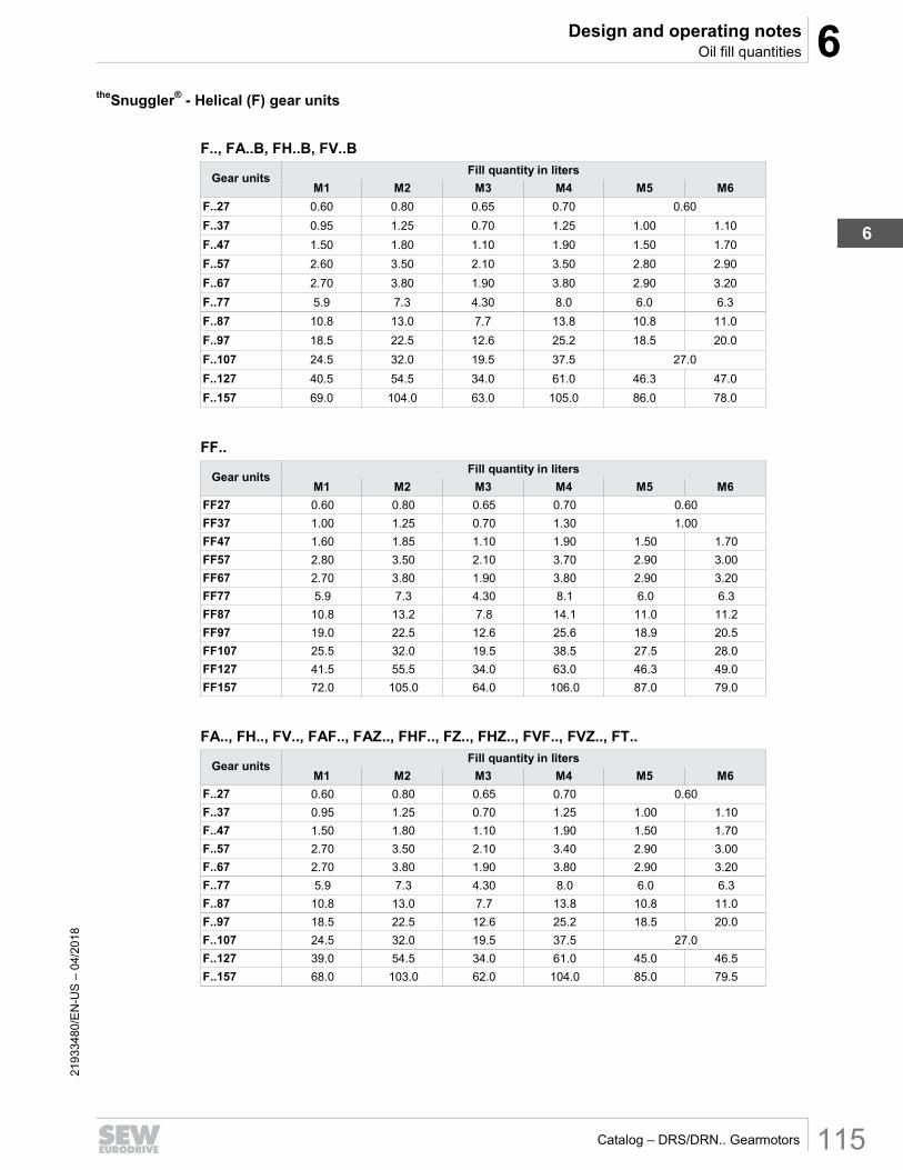
theSnuggler® - Helical (F) gear units
F.., FA..B, FH..B, FV..B
Gear units
Fill quantity in liters
M1 M2 M3 M4 M5 M6
F..27 0.60 0.80 0.65 0.70 0.60
F..37 0.95 1.25 0.70 1.25 1.00 1.10
F..47 1.50 1.80 1.10 1.90 1.50 1.70
F..57 2.60 3.50 2.10 3.50 2.80 2.90
F..67 2.70 3.80 1.90 3.80 2.90 3.20
F..77 5.9 7.3 4.30 8.0 6.0 6.3
F..87 10.8 13.0 7.7 13.8 10.8 11.0
F..97 18.5 22.5 12.6 25.2 18.5 20.0
F..107 24.5 32.0 19.5 37.5 27.0
F..127 40.5 54.5 34.0 61.0 46.3 47.0
F..157 69.0 104.0 63.0 105.0 86.0 78.0
FF..
Gear units
Fill quantity in liters
M1 M2 M3 M4 M5 M6
FF27 0.60 0.80 0.65 0.70 0.60
FF37 1.00 1.25 0.70 1.30 1.00
FF47 1.60 1.85 1.10 1.90 1.50 1.70
FF57 2.80 3.50 2.10 3.70 2.90 3.00
FF67 2.70 3.80 1.90 3.80 2.90 3.20
FF77 5.9 7.3 4.30 8.1 6.0 6.3
FF87 10.8 13.2 7.8 14.1 11.0 11.2
FF97 19.0 22.5 12.6 25.6 18.9 20.5
FF107 25.5 32.0 19.5 38.5 27.5 28.0
FF127 41.5 55.5 34.0 63.0 46.3 49.0
FF157 72.0 105.0 64.0 106.0 87.0 79.0
FA.., FH.., FV.., FAF.., FAZ.., FHF.., FZ.., FHZ.., FVF.., FVZ.., FT..
Gear units
Fill quantity in liters
M1 M2 M3 M4 M5 M6
F..27 0.60 0.80 0.65 0.70 0.60
F..37 0.95 1.25 0.70 1.25 1.00 1.10
F..47 1.50 1.80 1.10 1.90 1.50 1.70
F..57 2.70 3.50 2.10 3.40 2.90 3.00
F..67 2.70 3.80 1.90 3.80 2.90 3.20
F..77 5.9 7.3 4.30 8.0 6.0 6.3
F..87 10.8 13.0 7.7 13.8 10.8 11.0
F..97 18.5 22.5 12.6 25.2 18.5 20.0
F..107 24.5 32.0 19.5 37.5 27.0
F..127 39.0 54.5 34.0 61.0 45.0 46.5
F..157 68.0 103.0 62.0 104.0 85.0 79.5

6 Design and operating notes Oil fill quantities
Catalog – DRS/DRN.. Gearmotors 116
2193
3480
/EN
-US
– 0
4/20
18
Helical-bevel (K) gear units
INFORMATION
All K..19 and K..29 gear units are filled with the same oil quantity for all positions except M4. M4 requires a larger volume of oil.
K.., KA..B, KH..B, KV..B
Gear unit
Fill quantity in liters
M1 M2 M3 M4 M5 M6
K..19 0.40 0.45 0.40
K..29 0.70 0.85 0.70
K..39 0.90 1.70 1.55 1.9 1.55 1.30
K..49 1.70 3.40 2.80 4.20 3.15 2.80
K..37 0.50 1.00 1.25 0.95
K..47 0.80 1.30 1.50 2.00 1.60
K..57 1.10 2.20 2.80 2.30 2.10
K..67 1.10 2.40 2.60 3.45 2.60
K..77 2.20 4.10 4.40 5.80 4.20 4.40
K..87 3.70 8.0 8.70 10.90 8.0
K..97 7.0 14.0 15.70 20.0 15.70 15.50
K..107 10.0 21.0 25.50 33.50 24.0
K..127 21.0 41.50 44.0 54.0 40.0 41.0
K..157 31.0 65.0 68.0 90.0 62.0 63.0
K..167 33.0 97.0 109.0 127.0 89.0 86.0
K..187 53.0 156.0 174.0 207.0 150.0 147.0
KF..
Gear unit
Fill quantity in liters
M1 M2 M3 M4 M5 M6
KF19 0.40 0.45 0.40
KF29 0.70 0.85 0.70
KF39 0.90 1.70 1.55 1.9 1.55 1.30
KF49 1.70 3.40 2.80 4.20 3.15 2.80
KF37 0.50 1.10 1.50 1.00
KF47 0.80 1.30 1.70 2.20 1.60
KF57 1.20 2.20 2.40 3.15 2.50 2.30
KF67 1.10 2.40 2.80 3.70 2.70
KF77 2.10 4.10 4.40 5.90 4.50
KF87 3.70 8.20 9.0 11.90 8.40
KF97 7.0 14.70 17.30 21.50 15.70 16.50
KF107 10.0 21.80 25.80 35.10 25.20
KF127 21.0 41.50 46.0 55.0 41.0
KF157 31.0 66.0 69.0 92.0 62.0 63.0

6 Design and operating notesOil fill quantities
6
Catalog – DRS/DRN.. Gearmotors 117
2193
3480
/EN
-US
– 0
4/20
18
KA.., KH.., KV.., KAF.., KHF.., KVF.., KZ.., KAZ.., KHZ.., KVZ.., KT..
Gear unit
Fill quantity in liters
M1 M2 M3 M4 M5 M6
K..19 0.40 0.45 0.40
K..29 0.70 0.85 0.70
K..39 0.90 1.70 1.55 1.9 1.55 1.30
K..49 1.70 3.40 2.80 4.20 3.15 2.80
K..37 0.50 1.00 1.40 1.00
K..47 0.80 1.30 1.60 2.15 1.60
K..57 1.20 2.20 2.40 3.15 2.70 2.40
K..67 1.10 2.40 2.70 3.70 2.60
K..77 2.10 4.10 4.60 5.90 4.40
K..87 3.70 8.20 8.80 11.10 8.0
K..97 7.0 14.70 15.70 20.0 15.70
K..107 10.0 20.50 24.0 32.40 24.0
K..127 21.0 41.50 43.0 52.0 40.0
K..157 31.0 65.0 68.0 90.0 62.0 63.0
K..167 33.0 97.0 109.0 127.0 89.0 86.0
K..187 53.0 156.0 174.0 207.0 150.0 147.0

6 Design and operating notes Oil fill quantities
Catalog – DRS/DRN.. Gearmotors 118
2193
3480
/EN
-US
– 0
4/20
18
Helical-worm (S) gear units
S..
Gear unit
Fill quantity in liters
M1 M2 M31) M4 M5 M6
S37 0.25 0.40 0.50 0.55 0.40
S47 0.35 0.80 0.70/0.90 1.00 0.80
S57 0.50 1.20 1.00/1.20 1.45 1.30
S67 1.00 2.00 2.20/3.10 3.10 2.60 2.60
S77 1.90 4.20 3.70/5.4 5.9 4.40
S87 3.30 8.1 6.9/10.4 11.3 8.4
S97 6.8 15.0 13.4/18.0 21.8 17.0
1) The larger gear unit of multi-stage gear units must be filled with the larger oil quantity.
SF..
Gear unit
Fill quantity in liters
M1 M2 M31) M4 M5 M6
SF37 0.25 0.40 0.50 0.55 0.40
SF47 0.40 0.90 0.90/1.05 1.05 1.00
SF57 0.50 1.20 1.00/1.50 1.55 1.40
SF67 1.00 2.20 2.30/3.00 3.20 2.70
SF77 1.90 4.10 3.90/5.8 6.5 4.90
SF87 3.80 8.0 7.1/10.1 12.0 9.1
SF97 7.4 15.0 13.8/18.8 22.6 18.0
1) The larger gear unit of multi-stage gear units must be filled with the larger oil quantity.
SA.., SH.., SAF.., SHZ.., SAZ.., SHF.., ST..
Gear unit
Fill quantity in liters
M1 M2 M31) M4 M5 M6
S..37 0.25 0.40 0.50 0.40
S..47 0.40 0.80 0.70/0.90 1.00 0.80
S..57 0.50 1.10 1.00/1.50 1.50 1.20
S..67 1.00 2.00 1.80/2.60 2.90 2.50
S..77 1.80 3.90 3.60/5.0 5.8 4.50
S..87 3.80 7.4 6.0/8.7 10.8 8.0
S..97 7.0 14.0 11.4/16.0 20.5 15.7
1) The larger gear unit of multi-stage gear units must be filled with the larger oil quantity.

6 Design and operating notesGear unit venting
6
Catalog – DRS/DRN.. Gearmotors 119
2193
3480
/EN
-US
– 0
4/20
18
SPIROPLAN® (W) gear units
INFORMATION
SPIROPLAN® gear units W..10 to W..30 have a universal mounting position. Therefore, they are filled with the same oil quantity regardless of the mounting position.
The oil fill quantity of SPIROPLAN® gear units W..37 and W..47 in mounting position M4 is different than the amount needed for the other mounting positions.
W.., WA..B, WH..B
Gear unit
Fill quantity in liters
M1 M2 M3 M4 M5 M6
W..10 0.16
W..20 0.24
W..30 0.40
W..37 0.50 0.70 0.50
W..47 0.90 1.40 0.90
WF..
Gear unit
Fill quantity in liters
M1 M2 M3 M4 M5 M6
WF10 0.16
WF20 0.24
WF30 0.40
WF37 0.50 0.70 0.50
WF47 0.90 1.55 0.90
WA.., WAF..,WH.., WT.., WHF..
Gear unit
Fill quantity in liters
M1 M2 M3 M4 M5 M6
W..10 0.16
W..20 0.24
W..30 0.40
W..37 0.50 0.70 0.50
W..47 0.80 1.40 0.80
6.3 Gear unit venting Error! B ookmark not d efined .
INFORMATION
The function of breather valves can be impaired by dirt and dust in the environment.
If necessary, contact SEW-EURODRIVE to discuss alternative venting systems.

6 Design and operating notes Reduced backlash /R
Catalog – DRS/DRN.. Gearmotors 120
2193
3480
/EN
-US
– 0
4/20
18
6.4 Reduced backlash /R Error! B ookmark not d efined .Error! Boo kmark not defin ed .
The rotational clearance (backlash) of units with this option is considerably less than that of the standard designs; therefore, positioning tasks can be solved with great precision. The rotational clearance for the output shaft is specified without load (max. 1% of the rated output torque) with the gear unit input end blocked. The clearance is specified in angular minutes and is shown in the "Possible geometrical combinations" section within each gear unit chapter.
The reduced backlash design is available for the following gear units:
• Helical gear units (R), sizes 37 to 167
• theSnuggler® helical gear units (F), sizes 37 to 157
• Helical-bevel gear units (K..7), sizes 37 to 187.
Reduced backlash is not available on K..9 gear units or compound gear units.
The dimensions of the reduced backlash designs are the same as the dimensions of the standard designs, except for theSnuggler® helical gear units FH.87 and FH.97. The following figure shows the reduced backlash dimensions of FH.87 and FH.97.
6644506891
Type Dimensions in mm
D6 D7 G4 M4 M5 M6 M7 O1 O8
FH.87/R Ø 65 h6 Ø 85 Ø 163 41 40 46 45 312.5 299.5
FH.97/R Ø 75 h6 Ø 95 Ø 184 55 50 60 55 382.5 367

6 Design and operating notesInstallation/removal of gear units with hollow shaft and key
6
Catalog – DRS/DRN.. Gearmotors 121
2193
3480
/EN
-US
– 0
4/20
18
6.5 Installation/removal of gear units with hollow shaft and key Error! B ookmark not d efined .Error! Boo kmark not defin ed .Error! Boo kmark not d efin ed.Erro r! Boo kmark not d efin ed.
INFORMATION
Use the supplied NOCO® fluid for assembly. The fluid minimizes contact corrosion and facilitates future disassembly (→ 19).
6.5.1 Design Methods
There are two ways to design the customer’s solid shaft for use with a gear unit containing a keyed hollow shaft. While both designs are acceptable, the second is more advantageous to the end user because it allows for easier disassembly later, especially if corrosion exists between the two shafts.
1. Standard Design:
Use the fastening parts supplied with the gear unit. This design requires a longer customer shaft that extends to the snapring. While this design is very common, it does not permit the use of a removal kit to aid with future removal of the customer’s shaft.
2. Recommended Design:
Use the optional installation/removal kit. This design requires a shorter customer shaft than the standard design. The shaft does not extend to the snapring. The area between the end of the shaft and the snapring contains a gap or a spacer tube, depending if the customer shaft contains a shoulder. During future disassembly, the gap or spacer tube is replaced with a locking nut that allows the user to push out the shaft by turning a wrench. This is especially beneficial in a humid or wet environment where corrosion between the shafts is probable.

6 Design and operating notes Installation/removal of gear units with hollow shaft and key
Catalog – DRS/DRN.. Gearmotors 122
2193
3480
/EN
-US
– 0
4/20
18
6.5.2 Standard Design
The standard design uses the parts that are normally supplied with every hollow shaft, as shown in Figure 1 below. Note the following points concerning the customer’s solid shaft.
• See dimension sheets or next page for dimension, L8
• If there is a contact shoulder [A] on the customer shaft, the installation length should be (L8 - 1 mm) or (L8 - 0.04 in).
• If there is no contact shoulder [B] on the customer shaft, the installation length should equal L8.
• Observe the tolerances for dimension, D, along the shaft.
• Refer to the dimension pages (or next page) for the diameter and length of retaining screw [2].
• X must be > D. But the key does not have to extend the length of shaft.
Figure 1: Customer shaft with contact shoulder [A] and without contact shoulder [B]
[1] Hollow shaft [5] Flat washer
[2] Retaining screw [6] Lock washer
[3] Retaining snapring [7] Plastic protection cap
[4] Customer solid shaft
[1] [2][3][4] [1] [4] [3] [2]
[5] [5][6] [6]
00 001 00 02US
0.5 x D 0.5 x D
1.5 x DL8
1.5 x D
Dh6
Dg6 Dh6
Dg6
D D
[A] with shoulder [B] without shoulder(L8 - 1mm)

6 Design and operating notesInstallation/removal of gear units with hollow shaft and key
6
Catalog – DRS/DRN.. Gearmotors 123
2193
3480
/EN
-US
– 0
4/20
18
Customer shaft dimensions – Standard design
[inch] [mm]
Gear Unit D STD Screw L81 D STD Screw L81)
WA..10 0.625 1/4-20 x 5/8 2.72 14 or 16 M5 x 16 69
KA..19 0.750 1/4-20 x 5/8 3.62 20 M6 x 16 92
WA..20 0.750 1/4-20 x 5/8 3.31 18
M6 x 16 84 20
FA..27 1.000 3/8-16 x 1 3.47 25 M10 x 25 88
KA..29 1.000 3/8-16 x 1 4.21 25 M10 x 25 107
WA..30, WA..37 0.750 1/4-20 x 5/8 4.13 20 M6 x 16 105
SA..37 0.750 1/4-20 x 5/8 4.09 20 M6 x 16 104
FA..37, KA..37 1.250 7/16-14 x 1 4.13 30 M10 x 25 105
KA..39 1.250 7/16-14 x 1
5.39 30 M10 x 25
137 1.375 1/2-13 x 1 35 M12 x 30
WA..47 1.000 3/8-16 x 1
4.80 30 M10 x 25 122 1.250 7/16-14 x 1
SA..47 1.250 7/16-14 x 1 4.13 25
M10 x 25 105 30
FA..47, KA..47, SA..57
1.250 7/16-14 x 1
5.20
30 M10 x 25
132 1.375 1/2-13 x 1 35 M12 x 30
1.4375 5/8-11 x 1-3/4
KA..49 1.375 1/2-13 x 1
6.30 35 M12 x 30
160 1.500 5/8-11 x 1-3/4 40 M16 x 40
FA..57, KA..57 1.4375
5/8-11 x 1-3/4 5.59 40 M16 x 40 142 1.500
FA..67, KA..67 1.4375
5/8-11 x 1-3/4 6.14 40 M16 x 40 156 1.500
SA..67 1.250 7/16-14 x 1
5.67 40
M16 x 40 144 1.500 5/8-11 x 1-3/4 45
FA..77, KA..77 1.9375
5/8-11 x 1-3/4 7.21 50 M16 x 45 183 2.000
SA..77 2.000 5/8-11 x 1-3/4 7.21 50 M16 x 45 183
7.09 60 M20 x 50 180
FA..87, KA..87 2.375
3/4-10 x 2 8.27 60 M20 x 50 210 2.4375
SA..87 2.375 3/4-10 x 2 8.66 60
M20 x 50 220 70
FA..97, KA..97 2.750
3/4-10 x 2 10.63 70 M20 x 50 270 2.9375
SA..97 2.750 3/4-10 x 2 10.24 70 M20 x 50 260
10.04 90 M24 x 60 255
FA..107, KA..107
3.250
3/4-10 x 2 12.32
90 M24 x 60
313 3.4375 80 M20 x 50
3.625
FA..127, KA..127 4.000 1-8 x 2-1/4
14.69 100 M24 x 60
373
FA..157, KA..157 4.500 18.11 120 460
1If customer shaft does not contain a shoulder, then the installation length of customer shaft = L8. If customer shaft contains a shoulder, the installation length = (L8 - 1mm) or (L8 - 0.04")

6 Design and operating notes Installation/removal of gear units with hollow shaft and key
Catalog – DRS/DRN.. Gearmotors 124
2193
3480
/EN
-US
– 0
4/20
18
Installation procedure – standard design
1. Apply and thoroughly spread NOCO fluid (normally supplied with unit).
2. Install the shaft and secure it axially with the hardware supplied.
[2] Shorter retaining screw (normally supplied) [5] Flat washer
[3] Retaining snapring [6] Lock washer
[4] Customer shaft
3. Tighten the retaining screw to the appropriate torque shown in the table below.
211516171
211518347US
211524875
Tightening torqueNm / lb-in
M5 5 / 44
M6 8 / 71
M1020 / 177
M16 40 / 355
M20 80 / 710
M24 200 / 1770
Screw
1/4-20
7/16-14
5/8-11
3/4-10
1-8
1/2-13M12
Metric SAE

6 Design and operating notesInstallation/removal of gear units with hollow shaft and key
6
Catalog – DRS/DRN.. Gearmotors 125
2193
3480
/EN
-US
– 0
4/20
18
6.5.3 Recommended design
The recommended design uses the standard hardware along with a removal kit, as shown dotted in Figure 2 below. However, the normal retaining screw is too short; therefore, the removal kit includes a longer screw [2]. The customer may make his own kit or purchase it from SEW-EURODRIVE. Kit part numbers and dimensions are shown on page 127.
Please observe the following:
• Items 3, 5, 6, and 7 are normally supplied with the hollowshaft, so they are not included in the kit
• The longer retaining screw [2] can be used for both assembly and removal.
• The installation length of the customer shaft must be LK2, regardless if the shaft has a contact shoulder or not. See next page for LK2 dimension. Observe that the customer shaft does not extend to the snapring.
• The spacer tube [8] is not needed if the customer shaft has a shoulder.
• X must be > D. However, the key does not have to extend the length of shaft.
Figure 2: Customer shaft with contact shoulder [A] and without contact shoulder [B]
[1] Hollow shaft [6] Lock washer
[2] Retaining screw (for assembly & removal) [7] Plastic protection cap
[3] Retaining snapring [8] Space tube (not needed w/shoulder)
[4] Customer solid shaft [9] Locking nut (for removal only)
[5] Flat washer [10] Forcing washer (for removal only)
[1] [2][3][4] [1] [4] [3] [2]
[5]
[A] with shoulder [B] without shoulder
[6]
[8]
[5][6]
00 002 00 02US
6 Design and operating notes Installation/removal of gear units with hollow shaft and key
Catalog – DRS/DRN.. Gearmotors 126
2193
3480
/EN
-US
– 0
4/20
18
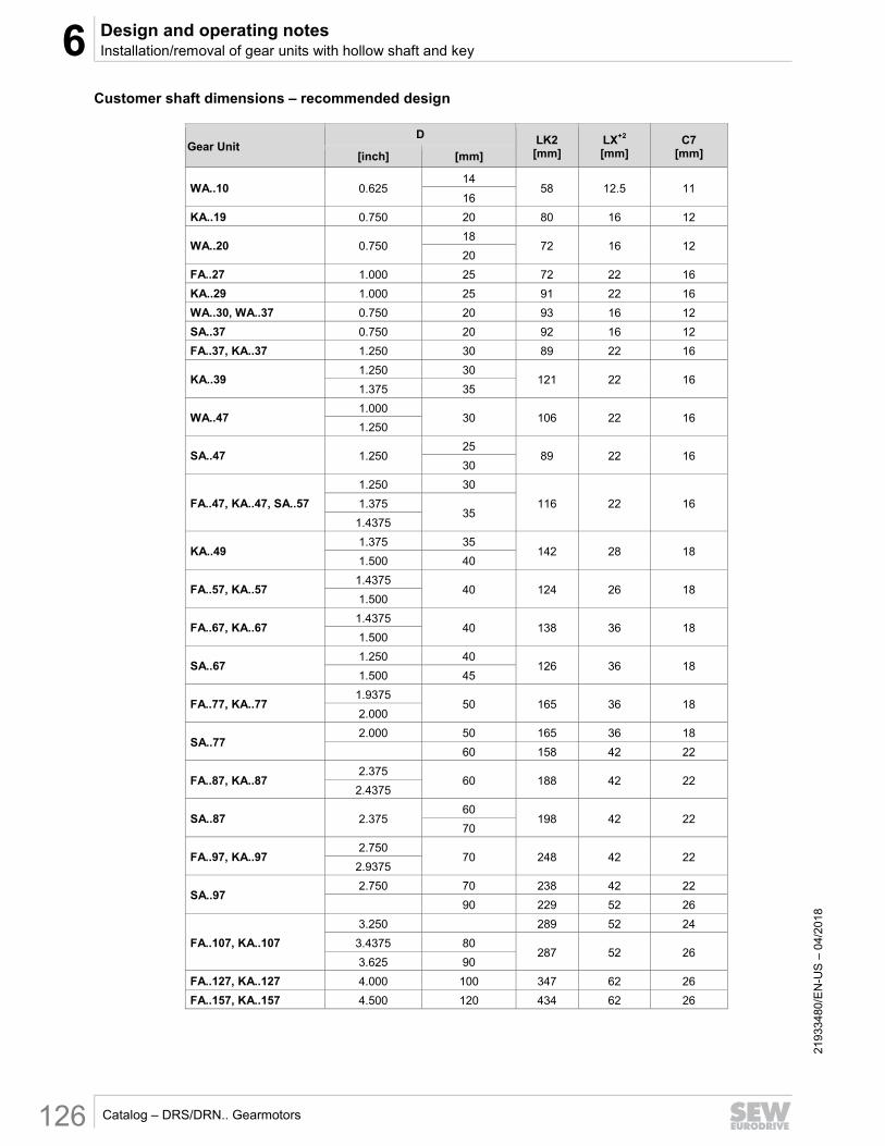
Customer shaft dimensions – recommended design
Gear Unit D LK2
[mm] LX+2 [mm]
C7 [mm] [inch] [mm]
WA..10 0.625 14
58 12.5 11 16
KA..19 0.750 20 80 16 12
WA..20 0.750 18
72 16 12 20
FA..27 1.000 25 72 22 16
KA..29 1.000 25 91 22 16
WA..30, WA..37 0.750 20 93 16 12
SA..37 0.750 20 92 16 12
FA..37, KA..37 1.250 30 89 22 16
KA..39 1.250 30
121 22 16 1.375 35
WA..47 1.000
30 106 22 16 1.250
SA..47 1.250 25
89 22 16 30
FA..47, KA..47, SA..57
1.250 30
116 22 16 1.375 35
1.4375
KA..49 1.375 35
142 28 18 1.500 40
FA..57, KA..57 1.4375
40 124 26 18 1.500
FA..67, KA..67 1.4375
40 138 36 18 1.500
SA..67 1.250 40
126 36 18 1.500 45
FA..77, KA..77 1.9375
50 165 36 18 2.000
SA..77 2.000 50 165 36 18
60 158 42 22
FA..87, KA..87 2.375
60 188 42 22 2.4375
SA..87 2.375 60
198 42 22 70
FA..97, KA..97 2.750
70 248 42 22 2.9375
SA..97 2.750 70 238 42 22
90 229 52 26
FA..107, KA..107
3.250 289 52 24
3.4375 80 287 52 26
3.625 90
FA..127, KA..127 4.000 100 347 62 26
FA..157, KA..157 4.500 120 434 62 26

6 Design and operating notesInstallation/removal of gear units with hollow shaft and key
6
Catalog – DRS/DRN.. Gearmotors 127
2193
3480
/EN
-US
– 0
4/20
18
Kit dimensions and part numbers
[2] Longer retaining screw
[9] Locking nut
[10] Forcing washer
D [mm]
M C4
[mm] C5
[mm] C6
[mm] U-0.5
[mm] T -0.5 [mm]
D3-0.5 [mm]
L4 [mm]
Kit Part Number
16 M5
5
5 12 4.5 18 15.7 50 643 712 5
18 M6 6
13.5 5.5 20.5 17.7 25
643 682 X
20 15.5 5.5 22.5 19.7 643 683 8
25 M10 10
20 7.5 28 24.7 35
643 684 6
30 25 7.5 33 29.7 643 685 4
35 M12
12
29 9.5 38 34.7 45 643 686 2
40
M16
34 11.5 41.9 39.7
50
643 687 0
45 38.5 13.5 48.5 44.7 643 688 9
50 43.5 13.5 53.5 49.7 643 689 7
60 M20 16
56 17.5 64 59.7 60
643 690 0
70 65.5 19.5 74.5 69.7 643 691 9
90
M24 20
80 24.5 95 89.7
70
643 692 7
100 89 27.5 106 99.7 643 693 5
120 107 31 127 119.7 643 694 3
D
[inch] M
C4 [mm]
C5 [mm]
C6 [inch]
U-0.02 [inch]
T -0.02 [inch]
D3-0.02 [inch]
L4 [inch]
Kit Part Number
0.625 1/4-20
5
5 0.500 0.168
0.701 0.6130 2.0 250 546 00
0.750 1/4-20 6 0.625 0.835 0.738 1.0 250 546 19
1.000 7/16-14 10
0.863 0.230
1.110 0.988 1.5
250 546 27
1.250 7/16-14 1.113 1.362 1.238 250 546 35
1.375 1/2-13
12
1.142 0.293 1.509 1.363 1.75 250 546 43
1.4375 5/8-11 1.205 0.356
1.602 1.4255
2.0
250 546 51
1.500 5/8-11 1.267 1.657 1.4880 250 546 78
1.9375 5/8-11 1.682 0.480
2.148 1.9255 250 546 86
2.00 5/8-11 1.744 2.224 1.9880 250 546 94
2.375 3/4-10
16
2.119
0.606
2.650 2.3630
2.5
250 247 08
2.4375 3/4-10 2.182 2.605 2.4255 250 547 16
2.750 3/4-10 2.488 3.031 2.7380 250 547 24
2.9375 3/4-10 18
2.676 0.730
3.128 2.9255
3.0
250 547 32
3.250 3/4-10 2.938 3.587 3.2380 250 547 40
3.4375 3/4-10
20
3.126 0.856 3.685 3.4255 250 547 59
3.6250 1-8 3.263 0.856 3.873 3.6130 250 547 67
4.000 1-8 3.588 0.980
4.441 3.9880 3.5
250 547 75
4.500 1-8 4.088 4.933 4.4880 250 547 83
[2]
[10] [9]
Shaft shoulder (if used)
D3
C6

6 Design and operating notes Installation/removal of gear units with hollow shaft and key
Catalog – DRS/DRN.. Gearmotors 128
2193
3480
/EN
-US
– 0
4/20
18
Installation procedure – recommended design
1. Apply and thoroughly spread NOCO fluid (normally supplied with unit).
2. Install the shaft and secure it axially with the hardware supplied.
[2] Longer retaining screw [5] Flat washer
[3] Retaining snapring [6] Lock washer
[4] Customer shaft [8] Spacer tube
3. Tighten the retaining screw to the appropriate torque shown in the table below.
211516171
211520523US
With shaftshoulder
Without shaftshoulder
211524875
Tightening torqueNm / lb-in
M5 5 / 44
M6 8 / 71
M1020 / 177
M16 40 / 355
M20 80 / 710
M24 200 / 1770
Screw
1/4-20
7/16-14
5/8-11
3/4-10
1-8
1/2-13M12
Metric SAE

6 Design and operating notesInstallation/removal of gear units with hollow shaft and key
6
Catalog – DRS/DRN.. Gearmotors 129
2193
3480
/EN
-US
– 0
4/20
18
Removal procedure – recommended design
[2] Longer retaining screw [6] Lock washer
[3] Snapring [8] Spacer tube
[4] Customer shaft [9] Locking nut
[5] Flat washer [10] Forcing washer
1. Loosen the retaining screw [2].
2. Remove parts [3], [5], and [6]. Also, remove the spacer tube, [8], if applicable.
3. Using the parts [9] and [10] from the removal kit, insert the forcing washer and the locking nut until they rest against the customer shaft [4].
4. Re-install the snapring [3].
5. Thread the retaining screw [2] into the locking nut as shown below.
6. Continue turning the screw with wrench to force the shaft out of the gear unit, as shown in the cross sectional view below.
211527051US

6 Design and operating notes Chamfers on hollow shafts
Catalog – DRS/DRN.. Gearmotors 130
2193
3480
/EN
-US
– 0
4/20
18
6.6 Chamfers on hollow shafts Error! B ookmark not d efined .
The following illustration shows the chamfers on gear units with hollow shaft:
4309448843
Gear unit Design
Hollow shaft (A) Hollow shaft and shrink disk (H)
W..10 1.5 × 30° -
W..20
2 × 30°
-
W..30 -
F..27
0.5 × 45° K..19
K..29
F../K../S../W..37
K..39 -
F../K../S../ W..47 0.5 × 45°
K..49 -
S..57
0.5 × 45°
F../K..57
F../K../S..67
F../K../S..77
F../K../S..87
3 × 30° F../K../S..97
F../K..107
F../K..127 5 × 30°
F../K..157
KH167 -
KH187 -
6.6.1 Special motor/gear unit combinations Error! B ookmark not d efined .
Please note for theSnuggler® (F-series) gearmotors with hollow shaft (FA..B, FV..B, FH..B, FAF, FVF, FHF, FA, FV, FH, FT, FAZ, FVZ, FHZ):
• If the machine shaft enters the gear unit from underneath the motor, there may be interference on some gear unit/motor combinations, especially with larger motors.
• Check the motor dimension AC to determine if there is interference when the customer shaft is pushed through.

6 Design and operating notesTorqLOC® mounting system for hollow shaft gear units
6
Catalog – DRS/DRN.. Gearmotors 131
2193
3480
/EN
-US
– 0
4/20
18
6.7 TorqLOC® mounting system for hollow shaft gear units Error! B ookmark not d efined .
The TorqLOC® hollow shaft mounting system is a premier design used for achieving a keyless connection between a customer solid shaft and the hollow shaft of the gear unit. TorqLOC® is the preferred alternative to a hollow shaft with shrink disk, a hollow shaft with key, or a hollow shaft with spline.
TorqLOC® consists of the following components:
4309625867
[1] Customer shaft [5] Shrink disk
[2] Clamping ring [6] Tapered bushing (steel or stainless steel)
[3] Tapered bronze bushing [7] Fixed hood cover
[4] Hollow shaft inside gear unit
6.7.1 Benefits of TorqLOC®
The TorqLOC® hollow shaft mounting system provides the following benefits:
• Cost savings because the customer shaft can be made from turned shaft stock or cold rolled stock without additional machining (material up to quality h11).
• Cost savings because there is no keyway to machine.
• A variety of tapered bushings [item 6] are available for each hollow shaft, providing flexibility and various shaft diameter options within the same gear unit.
• Simple installation since there is no key.
• Simple removal even after many hours of operation. High clamping forces on one end and dissimilar metals on the other end deter corrosion.
• Ease of disassembly - the same screws that are used for tightening during installation can be used for future disassembly.
6
5
4
3
2
1
7
6 Design and operating notes TorqLOC® mounting system for hollow shaft gear units
Catalog – DRS/DRN.. Gearmotors 132
2193
3480
/EN
-US
– 0
4/20
18
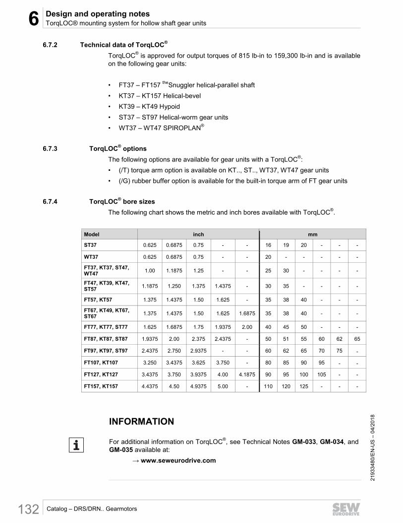
6.7.2 Technical data of TorqLOC®
TorqLOC® is approved for output torques of 815 lb-in to 159,300 lb-in and is available on the following gear units:
• FT37 – FT157 theSnuggler helical-parallel shaft
• KT37 – KT157 Helical-bevel
• KT39 – KT49 Hypoid
• ST37 – ST97 Helical-worm gear units
• WT37 – WT47 SPIROPLAN®
6.7.3 TorqLOC® options
The following options are available for gear units with a TorqLOC®:
• (/T) torque arm option is available on KT.., ST.., WT37, WT47 gear units
• (/G) rubber buffer option is available for the built-in torque arm of FT gear units
6.7.4 TorqLOC® bore sizes
The following chart shows the metric and inch bores available with TorqLOC®.
Model inch mm
ST37 0.625 0.6875 0.75 - - 16 19 20 - - -
WT37 0.625 0.6875 0.75 - - 20 - - - - -
FT37, KT37, ST47, WT47
1.00 1.1875 1.25 - - 25 30 - - - -
FT47, KT39, KT47, ST57
1.1875 1.250 1.375 1.4375 - 30 35 - - - -
FT57, KT57 1.375 1.4375 1.50 1.625 - 35 38 40 - - -
FT67, KT49, KT67, ST67 1.375 1.4375 1.50 1.625 1.6875 35 38 40 - - -
FT77, KT77, ST77 1.625 1.6875 1.75 1.9375 2.00 40 45 50 - - -
FT87, KT87, ST87 1.9375 2.00 2.375 2.4375 - 50 51 55 60 62 65
FT97, KT97, ST97 2.4375 2.750 2.9375 - - 60 62 65 70 75 -
FT107, KT107 3.250 3.4375 3.625 3.750 - 80 85 90 95 - -
FT127, KT127 3.4375 3.750 3.9375 4.00 4.1875 90 95 100 105 - -
FT157, KT157 4.4375 4.50 4.9375 5.00 - 110 120 125 - - -
INFORMATION
For additional information on TorqLOC®, see Technical Notes GM-033, GM-034, and GM-035 available at:
→ www.seweurodrive.com

6 Design and operating notesShouldered hollow shaft with shrink disk
6
Catalog – DRS/DRN.. Gearmotors 133
2193
3480
/EN
-US
– 0
4/20
18
6.8 Shouldered hollow shaft with shrink disk Error! B ookmark not d efined .
The following gear units with a hollow shaft and shrink disk are also available with an optional larger bore diameter D':
• Parallel-shaft helical gear units FH/FHF/FHZ37 – 157
• Helical-bevel gear units KH/KHF/KHZ37 – 157
• Helical-worm gear units SH/SHF47 – 97
D' = D as standard.
4987055371
Gear units Bore diameter
D / optionally D’
mm
FH/FHF/FHZ37, KH/KHF/KHZ37, SH/SHF/SHZ47 30 / 32
FH/FHF/FHZ47, KH/KHF/KHZ47, SH/SHF/SHZ57 35 / 36
FH/FHF/FHZ57, KH/KHF/KHZ57 40 / 42
FH/FHF/FHZ67, KH/KHF/KHZ67, SH/SHF/SHZ67 40 / 42
FH/FHF/FHZ77, KH/KHF/KHZ77, SH/SHF/SHZ77 50 / 52
FH/FHF/FHZ87, KH/KHF/KHZ87, SH/SHF/SHZ87 65 / 66
FH/FHF/FHZ97, KH/KHF/KHZ97, SH/SHF/SHZ97 75 / 76
FH/FHF/FHZ107, KH/KHF/KHZ107 95 / 96
FH/FHF/FHZ127, KH/KHF/KHZ127 105 / 106
FH/FHF/FHZ157, KH/KHF/KHZ157 125 / 126
Diameter D / D’ must be specified when ordering gear units with a shouldered hollow shaft (optional bore diameter D’).
6.8.1 Sample order
FH37 DRN80M4 with hollow shaft 30/32 mm
D D'
D D'
6 Design and operating notes Shouldered hollow shaft with shrink disk
Catalog – DRS/DRN.. Gearmotors 134
2193
3480
/EN
-US
– 0
4/20
18
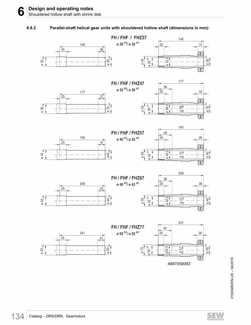
6.8.2 Parallel-shaft helical gear units with shouldered hollow shaft (dimensions in mm): Error! B ookmark not d efined .
4987059083

6 Design and operating notesShouldered hollow shaft with shrink disk
6
Catalog – DRS/DRN.. Gearmotors 135
2193
3480
/EN
-US
– 0
4/20
18
4987060747
6 Design and operating notes Shouldered hollow shaft with shrink disk
Catalog – DRS/DRN.. Gearmotors 136
2193
3480
/EN
-US
– 0
4/20
18
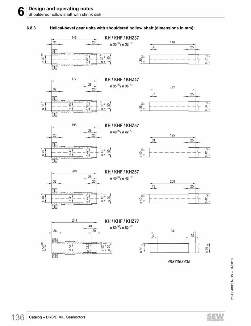
6.8.3 Helical-bevel gear units with shouldered hollow shaft (dimensions in mm): Error! B ookmark not d efined .
4987063435

6 Design and operating notesShouldered hollow shaft with shrink disk
6
Catalog – DRS/DRN.. Gearmotors 137
2193
3480
/EN
-US
– 0
4/20
18
4987065099

6 Design and operating notes Shouldered hollow shaft with shrink disk
Catalog – DRS/DRN.. Gearmotors 138
2193
3480
/EN
-US
– 0
4/20
18
6.8.4 Helical-worm gear units with shouldered hollow shaft (dimensions in mm): Error! B ookmark not d efined .
4987067787

6 Design and operating notesShouldered hollow shaft with shrink disk
6
Catalog – DRS/DRN.. Gearmotors 139
2193
3480
/EN
-US
– 0
4/20
18
4987069451
6 Design and operating notes Covers for hollow shafts
Catalog – DRS/DRN.. Gearmotors 140
2193
3480
/EN
-US
– 0
4/20
18
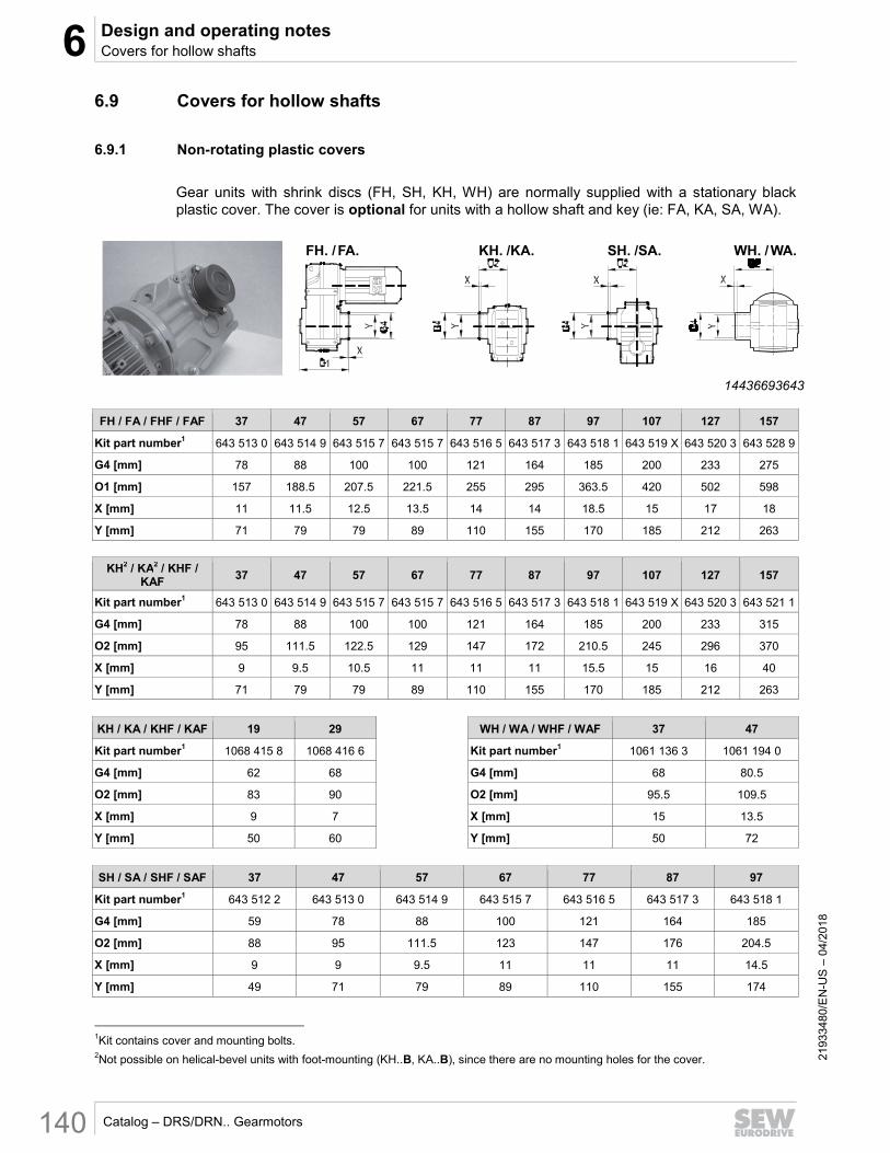
6.9 Covers for hollow shafts Error! B ookmark not d efined .
6.9.1 Non-rotating plastic covers Error! B ookmark not d efined .
Gear units with shrink discs (FH, SH, KH, WH) are normally supplied with a stationary black plastic cover. The cover is optional for units with a hollow shaft and key (ie: FA, KA, SA, WA).
14436693643
FH / FA / FHF / FAF 37 47 57 67 77 87 97 107 127 157
Kit part number1 643 513 0 643 514 9 643 515 7 643 515 7 643 516 5 643 517 3 643 518 1 643 519 X 643 520 3 643 528 9
G4 [mm] 78 88 100 100 121 164 185 200 233 275
O1 [mm] 157 188.5 207.5 221.5 255 295 363.5 420 502 598
X [mm] 11 11.5 12.5 13.5 14 14 18.5 15 17 18
Y [mm] 71 79 79 89 110 155 170 185 212 263
KH2 / KA2 / KHF / KAF
37 47 57 67 77 87 97 107 127 157
Kit part number1 643 513 0 643 514 9 643 515 7 643 515 7 643 516 5 643 517 3 643 518 1 643 519 X 643 520 3 643 521 1
G4 [mm] 78 88 100 100 121 164 185 200 233 315
O2 [mm] 95 111.5 122.5 129 147 172 210.5 245 296 370
X [mm] 9 9.5 10.5 11 11 11 15.5 15 16 40
Y [mm] 71 79 79 89 110 155 170 185 212 263
KH / KA / KHF / KAF 19 29 WH / WA / WHF / WAF 37 47
Kit part number1 1068 415 8 1068 416 6 Kit part number1 1061 136 3 1061 194 0
G4 [mm] 62 68 G4 [mm] 68 80.5
O2 [mm] 83 90 O2 [mm] 95.5 109.5
X [mm] 9 7 X [mm] 15 13.5
Y [mm] 50 60 Y [mm] 50 72
SH / SA / SHF / SAF 37 47 57 67 77 87 97
Kit part number1 643 512 2 643 513 0 643 514 9 643 515 7 643 516 5 643 517 3 643 518 1
G4 [mm] 59 78 88 100 121 164 185
O2 [mm] 88 95 111.5 123 147 176 204.5
X [mm] 9 9 9.5 11 11 11 14.5
Y [mm] 49 71 79 89 110 155 174
1Kit contains cover and mounting bolts. 2Not possible on helical-bevel units with foot-mounting (KH..B, KA..B), since there are no mounting holes for the cover.
FH. /FA. KH. /KA. SH. /SA. WH. /WA.

6 Design and operating notesCovers for hollow shafts
6
Catalog – DRS/DRN.. Gearmotors 141
2193
3480
/EN
-US
– 0
4/20
18
6.9.2 Non-rotating metal covers Error! B ookmark not d efined .
Gear units with TorqLOC (FT, ST, KT, WT) are normally supplied with a stainless steel cover and seal. This cover is optional on units with a hollow shaft and key or units with shrink disc. Note that on some combinations of theSnuggler® (FT./FH./FA.), the metal cover interferes with the motor. However, in these cases, a split or split/notch cover may be available as shown on the next page.
18014407696567179US
FH / FA / FT / FHF / FAF / FTF
37 47 57 67 77 87 97 107 127 157
Kit part number1 0643584X 06435858 06435866 06435866 06435874 06435882 06435890 06421814 06421822 06421830
G4 [mm] 81 90 101 101 124 165 200 196 229 275
O12 [mm] 166 199 222 236 285 322 382 421 502 605
KH3 / KA3 / KT / KHF / KAF / KTF
37 47 57 67 77 87 97 107 127 157
Kit part number1 0643584X 06435858 06435866 06435866 06435874 06435882 06435890 06421814 06421822 06421879
G4 [mm] 81 90 101 101 124 165 200 196 229 275
O22 [mm] 104 122 137 143 177 229 382 246 297 375
KH / KA / KT / KHF / KAF / KTF
19 29 39 49 WH / WA / WT /
WHF / WAF / WTF 37 47
Kit part number1 06442595 10631259 10682651 10682964 Kit part number1 10611479 10611959
G4 [mm] 62 68 86 97 G4 [mm] 67 78
O22 [mm] 83 90 117.5 138 O22 [mm] 95.5 109
SH / SA / ST / SHF / SAF / STF
37 47 57 67 77 87 97
Kit part number1 10640290 0643584X 06435858 06435866 06435874 06435882 06435890
G4 [mm] 64 81 90 101 124 165 200
O22 [mm] 98 104 122 137 177 203 223
1Kit contains metal cover, mounting bolts, gasket, and thread reduction adapters (if applicable). 2O1 and O2 dimensions apply to units with shrink disc or keyed hollowshaft (ex: FH or FA). 3Not possible on helical-bevel units with foot-mounting (KH..B, KA..B, KT..B), since there are no mounting holes for the cover.
FT. /FH. /FA. KT. /KH. /KA. ST. /SH. /SA. WT. /WH. /WA.

6 Design and operating notes Covers for hollow shafts
Catalog – DRS/DRN.. Gearmotors 142
2193
3480
/EN
-US
– 0
4/20
18
6.9.3 Maximum motor size with non-rotating covers Error! B ookmark not d efined .
On certain gear unit/motor combinations of theSnuggler®, the motor diameter interferes with either the shrink disc or the cover. The following tables show the maximum motor size where there is no interference.
Non-rotating black plastic cover
Gear unit FH.37 FH.47 FH.57 FH.67 FH.77 FH.87 FH.97
Max DRN.. size 80 90 80 100 132 180 180
Non-rotating metal cover
Gear unit FT.37 FT.47 FT.57 FT.67 FT.77 FT.87 FT.97
Max DRN.. size 71 71 80 100 132 160 160
6.9.4 Modified metal covers - Split or split/notch
Split or split/notched covers are available on some TorqLOC® combinations when the standard metal cover interferes with the motor.
Gear unit FT.37 FT.47 FT.57 FT.67 FT.77
DRN.. 80 90 / 100 80/90/100 90 100 112 /132S 132M 160
Kit # 22584331 22584250 22584269 22584277 22584285 22584277 22584285 22584315
Cover Type
Split Split/Notch Split Split Split/Notch Split Split/Notch Split/Notch
6.9.5 Optional safety covers for TorqLOC Error! B ookmark not d efined .
Instead of the standard stainless cover on the exit side, some gear units with TorqLOC® are available with two plastic covers at no extra charge. This option includes a safety-yellow cover on the exit side to protect the shrink disc plus a safety-yellow (or gray) split cover on the input side to protect the clamping ring. The following kit part numbers include the cover, bolts, and thread reduction adapters (if necessary).
Gear unit size1 Entry side – Split
Yellow kit Gray kit
FT37B KT37 ST47 25054864 25054805
FT47B KT47 ST57 25054872 25054813
FT57B KT57 ST67 25054880 25054821
FT67B KT67
Gear unit size Exit side – Solid
Yellow kit
FT37B FT37 KT37 ST47 25054945
FT47B FT47 KT47 ST57 25054953
FT57B FT57 KT57 ST67 25054961
FT67B FT67 KT67
1) theSnuggler gear unit must have rail holes (FT..B) to provide mounting holes for the cover.

6 Design and operating notesMotor adapters
6
Catalog – DRS/DRN.. Gearmotors 143
2193
3480
/EN
-US
– 0
4/20
18
6.10 Motor adapters
6.10.1 IEC motors Error! B ookmark not d efined .
Gear unit type Adapter type Dimensions in mm
B5 D E5 F5 G2 G5 S5 Z5 D1 L1 T1 U1
R..27, R..37 F..27, F..37, F..47 K..19, K..29, K..37 S..37, S..47, S..57 W..37
AM63 95 10
115 3.5
120
140 M8 72
11 23 12.8 4
AM711) 110 130 4 160 14 30 16.3 5
AM801) 130
12 165 4.5 200 M10 106
19 40 21.8 6
AM901) 14 24 50 27.3 8
R..472) , R..57, R..67 F..57, F..67 K..39, K..472), K..57, K..67 S..67 W..473)
AM63 95 10
115 3.5
160
140 M8 66
11 23 12.8 4
AM71 110 130 4 160 14 30 16.3 5
AM80 130
12 165 4.5 200 M10 99
19 40 21.8 6
AM90 14 24 50 27.3 8
AM1001) 180
16 215
5 250
M12 134 28 60 31.3 8
AM1121) 18
AM132S/M1) 230 22 265 300 191 38 80 41.3 10
R..77 F..77 K..49, K..77 S..77
AM63 95 10
115 3.5
200
140 M8 60
11 23 12.8 4
AM71 110 130 4 160 14 30 16.3 5
AM80 130
12 165 4.5 200 M10 92
19 40 21.8 6
AM90 14 24 50 27.3 8
AM1001) 180
16 215
5
250
M12
126 28 60 31.3 8 AM1121) 18
AM132S/M1) 230
22 265 300 179 38 80 41.3 10
AM132ML1) 28
R..87 F..87 K..87 S..874)
AM80 130
12 165 4.5
250
200 M10 87 19 40 21.8 6
AM90 14 24 50 27.3 8
AM100 180
16 215
5
250
M12
121 28 60 31.3 8 AM112 18
AM132S/M 230
22 265 300 174 38 80 41.3 10
AM132ML 28
AM1601) 250
28 300 6 350 M16 232
42 110
45.3 12
AM1801) 32 48 51.8 14
1) Check dimension (G5)/2 because component may protrude past foot-mounting surface if installed on R, K, S or W foot-mounted
gear unit.
2) Maximum AM100
3) Maximum AM90
4) Not with AM180

6 Design and operating notes Motor adapters
Catalog – DRS/DRN.. Gearmotors 144
2193
3480
/EN
-US
– 0
4/20
18
Gear unit type Adapter type Fig. Dimensions in mm
B5 D E5 F5 G2 G5 S5 Z5 D1 L1 T1 U1
R..97 F..97 K..97 S..971)
AM100
1
180 16
215
5
300
250
M12
116 28 60 31.3 8 AM112 18
AM132S/M 230
22 265 300 169 38 80 41.3 10
AM132ML 28
AM160 250 300 6 350
M16 227
42
110
45.3 12
AM180 32 48 51.8 14
AM200 300 38 350 7 400 268 55 59.3 16
R..107, R..127 F..107 K..107
AM100 180
16 215
5
350
250
M12
110 28 60 31.3 8 AM112 18
AM132S/M 230
22 265 300 163 38 80 41.3 10
AM132ML 28
AM160 250 300 6 350
M16
221 42
110
45.3 12
AM180 32 48 51.8 14
AM200 300 38
350 7
400 262 55 59.3 16
AM225 2 350 400 450 277 60 140 64.4 18
R..137
AM132S/M
1
230 22
265 5
400
300 M12 156 38 80 41.3 10 AM132ML
28 AM160
250 300 6 350
M16
214 42
110
45.3 12
AM180 32 48 51.8 14
AM200 300 38
350 7
400 255 55 59.3 16
AM225 2 350 400 450 270 60 140 64.4 18
1) Not with AM200

6 Design and operating notesMotor adapters
6
Catalog – DRS/DRN.. Gearmotors 145
2193
3480
/EN
-US
– 0
4/20
18
Gear unit type Adapter type Fig. Dimensions in mm
B5 D E5 F5 G2 G5 S5 Z5 D1 L1 T1 U1
R..147 F..127 K..127
AM132S/M
1
230 22
265 5
450
300 M12 148 38 80 41.3 10 AM132ML 28
AM160 250
28 300 6 350
M16
206 42
110
45.3 12
AM180 32 48 51.8 14
AM200 300 38
350
7
400 247 55 59.3 16
AM225
2
350 400 450 262 60
140
64.4 18
AM250 450 48 500 550 336
65 69.4
AM280 75 79.9 20
R..167 F..157 K..157 K..167 K..187
AM160
1 250
28 300 6
550
350 198 42
110
45.3 12
AM180 32 48 51.8 14
AM200 300 38
350
7
400 239 55 59.3 16
AM225
2
350 400 450 254 60
140
64.4 18
AM250 450 48 500 550 328
65 69.4
AM280 75 79.9 20
6 Design and operating notes Motor adapters
Catalog – DRS/DRN.. Gearmotors 146
2193
3480
/EN
-US
– 0
4/20
18
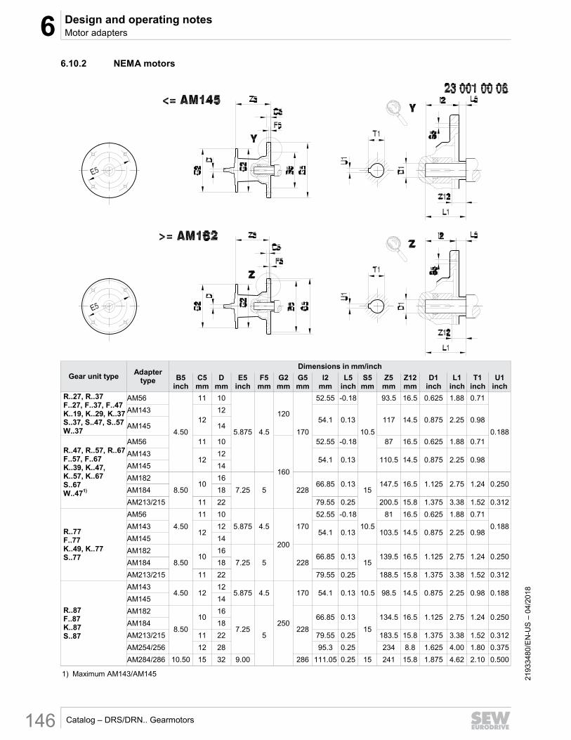
6.10.2 NEMA motors Error! B ookmark not d efined .
Gear unit type Adapter
type
Dimensions in mm/inch
B5 inch
C5 mm
D mm
E5 inch
F5 mm
G2 mm
G5 mm
l2 mm
L5 inch
S5 mm
Z5 mm
Z12 mm
D1 inch
L1 inch
T1 inch
U1 inch
R..27, R..37 F..27, F..37, F..47 K..19, K..29, K..37 S..37, S..47, S..57 W..37
AM56
4.50
11 10
5.875 4.5
120
170
52.55 -0.18
10.5
93.5 16.5 0.625 1.88 0.71
0.188
AM143 12
12 54.1 0.13 117 14.5 0.875 2.25 0.98
AM145 14
R..47, R..57, R..67 F..57, F..67 K..39, K..47, K..57, K..67 S..67 W..471)
AM56 11 10
160
52.55 -0.18 87 16.5 0.625 1.88 0.71
AM143 12
12 54.1 0.13 110.5 14.5 0.875 2.25 0.98
AM145 14
AM182
8.50 10
16
7.25 5 228 66.85 0.13
15 147.5 16.5 1.125 2.75 1.24 0.250
AM184 18
AM213/215 11 22 79.55 0.25 200.5 15.8 1.375 3.38 1.52 0.312
R..77 F..77 K..49, K..77 S..77
AM56
4.50
11 10
5.875 4.5
200
170
52.55 -0.18
10.5
81 16.5 0.625 1.88 0.71
0.188 AM143 12
12 54.1 0.13 103.5 14.5 0.875 2.25 0.98
AM145 14
AM182
8.50 10
16
7.25 5 228 66.85 0.13
15 139.5 16.5 1.125 2.75 1.24 0.250
AM184 18
AM213/215 11 22 79.55 0.25 188.5 15.8 1.375 3.38 1.52 0.312
R..87 F..87 K..87 S..87
AM143 4.50 12
12 5.875 4.5
250
170 54.1 0.13 10.5 98.5 14.5 0.875 2.25 0.98 0.188 AM145 14
AM182
8.50
10 16
7.25 5
228
66.85 0.13
15
134.5 16.5 1.125 2.75 1.24 0.250 AM184 18
AM213/215 11 22 79.55 0.25 183.5 15.8 1.375 3.38 1.52 0.312
AM254/256 12 28 95.3 0.25 234 8.8 1.625 4.00 1.80 0.375
AM284/286 10.50 15 32 9.00 286 111.05 0.25 15 241 15.8 1.875 4.62 2.10 0.500
1) Maximum AM143/AM145
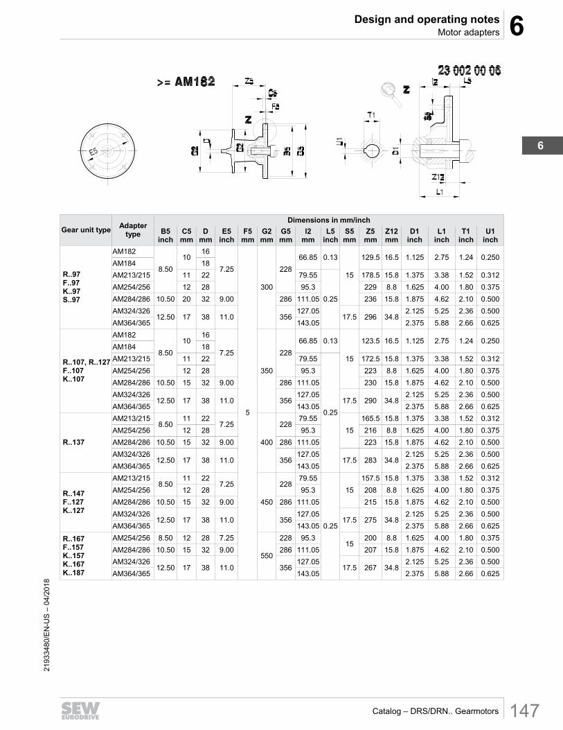
6 Design and operating notesMotor adapters
6
Catalog – DRS/DRN.. Gearmotors 147
2193
3480
/EN
-US
– 0
4/20
18
Gear unit type Adapter
type
Dimensions in mm/inch
B5 inch
C5 mm
D mm
E5 inch
F5 mm
G2 mm
G5 mm
l2 mm
L5 inch
S5 mm
Z5 mm
Z12 mm
D1 inch
L1 inch
T1 inch
U1 inch
R..97 F..97 K..97 S..97
AM182
8.50
10 16
7.25
5
300
228
66.85 0.13
15
129.5 16.5 1.125 2.75 1.24 0.250 AM184 18
AM213/215 11 22 79.55
0.25
178.5 15.8 1.375 3.38 1.52 0.312
AM254/256 12 28 95.3 229 8.8 1.625 4.00 1.80 0.375
AM284/286 10.50 20 32 9.00 286 111.05 236 15.8 1.875 4.62 2.10 0.500
AM324/326 12.50 17 38 11.0 356
127.05 17.5 296 34.8
2.125 5.25 2.36 0.500
AM364/365 143.05 2.375 5.88 2.66 0.625
R..107, R..127 F..107 K..107
AM182
8.50
10 16
7.25
350
228
66.85 0.13
15
123.5 16.5 1.125 2.75 1.24 0.250 AM184 18
AM213/215 11 22 79.55
0.25
172.5 15.8 1.375 3.38 1.52 0.312
AM254/256 12 28 95.3 223 8.8 1.625 4.00 1.80 0.375
AM284/286 10.50 15 32 9.00 286 111.05 230 15.8 1.875 4.62 2.10 0.500
AM324/326 12.50 17 38 11.0 356
127.05 17.5 290 34.8
2.125 5.25 2.36 0.500
AM364/365 143.05 2.375 5.88 2.66 0.625
R..137
AM213/215 8.50
11 22 7.25
400
228 79.55
15
165.5 15.8 1.375 3.38 1.52 0.312
AM254/256 12 28 95.3 216 8.8 1.625 4.00 1.80 0.375
AM284/286 10.50 15 32 9.00 286 111.05 223 15.8 1.875 4.62 2.10 0.500
AM324/326 12.50 17 38 11.0 356
127.05 17.5 283 34.8
2.125 5.25 2.36 0.500
AM364/365 143.05 2.375 5.88 2.66 0.625
R..147 F..127 K..127
AM213/215 8.50
11 22 7.25
450
228 79.55
0.25
15
157.5 15.8 1.375 3.38 1.52 0.312
AM254/256 12 28 95.3 208 8.8 1.625 4.00 1.80 0.375
AM284/286 10.50 15 32 9.00 286 111.05 215 15.8 1.875 4.62 2.10 0.500
AM324/326 12.50 17 38 11.0 356
127.05 17.5 275 34.8
2.125 5.25 2.36 0.500
AM364/365 143.05 2.375 5.88 2.66 0.625
R..167 F..157 K..157 K..167 K..187
AM254/256 8.50 12 28 7.25
550
228 95.3 15
200 8.8 1.625 4.00 1.80 0.375
AM284/286 10.50 15 32 9.00 286 111.05 207 15.8 1.875 4.62 2.10 0.500
AM324/326 12.50 17 38 11.0 356
127.05 17.5 267 34.8
2.125 5.25 2.36 0.500
AM364/365 143.05 2.375 5.88 2.66 0.625

6 Design and operating notes Motor adapters
Catalog – DRS/DRN.. Gearmotors 148
2193
3480
/EN
-US
– 0
4/20
18
6.10.3 Servomotors Error! B ookmark not d efined .
Gear unit type Adapter type Dimensions in mm
A5 B5 D E5 F5 G2 S5 Z5 Z121) Z122) D1 L1 T11) U11)
R..27, R..37 F..27, F..37, F..47 K..19, K..29, K..37 S..37, S..47, S..57 W..37
AQ..80/1
82 60 10
12 75
3
120
M5 104.5 5.5 5.5
11 23 12.8 4
AQ..80/2
14 30 16.3
5 AQ..80/3 50 95
M6 AQ..100/1
100
80
10 12 14 16
100
4
129.5 - - 5 AQ..100/2 95 115 M8
AQ..100/3 80 100 M6 143.5 2 14
19 40 21.8 6 AQ..100/4
95 115
M8 AQ..115/1
115 130 152.5 11 23
AQ..115/2 110
AQ..115/3 16 16 24 50 27.3 8
R..47, R..57, R..67 F..57, F..67 K..39, K..473) , K..57, K..67 S..67 W..47
AQ..80/1
82 60 10
12 75
3
160
M5 98 5.5 5.5
11 23 12.8 4
AQ..80/2
14 30 16.3 5 AQ..80/3 50 95
M6 AQ..100/1
100
80
10 12 14 16
100
4
122.5 - - AQ..100/2 95 115 M8
AQ..100/3 80 100 M6 136.5 2 14
19 40 21.8 6 AQ..100/4
95 115
M8 AQ..115/1
115 130 145.5 11 23
AQ..115/2
110 AQ..115/3
16 16 24 50 27.3 8 AQ..140/1
140 16 18 22
165
5
M10
175 AQ..140/2
130 AQ..140/3
188 22 22
32
60
35.5 10
AQ..140/4 28 31.3 8
AQ..160/1 162 155 190
32 35.3 10
AQ..190/1
190
130 22 28
215 M12 237.5 24 24
AQ..190/2 180
AQ..190/3 261.5 34 34 38 80 41.3
1) For designs with keyway (AQA..)
2) For designs with clamping ring hub (AQH..)
3) Not with AQ190

6 Design and operating notesMotor adapters
6
Catalog – DRS/DRN.. Gearmotors 149
2193
3480
/EN
-US
– 0
4/20
18
Gear unit type Adapter type Dimensions in mm
A5 B5 D E5 F5 G2 S5 Z5 Z121) Z122) D1 L1 T11) U11)
R..77 F..77 K..49, K..77 S..77
AQ..80/1 82
60 10 12
75 3
200
M5 92 5.5 5.5
11 23 12.8 4 AQ..80/2
14 30 16.3 5 AQ..80/3 50 95
M6 AQ..100/1
100
80
10 12 14 16
100
4
115.5 - - AQ..100/2 95 115 M8 AQ..100/3 80 100 M6
129.5 2 14 19 40 21.8 6
AQ..100/4 95
115
M8 AQ..115/1
115 130 138.5 11 23
AQ..115/2 110 AQ..115/3
16 16 24 50 27.3 8 AQ..140/1
140 16 18 22
165
5
M10
167 AQ..140/2
130 AQ..140/3 180 22 22
32
60
35.3 10 AQ..140/4 28 31.3 8 AQ..160/1 162 155 190
32 35.3
10 AQ..190/1
190 130
22 28
215 M12 225.5 24 24 35.3
AQ..190/2 180
AQ..190/3 249.5 34 34 38 80 41.3
R..87 F..87 K..87 S..87
AQ..100/1
100
80
12 14 16
100
4
250
M6 110.5 - - 14 30 16.3 5
AQ..100/2 95 115 M8 AQ..100/3 80 100 M6
124.5 2 14 19 40 21.8 6
AQ..100/4 95
115
M8 AQ..115/1
115 130 133.5 11 23
AQ..115/2 110 AQ..115/3
16 16 24 50 27.3 8 AQ..140/1
140 16 18 22
165
5
M10
162 AQ..140/2
130 AQ..140/3 175 22 22
32
60
35.3 10 AQ..140/4 28 31.3 8 AQ..160/1 162 155 190
32 35.3 10
AQ..190/1 190
130 22 28
215 M12 220.5 24 24
AQ..190/2 180
AQ..190/3 244.5 34 34 38 80 41.3
1) For designs with keyway (AQA..)
2) For designs with clamping ring hub (AQH..)

6 Design and operating notes Motor adapters
Catalog – DRS/DRN.. Gearmotors 150
2193
3480
/EN
-US
– 0
4/20
18
Gear unit type Adapter type Dimensions in mm
A5 B5 D E5 F5 G2 S5 Z5 Z121) Z122) D1 L1 T11) U11)
R..97 F..97 K..97 S..97
AQ..140/1
140
110
16 18 22
165
5
300
M10
157 16 16 24 50 27.3 8 AQ..140/2
130 AQ..140/3
170 22 22
32
60
35.3 10
AQ..140/4 28 31.3 8
AQ..160/1 162 155 190
32 35.3 10
AQ..190/1
190
130 22 28
215 M12 215.5 24 24
AQ..190/2 180
AQ..190/3 239.5 34 34 38 80 41.3
R..107 F..107 K..107
AQ..140/1
140
110
16 18 22
165
350
M10
151 16 16 24 50 27.3 8 AQ..140/2
130 AQ..140/3
164 22 22
32
60
35.3 10
AQ..140/4 28 31.3 8
AQ..160/1 162 155 190
32 35.3
10
AQ..190/1
190
130
22 28
215 M12
209.5 24 24 AQ..190/2
180 AQ..190/3 233.5 34 34 38 80 41.3
R..137
AQ..190/1 130
400 202.5 24 24 32 60 35.3
AQ..190/2 180
AQ..190/3 226.5 34 34 38 80 41.3
R..147 F..127 K..127
AQ..190/1 130
450 194.5 24 24 32 60 35.3
AQ..190/2 180
AQ..190/3 218.5 34 34 38 80 41.3
1) For designs with keyway (AQA..)
2) For designs with clamping ring hub (AQH..)

6 Design and operating notesGear unit mounting
6
Catalog – DRS/DRN.. Gearmotors 151
2193
3480
/EN
-US
– 0
4/20
18
6.11 Gear unit mounting
6.11.1 Foot or flange mounting
INFORMATION
Alignment is critical when installing gear units with a flange or with feet. Installation recommendations are available online within the Technical Notes section at:
→ www.seweurodrive.com
For gear units with a flange, review Technical Note GM-020. For gear units with hollow shaft and feet, review Technical Note GM-019.
Bolt strength: Error! B ookmark not d efined .Error! Boo kmark not defin ed .
Always install gearmotors using screws of strength class 8.8.
Gearmotors in flange-mounted design and in foot-/flange-mounted design listed in the following table are an exception. Always use screws of strength class 10.9 for these gearmotors. In addition, use suitable washers.
Gear unit Flange Ø in mm Strength class of the
screws
RF37/R37F 120
10.9
RF47/R47F 140
RF57/R57F 160
FF/FAF77/KF/KAF77 250
RF147 450
RF167 550
RZ37 – RZ87 60ZR – 130ZR
All other units 8.8

6 Design and operating notes Gear unit mounting
Catalog – DRS/DRN.. Gearmotors 152
2193
3480
/EN
-US
– 0
4/20
18
Lifting Eyebolts:
R07..R27 helical gear units, motors up to DRN..100 and the Spiroplan® gearmotors W..10 to W..30 are delivered without additional hardware for ease of handling. All other gear units and motors are equipped with cast-on suspension eye lugs, screw-on suspension eye lugs, or screw-on lifting eyebolts, as noted below.
.
Gear Unit Screw-on
Cast-on eyebolts lifting eyebolts eyebolts
R..37 - R..57 X
R..67 - R..107 X
RX57 - RX67 X
RX77 - RX107 X
F..27 - F..157 X
K..37 - K..157 X
K..167 - K..187 X
S..37 - S..47 X
S..57 - S..97 X
W37 - W47 X
X = Standard; blank = not available

6 Design and operating notesGear unit mounting
6
Catalog – DRS/DRN.. Gearmotors 153
2193
3480
/EN
-US
– 0
4/20
18
6.11.2 Torque arm mounting
DANGER NOTICE
If gear units with hollow shaft and feet (e.g. KA19/29B, KA127/157B or FA127/157B) are mounted via both a torque arm and feet, injury or damage could result due to binding forces!
• KA.9B/T design: Do NOT use the feet and torque arm at the same time. Mount via the torque arm only.
• K.9 or KA.9B: Mount via the feet only.
• If you have a special need for using both the feet and torque arm, contact SEW-EURODRIVE.
Part numbers
The following table lists the part numbers of available torque arms and rubber buffers.
Gear unit Size
19 29 39 49
KA, KH, KT 10684115 10684107 10682163 06442439
Gear unit Size
27 37 47 57 67 77
KA, KH, KV, KT - 6434258 6434282 6434312 6434312 6434347
SA, SH, ST - 1269941 6442374 6442404 6442439 6442463
FA, FH, FV, FT Rubber buffer (2 pieces)
0133485 0133485 0133485 0133485 0133485 0133493
Gear unit Size
87 97 107 127 157 167/187
KA, KH, KV, KT 6434371 6434401 6434436 6432948 6432956- N/A
SA, SH, ST 6442498 6442528 - - - -
FA, FH, FV, FT Rubber buffer (2 pieces)
0133493 0133507 0133507 0133515 0133477 -
Gear unit Size
10 20 30 37 47
WA, WH, WT 10610219 1680730 1680110 10611290 10611851
INFORMATION
For proper design and mounting of torque arms and torque arm brackets, please see Technical Note GM-021, available at:
→ www.seweurodrive.com

6 Design and operating notes Flange contours
Catalog – DRS/DRN.. Gearmotors 154
2193
3480
/EN
-US
– 0
4/20
18
6.12 Flange contours
6.12.1 RF.. and R..F Error! B ookmark not d efined .
18014402819653387
Check dimensions L1 and L2 for selection and installation of output elements.
Type
Dimensions in mm
A1 D D1 D2 D3 F1 I2 L L1 L2
RF R..F RF R..F
RF07, R07F 120
20
22 38 38 72
3
40 40
2 2
6 1401)
- 85 -
1601) 100 3.5 2.5 - 6.5
RF17, R17F 120
25 46 46 65
3 1
1 5
140 -
78 -
1601) 95 3.5 6
RF27, R27F 120
25
30 54 54 66
3
50 50
1 1 6 140
- 79
3 - 7 160 92 3.5
RF37, R37F 120
35
60 63 70 3 5 4
160 -
96 3.5 1 - 7.5
2001) 119
RF47, R47F 140
30 72 64 82 3
60 60 4 1 6
160 -
96
3.5 0.5 - 6.5
200 116
RF57, R57F 160
35 40 76
75 96
70 70
4 2.5 5
200 -
116 0 -
2501) 160 4 0.5 5.5
RF67, R67F 200
50 90 90 118 3.5 2 4 7
250 - 160
4
1 - 7.5
RF77, R77F 250
40 52 112 100 160
80 80 0.5 2.5
7 3001) - 210 -
RF87, R87F 300
50 62 123 122 210
100 100 0 1.5 8
350 - 226
5
1 - 9
RF97 60 72 136
236 120 120
0
9 450 320
RF107 350
70 82 157 232
140 140 11 450
186 316
RF137 90 108 180 316
170 170
10
550 416
RF147
450
110 125 210
316
210 210 550 416
RF167 120 145 290 1
660 517 6 2 11
1) The flange contour protrudes from under the base surface.

6 Design and operating notesFlange contours
6
Catalog – DRS/DRN.. Gearmotors 155
2193
3480
/EN
-US
– 0
4/20
18
6.12.2 FF.., KF.., SF.. and WF.. Error! B ookmark not d efined .
9007203564915467
Check dimensions L1 and L2 for selection and installation of output elements.
Type Dimensions in mm
A1 D D1 D2 D3 F1 I2 L L1 L2 FF27
160 25 40 66 96
3.5 50 50
3 18.5 FF37 30 70 94 2 6 FF47 200 30
40 72 115 60 60 3.5 7.5
FF57 250 35 84 155
4
70 70 4
9 FF67 250 40 50 80 80
FF77 250
50 55 82 155
100 100 5 300 205
FF87 350 60 65 115 220
5
120 120 FF97
450 70 75 112 320 140 140 8 10
FF107 90 100 159 318 170 170 16 9 FF127 550 110 118 - 420
210 210 10 -
FF157 660 120 135 190 520 6 8 14
KF19 120
20 25 -
70 2.5 40 40
- 11.5
160 100
KF29 25 30
109
3.5
50 50 6.5
200 115 KF37
160 70 94 2 6
KF39 30
39 68 96 60 60
13.5 23.5 KF47
200 40 72 115 3.5 7.5
KF49 35 49 76 115 70 70 24.5 28 KF57
250 35 40
84 155 4
70 70 4
9 KF67 40 50 80 80
KF77 250
50 55 82 155
100 100 5 300 205
KF87 350 60 65 115 220
5
120 120 KF97
450 70 75 112 320 140 140 8 10
KF107 90 100 159 318 170 170 16 9 KF127 550 110 118 - 420
210 210 10 -
KF157 660 120 135 190 520 6 8 14
SF37 120 20
25 - 68 3
40 40 6
- 160
20 - 96
3.5
5.5 SF47 25 30 70 94 50 50 2 6 SF57
200 30 40 72
115 60 60 3.5 7.5
SF67 35 45 - 70 70 8.5 - SF77 250 45 55 108 160 4 90 90 8 9 SF87 350 60 65 130 220
5 120 120 6
10 SF97 450 70 75 150 320 140 140 8.5
WF10 80
16 25 - 39 2.5
40 40 30 -
120 25 39 74 3 5 30
WF20 110
20 30
44 53 -4
40 40
27 35
120 - 45
2.5
37.5 -
WF30 48 63 18 27
160 33 42
WF37 120
- 70 -
10.5
160 25.5
WF47 30 35 92 3.5 10 60 6 -

6 Design and operating notes Flange contours
Catalog – DRS/DRN.. Gearmotors 156
2193
3480
/EN
-US
– 0
4/20
18
6.12.3 FAF.., KAF.., SAF.. and WAF.. Error! B ookmark not d efined .
18014402819885835
Check dimensions L1 and L2 for selection and installation of output elements.
Type Dimensions in mm
A1 D D1 D2 D3 F1 I2 L1 L2 FAF27
160 40 25 66 96
3.5 20 3 18.5
FAF37 45 30 62 94 24 2 30 FAF47 200 50 35 70 115 25 3.5 31.5 FAF57
250 55 40 76 155 4
23.5 4 31
FAF67 23
FAF77 250
70 50 95 155
37 5
45 300 205
FAF87 350 85 60 120 220
5
30 39 FAF97
450 95 70 135
320 41.5 5.5 51
FAF107 118 90 224 41 16 52 FAF127 550 135 100 185 420 51 6 63 FAF157 660 155 120 200 520 6 60 10 74
KAF19 120
30 20 60 70
2.5 25 9 25.5 160 100
KAF29 160
40 25 / 30 - 105
3.5
33.5 - 6.5 200 - 118
KAF39 160 50 30 / 35 68 96 24.5 10 27 KAF37 160 45 30 62 94 24 2 30 KAF47 200 50 35 70 115 25 3.5 8.5 KAF49 200 55 35 / 40 76 115 32.5 16 34.5 KAF57
250 55 40 76 155 4
23.5 4 31
KAF67 23
KAF77 250
70 50 95 155
37 5
45 300 205
KAF87 350 85 60 120 220
5
30 39 KAF97
450 95 70 135
320 41.5 5.5 51
KAF107 118 90 224 41 16 52 KAF127 550 135 100 185 420 51 6 63 KAF157 660 155 120 200 520 6 60 10 74
SAF37 120
35 20 - 68 3
15 6
- 160
96
3.5
5.5 SAF47 45 30 / 25 62 94 24 2 30 SAF57
200 50 35 / 30 70
115 25 3.5 31.5
SAF67 65 45 / 40 91 42.5 4 48.5 SAF77 250 80 60 / 50 112 164 4 45.5 5 53.5 SAF87 350 95 70 / 60 131 220 5 52.5 6 62.5 SAF97 450 120 90 / 70 160 320 5 60 6.5 69
WAF10 80
25 16 - 39 2.5
23 30 -
120 39 74 3 5 30
WAF20 110
30 18 / 20
44 53 -4 30
27 35
120 - 45
2.5
37.5 -
WAF30 20 48 63 19.5 18 27
160 63 34.5 33 42
WAF37 120
35 20 / 25 54 70 19.5 10.5 27
160 34.5 25.5 42
WAF47 45 25 / 30 72 92 3.5 10 6 45

6 Design and operating notesOil aging sensor
6
Catalog – DRS/DRN.. Gearmotors 157
2193
3480
/EN
-US
– 0
4/20
18
6.13 Oil aging sensor Error! B ookmark not d efined .Error! Boo kmark not defin ed .
6.13.1 DUO10A technical data
Error! B ookmark not d efined .
DUO10A Technical data
Preset oil grades
OIL1 CLP mineral oil. Tmax = 100 °C
Bio oil Tmax = 100 °C
OIL2 CLP HC synthetic oil: Tmax = 130 °C
CLP PAO oil Tmax = 130 °C
OIL3 Polyglycol CLP PG Tmax = 130 °C
OIL4 Food grade oil Tmax = 100 °C
Switch outputs
1: Early warning (time to next oil change can be set to between 2 and 100 days)
2: Main alarm (time to oil change 0 days)
3: Maximum temperature exceeded Tmax
4: DUO10A is ready for operation
Permitted oil temperature -40 °C – +130 °C
Permitted temperature sensor
PT1000
EMC IEC1000-4-2/3/4/6
Ambient temperature -25 °C – +70 °C
Operating voltage DC 18 – 28 V
Current consumption for DC 24 V
< 90 mA
Protection class III
Degree of protection IP67 (optionally IP69K)
Housing materials Evaluation unit: V2A, EPDM/X, PBT, FPM
Temperature sensor: V4A
Electrical connection Evaluation unit: M12 plug connector
PT1000 temperature sensor: M12 plug connector

6 Design and operating notes Oil aging sensor
Catalog – DRS/DRN.. Gearmotors 158
2193
3480
/EN
-US
– 0
4/20
18
6.13.2 Part numbers
Designation Description Part number
DUO10A
Evaluation unit (basic unit) 13438751
DUO10A-PUR-M12-5m 5 m PUR cable with 1 connector 13438778
DUO10A-PVC-M12-5m 5 m PVC cable with 1 connector 13438786
DUO10A Angle bracket 13438808
DUO10A D = 34 Mounting clamp 13438794
W4843 PT1000
PT1000 temperature sensor 13438816
W4843_4x0,34-2m-PUR 2 m PUR cable for PT10001) 13438824
W4843_4x0,34-2m-PVC 2 m PVC cable for PT10002) 13438832
DUO10A
Protection cap (for aseptic design, IP69K)
13439022
1) PUR cables are particularly suited for use in oil-contaminated environments.
2) PVC cables are particularly suited for use in moist environments.

6 Design and operating notesOil aging sensor
6
Catalog – DRS/DRN.. Gearmotors 159
2193
3480
/EN
-US
– 0
4/20
18
6.13.3 Mounting to gear units (R, F, K,S)
Adapter for mounting the PT1000 temperature sensor in screw plug holes:
Complete adapter for PT1000 sensor Part number
M10 × 1 13439030
M12 × 1.5 13439049
M22 × 1.5 13439057
M33 × 2 13439065
M42 × 2 13439073
Mounting base for installing the diagnostic unit at the gear unit with an angle bracket:
Mounting base with sealing ring Part number
M10 × 1 13434411
M12 × 1.5 13438271
M22 × 1.5 13438298
M33 × 2 13438301
M42 × 2 13438328