6 belt and 12 disc abrasive finishing machine - service parts · prevent tripping or placing arms,...
TRANSCRIPT

INS
TRU
CTIO
NM
AN
UA
L6" Belt and 12" Disc
Abrasive Finishing Machine(Model 31-735)
PART NO. 913180 - 10-13-03Copyright © 2003 Delta Machinery
To learn more about DELTA MACHINERY visit our website at: www.deltamachinery.com.For Parts, Service, Warranty or other Assistance,
please call 1-800-223-7278 (In Canada call 1-800-463-3582).

2
Indicates an imminently hazardous situation which, if not avoided, will result in death or serious injury.
Indicates a potentially hazardous situation which, if not avoided, could result in death or serious injury.
Indicates a potentially hazardous situation which, if not avoided, may result in minor or moderate injury.
Used without the safety alert symbol indicates potentially hazardous situation which, if not avoided, mayresult in property damage.
This manual contains information that is important for you to know and understand. This information relates to protect-ing YOUR SAFETY and PREVENTING EQUIPMENT PROBLEMS. To help you recognize this information, we use thesymbols to the right. Please read the manual and pay attention to these sections.
SAFETY GUIDELINES - DEFINITIONS
SOME DUST CREATED BY POWER SANDING, SAWING, GRINDING, DRILLING, AND OTHERCONSTRUCTION ACTIVITIES contains chemicals known to cause cancer, birth defects or other reproductive harm.Some examples of these chemicals are:· lead from lead-based paints,· crystalline silica from bricks and cement and other masonry products, and· arsenic and chromium from chemically-treated lumber. Your risk from these exposures varies, depending on how often you do this type of work. To reduce your exposure tothese chemicals: work in a well ventilated area, and work with approved safety equipment, always wear MSHA/NIOSHapproved, properly fitting face mask or respirator when using such tools.
GENERAL SAFETY RULES
READ AND UNDERSTAND ALL WARNINGS AND OPERATING INSTRUCTIONS BEFOREUSING THIS EQUIPMENT. Failure to follow all instructions listed below, may result in electric shock,fire, and/or serious personal injury or property damage.
IMPORTANT SAFETY INSTRUCTIONS
Woodworking can be dangerous if safe and proper operating procedures are not followed. As with all machinery, thereare certain hazards involved with the operation of the product. Using the machine with respect and caution willconsiderably lessen the possibility of personal injury. However, if normal safety precautions are overlooked or ignored,personal injury to the operator may result. Safety equipment such as guards, push sticks, hold-downs, featherboards,goggles, dust masks and hearing protection can reduce your potential for injury. But even the best guard won’t makeup for poor judgment, carelessness or inattention. Always use common sense and exercise caution in the workshop.If a procedure feels dangerous, don’t try it. Figure out an alternative procedure that feels safer. REMEMBER: Yourpersonal safety is your responsibility. For additional information please visit our website www.deltamachinery.com.
This machine was designed for certain applications only. Delta Machinery strongly recommends that thismachine not be modified and/or used for any application other than that for which it was designed. If you have anyquestions relative to a particular application, DO NOT use the machine until you have first contacted Delta to determineif it can or should be performed on the product.
Technical Service ManagerDelta Machinery4825 Highway 45 NorthJackson, TN 38305
(IN CANADA: 505 SOUTHGATE DRIVE, GUELPH, ONTARIO N1H 6M7)

3
FAILURE TO FOLLOW THESE RULES MAY RESULT IN SERIOUS PERSONAL INJURY.
1. FOR YOUR OWN SAFETY, READ THE INSTRUC-TION MANUAL BEFORE OPERATING THEMACHINE. Learning the machine’s application,limitations, and specific hazards will greatlyminimize the possibility of accidents and injury.
2. USE CERTIFIED SAFETY EQUIPMENT. Eyeprotection should comply with ANSI Z87.1standards, hearing protection should comply withANSI S3.19 standards, and dust mask protectionshould comply with MSHA/NIOSH certifiedrespirator standards. Splinters, air-borne debris,and dust can cause irritation, injury, and/or illness.
3. DRESS PROPERLY. Do not wear tie, gloves, orloose clothing. Remove watch, rings, and otherjewelry. Roll up your sleeves. Clothing or jewelrycaught in moving parts can cause injury.
4. DO NOT USE THE MACHINE IN A DANGEROUSENVIRONMENT. The use of power tools in dampor wet locations or in rain can cause shock orelectrocution. Keep your work area well-lit toprevent tripping or placing arms, hands, andfingers in danger.
5. MAINTAIN ALL TOOLS AND MACHINES IN PEAKCONDITION. Keep tools sharp and clean for best andsafest performance. Follow instructions for lubricatingand changing accessories. Poorly maintained tools andmachines can further damage the tool or machine and/orcause injury.
6. CHECK FOR DAMAGED PARTS. Before using themachine, check for any damaged parts. Check foralignment of moving parts, binding of movingparts, breakage of parts, and any other conditionsthat may affect its operation. A guard or any otherpart that is damaged should be properly repairedor replaced. Damaged parts can cause furtherdamage to the machine and/or injury.
7. KEEP THE WORK AREA CLEAN. Cluttered areas andbenches invite accidents.
8. KEEP CHILDREN AND VISITORS AWAY. Your shop isa potentially dangerous environment. Children and visitorscan be injured.
9. REDUCE THE RISK OF UNINTENTIONAL STARTING.Make sure that the switch is in the “OFF” positionbefore plugging in the power cord. In the event ofa power failure, move the switch to the “OFF”position. An accidental start-up can cause injury.
10. USE THE GUARDS. Check to see that all guardsare in place, secured, and working correctly toprevent injury.
11. REMOVE ADJUSTING KEYS AND WRENCHESBEFORE STARTING THE MACHINE. Tools, scrappieces, and other debris can be thrown at highspeed, causing injury.
12. USE THE RIGHT MACHINE. Don’t force amachine or an attachment to do a job for which itwas not designed. Damage to the machine and/orinjury may result.
13. USE RECOMMENDED ACCESSORIES. The use
of accessories and attachments not recom-mended by Delta may cause damage to themachine or injury to the user.
14. USE THE PROPER EXTENSION CORD. Makesure your extension cord is in good condition.When using an extension cord, be sure to use oneheavy enough to carry the current your product willdraw. An undersized cord will cause a drop in linevoltage, resulting in loss of power and overheating.See the Extension Cord Chart for the correct sizedepending on the cord length and nameplateampere rating. If in doubt, use the next heaviergauge. The smaller the gauge number, the heavierthe cord.
15. SECURE THE WORKPIECE. Use clamps or a vise tohold the workpiece when practical. Loss of controlof a workpiece can cause injury.
16. FEED THE WORKPIECE AGAINST THE DIRECTIONOF THE ROTATION OF THE BLADE, CUTTER, ORABRASIVE SURFACE. Feeding it from the otherdirection will cause the workpiece to be thrown outat high speed.
17. DON’T FORCE THE WORKPIECE ON THEMACHINE. Damage to the machine and/or injurymay result.
18. DON’T OVERREACH. Loss of balance can makeyou fall into a working machine, causing injury.
19. NEVER STAND ON THE MACHINE. Injury could occur ifthe tool tips, or if you accidentally contact the cutting tool.
20. NEVER LEAVE THE MACHINE RUNNING UNATTEN-DED. TURN THE POWER OFF. Don’t leave the machineuntil it comes to a complete stop. A child or visitor couldbe injured.
21. TURN THE MACHINE “OFF”, AND DISCONNECT THEMACHINE FROM THE POWER SOURCE beforeinstalling or removing accessories, before adjustingor changing set-ups, or when making repairs. Anaccidental start-up can cause injury.
22. MAKE YOUR WORKSHOP CHILDPROOF WITHPADLOCKS, MASTER SWITCHES, OR BYREMOVING STARTER KEYS. The accidentalstart-up of a machine by a child or visitor couldcause injury.
23. STAY ALERT, WATCH WHAT YOU ARE DOING,AND USE COMMON SENSE. DO NOT USE THEMACHINE WHEN YOU ARE TIRED OR UNDERTHE INFLUENCE OF DRUGS, ALCOHOL, ORMEDICATION. A moment of inattention whileoperating power tools may result in injury.
24. THE DUST GENERATED by certain woods andwood products can be injurious to your health.Always operate machinery in well-ventilated areas,and provide for proper dust removal. Use wooddust collection systems whenever possible.

4
FAILURE TO FOLLOW THESE RULES MAY RESULT IN SERIOUS PERSONAL INJURY.
SAVE THESE INSTRUCTIONS. Refer to them often and use them to instruct others.
ADDITIONAL SAFETY RULESFOR ABRASIVE FINISHING MACHINES
1. DO NOT OPERATE THIS MACHINE until it iscompletely assembled and installed according tothe instructions. A machine incorrectly assembledcan cause serious injury.
2. OBTAIN ADVICE from your supervisor, instructor, oranother qualified person if you are not thoroughlyfamiliar with the operation of this machine.Knowledge is safety.
3. FOLLOW ALL WIRING CODES and recommendedelectrical connections to prevent shock or electrocu-tion.
4. NEVER TURN THE MACHINE “ON” beforeclearing the table/work area of all objects (tools,scraps of wood, etc.). Flying debris is dangerous.
5. NEVER TURN THE MACHINE “ON” with the work-piece contacting the abrasive surface. Kickback canoccur.
6. THIS MACHINE CAN BE USED FORPROCESSING WOOD OR METAL PRODUCTS:However, combining both wood dust and metalfilings can create a fire hazard. In additioncombining aluminum dust with metal dust cancreate a fire hazard. Before processing differenttypes of materials, such as wood, steel, andaluminum, clean machine and dust collector toavoid a fire hazard. DO NOT sand or polishmagnesium. It could catch on fire.
7. COVER THE POWER TAKE-OFF SHAFT when notusing accessories. Unguarded rotating shafts cancreate an entanglement hazard which can result ininjury.
8. USE A DUST COLLECTION SYSTEM. Some typesof materials are known to cause disease or otherhealth problems.
9. CLEAN THE MACHINE and dust collector thoroughlywhen processing different types of workpieces(wood, steel, or aluminum). Combining wood andmetal dust can create an explosion or fire hazard.DO NOT SAND OR POLISH MAGNESIUM. Fire willresult.
10. PREVENT THE WORKPIECE from contacting thesanding belt before starting the tool. Loss of controlof the workpiece is dangerous.
11. AVOID AWKWARD OPERATIONS AND HANDPOSITIONS. A sudden slip could cause a hand tomove into the abrasive disc or belt.
12. MAINTAIN A MAXIMUM CLEARANCE OF 1/16" be-tween the table and the abrasive disc. Theworkpiece could be drawn into the space betweenthe abrasive disc and the table.
13. SUPPORT THE WORKPIECE firmly with a mitergauge, backstop, or work table when sanding with abelt. Hold the workpiece firmly. Loss of control of theworkpiece can result in injury.
14. AVOID KICKBACK by sanding in accordance withthe directional arrows. Feed the workpiece againstthe downward rotation side of the disc or theforward rotation of the belt. Loss of control of theworkpiece can result in injury.
15. DO NOT SAND very small or very thin workpiecesthat cannot be safely controlled. Loss of control ofthe workpiece can result in injury.
16. PROPERLY SUPPORT LONG OR WIDE WORK-PIECES. Loss of control of the workpiece is dan-gerous.
17. NEVER PERFORM LAYOUT, ASSEMBLY, OR SET-UPWORK on the table/work area when the machine isrunning. A sudden slip could cause a hand to moveinto the abrasive surface. Severe injury can result.
18. TURN THE MACHINE “OFF”, disconnect themachine from the power source, and clean thetable/work area before leaving the machine. LOCKTHE SWITCH IN THE “OFF” POSITION to preventunauthorized use. Someone else might accidentallystart the machine and cause injury to themselves.
19. DO NOT insert fingers or foreign objects into thedust intake port. Keep hair, loose clothing, fingers,and all body parts away from openings and movingparts of the dust collector.
20. DO NOT use with any opening blocked; keepopenings free of dust, lint, hair, and anything thatmay reduce air flow.
21. NEVER operate the dust collector without the dustcollection bag in place and properly secured.
22. ALWAYS use intake caps to cover unused dustports when the dust collector is not in use.
23. PERIODICALLY INSPECT dust bag for any cuts,rips or tears. NEVER operate the dust collector witha damaged bag or vacuum hose.
24. ADDITIONAL INFORMATION regarding the safeand proper operation of power tools (i.e. a safetyvideo) is available from the Power Tool Institute,1300 Sumner Avenue, Cleveland, OH 44115-2851(www.powertoolinstitute.com). Information is alsoavailable from the National Safety Council, 1121Spring Lake Drive, Itasca, IL 60143-3201. Pleaserefer to the American National Standards InstituteANSI 01.1 Safety Requirements for WoodworkingMachines and the U.S. Department of Labor OSHA1910.213 Regulations.

5
A separate electrical circuit should be used for your machines. This circuit should not be less than #12 wire and shouldbe protected with a 20 Amp time lag fuse. If an extension cord is used, use only 3-wire extension cords which have 3-prong grounding type plugs and matching receptacle which will accept the machine’s plug. Before connecting themachine to the power line, make sure the switch is in the “OFF” position and be sure that the electric current is of thesame characteristics as indicated on the machine. All line connections should make good contact. Running on lowvoltage will damage the machine.
DO NOT EXPOSE THE MACHINE TO RAIN OR OPERATE THE MACHINE IN DAMP LOCATIONS.
POWER CONNECTIONS
MOTOR SPECIFICATIONSYour machine is wired for 240, or 200/460 volt, 60 HZ alternating current. Before connecting the machine to thepower source, make sure the switch is in the “OFF” position.
GROUNDING INSTRUCTIONSTHIS MACHINE MUST BE GROUNDED WHILE IN USE TO PROTECT THE OPERATOR FROMELECTRIC SHOCK.
1. All grounded, cord-connected machines: In the event of a malfunction or breakdown, groundingprovides a path of least resistance for electric current toreduce the risk of electric shock. This machine isequipped with an electric cord having an equipment-grounding conductor and a grounding plug. The plugmust be plugged into a matching outlet that is properlyinstalled and grounded in accordance with all local codesand ordinances.Do not modify the plug provided - if it will not fit the outlet,have the proper outlet installed by a qualified electrician.Improper connection of the equipment-groundingconductor can result in risk of electric shock. Theconductor with insulation having an outer surface that isgreen with or without yellow stripes is the equipment-grounding conductor. If repair or replacement of theelectric cord or plug is necessary, do not connect theequipment-grounding conductor to a live terminal.Check with a qualified electrician or service personnel ifthe grounding instruct ions are not complete lyunderstood, or if in doubt as to whether the machine isproperly grounded.Use only 3-wire extension cords that have 3-pronggrounding type plugs and matching 3-conductorreceptacles that accept the machine’s plug, as shown inFig. A.Repair or replace damaged or worn cord immediately.
2. Grounded, cord-connected machines intended for useon a supply circuit having a nominal rating between 150- 250 volts, inclusive:
If the machine is intended for use on a circuit that has anoutlet that looks like the one illustrated in Fig. C, themachine will have a grounding plug that looks like theplug illustrated in Fig. C. Make sure the machine isconnected to an outlet having the same configuration asthe plug. No adapter is available or should be used withthis machine. If the machine must be re-connected foruse on a different type of electric circuit, the re-connection should be made by qualified servicepersonnel; and after re-connection, the machine shouldcomply with all local codes and ordinances.
IN ALL CASES, MAKE CERTAIN THER E C E P TA C L E I N Q U E S T I O N I S P R O P E R LYGROUNDED. IF YOU ARE NOT SURE HAVE AQUALIFIED ELECTRICIAN CHECK THE RECEPTACLE.3. Permanently connected machines:If the machine is intended to be permanently connected,the machine should be connected to a grounded metalpermanent wiring system, or to a system having anequipment-grounding conductor.
Fig. A
GROUNDED OUTLET BOXCURRENTCARRYING
PRONGS
GROUNDING BLADEIS LONGEST OF THE 3 BLADES

6
Use proper extension cords. Make sure your extension cord is in good condition and is a 3-wireextension cord which has a 3-prong grounding type plug and matching receptacle which will accept the machine’splug. When using an extension cord, be sure to use one heavy enough to carry the current of the machine. Anundersized cord will cause a drop in line voltage, resulting in loss of power and overheating. Fig. D, shows the correctgauge to use depending on the cord length. If in doubt, use the next heavier gauge. The smaller the gauge number,the heavier the cord.
EXTENSION CORDS
Fig. D
MINIMUM GAUGE EXTENSION CORDRECOMMENDED SIZES FOR USE WITH STATIONARY ELECTRIC MACHINES
Ampere Total Length Gauge ofRating Volts of Cord in Feet Extension Cord
0-6 240 up to 50 18 AWG0-6 240 50-100 16 AWG0-6 240 100-200 16 AWG0-6 240 200-300 14 AWG
6-10 240 up to 50 18 AWG6-10 240 50-100 16 AWG6-10 240 100-200 14 AWG6-10 240 200-300 12 AWG
10-12 240 up to 50 16 AWG10-12 240 50-100 16 AWG10-12 240 100-200 14 AWG10-12 240 200-300 12 AWG
12-16 240 up to 50 14 AWG12-16 240 50-100 12 AWG12-16 240 GREATER THAN 100 FEET NOT RECOMMENDED
THREE PHASE OPERATIONIf the motor on your machine is wired for 200V, 230V, or 460V, three phase, the necessary wiring from the starter to thepower should be completed by a qualified electrician.
FOREWORDDelta Model 31-735 is an abrasive finishing machine. The Delta Model 31-735 includes two tilting tables, 4½" arborpulley, V-belt, 100-grit aluminum oxide belt and 80-grit aluminum oxide disc.
FUNCTIONAL DESCRIPTION
UNPACKING AND CLEANINGCarefully unpack the machine and all loose items from the shipping container. Remove the protective coating from allunpainted surfaces. This coating may be removed with a soft cloth moistened with kerosene (do not use acetone, gasoline orlacquer thinner for this purpose). After cleaning, cover the unpainted surfaces with a good quality household floor paste wax.

7
CARTON CONTENTS
1
2
34
6
5
7
8
9
10
11
1. Cabinet
2. Dust Baffle
3. Bag Hanger
4. Dust Chute
5. Dust Bag
6. Hose (2)
7. Hose Clamp (5)
8. Belt / Disc Sander
9. Belt Sanding Table
10. Abrasive Disc
11. Disc Sanding Table
12. Caster
13. Foot Lever
14. Bracket
15. Pivot Bracket
16. 1/2x4" Pin
17. 1/2" Flat Washer (2)
18. Retaining Ring (2)
19. 5/16-18x4" Hex Head Screw
20. 5/16-18 Lock Nut
21. 3/8-16x1" Carriage Head Bolt (3)
22. 3/8" Flat Washer (3)
23. 3/8-16 Hex Nut (3)
24. 1/4-20x5/8" Flat Head Screw (4)
25. 1/4" Flat Washer (4)
26. 1/4-20 Hex Nut (4)
27. 5/16-18x1/2" Hex Head Screw (4)
28. 5/16" Lockwasher (4)
29. #10-32x3/4" Button Head Screw (4)
30. #10 Flat Washer (4)
31. M4-0.7x12mm Sheet Metal Screw (4)
32. 3/8-16 Lock Nut
33. 1-3/16" Spring
34. Ratchet Lever
35. 3/8-16x3½" Stud
36. 3/8-16 Hex Nut
37. 3/8 Flat Washer
38. Disc Table Lock Handle (2)
39. 1/2" Spring (2)
40. 7/16-18x3" Stud (2)
41. 7/16" Flat Washer (2)
42. Disc Table Clamp (2)
43. 1/4-20x1/4" Round Head Screw
44. Pointer
45. Circle Sanding Stop Block
46. Circle Sanding Guide Pin
Fig. 1
12 13
14 15
1617
18
19 2021 22 23
24 2627 28
29 3031
32
33 34
35 36 37
38
39
40 41
4243 44
45 4625

8
ASSEMBLYFOR YOUR OWN SAFETY, DO NOT CONNECT THE MACHINE TO THE POWER SOURCE UNTIL
THE MACHINE IS COMPLETELY ASSEMBLED AND YOU READ AND UNDERSTAND THE ENTIREINSTRUCTION MANUAL.
CASTER ASSEMBLY / FOOT LEVER1. DISCONNECT MACHINE FROM
POWER SOURCE.
2. Place the motor cabinet on its side.
3. Align the three holes in the bracket (B) Fig. 2A, withthe three holes in the inside of the base (C).
4. Align the three holes in the pivot bracket (D) Fig. 2B,with the three holes in the outside of the base (C).
5. Insert a 3/8-16x1" carriage head bolt through thehole in bracket (B) Fig. 2A, the base (C), and the pivotbracket (D) Fig. 2B. Place a 3/8" flat washer on thescrew, and thread a 3/8-16 hex nut on the screw andtighten securely. Repeat this process for the tworemaining holes.
6. Align the two holes in the caster assembly (E) Fig.2C, with the two holes (F) in the pivot bracket.
Fig. 2A
Fig. 2B
Fig. 2C
B
C
D
C
E
F

9
Fig. 2E
Fig. 2D
Fig. 2F
7. Insert a 5/16-18x4" hex head screw (G) Fig. 2D,through the hole (F) Fig. 2C, in the pivot bracket, the twoholes (E) in the caster assembly and the other hole (F) inthe pivot bracket. Thread a 5/16-18 lock nut onto thescrew and tighten securely.
8. Align the two holes (H) Fig 2E, in the foot lever, withthe two holes (J) in the pivot bracket.
9. Assemble foot lever (N) Fig. 2F, to pivot bracket (O),using 1/2"x4" pin (M), two 1/2" flat washers (K), and tworetaining rings (P) as shown in Fig. 2F.
10. Stand the motor cabinet up on its base.
G
H
J
NOM
K
P
P

10
DUST BAFFLE1. DISCONNECT MACHINE FROM
POWER SOURCE.
2. Remove the two screws (A) Fig. 3, and loosen thetwo screws (B).
3. Remove the back cover of the cabinet (C) Fig. 3.
Fig. 3
Fig. 4
Fig. 5
Fig. 6
4. Loosen the four nuts (D) Fig. 4, and lower the motor.
5. Insert the dust baffle (F) Fig. 5, through the front ofthe cabinet.
6. Align the four slots in the dust baffle with the fourholes (G) Fig. 6, in the top of the cabinet.
7. Insert a 1/4-20x5/8" flat head screw through hole (G)Fig. 6 in the top of the cabinet and the dust baffle. Placea 1/4" flat washer onto the screw, thread a 1/4-20 hexnut onto the screw, from the inside of the cabinet andtighten securely.
8. Repeat this process for the three remaining holes inthe top of the cabinet and the dust baffle.
A
B
C
D
F
GG
CABINETTOP

11
BELT / DISC SANDER TO CABINET
THE BELT / DISC SANDER IS HEAVY,USE TWO OR MORE PEOPLE WHENPLACING THE BELT / DISC SANDERON TOP OF THE CABINET.
1. DISCONNECT MACHINE FROM POWER SOURCE.
2. Place the Belt/Disc sander on top of the cabinet.
NOTE: MAKE SURE THE DRIVE BELT ON THEDISC/BELT SANDER IS INSERTED THROUGH THEHOLE (A) FIG. 7.
3. Place a 5/16" lock washer onto a 5/16-18x½" hexhead screw. Insert the screw, from the inside of thecabinet, through the hole (B) Fig. 7, and thread into theBelt/Disc sander. Tighten the screw securely.
4. Repeat this process for the three remaining holes (B)Fig. 7, in the cabinet and the Belt/Disc sander.
5. Place a #10 washer onto a #10-32x3/4" button headscrew. Insert the screw, from the inside of the cabinet,through the slot (C) Fig. 7, in the dust baffle, and cabinetand thread the screw into the Belt/Disc sander. Tightenthe screw securely.
6. Repeat this process for the three remaining slots inthe dust baffle, cabinet, and the Belt/Disc sander.
7. Fig. 8 shows the Belt/Disc sander attached to thecabinet.
Fig. 7
Fig. 8
DUST COLLECTOR INTAKE HOSE1. DISCONNECT MACHINE FROM
POWER SOURCE.2. Place a hose clamp (A) Fig. 9, on each end of hose(B).
3. Slide one end of hose (B) Fig. 10, over the hose port(C) on the dust baffle, from the inside of the cabinet.Tighten the hose clamp around the hose port on thedust baffle.
4. Slide the other end of the hose over the fan intakeport (F) Fig. 11, from the inside of the cabinet. Tightenthe hose clamp around the fan intake port.
Fig. 10 Fig. 11
Fig. 9
B B
C C
A A
B
C
B
F
A

12
BELT TO MOTOR1. DISCONNECT MACHINE FROM
POWER SOURCE.
2. Remove the two screws (A) Fig. 12, on top of thedisc sander and remove plate (B).
Fig. 12
Fig. 13
Fig. 15
Fig. 14
3. Make sure that the belt (C) Fig. 13, is in the grooveof the pulley (D) on the disc sander.
4. Lift up on motor (F) Fig. 14, and place belt (C) on themotor pulley (G).
5. Slowly release motor (F) Fig. 14, to apply pressure tobelt (C).
6. Make sure that the motor is level and tighten hexnuts (H) Fig. 15, to hold the motor in place.
A
B
C
D
F
C
G
H

13
DUST CHUTE1. DISCONNECT MACHINE FROM
POWER SOURCE.
2. Insert the dust chute (A) Fig. 16, through the insidehole of the cabinet back panel (B) that was removed inSTEP 3 of the section “DUST BAFFLE”.
3. Align the four holes in the dust chute (A) Fig. 17, withthe four holes in the back panel (B). Insert a M4-0.7x12mm sheet metal screw (C) Fig. 17, through theback panel (B), and thread the screw into the dust chuteand tighten securely.
4. Repeat this process for the three remaining holes inthe back panel and dust chute.
Fig. 16
Fig. 17
2. Place a hose clamp (A) Fig. 18, on each end of hose(B).
3. Slide one end of hose (B) Fig. 19, over the dustcollector outtake port (C). Tighten the hose clamp (A)around the dust collector outtake port (C).
4. Slide the other end of the hose (B) Fig. 20, over thedust chute (D), on the inside of the back panel of thecabinet. Tighten the hose clamp (A) around the dustchute (D).
5. Replace the back panel of cabinet that was removedin STEP 3 of the section “DUST BAFFLE”.
Fig. 20
Fig. 18
Fig. 19
1. DISCONNECT MACHINE FROM POWER SOURCE.
DUST COLLECTOROUTTAKE HOSE
A
B
B
C
A
C
A A
B
B
C A B
D
A

14
BELT SANDER TABLE1. DISCONNECT MACHINE FROM
POWER SOURCE.
2. Thread a 3/8-16 lock nut (A) Fig. 21, onto a 3/8-16x3½" stud (B).NOTE: THREAD LOCK NUT FAR ENOUGH SO THATTHE NUT (A) FIG. 12 IS FLUSH OR SLIGHTLY BELOWTHE THREADS ON THE STUD.
3. Place a 1-3/16" spring (C) Fig. 21, onto stud (B).
4. Insert sanding ratchet lever (D) Fig. 21, onto stud (B).
5. Thread a 3/8-16 hex nut (E) Fig. 21, onto stud (B).
6. Place a 3/8" flat washer (F) Fig. 21, onto stud (B).
Fig. 21
7. Loosen ratchet lever (H) Fig. 22, and raise the beltsander so that it is in the horizontal position as shownand tighten lock knob (H).
Fig. 22
8. Align the sanding table guide (J) Fig. 23, with cutout(K) Fig. 23, on the side of the sanding belt frame.
Fig. 23
Fig. 24
9. Thread the sanding ratchet lever / stud assembly (L)Fig. 24, through the sanding table slot (N) Figs. 23 and24, and into the tapped hole (M) Fig. 23, in the side ofthe sanding frame.NOTE: THREAD THE SANDING TABLE RATCHETLEVER / STUD ASSEMBLY APPROXIMATELY 1/2"INTO THE SANDING TABLE FRAME.
10. Use the sanding table ratchet lever to thread the hexnut (E) Fig 21, against the sanding table, to hold thesanding table in place.NOTE: THE RATCHET LEVER (A) FIG. 24 CAN BEREPOSITIONED BY PULLING OUT ON THE HANDLEAND REPOSITIONING IT ON THE NUT LOCATEDUNDERNEATH THE HUB OF THE RATCHET LEVER.
A B
C
D
E
F
H
J
K
M
N
LN
K
THE EDGE OF THE TABLE MUST BEPOSITIONED A MAXIMUM OF 1/16INCH AWAY FROM THE SANDING BELTTO AVOID TRAPPING THE WORK ORFINGERS BETWEEN THE TABLE ANDSANDING BELT.

15
DISC SANDER TABLE AND POINTER1. DISCONNECT MACHINE FROM
POWER SOURCE.
2. Thread the 7/16x3" disc sanding table studs (A) Fig.25, into the side of the disc sander.
Fig. 25
3. Place the disc sander table clamp (B) onto stud (A)as shown in Fig. 26. Repeat this process for theremaining stud (A) Fig. 25, on the other side of the discsander.
Fig. 26
Fig. 27
4. Align the table lock rail (C) Fig. 27, on the discsander table, with the grooves in the table clamps (B).
Fig. 28
5. Place a 7/16" flat washer (C) Fig. 28, onto each stud,then a 1/2" spring (D), thread the disc table lock handle(E) onto right side stud and tighten securely to hold thedisc sander table in place.
Fig. 29
6. Align the hole in the pointer (A) Fig. 29, with thetapped hole (D) in the the left side table clamp.
7. Insert a 1/4-20x1/4" round head screw (B) Fig. 29,through the hole in the pointer and thread into the tableclamp and tighten securely.
8. Thread the disc table lock handle (E) Fig. 28 onto leftside stud and tighten securely to hold the disc sandertable in place.
A
A
BA
C
B
CD
E
A
BD
THE EDGE OF THE TABLE MUST BEPOSITIONED THE PROPER DISTANCEAWAY FROM THE SANDING DISC TOAVOID TRAPPING THE WORK ORFINGERS BETWEEN THE TABLE ANDSANDING DISC. PLEASE SEE THESECTION “ABRASIVE DISC”.

16
ABRASIVE DISC1. DISCONNECT MACHINE FROM
POWER SOURCE.2. Make certain the disc assembly (A) Fig. 30, is clean,dry, and free of any oil or grease.
3. Separate and fold back approximately half of theadhesive backing from the abrasive disc (C) Fig. 30,supplied with the machine. Insert the abrasive disc (C),with the backing, between the table, and disc assembly(A), as shown in Fig. 30, and press the top half of theadhesive disc (C), in position.
4. Manually turn the disc assembly (A) Fig. 31, andremove the paper backing from the abrasive disc (C),and firmly press the abrasive disc onto disc assembly(A).
MAKE CERTAIN THE ABRASIVE DISC(C), IS SECURELY IN POSITIONBEFORE APPLYING POWER TO THEMACHINE.THE EDGE OF THE TABLE MUST BEPOSITIONED A MAXIMUM OF 1/16INCH AWAY FROM THE SANDING DISCTO AVOID TRAPPING THE WORK ORFINGERS BETWEEN THE TABLE ANDSANDING DISC.
Fig. 30
Fig. 31DUST COLLECTOR BAG1. DISCONNECT MACHINE FROM
POWER SOURCE.
2. Insert the dust collector bag hanger (A) Fig. 32 intothe two holes (B) in the top of the cabinet.
3. Place the end of the dust collector bag (C) Fig. 33,over the dust collector hanger (A).
4. Place a hose clamp (D) Fig. 34, over the intake portof the dust collector bag (C). Slide the intake port of thedust collector bag over the dust chute (E) of the dustcollector. Tighten the hose clamp around the dustcollector intake port on the bag (C) and the dust chute(E) of the dust collector.NOTE: MAKE SURE TO REVIEW THE SECTION“DUST PORT COVER” WHEN OPERATING THEDUST COLLECTOR.
Fig. 32
Fig. 34Fig. 33
A
B
C
A
D
E
C
C
A
A
C

17
OPERATING CONTROLS AND ADJUSTMENTSSTARTING AND STOPPINGTHE ABRASIVE FINISHINGMACHINETo start the machine, push “START” button (A) Fig. 35. Tostop the machine, push “STOP” button (B).
Fig. 35LOCKING SWITCH IN THE “OFF” POSITIONIMPORTANT: When the machine is not in use, the switchshould be locked in the OFF position using a padlock (C)Fig. 36, with a 3/16" diameter shackle to preventunauthorized use.
Fig. 36
ADJUSTING TENSIONAND TRACKING OFSANDING BELT
YOUR MACHINE IS SHIPPEDWITHOUT BELT TENSION APPLIED TO THESANDING BELT. BEFORE OPERATING THEMACHINE IT IS VERY IMPORTANT TO INSURE THATTHE BELT IS TRACKING CORRECTLY AND IT ISPROPERLY TENSIONED. PROCEED AS FOLLOWS:
1. DISCONNECT MACHINE FROM POWER SOURCE.
2. Loosen the two lock knobs (A) Fig. 37, and removethe top cover (B).
Fig. 37
3. Turn the belt tension handle (C) Fig. 38, counter-clockwise to increase belt tension. Correct tension isdetermined by two things:
(1) The belt should be flat on the platen.
(2) The belt should be sufficiently tensioned toprevent slipping on very heavy work. For ordinary work,a tension just sufficient to take the curl out of the belt isrecommended.
Fig. 38
A A
B
C
A
B
C
18
4. Rotate the belt by hand, and tighten or loosentracking knob (E) Fig. 39, until the belt is running true onthe pulleys.
Fig. 39
5. Jog the machine on and off to confirm the belt istracking properly. If the belt is leading to one side or theother, very gently turn the tracking knob (E) Fig. 39,clockwise to move the belt toward the adjusting screwand counterclockwise to move the belt away from theadjusting screw while jogging the machine on and off.
6. A final adjustment can be made with the motorrunning. THIS ADJUSTMENT IS USUALLY VERYSLIGHT. After the belt is tracking properly, disconnectthe machine from the power source, and replace the topcover that was removed in STEP 2.
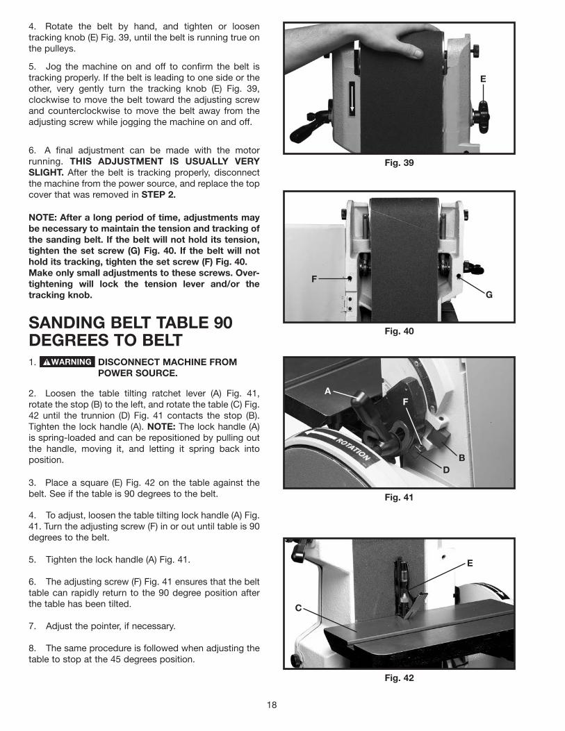
SANDING BELT TABLE 90DEGREES TO BELT1. DISCONNECT MACHINE FROM
POWER SOURCE.
2. Loosen the table tilting ratchet lever (A) Fig. 41,rotate the stop (B) to the left, and rotate the table (C) Fig.42 until the trunnion (D) Fig. 41 contacts the stop (B).Tighten the lock handle (A). NOTE: The lock handle (A)is spring-loaded and can be repositioned by pulling outthe handle, moving it, and letting it spring back intoposition.
NOTE: After a long period of time, adjustments maybe necessary to maintain the tension and tracking ofthe sanding belt. If the belt will not hold its tension,tighten the set screw (G) Fig. 40. If the belt will nothold its tracking, tighten the set screw (F) Fig. 40. Make only small adjustments to these screws. Over-tightening will lock the tension lever and/or thetracking knob.
Fig. 40
Fig. 41
Fig. 42
3. Place a square (E) Fig. 42 on the table against thebelt. See if the table is 90 degrees to the belt.
4. To adjust, loosen the table tilting lock handle (A) Fig.41. Turn the adjusting screw (F) in or out until table is 90degrees to the belt.
5. Tighten the lock handle (A) Fig. 41.
6. The adjusting screw (F) Fig. 41 ensures that the belttable can rapidly return to the 90 degree position afterthe table has been tilted.
7. Adjust the pointer, if necessary.
8. The same procedure is followed when adjusting thetable to stop at the 45 degrees position.
E
G
F
A
BD
F
E
C

19
MITER GAUGE SLOT ONBELT SANDER TABLEPARALLEL TO SANDING BELT1. DISCONNECT MACHINE FROM
POWER SOURCE.
2. Position the table (A) (Figs. 43 and 44) 90 degrees tothe belt. Place a square (B) in the miter gauge slot withthe blade (C) of the square touching the sanding belt.Check the opposite end of the belt to see if the mitergauge slot (D) is parallel to the belt.
3. To adjust, loosen the three (3) screws (E) Fig. 45,located underneath the table. Move the table (A) until themiter gauge slot is parallel to the sanding belt. Tightenthe three (3) screws (E).NOTE: When making this adjustment, make sure thatthe table lock lever is tightened.
MAINTAIN A MAXIMUM DISTANCE OF1/16" BETWEEN THE SANDING BELTAND THE TABLE.
Fig. 43 Fig. 44
Fig. 45
CHANGING POSITION OFSANDING ARM1. DISCONNECT MACHINE FROM
POWER SOURCE.
2. The sanding arm (A) can be used in the verticalposition (Fig. 46), the horizontal position (Fig. 47), or anyangle in between. Loosen the lock lever (B), position thearm (A) to the desired angle, and tighten the lock lever(B).
3. The top idler pulley cover (C) Figs. 46 and 47 can beremoved to clear the workpiece when sanding in thehorizontal position. For a long workpiece, lower thedeflector plate (D) to clear the workpiece. Raise thedeflector plate (D) to deflect saw dust when sanding ashort workpiece.NOTE: With the sanding arm (A) in the horizontalposition (Fig. 47), use the table (E) or the accessorybackstop to support the work.
Fig. 47
Fig. 46
A
B C
D
CB
D
A
E
B
E
C
A
E
DC
A B

SANDING DISC TABLE 90DEGREES TO DISC1. DISCONNECT MACHINE FROM
POWER SOURCE.
2. Loosen the two disc table lock handles, the left oneis shown at (A) Fig. 48, and move the table (B) until theit contacts the table stop screw (C) on the left side of thetable. Tighten the lock handles.
Fig. 48
Fig. 49
3. Place a square (E) Fig. 49 on the table and againstthe sanding disc. See if the table is 90 degrees to thedisc.
4. To adjust, loosen the lock handles (A) Fig. 48, andtighten or loosen the table stop screw (C) Fig. 48 untilthe table is 90 degrees to the disc.
5. Adjust sanding disc table pointer, if necessary
TILTING THE DISC SANDER TABLE1. DISCONNECT MACHINE FROM
POWER SOURCE.
2. To tilt the table, loosen the disc table lock handles,one of which is shown at (A) Fig. 48, and move the tableto the desired angle and tighten the lock handles.
DISC TABLE MITER GAUGESLOT PARALLEL TOSANDING DISC1. DISCONNECT MACHINE FROM
POWER SOURCE.
2. With the table (A) Fig. 50 positioned 90 degrees tothe disc, place a square (B) in the miter gauge slot withthe blade of the square touching the sanding disc.
3. Use a pencil to mark the disc where the square (B)Fig. 50 contacts the disc, and measure the distancefrom the disc to the miter gauge slot.
4. Rotate the disc to the other end of the table. Use asquare to check the distance between the miter gaugeslot and the mark on the disc made in STEP 3. Makesure that the distances are the same.
5. To adjust, loosen the four screws, on the tabletrunnions, two of which are shown at (D) Fig. 51. Adjustthe table until the miter gauge slot is parallel to the disc.Tighten the four screws (D).NOTE: When making this adjustment, make surethat the table lock handle is tightened.
MAINTAIN A MAXIMUM DISTANCE OF1/16" BETWEEN THE SANDING DISCAND THE TABLE.
Fig. 50
Fig. 51
A
C
E
B
A
B
D
20

21
DUST PORT COVERThe abrasive finishing machine is equipped with amanually operated dust port cover (A) Fig. 52, whichmust be adjusted to suit the sanding operation.
1. DISCONNECT MACHINE FROM POWER SOURCE.
2. If you are sanding with the disc, push in on dust portcover (A) Fig. 52.
3. If you are sanding on the belt, pull dust port cover(A) Fig. 53, outward.
Fig. 52
Fig. 53
OPERATIONSABRASIVE BELTS & DISCS -THEIR SELECTION AND USEDelta supplies a wide range of belts and discs for use on your Belt and Disc Finishing Machine. These belts and discsare recommended for a wide range of work on wood, metals, plastics and other materials. However, when a largeamount of production work of one kind is to be done, it is best to call in a coated abrasive specialist for specific beltand disc recommendations.
A wide variety of materials may be processed on a dry belt or disc. But for professional quality or for production worka low melting point grease should be used for cooler cutting, better finish, and for longer belt life. Even coarse beltswill "load" when grinding aluminum dry, and so a lubricant should always be used for this material. To a varying degree,this is true of other non-ferrous metals like soft brass and zinc.
A grease stick is often applied to the belt or disc to prevent "loading" of the belt on softer materials especiallyaluminum. When grinding steel or some kinds of plastic, the grease stick is often used to prevent over-heating of thework piece. Many times a single belt is used for both stock removal and for finish, just by lubricating one half of thebelt with light grease for stock removal and the other side or half of the belt with a heavy grease for polishing to bringout a good finish. This can be done only when the parts are very small and need not be moved across the face of thebelt.
When an abrasive belt smaller than 6" is desired, the 6" belt can be split. This can be done by turning the belt insideout and with a knife or other sharp instrument cut a slot in the belt at the desired width. Then proceed to tear the belt.
A
A

22
SANDING INSIDE CURVES
2. Loosen the two lock knobs (A) Fig. 37, and removethe top cover (B).
3. Inside curves can be sanded on the top sandingdrum, as shown in Fig. 56.
REPLACE THE TOP COVER (A) FIG. 37,WHEN SANDING INSIDE CURVES IS COMPLETE.
1. DISCONNECT MACHINE FROM POWER SOURCE.
Fig. 56
SURFACING OR EDGESANDING WITH SANDING BELT
Fig. 54
Fig. 55
When surfacing (see Fig. 54), or edge sanding (see Fig.55), the sanding arm is in the horizontal position and thetable (A) Fig. 54 and Fig. 55, must always be used toprevent the workpiece from being carried along the belt.Always hold the workpiece firmly, keeping your fingersaway from the sanding belt. Always keep the end of theworkpiece against the table and move the workpieceevenly across the sanding belt. Apply only enoughpressure to allow the sanding belt to remove material.Use extra caution when sanding very thin pieces.
THE EDGE OF THE TABLE MUST BEPOSITIONED A MAXIMUM OF 1/16INCH AWAY FROM THE SANDING BELTTO AVOID TRAPPING THE WORK ORFINGERS BETWEEN THE TABLE ANDSANDING BELT.
ONLY TEAR THE BELT A FEW INCHES AT A TIME ONE WAY THEN REVERSE THE TEARINGACTION. THIS METHOD WILL REDUCE THE TENDENCY OF THE BELT TO UNRAVEL.
For certain applications, a mist coolant attachment (not supplied by Delta) will be helpful. If the use of a mist coolantcauses the Abrasive Belt to slip on the lower drive pulley, this can be corrected by using a "tire" which can behomemade by wrapping the pulley with a piece of coated abrasive belt. The grit is, of course, turned to the outsideand cement should be used sparingly to avoid lumps under the "tire."
A
A

23
END SANDINGWITH THE BELTWhen sanding the ends of wide workpieces it is moreconvenient to use the sanding belt with the sanding armin the vertical position as shown in Fig. 57.
THE EDGE OF THE TABLE MUST BEPOSITIONED A MAXIMUM OF 1/16 INCH AWAYFROM THE SANDING BELT TO AVOID TRAPPINGTHE WORK OR FINGERS BETWEEN THE TABLE ANDSANDING BELT.
Fig. 57
SANDING OUTSIDE CURVESOutside curves should be sanded on the sanding disc asshown in Fig. 58.
ALWAYS SAND ON THE LEFT(DOWNWARD) SIDE OF THE SANDING DISC, ASSHOWN. SANDING ON THE RIGHT (UPWARD) SIDEOF THE SANDING DISC COULD CAUSE THEWORKPIECE TO FLY UP WHICH COULD BEHAZARDOUS.
THE EDGE OF THE TABLE MUST BEPOSITIONED A MAXIMUM OF 1/16 INCH AWAYFROM THE SANDING DISC TO AVOID TRAPPINGTHE WORK OR FINGERS BETWEEN THE TABLEAND SANDING DISC.
Fig. 58
END SANDINGWITH THE DISCWhen sanding the ends of narrow workpieces use thesanding disc, as shown in Fig. 59. Move the work fromthe center to the left side of the sanding disc.
ALWAYS SAND ON THE LEFT (DOWN-WARD) SIDE OF THE SANDING DISC, AS SHOWN.SANDING ON THE RIGHT (UPWARD) SIDE OF THESANDING DISC COULD CAUSE THE WORKPIECE TOFLY UP WHICH COULD BE HAZARDOUS.
THE EDGE OF THE TABLE MUST BEPOSITIONED A MAXIMUM OF 1/16 INCH AWAYFROM THE SANDING DISC TO AVOID TRAPPINGTHE WORK OR FINGERS BETWEEN THE TABLE ANDSANDING DISC.
Fig. 59

24
CIRCLE SANDING WITH DISC
1. DISCONNECT MACHINE FROM POWER SOURCE.
A circle sanding attachment is supplied with the sander.It enables the operator to sand circles up to 24" indiameter. Follow the guidelines below to attach andoperate the circle sanding attachment.
2. Insert the stop block (A) Fig. 60 into the slot in thesanding disc table. Line up the end of the outside edge(B) of the block to the diameter of the circle shown onthe scale. Tighten the screw in the stop block with a5/32 hex wrench (C) to hold the block (A) in place.
Fig. 60
3. Insert the guide pin (D) Fig. 61 into the center of theoversized rough cut circle (E).
Fig. 61
4. Insert the guide pin (D) Fig. 61 into the slot (F) of thedisc sander table. Rotate the workpiece (E) Fig. 62.continuously while sanding. A correctly sized circle issanded when the guide pin (D) Fig.60 contacts the stopblock, (A) Fig. 60.
Fig. 62
5. When necessary, adjust the scale (F) Fig. 63 byloosening the two screws (G), adjusting the scale in orout, and tightening the two screws.
Fig. 63
A
BC
D
EF
E
F
G
G

25
MAINTENANCEREPLACING SANDING BELT1. DISCONNECT MACHINE FROM
POWER SOURCE.
2. Loosen the two lock knobs (A) Fig. 64, and removethe top cover (B).
Fig. 64
3. Loosen the two lock knobs (C) Fig. 65 enough toallow the back panel (D) Figs. 64 and 65, to open. NOTE:The lock knobs (C) cannot be removed.
Fig. 65
4. Release the belt tension by turning the hand lever(E) Fig. 64. Slide the belt (F) Fig. 66 off of both sandingdrums.
Fig. 66
5. Slide the new sanding belt over both sandingdrums. Ensure that the belt runs in the direction of thearrow, printed on the inside of the belt.
6. Apply tension to the sanding belt and replace thetop cover removed in STEP 2.
7. Close the back panel (D) Figs. 64 and 65, andtighten the two lock knobs (C) Fig. 65 that wereloosened in STEP 3.
8. Check the belt tracking before applying power to thesander.
REPLACING SANDING DISCSee the section “ABRASIVE DISC” in the “ASSEMBLY”section of this manual.
A A
B
C
C
D
D
E
F

26
OVERLOAD PROTECTIONThe motor supplied with your sander is equipped with areset overload relay button (A) Fig. 67. If the motor shutsoff or fails to start because of overloading (sanding tooheavy, using a worn sanding belt or disc, using thesander beyond its capacity), or low voltage, turn thepower switch to the “OFF” position. Let the motor coolthree to five minutes and push the reset button (A) Fig.67. Start the motor.
Fig. 67
A complete line of accessories is available from your Delta Supplier, Porter-Cable • Delta Factory Service Centers,and Delta Authorized Service Stations. Please visit our Web Site www.deltamachinery.com for a catalog orfor the name of your nearest supplier.
Since accessories other than those offered by Delta have not been tested with this product, use of suchaccessories could be hazardous. For safest operation, only Delta recommended accessories should beused with this product.
ACCESSORIESPOWER TAKE-OFF SHAFT1. DISCONNECT MACHINE FROM
POWER SOURCE.
2. A power take-off shaft is provided on the lower endof the sanding belt arm to accommodate accessories.
3. For access to the power take-off shaft, remove thetwo screws (B) Fig. 68, and cover (C).
4. Fig. 69 shows the power take-off shaft (A).
UNGUARDED ROTATING SHAFTS (A)FIG 69 CAN CREATE AN ENTANGLEMENT HAZARD.ALWAYS COVER THE POWER TAKE-OFF SHAFTWHEN NOT USING ACCESSORIES.
Fig. 68
Fig. 69
A
B B
C
A

27
PARTS, SERVICE OR WARRANTY ASSISTANCEAll Delta Machines and accessories are manufactured to high quality standards and are serviced by a networkof Porter-Cable • Delta Factory Service Centers and Delta Authorized Service Stations. To obtain additionalinformation regarding your Delta quality product or to obtain parts, service, warranty assistance, or the locationof the nearest service outlet, please call 1-800-223-7278 (In Canada call 1-800-463-3582).
Two Year Limited New Product WarrantyDelta will repair or replace, at its expense and at its option, any new Delta machine, machine part, or machine accessorywhich in normal use has proven to be defective in workmanship or material, provided that the customer returns the productprepaid to a Delta factory service center or authorized service station with proof of purchase of the product within twoyears and provides Delta with reasonable opportunity to verify the alleged defect by inspection. For all refurbished Deltaproduct, the warranty period is 180 days. Delta may require that electric motors be returned prepaid to a motormanufacturer’s authorized station for inspection and repair or replacement. Delta will not be responsible for any asserteddefect which has resulted from normal wear, misuse, abuse or repair or alteration made or specifically authorized byanyone other than an authorized Delta service facility or representative. Under no circumstances will Delta be liable forincidental or consequential damages resulting from defective products. This warranty is Delta’s sole warranty and setsforth the customer’s exclusive remedy, with respect to defective products; all other warranties, express or implied, whetherof merchantability, fitness for purpose, or otherwise, are expressly disclaimed by Delta.

The following are trademarks of PORTER-CABLE·DELTA (Las siguientes son marcas registradas de PORTER-CABLE S.A.): Auto-Set®,BAMMER®, B.O.S.S.®, Builder’s Saw®, Contractor’s Saw®, Contractor’s Saw II™, Delta®, DELTACRAFT®, DELTAGRAM™, Delta Series2000™, DURATRONIC™, Emc²™, FLEX®, Flying Chips™, FRAME SAW®, Homecraft®, INNOVATION THAT WORKS®, Jet-Lock®,JETSTREAM®, ‘kickstand®, LASERLOC®, MICRO-SET®, Micro-Set®, MIDI LATHE®, MORTEN™, NETWORK™, OMNIJIG®, POCKETCUTTER®, PORTA-BAND®, PORTA-PLANE®, PORTER-CABLE®&(design), PORTER-CABLE®PROFESSIONAL POWER TOOLS, Posi-Matic®,Q-3®&(design), QUICKSAND®&(design), QUICKSET™, QUICKSET II®, QUICKSET PLUS™, RIPTIDE™&(design), SAFE GUARD II®, SAFE-LOC®, Sanding Center®, SANDTRAP®&(design), SAW BOSS®, Sawbuck™, Sidekick®, SPEED-BLOC®, SPEEDMATIC®, SPEEDTRONIC®,STAIR EASE®, The American Woodshop®&(design), The Lumber Company®&(design), THE PROFESSIONAL EDGE®, THE PROFESSIONALSELECT®, THIN-LINE™, TIGER®, TIGER CUB®, TIGER SAW®, TORQBUSTER®, TORQ-BUSTER®, TRU-MATCH™, TWIN-LITE®,UNIGUARD®, Unifence®, UNIFEEDER™, Unihead®, Uniplane™, Unirip®, Unisaw®, Univise®, Versa-Feeder®, VERSA-PLANE® , WHISPERSERIES®, WOODWORKER’S CHOICE™. Trademarks noted with ™ and ® are registered in the United States Patent and Trademark Office and may also be registered in othercountries. Las Marcas Registradas con el signo de ™ y ® son registradas por la Oficina de Registros y Patentes de los Estados Unidos ytambién pueden estar registradas en otros países.
PORTER-CABLE • DELTA SERVICE CENTERS(CENTROS DE SERVICIO DE PORTER-CABLE • DELTA)
Parts and Repair Service for Porter-Cable • Delta Machinery are Available at These Locations(Obtenga Refaccion de Partes o Servicio para su Herramienta en los Siguientes Centros de Porter-Cable • Delta)
Authorized Service Stations are located in many large cities. Telephone 800-438-2486 or 731-541-6042 for assistance locating one.Parts and accessories for Porter-Cable·Delta products should be obtained by contacting any Porter-Cable·Delta Distributor, AuthorizedService Center, or Porter-Cable·Delta Factory Service Center. If you do not have access to any of these, call 800-223-7278 and you willbe directed to the nearest Porter-Cable·Delta Factory Service Center. Las Estaciones de Servicio Autorizadas están ubicadas en muchasgrandes ciudades. Llame al 800-438-2486 ó al 731-541-6042 para obtener asistencia a fin de localizar una. Las piezas y los accesoriospara los productos Porter-Cable·Delta deben obtenerse poniéndose en contacto con cualquier distribuidor Porter-Cable·Delta, Centrode Servicio Autorizado o Centro de Servicio de Fábrica Porter-Cable·Delta. Si no tiene acceso a ninguna de estas opciones, llame al800-223-7278 y le dirigirán al Centro de Servicio de Fábrica Porter-Cable·Delta más cercano.
ARIZONATempe 85282 (Phoenix)2400 West Southern AvenueSuite 105Phone: (602) 437-1200Fax: (602) 437-2200
CALIFORNIAOntario 91761 (Los Angeles)3949A East Guasti RoadPhone: (909) 390-5555Fax: (909) 390-5554San Leandro 94577 (Oakland)3039 Teagarden StreetPhone: (510) 357-9762Fax: (510) 357-7939
COLORADOArvada 80003 (Denver)8175 Sheridan Blvd., Unit SPhone: (303) 487-1809Fax: (303) 487-1868
FLORIDADavie 33314 (Miami)4343 South State Rd. 7 (441)Unit #107Phone: (954) 321-6635Fax: (954) 321-6638
Tampa 33609 4538 W. Kennedy BoulevardPhone: (813) 877-9585Fax: (813) 289-7948
GEORGIAForest Park 30297 (Atlanta)5442 Frontage Road,Suite 112Phone: (404) 608-0006Fax: (404) 608-1123
ILLINOISAddison 60101 (Chicago)400 South Rohlwing Rd.Phone: (630) 424-8805Fax: (630) 424-8895
Woodridge 60517 (Chicago)2033 West 75th StreetPhone: (630) 910-9200Fax: (630) 910-0360
MARYLANDElkridge 21075 (Baltimore)7397-102 Washington Blvd.Phone: (410) 799-9394Fax: (410) 799-9398
MASSACHUSETTSBraintree 02185 (Boston)719 Granite StreetPhone: (781) 848-9810Fax: (781) 848-6759Franklin 02038 (Boston)Franklin Industrial Park101E Constitution Blvd.Phone: (508) 520-8802Fax: (508) 528-8089
MICHIGANMadison Heights 48071 (Detroit)30475 Stephenson HighwayPhone: (248) 597-5000Fax: (248) 597-5004
MINNESOTAMinneapolis 554295522 Lakeland Avenue NorthPhone: (763) 561-9080Fax: (763) 561-0653
MISSOURINorth Kansas City 641161141 Swift AvenuePhone: (816) 221-2070Fax: (816) 221-2897
St. Louis 631197574 Watson RoadPhone: (314) 968-8950Fax: (314) 968-2790
NEW YORKFlushing 11365-1595 (N.Y.C.)175-25 Horace Harding Expwy.Phone: (718) 225-2040Fax: (718) 423-9619
NORTH CAROLINACharlotte 282709129 Monroe Road, Suite 115Phone: (704) 841-1176Fax: (704) 708-4625
OHIOColumbus 432144560 Indianola AvenuePhone: (614) 263-0929Fax: (614) 263-1238
Cleveland 441258001 Sweet Valley DriveUnit #19Phone: (216) 447-9030Fax: (216) 447-3097
OREGONPortland 972304916 NE 122 nd Ave.Phone: (503) 252-0107Fax: (503) 252-2123
PENNSYLVANIAWillow Grove 19090520 North York RoadPhone: (215) 658-1430Fax: (215) 658-1433
TEXASCarrollton 75006 (Dallas)1300 Interstate 35 N, Suite 112Phone: (972) 446-2996Fax: (972) 446-8157
Houston 770384321 Sam Houston Parkway,WestSuite 180Phone: (281) 260-8887Fax: (281) 260-9989
WASHINGTONAuburn 98001(Seattle)3320 West Valley HWY, NorthBuilding D, Suite 111Phone: (253) 333-8353Fax: (253) 333-9613
Printed in U.S.A. PC-0603-149
CANADIAN PORTER-CABLE • DELTA SERVICE CENTERSALBERTABay 6, 2520-23rd St. N.E.Calgary, AlbertaT2E 8L2Phone: (403) 735-6166Fax: (403) 735-6144
BRITISH COLUMBIA8520 Baxter PlaceBurnaby, B.C.V5A 4T8Phone: (604) 420-0102Fax: (604) 420-3522
MANITOBA1699 Dublin AvenueWinnipeg, ManitobaR3H 0H2Phone: (204) 633-9259Fax: (204) 632-1976
ONTARIO505 Southgate DriveGuelph, OntarioN1H 6M7Phone: (519) 767-4132Fax: (519) 767-4131
QUÉBEC1515 ave.St-Jean Baptiste, Suite 160Québec, QuébecG2E 5E2Phone: (418) 877-7112Fax: (418) 877-7123
1447, BeginSt-Laurent, (Montréal),QuébecH4R 1V8Phone: (514) 336-8772Fax: (514) 336-3505