6-band, 12-port, 65°, xpol, panel antenna, variable tilt ... · ret device is factory confi gured...
TRANSCRIPT

12-Port Antenna698-960 | 698-960 | 1427-2180 | 1427-2180 | 2490-2690 | 2490-2690 MHz
PR
OD
UC
T O
VE
RV
IEW
Frequency Range (MHz) 698-960 698-960 1427-2180 1427-2180 2490-2690 2490-2690
Array R1 R2 B1 B2 Y1 Y2
Connector 1-2 3-4 5-6 7-8 9-10 11-12
Polarization XPOL XPOL XPOL XPOL XPOL XPOL
Azimuth Beamwidth (avg) 65° 65° 65° 65° 65° 65°
Electrical Downtilt 2-12° 2-12° 2-12° 2-12° 2-12° 2-12°
Dimensions 1945 x 432 x 175 mm
Quoted performance parameters are provided to offer typical, peak or range values only and may vary as a result of normal testing, manufacturing and operational conditions. Extreme operational conditions and/or stress on structural supports is beyond our control. Such conditions may result in damage to this product. Improvements to products may be made without notice.
REV062618A CONNECTING PEOPLE + TECHNOLOGYwww.amphenol-antennas.com
1 of 7
Twin tri band antenna, dual polarisation, 12 connectors
Independent tilt on each band 2-12° / 2-12° / 2-12° / 2-12° / 2-12° / 2-12°
Lightweight Twin+™, next generation TwinLine™ platform and low windload
MET and RET versions, 3GPP/AISG2.0, in multiple single RET (multiple device type1) or in Multi-RET (device type 17, with fi rmware above MD3.10).
Our patented, RET module controlling all tilt angles, fully inserted inside the antenna (fi eld replaceable)
5978600P5978600PG 5978600PDx
6-Band, 12-Port, 65°, XPOL, Panel Antenna, Variable Tilt, 1945 mm
65° 1945 mm
+Next Generation
ORDERING OPTIONS Select from the different options listed below
SELECT ELECTRICAL DOWNTILT CONTROL & AISG PROTOCOL
SELECT ACTUATOR
SELECT CONNECTOR TYPE
ANTENNA MODEL NUMBER
Manual Electrical Tilt (MET) --- 4.3-10 Female 5978600P
Remote Electrical Tilt (RET)AISG v2.0 / 3GPP
Multi-Device Control Unit (MDCU) 4.3-10 Female 5978600PG
Multi-Device Dual Unit(MDDU) 4.3-10 Female 5978600PDx*
*Pre-commissioned confi guration; Contact Amphenol for further details.
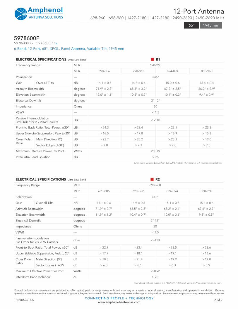
ELECTRICAL SPECIFICATIONS Ultra Low Band R1
Frequency Range MHz 698-960
MHz 698-806 790-862 824-894 880-960
Polarization --- ±45°
Gain Over all Tilts dBi 14.1 ± 0.5 14.8 ± 0.4 15.0 ± 0.6 15.4 ± 0.4
Azimuth Beamwidth degrees 71.9° ± 2.2° 68.3° ± 3.2° 67.2° ± 2.5° 66.2° ± 2.9°
Elevation Beamwidth degrees 12.0° ± 1.1° 10.5° ± 0.7° 10.1° ± 0.3° 9.4° ± 0.9°
Electrical Downtilt degrees 2°-12°
Impedance Ohms 50
VSWR --- < 1.5
Passive Intermodulation3rd Order for 2 x 20W Carriers dBm < -110
Front-to-Back Ratio, Total Power, ±30° dB > 24.3 > 23.4 > 23.1 > 23.8
Upper Sidelobe Suppression, Peak to 20° dB > 16.5 > 17.8 > 16.9 > 15.3
Cross Polar Ratio
Main Direction (0°) dB > 22.7 > 25.2 > 23.1 > 19.0
Sector Edges (±60°) dB > 7.0 > 7.3 > 7.0 > 7.0
Maximum Effective Power Per Port Watts 250 W
Inter/Intra Band Isolation dB > 25
Standard values based on NGMN-P-BASTA version 9.6 recommendation.
Quoted performance parameters are provided to offer typical, peak or range values only and may vary as a result of normal testing, manufacturing and operational conditions. Extreme operational conditions and/or stress on structural supports is beyond our control. Such conditions may result in damage to this product. Improvements to products may be made without notice.
REV062618A CONNECTING PEOPLE + TECHNOLOGYwww.amphenol-antennas.com
2 of 7
12-Port Antenna698-960 | 698-960 | 1427-2180 | 1427-2180 | 2490-2690 | 2490-2690 MHz
5978600P5978600PG 5978600PDx
6-Band, 12-Port, 65°, XPOL, Panel Antenna, Variable Tilt, 1945 mm
65° 1945 mm
ELECTRICAL SPECIFICATIONS Ultra Low Band R2
Frequency Range MHz 698-960
MHz 698-806 790-862 824-894 880-960
Polarization --- ±45°
Gain Over all Tilts dBi 14.1 ± 0.6 14.9 ± 0.5 15.1 ± 0.5 15.4 ± 0.4
Azimuth Beamwidth degrees 71.9° ± 2.7° 68.5° ± 2.8° 68.2° ± 2.4° 67.6° ± 2.7°
Elevation Beamwidth degrees 11.9° ± 1.2° 10.4° ± 0.7° 10.0° ± 0.6° 9.3° ± 0.5°
Electrical Downtilt degrees 2°-12°
Impedance Ohms 50
VSWR --- < 1.5
Passive Intermodulation3rd Order for 2 x 20W Carriers dBm < -110
Front-to-Back Ratio, Total Power, ±30° dB > 22.9 > 23.4 > 23.5 > 23.6
Upper Sidelobe Suppression, Peak to 20° dB > 17.7 > 18.1 > 19.1 > 16.6
Cross Polar Ratio
Main Direction (0°) dB > 18.8 > 21.4 > 19.9 > 17.8
Sector Edges (±60°) dB > 6.3 > 6.1 > 6.3 > 5.9
Maximum Effective Power Per Port Watts 250 W
Inter/Intra Band Isolation dB > 25
Standard values based on NGMN-P-BASTA version 9.6 recommendation.

Quoted performance parameters are provided to offer typical, peak or range values only and may vary as a result of normal testing, manufacturing and operational conditions. Extreme operational conditions and/or stress on structural supports is beyond our control. Such conditions may result in damage to this product. Improvements to products may be made without notice.
REV062618A CONNECTING PEOPLE + TECHNOLOGYwww.amphenol-antennas.com
3 of 7
12-Port Antenna698-960 | 698-960 | 1427-2180 | 1427-2180 | 2490-2690 | 2490-2690 MHz
5978600P5978600PG 5978600PDx
6-Band, 12-Port, 65°, XPOL, Panel Antenna, Variable Tilt, 1945 mm
65° 1945 mm
ELECTRICAL SPECIFICATIONS Filtered Array (Y1) B1
Frequency Range MHz 1427-2180
MHz 1427-1518 1695-1880 1850-1990 1920-2180
Polarization --- ±45°
Gain Over all Tilts dBi 15.5 ± 0.4 16.4 ± 0.5 16.5 ± 0.5 16.8° ± 0.5
Azimuth Beamwidth degrees 70.5° ± 2.0° 68.3° ± 3.1° 65.0° ± 2.5° 63.4° ± 2.9°
Elevation Beamwidth degrees 8.3° ± 0.4° 6.9° ± 0.5° 6.5° ± 0.4° 6.0° ± 0.7°
Electrical Downtilt degrees 2°-12°
Impedance Ohms 50
VSWR --- < 1.5
Passive Intermodulation3rd Order for 2 x 20W Carriers dBm < -110
Front-to-Back Ratio, Total Power, ±30° dB > 25.9 > 28.5 > 31.0 > 29.6
Upper Sidelobe Suppression, Peak to 20° dB > 13.3 > 15.6 > 14.7 > 13.4
Cross Polar Ratio
Main Direction (0°) dB > 17.5 > 20.0 > 22.3 > 20.9
Sector Edges (±60°) dB > 9.1 > 7.1 > 8.9 > 8.2
Maximum Effective Power Per Port Watts 200 W
Inter/Intra Band Isolation dB > 28
Standard values based on NGMN-P-BASTA version 9.6 recommendation.
ELECTRICAL SPECIFICATIONS Filtered Array (Y2) B2
Frequency Range MHz 1427-2180
MHz 1427-1518 1695-1880 1850-1990 1920-2180
Polarization --- ±45°
Gain Over all Tilts dBi 15.6 ± 0.4 16.4 ± 0.4 16.5 ± 0.5 16.8 ± 0.5
Azimuth Beamwidth degrees 70.1° ± 2.0° 67.8° ± 2.3° 66.2° ± 2.1° 63.7° ± 3.6°
Elevation Beamwidth degrees 8.1° ± 0.5° 6.8° ± 0.4° 6.4° ± 0.4° 5.9° ± 0.7°
Electrical Downtilt degrees 2°-12°
Impedance Ohms 50
VSWR --- < 1.5
Passive Intermodulation3rd Order for 2 x 20W Carriers dBm < -110
Front-to-Back Ratio, Total Power, ±30° dB > 26.7 > 27.5 > 29.4 > 28.5
Upper Sidelobe Suppression, Peak to 20° dB > 13.1 > 16.3 > 15.1 > 14.4
Cross Polar Ratio
Main Direction (0°) dB > 19.6 > 19.0 > 19.5 > 17.3
Sector Edges (±60°) dB > 8.4 > 7.4 > 9.2 > 8.5
Maximum Effective Power Per Port Watts 200 W
Inter/Intra Band Isolation dB > 28
Standard values based on NGMN-P-BASTA version 9.6 recommendation.
Quoted performance parameters are provided to offer typical, peak or range values only and may vary as a result of normal testing, manufacturing and operational conditions. Extreme operational conditions and/or stress on structural supports is beyond our control. Such conditions may result in damage to this product. Improvements to products may be made without notice.Quoted performance parameters are provided to offer typical, peak or range values only and may vary as a result of normal testing, manufacturing and operational conditions. Extreme operational conditions and/or stress on structural supports is beyond our control. Such conditions may result in damage to this product. Improvements to products may be made without notice.
REV062618A CONNECTING PEOPLE + TECHNOLOGYwww.amphenol-antennas.com
4 of 7
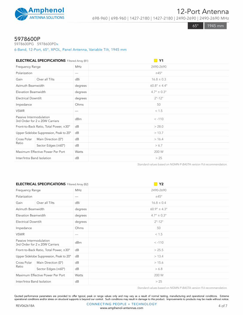
ELECTRICAL SPECIFICATIONS Filtered Array (B1) Y1
Frequency Range MHz 2490-2690
Polarization --- ±45°
Gain Over all Tilts dBi 16.8 ± 0.3
Azimuth Beamwidth degrees 60.8° ± 4.4°
Elevation Beamwidth degrees 4.7° ± 0.3°
Electrical Downtilt degrees 2°-12°
Impedance Ohms 50
VSWR --- < 1.5
Passive Intermodulation3rd Order for 2 x 20W Carriers dBm < -110
Front-to-Back Ratio, Total Power, ±30° dB > 28.0
Upper Sidelobe Suppression, Peak to 20° dB > 13.7
Cross Polar Ratio
Main Direction (0°) dB > 16.4
Sector Edges (±60°) dB > 6.7
Maximum Effective Power Per Port Watts 200 W
Inter/Intra Band Isolation dB > 25
Standard values based on NGMN-P-BASTA version 9.6 recommendation.
12-Port Antenna698-960 | 698-960 | 1427-2180 | 1427-2180 | 2490-2690 | 2490-2690 MHz
5978600P5978600PG 5978600PDx
6-Band, 12-Port, 65°, XPOL, Panel Antenna, Variable Tilt, 1945 mm
65° 1945 mm
ELECTRICAL SPECIFICATIONS Filtered Array (B2) Y2
Frequency Range MHz 2490-2690
Polarization --- ±45°
Gain Over all Tilts dBi 16.8 ± 0.4
Azimuth Beamwidth degrees 60.9° ± 4.3°
Elevation Beamwidth degrees 4.7° ± 0.3°
Electrical Downtilt degrees 2°-12°
Impedance Ohms 50
VSWR --- < 1.5
Passive Intermodulation3rd Order for 2 x 20W Carriers dBm < -110
Front-to-Back Ratio, Total Power, ±30° dB > 25.5
Upper Sidelobe Suppression, Peak to 20° dB > 13.4
Cross Polar Ratio
Main Direction (0°) dB > 15.6
Sector Edges (±60°) dB > 6.8
Maximum Effective Power Per Port Watts 200 W
Inter/Intra Band Isolation dB > 25
Standard values based on NGMN-P-BASTA version 9.6 recommendation.
Quoted performance parameters are provided to offer typical, peak or range values only and may vary as a result of normal testing, manufacturing and operational conditions. Extreme operational conditions and/or stress on structural supports is beyond our control. Such conditions may result in damage to this product. Improvements to products may be made without notice.Quoted performance parameters are provided to offer typical, peak or range values only and may vary as a result of normal testing, manufacturing and operational conditions. Extreme operational conditions and/or stress on structural supports is beyond our control. Such conditions may result in damage to this product. Improvements to products may be made without notice.
REV062618A CONNECTING PEOPLE + TECHNOLOGYwww.amphenol-antennas.com
5 of 7
12-Port Antenna698-960 | 698-960 | 1427-2180 | 1427-2180 | 2490-2690 | 2490-2690 MHz
5978600P5978600PG 5978600PDx
6-Band, 12-Port, 65°, XPOL, Panel Antenna, Variable Tilt, 1945 mm
65° 1945 mm
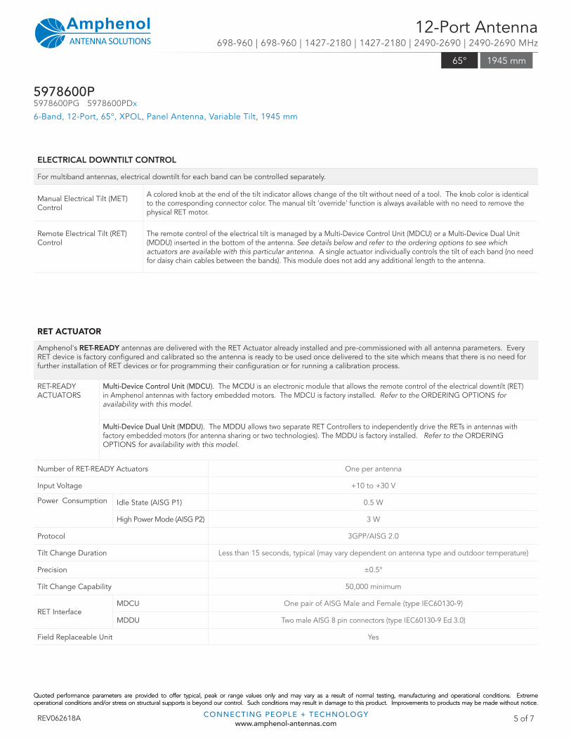
ELECTRICAL DOWNTILT CONTROL
For multiband antennas, electrical downtilt for each band can be controlled separately.
Manual Electrical Tilt (MET) Control
A colored knob at the end of the tilt indicator allows change of the tilt without need of a tool. The knob color is identical to the corresponding connector color. The manual tilt 'override' function is always available with no need to remove the physical RET motor.
Remote Electrical Tilt (RET) Control
The remote control of the electrical tilt is managed by a Multi-Device Control Unit (MDCU) or a Multi-Device Dual Unit (MDDU) inserted in the bottom of the antenna. See details below and refer to the ordering options to see which actuators are available with this particular antenna. A single actuator individually controls the tilt of each band (no need for daisy chain cables between the bands). This module does not add any additional length to the antenna.
RET ACTUATOR
Amphenol's RET-READY antennas are delivered with the RET Actuator already installed and pre-commissioned with all antenna parameters. Every RET device is factory confi gured and calibrated so the antenna is ready to be used once delivered to the site which means that there is no need for further installation of RET devices or for programming their confi guration or for running a calibration process.
RET-READY ACTUATORS
Multi-Device Control Unit (MDCU). The MCDU is an electronic module that allows the remote control of the electrical downtilt (RET) in Amphenol antennas with factory embedded motors. The MDCU is factory installed. Refer to the ORDERING OPTIONS for availability with this model.
Multi-Device Dual Unit (MDDU). The MDDU allows two separate RET Controllers to independently drive the RETs in antennas with factory embedded motors (for antenna sharing or two technologies). The MDDU is factory installed. Refer to the ORDERING OPTIONS for availability with this model.
Number of RET-READY Actuators One per antenna
Input Voltage +10 to +30 V
Power Consumption Idle State (AISG P1) 0.5 W
High Power Mode (AISG P2) 3 W
Protocol 3GPP/AISG 2.0
Tilt Change Duration Less than 15 seconds, typical (may vary dependent on antenna type and outdoor temperature)
Precision ±0.5°
Tilt Change Capability 50,000 minimum
RET InterfaceMDCU One pair of AISG Male and Female (type IEC60130-9)
MDDU Two male AISG 8 pin connectors (type IEC60130-9 Ed 3.0)
Field Replaceable Unit Yes
AR
RA
Y L
AY
OU
T
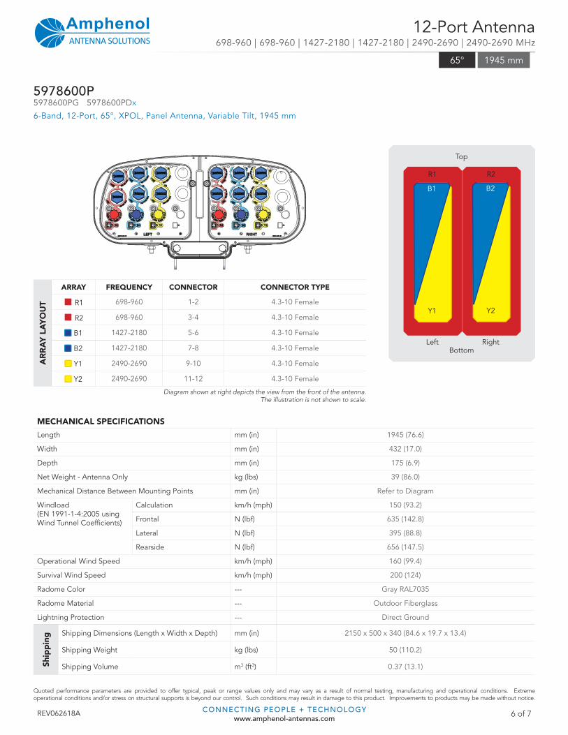
ARRAY FREQUENCY CONNECTOR CONNECTOR TYPE
R1 698-960 1-2 4.3-10 Female
R2 698-960 3-4 4.3-10 Female
B1 1427-2180 5-6 4.3-10 Female
B2 1427-2180 7-8 4.3-10 Female
Y1 2490-2690 9-10 4.3-10 Female
Y2 2490-2690 11-12 4.3-10 Female
Diagram shown at right depicts the view from the front of the antenna. The illustration is not shown to scale.
Quoted performance parameters are provided to offer typical, peak or range values only and may vary as a result of normal testing, manufacturing and operational conditions. Extreme operational conditions and/or stress on structural supports is beyond our control. Such conditions may result in damage to this product. Improvements to products may be made without notice.
REV062618A CONNECTING PEOPLE + TECHNOLOGYwww.amphenol-antennas.com
6 of 7
MECHANICAL SPECIFICATIONS
Length mm (in) 1945 (76.6)
Width mm (in) 432 (17.0)
Depth mm (in) 175 (6.9)
Net Weight - Antenna Only kg (lbs) 39 (86.0)
Mechanical Distance Between Mounting Points mm (in) Refer to Diagram
Windload(EN 1991-1-4:2005 using Wind Tunnel Coeffi cients)
Calculation km/h (mph) 150 (93.2)
Frontal N (lbf) 635 (142.8)
Lateral N (lbf) 395 (88.8)
Rearside N (lbf) 656 (147.5)
Operational Wind Speed km/h (mph) 160 (99.4)
Survival Wind Speed km/h (mph) 200 (124)
Radome Color --- Gray RAL7035
Radome Material --- Outdoor Fiberglass
Lightning Protection --- Direct Ground
Ship
pin
g Shipping Dimensions (Length x Width x Depth) mm (in) 2150 x 500 x 340 (84.6 x 19.7 x 13.4)
Shipping Weight kg (lbs) 50 (110.2)
Shipping Volume m3 (ft3) 0.37 (13.1)
12-Port Antenna698-960 | 698-960 | 1427-2180 | 1427-2180 | 2490-2690 | 2490-2690 MHz
5978600P5978600PG 5978600PDx
6-Band, 12-Port, 65°, XPOL, Panel Antenna, Variable Tilt, 1945 mm
65° 1945 mm
Top
BottomLeft Right
R1
Y2
B2
Y1
B1
R2
Quoted performance parameters are provided to offer typical, peak or range values only and may vary as a result of normal testing, manufacturing and operational conditions. Extreme operational conditions and/or stress on structural supports is beyond our control. Such conditions may result in damage to this product. Improvements to products may be made without notice.
ENVIRONMENTAL SPECIFICATIONS
Environmental Standard --- ETS 300 019
Operating Temperature ° C (° F) -40° to +60° (-40° to 140°)
Product Environmental Compliance --- Product is RoHs Compliant
REV062618A CONNECTING PEOPLE + TECHNOLOGYwww.amphenol-antennas.com
7 of 7
ACCESSORIES All accessories are ordered separately unless otherwise indicated
ITEM MODEL NUMBER WEIGHT
Brackets for pole Ø48 to Ø115 mm (Ø1.9 to Ø4.5 in) delivered as standard 0900181/00 3.4 kg (7.5 lbs)
Brackets for pole Ø70 to Ø150 mm (Ø2.8-Ø5.9 in) optional 0900182/00 3.9 kg (8.6 lbs)
Kit to add mechanical tilt (0° to 10°) to above brackets optional 0900396/00 2.3 kg (5.1 lbs)
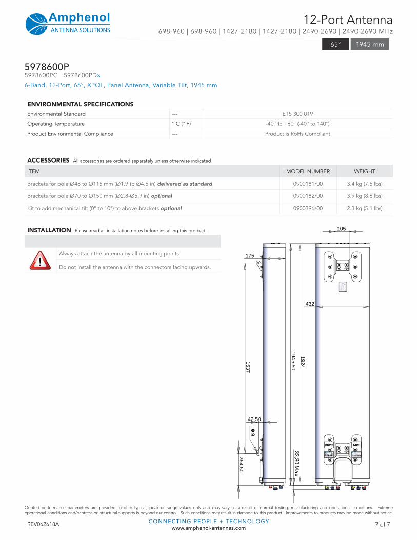
175
9
42,50
1537 254,50
432
105
1945,50
33,30 Max
1924
INSTALLATION Please read all installation notes before installing this product.
Always attach the antenna by all mounting points.
Do not install the antenna with the connectors facing upwards.
12-Port Antenna698-960 | 698-960 | 1427-2180 | 1427-2180 | 2490-2690 | 2490-2690 MHz
5978600P5978600PG 5978600PDx
6-Band, 12-Port, 65°, XPOL, Panel Antenna, Variable Tilt, 1945 mm
65° 1945 mm