5sm6 afd unit - low & medium voltage - siemens
TRANSCRIPT

Answers for infrastructure and cities.
5SM6 AFD Unit Technology Primer
SENTRON


Preface
Be it protecting, switching, measuring or monitoring – components for low-voltage power distribution from Siemens offer you just the right device for all applications in the electrical installation field. Whether for use in industry, infrastructure or buildings, these products guarantee a maximum of flexibility, ease of use and safety – helping you to keep the entire power supply safely under control.
Protective devices such as fuses, MCBs and RCDs have been tried and tested over many years, but they are not suitable for detecting arcing faults and particularly not those which are limited by an impedance. This safety gap is now closed by a new protective device for the detection of arcing faults: the 5SM6 AFD (Arc Fault Detection) unit. 5SM6 AFD units detect arcing faults of the type which can arise at serial fault locations and unsecured contacts or as the result of insulation faults between one active conductor and another or between an active conductor and the protective conductor. This contributes very effectively to preventing fires caused by electricity.
In this primer we describe not only the physical properties of arcs but also the design and mode of operation of the AFD unit. We also present the various versions of the device and a number of application examples in order to make it easier for you to select the right unit and use it correctly.
1

2
CONTENTS1 Introduction 04
2 Firestatisticsandcausesoffire 04
3 Protectivedevices 10
3.1 Arcing faults and established protective devices 10
3.2 The expanded protection concept 12
4 Ignitionandburningconditionsofthearc 13
5 Concreteexamplesoffaultsituationswithserialarcs 15
5.1 Fault situation range up to 3 A arcing current 15
5.2 Fault situation range from 3 A to 10 A arcing current 18
5.3 Fault situation range over 10 A arcing current 20
5.4 Impact of load current on the outbreak of fire 20
6 Faultsituationwithparallelarcingfaults 22
6.1 Basic considerations 22
6.2. Shutdown behavior of overcurrent protective devices 23
6.3 Assessment 25
7 Detectionofarcingfaults 26
7.1 Basic design of the 5SM6 AFD unit 26
7.2 Detection of serial arcing faults 27
7.3 Detection of parallel arcing faults 28
7.4 Prevention of unwanted trippings 29
3
8 StandardsandrequirementsforAFDunits 33
8.1 General principles 33
8.2 Product standard 33
8.3 Installation regulations 34
9 Productdescriptionofthe5SM6AFDunit 35
9.1 Product versions 35
9.2 General properties 36
9.3 Special properties 37
10 Guide 39
10.1 Installation of the AFD unit 39
10.2 Procedure after the AFD unit has tripped 39
11 Applicationexamples 41
12 Outlook 42
13 Sourcesandliterature 43
Listoffiguresandtables 44
4
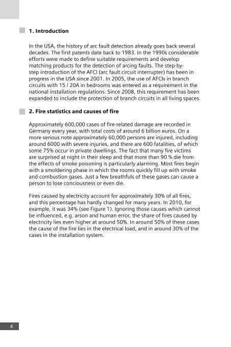
1.Introduction
In the USA, the history of arc fault detection already goes back several decades. The first patents date back to 1983. In the 1990s considerable efforts were made to define suitable requirements and develop matching products for the detection of arcing faults. The step-by-step introduction of the AFCI (arc fault circuit interrupter) has been in progress in the USA since 2001. In 2005, the use of AFCIs in branch circuits with 15 / 20A in bedrooms was entered as a requirement in the national installation regulations. Since 2008, this requirement has been expanded to include the protection of branch circuits in all living spaces.
2.Firestatisticsandcausesoffire
Approximately 600,000 cases of fire-related damage are recorded in Germany every year, with total costs of around 6 billion euros. On a more serious note approximately 60,000 persons are injured, including around 6000 with severe injuries, and there are 600 fatalities, of which some 75% occur in private dwellings. The fact that many fire victims are surprised at night in their sleep and that more than 90 % die from the effects of smoke poisoning is particularly alarming. Most fires begin with a smoldering phase in which the rooms quickly fill up with smoke and combustion gases. Just a few breathfuls of these gases can cause a person to lose conciousness or even die.
Fires caused by electricity account for approximately 30% of all fires, and this percentage has hardly changed for many years. In 2010, for example, it was 34% (see Figure 1). Ignoring those causes which cannot be influenced, e.g. arson and human error, the share of fires caused by electricity lies even higher at around 50%. In around 50% of these cases the cause of the fire lies in the electrical load, and in around 30% of the cases in the installation system.

0%
34%
2%8%
3%
18%3%
1%
9%
22%
Causes of fire (2010)Lightning strike
Electricity
Explosion
Arson
Activities with a fire risk
Human error
Open fire
Self-ignition
Overheating
Other / unknown
Figure 1: Causes of fire in Germany in 2010
It is also interesting to look at the defect statistics drawn up by VdS (VdS Schadenverhütung GmbH) on the basis of more than 30,000 company inspections. Figure 2 presents a breakdown of the more than 150,000 defects discovered. Multiple defects in the systems mean that totals can exceed 100%:
48%
42%
30%
30%26%25%
24%
20%
20%
19%
16%
12%
12%
11%11%
VdS -
Type of electrical equipment not permittedTechnical documents not complete/not availableProtection against direct contact not assuredCables and cable routing poorLabeling of circuits and electrical equipment missing/incompleteEquipment damagedEquipment poorly fastenedWall and ceiling penetrations poorConductor terminals and connections poorEquipment with electrical faults/overloadsEquipotential bonding missing/poorAccess ways, doors and operating aisles poorType of electrical equipment inadequateCleanliness of the electrical installation inadequateCable entries on electrical equipment poor
Statistics of defects in electrical systems (2007)
Figure 2: Statistics of defects in electrical systems (2007)
5

6
With many of the discovered defects, e.g. poor cable routing or wall/ceiling penetration, fires can also be caused by arcing faults which are not detected by the protective devices in place.The statistics published for Germany are applicable in similar magnitude to other European countries. However, there are differences in the way the data are collected and processed. Figures 3 to 5 present a number of examples of fire statistics. Here again, fires can be caused by arcing faults which result from the discovered defects such as rodent damage, loose connections, aging or damage with moisture.
15%
11%
9%
2%37%
9%
17%
Damage and moisture
Rodent damage
Material faults
Aging
Loose connections
Insulation faults
Application faults
Figure 3: Denmark: Fire statistics 2005; absolute number: 16,551 fires
Other
Installation errors
Overload
Loose connections
Short circuits / ground faults
65%
4%4%
1%
26%
Figure 4: Finland: Fire statistics 2006; absolute number: 1,860 fires
7
Other
Short circuits / ground faults
Leakage current
Arcing
30%
3%3%
64%
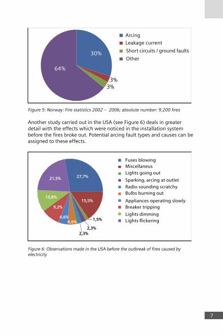
Figure 5: Norway: Fire statistics 2002 – 2006; absolute number: 9,200 fires
Another study carried out in the USA (see Figure 6) deals in greater detail with the effects which were noticed in the installation system before the fires broke out. Potential arcing fault types and causes can be assigned to these effects.
9,2%
10,8%
21,5% 27,7%
15,5%
2,3%2,3%
1,5%4,6%
4,6%
Fuses blowingMiscellaneusLights going out
Sparking, arcing at outletRadio sounding scratchyBulbs burning out
Appliances operating slowlyBreaker tripping
Lights dimmingLights flickering
Figure 6: Observations made in the USA before the outbreak of fires caused by electricity

The fault situations indicated by the statistics are equally evident in practice. The following faults (and prohibited work practices) are frequently discovered in electrical installation systems and in the area downstream from the socket outlet.
a) Damaged cable insulation, e. g. due to nails, screws or clips
Figure 7: Nail or screw
Figure 8: Overtight clip
b) Cables with too tight a bending radius are at risk of breaking.
Figure 9: Too tight a bending radius
8

9
c) Arcing faults can be caused in cables which are routed through open windows or doors and then crushed when the windows or doors are closed, leaving the insulation damaged.
Figure 10: Crushed cable
d) Damage or aging of the insulation due to environmental influences such as UV radiation, temperature, moisture, gases
f) Rodent damageg) Loose contacts, e.g. due to too low a torque
h) Conductors damaged by claw fasteners
The fire statistics, the defects observed and their effects are strong arguments for developing a suitable protective device such as the AFD unit as a contribution to reducing the number of fires caused by arcing faults.
10
3. Protectivedevices
3.1 Arcingfaultsandestablishedprotectivedevices
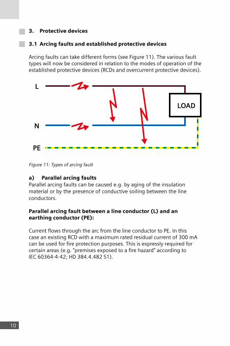
Arcing faults can take different forms (see Figure 11). The various fault types will now be considered in relation to the modes of operation of the established protective devices (RCDs and overcurrent protective devices).
L
N
PE
LOAD
Figure 11: Types of arcing fault
a) ParallelarcingfaultsParallel arcing faults can be caused e.g. by aging of the insulation material or by the presence of conductive soiling between the line conductors.
Parallelarcingfaultbetweenalineconductor(L)andanearthingconductor(PE):
Current flows through the arc from the line conductor to PE. In this case an existing RCD with a maximum rated residual current of 300 mA can be used for fire protection purposes. This is expressly required for certain areas (e.g. "premises exposed to a fire hazard" according to IEC 60364-4-42; HD 384.4.482 S1).
11
Overcurrent protective devices provide no protection in some cases because the impedances in the faulty circuit may be too high. It is then impossible to meet the shutdown conditions with the short times needed to limit the energy at the fault location to values which would prevent an outbreak of fire.
Parallelarcingfaultbetweenonelineconductorandanotherorbetweenalineconductorandaneutralconductor:
RCDs are unsuitable for protection purposes in this case because no current flows through PE or earth.Overload and short circuit protective devices such as MCBs can provide protection only under certain conditions. Success depends on the impedances in the faulty circuit, including the value of the arc voltage, and on whether the shutdown conditions for such current/time values are fulfilled, thus limiting the energy at the fault location to values which would prevent an outbreak of fire. High impedance values limit the current level and can prevent timely shutdown particularly at fault locations with high contact resistances or when extension cables are used downstream from the socket outlet (see also section 6).
b) Serialarcingfaultinanactiveconductor:In this case no current flows to PE or earth, and the load current is even reduced on account of the arc voltage in series with the useful load. RCDs and overcurrent protective devices can provide no protection therefore in this case.
To sum up it can be said that no protection at all exists for the case of a serial arcing fault, and that the protection level needs to be improved for parallel arcing faults between active conductors. To close these safety gaps, the Siemens protection concept for low-voltage power distribution has been expanded to include the 5SM6 AFD unit.

12
3.2 Theexpandedprotectionconceptforthepreventionoffires
As already mentioned, protective devices for the detection of arcing faults (AFCIs: Arc Fault Circuit Interrupters according to UL 1699) were introduced in the USA several years ago and are required for branch circuits in residential buildings. In other countries, including Germany, the standards refer to these protective devices as AFDDs (Arc Fault Detection Devices). The 5SM6 AFD unit from Siemens expands the existing protection concept for the reduction of fires caused by electricity, which is based on RCDs and overcurrent protective devices, and closes the safety gap which has existed up to now.
Figure 12 shows the situation for the individual fault types with regard to protective devices according to UL standards (e.g. USA) and IEC or EN standards (e.g. Germany).
Type of fault
Serial
Parallel
Line conductor–Neutral/Line conductor–Line conductor
Line conductor–Protective conductor
Parallel
Protection according to IEC standard
Protection according to UL standard
AFDD
AFDDMCB AFCIMCB
AFDDRCD AFCIRCD
AFCI
L
L
L
N
N
N
LOAD
LOAD
LOAD
NEW
NEW
NEW
Figure 12: Fault types and protective devices suitable for fire protection - MCB: Miniature Circuit Breaker- RCD: Residual Current Device- AFDD: Arc Fault Detection Device - AFCI: Arc Fault Circuit Interrupter (USA)
The properties of arcs and the function and mode of operation of the 5SM6 AFD unit are described in the following sections.

13
4. Ignitionandburningconditionsofthearc
So-called "contact arcs" (see Figure 13) can result from direct or indirect contact between metal parts at fault locations which are in motion or have little conductivity. Movement (vibration, thermal expansion) of the metal parts, which were originally in direct contact with each other, results in arcing, heating and ultimately a fused link. Through further heating and repeat breaking of the fused link, unstable arcs are formed briefly. The results are high temperatures on the metal parts (electrodes). The air is ionized, and after the arc is extinguished in the current zero crossing it is ignited again. Combustible materials in the vicinity (e.g. cable insulation) are carbonized.
Figure 13: Contact arc
If the insulation between two conductors is damaged, parallel arcing faults can form over a conductive insulating clearance even without direct metal contact (see Figure 14).If there are materials between the conductors, the insulation properties can be impaired due to aging and chemical, thermal or mechanical loading. Leakage currents can form on surfaces which are contaminated by dirt or condensation. These leakage currents and short discharges can heat up and carbonize the plastics. High temperatures at the fault location can cause a part of the carbonized material to vaporize, greatly heating up the surroundings and igniting a stable arc. The carbonized path between the electric conductors enables the arc to be re-ignited after the current zero crossing, with further heating up to the outbreak of a fire.

1414
Figure 14: Arc over a conductive insulating clearance
The outbreak of a fire as the result of a serial arcing fault will be described using the example of a constriction in a cable. The current flow results in higher temperatures at the constriction. This increase in temperature causes hot copper to oxidize, leading in turn to an increase in resistance and even higher temperatures, and in some cases to melting of the copper. Gas is formed, particularly at the peak current point. This results at least briefly in an air gap with arcing. The insulation at the fault location is carbonized. Over this clearance it is possible for a stable arc to burn and for the resulting flames to cause a fire (see Figure 15).
Figure 15: Outbreak of a fire due to serial arcs

15
5. Concreteexamplesoffaultsituationswithserialarcs
Serial arcs were tested under laboratory conditions with various loads using 230 V to earth (the usual voltage in Europe) and NYM-J cable (the most widely used cable type in Europe). Definitions of terms used in the analysis and presentation of the conditions:
a) Arc: A luminous discharge of electricity over an insulating medium, which also causes partial vaporization of the electrodes. The electric arc subsequently creates a broad-band high-frequency noise.
b) Arc stability: The ratio of arc duration to observation time over 100 ms. Arc stability is always less than 100 % because of the zero crossings of the AC voltage.
c) Incandescence (incandescent contact): A connection which due to poor contact in the current flow heats up the contact material and causes it to glow. No high-frequency noise is created, and the incandescent contact can be regarded as a serial impedance.
d) First flame: A flame which burns continuously for 5 ms
e) Significant flame: A flame which burns continuously for 50 ms
f) Stable flame: A flame which burns continuously for 500 ms

1616
5.1 Faultsituationrangeupto3Aarcingcurrent
The first graph (energy) illustrates the energy development over the observation time (see Figure 16). Two energy values are presented. The black curve represents the total energy (total electric energy) which is released at the fault location mainly in the form of heat and radiation. The red curve represents the arc energy.The difference between total energy and arc energy is owed mainly to the incandescence. The development of the energy increase can be divided into two phases. In the first phase, the "carbonization phase" (yellow section), it is impossible to create a stable arc if the fault location is not yet carbonized. Short arcs form only when the distance between the conductor ends at the fault location is small enough, i.e. at the moment of contact or interruption. As a result of the low arc stability (bottom graph), the mean value of the power is low and the total energy increases only slowly. During the carbonization phase, the cable sample cannot be ignited but the PVC insulation suffers continuous carbonization.In the second phase, the "ignition phase" (red section), the fault location is carbonized enough and the arc stability increases rapidly to 80%. The arc becomes very stable, the energy increases rapidly, and flame formation begins (penultimate graph).

1717
Figure 16: Development of the arc using the example 2 A / 230 V

18
5.2 Faultsituationrangefrom3Ato10Aarcingcurrent
The graphs can also be divided into a carbonization phase and an ignition phase for these higher arc currents (see Figure 17). Once again the stability of the arc is initially very low because the fault location is still not carbonized. As a result of the low arc stability, the mean value of the power is low and the total energy increases only slowly so that the cable sample cannot be ignited.After a far shorter time than with lower currents, the fault location is carbonized enough and the arc stability increases rapidly to over 90 %. The arc becomes very stable, the energy increases rapidly. After a few seconds the insulation is no longer able to withstand the heat and a flame is formed.During the test the arc voltage is very low at around 15 V to 30 V. This is typical for an arc at low voltage because a serial arc can form only when the gap between the two conductors or electrodes is very small.
18

1919
Figure 17: Development of the arc using the example 5 A / 230 V

2020
5.3 Faultsituationrangeover10Aarcingcurrent
In this range, the power of the arc is so high that flames occur very quickly and without carbonization. Evidently, arcs with high power are unsuitable for effective carbonization of the fault location. The reason lies with the vaporization of the already formed carbonized material, as a result of which the formation of a useful carbon path is prevented. Furthermore, serial arcs with high power are able to weld the two copper conductors together again, thus "healing" the fault location.
5.4 Impactofloadcurrentontheoutbreakoffire
Fire outbreak tests were conducted with load currents in the range from 1 A to 32 A. The following figures show mean values from 100 measurements.
Figure 18: Energy of the significant flame as a function of load current
Figure 19: Outbreak of flames as a function of load current

21
In the low range (below 3 A), the total electric energy which is expended at the fault location mainly in the form of heat and radiation and must be used for the formation of the significant flame is two to three times higher than the energy released by the arc. This energy difference is caused by incandescence. Below 2 A, even a stable arc hardly has enough power to ignite the cable, so the probability of an ignition is greatly reduced.
The probability of arcing faults occurring is greatest in the medium range (3 A to 10 A), which is the category to which most common domestic electrical appliances belong. Here the arc energy is nearly as high as the total electric energy. This is underlined by the dominance of the arc over glowing in this range. In this medium current range, the amount of energy needed to ignite a PVC cable is evidently not dependent on the load current and lies relatively constant at approximately 450 Joule. Here the occurrence of first and significant flames lies at around 80%. In the upper range (above 10 A), the power of the arc is so high that flames occur very quickly and without carbonization. Therefore, significant and stable flames occur more and more rarely. One reason for this is the vaporization of the carbonized material, which prevents the formation of a carbon path. The probability of stable flames drops below 5%. Similarly, arc stability also decreases notably with high load currents. The lower arc stability reduces the power, hardly allowing reliable ignitions to occur. Moreover, high-power serial arcs can sometimes melt the two copper parts back together and "repair" the fault location. Even if stable arcs are rare above 10 A, the short and powerful flames which can occur in this range represent a serious danger.

22
6. Faultsituationwithparallelarcingfaults
6.1 Basicconsiderations
Unlike serial arcing faults, for which no protective devices have been available up to now, parallel arcing faults are detected under certain conditions by other protective devices such as RCDs and overcurrent protective devices (see section 3 and Figure 12).
For the shutting down of parallel arcing faults by overcurrent protective devices it is necessary to consider the system conditions and their impedance values. In the following, the tripping conditions for the overcurrent protective devices (MCB and fuse) are examined to see whether they are sufficient in all cases for providing reliable fire protection.
Figure 20 shows the typical current and voltage curve of a parallel arcing fault. In addition to a stable arc, the current curve can also include rather long gaps without any current flow because the arc is not always re-ignited after the current zero crossing. There is no assurance therefore that the overcurrent protective device will be tripped via the thermal release. Given a high arc voltage in conjunction with a high system impedance, it is well possible for the current peak value to lie below the magnetic tripping current of the MCB.
Figure 20: Current and voltage curve for a parallel arcing fault
22

23
The high arc currents in these cases, which can also exceed 100 A, and the arc voltages in the range of 60 V produce an arc power of several kW (e.g. with 100 A and 60 V the arc power would be 6 kW). This results in high power densities at the fault location, which can lead to rapid ignition of the insulation material and therefore to the outbreak of a fire if shutdown does not take place within fractions of a second.
6.2 Shutdownbehaviorofovercurrentprotectivedevices
From measurements of prospective short circuit currents at socket outlets in office buildings and apartments it is known that the majority of current values lie between 150 A and 500 A.The magnetic quick tripping of the miniature circuit breaker B 16 (within 100 ms) is assured therefore in most cases.
If the fault does not occur at the socket outlet but on the supply line to the socket outlet, the situation will improve thanks to the then lower impedance and the resulting higher short circuit current.
With faults in an extension cable, on the other hand, the impedance will increase and therefore the short circuit current will be notably reduced. The MCB is then no longer able to provide the desired protection.
In all cases, a high arc voltage can also lead to the reduction of the short circuit current and prevent magnetic quick tripping.
Similarly, the shutdown times of the fuses can also be too long for fire protection purposes in critical conditions.
Overcurrent protective devices can work only when the conduction interval for a certain current level lies above the tripping curve of the respective overcurrent protective device.

2424
Figure 21 shows the tripping curves of MCBs for the characteristics B, C and D, as well as the tripping curve of the 5SM6 AFD unit. The tripping times of AFD units offer both supplementary and improved protection against parallel arcing faults in some cross-over areas. As already explained, protection against serial arc faults is provided only by AFD units. MCBs are unsuitable in these cases.
à n-times the rated current (AFD unit with In = 16A)Figure 21: Protection by MCB
25
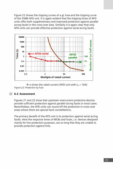
Figure 22 shows the tripping curves of a gL fuse and the tripping curve of the 5SM6 AFD unit. It is again evident that the tripping times of AFD units offer both supplementary and improved protection against parallel arcing faults in the cross-over area. Similarly it is again clear that only AFD units can provide effective protection against serial arcing faults.
à n-times the rated current (AFD unit with In = 16A) Figure 22: Protection by fuse
6.3 Assessment
Figures 21 and 22 show that upstream overcurrent protective devices provide sufficient protection against parallel arcing faults in most cases. Nevertheless, the AFD units can round off the protection in cross-over areas where there are special fault constellations.
The primary benefit of the AFD unit is its protection against serial arcing faults. Here the response times of MCBs and fuses, i.e. devices designed mainly for line protection purposes, are so long that they are unable to provide protection against fires.

26
7. Detectionofarcingfaults
7.1 Basicdesignofthe5SM6AFDunit
Figure 23 shows the basic design of the 5SM6 AFD unit. For detection, all active conductors – in this case the line conductor and the neutral conductor – are passed through the unit and switched. The line conductor is passed through two separate sensors: a current sensor for detecting the low-frequency (line-frequency) signals and an HF sensor for detecting the high-frequency signals. Analog electronics prepares the signals for processing in the microcontroller. The HF power of the current is scanned in the range from 22 to 24 MHz. In the following it is referred to as the RSSI ( Received Signal Strength Indication) and represents the power of the arc at a defined frequency and bandwidth. When the microcontroller sees the criteria for an arcing fault as fulfilled, the tripping signal will be created and directed via a shunt trip to the switching mechanism. In the case of the 5SM6 AFD unit, a mechanical coupling link is actuated to work the mechanism of the mounted MCB or RCBO. The mounted protective device is tripped along with its contacts, and the network is disconnected from the faulty part.
Load Mains
Switching mechanism
Tripping signal
CurrentSensorHF sensor
AFDD
HF noise
Noise power indicator 1V ~25dB
MicrocontrollerAnalog switching
Current with gain & rectified
Current signal
N N
L L
Figure 23: Basic design of the 5SM6 AFD unit
26
27
7.2 Detectionofserialarcingfaults
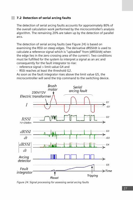
The detection of serial arcing faults accounts for approximately 80% of the overall calculation work performed by the microcontroller's analysis algorithm. The remaining 20% are taken up by the detection of parallel arcs.
The detection of serial arcing faults (see Figure 24) is based on examining the RSSI on steep edges. The derivative dRSSI/dt is used to calculate a reference signal which is "uploaded" from |dRSSI/dt| when the edge lies in the zero crossing area of the current I. Two conditions must be fulfilled for the system to interpret a signal as an arc and consequently for the fault integrator to rise:- reference signal > limit value G4 and- RSSI reaches at least the threshold G2. As soon as the fault integrator rises above the limit value G5, the microcontroller will send the trip command to the switching device.
Figure 24: Signal processing for assessing serial arcing faults

28
To prevent unwanted shutdowns, a distinction must be drawn between arcing faults on the one hand and signals from loads such as brush motors and electronic transformers on the other, which in normal operation produce a high level of HF noise. This is achieved by the fault integrator being reset immediately to zero when certain "arc-untypical" events occur. A characteristic of such an event is for example that the RSSI shows interruptions in the signal curve.
7.3 Detectionofparallelarcingfaults
Serial and parallel arcing faults have different characteristics and are therefore analyzed in different ways. Figure 25 presents an overview of the signal processing.
Figure 25: Signal processing for assessing parallel arcing faults
28

29
The calculation work required of the microcontroller to detect parallel arcing faults is relatively small compared to the overall algorithm, but this is not because less effort is needed to detect parallel arcing faults than serial arcing faults. The reason is rather that some of the signal variables which are calculated for the detection of serial arcs can also be used for parallel arcing faults.
The algorithm for parallel arcing faults calculates not only dRSSI/dtbut also the current derivative dI/dt. The function for detecting parallel arcs does not become active until the value for dI/dt exceeds the threshold value G6. If RSSI > limit G2 is also true, the current half-wave will also be interpreted as an arcing current and the fault integrator will be raised by a value proportional to the arcing current. If some time passes without another arc half-wave occurring, the fault integrator will be decreased again.
If a sufficient number of arc half-waves follow within a certain time window, the fault integrator will reach the threshold G8 and the microcontroller will send the trip command via the mechanical coupling link to the mounted switching device (MCB or RCBO).
7.4 Preventionofunwantedtrippings
For a protective device to be fully accepted, it must not only provide reliable protection against fires caused by electricity but also respond only when there are real faults. For the AFD unit this means that it must distinguish reliably between arcing faults, for which shutdown is required within defined limits, and the operational arcs of electric loads, for which no shutdown should occur.
The examples in Figure 26 show a number of electric loads with high-frequency components in the current, which – particularly in the case of brush sparking on a power drill – lie very close to the signals of an arcing fault.

30
Figure 26: Examples of electric loads with high-frequency signals

31
Other operational faults are e.g.- inrush currents of fluorescent lamps- arcs through thermostat contacts, light switches, plug connectors
There should be no tripping of the AFD unit for any of these operationally created signals, nor for arcing faults in an adjacent circuit.
To reliably decide whether shutdown is necessary for an arcing fault, a number of factors are considered and compared with known fault signals (see Figure 27).
Background le
vel +15dB
95%
80%
Switch
Brush motor
Old relay
Dimmer
Power line
HF stability
SynchronizationHF-power
1,5A Current value60
% o
f IEC
cur
veD
urat
ion
of in
cide
nt
Arcing fault
Figure 27: Factors for the detection of an arcing fault
If the microcontroller analysis of the factors listed in Figure 27 reveals that the signal does not lie in the red field for "arcing fault", the decision will be "no shutdown". What has been detected is an operational status of an electric load.
For greater reliability against unwanted trippings, the high-frequency background noise existing in installation systems was also taken into account.

32
Figure 28 shows high values of this background noise in the frequency range from 15 to 18 MHz. The range from 22 to 24 MHz is scanned therefore in the 5SM6 AFD unit. This frequency range shows particularly little noise and has a large difference in level between background noise and arc noise.
Figure 28: High-frequency noise: Background noise and arcs
The described analysis parameters and criteria are based on experience with AFCIs in the USA and on comprehensive laboratory investigations and simulations. The applicability of the findings in practical conditions was confirmed in comprehensive field tests.
32

3333
8. StandardsandrequirementsforAFDunits
8.1 Generalprinciples
IEC 60364-1 / HD 60364-1 defines the area of application, purpose and principles which apply to the configuration of low-voltage installations. Section 131.3 "Protection against thermal effects" requires the electric system to be arranged such that it presents no risk of combustible material igniting as the result of high temperature or an arc.This can only mean that protection must be provided against hazards which can result from arcs. In the past, a suitable protective device for this purpose was not available for circuits in low-voltage installations. This gap is filled by the AFD unit.
8.2 Productstandard
DIN EN 62606 (VDE 0665-10) / IEC 62606 will be the product standard valid for AFD units. The 5SM6 AFD unit was developed in accordance with this standard. The standard describes the usual requirements and tests, e.g. switching capacity, service live, heating and EMC, as applied for other protective devices (RCDs and MCBs).
Special test devices are described for testing the tripping in connection with serial and parallel arcing faults. The required shutdown times are then also tested under the defined conditions.
The shutdown times for small arcing currents (typical for serial arcs) are defined as a function of the arcing fault current level (see Table 1)
Test arcing current 2.5 A 5 A 10 A 16 A 32 A
Maximum shutdown time 1 s 0.5 s 0.25 s 0.15 s 0.12 s
Table 1: Shutdown times for small arcing currents
With the values from 2.5 A to 32 A the tripping curve of the AFD unit for serial arcing faults lies far below the thermal tripping curves for MCBs and fuses (see Figure 21 and 22). Fire protection is implemented using these low response values and short shutdown times. The tripping curves for parallel and serial arcing faults are identical in this current range.

34
The tripping condition defined for high arcing currents (see table 2) is not a fixed tripping time but a number of arc half-waves which are allowed to occur within 0.5 s. This is because of the often sporadic occurrence and unstable behavior of the parallel arcing fault with high currents. As explained in section 6.2, fuses and MCBs can also provide protection against parallel arcing faults at and above certain current levels, as long as their shutdown conditions are fulfilled.
Test arcing current 75 A 100 A 150 A 200 A 300 A 500 A
Maximum number of half-waves
12 10 8 8 8 8
Table 2: Shutdown times for parallel arcing faults
In addition, special tests are performed on the tripping behavior during an arcing fault and simultaneous operation of various types of equipment in order to check that the unit works correctly. When the equipment is in operation, no shutdown must occur elsewhere if no arcing fault exists there.
8.3 Installationregulations
The use of AFD units is not yet specified in the regulations for the installation of electrical systems. However, they are cited in DIN VDE 0100-530 "Erection of Low-voltage Installations – Part 530: Selection and Erection of Electrical Equipment – Switchgear and Controlgear" in Section 532.7 "Equipment for arc detection and shutdown (AFDD)", with a note that detailed requirements for arc detection in branch circuits are currently in consultation. Similarly, DIN VDE 0100-420 "Erection of Low-voltage Installations – Part 4-42: Protection for safety – Protection against thermal effects" states that the requirement for arc detection and shutdown devices (AFDD) is "in preparation".The basis for including detailed requirements in these provisions is the valid product standard described in 8.1. The detailed requirements will be included in international installation regulations. In IEC 60364-4-42, Ed3 (international standard related to national standard DIN VDE 0100-420), protection will be demanded as a priority for branch circuits in bedrooms and children's rooms and for all areas where there are combustible building structures. For other areas with an elevated risk of fire the use of AFD units will be recommended.
It is also intended to introduce the use of AFDDs in IEC 60364-5-53 (international standard related to the national DIN VDE 0100-530).
34

3535
9. Productdescriptionofthe5SM6AFDunit
9.1 Productversions
The 5SM6 AFD unit is offered in two versions for two mounting widths. The rated voltage is 230V and the rated current 16 A. The 5SM6 AFD unit must be used in combination with another protective device (an MCB or an RCBO). This combination forms an AFDD (Arc Fault Detection Device).
5SM6011-1The 5SM6 011-1 AFD unit is designed for mounting a compact 5SY60 MCB (1+N in 1 modular width) with rated currents up to max. 16 A.
Advantage: Compactdesign in 2 MW overall width offers advantages during retrofits
Figure 29: 5SM6 011-1 AFD unit with and without a mounted 5SY60 MCB

36
5SM6021-1The 5SM6 021-1 AFD unit is designed for mounting a MCB (1+N in 2 modular widths) from the 5SY series or a 5SU1 RCBO (1+N in 2 modular widths), each with rated currents up to max. 16 A.
Advantage: The solution with an RCBO provides completeprotection against overloads, short circuits, residual currents and fire.
Figure 30: 5SM6 021-1 AFD unit with and without a mounted 5SU1 RCBO or 5SY6 MCB
9.2 Generalproperties
a) Assembly:The 5SM6 AFD unit can be completed on site with the required version of an MCB or RCBO and be mounted on a standard mounting rail easily, quickly and without tools. Many different versions with rated currents up to 16 A and various overcurrent characteristics and switching capacities can be fitted. This makes stock keeping far easier.
b) Tripping: The AFD unit detects and assesses the arcing fault. Tripping is
performed via a working current relay, which trips the mounted MCB or RCBO mechanically via a coupling mechanism. This interrupts the circuit.
c) Infeed: Power is fed into the devices from the bottom. Infeed via a busbar
network, for example, can provide a fast and reliable supply.
d) Additional components: Various additional components such as auxiliary current switches
or fault signal contacts can be connected to the 5SM6 AFD unit. Connection to a higher-level control system is thus possible, and tripping can be reported to a central control room. 36

3737
9.3 Specialproperties
a) Regular functional self-test The 5SM6 AFD unit has an internal self-test function (for diagram see Figure 31).
Load Mains
Switching mechanism
Trippingsignals
Self-testPeriod ~13h
No tripping during self-test
CurrentsensorsHF sensor
AFDD
HF noise
Noise power indicator 1V ~25dB
Watch-dog(period 20ms)
MicrocontrollerAnalog switching
Current with gain & rectified
Current signal
Synthetic current & HF signal
N N
L L
Figure 31: Diagram of the internal self-test function This self-test is automatically initiated every 13 hours in order to test the analog electronics and the detection algorithms. The software in the microcontroller generates synthetic HF and current signals, which are similar to the signals of an arcing fault. These signals are fed into the system's detection path behind the sensors and are assessed by the analog circuit and the microcontroller.
It is now imperative therefore for the microcontroller to create the trip command. During the self test the trip signal for the tripping relay is disabled for a short time (ms) to avoid a real tripping of the device. After a successful test the trippng path is enabled again.
A negative test result will cause the device to be tripped immediately. The self-test will be postponed, however, if there are initial signs of a real arcing fault or if the current consumption in the respective branch circuit is higher than the average.
38
The test concept is rounded off by an external watch-dog which checks the program flow and the firmware integrity every 20ms.
b) Overvoltage protection: If voltage increases between the line conductor and the neutral
conductor occur due to system faults such as neutral conductor interruptions, the AFD unit will switch off at voltages above 275 V. The connected loads are thus protected against possible damage from overvoltage.
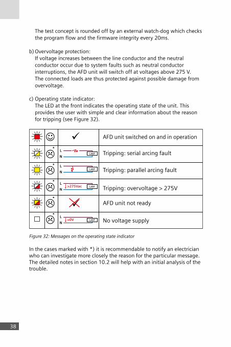
c) Operating state indicator: The LED at the front indicates the operating state of the unit. This
provides the user with simple and clear information about the reason for tripping (see Figure 32).
L
NLAST
AFD unit switched on and in operation
AFD unit not ready
No voltage supply
Tripping: serial arcing fault
Tripping: parallel arcing fault
Tripping: overvoltage > 275V
L
NLAST
L>275Vac
NLAST
L=0V
NLAST
Figure 32: Messages on the operating state indicator
In the cases marked with *) it is recommendable to notify an electrician who can investigate more closely the reason for the particular message. The detailed notes in section 10.2 will help with an initial analysis of the trouble.
38

3939
10. Guide
10.1InstallationoftheAFDunit
The 5SM6 AFD unit is designed for the protection of branch circuits, in particular for lighting and socket outlets. It is installed at the beginning of the circuit in order to protect the entire circuit.It makes sense to assign the unit directly to an individual branching circuit. The following benefits are then possible:- The number of faulty loads and cable segments is limited- It is easier to find the fault location- Unwanted trippings due to superimposed interference are reduced.
10.2ProcedureaftertheAFDunithastripped
As explained in 10.1, clear assignment of the AFD units to individual branch circuits brings benefits when searching for the fault location as it enables an initial narrowing of the search field.The following troubleshooting procedure is recommended after the appearance of the message on the operating state indicator (see Table 3).

40
Symbol Meaning Check/Cause Measure(s)
Serial arcing
a)- Smell test: "Smell of plastic"?- Is discolored plastic visible
(socket outlet, switch, load)?
b) Switch on the AFD unit again. If tripping is repeated within a short time
c) Switch on the AFD unit again à No repeat tripping within a short time:Does a load have a faulty switch or a damaged cable, or is discolor-ation visible on / in the wall (may-be in the neighboring room)?
a) Disconnect the faulty load from the network à Replace or have repaired
b) Disconnect and switch off all the devices (lights) and switch on the AFD unit againà Tripping occurs again: Notify an electricianà No tripping: Switch on and plug in the loads one after the other until tripping occurs à Check whether the device is faulty (notify an electrician if necessary)
c) Actuate the suspicious switch and wait for the reaction of the AFD unità Have it repaired by an electri-cian if necessary.
If the cable is faulty à Have it repaired by an electri-cian.
In case of discoloration: Notify an electrician
If procedure a) to c) brings no results, it is recommendable to have an electrician check the insulation resistance of the system / loads.
Parallel arcing
AFD unit not ready
AFD unit has an internal fault.Call an electrician to test / replace the AFD unit.
Overvoltage > 275 V
There was prolonged overvoltage between L and N.
If the fault reoccurs even after switching on the AFD unit once again, you should ask the power supply company whether it knows of any faults in the infeed. If no fault is known, arrange for an electrician to check the system.
No voltage supply
a) Check whether the general voltage supply is active or b) whether an upstream protective device has interrupted the supply.
a) Wait until the general voltage supply is active again
b) Check the cause of the shutdown (notify an electrician if necessary) and switch on the protective device again after the cause is eliminated.
Table 3: Operating states and recommended actions

41
AFD unit not ready
AFD unit has an internal fault.Call an electrician to test / replace the AFD unit.
11. Applicationexamples
AFD units should be installed at the beginning of branch circuits. In the event of a fault, line conductors and neutral conductors are disconnected from the network in order to achieve the required protection against fire hazards caused by arcs.
The general demand for protection against the hazardous effects of arcing faults as described in section 8.1 applies in particular for places where there is a higher risk.
Here are some concrete examples in which branching circuits should be protected by AFD units, particularly for socket outlets and lighting:
a) The outbreak of a fire is detected too late or not at all and can result in mortal danger for persons in
- bedrooms, children's rooms - old people's homes - kindergartens - schools, universities - hospitals - cinemas
b) In the vicinity there are readily flammable materials used in - houses made of wood or ecological building materials - light-weight structures and wood paneling - loft conversions
c) In the vicinity there are readily flammable materials stored in - stables / barns - joiner's workshops / bakeries - premises with fire risks d) A fire could cause damage to valuable buildings or objects in - libraries - museums - listed buildings
In addition to these examples there are the general risks in older electrical installation systems where there is a particularly high likelihood of loose contacts or damaged insulation.
42
12. Outlook
The 5SM6 AFD unit is a new protective device for electrical installation systems, which effectively helps to reduce fires caused by electricity.
A first contribution is made by devices for protecting single-phase branching circuits with rated currents up to 16 A. They will be followed by versions for branching circuits with higher rated currents and three-phase current applications. In future there will also be a need for arcing protection in direct current applications such as photovoltaics systems.
The use of 5SM6 AFD units in certain installation systems is likely to be demanded by the installation regulations over the next few years.
43
13. Sourcesandliterature
The following sources, links and publications were among those used in drawing up this fire protection primer and can be consulted for additional information:
GDV (Gesamtverband der deutschen Versicherungswirtschaft e.V.): www.gdv.de/Downloads/Schwerpunkte/GDV_Adventsbraende_in_Zahlen_2008-2009.pdfwww.gdv.de/Presse/Archiv_der_Presseveranstaltungen/Presseveranstaltungen_2001/Presseforum_Schaden_und_Unfall_2001/inhaltsseite12184.html
F. Berger, "Der Störlichtbogen – ein Überblick", TU Ilmenau, VDE AKK-Seminar 2009
vfdb Technisch-Wissenschaftlicher Beirat (Arbeitsgruppe Brandschutzforschung) www.sachsen-anhalt.de/fileadmin/Elementbibliothek/Bibliothek_Feuerwehr/idf_dokumente/Kontexmen%c3%bc/Denkschrift_BS-Forschung.pdf)
VdS Schadenverhütung GmbH: www.vds.de/de/
John J. Shea, "Glowing Contact Physics", Eaton Corp., IEEE 2006
JM Martel, "Serielle Störlichtbögen in Elektroinstallationen im Niederspannungsbereich", Siemens AG, AKK-Seminar 2009
M. Anheuser, JM. Martel, Störlichtbögen in der Haustechnik, HDT-Seminar, Munich Dec 2011
JM. Martel, M. Anheuser, A. Hueber, F. Berger, F. Erhardt, "Schutz gegen parallele Störlichtbögen in Hauselektroinstallation", VDE AKK-Seminar 2011
IEC 23E/742/CDV: 2012-02: IEC 62606 Ed. 1.0: General Requirements for Arc Fault Detection Devices (AFDD)
DIN VDE 0100-100:2009-06: Low-Voltage Electrical Installations – Part 1: Fundamental Principles, Assessment of General Characteristics, Definitions
DIN VDE 0100-530:2011-06: Erection of Low-Voltage Installations – Part 530: Selection and Erection of Electrical Equipment – Switchgear and Controlgear

44
Listoffiguresandtables
Page 5, Figure 1: Causes of fire in Germany in 2010
Page 5, Figure 2: Statistics of defects in electrical systems (2007)
Page 6, Figure 3: Denmark: Fire statistics 2005;
absolute number: 16,551 fires
Page 6, Figure 4: Finland: Fire statistics 2006; absolute number: 1,860 fires
Page 7, Figure 5: Norway: Fire statistics 2002 – 2006;
absolute number: 9,200 fires
Page 7, Figure 6: Observations made in the USA before the outbreak of fires
caused by electricity
Page 8, Figure 7: Nail or screw
Page 8, Figure 8: Overtight clip
Page 8, Figure 9: Too tight a bending radius
Page 9, Figure 10: Crushed cable
Page 10, Figure 11: Types of arcing fault
Page 12, Figure 12: Fault types and protective devices suitable for fire protection
Page 13, Figure 13: Contact arc
Page 14, Figure 14: Arc over a conductive insulating clearance
Page 14, Figure 15: Outbreak of a fire due to serial arcs
Page 17, Figure 16: Development of the arc using the example 2 A / 230 V
Page 19, Figure 17: Development of the arc using the example 5 A / 230 V
Page 20, Figure 18: Energy of the significant flame as a function of load current
Page 20, Figure 19: Outbreak of flames as a function of load current
Page 22, Figure 20: Current and voltage curve for a parallel arcing fault
Page 24, Figure 21: Protection by MCB
Page 25, Figure 22: Protection by fuse
Page 26, Figure 23: Basic design of the 5SM6 AFD unit
Page 27, Figure 24: Signal processing for assessing serial arcing faults
Page 28, Figure 25: Signal processing for assessing parallel arcing faults
Page 30, Figure 26: Examples of electric loads with high-frequency signals
Page 31, Figure 27: Factors for the detection of an arcing fault
Page 32, Figure 28: High-frequency noise: Background noise and arcs
Page 33, Table 1: Shutdown times for serial arcing faults
Page 33, Table 2: Shutdown times for parallel arcing faults

45
Page 35, Figure 29: 5SM6 011-1 AFD unit with and without a mounted 5SY60 MCB
Page 36, Figure 30: 5SM6 021-1 AFD unit with and without a mounted 5SU1 RCBO
or 5SY6 MCB
Page 37, Figure 31: Diagram of the internal self-test function
Page 38, Figure 32: Messages on the operating state indicator
Page 41, Table 3: Operating states and recommended actions

46

47

48


Subject to change. The information provided in this brochure contains descriptions or characteristics of performance which in case of actual use do not always apply as described or which may change as a result of further development of the products. An obliga-tion to provide the respective characteris-tics shall only exist if expressly agreed in the terms of contract.
All rights reserved. All product names may be brand names of Siemens Ltd or another supplier whose use by third-parties for their own pur-poses may violate the owner‘s rights.
© Siemens AG 2012
www.siemens.com/lowvoltage/afdd
Siemens AG Infrastructure & Cities Sector Low and Medium Voltage Division Low Voltage & Products P.O. Box 10 09 53 93009 Regensburg Germany
Order No. E10003-E38-2B-G0121-7600 Dispo 25601 • 1212 • PDF only Printed in Germany