5iu.20 00 restrictions its use amdisclose. · impressed-current cathodic protection for...
TRANSCRIPT

TH IS REPOPT HA M W I N I TEID
AND CLEARED FOR P3L I C RELE
LMDE DOm DIREcTIVE 5IU.2000 RESTRICTIONS ARE IPPhD 0
ITS USE AMDISCLOSE.
DISTtIDL'THN STA1'ET A
A*WV wRs PM I rinucDI SR I3 t"ITIE.

.C\i
4 NAVAL SHIP RESEARCH AND DEVELOPMENT CENTER04
Bethesda, Md. 20034
IMPRESSED-CURRENT CATHODIC PROTECTIONFOR SURFACE-EFFECT SHIPS
.- I-
by-P
_ H. P. Hack, B. E.. Miller,
44 and D. A. Davis
44
4
Distribution limited to U.S. Government agencieso only; Test and Evaluation; July 1974. Other re-04quests for this document must be referred to
Chief, Naval Materials Command (PM 17),Washington, D.C. 20362.
C) :.~Q)
.4
raMATERIALS DEPARTMENT J')AG~ '0
,aAnnapolis JE1LT1LJRESEARCH AND DEVELOPMENT REPORT C
u
(I
July 1974 Report 4200$4
The Naval Ship Research and Development Center is a U. S. .%lvy center for laboratoryeffort directed at achieving improved aea and air vehicles. It was formed in March 1967 bymerging the David Taylor Model Basin at Carderock. Maryland with the Marine EngineeringLaboratory at Annapolis, Maryland.
Naval Ship Research and Developm-ent CenterBethesda, Md. 20034
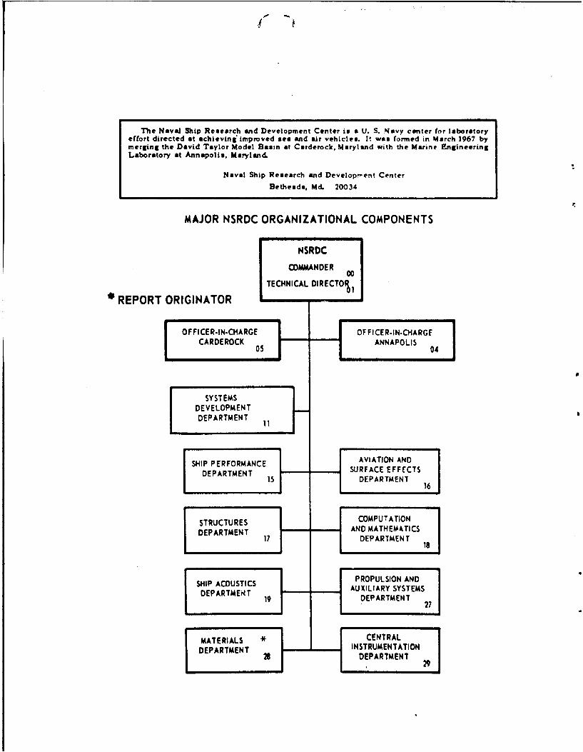
MAJOR NSRDC ORGANIZATIONAL COMPONENTS
NSRDC
COMMANDER 00
TECHNICAL DIRECTOI,
REPORT ORIGINATOR
OFFICER-IN-CHARGE OFFICER-IN-CHARGECARDEROCK ANNAPOLIS 04
SYSTEMSDEVELOPMENTDEPARTMENT
SHIP PERFORMANCE AVIATION ANDPPRFOMNCE SURFACE EFFECTS
DEPARTMENT 13 DEPARTMENT16
STRUCTURES COMPUTATIONAND MATHEMATICSDEPARTMENT 17 DEPARTMENT 18
SHIP ACOUSTICS PROPULSION AND
DEPARTMENT AUXILIARY SYSTEMS19 DEPARTMENT 27
MATERIALS CENTRALDEPARTMENT INSTRUMENTATION
28 DEPARTMENT29
DEPARTMENT OF THE NAVYINAVAL SHIP RESEARCH AND DEVELOPMENT CENTER
BETHESOAMO. =34
IMPRESSED -CURRENT CATHODIC PROTECTIONFOR SURFACE -EFFECT SHIPS
by
H. P. Hack, B. E. Miller,
and D. A. Davis
Distribution limited to U.S. Government agenciesZ only; Test and Evaluation; July 19741. other re-
quests for this document must be referred toChief, Naval Materials Commnand (PM 17), IWashington, D.C. 20362
G AUg96 974
July 19741 Report 4200
ABSTRACT
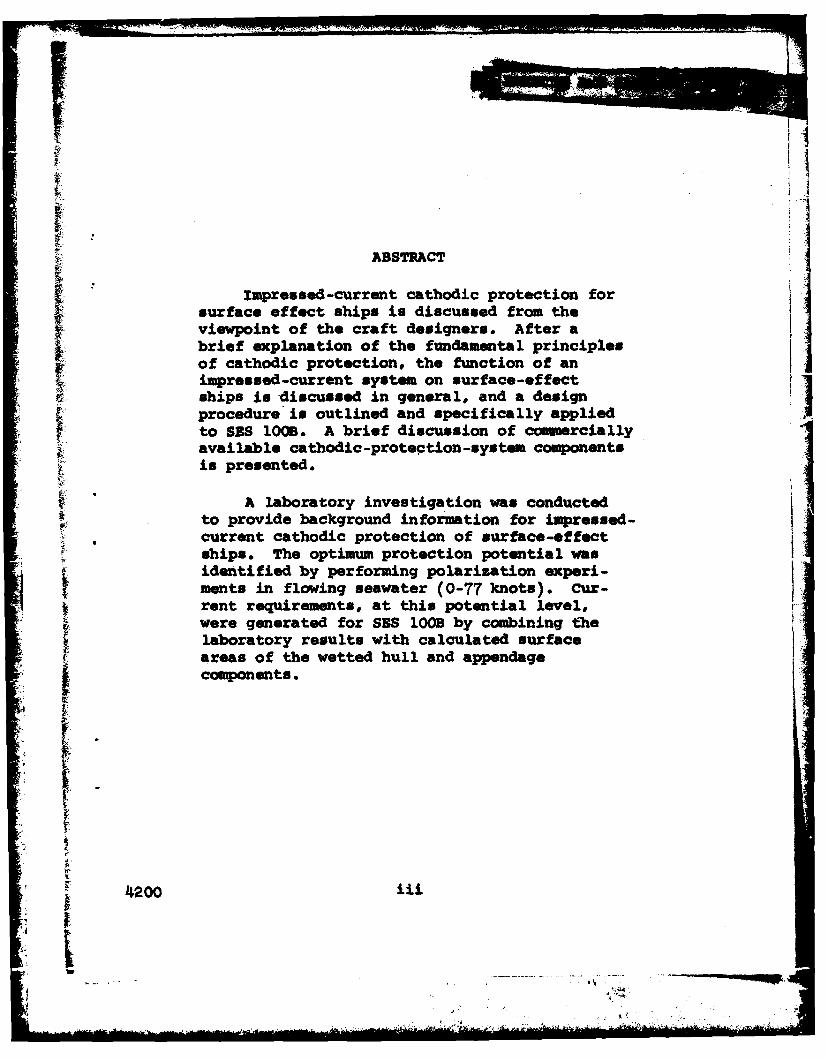
Impressed-current cathodic protection for
surface effect ships is discussed from theviewpoint of the craft designers. After a
f brief explanation of the fundamental principlesof cathodic protection, the function of animpressed-current system on surface-effectships is discussed in general, and a designprocedure is outlined and specifically appliedto SES 100B. A brief discussion of commercially
available cathodic-protection-system componentsis presented.
A laboratory investigation was conductedto provide background information for impressed-
current cathodic protection of surface-effectships. The optimum protection potential wasidentified by performing polarization experi-ments in flowing seawater (0-77 knots). cur-rent requirements, at this potential level,were generated for SBS IOOB by combining thelaboratory results with calculated surfaceareas of the wetted hull and appendagecomponents.
4" 200 l

ADNINISTPATMV ZIOBM&TION
This report was prepared under Work Unit 1-2813-154, Ta3kArea S4629, for the Surface Ef fect Ships Program office(SESPO) titled, "Galvanic Measurements of Surface Effect Ships."This is the final report of the program and constitutes mile-stone 4 of the 1 November 1973 Program Summary.
4200 iv

TABLE OF CONTENTS
ABSTRACT iiiADMINISTRATIVE INFORMATION ivINTRODUCTION 1BASICS OF CATHODIC PROTECTION 1METHODOLOGY - APPROACH TO DESIGN 7METHODOLOGY - APPLICATION TO SES 1OOB 11AVAILABLE COMERCIAL UNITS 18SUMMARY 21LIST OF FIGURES
Figure 1 - Diagram, Galvanic Series of Metalsin Sea Water
Figure 2 - Diagram, Galvanic CouplingFigure 3 - Curve, Polarization CurvesFigure 4 - Diagram, Generalized Impressed
Current Cathodic Protection SystemFigure 5 - Diagram, Anode AssemblyFigure 6 - Diagram, Reference Cell Assembly
APPENDIXESAppendix A - Laboratory Investigations (8 pages)Appendix B - Remote Anode (3 pages)
INITIAL DISTRIBUTION
i II4
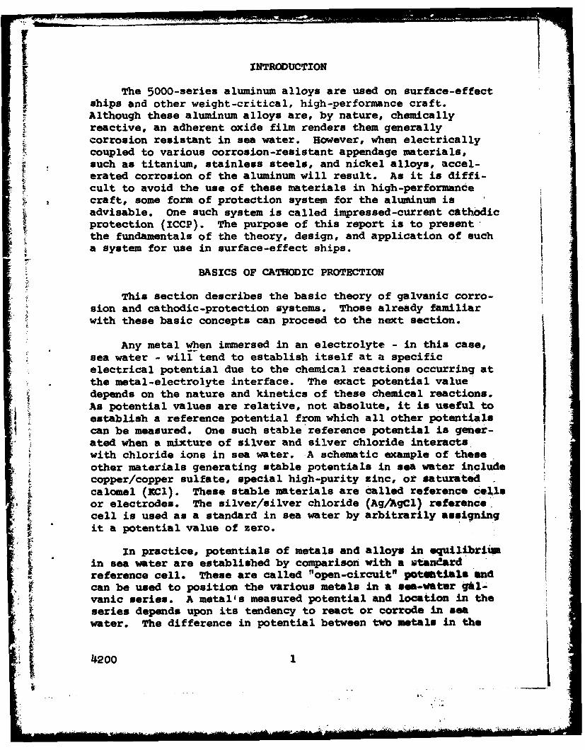
INTRODUCTION
The 5000-series aluminum alloys are used on surface-effect
ships and other weight-critical, high-performance craft.Although these aluminum alloys are, by nature, chemicallyreactive, an adherent oxide film renders them generallycorrosion resistant in sea water. However, when electricallycoupled to various corrosion-resistant appendage materials,
* such as titanium, stainless steels, and nickel alloys, accel-erated corrosion of the aluminum will result. As it is diffi-cult to avoid the use of these materials in high-performancecraft, some form of protection system for the aluminum isadvisable. One such system is called impressed-current cathodicprotection (ICCP). The purpose of this report is to present,the fundamentals of the theory, design, and application of sucha system for use in surface-effect ships.
BASICS OF CATHODIC PROTECTION
This section describes the basic theory of galvanic corro-sion and cathodic-protection systems. Those already familiarwith these basic concepts can proceed to the next section.
Any metal when immersed in an electrolyte - in this case,sea water - will tend to establish itself at a specificelectrical potential due to the chemical reactions occurring atthe metal-electrolyte interface. The exact potential valuedepends on the nature and kinetics of these chemical reactions.As potential values are relative, not absolute, it is useful toestablish a reference potential from which all other potentialscan be measured. One such stable reference potential is gener-ated when a mixture of silver and silver chloride interactswith chloride ions in sea water. A schematic example of theseother materials generating stable potentials in sea water includecopper/copper sulfate, special high-purity zinc, or saturatedcalomel ( d). These stable materials are called reference ceXlsor electrodes. The silver/silver chloride (Ag/AgCl) referencecell is used as a standard in sea water by arbitrarily assigningit a potential value of zero.
in In practice, potentials of metals and alloys in equilibtiiamin sea water are established by comparison with a standardreference cell. These are called "open-circuit" pot~fJAls'andcan be used to position the various metals in a sea-wter gil-vanic series. A metal's measured potential and location in theseries depends upon its tendency to react or corrode in seawater. The difference in potential between two metals in the
00
I f ' ....

series is a measure of the galvanic energy, or driving forceof the corrosion process, which results from electricallycoupling the metals together.
A typical arrangement of common metals in a sea-watergalvanic series appears in figure 1. In this arrangement, amore electronegative (or active) metal, such as aluminum, willsuffer accelerated corrosion when coupled in sea water to amore electropositive (or noble) metal, such as titanium. Thealuminum in such a couple is said to be anodic, and thetitanium is said to be cathodic. Upon electrical coupling ofdissimilar metals, electrons will be transferred from the moreelectronegative to the more electropositive materials, asillustrated in figure 2. This pair of dissimilar metals,electrically connected in sea water, is called a galvaniccouple.
Charge neutrality is maintained by equal electron exchangesat the surface/water interfaces. As electrons flow out of theelectronegative material (anode), it preserves charge neutralityby emitting positively charged metal ions into the sea water,thereby removing material and causing accelerated corrosion.In a galvanic couple, then, the anodic material experiencesaccelerated corrosion.
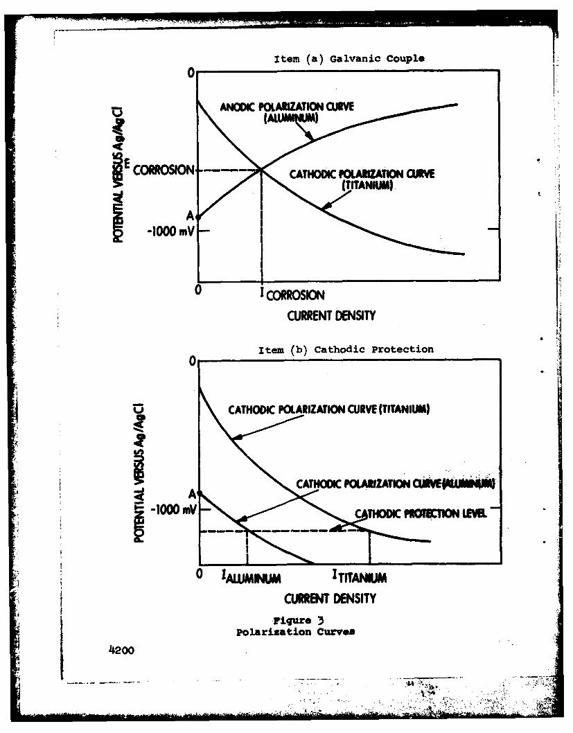
As a result of electron exchanges at the interfaces, themetal potentials, as measured against a standard reference cell,will change from the original open-circuit potentials. Thischange in potential, due to the current flow to or from thesurface, is called polarization. Potential can be plottedagainst current to give a polarization curve. The shape ofpolarization curves can be influenced by environmental conditions,such as velocity and temperature. An example of polarizationcurves, shown in item (a) of figure 3, illustrates the type ofbehavior which occurs in galvanic coupling of dissimilar metals.The potential of a metal before any polarization is produced,called the open-circuit potential, occurs on its polarizationcurve near the y axis. The potentials of the anode and thecathode shift as the current is increased. The intersection ofthese curves defines the corrosion current, Icorrosion' and thepotential of the galvanic couple,or mixed potential, Ecorrosion.To prevent accelerated corrosion of the anode, it is necessaryto shift the potential of the couple below the open-circuitpotential of the anode (point A) which, in the case of an
1200 2
aluminum-titanium couple, would have to be less than -1000 mV.*Two approaches can be used to prevent galvanic corrosion atthe anode. One is to isolate it electrically from the cathode.This approach is usually impractical on complex structures.The second is to apply cathodic protection to complex structures,an expedient which shifts the mixed potential of the couplebelow the open-circuit value of the more electronegative material.
Item (b) of figure 3 illustrates the cathodic polarizationcurves of the two coupled metals when cathodic protection ispresent. The intersection of each curve with the constant-potential cathodic protection line determines the current nec-essary to polarize that material to the specified protectivelevel. Notice that the more noble material, titanium, requiresmore current than the less noble material, aluminum, to polarizeit to the appropriate potential. Also, as the protection poten-tial level becomes more negative, the current needed to polarizeeither material to that potential increases.
Both active and passive methods are used to apply cathodicprotection. The passive method consists of adding a third,highly electronegative,material to the system. In the exampleof an aluminum-titanium couple, this would have to be a materialthat is more electronegative than aluminum, such as zinc. Thismaterial will then corrode in preference to the aluminum. Sinceit sacrifices itself to prevent corrosion of the other materials,this third material is called a sacrificial anode.
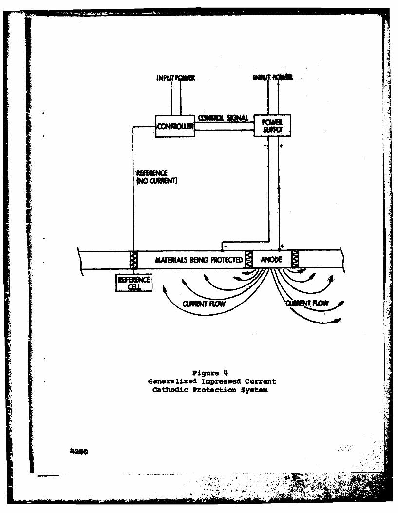
The active method to lower the potential of a couple iscalled ICCP. In this method, the sacrificial anode is replacedby an anode of an essentially inert material, such as platinum,to which an external voltage is applied. The basic componentsof an ICCP system are illustrated in figure 4. Voltage,supplied by a power supply to the anode, is regulated by thecontroller in order to hold the materials being protected at aconstant potential. The potential difference between the refer-ence cell and the metal near the cell is fed back to the con-troller. The current output required from the system to maintaina constant potential at the reference cell will vary with theconditions at the metal surface. Sea-water velocity is prob-
* ably the most important variable, and generally, greater cur-rents will be required at higher velocities.
*Abbreviations used in this text are from the GPO Style Manual,* 1973, unless otherwise noted.
*4200 3

Before describing componants that would be used for anICCP system of a surface-effect ship, it is necessary to pointout one special problem encountered with such systems onaluminum-hulled vessels. While some protection of an aluminumhull is required because of the galvanic coupling with noblemetal appendages on the surface-effect ship, the problem ofoverprotection of aluminum must also be recognized. Asindicated in figure 2, hydroxyl ions are generated at thecathode of a galvanic couple. Similarly, an alkaline solutioncan be generated at the surface of cathodically protectedmetals. Under conditions of overprotection, where the hullpotential is driven too far negative, an excess of these hydroxylions will be generated, causing a condition of local alkalinityat the metal/sea-water interface. This highly alkaline environ-ment will rapidly attack aluminum and other amphoteric* mate-rials, causing a condition called overprotection corrosion. Asteel-hulled ship would not corrode under similar conditionsbecause iron is not an amphoteric meta. Since overprotectioncorrosion of aluminum can be very rapid, it is necessary tominimize the possibility of it occurring by care in the designof the system and selection of the components.
The basic components of an ICCP system for surface-effectships are the power supplies, controllers, power generationequipment, the hull-mounted anodes surrounded by dielectricshields, and the hull-mounted reference cells. ICCP systemsmu& empLoy dielectric shields to lower the current densitydelivered to the aluminum near the anode. The function cO theshields will be further explained later in this section.
There are two main types of power supplies, saturablereactor (SR) and silicon-controlled rectifier (SCR). TheSR type is most widely used for shipboard applications due toits availability and functional experience. This is the onlytype of unit readily available from commercial sources. However,it is bulky and heavy due to the large transformers used in thecircuitry. Also, due to the operational characteristics of anSR, there is a minimum current which the power supply candeliver and a relatively long reaction time compared to SCRunits. Extra circuitry can be installed to bypass this minimumcurrent, but the equipment adds weight and requires more space.Unless careful selection is employed, this minimum current may
*Amphoteric capable of reacting with either acids or bases.
4200 '4
still exceed ship demands under certain operational conditions.Overprctertion corrosion or excessive degradation of coatingsdue to high cathodic potentials could occur under thesecircumstances.
The second type of powei supply is the SCR, These uritsare smaller and lighter in weight and have no minimum currentoutput; however, they are not standard commercial productsand experience with their use is limited. Due to the rapidrespoase of the SCR, interrupter reference measurement car beemploled. In this potential measurement system, the anode cur-rent is momentarily cut off during the time that the hullpotential measurements are made. Thus, the anode -urrent willnot influence the accuracy of the measurement, because themeasurement time is so brief that te hull potential does nothave an opportunity to return to the unprotected -yalue. SCRunits are sensitive tn input power transients, which could occuron marine craft, and special overload protection must be employedto .prevent damage to the solid-itate components in the powersupply.
The output from either type ICCP system will be a rectifieda-c signal which will have ripple, the amount depending on howmuch attenuation has been incorporated into the design ot theunit. Other instruments on the craft, especially those inter-facing with the sea water, may be affected by this ripple,possibly causing erroneous readings. Certain a-c ripple fre-quencies, primarily from power generation harmonics, or inducedelectromagnetic interference generated by oth _r on board
electriral equipment, may Alo be transmitted to the sea waterby the ICCP system. Due to the more rapid response of the SCPunit, it may be more likely tc transfer these types of signals tothe sea water. Troublesome ripple frequencies must therefore befiltered out by the use of extensive filtering circuitry oravoided by appropriate shielding.
The controller determines the variation between the preset: protection potential and the actual hull potential at the refer-
ence cell, and generates a control voltage which signals thepower supply to adjust the anode current iccordinglf. Con-trollers are available with dual outputs to control two powersupplies at once, or with sensitivity adjustments, meters, etc.Many units can be modified to allow the use of a second referenceelectrode at the edge of the shield which will reduce powersupply output if overprotection conditions are reached at thislocation.
1 J 200 5j
J-sc
Supplementary power generation equipment may be necessaryif craft power is not available. This additional equipment willadd weight, as well as operating, maintenance, and fuel supplyproblems to the craft. Generally, it is better to use the powergeneration equipment already installed in the craft, if possible.or'to increase the capacity of this equipment where feasible tohandle the extra load.
The reference cell most frequently used for marine craftis the Ag/AgCl type, due to its durability and adaptability toconstant immersion conditions. This cell consists of silverscreen or wire covered with partially reduced silver chlorideand given complex stabilizing treatments. This screen is thenplaced in a nonconducting container with holes for water access,and the assembly is flush-mounted against the hull at theposition where the hull potential can be best measured.Although only one reference cell is required for system control,more are usually employed. The others are used as spares or asa means of checking on proper operation of the cell controllingthe system.
Current-delivering anodes are generally made of platinum-coated titanium or platinum-coated tantalum. Platinum, whenmade the anode of such a system, instead of releasing ions intothe sea water will generate gases, such as chlorine, at itssurface. Platinum-coated tantalum is normally preferred due tothe resistance of tantalum to high voltages, permitting highercurrent densities at the anode. Two main types of hull-mountedanodes are commercially available. Round anodes are usuallyabout 1 foot in diameter and flush-mounted against the hull.Strip anodes are generally available in 4- and 8-foot lengthsand are less than 1-inch thick. They are usually surface mountedon the hull.
Surrounding each anode, for a distance of several feet, isa thick, waterproof, nonconductive material called the dielectricshield. In the absence of this shield, the anode current wouldfollow the path of least resistance to the hull and would there-fore be concentrated in the area near the anode. This highcurrent density would generate an alkaline condition at the hullsurface in this area, causing, in turn, overprotection corrosion.The shield increases the separation of anode and wetted hull.The resultant voltage drop through the water widely distributesthe current and lowers the apparent anode potential at the hullbeyond the shield. Since the current density is a function of1/rn , where r is the distance from the anode and n is a geo-metrically dependent constant greater than 1, then the magnitude
4200 6

of the voltage gradient will be large near the anode and will con-stantly decrease am distance from the anode increases. The exactvalues will depend on the cathode sturface geometry, seawaterresistance, etc.
There are many types of dielectric shield materials, in-cluding epoxy mastics, coal-tar epoxy resins, polyurethane coat-ings, and rubber coatings. Integrity of the shields is critical,as even a small defect could lead to catastrophic overprotectioncorrosion of the aluminum beneath. Shield materials should havegood adhesion, som.e resistance to mechanical damage, and theability to withstand high anode potentials.
An alternate method for reducing overprotection near the anodeis to mount the anode in a remote location, away from the aluminumhull. This approach, which eliminates the need for a dielectricshield, is discussed in appendix B.
METHODOLOGY - APPROACH TO DESIGN
The design of an ICCP system for a aurface,-effect ship canbe accomplished in the following steps:
o Determination of current required, maximum andminimum.
o Selection of power supply and controller.
a Determination of number, size, type, and location ofan s * Determination of type and configuration of dielectric
shield.
* Determination of type and location of reference cells.
o Alteration of ICCP system design to increase itscompatibility with craft design.
To determine the current requirements for the system, aprotection potential must first be chosen which will minimise
* galvanic effects of the appendage materials on the hull. Thelevel chosen should be slightly more electronegative than theopen-circuit potential of the aluminum hull. However, theeffects of this potential on other materials in the systemshould be considered. For instance, 17-4 PH steel in same heattreatments experiences hydrogen embrittlement when coupled toaluminum, due to the generation of hydrogen at the cathodic
4200 7
(17-4 PH) surface.' When protection is applied at a potentialmore electronegative than the mixed potential of aluminumcoupled to 17-4 PH, excess hydrogen is produced, and thetendency for hydrogen embrittlement is intensified. After
selecting the potential level, the approximate effective gal-vanic area of each material should be calculated under variousoperational conditions. Besides geometrical considerations,effective galvanic area is a function of the hull and appendagecoatings used, the estimated rate of degradation of thesecoatings, and the frequency of coating repair. Also, if electri-cal isolation occurs, such as in certain propeller systems, theeffective area must be reduced accordingly. It should be notedthat the effective galvanic area of internal surfaces of pipingmay only extend several pipe diameters from the end of the pipe,due to IR drop.
The current demanded from the cathodic-protection system byeach material is the product of its bare wetted area and thecurrent density necessary to polarize it to the selected pro-tection potential under the specific operational conditionsinvolved. The total current demanded from the system is then
the sum of the currents demanded by each material. This totalcurrent should be calculated for various operational modes,including dockside, cushionborne at low velocities, and cushion-borne at high velocities. Values of minimum and maximum currentsrequired from the system can thereby be determined.
Once these currents are known, a power supply and controllercan be chosen. The power supply should be capable of convertingships' power into usable power for the anodes. It should havethe capacity to supply the maximum current needed over longperiods of time. It should also be able to limit its output toless than the minimum current previously calculated. The con-troller unit should be capable of controlling power supply out-put over its full range, with appropriate sensitivity to avoidslow reaction or overcompensation. A sensitivity adjustment isdesirable.
Another necessary feature for any controller unit is fail-safe design, which will cause the controller output to reduceto the minimum value in case of system malfunction. Thisimportant feature can minimize the possibility of overprotectioncorrosion if a malfunction occurs which would otherwise drivethe anode current above the level which causes overprotection,
iJacobson, P. S., and D. D. Miller, "Preliminary Evaluation ofHydrofoil Base Metals and coating Systems," The Boeing Co.,Seattle, Wash. (1973)
4200 8!i "

such as open circuited or shorted anode or reference cell wires.Additional considerations in the selection of these two units in-clude physical size and weights relative to ultimate location inthe craft, ease of monitoring system function, reliability, andoverhaul requirements. In addition, the controller must be stableand able to withstand marine atmospheres, vibration, and shock.
Shape and placement of anodes is critical in the design of animpressed-current system. Generally, anodes should be more can-centrated in the vicinity of dissimilar metal appendages, sincethese will absorb a large portion of the anode current. Theyshould be totally submerged under maximum velocity cushionborneoperation to maximize their current-delivering capability. Onsurface-effect ships, limited submerged areas in the cushionbornemode place special requirements and limitations on the size,shape, and type of anodes needed. Other than this, anode place-,ment and shape should be chosen to distribute the anode currentevenly over the wetted surface areas. Due to the high speed ofsurface-effect ships, the anodes may need to be flush-mounted orfaired into the hull. There is a possibility that no coaerciallyproduced unit will be satisfactory, and a special design willhave to be used. Once the specific anode type is selected, itsmaximum current rating should be divided into the maximum control-ler output current to determine the number of anodes necessary.These should then be distributed around the hull according to thepreviously mentioned considerations. Placement in an unsymmetri-cal situation, such as near the water surface or next to a corner,should be avoided whenever possible to permit even distributionof the anode current. Consideration should also be given toremote mounting of the anodes, as discussed in Appendix B.
The dielectric shield is the weakest link in the impressed-current system. As previously explained, this is particularlycritical on an aluminum hull. Proper selection and design of the
shields are necessary to prevent severe overprotection corrosion.The shield material selected must be able to withstand high ve-locity effects, including cavitation and erosion, and high anodevoltages, without exhibiting any tendency towards disattachment
*or blistering. Of course, if the remote anode concept is uti-lized, the need for a dielectric shield is eliminated.
Design of the shield is as critical as selection of thematerial of which it is constructed. The shield is applied tothe hull around the anode for a specified minimum distancewhich is dependent on maximum anode current. If noble metalsare located near the anode, the shield should be slightly ex-tended in their direction since the presence of these materialswill tend to distort the potential profile around the anode due
4.2oo 9
to the large amount of current these materials conhume. Coatedappendages will distort the field less than uncoated appendages.The best available conservative values for minimum dielectricshield distance from the anode were established for conventionalcraft, 7 feet for a 100-ampere anode and 11 feet for a 200-ampere anode.
Although a single reference cell is used to control the
normal operation of the impressed-current system, usually aminimum of two are installed. The second is used as a spare 4and to check the stability of the controlling reference cell.Reliability of these cells is important. On craft with properlydesigned dielectric shields, reference cell failure may leadonly to wasteful current excesses, but reference cell malfunctionmay increase the degree of overprotection corrosion experiencedon an aluminum-hulled craft with shield deficiencies. Placementof the reference cells is also critical. Generally, they shouldbe mounted well away from the anodes but not in areas that arecompletely sheltered from the anode current, for example, nearcorners or in areas near significant amounts of dissimilarmetals, such as propellers. The general intent is to place thereference cells in an area well representative of overall hullpotential. Additional cells may be mounted in areas of concern,for instance, near appendages, provided that they are not usedto control the normal operation of the system but are for infor-mation and safety only. One such reference cell should beplaced at the edge of the dielectric shield. This cell couldact as a safety device to provide the controller with informationconcerning when overprotection conditions are reached at theshield edge, so that the anode current can be reduced accord-ingly.
There is essentially only one type of reference cellpresently used for shipboard systems, Ag/AgCl. These cells havedemonstrated their reliability, and therefore, there is presentlyno reason for using any other type. Different mounting config-urations are available. The optimum configuration for an SEScan be selected from knowing the sea-water flow characteristicsand hull structure in the area in which the cell will be.mounted. Cavitation must be avoided at the reference cell/sea-water interface, as the trapped air may eliminate the sea-water path necessary between the reference cell and the adjacenthull.
once the system components have been selected and locations. determined, many problems will appear which must be resolved
before installation. Structural modifications to the hull may
L,4200 10
., :. .

have to be performed in order to accommodate hull-mounted equip-ment. Space for hull-mounted and on-board equipment may be re-stricted. but adequate access space must still be provided, asthe equipment must be monitored. Anode cable lengths should be
"kept to a minimum, and special procedures must be followed if thecables run through fuel tanks, such as shown in NAVSEC 9000-S6202-73980, section 2, sheet 155. If boat power is not avail-able to drive the power supply, then the addition of an auxil-iary generator will be necessary. High sea-water velocities maycause cavitation or erosion problems on hull-mounted equipment.In short, all aspects of the system must be considered before
*l final equipment selection and installation.
METHODOLOGY - APPLICATION TO SES 100B
To apply the methodology outlined in the previous section toa 100-ton surface-effect ship (SES 100B), .a series of laboratoryexposures were conducted to establish the protection potentiallevel and current requirements. These laboratory tests are de-
tailed in appendix A.
Protection current and open-circuit potential data both leadto the conclusion that the protection potential at which the ICCPsystem operates should be -1150 my. Protection current data in
2 ~ appendix A (table 5-A) show a protection value of 47% at the-1100 mV level in the last line and 100% at all other -1100 mVtests. This implies that a potential slightly more electronega-tive than this, i.e., -1150 mv, should produce 100% protectioniii :.:at all velocities and temperatures.
The control potential should be equal to, but not exceed, themost electronegative open-circuit potential expected of the alumi-num hull. Although it is commonplace on steel vessels to suppressthe steel corrosion by using potentials 50 to 100 mV more negativethan the open-circuit potential, this practice is not recommendedfor aluminum-hulled craft, since aluminum cannot be cathodicallyprotected to reduce its corrosion rate below the unprotectedlevels.* Data in table 5-A indicate that the corrosion rate ofcathodically protected aluminum, at levels to -1150 iWe is atleast as great as when unprotected. In addition, the arbitraryuse of a -50 to -100 mV shift in control potential might increasethe possibility of generating overprotection potentials at thehull, or of causing coating degradation associated with high cur-rent densities, especially on the noble metal appendages. Thecontrol potential should therefore be equal to the most electro-negative open-circuit potential expected of the aluminum hull.
*Groot, C., "Cathodic Protection of Aluminum," Materials Pro-
tection, (Nov 1964).
4200 11
The expected potential range of the hull can be found byconsulting data in table I-A of appendix A. Of the 161 aluminumopen-circuit potential data points from which the average valueswere calculated, 9.3% were more electronegative than -1100 MVand 0.6% (one value, -1164 mV) were more electronegative than-1150 mV. Therefore, a choice of -1150 MV for the controlpotential appears to be reasonable.
Based on the above current and potential data, a cathodic-protection control potential of -1150 MV versus Ag/AgC1 isrecommended for surface-effact ships. Current data at thiscontrol potential are not available for design purposes; however,the data in table 4-A of appendix A at -1100 UV can be used asa reasonable approximation for the following reasons:
9 Power supply current rating will probably exceedcraft requirements due to a limited selection of availableequipment.
e Actual current densities will probably be less tha~nthe maximums chosen in the design.
0 Small specimens used for design may have greaterpotential and current fluctuations with greater resultantmaximum values than large structures, such as the aluminumhull, due to an averaging effect of large areas.
* The critical estimate of 10% coating defects usedlater in this section may be larger than is actually present onthe craft, especially due to the probable frequent maintenancerequired of an experimental craft.
* Areas under the dielectric shield coating should beessentially free of defects. The exposed area calculations forthe hull do not deduct for the area of the defects which wouldbe in the dielectric shield area in the absence of the shield.
The maximum and average current densities at -1100 MV aretherefore to be used in the ICCP system design. These values,from appendix A. are summarized in table 1.
4200 12
7- A.
TABLE 1 - CURRENT DENSITIES -
(AMPERES/FT') AT -1100 MV
trVelocity, knMaterial . 0 " 28 55 77
17-4 PH Stainless SteelMaximum 0.14 4.91 5.73 5.97Average 0.02 3.06 4.58 4.90
Ti-6A1-4vMaximum 0.09 3.04 4.85 1.83Average 0.02 1.77 3-74 0.88
5456 AluminumMaximum o.oo10 ) 0.58 1.19 0.23Average 0.007(l) 0.27 0.67 0.09
)Data from previous tests on hydrofoil materials.
Table 2 presents the calculations of wetted areas for thevarious components in the SES 100B at different keel depths.The area of each section was found by rough geometrical approx-imation taken directly from the craft blueprints. All areaswere considered to be coated except the propeller and fairwater.A selection of 10% for the area of coating defects was made onthe basis of craft observations and from a need to provide amargin of safety. The selection of a defect area is importantto final system design and should be made after consideringcoating deterioration rates from craft service records, coatingtest data, and length of time between overhauls for coatingrepair. If the operational pattern of the craft permits fre-quent coating repair, then the 10% defect area can be reduced,lowering the current requirements.
Also of importance is the degree of electrical isolationbetween the propellers and the hull. As the propeller is notcoated, it absorbs a great deal of current. If electrical iso-lation occurs, the maximum current needed from the system may bereduced. If tests verify that lubrication in the transmissiQngears electrically isolates the propellers while under way, thecathodic-protection system will not be required to delivercurrent to them, reducing the maximum current requirements ofthe system. Calculated wetted areas in table 2 are multiplied bythe appropriate current densities of table 1 in order to obtaini total current requirements under various operational conitions. !
The results are presented in table 3. The maximum controllercurrent requirement for any operational mode, which appears inthe next to the last column, is 378.5 amperes.
.42oo 13
- - , . . .• , " , ..

S 0 t- W cyf. 0 J
U%O 0 ^or c
D 0 P- OD A *Y If\
34eC' .4 cO0 -w4O 0 C J 0 .1 % 0% t t M D(
cu cu~o' 0 O N of0a
0* OD 0 0 00 Co ojOC 100. o ; "v Lot -A U\
0.00 %0%0 0000 aicuC%0''0
Ono oojm ooo\o0 AF cu 0%w'
-4 if .a .1
CY r4
b%0 4 Cull 4N I % "-4 4 .4-4
0Ci -it U 0 A .-4'.OI.\94
'A\ 4 404 %*
.4 .4.M
42C* 144.OI
Wr
Go CY 0N -1. U a
CA Cuj -. U' ' -
Ca. -Y I,- _ ____ __ K\____ __ O_
14 1 uU
14
~ a~ -~'O 0 .O O C'O j .40 at~4-4 U
-14 > 14 .. -. 4
'o -
04 .44 NU' oIL ' . 0 p'0 t.-0 ^OO
u 4c o%"~ ^M^' N4U 44it -
r. r
N
14
45% COt 4 Ot 45 CO~ t-~ CU(U0. *U. E;oA 6Az; L . .4j ; 64 U ;
Ul 0 909 - l % 0 0 ",
40 _ _ _ _ _ __ _ _ _ _
r ..
0 c \0..4 .4
4&2oo 15

If the hull and appendage coatings have no defects, the ex-posed area of aluminum (from table 2) will be 0, titanium willbe 33 fta (propellers), and stainless steels will be 19.4 ft8(propeller hubs and fairwaters). At V - 0, the average currentdensities for titanium and stainless steels are 0.02 amperes/ftgiving an absolute minimum current rating of 0.66 + 0.39 - 1.05amperes. The cathodic protection system must be controllable atthis low current level, to minimize the possibility of over-protection of the aluminum.
On the basis of the calculated current requirements, a con-troller unit can be selected. The Engelhard model 50011-2saturable reactor power supply, which supplies up to 450 amperes,best suits the requirements. To lower the minimum currentproduced by this supply, special circuitry is needed. Theminimum can be dropped from 45 to 22 amperes by the manufacturerif the power supply is specified with an "L" suffix. The re-maining 22 amperes must be bypassed by special circuitry pro-vided by the manufacturer. This can be accomplished, but itmay require an additional cabinet to house the equipment.
Engelhard controller model 36600 can be used in conjunctionwith this power supply. Filtering on this supply should bespecified to provide an a-c ripple energy less than 1% of thetotal output, to minimize ICCP system electromagnetic interfer-ence with other craft systems. This unit will also have to bemodified to provide an anode current limitation based oninformation provided by the reference cell at the edge of thedielectric shield.
At present, craft power is not available for these units.A separate power generator must therefore be supplied, orcraft generation equipment increased to handle the added load.The generator must be capable of supplying 30 amperes, 440 volts,60 Hz, 3-phase current (up to 10 kVA) for the power supply,and 10 amperes, 110 volts, 60-Rz, single phase current (up to0.5 kVA) for the controller unit.
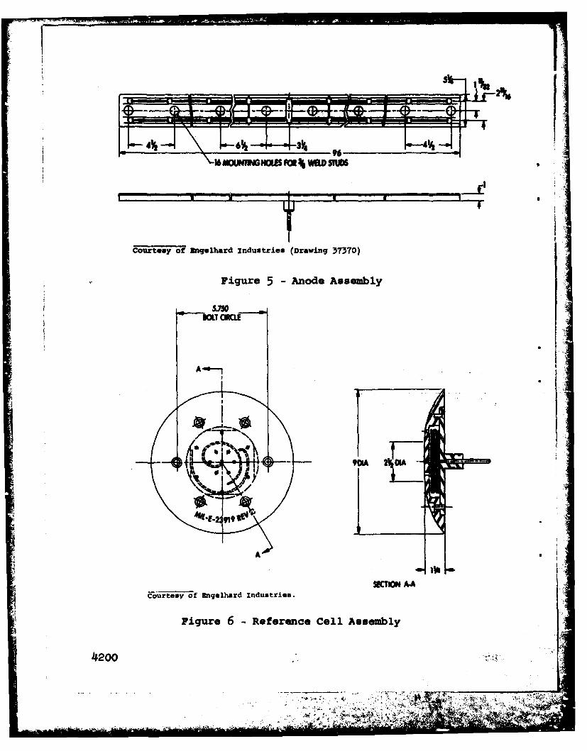
Anode number, type, and location can now be selected. Anappropriate choice is two 200-aeere anodes located aft on theport and starboard sidewalls, since the dissimilar metalappendages are all located aft. As the craft draws only 6inches at maximum velocity, selection of the shape and 1oationof anodes is simplified. Strip anodes must be used, such asEngemard model 37370 (figure 5) or Lockheed 96-inch "shipboatd
.I200 16

I strip anode," and the location must be as close to the keel aspossible to keep the anodes submerged. This can be accomplishedonly by affixing the anode to the lower slanted section of thekeel. The exact location of the anodes will depend on struc-tural considerations.
As no potential profiles of impressed current anodesoperating at full current output are available, the size of thedielectric shield must be determined from the manufacturers'recommendations and some reasonable hypotheses. The 200-ampereanodes suggested for use on the SES 100B have a recommendedminimum distance of 11 feet in all directions from the edge ofthe anode. This distance appears to be somewhat excessive sincethe majority of the current will be delivered to the appendagesnear the anodes, within the shield. Table 3 shows that themaximum current delivered to aluminum components in any opera-tional mode is 92.0 amperes or about 50 amperes per anode. The
I actual figure should be somewhat less than this, due to thecoverage of some aluminum by the "defect-free" dielectric shieldmaterial. Since the recommended minimum dielectric shieldcoating distance around an 8-foot anode delivering 100 amperesto a steel hull is 4 feet, a minimum distance of 4 feet should beample for about half of this current delivered to an aluminumhull. A great deal of current should flow aft to the propellersand gearboxes. Therefore, it is recommended that the finalshield start at least 4 feet forward of the anode and extend tothe stern of the craft, with a minimum height of 4 feet abovethe keel.
To date, three materials appear to be reliable for dielec-tric shield applications. Material 1 is troweled on, and ade-quate smoothness to prevent cavitation may be difficult to ob-tain. Also, being an epoxy, it may experience brittle behaviorif significant sidewall flexing is present. Material 2 wasrecently discovered to contain a carcinogenic solvent and there-
tfore requires extreme care in application to meet occupational10- health standards. Although reformulation of the material is
possible, retesting would have to be performed to confirm thesimilarity of properties to the original material. Material 3is tough; and contains an antifoulant. The third is thereforerecommended as the best state-of-the-art material to date fordielectric shields on surface-effect ships.
Type and location of reference cells must next be determime.Presently only one type of reference cell (figure 6) is approvedfor naval craft. This is a 9-inch (23 cm) diameter faired disk.This cell has proved to be stable and at present has the best
4200 17

streamlining of any cell commercially produced for large craft.
One of these cells could be mounted in the lower slanted sectionof each sidewall a quarter of the boat length aft of the bow fornormal control purposes, and a second cell mounted in each side-wall just outside the dielectric shield to monitor for overpro-tection. A third pair of cells should be mounted near the sternto check the system's effectiveness in polarizing the noble metalappendages. The third pair of cells is needed 4- obtain addi-tional potential data for this experimental system, although notactually required for system control. Total weight of the systemas described is as follows:
Pound'sPower Generation Equipment - 1000Pc',er Supply 660Controller 47Anodes 120Dielectric Shields 3 300Reference Cells 90other Equipment -, 200Total System Weight 2417
The physical size of the units can be found in the next sectionof this report. The size and weight of the extra cabinet tocontain current bypass circuitry is unknown, but the size shouldnot exceed that of the power supply cabinet.
AVAILABLE COMMERCIAL UNITS
There are two major producers of ICCP system components formarine rr ft, Engelhard Industries, Division of EngelhardMinerals nd Chemicals Corporation, and Lockheed Marine Services.Lockheed specializes in custom-designed and custom-built equip-ment, except for a small line of current-delivering anodes.Therefore, Engelhard is the main source for standard commercialpower supplies, controllers, and reference cells. Several othersuppliers produce power supply units.
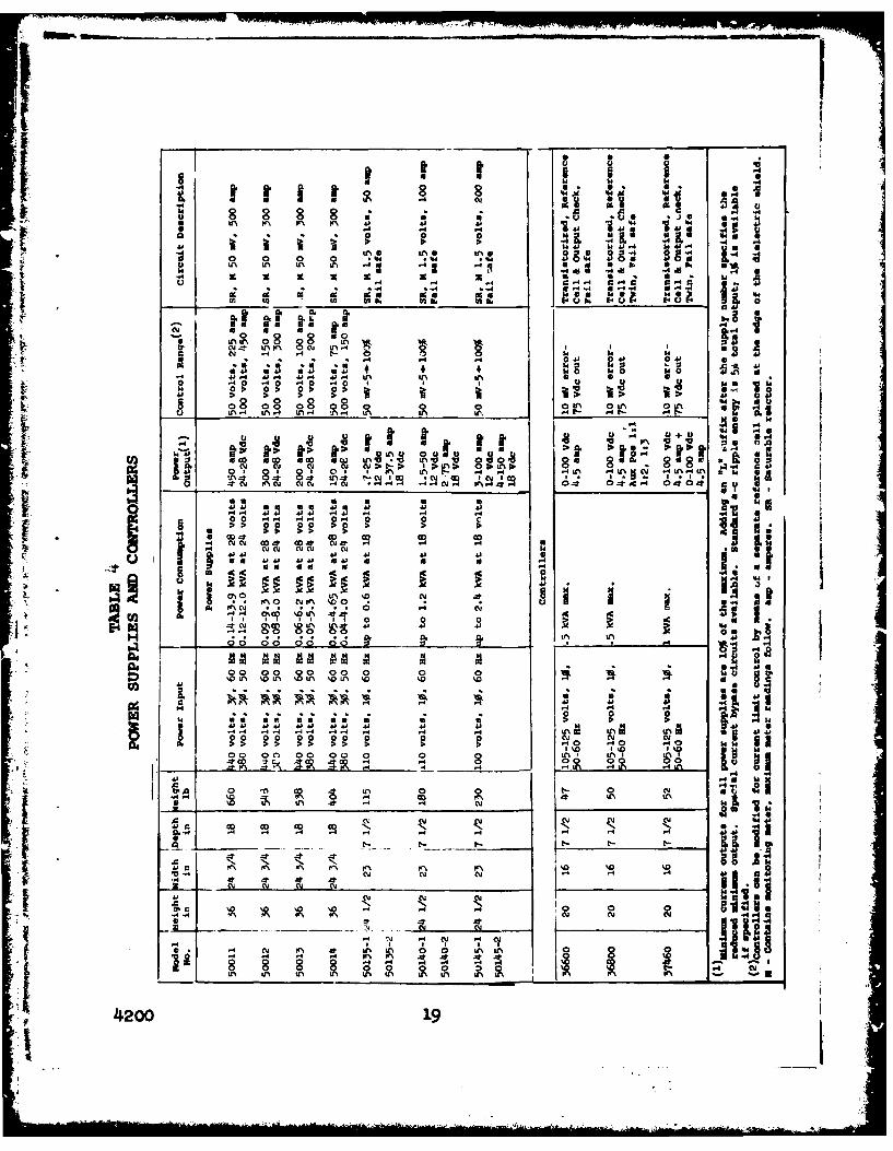
Table 4 gives a list of power supplies and controllersavailable for large craft (greater than 100 amperes) and rele-vant data needed for component selection. All units are manu-factured by Engelhard. Notice that all of the commercially avail-able units are of the SR design, and that none of the units isdesigned to input 400-Hz current, which is attractive for use onsurface-effect ships.
i 4200 18 i_1
0k -0 8 8
0. 0. 0 0 0 6. we
(a . . . ca 144 toi skrjD.I 9a
0~ JZ 0 FN 0 N ~ .4 gc 2u *.4 4
41 14 4) 01 14S VU 14
U)b in& Ir. 01. k
'~w 6.4. 0+. a. 0 A
4-(' 84 8 0. ~ 1*L 0~ 88 48 8I~~ ~ if ;fsot i ;C. U.. >V+TU
C.~~~ 064L%
-a a 9
4)va a a a 41 14 4lo-44 44 4J4 44 0 44 V ' 4 4 .4 .440 0 .I.
0,N -Cl -- Is40' ~C *u 44u 444 64 4I
0 %0- CY -t
- 0 00 00 003 V
-4 04 Uof 4A
* . - . . * *q 0 0 0a.~c ma mua a u12
". 00 0 0
00 00 00 0
A __
4**1111
4200 19f 00 L
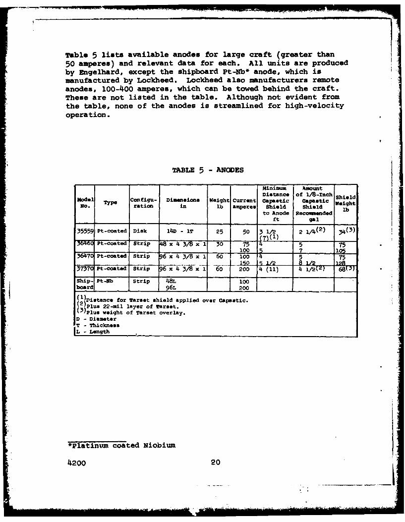
Table 5 lists available anodes for large craft (greater than50 amperes) and relevant data for each. All units are producedby Engelhard, except the shipboard Pt-Nb* anode, which ismanufactured by Lockheed. Lockheed also manufacturers remoteanodes, 100-400 amperes, which can be towed behind the craft.These are not listed in the table. Although not evident fromthe table, none of the anodes is streamlined for high-velocityoperation.
TABLE 5 - ANODES
Minimum i AmountNodel Configu- DiVsiona Weight Current Distance of l/8-Inch Shieldoe Type fC nt Capastic Capastic WeightNo. ration in lb amperes Shield Shield
to Anode Recommendedft gal
35559 Pt-coated Disk 1/D - IT 25 50 3 1/2 2 i/4(2) &(3)
35460 Pt-coated Strip 48-x 4 3/8 x 1 30 75 5 75 -)7100 7 105
670 Pt-coated Strip 96 x 4 3/8 Xl 60 100 4 5 75...... 1 9 1/2 8 I/Z 10A
37370 Pt-coated Strip 6 x 4 3/8 x 1 60 200 4 (11) 4 -/27) 68(3)
Ship- Pt-Nb Strip 48L 100board 1 96L 200
1)Distance for Tarset shield applied over Capastic.2 )Plus 22-mil layer of Tarset.(3 )Plus weight of Tarset overlay.D - DiameterT - ThicknessL - Length
*platinum coated Niobium
4200 20
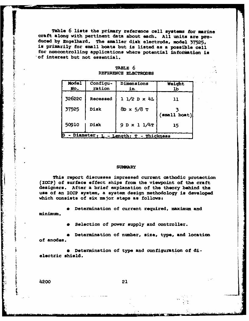
Table 6 lists the primary reference cell systems for marinecraft along with pertinent data about each. All units are pro-duced by Engelhard. The smaller disk electrode, model 37525,is primarily for small boats but is listed as a possible cellfor noncontrolling applications where potential information is'of interest but not essential.
T*~ 6REFERENCE ELECTRODES
Model Configu- Dimensions weight
No. ration in. lb
32622C Recessed 1 1/2 D x 4L 1137525 Disk 8D x 5/8 3
(small boat)
50910 Disk 9 D x 1 1/4T 15
- Diameter. - Length; T Thickness
SUNMARY
This report discusses impressed current cathodic protection(ICCP) of surface effect ships from the viewpoint of the craftdesigners. After a brief explanation of the theory behind theuse of an ICCP system, a system design methodology is developedwhich consists of six major steps as follows:
e Determination of current required, maximum andminimum.
& Selection of power supply and controller.
o Determination of number, size, type, and location~of anodes.
e Determination of type and configuration of di-
electric shield.
4I200 21I
It
" Determination of type and location of referencecells.
* Alteration of ZCCP system design to increase itscompatibility with craft design.
These steps are further broken down and subsequently illustratedby application to the SBS-1OOB. The major weak point of theICCP system, the dielectric shield, is discussed along with analternative approach, use of the remote anode concept. Failsafefeatures are emphasized.
The information presented in this report should aid thesurface-effect-ship designers in developing a "feel" for thecritical design parameters for impressed current cathodicprotection systems.
I
4200 22
"I _____x

Fiur I alancere
C~AMM M WAMW of Metals in Sea Water-3
aWUD%W (ACflWJ
1M CT"K ~*~ \ 7 V"L ,*W
A10
FiLgureGalvanic CQmplig
4l200 ,.
- Item (a) Galvanic couple
0 NDI POAIAIO V~
couo~oJ *----
-1000 M
0___ __________________
CURRENT DENSITY
0Item (b) Cathodic Protection
io CATHODIC POLARIZATION CURVE (TITANIUMJ)a
CATHODIC POLARIZATION CPMEWJINii3
0 'TITANIUM
CURRENT DENSITYriqure 3
Polarization Curves
4I200
SIMY Al
Figure 4iGeneralized Impreeced Current
Cathodic Protection System
42W4
xMOUTGO FM 41 WED SMW
Courtesy of Unqelhard industries (Drawing 377)
Figure 5 -Anode Assembly
£70
Couir-tesy of migehard industries.SK M A
Figure 6-Reference Cell Assembly
4200
"4N
APPENDIX A
LABORATORY INVESTIGATIONS
The purpose of the laboratory investigation was to obtainopen-curcuit potential and galvanic current data at high sea-watervelocities to apply to the design of an ICCP system for surface-effect craft.
ti APPARATUS
The high-velocity tests were conducted in a specially de-signed apparatus illustrated in figure 1-A. The specimen, 1 x4 x 3/16 inch, is supported by a slot in a hollow cylindricalnylon holder. Sea water is pumped across the specimen faces atvelocities up to 77 knots, controlled by different sized orifices~in the nozzle assembly. The leading edge of the specimen is
rounded to minimize turbulence. The specimen holder has plati-nized titanium anodes integrally mounted parallel to the water
flow opposite each specimen face. Small holes drilled in thenylon holder near the specimen faces are attached to tubing whichfeeds into a small container holding the Ag/AgCl reference cells,making a salt-bridge arrangement for impressed-current-systemcontrol.. The salt bridge permits sensing of metal potentialinformation from a remote location by establishing an isolated
- sea-water path between the reference cell and the.-cea of iterest.Electrical contact is made to the specimen by means of a contactI . screw of the same material, threaded through the specimen holder.
4MATERIALS
Materials tested were 5456-H117 aluminum for hull applica-tions, and 17-4PH stainless steel, titanium 6AI-4V, and Inconel625 for appendage applications. Nominal composition of thesealloys are:
5456 Aluminum - 5.25Mg, 0.Sn, 0.1Cr, Bal Alr 17-4PH Stainless Steel - 15.5-17.5Cr, 3.0-5.Oi, 3.0-5.1Cu,.15-.45Nb+Ta, Bal Fe
Titanium 6Al-4V - 5.75-6.75A1, 3.5-4.5v, Sal TiInconel 625 - 20.0-23.0Cr, 8.0-10.0o,
3.15-4.15 Nb+Ta, 5.0 max Fe,Bal Ni
4200 A-1
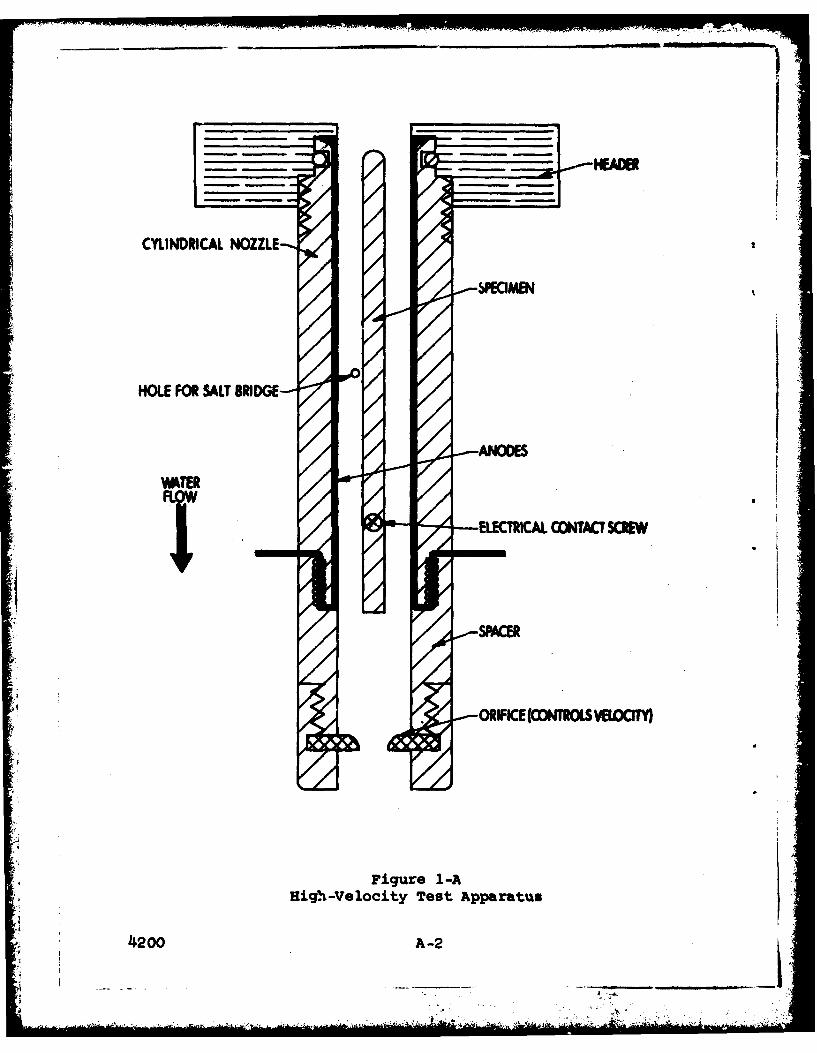
CYLINDRICAL NOZZLE
SWAAEN
HOLE FOR SALT BRIDGE-
,ooSPCE
Figure 1-AIHigh.-Velocity Test Apparatus
4I200 A-2
iINVESTIGATIO
Tests were conducted to determine the maximum open-circuitpotentials of the SES hull and appendage materials and themaximum protection current densities at various sea-water veloc-ities and protection potentials. The effect of water temperatureon the above parameters was also investigated. These tests wereconducted in the high-velocity apparatus at velocities of 28, 55,and 77 knots, and protection potential levels of -950, -1025 and-1100 MV. Test duration was 30 days.
Low-velocity tests (quiet sea water) were conducted todetermine the minimum protection current demanded by the SESappendage materials at various levels of cathodic protection.These studies were conducted by immersing 1/4-inch platespecimens, 3 x 4 inches, in natural sea water for 30 days at-950, -1025, and -1100 mV. Electrical contacts were isolated
f from the sea water by a silicone adhesive. Only the appendagematerials 17-4 PH stainless steel. titanium 6A1-4V, an-d IncOnel625 were tested, since the minimum current output of ati impressed,current system would be calculated on the assumption that nocoating defects are present. The only areas not coated arecertain appendages; therefore, assuming no coating defects-, theappendage materials are the only materials in contact with thesea water.
Thn final laboratory study was conducted to determine 'theresistance of various dielectric shield materials to high anodevoltages. Aluminum specimens, 4 inches square, were coated'withshield materials 2, 3, and 4, plus material 4 with anti-foulant. in addition, larger panels coated with Material 1 weretested. All'panels were affixed in a test apparatus whichallowed only the coated face to come in contact with the sea.water, and half of the coatings were pierced with a pinholeosized drill to simulate a coating flaw. The racks were immersed
* in natural sea water, and the panels held at -12 volts relativeto platinized titanium anodes mounted nearby. Total test timewas 6 months.
RESULTS AND DISCUSSION
Results of the high- and low-velocity tests appear in jtables 1-A to 4-A. Table 1-A presents open-ciruit data taiken.,.
before and after constant potential tests on 18 aluminum speci-mens at three velocities, and four aluminum and three appendagematerial control specimens exposed concurrent with constantpotential tests.
4200 A-3
- - - - - -
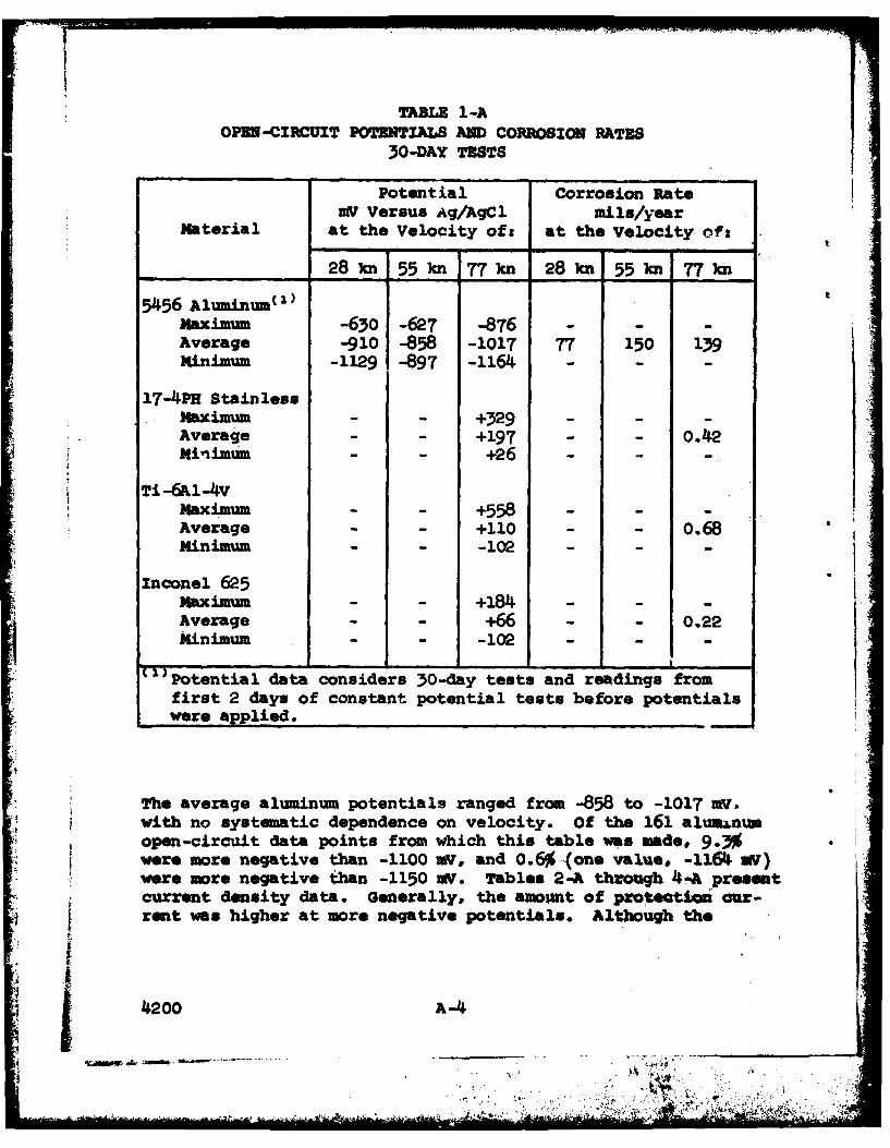
TABLE 1-AOPEN-CIRCUIT POTENTIALS AND CORROSION RATES
30-DAY TESTS
Potential Corrosion RateWV Versus Ag/AgC Mils/year
Material at the Velocity of: at the Velocity ofs
28 kn 55 kn 77kn 28 k 55 kn 77kn
5456 Aluminum(
Maximum -630 -627 -876 - -
Average -910 -858 -1017 77 150 139Minimum -1129 -897 -1164 - -
17-4PH StainlessMaximum - - +329 - --
Average - - +197 - - 0.Minimum - - +26 - --
'Ti-6Al-4VMaximum - - +558 - -
Average - - +110 - - 0.68Minimum - - -102 - -
Inconel 625Maximum - - +184 - --
Average - - +6- - 0.22Minimum - - -102 - --
Potential data considers 30-day tests and readings fromfirst 2 days of constant potential tests before potentialswere applied.
The average aluminum potentials ranged from -858 to -1017 m
with no systematic dependence on velocity. Of the 161 almnumopen-circuit data points from which this table was made, 9.3%were more negative than -1100 mV, and 0.6% (one value, -1164 at)were more negative than -1150 stV. Tables 2-A through 4-A preAKntcurrent density data. Generally, the amount of proteatoi our-rent was higher at more negative potentials. Although the
4200 A-4
- . . ..----------- -- *.***

Iiprotection current increased with increasing sea-water velocityup to 55 knots as expected, in many cases the current was lessat 77 knots than at 55 knots. Current requirements for polar-izing all of the appendage materials to the protection potentialfi generally differed by no more than a factor ,f two for a givenvelocity and potential, while the current requirements for thealuminum were usually more than an order of magnitude lower.
TABLE 2-ACONSTANT POTENTIAL
30-DAY TEST DATA (-950 XV)
Current Densities Corrosion Rateamperes/fta mi lu/year
Material at the Velocity of: at the Velocity oft
0 kn 28 kn 55 kn 77 kn 0 k 28 kn 55 kn 77_kn
5456 AluminumMaximum - 0.06 0.34 0.28 - . .Average - 0.0043 0.078 0.046 - 96 161 190Minimum - 0.0 0.0 0.0 - - -
17-4PH StainlessMaximum 0.073 2.31 4.22 4.38 - -
Average 0.023 1.30 2.98 3.20 nil 0.06 0.13 0.39Minimum 0.011 0.60 1.35 2.25 - -
Ti-6Al-4VMaximum 0.058 2.86 1.70 1.09 - - -
Average 0.025 1.14 1.67 0.77, nil 0.01 0.13 0.49Minimum 0.010 o.44 0.60 O.112 - -- -
Inconel 625Maximum 0.068 1.41 3.88 4.93 . . .. .Average 0.024 1.00 2.55 13.66 nil 0.08 'o0lli 0.46
minimum 0.O0 0.17 0.50 1.27 . . . .
i f
4200 A-5
AWM

Current Densities Corrosion Rateamperes/lft" sils/year
material at the Velocity oft at the Velocity Oft
0n 28 55 kn 77 01 28 kn55 77kn
5456 Aluuinu( )
MaxiMuM - 0.34 0.79 0.29 - - -
Average - 0.12 0.34 0.094 - 95 183 i8miniun - 0.0 0.028 0.0 - - - TABLE 3-A
17-i4 s±a Ze= CONSTANT POTENTIALmaxim= o.o94 3.24 5.29 6.75 30-DAY TEST DATAAverage 0.019 2.0 4.47 3.96 nil 0.02 0.11 0.23minimum o.o0 0.60 4.34 3.34 (-1025 v)
Maximm 0.063 3.28 3.72 3.72 - - -Average 0.019 2.o6 2.90 1.4I9 nil 0.05 0.07 o.42minimum 0.006 0.60 1.83 1.19
Inconel 625Maximum 0.194 1.85 4.14 6.29Average 0.026 1.01 3.13 4.53 nil 0.07 0.14 0.37Minimum 0.006 0.44 0.76 1.17 -
11 weighted average of values at -950 and -1050 MV.
Current Densities Corrosion Rateamperes/ft
a mila/year
Material at the velOcity oft at the Velocity of:
0 kn 28 )w 55 kn 77 k0 0 kn 28 551 w77 kn
5456 Aluminum" )Maximum - 0.58 1.19 0.23 - - - -
Average - 0.27 0.67 0.09 - 95 159 167TABLE M-Ainimum 0.7 0.20 0.0 - - - -
CONSTIMT POTENTIAL 17-4P StainloadzulvM 0.141 4.91 5.73 5.97 -. . . .
(-1100 XY) Kininu 0-004 1.73 1.57 3.18 -. . . .
ixaximu 0.089 3.o4 -.85 1.83 - - -Average 0.016 1.77 3.74 0.88 nil -.01 -.02 0.41Mnimum 0.003 o.48 2.69 o.40 . . . .
Xnconel 625lx.9 7.00 72.9 - - -
Average m0 1.08 1.44 3.51 nil 0.11 0.15 0.40
minimum 10.012 0.44 1.75 0.86
" 'verage of values at -1050 and -1150 V.
4200 A-6
' ' .
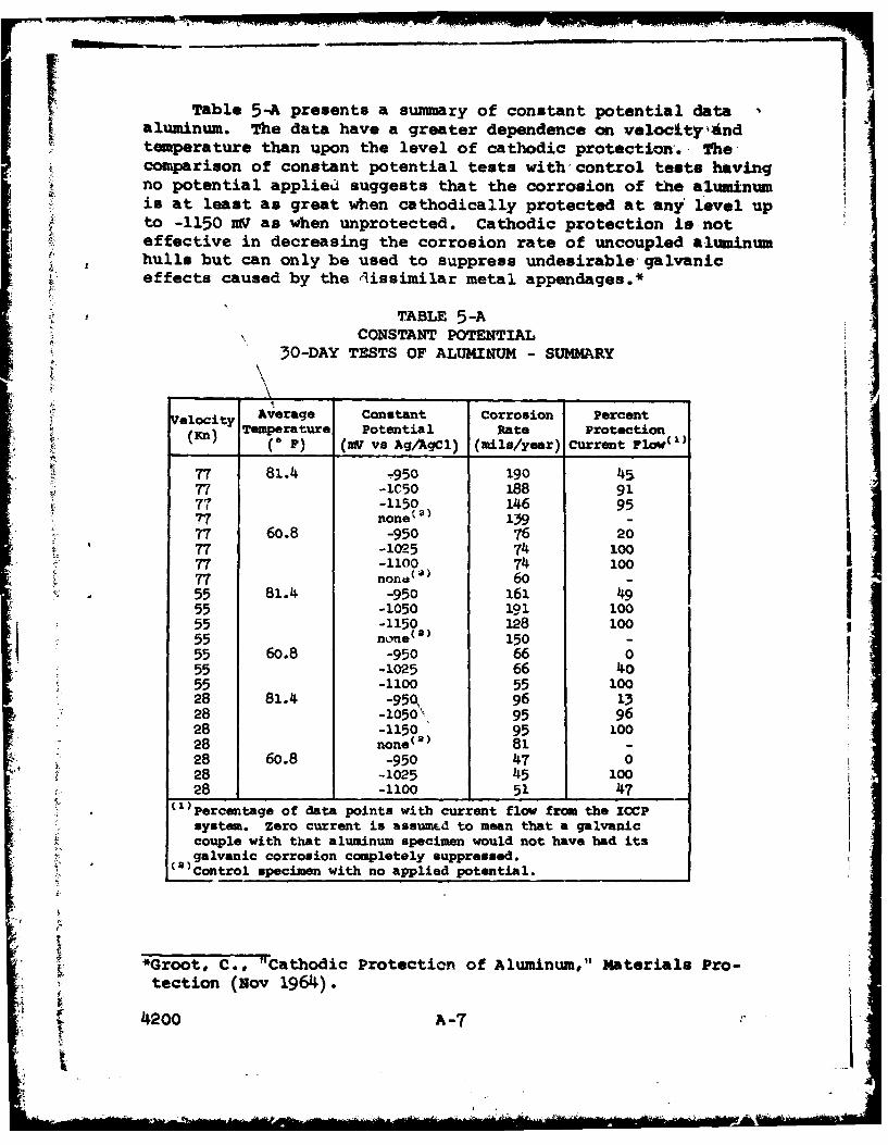
-IITable 5-A presents a summary of constant potential data
aluminum. The data have a greater dependence on velocity-Andtemperature than upon the level of cathodic protection. Thecomparison of constant potential tests with control tests havingno potential applied suggests that the corrosion of the aluminumis at least as great when cathodically protected at any level upto -1150 mV as when unprotected. Cathodic protection is noteffective in decreasing the corrosion rate of uncoupled aluminumhulls but can only be used to suppress undesirable galvaniceffects caused by the dissimilar metal appendages.*
TABLE 5-ACONSTANT POTENTIAL
30-DAY TESTS OF ALUMINUM - SUMMARY
Velocity Average Constant corrosion PercentTemperature Potential Rate Protection
___Kn (0 F) (MV vs AgAgCl) (mils/year) current Flow")a
77 81. -950 190 4577 -1C50 188 9177 -1150 146 9577 none t ) 139 -
77 60.8 -950 76 2077 -1025 74 100S77 -1100 74 10077 none ( a) 60 -55 81.4 -950 161 4955 -1050 191 10055 -1150 128 10055 none (a) 150 -55 60.8 -950 66 055 -1025 66 4055 -1100 55 10028 81.4 -950, 96 1328 -1050" 95 9628 -1150 95 10028 none(a) 81 -28 60.8 -950 47 028 -1025 45 10028 -1100 51 47
()Percentage of data points with current flow from the ICCPsystem. Zero current is assumepd to mean that a galvaniccouple with that aluminum specimen would not have had itsgalvanic corrosion completely suppressed.
(O)Control specimen with no applied potential.
t
*Groot, C., "Cathodic Protection of Aluminum," Materials Pro-tection. (Nov 1964).
4200 A-7
' " ..... " .... " '1 ' : .... .... :................... ... "" '; ......- '

Results of the dielectric shield tests are not yet complete.After 2 weeks in test, all dielectric shield materials are be-having similarly, with no evidence of blistering, peeling, ordisbonding of the coatings. Previous tests conducted on material1 at -6.0 volts resulted in no visible deterioration of theshield material after 1 year in test. No definite conclusionsare possible at this stage regarding dielectric shield materials.Results of these tests will be presented in a later report.
40I
4. 200 A.-8
J -,-- - -
APPENDIX B
REMOTE ANODE
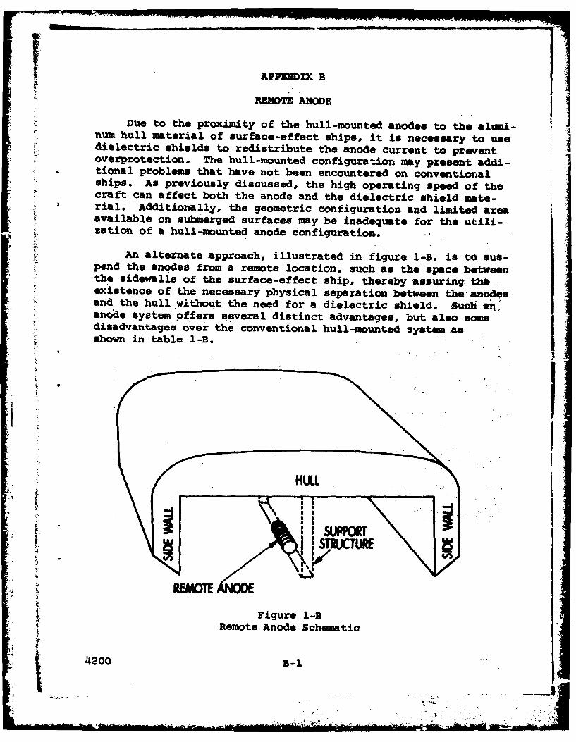
Due to the proximity of the hull-mounted anodes to the alumi-num hull material of surface-effect ships, it is necessary to usedielectric shields to redistribute the anode current to preventoverprotection. The hull-mounted configuration may present addi-tional problems that have not been encountered on conventioralships. As previously discussed, the high operating speed of thecraft can affect both the anode and the dielectric shield mate-rial. Additionally, the geometric configuration and limited areaavailable on submerged surfaces may be inadequate for the utili-zation of a hull-mounted anode configuration.
An alternate approach, illustrated in figure 1-B, is to sus-pend the anodes from a remote location, such as the space betweenthe sidewalls of the surface-effect ship, thereby assuring thaexistence of the necessary physical separation between thea'nodesand the hull without the need for a dielectric shield. Suc ahanode system offers several distinct advantages, but also somedisadvantages over the conventional hull-mounted system as
* shown in table 1-B.
S I2
2- I'k.
REMOT
Figure 1-B. Remote Anode Schematic
4200B-J .*.O0l-i"'

TABLE 1-B - ADVANTAGES ANDDISADVANTAGES OF REMOTE ANODE SYSTEM
o p Advanago s Disadvntges
1. Eliminates danger of 1. No comrcial units
overprotection due to shield availablejall units must befailure. specially designed and
custom built.2. More even current distri-bution to hull. 2. 'No operational experi-
ence has been gained with3. Reduces through-hull such systems.wiring penetrations.
3. Design difficulties for4. Reduces complexity of rigid lightweight anoderunning wires through or supporting structure.around fuel tanks insidewalls., 4. Design difficulties in
insulating anode from5. Eliminates cost of di- support structure.electric shield materials,application and maintenance. 5. May add more hydrody-
namic drag than conven-6. Eliminates dielectric tional hull-mounted anodes.shield weight.
6. May increase draft of7. Fewer reference cells craft.required.
7. More susceptible to8. Adequate protection by damage from floating orsingle anode, partially submerged debris.
9, Sidewll structure not 8. Loss of anode mightaffected as with hull- result in damage to rearmounted anodes. skirt.
4200 9-2
10

To deliver a current of 400 amperes to the hull, a remoteanode made from platinized titanium would have to have a surfacearea of 4 fta , and an anode of platinized tantalum requires anarea of 60 ins. This could be in the for& of a hydrodynamicallyefficient teardrop or foil shape, a long bar or tube, or a platesimilar to the stabilizers or rudders. It would have to be sus-pended even with, or below, the keel, with the optimum positionbeing 2-3 feet below the keel. In this pcsition, the anodewould be less affected by wave action.
The anode supporting structure would probably have to bebraced from the sidewalls. This structure must be capable ofwithstanding the thwartships force on the anode in extreme turns,the drag force at maximum craft velocity, and have the minimumof submerged frontal area during high velocity operation to mini-mize drag. Retractability for emergency high-speed operation,or to avoid damage by floating debris, may be necessary.
The remote anode concept appears to be a feasible approachto cathodic protection of surface-effect ships. Further studies,principally structural and hydrodynamic, will have to be con-ducted to determine the specific effects of each type of anodeconfiguration on craft performance. Also, studies must be madeto determine the expected current-delivering lifetime of variousanode materials, such as platinum-coated tantalum, under high-speed conditions.
4200 3-3
- ..
- . .l .. .. . .. .. . I . ' . .....

VECIASSiPZD -
- DOWWEMT COMMIL DATA.- It. 9S esmof ft'eia~~~l'Itl be& lot "aItee&t so" Mdm a tlet. all ale tumid .. M, woe0ns m $ efteuujjs
1. ORIGINATING ACTIVITY (CPMOIftiM010l am& RePOR? OCCUmTY CLANillCA?,@NNaval Ship Research and Development Contes MZA"hZVZU)Annapolis, Maryland 214102 s a
11. eePPT TTLEimpesse CurenCathodic protection for Surface Effect Ships
4. 6SRIPIV Noas(7"0p of J"tip ad MIUI&t dm10.
Reserchand DevelopmentS. AU ?r UI (Fie m". Will ill last "ams)
Harvey P. Back Dan A. DavisBoyce 3. M iller ?kN .OP; p
0. MUPOR? OATS 711. TOTAL. NO. or Ill 7.NO PUek.el A 217& 460MCW-ORGRANT NO. So. ORIMOWSU M19PORT HNMDURIS)9
19 ak Area 94629 4200
work~kit 1-2813-54 TE UPR O AWOINW
so. DISn"UTqeGuy. mYATEMEN
Distribution limited to U.S. Government agencies onlyr Test andzvaluation, July 1974. other requests for this document must be
C HAMT (I'K 17)
A laboratory investigation was conducted to provide background infor-mation for impressed-current cathodic protection of surface-effectships. The optimum protection potential was identified by performingpolarization experiments in flowing seawater (0-77 knots). Currentrequirements, at this potential level, were generated for 535 1008 bycombining the laboratory results with calculated surface areas of thewetted hull and appendage components. impressed-current cathodic pro -tection for surface effect ships is discussed from the viewpoint of tcraft designers. After a brief explanation of the fundamstal princi-plea of cathodic protection,* the function of an impressed-currentsystem on surface-effect craft is discussed in general, and a designprocedure is outlined and specifi 'cally applied to 838 1008. A brie
£ discussion of comm~ercial1ly available cathodic -protection -systemcomponents is presented.
I (Authord)
D D INOV .1473 MA 10 .- " %
* .4.

Elecrical CtIcopin
Sheldtinag oun
CorrosVo
CaIttown1(ApEndage