5g masterclass series: towards 6g
TRANSCRIPT

5G Masterclass series:
Towards 6G
Prof. Bart Smolders
Center for wireless technology Eindhoven
Department of Electrical Engineering
Eindhoven University of Technology

Content
• Trends in wireless communication
• What is 5G and 5G New Radio?
• Power consumption dilemma in 5G New Radio
• Looking forward towards 6G
2

Trends in Wireless communications
3

Trend 1: Increase of operational frequency
41900 1920 1940 1960 1980 2000 2020
10-3
10-2
10-1
100
101
102
Year
Fre
quency [
GH
z]
Frequency versus year of introduction
TV
GSM
Satellite
TV
AM
FM
Car radar
60 GHz
WLAN

Trend 2: Increase in bandwidth:Edholm’s Law
Source: IEEE spectrum, 2004 5
Required Bandwidth/datarate doubles each 18 months
Wireless growing faster than wired

1st GENERATION wireless network
• Basic Voice service
• Analog Based Protocols
2.4 Kbps
1G~1980
The foundation of
mobile telephony
2nd GENERATION wireless network
• Designed for voice
• First digital standards (GSM,CDMA)
64 Kbps
2G~1990
Mobile telephony
for everone
3rd GENERATION wireless network
• Designed for voice and data
• First mobile broadband
• Voice through circuit & Data-Packet Switching
2 Mbps
3G~2000
The foundation of
mobile broadband
4th GENERATION wireless network
• Designed Primarily for Data
• IP based protocol
• True Mobile broadband.
100 Mbps
4G~2010
Mobile broadband
enhanced
5th GENERATION wireless network
• 1000x increase in capacity
• Support for 100+ billion connections
• Below 1ms latency
10 Gbps
5G~2020
Embracing a
networked society
6th GENERATION wireless network
• Extension to (sub) mm-wave frequencies
• Real-time cloud computing
1 Tbps
~2030
6G
Enabling a smart
sustainable society
Evolution of wireless standards
6
Compare with Edholms law: factor 2 more BW in 1.5 year 2^(10/1.5)=101

What is 5G?
7

Requires New Radio (NR)
at mm-waves
What is 5G?
• Source: 5G PPP Architecture Working Group, “View on 5G Architecture (Version 2.0),” July 2017 , www.5g-ppp.eu 8
5GURLLC
Ultra-Reliable and Low Latency Communications
Very high reliability
mMTCMassive Machine
Type CommunicationsLow-cost, low-energy
eMBBExtreme Mobile Broadband
High date rate, high-traffic volume

Radio Access in 5G
• Source: 5G PPP Architecture Working Group, “View on 5G Architecture (Version 2.0),” July 2017 , www.5g-ppp.eu 9
Gradual migrationFrom 2020 onwards
LTE Evolution New Radio (NR)
1 GHz 10 GHz3 GHz 30 GHz 100 GHz 1 GHz 10 GHz3 GHz 30 GHz 100 GHz

3.5 GHz30 GHz
“mm-wave New Radio”

NR System embeddingOption 1: Non-standalone operation with LTE master
• Source: 5G PPP Architecture Working Group, “View on 5G Architecture (Version 2.0),” July 2017 , www.5g-ppp.eu 11
Data
LTE
Ctrl
Data
NR

Power consumption in 5G/6Gusing New-Radio
13
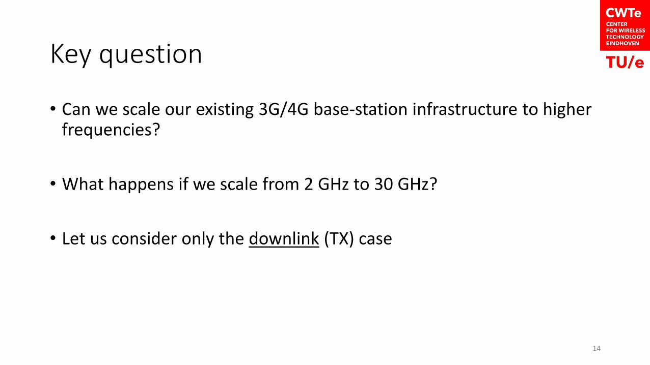
Key question
• Can we scale our existing 3G/4G base-station infrastructure to higherfrequencies?
• What happens if we scale from 2 GHz to 30 GHz?
• Let us consider only the downlink (TX) case
14

Existing base-stations for 3G/4G Wireless Communication
• Frequency 0.8-2.5 GHz
• Power consumption ~ 5kW
• Netherlands: 43933 base stations (2G/3G/4G)1
• So currently about 219 MW power dissipation
15• 1 https://www.antennebureau.nl/onderwerpen/algemeen/antenneregister

Spherical wave expansionfrom point source
R
𝑃𝑡
𝑆 =𝑃𝑡
4𝜋𝑅2Power density at surface sphere
Pt: total radiated power

Downlink, Link Budget
17
Pr , Gr
R
Pt , Gt
22
2
0
2 )4(4 R
GGP
R
AGPP rtet tt
r
==
min,
2
2
0
)4( r
rt
P
GGPR t
=

Simple “back-of-the-envelope” calculation, 2 GHz vs. 30 GHz
18
2 GHz
Wavelength: 0=15cm4 Tx antenna elements with 3dB gain each: Gt=8 (9dBi)Rx antenna omni-directional: Gr=1.Output power: 100 W (50 dBm)Sensitivity Pr,min = -70 dBm (=10-10W)
kmP
GGPR
r
rtt 33)4( min,
2
2
0 =
30 GHz
Wavelength: 0=1cm4 Tx antenna elements with 3dB gain each: Gt=8 (9dBi)Rx antenna omni-directional: Gr=1.Output power: 100 W (50 dBm)Sensitivity Pr,min = -70 dBm (=10-10W)
kmP
GGPR
r
rtt 2.2)4( min,
2
2
0 =

Simple “back-of-the-envelope” calculation, 2 GHz vs. 30 GHz
19
30 GHz
Wavelength: 0=1cm4 Tx antenna elements, Gt= 9dBiRx antenna omni-directional: Gr=1.
Output power: 22500 W (73.5 dBm)Sensitivity Pr,min = -70 dBm (=10-10W)
2 GHz
Wavelength: 0=15cm4 Tx antenna elements, Gt = 9dBiRx antenna omni-directional: Gr=1.Output power: 100 W (50 dBm)Sensitivity Pr,min = -70 dBm (=10-10W)
kmP
GGPR
r
rtt 33)4( min,
2
2
0 =
kmP
GGPR
r
rtt 33)4( min,
2
2
0 =

Consequence in Power consumptionEstimations!
20
3G/4G 5G
Frequency 2 GHz 30 GHz
Power per BST* 4+1=5 kW 4+225*5=1129 kW
Total Power in Netherlands* 219 MW 49 GW
#Wind mills (2 MW each) in NL 109 24500
1In May 2017, The Netherlands hosted 43933 2G/3G/4G antennes, see https://www.antennebureau.nl/onderwerpen/algemeen/antenneregisterAt this moment the PA efficiency is about a factor 5 worse at 30 GHz as compared to 2GHz. 10% of RF energy effectively radiated

Uplink case
• Uplink might be even more important than downlink at mm-wave.
• Link budget is not symmetrical!
• Mobile user does not have a lot of power or space.
• We need a large antenna at the base-station with electronic scanning
21

Solution: Use a large antenna array
22
30 GHzWavelength: 0=1cm871 Tx antenna elements, Gt=32.4 dBiRx antenna omni-directional: Gr=1.Output power: 100 W (50 dBm)Sensitivity Pr,min = -70 dBm (=10-10W)
30 GHzWavelength: 0=1cm4 Tx antenna elements, Gt= 9dBiRx antenna omni-directional: Gr=1.Output power: 22500 W (73.5 dBm)Sensitivity Pr,min = -70 dBm (=10-10W)
2 GHzWavelength: 0=15cm4 Tx antenna elements, Gt = 9dBiRx antenna omni-directional: Gr=1.Output power: 100 W (50 dBm)Sensitivity Pr,min = -70 dBm (=10-10W)
kmP
GGPR
r
rtt 33)4( min,
2
2
0 =
kmP
GGPR
r
rtt 33)4( min,
2
2
0 =
kmP
GGPR
r
rtt 33)4( min,
2
2
0 =

Can we come up with solutions in NL?
• The Netherlands has a strong position in:• Phased-arrays, e.g. Thales, ASTRON, TNO, ESTEC and TU’s.
• Silicon-integrated technology and Power amplifiers for base stations, e.g. NXP, TNO, Omniradar, Ampleon and TU’s
23

Phased-array radars from the Netherlands: SMART-L and APAR
PAGE 24
Long range L-band
surveillance
With secondary radar (IFF)
Ref: M.C. Van Beurden, A.B. Smolders, IEEE Trans. AP, 2002, pp.1266-1273

Silicon TechnologiesFt of IC Technology vs Year [ITRS]
26ITRS= International Technology Roadmap for Semiconductors
1990 1995 2000 2005 2010 2015 202010
100
1000
Year
Tra
nsit F
req
uency [
GH
z]
RFCMOS SiGe BiCMOS
Sat
TV
24 GHz
Car radar
60 GHz
WLAN
77 GHz
Car radar
94 GHz
Imaging
NXP
Qubic4Xi
20~30 GHzPoint to point

Do we need more?
• Yes!
• Phased-arrays are too power hungry and too expensive
• Need new antenna concepts
• Further integration in Silicon
• At mm-waves, smaller cells will be used (< 300 m)
27

European project SILIKASilicon-Based Ka-Band Massive MIMO Systems for New Telecommunication Services (5G-NR)
See: www.silika-project.eu 28
Funded by the European Union

Base station cell at mm-waves (28.5 GHz)
29
Scenario: Urban environment

5G New Radio mm-wave Prototype
30/ Electrical Engineering – Electromagnetics group

5G New Radio mm-wave Prototype
31

5G New Radio mm-wave Prototype
32

What about safety in 4G versus 5G?
4G: Based on existing basestation antenna, 10 dipoles, Ptot=50 dBm (100W) Gelem=8 dBi, dual polarization.
5G: Based on EIRP=+65 dBm radiated power, required for a 250 m urban micro cell.
Safety limit: Advies in “Publicatieblad van de Europese Gemeenschappen” L 199/59, 30. 7. 1999 NL.

Looking forward towards 6G
34

Funded by the European Union
Efficient Millimetre-Wave Communications
for Mobile Users (6G)
Kick-Off Meeting01.04.2020
See: www.Mywave-project.eu
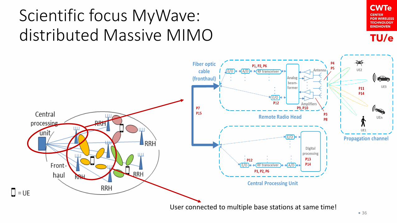
Scientific focus MyWave: distributed Massive MIMO
• 36User connected to multiple base stations at same time!

Next step: Feed-array using integrated antennas
Antenna-on-chip (AoC)
• Antenna launcher integrated in Silicon.
• No RF interconnect required anymore
• Wafer thinning can be applied to reduce silicon losses.
Demonstrator in BiCMOS
• AoC+LNA at 30 GHz
37
38
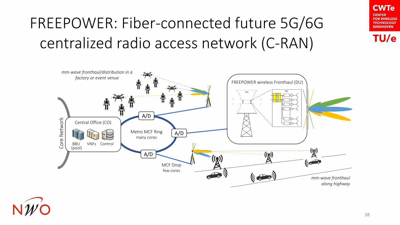
FREEPOWER: Fiber-connected future 5G/6G centralized radio access network (C-RAN)
PAFFPA
FREEPOWER wireless Fronthaul (DU)
Co
re N
etw
ork Central Office (CO)
BBU VNFs Control(pool)
Metro MCF Ringmany cores
A/D
MCF Dropfew cores
A/D
A/D
mm-wave fronthaulalong highway
mm-wave fronthaul/distribution in a factory or event venue

Prof. Ton Koonen
Electro-optical Communication Systems group (ECO)
Institute for Photonic Integration
Dept. Electrical Engineering
Eindhoven University of Technology
Optical Wireless Communication:The benefits of fiber without needing a fiber
European Research Council

[Dominic O’Brien, IPS Summer Topicals 2016]
⚫ Visible Light Communication with wide-coverage beams (<1Gbit/s, shared) ⚫ Beam-steered IR communication (>10Gbit/s, unshared)
Optical wireless communication – basic options

Breaking wireless barriers: free-space beam-steered optical communication
BROWSE’s system concept:
⚫ pencil beams →
no capacity sharing,
long reach
⚫ target:
10Gbit/s per beam
⚫ IR >1400nm →
Pbeam up to 10mW
⚫ passive diffractive beam steerer →
no local powering, easily scalable
⚫ -controlled 2D steering → embedded
control channel
⚫ easily scalable to many beams, just add -s
[Koonen et al, MWP2014]
[Koonen et al., JLT Oct. 2016, JLT May 2018, JLT Oct. 2018]
CCC
OXC
OXC = Optical Crossconnect
CCC = Central Communication
Controller
optical
fiber
access
network
MD = Mobile Device
PRA = Pencil-Radiating Antenna
1221 11
21
11
1112
222121
22
2212
11 22
PRA
MD

fibers
PRA
opticalreceivers
CCC with 2tunable transmitters
PRA
videossent
videosreceived
controllaptop
7 cells captured with IR camera at 2.5m
localization detector
MEMS switch
Lab demonstrator TU/e
⚫ Transfer of two high-def video streams
o Real-time
o Embedded in two 10Gb streams
⚫ Two PRA-s
o 2D array with 128 fibres
⚫ MEMS switch

2D fiber array and assembled beam steerer
Hexagonal 128 fibers array
Co-assembled with 50mmF/0.95 camera lens
Co-assembled with composite C+L band AWGR, 96+48 ports

Summary
• 5G will use mm-wave frequencies • 24.25-43 GHz for base stations in small cells• 71-86 GHz for Front-Haul/Back-Haul
• Existing concepts are too power hungry and far to expensive
• New antenna concepts and high level of integration in Silicon technologies are required.
• 6G will offer even higher capacity• Higher mm-wave frequencies (70-120 GHz)• Optical Wireless using IR or visible light.
44

Thank you !
PAGE
45

Back-up
• Providing 1000 times higher wireless area capacity and more varied service capabilities compared to 2010
• Facilitating very dense deployments of wireless communication links to connect over 7 trillion wireless devices serving over 7 billion people
• Saving up to 90% of energy per service provided. The main focus will be in mobile communication networks where the dominating energy consumption comes from the radio access network
• Reducing the average service creation time cycle from 90 hours to 90 minutes
• Creating a secure, reliable and dependable Internet with a “zero perceived” downtime for services provision
• Ensuring for everyone and everywhere the access to a wider panel of services and applications at lower cost
47 Source: 5G PPP Architecture Working Group, “View on 5G Architecture (Version 2.0),” July 2017 , www.5g-ppp.eu
Key objectives 5G