5g eve - d3.1 interworking capability definition and gap ... · cbis nokia cloudband infrastructure...
TRANSCRIPT

5G European Validation platform for Extensive trials
Deliverable D3.1
Interworking Capability Definition and Gap
Analysis Document

ii
Project Details
Call H2020-ICT-17-2018
Type of Action RIA
Project start date 01/07/2018
Duration 36 months
GA No 815074
Deliverable Details
Deliverable WP: WP3
Deliverable Task: T3.1
Deliverable Identifier: D3.1
Deliverable Title: Interworking Capability Definition and Gap Analysis
Document
Editor(s): G. Bernini
Author(s): G. Bernini, G. Landi, G. Carrozzo, P. G. Giardina, D.
Meridou, M. Molla, M. Lorenzo, V. Stavroulaki, K.
Trichias, P. Vlacheas, Y. Kritikou, C. Ntogkas, V.
Laskaridis, G. Agapiou, L. M. Contreras Murillo, J.
Rodriguez Martinez, L. L. Cantó, F. Moggio, M.
Iordache, M. Corriou, S. Morant, T. Doukoglou, I.
Barberana, R. Legouable, M. Agus, M. Caretti
Reviewer(s): R. Legouable, M. Yassin, W. Diego, C. Tsirakis, A.
Zabala, R. Perez
Contractual Date of Delivery: 31/12/2018
Submission Date: 21/12/2018
Dissemination Level: PU
Status: Final
Version: 1.0
File Name: 5G_EVE_D3.1_v1.0
Disclaimer
The information and views set out in this deliverable are those of the author(s) and do not
necessarily reflect the official opinion of the European Union. Neither the European
Union institutions and bodies nor any person acting on their behalf may be held
responsible for the use which may be made of the information contained therein.

ii
Deliverable History
Version Date Modification Modified by V0.1 23/07/2018 Table of Content G. Bernini
V0.2 18/09/2018 Draft Italian site capabilities G. Bernini
V0.3 9/10/2018 Draft Greek site capabilities K. Trichias, G. Agapiou, V.
Stavroulaki. D. Meridou
V0.4 16/10/2018 Draft Spanish site capabilities L. Luque Cantò, L. M.
Contreras
V0.5 26/10/2018 Draft French site capabilities M. Iordache
V0.6 6/11/2018 Smart Cities requirements F. Moggio
V0.7 13/11/2018 Smart Tourism and Industry 4.0
requirements
M. Molla
V0.75 20/11/2018 Use case requirements L. Luque Cantò, L. M.
Contreras, G. Landi, K.
Trichias, R. Legouable, P.
Vlacheas, Y. Kritikou
V0.78 22/11/2018 Interworking architecture and
Technical Gaps
G. Bernini, M. Molla
V0.8 28/11/2018 Consolidation of sections 2 and
3, Introduction, Conclusions
G. Bernini, G. Landi
V0.85 29/11/2018 Consolidation sections 4 and 5 M. Molla
V0.9 30/11/2018 Version for internal review G. Bernini
V0.95 12/12/2018 Implementation of internal
review comments
G. Bernini, G. Landi, M.
Molla, F. Moggio, K.
Trichias, M. Iordache
V0.97 14/12/2018 Section 4 and Section 5 review G. Bernini, G. Landi, M.
Molla, M. Lorenzo
V0.99 17/12/2018 Document finalization,
executive summary
G. Bernini, M. Molla
V1.0 18/12/2018 Final version G. Bernini
iii
Table of Contents
LIST OF ACRONYMS AND ABBREVIATIONS ........................................................................................................ IV
LIST OF FIGURES ....................................................................................................................................................... VIII
LIST OF TABLES ......................................................................................................................................................... VIII
EXECUTIVE SUMMARY .............................................................................................................................................. 10
1 INTRODUCTION ............................................................................................................................................... 11
1.1 MOTIVATION AND SCOPE CLARIFICATION ................................................................................................................. 11 1.2 OBJECTIVES OF THE DOCUMENT ................................................................................................................................ 13 1.3 DOCUMENT STRUCTURE ............................................................................................................................................ 14
2 SITE FACILITIES’ SERVICE CAPABILITIES AND FEATURES ............................................................. 15
2.1 GREEK SITE FACILITY ................................................................................................................................................ 15 2.1.1 Overview of site capabilities ............................................................................................................................. 15
2.2 SPANISH SITE FACILITY.............................................................................................................................................. 20 2.2.1 Overview of site capabilities ............................................................................................................................. 20 2.2.2 Main services and features offered ................................................................................................................... 21
2.3 FRENCH SITE FACILITY .............................................................................................................................................. 23 2.3.1 Overview of site capabilities ............................................................................................................................. 23 2.3.2 Main services and features offered ................................................................................................................... 25
2.4 ITALIAN SITE FACILITY .............................................................................................................................................. 29 2.4.1 Overview of site capabilities ............................................................................................................................. 29 2.4.2 Main services and features offered ................................................................................................................... 30
3 TECHNICAL INTERWORKING REQUIREMENTS FROM VERTICAL USE CASES .......................... 34
3.1 5G EVE USE CASE TECHNICAL REQUIREMENTS ........................................................................................................ 34 3.1.1 Smart Transport: Intelligent railway for smart mobility ................................................................................... 34 3.1.2 Smart Tourism: Augmented Fair experience .................................................................................................... 36 3.1.3 Industry 4.0: Autonomous vehicles in manufacturing environments ................................................................. 38 3.1.4 Smart Energy: Fault Management for distributed electricity generation in smart grids .................................. 39 3.1.5 Smart Cities: Safety and Environment .............................................................................................................. 41 3.1.6 Media & Entertainment..................................................................................................................................... 47
4 TARGET INTERWORKING CAPABILITIES, FEATURES AND SERVICES ......................................... 52
4.1 PRELIMINARY INTERWORKING FRAMEWORK ARCHITECTURE .................................................................................... 52 4.1.1 Overview of the interworking framework components ...................................................................................... 54
4.2 INTERWORKING FRAMEWORK EVOLUTION ROADMAP ................................................................................................ 55 4.3 TARGET SITE FACILITIES INTERWORKING CAPABILITIES ............................................................................................ 57
4.3.1 UE and SIM cards logistic ................................................................................................................................ 59 4.3.2 Basic Subscriber configuration ......................................................................................................................... 59 4.3.3 Radio Access Network selection and configuration .......................................................................................... 59 4.3.4 Edge Computing ................................................................................................................................................ 60 4.3.5 NFV / Slice orchestration .................................................................................................................................. 60 4.3.6 SDN-based network control .............................................................................................................................. 61 4.3.7 Monitoring ........................................................................................................................................................ 61 4.3.8 Testing tools ...................................................................................................................................................... 61 4.3.9 Cross-site connectivity ...................................................................................................................................... 61
5 SITE FACILITIES’ TECHNICAL GAPS AND INTERWORKING RECOMMENDATIONS ................. 63
5.1 GREEK SITE FACILITY ................................................................................................................................................ 66 5.2 SPANISH SITE FACILITY.............................................................................................................................................. 67 5.3 FRENCH SITE FACILITY .............................................................................................................................................. 69 5.4 ITALIAN SITE FACILITY .............................................................................................................................................. 71
6 CONCLUSIONS .................................................................................................................................................. 73
REFERENCES ................................................................................................................................................................. 74

iv
List of Acronyms and Abbreviations
Acronym Meaning
3GPP Third Generation Partnership Project
5G Fifth Generation
5G-PPP 5G Infrastructure Public Private Partnership
AGV Automated Guided Vehicle
API Application Programming Interface
AR Augmented Reality
BBU BaseBand Unit
BGP Border Gateway Protocol
BH Backhaul
BSS Business Support System
C-RAN Cloud Radio Access Network
CAPEX CAPital EXpenditures
CAT-M Category M
CBIS Nokia CloudBand Infrastructure Software
CEE Ericsson Cloud Execution Environment
CLI Command Line Interface
COTS Commercial Off The Shelf
CP Control Plane
CPRI Common Public Radio Interface
CU Central Unit
CUPS Ericsson Control and User Plane Separation
DC Dual Connectivity
DG Distributed Generator
DP Data Plane
DPDK Data Plane Development Kit
DRB Data Radio Bearer
DU Distributed Unit
DWDM Dense Wavelength Division Multiplexing
eMBB Enhanced Mobile BroadBand
EMS Equipment Management System
eNB Evolved Node B
ENM Ericsson Network Manager
ETSI European Telecommunications Standards Institute
FDD Frequency Division Duplex

v
FH Fronthaul
gNodeB Next generation Node B
GRE Generic Routing Encapsulation
HARQ Hybrid automatic repeat request
HCI Hyper Converged Infrastructure
HD High Definition
HDR HD Recording
HMD Head Mounted Display
HW Hardware
IoT Internet of Things
IP Internet Protocol
IRU Indoor Radio Unit
IT Information Technology
I/W Interworking
KPI Key Performance Indicator
LAN Local Area Network
LCT Local Control Terminal
LTE Long Term Evolution
M2M Machine to Machine
M-MIMO Massive MIMO
MANO MANagement and Orchestration
ME Mobile Edge
MEC Multi-access Edge Computing
MIMO Multiple Input Multiple Output
MME Mobility Management Entity
mMTC Massive Machine Type Communication
NB-IoT Narrow Band Internet of Thing
NFVI Network Function Virtualization Infrastructure
NFVO Network Function Virtualization Orchestrator
NGC Next Generation Core
NR New Radio
NS Network Service
NSA Non-Standalone
NSD Network Service Descriptor
OAI Open Air Interface
ONAP Open Network Automation Platform
ONOS Open Network Operating System

vi
OPEX OPerating EXpenses
OPNFV Open Platform for NFV
OSM Open Source MANO
OSS Operation Support System
OVS Open Virtual Switch
P2P Peer to Peer
PCRF Policy and Charging Rules Function
PGW Packet Data Network Gateway
PLC Programmable Logic Controller
PNF Physical Network Function
PoP Point of Presence
QAM Quadrature Amplitude Modulation
QoE Quality of Experience
QoS Quality of Service
RAN Radio Access Network
RAT Radio Access Technology
REST Representation State Transfer
RRC Radio Resource Signaling
RRH Remote Radio Head
RRU Remote Radio Unit
RTT Round Trip Time
SD Standard Definition
SDN Software Defined Networking
SGSN Serving GPRS Support Node
SIM Subscriber Identity Module
SR-IOV Single-Root Input / Output Virtualization
SW Software
TDD Time Division Duplex
TOSCA Topology and Orchestration Specification for Cloud Applications
TTI Transmission Time Interval
UC Use Case
UE User Equipment
UHF Ultra-High Fidelity
UP User Plane
UPF User Plane Function
uRLLC Ultra-Reliable Low Latency Communication
vCPE Virtual Customer Premise Equipment
vii
vCUDB Centralized User Database
vEPC Virtual Evolved Packet Core
vIMS Virtual IP Multimedia Subsystem
VIM Virtual Infrastructure Manager
VNF Virtual Network Function
VNFD Virtual Network Function Descriptor
VNFM Virtual Network Function Manager
VNS Virtual Network Service
VOD Video On Demand
VPN Virtual Private Network
VR Virtual Reality
WAN Wide Area Network
WIM Wide Area Network Infrastructure Manager
XHAUL Fronthaul/Backhaul

viii
List of Figures
Figure 1: 5G EVE interworking framework overview ...................................................................................... 12
Figure 2: French node architecture .................................................................................................................... 24
Figure 3: French site as a federation .................................................................................................................. 24
Figure 4 Inter-working architecture ................................................................................................................... 37
Figure 5: 5G PPP scenario: eMBB and URLLC. .............................................................................................. 48
Figure 6: Video 360° TO scenario deployment ................................................................................................. 49
Figure 7: Video 360° TP scenario deployment ................................................................................................. 49
Figure 8: Video 360° SI scenario deployment................................................................................................... 50
Figure 9: Video 360° SO scenario deployment ................................................................................................. 50
Figure 10: Preliminary interworking framework architecture ........................................................................... 52
Figure 11: 3GPP and NFV information models potential mapping (source [37])............................................. 53
Figure 12: Interworking framework roadmap ................................................................................................... 56
List of Tables
Table 1: Greek site facility – overview of data plane service capabilities ........................................................ 16
Table 2: Greek site facility – overview of control plane service capabilities .................................................... 17
Table 3: Greek site facility – overview of Nokia orchestration plane service capabilities ................................ 19
Table 4: Spanish site facility – overview of data plane service capabilities...................................................... 21
Table 5: Spanish site facility – overview of control plane service capabilities ................................................. 22
Table 6: Spanish site facility – overview of orchestration plane service capabilities ....................................... 23
Table 7: French site facility – overview of pre-commercial data plane service capabilities ............................. 25
Table 8: French site facility – overview of pre-commercial control plane service capabilities ........................ 26
Table 9: French site facility – overview of open-source control plane service capabilities .............................. 27
Table 10: French site facility – overview of pre-commercial orchestration plane service capabilities ............. 28
Table 11: French site facility – overview of open-source orchestration plane service capabilities .................. 29
Table 12: Italian site facility – overview of data plane service capabilities ...................................................... 30
Table 13: Italian site facility – overview of control plane service capabilities ................................................. 31
Table 14: Italian site facility – overview of orchestration plane service capabilities ........................................ 32
Table 15: Smart Transport Use Case: deployment technical requirements ....................................................... 35
Table 16: Smart Transport Use Case: runtime technical requirements ............................................................. 35
Table 17: Smart Transport Use Case: monitoring/analysis technical requirements .......................................... 36
Table 18 Smart Tourism Use Case: deployment technical requirements .......................................................... 37
Table 19: Smart Tourism Use Case: monitoring/analysis technical requirements ............................................ 38
Table 20: Industry 4.0 Use Case: deployment technical requirements.............................................................. 38

ix
Table 21: Industry 4.0 Use Case: operation technical requirements ................................................................. 39
Table 22: Industry 4.0 Use Case: monitoring/analysis technical requirements ................................................. 39
Table 23: Smart Energy Use Case: deployment technical requirements ........................................................... 40
Table 24: Smart Energy Use Case: monitoring/analysis technical requirements .............................................. 40
Table 25: Smart Turin Use Case scenario: deployment technical requirements ............................................... 41
Table 26 Smart Turin Use Case scenario: Runtime technical requirements ..................................................... 42
Table 27: Smart Turin Use Case scenario: monitoring/analysis technical requirements .................................. 42
Table 28: Connected Ambulance Use Case scenario: deployment technical requirements .............................. 43
Table 29: Connected Ambulance Use Case scenario: operation technical requirements .................................. 43
Table 30: Connected Ambulance Use Case scenario: monitoring/analysis technical requirements ................. 44
Table 31: Health monitoring and forecasting, smart mobility and smart home Use Case scenario: deployment
technical requirements ....................................................................................................................................... 45
Table 32: Health monitoring and forecasting, smart mobility and smart home Use Case scenario: runtime
technical requirements ....................................................................................................................................... 46
Table 33: Health monitoring and forecasting, smart mobility and smart home Use Case scenario:
monitoring/analysis technical requirements ...................................................................................................... 46
Table 34: UHF Media, On-Site Live Event Experience and Immersive and Integrative Media Use Case scenario:
deployment technical requirements ................................................................................................................... 47
Table 35: UHF Media, On-Site Live Event Experience and Immersive and Integrative Media Use Case scenario:
operation technical requirements ....................................................................................................................... 48
Table 36: UHF Media, On-Site Live Event Experience and Immersive and Integrative Media Use Case scenario:
monitoring/analysis technical requirements ...................................................................................................... 48
Table 37: Virtual visit over 5G Use Case scenario: deployment technical requirements ................................. 50
Table 38: Virtual visit over 5G Use Case scenario: monitoring/analysis technical requirements ..................... 51
Table 39: Requirements per 5G Service Type ................................................................................................... 56
Table 40: Summary of identified target basic capabilities to be implemented in the site facilities .................. 57
Table 41 Summary of identified inter-site connectivity requirements .............................................................. 58
Table 42: Match between target interworking capabilities/features and 5G EVE vertical use case scenarios.. 64
Table 43: Preliminary set of basic technical gaps and recommendations for the Greek site facility ................ 66
Table 44 Preliminary set of cross-site requirements and recommendations for the Greek site facility ............ 66
Table 45: Preliminary set of basic technical gaps and recommendations for the Spanish site facility ............. 67
Table 46 Preliminary set of cross-site requirements and recommendations for the Spanish site facility ......... 68
Table 47: Preliminary set of basic technical gaps and recommendations for the French site facility ............... 69
Table 48: Preliminary set of cross-site requirements and recommendations for the French site facility .......... 70
Table 49: Preliminary set of basic technical gaps and recommendations for the Italian site facility ................ 71
Table 50: Preliminary set of cross-site requirements and recommendations for the Italian site facility ........... 72
5G EVE (H2020-ICT-17-2018)
Deliverable D3.1 Page 10 / 76
Executive Summary
This deliverable provides a report about the capabilities that have to be supported by a generic site facility
operating in the 5G EVE framework, in order to enable its interoperability and interworking with the whole 5G
EVE system. The definition of such capabilities is initially driven from the design of the 5G EVE use cases, as
specified in Work Package 1, but has the objective to cover a wider and more generalized scope to enable the
future porting of further use cases on the 5G EVE platform. This approach will help to open the system towards
additional 5G vertical experimenters, beyond those already present in 5G EVE consortium, for example in
support of use cases and trials in ICT-19 projects.
This deliverable initially identifies the capabilities offered by the four 5G EVE site facilities in Greece, Spain,
France and Italy, in terms of infrastructure resources (for both computing/storage and network connectivity)
and control, orchestration, monitoring or management tools deployed in each site. Special attention is also
dedicated to the interconnectivity between different site facilities, which enables the delivery of cross-site 5G
services. The analysis takes into account not only the current status of the target sites, but also the plans for
future deployments and extensions, as documented in deliverable D2.1 and deliverable D2.2, in order to capture
a complete and medium-term picture of the capabilities which will support the experiments on 5G services. It
is important to note that the survey of the site facilities reported in this document starts from the specification
provided from Work Package 2, but provides a different perspective. On one hand Work Package 2 is mostly
focused on deployment, installation and configuration issues, with the objective of designing and building the
infrastructure. On the other hand, Work Package 3, and thus the analysis performed in this deliverable, is mostly
interested in the functionalities, capabilities and interfaces offered by each facility, to define a common and
abstract interworking model across the whole platform, regardless of the internal details related to how a given
feature is implemented in the particular site.
Following a similar direction, all the 5G EVE target use cases, which have been previously described in
deliverable D1.1 from the perspective of the verticals, are analyzed here with the objective of identifying the
requirements associated with the deployment, the runtime operation and the monitoring of the associated
services. The list of resulting requirements has been elaborated and generalized to produce a comprehensive set
of functionalities, features, capabilities and services that are needed to deliver and manage the full variety of 5G
services in an end-to-end environment, providing also the required tools for their experimental assessment and
performance validation in a realistic 5G environment. This list provides a reference and a guideline for the
capabilities that each of the 5G EVE site facilities should provide to enable its integration with the 5G EVE
platform. Similarly, it also provides the foundations of the internal functionalities that the 5G EVE Interworking
Framework will need to support and implement, identifying the kind of abstract primitives to be adopted in its
interaction with all the underlying facilities.
Indeed, the definition of these target “Interworking Capabilities” constitutes one of the main outcomes of this
deliverable. Starting from this pillar, the deliverable also derives an initial sketch of the Interworking Framework
functional architecture, as well as the technical gaps between the current (or planned) facilities deployment and
the target functionalities which should be offered by each 5G EVE site facility. The architectural outcomes are
expected to feed Work Package 1 activities, related to the design of the whole 5G EVE platform, and the future
activities in Work Package 3 for the definition of reference interworking information model and the
implementation of the Interworking Framework. The analysis of the technical gaps will provide inputs to Work
Package 2, driving any needed updates in the current deployments of the 5G EVE facilities. Moreover, the target
Interworking Capabilities will also provide a sort of template for any potential external facility that may want
to join the 5G EVE framework in the context of future collaborations (e.g. to integrate local trial sites made
available from ICT-19 projects that would like to interoperate with the 5G EVE platform). In particular, this
template identifies the full list of functionalities and capabilities that a generic site facility, independently on its
internal infrastructure and specific technologies, should expose towards the 5G EVE Interworking Framework
to be compliant with the whole design and principles of the overall system, thus enabling its possible integration
with the 5G EVE platform.

5G EVE (H2020-ICT-17-2018)
Deliverable D3.1 Page 11 / 76
1 Introduction
1.1 Motivation and scope clarification
5G EVE aims at building a 5G end-to-end facility composed of four interconnected European sites in Greece,
Spain, France and Italy. The main goal is to enable the experimentation and validation of 5G pilots from vertical
industries, providing unified and open access to a full set of 5G capabilities. The 5G EVE end-to-end facility
will initially host a selection of project use cases to be deployed by verticals participating in the project. These
use-cases have been described in deliverable D1.1 [1], in terms of execution scenario, target KPIs and general
requirements for each vertical domain. Additionally, these use cases have been grouped around six main
categories: i) Smart Transport: Intelligent railway for smart mobility ii) Smart Tourism: Augmented Fair
experience, iii) Industry 4.0: Autonomous vehicles in manufacturing environments, iv) Utilities (Smart Energy):
Fault management for distributed electricity generation in smart grids, v) Smart cities: Safety and Environment,
vi) Media & Entertainment: UHF Media, On-site Live Event Experience and Immersive and Integrated Media.
More external vertical industries and related use cases will be involved at later stages in the project, mostly from
ICT-19 projects starting from Q2-2019, with the aim of executing more and more 5G experiments over the 5G
EVE end-to-end facility and thus strengthen testing and validation of the deployed 5G technologies.
A detailed description of each 5G EVE site facility in terms of deployed 5G technologies and elements, together
with the required network control, management and orchestration tools, has been provided in deliverable D2.1
[2]. Moreover, the roadmap for the implementation of each 5G EVE site facility has been also reported in
deliverable D2.2 [3], along with the planning of the deployment of 5G enabling technologies, tools and
functionalities, aiming to provide the initial access to the vertical partners in the project for use cases
experimentation from April 2019.
In summary, these three initial 5G EVE specifications, i.e. D1.1 [1], D2.1 [2] and D2.2 [3], represent the ground
to proceed with the 5G EVE end-to-end facility design and development, starting from each site facility
implementation, towards the upper layers of the 5G EVE platform, namely, the integrated portal (WP4) for 5G
experimentation and validation (WP5), and the interworking framework (WP3). As said, the main goal of 5G
EVE is to build a truly integrated end-to-end 5G experimentation facility, where the validation services offered
by the four sites are exposed to verticals and their applications as a unified platform service. The interworking
framework has thus the role of abstracting the specific logics and tools available in each site, exposing the whole
multi-site infrastructure through a unified and site-agnostic information model towards the upper layers of the
5G EVE architecture. This means that the heterogeneous 5G capabilities and orchestration solutions adopted in
each site facility are properly abstracted to provide a common and unified end-to-end experimentation and
validation facility. Moreover, the 5G EVE platform should enable those vertical use cases and experiments that
may have specific requirements for deployment and execution across multiple site facilities, still hiding to
verticals the low-level details and the multi-site nature of the infrastructure.
Therefore, the role of 5G EVE interworking framework is crucial to ensure interoperability of validation
services offered by the various sites of 5G EVE and to perform tests involving several sites, achieving end-to-
end integration of the four site facilities. The interworking framework has therefore two main roles and
objectives in the overall 5G EVE platform:
• Provide a common interworking model, to abstract the heterogeneous 5G capabilities and
orchestration solutions implemented in each 5G EVE site facility, and expose seamless services,
features, interfaces and Application Programming Interfaces (APIs) to the upper layers of the 5GEVE
integrated portal for enabling then to deliver unified validation and experimentation of vertical
services;
• Provide site facility interconnection means and mechanisms for enabling the deployment of use cases
and experiments involving multiple sites (multi-site use cases) in a transparent and seamless way for
verticals.

5G EVE (H2020-ICT-17-2018)
Deliverable D3.1 Page 12 / 76
On one hand, the first interworking objective above is valid for any kind of vertical use case experiment to be
validated, independently of its single or multi-site nature. This already poses challenging requirements on the
interworking framework itself, in terms of functionalities to achieve the common model and the exposure of
unified services towards the 5G EVE experimentation portal, as reported later in this document. As a
consequence, further requirements are posed on each 5G EVE site to expose a minimum set of capabilities,
features and services to enable such common interworking model. On the other hand, the second interworking
objective listed above aims to enable the validation of those vertical use case experiments that will be deployed
across multiple sites.
Figure 1 provides an overview of how the 5G EVE interworking framework is logically positioned with respect
to the four site facilities in Greece, Spain, France and Italy. It can be considered as an overarching layer sitting
on top of the site facilities that provides the abstraction, adaptation and cross-site functionalities required to
integrate the heterogeneous 5G capabilities, features and services under a common interworking model. This
allows providing a transparent and unified end-to-end facility to the 5G EVE integrated portal; thus, keeping
the complexity and implementation details within each site.
Figure 1: 5G EVE interworking framework overview
Therefore, the interworking framework deals with specific 5G capabilities in each site, and it exposes unified
and common APIs to provision end-to-end services and network slices in support of the vertical use case
experiments. This means that the interworking framework has to apply its abstraction, adaptation and multi-site
interconnection logics at different layers and different segments of 5G networks in each site. As depicted in
Figure 1, each site facility can be organized around three main layers: orchestration plane, control plane and
physical infrastructure layer (from now on referred as data plane). Starting from the bottom, the data plane
within each site is composed of the collection of Radio Access Network (RAN), edge and core network elements
that provide the 5G connectivity for a set of IT resources that are deployed in different geographical locations
to offer the computing and storage capabilities needed to run virtualized functions and applications. In particular,

5G EVE (H2020-ICT-17-2018)
Deliverable D3.1 Page 13 / 76
these resources can be distributed closer to the network edge, following the concept of the Multi-access Edge
Computing (MEC), or centralized in a small number of larger deployments, e.g. in Points of Presence (PoPs)
implementing a private cloud. In turn, on top of these data plane resources, each site can deploy a wide set of
control tools and solutions to properly provision and configure the 5G network connectivity in each of the
segments, including the IT part. These control features may include Virtualized Infrastructure Managers (VIM)
for the Network Function Virtualization (NFV) part, Mobile Edge Platform Managers for the MEC segment,
Software Defined Networking (SDN) controllers for the provisioning of transport networks and RAN
controllers for the dynamic configuration and allocation of Radio Access Technology (RAT) resources.
Furthermore, for the proper coordination of network services and slices provisioning across the different
segments and technologies within each site, dedicated tools and solutions are used at the orchestration plane,
including NFV orchestration, slice management and legacy Operation Support System (OSS) products.
For each of these three planes, the 5G EVE interworking framework provides the abstraction and adaptation
functionalities mentioned above, taking also into consideration that different sites will potentially provide a
different combination of features, functions and tools in each plane. As depicted in Figure 1, the interworking
framework also takes care to implement those site interconnection features, thus allowing, if required by vertical
use cases and experiments, to build a 5G EVE end-to-end interconnected data plane. However, any
interconnection at orchestration and control levels can be mediated by the interworking framework itself
following a kind of hierarchical approach.
This deliverable is the first outcome of WP3 and aims at identifying a minimum set of interworking capabilities
and features to enable an interoperable use of 5G technologies and services offered by the four 5G EVE site
facilities. This is achieved by further analyzing what each site facility offers at each plane (i.e. orchestration,
control, and data) in terms of services, features and APIs, beyond the specific technologies and tools reported
in D2.1 [2] and D2.2 [3]. Moreover, by establishing vertical oriented functional requirements from a deeper
technical analysis of 5G EVE use cases in D1.1, and by defining a preliminary interworking framework
architecture scheme, this deliverable also identifies an initial set of interworking technical gaps and
recommendations to be considered by each site facility for the implementation of the interworking model and
services in WP3.
1.2 Objectives of the document
This document aims at achieving a set of technical objectives related with the 5G EVE interworking framework:
• Collect, for each site facility, the main exposed services, features and APIs that have an impact on the
interworking framework capabilities at different layers, from data to control and orchestration planes,
as a further and deeper iteration and analysis of site facilities descriptions and implementation
roadmaps reported in D2.1 [2] and D2.2 [3];
• Identify the technical requirements to be met by the 5G EVE platform for deploying, operating,
monitoring and evaluate the performance of vertical services. These requirements are obtained by
analysing, from a technical point of view, the vertical-oriented use cases defined in D1.1 [1], in terms
of deployment scenario, service lifecycle workflows and target KPIs;
• Provide a preliminary interworking framework architecture and model scheme, as a collection of
services, tools and features aiming at addressing the technical functional requirements associated to
the vertical use cases;
• Identify a minimum set of control, management, monitoring, orchestration capabilities and features
that each site has to implement and expose towards the interworking framework;
• Identify a preliminary set of technical gaps to be filled at the interworking framework and in each of
the site facilities in order to meet the technical functional requirements at the global 5G EVE platform
level.
5G EVE (H2020-ICT-17-2018)
Deliverable D3.1 Page 14 / 76
1.3 Document structure
This deliverable is organized as follows:
• Section 2 provides an overview of the services, features and APIs implemented and provided by each
5G EVE site facility that have an impact on the interworking framework. It is the result of a critical
analysis of D2.1 [2] and D2.2 [3] outcomes, combined with a technical survey of the site facilities
deployment plans, to obtain information about the offered features and technology capabilities, useful
for the definition of the preliminary interworking framework architecture;
• Section 3 provides a set of technical interworking requirements derived from the technical analysis of
5G EVE vertical use cases, focused on the deployment, operation and monitoring/data analysis of the
associated 5G services;
• Section 4 reports the preliminary interworking framework architecture and identifies a set of target
capabilities and features that each 5G EVE site facility shall provide and expose for the realization of
the interworking model;
• Section 5 provides a preliminary list of interworking technical gaps and recommendations against the
identified target capabilities and functionalities that the site facilities need to implement to deliver the
5G services in support of the reference 5G EVE vertical use cases;
• Section 6 provides some concluding remarks, including highlights on future related work within Task
T3.1 and WP3.

5G EVE (H2020-ICT-17-2018)
Deliverable D3.1 Page 15 / 76
2 Site facilities’ service capabilities and features
This section aims at providing an overview of the services, features and APIs implemented and provided by
each 5G EVE site facility, and that have an impact on the interworking framework. Starting from the site
facilities descriptions and roadmaps reported in D2.1 [2] and D2.2 [3], further analysis and investigation have
been carried out to identify main services, features and capabilities that each site provides (or plans to provide
during the first year of project lifetime) at the three main layers identified and described in Figure 1:
orchestration, control and data plane. This analysis is the first step towards the definition of the preliminary
interworking framework architecture, and the identification of target capabilities features and services each site
has to expose to implement the 5G EVE interworking model, as well.
For each site facility, a brief overview of the site capabilities is reported, and then the main services, features
and capabilities at data, control and orchestration planes are summarized in the form of tables. These tables
group features, tools and APIs following the logical decomposition depicted in Figure 1 for each site:
• Data plane
o RAN, Fronthaul (FH)/Backhaul (BH), Core, Mobile Edge (ME) (or edge) hosts, Cloud,
Physical Network Functions (PNFs), Inter-site connectivity.
• Control plane
o RAN controller, SDN controller, ME (or edge) Platform Manager and Orchestrator, VIM.
• Orchestration plane
o NFV Orchestrator, (NFVO), VNF Manager (VNFM), Slice orchestration or management tools,
OSS/BSS tools.
Each of the following subsections focuses on one of the four 5G EVE site facilities.
2.1 Greek site facility
2.1.1 Overview of site capabilities
This section provides the components and technologies of the testbed that is planned to be deployed in OTE
premises. The lab will be fully equipped with end-to-end equipment from Ericsson and Nokia that will be
capable to show higher bit rates than the ones currently supported. The full Nokia Long Term Evolution (LTE)
system has been installed in our labs since 2017 and is regularly upgraded according to new releases. The
Ericsson system has started to be installed in the labs’ data center and a large room has been selected for the
implementation and demonstration of the Industry 4.0 use case which is developed and supported by Ericsson.
The lab is equipped with monitoring, testing and assessment tools based on Ixchariot and Spirent commercial
products that are used as traffic generators and performance evaluators. It will also be equipped with the Open
Air Interface (OAI) [4] and 5G Mosaic platform [5] for testing the performance of network slicing in a lab
environment. The RAN system will include equipment from Ericsson and Nokia and will consist of the radio
transceiver system that transmits and receives the radio signals located in outdoor environments, while the Base
Band Unit (BBU) consists of different nodes for Ericsson and Nokia as explained in following sections. The
core network will consist of virtualized Evolved Packet Cores (vEPCs) from Ericsson and Nokia that in a second
phase will be interconnected to each other. For the Ericsson setup, a distributed edge cloud infrastructure will
be used to advance the service of Automated Guided Vehicle (AGV). The cloud management system will consist
of the service and resource orchestrators. The control system will be responsible to control the VNFs’ lifecycle
and the traffic to the underlying data plane. The monitoring management system will be responsible to collect
data on metrics, topology and resources in order to monitor the KPIs and adapt them to the needs of the project.
5G EVE (H2020-ICT-17-2018)
Deliverable D3.1 Page 16 / 76
The Nokia’s core solution, such as Cloud Packet Core, is one that combines cloud-native architecture concepts,
such as network function software disaggregation, stateless functional software elements with 'state-efficient'
processing and a shared data layer with automated cloud networking and dynamic lifecycle management.
Automation tools will be used from both vendors to deal with the massive number of connections and/or with
the demanding requirements of 5G. The main services and features offered per vendor at the three different
planes (data, control and orchestration planes) are detailed in the following subsections.
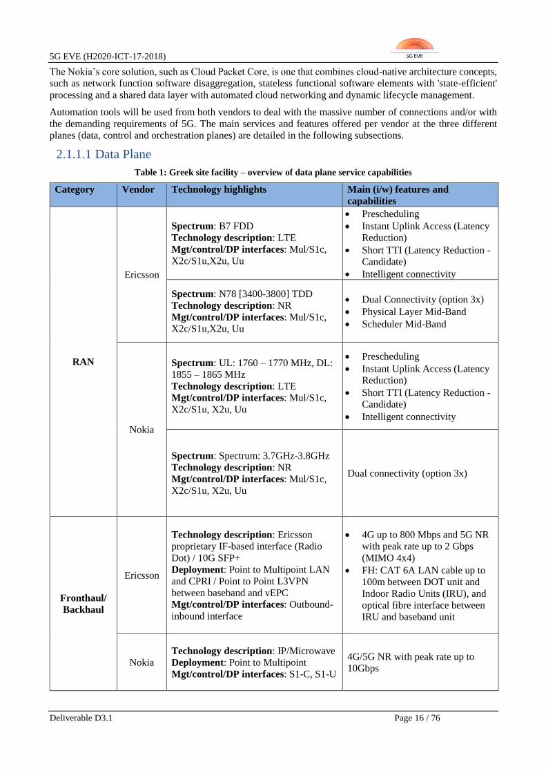
2.1.1.1 Data Plane
Table 1: Greek site facility – overview of data plane service capabilities
Category Vendor Technology highlights Main (i/w) features and
capabilities
RAN
Ericsson
Spectrum: B7 FDD
Technology description: LTE
Mgt/control/DP interfaces: Mul/S1c,
X2c/S1u,X2u, Uu
• Prescheduling
• Instant Uplink Access (Latency
Reduction)
• Short TTI (Latency Reduction -
Candidate)
• Intelligent connectivity
Spectrum: N78 [3400-3800] TDD
Technology description: NR
Mgt/control/DP interfaces: Mul/S1c,
X2c/S1u,X2u, Uu
• Dual Connectivity (option 3x)
• Physical Layer Mid-Band
• Scheduler Mid-Band
Nokia
Spectrum: UL: 1760 – 1770 MHz, DL:
1855 – 1865 MHz
Technology description: LTE
Mgt/control/DP interfaces: Mul/S1c,
X2c/S1u, X2u, Uu
• Prescheduling
• Instant Uplink Access (Latency
Reduction)
• Short TTI (Latency Reduction -
Candidate)
• Intelligent connectivity
Spectrum: Spectrum: 3.7GHz-3.8GHz
Technology description: NR
Mgt/control/DP interfaces: Mul/S1c,
X2c/S1u, X2u, Uu
Dual connectivity (option 3x)
Fronthaul/
Backhaul
Ericsson
Technology description: Ericsson
proprietary IF-based interface (Radio
Dot) / 10G SFP+
Deployment: Point to Multipoint LAN
and CPRI / Point to Point L3VPN
between baseband and vEPC
Mgt/control/DP interfaces: Outbound-
inbound interface
• 4G up to 800 Mbps and 5G NR
with peak rate up to 2 Gbps
(MIMO 4x4)
• FH: CAT 6A LAN cable up to
100m between DOT unit and
Indoor Radio Units (IRU), and
optical fibre interface between
IRU and baseband unit
Nokia
Technology description: IP/Microwave
Deployment: Point to Multipoint
Mgt/control/DP interfaces: S1-C, S1-U
4G/5G NR with peak rate up to
10Gbps

5G EVE (H2020-ICT-17-2018)
Deliverable D3.1 Page 17 / 76
Core
Ericsson
Technology description: 5G EPC
Mgt/control/DP interfaces: Si-C', Si-
U', S6a'
OpenvSwitch (OVS) DPDK or
single-root input/output
virtualization (SR-IOV) will be
used HW acceleration of User
plane
Nokia
Technology description: EPC/5G EPC
Deployment: R14 vEPC/R15 Core
Mgt/control/DP interfaces: S1-C/N2,
S1-U/N3, S6a/N12, SGi/N6
4G LTE/5GNR
Support of Option 3x
ME Hosts
Ericsson Not planned Not planned
Nokia Will be provided upon need Cloud
Cloud
Ericsson Technology description: Openstack Openstack distro for the 5G Core
deployment
Nokia
Technology description: Openstack
Capabilities and deployment: ETSI
NFV MANO
Mgt/control/DP interfaces: Nf-Vi, Or-
Vi, Vi-Vnfm, Or-Vnfm
• Openstack for 4G core
deployment
• Openstack for 5G core
deployment
PNFs
Ericsson
No PNFs planned
Nokia
Inter-site
connectivity
Ericsson
Standard IP connectivity and IP routing protocols will be used Nokia
2.1.1.2 Control Plane
Table 2: Greek site facility – overview of control plane service capabilities
Category Vendor Technology highlights Main (i/w) services and features
RAN
controller Ericsson
Sw tool(s): RAN control
signalling
• NR long or short PUCCH configuration:
Trade-off between fast HARQ feedback
and increasing signal quality reception. To
be decided during implementation.
• Semi-Dynamic NR slot configuration
enabled via RRC (Radio Resource
Signalling) signalling.
• LTE-NR Dual Connectivity (DC) Split-
DRB (Data Radio Bearer) flow control
mechanism used over the X2 interface
(X2-U) to keep buffers in the eNB filled at
the right level.

5G EVE (H2020-ICT-17-2018)
Deliverable D3.1 Page 18 / 76
Nokia Sw tool(s): RAN control
signalling
• NR long or short PUCCH configuration:
Trade-off between fast HARQ feedback
and increasing signal quality reception. To
be decided during implementation.
• Semi-Dynamic NR slot configuration
enabled via RRC (Radio Resource
Signalling) signalling.
• LTE-NR Dual Connectivity (DC) Split-
DRB (Data Radio Bearer) flow control
mechanism used over the X2 interface
(X2-U) to keep buffers in the eNB filled at
the right level.
SDN
controller
Ericsson Not planned Not planned
Nokia
ME Platform
Manager &
Orchestrator
Ericsson Not planned
Management and orchestration solution is
embedded in the CEE/VIM solution. No
additional layers provided.
Nokia Not planned
Management & orchestration solution is
embedded in the NOKIA CloudBand solution
[8]. No additional layers provided. Use of
ONAP orchestrator [10] will have to be agreed
for Greek site affected affiliates.
VIM
Ericsson
Sw tool(s): Openstack
Queens [6]
APIs: at least base
Openstack APIs and
components [6]
Ericsson VIM modules are in CEE
Nokia
Sw tool(s): CloudBand
Infrastructure Software
(CBIS) [8]
APIs: at least base
OpenStack APIs and
components [6]
Nokia VIM modules are provided by the CBIS
product
Additional
components
(e.g.
monitoring
platform,
inter-domain
SDN
controller,
etc.)
Ericsson To be further analysed To be further analysed
Nokia No additional components
will be provided No additional components will be provided
2.1.1.3 Orchestration Plane
5G EVE (H2020-ICT-17-2018)
Deliverable D3.1 Page 19 / 76
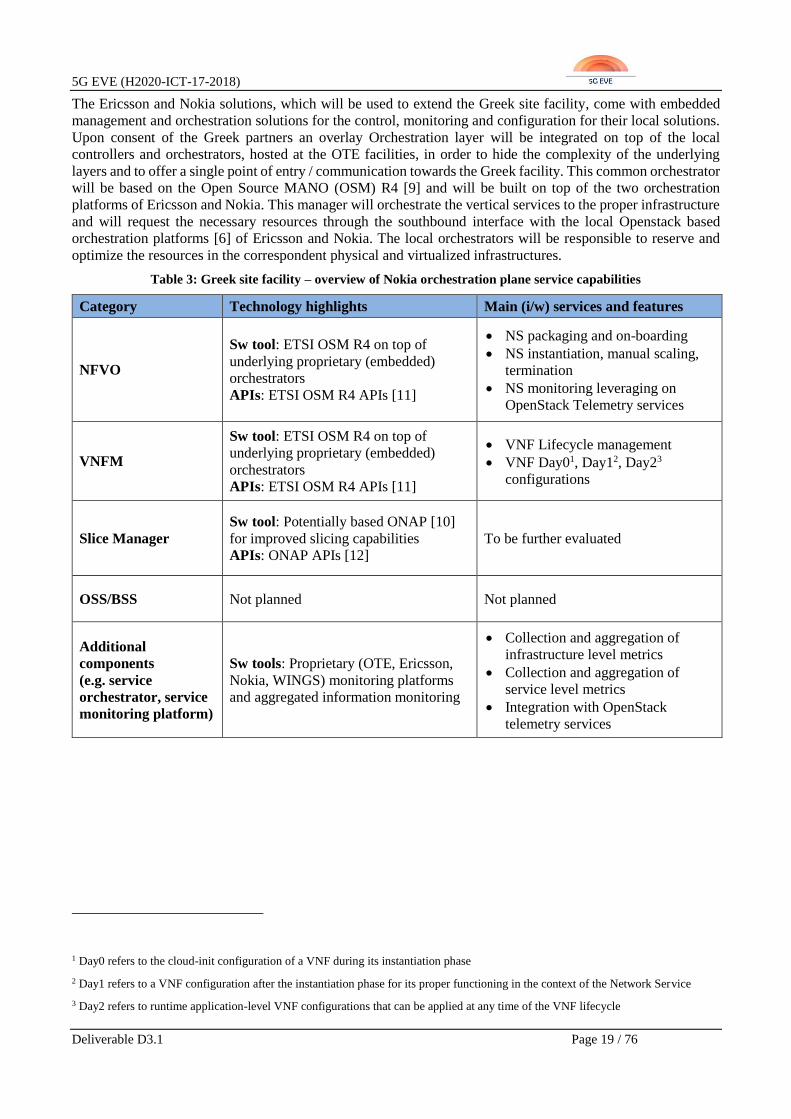
The Ericsson and Nokia solutions, which will be used to extend the Greek site facility, come with embedded
management and orchestration solutions for the control, monitoring and configuration for their local solutions.
Upon consent of the Greek partners an overlay Orchestration layer will be integrated on top of the local
controllers and orchestrators, hosted at the OTE facilities, in order to hide the complexity of the underlying
layers and to offer a single point of entry / communication towards the Greek facility. This common orchestrator
will be based on the Open Source MANO (OSM) R4 [9] and will be built on top of the two orchestration
platforms of Ericsson and Nokia. This manager will orchestrate the vertical services to the proper infrastructure
and will request the necessary resources through the southbound interface with the local Openstack based
orchestration platforms [6] of Ericsson and Nokia. The local orchestrators will be responsible to reserve and
optimize the resources in the correspondent physical and virtualized infrastructures.
Table 3: Greek site facility – overview of Nokia orchestration plane service capabilities
Category Technology highlights Main (i/w) services and features
NFVO
Sw tool: ETSI OSM R4 on top of
underlying proprietary (embedded)
orchestrators
APIs: ETSI OSM R4 APIs [11]
• NS packaging and on-boarding
• NS instantiation, manual scaling,
termination
• NS monitoring leveraging on
OpenStack Telemetry services
VNFM
Sw tool: ETSI OSM R4 on top of
underlying proprietary (embedded)
orchestrators
APIs: ETSI OSM R4 APIs [11]
• VNF Lifecycle management
• VNF Day01, Day12, Day23
configurations
Slice Manager
Sw tool: Potentially based ONAP [10]
for improved slicing capabilities
APIs: ONAP APIs [12]
To be further evaluated
OSS/BSS Not planned Not planned
Additional
components
(e.g. service
orchestrator, service
monitoring platform)
Sw tools: Proprietary (OTE, Ericsson,
Nokia, WINGS) monitoring platforms
and aggregated information monitoring
• Collection and aggregation of
infrastructure level metrics
• Collection and aggregation of
service level metrics
• Integration with OpenStack
telemetry services
1 Day0 refers to the cloud-init configuration of a VNF during its instantiation phase
2 Day1 refers to a VNF configuration after the instantiation phase for its proper functioning in the context of the Network Service
3 Day2 refers to runtime application-level VNF configurations that can be applied at any time of the VNF lifecycle
5G EVE (H2020-ICT-17-2018)
Deliverable D3.1 Page 20 / 76
2.2 Spanish site facility
2.2.1 Overview of site capabilities
5TONIC Open 5G Lab [13] was created in 2015 by Telefónica I+D and IMDEA Networks Institute with a clear
vision to create an open research and innovation ecosystem laboratory in which industry and academia come
together to boost technology and business innovative ventures. Currently, the 5TONIC laboratory is composed
of 10 members (Telefónica, IMDEA Networks, Ericsson, University Carlos III Madrid, Intel, CommScope,
Altran, Cohere Technologies, InterDigital and RedHat) and 5 collaborators (IFEMA, ASTI Robotics, Rohde &
Schwarz, Luz Wavelabs and Saguna Networks).
The 5TONIC laboratory includes a solid baseline of facilities, infrastructure and equipment to support advanced
experimentation in the 5G Virtual Network Function and Wireless Systems areas. It provides access to a
common infrastructure with specific-purpose hardware, to assist in experiments, trials and demonstrations with
particular 5G network technologies, as well as to commodity hardware, which allows a cost-effective approach
to configure different network topologies of variable size and capacity. The 5TONIC site is located at IMDEA
Networks premises in Leganés, in the Madrid metropolitan area, but it has access to other locations for the
support of different network functions and use cases.
Because 5TONIC is being composed of different members, it is necessary to distinguish 5TONIC as a whole
and the part that will be available to 5G EVE. The specific infrastructure allocated to 5G EVE is provided by
Ericsson, Telefónica, UC3M, IMDEA Networks and Nokia, as well as some other general common
infrastructure and services existing in the lab. Examples of these include the data centre infrastructure with the
racks for each 5TONIC member; the communications infrastructure; a vEPC provided by Ericsson to evolve to
Next Generation Core (NGC); LTE Radio Access infrastructure provided by Ericsson and CommScope to be
evolved to NR; and virtualization, processing and transport infrastructure.
For April 2019 it is planned to have two non-integrated network infrastructures, one of them based on the
network elements provided by Ericsson, UC3M, Telefónica, IMDEA Networks and Telcaria (plus 5TONIC
own infrastructure), and the other one based on Nokia provided network elements plus 5TONIC common
infrastructure. Specifically, it is planned the incorporation of new network elements and the evolution of the
existing ones along the project lifetime. Furthermore, a higher level of integration between the mobile network
and the orchestration infrastructure is to be expected.
As the testbed is planned to initially provide 5G services in Non-Standalone (NSA) option 3a fashion with dual
connectivity mode, it will be necessary to keep the LTE RAN operating in Band 7 in combination with an 5G
NR RAN. The additional improvements, which are expected to be achieved, are the evolution of 5TONIC
Communications Infrastructure towards a programmable (SDN-based) architectural framework, the update of
the orchestration platform for supporting multi-slicing and the incorporation of Distributed Cloud / Edge
capabilities.
The following subsections provide an overview of the main capabilities, in terms of services and features
exposed, planned for the Spanish site facility at the three main layers identified as relevant for the 5G EVE
interworking framework: data, control and orchestration planes. For each plane, the specific information table
is provided.

5G EVE (H2020-ICT-17-2018)
Deliverable D3.1 Page 21 / 76
2.2.2 Main services and features offered
2.2.2.1 Data Plane
Table 4: Spanish site facility – overview of data plane service capabilities
Category Technology details Supported features and capabilities
RAN
Spectrum: B7, B42 and B43
(potentially also B20). B1 and B2 with
LTE.
Technology description: 4G LTE, 5G
NR NSA, NB-IoT and CAT-M under
consideration.
Mgt/control/DP interfaces: S1
• Higher order modulation (256QAM
downlink, 64QAM uplink).
• Uplink prescheduling for latency
reduction
• 5G Plug-in Massive MIMO over
LTE TDD
• 5G NR NSA
FH/BH
Technology description: IP routing
based BH
Deployment: concrete Router model
still to be determined
Mgt/control/DP interfaces: CLI (SDN
under evaluation)
WAN connectivity for MEC module
Core
Technology description: Ericsson and
Nokia vEPC including PGW, PCRF and
MME
Deployment: Ericsson vEPC Release 14
and 5G NSA. Nokia vMEC supporting a
MCN17 with a MicroCoreNetwork for
LTE, plus a second 5G NSA.
Mgt/control/DP interfaces: CMON
• Supports 5G NSA (R 15)
• CUPS (proprietary solution)
• IoT (NB-IoT, CAT-M1)
ME Hosts
Technology description: Local
breakout solution based on distributed
cloud
Capabilities and deployment: includes
required hosts for running 5G EVE
Madrid's trials. Specific COTS server
models still to be determined.
SR-IOV
Cloud
Technology description: DELL servers
Capabilities and deployment: 3 high-
profile servers each with 8 cores @2.40
GHz, 128 GB for RAM, 8 10Gbps
optical Ethernet ports
Mgt/control/DP interfaces:
management interfaces based on
5TONIC communications infrastructure
(optical switches)
SR-IOV
5G EVE (H2020-ICT-17-2018)
Deliverable D3.1 Page 22 / 76
PNFs
Not planned in the first phase.
Second phase:
Technology description: SDN capable
routers for Wide Area Network (WAN)
emulation. Specific models and
capabilities to be determined.
To be further analyzed
Inter-site
connectivity
Technology description: VPN IPSec
Tunnels, GEANT based interconnection
available
One VPN Gateway, boundary for
control and data plane Networks.
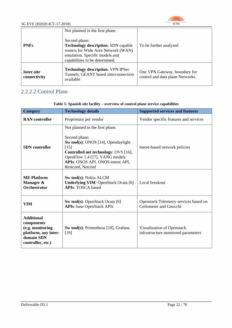
2.2.2.2 Control Plane
Table 5: Spanish site facility – overview of control plane service capabilities
Category Technology details Supported services and features
RAN controller Proprietary per vendor Vendor specific features and services
SDN controller
Not planned in the first phase.
Second phase:
Sw tool(s): ONOS [14], Opendaylight
[15]
Controlled net technology: OVS [16],
OpenFlow 1.4 [17], YANG models
APIs: ONOS API, ONOS-intent API,
Restconf, Netconf
Intent-based network policies
ME Platform
Manager &
Orchestrator
Sw tool(s): Nokia ALCM
Underlying VIM: OpenStack Ocata [6]
APIs: TOSCA based
Local breakout
VIM Sw tool(s): OpenStack Ocata [6]
APIs: base OpenStack APIs
Openstack Telemetry services based on
Ceilometer and Gnocchi
Additional
components
(e.g. monitoring
platform, any inter-
domain SDN
controller, etc.)
Sw tool(s): Prometheus [18], Grafana
[19]
Visualization of Openstack
infrastructure monitored parameters

5G EVE (H2020-ICT-17-2018)
Deliverable D3.1 Page 23 / 76
2.2.2.3 Orchestration Plane
Table 6: Spanish site facility – overview of orchestration plane service capabilities
Category Technology details Supported services and features
NFVO Sw tool: ETSI OSM R4 [9]
APIs: base OSM APIs [11]
• NS packaging and on-boarding
• NS instantiation, manual scaling,
termination
• Monitoring: module (MON)
VNFM Sw tool: ETSI OSM R4 [9]
APIs: base OSM APIs [11]
• VNF Lifecycle management
• VNF Day0, Day1, Day2
configurations
• Monitoring: module MON
Slice Manager
Not planned in the first phase:
Second phase:
Sw tool: integration between OSM and
ONOS intent-based API
APIs: OSM API, ONOS intent-based
API
OSM and ONOS integration for multi-
slicing support
OSS/BSS Ericsson proprietary OSS and
Telefonica Spain Lab HSS Provide synchronization signals
Additional
components (e.g.
any service
orchestrator or
service monitoring
platform)
Sw tool: Supervision tools based on
OSM Kafka Exporter
Collection and storage of infrastructure
and application monitoring metrics
Available VNFs /
MEC Apps / NSs
• ASTI PLC for AGVs control
• Nokia Multimedia VNF, KPIs VNF
and MCN17 VNF.
• ASTI VNF supports Industry 4.0 use
case.
• Nokia VNFs support UHF media use
case
2.3 French site facility
2.3.1 Overview of site capabilities
The French site facility is a federation of platforms that together build a hybrid cluster following TM Forum
recommendations. The utilized components are following diverse models: ETSI NFV reference model, Open
Platform for NFV (OPNFV) [20] recommendations (i.e. usage of Openstack as VIM, OSM or ONAP as
orchestrator, OAI for LTE components) and cloud-native principles [21]. The facility is comprised of two main
pillars:
• Pre-commercial Nokia 4G/5G end-to-end network facility, that is called “Nokia 5G innovation platform
for Vertical Markets” and is located in Paris-Saclay.
• Open-source building blocks that are distributed on several facilities interconnected by VPN, namely:
o Plug-in platform located in Paris (operated by Orange)

5G EVE (H2020-ICT-17-2018)
Deliverable D3.1 Page 24 / 76
o Flexible Netlab platform located in Rennes (operated by B-COM)
o OpenAir5G playground located in Sophia Antipolis (operated by Eurecom)
o End-to-end Mobile Networks Virtualization and Verification (Nokia Bell Labs).
Figure 2: French node architecture
The French facility partners will operate the whole cluster of building blocks as a distributed cloud enabling
common deployment and monitoring capabilities, while at the same time presenting a unified, single facility
image towards the rest of the 5G EVE facilities and the external third parties (vertical industries), as well. Each
cluster is composed of infrastructure pods provided by different facilities. In addition, the various components
are issued by the respective cluster partners and deployed in different pods according to their capabilities.
Figure 3: French site as a federation

5G EVE (H2020-ICT-17-2018)
Deliverable D3.1 Page 25 / 76
Some of these components and clusters have been a significant part of previous and ongoing 5G-PPP projects
(Superfluidity [22], NGPaaS [23], 5G Ensure [24], etc.) and are expected to be heavily reused in 5G EVE, taking
also into account any insights that have or will arise from these projects. As a general practice, DevOps and
slicing are key technologies from the aforementioned projects that will be leveraged during the 5G EVE end-
to-end facility development.
The focus of the facility development will fall on the following four main directions:
• End-to-end and network KPI validation
• Multi-domain interoperability
• New services on-boarding
• New experimental features and platforms
The aforementioned development goals will be achieved through the adoption and implementation of innovative
technologies such as M-MIMO, Cloud RAN (C-RAN) IoT, Cloud RAN 5G, Central Unit (CU)/Distributed Unit
(DU) split, SDN, NFV and MEC.
The following subsections summarize the main capabilities, services and features implemented and offered by
the French site facility and that are relevant for the 5G EVE interworking framework definition.
2.3.2 Main services and features offered
The French site facility as a federation of several sites, it is not expected to expose the data plane interfaces
between sites composing the French site. However, the control plane interfaces will be provided.
2.3.2.1 Data Plane
The data plane is split into the pre-commercial and open-source pillars.
Pre-commercial pillar
Concerning the pre-commercial pillar, the data plane is similar to that one described in D2.1 [2] and summarized
in Table 7.
Table 7: French site facility – overview of pre-commercial data plane service capabilities
Category Technology highlights Main (i/w) features and capabilities
RAN
Spectrum: 28 and 78
Technology description: 4G and 5G (R15 3.x)
Mgt/control/DP interfaces: X2-c and X2-u,
S1-U
• 4G & 5G RAN are virtualized using
Cloud RAN.
• Radio Unit supports all radio access
technologies including 4.9G, which
provides future service continuity
with 5G networks (extreme
capacity, massive connectivity and
ultra-low latency)
Fronthaul/
Backhaul
Technology description: Ethernet
Deployment: Commercial Switch
Mgt/control/DP interfaces: F1-c and F1-u
To be further analysed
Core
Technology description: R15 3.x
Deployment: VNF using Nokia VIM
Mgt/control/DP interfaces: S1-u
• Shared Data Layer
• Hyper Converged Infrastructure
(HCI) approach
5G EVE (H2020-ICT-17-2018)
Deliverable D3.1 Page 26 / 76
ME Hosts Not planned Not planned
Cloud
Technology description: Cloud RAN
infrastructure VIM
Mgt/control/DP interfaces: Cloud RAN
controller
CU infrastructure is based on Nokia
Airframe product using the Nokia Cloud
Infrastructure for Radio VNF hosting
PNFs Not planned Not planned
Inter-site
connectivity To be further investigated To be further investigated
Open-source pillar
Concerning the open-source pillar, it is not expected to provide data plane interfaces between the sites within
the French cluster.
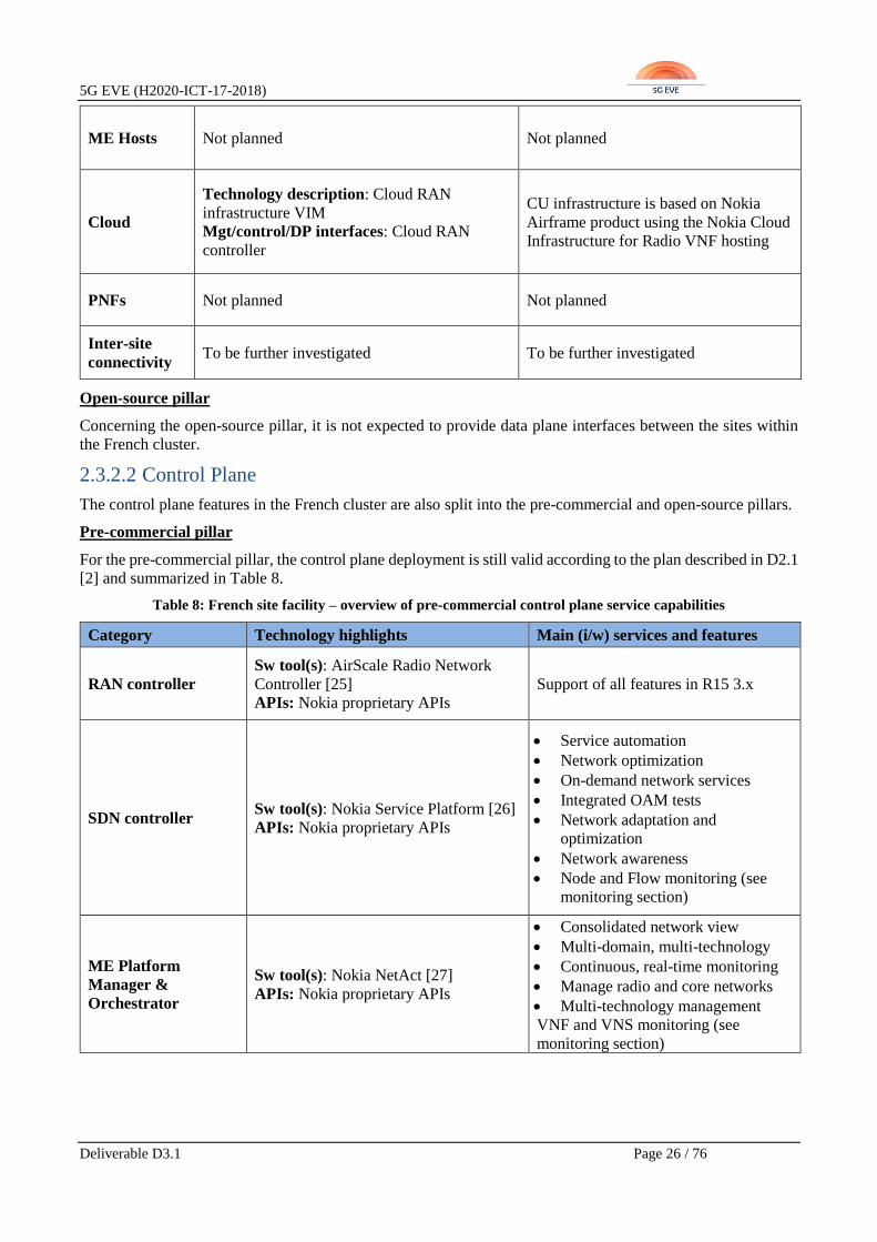
2.3.2.2 Control Plane
The control plane features in the French cluster are also split into the pre-commercial and open-source pillars.
Pre-commercial pillar
For the pre-commercial pillar, the control plane deployment is still valid according to the plan described in D2.1
[2] and summarized in Table 8.
Table 8: French site facility – overview of pre-commercial control plane service capabilities
Category Technology highlights Main (i/w) services and features
RAN controller
Sw tool(s): AirScale Radio Network
Controller [25] APIs: Nokia proprietary APIs
Support of all features in R15 3.x
SDN controller Sw tool(s): Nokia Service Platform [26]
APIs: Nokia proprietary APIs
• Service automation
• Network optimization
• On-demand network services
• Integrated OAM tests
• Network adaptation and
optimization
• Network awareness
• Node and Flow monitoring (see
monitoring section)
ME Platform
Manager &
Orchestrator
Sw tool(s): Nokia NetAct [27] APIs: Nokia proprietary APIs
• Consolidated network view
• Multi-domain, multi-technology
• Continuous, real-time monitoring
• Manage radio and core networks
• Multi-technology management
VNF and VNS monitoring (see
monitoring section)
5G EVE (H2020-ICT-17-2018)
Deliverable D3.1 Page 27 / 76
VIM
Sw tool(s): Nokia CBIS for virtualized
infrastructure management [8]
APIs: Openstack based APIs [6]
• Management of compute, storage,
and network resources
• It hosts VNFs and ensures that they
meet strict robustness,
performance, and security
requirements
• VNF and VNS monitoring (see
monitoring section)
Additional
components
(e.g. monitoring
platform, inter-
domain SDN
controller, etc.)
Wireless Network Guardian [28]
• End-to-end network analytics and
reporting
• Real time analytics tool
• Measure performance, detect
anomalies and report airtime
• Components will be monitored,
and the following functionalities
are provided:
o statistics collection
o alarms generation
o correction mechanisms
• Multivendor, multi-technology
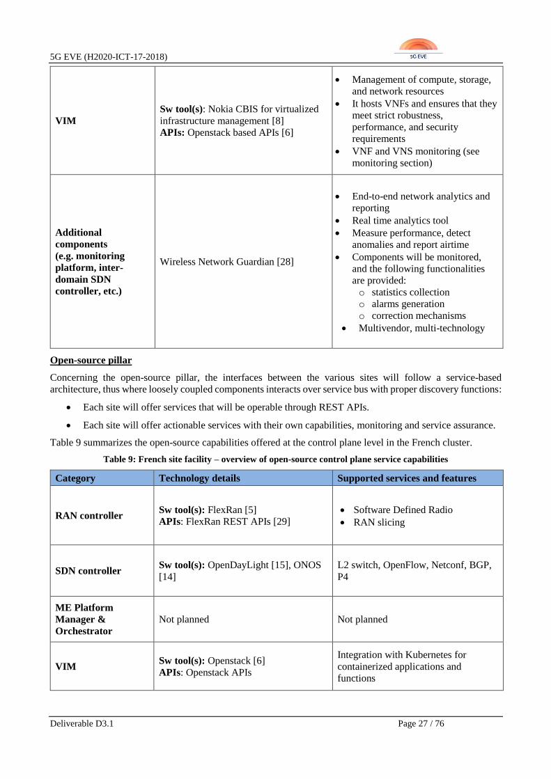
Open-source pillar
Concerning the open-source pillar, the interfaces between the various sites will follow a service-based
architecture, thus where loosely coupled components interacts over service bus with proper discovery functions:
• Each site will offer services that will be operable through REST APIs.
• Each site will offer actionable services with their own capabilities, monitoring and service assurance.
Table 9 summarizes the open-source capabilities offered at the control plane level in the French cluster.
Table 9: French site facility – overview of open-source control plane service capabilities
Category Technology details Supported services and features
RAN controller Sw tool(s): FlexRan [5]
APIs: FlexRan REST APIs [29]
• Software Defined Radio
• RAN slicing
SDN controller Sw tool(s): OpenDayLight [15], ONOS
[14]
L2 switch, OpenFlow, Netconf, BGP,
P4
ME Platform
Manager &
Orchestrator
Not planned Not planned
VIM Sw tool(s): Openstack [6]
APIs: Openstack APIs
Integration with Kubernetes for
containerized applications and
functions

5G EVE (H2020-ICT-17-2018)
Deliverable D3.1 Page 28 / 76
Additional
components
(e.g. monitoring
platform, inter-
domain SDN
controller, etc.)
To be further analyzed To be further analyzed
2.3.2.3 Orchestration plane
The orchestration plane is sub-divided into the pre-commercial and the open-source pillars.
Pre-commercial pillar
Concerning the pre-commercial pillar, the orchestration plane is similar to that one described in D2.1 [2] and
summarized in Table 10.
Table 10: French site facility – overview of pre-commercial orchestration plane service capabilities
Category Technology highlights Main (i/w) services and features
NFVO
Sw tool: Nokia CloudBand Network
Director [8]
APIs: ETSI NFV standards-based APIs
• Network service orchestration,
• Resource orchestration and
optimization.
VNFM
Sw tool: Nokia CloudBand Application
Manager [8]
APIs: ETSI NFV standards-based APIs
• Automated VNF lifecycle
management
• VNF configuration
• Integration with VIM for
virtualized resources provisioning
Slice Manager Not planned Not planned
OSS/BSS Not planned Not planned
Additional
components
(e.g. service
orchestrator, service
monitoring platform)
To be further analysed To be further analysed
Available VNFs /
MEC Apps / NSs To be further analysed To be further analysed
Open-source pillar
Concerning the pre-commercial pillar, the orchestration plane is similar to that one described in D2.1 [2] and
based on the following main assumptions:
• A “root” orchestration will be based on ONAP [10] and will control each elements of the federation.
• Each element will have its own orchestrator, such as Cloudify [30], Nokia CloudBand [8], NGPaaS [23]
(based on Kubernetes [31]) or others.
• Each orchestrator shall offer a “northbound” interface to the upper orchestration element.

5G EVE (H2020-ICT-17-2018)
Deliverable D3.1 Page 29 / 76
Table 11: French site facility – overview of open-source orchestration plane service capabilities
Category Technology details Supported services and features
NFVO Sw tool: ONAP [10]
APIs: ONAP REST APIs [12]
• NS lifecycle management (manual and
auto-scale)
• Fault and performance management,
• Catalogue features
• Multi cloud platform support
(Openstack, Kubernetes)
VNFM Sw tool: ONAP [10]
APIs: ONAP REST APIs [12]
• VNF lifecycle management, fault and
performance management
• Internal components:
▪ SDNC – network controller
▪ APPC – VNF controller,
▪ Multi VIM – infrastructure
manager
Slice Manager Sw tool: ONAP [10]
APIs: ONAP REST APIs [12]
Ongoing support for:
• slice lifecycle management
• multi-domain/multi-site slicing
capabilities
OSS/BSS Not planned Not planned
Additional
components
(e.g. any service
orchestrator or
service monitoring
platform)
• ONAP Data Collection Analytics
and Events [32]
• Prometheus [18], Grafana [19]
Collection and analysis of VNFs events
Available VNFs /
MEC Apps / NSs vCPE, vFirewall, vIMS
2.4 Italian site facility
2.4.1 Overview of site capabilities
The 5G EVE Italian site facility is hosted in the city of Turin, where all 5G components will be deployed from
the radio elements to the distributed cloud PoPs with NFV capabilities, as an integration of lab-based and
operational infrastructures. Note that a part of the 5G site facility in Turin is based on existing (and planned)
deployments in the context of the “Torino 5G” initiative, where some of the 5G EVE partners are participating.
All of the 5G EVE Italian partners participate with different contributions to the deployment of the Turin site
facility infrastructure components, software tools, services and applications that will serve to validate the
vertical services and requirements related to at least the following two use cases [1]:
• Smart Transport: Intelligent railway for smart mobility (see section 3.1.1)
• Smart Cities: Safety and Environment - Smart Turin (see section 3.1.5)
The Turin site facility will encompass 5G network elements including NR Access and 5G Core functionalities,
provided by Ericsson and deployed into TIM lab testing infrastructures and field operational networks.
Additional testing facilities are also planned to be deployed by CNIT in the area of Politecnico di Torino,
including 5G radio elements and an NFVI PoP. In summary, mobile radio access in the Italian site facility will

5G EVE (H2020-ICT-17-2018)
Deliverable D3.1 Page 30 / 76
range from wireless networks based on 5G standards (3GPP R15_Option 3x, as initial deployment) down to 4G
LTE for preliminary validations and benchmarking, as well as local WiFi networks and NB-IoT for indoor
deployments and specific connectivity with IoT devices.
On top of this comprehensive physical infrastructure, the Italian site facility will include SDN/NFV based
control and orchestration tools aiming at coordinating the deployment of VNFs, Network Services and network
slices, thus matching the vertical requirements in terms of performance, availability and reliability. Through
these control and orchestration tools, vertical-tailored and application-specific VNFs and functions in general
will be deployed in support of the Smart Transport (e.g. for media streaming, traffic flows and user pattern
analysis) and Smart Turin (e.g. for integration of IoT sensors and devices with the oneM2M [33] platform by
TIM) use-cases.
The following subsections provide an overview of the main capabilities, in terms of services and features
exposed, planned for the Italian site facility at the data, control and orchestration planes. For each plane, a
dedicated subsection is provided.
2.4.2 Main services and features offered
2.4.2.1 Data Plane
Table 12: Italian site facility – overview of data plane service capabilities
Category Technology highlights Main (i/w) features and capabilities
RAN
Spectrum: B43
Technology description: 5G New
radio non-standalone (NSA)
Mgt/control/DP interfaces: S1/X2
New radio connectivity towards LTE
signalling
Fronthaul/
Backhaul
Technology description:
• FH - Active functionality of
Transponders and Power
Monitoring Units and built on
the DWDM platform
• BH – High capacity aggregation
router
Deployment:
• FH - High density pizza box for
indoor unit (for Baseband or
RRU connection) and outdoor
equipment unit (for RRU
connection)
• BH – Provides Radio aware
transport for mobile backhaul
with high 10GE density and
100GE switching capacity
Mgt/control/DP interfaces:
• FH - IPv4/IPv6 manageability
by LCT/CLI and ENM
• BH – Managed by CLI, ENM,
NETCONF and Yang model
• FH - The Fronthaul active solution
provides high capacity and low
latency to ensure that even the most
stringent transport requirements of
LTE, LTE-advanced and 5G are
met.
• BH - Provides application aware
traffic engineering with open and
standardized interfaces, enabling
network slicing and ability to tailor
services for utmost agility

5G EVE (H2020-ICT-17-2018)
Deliverable D3.1 Page 31 / 76
Core
Technology description:
Distributed cloud (3GPPP)
Mgt/control/DP interfaces:
logical between different VMs and
only physical connections will be
towards the RAN (eNB and gNB)
and towards the backhaul (switch)
SR-IOV accelerator
ME Hosts
Technology description: DELL
servers
Capabilities and deployment:
Multi-server without external
storage
Mgt/control/DP interfaces: Extreme
switch as external host
SR-IOV accelerator
Cloud
Technology description: Ericsson
Execution environment (CEE)
Capabilities and deployment:
based on Mirantis Openstack
Mgt/control/DP interfaces: interface
with external control and traffic switch
SR-IOV accelerator
PNFs Not planned Not planned
inter-site connectivity Technology description: IPSec/GRE
VPN tunnelling
Two dedicated VPN gateways at the
boundary of the control/orchestration
and data plane intra-site networks
2.4.2.2 Control Plane
Table 13: Italian site facility – overview of control plane service capabilities
Category Technology highlights Main (i/w) services and features
RAN controller
Sw tool(s): Ericsson Network Manager
(ENM)
APIs: Ericsson’s proprietary
• Configuration of radio elements
• Seamless integration with
configuration and management of
other segments (transport, core)
SDN controller Sw tool: OpenDaylight [15]
APIs: OpenDaylight base APIs
Base Opendaylight
Beryllium/Nitrogen version features,
applications and services.

5G EVE (H2020-ICT-17-2018)
Deliverable D3.1 Page 32 / 76
Sw tools: Ericsson ENM/NorthStar [34]
API: NorthStar REST API
• Network Optimization
• Predictable Deterministic Network
State
• Multiple User-Defined Constraints,
Global network view
• Ordering and Synchronization of
Paths
ME Platform
Manager &
Orchestrator
Sw tool(s): Ericsson orchestrator as
manager of the distributed edge/core
cloud deployment
Underlying VIM: OpenStack Queens
APIs: Ericsson’s API only for network
nodes
• Edge breakouts
• Redirection of traffic flows to local
edge applications
VIM
Sw tool(s): OpenStack Queens; in
Ericsson VIM modules are in CEE
APIs: at least base OpenStack APIs and
components
• Management of virtualized
infrastructure resources
• Integration of network, compute,
storage Openstack components
Additional
components
Sw tool(s): Openstack Telemetry
APIs: Openstack APIs
Virtualized infrastructure metrics,
resource consumption monitoring and
events collection
2.4.2.3 Orchestration Plane
Table 14: Italian site facility – overview of orchestration plane service capabilities
Category Technology highlights Main (i/w) services and features
NFVO
Sw tool: Ericsson Orchestrator
APIs: Ericsson proprietary – ETSI NFV
SOL002 – SOL005 [35] (planned 2019)
• NS lifecycle management
• NS Descriptor-driven orchestration
• Tosca support for NS Description
Sw tool: OSM R4 [11]
APIs: ETSI NFV SOL005 as
northbound APIs [35]
• NS packaging and on-boarding
• NS instantiation, manual scaling,
termination
• NS monitoring leveraging on
OpenStack Telemetry services
• VNF Day0, Day1, Day2
configurations
VNFM
Sw tool: ENM – Ericsson Network
Manager for Ericsson PNFs and VNFs
APIs: Ericsson proprietary
VNF lifecycle management for
Ericsson’s PNFs and VNFs
(instantiate, terminate, scale, heal)

5G EVE (H2020-ICT-17-2018)
Deliverable D3.1 Page 33 / 76
Sw tool Ericsson Orchestrator for
generic VNF
APIs: Ericsson proprietary
• Generic VNFM for multivendor
VNFs
• VNF LifeCycle Management
• Integration with multi-vendor EMS
Slice Manager
Sw tool: Ericsson Service Orchestration
APIs: Ericsson proprietary
• Network Slice design
• (BluePrint Design, BluePrint
Validation)
• Network Slice instantiation (VNF
Instantiation, Network
Infrastructure configuration,
Network Elements integration)
• Network Slice operation (Network
Slice re-configuration, Supervision
and Performance, Network Slice
Scaling and Upgrade)
• Network Slice termination (De
Activation, Re-set configuration)
Sw tool: Nextworks’ Slicer (open-
source) [36]
APIs: REST APIs (non-standard)
• Vertical services lifecycle
management and provisioning
• Network slice management
functions
OSS/BSS Sw tool ENM- Ericsson network
manager
• High capacity and fully scalable
• Auto-Provisioning
• Enhanced CLI – Scripting for
massive automation
• Optimized RAN upgrades times
Additional
components
Sw tool: Ericsson Fault & Performance
Management
• Fault and Alarm collection and
correlation
• Alarm enrichment with tenant data
• Performance Management
Sw tool: Prometheus
• Collection and aggregation of
service level metrics
• Integration with OpenStack
telemetry services
Available VNFs /
MEC Apps / NSs vEPC, vSGSN-MME, vHSS, vCUDB

5G EVE (H2020-ICT-17-2018)
Deliverable D3.1 Page 34 / 76
3 Technical interworking requirements from vertical use cases
This section aims at providing a set of technical interworking requirements that derive from the vertical use
cases of 5G EVE. In particular, starting from the use cases described in deliverable D1.1 [1], and their general
and specific requirements, more technical requirements related to their deployment and execution are identified,
thus affecting the overall 5G EVE platform, and in the specific case of this document, the 5G EVE interworking
framework.
3.1 5G EVE Use Case technical requirements
The whole set of vertical use cases requirements listed in D1.1 [1] have been analysed against each use case
scenario, and as a result, a list of functional requirements has been identified.
The following sections provide a set of technical requirements for each of the 5G EVE vertical use cases with
the aim of highlighting those related to the interworking framework at different phases of the use case execution,
from deployment to operation and monitoring/analysis. It is relevant to highlight that these requirements refer
to the current definition and planned roadmap of each use case, as defined in D1.1 [1]. Any further elaboration,
improvement or update will depend on each 5G EVE use case evolution and will be reported in future WP3
deliverables, if required and applicable.
The vertical-oriented technical requirements listed in the following sections are grouped as follows:
• Deployment Requirements: all those aspects and features needed to deploy and provision the vertical
use case in the 5G EVE end-to-end facility;
• Runtime Requirements: runtime operations required to be supported in order to execute the vertical use
case;
• Monitoring/Analysis Requirements: monitoring and data analysis aspects in support of testing and
validation of the vertical use case experiments and targeted KPIs.
For each identified requirement, one of the following priorities is assigned:
• High: when the requirement is essential to execute and validate the given vertical use case, and therefore
it shall be satisfied;
• Medium: when the requirement validates a core concept of the vertical use case, and therefore it should
be satisfied;
• Low: when the requirement is related to nice-to-have features and properties of the given vertical use
case, and it does not affect the overall execution and validation of its concepts.
3.1.1 Smart Transport: Intelligent railway for smart mobility
The Smart Transport [1] use-case aims at exploiting the 5G network capabilities for improving railway
transportation services in two main directions. First, the use case intends to leverage on the expected 5G
performances to allow railway transport operators to provide new enhanced on-board train services for
passengers. Second, the use case plans to monitor in real time the passengers’ mobility patterns, thus enhancing
the railway and train management systems and improving the railway traffic management. This is achieved with
prediction of traffic peaks and bottlenecks in the public transportation, possibly by supporting urban
multimodality between railway networks and other transportation services.
Therefore, the Smart Transport use case is composed of two highly combined scenarios: i) 5G on-board media
content provisioning, to deliver Full HD and 4K media streaming services for entertainment and infotainment
of train passengers, and ii) Urban Mobility 5G data flows analysis and monitoring, where mobility data from
different transport operations is integrated towards an automatic identification of passengers’ mobility patterns,

5G EVE (H2020-ICT-17-2018)
Deliverable D3.1 Page 35 / 76
thus enabling enhancements of transportation planning and context-aware provisioning of info-mobility
services.
The two scenarios of the Smart Transport use case themselves do not have any specific requirement for being
deployed and executed across multiple sites, as they are planned to run and be validated in the Italian site facility.
However, the specific nature of both Smart Transport use case scenarios poses a set of technical requirements
to be addressed. These requirements are grouped in deployment, runtime and monitoring/analysis requirements,
as listed in the following tables.
Table 15: Smart Transport Use Case: deployment technical requirements
Deployment
requirements Priority Description
Concurrent slices
provisioning High
The Smart Transport use case requires that two concurrent
uRLLC (ultra-Reliable Low Latency Communication) and
mMTC (massive Machine Type Communication) slices are
deployed in parallel to serve the two scenarios for 5G on-board
media content provisioning and urban mobility 5G data flows
analysis and monitoring.
Slice network domains High The Smart Transport use case requires slices that span across
RAN, distributed edge and core segments.
Placement of slice
vertical VNFs High
In the 5G on-board media content provisioning scenario, the
media related VNFs (e.g. vCaches, video content servers)
require to be deployed at specific locations across edge and core
sides to fulfil the low latency requirements of the use case.
Placement of slice
monitors and data
analysis VNFs
High
In the Urban Mobility 5G data flows analysis and monitoring
scenario, monitors and data analysis VNFs have to be deployed
in specific MEC, edge and core locations to exploit proximity to
public transport passengers and apply distributed info mobility
data analysis.
Table 16: Smart Transport Use Case: runtime technical requirements
Runtime
requirements Priority Description
Dynamic re-placement
of vertical VNFs Medium
In the 5G on-board media content provisioning scenario, due to
the fast mobility of high-speed train passengers, the vertical
media-related VNFs (e.g. vCaches) may need to be dynamically
(or predictively) re-located to minimize the effects of the
handovers.
RAN configuration Medium
Runtime RAN configurations are required to maintain video
streaming continuity for high speed trains passengers in the 5G
on-board media content provisioning scenario, as well as to
enable user position measurement and processing at edge
locations in the urban mobility 5G data flows analysis and
monitoring scenario.

5G EVE (H2020-ICT-17-2018)
Deliverable D3.1 Page 36 / 76
Table 17: Smart Transport Use Case: monitoring/analysis technical requirements
Monitoring/Analysis
requirements Priority Description
5G network
performance
monitoring
High
5G network performance measurements, including per-device
delivered bandwidth, are required to be collected to validate the
requirement fixed to achieve from 5 to 20 Mbps throughput per
passenger.
Service performance
monitoring Medium
In the 5G on-board media content provisioning scenario, video
streaming metrics and performance measurements have to be
collected for estimating per-passenger quality of experience.
User mobility
monitoring Medium
In the Urban Mobility 5G data flows analysis and monitoring
scenario, the user position is required to be measured precisely
and monitored through 5G/MEC location services possibly
integrated with device Global Navigation Satellite Systems.
Emulation of high
density train
passengers (UEs)
High
In the 5G on-board media content provisioning scenario, the
emulation of a realistic scenario with 300 train passengers is
required through software tools that are able to emulate the
consumption of video Streaming Service in 4K/Full HD and
realize active measurements of 5G network performance.
3.1.2 Smart Tourism: Augmented Fair experience
Tourism activity must be considered a vast transversal industry involving a wide range of multiple providers
and users which configure and determine its unique idiosyncrasies. This diversity obliges to conscientiously
concrete the potential use cases participating in 5G EVE projects to obtain real validation resulting from access
to early state-of-the-art 5G features that can transform and improve the tourism sector globally.
The use case proposed for the smart tourism is the Augmented Fair, which aims at transforming the experience
of Trade Fair events’ users (exhibitors and visitors), with the objective of improving their interactions
(information sharing, discussion, networking, negotiations and transactions) by leveraging Virtual Reality
(VR)/Augmented Reality (AR) and 5G technologies. The main features encompassed in the Augmented Fair
service are interaction with holographic maps, augmented booth and interactive holographic communications.
Exhibitors may design virtual booths, with a variety of contents and experiences for interacting with their
various types and profiles of visitors over a mixed reality layer, also able to incorporate, whenever needed, 3D
volumetric presence of remotely located third persons and objects, as well as real-time translation services for
making voice communications more effective between speakers of a variety of languages. All interactions and
info exchanged through this platform shall also be available through digital means after the event to both
exhibitor and visitor.
Business oriented smart tourism is a large vertical industry which can be greatly enhanced using the 5G
capabilities to reduce operating expenses (OPEX) and to increase revenue through innovative services. The
following two sub-uses cases, which are described in D1.1 [1], have been identified:
• Sub-use case 1: AR Interaction
• Sub-use case 2: Business Augmented Booth
For demonstrating the Smart Tourism use case, we propose the following architecture:
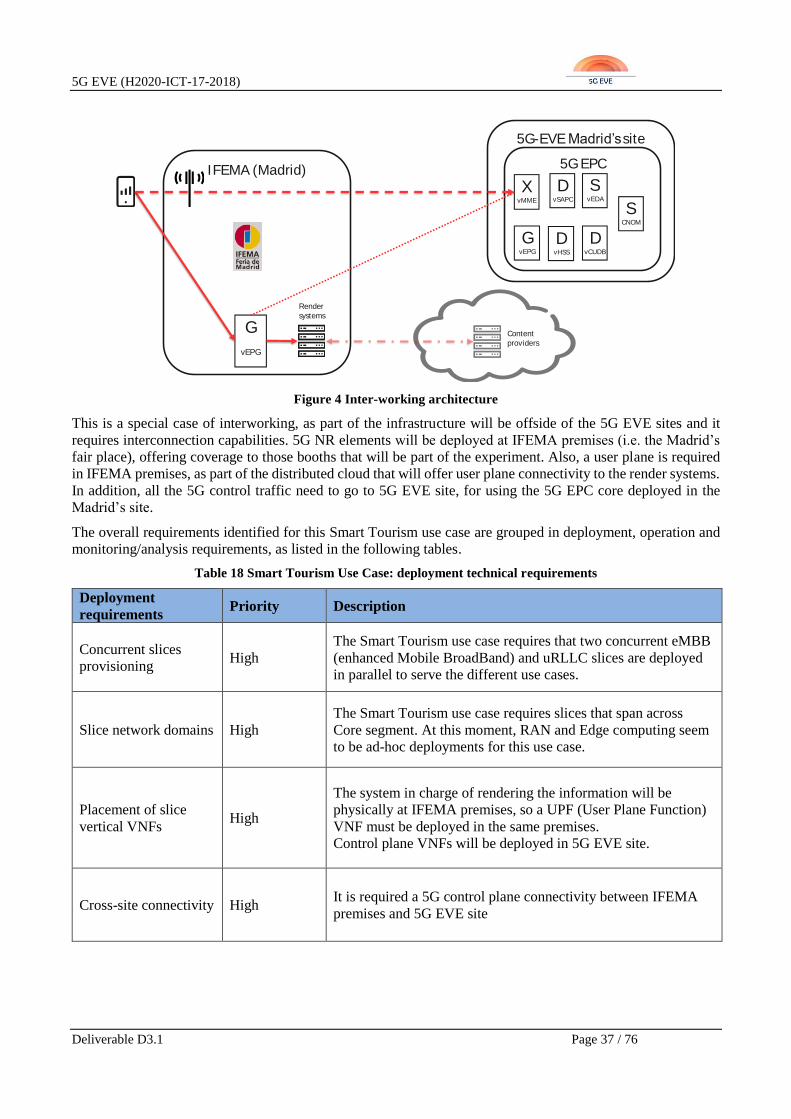
5G EVE (H2020-ICT-17-2018)
Deliverable D3.1 Page 37 / 76
Figure 4 Inter-working architecture
This is a special case of interworking, as part of the infrastructure will be offside of the 5G EVE sites and it
requires interconnection capabilities. 5G NR elements will be deployed at IFEMA premises (i.e. the Madrid’s
fair place), offering coverage to those booths that will be part of the experiment. Also, a user plane is required
in IFEMA premises, as part of the distributed cloud that will offer user plane connectivity to the render systems.
In addition, all the 5G control traffic need to go to 5G EVE site, for using the 5G EPC core deployed in the
Madrid’s site.
The overall requirements identified for this Smart Tourism use case are grouped in deployment, operation and
monitoring/analysis requirements, as listed in the following tables.
Table 18 Smart Tourism Use Case: deployment technical requirements
Deployment
requirements Priority Description
Concurrent slices
provisioning High
The Smart Tourism use case requires that two concurrent eMBB
(enhanced Mobile BroadBand) and uRLLC slices are deployed
in parallel to serve the different use cases.
Slice network domains High
The Smart Tourism use case requires slices that span across
Core segment. At this moment, RAN and Edge computing seem
to be ad-hoc deployments for this use case.
Placement of slice
vertical VNFs High
The system in charge of rendering the information will be
physically at IFEMA premises, so a UPF (User Plane Function)
VNF must be deployed in the same premises.
Control plane VNFs will be deployed in 5G EVE site.
Cross-site connectivity High It is required a 5G control plane connectivity between IFEMA
premises and 5G EVE site
5G-EVEMadrid’ssite
IFEMA (Madrid)
G
vEPG
5G EPC
GvEPG
XvMME
DvSAPC
DvHSS
DvCUDB
SvEDA
SCNOM
Render
systems
Content
providers

5G EVE (H2020-ICT-17-2018)
Deliverable D3.1 Page 38 / 76
Table 19: Smart Tourism Use Case: monitoring/analysis technical requirements
Monitoring/Analysis
requirements Priority Description
5G network
performance
monitoring
High
5G network performance measurements, including per-device
delivered bandwidth, are required to be collected to validate the
vertical requirements for density and peak throughput per user.
3.1.3 Industry 4.0: Autonomous vehicles in manufacturing environments
The Industry 4.0 use cases regarding the operation of autonomous vehicles in manufacturing environments are
among the most challenging ones being realized within the 5G EVE project, since ultra-Reliable Low-Latency
Communication (uRLLC) capabilities have to be demonstrated with extreme low latency requirements for
AGV. This use case will be demonstrated both in the Greek and the Spanish site facilities and detailed
requirements regarding the execution of these use cases have been provided in deliverable D1.1 of 5G EVE [1],
including an advanced requirements analysis and providing additional insight into their inherent challenges.
During the pilot execution, various features of autonomous vehicle operation will be demonstrated, with varied
levels of difficulty in terms of implementation and with different requirements. The most prominent features
based on the scenario description using AGVs [1] of the two sites are:
• Autonomous vehicle navigation based on on-board (and potentially other) sensors;
• Obstacle avoidance and route adjustment based on moving obstacles;
• Transportation of goods between specific points with free movements of the AGV in space;
• Autonomous driving to charging station;
• Remote progress monitoring through mounted High Dynamic Range (HDR) cameras;
• Remote navigation through HD navigation camera & image processing.
All these features will be demonstrated in a local setting by utilizing resources of the respective local testbed
(Greek or Spanish facility) and other potential local sources of information, such as facility mounted sensors (at
least at a first stage), due to the nature of these pilots (AGV operation in specific manufacturing environments).
Depending on specific interests from verticals, at a later stage, the last two features listed above (i.e. remote
monitoring and remote navigation) could also be demonstrated in a multi-site deployment showcasing the
interworking capabilities of the 5G EVE end-to-end facility. In such a scenario, a remote user in a different 5G
EVE site could monitor the progress of the AGV operations taking place in another facility or even remotely
controlling the movements (or giving orders) to the AGV.
Table 20: Industry 4.0 Use Case: deployment technical requirements
Deployment
requirements Priority Description
Concurrent slices
provisioning N/A
The Industry 4.0 use cases concurrent slices provisioning:
URLLC slice for AVG controller and eMBB slice for
uninterrupted HD video streaming to be used in the monitoring
or remote controlling cases.
Slice network domains High The Industry 4.0 use cases require slices that span distributed
edge and Core segments.

5G EVE (H2020-ICT-17-2018)
Deliverable D3.1 Page 39 / 76
Placement of slice
vertical VNFs High
The Industry 4.0 use cases deploy a virtual controller for the
AGVs with a critical requirement of RTT (less than 10 ms), so it
should be deployed at the edge computing environment. Other
VNFs can be deployed at core (or in a public cloud).
Placement of slice
monitors and data
analysis VNFs
High ASTI use case deploys a monitor VNF near the virtual controller
(edge computing environment).
Cross-site connectivity Medium
ASTI use case can be used for demonstrating the interworking
capabilities of 5G EVE. Thus, it requires a control and
orchestration interconnectivity between Madrid and Turin sites
to enable either remote control or monitoring of AGVs.
Table 21: Industry 4.0 Use Case: operation technical requirements
Runtime
requirements Priority Description
Background traffic
generator Medium
In order to check the density requirement, Industry 4.0 ASTI use
case requires to simulate the traffic of at least 400 AGVs.
Table 22: Industry 4.0 Use Case: monitoring/analysis technical requirements
Monitoring/Analysis
requirements Priority Description
5G network
performance
monitoring
High
5G network performance measurements, including service
latency, are required to be collected to validate the requirement
of 10 ms RTT.
Service performance
monitoring High
Service performance measurements, including service metrics,
are required to validate the use cases (correction measurements,
AGV power consumption).
3.1.4 Smart Energy: Fault Management for distributed electricity generation in
smart grids
The utilities sector comprises multiple society-critical industries such as water, electricity and gas, making the
impact of 5G connectivity on their distribution networks, as well as the resulting increased safety, efficiency,
reliability and reduced capital expenditures (CAPEX) and OPEX, of extreme societal importance.
The integration of an ever-increasing number of Distributed Generators (DGs), e.g. renewable energy, farms,
households, into the electricity grid also introduces greater unpredictability of energy production and an
increased risk of failures and section isolations (i.e., islanding). To mitigate these effects, ultra-reliable and
ultra-fast fault detection and management is necessary to increase network stability and provide system
protection. Currently, fault detection and management in energy grids takes place through fiber connectivity

5G EVE (H2020-ICT-17-2018)
Deliverable D3.1 Page 40 / 76
among the centralized electricity generation points (e.g., power plants). The shift towards DG offers great
potential, but also makes a fiber communication monitoring solution prohibitive due to its deployment cost.
However, 5G can enable ultra-fast and ultra-reliable fault detection and management in high-scale deployments,
i.e. with extensive number of DGs. Such a fault management system is a key requirement for modern and next
generation smart grids, as it allows to implement immediate automated reaction to changes in the network, while
avoiding islanding and isolation of smart grid portions. The use of smart metering and fault detection
mechanisms in combination with edge computing features for ultra-fast processing can therefore substantially
improve and automate the level of control over the energy grid.
The Smart Energy use case in 5G EVE is implemented in two different scenarios, one in the Greek and the other
in the French site facility, as reported in D1.1 [1]. The Greek scenario focuses on fault prediction, fault
management and network restoration in a smart grid 5G deployment composed of a network of distributed
energy sources equipped with 5G enabled smart sensors to measure the energy level, connected to a network of
distributed energy consumers equipped with 5G enabled sensors to measure the energy consumption. The
French scenario, on the other hand, focuses on a smart grid protection schemes for remote decoupling of DGs
through 5G enabling ultra-low latency communication among the hierarchically distributed primary and
secondary protections.
For both use cases, a set of additional requirements have been identified by processing the scenarios and
requirements in D1.1 [1]. These requirements have to be addressed by the 5G EVE platform and are grouped in
deployment, runtime and monitoring/analysis requirements, as follows:
Table 23: Smart Energy Use Case: deployment technical requirements
Deployment
requirements Priority Description
Single slice
provisioning High
The Smart Energy use case requires a single uRLLC slice,
augmented with mMTC capabilities, to be deployed for its
execution.
Slice network domains High The Smart Energy use case requires slices that span across RAN,
MEC and Core segments.
Device-to-device
connectivity High
The Smart Energy slice requires device-to-device connectivity
for enabling communications between the grid protections, the
feeders and the substations with ultra-low latency.
Placement of slice
vertical VNFs High
The Smart Energy fault detection, fault management and
network restoration VNFs require to be deployed at specific
edge locations to fulfil the ultra-low latency requirements of the
use case.
Table 24: Smart Energy Use Case: monitoring/analysis technical requirements
Monitoring/Analysis
requirements Priority Description
5G network
performance
monitoring
High
5G network performance measurements, including device-to-
device latency, are required to be collected to validate the
requirement of 5ms maximum latency.
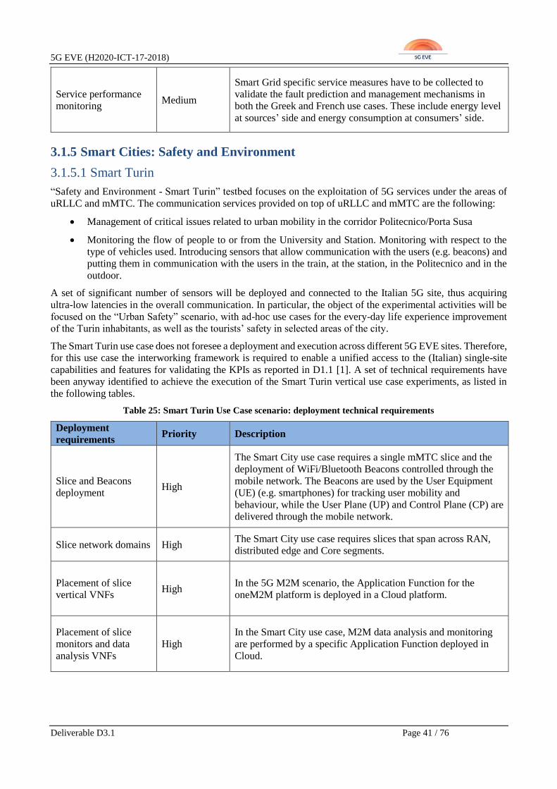
5G EVE (H2020-ICT-17-2018)
Deliverable D3.1 Page 41 / 76
Service performance
monitoring Medium
Smart Grid specific service measures have to be collected to
validate the fault prediction and management mechanisms in
both the Greek and French use cases. These include energy level
at sources’ side and energy consumption at consumers’ side.
3.1.5 Smart Cities: Safety and Environment
3.1.5.1 Smart Turin
“Safety and Environment - Smart Turin” testbed focuses on the exploitation of 5G services under the areas of
uRLLC and mMTC. The communication services provided on top of uRLLC and mMTC are the following:
• Management of critical issues related to urban mobility in the corridor Politecnico/Porta Susa
• Monitoring the flow of people to or from the University and Station. Monitoring with respect to the
type of vehicles used. Introducing sensors that allow communication with the users (e.g. beacons) and
putting them in communication with the users in the train, at the station, in the Politecnico and in the
outdoor.
A set of significant number of sensors will be deployed and connected to the Italian 5G site, thus acquiring
ultra-low latencies in the overall communication. In particular, the object of the experimental activities will be
focused on the “Urban Safety” scenario, with ad-hoc use cases for the every-day life experience improvement
of the Turin inhabitants, as well as the tourists’ safety in selected areas of the city.
The Smart Turin use case does not foresee a deployment and execution across different 5G EVE sites. Therefore,
for this use case the interworking framework is required to enable a unified access to the (Italian) single-site
capabilities and features for validating the KPIs as reported in D1.1 [1]. A set of technical requirements have
been anyway identified to achieve the execution of the Smart Turin vertical use case experiments, as listed in
the following tables.
Table 25: Smart Turin Use Case scenario: deployment technical requirements
Deployment
requirements Priority Description
Slice and Beacons
deployment High
The Smart City use case requires a single mMTC slice and the
deployment of WiFi/Bluetooth Beacons controlled through the
mobile network. The Beacons are used by the User Equipment
(UE) (e.g. smartphones) for tracking user mobility and
behaviour, while the User Plane (UP) and Control Plane (CP) are
delivered through the mobile network.
Slice network domains High The Smart City use case requires slices that span across RAN,
distributed edge and Core segments.
Placement of slice
vertical VNFs High
In the 5G M2M scenario, the Application Function for the
oneM2M platform is deployed in a Cloud platform.
Placement of slice
monitors and data
analysis VNFs
High
In the Smart City use case, M2M data analysis and monitoring
are performed by a specific Application Function deployed in
Cloud.
5G EVE (H2020-ICT-17-2018)
Deliverable D3.1 Page 42 / 76
Table 26 Smart Turin Use Case scenario: Runtime technical requirements
Runtime
requirements Priority Description
WiFi/Bluetooth
Beacons High
WiFi/Bluetooth Beacons and 5G/NB-IoT (Narrow Band IoT)
mobile networks have to be coordinated for the user data
collection.
Table 27: Smart Turin Use Case scenario: monitoring/analysis technical requirements
Monitoring/Analysis
requirements Priority Description
Service performance
monitoring Medium
In the 5G/NB-IoT mobile networks, performance measurements
have to be collected to estimate the quality of experience.
User mobility
monitoring High
In the Smart City use case, 5G/NB-IoT, Beacon and
WiFi/Bluetooth data are analysed by the oneM2M platform.
This data will be available via REST APIs, allowing cloud
platforms to process data collected in order to monitor the traffic
and evaluate parameters and performance.
3.1.5.2 Connected Ambulance
In the Connected Ambulance scenario, the ambulance becomes a connection hub, which enables the
transmission of different kinds of data from the emergency location directly to the hospital, in order to facilitate
a faster and more accurate diagnosis. In particular, two major types of data need to be streamed in real-time:
• High-resolution video captured in real-time through dedicated wearables.
• A variety of sensor data about vital measurements.
The video traffic requires high data rates, from 200 Mbps up to few Gbps for VR. The sensors’ traffic has lower
traffic loads, in the order of few kbps, but it should be carried in reliable connections serving several data
sources. This IoT-like traffic will be collected and processed through the Nokia IoT platform. Due to the
different nature and requirements of these two traffic profiles, it would make sense to serve each type of traffic
through a specialized network slice, with HD video served through an eMBB slice and sensors data served
through an mMTC slice, respectively.
The main key characteristics of the service, independently of the specific traffic type, are the following:
• The reliability of the service as a whole, in terms of very low outage and failure rates.
• The privacy and the security of the personal data transmitted to the hospital.
• The mobility of the data sources along the ambulance’s route, from the emergency location to the
hospital.
Taking into account these characteristics and the expected traffic profiles, some technical requirements can be
derived, as follows. The service should be instantiated dynamically when a new emergency occurs and it should
consist of two concurrent eMBB and mMTC network slices. Moreover, the service should be deployed to cover
a well-defined geographical area, which includes the emergency location and the expected route to be taken by
the ambulance towards the hospital. Since this route may vary with the traffic condition, the coverage area of

5G EVE (H2020-ICT-17-2018)
Deliverable D3.1 Page 43 / 76
the service at runtime may be modified. Moreover, the deployment should include mechanisms to guarantee the
high availability and the self-healing of the service, thus meeting the requirement about reliability. The
management of IoT data requires the integration with the Nokia IoT platform, also in terms of monitoring
functions. The technical requirements, which need to be addressed by the 5G EVE platform, are grouped in
deployment, operation and monitoring/analysis requirements, as usual, and summarized in the tables below.
Table 28: Connected Ambulance Use Case scenario: deployment technical requirements
Deployment
requirements Priority Description
Concurrent slices
provisioning High
The Connected Ambulance use case requires that two concurrent
eMBB and MTC slices are deployed in parallel to serve the
traffic flows related to HD video streaming and sensors data
collection, respectively.
Slice network domains High
The connected ambulance use case requires slices that span
across RAN, XHAUL and Core segments. The service running
in the MTC slice should be able to interact with the Nokia IoT
Platform.
Geographical coverage
of the service High
The connected ambulance use case requires to deploy the two
network slices in a configurable geographical area, guaranteeing
a coverage area which includes the emergency location and the
route to the hospital.
Dynamic and on-
demand instantiation
and termination of the
service
High
The connected ambulance use case requires to dynamically
instantiate and terminate one or more instances of the service on-
demand, even in different geographical locations, based on the
emergencies occurrence.
Deployment of the
service in high-
availability mode
Medium
The service should be deployed in high-availability mode (e.g.
with some function instances that are replicated, based on the
specific application design).
Deployment of
functions for data
encryption/decryption
Medium
The service should be deployed with integrated functions for
data encryption/decryption, to guarantee the privacy of the
personal data.
Table 29: Connected Ambulance Use Case scenario: operation technical requirements
Operation
requirements Priority Description
Dynamic modification
of the coverage area of
the service
Medium
In order to deal with any unexpected modifications of the
ambulance route due to changing traffic conditions, it should be
possible to re-configure the coverage area of the service at
runtime.
Service self-healing High
In case of failures, the service should be automatically healed to
limit the service disruption and the outage time. In case of
failures at the resource level, the service may be re-instantiated
over different resources.
5G EVE (H2020-ICT-17-2018)
Deliverable D3.1 Page 44 / 76
Mobility management High
At runtime, the service should support the mobility of the mobile
clients, for both video and sensor data producers. This may
include a RAN configuration at runtime to maintain the
streaming continuity along the path towards the hospital.
Table 30: Connected Ambulance Use Case scenario: monitoring/analysis technical requirements
Monitoring/Analysis
requirements Priority Description
5G network
performance
monitoring
High
The system should be able to provide 5G network performance
measurements, including:
• Bandwidth provision for video streaming: validation of
KPI from 20 Mbps to few Gbps per video flow.
Monitoring of sensor
data reception
continuity
High
The system should be able to verify the continuity of the
received sensors data, with reference to the sampling rate
defined for each type of vital sensor.
Monitoring of the QoE
in the reception of the
HD video
Medium The system should be able to estimate the QoE perceived for the
reception of the HD video transmitted from the ambulance.
Monitoring of service
disruption time Medium
The system should be able to simulate service breaks (possibly
related to different causes, e.g. at the application and at the
resource level), verify the capability of the recovering the
service and measure the service outage time.
3.1.5.3 Health monitoring and forecasting, smart mobility and smart home
This multifaceted use case applies the same type of technologies and architectural concepts to a variety of
environments and services, from smart home to eHealth and smart mobility. The overall, unifying idea behind
the different scenarios of this use case is to adopt the 5G network connectivity and interact with a wide number
of sensors and actuators. This will give the chance to collect data, send notifications and enforce commands,
while exploiting the computing and storage resources offered in the cloud or at the edge of the network to run
the application logic that processes the collected data and elaborates the resulting actions. The major challenge
of the use case is thus the communication with an increasing number of heterogeneous small devices, like an
entire smart city (e.g. weather-related sensors, pollution sensors, air quality sensors, etc.). The heterogeneity of
the sensors is also associated to different kinds of traffic patterns (e.g. dimension and frequency of the generated
messages), different levels of data privacy for the produced measurements (e.g. for health and private home
related data) and different mobility profiles (e.g. fixed sensors located at home vs sensors installed alongside
heavy-traffic roads but also less congested ones). Another critical aspect is related to the storage and computing
resources needed to store, access and process such amount of data, possibly with several different, but
concurrently operating algorithms. This may bring requirements in terms of geographical location of such
resources, but will guarantee a more efficient and convenient transmission of the data from the pervasive
sources. Moreover, it will enable a more distributed and well-balanced processing, also in compliance with the
required response time of the different services (e.g. the reaction time to send a command towards one or more

5G EVE (H2020-ICT-17-2018)
Deliverable D3.1 Page 45 / 76
actuators as consequence of a particular detected situation). In some cases, the data to be processed may involve
video flows, which are characterized by completely different traffic patterns.
Taking into account the requirements described above, we can identify an mMTC network slice as the main
enabler of the use case, to deal with the collection of data from a massive number of sensors. Depending on the
particular application algorithm, the processing resources may need to be deployed closer to the network edge
or not. In parallel, a uRLLC network slice may be needed to guarantee particularly low latencies, e.g. for services
requiring a low response time, as happens in the case of health or city emergencies (e.g., related to air quality
for instance). In such cases, a uRLLC slice would enable, on the one hand, the immediate sharing of sensor data
so as to facilitate emergency monitoring and, on the other hand, ensure the dissemination of the event to all
interested stakeholders, such as hospitals and municipalities, with high reliability. In specific situations, e.g.,
when a health emergency occurs, additional eMBB network slices can be required to support video transmission
in the context of remote immediate response to health incidents by medical professionals while the patient is
waiting for an ambulance.
The technical requirements, which need to be addressed by the 5G EVE platform, are summarized in the tables
below.
Table 31: Health monitoring and forecasting, smart mobility and smart home Use Case scenario: deployment
technical requirements
Deployment
requirements Priority Description
Concurrent slices
provisioning High
The use case requires the creation of one or more concurrent
mMTC slices for collection of monitoring data from various
sensors (e.g. different slices can be dedicated to elaborate data
from different data sources). No specific considerations for the
deployment at this point.
In parallel, additional URLLC slices may be needed to deal with
latency aware services, e.g. to send operational commands. In
specific time periods, concurrent eMBB slices are deployed in
parallel to serve video traffic flows.
Slice network domains High
The required slices spans in general across RAN, XHAUL and
Core segments. Edge resources may be needed to run particular
latency aware algorithms.
Geographical coverage
of the service High
Depending on the specific service, the slices can cover
geographical areas with different sizes, with the ultimate vision
of covering an entire city. The geographical coverage as well as
the specific target location should be configurable.
Dynamic and on-
demand instantiation
and termination of
single services in the
whole scenario
Medium
Particular services based on eMBB slices should be dynamically
instantiated and terminated on-demand, selecting the specific
geographical locations, based on the emergencies occurrence.
Efficient selection of
edge/cloud resources
for data elaboration
Medium
The system should be able to select the target computing and
storage resources, optionally using edge resources, based on the
different requirements of specific data elaboration algorithms.

5G EVE (H2020-ICT-17-2018)
Deliverable D3.1 Page 46 / 76
Deployment of
functions for data
encryption/decryption
Medium
The service should be deployed with integrated functions for
data encryption/decryption, optionally applied only to specific
traffic profiles (e.g. messages generated from eHealth sensors on
wearable devices), to guarantee the privacy of the personal data.
Table 32: Health monitoring and forecasting, smart mobility and smart home Use Case scenario: runtime
technical requirements
Runtime
requirements Priority Description
Dynamic modification
of the whole service High
The component of the service related to emergencies should be
dynamically instantiated and terminated on-demand, thus
modifying the whole composite service at runtime.
Mobility management High
At runtime, the service should support the mobility of sensors
and video producers. This may include a RAN configuration at
runtime to maintain the streaming continuity and the migration
of computing resources or context data to keep the continuity of
the algorithms’ processing.
Table 33: Health monitoring and forecasting, smart mobility and smart home Use Case scenario:
monitoring/analysis technical requirements
Monitoring/Analysis
requirements Priority Description
5G network
performance
monitoring
High
The system should be able to provide 5G network performance
measurements, including:
• Delivered bandwidth for video streaming: validation of
KPI up to 400 Mbps for total broadband connectivity
for aggregated video.
• Maximum latency in URLLC slices: less than 5 ms
Monitoring of sensor
data reception
continuity
High
The system should be able to verify the continuity of the
received sensors data, with reference to the sampling rate
defined for each type of sensor.
Monitoring of the QoE
in the reception of the
HD video
Medium The system should be able to estimate the QoE perceived for the
reception of the transmitted HD video.
Emulation of high
device density Medium
The system should be able to emulate a realistic mMTC
condition, with up to 60K devices/km2, some of them moving
with a speed up to 200 km/h, for testing the performance of the
mMTC slice.

5G EVE (H2020-ICT-17-2018)
Deliverable D3.1 Page 47 / 76
3.1.6 Media & Entertainment
3.1.6.1 UHF Media, On-Site Live Event Experience and Immersive and Integrative
Media
The Media & Entertainment’s use case consists of three different multimedia over 5G scenarios. On the one
side, “Ultra High Fidelity Media” and “Immersive and Integrated Media”, which are new very high quality
video formats. The use case consists of demonstrating the transmission over 5G of IPTV-like services based on
those formats, on urban areas and including a number of concurrent channels. On the other side, “On-site Live
Event Experience” is more focused on providing enhanced viewing experience in limited coverage (but very
dense) areas, like stadiums, cinemas, etc., also over 5G.
The most critical common requirement for these scenarios is the very high network capacity that is required, in
line with the traffic growths that Service Providers are experiencing over the past several years. To optimize its
usage, parameters like latency, jitter, bandwidth, etc. should be controlled. In that sense, these 5G services will
be demonstrated in this use case: eMBB, to ensure maximum coverage for ultra-high fidelity media and URLLC,
to guarantee live events coverage and immersive media.
Each scenario will be deployed in two phases: the first one will include the initial deployments in 2019 and the
second one will include the massive deployments in 2020.
The technical requirements to be addressed by the 5G EVE platform for the proper execution of the UHF, on-
site Live Event Experience and immersive and integrative media vertical use case experiments are summarized
in the tables below.
Table 34: UHF Media, On-Site Live Event Experience and Immersive and Integrative Media Use Case scenario:
deployment technical requirements
Deployment
requirements Priority Description
Slices provisioning High
The use case requires the instantiation of eMBB slices to support
media distribution, for different mixes of live TV and VOD
(Video On Demand) and for different types of video quality (SD,
HD, 4K), as well as real-time video from connected cameras in
uplink. uRLLC slices could be required depending on the
performance requirements to be satisfied in situations like
immersive and integrated video.
Slice network domains High
The required slices spans in general across RAN, XHAUL, Edge
and Core segments. Edge resources are needed for video
caching.
Geographical coverage
of the service High
Depending on the specific scenario, the slices must cover
geographical areas with different sizes. The Ultra High-Fidelity
Media scenario targets a wide area, while the On-Site Live Event
Experience targets a limited geographical area, but with much
higher density of mobile clients.
Dynamic and on-
demand/advanced
instantiation and
termination of service
High
The eMBB / uRLLC slices should be dynamically instantiated
and terminated on-demand or through advanced reservation,
selecting the specific geographical location and the target time
periodicity according to the scheduling of the live event.

5G EVE (H2020-ICT-17-2018)
Deliverable D3.1 Page 48 / 76
Table 35: UHF Media, On-Site Live Event Experience and Immersive and Integrative Media Use Case scenario:
operation technical requirements
Operation
requirements Priority Description
Mobility management High
At runtime, the service should support the mobility of the users
guaranteeing the same level of video quality. This may require a
RAN configuration at runtime to maintain the video streaming
continuity and the migration or new instantiation of video caches
based on the position of the user.
Table 36: UHF Media, On-Site Live Event Experience and Immersive and Integrative Media Use Case scenario:
monitoring/analysis technical requirements
Monitoring/Analysis
requirements Priority Description
5G network
performance
monitoring
High
The system should be able to provide 5G network performance
measurements, including:
• Bandwidth provision for video streaming in downlink:
validation of KPI from 40 up to 250 Mbps per mobile
cell, depending on the scenario;
• Bandwidth provision for video acquisition in uplink:
validation of KPI from 20 up to 60 Mbps total uplink
with up to 4 cameras, depending on the scenario;
• For more scalable tests, bandwidth up to 50 Mbps for a
single video source and up to 20 channels for
concurrent video sources and 1 Gbps total bandwidth.
Monitoring of the QoE
in the reception of the
video with different
levels of quality
High
The system should be able to estimate the QoE perceived for the
reception of the transmitted video, based on different mixes of
the video quality (SD, HD, 4K).
3.1.6.2 Virtual visit over 5G
As already detailed in D1.1 [1], this use case aims at relaxing limitations to some physical places, such as houses
and popular touristic places that provide limited access to potential visitors. This use case is described in Figure
5 with a real estate agency example, but even wider examples can be imagined. For instance, the virtual visit of
touristic places allows relieving the frequentation by directing interested tourists to a virtual visit either before
or instead of a physical one.
Figure 5: 5G PPP scenario: eMBB and URLLC.
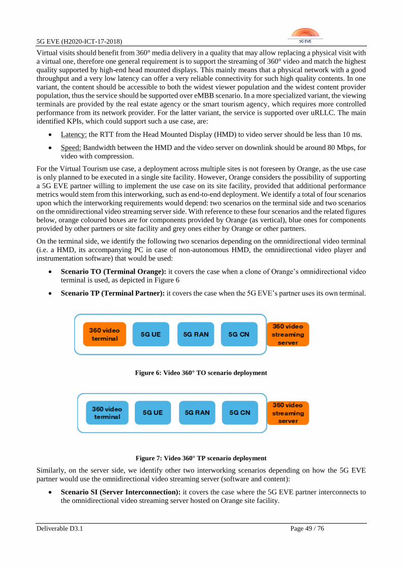
5G EVE (H2020-ICT-17-2018)
Deliverable D3.1 Page 49 / 76
Virtual visits should benefit from 360° media delivery in a quality that may allow replacing a physical visit with
a virtual one, therefore one general requirement is to support the streaming of 360° video and match the highest
quality supported by high-end head mounted displays. This mainly means that a physical network with a good
throughput and a very low latency can offer a very reliable connectivity for such high quality contents. In one
variant, the content should be accessible to both the widest viewer population and the widest content provider
population, thus the service should be supported over eMBB scenario. In a more specialized variant, the viewing
terminals are provided by the real estate agency or the smart tourism agency, which requires more controlled
performance from its network provider. For the latter variant, the service is supported over uRLLC. The main
identified KPIs, which could support such a use case, are:
• Latency: the RTT from the Head Mounted Display (HMD) to video server should be less than 10 ms.
• Speed: Bandwidth between the HMD and the video server on downlink should be around 80 Mbps, for
video with compression.
For the Virtual Tourism use case, a deployment across multiple sites is not foreseen by Orange, as the use case
is only planned to be executed in a single site facility. However, Orange considers the possibility of supporting
a 5G EVE partner willing to implement the use case on its site facility, provided that additional performance
metrics would stem from this interworking, such as end-to-end deployment. We identify a total of four scenarios
upon which the interworking requirements would depend: two scenarios on the terminal side and two scenarios
on the omnidirectional video streaming server side. With reference to these four scenarios and the related figures
below, orange coloured boxes are for components provided by Orange (as vertical), blue ones for components
provided by other partners or site facility and grey ones either by Orange or other partners.
On the terminal side, we identify the following two scenarios depending on the omnidirectional video terminal
(i.e. a HMD, its accompanying PC in case of non-autonomous HMD, the omnidirectional video player and
instrumentation software) that would be used:
• Scenario TO (Terminal Orange): it covers the case when a clone of Orange’s omnidirectional video
terminal is used, as depicted in Figure 6
• Scenario TP (Terminal Partner): it covers the case when the 5G EVE’s partner uses its own terminal.
Figure 6: Video 360° TO scenario deployment
Figure 7: Video 360° TP scenario deployment
Similarly, on the server side, we identify other two interworking scenarios depending on how the 5G EVE
partner would use the omnidirectional video streaming server (software and content):
• Scenario SI (Server Interconnection): it covers the case where the 5G EVE partner interconnects to
the omnidirectional video streaming server hosted on Orange site facility.

5G EVE (H2020-ICT-17-2018)
Deliverable D3.1 Page 50 / 76
• Scenario SO (Server On-board): it covers the case where the 5G EVE partner on-board Orange’s
omnidirectional video streaming server into its virtualization infrastructure and (optionally) into its
management and orchestration infrastructure. This scenario is still to be clearly defined in terms of
(performance) requirements (at control and data planes) for cross-site deployment, and its validation is
considered in this first phase of the project at lower priority with respect to the single site deployment,
The implementation of this scenario will be deeply discussed with other partners during the second
phase of the project, i.e. year 2020.
Figure 8: Video 360° SI scenario deployment
Figure 9: Video 360° SO scenario deployment
In addition to the above four potential interworking scenarios, the Virtual Visit use case experiments execution
poses a set of technical requirements to be addressed by the 5G EVE platform, which are summarized in the
tables below.
Table 37: Virtual visit over 5G Use Case scenario: deployment technical requirements
Deployment
requirements Priority Description
Slices provisioning High
The use case requires the instantiation of eMBB slices to support
the 360° video distribution and the instantiation of uRLLC
slices, with upper goal to support interactive communications
between HMD and video server.
Slice network domains High
The required slices span in general across RAN, XHAUL, and
Core segments. Edge resources may be needed for video
caching.
Dynamic and on-
demand instantiation
and termination of
service
High The eMBB and uRLLC slices should be dynamically
instantiated and terminated on-demand.
5G EVE (H2020-ICT-17-2018)
Deliverable D3.1 Page 51 / 76
Table 38: Virtual visit over 5G Use Case scenario: monitoring/analysis technical requirements
Monitoring/Analysis
requirements Priority Description
5G network
performance
monitoring
High
The system should be able to provide 5G network performance
measurements, including:
• Delivered bandwidth for video streaming in downlink:
validation of KPI from 40 up to 80 Mbps per mobile
user.
• Maximum latency from HMD to video server less than
10 ms.
Monitoring of the QoE
in the reception of the
360°video
High The system should be able to estimate the QoE perceived for the
reception of the transmitted 360° video.

5G EVE (H2020-ICT-17-2018)
Deliverable D3.1 Page 52 / 76
4 Target interworking capabilities, features and services
This section defines a first proposal of the interworking capabilities, features and services that shall be provided
by the 5G EVE platform. We consider, in the scope of the preliminary interworking framework architecture
definition, all the features and services required to provide a common interface and model on top of the 5G EVE
site facilities. For this scope, a list of target capabilities each 5G EVE site should expose to enable this
interworking common model is also defined. In addition, cross-site connectivity aspects and requirements are
also considered to enable interworking in executing vertical experiments involving several sites.
4.1 Preliminary interworking framework architecture
Starting from the vertical oriented technical requirements derived from the 5G EVE use cases and reported in
section 3, and also considering the heterogeneous services and features offered by each site facility described
in section 2, a preliminary interworking framework architecture scheme is proposed. This proposal aims at
identifying a minimum set of interworking capabilities functions to be supported by the 5G EVE end-to-end
facility.
The 5G EVE interworking framework is a unique selling point of the 5G EVE end-to-end facility, which aims
at providing a unified and integrated experimentation platform spanning heterogeneous sites, where diverse 5G
capabilities and tools are deployed. Therefore, it is a combination of coordination features for the seamless
orchestration and execution of vertical use case experiments over heterogeneous infrastructures.
Therefore, its design and implementation are basically performed from scratch, trying to enhance, combine and
integrate, where possible, existing solutions for multi-site orchestration, catalogue and inventory of NFV
network services, VNFs and network slices, monitoring of network and service performances. Figure 10 shows
the preliminary interworking framework architecture diagram and high-level functional split, as well as its
logical positioning with respect to the 5G EVE experiment portal and the four site facilities. In particular, the
interworking framework sits between the experiment portal, that is the frontend of the 5G EVE platform and
the site facilities where the vertical use case experiments have to be deployed for testing and validation 5G and
service specific KPIs.
Figure 10: Preliminary interworking framework architecture
The two main reference points exposed and provided by the 5G EVE interworking framework are:
• The Interworking API exposed at the northbound towards the 5G EVE experiment portal;

5G EVE (H2020-ICT-17-2018)
Deliverable D3.1 Page 53 / 76
• The adaptation and abstraction interface at the southbound for providing a common and unified access
to the individual site facilities services and APIs.
As a general reference for modelling and descriptions of end-to-end network services and slices within the
interworking framework, the followed approach is the one proposed by ETSI NFV in the Evolution and
Ecosystem WG work item EVE012 [37]. In the context of the interworking framework, the most relevant
considerations provided by ETSI NFV EVE012 are those related to information models and architectural
aspects, specifically targeting 3GPP network slice concepts, described in 3GPP 28.801 [38] and specified in
3GPP 28.530 [39]. Indeed, 3GPP defines a network slice as a combination of zero or more network slice subnets,
following a kind of recursive approach, where each subnet can contain zero or more other subnets, as well as
zero or more network functions. Network functions in 3GPP are associated to VNFs and PNFs, therefore a
direct mapping of an NFV Network Service as a resource-centric view of a network slice is highly appropriate.
Moreover, as 3GPP foresees that network slice subnet instances can be shared by multiple network slice
instances, and virtualized resources for a slice subnet (including compute, network and storage) can be mapped
to nested NFV Network Service concept. In this way, as shown in Figure 11, a correspondence between network
slice instances and network slice subnets instances with NFV Network Services exists, following the
relationship provided by the dotted arrows.
Figure 11: 3GPP and NFV information models potential mapping (source [37])
In this context, the Interworking API can be considered as a collection of primitives that aims at exposing a
common interface and model for end-to-end Network Services and slices provisioning in support of the vertical
use case experiments. It is important to highlight that the interworking API is not only a provisioning interface.
Indeed, it is conceived to expose additional features for the operation of the vertical use case experiments,
including runtime configuration of the network services and slice elements (e.g. VNFs), and monitoring of
network and service performance metrics in support of the validation of targeted KPIs within each experiment.
In summary, the interworking API exposes at least the following services:
• Access to multi-site catalogue to allow the 5G EVE experiment portal to:
o Retrieve Network Service and VNF Descriptors modelling the network slices that can be
provisioned in the end-to-end facility;

5G EVE (H2020-ICT-17-2018)
Deliverable D3.1 Page 54 / 76
o On-board new Network Service and VNF Descriptors to fulfil the requirements of vertical use
case experiments.
• Access to multi-site inventory information to allow the 5G EVE experiment portal to retrieve details of
already provisioned Network Services in support of vertical use case experiments;
• Provisioning and lifecycle management of end-to-end Network Services in line with ETSI NFV
Management and Orchestration (MANO) principles and operations.;
• Configuration of 5G network and service performance metrics to be monitored and collected during the
execution of vertical use case experiments;
• Common and site independent access to collected monitoring information for each vertical use case
experiment, for processing and analysis by the 5G EVE experiment testing and validation tools;
• Runtime configuration of Network Services and VNFs, to enable the 5G EVE validation framework to
dynamically apply vertical-oriented service logics and configurations (following the vertical’s
experiment requirements and constraints) with a common approach and interface. It is worth to highlight
that this runtime configuration is not intended, at least in this initial phase of the interworking
framework definition, to be directly exposed and offered to the verticals
On the other hand, the Adaptation Layer, shown in Figure 10, has the main goal to abstract the heterogeneous
capabilities and APIs exposed by the 5G EVE site facilities, mostly focusing, in this preliminary interworking
framework definition, on orchestration and control features. Therefore, it exposes to the interworking
framework components a set of common internal APIs and models for accessing per-site management, control,
orchestration and monitoring services, and translates them into the site-specific APIs and models. In particular,
the common APIs and models provided by the adaptation layer are intended to provide transparent access to
those site features and services listed in section 4.3 as required to fulfil the vertical oriented technical
requirements. As depicted in Figure 10, for each of these required per-site features and services, the adaptation
layer is equipped with specific drivers providing the required translation from the common interface to the site-
specific APIs.
4.1.1 Overview of the interworking framework components
The preliminary interworking framework architecture, presented in Figure 10, is decomposed into the following
functional components: Multi-site Network Service Orchestrator, Multi-site Catalogue, Multi-site Inventory,
Runtime Configurator, and Data Collection Manager.
The preliminary interworking framework architecture, presented in Figure 10, is decomposed into the following
functional components: Multi-site Network Service Orchestrator, Multi-site Catalogue, Multi-site Inventory,
Runtime Configurator, and Data Collection Manager.
The Multi-site Network Service Orchestrator is the core component within the interworking framework and
responsible for coordinating the provisioning and lifecycle of Network Services across the site facilities, as
required to deploy end-to-end network slices for the execution of vertical use case experiments. It leverages on
the per-site orchestration components and features, as they provide the fundamental logics and coordination
within each 5G EVE site facility. Following the ETSI NFV EVE012 [37] approach described above, the Multi-
site Network Service Orchestrator allows to provision end-to-end network slices as a combination of NFV
Network Services, possibly across different sites when required. For this, the Multi-site Network Service
Orchestrator contributes to the interworking API with lifecycle management operations, including on-boarding,
based on the ETSI NFV SOL005 APIs [35], which specify the NFV Orchestrator northbound interface.
Therefore, it is supposed to operate on top and coordinate, through the Adaptation Layer, the different per-site
orchestration and control tools, e.g. at RAN, MEC or edge, transport SDN, NFV segment level. The Multi-site
Network Service Orchestrator also provides the logic for selecting where to deploy Network Services and VNFs,
according to the specific performance, resource and location constraints received through the interworking API
and expressed by the vertical for the execution of its experiment. For this specific selection purpose, the Multi-
site Network Service Orchestrator leverages on the information (in terms of running instances and their
performances) available from the Multi-site Inventory and the Data Collection Manager. The Multi-site

5G EVE (H2020-ICT-17-2018)
Deliverable D3.1 Page 55 / 76
Network Service Orchestrator owns and manages the Multi-site Catalogue and the Multi-site Inventory, and it
is responsible for keeping the information stored consistent and up to date.
The Multi-site Catalogue decouples the Network Service Descriptors exposed to the 5G EVE experiment
portal, which may span multiple sites and logically represent the actual network slice offers from the Network
Service Descriptors collected from each of the site facilities, representing the actual capabilities of the sites. By
maintaining both these levels, the Multi-site catalogue can keep track of dependencies and restrictions of each
5G EVE site facilities, as required for deciding where to deploy a given network slice in support of a specific
vertical use case experiment. For the time being, in this preliminary interworking architecture definition,
verticals will be able to on-board their own VNFs in the Multi-site catalogue, as an automated procedure from
the 5G EVE experimental portal. However, the option of having vertical VNFs on-boarding as an offline process
in the per-site catalogues is also left open, especially for this first phase of the project. In addition to the legacy
NFV-related information, the Multi-site Catalogue is intended to store any per-site additional information
required for the vertical use case experiment and that is not dynamically exposed by the sites as described in
section 4.3.
The Multi-site Inventory is the counterpart of the catalogue component for what concerns the information on
provisioned and instantiated network slices in the 5G EVE end-to-end facility. It is fully managed, in terms of
information stored, by the Multi-site Network Service Orchestrator, and it maintains detailed information of
running. The Multi-site inventory exposes to the 5G EVE experiment portal the end-to-end Network Services
instances deployed for a given experiment, augmented with additional service level information (e.g. list of
monitored network and service performance metrics, runtime configurations, etc.). At the same time, it keeps
the relation with the actual provisioned per-site Network Services, VNF instances and resource configurations
(e.g. at RAN, MEC segments) in support of the given vertical use case experiment. The Multi-site Inventory
also allows to collect (through the Adaptation Layer or provisioned offline) and store any Network Service and
network slice that may be pre-provisioned in each site, and that could be selected by the Multi-site Network
Service Orchestrator for deploying and running vertical use case experiments.
The Data Collection Manager is a key component within the interworking framework and it coordinates the
collection and persistence of all those network and vertical tailored service performance metrics that are required
to be monitored during the execution of experiments for testing and validation of the targeted KPIs. On the one
hand, through the interworking API, for each experiment, it is allowed to configure the performance metrics
that have to be measured for validating the specific use case KPIs. On the other hand, in turn, this monitoring
configuration is mapped, through the proper logic provided by the Adaptation Layer, into a request for selective
collection of network and service-related metrics to the involved 5G EVE sites. In this way, only the metrics
needed to validate the KPIs required by the vertical will be monitored in each of the involved site facilities and
collected by the Data Collection Manager (either with explicit queries or through publish/subscribe
mechanisms) for their storage in a common database shared with the 5G EVE experiment portal.
The Runtime Configurator allows to apply tailored runtime configurations to the provisioned end-to-end
Network Services and VNFs in support of the vertical use case experiments. While the Multi-site Network
Service Orchestrator can handle Day0 and Day1 configurations during the Network Services and VNFs
instantiation phases (i.e. by enforcing them through the per-site exposed NFV Orchestration VNF configuration
services), experiment specific and vertical oriented Day2 configurations can be applied through the interworking
API via a common interface exposed towards the 5G EVE experiment portal. This requires that each site facility,
in turn, exposes such capability for Day2 VNF configuration.
4.2 Interworking framework evolution roadmap
We propose a stepwise approach to the final interworking target, based on the complexity and the vertical
requirements.

5G EVE (H2020-ICT-17-2018)
Deliverable D3.1 Page 56 / 76
Figure 12: Interworking framework roadmap
In the roadmap, depicted in Figure 12, there are two main dimensions:
Single site. Although the main purpose of the Interworking framework is to allow use cases in several 5G EVE
sites, it is also important to verify that a Vertical use case can be deployed in any site. Thus, the first versions
of the framework will allow to deploy a Network Service in one site. We differentiate two phases:
• Deploy an NSD (Network Service Descriptor) using pre-provisioned, pre-certified VNFs: Verticals are
allowed to define network services that use existing VNFs. Any application required for the Vertical
experiment shall be provisioned and certified in each site.
• Deploy full NSD, including VNFs. It is not still clear if this requirement can be fulfilled completely,
due to the current state-of-art of cloud technologies and their diversity.
Interworking. The other characteristic included in the roadmap is the capability of interconnecting more than
one 5G EVE site. Here, we distinguish among the kinds of cross-site traffic:
• Orchestration should be a basic requirement for all sites;
• Control traffic (both network and application);
• Management traffic, e.g. for monitoring data;
• Data plane traffic.
Data plane traffic is the most demanding one and is more difficult because it depends on physical network in
order to be compliant with the requirements (e.g. GEANT network between 5TONIC and France). However, so
far, we do not have a clear vertical use case for using it, so we decided to defer the analysis of this
interconnection, until we receive the new ICT-19 vertical projects.
Table 39: Requirements per 5G Service Type
Single site with pre-
provisioned Apps
Single site with vertical
Apps provisioning
interface
Interworking of
orchestration
and/or control
Interworking
of data plane
eMBB X X X X
mMTC X X
URLLC X X
In Table 39, we show the required phase of the interworking framework per 5G service type. We assume that
uRLLC services are not going to use inter-site deployments, as their requirement of bandwidth and latency
discard any deployment that physically is not near the RAN. Also, we expect that only eMBB use cases will
Single site with pre-provisioned
Apps
Interworking of nworchestration, nw
control or App.Control traffic
Single site with vertical App provisioning
interface
Interworking of data plane traffic
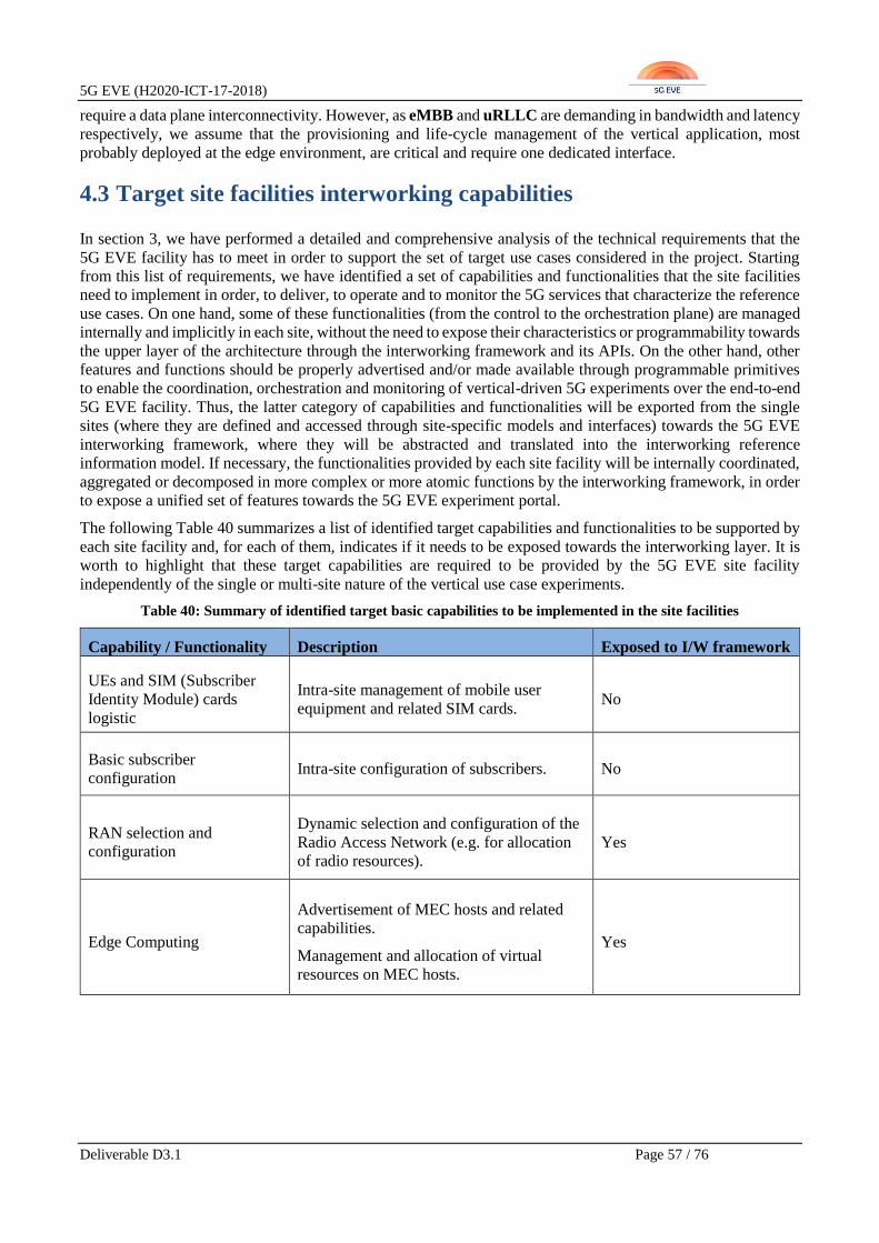
5G EVE (H2020-ICT-17-2018)
Deliverable D3.1 Page 57 / 76
require a data plane interconnectivity. However, as eMBB and uRLLC are demanding in bandwidth and latency
respectively, we assume that the provisioning and life-cycle management of the vertical application, most
probably deployed at the edge environment, are critical and require one dedicated interface.
4.3 Target site facilities interworking capabilities
In section 3, we have performed a detailed and comprehensive analysis of the technical requirements that the
5G EVE facility has to meet in order to support the set of target use cases considered in the project. Starting
from this list of requirements, we have identified a set of capabilities and functionalities that the site facilities
need to implement in order, to deliver, to operate and to monitor the 5G services that characterize the reference
use cases. On one hand, some of these functionalities (from the control to the orchestration plane) are managed
internally and implicitly in each site, without the need to expose their characteristics or programmability towards
the upper layer of the architecture through the interworking framework and its APIs. On the other hand, other
features and functions should be properly advertised and/or made available through programmable primitives
to enable the coordination, orchestration and monitoring of vertical-driven 5G experiments over the end-to-end
5G EVE facility. Thus, the latter category of capabilities and functionalities will be exported from the single
sites (where they are defined and accessed through site-specific models and interfaces) towards the 5G EVE
interworking framework, where they will be abstracted and translated into the interworking reference
information model. If necessary, the functionalities provided by each site facility will be internally coordinated,
aggregated or decomposed in more complex or more atomic functions by the interworking framework, in order
to expose a unified set of features towards the 5G EVE experiment portal.
The following Table 40 summarizes a list of identified target capabilities and functionalities to be supported by
each site facility and, for each of them, indicates if it needs to be exposed towards the interworking layer. It is
worth to highlight that these target capabilities are required to be provided by the 5G EVE site facility
independently of the single or multi-site nature of the vertical use case experiments.
Table 40: Summary of identified target basic capabilities to be implemented in the site facilities
Capability / Functionality Description Exposed to I/W framework
UEs and SIM (Subscriber
Identity Module) cards
logistic
Intra-site management of mobile user
equipment and related SIM cards. No
Basic subscriber
configuration Intra-site configuration of subscribers. No
RAN selection and
configuration
Dynamic selection and configuration of the
Radio Access Network (e.g. for allocation
of radio resources).
Yes
Edge Computing
Advertisement of MEC hosts and related
capabilities.
Management and allocation of virtual
resources on MEC hosts.
Yes
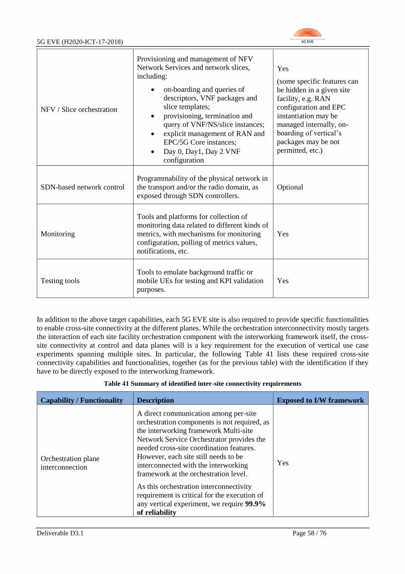
5G EVE (H2020-ICT-17-2018)
Deliverable D3.1 Page 58 / 76
NFV / Slice orchestration
Provisioning and management of NFV
Network Services and network slices,
including:
• on-boarding and queries of
descriptors, VNF packages and
slice templates;
• provisioning, termination and
query of VNF/NS/slice instances;
• explicit management of RAN and
EPC/5G Core instances;
• Day 0, Day1, Day 2 VNF
configuration
Yes
(some specific features can
be hidden in a given site
facility, e.g. RAN
configuration and EPC
instantiation may be
managed internally, on-
boarding of vertical’s
packages may be not
permitted, etc.)
SDN-based network control
Programmability of the physical network in
the transport and/or the radio domain, as
exposed through SDN controllers.
Optional
Monitoring
Tools and platforms for collection of
monitoring data related to different kinds of
metrics, with mechanisms for monitoring
configuration, polling of metrics values,
notifications, etc.
Yes
Testing tools
Tools to emulate background traffic or
mobile UEs for testing and KPI validation
purposes.
Yes
In addition to the above target capabilities, each 5G EVE site is also required to provide specific functionalities
to enable cross-site connectivity at the different planes. While the orchestration interconnectivity mostly targets
the interaction of each site facility orchestration component with the interworking framework itself, the cross-
site connectivity at control and data planes will is a key requirement for the execution of vertical use case
experiments spanning multiple sites. In particular, the following Table 41 lists these required cross-site
connectivity capabilities and functionalities, together (as for the previous table) with the identification if they
have to be directly exposed to the interworking framework.
Table 41 Summary of identified inter-site connectivity requirements
Capability / Functionality Description Exposed to I/W framework
Orchestration plane
interconnection
A direct communication among per-site
orchestration components is not required, as
the interworking framework Multi-site
Network Service Orchestrator provides the
needed cross-site coordination features.
However, each site still needs to be
interconnected with the interworking
framework at the orchestration level.
As this orchestration interconnectivity
requirement is critical for the execution of
any vertical experiment, we require 99.9%
of reliability
Yes

5G EVE (H2020-ICT-17-2018)
Deliverable D3.1 Page 59 / 76
Control plane
interconnection
Cross-site connectivity for control plane
communications (e.g. among 4G or 5G core
control plane components) may be required
for the execution of cross-site use cases.
The requirement is to have cross-site
connection with:
• 99.9% of reliability
• minimum of 20Mbps of
bandwidth
Optional. It may require
coordination from the
interworking framework
Data plane interconnection
Data plane cross-site connection is not
required from the current 5G EVE vertical
use case, but it could be needed by one of
the future use cases, e.g. from ICT-19
projects.
As a recommendation and future
requirement, this cross-site connection
should have:
• 99.9% of reliability,
• 200 Mbps of bandwidth
• variable latency requirement,
depending on the distance between
sites (as detailed in Section 5)
No. This is an inter-site
requirement and it is not
required at this initial phase
of the project
More details about the target capabilities and features to be provided by each 5G EVE site facility (as listed in
Table 40 and Table 41 above) and that enable the interworking framework model and approach described in
section 4.1, are provided in the following subsections.
4.3.1 UE and SIM cards logistic
The execution of the 5G EVE vertical use case experiments requires the availability of 5G ready UE and SIM
cards. It is assumed that their procurement, identification and maintenance will be completely under the
responsibility and management of each site and involved verticals. Each site/vertical is free to implement its
own procedures and mechanisms for handling UEs and SIM cards.
The availability of UEs and SIM cards, together with their characteristics, will be anyway manually fed and
stored in the interworking framework Multi-site Catalogue and exposed to the 5G EVE experiment portal. Thus,
they will enable verticals to select and associate them to their use case experiments.
4.3.2 Basic Subscriber configuration
It is not expected that 5G EVE sites will expose the interfaces for configuring the subscribers. 5G EVE sites
shall provide a set of subscribers for the experiments, possibly covering the different services provided by the
site (eMBB, mMTC, uRLLC). Information about the available subscriber configuration sets will be stored in
the interworking framework Multi-site Catalogue.
4.3.3 Radio Access Network selection and configuration
Each 5G EVE site is requested to advertise its RAN capabilities, at least in terms of geographical coverage.
Therefore, whenever multiple RAN technologies and coverage options are available, the 5G EVE sites shall
expose them to the interworking framework. This is required at the Multi-site Network Service Orchestrator to
take appropriate decisions on where to deploy a given vertical use case experiment, either within a single site

5G EVE (H2020-ICT-17-2018)
Deliverable D3.1 Page 60 / 76
or across multiple sites. These RAN capabilities and coverage information are thus stored in the Multi-site
Catalogue for their usage within the interworking framework.
As an additional consequent RAN-related capability, each 5G EVE site shall give the possibility to select either
the geographical area or RAN technology (or both) when provisioning a Network Service or a network slice in
a 5G EVE site in support. The exposure of dedicated interfaces for dynamic provisioning and configuration of
RAN resources are considered for the time being (i.e. in the context of the preliminary interworking framework
definition) as optional, as they are not required in all the use cases. In any case, RAN resources provisioning
and configuration can be managed by each site NFV or slice orchestrator and thus being transparent for the
interworking framework.
4.3.4 Edge Computing
The availability of edge computing environments is crucial for the execution of most of the 5G EVE vertical
use cases. Multiple technology solutions are allowed, including MEC, fog computing and distributed edge
cloud. Each 5G EVE site is required to advertise and expose to the interworking framework its availability of
edge computing resources and capabilities (hosts, geographical location, network connectivity constraints and
characteristics).
Additionally, the 5G EVE sites shall also manage the provisioning and configuration of virtual resources on
MEC or edge hosts, according to network and service performance requirements (e.g. latency) and location
constraints. This implies the implementation of advanced functionalities for network traffic steering and
breakout at MEC/edge hosts and access to location services. However, the exposure of these features and
services towards the interworking framework is subject to the specific per-site orchestration approach and
paradigm. Indeed, the MEC/edge control and orchestration may be hidden under NFV or slice orchestration
services.
4.3.5 NFV / Slice orchestration
Given the network slice modelling and approach followed by the interworking framework and based on the
ETSI NFV EVE012 [37]principles (see section 4.1), the support of NFV orchestration services in each 5G EVE
site has to be considered as one of the key mandatory features. However, NFV orchestration includes a wide
plethora of capabilities, features and functionalities for the provisioning and lifecycle management of network
slices, Network Services and VNFs (instantiation, modification, scaling, termination, etc.). In the context of 5G
EVE, the per-site NFV orchestration tools have to take into account the interaction with the interworking
framework and its Multi-site Network Service Orchestrator, that acts as an overarching coordinator of NFV
orchestrators across sites, and if needed within the same site. Indeed, it is assumed that each 5G EVE site shall
expose NFV orchestration capabilities, but it is allowed for each site facility to have more than one NFV
orchestrator, e.g. to manage different portions of the infrastructure possibly dedicated to deploying different
types of service (vertical applications and VNFs vs. 5G mobile network VNFs).
For the sake of their integration with the interworking framework and thus the 5G EVE platform, the site NFV
orchestrators shall offer:
• Access to NFV catalogues for querying and on-boarding VNFs and Network Service Descriptors;
• Network Service and VNF lifecycle management, including provisioning, query and termination of
instances;
• Network Service and VNF dynamic modification, e.g. through scaling operations;
• Day0, Day1 and Day2 configuration of VNFs.
As optional features, NFV orchestration could provide advanced capabilities for Network Service self-healing
and auto-scaling in support of demanding use cases with very stringent requirements in terms of availability and
service continuity. Moreover, as further optional and advanced capability, the NFV orchestrator could directly
manage and expose RAN and EPC/5G Core instances.

5G EVE (H2020-ICT-17-2018)
Deliverable D3.1 Page 61 / 76
4.3.6 SDN-based network control
Each 5G EVE site facility may make use of SDN-based network control solutions to dynamically program the
physical network in the transport or the radio domains, e.g. leveraging on one or more SDN controllers. From a
5G EVE interworking framework perspective, the exposure of SDN network control primitives provisioning of
network connectivity in the intra-site 5G infrastructure is not considered as mandatory feature. Such
programmable network control capabilities can be considered as hidden under the management of per-site NFV
and slice orchestrators.
However, in the case of 5G EVE sites with multiple NFV orchestrators deployed and exposed to the
interworking framework, the exposure of SDN-based network control primitives may ease the interconnection
and stitching of independent Network Services towards the provisioning of end-to-end intra-site network slices.
4.3.7 Monitoring
The monitoring of 5G network and service performance metrics is a key requirement in 5G EVE to enable
testing and validation of the vertical use case targeted KPIs. Indeed, 5G EVE provides an end-to-end
experimentation facility, where verticals can deploy their use cases and validate 5G technologies against their
application domains to demonstrate the benefits they can achieve. For this reason, each 5G EVE site shall
provide advanced monitoring capabilities to measure a wide and complete set of 5G network and service metrics
that allow fulfilling the vertical use case requirements, as reported in section 3.
More than that, the dynamic and per-experiment configuration of 5G network and service metrics to be
measured and collected is required to be exposed towards the 5G EVE interworking framework by each site
facility. This allows the Data Collection Manager in the interworking framework to translate and map the
vertical use case experiment target KPIs into lower level metrics to be measured and collected. At the time of
writing, given the preliminary nature of the interworking framework definition, 5G EVE sites have two options
for exposing monitored data to the Data Collection Manager in the interworking framework:
• Offer an interface for polling 5G network and service performance metrics;
• Push the 5G network and service performance metrics into the common database.
4.3.8 Testing tools
The execution of the 5G EVE vertical use case experiments requires realistic conditions for proper testing and
validation of the targeted KPIs. Indeed, to enable 5G EVE (and external users when they will start to use the
platform) verticals to validate the 5G technology’s expected benefits in terms of network and service
performances, the experiments over the project end-to-end facility need to be performed in the appropriate real-
time conditions.
This means that at least background traffic generators and emulators of UEs shall be available for their usage in
the experiments. Therefore, as a minimum requirement, testing tools need to be known (together with their
capabilities) at the interworking framework and stored into the Multi-site Catalogue for their selection and usage
in vertical use case experiments. More than the availability, it will be required that each site should expose
dedicated interfaces to configure this testing as part of automated experiment execution.
Whether these configuration interfaces will be exposed to the interworking framework or directly to the testing
and validation framework within the 5G EVE experiment portal is still under discussion (in WP5 and WP3).
4.3.9 Cross-site connectivity
5G EVE sites shall declare the type of connection available towards Internet or other public networks. Also,
they must provide the capability of creating an interconnection with other 5G EVE sites using IP VPNs (in
compliance with the plans of each site facility reported in D2.1 [2]), and where possible and available leveraging
on the pan-European GEANT research network.
Cross-site orchestration connectivity is required for enabling the communication between the interworking
framework and each of the 5G EVE sites. This communication is basic for the execution of any vertical

5G EVE (H2020-ICT-17-2018)
Deliverable D3.1 Page 62 / 76
experiment and for that reason we included a basic requirement for this type of cross-site connectivity, which
expects a reliability of at least 99.9%.
Cross-site control plane connectivity is required for allowing cross-site execution of a vertical use case
experiments, when control plane interworking is required for proper communication among control VNFs or
network functions in general. As example, for the Industry 4.0 use case scenario (as reported in section 3.1.3),
advanced deployments may require multi-site execution with interconnection at the level of the LTE S6a
interface for managing subscriber data in standard roaming. Similarly, considering the Smart Tourism scenario
of section 3.1.2, a cross-site control plane interworking at LTE S1-11 interfaces level may be required to radio
and edge elements and functions deployed at vertical site (e.g. IFEMA) and core in the 5G EVE 5TONIC site.
Taking these two cases as references for expressing some target performances in the case of control plane
interworking, we require a cross-site connectivity that guarantees a minimum bandwidth of 20 Mbps, with a
reliability of 99.9%.
Cross-site data plane connectivity is not to be considered as a strict requirement at this stage of the project, as
none of the 5G EVE vertical use cases need it for its execution. In any case, it is expected that future use case
experiments, coming from new verticals using the 5G EVE platform (e.g. from ICT-19 projects) will bring new
requirements, including interworking at the data plane level for multi-site deployments. For this, we included a
preliminary recommendation for cross-site connection with the following characteristics: 99.9% of reliability,
200 Mbps of guarantee bandwidth and maximum latency that depends on the distance of each site (as listed in
the form of interworking recommendations in section 5).
5G EVE (H2020-ICT-17-2018)
Deliverable D3.1 Page 63 / 76
5 Site facilities’ technical gaps and interworking recommendations
This section aims at providing for each 5G EVE site facility a preliminary list of technical gaps and interworking
recommendations against the identified target capabilities and functionalities (as reported in section 4) that the
site facilities need to implement to deliver the 5G services in support of the reference 5G EVE vertical use cases.
As a preparatory step towards the identification of per-site technical gaps and interworking recommendations,
we have matched the target capabilities and features, listed in section 4.3, against the vertical use cases
requirements reported in section 3, and produced as a result matrix in Error! Reference source not found.
below. In particular, for each vertical use case scenario (i.e. columns in Error! Reference source not found.),
we have mapped its requirements to the target capabilities and features (i.e. rows in Error! Reference source
not found.) required to fulfil them. The vertical use cases scenarios are labelled in Error! Reference source
not found. as following:
• UC#1 - Smart Transport: Intelligent railway for smart mobility
• UC#2 - Smart Tourism: Augmented Fair experience
• UC#3 - Industry 4.0: Autonomous vehicles in manufacturing environments
• UC#4 - Smart Energy: Fault management for distributed electricity generation in smart grids
• UC#5 - Smart Cities: Safety and Environment – Smart Turin
• UC#6 - Smart Cities: Safety and Environment – Connected Ambulance
• UC#7 - Smart Cities: Safety and Environment – Health Monitoring and Forecasting, Smart Mobility
and Smart Home
• UC#8 - Media & Entertainment: UHF Media, On-Site Live Event Experience and Immersive and
Integrated Media
• UC#9 - Media & Entertainment: Virtual Visit over 5G
Starting from Error! Reference source not found. and considering that, for the time being, each of the 5G
EVE vertical use case scenario will be executed in a single site facility, the following sub-sections identify a
preliminary list of technical gaps and interworking recommendations for each site facility, as a match of Error!
Reference source not found. against the site facilities service capabilities reported in section 2. However, this
initial list has to be considered valid and applicable for any vertical use case experiment (i.e. either it will be
deployed in single or multi sites), thus including any potential future scenario coming from new ICT-19 projects’
verticals. As a complement, specific additional recommendations are included for each site in support of the
cross-site connectivity features defined in 4.3.9.
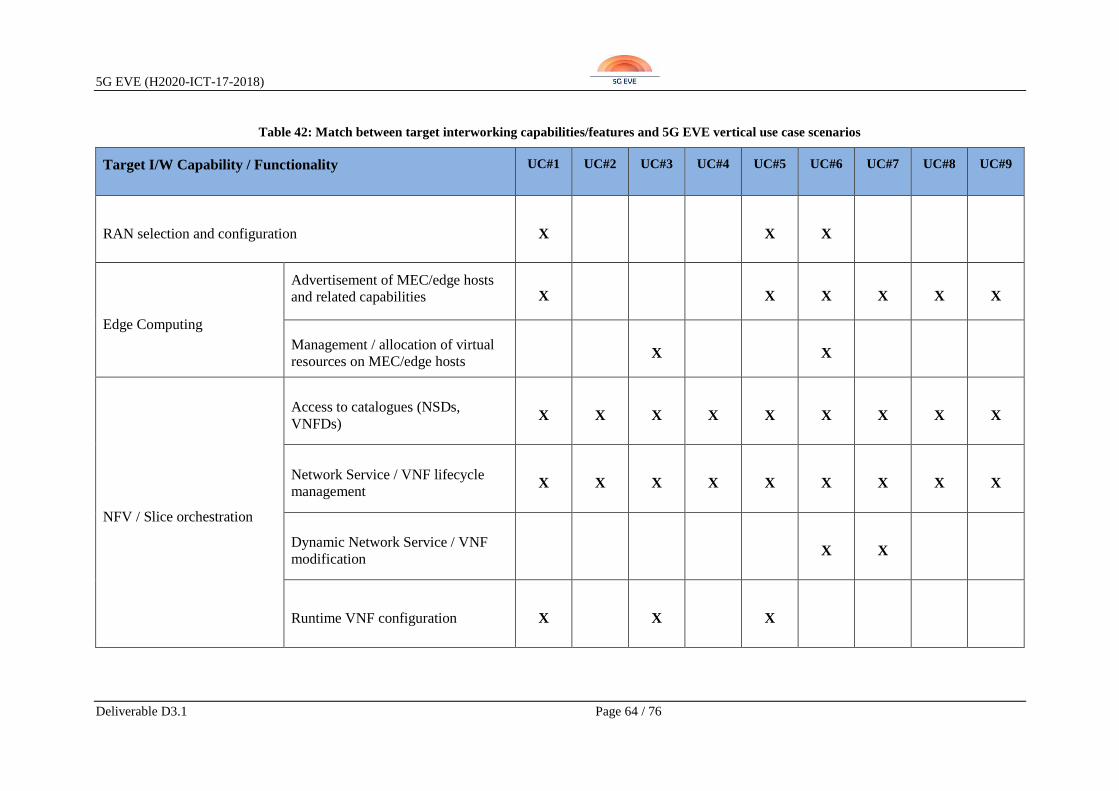
5G EVE (H2020-ICT-17-2018)
Deliverable D3.1 Page 64 / 76
Table 42: Match between target interworking capabilities/features and 5G EVE vertical use case scenarios
Target I/W Capability / Functionality UC#1 UC#2 UC#3 UC#4 UC#5 UC#6 UC#7 UC#8 UC#9
RAN selection and configuration X X X
Edge Computing
Advertisement of MEC/edge hosts
and related capabilities X X X X X X
Management / allocation of virtual
resources on MEC/edge hosts X X
NFV / Slice orchestration
Access to catalogues (NSDs,
VNFDs) X X X X X X X X X
Network Service / VNF lifecycle
management X X X X X X X X X
Dynamic Network Service / VNF
modification X X
Runtime VNF configuration X X X

5G EVE (H2020-ICT-17-2018)
Deliverable D3.1 Page 65 / 76
SDN-based network control X
Monitoring
5G network performance metrics X X X X X X
5G service performance metrics X X X X X
QoE estimation X X X X X
Testing tools X X X
Cross-site connectivity
Orchestration plane interconnection X X X X X X X X X
Control plane interconnection X X
Data plane interconnection X X
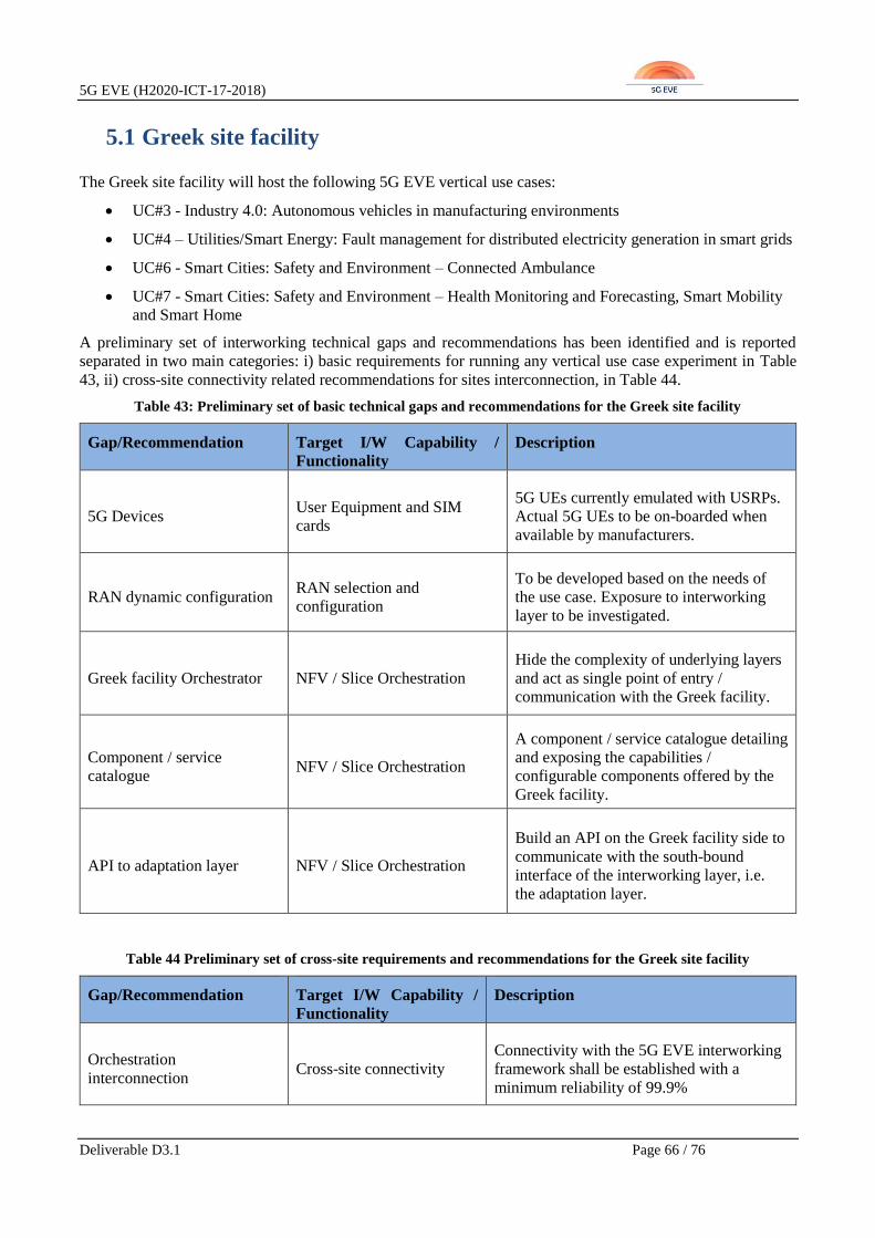
5G EVE (H2020-ICT-17-2018)
Deliverable D3.1 Page 66 / 76
5.1 Greek site facility
The Greek site facility will host the following 5G EVE vertical use cases:
• UC#3 - Industry 4.0: Autonomous vehicles in manufacturing environments
• UC#4 – Utilities/Smart Energy: Fault management for distributed electricity generation in smart grids
• UC#6 - Smart Cities: Safety and Environment – Connected Ambulance
• UC#7 - Smart Cities: Safety and Environment – Health Monitoring and Forecasting, Smart Mobility
and Smart Home
A preliminary set of interworking technical gaps and recommendations has been identified and is reported
separated in two main categories: i) basic requirements for running any vertical use case experiment in Table
43, ii) cross-site connectivity related recommendations for sites interconnection, in Table 44.
Table 43: Preliminary set of basic technical gaps and recommendations for the Greek site facility
Gap/Recommendation Target I/W Capability /
Functionality
Description
5G Devices User Equipment and SIM
cards
5G UEs currently emulated with USRPs.
Actual 5G UEs to be on-boarded when
available by manufacturers.
RAN dynamic configuration RAN selection and
configuration
To be developed based on the needs of
the use case. Exposure to interworking
layer to be investigated.
Greek facility Orchestrator NFV / Slice Orchestration
Hide the complexity of underlying layers
and act as single point of entry /
communication with the Greek facility.
Component / service
catalogue NFV / Slice Orchestration
A component / service catalogue detailing
and exposing the capabilities /
configurable components offered by the
Greek facility.
API to adaptation layer NFV / Slice Orchestration
Build an API on the Greek facility side to
communicate with the south-bound
interface of the interworking layer, i.e.
the adaptation layer.
Table 44 Preliminary set of cross-site requirements and recommendations for the Greek site facility
Gap/Recommendation Target I/W Capability /
Functionality
Description
Orchestration
interconnection Cross-site connectivity
Connectivity with the 5G EVE interworking
framework shall be established with a
minimum reliability of 99.9%

5G EVE (H2020-ICT-17-2018)
Deliverable D3.1 Page 67 / 76
Control plane
interconnection Cross-site connectivity
Connectivity with other 5G EVE sites shall
be established with a reliability of at least
99.9% and 20 Mbps of guarantee bandwidth
Data Plane interconnection Cross-site connectivity
Connectivity with other 5G EVE sites with a
reliability of 99,9%, 200 Mbps of guarantee
bandwidth and the following maximum
latency, per site:
• Greece-Spain interconnection: 240 ms
• Greece-France interconnection: 210 ms
• Greece-Italy interconnection: 160 ms
5.2 Spanish site facility
The Spanish site facility will host the following 5G EVE vertical use cases:
• UC#2 - Smart Tourism: Augmented Fair experience
• UC#3 - Industry 4.0: Autonomous vehicles in manufacturing environments
• UC#8 - Media & Entertainment: UHF Media, On-Site Live Event Experience and Immersive and
Integrated Media
A preliminary set of interworking technical gaps and recommendations has been identified and is reported
separated in two main categories: i) basic requirements for running any vertical use case experiment in Table
45, ii) cross-site connectivity related recommendations for sites interconnection, in Table 46.
Table 45: Preliminary set of basic technical gaps and recommendations for the Spanish site facility
Gap/Recommendation Target I/W Capability /
Functionality
Description
5G Devices User Equipment and SIM
cards
At this moment, there are not 5G UEs
available.
Holographic Devices User Equipment
Currently, there are no holographic
devices with 5G connection. In the
meantime, the connection between the 5G
network and the device will be made
through a MiFi modem, which introduces
an additional delay in terms of latency
and bandwidth in the end user
CDN Location NFV / Slice Orchestration
At this moment, work is being done on
the creation of a CDN network for the
distribution of contents for holographic
devices. These content distribution
functions be placed as close as possible to
the end user, and directly connected to
the 5G network.

5G EVE (H2020-ICT-17-2018)
Deliverable D3.1 Page 68 / 76
Edge Computing
Orchestration Edge Computing
Ongoing definition of how distributed
cloud solution is integrated with the site
orchestrator OSM. in those use cases in
which it is required
Exposure of SDN network
programmability parameters SDN-based network control
To define and implement SDN-based
control for exposing network parameters
for the experiment definition (e.g. S1
latency to main core).
SDN capable BH/WAN SDN-based network control
Ongoing deployment of an SDN capable
transport network including the WAN
segment, and potentially the mobile
backhaul.
SDN compatibility at the
edge of sites Cross-site connectivity
There may be complications due to the
security solutions for protecting the
network edge (firewalls) implemented in
each site facility, which can be
incompatible with the VPN tunnel-
termination offered by the SDN solution.
This is a gap/recommendation valid for
all 5G EVE sites, and the Spanish facility
will be used as pilot for its further
investigation and implementation.
AGV service performance
metrics Monitoring
Industry 4.0 generates important
information for estimating the Use Case
KPIs (e.g. Error rate of the AGV and
power consumption). This information
shall be exposed to the interworking
framework.
Table 46 Preliminary set of cross-site requirements and recommendations for the Spanish site facility
Gap/Recommendation Target I/W Capability /
Functionality
Description
Orchestration
interconnection Cross-site connectivity
Connectivity with the 5G EVE interworking
framework shall be established with a minimum
reliability of 99.9%
Control plane
interconnection Cross-site connectivity
Connectivity with other 5G EVE sites shall be
established with a reliability of at least 99.9%
and 20 Mbps of guarantee bandwidth

5G EVE (H2020-ICT-17-2018)
Deliverable D3.1 Page 69 / 76
Data Plane
interconnection Cross-site connectivity
Connectivity with other 5G EVE sites with a
reliability of 99,9%, 200 Mbps of guarantee
bandwidth and the following maximum latency,
per site:
• Spain-Greece interconnection: 240 ms
• Spain-France interconnection: 110 ms
• Spain-Italy interconnection: 110 ms
5.3 French site facility
The French site facility will host the following 5G EVE vertical use cases:
• UC#4 – Utilities/Smart Energy: Fault management for distributed electricity generation in smart grids
• UC#9 - Media & Entertainment: Virtual Visit over 5G
A preliminary set of interworking technical gaps and recommendations has been identified and is reported
separated in two main categories: i) basic requirements for running any vertical use case experiment in Table
47, ii) cross-site connectivity related recommendations for sites interconnection, in Table 48.
Table 47: Preliminary set of basic technical gaps and recommendations for the French site facility
Gap/Recommendation Target I/W Capability /
Functionality
Description
5G Devices User Equipment and SIM
cards
5G UE modem should be interconnected
to the HMD for the video 360° use-case.
For UC#4, emulation of the system will
be carried out via 5G connectivity.
Edge Computing
Orchestration Edge Computing
Each French nodes will provide its own
HW/SW equipment for, at least, RAN
deployment.
Integration of ONAP as
single top-level orchestrator NFV / Slice orchestration
The French site facility plans to deploy an
orchestrator based on ONAP, overarching
four other sub-site facilities as edge
nodes. Their roles and integration shall be
defined, as a preparatory step for the
exposure to the interworking framework.
The open-source pillar will expose the
VIM API to the French site orchestrator
whereas the pre-commercial one will
expose the API services.

5G EVE (H2020-ICT-17-2018)
Deliverable D3.1 Page 70 / 76
Exposure of common NFV
and slice catalogue NFV / Slice orchestration
The ONAP Network Service and VNF
catalogue shall combine and integrate the
catalogues of the other French
orchestrators managing the different sub-
site facilities. The open-source pillar will
use the French site facility generic VxF
defined catalogue.
Vertical VNFs runtime
configuration NFV / Slice orchestration
A common interface and model for
runtime vertical VNF configurations shall
be provided to the interworking
framework to expose it to the verticals.
Configuration of monitoring
metrics to be collected Monitoring
A common interface and model for
configuring what to monitor for a given
use case experiment shall be implemented
for its exposure to the interworking
framework Data Collection Manager.
Measurement of QoE for
360° video streaming Monitoring
A dedicated function, monitor or
application for measuring QoE of end-
users consuming video streams shall be
implemented to expose such metrics to
the interworking layer common database.
Measurement of latency Monitoring
Ultra-low latency is a target KPI for both
the Smart Energy and the Virtual Visit
use case scenarios. Dedicated monitors
and functions shall be provided to
measure latency at HMD and smart grid
protection devices. The latency will be
measured at different layers.
Measurement of per-user
throughput Monitoring
The HDM downlink throughput is a
target KPI, set to 40-80 Mbps, for the
Virtual Visit use case scenario. Dedicated
tools and functions for its measure and
exposure shall be provided. For both UCs
measurements with iPerf tool will be
performed.
Table 48: Preliminary set of cross-site requirements and recommendations for the French site facility
Gap/Recommendation Target I/W Capability /
Functionality
Description
Orchestration
interconnection Cross-site connectivity
Connectivity with the 5G EVE interworking
framework shall be established with a minimum
reliability of 99.9%

5G EVE (H2020-ICT-17-2018)
Deliverable D3.1 Page 71 / 76
Control plane
interconnection Cross-site connectivity
Connectivity with other 5G EVE sites shall be
established with a reliability of at least 99.9%
and 20 Mbps of guarantee bandwidth
Data Plane
interconnection Cross-site connectivity
Connectivity with other 5G EVE sites with a
reliability of 99,9%, 200 Mbps of guarantee
bandwidth and the following maximum latency,
per site:
• France-Greece interconnection: 210 ms
• France-Spain interconnection: 110 ms
• France-Italy interconnection: 60 ms
5.4 Italian site facility
The Italian site facility will host the following 5G EVE vertical use cases:
• UC#1 - Smart Transport: Intelligent railway for smart mobility
• UC#5 - Smart Cities: Safety and Environment – Smart Turin
A preliminary set of interworking technical gaps and recommendations has been identified and is reported
separated in two main categories: i) basic requirements for running any vertical use case experiment in Table
49, ii) cross-site connectivity related recommendations for sites interconnection, in Table 50.
Table 49: Preliminary set of basic technical gaps and recommendations for the Italian site facility
Gap/Recommendation Target I/W Capability /
Functionality
Description
Advertisement of edge
computing capabilities Edge Computing
The capabilities of the distributed cloud
platform shall be exposed to make the
interworking framework aware of
location and availabilities of resources at
the edge.
Integration of open-source
and commercial NFV
orchestrators
NFV / Slice orchestration
Two NFV orchestrators are planned to be
deployed and used in the Italian site.
Their roles (e.g. managing separated
infrastructures) and integration shall be
defined, as a preparatory step for their
exposure to the interworking framework.
Vertical VNFs runtime
configuration NFV / Slice orchestration
A common interface and model for
runtime vertical VNF configurations shall
be provided to the interworking
framework to expose it to the verticals.
Configuration of monitoring
metrics to be collected Monitoring
A common interface and model for
configuring what to monitor for a given
use case experiment shall be implemented
for its exposure to the interworking
framework Data Collection Manager.

5G EVE (H2020-ICT-17-2018)
Deliverable D3.1 Page 72 / 76
Measurement of UE position
and location Monitoring
The exact position and location of UEs is
required in the vertical use cases
deployed in the Italian site. Dedicated
applications or monitors have to be
provided to measure and expose this
information.
Measurement of QoE for
video streaming Monitoring
A dedicated function, monitor or
application for measuring QoE of end-
users consuming video streams shall be
implemented to expose such metrics to
the interworking layer common database.
Measurement of per-device
throughput Monitoring
The per-device throughput is a target KPI
for the Smart Transport 5G onboard
video streaming use case scenario, and
specific tools to measure and expose it
are required. This may be provided by
end-devices emulators embedding
measurement functions (e.g. based on
iPerf).
Integration of
WiFi/Bluetooth beacons in
the 5G network
NFV / Slice Orchestration
Monitoring
The provisioned slices have to consider
the integration of WiFi/Bluetooth
beacons with the 5G mobile network as
sensors for tracking user mobility and
behavior.
Table 50: Preliminary set of cross-site requirements and recommendations for the Italian site facility
Gap/Recommendation Target I/W Capability /
Functionality
Description
Orchestration
interconnection Cross-site connectivity
Connectivity with the 5G EVE interworking
framework shall be established with a minimum
reliability of 99.9%
Control plane
interconnection Cross-site connectivity
Connectivity with other 5G EVE sites shall be
established with a reliability of at least 99.9%
and 20 Mbps of guarantee bandwidth
Data Plane
interconnection Cross-site connectivity
Connectivity with other 5G EVE sites with a
reliability of 99,9%, 200 Mbps of guarantee
bandwidth and the following maximum latency,
per site:
• Italy-Greece interconnection: 160 ms
• Italy-Spain interconnection: 110 ms
• Italy-France interconnection: 60 ms

5G EVE (H2020-ICT-17-2018)
Deliverable D3.1 Page 73 / 76
6 Conclusions
This deliverable identifies the main technical requirements for the 5G EVE end-to-end facility derived from the
analysis of the vertical use cases, as defined in WP1. Based on these requirements, we have analyzed the current
capabilities and features available in each of the 5G EVE site facilities, as reported so far in WP2. Furthermore,
we have also processed the available information towards the identification of more service and features oriented
capabilities required for the implementation and validation of the vertical use cases. This enables the definition
of the preliminary interworking framework architecture, as a combination of coordination features for the
seamless orchestration and execution of vertical use case experiments over heterogeneous infrastructures.
Moreover, by combining and matching the vertical use case requirements with the preliminary interworking
framework architecture and principles, we have identified a set of capabilities and functionalities that the site
facilities need to implement for provisioning, operating and monitoring the 5G services that enable the reference
use cases. Some of these functionalities, spanning from the control to the orchestration plane, are managed
internally and implicitly in each site, without the need to expose their characteristics or programmability towards
the upper layer of the architecture through the interworking framework and its APIs. On the other hand, other
features and functions shall be properly exported from the single sites (where they are defined and accessed
through site-specific models and interfaces) towards the 5G EVE interworking framework, where they are
abstracted and translated into the interworking reference information model. Once defined these target
capabilities and functionalities each site should provide and expose towards the interworking framework, we
have identified a preliminary list of technical gaps and interworking recommendations to be filled and followed
by each facility to properly deliver the 5G services in support of the reference 5G EVE vertical use cases. These
have been clearly split into basic (i.e. for the execution of any vertical use experiment) and cross-site
connectivity (i.e. oriented to the deployment of multi-site vertical use case experiments) gaps and interworking
recommendations
The release of this document is the first step in WP3 towards the complete design and implementation of the
5G EVE interworking framework. Moreover, the interworking technical gaps and recommendations identified
are expected to represent a significant and relevant input to WP2 for the site facilities implementation and
evolution towards a smooth integration within the 5G platform and interworking framework.
As part of the next steps, the preliminary interworking framework architecture will be evolved in the context of
Task 3.2, taking into account inputs from other WPs (mostly WP1, WP4 and WP5) for an effective integration
with the 5G EVE experimental portal and the testing and validation platform. In this context, the detailed
definition (and implementation) of the interworking APIs will be the priority, together with the adaptation
mechanisms and drivers towards each of the 5G EVE site facility. The sites interconnection, at the three different
planes identified (orchestration, control, data planes), will be also implemented taking into account the
requirements and recommendations identified in this document. Moreover, considering the expected
involvement of external vertical actors with their new use cases (e.g. from ICT-19 projects), and the new related
requirements that may emerge for multi-site experiments, the target interworking capabilities and features
identified in this document, together with the technical gaps and recommendations, will be updated in
subsequent WP3 deliverables (mostly D3.2 and D3.4) as a way to track their evolution.

5G EVE (H2020-ICT-17-2018)
Deliverable D3.1 Page 74 / 76
References
[1] 5G EVE Deliverable D1.1 “Requirement Definition & Analysis from Participant Vertical-Industries” –
ICT-17-2018 5G EVE Project – 01/10/2018
[2] 5G EVE Deliverable D2.1 “Initial detailed architectural and functional site facilities description” – ICT-
17-2018 5G EVE Project – 01/10/2018
[3] 5G EVE Deliverable D2.2 “Sites facilities planning” – ICT-17-2018 5G EVE Project – 01/11/2018
[4] Open Air Interface, www.openairinterface.org/
[5] Mosaic 5G, www.mosaic-5g.io/
[6] Openstack, https://www.openstack.org/
[7] ETSI GS NFV-MAN 001 V1.1.1, “Network Functions Virtualisation (NFV); Management and
Orchestration”, https://www.etsi.org/deliver/etsi_gs/NFV-MAN/001_099/001/01.01.01_60/gs_NFV-
MAN001v010101p.pdf, December 2014
[8] Nokia CloudBand solution, https://networks.nokia.com/products/cloudband
[9] Open Source MANO Release 4, https://osm.etsi.org/images/OSM-Whitepaper-TechContent-
ReleaseFOUR-FINAL.pdf
[10] ONAP, https://www.onap.org/
[11] Open Source MANO Release 4 APIs (OpenAPI format),
https://osm.etsi.org/gitweb/?p=osm/SOL005.git;a=tree
[12] ONAP APIs, https://wiki.onap.org/display/DW/APIs
[13] 5TONIC Open 5G Lab, https://www.5tonic.org/
[14] ONOS, https://onosproject.org/
[15] Opendaylight, https://www.opendaylight.org/
[16] Open vSwitch, https://www.openvswitch.org/
[17] ONF OpenFlow Switch Specification v1.4.1, https://www.opennetworking.org/wp-
content/uploads/2014/10/openflow-switch-v1.4.1.pdf
[18] Prometheus, https://prometheus.io/
[19] Grafana, https://grafana.com/
[20] OPNFV, https://www.opnfv.org/
[21] 5G-PPP Software Network Working Group, From Webscale to Telco, the Cloud Native Journey, July
2018, https://5g-ppp.eu/wp-content/uploads/2018/07/5GPPP-Software-Network-WG-White-Paper-July-
2018.pdf
[22] Superfluidity, www.superfluidity.eu
[23] NGPaaS, www.ngpaas.eu/
[24] 5G Ensure, www.5gensure.eu/
[25] Nokia AirScale RNC, https://networks.nokia.com/products/airscale-rnc
[26] Nokia Network Services Platform, https://networks.nokia.com/products/network-services-platform
[27] Nokia NetAct, https://networks.nokia.com/solutions/netact
[28] Nokia Wireless Network Guardian, https://networks.nokia.com/products/wireless-network-guardian
[29] FlexRan REST APIs, http://mosaic-5g.io/flexran/#apidocs
[30] Cloudify, https://cloudify.co/
[31] Kubernetes, https://kubernetes.io/
[32] ONAP Data Collection, Analytics and Events,
https://wiki.onap.org/pages/viewpage.action?pageId=1015831
[33] oneM2M, Standards for M2M and the Internet of Things, www.onem2m.org/
[34] Juniper Northstart Network Controller, https://www.juniper.net/uk/en/products-services/sdn/northstar-
network-controller/
[35] ETSI GS NFV-SOL 005 V2.4.1, Network Functions Virtualisation (NFV) Release 2; Protocols and
Data Models; RESTful protocols specification for the Os-Ma-nfvo Reference Point, February 2018,
https://www.etsi.org/deliver/etsi_gs/NFV-SOL/001_099/005/02.04.01_60/gs_NFV-
SOL005v020401p.pdf
[36] Nextworks Slice Manager, https://github.com/nextworks-it/slicer

5G EVE (H2020-ICT-17-2018)
Deliverable D3.1 Page 75 / 76
[37] ETSI GR NFV-EVE 012 V3.1.1, Network Functions Virtualisation (NFV) Release 3; Evolution and
Ecosystem; Report on Network Slicing Support with ETSI NFV Architecture Framework, Network
Slicing report, December 2017, http://www.etsi.org/deliver/etsi_gr/NFV-
EVE/001_099/012/03.01.01_60/gr_nfv-eve012v030101p.pdf
[38] 3GPP 28.801, Telecommunication management; Study on management and orchestration of network
slicing for next generation network, http://www.3gpp.org/ftp//Specs/archive/28_series/28.801/28801-
f10.zip
[39] 3GPP 28.530, Management and orchestration; Concepts, use cases and requirements,
http://www.3gpp.org/ftp//Specs/archive/28_series/28.530/28530-f00.zip