5885 n.w.cornelius pass road hillsboro,or 97124-9432 (888) 627-9957...
TRANSCRIPT

15
AcUMEDr5885 NW Cornelius Pass Road,Hillsboro,OR 97124(888) 627-9957www.acumed.net
(glu
e f
lap)
ACU-LoCtTARGETED DISTAL RADIUS SYSTEM
AcUMEDr
5885 N.W. Cornelius Pass Road
Hillsboro, OR 97124-9432
(888) 627-9957
www.acumed.net
Distributed by:
CPS00-03-02 Effective: 9/2005
Copyright © 2005
Acumed is a registered trademark.
All rights reserved.
Patents pending.

With the Acu-Loc Targeted Distal Radius Plate, Acumed has designed an inno-
vative solution for repairing fractures of the distal radius. Both the Acu-Loc
plate and the instrumentation system contain several key features that address
the issues faced with other plating techniques. Acumed recognized these
issues and designed a solution that attends to these difficulties while also
embracing innovation.
When designing the Acu-Loc plates,Acumed’s goal was to design a better
implant for the patient while improving the overall procedure for the sur-
geon. The anatomic design of the titanium plate, in conjunction with precise
screw positioning and locking capabilities, creates an extremely stable con-
struct with minimal soft tissue irritation. The unique targeting device mini-
mizes O.R. time and improves the surgical technique.
ACU-LoCtTargeted Distal Radius System
Since 1988 Acumed has beendesigning solutions to thedemanding situations facingorthopedic surgeons, hospitalsand their patients. Our strategy has been to know theindication, design a solution tofit, and deliver quality products and instruments.
In a continuing effort to advance
orthopedics,Acumed introduces
the Acu-Loc Targeted Distal
Radius Plate. The plate has sev-
eral key features that contribute
to an overall stable construct,
ultimately benefiting the patient.
Our goal was to design a plate
that incorporated both a locking
construct and a screw trajectory
that maximized purchase in the
distal fragments, with a targeting
guide that aided the surgeon and
improved the surgical technique.
The launch of the Acu-Loc plate
and its comprehensive, unique
instrumentation system brings to
orthopedics an advancement in
the treatment of distal radius
fractures. The implants and
instruments are an extension of
Acumed’s philosophy to bring to
the market an innovative prod-
uct that addresses the issues
with current treatment methods
for a specific indication.
Acumed’s precise screw position-
ing and angulation targets the dis-
tal fragments and provides secure,
stable fracture fixation. Two of the
distal screws specifically target the
radial styloid to provide fixation
along the entire distal radius. The
screw positioning ensures that
most fragments can be captured
by a locking or non-locking screw.
2
AC
U-L
oC
tT
AR
GE
TE
D D
IST
AL
R
AD
IUS
S
YS
TE
M
AAccuu--LLoocc DDiissttaall RRaaddiiuuss PPllaatteess 22..33mmmm SSmmooootthh PPeeggPL-DR50L Standard Distal Radius Plate - Left CO-S2314 2.3mm Peg 14mm LongPL-DR50R Standard Distal Radius Plate - Right CO-S2316 2.3mm Peg 16mm LongPL-DR60L Long Distal Radius Plate - Left CO-S2318 2.3mm Peg 18mm LongPL-DR60R Long Distal Radius Plate - Right CO-S2320 2.3mm Peg 20mm LongPL-DR70L Wide Distal Radius Plate - Left CO-S2322 2.3mm Peg 22mm LongPL-DR70R Wide Distal Radius Plate - Right CO-S2324 2.3mm Peg 24mm LongPL-DR30L Narrow Distal Radius Plate - Left CO-S2326 2.3mm Peg 26mm LongPL-DR30R Narrow Distal Radius Plate - Right CO-S2328 2.3mm Peg 28mm Long
DDrriillll BBiittss 22..33mmmm TThhrreeaaddeedd LLoocckkiinngg SSccrreewwMS-DC28 2.8 mm Drill Bit CO-T2314 2.3mm Threaded Locking Screw 14mm LongMS-DCR20 2.0 mm Drill Bit CO-T2316 2.3mm Threaded Locking Screw 16mm Long
CO-T2318 2.3mm Threaded Locking Screw 18mm LongCO-T2320 2.3mm Threaded Locking Screw 20mm Long
KK--WWiirreess && DDrriillll GGuuiiddeess CO-T2322 2.3mm Threaded Locking Screw 22mm LongWS-1106 .045 K-Wire CO-T2324 2.3mm Threaded Locking Screw 24mm LongWS-1406 .054 K-Wire CO-T2326 2.3mm Threaded Locking Screw 26mm LongMS-LDG23 Locking Drill Guide - Distal CO-T2328 2.3mm Threaded Locking Screw 28mm LongMS-LDG35 Locking Drill Guide - Proximal
22..33mmmm TThhrreeaaddeedd NNoonn--TToogggglliinngg SSccrreewwCO-N2314 2.3mm Non-Toggling Screw 14mm Long
33..55mmmm CCoorrttiiccaall SSccrreewwss CO-N2316 2.3mm Non-Toggling Screw 16mm LongCO-3100 3.5mm Cortical Screw 10mm Long CO-N2318 2.3mm Non-Toggling Screw 18mm LongCO-3120 3.5mm Cortical Screw 12mm Long CO-N2320 2.3mm Non-Toggling Screw 20mm LongCO-3140 3.5mm Cortical Screw 14mm Long CO-N2322 2.3mm Non-Toggling Screw 22mm LongCO-3160 3.5mm Cortical Screw 16mm Long CO-N2324 2.3mm Non-Toggling Screw 24mm LongCO-3180 3.5mm Cortical Screw 18mm Long CO-N2326 2.3mm Non-Toggling Screw 26mm Long
CO-N2328 2.3mm Non-Toggling Screw 28mm Long33..55mmmm LLoocckkiinngg CCoorrttiiccaall SSccrreewwss CO-N2330 2.3mm Non-Toggling Screw 30mm LongCOL-3080 3.5mm Locking Cortical Screw 8mm Long CO-N2332 2.3mm Non-Toggling Screw 32mm LongCOL-3100 3.5mm Locking Cortical Screw 10mm LongCOL-3120 3.5mm Locking Cortical Screw 12mm LongCOL-3140 3.5mm Locking Cortical Screw 14mm LongCOL-3160 3.5mm Locking Cortical Screw 16mm LongCOL-3180 3.5mm Locking Cortical Screw 18mm Long
SCREW PLACEMENT
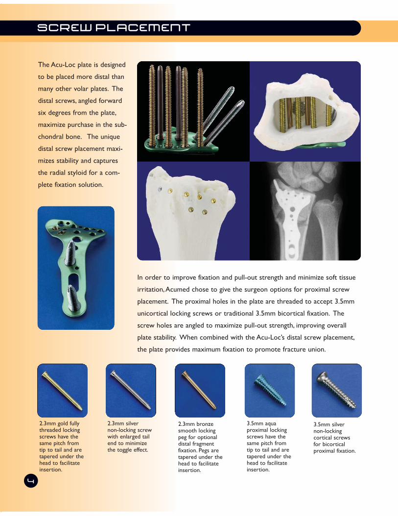
The Acu-Loc plate is designed
to be placed more distal than
many other volar plates. The
distal screws, angled forward
six degrees from the plate,
maximize purchase in the sub-
chondral bone. The unique
distal screw placement maxi-
mizes stability and captures
the radial styloid for a com-
plete fixation solution.
In order to improve fixation and pull-out strength and minimize soft tissue
irritation,Acumed chose to give the surgeon options for proximal screw
placement. The proximal holes in the plate are threaded to accept 3.5mm
unicortical locking screws or traditional 3.5mm bicortical fixation. The
screw holes are angled to maximize pull-out strength, improving overall
plate stability. When combined with the Acu-Loc’s distal screw placement,
the plate provides maximum fixation to promote fracture union.
3.5mm silver non-locking cortical screws for bicortical proximal fixation.
3.5mm aqua proximal lockingscrews have thesame pitch fromtip to tail and aretapered under thehead to facilitateinsertion.
2.3mm gold fullythreaded lockingscrews have thesame pitch fromtip to tail and aretapered under thehead to facilitateinsertion.
2.3mm silver non-locking screwwith enlarged tailend to minimizethe toggle effect.
2.3mm bronzesmooth lockingpeg for optionaldistal fragment fixation. Pegs aretapered under thehead to facilitateinsertion.
4

The Acu-Loc instrumentation system gives the surgeon a
comprehensive, complete set of instruments to implant
the plate. The system features a number of clamps,
retractors and soft tissue protectors in addition to the
drivers, drills and targeting device. Acumed’s goal is to
have one self-contained kit with everything needed for a
case, eliminating the hassle of opening other instrumenta-
tion sets for additional components.
The targeting guide has several features that contribute to an improved surgical technique for the surgeon.
The distal K-wire holes in both the targeting guide and the plate allows placement of one or more K-wires
for provisional stability and to verify the positioning of the plate. The K-wire holes are in line with the distal
screws, allowing the surgeon to verify the location of the most distal screws. The targeting guide also fea-
tures a dual hole, allowing accurate placement of the two radial styloid screws. The targeting guides are left
and right specific, with one guide to accommodate for the standard and long plates and a second guide to
accommodate the wide plate. The targeting guides are housed next to the appropriate plates in the base of
the tray for ease of use.
The Acu-Loc Targeted Distal
Radius System features a
unique targeting system for
precise drilling and screw
placement. All distal screws
can be targeted using a single
targeting guide, eliminating
the time and frustration with
traditional drilling and screw
placement techniques. The
guide allows the surgeon to
accurately and consistently
target and insert all eight dis-
tal screws.
ADVANCED INSTRUMENTATION
Dual Hole for Radial
Styloid Screws
Targeting Guide
Set Screw
Right Plate/Targeting Guide
K-Wire
Holes
Distal Targeting
Holes

ANATOMICAL DESIGN
6
The Acu-Loc plate is pre-contoured to match the anatomy of the patient. Acumed’s goal was to design a
plate that most closely replicated the anatomical contours of the distal radius in order to maximize support
and accurately reduce the fracture.
When compared to traditional T-shaped plates, the Acu-Loc addresses the key anatomical structures of the
distal radius. The shape of the plate allows it to sit more distal than many other volar plates, allowing the
screws to capture and support the subchondral bone. The distal portion of the plate has surface variations
to accommodate for the contours of the radius.
Acumed conducted extensive cadaveric research to determine how to best match the complex anatomy of
the distal radius. The plate surface is angled upward to accommodate and support the radial styloid. The
plate surface is angled back to accommodate the anatomical fluctuations of the volar-ulnar lip, which differs
from patient to patient.
Accommodates and
supports the radial
styloid.
Supports the
curvature of the
volar-ulnar lip.

BIOMECHANICAL STUDIES
7
The ability of locked screws to resist the loads in the distal radius has been shown in several studies that
compared the average construct failure load of several plates on the market. Acumed simulated the testing
methods used in these studies to determine the failure load of the Acu-Loc plate.
Biomechanical Testing
The failure load of the Acu-Loc plate was com-
pared with the results of two recent biomechani-
cal studies.
In the first study1, the biomechanical properties of
six dorsal and volar plate designs were compared
(Table 1*). Average construct failure load of the
six plates was measured. The study stated that an
estimated 250 N is the amount of force that is
applied to the wrist joint in the flexed digit posi-
tion. Testing conducted on the Acu-Loc plate
resulted in a construct load of 2400 N without
failure. This shows that the Acu-Loc can withstand
nearly 9X the force that is applied to the wrist
during patient rehabilitation. All plates, including
the Acu-Loc, exceeded this 250 N benchmark.
The six plates in the study failed in a similar fash-
ion. Bending of the plates occurred without screw
loosening.
The Acu-Loc’s biomechanical results were also
compared to the results of a second biomechani-
cal study2. In this study, the average construct fail-
ure load of three volar plate designs were com-
pared (Table 2*). Screw loosening and bending
occurred at the point of failure for the three
plates studied.
1.Osada, et. al. “Comparison of Different Distal Radius Dorsal and Volar Fracture
Fixation Plates:A Biomechanical Study”. The Journal of Hand Surgery,Vol. 28A No. 1
January 2003.
2. Osada, et. al. “Biomechanics in Uniaxial Compression of Three Distal Radius Volar
Plates”. The Journal of Hand Surgery,Vol. 29A No. 3 May 2004.
* The charts from the two studies were reproduced by Acumed with the Acu-Loc
information added for clarity.
Summary
The results of the biomechanical tests show that the Acu-Loc plate can withstand a force far beyond the
loads that are seen in the radius during patient rehabilitation.
To determine the amount
of force necessary to
cause plate failure, the
Acu-Loc plate was tested
using a similar method
described in two recent
biomechanical studies.
Table 1
Table 2

SURGICAL TECHNIQUE
Step 1: The patient’s forearm is supinated to
expose the surgical site. To maximize exposure, a
towel is placed under the wrist placing it in exten-
sion. Make a longitudinal incision approximately
six centimeters in length just radial to the FCR
tendon to protect against potential injury to the
palmar cutaneous branch of the median nerve.
Step 2: The tendon sheath is opened and the
tendon is retracted radially to protect the radial
artery. The flexor pollicus longus is identified by
passive flexion/extension of the thumb interpha-
langeal joint and is retracted ulnarly to protect
the median nerve. Next, the pronator quadratus
is identified by its transverse fibers and is released
radial to ulnar to expose the fracture site.
Step 3: The fracture is reduced and evaluated
under fluoroscopy. The brachioradialis may need
to be released from its insertion on the radial
styloid to facilitate reduction and visualization.
Step 4: There are four different plates in the set,
each with a left and right option. Left plates are
Blue, Right plates are Green. The standard plate
(PL-DR50 L/R) is usually used. However, if the
fracture extends proximally, the long plate (PL-
DR60 L/R) may be needed. If the distal radius is
wider or narrower than normal, the wide plate
(PL-DR70 L/R) or the narrow plate (PL-DR30
L/R) may be selected.
8
Standard
WideLong
ACU-LoCt TARGETED DISTAL RADIUS SYSTEM
Narrow

Step 5: Once the plate is selected, the tar-
geting guide is attached using the targeting
guide set screw (PL-DRTS) following one of
the three methods discussed. The standard
and long plates use the same targeting
guide (PL-DRT56 L/R) while the wide plate
uses a sperate guide (PL-DRT70 L/R). The
targeting guide may be attached to the
plate on the back table prior to insertion
and then placed on the bone. The plate’s
position is then secured proximally and dis-
tally with K-Wires. An alternate method is
to secure the plate to the bone with a cor-
tical screw proximally and then attach the
targeting guide. A third method is to
secure the plate to the bone with a 0.045"
K-Wire proximally and a 0.054" K-Wire
distally. The guide then slides over the dis-
tal K-Wire and into position. Care should
be taken not to angle the distal K-Wires.
Step 6: The plate is made to sit along the
distal aspect of the distal radius to support
the volar articular fracture fragments. To
temporarily hold the plate in place, a
0.045" K-Wire may be placed through one
of the small holes in the shaft of the plate.
To assess the position of the distal locking
screws relative to the articular surface, a
0.054" K-Wire may be placed through the
distal holes on the plate. The fracture
reduction, position of the plate, and the
location of the distal K-Wire relative to
the joint is assessed under fluoroscopy. If
the distal K-Wire does not penetrate the
joint, the subsequent distal locking screws
will not as well. Care should be taken that
there is no soft tissue in the targeting
guide.
9
William B. Geissler, M.D.

Step 7: Place the first 3.5mm cortical
screw through the slot in the plate. The
position of the plate relative to the articu-
lar surface can then be fine tuned by sliding
the plate proximal or distal under fluo-
roscopy. Using the 2.8mm drill (MS-DC28)
and the drill guide (PL-2018), drill through
the far cortex. Drill depth is measured
with the depth gauge (MS-9020). Note
that if provisional K-Wires are in place,
they may interfere with drilling and screw
insertion. Insert the appropriate silver
3.5mm screw (CO-3xx0), taking care that
the screw does not exit the bone dorsally.
Step 8: Select one of the four screws
closest to the joint to target first. There
are three types of screws that can be used
in any of the eight distal holes: Fully-
Threaded Locking Screws, Smooth Locking
Pegs and Non-Toggling Screws. Insert the
drill guide (MS-DG23) into one of the
holes, followed by the 2.0mm drill (MS-
DCR20).
SURGICAL TECHNIQUE
10
ACU-LoCt TARGETED DISTAL RADIUS SYSTEM

Step 9: The depth of the screw is mea-
sured using the laser mark on the shaft of
the drill and the scale on the drill guide.
An alternative way to measure the screw
length is by using the Depth Probe (MS-
DRPB). The probe is inserted through the
drill guide, hooking the far cortex. The
screw length measurement is read from
the laser mark on the probe. Both the
probe and the drill guide are removed
together prior to screw insertion.
Step 10: A Gold Threaded Locking Screw
(CO-T23xx) is inserted using the 1.5mm
driver tip (HPC-0015), sleeve (MS-SS23)
and driver handle (MS-2210). A Bronze
Smooth Locking Peg (CO-S23xx), or a
Silver Non-Locking Screw (CO-N23xx)
may also be used.
An alternative method to drilling the distal
screws is available with the Acu-Loc plate.
An Individual Locking Drill Guide (MS-
LDG23) is available in the system that
threads into the eight distal locking holes
individually. Screw length can be read using
the Depth Gauge (MS-9020).
11
William B. Geissler, M.D.
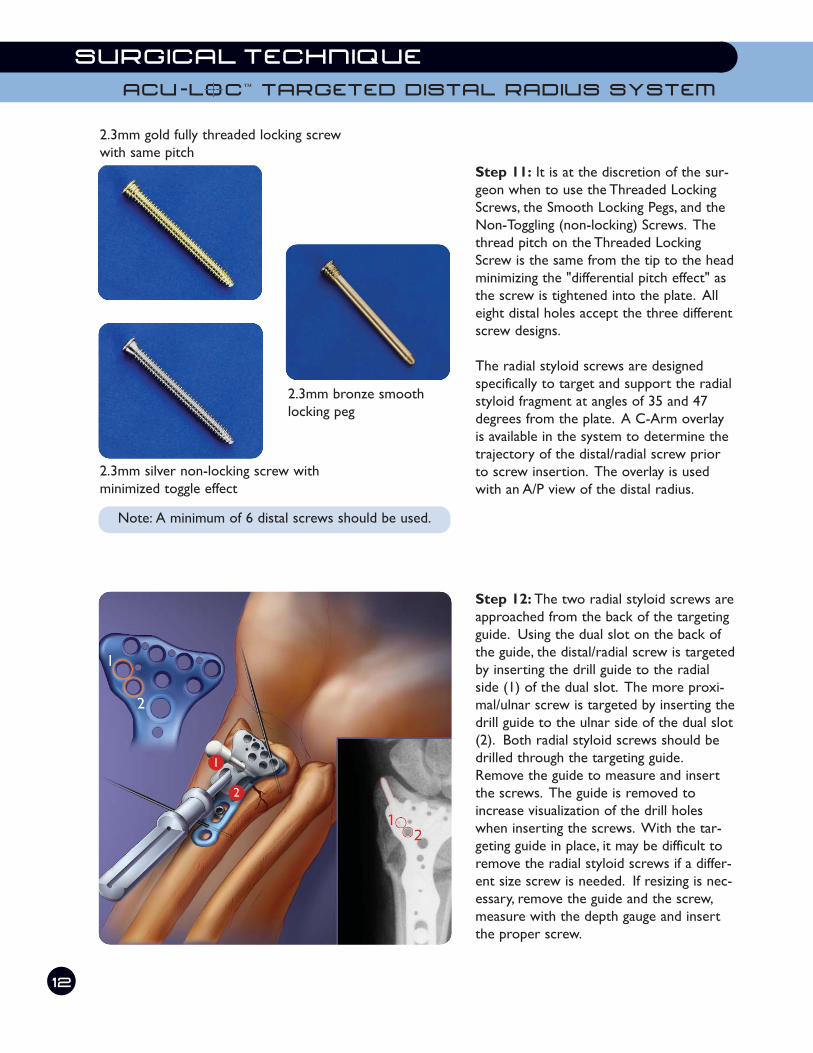
Step 11: It is at the discretion of the sur-
geon when to use the Threaded Locking
Screws, the Smooth Locking Pegs, and the
Non-Toggling (non-locking) Screws. The
thread pitch on the Threaded Locking
Screw is the same from the tip to the head
minimizing the "differential pitch effect" as
the screw is tightened into the plate. All
eight distal holes accept the three different
screw designs.
The radial styloid screws are designed
specifically to target and support the radial
styloid fragment at angles of 35 and 47
degrees from the plate. A C-Arm overlay
is available in the system to determine the
trajectory of the distal/radial screw prior
to screw insertion. The overlay is used
with an A/P view of the distal radius.
Step 12: The two radial styloid screws are
approached from the back of the targeting
guide. Using the dual slot on the back of
the guide, the distal/radial screw is targeted
by inserting the drill guide to the radial
side (1) of the dual slot. The more proxi-
mal/ulnar screw is targeted by inserting the
drill guide to the ulnar side of the dual slot
(2). Both radial styloid screws should be
drilled through the targeting guide.
Remove the guide to measure and insert
the screws. The guide is removed to
increase visualization of the drill holes
when inserting the screws. With the tar-
geting guide in place, it may be difficult to
remove the radial styloid screws if a differ-
ent size screw is needed. If resizing is nec-
essary, remove the guide and the screw,
measure with the depth gauge and insert
the proper screw.
SURGICAL TECHNIQUE
12
2.3mm gold fully threaded locking screw
with same pitch
2.3mm silver non-locking screw with
minimized toggle effect
2.3mm bronze smooth
locking peg
ACU-LoCt TARGETED DISTAL RADIUS SYSTEM
Note: A minimum of 6 distal screws should be used.

Step 13: Select one of the two remaining
proximal holes and insert the Threaded
Drill Guide (MS-LDG35) if a locking screw
is desired, or the Standard Drill Guide (PL-
2018) if a non-locking screw is needed.
Drill with the 2.8mm drill (MS-DC28) for
either proximal screw.
Step 14: Drill depth is measured with the
depth gauge (MS-9020). Insert the appro-
priate Light Blue 3.5mm Locking Screw
(COL-3xx0), taking care that the screw
does not exit the bone dorsally. Insert the
locking screw using the 2.5mm driver tip
(HPC-0025), sleeve (MS-SS35) and driver
handle (MS-3200). Using the same process,
drill and place the final locking screw.
13
William B. Geissler, M.D.
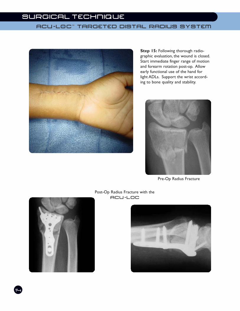
Step 15: Following thorough radio-
graphic evaluation, the wound is closed.
Start immediate finger range of motion
and forearm rotation post-op. Allow
early functional use of the hand for
light ADLs. Support the wrist accord-
ing to bone quality and stability.
SURGICAL TECHNIQUE
14
ACU-LoCt TARGETED DISTAL RADIUS SYSTEM
Pre-Op Radius Fracture
Post-Op Radius Fracture with the
ACU-LOC

Precise Screw Placement enables the surgeon to maximize pur-
chase in the distal radius and the radial styloid. Unicortical locking
proximal screws provide stability while eliminating soft tissue impinge-
ment on the dorsal surface of the distal radius.
Advanced Targeting Guide allows the surgeon to quickly target each of
the eight distal screws, saving valuable O.R. time and frustration associated
with individual targeting guides.
Anatomical Plate Design assists in restoring the original geometry
of the patient's anatomy. Extensive cadaveric research aided in the
development of an anatomically contoured plate design. Left and Right
specific plate options are available in the system that each precisely
match the anatomical curvature of the distal radius.
Distal row of
screws/pegs.
Color coded for left (blue) and right (green) application.
Targeted radial styloid screws.
K-wire holes for
provisional stability.
Reduction slot.Static holes for proximal
locking screws.
Mounting hole for targeting guide.
Beveled plate edges to
minimize irritation.
Low profile plate/screw interface.
3
K-wire holes for provisional stability and to ensure
screws do not pass through the radial-carpal joint.
Proximal row of
screws/pegs stagger
between distal row to
maximize stability.
Targeting guide alignment hole.
Titanium Alloy

With the Acu-Loc Targeted Distal Radius Plate, Acumed has designed an inno-
vative solution for repairing fractures of the distal radius. Both the Acu-Loc
plate and the instrumentation system contain several key features that address
the issues faced with other plating techniques. Acumed recognized these
issues and designed a solution that attends to these difficulties while also
embracing innovation.
When designing the Acu-Loc plates,Acumed’s goal was to design a better
implant for the patient while improving the overall procedure for the sur-
geon. The anatomic design of the titanium plate, in conjunction with precise
screw positioning and locking capabilities, creates an extremely stable con-
struct with minimal soft tissue irritation. The unique targeting device mini-
mizes O.R. time and improves the surgical technique.
ACU-LoCtTargeted Distal Radius System
Since 1988 Acumed has beendesigning solutions to thedemanding situations facingorthopedic surgeons, hospitalsand their patients. Our strategy has been to know theindication, design a solution tofit, and deliver quality products and instruments.
In a continuing effort to advance
orthopedics,Acumed introduces
the Acu-Loc Targeted Distal
Radius Plate. The plate has sev-
eral key features that contribute
to an overall stable construct,
ultimately benefiting the patient.
Our goal was to design a plate
that incorporated both a locking
construct and a screw trajectory
that maximized purchase in the
distal fragments, with a targeting
guide that aided the surgeon and
improved the surgical technique.
The launch of the Acu-Loc plate
and its comprehensive, unique
instrumentation system brings to
orthopedics an advancement in
the treatment of distal radius
fractures. The implants and
instruments are an extension of
Acumed’s philosophy to bring to
the market an innovative prod-
uct that addresses the issues
with current treatment methods
for a specific indication.
Acumed’s precise screw position-
ing and angulation targets the dis-
tal fragments and provides secure,
stable fracture fixation. Two of the
distal screws specifically target the
radial styloid to provide fixation
along the entire distal radius. The
screw positioning ensures that
most fragments can be captured
by a locking or non-locking screw.
2
AC
U-L
oC
tT
AR
GE
TE
D D
IST
AL
R
AD
IUS
S
YS
TE
M
AAccuu--LLoocc DDiissttaall RRaaddiiuuss PPllaatteess 22..33mmmm SSmmooootthh PPeeggPL-DR50L Standard Distal Radius Plate - Left CO-S2314 2.3mm Peg 14mm LongPL-DR50R Standard Distal Radius Plate - Right CO-S2316 2.3mm Peg 16mm LongPL-DR60L Long Distal Radius Plate - Left CO-S2318 2.3mm Peg 18mm LongPL-DR60R Long Distal Radius Plate - Right CO-S2320 2.3mm Peg 20mm LongPL-DR70L Wide Distal Radius Plate - Left CO-S2322 2.3mm Peg 22mm LongPL-DR70R Wide Distal Radius Plate - Right CO-S2324 2.3mm Peg 24mm LongPL-DR30L Narrow Distal Radius Plate - Left CO-S2326 2.3mm Peg 26mm LongPL-DR30R Narrow Distal Radius Plate - Right CO-S2328 2.3mm Peg 28mm Long
DDrriillll BBiittss 22..33mmmm TThhrreeaaddeedd LLoocckkiinngg SSccrreewwMS-DC28 2.8 mm Drill Bit CO-T2314 2.3mm Threaded Locking Screw 14mm LongMS-DCR20 2.0 mm Drill Bit CO-T2316 2.3mm Threaded Locking Screw 16mm Long
CO-T2318 2.3mm Threaded Locking Screw 18mm LongCO-T2320 2.3mm Threaded Locking Screw 20mm Long
KK--WWiirreess && DDrriillll GGuuiiddeess CO-T2322 2.3mm Threaded Locking Screw 22mm LongWS-1106 .045 K-Wire CO-T2324 2.3mm Threaded Locking Screw 24mm LongWS-1406 .054 K-Wire CO-T2326 2.3mm Threaded Locking Screw 26mm LongMS-LDG23 Locking Drill Guide - Distal CO-T2328 2.3mm Threaded Locking Screw 28mm LongMS-LDG35 Locking Drill Guide - Proximal
22..33mmmm TThhrreeaaddeedd NNoonn--TToogggglliinngg SSccrreewwCO-N2314 2.3mm Non-Toggling Screw 14mm Long
33..55mmmm CCoorrttiiccaall SSccrreewwss CO-N2316 2.3mm Non-Toggling Screw 16mm LongCO-3100 3.5mm Cortical Screw 10mm Long CO-N2318 2.3mm Non-Toggling Screw 18mm LongCO-3120 3.5mm Cortical Screw 12mm Long CO-N2320 2.3mm Non-Toggling Screw 20mm LongCO-3140 3.5mm Cortical Screw 14mm Long CO-N2322 2.3mm Non-Toggling Screw 22mm LongCO-3160 3.5mm Cortical Screw 16mm Long CO-N2324 2.3mm Non-Toggling Screw 24mm LongCO-3180 3.5mm Cortical Screw 18mm Long CO-N2326 2.3mm Non-Toggling Screw 26mm Long
CO-N2328 2.3mm Non-Toggling Screw 28mm Long33..55mmmm LLoocckkiinngg CCoorrttiiccaall SSccrreewwss CO-N2330 2.3mm Non-Toggling Screw 30mm LongCOL-3080 3.5mm Locking Cortical Screw 8mm Long CO-N2332 2.3mm Non-Toggling Screw 32mm LongCOL-3100 3.5mm Locking Cortical Screw 10mm LongCOL-3120 3.5mm Locking Cortical Screw 12mm LongCOL-3140 3.5mm Locking Cortical Screw 14mm LongCOL-3160 3.5mm Locking Cortical Screw 16mm LongCOL-3180 3.5mm Locking Cortical Screw 18mm Long
15
AcUMEDr5885 NW Cornelius Pass Road,Hillsboro,OR 97124(888) 627-9957www.acumed.net
(glu
e f
lap)
ACU-LoCtTARGETED DISTAL RADIUS SYSTEM
AcUMEDr
5885 N.W. Cornelius Pass Road
Hillsboro, OR 97124-9432
(888) 627-9957
www.acumed.net
Distributed by:
CPS00-03-02 Effective: 9/2005
Copyright © 2005
Acumed is a registered trademark.
All rights reserved.
Patents pending.