5.7.6 st peters interchange portal · pdf file7.06.2015 · 5.7.6 st peters...
TRANSCRIPT

New M5 WestConnex Urban Design Urban Design96
5.7.6 St Peters Interchange Portal
Design intentAt St Peters interchange the design approach to the tunnel portals differs from that adopted for the western portals at Kingsgrove. An entirely different set of circumstances occurs at the interchange. Here,aformerlandfillwouldbetransformed into a vibrant new interchange parkland,significantlyincreasingvegetationcoverage with new passive recreation areas for the local community. The new infrastructure elements within the interchange need to ‘sit within’ and be integrated with the parklands as opposed to being imposed upon them.
The design provides a simple and elegant solutionthatunifiesarangeofgeologicalissues by wrapping the portal and approaches in a giant ‘sculptural veil’ form. The veil provides a light and lyrical element that would read as a sculpture within the overall interchange parkland. This approach could be adopted for the future M4-M5 Link portals adjacent to Campbell Street.
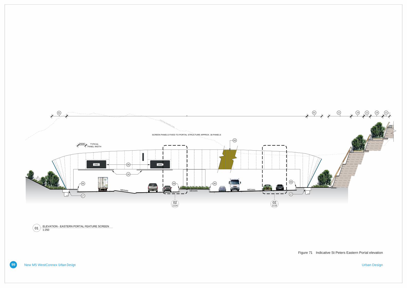
Materials, colours and finishesThe ‘sculptural veil’ is a series of coloured rectangular aluminium sections laid in a curvilinear series at varying angles to establish a seemingly continuous, but transparent, sinuous form. It presents a unique and memorable experience for drivers entering and exiting the tunnel and also for the local community and park users who would be able to view the portals from various elevated viewpoints.
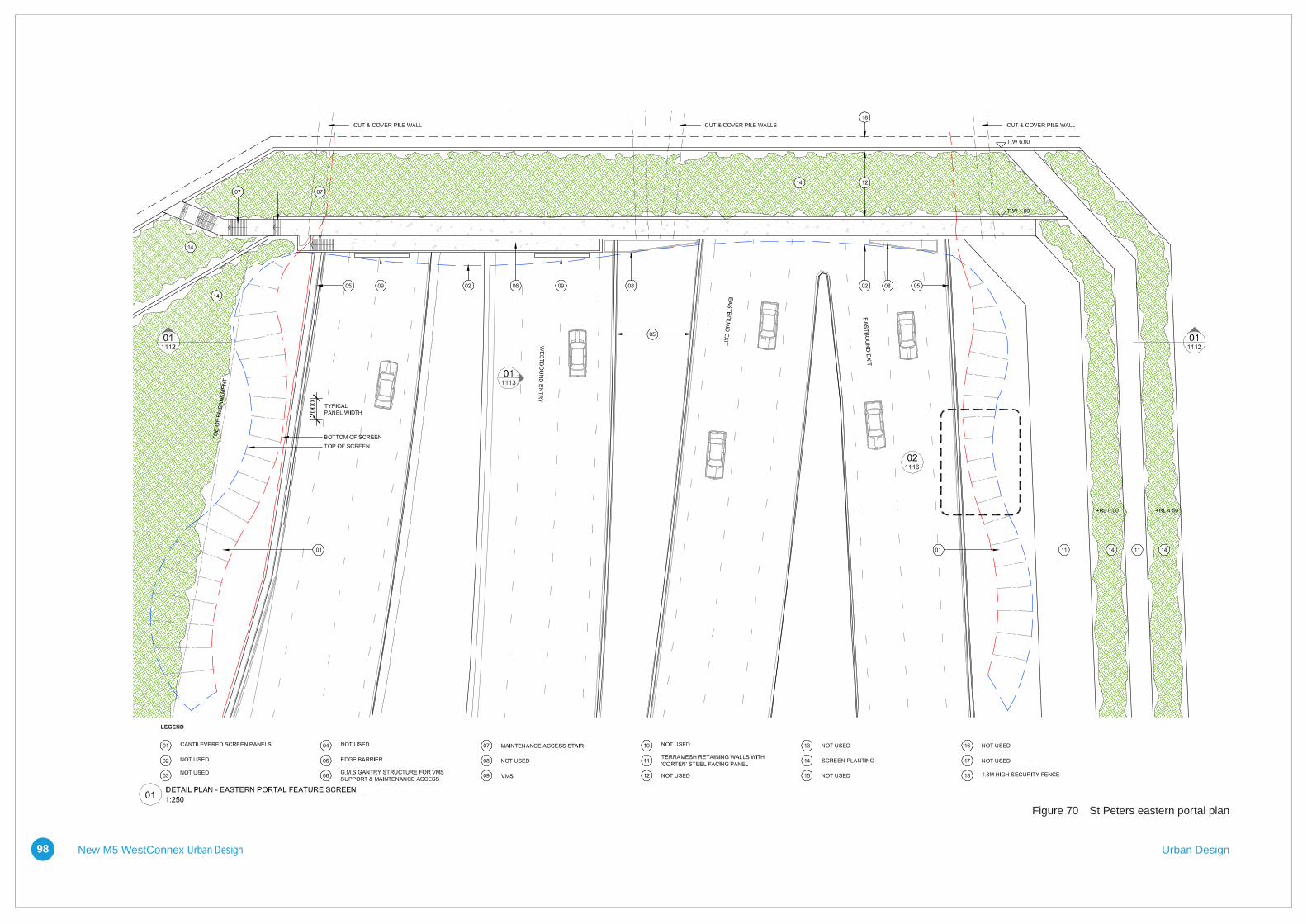
The veil would also include LED feature lighting using a programmable system to provide a range of lighting effects adding to the night-time experience. Variable message signs (VMS), lane signals and the like would be integrated in the design with service and maintenance access via a gantry behind the veil. Above the portal would be a series of retaining walls and terraces to support the installation of new soilprofilesintheorderofonemetredeep,capable of supporting new parkland vegetation. The following pages provide preliminary plans, perspectives and sections of the portal. These would be further developed during detailed design.

New M5 WestConnex Urban Design Urban Design9737
VOLUME 2 (p) ST PETERS INTERCHANGE
Response to Tender • DESIGN AND CONSTRUCTION OF NEW M5 MAIN WORKS • Contract No. 14.7205.1875
ARTISTS IMPRESSION - ST PETERS TUNNEL PORTAL
ARTISTS IMPRESSION - ST PETERS TUNNEL PORTAL
Figure 69 Artist’s impression - St Peters Tunnel Portal
New M5 WestConnex Urban Design Urban Design98 38WESTCONNEX | NEW M5 MAIN WORKS
URBAN AND LANDSCAPE DESIGN
VOLUME 2 (p) ST PETERS INTERCHANGE
01 - ST PETERS EASTERN PORTAL - CONCEPT PLAN 1:250 @ A3Figure 70 St Peters eastern portal plan
New M5 WestConnex Urban Design Urban Design99
39 Response to Tender • DESIGN AND CONSTRUCTION OF NEW M5 MAIN WORKS • Contract No. 14.7205.1875
VOLUME 2 (p) ST PETERS INTERCHANGE
MEDIANMEDIAN
VMSVMS
12
MEDIAN
2000 TYPICALPANEL WIDTH
SCREEN PANELS FIXED TO PORTAL STRUCTURE APPROX. 30 PANELS
01 01
03
0505 0505
1717
09
16
EXISTING GROUND LEVEL
11 14 11 14 11
LEGEND
CANTILEVERED SCREEN PANELS
03
04
05
06
07
08
09
10
11
01
02 NOT USED
160 x 100 RHS ALUMINUM BATTENS WITH SELECTEPOXY FINISH
NOT USED
EDGE BARRIER
NOT USED
NOT USED
NOT USED
VMS
NOT USED
TERRAMESH RETAINING WALLS WITH 'CORTEN'STEEL FACING PANEL
12 NOT USED
13 NOT USED
14 SCREEN PLANTING
15 NOT USED
16 OVERHEIGHT PROTECTION BARRIER
17 FOOTING TO ENGINEERS DETAIL
18 NOT USED
0 5 10 15 20 25 mm ON A3 ORIGINALDESCRIPTIONDATEREV APPROVAL
ORIGINAL DRAWING AT A3 SIZE
REVIEWED
DRAWING NUMBER REV
STATUS
DRAFTSPERSON
DRAFTING CHECK
DESIGNER
DESIGN CHECK
DESIGN MANAGER
INITIAL DATETITLE
CO-ORDINATE SYSTEM: MGA Zone 56 HEIGHT DATUM: A.H.D.
This Drawing may have been prepared using colour and may be incomplete if copied
NEW M5 MAIN WORKS DESIGN & CONSTRUCT
DRAWN
PROJECT
RFT APP.2 - TENDER INFORMATION REQUIREMENTS VOLUME
DATE
: 6/07
/2015
12:14
:54 P
MLO
GIN
NAME
: JAS
ON C
UFFE
LOCA
TION
: \\sy
dpro
j\fs03
\0109
62-6
1A-P
\Wor
king\A
utoCA
D\Sh
eet\0
2. TU
NNEL
\M5
HAS
DWG
UD_S
PI E
ASTE
RN P
ORTA
L.dwg
TITLE
PROJECT DIRECTOR
WESTCONNEX STAGE 2LEIGHTON DRAGADOS SAMSUNG C&T JOINT VENTURE
INFORMATION SHOWN ON THIS DRAWING IS PRELIMINARY ONLYAND SUBJECT TO ADJUSTMENT DURING DETAILED DESIGN STAGE.
3.75m2.501.25 1.25
1 : 250 FULL SIZE A3
ELEVATION - EASTERN PORTAL FEATURE SCREEN1:250
021114
021115
01
ELEVATIONPMMGJSISSUED TO REFLECT POST-TENDER ADDENDUM 110-07-151
NOT ISSUED27-03-15010-07-15PC
10-07-15PM
10-07-15MG
10-07-15JS
10-07-15MG
10-07-15JS
2P - URBAN AND LANDSCAPE DESIGN
NOT FOR CONSTRUCTION
SPI EASTERN PORTALURBAN AND LANDSCAPE DESIGN
PROJECT WIDE
1M5-HAS-DWG-700-810-UD-7110
CONCEPT DESIGN
02 - ST PETERS EASTERN PORTAL - ELEVATION 1:250 @ A3
MEDIANMEDIAN
VMSVMS
12
MEDIAN
2000 TYPICALPANEL WIDTH
SCREEN PANELS FIXED TO PORTAL STRUCTURE APPROX. 30 PANELS
01 01
03
0505 0505
1717
09
16
EXISTING GROUND LEVEL
11 14 11 14 11
LEGEND
CANTILEVERED SCREEN PANELS
03
04
05
06
07
08
09
10
11
01
02 NOT USED
160 x 100 RHS ALUMINUM BATTENS WITH SELECTEPOXY FINISH
NOT USED
EDGE BARRIER
NOT USED
NOT USED
NOT USED
VMS
NOT USED
TERRAMESH RETAINING WALLS WITH 'CORTEN'STEEL FACING PANEL
12 NOT USED
13 NOT USED
14 SCREEN PLANTING
15 NOT USED
16 OVERHEIGHT PROTECTION BARRIER
17 FOOTING TO ENGINEERS DETAIL
18 NOT USED
0 5 10 15 20 25 mm ON A3 ORIGINALDESCRIPTIONDATEREV APPROVAL
ORIGINAL DRAWING AT A3 SIZE
REVIEWED
DRAWING NUMBER REV
STATUS
DRAFTSPERSON
DRAFTING CHECK
DESIGNER
DESIGN CHECK
DESIGN MANAGER
INITIAL DATETITLE
CO-ORDINATE SYSTEM: MGA Zone 56 HEIGHT DATUM: A.H.D.
This Drawing may have been prepared using colour and may be incomplete if copied
NEW M5 MAIN WORKS DESIGN & CONSTRUCT
DRAWN
PROJECT
RFT APP.2 - TENDER INFORMATION REQUIREMENTS VOLUME
DATE
: 6/07
/2015
12:14
:54 P
MLO
GIN
NAME
: JAS
ON C
UFFE
LOCA
TION
: \\sy
dpro
j\fs03
\0109
62-6
1A-P
\Wor
king\A
utoCA
D\Sh
eet\0
2. TU
NNEL
\M5
HAS
DWG
UD_S
PI E
ASTE
RN P
ORTA
L.dwg
TITLE
PROJECT DIRECTOR
WESTCONNEX STAGE 2LEIGHTON DRAGADOS SAMSUNG C&T JOINT VENTURE
INFORMATION SHOWN ON THIS DRAWING IS PRELIMINARY ONLYAND SUBJECT TO ADJUSTMENT DURING DETAILED DESIGN STAGE.
3.75m2.501.25 1.25
1 : 250 FULL SIZE A3
ELEVATION - EASTERN PORTAL FEATURE SCREEN1:250
021114
021115
01
ELEVATIONPMMGJSISSUED TO REFLECT POST-TENDER ADDENDUM 110-07-151
NOT ISSUED27-03-15010-07-15PC
10-07-15PM
10-07-15MG
10-07-15JS
10-07-15MG
10-07-15JS
2P - URBAN AND LANDSCAPE DESIGN
NOT FOR CONSTRUCTION
SPI EASTERN PORTALURBAN AND LANDSCAPE DESIGN
PROJECT WIDE
1M5-HAS-DWG-700-810-UD-7110
CONCEPT DESIGN
Figure 71 Indicative St Peters Eastern Portal elevation

New M5 WestConnex Urban Design Urban Design100 40WESTCONNEX | NEW M5 MAIN WORKS
URBAN AND LANDSCAPE DESIGN
VOLUME 2 (p) ST PETERS INTERCHANGE
G.L 0.00
G.L 4.50
G.L 9.00
1000
1000
1000
TOP OF FACING PANEL
2000 TYPICALPANEL WIDTH
SHARED USER PATH
SHARED USER PATH
010301 05
06
13
1309
16
10
11
12
18
15
14
TRANSITION FEATURE SCREEN PANELSSTANDARD LINING PANELS
EXISTING GROUND LEVEL
LEGEND
CANTILEVERED SCREEN PANELS
03
04
05
06
07
08
09
10
11
01
02 SCREEN PANELS FIXED TO PORTAL STRUCTURE
160 x 100 RHS ALUMINUM BATTENS WITH SELECTEPOXY FINISH
BASEPLATE
EDGE BARRIER
G.M.S GANTRY STRUCTURE FOR VMS SUPPORT &MAINTENANCE ACCESS
MAINTENANCE ACCESS STAIR
G.M.S SCREEN PANEL SUPPORTING FRAME
VMS
SUPER 'T' GIRDER
TERRAMESH RETAINING WALLS WITH 'CORTEN'STEEL FACING PANEL
12 R.C. RETAINING WALLS
13 R.C. SLAB
14 SCREEN PLANTING
15 SELECT SOIL MIX & DRAINAGE
16 OVERHEIGHT PROTECTION BARRIER
17 FOOTING TO ENGINEERS DETAIL
18 1.8M HIGH SECURITY FENCE
0 5 10 15 20 25 mm ON A3 ORIGINALDESCRIPTIONDATEREV APPROVAL
ORIGINAL DRAWING AT A3 SIZE
REVIEWED
DRAWING NUMBER REV
STATUS
DRAFTSPERSON
DRAFTING CHECK
DESIGNER
DESIGN CHECK
DESIGN MANAGER
INITIAL DATETITLE
CO-ORDINATE SYSTEM: MGA Zone 56 HEIGHT DATUM: A.H.D.
This Drawing may have been prepared using colour and may be incomplete if copied
NEW M5 MAIN WORKS DESIGN & CONSTRUCT
DRAWN
PROJECT
RFT APP.2 - TENDER INFORMATION REQUIREMENTS VOLUME
DATE
: 6/07
/2015
12:14
:58 P
MLO
GIN
NAME
: JAS
ON C
UFFE
LOCA
TION
: \\sy
dpro
j\fs03
\0109
62-6
1A-P
\Wor
king\A
utoCA
D\Sh
eet\0
2. TU
NNEL
\M5
HAS
DWG
UD_S
PI E
ASTE
RN P
ORTA
L.dwg
TITLE
PROJECT DIRECTOR
WESTCONNEX STAGE 2LEIGHTON DRAGADOS SAMSUNG C&T JOINT VENTURE
INFORMATION SHOWN ON THIS DRAWING IS PRELIMINARY ONLYAND SUBJECT TO ADJUSTMENT DURING DETAILED DESIGN STAGE.
3.75m2.501.25 1.25
1 : 250 FULL SIZE A3
3.75m2.501.25 1.25
1 : 250 FULL SIZE A3
SECTION ELEVATION - EASTERN PORTAL FEATURE SCREEN1:250
3.75m2.501.25 1.25
1 : 250 FULL SIZE A3
SECTION ELEVATION - EASTERN PORTAL FEATURE SCREEN1:250
011114
01
SECTION ELEVATIONPMMGJSISSUED TO REFLECT POST-TENDER ADDENDUM 110-07-151
NOT ISSUED27-03-15010-07-15PC
10-07-15PM
10-07-15MG
10-07-15JS
10-07-15MG
10-07-15JS
2P - URBAN AND LANDSCAPE DESIGN
NOT FOR CONSTRUCTION
SPI EASTERN PORTALURBAN AND LANDSCAPE DESIGN
PROJECT WIDE
1M5-HAS-DWG-700-810-UD-7111
CONCEPT DESIGN
03 - ST PETERS EASTERN PORTAL - SECTION ELEVATION 1:250 @ A3
Figure 72 Indicative St Peters Eastern Portal elevation

New M5 WestConnex Urban Design Urban Design101
5.7.7 BridgesThe interchange includes a total of six road bridges and these would form a notable feature within the interchange landscape. Attention has been paid to the design detailing of these road bridges to ensure an elegant and minimalist form. Within the interchange itself the bridges would be stacked, providing connectivity between the St Peters portal, future M4-M5 Link portal, future Sydney Gateway, the New M5 ramps to Euston and Campbell Roads and Gardeners Road. To accommodate these connections the bridges would be layered in 4 levels. With mass planting in the interchange the scale of the road bridges would be tempered.
Design intentThe design approach to bridges in the interchange must carefully consider their forms,spans,profile,finishesandpierrhythm in conjunction with well-coordinated detailing. The architectural treatment of the bridges is considered paramount with clean lines and incorporating piers and abutments sympathetic to the structural form.
The bridges would have architecturally profileddecksoffitsandbarrieredgestoensureanelegantfinishbefittingthecriticalimportance of the iconic interchange. Feature lighting would also be included to highlight key elements of the structures.
Within the interchange there are a number of feature bridges that would provide new connections:
1. Campbell Road bridge over Alexandra Canal
A dedicated road bridge would be constructed, continuing the alignment of Campbell Road east over the Alexandra Canal connecting to Bourke Road (the Campbell Road bridge). The bridge would span the entire canal and allow for two eastboundandtwowestboundtrafficlanes. In addition a shared cycle and pedestrian path would be included on the northern side of the bridge and a footpath on the southern side.
The Alexandra Canal is a state heritage listed item owing to its rarity as one of only twoartificialcanalsconstructedinNSW.The design of the bridge respects the value of the canal by ensuring a clear span over the waterway.
The clear span is designed to avoid disturbing the highly contaminated Alexandra Canal bed sediments. The bridge superstructure span is made up of six steel trough girders with a cast in-situ concrete deck. The continuous spans are designed to reduce the depth of the superstructure to minimise embankment height.
Figure 73 Artist impression of Campbell Road bridge

39WESTCONNEX | NEW M5 MAIN WORKS
URBAN AND LANDSCAPE DESIGN
VOLUME 2 (p) APPENDIX A
ALEXANDRA CANAL
APPROACH SLAB
REINFORCED CONCRETE PIER
BRIDGE ABUTMENT
SHARED PATH
MEDIAN
APPROXIMATE EXISTING SURFACE LEVEL
LEGEND
2650 DEEP STEEL TROUGH GIRDER
FOOTPATH
TWIN RAIL SAFETY BARRIER
PEDESTRIAN SAFETY FENCE
BRIDGE DECK
01 CAMPBELL ROAD BRIDGE OVER ALEXANDRA CANAL - PLAN1:500
02 CAMPBELL ROAD BRIDGE OVER ALEXANDRA CANAL - ELEVATION1:500
03 CAMPBELL ROAD BRIDGE OVER ALEXANDRA CANAL - SECTION1:200
03
02
ALEXANDRA CANAL
CAMPBELL ROAD
N
BRIDGES - CAMPBELL STREET BRIDGE OVER ALEXANDRA CANAL 1:200 / 1:500 @ A3
ALEXANDRA CANAL
APPROACH SLAB
REINFORCED CONCRETE PIER
BRIDGE ABUTMENT
SHARED PATH
MEDIAN
APPROXIMATE EXISTING SURFACE LEVEL
LEGEND
2650 DEEP STEEL TROUGH GIRDER
FOOTPATH
TWIN RAIL SAFETY BARRIER
PEDESTRIAN SAFETY FENCE
BRIDGE DECK
01 CAMPBELL ROAD BRIDGE OVER ALEXANDRA CANAL - PLAN1:500
02 CAMPBELL ROAD BRIDGE OVER ALEXANDRA CANAL - ELEVATION1:500
03 CAMPBELL ROAD BRIDGE OVER ALEXANDRA CANAL - SECTION1:200
03
02
ALEXANDRA CANAL
CAMPBELL ROAD
N
New M5 WestConnex Urban Design Urban Design102
Figure 74 Indicative plan Campbell Road bridge over Alexandra Canal

New M5 WestConnex Urban Design Urban Design103
2. Gardeners Road Bridge over Alexandra Canal
The Gardeners Road bridge would provide an easterly connection for vehicles travelling north on the New M5. Gardeners Road bridge would provide the main eastbound route from the interchange.
The design of Gardeners Road bridge would feature a clear span over water and would be similar in overall appearance to the Campbell Road bridge. It would have a similar pier shape, span, barrier/edge details and abutments so that the two bridges read as a suite.
95 Response to Tender • DESIGN AND CONSTRUCTION OF NEW M5 MAIN WORKS • Contract No. 14.7205.1875
VOLUME 2 (p) ST PETERS INTERCHANGE
BRIDGES - GARDENERS ROAD BRIDGE OVER ALEXANDRA CANAL 1:1000 @ A3
Figure 75 Indicative Gardeners Road bridge over Alexandra Canal