544.1r-96 state-of-the-art report on fiber reinforced concreteindiafiber.com/files/aci...
TRANSCRIPT

The report prepared by ACI Committee 544 on Fiber Reinforced Concrete(FRC) is a comprehensive review of all types of FRC. It includes fundamentalprinciples of FRC, a glossary of terms, a description of fiber types, manufac-turing methods, mix proportioning and mixing methods, installation prac-tices, physical properties, durability, design considerations, applications,and research needs. The report is broken into five chapters: Introduction,
Steel FRC, Glass FRC, Synthetic FRC, and Natural FRC.
Fiber reinforced concrete (FRC) is concrete made primarily of hydrauliccements, aggregates, and discrete reinforcing fibers. Fibers suitable for rein-forcing concrete have been produced from steel, glass, and organic polymers(synthetic fibers). Naturally occurring asbestos fibers and vegetable fibers,such as sisal and jute, are also used for reinforcement. The concrete matricesmay be mortars, normally proportioned mixes, or mixes specifically formu-lated for a particular application. Generally, the length and diameter of thefibers used for FRC do not exceed 3 in. (76 mm) and 0.04 in. (1 mm), respec-tively. The report is written so that the reader may gain an overview of theproperty enhancements of FRC and the applications for each general cate-gory of fiber type (steel, glass, synthetic, and natural fibers).
Brittle materials are considered to have no significant post-cracking ductility.Fibrous composites have been and are being developed to provide improvedmechanical properties to otherwise brittle materials. When subjected to ten-
ACI 544.1R-96
Report on Fiber Reinforced ConcreteReported by ACI Committee 544
James I. Daniel*
ChairmanVellore S. Gopalaratnam
SecretaryMelvyn A. Galinat
Membership Secretary
Shuaib H. Ahmad George C. Hoff Morris Schupack
M. Arockiasamy Roop L. Jindal Surendra P. Shah‡‡
P. N. Balaguru** Colin D. Johnston George D. Smith
Hiram P. Ball, Jr. Mark A. Leppert Philip A. Smith
Nemkumar Banthia Clifford N. MacDonald Parvis Soroushian
Gordon B. Batson Pritpal S. Mangat James D. Speakman
M. Ziad Bayasi Henry N. Marsh, Jr.†† David J. Stevens
Marvin E. Criswell Nicholas C. Mitchell R. N. Swamy
Daniel P. Dorfmueller Henry J. Molloy‡ Peter C. Tatnall†
Marsha Feldstein D. R. Morgan Ben L. Tilsen
Antonio V. Fernandez A. E. Naaman George J. Venta§§
Sidney Freedman Antonio Nanni Gary L. Vondran
David M. Gale Seth L. Pearlman* Methi Wecharatana
Antonio J. Guerra** Max L. Porter Spencer T. Wu
Lloyd E. Hackman V. Ramakrishnan Robert C. Zellers
C. Geoffrey Hampson Ken Rear Ronald F. Zollo§
M. Nadim Hassoun D. V. Reddy
Carol D. Hays Ernest K. Schrader* Cochairmen, State-of-the-Art Subcommittee; responsible for preparing Chapter 1 and coordinating the entire report.† Chairman, Steel Fiber Reinforced Concrete Subcommittee; responsible for preparing Chapter 2.‡ Chairman, Glass Fiber Reinforced Concrete Subcommittee; responsible for perparing Chapter 3.§ Chairman, Synthetic Fiber Reinforced Concrete Subcommittee; responsible for preparing Chapter 4.** Cochairmen, Natural Fiber Reinforced Concrete Subcommittee; responsible for preparing Chapter 5.†† Chairman, Editorial Subcommittee; responsible for reviewing and final editing the entire report.‡‡ Previous Chairman of Committee 544; responsible for overseeing the development of the majority of this State-of-the-Art Report.§§ Previous Chairman of Glass Fiber Reinforced Concrete Subcommittee; responsible for overseeing the development of much of Chapter 3.
ACI Committee reports, guides, standard practices, designhandbooks, and commentaries are intended for guidance inplanning, designing, executing, and inspecting construction.This document is intended for the use of individuals who arecompetent to evaluate the significance and limitations of itscontent and recommendations and who will accept responsibil-ity for the application of the material it contains. The AmericanConcrete Institute disclaims any and all responsibility for theapplication of the stated principles. The Institute shall not be li-able for any loss or damage arising therefrom. Reference to this document shall not be made in contract doc-uments. If items found in this document are desired by the Ar-chitect/Engineer to be a part of the contract documents, theyshall be restated in mandatory language for incorporation by theArchitect/Engineer.
ACI 544.1-96 became effective November 18, 1996. This report supercedes ACI544.1R-82(86).
Copyright © 2001, American Concrete Institute.All rights reserved including rights of reproduction and use in any form or by any
means, including the making of copies by any photo process, or by electronic ormechanical device, printed, written, or oral, or recording for sound or visual reproduc-tion or for use in any knowledge or retrieval system or device, unless permission inwriting is obtained from the copyright proprietors.
544.1R-1

sion, these unreinforced brittle matrices initially deform elastically. The elas-tic response is followed by microcracking, localized macrocracking, andfinally fracture. Introduction of fibers into the concrete results in post-elasticproperty changes that range from subtle to substantial, depending upon anumber of factors, including matrix strength, fiber type, fiber modulus, fiberaspect ratio, fiber strength, fiber surface bonding characteristics, fiber con-tent, fiber orientation, and aggregate size effects. For many practical applica-tions, the matrix first-crack strength is not increased. In these cases, the mossignificant enhancement from the fibers is the post-cracking compositeresponse. This is most commonly evaluated and controlled through toughnestesting (such as measurement of the area under the load-deformation curve
If properly engineered, one of the greatest benefits to be gained by using fibereinforcement is improved long-term serviceability of the structure or prod-uct. Serviceability is the ability of the specific structure or part to maintain itsstrength and integrity and to provide its designed function over its intendedservice life.
One aspect of serviceability that can be enhanced by the use of fibers is control of cracking. Fibers can prevent the occurrence of large crack widths thatare either unsightly or permit water and contaminants to enter, causing cor-rosion of reinforcing steel or potential deterioration of concrete [1.1]. Inaddition to crack control and serviceability benefits, use of fibers at high vol-ume percentages (5 to 10 percent or higher with special production tech-niques) can substantially increase the matrix tensile strength [1.1].
CONTENTS
e
ally
re-
x.
er
-
e-
f
--,
544.1R-2 MANUAL OF CONCRETE PRACTICE
Chapter 1—Introduction, pp. 544.1R-21.1—Historical aspects1.2—Fiber reinforced versus conventionally-reinforc
concrete1.3—Discussion of fiber types1.4—Production aspects1.5—Developing technologies1.6—Applications1.7—Glossary1.8—Recommended references1.9—Cited references
Chapter 2—Steel fiber reinforced concrete (SFRC),pp. 544.1R-7
2.1—Introduction2.2—Physical properties2.3—Preparation technologies2.4—Theoretical modeling2.5—Design considerations2.6—Applications2.7—Research needs2.8—Cited references
Chapter 3—Glass fiber reinforced concrete(GFRC), pp. 544.1R-24
3.1—Introduction3.2—Fabrication of GFRC material3.3—Properties of GFRC3.4—Long-term performance of GFRC3.5—Freeze-thaw durability3.6—Design procedures3.7—Applications of GFRC3.8—GFRC panel manufacture3.9—Surface bonding3.10—Research recommendations
t
s).
r
-
3.11—Cited references
Chapter 4—Synthetic fiber reinforced concrete(SNFRC), pp. 544.1R-39
4.1—Introduction4.2—Physical and chemical properties of commerci
available synthetic fibers4.3—Properties of SNFRC4.4—Composite production technologies4.5—Fiber parameters4.6—Applications of SNFRC4.7—Research needs4.8—Cited references
Chapter 5—Natural fiber reinforced concrete(NFRC), pp. 544.1R-57
5.1—Introduction5.2—Natural fibers5.3—Unprocessed natural fiber reinforced concrete5.4—Processed natural fiber reinforced concrete5.5—Practical applications5.6—Summary5.7—Research needs5.8—Cited references
d CHAPTER 1—INTRODUCTION
1.1—Historical aspectsSince ancient times, fibers have been used to reinforce
brittle materials. Straw was used to reinforce sun-bakedbricks, and horsehair was used to reinforce masonry mortaand plaster. A pueblo house built around 1540, believed to bthe oldest house in the U.S., is constructed of sun-baked adobe reinforced with straw. In more recent times, large scalecommercial use of asbestos fibers in a cement paste matribegan with the invention of the Hatschek process in 1898Asbestos cement construction products are widely usedthroughout the world today. However, primarily due tohealth hazards associated with asbestos fibers, alternate fibtypes were introduced throughout the 1960s and 1970s.
In modern times, a wide range of engineering materials (in-cluding ceramics, plastics, cement, and gypsum products) incorporate fibers to enhance composite properties. Theenhanced properties include tensile strength, compressivstrength, elastic modulus, crack resistance, crack control, durability, fatigue life, resistance to impact and abrasion, shrink-age, expansion, thermal characteristics, and fire resistance.
Experimental trials and patents involving the use of dis-continuous steel reinforcing elements—such as nails, wiresegments, and metal chips—to improve the properties oconcrete date from 1910 [1.2]. During the early 1960s in theUnited States, the first major investigation was made to evaluate the potential of steel fibers as a reinforcement for concrete [1.3]. Since then, a substantial amount of researchdevelopment, experimentation, and industrial application ofsteel fiber reinforced concrete has occurred.
Use of glass fibers in concrete was first attempted in theUSSR in the late 1950s [1.4]. It was quickly established that

, areen
ardsinger-cedior
o- steon-ca-rs toess
s oestntinate-rouse-attee0].
tescticeer
ishe.13]ma
of
lowion-ing lo-arelyd- in
ertruc
uralEu-tioned
wir
cialtee
e-
-is
an-es of
e-rk-
estal-
te-
re-f
het
ingce fi-or
bytheous-ms
t-old-ar ore-
al-ged
544.1R-3FIBER REINFORCED CONCRETE
in-
ordinary glass fibers, such as borosilicate E-glass fibersattacked and eventually destroyed by the alkali in the cempaste. Considerable development work was directed towproducing a form of alkali-resistant glass fibers containzirconia [1.5]. This led to a considerable number of commcialized products. The largest use of glass fiber reinforconcrete in the U.S. is currently for the production of exterarchitectural cladding panels.
Initial attempts at using synthetic fibers (nylon, polyprpylene) were not as successful as those using glass orfibers [1.6, 1.7]. However, better understanding of the ccepts behind fiber reinforcement, new methods of fabrition, and new types of organic fibers have led researcheconclude that both synthetic and natural fibers can succfully reinforce concrete [1.8, 1.9].
Considerable research, development, and applicationFRC are taking place throughout the world. Industry interand potential business opportunities are evidenced by coued new developments in fiber reinforced construction mrials. These new developments are reported in numeresearch papers, international symposia, and state-of-threports issued by professional societies. The ACI Commi544 published a state-of-the-art report in 1973 [1.1RILEM’s committee on fiber reinforced cement composihas also published a report [1.11]. A Recommended Praand a Quality Control Manual for manufacture of glass fibreinforced concrete panels and products have been publby the Precast/Prestressed Concrete Institute [1.12, 1Three recent symposium proceedings provide a good sumry of the recent developments of FRC [1.14, 1.15, 1.16].
Specific discussions of the historical developmentsFRC with various fiber types are included in Chapters 2through 5.
1.2—Fiber-reinforced versus conventionally-reinforced concrete
Unreinforced concrete has a low tensile strength and astrain capacity at fracture. These shortcomings are traditally overcome by adding reinforcing bars or prestresssteel. Reinforcing steel is continuous and is specificallycated in the structure to optimize performance. Fibers discontinuous and are generally distributed randomthroughout the concrete matrix. Although not currently adressed by ACI Committee 318, fibers are being usedstructural applications with conventional reinforcement.
Because of the flexibility in methods of fabrication, fibreinforced concrete can be an economic and useful constion material. For example, thin (1/2 to
3/4 in. [13 to 20 mm]thick), precast glass fiber reinforced concrete architectcladding panels are economically viable in the U.S. and rope. In slabs on grade, mining, tunneling, and excavasupport applications, steel and synthetic fiber reinforcconcrete and shotcrete have been used in lieu of weldedfabric reinforcement.
1.3—Discussion of fiber types There are numerous fiber types available for commer
and experimental use. The basic fiber categories are s
t
el
-
f
-
rt
d.-
-
e
l,
glass, synthetic, and natural fiber materials. Specific dscriptions of these fiber types are included in Chapters 2through 5.
1.4—Production aspectsFor identical concrete mixtures, addition of fibers will re
sult in a loss of slump as measured by ASTM C 143. Thloss is magnified as the aspect ratio of the fiber or the qutity of fibers added increases. However, this slump loss donot necessarily mean that there is a corresponding lossworkability, especially when vibration is used during placment. Since slump is not an appropriate measure of woability, it is recommended that the inverted slump cone t(ASTM C 995) or the Vebe Test (BS 1881) be used to evuate the workability of fresh FRC mixtures.
For conventionally mixed steel fiber reinforced concre(SFRC), high aspect ratio fibers are more effective in improving the post-peak performance because of their highsistance to pullout from the matrix. A detrimental effect ousing high aspect ratio fibers is the potential for balling of tfibers during mixing. Techniques for retaining high pullouresistance while reducing fiber aspect ratio include enlargor hooking the ends of the fibers, roughening their surfatexture, or crimping to produce a wavy rather than straightber profile. Detailed descriptions of production methods fSFRC are found in Chapter 2.
Glass fiber reinforced concretes (GFRC) are producedeither the spray-up process or the premix process. In spray-up process, glass fibers are chopped and simultanely deposited with a sprayed cement/sand slurry onto forproducing relatively thin panels ranging from1/2 to
3/4 in. (13to 20 mm) thick. In the premix process, a wet-mix cemenaggregate-glass fiber mortar or concrete is cast, press med, extruded, vibrated, or slip formed. Glass fiber mortmixes are also produced for surface bonding, spraying,shotcreting. Specific GFRC production technologies are dscribed in Chapter 3.
Synthetic fiber reinforced concretes (SNFRC) are generly mixed in batch processes. However, some pre-packa
Fig. 1.1—Range of load versus deflection curves for unreforced matrix and fiber reinforced concrete

t a pst-s ft relingings a
ciadaro- pla o
inallyns fo
IF-byer-ce-igh
by
a inhavpli. to
ide, t fogevo
av thettdese
-heysi
mipuln aarse
ca-m-dthatpe- to
s in ofbil-
andundt to
er-sta-dtece
p-om-rgym-
ad- tooutfac- areap-
labsry
eneduc-can
lyst
berhin-
I
.
lls
ri-o-otetee
544.1R-4 MANUAL OF CONCRETE PRACTICE
dry mixtures have been used. Flat sheet products thapressed, extruded, or vacuum dewatered have also beenduced. Long fibers are more effective in improving popeak performance, but balling may become a problem aber length is increased. Techniques for enhancing pullousistance while keeping fibers short enough to avoid balinclude surface texturing and splitting to produce branchand mechanical anchorage (fibrillation). Chapter 4 offerfull description of production technologies for SNFRC.
Natural fiber reinforced concretes (NFRC) require spemix proportioning considerations to counteract the retartion effects of the glucose in the fibers. Wet-mix batch pcesses and wet-compacted mix procedures are used inproduction environments. Details for production methodsNFRC are presented in Chapter 5.
1.5—Developing technologiesSFRC technology has grown over the last three decades
a mature industry. However, improvements are continubeing made by industry to optimize fibers to suit applicatioA current need is to consolidate the available knowledgeSFRC and to incorporate it into applicable design codes.
A developing technology in SFRC is a material called SCON (Slurry Infiltrated Fiber Concrete). It is produced filling an empty mold with loose steel fibers (about 10 pcent by volume) and filling the voids with a high strength ment-based slurry. The resulting composite exhibits hstrength and ductility, with the versatility to be shapedforms or molds [1.17].
GFRC technology is continuing to develop in areas of mtrix improvements, glass composition technology, andmanufacturing techniques. New cements and additives improved composite durability, and new equipment and apcation techniques have increased the material’s versatility
SNFRC is a rapidly growing FRC technology area duethe availability of a wide spectrum of fiber types and a wrange of obtainable composite enhancements. To datelargest use of synthetic fibers is in ready-mix applicationsflat slab work to control bleeding and plastic shrinkacracking. This application generally uses 0.1 percent by ume of relatively low modulus synthetic fibers.
Higher volume percentages (0.4 to 0.7 percent) of fibers hbeen found to offer significant property enhancements toSNFRC, mainly increased toughness after cracking and bcrack distribution with reductions in crack width. Chapter 4 tails the current technological advancements in SNFRC in arate sections that discuss each specific fiber material.
As described in Chapter 5, natural fiber reinforced concretes vary enormously in the sophistication by which tare manufactured. Treatment of the fibers also varies conerably. In less developed countries, fibers are used in a imally treated state. In more advanced countries, wood fibers are used. These fibers have been extracted by avanced industrial process which significantly alters the chacter of the fibers and makes them suitable for their end u
rero-
i--
l-
ntf
to
.r
-
e-
her
l-
eeer-p-
d-n-pd--s.
1.6—Applications As more experience is gained with SFRC, more appli
tions are accepted by the engineering community. ACI Comittee 318 “Building Code Requirements for ReinforceConcrete” does not yet recognize the enhancements SFRC makes available to structural elements. As more exrience is gained and reported, more data will be availablecontribute to the recognition of enhanced SFRC propertiethis and other codes. The most significant propertiesSFRC are the improved flexural toughness (such as the aity to absorb energy after cracking), impact resistance, flexural fatigue endurance. For this reason, SFRC has fomany applications in flat slabs on grade where it is subjechigh loads and impact. SFRC has also been used for numous shotcrete applications for ground support, rock slope bilization, tunneling, and repairs. It has also founapplications in plant-produced products including concremasonry crib elements for roof support in mines (to replawood cribbing). SIFCON is being developed for military aplications such as hardened missile silos, and may be prising in many public sector applications such as eneabsorbing tanker docks. SFRC applications are further sumarized in Chapter 2.
GFRC has been used extensively for architectural clding panels due to its light weight, economy, and abilitybe formed against vertical returns on mold surfaces withback forms. It has also been used for many plant manutured products. Pre-packaged surface bonding productsused for dry stacked concrete masonry walls in housing plications and for air-stoppage walls in mines. Chapter 3 dis-cusses the full range of GFRC applications.
SNFRC has found its largest commercial uses to date in son grade, floor slabs, and stay-in-place forms in multi-stobuildings. Recent research in fibers and composites has opup new possibilities for the use of synthetic fibers in constrtion elements. Thin products produced with synthetic fibers demonstrate high ductility while retaining integrity. Chapter 4discusses applications of SNFRC for various fiber types.
Applications for NFRC range from the use of relativelow volume amounts of natural fibers in conventionally caconcrete to the complex machine manufacture of high ficontent reinforced cement sheet products, such as roof sgles, siding, planks, utility boards, and pipes. Chapter 5 dis-cusses NFRC in more detail.
1.7—GlossaryThe following FRC terms are not already defined in AC
116R “Definitions of Terms for Concrete.”1.7.1—General termsAspect ratio—The ratio of length to diameter of the fiber
Diameter may be equivalent diameter.Balling—When fibers entangle into large clumps or ba
in a mixture.Bend-over-point (BOP)—The greatest stress that a mate
al is capable of developing without any deviation from prportionality of stress to strain. This term is generally (but nalways) used in the context of glass fiber reinforced concr(GFRC) tensile testing. See “PEL” for flexural testing. Th
te
ng
aR
f
rrv
adet
e- torp
np
treit
thio-
ill-
nihilaveurm
Rnit
efleir
sre
g inran
.
t
.
C,
ofn,
ne
d
o
isth
.
or-n.a-
544.1R-5FIBER REINFORCED CONCRETE
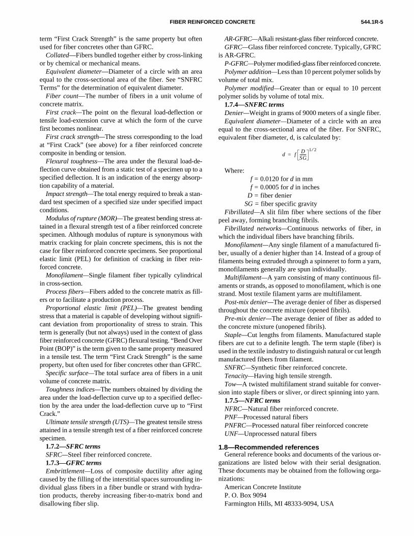
term “First Crack Strength” is the same property but ofused for fiber concretes other than GFRC.
Collated—Fibers bundled together either by cross-linkior by chemical or mechanical means.
Equivalent diameter—Diameter of a circle with an areequal to the cross-sectional area of the fiber. See “SNFTerms” for the determination of equivalent diameter.
Fiber count—The number of fibers in a unit volume oconcrete matrix.
First crack—The point on the flexural load-deflection otensile load-extension curve at which the form of the cufirst becomes nonlinear.
First crack strength—The stress corresponding to the loat “First Crack” (see above) for a fiber reinforced concrcomposite in bending or tension.
Flexural toughness—The area under the flexural load-dflection curve obtained from a static test of a specimen upspecified deflection. It is an indication of the energy absotion capability of a material.
Impact strength—The total energy required to break a stadard test specimen of a specified size under specified imconditions.
Modulus of rupture (MOR)—The greatest bending stress atained in a flexural strength test of a fiber reinforced concspecimen. Although modulus of rupture is synonymous wmatrix cracking for plain concrete specimens, this is notcase for fiber reinforced concrete specimens. See proportelastic limit (PEL) for definition of cracking in fiber reinforced concrete.
Monofilament—Single filament fiber typically cylindricalin cross-section.
Process fibers—Fibers added to the concrete matrix as fers or to facilitate a production process.
Proportional elastic limit (PEL)—The greatest bendingstress that a material is capable of developing without sigcant deviation from proportionality of stress to strain. Tterm is generally (but not always) used in the context of gfiber reinforced concrete (GFRC) flexural testing. “Bend OPoint (BOP)” is the term given to the same property measin a tensile test. The term “First Crack Strength” is the saproperty, but often used for fiber concretes other than GF
Specific surface—The total surface area of fibers in a uvolume of concrete matrix.
Toughness indices—The numbers obtained by dividing tharea under the load-deflection curve up to a specified detion by the area under the load-deflection curve up to “FCrack.”
Ultimate tensile strength (UTS)—The greatest tensile stresattained in a tensile strength test of a fiber reinforced concspecimen.
1.7.2—SFRC termsSFRC—Steel fiber reinforced concrete.1.7.3—GFRC termsEmbrittlement—Loss of composite ductility after agin
caused by the filling of the interstitial spaces surroundingdividual glass fibers in a fiber bundle or strand with hydtion products, thereby increasing fiber-to-matrix bond adisallowing fiber slip.
n
C
e
e
a-
-act
-tehe
nal
fi-sssrede
C.
c-st
te
--d
AR-GFRC—Alkali resistant-glass fiber reinforced concrete.GFRC—Glass fiber reinforced concrete. Typically, GFRC
is AR-GFRC.P-GFRC—Polymer modified-glass fiber reinforced concretePolymer addition—Less than 10 percent polymer solids by
volume of total mix.Polymer modified—Greater than or equal to 10 percen
polymer solids by volume of total mix.1.7.4—SNFRC termsDenier—Weight in grams of 9000 meters of a single fiberEquivalent diameter—Diameter of a circle with an area
equal to the cross-sectional area of the fiber. For SNFRequivalent fiber diameter, d, is calculated by:
Where:f = 0.0120 for d in mmf = 0.0005 for d in inches
D = fiber denierSG = fiber specific gravity
Fibrillated—A slit film fiber where sections of the fiberpeel away, forming branching fibrils.
Fibrillated networks—Continuous networks of fiber, inwhich the individual fibers have branching fibrils.
Monofilament—Any single filament of a manufactured fi-ber, usually of a denier higher than 14. Instead of a groupfilaments being extruded through a spinneret to form a yarmonofilaments generally are spun individually.
Multifilament—A yarn consisting of many continuous fil-aments or strands, as opposed to monofilament, which is ostrand. Most textile filament yarns are multifilament.
Post-mix denier—The average denier of fiber as dispersethroughout the concrete mixture (opened fibrils).
Pre-mix denier—The average denier of fiber as added tthe concrete mixture (unopened fibrils).
Staple—Cut lengths from filaments. Manufactured staplefibers are cut to a definite length. The term staple (fiber) used in the textile industry to distinguish natural or cut lengmanufactured fibers from filament.
SNFRC—Synthetic fiber reinforced concrete.Tenacity—Having high tensile strength.Tow—A twisted multifilament strand suitable for conver-
sion into staple fibers or sliver, or direct spinning into yarn1.7.5—NFRC termsNFRC—Natural fiber reinforced concrete.PNF—Processed natural fibersPNFRC—Processed natural fiber reinforced concreteUNF—Unprocessed natural fibers
1.8—Recommended referencesGeneral reference books and documents of the various
ganizations are listed below with their serial designatioThese documents may be obtained from the following orgnizations:
American Concrete InstituteP. O. Box 9094Farmington Hills, MI 48333-9094, USA
d fD
SG-------
1 2⁄=

0
o
m
d
n
o
n
e
c-tee
D
,
Iah9
rr
9
ic
7
snal
-.
re92,
.n,
of
-
d
st
i-
s-
-
y-
d
d
c
al
-
544.1R-6 MANUAL OF CONCRETE PRACTICE
American Society for Testing and Materials1916 Race Street, Philadelphia, PA 19103, USA
British Standards Institute2 Park Street, London W1A 2B5, England
Japanese Society of Civil EngineersMubanchi, Yotsuya 1 - chome, Shinjuku - ku, Tokyo 16Japan
RILEMPavillon Du Crous, 61 Av. Du President Wilson, 94235Cachan, France
1.8.1—ACI committee documents116 R Cement and Concrete Terminology201.2R Guide to Durable Concrete211.3 Standard Practice for Selecting Proportions for N
Slump Concrete223 Standard Practice for the Use of Shrinkage-Co
pensating Concrete304 R Guide for Measuring, Mixing, Transporting, an
Placing Concrete318 Building Code Requirements for Reinforced Co
crete506.1R State-of-the-Art Report on Fiber Reinforced Sh
crete506.2R Standard Specification for Materials, Proportio
ing, and Application of Shotcrete544.2R Measurement of Properties of Fiber Reinforc
Concrete544.3R Guide for Specifying, Proportioning, Mixing, Pla
ing, and Finishing Steel Fiber Reinforced Concre544.4R Design Considerations for Steel Fiber Reinforc
Concrete549R State-of-the-Art Report on Ferrocement
1.8.2ACI Special PublicationsSP-155 Testing of Fiber Reinforced Concrete, edited by
J. Stevens, N. Banthia, V. S. Gopalaratnam, andC. Tatnall, (Proceedings, March 1995 SymposiumSalt Lake City)
SP-142 Fiber Reinforced Concrete—Developments andnovations, edited by J. I. Daniel and S. P. Sh(Proceedings, March 1991 and November 19Symposia, Boston and Dallas)
SP-124 Thin-Section Fiber Reinforced Concrete and Fecement, edited by J. I. Daniel and S. P. Shah, (Pro-ceedings, February 1989 and November 198Symposia, Atlanta and San Diego)
SP-105 Fiber Reinforced Concrete Properties and Appltions, edited by S. P. Shah and G. B. Batson, (Pro-ceedings, November 1986 and March 198Symposia, Baltimore and San Antonio)
SP-81 Fiber Reinforced Concrete (Proceedings, Septem-ber 1982 Symposium, Detroit)
SP-44 Fiber Reinforced Concrete (Proceedings, October1973 Symposium, Ottawa)
,
-
-
-
t-
-
d
d
.P.
n-,
1
o-
a-
1.8.3—RILEM symposia volumes1. Proceedings 15,High Performance Fiber Reinforced Cement Composite,
edited by H. W. Reinhardt and A. E. Naaman, Proceedings of the InternatioWorkshop held jointly by RILEM and ACI, Stuttgart University and the University of Michigan, E & FN Spon, ISBN 0 419 39270 4, June 1991, 584 pp
2. Proceedings 17,Fibre Reinforced Cement and Concrete, edited by R. N.Swamy, Proceedings of the Fourth RILEM International Symposium on FibReinforced Cement and Concrete, E & FN Spon, ISBN 0 419 18130 X, 191376 pp.
3. Developments in Fibre Reinforced Cement and Concrete, RILEM Sym-posium Proceedings, RILEM Committee 49-TFR, 1986, 2 volumes.
4. Testing and Test Methods of Fibre Cement Composites, RILEM Sympo-sium Proceedings, Construction Press Ltd., 1978, 545 pp.
5. Fibre Reinforced Cement and Concrete, RILEM Symposium Proceed-ings, Construction Press Ltd., 1975, 650 pp. in 2 volumes.
1.8.4—Books1. Balaguru, P. N., and Shah, S. P.,Fiber-Reinforced Cement Composites,
McGraw-Hill, Inc., 1992.2. Daniel, J. I.; Roller, J. J;, Litvin, A.; Azizinamini, A.; and Anderson, E
D., “Fiber Reinforced Concrete,” SP 39.01T, Portland Cement AssociatioSkokie, 1991.
3. Majumdar, A. J., and Laws, V.,Glass Fibre Reinforced Cement, Build-ing Research Establishment (U.K.), BPS Professional Books Division Blackwell Scientific Publications Ltd., 1991, 192 pp.
4. Bentur, A., and Mindess, S.,Fibre Reinforced Cementitious Compos-ites, Elsevier Applied Science, 1990.
5. Swamy, R. N., and Barr, B.,Fibre Reinforced Cement and Concrete:Recent Developments, Elsevier Applied Science Publishers Ltd., 1989.
6. Steel Fiber Concrete, US-Sweden Joint Seminar, Elsevier Applied Science Publishers Ltd., 1986, 520 pp.
7. Hannant, D. J.,Fibre Cements and Fibre Concretes, John Wiley andSons, 1978.
1.8.5—ASTM standardsA 820 Specification for Steel Fibers for Fiber Reinforce
ConcreteC 31 Practice for Making and Curing Concrete Te
Specimens in the FieldC 39 Test Method for Compressive Strength of Cylindr
cal Concrete SpecimensC 78 Test Method for Flexural Strength of Concrete (U
ing Simple Beam with Third-Point Loading)C 94 Specification for Ready-Mixed ConcreteC 143 Test Method for Slump of Hydraulic Cement Con
creteC 157 Test Method for Length Change of Hardened H
draulic Cement Mortar and ConcreteC 172 Procedure for Sampling Freshly Mixed ConcreteC 173 Test Method for Air Content of Freshly Mixed
Concrete by the Volumetric MethodC 231 Test Method for Air Content of Freshly Mixed
Concrete by the Pressure MethodC 360 Test Method for Ball Penetration in Freshly Mixe
Hydraulic Cement ConcreteC 469 Test Method for Static Modulus of Elasticity an
Poisson’s Ratio of Concrete in CompressionC 597 Test Method for Pulse Velocity through ConcreteC 685 Specification for Concrete Made by Volumetri
Batching and Continuous MixingC 779 Test Method for Abrasion Resistance of Horizont
Concrete SurfacesC 827 Test Method for Early Volume Change of Cemen
titious Mixtures

c-m-
ern
d
irss-
nd
oll-
ndetn-
)onng
o
lsal
n-,
me
t in.
t,”
ter,
nt
nt,”nt
s in
,
I
s,”
Rec-Pre-
an-cedte,
hl,
troit,
tute,
e ofgatefailsent
nedsite
ent pre-con-s ofrtiesage,f theage, be-t ap-rackodel, ma-
wR.
re-lityon-y re-forod-
544.1R-7FIBER REINFORCED CONCRETE
C 947 Test Method for Flexural Properties of Thin-Setion Glass-Fiber Reinforced Concrete (Using Siple Beam with Third-Point Loading)
C 948 Test Method for Dry and Wet Bulk Density, WatAbsorption, and Apparent Porosity of Thin-SectioGlass-Fiber Reinforced Concrete
C 995 Test Method for Time of Flow of Fiber ReinforceConcrete Through Inverted Slump Cone
C 1018 Test Method for Flexural Toughness and FCrack Strength of Fiber Reinforced Concrete (Uing Beam with Third-Point Loading)
C 1116 Specification for Fiber Reinforced Concrete aShotcrete
C 1170 Test Methods for Consistency and Density of Rer-Compacted Concrete Using a Vibrating Table
C1228 Practice for Preparing Coupons for Flexural aWashout Tests on Glass-Fiber Reinforced Concr
C 1229 Test Method for Determination of Glass-Fiber Cotent in Glass-Fiber Reinforced Concrete (GFRC
C 1230 Test Method for Performing Tension Tests Glass-Fiber Reinforced Concrete (GFRC) BondiPads
E 84 Test Method for Surface Burning CharacteristicsBuilding Materials
E 119 Fire Tests of Building Construction and MateriaE 136 Test Method for Behavior of Materials in a Vertic
Tube Furnace at 750 C
1.8.6—British Standards InstituteBS 476: Part 4 Non-Combustibility Test for MaterialsBS 1881: Part 2 Methods of Testing Concrete
1.8.7—Japanese Society of Civil EngineersJSCE Standard III-1 Specification of Steel Fibers for Co
crete, Concrete Library No. 50, March1983
1.8.8—Indian standardsIS 5913: 1970 Acid Resistance Test for Materials
1.9—Cited references1.1 Shah, S. P., “Do Fibers Increase the Tensile Strength of Ce
Based Matrices?,”ACI Materials Journal, Vol. 88, No. 6, Nov. 1991, pp.595-602.
1.2 Naaman, A. E., “Fiber Reinforcement for Concrete,”Concrete Inter-national: Design and Construction, Vol. 7, No. 3, Mar. 1985, pp. 21-25.
1.3 Romualdi, J. P., and Batson, G. B., “Mechanics of Crack ArresConcrete,”J. Eng. Mech. Div., ASCE, Vol. 89, No. EM3, June 1963, pp147-168.
1.4 Biryukovich, K. L., and Yu, D. L., “Glass Fiber Reinforced Cementranslated by G. L. Cairns,CERA Translation, No. 12, Civil Eng. Res.Assoc., London, 1965, 41 pp.
1.5 Majumdar, A. J., “Properties of Fiber Cement Composites,”Pro-ceedings, RILEM Symp., London, 1975, Construction Press, Lancas1976, pp. 279-314.
1.6 Monfore, G. E., “A Review of Fiber Reinforced Portland CemePaste, Mortar, and Concrete,”J. Res. Dev. Labs, Portl. Cem. Assoc., Vol.10, No. 3, Sept. 1968, pp. 36-42.
1.7 Goldfein, S., “Plastic Fibrous Reinforcement for Portland CemeTechnical Report No. 1757-TR, U.S. Army Research and DevelopmeLaboratories, Fort Belvoir, Oct. 1963, pp. 1-16.
t
e
f
nt
1.8 Krenchel, H., and Shah, S., “Applications of Polypropylene FiberScandinavia,”Concrete International, Mar. 1985.
1.9 Naaman, A.; Shah. S.; and Throne, J.,Some Developments inPolypropylene Fibers for Concrete, SP-81, American Concrete InstituteDetroit, 1982, pp. 375-396.
1.10 ACI Committee 544, “Revision of State-of-the-Art Report (AC544 TR-73) on Fiber Reinforced Concrete,” ACI JOURNAL, Proceedings,Nov. 1973, Vol. 70, No. 11, pp. 727-744.
1.11 RILEM Technical Committee 19-FRC, “Fibre Concrete MaterialMaterials and Structures, Test Res., Vol. 10, No. 56, 1977, pp. 103-120.
1.12 PCI Committee on Glass Fiber Reinforced Concrete Panels, “ommended Practice for Glass Fiber Reinforced Concrete Panels,” cast/Prestressed Concrete Institute, Chicago, 1993.
1.13 PCI Committee on Glass Fiber Reinforced Concrete Panels, “Mual for Quality Control for Plants and Production of Glass Fiber ReinforConcrete Products,”MNL 130-91, Precast/Prestressed Concrete InstituChicago, 1991.
1.14 Steel Fiber Concrete, edited by S. P. Shah and A. SkarendaElsevier Applied Science Publishers, Ltd., 1986, 520 pp.
1.15 Fiber Reinforced Concrete Properties and Applications,edited byS. P. Shah and G. B. Batson, SP-105, American Concrete Institute, De1987, 597 pp.
1.16 Thin-Section Fiber Reinforced Concrete and Ferrocement, editedby J. I. Daniel and S. P. Shah, SP-124, American Concrete InstiDetroit, 1990, 441 pp.
1.17 Lankard, D. R., “Slurry Infiltrated Fiber Concrete (SIFCON),”Con-crete International, Vol. 6, No. 12, Dec. 1984, pp. 44-47.
CHAPTER 2—STEEL FIBER REINFORCEDCONCRETE (SFRC)
2.1—IntroductionSteel fiber reinforced concrete (SFRC) is concrete mad
hydraulic cements containing fine or fine and coarse aggreand discontinuous discrete steel fibers. In tension, SFRC only after the steel fiber breaks or is pulled out of the cemmatrix. shows a typical fractured surface of SFRC.
Properties of SFRC in both the freshly mixed and hardestate, including durability, are a consequence of its componature. The mechanics of how the fiber reinforcemstrengthens concrete or mortar, extending from the elasticcrack state to the partially plastic post-cracked state, is a tinuing research topic. One approach to the mechanicSFRC is to consider it a composite material whose propecan be related to the fiber properties (volume percentstrength, elastic modulus, and a fiber bonding parameter ofibers), the concrete properties (strength, volume percentand elastic modulus), and the properties of the interfacetween the fiber and the matrix. A more general and currenproach to the mechanics of fiber reinforcing assumes a carrest mechanism based on fracture mechanics. In this mthe energy to extend a crack and debond the fibers in thetrix relates to the properties of the composite.
Application design procedures for SFRC should follothe strength design methodology described in ACI 544.4
Good quality and economic construction with SFRC quires that approved mixing, placing, finishing, and quacontrol procedures be followed. Some training of the cstruction trades may be necessary to obtain satisfactorsults with SFRC. Generally, equipment currently used conventional concrete construction does not need to be mified for mixing, placing, and finishing SFRC.

544.1R-8 MANUAL OF CONCRETE PRACTICE
Table 2.1— Recommended combined aggregate gradations for steel fiber reinforcedconcrete
Percent Passing for Maximum Size of
U. S. standard sieve size3/8 in.
(10 mm)
1/2 in.(13 mm)
3/4 in.(19 mm)
1 in.(25 mm)
11/2 in.(38 mm)
2 (51 mm) 100 100 100 100 100
11/2 (38 mm) 100 100 100 100 85-100
1 (25 mm) 100 100 100 94-100 65-853/4 (19 mm) 100 100 94-100 76-82 58-771/2 (13 mm) 100 93-100 70-88 65-76 50-683/8 (10 mm) 96-100 85-96 61-73 56-66 46-58
#4 (5 mm) 72-84 58-78 48-56 45-53 38-50#8 (2.4 mm) 46-57 41-53 40-47 36-44 29-43#16 (1.1 mm) 34-44 32-42 32-40 29-38 21-34
#30 (600 m) 22-33 19-30 20-32 19-28 13-27
#50 (300 m) 10-18 8-15 10-20 8-20 7-19
#100 (150 m) 2-7 1-5 3-9 2-8 2-8
#200 (75 m) 0-2 0-2 0-2 0-2 0-2
µµµµ
Fig. 2.1—Fracture surface of SFRC
onle nep- ored
ed (ra
of be us-
leir
SFRC has advantages over conventional reinforced ccrete for several end uses in construction. One exampthe use of steel fiber reinforced shotcrete (SFRS) for tunlining, rock slope stabilization, and as lagging for the suport of excavation. Labor normally used in placing meshreinforcing bars in these applications may be eliminatOther applications are presented in this report.
2.1.1—Definition of fiber typesSteel fibers intended for reinforcing concrete are defin
as short, discrete lengths of steel having an aspect ratio
-isl
.
-
tio of length to diameter) from about 20 to 100, with any several cross-sections, and that are sufficiently small torandomly dispersed in an unhardened concrete mixtureing usual mixing procedures.
ASTM A 820 provides a classification for four generatypes of steel fibers based upon the product used in thmanufacture:
Type I—Cold-drawn wire. Type II—Cut sheet. Type III—Melt-extracted.

claion
bonituuir
oenl fi to int oersig.om inlatx-c).eeing
y bteeatecre
pro moesres
torsd in of
rse-o ofto
544.1R-9FIBER REINFORCED CONCRETE
Type IV—Other fibers.The Japanese Society of Civil Engineers (JSCE) has
sified steel fibers based on the shape of their cross-sect Type 1—Square section. Type 2—Circular section. Type 3—Crescent section.
The composition of steel fibers generally includes carsteel (or low carbon steel, sometimes with alloying constents), or stainless steel. Different applications may reqdifferent fiber compositions.
2.1.2—Manufacturing methods for steel fibersRound, straight steel fibers are produced by cutting
chopping wire, typically wire having a diameter betwe0.010 and 0.039 in. (0.25 to 1.00 mm). Flat, straight steebers having typical cross sections ranging from 0.0060.025 in. (0.15 to 0.64 mm) thickness by 0.010 to 0.080(0.25 to 2.03 mm) width are produced by shearing sheeflattening wire (Fig 2.2a). Crimped and deformed steel fibhave been produced with both full-length crimping (F2.2b), or bent or enlarged at the ends only (Fig. 2.2c,d). Sfibers have been deformed by bending or flattening tocrease mechanical bonding. Some fibers have been colinto bundles to facilitate handling and mixing. During miing, the bundles separate into individual fibers (Fig. 2.2Fibers are also produced from cold drawn wire that has bshaved down in order to make steel wool. The remainwires have a circular segment cross-section and macrimped to produce deformed fibers. Also available are sfibers made by a machining process that produces elongchips. These fibers have a rough, irregular surface and a cent-shaped cross section (Fig. 2.2e).
Steel fibers are also produced by the melt-extraction cess. This method uses a rotating wheel that contacts aten metal surface, lifts off liquid metal, and rapidly solidifiit into fibers. These fibers have an irregular surface, and ccent shaped cross-section (Fig. 2.2f).
fat
einr
adorted
w
edodedtio
dngC
re
s-:
-e
r
-
.r
e-ed
Fig. 2.2—Various steel fiber geometries
e
n
.4
lusl-ir
an- not fi-ureersail-o-ivesec-
ndces ra-Mon
2.1.3—HistoryResearch on closely-spaced wires and random metallic
bers in the late 1950s and early 1960s was the basis for a pon SFRC based on fiber spacing [2.1-2.3]. The Portland Cment Association (PCA) investigated fiber reinforcement the late 1950s [2.4]. Principles of composite materials weapplied to analyze fiber reinforced concrete [2.5, 2.6]. The dition of fibers was shown to increase toughness much mthan the first crack strength in these tests [2.6]. Another pabased on bond and the aspect ratio of the fibers was grante1972 [2.3]. Additional data on patents are documented in Ref-erence 2.7. Since the time of these original fibers, many nesteel fibers have been produced.
Applications of SFRC since the mid-1960s have includroad and floor slabs, refractory materials and concrete pructs. The first commercial SFRC pavement in the UnitStates was placed in August 1971 at a truck weighing stanear Ashland, Ohio [2.8].
The usefulness of SFRC has been aided by other newvelopments in the concrete field. High-range water-reduciadmixtures increase the workability of some harsh SFRmixtures [2.9] and have reduced supplier and contractor
n
elds-
-l-
-
i-ent-
-et
in
-
n
e-
-
sistance to the use of SFRC. Silica fume and accelerahave enabled steel fiber reinforced shotcrete to be placethicker layers. Silica fume also reduces the permeabilitythe shotcrete material [2.10].
2.2—Physical properties2.2.1—Fiber propertiesThe fiber strength, stiffness, and the ability of the fibe
to bond with the concrete are important fiber reinforcment properties. Bond is dependent on the aspect ratithe fiber. Typical aspect ratios range from about 20 100, while length dimensions range from 0.25 to 3 in. (6to 76 mm).
Steel fibers have a relatively high strength and moduof elasticity, they are protected from corrosion by the akaline environment of the cementitious matrix, and thebond to the matrix can be enhanced by mechanical chorage or surface roughness. Long term loading doesadversely influence the mechanical properties of steelbers. In particular environments such as high temperatrefractory applications, the use of stainless steel fibmay be required. Various grades of stainless steel, avable in fiber form, respond somewhat differently to expsure to elevated temperature and potentially corrosenvironments [2.11]. The user should consider all thefactors when designing with steel fiber reinforced refratory for specific applications.
ASTM A 820 establishes minimum tensile strength abending requirements for steel fibers as well as toleranfor length, diameter (or equivalent diameter), and aspecttio. The minimum tensile yield strength required by ASTA 820 is 50,000 psi (345 MPa), while the JSCE Specificatirequirement is 80,000 psi (552 MPa).

asfored
ofe a of theth-er vol-cyl-
ties,por-in
-sis-g
544.1R-10 MANUAL OF CONCRETE PRACTICE
Fig. 2.3—Relationship between slump, vebe time, andinverted cone time
flu votrix
uatida-ndtioope
asttionomnge-
pliith
itis C
theelampb-ve4].-fiove. Atioockte an ca
. to7-er
i- a
ecedvyro-
doglent
on- giv-llyrs
llgion,
rs, up
of by
ughon-amsrs.een
2.2.2—Properties of freshly-mixed SFRCThe properties of SFRC in its freshly mixed state are in
enced by the aspect ratio of the fiber, fiber geometry, itsume fraction, the matrix proportions, and the fiber-mainterfacial bond characteristics [2.12].
For conventionally placed SFRC applications, adeqworkability should be insured to allow placement, consoltion, and finishing with a minimum of effort, while providing uniform fiber distribution and minimum segregation ableeding. For a given mixture, the degree of consolidainfluences the strength and other hardened material prties, as it does for plain concrete.
In the typical ranges of volume fractions used for cin-place SFRC (0.25 to 1.5 volume percent), the addiof steel fibers may reduce the measured slump of the cposite as compared to a non-fibrous mixture in the raof 1 to 4 in. (25 to 102 mm). Since compaction by mchanical vibration is recommended in most SFRC apcations, assessing the workability of a SFRC mixture weither the Vebe consistometer, as described in the BrStandards Institution Standard BS 1881, or by ASTM995 Inverted Slump-Cone Time is recommended rathan the conventional slump measurement. A typical rtionship between slump, Vebe time, and Inverted SluCone time is shown in Fig. 2.3 [2.13]. Studies have estalished that a mixture with a relatively low slump can hagood consolidation properties under vibration [2.1Slump loss characteristics with time for SFRC and nonbrous concrete are similar [2.15]. In addition to the abconsiderations, the balling of fibers must be avoidedcollection of long thin steel fibers with an aspect ragreater than 100 will, if shaken together, tend to interlto form a mat, or ball, which is very difficult to separaby vibration alone. On the other hand, short fibers withaspect ratio less than 50 are not able to interlock and
-l-
e-
nr-
-
-e
-
h
r--
-
n
easily be dispersed by vibration [2.16]. However, shown in Section 2.2.3, a high aspect ratio is desired many improved mechanical properties in the hardenstate.
The tendency of a SFRC mixture to produce balling fibers in the freshly mixed state has been found to bfunction of the maximum size and the overall gradationthe aggregate used in the mixture, the aspect ratio offibers, the volume fraction, the fiber shape, and the meod of introducing the fibers into the mixture. The largthe maximum size aggregate and aspect ratio, the lessume fraction of fibers can be added without the tendento ball. Guidance for determining the fiber sizes and voumes to achieve adequate hardened composite properand how to balance these needs against the mix protions for satisfactory freshly mixed properties is given Section 2.3.
2.2.3—Properties of the hardened composite2.2.3.1Behavior under static loading—The mechanism
of fiber reinforcement of the cementitious matrix in concrete has been extensively studied in terms of the retance of the fibers to pullout from the matrix resultinfrom the breakdown of the fiber-matrix interfacial bondAttempts have been made to relate the bond strengththe composite mechanical properties of SFRC [2.12.27]. As a consequence of the gradual nature of fibpullout, fibers impart post-crack ductility to the cementtious matrix that would otherwise behave and fail inbrittle manner.
Improvements in ductility depend on the type and volumpercentage of fibers present [2.28-2.30]. Fibers with enhanresistance to pullout are fabricated with a crimped or waprofile, surface deformations, or improved end anchorage pvided by hooking, teeing or end enlargement (spade or bone shape). These types are more effective than equivastraight uniform fibers of the same length and diameter. Csequently, the amount of these fibers required to achieve aen level of improvement in strength and ductility is usualess than the amount of equivalent straight uniform fibe[2.31-2.33].
Steel fibers improve the ductility of concrete under amodes of loading, but their effectiveness in improvinstrength varies among compression, tension, shear, torsand flexure.
2.2.3.1.1 Compression—In compression, the ultimatestrength is only slightly affected by the presence of fibewith observed increases ranging from 0 to 15 percent forto 1.5 percent by volume of fibers [2.34-2.38].
2.2.3.1.2Direct tension—In direct tension, the improve-ment in strength is significant, with increases of the order30 to 40 percent reported for the addition of 1.5 percentvolume of fibers in mortar or concrete [2.38, 2.39].
2.2.3.1.3Shear and torsion—Steel fibers generally in-crease the shear and torsional strength of concrete, althothere are little data dealing strictly with the shear and torsial strength of SFRC, as opposed to that of reinforced bemade with a SFRC matrix and conventional reinforcing baThe increase in strength of SFRC in pure shear has b
coilureas
al tetee
au aderscincan thength) thl-ou
eo-th
gonamon
ar-adsa-
silety ofns
der
im-
on-.63- ford forim- in-boutt 3.5ob-pact
544.1R-11FIBER REINFORCED CONCRETE
shown to depend on the shear testing technique and thesequent degree of alignment of the fibers in the shear fazone [2.40]. For one percent by volume of fibers, the incres range from negligible to 30 percent [2.40].
Research has substantiated increased shear (diagonsion) capacity of SFRC and mortar beams [2.41-2.44]. Sfibers have several potential advantages when used toment or replace vertical stirrups in beams [2.45]. Thesevantages are: (1) the random distribution of fibthroughout the volume of concrete at much closer spathan is practical for the smallest reinforcing bars which lead to distributed cracking with reduced crack size; (2)first-crack tensile strength and the ultimate tensile streof the concrete may be increased by the fibers; and (3shear-friction strength is increased by resistance to puland by fibers bridging cracks.
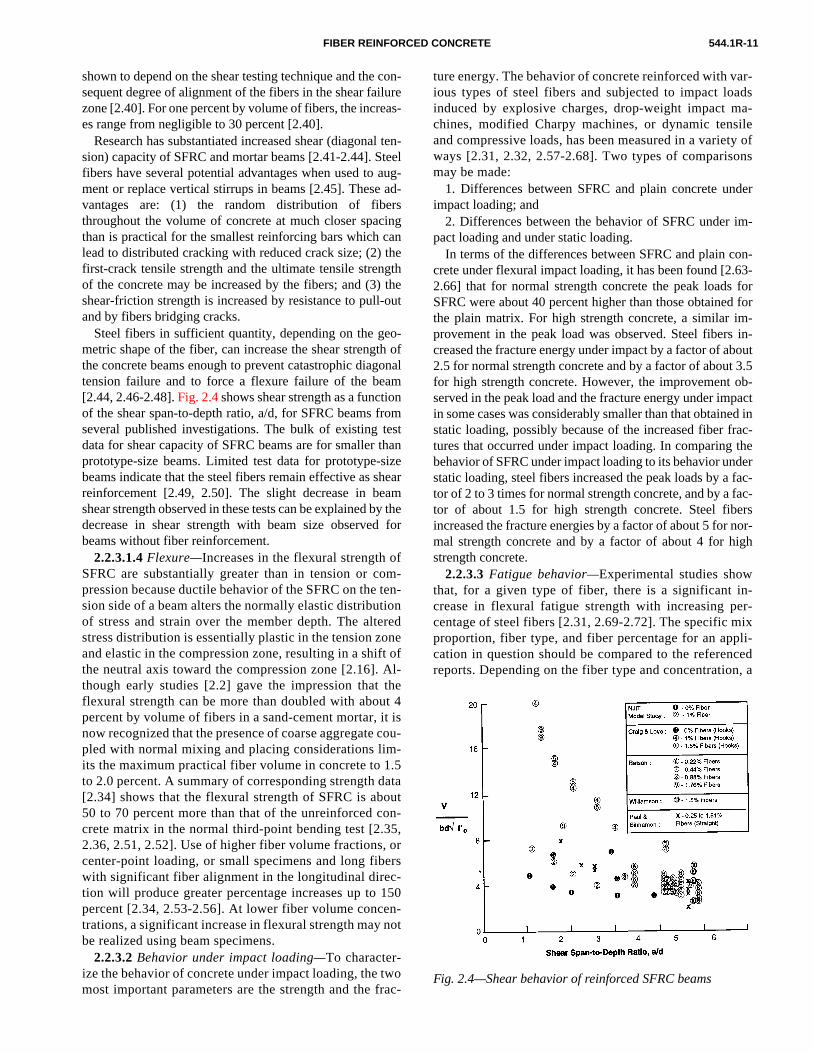
Steel fibers in sufficient quantity, depending on the gmetric shape of the fiber, can increase the shear strengthe concrete beams enough to prevent catastrophic diatension failure and to force a flexure failure of the be[2.44, 2.46-2.48]. Fig. 2.4 shows shear strength as a functi
fromtes thasizeheam
by d f
ofom tentionereoneft o Al-
ui
m1do
3,
c
n
tf
ed inrac- theder fac-fac-ers nor-igh
in-er-
ixpli-cedn, a
thet 4t is cou-
-.5ataut
on-5,
orers-150n-ot
woFig. 2.4—Shear behavior of reinforced SFRC beams
rac-of the shear span-to-depth ratio, a/d, for SFRC beams several published investigations. The bulk of existing data for shear capacity of SFRC beams are for smallerprototype-size beams. Limited test data for prototype-beams indicate that the steel fibers remain effective as sreinforcement [2.49, 2.50]. The slight decrease in beshear strength observed in these tests can be explained decrease in shear strength with beam size observebeams without fiber reinforcement.
2.2.3.1.4Flexure—Increases in the flexural strength SFRC are substantially greater than in tension or cpression because ductile behavior of the SFRC on thesion side of a beam alters the normally elastic distribuof stress and strain over the member depth. The altstress distribution is essentially plastic in the tension zand elastic in the compression zone, resulting in a shithe neutral axis toward the compression zone [2.16].though early studies [2.2] gave the impression that flexural strength can be more than doubled with abopercent by volume of fibers in a sand-cement mortar, now recognized that the presence of coarse aggregatepled with normal mixing and placing considerations liits the maximum practical fiber volume in concrete to to 2.0 percent. A summary of corresponding strength [2.34] shows that the flexural strength of SFRC is ab50 to 70 percent more than that of the unreinforced ccrete matrix in the normal third-point bending test [2.2.36, 2.51, 2.52]. Use of higher fiber volume fractionscenter-point loading, or small specimens and long fibwith significant fiber alignment in the longitudinal diretion will produce greater percentage increases up topercent [2.34, 2.53-2.56]. At lower fiber volume concetrations, a significant increase in flexural strength maybe realized using beam specimens.
2.2.3.2Behavior under impact loading—To character-ize the behavior of concrete under impact loading, themost important parameters are the strength and the
n-e-
n-lg--
g
et
ofal
tn
ar
theor
--
d
f
ture energy. The behavior of concrete reinforced with vious types of steel fibers and subjected to impact loinduced by explosive charges, drop-weight impact mchines, modified Charpy machines, or dynamic tenand compressive loads, has been measured in a varieways [2.31, 2.32, 2.57-2.68]. Two types of comparisomay be made:
1. Differences between SFRC and plain concrete unimpact loading; and
2. Differences between the behavior of SFRC under pact loading and under static loading.
In terms of the differences between SFRC and plain ccrete under flexural impact loading, it has been found [22.66] that for normal strength concrete the peak loadsSFRC were about 40 percent higher than those obtainethe plain matrix. For high strength concrete, a similar provement in the peak load was observed. Steel fiberscreased the fracture energy under impact by a factor of a2.5 for normal strength concrete and by a factor of aboufor high strength concrete. However, the improvement served in the peak load and the fracture energy under imin some cases was considerably smaller than that obtainstatic loading, possibly because of the increased fiber ftures that occurred under impact loading. In comparingbehavior of SFRC under impact loading to its behavior unstatic loading, steel fibers increased the peak loads by ator of 2 to 3 times for normal strength concrete, and by a tor of about 1.5 for high strength concrete. Steel fibincreased the fracture energies by a factor of about 5 formal strength concrete and by a factor of about 4 for hstrength concrete.
2.2.3.3Fatigue behavior—Experimental studies showthat, for a given type of fiber, there is a significant crease in flexural fatigue strength with increasing pcentage of steel fibers [2.31, 2.69-2.72]. The specific mproportion, fiber type, and fiber percentage for an apcation in question should be compared to the referenreports. Depending on the fiber type and concentratio

per-C
ous
,ost
fi- be
ec-re-sen,st,es its
ita-ofinggles
nceution
notta-ingesf
ofionndin-
544.1R-12
h-
MANUAL OF CONCRETE PRACTICE
Fig. 2.5—Schematic of load-deflection curves and tougness parameters
era ien
onaseetio.710hiad b
,les fr.
, safe sohe C
thesecks
topli-
lso,dingralalso isd on
-tofi-
properly designed SFRC mixture will have a fatigustrength of about 65 to 90 percent of the static flexustrength at 2 million cycles when nonreversed loadingused [2.72, 2.73], with slightly less fatigue strength whfull reversal of load is used [2.71].
It has been shown that the addition of fibers to conventially reinforced beams increases the fatigue life and decrethe crack width under fatigue loading [2.70]. It has also beshown that the fatigue strength of conventionally reinforcbeams made with SFRC increases. The resulting deflecchanges accompanying fatigue loading also decrease [2In some cases, residual static flexural strength has been 30 percent greater than for similar beams with no fatigue tory. One explanation for this increase is that the cyclic loing reduces initial residual tensile stresses causedshrinkage of the matrix [2.75].
2.2.3.4Creep and shrinkage—Limited test data [2.15, 2.762.77] indicate that steel wire fiber reinforcement at volumes than 1 percent have no significant effect on the creep andshrinkage behavior of portland cement mortar and concrete
ls
-esndn
4]. to
s--y
see
2.2.3.5 Modulus of elasticity and Poisson’s ratio—In prac-tice, when the volume percentage of fibers is less than 2 cent, the modulus of elasticity and Poisson’s ratio of SFRare generally taken as equal to those of a similar non-fibrconcrete or mortar.
2.2.3.6Toughness—Early in the development of SFRCtoughness was recognized as the characteristic that mclearly distinguishes SFRC from concrete without steel bers [2.78, 2.79]. Under impact conditions, toughness canqualitatively demonstrated by trying to break through a stion of SFRC with a hammer. For example, a steel fiber inforced mortar pot withstands multiple hammer blowbefore a hole is punched at the point of impact. Even ththe rest of the pot retains its structural integrity. In contraa similar pot made of mortar without steel fibers fracturinto several pieces after a single hammer blow, losingstructural integrity.
Under slow flexure conditions, toughness can be qualtively demonstrated by observing the flexural behavior simply supported beams [2.80]. A concrete beam containsteel fibers suffers damage by gradual development of sinor multiple cracks with increasing deflection, but retainsome degree of structural integrity and post-crack resistaeven with considerable deflection. A similar beam withosteel fibers fails suddenly at a small deflection by separatinto two pieces.
These two simple manifestations of toughness serve only to identify the characteristic of toughness in a qualitive sense, but also exemplify the two categories of testtechniques for quantifying toughness; namely, techniquinvolving either high-rate single or multiple applications oload, or a single slow-rate application of load.
The preferred technique for determining toughness SFRC is by flexural loading. This reflects the stress conditin the majority of applications such as paving, flooring, ashotcrete linings. Slow flexure is also preferable for determing toughness because the results are lower bound valuesfor use in design. Other fully instrumented tests are oftencomplex that the time and cost are prohibitive [2.80]. In tstandardized slow flexure methods, JSCE SF-4 and ASTM1018, a measure of toughness is derived from analysis ofload-deflection curve as indicated in Fig. 2.5. Details of themethods along with a discussion of their merits and drawbaare presented in References 2.80, 2.81, and 2.82. These testmethods provide specifiers and designers with a methodspecify and test for toughness levels appropriate to their apcations. As an example, for SFRC tunnel linings, I5 and I10toughness indices sometimes have been specified. Atoughness indices and residual strength factors corresponto higher end-point deflections as well as minimum flexustrength requirements as described in ASTM C 1018 are being used. The JSCE SF-4 equivalent flexural strengthsometimes used as an alternate to design methods basefirst-crack strength for slab-on-grade design.
2.2.3.7Thermal conductivity—Small increases in the thermal conductivity of steel fiber reinforced mortar with 0.5 1.5 percent by volume of fiber were found with increasing ber content [2.83].

ned -see tas ic tesles
ainom
wec-cetedeinllin fro
Forritepoan Ai ar].
-dael
onsbeuragm)s tith
tin-ounts of
p-fi-ucineb
ver
entretrac04
oss04
cal-nt.adions.
medly invior
fresh en-ein-
iallye ex-h the
sur-tain- arelva-d in
nvi- fac-turehen thefrom mayon
ne ofkage
ly
den-s inur,rosssileressal-
to re-ry tos ofris-med the theone-n isses out are
niax-
544.1R-13FIBER REINFORCED CONCRETE
2.2.3.8Abrasion resistance—Steel fibers have no effect oabrasion resistance of concrete by particulate debris carrislowly flowing water. However, under high velocity flow producing cavitation conditions and large impact forces cauby the debris, SFRC has significantly improved resistancdisintegration [2.31, 2.57, 2.83-2.86]. Abrasion resistance relates to pavement and slab wear under wheeled trafflargely unaffected by steel fibers. Standard abrasion (ASTM C 779-Procedure C) on field and laboratory sampconfirm this observation [2.87].
2.2.3.9 Friction and skid resistance—Static friction,skid, and rolling resistance of SFRC and identical plconcrete cast into laboratory-size slab samples were cpared in a simulated skid test [2.88]. The SFRC had3/8 in.(9.5 mm) maximum size aggregates. Test results shothat the coefficient of static friction for dry concrete surfaes, with no wear, erosion, or deterioration of the surfawas independent of the steel fiber content. After simulaabrasion and erosion of the surface, the steel fiber rforced surfaces had up to 15 percent higher skid and roresistance than did plain concrete under dry, wet, andzen surface conditions.
2.2.4—Durability2.2.4.1Freezing and thawing—All the well-known prac-
tices for making durable concrete apply to SFRC. freezing and thawing resistance, the same air content cria should be used as is recommended in ACI 201. Exsure tests have generally revealed that for freezing thawing resistance, SFRC must be air-entrained [2.89].void characteristics of SFRC and non-fibrous concretesimilar in nature, supporting the above hypothesis [2.15
2.2.4.2Corrosion of fibers: crack-free concrete—Expe-rience to date has shown that if a concrete has a 28compressive strength over 3000 psi (21 MPa), is wcompacted, and complies with ACI 318 recommendatifor water-cement ratio, then corrosion of fibers will limited to the surface skin of the concrete. Once the sface fibers corrode, there does not seem to be a proption of the corrosion much more than 0.10 in. (2.5 mbelow the surface. This limited surface corrosion seemexist even when the concrete is highly saturated wchloride ions [2.90]. Since the fibers are short, disconuous, and rarely touch each other, there is no continuconductive path for stray or induced currents or currefrom electromotive potential between different areasthe concrete.
Limited experience is available on fiber corrosion in aplications subjected to thermal cycling. Short length bers do not debond under thermal cycling, although sdebonding can occur with conventional bar or mesh reforcement. Since the corrosion mechanism occurs in donded areas, SFRC has improved durability oconventional reinforced concrete for this application.
2.2.4.3 Corrosion of fibers: cracked concrete—Labora-tory and field testing of cracked SFRC in an environmcontaining chlorides has indicated that cracks in conccan lead to corrosion of the fibers passing across the c[2.91]. However, crack widths of less than 0.1 mm (0.0
in
doitists
-
d
,
-g-
--dre
yl
-a-
o
s
h--
ek
in.) do not allow corrosion of steel fibers passing acrthe crack [2.92]. If the cracks wider than 0.1 mm (0.0in.) are limited in depth, the consequences of this loized corrosion may not always be structurally significaHowever, if flexural or tensile cracking of SFRC can leto a catastrophic structural condition, full consideratshould be given to the possibility of corrosion at crack
Most of the corrosion testing of SFRC has been perforin a saturated chloride environment, either experimentalthe laboratory or in a marine tidal zone. Corrosion behaof SFRC in aggressive non-saturated environment or in water exposure is limited. Based on the tests in chloridevironments and the present knowledge of corrosion of rforcement, it is prudent to consider that in most potentaggressive environments where cracks in SFRC can bpected, corrosion of carbon steel fibers passing througcrack will occur to some extent.
To reduce the potential for corrosion at cracks or face staining, the use of alloyed carbon steel fibers, sless steel fibers, or galvanized carbon steel fiberspossible alternatives. Precautions for the use of ganized steels in concrete must be observed as outlineACI 549.
2.2.5—Shrinkage crackingConcrete shrinks when it is subjected to a drying e
ronment. The extent of shrinkage depends on manytors including the properties of the materials, temperaand relative humidity of the environment, the age wconcrete is subjected to the drying environment, andsize of the concrete mass. If concrete is restrained shrinkage, then tensile stresses develop and concretecrack. Shrinkage cracking is one of the more commcauses of cracking for walls, slabs, and pavements. Othe methods to reduce the adverse effects of shrincracking is reinforcing the concrete with short, randomdistributed, steel fibers.
Since concrete is almost always restrained, the tency for cracking is common. Steel fibers have three rolesuch situations: (1) they allow multiple cracking to occ(2) they allow tensile stresses to be transferred accracks, i.e., the composite maintains residual tenstrength even if shrinkage cracks occur, and (3) sttransfer can occur for a long time, permitting heing/sealing of the cracks [2.91].
There is no standard test to assess cracking due strained shrinkage. A suitable test method is necessaevaluate the efficiency of different types and amountfibers. ASTM C 157 recommends the use of a long, pmatic specimen to measure free shrinkage. If it is assuthat the length of the specimen is much larger thancross-sectional dimensions, then the observation ofchange in length with time can provide a measure of dimensional shrinkage. If this long-prismatic specimerestrained from shrinking, then uniaxial tensile stresare produced. If a restrained shrinkage test is carriedsuch that essentially uniform, uniaxial tensile stressesproduced, then such a test is somewhat similar to a uial tensile test.

544.1R-14 MANUAL OF CONCRETE PRACTICE
Table 2.2— Range of proportions for normal weight steel fiber reinforced concrete
Mix parameters
3/8 in. maximum-sizeaggregate
3/4 in. maximum-sizeaggregate
11/2 in. maximum-sizeaggregate
Cement, lb/yd3 600-1000 500-900 470-700w/c Ratio 0.35-0.45 0.35-0.50 0.35-0.55Percent of fine to coarseaggregate 45-60 45-55 40-55
Entrained air content, percent 4-8 4-6 4-5Fiber content, vol. percent Deformed fiber Smooth fiber
0.4-1.00.8-2.0
0.3-0.80.6-1.6
0.2-0.70.4-1.4
eci-
otn ineragensof
ix-herin-n-
Cree
An alternate simple approach is to use ring-type spmens as discussed in References 2.76, 2.77, and 2.93through 2.96. While the addition of steel fibers may nreduce the total amount of restrained shrinkage, it cacrease the number of cracks and thus reduce the avcrack widths. Some results for SFRC ring-type specimare shown in Fig. 2.6. It can be seen that the addition
ht,m-
ver
th- re- to the
- theersan
irst ing,
ed
nal
n-e-
inglic
edsate
l-e
se-o-hec-erel
Fig. 2.6—Average crack width versus fiber volume
even a small amount (0.25 vol. percent) of straigsmooth steel fibers 1 inch long and 0.016 inches in diaeter (25 mm by 0.4 mm in diameter) can reduce the aage crack width significantly (1/5 the value of the plainconcrete specimen).
2.3—Preparation technologiesMixing of SRFC can be accomplished by several me
ods, with the choice of method depending on the jobquirements and the facilities available. It is importanthave a uniform dispersion of the fibers and to preventsegregation or balling of the fibers during mixing.
Balling of the fibers during mixing is related to a number of factors. The most important factors appear to beaspect ratio of the fibers, the volume percentage of fibthe maximum size and gradation of the aggregates, the method of adding the fibers to the mixture. As the fthree of these factors increase, the tendency for ballingcreases. Refer to ACI 544.3R, “Guide For SpecifyinMixing, Placing, and Finishing Steel Fiber ReinforcConcrete” for additional information.
2.3.1—Mix proportions
-e
-
,d
-
Compared to conventional concrete, some SFRC mtures are characterized by higher cement content, higfine aggregate content, and decreasing slump with creasing fiber content. Since consolidation with mechaical vibration is recommended in most SFRapplications, assessing the workability of a SFRC mixtuwith ASTM C 995 Inverted Slump-Cone Time or thVebe test is recommended rather than the conventioslump measurement.
Conventional admixtures and pozzolans are commoly used in SFRC mixtures for air entrainment, water rduction, workability, and shrinkage control. A mixproportioning procedure that has been used for pavand structural applications and in the repair of hydraustructures is described in References 2.84 and 2.97. Testresults indicate that lightweight SFRC can be formulatwith minor modifications [2.98]. Also, experience hashown that if the combined fine and coarse aggreggradation envelopes as shown in Table 2.1 are met, thetendency to form fiber balls is minimized and workabiity is enhanced [2.99, 2.100]. Alternatively, a mixturbased on experience, such as those shown in Table 2.2,can be used for a trial mix. Once a mixture has beenlected, it is highly advisable that a full field batch be prcessed prior to actual start of construction with tmixing equipment that will be used for the project. Reommendations for trial mixes and the maximum fibcontent for good workability are available from the stefiber manufacturers.
Fig. 2.7—Adding steel fibers to a loaded mixer truck viaconveyor

544.1R-15FIBER REINFORCED CONCRETE
o or
Fig. 2.8—Adding steel fibers via conveyor onto charging cveyor in a batch plantlythea
e-
p-
lddedn
en
e
hteete
arre
be
reteers.e, aeral,e orrele-isms
fail-sile
ten- fol-to(orusedof the
xnt
dsima-
der-gy
c-
b-
2.3.2 —Mixing methodsIt is very important that the fibers be dispersed uniform
throughout the mixture. This must be done during batching and mixing phase. Several mixing sequences hbeen successfully used, including the following:
1. Add the fibers to the truck mixer after all other ingrdients, including the water, have been added andmixed. Steel fibers should be added to the mixer hoper at the rate of about 100 lbs (45 kg) per minute,with the mixer rotating at full speed. The fibers shoube added in a clump-free state so that the mixer blacan carry the fibers into the mixer. The mixer shoulthen be slowed to the recommended mixing speed amixed for 40 to 50 revolutions. Steel fibers have beadded manually by emptying the containers into thetruck hopper, or via a conveyor belt or blower asshown in. Using this method, steel fibers can be addat the batch plant or on the job site.
2. Add the fibers to the aggregate stream in the batcplant before the aggregate is added to the mixer. Sfibers can be added manually on top of the aggregaon the charging conveyor belt, or via another con-veyor emptying onto the charging belt as shown inFig. 2.8. The fibers should be spread out along theconveyor belt to prevent clumping.
3. Add the fibers on top of the aggregates after they weighed in the batcher. The normal flow of the agggates out of the weigh batcher will distribute thefibers throughout the aggregates. Steel fibers can added manually or via a conveyor as shown in Fig.2.9.
ldbtieon
n- Fig. 2.9—Adding steel fibers to weigh batcher via conveybelt
i-
ealdd
sc-a-
-
SFRC delivered to projects should conform to the appcable provisions of ASTM C 1116. For currently usemanual steel fiber charging methods, workers should equipped with protective gloves and goggles. It is essenthat tightly bound fiber clumps be broken up or preventfrom entering the mix. It is recommended that the methof introducing the steel fibers into the mixture be provein the field during a trial mix.
ve
s
d
d
ls
e-
2.4—Theoretical modelingIt is well recognized that the tensile behavior of conc
matrices can be improved by the incorporation of fibDepending upon the fiber geometry and the fiber typnumber of failure mechanisms can be achieved. In genanalytical models are formulated on the basis of onmore of these mechanisms of failure. It is therefore vant to describe the primary types of failure mechanin fiber reinforced concrete composites.
Similar to the behavior of plain concrete, composite ure under most types of loading is initiated by the tencracking of the matrix along planes where the normalsile strains exceed the ultimate values. This may belowed by multiple cracking of the matrix prior composite fracture, if the fibers are sufficiently long continuous). However, when short strong fibers are (steel, glass, etc.), once the matrix has cracked, one following types of failure will occur:
1. The composite fractures immediately after matricracking. This results from inadequate fiber conteat the critical section or insufficient fiber lengths totransfer stresses across the matrix crack.
2. The composite continues to carry decreasing loaafter the peak. The post-cracking resistance is prrily attributed to fiber pull-out. While no significantincrease in composite strength is observed, consiable enhancement of the composite fracture enerand toughness is obtained, as is shown in Fig. 2.10.
This toughness allows cracks in indeterminate strutures to work as hinges and to redistribute loads. Inthis way, the failure load of the structure may be sustantially higher than for the unreinforced structurealthough the flexural strength of the plain concrete,tested on beams, is not increased.3. The composite continues to carry increasing loadafter matrix cracking. The peak load-carrying capaity of the composite and the corresponding deformtion are significantly greater than that of theunreinforced matrix. During the pre-peak inelasticregime of the composite response, progressive deb

544.1R-16
tests
MANUAL OF CONCRETE PRACTICE
Fig. 2.10—Typical results of stress-displacement curves obtained from direct tensionon plain mortar matrix and SFRC
n-res
for assitelselble
aod
ome
frack fi- faonetmer-ite
r thichMforncsin fock
od-in-ofom-w-te;ofe ap-ainge
clu-de-
c-gn-ip
k-enck-e-]. the-renu-veeake-in- int theeb-
-e
onding and softening of the interface may be resposible for the energy absorption processes. It is cleathat this mode of composite failure is essentially thsame as for type 2, but provides higher failure loadand controlled crack growth.
Based in part on the fundamental approach in their mulation, analytical models can be categorized [2.101]models based on the theory of multiple fracture, compomodels, strain-relief models, fracture mechanics modinterface mechanics models, and micromechanics modFairly exhaustive reviews of these models are availaelsewhere [2.101, 2.102]. Brief reviews of the fracture mchanics models and the interface mechanics modelsgiven here, as these are typically the most suitable for meling the inelastic processes in short-fiber composites.
Two broad categories of models can be identified frthe fracture mechanics-based models. The more fundamtal class of models uses the concepts of linear elastic ture mechanics (LEFM) to solve the problem of crainitiation, growth, arrest, and stability in the presence ofbers through appropriate changes in the stress intensitytor [2.1, 2.2]. Typically these models assume perfect bbetween the fiber and the matrix, and are one-paramfracture models. Unlike the classical LEFM models, soof the later models implicitly account for the inelastic inteface response during crack growth in such composthrough a nonlinear stress-displacement relationship fofiber-bridging zone (process zone). This approach, whhas come to be known as the fictitious crack model (FC[2.102], is conceptually similar to that described earlier the fracture of unreinforced concrete. The major differees in the fictitious crack models [2.103, 2.106] are the gularity assumptions at the crack-tip, the criteria usedcrack initiation and growth, and the stability of the cragrowth.
-:
e,s.e-re-
n-c-
c-der
se
)
--r
Others [2.107] have proposed a fracture mechanics mel to predict the crack propagation resistance of fiber reforced concrete that is somewhat different from either these two approaches. Fracture resistance in fibrous cposites according to this model is separated into the folloing four regimes: linear elastic behavior of the composisubcritical crack growth in the matrix and the beginning the fiber bridging effect; post-critical crack growth in thmatrix such that the net stress intensity factor due to theplied load and the fiber bridging closing stresses remconstant (steady state crack growth); and the final stawhere the resistance to crack separation is provided exsively by the fibers. The model uses two parameters to scribe the matrix fracture properties (KS1C, modifiedcritical stress intensity factor based on LEFM and the effetive crack length, and CTOD, the critical crack tip openindisplacement, as described earlier for unreinforced cocrete), and a fiber pull-out stress-crack-width relationshas the basic input information.
All of the fictitious crack models rely on the stress-cracwidth relations obtained experimentally. There have besome attempts at predicting the macroscopic stress-crawidth relations of the composite from a study of the mchanics of the fiber-matrix interface [2.24, 2.108-2.113They can be grouped as models based on the shear-lagory or modifications thereof [2.108-2.110, 2.113], fractumechanics based interface models [2.24, 2.113], and merical models [2.24, 2.112] Many of these models habeen successful to varying degrees in predicting the ppull-out loads [2.24, 2.108-2.113] and the load-slip rsponse [2.110, 2.112, 2.113-2.115] of idealized aligned sgle fiber pull-out. These models have been very usefulunderstanding the basic mechanics of stress transfer ainterface and showing that the interface softening and donding play an important role in the fracture of such composites. However, significant research efforts will b

hatednta
wit a in
tialowdi
beionocn
4Ronsilnatesign th intotckcitthel aing wi in
fi-neonrio oh focuofar
behapt
sily oveveesn be, idein
deal
ideed
aveeseark-7
rersthe
ef-in re-ac-teel
n-sed
ain- areon-
in-ing.
itytat-rac-hiserop-te.fol-
s-ialg
21],reu-d-en
e-C
gs.in-retest
one-me
ft-
544.1R-17FIBER REINFORCED CONCRETE
needed to modify these models to predict the pull-out cacteristics of the inclined fibers that are randomly orienat a matrix crack (randomness in both the angular orietion as well as the embedment length).
2.5—Design considerationsThe designer may best view SFRC as a concrete
increased strain capacity, impact resistance, energysorption, fatigue endurance, and tensile strength. Thecrease in these properties will vary from nil to substandepending on the quantity and type of fibers used. Hever, composite properties will not usually increase rectly with the volume of fibers added.
Several approaches to the design and sizing of memwith SFRC are available. These are based on conventdesign methods generally supplemented by special prdures for the fiber contribution. Additional informatioon design considerations may be found in ACI 544.“Design Considerations for Steel Fiber Reinforced Ccrete.” These methods generally account for the tencontribution of the SFRC when considering the interforces in the member. When supported by full scale data, these approaches can provide satisfactory desThe major differences in the proposed methods is indetermination of the magnitude of the tensile stresscrease due to the fibers and the manner in which the force is calculated. Another approach is to consider craas plastic hinges in which the remaining moment capadepends on the type and quantity of fibers present. Oapproaches that have been used are often empiricamay apply only in certain cases where limited supporttest data have been obtained. They should be usedcaution in new applications, and only after adequatevestigation.
Generally, for flexural structural components, steelbers should be used in conjunction with properly desigcontinuous reinforcement. Steel fibers can reliably cfine cracking and improve resistance to material deteration as a result of fatigue, impact, and shrinkagethermal loads. A conservative but reasonable approacstructural members where flexural or tensile loads ocsuch as in beams, columns, or elevated slabs (rofloors, or other slabs not on grade) is that reinforcing bmust be used to resist the total tensile load. This iscause the variability of fiber distribution may be such tlow fiber content in critical areas could lead to unacceable reduction in strength.
In applications where the presence of continuous tenreinforcement is not essential to the safety and integritthe structure, such as floors on grade, pavements, olays, ground support, and shotcrete linings, the improments in flexural strength, impact resistance, toughnand fatigue performance associated with the fibers caused to reduce section thickness, improve performancboth. For structural concrete, ACI 318 does not provfor use of the additional tensile strength of the fiber reforced concrete in building design, and therefore thesign of reinforcement must still follow the usu
r-
-
hb--
,--
rsale-
,-elts.
e-alsyr
nd
th-
d--rr
rs,s-
t-
efr--s,e
or
--
procedure. Other applications, as noted above, provmore freedom to take full advantage of the improvproperties of SFRC.
There are some applications where steel fibers hbeen used without reinforcing bars to carry loads. Thhave been short span, elevated slabs, for example, a ping garage at Heathrow Airport with slabs 3 ft-6 in. (1.0m) square by 21/2 in. (10 cm) thick, supported on fousides [2.116]. In such cases, the reliability of the membshould be demonstrated by full-scale load tests and fabrication should employ rigid quality control.
Some full-scale tests have shown that steel fibers arefective in supplementing or replacing the stirrups beams [2.44, 2.45, 2.117], although supplementing orplacing stirrups with steel fibers is not an accepted prtice at present. These full-scale tests have shown that sfibers in combination with reinforcing bars can also icrease the moment capacity of reinforced and prestresconcrete beams [2.44, 2.118, 2.119].
Steel fibers can also provide an adequate internal restring mechanism when shrinkage-compensating cementsused so that the concrete system will perform its crack ctrol function even when restraint from conventional reforcement is not provided [2.120]. Guidance concernshrinkage-compensating concrete is available in ACI 223
2.6—ApplicationsThe applications of SFRC will depend on the ingenu
of the designer and builder in taking advantage of the sic and dynamic tensile strength, energy absorbing chateristics, toughness, and fatigue endurance of tcomposite material. The uniform dispersion of fibthroughout the concrete provides isotropic strength prerties not common to conventionally reinforced concre
Present applications of SFRC are discussed in the lowing sections.
2.6.1—Applications of cast-in-place SFRCMany cast-in-place SFRC applications involve slab
on-grade, either in the form of pavements or industrfloors. As early as 1983, twenty-two airport pavinprojects had been completed in the United States [2.1and over 20 million square feet (1.9 million squameters) of industrial flooring had been constructed in Erope through 1990 [2.122]. Many other projects, incluing bridge deck overlays and floor overlays, have bereported [2.8, 2.123].
In 1971, the U.S. Army Construction Engineering Rsearch Laboratory performed controlled testing of SFRrunway slabs subjected to C5A airplane wheel loadinBased on this investigation, the Federal Aviation Admistration prepared a design guide for steel fibrous concfor airport pavement applications [2.124]. Analysis of tedata indicated that SFRC slabs need to be only about half the thickness of plain concrete slabs for the sawheel loads.
An example of SFRC industrial floors is the 796,000 2
(74,000 m2) Honda Automobile Assembly and Office Build

544.1R-18
in r
MANUAL OF CONCRETE PRACTICE
Fig. 2.11—Typical effects of fiber type on the stress-stracurve of SIFCON in compression
ft.in.33-
sisusng0cedece
coenol.
rsC
m
in
than d
a
a-
on
one i
g
Al-
im-ugh-lacetic
00ton
ernre- the
fere-ick-irdsaryent.ugh-
allied inpres-ing
en-7.3
stes.
d inn,
theults
ing in Alliston, Ontario, Canada, of which 581,000 sq.(54,000 m2) is slab-on-grade. This slab-on-grade is 6 (150 mm) thick and reinforced with 0.25 vol. percent or lbs/yd3 (20 kgs/m3) of 2.4 inch long (60 mm) deformed fibers.
Other cast-in-place applications include an impact retant encasement of a turbine test facility for WestinghoElectric Corp., Philadelphia, PA [2.126]. SFRC containi120 lbs/yd3 (71 kgs/m3) of 2.0 in. by 0.020 in. diameter (5mm by 0.50 mm diameter) crimped-end fibers was plaby pumping. Although the concrete encasement incluconventional reinforcement, the use of steel fibers reduthe required thickness by one-third.
In 1984, 500,000 ft2 (46,000 m2) of 4-in. thick (100 mm)SFRC was placed as a replacement of the upstream crete facing placed in 1909 at the Barr Lake Dam near Dver, CO [2.127]. The SFRC mixture contained 0.6 vpercent or 80 lbs/yd3 (47 kgs/m3) of 2.4 in. by 0.039 in. di-ameter (60 mm by 0.80 mm diameter) crimped-end fibeand 11/2 in. (38 mm) maximum-size aggregate. The SFRwas pumped to a slip-form screed to pave the 47 ft (14high, 2.5 to 1 slope facing.
Several other applications of cast-in-place SFRC clude:
1. Repairs and new construction on major dams and ohydraulic structures to provide resistance to cavitation severe erosion caused by the impact of large waterbornebris [2.99].
2. Repairs and rehabilitation of marine structures suchconcrete piling and caissons [2.88].
3. Bonded overlays in industrial floor and highway rehbilitation [2.128].
4. Slip-formed, cast-in-place tunnel lining [2.129].5. Latex-modified SFRC bridge deck overlays in Oreg
[2.130].6. Highway paving [2.131].7. Large, 77,000 ft2 (7,150 m2) industrial floor-on-grade
[2.132].8. Roller-compacted concrete (RCC) for pavement c
struction. Recent work has shown that steel fibers can b
Fig. 2.12—Tensile stress-strain response of hooked fibeSIFCON composites
-e
ddd
n--
,
)
-
erde-
s
-n-
corporated into RCC paving mixes with resultinimprovements in material properties [2.133].
9. Bonded overlay repairs to over 50 bridge decks in berta, Canada [2.134].
2.6.2—Applications of precast SFRCMany precast applications for SFRC make use of the
provement in properties such as impact resistance or toness. Other precast applications use steel fibers to repconventional reinforcement in utility boxes and septanks.
Some recent applications are cited:Dolosse: In 1982 and 1985 30,000 cubic yards (22,9
cubic meters) of SFRC were placed in over 1,500 42 (38 MT) dolosse by the Corps of Engineers in NorthCalifornia. SFRC was specified in lieu of conventional inforcing bars to improve the wave impact resistance ofdolosse [2.135].
Vaults and Safes: Since 1984, most of the vault and samanufacturers in North America have used SFRC in pcast panels that are then used to construct vaults. Thnesses of vault walls have been reduced by up to two-thover the cast-in-place method. Steel fiber contents vfrom less than 1 volume percent to over 3 volume percSFRC is used to increase the impact resistance and toness of the panels against penetration.
Mine Crib Blocks: These units, made with conventionconcrete masonry machines, are routinely suppthroughout the U.S. for building roof support structurescoal mines. Steel fibers are used to increase the comsive toughness of the concrete to allow controlled crushand thus prevent catastrophic failures [2.136].
Tilt-up Panels: SFRC has been used to replace convtional reinforcement in tilt-up panels up to 24 feet high (m) [2.137].
Precast Garages: SFRC is used in Europe to precacomplete automobile garages for single family residenc
2.6.3—ShotcreteSteel fiber reinforced shotcrete (SFRS) was first use
ground support applications. Its first practical applicatioa trial use for rock slope stabilization in 1974 along Snake River, Washington, showed very good res

vehy-ol-
ced40a-
hinuc-ndteingbutheoil deilarlus
ofreu-rk
al-or
inme
al- anching
pes-reeties
var ksned ad
rve-de50sse
sile57 foflec000
a)
een
ten-
gthe ap-, re-nd
nt inin-for-asro-edrs,s.oryack-ndto-g in areether
ail-orkracktorych-nt of
re re-ser-of
and
: Inlly
ap- re-e itpal- re-r insta-
r lin-ac- the
be-gen-rs.ay
544.1R-19FIBER REINFORCED CONCRETE
[2.138, 2.139]. Since that time, many applications habeen made in slope stabilization, in ground support for droelectric, transportation and mining tunnels, and in sdier pile retaining walls as concrete lagging that is plaas the structure is constructed from the top down [2.12.142]. Additional references and more complete informtion on SFRS may be found in ACI 506.1R.
Besides ground support, SFRS applications include tshell hemispherical domes cast on inflation-formed strtures [2.143]; artificial rockscapes using both dry-mix awet-mix steel fiber reinforced silica fume shotcre[2.144]; houses in England [2.145]; repair and reinforcof structures such as lighthouses, bridge piers, and aments [2.146]; channel lining and slope stabilization on Mt. St. Helens Sediment Control Structure; lining of storage caverns in Sweden; resurfacing of rocket flameflectors at Cape Kennedy, and forming of boat hulls simto ferrocement using steel fibers alone and fibers pmesh.
2.6.4 —SIFCON (Slurry Infiltrated Fiber Concrete)Slurry Infiltrated Fiber Concrete (SIFCON) is a type
fiber reinforced concrete in which formwork molds afilled to capacity with randomly-oriented steel fibers, usally in the loose condition, and the resulting fiber netwois infiltrated by a cement-based slurry. Infiltration is usuly accomplished by gravity flow aided by light vibration, by pressure grouting.
SIFCON composites differ from conventional SFRCat least two respects: they contain a much larger volufraction of fibers (usually 8 to 12 volume percent, but vues of up to 25 volume percent have been reported)they use a matrix consisting of very fine particles. As suthey can be made to simultaneously exhibit outstandstrengths and ductilities.
Several studies have reported on the mechanical proties of SIFCON. While most have dealt with its compresive strength and bending properties [2.147-2.154], thhave addressed its tensile, shear, and ductility properThe following is a summary of current information:
1. Compressive strengths of SIFCON can be made to from normal strengths (3 ksi or 21 MPa) to more than 20(140 MPa) [2.147-2.152]. Higher strengths can be obtaiwith the use of additives such as fly ash, micro silica, andmixtures.
2. The area under the compressive load-deflection cufor SIFCON specimens divided by the area under loadflection curves for unreinforced concrete can exceed Strain capacities of more than 10 percent at high strehave been reported [2.152].
3. Tensile strengths of up to 6 ksi (41 MPa) and tenstrains close to 2 percent have been reported [2.150-2.1
4. The area under the tensile load-deflection curvesSIFCON specimens divided by the area under load-detion curves for unreinforced concrete can reach 1[2.157].
5. Moduli of rupture in bending of up to 13 ksi (90 MPhave been reported [2.150-2.155].
-
-
t-
-
d,
r-
.
yi
-
s-.s
].r-
6. Shear strengths of more than 4 ksi (28 MPa) have breported [2.150-2.155].
Examples of stress-strain curves in compression andsion are shown in Figs. 2.11 and 2.12. Since SIFCON is notinexpensive, only applications requiring very high strenand toughness have so far benefitted from its use. Thesplications include impact and blast resistant structuresfractories, protective revetments, and taxiway apavement repairs.
2.6.5—RefractoriesStainless steel fibers have been used as reinforceme
monolithic refractories since 1970 [2.158]. Steel fiber reforced refractories (SFRR) have shown excellent permance in a number of refractory application areincluding ferrous and nonferrous metal production and pcessing, petroleum refining applications, rotary kilns usfor producing portland cement and lime, coal-fired boilemunicipal incinerators, plus numerous other application
Historically, steel fibers have been added to refractconcretes to provide improvements in resistance to cring and spalling in applications where thermal cycling athermal shock have limited the service life of the refracry. The presence of the fibers acts to control the crackinsuch a way that cracks having relatively large openingsless frequent and crack-plane boundaries are held togby fibers bridging the crack plane.
When viewed in the above manner, the measure of “fure” of a SFRR involves the measure of the amount of wrequired to separate the fractured surfaces along a cplane or completely separate cracked pieces of refracso that material loss (spalling) occurs. A convenient tenique to measure this property involves the measuremea flexural toughness index (ASTM C 1018).
The following applications serve to illustrate whestainless steel fiber reinforcement can provide improvedfractory performance. In each case, knowledge of the vice environment and the benefits and limitations stainless steel fiber reinforcement guided the selectiondesign of the fiber reinforced product.
1. Petrochemical and refinery process vessel liningsview of the low processing temperatures involved, typica600 to 1800 F (315 to 982 C), petrochemical and refineryplications appear ideally suited for the reinforcement offractories with fibers. Steel fiber reinforcement has madpossible to eliminate hex-mesh support and to reduce sling in various lining situations. Fibers have been used infractories placed in feed risers and cyclones (the latteconjunction with abrasion-resistant phosphate-bonded cables).
SFRR is also being used as replacement for dual-layeing systems. The use of single-layer fiber reinforced refrtory eliminates the complex refractory support system indual-layer lining which is a source of problems.
Refractories reinforced with steel fibers are currently ing specified for cyclones, transfer lines, reactors and reerators, and for linings in furnaces and combustoInstallation of the refractories by gunning (shotcreting) m

woati-
r-ion fory
ghecye e-
anag,c,
ogag
e,
ff-aogsr
o
o
ic
d
ed)
n-
oote
ack
h ofrt
elle) totent
d
per-.ed
in
ko,ced-
n
in
te,”on-
er
oneain
in-d
nd
uc-
.and
teel
teel
os-
544.1R-20 MANUAL OF CONCRETE PRACTICE
limit the length or aspect ratio of the fibers used here. Hoever, the use of high aspect ratio and/or long fibers will prvide improved life at the same fiber level or equal life lower fiber levels (relative to shorter, lower aspect ratio fbers).
The recent discovery that very high fiber levels (4 to 8 pecent by volume) can contribute to improved erosion/abrasresistance in refractories may stimulate increased interestapplications in the petrochemical and refining indust[2.144].
2. Rotary kilns: Fiber reinforced refractories are beinused throughout many areas of rotary kilns including tnose ring, chain section, lifters, burner tube, preheater clones, and coolers. The use of fibers has extended the lifthe refractory to two or three times that of conventional rfractory.
3. Steel production: Stainless steel fibers are used in msteel mill applications. Some of the more notable applictions include injection lances for iron and steel desulfurizinarches, lintels, doors, coke oven door plugs, blast furnacast house floors, reheat furnaces, boiler houses, cupolasdles, tundishes, troughs, and burner blocks.
2.7—Research needs1. Development of rational design procedures to incorp
rate the properties of SFRC in structural or load-carryinmembers such as beams, slabs-on-grade, columns, beam-column joints that will be adopted by code writinbodies such as ACI 318.
2. Development of numerical models for SFRC for ontwo, and three dimensional states of stress and strain.
3. Development of material damage and structural stiness degradation models for large strains and high strrates to relate or predict SFRC response to stress or shwaves, impact, explosive, and earthquake impulse loadin
4. Investigation of ductility characteristics of SFRC fopotential application in seismic design and construction.
5. Investigation of mechanical and physical properties SFRC at low temperatures.
6. Investigation of mechanical and physical properties SFRC using high strength matrix.
7. Investigation of the influence of steel fibers on plastand drying shrinkage of concrete and shotcrete.
8. Investigation of coatings for steel fibers to modify bonwith the matrix and to provide corrosion protection.
9. Development of steel fiber reinforced chemical-bondceramic composites including Macro-Defect Free (MDFcement composites.
10. Investigation of the use of steel fibers in hydraulic noportland cement concrete.
11. Investigation of interface mechanics and other micrmechanisms involved in the pull-out of steel fibers naligned in the loading direction and steel fibers that are dformed.
--
r
-of
y-
ela-
-
nd
inck.
f
f
-
-
2.8—Cited references2.1 Romualdi, James P., and Batson, Gordon B., “Mechanics of Cr
Arrest in Concrete,”Proceedings, ASCE, Vol. 89, EM3, June 1963, pp.147-168.
2.2 Romualdi, James P., and Mandel, James A., “Tensile StrengtConcrete Affected by Uniformly Distributed Closely Spaced ShoLengths of Wire Reinforcement,” ACI JOURNAL, Proceedings, Vol. 61,No. 6, June 1964, pp. 657-671.
2.3 Patent No. 3,429,094 (1969), and No. 3,500,728 (1970) to BattMemorial Institute, Columbus, Ohio, and Patent No. 3,650,785 (1972U.S. Steel Corporation, Pittsburgh, Pennsylvania, United States PaOffice, Washington, D.C.
2.4 Monfore, G. E., “A Review of Fiber Reinforcement of PortlanCement Paste, Mortar, and Concrete,”Journal, PCA Research and Devel-opment Laboratories, Vol. 10, No. 3, Sept. 1968, pp. 36-42.
2.5 Shah, S. P., and Rangan, B. V., “Fiber Reinforced Concrete Proties,” ACI JOURNAL, Proceedings, Vol. 68, No. 2, Feb. 1971, pp. 126-135
2.6 Shah, S. P., and Rangan, B. V., “Ductility of Concrete Reinforcwith Stirrups, Fibers and Compression Reinforcement,”Journal, Struc-tural Division, ASCE, Vol. 96, No. ST6, 1970, pp. 1167-1184.
2.7 Naaman, A. E., “Fiber Reinforcement for Concrete,”ConcreteInternational: Design and Construction, Vol. 7, No. 3, Mar. 1985, pp. 21-25.
2.8 Hoff, George C., “Use of Steel Fiber Reinforced Concrete Bridge Decks and Pavements,”Steel Fiber Concrete, Elsevier AppliedSciences Publishers, Ltd., 1986, pp. 67-108.
2.9 Ramakrishnan, V.; Coyle, W. V. ; Kopac, Peter A. ; and PasThomas J., Jr., “Performance Characteristics of Steel Fiber ReinforSuperplasticized Concrete,”Developments in the Use of Superplasticizers, SP-68, American Concrete Institute, Detroit, 1981, pp. 515-534.
2.10 Morgan, D. R., et.al., “Evaluation of Silica Fume Shotcrete,”Pro-ceedings, CANMET/CSCE International Workshop on Silica Fume iConcrete, Montreal, May 1987.
2.11 Lankard, D. R., and Sheets, H. D., “Use of Steel Wire FibersRefractory Castables,”The American Ceramic Society Bulletin,Vol. 50,No. 5, May 1971, pp. 497-500.
2.12 Ramakrishnan, V., “Materials and Properties of Fibre ConcreProceedings of the International Symposium on Fibre Reinforced Ccrete, Dec. 1987, Madras, India, Vol. 1, pp. 2.3-2.23.
2.13 Johnston, Colin D., “Measures of the Workability of Steel FibReinforced Concrete and Their Precision,”Cement, Concrete and Aggre-gates, Vol. 6, No. 2, Winter 1984, pp. 74-83.
2.14 Balaguru, P., and Ramakrishnan, V., “Comparison of Slump Cand V-B Tests as Measures of Workability for Fiber Reinforced and PlConcrete,”ASTM Journal, Cement, Concrete and Aggregates, Vol. 9,Summer 1987, pp. 3-11.
2.15 Balaguru, P., and Ramakrishnan, V., “Properties of Fiber Reforced Concrete: Workability Behavior Under Long Term Loading anAir-Void Characteristics,”ACI Materials Journal, Vol. 85, No. 3, May-June 1988, pp. 189-196.
2.16 Hannant, D. J.,Fibre Cements and Fibre Concretes, John Wiley &Sons, Ltd., Chichester, United Kingdom, 1978, p. 53.
2.17 Shah, S. P., and McGarry, F. J., “Griffith Fracture Criteria aConcrete,” Engineering Mechanics Journal, ASCE, Vol. 97, No. EM6,Dec. 1971, pp. 1663-1676.
2.18 Shah, S. P., “New Reinforcing Materials in Concrete Constrtion,” ACI JOURNAL, Proceedings, Vol. 71, No. 5, May 1974, pp. 257-262.
2.19 Shah, S. P., “Fiber Reinforced Concrete,”Handbook of StructuralConcrete, edited by Kong, Evans, Cohen, and Roll, McGraw-Hill, 1983
2.20 Naaman, A. E., and Shah, S. P., “Bond Studies of Oriented Aligned Fibers,”Proceedings, RILEM Symposium on Fiber ReinforcedConcrete, London, Sept. 1975, pp. 171-178.
2.21 Naaman, A. E., and Shah, S. P., “Pullout Mechanism in SFiber Reinforced Concrete,”ASCE Journal, Structural Division, Vol.102, No. ST8, Aug. 1976, pp. 1537-1548.
2.22 Shah, S. P., and Naaman, A. E., “Mechanical Properties of Sand Glass Fiber Reinforced Concrete,” ACI JOURNAL, Proceedings, Vol.73, No. 1, Jan. 1976, pp. 50-53.
2.23 Stang, H., and Shah, S. P., “Failure of Fiber Reinforced Compites by Pullout Fracture,”Journal of Materials Science, Vol. 21, No. 3,Mar. 1986, pp. 953-957.

eb
trixomsLan
osied,
trixbrend
andn,”it,
e t
he
ra
r, Eht
gy
s oeck
rac18,re
No
—A
us
on-,
do
iven-
o
om
in
en-
ced
a
ber
6.in-t
er
am-
ed
p.
te
ams
per-
gthort
th
n,”l
n-
laint in
is-
ted,
e ofl7-
ein-
ein-
tru-
ni-
n-
in-
n,
ed
544.1R-21FIBER REINFORCED CONCRETE
2.24 Morrison, J.; Shah, S. P.; and Jeng, Y. S., “Analysis of the Donding and Pullout Process in Fiber Composites,”Engineering Mechan-ics Journal, ASCE, Vol. 114, No. 2, Feb. 1988, pp. 277-294.
2.25 Gray, R. J., and Johnston, C. D., “Measurement of Fibre-MaInterfacial Bond Strength in Steel Fibre Reinforced Cementitious Cposites,”Proceedings, RILEM Symposium of Testing and Test Methodof Fibre Cement Composites, Sheffield, 1978, Construction Press, caster, 1978, pp. 317-328.
2.26 Gray, R. J., and Johnston, C. D., “The Effect of Matrix Comption on Fibre/Matrix Interfacial Bond Shear Strength in Fibre-ReinforcMortar,” Cement and Concrete Research, Pergamon Press, Ltd., Vol. 141984, pp. 285-296.
2.27 Gray, R. J., and Johnston, C. D., “The Influence of Fibre/MaInterfacial Bond Strength on the Mechanical Properties of Steel FiReinforced-Mortars,”International Journal of Cement Composites aLightweight Concrete, Vol. 9, No. 1, Feb. 1987, pp. 43-55.
2.28 Johnston, Colin D., and Coleman, Ronald A., “Strength Deformation of Steel Fiber Reinforced Mortar in Uniaxial TensioFiber Reinforced Concrete, SP-44, American Concrete Institute, Detro1974, pp. 177-207.
2.29 Anderson, W. E., “Proposed Testing of Steel-Fibre ConcretMinimize Unexpected Service Failures,”Proceedings, RILEM Sympo-sium of Testing and Test Methods of Fibre Cement Composites (Sfield, 1978), Construction Press, Lancaster, 1978, pp. 223-232.
2.30 Johnston, C. D., “Definitions and Measurement of FlexuToughness Parameters for Fiber Reinforced Concrete,” ASTM,Cement,Concrete and Aggregates,Vol. 4, No. 2, Winter 1982, pp. 53-60.
2.31 Brandshaug, T.; Ramakrishnan, V.; Coyle, W. V.; and SchradeK., “A Comparative Evaluation of Concrete Reinforced with StraigSteel Fibers and Collated Fibers with Deformed Ends.”Report No.SDSM&T-CBS 7801, South Dakota School of Mines and TechnoloRapid City, May 1978, 52 pp.
2.32 Balaguru, P., and Ramakrishnan, V., “Mechanical PropertieSuperplasticized Fiber Reinforced Concrete Developed for Bridge Dand Highway Pavements,”Concrete in Transportation, SP-93, AmericanConcrete Institute, Detroit, 1986, pp. 563-584.
2.33 Johnston, C. D., and Gray, R. J., “Flexural Toughness First-CStrength of Fibre-Reinforced-Concrete Using ASTM Standard C 10Proceedings, Third International Symposium on Developments in FibReinforced Cement Concrete, RILEM, Sheffield, July l, 1986, Paper5.1.
2.34 Johnston, C. D., “Steel Fibre Reinforced Mortar and ConcreteReview of Mechanical Properties,”Fiber Reinforced Concrete, SP-44,American Concrete Institute, Detroit, 1974, pp. 127-142.
2.35 Dixon, J., and Mayfield, B., “Concrete Reinforced with FibroWire,” Journal of the Concrete Society, Concrete, Vol. 5, No. 3, Mar.1971, pp. 73-76.
2.36 Kar, N. J., and Pal, A. K., “Strength of Fiber Reinforced Ccrete,” Journal of the Structural Division, Proceedings, ASCE, Vol. 98No. ST-5, May 1972, pp. 1053-1068.
2.37 Chen, W., and Carson, J. L., “Stress-Strain Properties of RanWire Reinforced Concrete,” ACI JOURNAL, Proceedings, Vol. 68, No. 12,Dec. 1971, pp. 933-936.
2.38 Williamson, G. R.,The Effect of Steel Fibers on the CompressStrength of Concrete, SP-44: Fiber Reinforced Concrete, American Cocrete Institute, Detroit, 1974, pp. 195-207.
2.39 Johnston, C. D., and Gray, R. J., “Uniaxial Tension TestingSteel Fibre Reinforced Cementitious Composites,”Proceedings, Interna-tional Symposium on Testing and Test Methods of Fibre-Cement Cposites, RILEM, Sheffield, Apr. 1978, pp. 451-461.
2.40 Barr, B., “The Fracture Characteristics of FRC MaterialsShear,”Fiber Reinforced Concrete Properties and Applications, SP-105,American Concrete Institute, Detroit, 1987, pp. 27-53.
2.41 Batson, Gordon B., “Use of Steel Fibers for Shear Reinforcemand Ductility,” Steel Fiber Concrete, Elsevier Applied Science Publishers, Ltd., 1986, pp. 377-399.
2.42 Umoto, Kabayashi, and Fujino, “Shear Behavior of ReinforConcrete Beams with Steel Fibers as Shear Reinforcement,”Transactionsof the Japan Concrete Institute, Vol. 3, 1981, pp. 245-252.
2.43 Narayanan, R., and Darwish, I. Y. S., “Use of Steel FibersShear Reinforcement,” ACI Structural Journal, Vol. 84, No. 3, May-June1987, pp. 216-227.
-
-
-
-
-
o
f-
l
.
,
fs
k”
.
m
f
-
t
s
2.44 Jindal, Roop L., “Shear and Moment Capacities of Steel FiReinforced Concrete Beams,”Fiber Reinforced Concrete—InternationalSymposium, SP-81, American Concrete Institute, Detroit, 1984, pp. 1-1
2.45 Williamson, G. R., “Steel Fibers as Web Reinforcement in Reforced Concrete,”Proceedings US Army Science Conference, WesPoint, Vol. 3, June 1978, pp. 363-377.
2.46 Jindal, Roop L., and Hassan, K. A., “Behavior of Steel FibReinforced Concrete Beam-Column Connections,”Fiber ReinforcedConcrete—International Symposium, SP-81, American Concrete Insti-tute, Detroit, 1984, pp. 107-123.
2.47 Sood, V., and Gupta, S., “Behavior of Steel Fibrous Concrete BeColumn Connections,”Fiber Reinforced Concrete Properties and Applications, SP-105, American Concrete Institute, Detroit, 1987, pp. 437-474.
2.48 Jindal, R., and Sharma, V., “Behavior of Steel Fiber ReinforcConcrete Knee Type Connections,”Fiber Reinforced Concrete Propertiesand Applications, SP-105, American Concrete Institute, Detroit, 1987, p475-491.
2.49 Williamson, G. R., and Knab, L. I., “Full Scale Fibre ConcreBeam Tests,”Fiber Reinforced Cement and Concrete, RILEM Symposium1975, Construction Press, Lancaster, England, 1975, pp. 209-214.
2.50 Narayanan, R., and Darwish, I. Y. S., “Fiber Concrete Deep Bein Shear,”ACI Structural Journal, Vol. 85, No. 2, Mar.-Apr. 1988, pp. 141-149.
2.51 Shah, S. P., and Rangan, R. V., “Fiber Reinforced Concrete Proties,” ACI JOURNAL, Proceedings, Vol. 68, No. 2, Feb. 1971, pp. 126-135.
2.52 Works, R. H., and Untrauer, R. E., Discussion of “Tensile Strenof Concrete Affected by Uniformly Distributed and Closely Spaced ShLengths of Wire Reinforcement,” ACI JOURNAL, Proceedings, Vol. 61, No.12, Dec. 1964, pp. 1653-1656.
2.53 Snyder, M. L., and Lankard, D. R., “Factors Affecting the Strengof Steel Fibrous Concrete,” ACI JOURNAL, Proceedings, Vol. 69, No. 2,Feb. 1972, pp. 96-100.
2.54 Waterhouse, B. L., and Luke, C. E., “Steel Fiber OptimizatioConference Proceedings M-28, “Fibrous Concrete—Construction Materiafor the Seventies,” Dec. 1972, pp. 630-681.
2.55 Lankard, D. R., “Flexural Strength Predictions,”Conference Pro-ceedings M-28, “Fibrous Concrete—Construction Material for the Seveties,” Dec. 1972, pp. 101-123.
2.56 Johnston, C. D., “Effects on Flexural Performance of Sawing PConcrete and of Sawing and Other Methods of Altering Fiber AlignmenFiber Reinforced Concrete,”Cement, Concrete and Aggregates, ASTM,CCAGDP, Vol. 11, No. 1, Summer 1989, pp. 23-29.
2.57 Houghton, D. L.; Borge, O. E.; Paxton, J. A., “Cavitation Restance of Some Special Concretes,” ACI JOURNAL, Proceedings, Vol. 75,No. 12, Dec. 1978, pp. 664-667.
2.58 Suaris, W., and Shah, S. P., “Inertial Effects in the InstrumenImpact Testing of Cement Composites,”Cement, Concrete and AggregatesVol. 3, No. 2, Winter 1981, pp. 77-83.
2.59 Suaris, W., and Shah, S. P., “Test Methods for Impact ResistancFiber Reinforced Concrete,”Fiber Reinforced Concrete—InternationaSymposium, SP-81, American Concrete Institute, Detroit, 1984, pp. 24260.
2.60 Suaris, W., and Shah, S. P., “Properties of Concrete and Fiber Rforced Concrete Subjected to Impact Loading,”Journal, Structural Divi-sion, ASCE, Vol. 109, No. 7, July 1983, pp. 1717-1741.
2.61 Gopalaratnam, V., and Shah, S. P., “Properties of Steel Fiber Rforced Concrete Subjected to Impact Loading,” ACI JOURNAL, Proceed-ings, Vol. 83, No. 1, Jan-Feb. 1986, pp. 117-126.
2.62 Gopalaratnam, V.; Shah, S. P.; and John, R., “A Modified Insmented Impact Test of Cement Composites,”Experimental Mechanics,Vol. 24, No. 2, June 1986, pp. 102-110.
2.63 Banthia, N. P., “Impact Resistance of Concrete,” Ph.D. Thesis, Uversity of British Columbia, Vancouver, B.C., 1987.
2.64 Banthia, N.; Mindess, S.; and Bentur, A., “Impact Behavior of Cocrete Beams,”Materials and Structures, Vol. 20, 1987, pp. 293-302.
2.65 Banthia, N.; Mindess, S.; and Bentur, A., “Behavior of Fiber Reforced Concrete Beams under Impact Loading,”Proceedingsof the 6thInternational Conference on Composite Materials (ICCM-VI), LondoJuly 1987.
2.66 Banthia, N.; Mindess, S.; and Bentur, A., “Steel Fiber ReinforcConcrete under Impact,”Proceedingsof International Symposium on FiberReinforced Concrete (ISFRC-87), Madras, India, 1987, pp. 4.29-4.39.

s o
nsile:
rial
for
andBar.
lex-AC
terisitesrete
gue
it,
on-
tigu
iber
ck-
sites
re o-
ibreh
on-.,
0.M.;ibe
re-
rete
on-
hak4-
te,”
dtat
of
n-,
re-7-
of
e-
in
with
,
ge
b
ht
p.
l
h-due
and
,
er
er-
i-
estst-
ac-
er
ein-
ull-
of-
teel
m-
544.1R-22 MANUAL OF CONCRETE PRACTICE
2.67 Naaman, A. E., and Gopalaratnam, V. S., “Impact PropertieSteel Fiber Reinforced Concrete in Bending,”International Journal ofCement Composites and Lightweight Concrete, Vol. 5, No. 4, Nov. 1983,pp. 225-233.
2.68 Namur, G. G., and Naaman, A. E., “Strain Rate Effects on TeProperties of Fiber Reinforced Concrete,”Cement Based CompositesStrain Rate Effects on Fracture, S. Mindess and S. P. Shah, eds., MateResearch Society, Pittsburgh, MRS Vol. 64, 1986, pp. 97-118.
2.69 Zollo, Ronald F., “Wire Fiber Reinforced Concrete Overlays Orthotropic Bridge Deck Type Loadings,” ACI JOURNAL, Proceedings,Vol. 72, No. 10, Oct. 1975, pp. 576-582.
2.70 Kormeling, H. A.; Reinhardt, H. W.; and Shah, S. P., “Static Fatigue Properties of Concrete Beams Reinforced with Continuous and with Fibers,” ACI JOURNAL, Proceedings, Vol. 77, No. 1, Jan.-Feb1980, pp. 36-43.
2.71 Batson, G.; Ball. C.; Bailey, L.; Landers, E.; and Hooks, J., “Fural Fatigue Strength of Steel Fiber Reinforced Concrete Beams,” JOURNAL, Proceedings, Vol. 69, No. 11, Nov. 1972, pp. 673-677.
2.72 Ramakrishnan, V., and Josifek, Charles, “Performance Charactics and Flexural Fatigue Strength on Concrete Steel Fiber ComposProceedings of the International Symposium on Fibre Reinforced Conc,Dec. 1987, Madras, India, pp. 2.73-2.84.
2.73 Ramakrishnan, V.; Oberling, G.; and Tatnall, P., “Flexural FatiStrength of Steel Fiber Reinforced Concrete,”Fiber Reinforced ConcreteProperties and Applications, SP-105, American Concrete Institute, Detro1987, pp. 225-245.
2.74 Schrader, E. K., “Studies in the Behavior of Fiber Reinforced Ccrete,” MS Thesis, Clarkson College of Technology, Potsdam, 1971.
2.75 Romualdi, James P., “The Static Cracking Stress and FaStrength of Concrete Reinforced with Short Pieces of Steel Wire,”Interna-tional Conference on the Structure of Concrete, London, England, 1965.
2.76 Grzybowski, M., and Shah, S. P., “Shrinkage Cracking in FReinforced Concrete,”ACI Materials Journal, Vol. 87, No. 2, Mar.-Apr.1990, pp. 138-148.
2.77 Malmberg, B., and Skarendahl, A., “Method of Studying the Craing of Fibre Concrete under Restrained Shrinkage,”Proceedings,RILEMSymposium on Testing and Test Methods of Fibre Cement CompoSheffield, 1978, Construction Press, Lancaster, 1978, pp. 173-179.
2.78 Shah, S. P., and Winter, George, “Inelastic Behavior and FractuConcrete,” ACI JOURNAL, Proceedings, Vol. 63, No. 9, Sept. 1966, pp. 925930.
2.79 Edgington, J.; Hannant, D. J.; and Williams, R. I. T., “Steel FReinforced Concrete,”Current Paper No. CP69/74, Building ResearcEstablishment, Garston, Watford, 1974, 17 pp.
2.80 Johnston, Colin D., “Toughness of Steel Fiber Reinforced Ccrete,” Steel Fiber Concrete, Elsevier Applied Science Publishers, Ltd1986, pp. 333-360.
2.81 Nanni, A., “Ductility of Fiber Reinforced Concrete,”Journal ofMaterials in Civil Engineering, ASCE, Vol. 3, No. 1, Feb. 1991, pp. 78-9
2.82 Gopalaratnam, V. S.; Shah, S P.; Batson, G.; Criswell, Ramakrishnan, V.; and Wecharatana, M., “Fracture Toughness of FReinforced Concrete,”ACI Materials Journal,Vol. 88, No. 4, July-Aug.1991, pp. 339-353.
2.83 Cook, D. J., and Uher, C., “The Thermal Conductivity of FibReinforced Concrete,”Cement and Concrete Research, Vol. 4, No. 4, July1974, pp. 497-509.
2.84 Schrader, Ernest K., and Munch, Anthony V., “Fibrous ConcRepair of Cavitation Damage,”Proceedings, ASCE, Vol. 102, CO2, June1976, pp. 385-399.
2.85 Chao, Paul C., “Tarbela Dam—Problems Solved by Novel Ccrete,”Civil Engineering, ASCE, Vol. 50, No. 12, Dec. 1980, pp. 58-64.
2.86 Schrader E. K., and Kaden, R. A., “Outlet Repairs at DworsDam,” The Military Engineer, Vol. 68, No. 443, May-June 1976, pp. 25259.
2.87 Nanni, A., “Abrasion Resistance of Roller Compacted ConcreACI Materials Journal, Vol. 86, No. 6, Nov.-Dec. 1988, pp. 559-565.
2.88 Mikkelmeni, M. R., “A Comparative Study of Fiber ReinforceConcrete and Plain Concrete Construction,” MS Thesis, Mississippi SUniversity, State College, 1970.
2.89 Balaguru, P., and Ramakrishnan, V., “Freeze-Thaw DurabilityFiber Reinforced Concrete,” ACI JOURNAL, Proceedings, Vol. 83, No. 3,May-June 1986, pp. 374-382.
f
s
I
-,”
e
,
f
r
e
2.90 Schupack, M., “Durability of SFRC Exposed to Severe Enviroments,” Steel Fiber Concrete, Elsevier Applied Science PublishersLtd., 1986, pp. 479-496.
2.91 Hoff, G., “Durability of Fiber Reinforced Concrete in a SeveMarine Environment,”Fiber Reinforced Concrete Properties and Applications, SP-105, American Concrete Institute, Detroit, 1987, pp. 991041.
2.92 Morse, D. C., and Williamson, G. R., “Corrosion Behavior Steel Fibrous Concrete,”Report No. CERL-TR-M-217, ConstructionEngineering Research Laboratory, Champaign, May 1977, 37 pp.
2.93 Swamy, R. N., and Stavrides, H., “Influence of Fiber Reinforcment on Restrained Shrinkage and Cracking,” ACI JOURNAL, Proceed-ings, Vol. 76, No. 3, Mar. 1979, pp. 443-460.
2.94 Grzybowski, M., and Shah, S. P., “Model to Predict CrackingFiber Reinforced Concrete Due to Restrained Shrinkage,”Magazine ofConcrete Research, Vol. 41, No. 148, Sept. 1989.
2.95 Krenchel, H., and Shah, S. P., “Restrained Shrinkage Tests PP-Fiber Reinforced Concrete,”Fiber Reinforced Concrete Propertiesand Applications,SP-105, American Concrete Institute, Detroit, 1987pp. 141-158.
2.96 Carlson, R. W., and Reading, T. J., “Model Study of ShrinkaCracking in Concrete Building Walls,”ACI Structural Journal, Vol. 85,No. 4, July-Aug. 1988, pp. 395-404.
2.97 Schrader, Ernest K., and Munch, Anthony V., “Deck SlaRepaired by Fibrous Concrete Overlay,”Proceedings, Structural Divi-sion, ASCE, Vol. 102, CO1, Mar. 1976, pp. 179-196.
2.98 Balaguru, P., and Ramakrishnan, V., “Properties of LightweigFiber Reinforced Concrete,”Fiber Reinforced Concrete Properties andApplications, SP-105, American Concrete Institute, Detroit, 1987, p305-322.
2.99 ICOLDBulletin 40, “Fiber Reinforced Concrete,” InternationaCommission on Large Dams, 1989, Paris, 23 pp.
2.100 Tatro, Stephen B., “The Effect of Steel Fibers on the Tougness Properties of Large Aggregate Concrete,” M.S. Thesis, PurUniversity, West Lafayette, Dec. 1985, 113 pp.
2.101 Gopalaratnam, V. S., and Shah, S. P., “Failure MechanismsFracture of Fiber Reinforced Concrete,”Fiber Reinforced ConcreteProperties and Applications, SP-105, American Concrete InstituteDetroit, 1987, pp. 1-25.
2.102 Mindess, S., “The Fracture of Fibre Reinforced and PolymImpregnated Concretes: A Review,”Fracture Mechanics of Concrete,edited by F. H. Wittmann, Elsevier Science Publishers, B. V., Amstdam, 1983, pp. 481-501.
2.103 Hillerborg, A., “Analysis of Fracture by Means of the Ficttious Crack Model, Particularly for Fiber Reinforced Concrete,”Inter-national Journal of Cement Composites, Vol. 2, No. 4, Nov. 1980, pp.177-185.
2.104 Petersson, P. E., “Fracture Mechanical Calculations and Tfor Fiber Reinforced Concrete,”Proceedings, Advances in CemenMatrix Composites, Materials Research Society Annual Meeting, Boston, Nov. 1980, pp. 95-106.
2.105 Wechartana, M., and Shah, S. P., “A Model for Predicting Frture Resistance of Fiber Reinforced Concrete,”Cement and ConcreteResearch, Vol. 13, No. 6, Nov. 1983, pp. 819-829.
2.106 Visalvanich, K., and Naaman, A. E., “Fracture Model for FibReinforced Concrete,” ACI JOURNAL, Proceedings,Vol. 80, No. 2,Mar.-Apr. 1982, pp. 128-138.
2.107 Jenq, Y. S., and Shah, S. P., “Crack Propagation in Fiber Rforced Concrete,”Journal of Structural Engineering,ASCE, Vol. 112,No. 1, Jan. 1986, pp. 19-34.
2.108 Lawrence, P., “Some Theoretical Considerations of Fibre POut from an Elastic Matrix,”Journal of Material Science, Vol. 7, 1972,pp. 1-6.
2.109 Laws, V.; Lawrence, P.; and Nurse, R. W., “ReinforcementBrittle Matrices by Glass Fibers,”Journal of Physics and Applied Physics, Vol. 6, 1972, pp. 523-537.
2.110 Gopalaratnam, V. S., and Shah, S. P., “Tensile Failure of SFiber-Reinforced Mortar,”Journal of Engineering Mechanics, ASCE,Vol. 113, No. 5, May 1987, pp. 635-652.
2.111 Stang, H., and Shah, S. P., “Failure of Fiber Reinforced Coposites by Pull-Out Fracture,”Journal of Materials Science,Vol. 21,No. 3, Mar. 1986, pp. 935-957.

--
o
oc
forip
a-y;-
on
ed
e-ete
er
siss,”
in-
an
en
r,”
ro
es
id,on
k-
gh
ith
ret in
ep.
all
te,”
the,
ls
in-
, J.n-
vi--
rn
nceng
ast,
ly
):-
rgh,
ure
a-
forh,”
ties
7,
rryicate
ber
and
of
-
in-n
rain
544.1R-23FIBER REINFORCED CONCRETE
2.112 Sahudin, A. H., “Nonlinear Finite Element Study of Axisymmetric Fiber Pull-Out,” M.S. Thesis, University of Missouri-Columbia, July 1987, 110 pp.
2.113 Gopalaratnam, V. S., and Cheng, J., “On the ModelingInelastic Interfaces in Fibrous Composites,”Bonding in CementitiousComposites, S. Mindess and S. P. Shah, eds., Materials Research Sety, Boston, Vol. 114, Dec. 1988, pp. 225-231.
2.114 Namur, G. G. and Naaman, A. E., “A Bond Stress Model Fiber Reinforced Concrete Based on Bond Stress Slip RelationshACI Materials Journal, Vol. 86, No. 1, Jan.-Feb. 1989, pp. 45-57.
2.115 Naaman, A. E.; Namur, G. G.; Alwan, J.; and Najm, H., “Anlytical Study of Fiber Pull-Out and Bond Slip: Part 1. Analytical StudPart 2. Experimental Validation,”ASCE Journal of Structural Engineering, Vol. 117, No. 9, Sept. 1991.
2.116 “Wire-Reinforced Precast Concrete Decking Panels,”Precast-Concrete, (UK), Dec. 1971, pp. 703-708.
2.117 Sharma, A. K., “Shear Strength of Steel Fiber Reinforced Ccrete Beams,” ACI JOURNAL, Proceedings, Vol. 83, No. 4, July-Aug.1986, pp. 624-628.
2.118 Henager, C. H., and Doherty, T. J., “Analysis of ReinforcFibrous Concrete Beams,”Journal, Structural Division, ASCE, Vol. 12,No. ST1, Paper No. 11847, Jan. 1976.
2.119 Balaguru, P., and Ezeldin, A., “Behavior of Partially Prstressed Beams Made Using High Strength Fiber Reinforced ConcrFiber Reinforced Concrete Properties and Applications, SP-105, Amer-ican Concrete Institute, Detroit, 1987, pp. 419-436.
2.120 Paul, B. K.; Polivka, M.; and Metha, P. K., “Properties of FibReinforced Shrinkage-Compensating Concrete,” ACI JOURNAL, Pro-ceedings, Vol. 78, No. 6, Nov.-Dec. 1981, pp. 488-492.
2.121 Lankard, D. R., and Schrader, E. K., “Inspection and Analyof Curl in Steel Fiber Reinforced Concrete Airfield PavementBekaert Corp., Marietta, Apr. 1983, 9 pp.
2.122 Robinson, C.; Colasanti, A.; and Boyd, G., “Steel Fiber Reforced Auto Assembly Plant Floor,”Concrete International, Vol. 13,No. 4, Apr. 1991, pp. 30-35.
2.123 Schrader, E. K., “Fiber Reinforced Concrete Pavements Slabs—A State-of-the-Art Report,”Steel Fiber Concrete, ElsevierApplied Science Publishers, Ltd., 1986, pp. 109-131.
2.124 Parker, F., Jr., “Steel Fibrous Concrete For Airport PavemApplications,” FAA-RD-74-31, National Technical Information ServiceAD/A-003-123, Springfield, Nov. 1974, 207 pp.
2.125 Hubler, R. L., Jr., “Steel Fiber Reinforced Concrete FlooEngineering Digest, Apr. 1986, pp. 32-33.
2.126 Tatnall, P. C., “Steel Fibrous Concrete Pumped for Burst Ptection,” Concrete International: Design and Construction,Vol. 6, No.12, Dec. 1984, pp. 48-51.
2.127 Rettberg, William A., “Steel-Reinforced Concrete MakOlder Dam Safer, More Reliable,”Hydro-Review, Spring 1986, pp. 18-22.
2.128 Bagate, Moussa; McCullough, Frank; and Fowler, Dav“Construction and Performance of an Experimental Thin-Bonded Ccrete Overlay Pavement in Houston,”TRB Record 1040, 1985, 9 pp.
2.129 Jury, W. A., “In-site Concrete Linings—Integrating the Pacage,”Tunnels and Tunnelling, July 1982, pp. 27-33.
2.130 “Bridge Deck Overlay Combines Steel Fiber and Latex,”CivilEngineering, ASCE, Mar. 1983, pp. 12.
2.131 “Fiber Concrete Put to Road Test in Quebec,”Concrete Prod-ucts,June 1985, pp. 29.
2.132 Jantos, Carl, “Paving at the Labs—Cement is Going HiTech,” Alcoa Engineering News, Vol. 1, No. 1, Mar. 1987, 1 pp.
2.133 Nanni, A., and Johari, A., “RCC Pavement Reinforced wSteel Fibers,”Concrete International: Design and Construction, Vol.11, No. 3, Mar. 1989, pp. 64-69.
2.134 Johnston, C. D., and Carter, P. D., “Fiber Reinforced Concand Shotcrete for Repair and Restoration of Highway BridgesAlberta,” TRB Record, No. 1226, 1989, pp. 7-16.
2.135Engineer Update, U.S. Army Corps of Engineers, Office of thChief of Engineers, Washington, D.C., Vol. 8, No. 10, Oct. 1984, 3 p
2.136 Mason, Richard H., “Concrete Crib Block Bolster LongwRoof Support,”Coal Mining & Processing, Oct. 1982, pp. 58-62.
f
i-
,”
-
,”
d
t
-
-
-
e
2.137 “Stack-Cast Sandwich Panels,”Concrete International: Designand Construction,Vol. 6, No. 12, Dec. 1984, pp. 59-61.
2.138 Kaden, R. A., “Slope Stabilized with Steel Fibrous ShotcreWestern Construction, Apr. 1974, pp. 30-33.
2.139 Henager, C. H., “Steel Fibrous Shotcrete: A Summary of State-of-the-Art,” Concrete International: Design and ConstructionVol. 3, No. 1, Jan. 1981, pp. 50-58.
2.140 Morgan, D. R., and McAskill, Neil, “Rocky Mountain TunneLined with Steel Fiber Reinforced Shotcrete,”Concrete International:Design and Construction, Vol. 6, No. 12, Dec. 1984, pp. 33-38.
2.141 Rose, Don, “Steel Fibers Reinforce Accelerator Tunnel Ling,” Concrete International: Design and Construction,Vol. 8, No. 7,July 1986, p. 42.
2.142 Pearlman, S. L.; Dolence, R. W.; Czmola, B. I; and WithiamL., “Instrumenting a Permanently Tied-Back Bridge Abutment—Planing, Installation and Performance,”Proceedings, 5th InternationalBridge Conference, Pittsburgh, June 1988, pp. 40-50.
2.143 Wilkerson, Bruce M., “Foam Domes, High Performance Enronmental Enclosures,”Concrete Construction: Design and Construction, Vol. 23, No. 7, July 1978, pp. 405-406.
2.144 Morgan, D. R., “Dry-Mix Silica Fume Shotcrete in WesteCanada,”Concrete International: Design and Construction, Vol. 10,No. 1, Jan. 1988, pp. 24-32.
2.145 Edgington, John, “Economic Fibrous Concrete,” ConfereProceedings, Fiber Reinforced Materials: Design and EngineeriApplications, London, Mar. 1977, pp. 129-140.
2.146 Melamed, Assir, “Fiber Reinforced Concrete in Alberta,Con-crete International: Design and Construction, Vol. 7, No. 3, Mar. 1985,p. 47.
2.147 Lankard, D. R., and Lease, D. H., “Highly Reinforced PrecMonolithic Refractories,”Bulletin, American Ceramic Society, Vol. 61No. 7, 1982, pp. 728-732.
2.148 Lankard, D. R., and Newell, J. K., “Preparation of HighReinforced Steel Fiber Reinforced Concrete Composites,”Fiber Rein-forced Concrete International Symposium,SP-81, American ConcreteInstitute, Detroit, 1984, pp. 286-306.
2.149 Lankard, D. R., “Slurry Infiltrated Fiber Concrete (SIFCONProperties and Applications,”Very High Strength Cement Based Composites, edited by J. F. Young, Materials Research Society, Pittsbu1985, pp. 227-286.
2.150 Schneider, B.; Mondragon, R.; and Kirst, J., “ISST StructWith SIFCON,” AFWL-TR-87-101, New Mexico EngineeringResearch Institute,Technical Report for the Air Force Weapons Labortory, Kirkland Air Force Base, New Mexico, May 1984, 83 pp.
2.151 Mondragon, R., “Development of Material Properties Slurry Infiltrated Fiber Concrete (SIFCON)—Compressive StrengtTechnical Report No. NMERI WA-18 (8.03), New Mexico EngineeringResearch Institute, Dec. 1985, 394 pp.
2.152 Homrich, J. R., and Naaman, A. E., “Stress-Strain Properof SIFCON in Compression,”Fiber Reinforced Concrete Propertiesand Applications, SP-105, American Concrete Institute, Detroit, 198pp. 283-304.
2.153 Balaguru, P. and Kendzulak, J., “Flexural Behavior of SluInfiltrated Fiber Concrete (SIFCON) Made Using Condensed SilFume,” Fly Ash, Silica Fume, Slag, and Natural Pozzolans in Concre,SP-91, American Concrete Institute, Detroit, 1986, pp. 1216-1229.
2.154 Baggott, R. and Sarandily, A., “Very High Strength Steel FiReinforced Autoclaved Concrete,”Proceedings, RILEM Third Interna-tional Symposium on Developments in Fiber Reinforced Cements Concretes, Sheffield, England, July 1986.
2.155 Balaguru, P., and Kendzulak, J., “Mechanical PropertiesSlurry Infiltrated Fiber Concrete (SIFCON),”Fiber Reinforced Con-crete Properties and Applications, SP-105, American Concrete Institute, Detroit, 1987, pp. 247-268.
2.156 Naaman, A. E., “Advances in High Performance Fiber Reforced Cement Composites,”Proceedings of IABSEE Symposium oConcrete Structures for the Future, Paris, 1987, pp. 371-376.
2.157 Naaman, A. E., and Homrich, J. R., “Tensile Stress-StProperties of SIFCON,”ACI Materials Journal, Vol. 86, No. 3, May-June 1989, pp. 244-25.

r reThasic
tedse
verixwe
meelka
e-f ad thaoar
a-
t
--
tricss
nssnor-is-
nseer-
heod- in
ate the
-
544.1R-24 MANUAL OF CONCRETE PRACTICE
CHAPTER 3—GLASS FIBER REINFORCEDCONCRETE (GFRC)
3.1—IntroductionMuch of the original research performed on glass fibe
inforced cement paste took place in the early l960s. work used conventional borosilicate glass fibers (E-gland soda-lime-silica glass fibers (A-glass). The chemcompositions and properties of selected glasses are lisTables 3.1 [3.1, 3.2] and 3.2[ 3.2, 3.3], respectively. Glascompositions of E-glass and A-glass, used as reinforcemwere found to lose strength rather quickly due to the high alkalinity (pH 12.5) of the cement-based matConsequently, early A-glass and E-glass composites unsuitable for long-term use [3.4].
Continued research, however, resulted in the developof a new alkali resistant fiber (AR-glass fiber) that providimproved long-term durability. This system was named ali resistant-glass fiber reinforced concrete (AR-GFRC).
In 1967, scientists of the United Kingdom Building Rsearch Establishment (BRE) began an investigation okali resistant glasses. They successfully formulateglass composition containing 16 percent zirconia demonstrated a high alkali resistance. Chemical comption and properties of this alkali resistant (AR) glass given in Tables 3.1 and 3.2, respectively. Patent applic
≥
en
hl-1 rn
p-d.histhet--up
Table 3.1— Chemical composition of selected glasses, percentComponent A-glass E-glass Cem-FIL AR-glass NEG AR-glass
SiO2 73.0 54.0 62.0 61.0
Na2O 13.0 — 14.8 15.0
CaO 8.0 22.0 — —MgO 4.0 0.5 — —K2O 0.5 0.8 — 2.0
Al2O3 1.0 15.0 0.8 —
Fe2O3 0.1 0.3 — —
B2O3 — 7.0 — —
ZrO2 — — 16.7 20.0
TiO2 — — 0.1 —
Li2O — — — 1.0
Table 3.2— Properties of selected glassesProperty A-Glass E-Glass Cem-FIL AR-Glass NEG AR-Glass
Specific gravity 2.46 2.54 2.70 2.74Tensile strength, ksi 450 500 360 355Modulus of elasticity, ksi 9400 10,400 11,600 11,400Strain at break, percent 4.7 4.8 3.6 2.5
Metric equivalent: 1 ksi = 1000 psi = 6.895 MPa
tions were filed by the National Research DevelopmCorporation (NRDC) for this product [3.5].
The NRDC and BRE discussed with Pilkington Broters Limited the possibility of doing further work to deveop the fibers for commercial production [3.5]. By 197BRE and Pilkington Brothers had collaborated and thesults of their work were licensed exclusively to Pilkingto
-iss)al in
nt,ry.re
ntd-
l-at
si-e
t
-
,e-
for commercial production and distribution throughouthe world.
Since the introduction of AR-glass in the United Kingdom in 1971 by Cem-FIL, other manufacturers of ARglass have come into existence. In 1975, Nippon ElecGlass (NEG) Company introduced an alkali resistant glacontaining a minimum of 20 percent zirconia [3.3]. I1973, Owens-Corning Fiberglas introduced an AR-glafiber. In 1976, Owens-Corning Fiberglas and PilkingtoBrothers, Ltd. agreed to produce the same AR-glass fmulation to enhance the development of the alkali restant glass product and related markets. A cross-licewas agreed upon. Subsequently, Owens-Corning Fibglas stopped production of AR-glass fiber in 1984.
Alkali resistant-glass fiber reinforced concrete is by far tmost widely used system for the manufacture of GFRC pructs. Within the last decade, a wide range of applicationsthe construction industry has been established.
3.2—Fabrication of GFRC materialThere are basically two processes used to fabric
GFRC materials. These are the “spray-up” process and“premix” process.
3.2.1—Spray-up processSince GFRC is principally used in thin sections, it is im
portant that composite GFRC boards have uniform proerties in all directions within the plane of the boarSpraying constitutes an effective process of achieving tuniformity. At present, the spray process accounts for majority of all manufactured GFRC products in the Unied States. On a world-wide basis, the relation of sprayto the premix process is more evenly balanced.

ppfropala rea ca p
p
oe e o
ssev ansu eriite
rilyi
rlsaufs etandn
thnr
tio lon uapelt
oi aceed-ducit
vop 2 omeat
R- per-g,dry,
thed forore,as
pedsing ex-ersR-houtthebeive
andcili-in- 3yed-om-
n fi- po-ingignheL-dayong-om-an-l at
C in-
28-loadL).
nalg,ad oc-eb-andughe fi-
R-
544.1R-25FIBER REINFORCED CONCRETE
In the spray-up process, cement/sand mortar and choglass fibers are simultaneously pre-mixed and deposited a spray gun onto a mold surface. The GFRC architectural el industry sets an absolute minimum of four percent AR-gfibers by weight of total mix as a mandatory quality controlquirement [3.7]. The spray-up process can be either manuautomated. Virtually any section shape can be sprayed orThis enables architects to design and manufacturers toduce aesthetically pleasing and useful components.
Sprayed GFRC is manufactured in layers. Each completeof the spray gun deposits approximately3/16 to
l/4-in. (4 to 6-mm)thickness. A typicall/2-in. (13-mm) thick panel thus requires twto three complete passes. After each layer is sprayed, thcomposite is roller compacted to ensure that the panel surfacconform to the mold face, to help remove entrapped air, and tthe coating of glass fibers by cement paste.
Early composite manufacture used a dewatering proceremove the excess mix water that was necessary to achisprayable mix. Dewatering lowers the water-cement ratioincreases the level of compaction. Dewatering involves tion applied to either side of a permeable mold to removecess water immediately after spraying. The spray-dewateprocess is most suited for automation where the compostransported over a vacuum system using conveyors.
AR-GFRC mix proportions in the late 1960s were primacomposed of only cement, water, and fiber (neat cement mWhen AR-GFRC was introduced commercially in the ea1970s, sand was introduced at weight ratios of one part to three parts cement. By the end of the 1970s, some manturers were producing AR-GFRC at sand-to-cement ratio1-to-2 and as low as 1-to-1 to reduce the amount of volumshrinkage. Throughout the 1980s and currently, typical sto-cement ratios are 1-to-1. There is currently research unway to investigate AR-GFRC mixes having greater amouof sand than cement.
For AR-GFRC products, forms are normally stripped onday following spray-up. Composites are then moist cured uthey have attained most of their design strength. Particulatention must be paid to curing. Because of their thin secAR-GFRC components are susceptible to rapid moistureand incomplete strength development if allowed to remainormal atmospheric conditions. Therefore, to assure adeqstrength gain of the cement matrix, a minimum of seven dmoist curing has been recommended [3.8]. Also, improearly age curing that leads to excessive drying may resuwarping or distortion of the thin GFRC component shape.
The industry requirement of performing a seven-day mcure created a curing space problem for manufacturers. Assult, many manufacturers were reluctant to perform this nesary moist cure. In the early 1980s, research was conductthe Portland Cement Association to eliminate the sevenmoist cure in an effort to alleviate the manufacturers’ prodtion problems [3.9]. As a result of that research, composcontaining at least 5.0 percent polymer solids by total mix ume and having had no moist cure, were shown to develoday Proportional Elastic Limit (PEL) strengths equal toslightly greater than similar composites containing no polyand subjected to a seven-day moist cure [3.9]. This indic
edmn-
ss-l orst.
ro-
ass
wetwillaid
toe ad
c-x-ng is
x).yndac-ofricd-er-ts
etilat-n,ssinateysr
in
st re-s- byay-
esl-8-
rr
ed
that the recommended seven-day moist curing period for AGFRC panels could be replaced by the addition of at least 5cent polymer solids by volume followed by no moist curinprovided a harsh curing environment does not exist (i.e., hot windy weather, or low temperatures).
All of the data published on GFRC from the late 1960s to mid-1980s was based on composites that were moist cureseven days and contained no polymer additions. Furthermthe majority of all published test data up to about 1980 wbased on sand-to-cement ratios of 1-to-3.
3.2.2—Premix processThe premix process consists of mixing cement, sand, chop
glass fiber, water, and admixtures together into a mortar, ustandard mixers, and casting with vibration, press-molding,truding, or slip-forming the mortar into a product. Manufacturof AR-glass fiber claim that up to 5 percent by weight of Aglass fiber can be mixed into a cement and sand mortar witballing [3.5]. Higher concentrations of fiber can be mixed into mortar using high efficiency undulating mixers. Mixing must closely controlled to minimize damage to the fiber in the abrasenvironment of the mix. Flow aids, such as water-reducershigh-range water-reducing agents, are commonly used to fatate fiber addition while keeping the water-cement ratio to a mimum. Since premix composites generally have only 2 topercent by weight of AR-glass, they are not as strong as spraup GFRC. Premix GFRC is generally used to produce small cplex shaped components and specialty cladding panels.
3.3—Properties of GFRCMechanical properties of GFRC composites depend upo
ber content, polymer content (if used), water-cement ratio,rosity, sand content, fiber orientation, fiber length, and cur[3.7]. The primary properties of spray-up GFRC used for desare the 28-day flexural Proportional Elastic Limit (PEL) and t28-day flexural Modulus of Rupture (MOR) [3.8]. The PEstress is a measure of the matrix cracking stress. The 28PEL is used in design as the limiting stress to ensure that lterm, in-service panel stresses are maintained below the cposite cracking strength. In addition, demolding and other hdling stresses should remain below the PEL of the materiathe specific time that the event takes place [3.8].
A generalized load-deflection curve for a 28-day old GFRcomposite subjected to a flexure test is shown in Fig. 3.1. Asdicated by this generalized load-deflection curve, young (day old) GFRC composites typically possess considerable and strain capacity beyond the matrix cracking strength (PEThe mechanism that is primarily responsible for this additiostrength and ductility is fiber pull-out. Upon first crackinmuch of the deformation is attributed to fiber extension. As loand deformation continue to increase, and multiple crackingcurs beyond the proportional elastic limit, fibers begin to dond and subsequently slip or pull-out to span the cracks resist the applied load. Load resistance is developed throfriction between the glass fibers and the cement matrix as thbers debond and pull-out [3.10, 3.11].
Typical 28-day material property values for spray-up AGFRC are presented in Table 3.3 [3.8]. Flexural strength is

d tem
tera M 1 indi poy E1
est eat rild cti
3ron
m Fut rinc clc nicp ac h t -e
wile dut hes ta eve e ta ingT osie end ase
terthelt-nt,
redentoverelop.ed.tile,n-c-
c-ng-nts15]. orgee-t of.lf
gthr ac-s).s inory re-uc-st in
ra-ti-theadththes at-
ialand
E,s-
lassndi-tsnoa are
ral in
MANUAL OF CONCRETE PRACTICE544.1R-26
etermined according to ASTM C 947 and density is deined according to ASTM C 948.GFRC made of cement, AR-glass fibers, sand, and wa
non-combustible material and meets the criteria of AST36. When used as a surface material, its flame spread
s zero [3.8]. GFRC made with an acrylic thermoplastic comer dispersion for curing purposes will not pass ASTM36, but will have a flame spread index of less than 25.Single skin GFRC panels can be designed to provide r
ance to the passage of flame, but fire endurances of grhan 15 minutes, as defined in ASTM E 119, are primaependent upon the insulation and fire endurance chara
stics of the drywall or back-up core [3.12].
.4—Long-term performance of GFRCExtended exposure of GFRC to natural weather envients will result in changes in mechanical properties.
hermore, exposure of GFRC to normal natural weatheycles (moisture and temperature cycles) will result in cyal volumetric dimension changes. Changes in mecharoperties and cyclical dimensional movements must beounted for by use of proper design procedures, suchose outlined in Sections 3.7 and 3.9.4 and detailed in Refrences 3.5, 3.8, 3.13, and 3.14.Most commercially manufactured GFRC composites
xperience reduction in tensile and flexural strengths andility with age if exposed to an outdoor environment. Ttrength of fully-aged GFRC composites will decreasebout 40 percent of the initial strength prior to aging. Howr, strain capacity (ductility or toughness) will decreasbout 20 percent of the initial strain capacity prior to aghis loss in strain capacity is often referred to as compmbrittlement. Embrittlement is time and environment depent and is accounted for in design of GFRC componentsxplained in Section 2.6.
Table 3.3— Typical 28-day material propertyvalues for AR-GFRC
Property AR-GFRC System*
Flexural strength, psi Modulus of Rupture (MOR) Proportional Elastic Limit (PEL)
2500-4000900-1500
Tensile strength, psi Ultimate Tensile Strength (UTS) Bend Over Point (BOP)
1000-1600700-1000
Shear strength, psi Interlaminar In-plane
400-8001000-1600
Impact strength, in. lb/in.2
Charpy 55-140
Dry density, lb/ft3 120-140
*Sprayed (non-dewatered) with 5 percent by weight of AR-fiber, sand: cement ratios range from 1:3 to 1:1, andwater-cement ratios range from 0.25 to 0.35.
Metric equivalents: 1 psi = 6.895 kPa; 1 in.-lb/in.2 = 0.175
N-mm/mm2; 1 lb/ft3 = 16.019 kg/m3
r-
isEex
l-
is-teryer-
-r-g
i-alc-as
lc-
o-o.te- is
Dimensional changes in GFRC can be considerably greathan those of conventional concrete. This is the result of high cement content in the mortar matrix. Cyclic strains resuing from wetting and drying can be as large as 0.15 perceand strains of this magnitude are generally encountethroughout the service life of the facade panel [3.14]. Givsufficient exposure, this dimensional sensitivity can lead over stressing unless accommodated for in design. Ostressing or stress concentrations can cause cracks to devThis can be critical in components that are overly restrainIn addition, as the composite ages and becomes less ducthe most effective and practical way to accommodate dimesion change is to eliminate restraint by using flexible connetions as described in Section 3.9 [3.5, 3.8, 3.13, 3.14].Experience with single skin, steel-stud/flex-anchor connetion type panels has shown them to be less sensitive to loterm cracking associated with restraint of panel movemecaused by normal changes in moisture and temperature [3.In the future, the application of surface coatings to reduceeliminate moisture movement and thereby reduce shrinkastrains may turn out to be a valuable tool to deal with this phnomena. In addition, surface coatings may reduce the extenembrittlement which usually takes place in moist conditions
The durability performance of the composite material itseis usually evaluated by determining the changes in strenand toughness during exposure to natural weather or undecelerated aging conditions (immersion in hot water bathTwo basic theories have been suggested to explain losstrength and strain capacity in GFRC composites. One theis that alkali attack on the glass fiber surfaces results in theduction of the fiber tensile strength and, subsequently, redtion of composite strength [3.16]. The second and moaccepted theory suggests that ongoing cement hydrationwater-stored or naturally weathered GFRC results in hydtion products penetrating the fiber bundles, filling the interstial spaces between glass filaments, thereby increasing bond to individual glass filaments. This phenomenon can leto lack of fiber pull-out and results in a loss in tensile strengand ductility [3.10, 3.17, 3.18, 3.19]. It is possible that bophenomena (alkali attack and filling of the interstitial spacbetween glass filaments) are occurring simultaneously anddifferent rates, with alkali attack being more significant in Eglass fiber systems and the mechanism of filling interstitspace between fibers being the main cause of strength ductility loss in AR-glass fiber systems [3.19, 3.20].
3.4.1—Strength and toughness retention of AR-GFRC Following the introduction of Cem-FIL AR-glass fiber in
1971, test programs were independently initiated by BRPilkington Brothers Ltd., and Owens-Corning Fiberglas to asess long-term strength and toughness behavior of AR-gcomposites when exposed to a range of environmental cotions. Data for l0-year-old long-term strength durability teshave been published [3.16, 3.21] for composites having sand and no polymer (neat cement composites). These datpresented in Figs. 3.2 through 3.4. As shown in Fig. 3.2, Mod-ulus of Rupture (MOR) decreased with time under natuweathering conditions. After 10 years of natural weathering

544.1R-27
in
ld
itd
FIBER REINFORCED CONCRETE
Fig. 3.1—Generalized load-deflection curve for 28-day-oGFRC subjected to a flexural test
Fig. 3.2—Modulus of rupture and proportional elastic limversus age for neat cement AF-GFRC composites storenatural U.K. weathering conditions
thdi-
pos thisow
lativith
nor-tment. How-sible
in
the United Kingdom, the MOR decreased to nearly strength level of the Proportional Elastic Limit (PEL). In adtion, data shown in Fig. 3.3 indicate that AR-GFRC comites stored in water at 64 to 68 F (18 to 20 C) exhibitedsame MOR strength loss over the same period of time. Hever, composites stored at 68 F (20 C) and 40 percent rehumidity exhibited relatively little MOR strength loss wage as shown in Fig. 3.4 [3.21].ms mpe
dapomespctuntor tioh era
atuermertectepof thiro
e
-
Fig. 3.3—Modulus of rupture and proportional elastic limitversus age for neat cement AR-GFRC composites stored water at 64 to 68 F (20 C)
Fig. 3.4—Modulus of rupture and proportional elastic limitversus age for neat cement AF-GFRC composites stored air at 68 F (20 C) and 40 percent relative humidity
in
,ar
tas
e
aon
ssds
n
ion.ur at24].itesandt ele-eler-ORRsite, re-
ngthture0, the
hertimeos- in
In addition to the long-term natural aging test prograaccelerated aging programs were conducted by all threejor glass fiber producers so that projections of aged proties could be made in advance of the natural aging Accelerated aging is accomplished by immersing comites in water at elevated temperature to expedite the cehydration process [3.22, 3.23]. However, true aging of a cific GFRC product can only be accomplished through aal use of the product under normal in-place environmeconditions. Any attempt to characterize the aged behaviGFRC using accelerated methods is only an approxima
For GFRC panels (containing no polymer and made witther neat cement or sand-to-cement ratios of 1-to-3), acceleaging data have been correlated with data obtained from nweathering conditions for the purpose of projecting long-tdurability. In an investigation conducted by Pilkington BrothLtd., this correlation was accomplished for different climathroughout the world. Based on this investigation, it is projethat for many exposure conditions, the MOR of GFRC comites will eventually decrease to nearly the strength level oPEL. For many GFRC products exposed to outdoor env
-e
--.
ments, this strength reduction is shown to occur within theirmal life spans and may be a function of panel surface trea(exposed aggregate and surface sealers) and environmentever, neither panel loading histories nor the effects of pospanel surface treatments were considered in the investigat
In addition, strength reduction has been shown to occfaster rates in warmer, more humid climates [3.22, 3.Figure 3.5 presents modulus of rupture data for compos
-nt--lf.
i-tedral
exposed to natural weathering in the United Kingdom for composites having undergone accelerated aging avated temperatures [3.22]. Data indicate that as the accated aging temperature increases, a faster drop in Mstrength is observed. A lower limit exists for the MOstrength that is essentially equal to the PEL of the compowhich is a measure of the matrix cracking strength of theinforced composite.
Use of accelerated aging procedures has led to strepredictions extending over many years. Modulus of Rupstrengths shown in Fig. 3.5 for composites aged at 122, 14and l76 F (50, 60, and 80 C) have been combined withactual U.K. weathering results out to 10 years in Fig. 3.6
-e-
[3.25]. This has been accomplished by displacing the higtemperature accelerated strength results along the log-axis until they coincide with the strength results of compites stored in the U.K. weathering conditions. As shown

rerRi
droedt
an
tees
ss
ecnn
gtc
ne
eeorlid o
iniliat lerinn
ud mtta
e hati
iog h0 g
ed
t ra w
544.1R-28 MANUAL OF CONCRETE PRACTICE
ss.C
naysxi- atfor
tial
ion tonsi-ti-ion
rsingts.
Fig. 3.5—Projected MOR versus age for neat cement AR-GFRC composites stored in natural U.K. weathering condi-tions and accelerated aging conditions
he
tai
tro
mdi-
s
in
tov-en-rsdasf
toycher
Fig. 3.6—Accelerated aging data used to project long-terstrength of AR-GFRC under natural U.K. weathering contions
Fig. 3.6, results for the different acceleration temperatuform a common curve that extends forward for many yea
Loss in strain capacity is also observed upon aging of GFcomposites. Shown in Fig. 3.7 are representative stress-stra
f
nd
adgingyin-
aln-
enotptedtutedn inatis isex- re-Fig. 3.7—Representative stress-strain curves in tension abending for 1 AR-GFRC stored in water at 68 F (20 C)
for
bi
(10-a) to
curves in tension and bending for composites tested at 28and 5 years. All composites were stored in water at appmately 68 F (20 C) [3.26, 3.27]. Unaged composites, test28 days, exhibit strain capacities on the order of 1 percenboth tension and bending tests as shown in Fig. 3.7a. Compos-ites aged for five years in water at 68 F (20 C) show a substdecrease in strain capacity as indicated in Fig. 3.7b. Loss instrain capacity with aging, which is much greater than reducin tensile or flexural strength, may be of greater significancthe long-term performance since it leads to an increased stivity to cracking. This characteristic of the material can be emated by impact resistance testing. For an in-depth discuof toughness durability, see Ref. 3.28.
It has been reported [3.29, 3.30]that additions of polymto AR-GFRC provide valuable advantages, such as reduabsorption and reducing wet/dry shrinkage movemeHowever, the AR-GFRC composites with polymer additiodid not correlate well with predictions of long-term strenfrom hot water accelerated aging tests versus performanreal weathering exposure.
In hot water aging, polymer additions have been showprovide no significant advantage in strength retention. Hower, there have been reports of improvements in strength rtion during actual weathering exposure over several y[3.29]. It has been reported that after 2 years in the hot Fland Arizona climates, AR-GFRC with 5 percent polymer soby volume of total mix and 5 percent by weight of total mixa specially coated AR-glass (to be discussed in Section 3.4.3.1)showed no loss in MOR strength and retention of high strafailure [3.29]. With regard to comparisons of strength durabbetween accelerated aging and real weathering, one resereports that polymer additions do not inhibit embrittlementhe fiber system in total water immersion and hence do notto strength retention [3.11]. However, in natural weatheconditions, the water absorption is reduced, thereby postpothe time effects of fiber embrittlement [3.29, 3.31]. The sthas also shown that under natural weathering conditions, aimum addition of 5 percent polymer solids by volume of tomix to GFRC provides improved strength retention over sdard GFRC [3.29, 3.32].
Due to the difference in measured performance betwGFRC with and without polymer additions using the standardwater immersion accelerated aging test, a test procedure adfrom the European asbestos-cement industry has been subs[3.33]. The alternate accelerated aging test involves immerswater at 68 F (20 C) for 24 hours followed by forced air dryin158 F (70 C) at a speed of 3.3 fps (1 m/sec) for 24 hours. Tconsidered one cycle. The test typically involves at least 16posure cycles. Better correlation between accelerated aginsults of this test and natural weathering have been observcomposites containing polymer [3.31, 3.33].
The results show that for a polymer content of 5 percenvolume of mix, modest improvements in MOR, PEL, and stat MOR have been obtained. MOR after 160 wet/dry cycles
ynas
approximately 2175 psi (15 MPa) compared to 1450 psi MPa) for unmodified AR-GFRC. Values for initial MOR (before wet/dry cycling) was approximately 3915 psi (27 MPwith 5 percent polymer content by volume of mix compared

apod byR
d ativeen
-
etelasen o in Eumeim-ingn
n aroxfilar o
onsacdleci-d is an
andere, anmipandtak wol
oveThndi8].o-ackducer,rcee o prli a.11C
eeneng
ble and past du-s in-glass
haveRC.
prov- ofed toide,m-
ss fi-areng-ese
owerver,
ed byerialaging ac-ely5].ndtings
m-
nalingsr-
R-en-gth
-e
assgscestelyedghtdakesnu-
ro- and ofa-
-bilityrts
544.1R-29FIBER REINFORCED CONCRETE
4205 psi (29 MPa) without polymer. Strain at the MOR wasproximately 0.25 percent compared to 0.1 percent for unmfied AR-GFRC. Polymer contents of 9 and 12.5 percentvolume of mix showed more substantial retention of MOstrength and strain. After 160 wet/dry cycles, MOR remaineapproximately 3300 and 4000 psi (23 and 28 MPa), respecly. Strain at the MOR was approximately 0.8 and 1.0 percrespectively [3.33].
3.4.2—Polymer (modified) E-glass fiber reinforced concrete (P-GFRC)
In 1979, a different type of glass fiber reinforced concrwas introduced in Europe [3.34, 3.35]. It consisted of E-gfibers embedded in a matrix that was made up of cemsand, and a minimum of 10 percent polymer by volumemix. At the present time, there is little use of this systemthe United States. The majority of its use has been in theropean countries. The reason for incorporating a polyinto the cement matrix-glass fiber system is to provide proved long-term durability. The concept behind achievlong-term strength durability through polymer modificatioof GFRC is described below [3.35, 3.36].
There are generally 204 individual glass filaments withiglass fiber bundle. The diameter of a single filament is appimately 10 microns. The width of spaces between glass ments is only two to three microns. The average diametean anhydrous cement particle is approximately 30 micrTherefore, most cement particles cannot pass into the spbetween the glass filaments within a typical glass fiber bunHowever, formation of hydration products, specifically calum hydroxide [Ca(OH)2], can occur inside these spaces anthought by some to be the major cause of embrittlementthe decrease in composite strength with time.
In an attempt to reduce both physical embrittlement chemical attack of the glass fibers, polymer particles wintroduced into a system of E-glass fibers, cement, sandwater. These polymer particles are only a fraction of a cron in diameter. Therefore, they can penetrate into the ses between the glass filaments. Upon combining glass amortar containing a polymer dispersion, glass bundles up water due to capillary forces acting in the spaces. Theter carries the polymer particles into these spaces. The pmer particles adhere to each other as water is remthrough both evaporation and hydration of the cement. result is a polymer film that spreads in and around the ividual glass filaments within each glass bundle [3.35-3.3
The polymer film reportedly performs two functions. It prtects some of the individual glass filaments from alkali attand it partially fills the spaces between filaments thereby reing the effects of fiber embrittlement [3.36-3.38]. Howevthere are reports that polymer modification as high as 15 pesolids by volume only provides about 50 percent coveragthe E-glass filament surfaces and that those filaments nottected by the polymer film become severely etched by alkatack after 17 weeks of accelerated aging at 122 F (50 C) [3
3.4.3—Recent developments for improvement of GFRdurability
Even though polymer additions to AR-GFRC have bshown to reduce the rate at which GFRC composites lose str
-i-
t-
t,
st,f
-r
--f.es.
d
and ductility [3.29, 3.33, 3.39-3.41], commercially availaGFRC systems will still experience reductions in strengthductility at a rate that is environment dependent. Over thefew years, several new methods of improving the long-termrability of GFRC have been developed. All of these methodvolve either specially formulated chemical coatings on the fibers or modification of the cement matrix.
3.4.3.1Glass fiber modifications—Since the introductionof alkali-resistant glass fiber in 1971, several attempts been made to further improve glass fibers for use in GFMost of these attempts have been directed towards iming commercially available AR-glass fibers by applicationspecial fiber coatings. These special coatings are intendreduce the affinity of the glass fibers for calcium hydroxthe hydration product that is primarily responsible for coposite embrittlement. Some second generation AR glabers, which are currently commercially available, examples of the potential benefits of fiber coatings. Loterm durability data for composites manufactured with thfibers indicate that strength and ductility decrease at slrates than conventional AR-glass composites. Howethere is still some loss in strength and toughness indicatcurrent test results. Since predictions of long-term matproperties are based on a correlation of accelerated data with natural aging data, it is still too early to make ancurate prediction of how effective these fibers will ultimatbe for improving the long-term strength and ductility [3.2
Nippon Electric Glass Company, Ltd., [3.42] has fouthat certain alkali resistant organic materials used as coafor conventional AR-glass fiber will result in noticeable iprovements in fiber tensile strength retention. Figure 3.8 il-
lustrates the improved strength durability of conventioAR-glass fiber strand when alkali-resistant organic coatare used. As indicated in Fig. 3.9, flexural strength tests pe d-c- aea-y-d
e-
-
ntf
o-t-].
th
formed on aged GFRC composites containing coated Aglass fibers confirmed that the improved fiber strength rettion does result in some improvement in the flexural strenretention of the GFRC composite [3.42].
A method called “silica fume slurry infiltration” was developed [3.43]to incorporate silica fume directly into thspaces between individual glass filaments in a fiber glroving. It was discovered that by hand-dipping the rovininto a commercially dispersed silica fume slurry, the spabetween the individual glass filaments could be adequafilled with silica fume. Results of tests performed on agcomposites containing 3 percent AR-glass fiber by weiand fabricated using silica fume slurry infiltration indicatea substantial decrease in the rate at which strength loss tplace [3.43]. It has not been determined whether this mafacturing method is commercially feasible.
Nippon Electric Glass Research laboratories have pduced sprayed-up composites having 5 percent AR-glassconcentrations of silica fume up to 30 percent by weightcement without significantly improving the aged strain cpacity of the composite [3.42].
3.4.3.2Cement matrix modifications—Over the years, several researchers have approached the GFRC strength duraproblem by altering the cement matrix. Most of these effo

ati
rsuify ewRCoro
atesedntsr, i
vels m
ntaemf sofR
cidiit
hiv c
er can criCfib ( antfu
rdi
tui
thra orslae
d e Ag
onag
544.1R-30
s
MANUAL OF CONCRETE PRACTICE
on
l-thehat
sity
ri- in
fornry
ust
gesFig. 3.8—Tensile strength of glass fiber strand with varioucoatings stored in OPC paste at 176 F (80 C)
s
ili-im-C.om-aryeschelopon-
me-y ine-
ng
ersnot
Fig. 3.9—Flexural strength of GFRC composites incorpo-rating AR-glass fiber with alkali-resistant organic coatingstored in water at 176 F (80 C)
c-were geared towards trying to reduce or eliminate the formof calcium hydroxide produced during hydration.
Development of high alumina cement (HAC) and supephated cement represented early attempts at trying to modcement matrix. Although both of these cements were someffective in improving the long-term strength durability of GFcomposites, other undesirable effects such as increased pand strength loss of the cement matrix were evident [3.44].
A more recent development is the use of lime reactive mals as cement additives. Silica fume and metakaolin as ustandard portland cement have proved to be effective ageearly reaction and elimination of calcium hydroxide. Howeveorder to significantly reduce the levels of calcium hydroxide,large percentages (greater than 20 percent) of the materiabe used [3.42].
Methods have been developed to incorporate large perceof silica into the cement matrix without dispersion probl[3.42, 3.43]. However, incorporation of large percentages oca fume has not shown to be a very cost effective method proving the long-term durability or aged strain capacity of GF
Recently completed research [3.45] has resulted in themercialization of a system, developed by Vetrotex, a subsof St. Gobain, utilizing the addition of selected metakaolinand an acrylic polymer to the GFRC mix. This system, wuses conventional production techniques, has shown to designificantly higher aged properties than obtained using aventional AR-GFRC mix [3.46].
Another new development regarding improved long-tstrength durability of GFRC is CGC cement [3.42]. CGCment was developed in Japan by Chichibu Cement Compcooperation with Nippon Electric Glass Company, Ltd. Thisment is claimed to produce no calcium hydroxide duhydration. As indicated in Fig. 3.10, tests performed on GFRcomposites fabricated using CGC cement and AR-glass indicated that initial 28-day strengths and ultimate strainsshown in Fig. 3.10) are essentially retained after exposure to
notentrchntly are
celerated aging conditions. However, use of CGC cemecomposites fabricated using E-glass fibers was unsuccesscause of the alkali attack on the glass fibers [3.42]
Primary curing after manufacture of sprayed or cast CGCment is very important. Primary curing must be done accoto the time-temperature curing regime shown in Fig. 3.11. Tem-
ce-d withher
m-icatedinstin-e in
e ofand
perature must be automatically controlled using temperasensors at the heat sources (usually steam). In the wmonths, precuring is an effective way of saving time withincuring regime up to the final trowel finishing. The heating for primary curing must be maintained as noted to achievemum properties. The secondary curing after steam cushould be done indoors or in a protected area. In the caproducts stored outside, items should be covered with a psheet during the 7 days after demolding to prevent adversing from direct sunlight and wind.
Another promising candidate is a new cement introduceBlue Circle Cement Company of England [3.47]. This cemwhen combined with an additive developed by Molloy andsociates of Hutchins, Texas, is similar to CGC in terms of aperformance, and is available as a concentrate for additiportland cement composites. Data indicate improved
inl be-
ce-ng
rentere
tepti-inge ofsticdry-
bynt,s-ed toed
strain capacity and unlike CGC cement, this material doesrequire a specific temperature controlled curing environm[3.48]. This cement is in commercial use in England. Reseaon the Blue Circle cement and other similar cements is curreunderway in the United States [3.49]. These new cementsbased on calcium sulphoaluminate and do not contain thement phases that cause the conversion problems associatehigh alumina cement. Tests are continuing to identify any otpossible secondary reactions.
3.5—Freeze-thaw durabilityFreeze-thaw durability of both AR-GFRC and P-GFRC co
posites has been studied [3.11, 3.36, 3.46]. Research has indthat AR-glass fibers effectively preserve the cement matrix agasignificant freeze-thaw deterioration in comparison with an unreforced matrix. There are some indications of a slight decreasPEL strength due to the effects of freeze-thaw cycling [3.11].
Another study concluded that the freeze-thaw resistancP-GFRC composites is good due to the lower absorption greater ductility of the polymer modified matrix [3.36].

beevelslongath- lessimitos-
ervas of
y thheredns
ac-
ac-
ndt ex
xur-
nand
ecia uses se 1.0. 0.5
tivevid-
cu-ndi-
r
ter-
sel-io isandulditeds is
e-
not
pan-ac-nel
the
ec-e re-ine
enishi-thes, tolionven-es,g
ich,stri- andisfa- thentst, or
avel, as
544.1R-31FIBER REINFORCED CONCRETE
3.6—Design proceduresIn the United States to date, design procedures have only
developed for AR-GFRC wall panels [3.8]. Design stress leare based on a projection of the long-term properties. The term flexural strength of AR-GFRC exposed to natural weering environments decreases with time to nearly, but notthan, the strength level of the unaged Proportional Elastic L(PEL). Furthermore, the PEL strength of AR-GFRC compites increases slightly with age. Therefore, design is constively based on the assumption that the long-term ModuluRupture (aged MOR) is equal to the 28-day PEL [3.8].
When designing GFRC panels, service loads are set bdesigning,governing building code and are multiplied by tappropriate load factor from ACI 318 to determine factoloads. The following load factors and load combinatioshould be considered as a minimum [3.8]:0.75 [ l.4 D + 1.7 (greater ofL, W or 1.1E) + 1.6 (greater ofM
or T) ]where:D = Dead loadE = Earthquake loadL = Live loadM = Self-straining forces and effects arising from contr
tion or expansion due to moisture changesT = Self-straining forces and effects arising from contr
tion or expansion due to temperature changesW = Wind load3.6.1—Design stresses3.6.1.1Flexural—Based on straight line theory of stress a
strain in flexure, stresses due to factored loads should noceedfu:
fu = ϕsf ’uWhere:ϕ = strength reduction factors = shape factorf ’u = assumed (aged) modulus of rupture or ultimate fle
al strengthThe strength reduction factor (ϕ) is taken as 0.67. Derivatio
of this factor has been based on experience and judgment not intended to be precise. The shape factor (s) is a reductionfactor to account for stress redistributions that occur in spcross sections. The basic strength test for GFRC in flexurea solid rectangular specimen. The shape factor for this crostion, which is also used for design of single skin panels, isShape factor suggested for flanged, box, or I sections isOther values may be used if substantiated by test.
The assumed (aged) modulus of rupture (fu) for design pur-poses is given by the lesser of the following:
or or 1200 psi (8MPa)
where:fyr = average 28-day PEL strength of 20 consecu
tests (each test being the average of six indiual test coupons).
fur = average 28-day MOR strength of 20 consetive tests (each test being the average of six ividual test coupons).
f yr 1 tVy–( )0.9
-------------------------------1 3 f⁄ ur 1 tVu–( )
0.9------------------------------------------
n
-
-
e
-
is
lsc-
.
t = “Students t,” a statistical constant to allow fothe proportion of tests that may fall belowfu. Thevalue is 2.539 for the recommended 20 tests.
Vy, Vu = coefficient of variation of the PEL and MORtest strengths, respectively.
The average 28-day PEL and MOR strengths are demined according to ASTM C 947.
3.6.1.2Shear—Reference 3.8 states that direct shear seldomcontrols the design of GFRC elements. Interlaminar shear dom controls design unless the shear span-to-depth ratless than 16. In-plane shear, occurring in diaphragms webs, seldom controls design. However, in-plane shear shobe checked based on principal tensile stresses that are limby the allowable tensile stress. The allowable tensile stresassumed to be equal to 0.4ϕf ’u.
3.6.1.3 Deflection—Deflections due to service loads argenerally limited to1/240 of the span. This limit can be exceeded when investigation shows that adjacent construction islikely to be damaged by deflection.
3.6.2—ConnectionsThere are several methods being used to fasten GFRC
els to buildings. The fastening detail must provide for and commodate creep, thermal and moisture induced pamovement, field tolerances, and dimensional changes instructural frame of the building.
Each manufacturer is required to test production conntions to establish test data for use in design. Test values arduced by the appropriate safety factors to determconnection strength for use in design.
3.7—Applications of GFRCBy far, the single largest application of GFRC has be
the manufacture of exterior building facade panels. Thapplication makes up at least 80 percent of all GFRC arctectural and structural components manufactured in U.S. Since the introduction of AR-glass in the 1970growth in applications has been appreciable. Accordingthe Precast/Prestressed Concrete Institute, over 60 milsquare feet of GFRC architectural cladding panels habeen erected from 1977 to 1993. Initial problems in cotrolling panel warpage were solved using steel-stud framwhich also facilitated efficient attachment to buildinstructures.
Another large application of GFRC is surface bonding, whis discussed in Section 3.10. Use of GFRC in other applicationssuch as electrical utility products—e.g., trench systems and dibution boxes—continue to increase as does surface bondingfloating dock applications. A growing application for GFRC building restoration, replacing existing walls and ornate tile cades capitalizing on the light weight and shape versatility ofcomposite. Other application areas in which GFRC componeare either already commercially produced, under developmenshow future potential are listed in Table 3.4 [3.50, 3.51].
3.8—GFRC panel manufactureGood GFRC manufacturing requires that manufacturers h
the required physical plant and equipment, trained personne

nelhoran-.
ncetallyx-
pre-be-hanemsum befterteel-
attudsbe-rs
on,
544.1R-32
C
MANUAL OF CONCRETE PRACTICE
Fig. 3.10—Relative flexural strength of CGC-matrix GFRcomposites stored in water at 158 F (70 C)
teel,ntal
d tocted thees for
ithkin.the
s-
Fig. 3.11—Required curing regime for AR-GFRC compoites manufactured with CGC cementareeth- the de-kinouldithicde-om be
hor
f thet.rav-tary bepads
sis-.7].ificther thera-the asore,trolss
om-os-
3.7,
0s,wichan-t the the
well as in-house quality control procedures to ensure a contency in quality from panel to panel and project to project [3
It is not the objective of this document to describe specitems relating to plant size or equipment type. However, GFRC plant should be clean, have an enclosed area fospraying or casting operation, the ability to maintain tempetures for adequate curing, well-maintained equipment for proper proportioning and mixing of the materials, as wellequipment to deposit the materials in the forms. Furtherma GFRC plant should have a comprehensive quality con(QC) program for monitoring composite materials, in-procemanufacturing operations, finished product, as well as a cprehensive testing program to determine production compite properties and a system for maintaining QC records [3.52, 3.53].
Since the introduction of GFRC panels in the early l97three basic panel types have been manufactured: (1) sandpanel, (2) integral rib panel, and (3) steel-stud/flex-anchor pel. Since the early l980’s, the industry has evolved such thamajority of facade panels being manufactured in the U.S. is
steel-stud/flex-anchor panel. Therefore, this section on pamanufacture is exclusively devoted to the steel-stud/flex-anctype of panel construction. There are a few producers that mufacture a sandwich panel using GFRC premix construction
3.8.1—Steel-stud framing system [3.7, 3.8]The steel-stud frame should be fabricated in accorda
with Metal Lath/Steel Framing Association’s “LightweighSteel Framing Systems Manual.” The studs are generplaced at 16 to 24 in. (0.4 to 0.6 m) on center with the fleanchors (discussed in Section 3.8.2) spaced 16 to 36 in. (0.4to 0.9 m) on center, based on design considerations. Thefabricated stud frame will be moved several times both fore and after skin attachment; therefore, welded rather tscrew connections are more desirable, although both systare acceptable. With welding, studs are usually a minimof 16 gauge material. Touch-up paint or coatings shouldapplied to accessible welds of the light gauge material athe stud frame has been fabricated. A photograph of a sstud frame being manufactured is shown in Fig. 3.12.
Environmental conditions will usually determine to whextent steel framing needs corrosion protection. Steel-sare available with a red oxide paint or galvanized finish (fore slitting and forming). Flex-anchor and gravity anchomay be zinc or cadmium plated before or after fabricatipainted with a zinc-rich coating, or they may be stainless swhere the additional cost is justified by severe environmeconditions.
After fabrication, the stud frame is ready to be attachethe GFRC skin after the skin is sprayed and roller compato its design thickness. The stud frame is positioned overskin with jigs to fix its location. Flex-anchors sometimtelegraph through and show on the face of the panel, soproduction convenience they are usually set from1/8 to
3/8 in.(3 to 10 mm) away from the surface of the GFRC skin. Wsome finishes, they may touch the surface of the GFRC sWhere the flex-anchor is attached to the GFRC skin, bonding pad is manufactured in one of two ways. They the “green sheet overlay process” and the “hand-pack mod.” Both methods require the operators to hand applybonding pads and knead them into the GFRC skin. Timelay between the final roller compaction of the GFRC sand the placement of the frame and the bonding pads shbe kept to a minimum. This is necessary to ensure monolbonding of the bonding pads. If there is a significant time lay, initial set of the skin could prevent the bonding pad frachieving monolithic bonding to the skin and there coulda potential for subsequent delamination [3.52, 3.53].
The bonding pad thickness over the top of the flex-anccontact foot should be a minimum of1/2 in. (13 mm) with abonding area of 18 to 32 in.2 (13 to 20 x 103 mm2). Care mustalso be taken not to build up the bonding pad over the heel oflex-anchor and thus add undue restraint to skin movemen
The bonding pad over the cross piece of the flat bar tee gity anchor should be sized to adequately support the tribuweight of the GFRC skin. Sizing of bonding pads shouldbased on actual axial and shear pull-off tests of bonding in the fully aged condition. This is discussed further in Section3.9.4.

s
544.1R-33FIBER REINFORCED CONCRETE
Table 3.4— Applications of GFRC
General area Specific examples
Agriculture
Livestock products -water troughs -feeding troughs -sheep dips -pig slurry channelsShedsIrrigation channelsReservoir linings
Architectural cladding
Interior panels -single skin -double skin (thermally insulated) -paint, tile, aggregate facingsExterior panels -single skin -double skin (thermally insulated) -profile -paint, tile, aggregate facings, single skin
Architectural component
Doors and door framesWindows, sub-frames, and sillsElements for suspended ceilingsRaised access floor panelsInterior fixtures -prefabricated bathroom units -lavatory units -bench tops -shelvingShells
Asbestos replacement
Simple sheet cladding -flat -profiledPromenade and plain roof tilesFire resistant padsGeneral molded shapes and formsPipes
Ducts and shafts Track-side ducting for cables and switchgearInternal service ducts
Fire protectivesystems
Fire doorsInternal fire walls, partitionsCalcium silicate insulation sheets
General building(excluding wall sys-tems and claddingpanels)
Roofing systems (tiles, shingles)LintelsCellar grills and floor gratingsDecorative grills and sun shadesHollow non-structural columns or pillarsImpact resistant industrial floorsBrick facade siding panelsCellular concrete slabs
Low-cost housing,schools, factory build-ings
Single and double skin cladding onto timberframe constructionPrefabricated floor and roof units
Marine applications
Hollow buoysFloating pontoonsMarina walkwaysWorkboats, dinghies
Metal placement
Sheet piling for canal, lake, or ocean revet-mentsCovers -manholes -meters -gasoline storage tanks at service stations -grating covers for gutteringHoodsStair treads
Miscellaneous Sun collector castingsArtificial rocks for zoo or park settings
Table 3.4— Applications of GFRC, continued
General area Specific examples
Pavements Overlays (to control reflection cracking)
Permanent andtemporary
Bridge decking formworkParapetsAbutmentsWaffle formsColumns and beams
Reparations Repair of deteriorating sculptured architec-tural—cornice, frieze, architrave
Site-applied surfacebonding
Bonding of dry-block wallsSingle skin surface bonding to metal lathsubstratesUltra-low- cost shelters (stacked unmortaredmud brick)
Small buildings andenclosures
ShedsGaragesAcoustic enclosuresKiosksTelephone booths
Small containers Telecommunication junction boxesStorage tanks, silosStop-cock and meter encasements and coverManhole encasements and coversUtility boxes
Street furniture andassociated
Seats and benches componentsPlantersLitter binsSignsNoise barriersBus sheltersRevetment facing panels
Water applications Low pressure pipes -drainage -sewerageSewer liningsWater channels (culverts)Canal liningsField drainage components -inspection chambers -hydrant chambers -head wall liners -pipe drain inlets -drainage covers, traps -gutteringTanks -swimming pools, ponds -fish farming -sewage treatment -septic tanks -storage tanks

gth
there-n.or.de
flex sep- for be
ize theagearduld
ue toblemere-l-stud
themay deadnec-
in-
e is
544.1R-34 MANUAL OF CONCRETE PRACTICE
Fig. 3.12—Fabrication of steel-stud frame
tohe byuragth-d i
re
nvectaors exfle
Foras-skin
cksthevity
oundr ev-
ent lo- toon-he
forngtee
is
ceint.-
xis
3.8.2—Flex-anchor connections [3.7, 3.8, 3.49]In one connection method, the GFRC skin is attached
the steel-stud frame using flex-anchor connections. Tweight of the GFRC skin is transferred to the steel-studsthe bending strength of the flex-anchors. To ensure structintegrity, the anchors must be of ample rigidity and strento carry their tributary gravity and wind loads while still remaining flexible enough to allow relatively unrestrainethermal or moisture movements of the skin. This methodrecommended for panels small enough that flex-anchorstraint stresses are acceptable.
If the flex-anchors are too rigid, they can induce high tesile stresses in the GFRC skin. Substantial GFRC skin moments caused by normal temperature and moisture effeboth uniform and gradient (through the skin thickness), coccur. In most circumstances, they result in the flex-anchbeing stressed to their yield level. Flex-anchor stresses incess of the actual yield stress may cause excessive detions and, subsequently, material fatigue problems. design simplicity, it is suggested that all flex-anchors be sumed to exert a restraining tensile stress in the GFRC
equivalent to that which develops when their yield strenis reached.
This simplified approach is proposed in recognition of difficulty in quantifying all factors. Gravity anchors then are quired, and they should be flexible in the horizontal directio
Figure 3.13 shows the most common type of flex-anch
l
Although it is used with many variations, it is usually mawith a smooth, round rod not less than1/4 in. (6 mm) in diam-eter. (Diameter choice is influenced by the clear length ofanchor from weld to bonding pad and by whether or not aarate gravity anchor is provided.) It is welded at the topflexibility with groove welds, although a square bar mayused for fillet welding convenience.
A plastic sleeve may be put over the anchor foot to minimrestraint. Anchor orientation with the toes positioned towardcenter of the panel is advisable so that initial drying shrinkwill tend to move the flex-anchor away from rather than towthe stud. Also, rigid fire protection or thermal insulations shobe installed so as not to inhibit skin movement.
Unsupported edges of GFRC panels can bow or warp dmoisture or temperature effects. This can present a prowith panel alignment, as well as an unsightly joint. It is, thfore, recommended that the edge distance to the end steebe kept small to minimize warpage.
3.8.3—Gravity anchor connections [3.7, 3.8]In larger, heavier panels, if the GFRC skin is attached to
steel-stud frame with only flex-anchors, the flex-anchors provide excessive restraint and over-stress the skin. If theload is carried separately by special gravity anchor contions, the flex-anchors can be made smaller (1/4 in. or 6 mmminimum diameter), thereby substantially reducing theplane restraint.
In its plane the skin is quite rigid. If the steel-stud frammade rigid with diagonals or heavy upper and/or lower traor if the frame is uniformly supported by the structure, gravity load of the skin can be carried with a series of graanchors. This is usually accomplished with the trussed rbar gravity anchors located on every typical steel-stud oery other typical steel-stud as shown in Fig. 3.14.
s-
--s,n
If the frame is supported at two points, it may be convenito support the skin’s dead weight at the two correspondingcations. This allows the in-plane rigidity of the stud framebe lower since the skin weight is carried only by the panel cnector studs or tubes directly to the building connections. Tconnector studs or tubes may need strengthening locallyfull height. The remaining typical studs then act as floatistiffeners. This is usually accomplished with the flat plate gravity anchor shown in Fig. 3.15. By adjusting the plate
-c-
height and thickness, vertical strength of the anchor achieved without sacrificing horizontal flexibility.
In seismic areas, the longitudinal seismic force resistanrequirements must be achieved without excessive restraWhen using flex-anchors alone or a flex-anchor/gravity anchor system, stiffness of the steel-stud along the weak a

544.1R-35FIBER REINFORCED CONCRETE
Fig. 3.13—Examples of flex-anchors
dvi anflatseher
rrnt
ontaicarnesginav han b.5
ien ae a
te ad
artpe o
Fig. 3.14—Round-bar trussed gravityanchor
s---isey,er
r-l
inseg
evo2
ntl-
ofde
F
Fig. 3.15—Flat-plate tee gravity anchor
must be considered. With a flat-plate tee system, it is aable to strengthen only one (not both) of the gravitychors to carry the seismic load. A horizontally oriented plate tee anchor may be used to carry the longitudinal mic force to the stud frame as shown in Fig. 3.16. T-
gs
eth,
ig. 3.16—Flat-plate tee longitudinal seismic anchor
ateureer-.52,ds
peci-s is
will be rotational forces that the anchor system must caif the seismic anchor system is not colinear with the ceof mass of the skin.
Since the gravity anchors provide the fixed point fromtoward which the GFRC skin moves, it may be advageous to put the gravity anchors at mid-height for vertpanels. This also has seismic advantages in that overtumoments are reduced. However, permanent tensile strare produced, since the bottom half of the panel is hanfrom the gravity anchors. Generally, it is preferable to hpermanent stresses compressive, although they wouldto be weighed against the seismic stresses. Stresses idirections may also have to be considered at times [33.53].
3.8.4—Connection tests [3.89, 3.49]It is necessary that each producer perform a suffic
number of tests to develop a data base from which alowable design load can be determined for each typflex-anchor or gravity anchor. Seven test specimens min an identical manner to the panel anchors should beed. The highest and lowest values should be eliminatedthe average of the five remaining values should be usedetermining the allowable design load [3.8].
It is preferable to perform tests on representative, ficially aged specimens so that long-term material proty variations are accounted for in design. Tests
st-ndfor
i-r-f
artificially aged connections and bonding pads indicstrength reductions of 25 to 50 percent with the failplane occurring typically at the bonding pad/panel intface or as a shear wedge above the flex-anchor foot [33.53]. A conservative safety factor of 4 to service loashould be used on the aged test results. If the test smens are unaged, a safety factor of 5 to service load

ate
.8]en
idityort avew-
tend th
t sugeate
the, itsuren
ini-blisibleeco apker
ertie ma
ingport to
d been be o
a osup
thetudson-truc thtud
s reaceiredn loori-d b
tura
with re
necthe
teel-s toad.co-teel-in isnec-ve-rift.
theo in-stud
ar-RCFRCrnresrs. Ithen-side
i- of
everaz-ingme es-
theces,ingent;
y behing;ght,
RCpro-thatndede.ari-ort-creteed af-
ffer-sary.ink-ture
gran-ular- skin.
544.1R-36 MANUAL OF CONCRETE PRACTICE
used on the test results. Test procedures that accursimulate in-service conditions should be developed.
3.8.5—Steel-stud frame/GFRC panel design approaches [3Depending on the panel configuration and skin attachm
system, the stud frames may need to provide in-plane rigcomparable to the GFRC skin so that each stud can supptributary portion of vertical loads. The frame must also hsufficient rigidity perpendicular to its plane to resist skin boing forces caused by restraint of skin shrinkage. Bowingdencies are generally greatest when the GFRC skin anbonded face mix are not dimensionally compatible.
It has become apparent that some designers have noficiently recognized the effects of differential shrinkaand thermal expansion when panels are faced with a mrial that has different volume change properties thanGFRC [3.54]. If polymer addition is used in the GFRCshould also be used in the face mix when possible, to encompatibility and to increase the aggregate-to-cembond.
For integrally bonded facings, these effects can be mmized when the facing materials are selected to estacompatible material properties. When this is not posscareful consideration of the induced stresses must be rnized in the design to ensure proper serviceability. Forplied facings, the use of flexible adhesives or bond breaand flexible anchors is recommended. In any case, propused in analyses and design must be confirmed by eachufacturer through testing of the materials.
The GFRC skin should not be relied on to provide bracfor stud stability. Depending on stud dimensions, supconditions, interior finish, etc., bridging may be requiredprevent stud buckling.
The steel-stud frame for a GFRC panel can be analyzemany different methods. The GFRC skin spans betwflex-anchors. It can be analyzed as (1) a simple beamtween flex-anchors, (2) a continuous beam over a rowflex-anchors, or (3) a two-way slab system over an areflex-anchors. In most cases, the edge GFRC skin is unported and needs to be checked by the designer.
The load from the GFRC skin is transmitted throughgravity and flex-anchors to the steel-studs. From the sthe load is transmitted by horizontal tracks and vertical cnector studs to the building connections and then to the sture. When the loads in the steel-stud frame exceedcapacity of the single stud, it is necessary to weld steel-stogether or to use a rolled structural steel shape.
Depending on the skin’s gravity transfer system and itlationship to the panel bearing connectors, diagonal bror strengthening of the horizontal tracks may be requAlso, greater stud capacity is required at the connectiocations since they will resist the loads collected by the hzontal tracks. Increased capacity is usually accomplisheusing double or boxed studs or by using a rolled strucshape.
Generally, the stud frame is attached to the structure two load bearing connections (to eliminate indeterminateactions) and additional non-load bearing (lateral) contions. At the connection of the steel-stud frame to
ly
t
its
-e
f-
-
et
h,g--ssn-
y
-ff-
,
-es
-s.-
yl
--
structure, it is common to supplement the light gauge sstud framing by welding heavier plate or angle assembliethe studs in order to achieve better distribution of the loHowever, in designs where welding is not practical or enomical, rolled structural shapes can be used in lieu of sstuds. Since the freedom from restraint of the GFRC skachieved by the flex-anchors, the stud-to-structure contion usually needs to address only the typical building moments such as floor deflections and wind and seismic dHowever, the horizontal deflection perpendicular to plane of the panel should be limited to prevent damage tterior finishes or windows that are attached to the steel-frame.
3.8.6—Surface finishes [3.8]Most types of surface finishes used successfully with
chitectural precast concrete will be acceptable on GFpanels. The absence of large coarse aggregate in the Gmix allows it to follow closely the surface texture or patteof the mold. A wide variety of surface patterns and textucan be achieved by casting the panels against form lineis advisable to avoid sharp angles and thin projections wever possible and to incorporate chamfers or radii at incorners of the form.
A smooth, off-the-form finish may be the most economcal but is not recommended, because color uniformitygray, buff, or pigmented surfaces may be difficult to achiand the cement film on the GFRC may develop surface cing, that is, fine and random hair-line cracks. This crazhas no structural or durability significance, but may becovisually accentuated when dirt settles in the cracks. Thethetic limitations of smooth GFRC may be minimized by shading and depth provided by creating profiled surfasuch as fluted, sculptured, or board finishes; by subdividthe panel into smaller surface areas; by using white cemor by using of applied coatings.
Panels can be produced with a1/8 -l/2-in. (3 to 13 mm) thick
face mix with decorative aggregates. The aggregate maexposed by retarders; sand or abrasive blasting; acid etcor honing and polishing to produce the desired effect. Limedium, or deep exposure of aggregates is possible.
Differential shrinkage between the face mix and the GFbacking is important and should be considered in the mix portions. Mix proportions should be developed such moisture and thermal related movements between the boface mix and GFRC backing are dimensionally compatibl
The cement matrix also offers a wide choice of color vations through the use of gray, white, or buff-colored pland cements or through the use of color pigments. Concoatings or stains that are vapor permeable can be appliter adequate surface preparation.
When the surface of a GFRC panel has two or more dient mixes or finishes, a demarcation feature is necesDifferent face mixes should have reasonably similar shrage behaviors to avoid cracking at the demarcation feadue to differential shrinkage.
Natural stone veneers (such as limestone, marble, or ite in narrow strips, small squares and rectangles, or regsized ashlar pieces) may also be attached to the GFRC

ceial
ard ttureRC as
tranntson-ceenr th
ivengd i
eryralrtiecknti-at ttera-
lasrox-thesen an
caloreries
ineate
all.abo
ifi-ing th en
ex- ac
h otal
em-
f fi-ber
mayL.use
face andoulde ef-
ingard
ofrat-
om- de-d for
ngeorkim-s on
ringper-
for
ago,
ed
ter-
.iley
ed991,
ur-es,”tionion,
ating
in-
544.1R-37FIBER REINFORCED CONCRETE
A bond breaker between the veneer and GFRC skin is nesary to minimize bowing of the panel due to differentshrinkage.
Clay products, such as thin brick veneer, facing tile, andchitectural terra cotta (ceramic veneer), may be attacheGFRC, but it is necessary to consider the differential moisand thermal movements of the clay product facing and GFbacking. Exact replicas of original ornamental work, suchterra cotta from historic buildings, can be made of GFRC.
Sample panels of adequate size may be necessary to late design concepts into realistic production requiremeWith any integral or attached surface finishing material, csideration must be given to the thermal and moisture indudimensional changes and the compatibility of these dimsional changes. These considerations must account foaged properties of the GFRC.
3.9—Surface bondingSurface bonding is a new building concept used extens
ly for small commercial buildings as well as for sealiwalls. Surface bonding has also been extensively usemining applications.
Standard concrete block construction yields a wall vstrong in compression, but weak in tension and flexuproperties. The surface bonding concept provides propeof compression and flexure in a unique way. Concrete bloare dry-stacked without mortar courses. Very small quaties of mortar are used on a selective basis to ensure thconcrete blocks are stacking vertically plumb to a predemined height. After stacking, a layer of surface bonding mterial composed of cement, sand, and alkali resistant gfiber is applied to the inside and outside surface to an appimate thickness of3/16 in. (5 mm). Usually the material is applied in two passes by trowel or by spray. If sprayed, coatings are then troweled smooth. This application estially forms a sandwich which, when fully cured, providesextremely strong wall that is virtually airtight.
For higher walls, reinforcing steel is inserted in the verticores of the concrete block at specific intervals. These care then filled with concrete. Buildings as high as four stohave been erected using this method.
In addition, surface bonding is used extensively as a mshaft sealant. In this particular case, a surface bonding mrial is applied to only one side of the concrete block wThis system has increased in popularity because of low lcosts and the high performance of the structure.
3.10—Research recommendationsGFRC is an excellent material system producing sign
cant weight savings in non-structural architectural claddpanels and other concrete products. It is recommendedprograms generating new data on a continuing basis becouraged. Some suggestions are listed below:
1. Research long-term strength durability of new and isting GFRC systems to evaluate both natural aging andcelerated aging techniques.
2. Research to evaluate the stability of the PEL strengtfully aged GFRC composites under cyclic environmen
s-
-o
s-.
d-e
-
n
ss
he-
s-
-
s
-
r
at-
-
f
conditions such as wetting and drying and changes in tperature.
3. Continued research to determine characteristics ober-to-matrix bond, mechanisms of debonding, and fipullout.
4. Research to evaluate the state of microcracking that exist at stress levels below or equal to the measured PE
5. Research to continue to develop guidelines for the of applied surface treatments on GFRC products. Surtreatments include paint, stain, exposed aggregate, tile,attached natural stone slabs. Production procedures shbe documented, service performance evaluated, and thfect on long-term performance determined.
6. Research to identify architectural face mixes havproperties compatible with GFRC back-up mixes in regto temperature and moisture induced volume changes.
7. Research to evaluate the long-term performanceGFRC flex-anchor/bonding pad connections using acceleed aging procedures.
8. Research to document all design-related GFRC cposite properties using the most recently introduced mixsigns that have since formed the current industry standarGFRC manufacture.
Improvements in composite performance is a challefor every materials-oriented scientist or engineer. The wdescribed above will provide information and accelerate provement where needed. Research currently in progresnew mix proportions, additives, cements, and manufactumethods continues to improve the performance and proties of GFRC.
3.11—Cited references3.1 Proctor, B. A., “The Development and Technology of AR Fibers
Cement Reinforcement,”Proceedings—Durability of Glass Fiber Rein-forced Concrete Symposium, Prestressed Concrete Institute, Chic1985, pp. 64-77.
3.2 Nippon Electrical Glass Co., “NEG AR-GLASS,”Publication No.2C8609, Osaka, Japan.
3.3 Majumdar, A. J., and Nurse, R. W., “Glass Fibre ReinforcCement,”Materials Science and Engineering, Vol. 15, 1974, pp. 107-127.
3.4 Larner, L. J.; Speakman, K.; and Majumdar, A. J., “Chemical Inactions between Glass Fibres and Cement,”Journal of Non-CrystallineSolids,Vol. 20, 1976, pp. 43-74.
3.5 Design Guide: Glassfibre Reinforced Cement,Pilkington BrothersLtd., Second Edition, Seel House Press, Liverpool, England, Jan. 1979
3.6 Hannant, D. J., “Fibre Cements and Fibre Concretes,” John Wand Sons, Ltd., New York, 1978, 213 pp.
3.7 PCI Committee on Glass Fiber Reinforced Concrete Panels,Manualfor Quality Control for Plants and Production of Glass Fiber ReinforcConcrete Products, Precast/Prestressed Concrete Institute, Chicago, 1168 pp.
3.8 PCI Committee on Glass Fiber Reinforced Concrete Panels,Recom-mended Practice for Glass Fiber Reinforced Concrete Panels, Precast/Pre-stressed Concrete Institute, Chicago, 1993, 99 pp.
3.9 Daniel, J. I., and Pecoraro, M. E., “Effect of Forton Polymer on Cing Requirements of AR-Glass Fiber Reinforced Cement CompositReport to Forton, Inc., Sewickley, Pennsylvania, submitted by ConstrucTechnology Laboratories, a Division of the Portland Cement AssociatSkokie, Oct. 1982.
3.10 Mobasher, B., and Shah, S. P., “Test Parameters for EvaluToughness of Glass-Fiber Reinforced Concrete Panels,”ACI MaterialsJournal, Sept.-Oct. 1989, pp. 448-458.
3.11 Daniel, J. I., and Schultz, D. M., “Durability of Glass Fiber Reforced Concrete Systems,”Proceedings—Durability of Glass Fiber Rein-

cago
g,”
sid-Flex-23,
on-gi-
p-
iber
oflass
gth
ssed
asslass
earn,ov.
ofth o
el-lassa-o-
ofler-
RCer
ent,
s of
ston
gh-
rchay
heOct
mered-21.ctson-
ent
in-
t,”ed
ed
n-
ly-
nt
-
or-
gA
ve
ago,
ofr-
, pp.
n,
e-
a-
rehon,
-ent
s,”
din-pp.
reon-pr.
-is
on-
ndc- ofer-
544.1R-38 MANUAL OF CONCRETE PRACTICE
forced Concrete Symposium, Prestressed Concrete Institute, Chi1986, pp. 174-198.
3.12 International Conference of Building Officials (ICBO),EvaluationReport 4359, July 1991, File 216.
3.13 Fordyce, M. W., and Wodehouse, R. G., “GRC and BuildinButterworth, Great Britain, 1983.
3.14 Schultz, D. M.; Daniel, J. I.; and Oesterle, R. G., “Design Conerations for GFRC Facade Panels Incorporating the Steel Stud/Anchor Connection,” 6th Biennial Congress of the GRCA, Oct. 201987, Edinburgh, Scotland, pp. 241-248.
3.15 Williamson, G. R., “Evaluation of Glass Fiber Reinforced Ccrete Panels for Use in Military Construction,” U.S. Army Corps of Enneers, Engineering Research Laboratory,Technical Report M-85/15,1985.
3.16 Proctor, B. A.; Oakley, D. R.; and Litherland, K. L., “Develoments in the Assessment and Performance of GRC over 10 years,”Com-posites, Apr. 1982.
3.17 Stucke, M. J. and Majumdar, A. J., “Microstructure of Glass FReinforced Cement Composites,”Journal of Material Science, Vol. 11,No. 6, 1976, pp. 1019-1030.
3.18 Bentur, A.; Ben-Bassat, M.; and Schneider, D., “DurabilityGlass Fiber Reinforced Cements with Different Alkali Resistant GFibers,”Journal of American Ceramic Society,Vol. 68, No. 4, 1985, pp.203-208.
3.19 Bentur, A., “Mechanisms of Potential Embrittlement and StrenLoss of Glass Fiber Reinforced Cement Composites,”Proceedings—Durability of Glass Fiber Reinforced Concrete Symposium, PrestreConcrete Institute, Chicago, 1985, pp. 109-123.
3.20 Bentur, A., and Diamond, S., “Aging and Microstructure of GlFiber Cement Composites Reinforced with Different Types of GFibers,”Durability of Building Materials, 4 (1987), pp. 201-226.
3.21 Building Research Establishment, “Properties of GRC: Ten-YResults,”BRE Information Paper, IP 36/79, Building Research StatioUnited Kingdom, Department of Environment, Garston, Watford, N1979, 4 pp.
3.22 Litherland, K. L.; Oakley, D. R.; and Proctor, B. A., “The UseAccelerated Ageing Procedures to Predict the Long Term StrengGRC Composites,”Cement and Concrete Research, Vol. II, 1981, pp.455-466.
3.23 Oakley, D. R.; Litherland, K. L.; and Proctor, B. A., “The Devopment of a Method of Predicting the Weathering Behaviour of GReinforced Cement Composites,”Proceedings of the Second Interntional Conference on the Durability of Building Materials and Compnents, Gaithersburg, Maryland, Sept. 1981.
3.24 Aindow, A. J.; Oakley, D. R.; and Proctor, B. A., “Comparisonthe Weathering Behaviour of GRC with Predictions Made from Acceated Ageing Tests,”Cement & Concrete Research, Vol. 14, 1984, pp.271-274.
3.25 Proctor, B. A., “Past Development and Future Prospect for GMaterials,” Proceedings of the International Congress on Glass FibReinforced Cement, Paris, Nov 1981.
3.26 Building Research Establishment, “GRC,”BRE Digest, No. 216,Building Research Station, United Kingdom Department of EnvironmGarston, Watford, Aug. 1978.
3.27 Building Research Establishment, “A Study of the PropertieCem-FIL/OPC Composites,”Current Paper, CP 38/76, BuildingResearch Station, United Kingdom Department of Environment, GarWatford, June 1976.
3.28 Shah, S. P.; Ludirdja, D.; Daniel, J. I.; and Mobasher, B., “Touness-Durability of Glass Fiber Reinforced Concrete System,”ACI Mate-rials Journal, Vol. 85, No. 5, Sept.-Oct. 1988, pp. 352-360.
3.29 Proctor, B. A., “Long Term Strength Properties of GRC,”Pro-ceedings, Composite Materials in Buildings: State of the Art, Reseaand Prospects, Consiglio Nazionale delle Ricerche, Milano, Italy, M1990.
3.30 Bijen, J. M., “Curing of GRC,” Sixth Biennial Congress of tGlassfibre Reinforced Cement Association, Edinburgh, Scotland, 1987, pp. 71-77.
3.31 Van der Plas, C., “The Many Improvements of GRC by PolyAddition,” Eighth Biennial Congress of the Glassfibre ReinforcCement Association, Maastricht, The Netherlands, Oct. 1991, pp. 13
3.32 McDonald, B. M.; Burke, M. A.; and Moncarz, P. D., “The Effeof Natural Aging on a Polymer Modified Glass Fiber Reinforced C
,
-
f
,
.
crete,” Eighth Biennial Congress of the Glassfibre Reinforced CemAssociation, Maastricht, The Netherlands, Oct. 1991, pp. 125-134.
3.33 Bijen, J., “Improved Mechanical Properties of Glass Fibre Reforced Cement by Polymer Modification,”Cement & Concrete Compos-ites,Vol. 12, 1990, pp. 95-101.
3.34 Bijen, J., “E-Glass Fibre-Reinforced Polymer-Modified CemenProceedings of the International Congress on Glass Fibre ReinforcCement, London, Oct. 10-12, 1979, pp. 62-67.
3.35 Bijen, J., and Jacobs, M., “Properties of Glass Fiber-ReinforcPolymer Modified Cement,”Journal of Materials and Structures, Vol. 15,No. 89, Sept.-Oct. 1981, pp. 445-452.
3.36 Jacobs, M. J. N., “Forton PGRC—A Many Sided ConstructioMaterial,” Department of Material Application Development, DSM-Central Laboratory, Geleen, The Netherlands, Oct. 1981.
3.37 Bijen, J., “Glassfibre Reinforced Cement: Improvement by Pomer Addition,” Symposium: Advanced Cement Composites, AmericanMaterial Society Annual Meeting, Boston, Nov. 1980, pp. 239-249.
3.38 Bijen, J., “Durability of Some Glass Fiber Reinforced CemeComposites,” ACI JOURNAL, July-Aug. 1983, pp. 305-311.
3.39 West, J. M.; DeVekey, R. C.; and Majumdar, A. J., “Acrylic Polymer Modified GRC,”Composites, Vol. 16, No. 1, Jan. 1985.
3.40 Knowles, R. P. and Proctor, B. A., “The Properties and Perfmance of Polymer Modified GRC,”Proceedings of the 6th BiennialInternational Congress of the GRCA, Edinburgh, Oct. 1987, pp. 79-89.
3.41 Ball, H. P., “The Effect of Forton Compound on GFRC CurinRequirements,”Proceedings of the 4th Biennial Congress of the GRC,Stratford-Upon-Avon, U.K., Oct. 1983, pp. 56-65.
3.42 Hayashi, M.; Sato, S.; and Fujii, H., “Some Ways to ImproDurability of GFRC,” Proceedings—Durability of Glass Fiber Rein-forced Concrete Symposium, Prestressed Concrete Institute, Chic1985, pp. 270-284.
3.43 Bentur, A., and Diamond, S., “Effects of Direct Incorporation Microsilica into GFRC Composites on Retention of Mechanical Propeties After Aging,” Proceedings—Durability of Glass Fiber ReinforcedConcrete Symposium, Prestressed Concrete Institute, Chicago, 1986337-356.
3.44 Bijen, J., “A Survey of New Developments in Glass CompositioCoatings and Matrices to Extend Service Lifetime of GFRC,”Proceed-ings—Durability of Glass Fiber Reinforced Concrete Symposium, Prstressed Concrete Institute, Chicago, 1986, pp. 251-269.
3.45 Thiery, J., and Genis, A.,High Durability Glass Cement Compos-ites: New Vetrotex System, St. Gobain, Centre de Recherches de Pont-Mousson S.A., France, 1990, 10 pp.
3.46 Soukatchoff, P., and Ridd, P. J., “High Durability Glass FibReinforced Cement Using a Modified Cementitious Matrix,” EightBiennial Congress of the Glassfibre Reinforced Cement AssociatiMaastricht, The Netherlands, Oct. 1991, pp. 45-60.
3.47 Gartshore, G. C., “A New High Durability Cement for GRC Products,” Eighth Biennial Congress of the Glassfibre Reinforced CemAssociation, Maastricht, The Netherlands, Oct. 1991, pp. 3-11.
3.48 Gartshore, Gavin, “A Recent Development for GRC CompositeThe Review, Design & Architecture, Stoudgate Publications, Ltd., Lon-don, 1991, p. 147.
3.49 Harmon, T., and Molloy, H. J., “Some Issues of Durability anShrinkage in GFRC,” Eighth Biennial Congress of the Glassfibre Reforced Cement Association, Maastricht, The Netherlands, Oct. 1991, 22-35.
3.50 Smith, J. W., and Walker, T. W. D., “Applications of Glass-FibReinforced Cement,” Proceedings of the Symposium on Fibrous Ccrete held in London, Construction Press Ltd., Lancaster, England, A1980, pp. 174-188.
3.51 Tallentire, A. G., “The Historical Techno-Commercial Development of GFRC, Together with Major European Advances Made in ThNew Composite Field During the Past Ten Years,”Proceedings—Dura-bility of Glass Fiber Reinforced Concrete Symposium, Prestressed Ccrete Institute, Chicago, 1985, pp. 4-23.
3.52 Daniel, J. I.; Roller, J. J.; Weinmann, T. L.; Oesterle, R. G.; aShultz, D. M., “Quality Control and Quality Assurance for the Manufature and Installation of GFRC Facades,” Seventh Biennial Congressthe Glassfibre Reinforced Cement Association, Maastricht, The Nethlands, Sept. 1989, pp. 243-266.

. L.,-
e,
nat-ctioate
ein-
re-e innicns.cretsteers othn th
s ofe onera-etics oatine aointaus at typ-sed thes isn isolor
po-965sis-Re- of an beRCith 50ddiper in asis-fore
fi-
leownoveport.ther as- the
lyiberich lowvol-iberpe-
a-e
archnessnessthe
toix.75essareap-n- has
h isent.rciallica-
berstedm-
eer-ed
andhest-
ofarex- ksi fi-
544.1R-39FIBER REINFORCED CONCRETE
3.53 Hanson, N. W.; Roller, J. J.; Daniel, J. I .; and Weinmann, TManufacture and Installation of GFRC Facades, SP 124, American Concrete Institute, Detroit, 1990, pp. 183-213.
3.54 Oesterle, R. G.; Schultz, D. M.; and Glikin, J. D.,Design Consid-erations for GFRC Facades, SP 124, American Concrete InstitutDetroit, 1990, pp. 157-182.
CHAPTER 4—SYNTHETIC FIBER REINFORCEDCONCRETE (SNFRC)
4.1—IntroductionA variety of fiber materials other than steel, glass, or
ural fibers have been developed for use by the construindustry for fiber reinforced concrete. These fibers are cgorized as synthetic fibers for use in synthetic fiber rforced concrete, SNFRC for identification.
4.1.1—Synthetic fiber typesSynthetic fibers are man-made fibers resulting from
search and development in the petrochemical and textildustries. SNFRC utilizes fibers derived from orgapolymers which are available in a variety of formulatioFiber types that have been tried in portland cement conbased matrices are: acrylic, aramid, carbon, nylon, polyepolyethylene and polypropylene. For many of these fibthere is little reported research or field experience, whileers are found in commercial applications and have beesubject of extensive reporting.
Table 4.1 summarizes the range of physical propertieselected synthetic fiber types. The effect of temperatursynthetic fibers is shown in this table by listing the tempture at which fibers melt, oxidize, or decompose. Synthfibers are said to be melted when the crystalline portionthe polymers that they are made of are converted on hefrom a solid to a glassy or liquid state. The temperaturwhich this physical change occurs is called the melting pIf on heating a fiber decomposes before it melts, it is becone of many possible chemical reactions as occurredlower temperature before reaching the melting point. A ical type of decomposition is oxidation. Oxidation is cauby the chemical reaction of the fiber with the oxygen inair. The temperature at which a decomposition occurcalled the decomposition temperature. Decompositiousually noticed because the fiber quickly changes cfumes or undergoes an obvious chemical change.
4.1.2—Historical backgroundTwentieth century interest in synthetic fibers as a com
nent of construction materials was first reported in 1[4.1]. Synthetic monofilament fibers were used in blast retant structures for the U.S. Army Corps of Engineers search and Development Section [4.2]. The fibers weresize and shape (geometry) similar to that which was theing tested using steel fibers (SFRC) and glass fibers (GFThey were one-half to one inch (13 to 25 mm) in length wa fiber aspect ratio (length to diameter, l/d) of betweenand 100. In this project, it was also discovered that the ation of what then was considered small quantities, 0.5 cent by volume, of synthetic fibers to concrete resultedcomposite with increases in both ductility and impact retance [4.2]. However, it was another fifteen years be
n-
-
er,,-e
fgt.ea
,
-).
--
large scale development activities began with syntheticbers.
Since the time of this early work, commercially availabsynthetic fibers in the 6 to 60 denier range have been shto better distribute cracking, reduce crack size, and improther properties of concrete as discussed later in this reThe earlier applications of synthetic fibers first used in late 1970s had denier in the 300 to 400 range and lowepect ratios. The finer denier fibers were used through1980s.
Applications with finer denier fibers, that is, relativesmall diameter and high aspect ratio fibers, began with fvolume percentages of approximately one-fifth of that whhad been previously used with the coarser fibers. Thesevolume applications appeared at 0.1 to 0.3 percent by ume. However, even at these low volume additions, the fcount (number of fibers in a unit volume of matrix) and scific surface (surface area of fibers per unit volume of mtrix) are comparable with values found with higher volumpercentages of coarser size fibers.
4.1.3—Developing technologiesWith the emergence of new areas of application, rese
interest has moved to higher fiber contents where toughindex and other factors are design considerations. Toughindex is an indication of the load-carrying capabilities of fibers within the concrete matrix after first crack.
Basically, cast-in-place concrete will accommodate up0.4 percent by volume of synthetic fibers with minimal mproportion adjustments. Wet mix shotcrete with up to 0percent by volume will provide major increases in toughnindex values [4.3]. Fiber length and fiber configuration important factors at this fiber content. In slab-on-grade plications, with collated fibrillated polypropylene fiber cotents up to 0.3 percent by volume, the fatigue strengthincreased dramatically [4.4].
The use of synthetic fibers in the form of layered messimilar in concept to the system known as ferrocemProgress in research and in the development of commeproducts has been rapid and has been reported in pubtions on ferrocement in the U.S. and in publications on fireinforced concrete principally in Europe. Readers interein this development should refer to the work of ACI Comittee 549.
4.2—Physical and chemical properties ofcommercially available synthetic fibers
The durability and chemical compatibility of fibers in thparticular encapsulating matrix must be individually detmined. The fibers indicated below have generally performwell in portland cement matrices. Fiber manufacturers suppliers should confirm the suitability of their fibers for tintended application through independent third-party teing.
4.2.1—AcrylicAcrylic fibers contain at least 85 percent by weight
acrylonitrile units. Selected properties of acrylic fibers shown in Table 4.1. Generally, acrylic fibers used in the tetile industry have a tensile strength ranging from 30 to 50(207 to 345 MPa). However, special high tenacity acrylic

Table 4.1— Selected s
Fiber type
Ignitionmperature,degrees F
Melt, oxidation, ordecomposition
temperature, degrees F
Water absorptionper ASTM D 570,percent by weight
Acrylic — 430-455 1.0-2.5
Aramid I high 900 4.3
Aramid II† high 900 1.2
Carbon, PAN HM‡ high 752 nil
Carbon, PAN HT§ high 752 nil
Carbon, pitch GP** high 752 3-7
Carbon, pitch HP†† high 932 nil
Nylon‡‡ — 392-430 2.8-5.0
Polyester 1100 495 0.4
Polyethylene‡‡ — 273 nil
Polypropylene‡‡ 1100 330 nil
*Not all fiber types are c†High modulus.‡Polyacrylonitrile based§Polyacrylonitrile based**Isotropic pitch based,††Mesophase pitch bas‡‡Data listed is only forMetric equivalents: 1 in.
544.1R-40
MA
NU
AL O
F C
ON
CR
ET
E P
RA
CT
ICE
ynthetic fiber types and properties*
Equivalentdiameter,in. x 10-3 Specific gravity
Tensile strength,ksi
Elasticmodulus, ksi
Ultimateelongation,
percentte
0.5-4.1 1.16-1.18 39-145 2000-2800 7.5-50.0
0.47 1.44 425 9000 4.4
0.40 1.44 340 17,000 2.5
0.30 1.6-1.7 360-440 55,100 0.5-0.7
0.35 1.6-1.7 500-580 33,400 1.0-1.5
0.39-0.51 1.6-1.7 70-115 4000-5000 2.0-2.4
0.35-0.70 1.80-2.15 220-450 22,000-70,000 0.5-1.1
0.90 1.14 140 750 20
0.78 1.34-1.39 33-160 2500 12-150
1.0-40.0 0.92-0.96 11-85 725 3-80
— 0.90-0.91 20-100 500-700 15
urrently used for commercial production of FRC.
, high modulus., high tensile strength.
general purpose.ed, high performance. fibers commercially available for FRC. = 25.4 mm; 1 ksi = 6.895 MPa; (degrees F - 32)/1.8 = degrees C.

mns
an6
prra
ial th thpr arw-n
d
f
16 F
wiai
igh thic ouciaedrce
odm-areighstafasile ahe
p t
beGe-or aaduclu
haar fa e
ly-onalinus-re
endelstc.),g,area,ern 6
is to
to fi-
clud-rsle,
en-bse-
el- fi-sp-
is-ain at
t bymeo angac-
lateof5 to
reteing.ar-lect-
el-ion per-
ra-fiber(280
orbtionter
544.1R-41FIBER REINFORCED CONCRETE
bers have been developed to replace asbestos fiber in fiber reinforced concrete products. These fibers have testrengths of up to 145 ksi (1000 MPa) [4.5, 4.6].
4.2.2—AramidAramid (aromatic polyamide) is a high-modulus, m
made polymeric material that was first discovered in 19After many years of experimental research, a method toduce that material in fiber form was finally developed. Amid fibers were initially produced for commercapplications by the early 1970s. Attempts to incorporatefiber into concrete as a form of reinforcement began bylate 1970s. It has been concluded that the mechanical erties of a cement matrix reinforced with aramid fiberssufficiently attractive to warrant further studies [4.7]. Hoever, the high cost of aramid fibers has been a limitatiocommercial acceptance.
Aramid fibers have relatively high tensile strength anhigh tensile modulus, as shown in Table 4.1. Aramid fibersare two and a half times as strong as E-glass fiber andtimes as strong as steel fibers per unit weight.
The strength of aramid fiber is unaffected up to 320 F (C). Aramid fiber exhibits dimensional stability up to 392(200 C) and is creep resistant [4.8, 4.9]. Aramid strand different numbers of fibers of varying diameter is also avable.
4.2.3—CarbonCarbon fibers were developed primarily for their h
strength and stiffness properties for applications withinaerospace industry. Compared with most other synthetber types, carbon fibers are expensive and, as previmentioned with aramid fibers, this has limited commerdevelopment. However, laboratory research has continudetermine the physical properties of carbon fiber reinfoconcrete (CFRC) [4.10-4.18].
Carbon fibers have high tensile strength and elastic mlus as shown in Table 4.1. They are also inert to most cheicals. Polyacrylonitrile (PAN) based carbon fibers manufactured by carbonizing polyacrylonitrile yarn at htemperatures while aligning the resultant graphite crylites by a process called “hot-stretching.” They are manutured as either HM (high modulus) fibers or HT (high-tenstrength) fibers and are dependent upon material sourcextent of hot-stretching for their physical properties. Tare available in a variety of forms.
It has been shown that carbon fibers can be made fromtroleum and coal pitch, which are less expensive thanpolyacrylonitrile fiber used to make PAN based carbon fiPitch based fibers are also manufactured in two types. eral purpose (GP) fibers are made from isotropic (nonented fiber structure) pitch and are low in tensile strengthelastic modulus. High performance (HP) fibers are mfrom mesophase (highly oriented fibers) pitch which prodes fibers with high tensile strength and high elastic modu
Carbon fiber is typically produced in tows (strands) tmay contain up to 12,000 individual filaments. Tows commonly pre-spread prior to incorporation in CFRC tocilitate cement matrix penetration and to maximize fiberfectiveness.
anyile
-5.o--
ise
op-e
to
a
ive
0
thl-
efi-slyl tod
u-
l-c-end
y
e-her.n-i-nde-s.te-f-
4.2.4—NylonNylon is a generic name that identifies a family of po
mers characterized by the presence of the amide functigroup—CONH [4.19]. Various types of nylon fibers exist the marketplace for use in apparel, home furnishings, indtrial, and textile applications. A nylon fiber’s properties aimparted by the base polymer type (molecular weight, groups, residual monomer, etc.), addition of different levof additives (light and heat stabilizers, delusterants, emanufacturing conditions (spinning, drawing, texturinetc.), and fiber dimensions (cross-sectional shape and fiber length, etc.). Currently, only two types of nylon fibare marketed for fiber reinforced concrete. They are nyloand nylon 66.
Nylon fibers are spun from nylon polymer. The polymertransformed through extrusion, stretching, and heatingform an oriented, crystalline, fiber structure. In additionconventional yarns produced by standard drawing, nylonber properties may be enhanced by special treatments ining over finishing, heating, air texturing, etc. Nylon fibeare available as multifilament yarns, monofilament, stapand tow. For concrete applications, high tenacity (high tsile strength) heat and light stable yarn is spun and suquently cut into shorter lengths.
Nylon fibers exhibit good tenacity, toughness, and exclent elastic recovery [4.20]. Selected properties for nylonbers are shown in Table 4.1. Nylon is very heat stable and ireadily used in commercial applications requiring this proerty, such as tires [4.20]. Nylon is hydrophilic, with a moture regain of 4.5 percent [4.21]. The moisture regproperty does not affect concrete hydration or workabilitylow prescribed contents ranging from 0.1 to 0.2 percenvolume, but should be considered at higher fiber volucontents. Nylon is a relatively inert material, resistant twide variety of organic and inorganic materials includistrong alkalis. It has been shown to perform well under celerated aging conditions [4.22].
4.2.5—PolyesterPolyester fibers—for example, polyethylene terephtha
(PET)—are available only in monofilament form. Denier polyester fibers used in cement composites ranges from 1100 [4.23]. To date, polyester fibers available to the concindustry belong to the thermoplastic polyester subgroupThis type of polyester exhibits physical and chemical chacteristics that depend on manufacturing techniques. Seed fiber properties are shown in Table 4.1. One of severaltechniques involves the production of highly crystalline plets, which are converted to filaments in a melt extractprocess and subsequently stretched approximately 400cent before cutting to desired length.
All thermoplastics are temperature sensitive. At tempetures above normal concrete service temperatures, characteristics are altered. Temperatures above 536 F C) cause molecular breakdown [4.20].
Polyester fibers are somewhat hydrophobic (do not absmuch water) and have been shown not to affect the hydraof the portland cement concrete [4.24]. Bonding of polyesfibers within the cement matrix is mechanical.

oly-
reir-eseonds a
eass o.26onlarltero th
ione os fil
ex-ltinualha
l oret-r tothuand
n inesd teepy-enelower-fracfor
earels”
ol-enday
epcifi
sile thgthheol-
eenites.
pen-the
N-.35].test-ods
tests,ard
ol istee
ticn-
Therialge-d
nesser
fiber
os-ibersre.
ithay-ratiormit-odtain
uumulp
on-s of isgh
cer-om-].
s ofandnicalsingpt to forrd.
atingevel-m-iallybri-
544.1R-42 MANUAL OF CONCRETE PRACTICE
There is no consensus on the long-term durability of pester fibers in portland cement concrete.
4.2.6—PolyethylenePolyethylene has been produced for use as concrete
forcement [4.25] in monofilament form with wart-like suface deformations along the length of the fiber. Thdeformations are intended to improve the mechanical bing in cement paste and mortar. Selected fiber propertieshown in Table 4.1.
It has been reported that polyethylene fibers could be ily dispersed in concrete mixtures in volume percentageup to 4 percent using conventional mixing techniques [4
Polyethylene in pulp form has also been applied in ccrete mixtures. In this application the pulp, a fine irreguform of fiber, acts to retain cement fines by acting as fifibers [4.27-4.29] and its use is intended as an alternate tuse of asbestos fibers.
4.2.7—PolypropyleneMonofilament form fibers are produced in an extrus
process in which the material is hot drawn through a dicircular cross section, generating a number of continuouaments at one time called a tow.
Fibrillated polypropylene fibers are the product of an trusion process where the die is rectangular. The resufilm sheets of polypropylene are slit longitudinally into eqwidth tapes. To achieve a lattice pattern, the tape is mecically distressed or fibrillated with a patterned pin wheesplit film technique to produce the main and cross fibril nworks. In some cases, the fibrillated tape is twisted priocutting to enhance the opening of the bundle. Fibers produced are termed collated, fibrillated polypropylene are cut to desired lengths [4.14, 4.30].
Selected properties of polypropylene fibers are showTable 4.1. Polypropylene is hydrophobic, meaning it donot absorb water. Polypropylene fibers are not expectebond chemically in a concrete matrix, but bonding has bshown to occur by mechanical interaction [4.31]. Polyprolene fibers are produced from homopolymer polypropylresin. The melting point and elastic modulus, which are relative to many other fiber types, may be limitations in ctain processes such as autoclaving [4.32]. However, retory product manufacturers use polypropylene fibers early strength enhancement and because they disapphigh temperatures, providing a system of “relief channfor use in controlling thermal and moisture changes.
4.3—Properties of SNFRCDesign methods for particular applications using low v
ume synthetic fibers have not yet been developed. Deping on the intended application, different manufacturers msuggest different volume content and fiber geometry. Acctance criteria are prescribed in the ASTM Standard Specation C 1116 [4.33].
Reports on compression strength, splitting tenstrength, and flexural strength tests generally result inconclusion that significant improvement in these strenproperties will not be observed in mature specimens wsynthetic fibers are applied at relatively low (0.1 to 0.2) v
n-
-re
-f]-
e
f-
g
n-
s
on
-
at
-
--
e
n
ume percentages [4.34]. However, synthetic fibers have bshown to be effective in the early lifetime of the composwhen the matrix is itself weak, brittle, and of low moduluFor mature concrete, improved material toughness is dedent on the fiber volume content and fiber durability in matrix.
Improved toughness and crack control properties with SFRC have been demonstrated for some fiber types [4Test methods used for flexural strength and toughness ing of FRC have been published [4.36, 4.37]. These methhave been applied to SNFRC as have other specialized such as for shrinkage and crack control. Work on standtest procedures to evaluate shrinkage and crack contrpresently being undertaken by ASTM SubcommitC09.42.
The bonding of current commercially available synthefibers (nylon, polyester, and polypropylene) within the cocrete matrix is mechanical. There is no chemical bond. modulus of elasticity and Poisson’s ratio of each matewill have an effect on bonding properties as will the fiber ometry and type derived from monofilament or fibrillatetape. Tests like the drop weight impact test and the toughindex test will show the bonding potential of various fibtypes as well as the effect of other parameters such asvolume, fiber configuration, and fiber length.
4.3.1—Acrylic FRCAcrylic fibers have been applied in cement-based comp
ites as a replacement for asbestos fiber. In this process, fare initially dispersed in a dilute water and cement mixtuA pressure forming process follows in combination wvacuum dewatering. Composite thickness is built up in lers and the finished product has a low water to cement and has sufficient pre-set and pre-hardened strength peting it to be handled immediately [4.5, 4.42]. In this methother fibers, termed process fibers, are added to mainmixture homogeneity and reduce segregation during vacdewatering. These are generally cellulose or polyfiber pfibers.
Acrylic fibers have also been added at low volumes in cventional batch mixing processes to reduce the effectplastic shrinkage cracking [4.6, 4.41]. This applicationsimilar to that discussed for polypropylene fibers, althoufar less field experience or research has been reported.
One study has provided data regarding the effects of tain manufacturing parameters on the performance of cposites reinforced with high-tenacity acrylic fibers [4.5This research was conducted to determine the effectacrylic fiber content, process fiber content and type, pressing pressure used during fabrication, on the mechaproperties of the product. Composites were fabricated uvacuum-dewatering and pressing techniques in an attemsimulate the Hatschek process, which is normally usedcommercial, large-scale production of fiber-cement boaFlexural strength tests were used as a basis for evalucomposite performance. The Hatschek process was doped in 1898 by Ludwig Hatschek. When producing coposites using the Hatschek process, the fibers are initdispersed in a dilute water/cement mixture. During the fa

re-s isisin-
suf
.5,
to 3tion
ylicre,in-ase in-tageural in-n in-
bri- orake
ibers fi-
een stress ara- in
e bek or
ing aid
romt sur- wasbe-s of
fore re-
estrom theol pri-
ino
ndtheEL
train
60C). in
544.1R-43
ntev-
ent
FIBER REINFORCED CONCRETE
cation process, a great deal of the initial mixing water is moved through vacuum-dewatering. Composite thicknesgradually built up by layering. Finally, the composite pressed to densify and remove still more of the water. Fished composites have very low water-cement ratios and
Fig. 4.2—Flexural strength of aramid FRC (1.78 percentfibers by volume) after two years of aging
Fig. 4.3—Flexural strenngth of aramid FRC (1.78 percefibers by volume) after autoclaving and after aging for seral weeks
Fig. 4.1—Average flexural strength versus acrylic fiber cont
ficient “green strength” to be handled immediately [44.42].
In one test series, acrylic fiber contents ranged from 1 percent by weight. Process fibers used for cement retenin these specimens consisted of 11/2 percent by weight of cel-lulose pulp in conjunction with 11/2 percent by weight ofpolyethylene pulp. Average flexural strength versus acrfiber content is shown in Fig. 4.1. As indicated by this figuthere is a trend for the Modulus of Rupture (MOR) to crease and the Proportional Elastic Limit (PEL) to decreas the primary acrylic fiber content increases [4.5]. Thevestigation also determined that the total weight percenof process fibers used had little effect on the average flexstrength of composites. Also, average flexural strengthcreased as pressing pressure used during fabricatiocreased from 500 to 1500 psi (3.5 to 10.5 MPa) [4.5].
4.3.2—Aramid FRCAramid fiber reinforced cement composites can be fa
cated using conventional mixing and forming techniquesby using fabrication processes similar to those used to masbestos cement products [4.8, 4.9]. Because aramid fare comparatively more expensive than other polymericbers, aramid fiber reinforced concrete has primarily bused as an asbestos cement replacement in certain highapplications. As with other asbestos replacement fibers,mid fibers exhibit poor filtration characteristics when usedthe Hatschek fabrication process. They should thereforused with a suitable filtration fiber whenever the Hatschesimilar fabrication method is employed [4.25].
Aramid FRC composites have also been prepared usspray-suction technique [4.7]. With this technique, aramfibers and an atomized cement slurry were supplied fseparate sources and sprayed simultaneously onto a flaface to achieve a random fiber distribution. Excess waterremoved from the resulting mixture using suction from low, and the top surface was troweled flat. Fiber contentup to 2 percent by volume were obtained [4.7].
Results of tensile, flexural, and the Izod impact teststest specimens subjected to various curing conditions arported in Table 4.2 [4.14].
-
Curing and aging conditions were varied among the tspecimens. The test results were compared with results ftests performed on “control” specimens in order to assesslong term strength durability of the aramid FRC. The contrspecimens were subjected to a normal 28-day moist cureor to testing. The test results as shown in Table 4.2 indicatedthe following [4.14]:
1. For three selected curing environments (two yearswater at 68 F [20 C], two years in air at 68 F [20 C], and twyears in natural weathering at Garston, U.K.) the UTS aMOR did not decrease. For the air storage condition, strain to failure and impact strengths increased and the Pstress decreased. For the water storage condition, the sto failure and the impact strength decreased.
2. Material behavior for underwater storage at 140 F (C) was similar to that observed after storage at 68 F (20
3. Exposure in air at 300 F (150 C) for 45 days resulteda slight decrease in tensile PEL and UTS.

Table 4.2— Material prop
Curing/aging conditions
Bending properties
Impactstrength, ft-lb/in.2
MORstress, psi
PEL stress,psi
PEL strain, millionths
Modulus of elasticity,
ksi
Water68 F
28 da180 da
2 yea
644064406310
223523652565
891773850
290031153250
8.17.05.7
Air68 F
180 da 2 yea
67756585
18251395
853587
22352540
8.410.5
Weather 2 ye 6315 2275 768 3205 6.7
Water140 F
7 da 50 da 180 da
573060205540
191518552305
713785710
272523203320
8.15.95.2
Air300 F
7 da 45 da
49905455
19851990
1300964
16652405
7.19.5
Autoclave180 F 16 3610 1915 1290 1535 7.5
Control 28 da 5280 1740 883 1985 10.9
Metric equivalents: 1 ksi = 10
544.1R-44
MA
NU
AL O
F C
ON
CR
ET
E P
RA
CT
ICE
erties of aramid fiber reinforced concrete composites
Tensile properties
UTS stress, psi
UTS strain,percent
PEL stress,psi
PEL strain,millionths
Young’s Modulus,
ksi
ysysrs
233521751970
1.531.281.08
128513401030
318252210
404553804915
ysrs
20882146
1.791.69
1050554
265167
39903495
ars 2088 1.40 685 168 4105
ysysys
213023901780
1.241.261.11
12951045910
258230185
494545554915
ysys
19001755
1.691.91
1075530
348252
33352335
hrs 1365 1.14 805 212 3990
ys 1940 1.41 1110 283 3930
00 psi = 6.895 MPa; 1 ft-lb/in2 = 2.102 kJ/m2; (deg F-32)/1.8 = deg C.

toc thas
woyc vea ts id retam ofe
fa-t s ind sss it( xi-m es[
f dif omp ntv ultsi r fib TSY teni
ncp urap etea itedw
ate toc uri gho
ndw areo u-l ene ylc e ab onw n ef ntp
onf rte[ lusc pas mef
urea d 5C orte ifi-c ens om
ered11ent
n- ofre
gth
544.1R-45
t
FIBER REINFORCED CONCRETE
4. Tensile, flexural, and impact strengths for the aulaved specimens were approximately 30 percent less trengths for the control specimens.Figure 4.2 shows the composite behavior in flexure after t
ears of aging in various environments. Figure 4.3 shows theomposite behavior in flexure after autoclaving and after sel weeks of aging in various environments. These test resulicated that aramid FRC composites can be expected to ost of their initial strength and ductility after long periodsxposure in adverse environments [4.7, 4.14].Cyclic flexural loading was conducted to evaluate the
igue resistance of aramid FRC composites. Test resulticated that the composite was resistant to fatigue at streignificantly greater than the Proportional Elastic LimPEL). No failures were recorded below the PEL (approately 2175 psi [15 MPa]) after one million loading cycl
4.7, 4.14].Tension tests were conducted to evaluate the effects o
erent fiber contents on tensile strength of aramid FRC cosites. Fiber contents ranged between zero and 2 perceolume and the fiber orientation was unidirectional. Resndicated that the Bend-Over-Point (BOP) decreased foer contents above 1.45 percent. However, the Uoung’s Modulus, and toughness increased as fiber con
ncreased.Researchers [4.43] have demonstrated the performa
articularly in toughness, impact resistance, and flexerformance, of aramid fiber reinforced cement, concrnd mortar. The relative cost of these fibers has limidespread application.4.3.3—Carbon FRCCarbon fiber reinforced concrete (CFRC) may be fabric
d by batch casting. Carbon fiber can be incorporated inement matrix as individual fibers. Fibers incorporated dng the batch mixing process are oriented randomly throuut the mix.A satisfactory mix of chopped carbon fiber, cement, aater is difficult to achieve because of the large surface f the fiber. Uniform dispersion of discontinuous low mod
us carbon fibers can be achieved [4.44] by use of a highrgy flexible base-type mixer, the addition of methellulose, and the use of a defoaming agent to eliminatubble formation. The use of condensed silica fume alith a proper dose of superplasticizer is reported to be a
ective way of obtaining a uniform distribution in a cemeaste [4.45, 4.46].The effects of fiber orientation and distribution in carb
iber reinforced concrete composites has been repo4.11]. Instrumented impact test results using low moduarbon fibers demonstrated substantial increases in imtrength and fracture energy in proportion to the voluraction of fibers used [4.45].
Strength retention with age for composites was measfter storing specimens in water at 64 and 122 F (18 an) for one year [4.11]. Little change in strength was repd. This trend was confirmed with the report that no signant loss of strength was found for composite specimtored under water at 140 F (60 C) for one year. These c
-n
r-n-in
-es
f-- by
-,ts
e,l,
- a--
a
-
irgf-
d
ct
d0
-
s-
posite specimens were produced by the sprayed-dewatprocess and used two different fiber lengths, 0.43 in. (mm) and 1.25 in. (32 mm), and contained 0.6 to 1.3 percfiber by weight [4.11].
In another report [4.13], information on several other egineering properties of CFRC has shown that the additioncarbon fibers results in improved impact strength, fractutoughness, and dimensional stability. Both impact stren
Fig. 4.4—Typical bending stress versus deflection curvesfor composites containing 3 percent by volume of carbonfibers of various tensile strengths
Fig. 4.5—Nylon content versus impact strength at differenages

in-sites fi-
ein-tesd ce-e to
n fi-d fa
oad in
ingaterestsads
rack
h ofral
the
d1].hsr-i-ernshs.ofim-ber17
ityntso-ing1ntmm
ente
bypea-essub-t-
line
544.1R-46 MANUAL OF CONCRETE PRACTICE
and fracture toughness of composites increased withcrease in fiber content. Measured shrinkage of compocontaining approximately 6 percent high-modulus carbonber by volume was reportedly one-tenth that of the unrforced cement matrix. Similarly, expansion of composistored in water was also less than that of the unreinforcement matrix. Reduction in creep strain was also noted duthe addition of carbon fibers.
The same study also investigated the effects of carbober addition on creep caused by static sustained loads antigue due to dynamic loads [4.13]. Results of dynamic ltests indicate that CFRC composites initially decreasestrength due to fatigue and then level off at some limitstrength. This limiting strength was found to be much grethan the matrix cracking strength. Results of static load tindicate ultimate strength reductions due to sustained loeven when the applied stress was less than the matrix cing strength [4.13].
Another study reported the effects of the tensile strengtlow modulus pitch-based carbon fibers on the flexustrength of CFRC composites [4.46]. Table 4.3 shows
Fig. 4.6—Load versus load-line displacement curves foracrylic, aramid, and nylon FRC
of
itesen-40
y. Fi-is-
edylop fi-ctent
ag-ctower-fi-
ter au-st
gthn
to
s-n-
Table 4.3— Mechanical properties of carbon fibers
Fiber typeTensile
strength, ksiElastic
modulus, ksiElongation,
percent
Fiber-A 63.8 3860 1.65
Fiber-B 83.6 4426 1.89
Fiber-C 93.4 4237 2.22
Fiber-D 96.9 4498 2.17
Fiber-E 98.4 4455 2.19
Fiber-F 99.0 4295 2.33
Fiber-G 106.6 4469 2.38
Fiber-H 110.9 4701 2.36
Metric equivalent: 1ksi = 6.895 MPa.
tensile strength, elastic modulus, and elongation for eachthe fiber types considered in the tests. Figure 4.4 shows thebending stress-deflection curves obtained for composcontaining each fiber type. According to the results, the tsile strength of the fiber should be greater than 93 ksi (6MPa) in order to reinforce the cement matrix effectivelComposites contained 3 percent carbon fiber by volume.bers were 0.40 in. (10 mm) long and were randomly dpersed in the cement matrix.
4.3.4—Nylon FRCNylon fiber was one of the earliest fiber types evaluat
for use in concrete. Initial interest stemmed from the ArmCorps of Engineers, whose primary purpose was to deveblast-resistant concrete [4.1, 4.2]. It was found that nylonbers were particularly effective in controlling the impaforces present in a blast situation, as measured by fragmvelocity, percent slab intact, and distance to the farthest frment. One study confirms nylon’s ability to resist impaforces as a result of blast. In this study, 3.28 ft (1.0 m) hollcubes were reinforced on two adjoining sides with 12 pcent by weight of 0.24 and 0.47 in. (6 and 12 mm) long bers, respectively. The hollow cubes were filled with waand a 1.76 oz (50 gm) explosive placed in the center. Thethors confirmed the ability of nylon fibers to withstand blaeffects and act as a crack arrestor [4.47].
-
-
The ability of nylon fibers to impart impact resistance anflexural toughness is well documented [4.1, 4.18, 4.47-4.5One study [4.50] of nylon FRC reports Izod impact strengtranging from 4.5 to 17.1 ft-lb/in. (0.24 to 0.91 Nm/mm) vesus 0.64 ft-lb/in. (0.03 Nm/mm) for plain concrete. Expermental variables including fiber denier (15d to 235d), fibcontent (2 to 3 percent by weight), and curing conditio(moist vs. dry) accounted for the range in impact strengtAnother evaluation [4.47] of nylon FRC at a fiber content 0.5 percent by weight using a drop weight setup revealed pact strengths 5 times greater than plain concrete. At a ficontent of 1 percent by weight, the impact strength was times greater than plain concrete as shown in Fig. 4.5. Thenylon evaluated was a 70 denier/18 filament high tenacyarn cut into 0.24 to 0.47 in. (6 to 12 mm) lengths at conteof 0.5 to 1.0 percent by weight of cement. A third testing prgram examining the effects of several parameters includfiber denier (4 to 50d), fiber length (0.5 to 2 in. [13 to 5mm]), curing condition, and fiber content (0.5 to 4.0 perceby weight) shows nylon to increase impact resistance fro7.5 to 15 times that of plain concrete. The Izod Pendulumethod was also used in this evaluation [4.18].
Several researchers have shown significant improvemin toughness, ductility, and control of cracking with the usof nylon fibers at contents ranging from 0.5 to 3 percent volume [4.22, 4.48, 4.49]. One particular study, using a TyIII (high early strength) cement and silica sand matrix, mesured first-crack stress, maximum strength, and toughnusing a compact tension test. Notched specimens were sjected to a four point bending load. A clip gauge was atached to the specimen crack mouth to measure load-displacement. As shown in Fig. 4.6, the data indicated amodest increase in first-crack stress and maximum strenwhile the ability to absorb energy in the post-crack regio(toughness) improved dramatically with the addition of 2 3 percent by volume of nylon fibers [4.49].
Nylon has been shown to be particularly effective in sutaining and increasing the load carrying capability of co

er io en0 mesp
t ow aent
invepfibate-.51].nyntly moan
einy thtion reighbe ha
haedowasu
plaibe 0.1eti
-
a-
dif-ebefi-om
la-d-cer Al-re-lingon-ce
n-34,rted of on are bened
544.1R-47FIBER REINFORCED CONCRETE
crete following first crack [4.1, 4.48, 4.49]. Othresearchers have demonstrated nylon’s ability to provideproved toughness and crack control following exposure taccelerated aging environment [4.22]. The accelerated ronment, a saturated brine solution heated to 122 F (5was used to determine long-term durability. Flexural beareinforced with 0.75 in. (19 mm) long nylon fibers at 0.5 pcent by volume, were subjected to this environment for cific time intervals up to 360 days.
Conflicting results have been obtained with respecflexural strength. A number of researchers have shincreased flexural strength [4.1, 4.49-4.51]. Otherssert nylon fibers contribute very little to the improvment of flexural strength even at high fiber conte[4.18, 4.48].
The effect of nylon fibers on compressive and splitttensile strength has been shown to be negligible in secases [4.49, 4.51]. One researcher concluded that comsive strength of mortar mixes decreases with increasing content. The nylon fiber, a 0.5 in. (13 mm), 15 denier mrial was added at contents up to 1 percent by volume [4With respect to splitting tensile strength, the addition of lon at 2.4 percent by volume was shown not to significaincrease strength. For the purposes of this evaluation, atar mix containing high-early strength cement and silica swas used [4.49].
The effectiveness of low modulus, synthetic fibers to rforce concrete and enhance its properties is controlled bfiber/cement interface, fiber geometry, and fiber distribu[4.49]. Property improvements seen with nylon fibers areported as being primarily a function of fiber geometry (haspect ratio) and fiber distribution. Low bond strength tween a certain type of nylon fiber and the cement matrixbeen reported [4.49].
The ability of nylon fiber to reduce concrete shrinkagebeen demonstrated in one test series. Nylon fibers addcontents ranging from 1 to 3 percent by volume were shto decrease shrinkage by as much as 25 percent as meby length change [4.52].
4.3.5—Polyester FRCPolyester fibers have been used in concrete to control
tic shrinkage-induced cracking [4.49, 4.53, 4.54]. The fis added at relatively low fiber contents, approximatelypercent by volume for this purpose, as it is for other synthfiber types.
4.3.6—Polyethylene FRCAs indicated in Fig. 4.7 concrete reinforced with polyeth
mirsr eu
nrop
ib
m-anvi-C),s,
r-e-
ton
s--s
gralres-erFig. 4.7—Typical flexural load-deflection curves of polyeth-
ylene fiber reinforced concrete for various fiber contents
etorsr
inmoe
ig-on-failsercyl-er-
iberarge
ylene fiber contents ranging from 2 to 4 percent by voluexhibited a linear flexural load deflection behavior up to fcrack. This behavior is followed by an apparent transfeload to the fibers permitting an increase in load until fibbegin to break [4.26]. Multiple cracking is observed to occ
4.3.7—Polypropylene FRCTest data have been compiled for composites contai
polypropylene fibers at volume percentages ranging f0.1 to 10.0 percent. The material properties of these comites vary greatly and are affected by the fiber volume, f
-
r-d
-e
-
-s
s atnred
s-r
c
f
.
g
s-r
geometry, method of production and composition of the mtrix. This is true for all synthetic fiber types.
4.3.7.1Fresh concrete properties and workability—Freshconcrete properties and workability determined by three ferent methods (slump, inverted slump cone time, and Vtime) were reported for collated fibrillated polypropylene ber reinforced concrete having fiber contents ranging fr0.1 to 2.0 percent by volume [4.55-4.59].
Satisfactory workability was maintained even with a retively high fiber content (2.0 percent by volume) with the adition of an appropriate amount of high-range water reduto maintain equal strength and water-cement ratio [4.59].though fibrillated polypropylene fibers, cement, and agggates were added to the mixer simultaneously, no baloccurred even at higher quantities of fibers. The fresh ccrete with fibrillated polypropylene fibers had no surfableeding and no segregation [4.55, 4.56, 4.58, 4.59].
4.3.7.2 Compressive strength—Compressive strengthshave been reported for polypropylene FRC with fiber cotents ranging from 0.1 to 2.0 percent by volume [4.14, 4.4.55, 4.56, 4.58-4.61]. There is no consensus in the reporesults. In general, it can be stated that the additionpolypropylene fibers at different quantities has no effectthe compressive strength. The minor differences noticedexpected variation in experimental work. They can alsodue to variations in the actual air contents of the hardeconcrete and the differences in their unit weights.
However, the addition of polypropylene fibers has a snificant effect on the mode and mechanism of failure of ccrete cylinders in a compression test. The fiber concrete in a more ductile mode. This is particularly true for highstrength fiber concretes, whereas plain control concrete inders typically shatter due to an inability to absorb the engy release imposed by the test machine at failure. Fconcrete cylinders continue to sustain load and endure ldeformations without shattering into pieces [4.55-4.58].

544.1R-48 MANUAL OF CONCRETE PRACTICE
Fiber percentage
f r f ′c⁄
Fig. 4.8—Ratio of modulus of rupture to the square
ixante
el-nitiveadersb-is
aum-er
owi-
eterue 2
uls-en lit th
n-ion
in thene. It fi-
t in-2 tohersnedro-me
od-ased byve, theer-s-
gthsm-
y-
-sersnderedro-sive
vol-
sopy-e ofticalannotngth
It was also reported [4.57] that, for a specific concrete mused for both control concrete and fiber concrete, high qutities of fiber (2.0 percent by volume) produced concrewith poorer workability, more bleeding and segregation, ratively higher entrapped air (13.9 percent), and lower uweight. This resulted in a decrease in the compressstrength. This observation indicates the importance of justing aggregate proportions when high quantities of fibare used [4.57]. Optimum mixture proportions should be otained by trial mixes when using higher fiber volumes. Thwas demonstrated in another investigation by the samethor [4.58]. It was shown that there was no reduction in copressive strength when 0.1 to 1.0 percent by volume of fibwere added.
4.3.7.3Static modulus and pulse velocity—When com-pared on an equal compressive strength basis, it was sh[4.55-4.59] that the addition of fibrillated polypropylene fbers in quantities varying from 0.1 to 2.0 percent by volumhad no effect on the static modulus of elasticity as demined using ASTM C 469 test procedure. This was trwhen the concrete cylinders were tested at both 7 anddays.
Beams and cylinders were tested at 7 and 28 days for pvelocity according to ASTM C 597 for fibrillated polypropylene FRC with fiber contents ranging from 0.1 to 2.0 percby volume [4.55-4.59]. The results showed that there wastle or no effect on the measured pulse velocities due to
Fig. 4.9—Impact test results for polypropylene FRC
-
-
-
s
n
-
8
e
t-e
addition of fibers to the control concrete indicating that cocrete matrix qualities were not compromised by the additof fibers.
4.3.7.4 Flexural strength (modulus of rupture)—Similar tothe compressive strength results, there is no consensus published literature about the effect of adding polypropylefibers on the first-crack strength and modulus of rupturehas been reported [4.34] that at a fibrillated polypropyleneber content of 0.1 percent by volume, there was a slighcrease in flexural strength (0.7 to 2.6 percent), and at 0.0.3 percent by volume there was a slight decrease. Ot[4.56] have reported that the modulus of rupture determiat 7 and 28 days was slightly greater for fibrillated polyppylene FRC at fiber contents of 0.1 to 0.3 percent by voluin comparison to plain concrete.
When the same basic mix proportions were used, the mulus of rupture decreased as the fiber content was increfrom 0.1 to 2.0 percent by volume [4.59]. For 2.0 percentvolume fibrillated polypropylene FRC, the compressistrength was low due to the higher air content and, henceflexural strength was also low. Similarly, for 1.0 and 1.5 pcent fibrillated polypropylene fiber volumes, the compresive strengths were low, and hence, the flexural strenwere also low. As a result, the direct flexural strength coparisons may be misleading [4.59]. Figure 4.8 illustrates theeffect of adding varying quantities of fibrillated polyproplene fibers to a basic plain concrete mix. In Fig. 4.8, note thatthe modulus of rupture,fr , values were normalized by dividing them by . It is obvious that the mix proportionshould be properly designed when higher quantities of fibare added in order to obtain suitable workability astrength. In another investigation, the mix proportions woptimized by trial mixes for higher quantities of fibrillatepolypropylene fibers [4.58]. When these optimized mix pportions were used, there was no change in compresstrength and no change in modulus of rupture for higher ume percentages of fibrillated polypropylene fibers.
4.3.7.5 Impact strength—A large number of test setuphas been used to investigate the performance of polyprlene FRC under impact loading. Due to the variable natursuch testing and the need to apply specialized analytechniques to each test setup, cross test comparisons cbe made. There are reports of increased impact stre
f ′c

65.6e pRr pfir thon
i.4ibdTumsia
m b
ar
ot
fibcoig
g th fe
aumt
s twd .aoro pr f ales
ha
.5tureisd.by re-lim-
r-on-t by inin-sed.ep- 1.0on
in-tiguenelue,e.— re-
byess
544.1R-49FIBER REINFORCED CONCRETE
when using polypropylene fibers [4.1, 4.55, 4.57, 4.62-4.However, in other tests no improvement was found [44.68]. Impact strength improvement was reported to bhigh as 15 percent in uniaxial tension mode [4.64] andpercent in a flexural mode [4.63]. Using the ACI “droweight” test according to ACI Committee Report 544.2the impact strength was measured for polypropylene fibeinforced concretes with fiber contents ranging from 0.12.0 percent by volume and the same basic mixture protions for all the concretes [4.57]. Both impact strength at crack and at complete failure increased significantly withaddition of polypropylene fiber compared to the plain ctrol concrete. In another investigation [4.55], concretes wtwo different mixture proportions (water-cement ratio 0for NF Series and 0.5 for G Series) and three different fcontents (0.1, 0.5, and 1.0 percent by volume) were testeimpact strength using the ACI drop-weight test method. comparison bar chart for first crack and complete failshown in Fig. 4.9 shows that, for all fiber contents, the nuber of blows for first crack and complete failure are conerably greater than that for plain concrete. Also, the impstrength increases as fiber content is increased. Improvein fracture energy for polypropylene FRC was reportedtween 33 and 1000 percent [4.63, 4.66].
The effect of polypropylene FRC used with conventionly reinforced beams under impact loading has been repo[4.69]. In addition to the conventional reinforcement bmoderate strength and high strength concrete specimcontained 0.5 percent by volume of 1.5 in. (37 mm) long rillated polypropylene fibers. The improvement in impafracture energy was twofold using moderate strength ccrete (6000 psi [42 MPa]) and almost ten fold using hstrength concrete (12,000 psi [82 MPa]).
4.3.7.6Fatigue strength and endurance limit—One of theimportant attributes of FRC is the enhancement of fatistrength compared to plain concrete. Failure strength isfined as the maximum flexural fatigue stress at which beam can withstand two million cycles of non-reversedtigue loading. In many applications, particularly in pavments and bridge deck overlays, full depth pavementsindustrial floors, and offshore structures, flexural fatigstrength and endurance limit are important design paraters mainly because these structures are subjected to faload cycles. The endurance limit of concrete is defined aflexural fatigue stress at which the beam could withstandmillion cycles of non-reversed fatigue loading, expressea percentage of the modulus of rupture of plain concrete
The flexural fatigue strengths and endurance limits hbeen reported for polypropylene FRC with various fiber ctents [4.4, 4.55-4.59]. Specifically, the addition of polyppylene fibers, even in small amounts, has increasedflexural fatigue strength. Using the same basic mixture portions, the flexural fatigue strength was determinedthree fiber contents (0.1, 0.2, and 0.3 percent by volume)it was shown that the endurance limit for two million cychad increased by 15 to 18 percent [4.56]. Another exteninvestigation [4.57] was conducted to determine the beior and performance characteristics of FRC subjected to
].6-as50-,
re-toor-ste-
th0er forhere-d-ctente-
l-tedhens-tn-h
uede-e
a--ndee-
iguethe
oas
ven--theo-orndsivev-
fa-
tigue loading for four types of fibers includingpolypropylene fibers. Concretes with two fiber contents (0and 1.0 percent by volume) and using the same basic mixproportions were tested up to four million cycles. In thstudy, the endurance limits were not significantly improveFor polypropylene FRC with 0.5 and 1.0 percent fibers volume, the endurance limits were 67 and 70 percent,spectively. For the plain control concrete, the endurance it was 65 percent [4.57].
In another investigation, using optimized mixture propotions, the flexural fatigue strengths were determined for ccretes having fiber contents of 0.1, 0.5, and 1.0 percenvolume [4.58]. The flexural fatigue strengths are shownFig. 4.10. As shown in the figure, there is a trend toward creasing fatigue strength as the fiber content is increaThe endurance limits for two million cycles (the ratio of thmaximum flexural fatigue strength to the modulus of ruture) increased by 16, 18, and 38 percent for 0.1, 0.5, andpercent fiber content by volume, respectively, in comparisto plain concrete [4.58].
Similar to steel FRC, polypropylene FRC also shows creased static flexural strengths after being subjected to faloading [4.55]. Thus, it can be stated that for polypropyleFRC subjected to fatigue stress below the endurance limit vathere is an increase in the potential modulus of rupture valu
4.3.7.7 Flexural toughness and post-crack behaviorFlexural toughness and post-crack behavior have beenported for fiber contents ranging from 0.1 to 2.0 percentvolume [4.3, 4.4, 4.30, 4.56-4.59, 4.70-4.73]. The toughn
Fig. 4.11—I30 toughness indices for polypropylene FRC
Fig. 4.10—Fatigue strength for polypropylene FRC

m-rli-
d theth dee oa-
berase wa pee ins
g tbycones oithd ortedn-lcu
osoadub
ve-as
trys ane aer-rack.57us-loargy
ortaideack haest ex
and byn-n in
ein--dg
at-r. It 3-
er fi-d--wn
544.1R-50
nt
r
MANUAL OF CONCRETE PRACTICE
was determined using the ACI method reported in ACI Comittee Report 544.2R and ASTM C 1018. Mostly, the eaest reported results were based on the ACI method anmost recent reported results were based on the ASTM mod. It should be noted that the toughness index valuespended to a large extent on the type of machine and typloading method employed [4.73]. When load-controlled mchines were used, polypropylene FRC with 0.1 percent fiby volume failed suddenly without any appreciable increin toughness compared to control concretes [4.56]. Thistrue for both 7 and 28 day tests. Beams with 0.2 and 0.3cent by volume of fibers showed considerable increastoughness. A toughness index (I5) value between 2 and 3 waobtained. When the tests were conducted accordinASTM C 1018 with deflection-controlled machines or closed-loop testing machines, even beams with fiber tents of 0.1 percent by volume had toughness index valu3 or more [4.57]. However, even plain concrete beams (wout fibers) gave toughness index values of 3 when testeclosed-loop deformation-controlled machines. The repotoughness index (I5) values varied from 3.5 to 4.8 for cocretes with 0.5 and 1.0 percent fibers by volume. The calated values for toughness index I30, determined according tASTM C 1018, are shown in Fig. 4.11 [4.55]. The toughnesindex depends largely on the estimate of the first-crack lTherefore, caution should be exercised in interpreting plished toughness results.
At higher fiber contents, there is considerable improment in the I30 toughness index for polypropylene FRC shown in Fig. 4.11.
Factors such as fiber length, fiber material, fiber geomeand bonding characteristics also influence the toughnespost-crack behavior. It has been reported that, due to thdition of polypropylene fibers at a fiber content of 0.1 pcent by volume, there is an improvement in the post-cbehavior and energy absorbing capacity of concrete [44.63]. Beams reinforced with polypropylene fibers can stain loads beyond the first crack-load, but at a reduced level. The ability to absorb elastic and plastic strain eneand to conduct tensile stresses across cracks is an impperformance factor for serviceability. These factors prova mechanism for controlling the growth of cracks after cropening deformations have occurred. The fiber contentan influence on the post-crack load carrying capacity. T[4.55] have shown that the post-crack reduction in load
Fig. 4.12—Load-deflection comparison curves forpolypropylene FRC
e--f
s
sr-
o
-f
-n
-
.-
,d
d-
,
d
nt
ss-
pressed as a percentage of maximum load were 45, 27, 26 percent for beams with 0.1, 0.5, and 1.0 percent fibervolume, respectively. The post-crack reduction in load geerally decreases as the fiber content increases, as showFig. 4.12 [4.55].
Researchers [4.70] have also shown that composites rforced with collated fibrillated polypropylene fibers displayed excellent post first-cracking behavior if produceunder certain optimized conditions. Mechanical bondinproperties of the polypropylene fiber were found to be greer for twisted collated fibrillated polypropylene fibers or fofibers with buttons (enlargements) added to the fiber endswas also determined that premixing the fibers to achieve adimensional random fiber distribution resulted in strongand tougher composites than alternatively preplacing thebers in a 3-dimensional mat. A representative flexural loadeflection curve for the collated fibrillated polypropylene fiber reinforced concrete composite described above is sho
Fig. 4.14—Average crack width versus fiber volume conte
Fig. 4.13—Representative load-deflection curve for opti-mized composite containing chopped polypropylene fibe

h
tesbe-singt-f fi-theon-
d in
toryeder-o-nala-
edicy-ing
.9
ity oe-nglowersage
Con-nedns, ap-
e of theon-er
geAof
tify-er,lts
ver,s arsk
n-opy-edsing
of.3
ity us-ntderain fi-a-
agentsge
ed re-thearti-
andlas-
the
544.1R-51FIBER REINFORCED CONCRETE
m-
in Fig. 4.13. Multiple matrix cracking was associated witthe post-cracking behavior of the composite.
Another testing program [4.30] showed that composireinforced with polypropylene fibers can sustain loads yond the first cracking load. Research was conducted ucomposites reinforced with either monofilament or fibrillaed fibers. Tests were conducted to determine the effects ober content as well as several other variables on mechanical properties of composites. Increases in fiber ctent resulted in decreases in the first cracking strength ancreases in the ultimate strength of composites in flexure.
Considerable shotcrete research, both in the laboraand in the field, has been conducted with collated fibrillatpolypropylene fibers at contents ranging from 0.4 to 0.7 pcent by volume [4.3, 4.74-4.76]. Collated fibrillated polyprpylene fibers are being used to replace conventioreinforcement materials in tunnel lining and slope stabiliztion applications.
Research comparing post-crack properties of fibrillatpolypropylene fiber, steel fiber, and welded-wire fabr(WWF) reinforced shotcrete show the fibrillated polyproplene fiber at 0.6 percent by volume to have load carryproperties similar to approximately 100 lb/yd3 (59 kg/m3) ofsteel fiber and 4 x 4 - W2.1 x W2.1 and 6 x 6 - W2.9 x W2[4.3].
4.3.7.8Shrinkage and cracking—Rectangular and squareslab specimens have been used to demonstrate the abilSNFRC at low volume fiber additions to control cracking rsulting from volume changes due to plastic and dryishrinkage. Several reports [4.38-4.41] have shown that denier fiber, and therefore high fiber count (number of fibper unit volume), reduces the effects of restrained shrinkcracking.
One report [4.77] shows the ability of polypropylene FRto control drying shrinkage cracking. The tests were cducted using ring type specimens to simulate restraishrinkage cracking. With the dimension of these specimeit can be assumed that the concrete ring is subjected toproximately uniaxial tensile stresses, when the shrinkagthe concrete annulus is restrained by the steel ring. Thencrack width is measured using a special microscope. Ccretes made with different amounts of polypropylene fibwere studied. Results are shown in Fig. 4.14. It can be seenthat the addition of polypropylene fiber reduced the averacrack width significantly (compared to plain concrete). theoretical mathematical model to predict crack width ring specimens subjected to drying was also developed.
There is presently no standardized procedure for quaning the effects of polypropylene, or any other synthetic fibon plastic or drying shrinkage or on cracking that resufrom volume changes under restrained conditions. Howemany procedures have been suggested and their resultbeing studied by the ASTM Subcommittee C09.42 TaGroup on shrinkage testing.
Reductions in drying shrinkage (or volume change) in urestrained specimens have been reported using polyprlene fibers at 0.1 percent by volume [4.35]. Unrestraindrying shrinkage tests conducted at an early age and u
-
accelerated drying conditions [4.35] indicated reductions 18, 59, and 10 percent for fiber volumes of 0.1, 0.2, and 0percent, respectively. Due to the high degree of variabilassociated with such testing, the authors caution againsting these data to form the relationship between fiber amouand shrinkage reduction. Test specimens were cured unwater, then subjected to accelerated drying. Shrinkage strversus time was plotted to compare specimens containingbers with control specimens treated identically and simultneously. These curves are shown in Fig. 4.15.
f
e
Fig. 4.15—Drying shrinkage strain versus time plots forpolypropylene fiber reinforced concrete sptcimens and copanion plain concrete specimens
These same authors [4.35] also reported plastic shrinkreductions of 12 to 25 percent for polypropylene conteranging from 0.1 to 0.3 percent by volume. Plastic shrinkatests followed ASTM C 827. During the tests, it was notthat the quantity of surface bleed water was significantlyduced by the addition of fibers. It was suggested that presence of fibers reduced settlement of the aggregate pcles, thus eliminating damaging capillary bleed channels preventing an increase in inter-granular pressures in the ptic concrete. This reduced settlement helps account for

ed
in-in- an to thesile areto air-
0.1g-at
offlu-kinneg
ck-
ur-ber.-de-andro-g.ne fi--entheg.
ate
notes anandon-a-
heingnc-a-
ti--ultsffectro-r firesite
orred onlyad-ro-
i-ersnd
fi-ander.
thheny
inrid
alltly
uireage theersble.also
an-hot-forlytoure
544.1R-52 MANUAL OF CONCRETE PRACTICE
greater volume (lower density) with fibrous mixes discussearlier.
Although unrestrained shrinkage tests do provide someformation about the shrinkage characteristics of fiber reforced composites, results of these tests may not provideuseful information regarding how composites respondshrinkage-induced stresses in a restrained condition. Inrestrained condition, shrinkage strains translate into tenstresses in concrete. After cracking, polypropylene fibersbelieved to transfer tensile stress across cracks and act rest or confine crack tip extension so that many fine (haline) cracks occur instead of fewer larger cracks [4.78].
Other research has shown that low volume contents,percent, of low effective diameter polypropylene fiber sinificantly limit crack size for plastic shrinkage cracks thoccur within the first few hours after casting [4.40, 4.41].
Composites reinforced with higher volume contents polypropylene fiber have also been shown to have an inence on restrained shrinkage and shrinkage induced crac[4.71]. Composites reinforced with 2 percent polypropylefibers by volume can provide significant post-crackintoughness effectively distributing shrinkage induced craing in mature concrete.
Multiple cracking displayed by hardened composites ding restrained shrinkage tests indicates the ability of the ficoncrete to distribute shrinkage induced cracking strains
4.3.7.9Bond strength—Generally speaking, the effectiveness of polypropylene fibers in fiber reinforced concrete pends upon the mechanical bond between the fiber cement paste. Polypropylene is chemically inert and hydphobic, thus eliminating the potential for chemical bondinAs a result, the mechanical bond of fibrillated polypropylefibers can be greater than monofilament polypropylenebers [4.14]. The fibrillated polypropylene fiber exhibits improved mechanical bonding as a direct result of cemmatrix penetrating the fibrillated network that anchors tnetwork in the matrix [4.14]. This feature is called pegginA mechanical bond or adhesion with calcium silicate hydrhas been reported [4.31].
Fig. 4.16—Carbon-steel hybrid fiber reinforced concrete
y
r-
g
4.3.7.10 Tests at elevated temperatures—It has beenshown that polypropylene fiber reinforced concrete may be compatible with certain autoclave curing techniqu[4.32]. Results of tests indicate that composites cured inautoclave at 58 psi (0.4 MPa), 284 F (140 C) for 24 hours then oven-dried at 241 F (116 C) for 24 hours suffer a csiderable loss in ductility due to thermal oxidative degradtion of the polypropylene fibers. It was later proven that tthermal degradation was caused by the high oven-drytemperature employed and that autoclave curing in conjution with oven-drying could be used only if drying tempertures are greatly reduced.
Full scale fire testing of metal deck composite slabs, ulizing fibrillated polypropylene fibers and no other reinforcement, has been reported [4.79, 4.80]. Test resindicated that the presence of fibers had no adverse eand that a two-hour fire rating could be achieved for unptected steel deck composite slab system and a three-hourating could be achieved for a protected steel deck composlab system.
4.3.8—Hybrid fiber reinforced concreteAlthough not investigated extensively, the use of two
more fiber types in the same concrete mix is considepromising. The decision to mix two fibers may be basedthe properties that they may individually provide or simpbased on economics. Considerable improvement in the lodeflection response was observed mixing steel with polyppylene fibers [4.81].
In a more recent study [4.82], steel micro-fibers (25 mcrons in diameter and 3 mm long) and carbon micro-fib(18 microns in diameter and 6 mm long) both in mono- ahybrid- forms were investigated. In the mono-form, steelber provided better strengthening than the carbon fiber carbon fiber provided better toughening than the steel fibInterestingly, in the hybrid form (in combination), they boretained their individual capacities to strengthen and tougas shown in Fig. 4.16. It appears possible, therefore, that bproperly controlling fiber properties and combining themappropriate proportions, one can actually tailor-make hybfiber composites for specifically designed applications.
4.4—Composite production technologiesBatch mixing is a widely used production method for
types of SNFRC. Fibers are added to the wet mix direcfrom bags, boxes, or feeders. Collated fiber types reqmechanical agitation during the mixing process to encourthe breakup of fiber bundles and their dispersion throughmixture. Prepackaged dry mixes that contain dispersed fiband to which only water need be added are also availaPreweighed fiber quantities in degradable bags are widely used to facilitate batching.
After batching, placement techniques include all the stdard methods such as batch casting, pumping, wet-mix screting, and plastering. The use of dry-mix shotcrete SNFRC is difficult due to the propensity for the relativelow density fibers, specific gravity of approximately 1.0, be blown out either by the shotcrete nozzle air press

nes
retey beed be
agees
ss
essfil-uni-entan-e-sar tos
ylicro- exulp
erechin a
er-connt).pos
est,ex-er-rs,de.ro-
entmp.his fi-edrk-
ow-willterionafortesal-
e a are
ppli-e lowed ongth ofontrol
e arereasesccom-
ppli-stry.s de-
hensed.
lm is of the
e dif-tching-mixollated. Fur-et ofturer.y be
and
rrelat-fibernshipecifices or not must
544.1R-53FIBER REINFORCED CONCRETE
stream or by environmental air streams. Slip form machipose no problems with SNFRC mixes.
Polypropylene fibers have been incorporated into concusing several methods [4.18, 4.30, 4.63, 4.83]. They mamixed as short discrete fibers of monofilament or fibrillatform. It has been reported that polyethylene fibers couldeasily dispersed in concrete matrices in volume percentof up to 3 percent using conventional mixing techniqu[4.26].
Acrylic fibers have been used in the Hatschek procewhich is used to manufacture asbestos-cement board.
Asbestos fiber conforms very well to the Hatschek procbecause these finely fibrillated fibers provide excellent tration characteristics that keep the cement particles formly dispersed in the fiber/cement slurry and prevsegregation during vacuum dewatering. Acrylic fibers cnot perform this function due to their relatively large diamter and specific surface properties. Therefore, it is necesthat certain “process” fibers be used as filler in additionacrylic reinforcing fibers to provide filtering characteristicand prevent segregation of fine particles. Generally, acrfiber is incorporated at 1 to 3 percent by weight while pcess fibers are added at 3 to 6 percent by weight. Someamples of effective process fibers are kraft cellulose pfiber and polyethylene pulp fiber [4.5, 4.42].
Concrete panels with monofilament polypropylene fibhave been produced using a spray suction dewatering tnique [4.18]. Monofilament fibers also have been used pressing technique [4.30].
With the hand lay-up technique, higher fiber volume pcentages (up to 12 percent) can be obtained than with ventional batch mixing techniques (up to about 1 perceSpray suction dewatering techniques can produce comites with as high as 11 percent fiber by volume.
Consistency is commonly measured by the slump tASTM C 143. An apparent slump difference should be pected when comparing non-fibrous and SNFRC for othwise similar mix designs. In the case of hydrophobic fibethere is no loss of water to the fiber, but the fiber will provia plastic shear strength to the mix that will reduce slump
Conventional ready-mixed concrete can easily be pduced using monofilament or fibrillated fibers at 0.1 percvolume with little loss of consistency as measured by sluHowever, slump loss will increase more rapidly beyond tpoint [4.14, 4.60]. The slump loss is dependent upon theber length as well. Slump is often, though improperly, usas a measure of workability, and it is often said that the woability of concrete is reduced in the presence of fibers. Hever, with standard placement practices, fiber concrete work, place, and pump readily. No additional mixing wais required and none should be added. Since the conventslump test is an inappropriate measure of workability FRC, it is recommended that the inverted slump cone (ASTM C 995) or the Vebe Test (ACI 211.3) be used to evuate workability.
Synthetic fibers are usually added to ready-mix concretthe batch plant [4.14]. Conventional placement methodsapplicable, including batch placement and pumping.
s
,
y
-
-
-
-
l
t
t
4.5—Fiber parametersIn current commercial and industrial bulk concrete a
cations, synthetic fibers are added to concrete in thrange of fiber additions, approximately 0.1 percent basthe volume of concrete. In these applications, the strenthe concrete is considered to be unaffected and crack ccharacteristics are sought.
Fiber additions of two or three times the volume abovbeing tested and flexural strength and toughness incare being reported when concrete placement can be aplished without compaction difficulties.
Size and weight classification of fibers used in these acations use terminology originating in the textile induOne example is the use of the term “denier.” Denier ifined as the weight in grams of 9000 meters of fiber. Wdetermining the denier of a fiber, a single filament is uFor a fibrillated tape, a standard width of the extruded fiused. The fiber denier is thus a measure of the finenessfiber. When applied to concrete mixtures, there may bferences between the fiber denier as it exists prior to ba(pre-mix fiber denier) and as it exists after mixing (postfiber denier), since some fiber types are designed as cfiber bundles that separate during the mixing processthermore, the fibrillation pattern of an extruded shepolypropylene can vary from manufacturer to manufacThus, the denier of the main fibrils and cross fibrils maconsiderably different within the fibrillated network from product to product.
Denier is a measure of fiber fineness and may be coed to an equivalent fiber diameter or an equivalent cross-sectional area. Figure 4.17 is a plot of the relatiobetween the fiber type, as defined by denier and spgravity, and the equivalent fiber diameter in either inchmillimeters [4.84]. Specifying the fiber denier alone isenough, as the parent material, or the specific gravity,also be known to obtain an average fiber geometry.
Fig. 4.17—Fiber diameter versus denier relationship
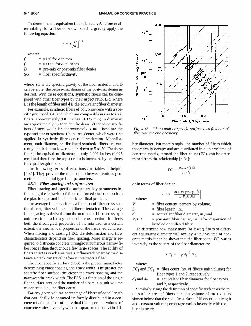
e
roetepeetee tirare02im
fue
s i
eaggc
tareo
ity d
t t tgm
go ol f
ich ofter-
f
r-n-
r
1
o-isth
e fi-
544.1R-54
f
MANUAL OF CONCRETE PRACTICE
To determine the equivalent fiber diameter,d,before or af-ter mixing, for a fiber of known specific gravity apply thfollowing equation:
where:f = .0120 ford in mmf = 0.0005 ford in inchesD = pre-mix or post-mix fiber denierSG = fiber specific gravity
where SG is the specific gravity of the fiber material andcan be either the before-mix denier or the post-mix deniedesired. With these equations, synthetic fibers can be cpared with other fiber types by their aspect ratio, L/d, whL is the length of fiber and d is the equivalent fiber diame
For example, synthetic fibers of polypropylene with a scific gravity of 0.91 and which are comparable in size to stfibers, approximately 0.01 inches (0.025 mm) in diameare approximately 360 denier. The denier of the same sizbers of steel would be approximately 3100. These aretype and size of synthetic fibers, 360 denier, which were fapplied in synthetic fiber concrete production. Monofilment, multifilament, or fibrillated synthetic fibers are curently applied at far lower denier, down to 5 to 50. For thfibers, the equivalent diameter is only 0.001 inches (0.mm) and therefore the aspect ratio is increased by ten tfor equal length fibers.
The following series of equations and tables is help[4.84]. They provide the relationship between various gmetric and material type fiber parameters.
4.5.1—Fiber spacing and surface areaFiber spacing and specific surface are key parameter
fluencing the behavior of fiber reinforced concrete boththe plastic stage and in the hardened final product.
The average fiber spacing is a function of fiber cross-stional area, fiber volume, and fiber orientation. The averfiber spacing is derived from the number of fibers crossinunit area in an arbitrary composite cross section. It affeboth the rheological properties of the mix and, to a cerextent, the mechanical properties of the hardened concWhen mixing and casting FRC, the deformation and flcharacteristics depend on fiber spacing. More energy isquired to distribute concrete throughout numerous narrowber spaces than throughout a few large spaces. The abilfibers to act as crack arrestors is influenced in part by thetance a crack can travel before it intercepts a fiber.
The fiber specific surface (FSS) is the predominant facdetermining crack spacing and crack width. The greaterspecific fiber surface, the closer the crack spacing andnarrower the crack width. The FSS is a function of the sinfiber surface area and the number of fibers in a unit voluof concrete, i.e., the fiber count.
For any given volume percentage of fibers of equal lenthat can ideally be assumed uniformly distributed in a ccrete mix the number of individual fibers per unit volumeconcrete varies inversely with the square of the individua
d fD
SG-------
1 2⁄=
D asm-rer.-
elr, fi-hest--se5es
lo-
in-n
c-e
atsinte.
wre-fi- ofis-
orhehelee
thn-fi-
ber diameter. Put more simply, the number of fibers whtheoretically occupy and are distributed in a unit volumeconcrete matrix, termed the fiber count (FC), can be demined from the relationship [4.84]:
or in terms of fiber denier,
where:V = fiber content, percent by volume,L = fiber length, in.,d = equivalent fiber diameter, in., andP0MD = post-mix fiber denier, i.e., after dispersion o
bundled or collated fiber.To determine how many more (or fewer) fibers of diffe
ent equivalent diameter will occupy a unit volume of cocrete matrix it can be shown that the fiber count,FC, variesinversely as the square of the fiber diameter as:
where:FC1 andFC2 = fiber count (no. of fibers/ unit volume) fo
fiber types 1 and 2, respectively.d1 andd2 = equivalent fiber diameter for fiber types
and 2, respectively.Similarly, using the definition of specific surface as the t
tal surface area of fibers per unit volume of matrix, it shown below that the specific surface of fibers of unit lengand constant volume percentage varies inversely with thber diameter:
FC0.0127 V( )
L d2( )
-------------------------=
FC50.8 V( ) SG( ) 10
3( )L P0MD( )
-----------------------------------------------=
FC1 d2 d1⁄ )2FC2(=
Fig. 4.18—Fiber count or specific surface as a function ofiber volume and geometry

1
s
e as
er
ter is
sp diat. Inat ibanheibe
e, astoringer- toowrrerenro-nstic
te,
d
li-onreon-
oficeCon-r-e,d
heedalr-
ewseen-
dckndd
g-Cch
r
er-
fa-s
ersc-
-
544.1R-55FIBER REINFORCED CONCRETE
where:FSS1 andFSS2 = fiber specific surface for fiber types
and 2, respectively.d1 andd2 = equivalent fiber diameter for fiber type
1 and 2, respectively.Similar expressions have been derived for fiber count (FC)
or fiber specific surface (FSS) as a function of weight dosagrate, volume, specific gravity, denier, and diameter [4.84]shown below:
where:FC = fiber count, fibers/in.3 (divide FC by 16,390 for
mm3 basis)
FSS = fiber specific surface, surface area/in.3 (divideFSS by 16,390 for mm3 basis)
DRT = dosage rate of fiber, lbs/yd3
V = fiber content, percent by volume
L = fiber length, in.
d = equivalent fiber diameter, in.
P0MD = post-mix denier
4.5.2—Graphical solutionFigure 4.18 is a nomograph [4.84] that gives the fib
count,FC, or the fiber specific surface,FSS, of unit lengthfibers as a function of fiber volume and equivalent diame
For example, if a specified volume percentage of fibersentered along the base of the graph, the abscissa, and aified equivalent fiber diameter in inches is chosen on theagonal lines on the graph, then the vertical axis, the ordinof the graph, gives the fiber count on a unit volume basisthis procedure, as in previous equations, it is assumed thbers have a cylindrical shape and circular cross section. Fcount and specific surface for lengths of fiber of other thunit length, one inch (25 mm), can be found by dividing tvalues found on the ordinate of the graph by the actual flength in the appropriate units.
4.6—Applications of SNFRCCommercial use of SNFRC currently exists worldwid
primarily in applications of cast-in-place concrete (suchslabs-on-grade, pavements, and tunnel linings) and facmanufactured products (such as cladding panels, sidshingles, and vaults) [4.85]. Currently, there are two diffent synthetic fiber volume contents used in applicationsday. They are 0.1 to 0.3 percent, which is referred to as lvolume percentage, and 0.4 to 0.8 percent, which is refeto as high-volume percentage. There are also two diffephysical fiber forms. They are monofilament and fibers pduced from fibrillated tape. Most synthetic fiber applicatioare at the 0.1 percent by volume level to control plas
FSS1 d2 d1)⁄ FSS2(=
FC7.5 DRT( ) 10
4–( )
L d2) SG)((
------------------------------------------- 0.0127 V )(
L d2)(
--------------------------3.0 DRT( ) 10
3( )L P0MD )(
----------------------------------------50.8 V( ) SG( ) 10
3( )L P0MD )(
-----------------------------------------------= = = =
FSS2.36 DRT( ) 10
3–( )d SG( )
---------------------------------------------- 0.04 V( )d
------------------- 4.71 DRT( )
P0MD( ) SG( )[ ]1 2⁄-------------------------------------------------- 80 V( ) SG( )1 2⁄
P0MD( )1 2⁄
--------------------------------------= = = =
.
ec--e
fi-er
r
y,
--dt
shrinkage cracking. Uses include precast products, shotcreand cast-in-place elements. Typically, the fiber length is3/4to 21/2 in. (19 to 64 mm) with the predominance of demanfor 3/4 or 11/2 in. (19 or 38 mm) long fibers.
4.6.1—Applications of carbon FRCDue to the current high cost of the carbon fiber, its app
cation has been limited. Suggested applications for carbfiber reinforced concrete [4.86] include: corrugated units fofloor construction, single and double curvature membranstructures, boat hulls, and scaffold boards. The use of carbfiber in combination with other fiber types has been discussed as a means of reducing the overall cost.
Carbon FRC has been successfully used in constructionfree access floor systems used in computer rooms and offautomation system rooms [4.14]. Lightweight carbon FRwith microballoons as aggregate has been applied in the cstruction of the Al Shaheed Monument in Iraq [4.10]. Cabon FRC curtain walls have been installed in thconstruction of a 37 story office building in Tokyo, Japanreportedly resulting in substantial savings in both time anmoney [4.44].
Proponents of carbon FRC suggest that reduction in tminimum dimensions of pipes and boards can be obtainwith the use of carbon fibers. Ignoring economics, structurapplications appear promising. Optimization of manufactuing processes for carbon fibers may bring costs down.
4.6.2—Applications of polypropylene and nylon FRCTo date, most commercial applications of polypropylen
FRC [4.85, 4.88] and nylon FRC have used low denier, lovolume percentage (0.1 percent), monofilament (in the caof polypropylene and nylon) or fibrillated fibers (in the casof polypropylene). These fibers have been applied to nostructural and non-primary load bearing applications.
Current applications include residential, commercial, anindustrial slabs on grade, slabs for composite metal deconstruction, floor overlays, shotcrete for slope stabilizatioand pool construction, precast units, slip form curbs, anmortar applications involving sprayed and plastered portlancement stucco.
4.7—Research needsIn addition to the ongoing pursuit of the goal of developin
cost effective fibers with material properties and fiber geometries that are best suited to particular applications or FRfabrication technologies, there is a need for further researin the following areas:
1. Determine the effect of the addition of various fibetypes on control joint spacing for concrete flatwork.
2. Continue to determine effectiveness of fibers as tempature and shrinkage reinforcement.
3. Develop standardized test procedures for impact and tigue loading to demonstrate performance differenceamong various fiber types.
4. Develop composite applications and design parametusing conventional reinforcement in FRC concrete for strutural applications.
5. Determine the fire resistant properties of fiber reinforced composites.

to,io,
C.,andash
anc
tee
entre
te,
os
ein-
.and
rtien oor-
re
edtan-
,
and
ein-EM
ite
1,
-
inht
e
d
ly-ts,”
d
n
ot-
-e-
ck
I
drch
ial
e
ed
an
d
on
er
n-
erri-
544.1R-56 MANUAL OF CONCRETE PRACTICE
4.8—Cited references4.1 Goldfein, S., “Fibrous Reinforcement for Portland Cement,”Modern
Plastics, Vol. 42, No. 8, 1965, pp. 156-160.4.2 Williamson, G. R., “Response of Fibrous Reinforced Concrete
Explosive Loading,”Technical Report No. 2-48, Department of the ArmyOhio River Division Laboratory, U. S. Corp of Engineers, Cincinnati, OhJan. 1966.
4.3 Morgan, D. R.; McAskill, N.; Richardson, B. W.; and Zellers, R. “A Comparative Evaluation of Plain, Polypropylene Fiber, Steel Fiber, Wire Mesh Reinforced Shotcrete,” Transportation Research Board, Wington D. C., Jan. 1989.
4.4 Ramakrishnan, V., and Bjorn, J. L., “Fatigue Strength and EndurLimit of Plain and Fiber Reinforced Composites—A Critical Review,”Pro-ceedingsof the International Symposium on Fatigue and Fracture in Sand Concrete Structures, Madras, India, Dec. 1991, pp. 381-405.
4.5 Daniel, J. I., and Anderson, E. D., “Acrylic Fiber Reinforced CemComposites,”Third International Symposium on Developments in FibReinforced Cement and Concrete, RILEM Symposium FRC 86, Vol. 1,RILEM Technical Committee 49-TFR, July 1986.
4.6 Hahn, H.; Karl, S.; and Worner, J. D.,Properties of PolyacrylonitrileFiber Reinforced Concrete, SP-105, Session on Fiber Reinforced ConcreBaltimore, Nov. 1986, 13 pp.
4.7 Walton, P. L., and Majumdar, A. J., “Properties of Cement Compite Reinforced with Kevlar Fibres,”Journal of Materials Science, Vol. 13,1978, pp. 1075-1083.
4.8 Gale, D. M.; Riewald, P. G.; and Champion, A. R., “Cement Rforcement with Man-Made Fibers,”International Man-Made Fibres Con-gress, E. I. Du Pont de Nemours and Co., Dornbirn, Austria, Sept. 1986
4.9 Konczalski, P., and Piekarski, K., “Tensile Properties of PortlCement Reinforced with Kevlar Fibers,”Journal of Reinforced Plasticsand Composites, Vol. 1, Oct. 1982, pp. 378-384.
4.10 Akihama, S.; Suenage, T.; and Banno, T., “Mechanical Propeof Carbon Fiber Reinforced Cement Composite and the ApplicatioLarge Domes,” Kajima Institute of Construction Technology, Kajima Cporation, Tokyo, Japan, July 1984.
4.11 Ali, M. A.; Majumdar, A. J.; and Rayment, D. L., “Carbon-FibReinforcement of Cement,”Cement and Concrete Research,Vol. 2, 1972,pp. 201-212.
4.12 Aveston, J.; Mercer, R. A.; and Sillwood, J. M., “Fibre-ReinforcCements—Scientific Foundations for Specifications: Composites—Sdards Testing and Design,”National Physical Laboratory Conference Proceedings, Apr. 1974, pp. 93-103.
4.13 Biggs, A.; Bowen, D. H.; and Kollek, J.,Proceedings of the 2ndInternational Carbon Fibre Conference, the Plastics Institute, London1974.
4.14 Hannant, D. J.,Fibre Cements and Fibre Concretes, John Wiley andSons, Ltd., New York, 1978, 213 pp.
4.15 Nishioka, K.; Yamakawa, S.; and Shirakawa, K., “Properties Applications of Carbon Fiber Reinforced Cement Composites,” Proceed-ingsof the Third International Symposium on Developments in Fiber Rforced Cement and Concrete, RILEM Symposium FRC 86, Vol. 1, RILTechnical Committee 49-TFR, July 1986.
4.16 Waller, J. A., “Carbon Fibre Cement Composites,”Civil Engineer-ing and Public Works Review, Apr. 1972, pp. 357-361.
4.17 Waller, J. A.,Carbon Fibre Cement Composites, SP-44, AmericanConcrete Institute, Detroit, 1974, pp. 143-161.
4.18 Walton, P. L., and Majumdar, A. J., “Cement Based Composwith Mixtures of Different Types of Fibres,”Composites, Sept. 1975, pp.209-216.
4.19 The Condensed Chemical Dictionary, Van Nostrand, RheinholdCompany, New York, 8th ed., p. 635.
4.20 Cook, J. G.,Handbook of Textile Fibers, Morrow Publishing Com-pany, Ltd., Durham, England, 1984, pp. 261-283.
4.21 Moncrieff, R. W.,Man-Made Fibers, John Wiley & Sons, Inc., NewYork, 1959, pp. 324-333.
4.22 Khajuria, A.; Bohra, K.; and Balaguru, P. N.,Long-Term Durabilityof Synthetic Fibers, SP-126, American Concrete Institute, Detroit, 199pp. 851-868.
4.23 Sorenson, W. R., and Campbell, T. W.,Preparative Methods ofPolymer Chemistry, Interscience Publishers, Inc., New York, 1961.
4.24 Golding,Polymers and Resins, D. Van Nostrand Co., 1959, pp. 288289.
-
e
l
-
sf
-
s
4.25 Kobayashi, K., “Development of Fibre Reinforced Concrete Japan,”The International Journal of Cement Composites and LightweigConcrete, Vol. 5, No. 1, Construction Press, Feb. 1983.
4.26 Kobayashi, K. and Cho, R., “Flexural Behavior of PolyethylenFibre Reinforced Concrete,”The International Journal of Cement Compos-ites and Lightweight Concrete, Vol. 3, No. 1, Construction Press, Feb.1981.
4.27 Gale, D. M., and Shin, H., “Cement Matrix Composites anMethod for Making Same,” U.S. Patent 4,608,089, Aug. 26, 1986.
4.28 Gale, D. M.; Shah, A. H.; and Balaguru, P. N.,Oriented Polyethyl-ene Fibrous Pulp Reinforced Cement Composites, SP-124, American Con-crete Institute, Detroit, 1990, pp. 61-70.
4.29 Gale, D. M.; Guckert, J. R.; and Shelburne, S. S., “Oriented Poethylene Pulp for Asbestos Replacement in Cement Building ProducTextile Composites in Building Construction—Part I,Cement-Based Com-posites and Geotextiles, FITAT, Lyon, France, July 1990, pp. 47-56.
4.30 Dave, N. J., and Ellis, D. G., “Polypropylene Fibre ReinforceCement,”The International Journal of Cement Composites, Vol. 1, No. 1,May 1978, pp. 19-28.
4.31 Rice, E., Vondran, G. and Kunbargi, H., “Bonding of FibrillatedPolypropylene Fibers to Cementitious Materials,”Materials ResearchSociety Proceedings, Pittsburgh, Vol. 114, 1988, pp. 145-152.
4.32 Mai, Y. W.; Andonian, R.; and Cotterell, B., “Thermal Degradatioof Polypropylene Fibers in Cement Composites,”International Journal ofComposites, Vol. 3, No. 3, Aug. 1980, pp. 149-155.
4.33 “Standard Specification for Fiber Reinforced Concrete and Shcrete,”ASTM Standards for Concrete and Aggregates, Vol. 04.02, ASTM C1116, 1989.
4.34 Zollo, R. F.,Collated Fibrillated Polypropylene Fibers in FRC, SP-81, American Concrete Institute, Detroit, 1984, pp. 397-409.
4.35 Zollo, R. F.; Ilter, J. A.; and Bouchacourt, G. B., “Plastic and Drying Shrinkage in Concrete Containing Collated Fibrillated PolypropylenFibre,” Third International Symposium on Developments in Fibre Reinforced Cement and Concrete, RILEM Symposium FRC 86, Vol. 1, RILEMTechnical Committee 49-TFR, July 1986.
4.36 “Standard Test Method for Flexural Toughness and First-CraStrength of Fiber Reinforced Concrete,”ASTM Standards for Concrete andMineral Aggregates, Vol. 04.02, ASTM C 1018.
4.37 “Measurement of Properties of Fiber Reinforced Concrete,” ACJOURNAL, ACI Committee Report 544.2R 78, July 1978.
4.38 Dahl, A., “Plastic Shrinkage and Cracking Tendency of Mortar anConcrete Containing Fibermesh,” FCB Cement and Concrete ReseaInstitute, Trondhein, Norway,Report ISBN No: 82-595-4060-6 Nov. 9,1985, pp. 1-23.
4.39 Kraai, P., “A Proposed Test to Determine the Cracking PotentDue to Drying Shrinkage of Concrete,”Concrete Construction Publica-tions, Addison, Sept. 1985, pp. 775-778.
4.40 Vondran, G., and Webster, T.,The Relationship of PolypropyleneFiber Reinforced Concrete to Permeability, SP 108, American ConcreteInstitute, Detroit, 1988, pp. 85-97.
4.41 Padron, I., and Zollo, R. F., “Effect of Synthetic Fibers on VolumStability and Cracking of Portland Cement Concrete and Mortar,”ACIMaterials Journal, Vol. 87, No. 4, July-Aug. 1990, pp. 327-332.
4.42 Daniel, J. I., and Shah, S. P., “Thin Precast Fiber ReinforcCement Panels,”Materials and Membrane Behavior, Proceedings of theSessions at Structures Congress, ’87, Structural Division of the AmericSociety of Civil Engineers, Aug. 17-20, 1987.
4.43 Nanni, A., “Properties of Aramid Fiber Reinforced Concrete anSIFCON,” J. of Materials in Civil Engineering, ASCE, Vol. 2, No. 1, Feb.1992, pp. 1-15.
4.44 “Carbon-Fiber Reinforced Concrete Curtain Walls,”Concrete Con-struction, Jan. 1986, p. 49.
4.45 Banthia, N., and Ohama, Y., “Dynamic Tensile Fracture of CarbFiber Reinforced Cements,”Proc., Int'l Conf. on Recent Developments inFRC, Cardiff, Sept. 1989, pp. 251-260.
4.46 Ohama, Y.; Amano, M.; and Endo, M., “Properties of Carbon FibReinforced Cement with Silica Fume,”Concrete International, Vol. 7, No.3, 1985, pp. 58-62.
4.47 Sridhara, S.; Kumar, S.; and Sinare, M. A., “Fiber Reinforced Cocrete,”Indian Concrete Journal, Oct. 1971, pp. 428-442.
4.48 Paramasivan, P.; Nathan, G.; Wong, K.; and Liu, P., “Study of FibReinforced Concrete,” First Australian Conference on Engineering Mateals, The University of New South Wales, 1974, pp. 333-350.

etic
ates
FiberCivil
rced-
For-975.tigue
on
rete,
gueCon-il,
, V.,
ork,
vior
. 69-
ete,”lia,
the
lene
rced
-
merh,
ase-rd,
on-.
ein-
ness
ein-oad-
s,
ent
ced-
E.;iber
.,h
te,
y-ce
.,s-ET,
ber
ete
ast
iber
te-
y-on-
nd
ck-oneb.
ral
ne
ofedn- nat-er
ower
nu-en
RC.
544.1R-57FIBER REINFORCED CONCRETE
4.49 Wang, Y., and Backer, S., “An Experimental Study of SynthFiber Reinforced Cementitious Composites,”Journal of Materials Science,(Accepted for publication).
4.50 Goldfein, S., “Impact Resistant Concrete Admixture,” United StPatent 3,645,961, Feb 29, 1972.
4.51 Brochenbrough, T. W., and Davis, C. F., “Progress Report on Reinforced Concrete,” The Delaware State Highway Department, Engineering Department, University of Delaware, Newark, Jan. 1970.
4.52 Brochenbrough, T. W., and Patterson, D. N., “Fiber ReinfoMethacrylate Polymer Concrete,” ACI JOURNAL, July-Aug. 1982, pp. 325328.
4.53 Casamatta, D. M., “Synthetic Fiber Reinforced Concrete,”CodeNews, Vol. 1986, No. 6, Nov.-Dec. 1986.
4.54 Jakel, G. R., “Fiber Reinforced Concrete Products and Theirmation; Polyesters, Cellulose Pulp,” U.S. Patent #US3899344, Aug. 1
4.55 Nagabhushanam, M.; Ramakrishnan, V.; and Vondran, G., “FaStrength of Fibrillated Polypropylene Fiber Reinforced Concrete,”Trans-portation Research Record 1226, National Research Council, WashingtD.C., 1989, pp. 36-47.
4.56 Ramakrishnan, V.; Gollapudi, S.; and Zellers, R.,PerformanceCharacteristics and Fatigue of Polypropylene Fiber Reinforced ConcSP-105, American Concrete Institute, Detroit, 1987, pp. 159-177.
4.57 Ramakrishnan, V.; Wu, G. Y.; and Hosalli, G., “Flexural FatiStrength, Endurance Limit, and Impact Strength of Fiber Reinforced crete,”Transportation Research Record 1226, National Research CouncWashington D. C., 1989, pp. 17-24.
4.58 Vondran, G. L.; Nagabhushanam, M.; and Ramakrishnan“Fatigue Strength of Polypropylene Fiber Reinforced Concretes,”FiberReinforced Cements and Concretes: Recent Developments, edited by R. N.Swamy and B. Barr, Elsevier Applied Science, London and New Y1990, pp. 533-543.
4.59 Ramakrishnan, V.; Wu, G. Y.; and Hosalli, G., “Flexural Behaand Toughness of Fiber Reinforced Concretes,”Transportation ResearchRecord 1226, National Research Council, Washington D. C., 1989, pp77.
4.60 Guirguis, S., and Potter, R. J., “Polypropylene Fibres in ConcrTechnical ReportTR/F90, Cement and Concrete Association of AustraMay 1985, 21 pp.
4.61 Malisch, W. R., “Polypropylene Fibers in Concrete—What DoTests Tell Us?,”Concrete Construction, Apr. 1986, pp. 363-368.
4.62 Hannant, D. J.; Zonsveld, J. J.; and Hughes, D. C., “PolypropyFilm in Cement Based Materials,”Composites, Vol. 9, No. 2, Apr. 1978,pp. 83-88.
4.63 Mindess, S., and Vondran, G., “Properties of Concrete Reinfowith Fibrillated Polypropylene Fibres under Impact Loading,”Cement andConcrete Research, Pergamon Journals, Ltd., USA, Vol. 18, 1988, pp. 109115.
4.64 Bhargava, J., and Rhenstrom, A., “Dynamic Strength of PolyModified and Fiber Reinforced Concrete,”Cement and Concrete ResearcVol. 7, 1977, pp. 199-208.
4.65 Fairweather, A. D., “The Use of Polypropylene Fiber to IncreImpact Resistance of Concrete,”Proc. Int’l Bldg. Exhibition Conf. on Prospects for FRC Materials, London, 1971, Bldg. Research Station, Watfo1972, pp. 41-43.
4.66 Banthia, N.; Mindess, S.;and Bentur, A., “Impact Behavior of Ccrete Beams,”Materials and Structures (Paris), Vol. 20, No. 119, 1987, pp293-302.
4.67 Banthia, N.; Mindess, S.; and Bentur, A., “Behavior of Fiber Rforced Concrete Beams under Impact Loading,”Proc., Sixth Int’l Conf. onComposite Materials,(ICCM-VI), London, 1987.
4.68 Mindess, S.; Banthia, N.; and Cheng, Y., “The Fracture Toughof Concrete under Impact Loading,”Cement and Concrete Research,Vol.20, 1987, pp. 231-241.
4.69 Mindess, S.; Banthia, N.; and Bentur, A., “The Response of Rforced Concrete Beams with a Fibrous Concrete Matrix to Impact Ling,” Int’l Journal of Cement Composites (UK), Vol. 8, No. 3, 1986, pp.165-170.
4.70 Naaman, A. E.; Shah, S. P.; and Throne, J. L.,Some Developmentin Polypropylene Fibers for Concrete, SP-81, American Concrete InstituteDetroit, 1984.
4.71 Swamy, R. N., and Stavrides, H., “Influence of Fiber Reinforcemon Restrained Shrinkage and Cracking,” ACI JOURNAL, Vol. 76, No. 3,Mar. 1979, pp. 443-460.
4.72 Ramakrishnan, V., “Materials and Properties of Fiber ReinforConcrete,”Proceedingsof the International Symposium on Fiber Reinforced Concrete, Madras, India, Dec. 1987, pp. 2.3-2.23.
4.73 Gopalaratnam, V. S.; Shah, S. P.; Batson, G. B.; Criswell, M.Ramakrishnan, V.; and Wecharatana, M., “Fracture Toughness of FReinforced Concrete,”ACI Materials Journal, Vol. 88, No. 4, July-Aug.1991, pp. 339-353.
4.74 Morgan, D. R.; McAskill, N.; Carette, G. G.; and Malhotra, V. M“Evaluation of Polypropylene Fiber Reinforced High Volume Fly AsShotcrete,” CANMET International Workshop on Fly Ash in ConcreCalgary, Alberta, Oct. 1990.
4.75 Morgan, D. R., “Freeze-Thaw Durability of Steel and Polyproplene Fiber Reinforced Shotcrete,” CANMET/ACI International Conferenon Durability of Concrete, Montreal, Quebec, Aug. 1990.
4.76 Malhotra, V. M.; Carette, G. G.; Bilodeau, A.; and Dibble, D“Fiber Reinforced High Volume Fly Ash Shotcrete for Controlling Aggresive Lactates from Exposed Rock Surfaces and Mine Tailings,” CANMJune1989.
4.77 Grzybowski, M., and Shah, S. P., “Shrinkage Cracking in FiReinforced Concrete,”ACI Materials Journal, Vol. 41, No. 148, Sept.1989.
4.78 Vondran, G.,Making More Durable Concrete With PolymericFibers, Mather International Conference, SP-100, American ConcrInstitute, Detroit, May 1987, pp. 377-396.
4.79 Vondran, Gary L., “Plastic Fiber Reinforced Concrete,”Proceed-ings of Concrete Technology Seminar 3, Michigan State University, ELansing, Feb. 1988, pp. 8.1-8.23.
4.80Underwriters Laboratory Fire Resistance Directory, R11194, DTD,Oct. 15, 1990.
4.81 Kobayashi, K., and Cho, R., “Flexural Characteristics of Steel Fand Polypropylene Fiber Hybrid Reinforced Concrete,”Composites, Vol.13, 1982, pp. 164-168.
4.82 Banthia, N., and Sheng, J., “Micro-Reinforced Cementitious Marials,” Materials Research Society Symposium Proceedings, Vol. 211, Bos-ton, Nov. 1990.
4.83 Raithby, K. D.; Galloway, J. W.; and Williams, R. T., “Polyproplene Reinforced Cement Composites for Surface Reinforcement of Ccrete Structures,”The International Journal of Cement Composites aLightweight Concrete, Vol. 5, No. 3, Aug. 1983, pp. 193-197.
4.84 Zollo, R. F., “Synthetic Fiber Reinforced Concrete: Some Baground and Definitions,” Seminar on Polymeric Fibers: Their Effect Concrete and Concrete Cracking,” World of Concrete 89, Atlanta, F1989.
4.85 Zollo, R. F., and Hays, C. D., “Fibers vs. WWF as Non-StructuSlab Reinforcement,”Concrete International,American Concrete Institute,Vol. 13, No. 11, Nov. 1991, pp. 50-55.
4.86 Ramakrishnan, V. S.; Feldman, R. F.; and Beaudoin, J. J.,ConcreteScience, Treatise on Current Research, Heyden & Sons, Ltd., 1981.
4.87 Hannant, D. J., “Review of the Present Scene,”Proceedingsof theSymposium on Fibrous Concrete, London, Apr. 1980.
4.88 Krenchel, H., and Shah, S. P., “Applications of PolypropyleFibers in Scandinavia,”Concrete International, Vol. 7, No. 3, Mar. 1985.
CHAPTER 5—NATURAL FIBER REINFORCEDCONCRETE (NFRC)
5.1—IntroductionDiscontinuous short fibers are widely used in both types
FRC all over the world. In this chapter, attention is focuson the use of naturally occurring fibers for reinforcing cocretes, mortars, and cements. Concretes reinforced withurally occurring fibers are generally termed natural fibreinforced concrete (NFRC).
Many natural reinforcing materials can be obtained at llevels of cost and energy using locally available manpowand technical know-how. Such fibers are used in the mafacture of low fiber content FRC and occasionally have beused in the manufacture of thin sheet high fiber content F

tura
beenre dt protedss,
s are and rein
ein-tif- foral fi-in (b
ction
ble of
andibed.re-
ablytin-all
ro-his-inen-
iedar,
544.1R-58 MANUAL OF CONCRETE PRACTICE
These fibers are typically referred to as unprocessed nafibers (UNF).
However, other natural fibers are available that have processed to enhance their properties. These fibers arived from wood by chemical processes such as the krafcess. Kraft pulp fibers are used in sophisticamanufacturing processes, such as the Hatschek proceproduce thin sheet high fiber content FRC. These fibertypically referred to as processed natural fibers (PNF)concretes made from them as processed natural fiberforced concretes (PNFRC).
Although historically many fibers have been used to rforce various building materials, until recently little scienic effort has been devoted to the use of natural fibersreinforcement. The use of some of the best known naturbers such as sisal, coconut, sugarcane bagasse, plantanana), palm, etc., have mostly been limited to the produof fabrics, ropes, mats, etc.
l
e--
to
-
a-
In this report, the various types of natural fibers availafor reinforcing concretes, the mix proportions, the methodmixing, handling and placing, and the properties of fresh hardened natural fiber reinforced concretes are descrAdditionally, some of the applications of the NFRC are psented.
5.2—Natural fibers5.2.1—Unprocessed natural fibersUnprocessed natural fibers are available in reason
large quantities in many countries and represent a conuously renewable resource. UNFs require relatively smamounts of energy and technical know-how for their pduction compared to some other types of fibers. In the torical context, the use of raw natural fibers construction substantially preceded the advent of convtional reinforced concrete. Straw-reinforced, sun-drmud bricks for wall construction, and horse hair in mort
Table 5.1— Typical properties of natural fibers
Fiber type Coconut Sisal
Sugarcane
Bagasse Bamboo Jute FlaxElephant
grassWaterreed Plantain Musamba
Woodfiber(kraftpulp)
Fiber length,in. 2-4 N/A N/A N/A 7-12 20 N/A N/A N/A N/A 0.1-0.2
Fiber diameter, in.
0.004-0.016 N/A 0.008-
0.0160.002-0.016
0.004-0.008 N/A N/A N/A N/A N/A 0.001-
0.003
Specific gravity
1.12-1.15 N/A 1.2-1.3 1.5 1.02-
1.04 N/A N/A N/A N/A N/A 1.5
Modulus ofelasticity, ksi
2750-3770
1880-3770 2175-2750 4780-
58003770-4640 14,500 710 750 200 130 N/A
Ultimate tensile
strength, psi
17,400-29,000
40,000-82,400
26,650-42,000
50,750-72,500
36,250-50,750 145,000 25,800 10,000 13,300 12,000 101,500
Elongation atbreak,percent
10-25 3-5 N/A N/A 1.5-1.9 1.8-2.2 3.6 1.2 5.9 9.7 N/A
Water absorption,
percent130-180 60-70 70-75 40-45 N/A N/A N/A N/A N/A N/A 50-75
Note: N/A = properties not readily available or not applicable.Metric equivalents: 1 in. = 25.4 mm; 1 ksi = 1000 psi = 6.895 MPa
Table 5.2— Mechanical properties of several types of fibers
Type of fiberAverage diameter,
in.Average length,
in.Absorption after24 hr, percent
Average fiber density (SG)
Average tensilestrength, psi
Average bondingstrength, psi
Averageelongation,
percentBagasse 0.020 1.38 122.5 0.639 3,570 36 N/ACoconut 0.027 11.02 58.5 0.580 8,825 40 2.600Jute 0.004 15.75 62.0 1.280 53,500 20 N/AMaguey 0.014 15.75 63.0 1.240 54,400 N/A N/ALechuguilla 0.014 15.75 102.0 1.360 54,100 N/A N/ABanana 0.011 3.70 276.0 0.298 10,960 35 3.000Guaney (palm) 0.017 17.44 129.9 1.195 50,000 40 2.880Bamboo Variable Variable 51.0 0.720 54,680 45 1.800
Note: N/A = Not availableMetric equivalents: 1 in. = 25.4 mm; 1 psi = 0.006895 MPa

n
gm
e eioa nssil
eeb.
rcen
h usel
pl
fieiehe
ic
a
gth e
e
f
sini
the
e isndith20nd ofietyhed-
dg
u-oes ars-p-l
s.,sortar.
ryoutersand
ric-f
re-rean-
ing re-u-
-e-fore-
al,theallyales fi-
544.1R-59FIBER REINFORCED CONCRETE
are typical examples of how natural fibers were used loago.
In the late 1960s, a systematic evaluation of the enneering properties of natural fibers, and of cement coposites made with these fibers was undertaken. Tresults of these investigations indicated that these fibcould be used successfully to make thin cement sheetswalls and roofs. Appropriate manufacturing processwere subsequently developed for commercial productin various countries of Central America, Africa, and AsiProducts made with portland cement and unprocessedural fibers such as coconut coir, sisal, sugarcane bagabamboo, jute, wood, and vegetable fibers have been tefor their engineering properties and possible use in buings in at least 40 different countries [5.1-5.9]. Althougthe results were encouraging, some deficiencies wfound in their durability. These seem to have resultfrom the reaction between the cement paste and the fiand swelling of the fibers in the presence of moisturenumber of researchers are now investigating remedmeasures for improving durability.
5.2.2—Processed natural fibersProcessed natural fibers have been used in comme
production for the manufacture of thin-sheet fiber reinforccement products since the mid-1960s initially as an adjuto asbestos and since the early 1980s as a sole reinforcinber. Experimental use of these fibers greatly precedes tlarge scale commercial use. The first experiment with theof wood pulp as a replacement for asbestos in asbestoment dates back to World War I. The Norwegian fiber cment industry was forced to manufacture wood pureinforced cement sheets for commercial use during thisriod because they were unable to obtain their usual suppof asbestos due to the war.
5.2.3—Mechanical properties of natural fibers5.2.3.1Mechanical properties of unprocessed natural
bers—Information on mechanical properties of unprocessnatural fibers is available [5.5-5.40]. In this section, a brsummary of the results of research to determine the mecical properties of various types of unprocessed natural fibis presented. The types of fibers for which the mechanproperties have been evaluated are given in Table 5.1. Abrief description for some of the more commonly found nural fibers is presented below.
a.Coconut fiber. A mature coconut has an outer coverinmade of fibrous material. This part of the coconut, called husk, consists of a hard skin and a large amount of fibersbedded in a soft material. The fibers can be extracted simby soaking the husk in water to decompose the soft matesurrounding the fibers. This process, called retting, is widused in the less developed countries. Alternatively, a mchanical process [5.10] can be used to separate the fibCoconut cultivation is restricted to the tropical regions of Arica, Asia, and Central America.
b. Sisal fiber. In Australia, sisal fibers have been succefully used for making gypsum plaster sheets [5.7]. A conserable amount of research has been carried out in Swededeveloping good quality concrete products reinforced w
g
i--
hersforsn.at-se,tedd-hredersAial
ialdct
g fi-eirse ce--
pe-ies
-df
an-rsal
t-
em-plyriallye-ers.-
s-d- for
th
sisal fibers [5.9]. These fibers are stronger than most of other natural fibers, as can be seen from Table 5.1.
c. Sugar cane bagasse fiber. Sugar cane is cultivated inboth tropical and sub-tropical regions. Sugar cane bagassthe residue remaining after the extraction of the juice acontains about 50 percent fiber and 30 percent pith wmoisture and soluble solids constituting the remaining percent. In order to obtain good quality fibers, the pith aother solids are removed from the fibers. The propertiesbagasse fibers depend, to a very large extent, on the varof the sugar cane, its maturity, and on the efficiency of tmilling plant. The properties given in Table 5.1 are consiered to be typical.
d. Bamboo fiber. Bamboo belongs to the grass family ancan grow to a height of 50 ft (15 m) with diameters varyinwithin the range of 1 to 4 in. (25 to 100 mm). It grows natrally in tropical and sub-tropical regions. Dried bambostems are commonly used for building temporary structursuch as scaffolding. They may also be fabricated to formcontinuous reinforcing material for concrete. Bamboo fibeare strong in tension (Table 5.1) and can be used as a reinforcing material. However, they have a high water absortion capacity, low modulus of elasticity, and speciaequipment may be needed to extract them from the stem
e. Jute fiber. Jute is grown mainly in India, BangladeshChina, and Thailand. It is grown solely for its fiber, which itraditionally used for making ropes and bags to transpgrains and other materials ranging from cement to sugStrong in tension (Table 5.1), jute fiber can also be used in acement matrix. The process of obtaining jute fibers is vesimple. Mature plants are cut and soaked in water for ab4 weeks, which completely decomposes the bark. The fibthus exposed are then stripped from the stem, washed, dried.
f. Flax. Flax is a slender and erect plant grown mainly foits fiber. Both the tensile strength and the modulus of elastity of flax are extremely high [5.13] compared to those oother natural fibers, as may be seen from Table 5.1.
g. Other vegetable fibers. Of the various vegetable fibers,only a few have been found to be potentially suitable as inforcing materials. The mechanical properties of the mopromising fibers, namely elephant grass, water reed, pltain, and musamba, are listed in Table 5.1. Investigationshave also been carried out to explore the possibility of usother natural fibers such as palm fiber and akwara fiber asinforcing materials for concrete [5.14]. These fibers are usally removed manually from the stem of the plant.
5.2.3.2 Mechanical properties of processed natural fibers—Processing of plant materials to extract the fibers is rferred to as pulping and the principal plant materials used pulping are trees. Pulping involves breaking of the bond btween fibers in solid softwoods and hardwoods.
Pulping processes are classified as either full-chemicsemi-chemical, or mechanical depending on the nature of defiberization process. Mechanical pulps are made essentiby grinding the wood to separate the fibers, while in chemicpulps the wood is chipped into approximately 1 inch cuband cooked in alkalis to dissolve the material that holds the

544.1R-60 MANUAL OF CONCRETE PRACTICE
Fig. 5.1—A schematic representation of the substructure of a tree
bin by
th alksseemrcelps
cetel. In-
MPentelyodsica fi-od
ey.
lized ces.sta, btheon
rdmerlyng ibera-ard
asinflu-sed
ed.inghen
, for
0heydi- toies
Ina-igh
ce- ofdedingrmr is beornd
orol-ac-ce--
fi-andter. torald. of
sed ofro-et
bers together. Semi-chemical pulps are made with a comtion of chemical cooking, which softens the fiber, followedmechanical treatment to separate the fibers.
It has been found that those components of the woodare removed in the chemical process are susceptible tolis and are responsible for the degradation of unprocenatural fiber reinforced cements and concretes. Thus chcal (kraft) pulps are more commonly used for the reinfoment of cement. Typical mechanical properties of kraft puare also included in Table 5.1.
Figure 5.1 briefly illustrates the structure of wood. A pieof clear timber may attain a tensile strength of approxima10 ksi (69 MPa). But lumber pieces often contain defectsdividual fibers which constitute the reinforcing unit of timber may have tensile strengths as high as 100 ksi (690 or more [5.33]. Cellulose, the primary chemical constituof natural fibers, exhibits a tensile strength of approxima930 ksi (6400 MPa). Among commercial trees, softwoare the source of the so-called long fibers with typlengths ranging from 0.1 to 0.3 in. (2 to 7 mm). Softwoodbers have widths ranging from 15 to 80 microns. Hardwoyield fibers that, on the average, are about1/3 to
1/2 the lengthand about1/2 the width of softwood fibers. Even within thsame tree species, fiber strengths can vary considerabl
5.3—Unprocessed natural fiber reinforcedconcrete
5.3.1—Materials and mixing5.3.1.1 Mix proportions—Mix proportions for unproc-
essed natural fiber reinforced concrete cannot be generasince there are a variety of natural fibers that can be usconjunction with the other standard ingredients such asment, pozzolans, fine aggregates, water, and admixture
The types of natural fibers that can be used with these dard ingredients include: bagasse, sisal, jute, coconutnana, and palm. A brief description for each of constituents which is used for obtaining fiber reinforced ccrete is outlined below.
5.3.1.2Cement—A cement that meets the ASTM standaspecification C 150 or C 595 can be used. The type of cerecommended is Type I, although Type III (high-eastrength) cement can be used in order to reduce hardenitardation caused by the glucose present in most natural f
5.3.1.3Aggregates—The aggregates should meet the gdation requirements specified by ASTM C 33, StandSpecification for Concrete Aggregates.
a-
ata-di--
y-
a)t
l
s
edin-
n-a-
-
nt
re-rs.
5.3.1.4Water and admixtures—The water to be used for themix should be clean and of good quality. Admixtures suchaccelerating agents may be used in order to decrease the ence of the glucose retardant. If mild steel rebars are not uas additional reinforcement, calcium chloride could be usWater-reducing admixtures and high-range water-reducagents can be added in order to increase the workability wplastering. The use of organic-microbiocide is encouragedthe prevention of bacterial attack of organic fibers.
5.3.1.5 Fibers—The length of fibers may vary from 1 to 2in. (25 to 500 mm). Because fibers are natural materials, tare not uniform in diameter and length. Typical values of ameter for unprocessed natural fibers vary from 0.0040.03 in. (0.10 to 0.75 mm) [5.2]. The mechanical propertof fibers are summarized in Table 5.2.
5.3.1.6Methods of mixing—The two methods of mixingand placing are (1) wet mix and (2) dry-compacted mix.the wet mix, a low volume fraction of fibers is used. The wter to be added to the mix has to take into account the hnatural water content in the natural fibers. The mixing produre must comply with ASTM C 94 process and portionsACI 304 recommendations. Trial batches are recommenand a batching plant is required. The recommended mixprocedure is to add cement with water and additives to foa slurry. Then the fine aggregates are added. Finally, fibeadded and dispersed into the slurry. The sampling is todone according to ASTM Practice C 172 and C 685. Fcompressive and flexural strength testing, ASTM C 39 aC 78 are to be followed.
The dry-compacted mix is generally used for industrialsemi-industrial projects. In the dry-compacted mix, the vume fraction of fiber used is about 10 times the volume frtion used in wet mix. The fibers are in a saturated-surfadry condition for this type of mix. Trial batches are recommended. The recommended mixing procedure is to addbers in saturated-surface-dry condition to the cement aggregates and then add a very limited amount of waMixing can be done by hand, although mixing accordingASTM C 94 is recommended. For compressive and flexustrength, ASTM C 39 and ASTM C 78 are to be followeThe dry mix samples are cast followed by the applicationpressure since very little or no water is added to the mix.
The volume percentage of unprocessed natural fibers uin a mix varied from 3 to 30 percent depending on the typefiber used and the manufacturing procedure. Typical mix pportions for coconut fiber reinforced concrete for both the wmix and the dry-compacted mix are presented in Table 5.3.

-
fi-edmagtnifers inbod thelar undis
t- thrs.atctn-
544.1R-61FIBER REINFORCED CONCRETE
Table 5.3— Mix proportions for wet mix and dry-compacted mix
Ingredient Wet mixDry-compacted
mix
Cement, lb/yd3 925-1000 880-925
Coconut fiber, lb/yd3 30 370
Sand, lb/yd3 2500 2500
Water-in fiber, lb/yd3
-added, lb/yd3
3.5(estimate of
natural condition)
630
460(estimate of
saturated-surface-dry condition)
800
Additives-Calcium chloride, lb-Microbiocide, oz-Water reducers
351.9
none
352.1
none
Metric equivalents: 1 lb/yd3 = 0.593 kg/m3; 1 lb = 0.454 kg; 1 oz = 28.35 g
,
Fig. 5.2—Flexural strength and toughness versus fiberweight fraction for cements and mortars reinforced withwood fiber (Kraft pulp)
h-
uinr
--
e I
-
ad
x-ed
n oflingffectd todi-
5.3.2—Properties of unprocessed natural fiber reinforced concrete
5.3.2.1General—The properties of unprocessed natural ber reinforced concrete, like those of any fiber reinforcconcrete, are affected by a large number of factors. The jor ones are listed in Table 5.4. Clearly, the type and lenof fibers, as well as the volume fraction, are the most sigicant factors. Test results [5.10] show that for natural fibthe minimum fiber addition to provide some improvementthe mechanical properties of the cement composite is a3 percent by volume. The impact resistance is increasemost cases regardless of the fiber volume fraction, but oproperties are not improved significantly and remain simito plain concrete. The properties of fresh and hardenedprocessed natural fiber reinforced concretes are briefly cussed in the following sections.
5.3.2.2Fresh concrete—The addition of unprocessed naural fibers to concrete leads to reduced workability due toincreased surface area and water absorption of the fibeis important, however, that the mix be workable. A mix this too stiff or too dry could lead to an inadequately compaed final product which is likely to contain voids and/or ho
-
t
t
eycombs. A mix that is too wet will, on the other hand, leto unnecessary strength reduction.
The other important aspect is “balling” of fibers. The etent to which balling may occur in a given mix is determinby the type and length of fibers used, the volume fractiofibers, and the maximum size of the aggregate. Balshould not be allowed to occur as it has a detrimental eon the strength. Certain mixing methods can be employeminimize the balling effect. Normally, the progressive ad
Table 5.4— Factors affecting properties of naturalfiber reinforced concretes
Factors Variables
Fiber type Coconut, sisal, sugarcane bagasse, bamboojute, wood, vegetables (akwara, elephantgrass, water reed, plantain, and musamba)
Fiber geometry Length, diameter, cross-section, rings, andhooked ends
Fiber form Mono-filament, strands, crimped, and single-knotted
Fiber surface Smoothness, presence of coatings
Matrix properties Cement type, aggregate type and grading,additive types
Mix proportioning Water content, workability aids, defoamingagents, fiber content
Mixing method Type of mixer, sequence of adding constitu-ents method of adding fibers, duration andspeed of mixing
Placing method Conventional vibration, vacuum dewateringfor sprayed-up member, vacuum-press dewa-tering for slurry-dewatered member, extru-sion and guniting
Casting technique Casting pressure
Curing method Conventional, special methods

en-
544.1R-62 MANUAL OF CONCRETE PRACTICE
Fig. 5.3—Relationship between water absorption and dsity of slurry-dewatered softwood Kraft fiber-cement composites at different weight fractions
th. ua
dce
-
d efoter-ma conter-
cal
-ee
ref
tion of fibers at the end of the mixing process, after the oingredients have been mixed, reduces the balling effectso, the use of high-range water-reducing admixtures is foto substantially increase workability without adversely fecting strength.
Depending upon the amount of fibers and the methomixing (dry batch or wet batch), unit weight may be reduto 94 lb/ft3 (1500 kg/m3) (compared to normal concretwhich is 145 to 155 lb/ft3 (2300 to 2500 kg/m3). The work-ability of the dry-compacted mix is normally poor.
5.3.2.3Hardened concrete—One of the important properties of the hardened composite is its strength. Since the uinforced cement mortar matrix possesses adequate strefor many applications, but is brittle, it is customary to stuthe influence of fibers on the increased ductility that canachieved. Apart from strength, other aspects such as dmation under load (stiffness), durability, cracking characistics, energy absorption, water tightness, and therproperties should also be evaluated. The most importanttribution of the fibers can be rationally evaluated by demining the fracture toughness of the composite [5.14].
Table 5.5 shows the strength characteristics of a typi
le noe in an.dem
ria adedeialnd
d-
r
e--ysbehe
composite, reinforced with jute fibers [5.11]. From this tabit can be seen that, in general, compressive strength issignificantly affected by the addition of fibers, while tensiland flexural strength and toughness are all substantiallycreased. Furthermore, for a particular fiber there existsoptimum value for both volume fraction and fiber lengthDetailed information on the behavior of composites mawith jute, coconut, sisal, bagasse, bamboo, flax, and soother vegetable fibers can be found in references 5.11-5.22.
As mentioned earlier, a successful construction mateshould possess desirable serviceability characteristics indition to strength. A number of investigators have studivarious natural fiber reinforced concretes to understand thbehavior in terms of permeability, water absorption, thermconductivity, sound transmission, linear expansion, a
erAl-ndf-
ofed
nre-ngthybe
combustibility. Typical results of these properties, are givenin Tables 5.6 and 5.7 [5.17, 5.21].
-
Fig. 5.4—Effects of moisture content on flexural strengthand toughness of wood reinforced cement at different fibercontents
r-
l-
t
-
e
l-
r
Unfortunately, the amount of available test data on the durability of unprocessed natural fiber reinforced concrete arlimited. The following observations can, nevertheless, bmade, based on the existing literature [5.13].
a. Unprocessed natural fiber reinforced concrete is movulnerable than other fiber reinforced concretes in terms odurability. The highly alkaline pore-water in the concreteseems to deteriorate the fibers.
b. Durability can be substantially improved by replacing40 to 50 percent of the cement with silica fume, since the adition of silica fume reacts with lime and considerably re-duces the alkalinity of the pore-water.
c. Improved durability can be achieved by coating the fibewith suitable chemicals such as formic and stearic acid.
5.3.2.4Placing and finishing—The placing and finishingof the unprocessed natural fiber reinforced concrete is dpendent on the method of mixing used (wet mix or dry-compacted mix). Placing of the wet mix may be achieved busing conventional equipment. Internal or external vibratorshould be used. Other properties such as workability can measured by the slump test or the K-slump tester as per t

544.1R-63FIBER REINFORCED CONCRETE
Table 5.5— Effect of fiber length and volume fraction on strength parameters of jute-fiber reinforcedcement composites
Mix ratiocement/sand
Fibervolumefraction,percent
Fiberlength,in.
Compressive strength, psi
Tensilestrength, psi
Modulus ofrupture, psi
Flexuraltoughness,
in.-lb
Compressive Young’s
modulus, ksi
TensileYoung’s
modulus, ksi
1:0
01234222
—1.01.01.01.00.50.71.5
45605175435054305075443541604520
175200285300245250340255
410540650555480565600640
0.34.97.76.66.15.87.47.3
22502050180018501900220016001700
14001450170016001650150014501350
1:1
02222
—0.50.71.01.5
55705430470547504055
295365315315305
610815730650580
0.57.88.99.77.2
21502050205018001250
22502600195021002550
1:2
02222
—0.50.71.01.5
50704055416547103620
305335360295235
545645670570545
0.47.38.97.16.6
17501450195020502200
26003300325023002400
Metric equivalents: 1 in. = 25.4 mm; 1 ksi = 1000 psi = 6.895 MPa; 1 in.-lb = 0.113 Nm
Table 5.6— Comparison of the properties of elephant-grass fiber reinforced roofing sheetswith those reinforced with asbestos fibers
PropertiesCement sheets reinforced with
elephant-grass fibersCement sheets reinforced with
asbestos fiber
Consistency at 25 percent water,percent 15 11
Impact strength, ft-lb 2.08 2.98
Flexural strength, psi 1500 2600
Impermeability Excellent Excellent
Water absorption, percent 16.3 20.6
Coefficient of thermal conductivity,BTU/(ft x h x degrees F) 0.191 0.208
Sound transmission of 833 Hz signal,percent
22 when dry30 when wet
26 when dry40 when wet
Combustibility (BS 476-Part 4) Non-combustible Non-combustible
Linear expansion, percent 0.22 0.24
Density, lb/ft3 110 96
Metric equivalents: 1 ft-lb = 1.356 J; 1 psi = 0.006895 MPa; 1 BTU/(ft x h x degrees F) = 1.731 W/(m x degrees K); 1 lb/ft3
= 16.019 kg/m3

e
ctoa4u
ot
nenr
tu
th
hit
-
r
-s
--
ft
ee
-
t
544.1R-64 MANUAL OF CONCRETE PRACTICE
ASTM recommended Penetration Test. Air content in thmix can be measured using ASTM C 231 or C 173.
For placing the dry-compacted mix, there is a need forspecial type of formwork since the mix is dry and has to bcompacted with some pressure within the formwork. Onthe dry mix is placed inside the formwork, it is subjected a confining pressure of about 30 to 70 psi (0.2 to 0.5 MPThis confining pressure is applied for a period of about 2hours. Care should be taken not to apply a larger pressthan needed, since water (which is critical for hydrationmay be squeezed out. The air content of the mix can be tained using ASTM C 231 or ASTM C 173. The unit weighcan be obtained using ASTM C 130.
5.4—Processed natural fiber reinforced concrete5.4.1—Production methodsThe slurry-dewatering technique is commonly used for th
production of processed fiber reinforced cements and cocretes. In this method, the fibrous cement product is formfrom a dilute slurry (about 20 percent solids) of fiber-cemeor fiber-mortar. The excess water is removed from the slurthrough the application of vacuum dewatering and pressu[5.35]. The product is then cured in air or in an autoclave develop its strength and other mechanical properties. Indtrial production of this composite now occurs in EuropeAustralia, North America, South America, Asia, and SouAfrica using kraft wood fibers with good results.
Hand methods can also be used by methods similar to tused in the manufacture of sisal/gypsum plaster compos
Table 5.7— Comparison of the physical propertiesof coconut-fiber reinforced roofing sheets withthose of asbestos roofing sheets
Characteristics and properties
Coconut-fiberreinforced
roofing sheetsAsbestos
roofing sheets
Pitch of corrugation, in. 5.75 5.75
Depth of corrugation, in. 1.9 1.9
Length of sheets, in. 59-79 59-118
Width of sheets, in. 39 41
Weight, lb/ft2 2.4-2.5 2.8
Breaking load for a span of 24in., lb/ft
3.4 —
Breaking load at a span of 40 in.,lb/ft
1.3 3.4
Thermal conductivity,kcal/mm/m
0.009 0.024
Water permeability throughfinished surface in 24 hours
almost nil —
Acid resistance as per I.S.: 5913-1970, ksi
236 235
Metric equivalents: 1 in. = 25.4 mm; 1 lb/ft2 = 4.88 kg/m2; 1 lb/ft =14.595 N/m; 1 ksi = 6.895 MPa
aee
).
re)b-
e-
dtyreos-,
ates
[5.50]. In this case, the fiber is rolled by hand into a slurry ofcement and fine sand and compacted by rolling with a toothedroller. Clearly this method is slow and labor intensive and isnot used in countries where labor is in short supply and expensive. This method is not appropriate for manufacture of kraftwood pulp reinforced boards since the fibers are not longenough.
5.4.2—Properties of the hardened processed natural fi-ber reinforced concretes
The performance of PNFRCs in both the short and longterm depends on the methods used for their curing and theimix proportions. The mix proportions used for commercialproducts are not readily available.
Figures 5.2a and 5.2b show typical effects of kraft pulp fi-ber weight fraction on the flexural strength and toughness(area underneath the flexural load-deflection curve) of ce-mentitious materials with different mix proportions that havebeen cured in different conditions. The results (all obtainedat 50 percent R.H.) are indicative of improvements in flexur-al performance of cementitious materials resulting fromkraft pulp fiber reinforcement.
In the case of slurry-dewatered wood fiber reinforced ce-ment, it has been reported [5.37] that the density of the composite decreases and its water absorption capacity increasewith increasing fiber content. The overall density of the com-posite reflects the changing proportions of the constituent fi-ber and the matrix. The void volume of the composite alsoincreases, but in a non-linear fashion, as the fiber content increases. The amount of water absorbed by wood fiber reinforced cement depends on the density of the composite, Fig.5.3 [5.35].
As far as the long-term durability of wood fiber reinforcedcement composites is concerned, it should be noted that krapulps have relatively low lignin contents. Noting the suscep-tibility of lignin to alkaline attack, kraft pulps possess betterdurability characteristics than mechanical wood fibers in thehighly alkaline cementitious environment [5.38].
Studies on processed natural fiber reinforced cement havshown that increase in moisture content tends to decrease thflexural strength and increase the flexural toughness of thecomposites. Figures 5.4a and 5.4b compare the flexuralstrength and toughness values, respectively, of slurry-dewatered kraft pulp reinforced cement with different fiber con-tents tested in wet or oven-dried conditions, or in anenvironment of 50 percent R.H. Increase in moisture contenseems to weaken the bonding of matrix to fibers, thus en-couraging fiber pull-out rather than rupture at cracks. Theweakened bond reduces flexural strength, while the friction-al energy consumed during pull-out tends to increase thefracture toughness of the composite [5.37].
Further details on the performance of air-cured compositesare given in References 5.42 and 5.43. Autoclave-curedcomposites are dealt with in detail in Reference 5.41. Thelong-term performance of both autoclaved-cured and air-cured processed natural fiber cements is given in References5.45 to 5.49.

ex, sibeZamndpa.m-atfibin
in 1
fecuraionor-on Fomstha
hlceee no
ibe wiuluer
ringbrits.edpoedans af nane-entlso
conhe
oll,
-7.
at-
in-
ral
i-
nut-
te:e
ment
m-
ed
or-
r,”
in-
ith
oir- of
r
as
,
82.ent
tri-
os-
ce-
2-
ed
tow-d
544.1R-65FIBER REINFORCED CONCRETE
5.5—Practical applicationsIn Africa, sisal fiber reinforced concrete has been used
tensively for making roof tiles, corrugated sheets, pipeslos, and gas and water tanks [5.22]. Elephant grass freinforced mortar and cement sheets are being used in bia for low-cost house construction [5.23], while wood asisal fibers are being used for making cement composite el lining, eaves, soffits, and for sound and fire insulation
Kraft pulp fiber reinforced cement has found major comercial applications in the manufacture of flat and corruged sheet, non-pressure pipes, cable pit, and outdoor reinforced cement paste or mortar products for garden[5.33-5.39, 5.41-5.49]. The durability of these productsoutdoor exposure has been demonstrated with nearlyyears of commercial use of these materials.
5.6—SummaryNaturally available reinforcing materials can be used ef
tively as reinforcement in portland cement concrete. Natfiber reinforced concrete is suitable for low-cost constructwhich is very desirable for developing countries. It is imptant for researchers, design engineers, and the constructidustry to vigorously pursue the use of local materials. economical engineering solutions to a variety of problenatural fiber reinforced concrete offers a viable alternative needs to be fully investigated and exploited.
Wood fibers derived from the Kraft process possess higdesirable performance-to-cost ratios, and have been sucfully substituted for asbestos in the production of thin-shcement products, such as flat and corrugated panels andpressure pipes.
5.7—Research needsThe durability and performance of processed natural f
reinforced cement is documented better than FRC madeunprocessed fibers. While the strength and elastic modof cement products reinforced with processed natural fib(e.g., kraft pulp) seem to actually increase upon weathemore research is needed regarding the potential for emtlement under exposure to some aggressive environmen
The durability and moisture-sensitivity of unprocessnatural fibers are among the critical aspects of these comites that need to be further investigated. Research is neto fully understand the mechanisms by which moisture aggressive environments change the failure mechanismthus affect the strength and toughness characteristics oural fiber reinforced composites. Potentials for the refiment of cementitious matrices in cellulose-cemcomposites to improve the durability characteristics aneed further investigation. These refinements may be cerned with reducing the alkalinity and permeability of tmatrix.
5.9—Cited references5.1 Shah, S. P., “Fiber Reinforced Concretes,”Handbook of Structural
Concrete, edited by F. K. Kong, R. H. Evans, E. Cohen, and F. RMcGraw-Hill, U.K., 1983.
5.2 Shah, S. P., and Batson, G. B.,Fiber Reinforced Concrete—Properties and Applications, SP-105, American Concrete Institute, Detroit, 198
-i-r-
-
n-
-erg
0
-l,
in-r,t
yss-tn-
rthss,
t-
s-eddndt-
-
5.3 Castro, J., and Naaman, A. E., “Cement Mortar Reinforced with Nural Fibers,” ACI JOURNAL, Proceedings, Vol. 78, No. 1, Jan.-Feb. 1981,pp. 69-78.
5.4 ACI Committee 544,Fiber Reinforced Concrete, SP-81, AmericanConcrete Institute, Detroit, 1984.
5.5 Aziz, M. A.; Paramaswivam, P.; and Lee, S. L., “Concrete Reforced with Natural Fibers,”New Reinforced Concretes, edited by R. N.Swamy, Surrey University Press, U.K., 1984, 106-140.
5.6 Aziz, M. A.; Paramasivam, P.; and Lee, S. L., “Prospects of NatuFiber Reinforced Concretes in Construction,”Int. J. Cement Compositesand Lightweight Concrete, Vol. 3, No. 2, 1981, pp. 123-132.
5.7 Mansur, M. A., “Jute Fiber Reinforced Composite Building Materals,” Proc. 2nd Australian Conf. Eng. Materials, University of New SouthWales, 1981, pp. 585-596.
5.8 Paramasivan, P.; Nathan, G. K.; and Das Gupta, N. C., “CocoFiber Reinforced Corrugated Slabs,”Int. J. Cement Composites and Lightweight Concrete, Vol. 6, No. 1, 1984, pp. 19-27.
5.9 Gram, H. E., and Skarendahl, A., “A Sisal Reinforced ConcreStudy No. 1 Material,”Report No. 7822, Swedish Cement and ConcretResearch Institute, Stockholm, 1978, pp. 1-15.
5.10 Racines, P. G., and Pama, R. P., “A Study of Bagasse Fiber-CeComposite as Low-Cost Construction Materials,”Proc. Int. Conf. Materi-als for Developing Countries, Bangkok, 1978, pp. 191-206.
5.11 Pakotiprapha, B.; Pama, R. P.; and Lee, S. L., “Behaviour of Baboo Fiber-Cement Paste Composites,”J. Ferrocement, Vol. 13, No. 3,1983, pp. 235-248.
5.12 Campbell, M. D., and Coutts, R. S. P., “Wood Fiber-ReinforcCement Composites,”J. Material Science 15, 1980, pp. 1962-1970.
5.13 Coutts, R. S. P., “Flax Fibers as a Reinforcement in Cement Mtars,” Int J. Cement Composites and Lightweight Concrete, Vol. 5, No. 4,1983, pp. 257-262.
5.14 Uzomaka, O. J., “Characteristics of Akwara as Reinforcing FibeMagazine of Concrete Research, Vol. 28, No. 96, 1976, pp. 162-167.
5.15 Lewis, G., and Mirihagalia, P., “Natural Vegetable Fibers as Reforcement in Cement Sheets,”Magazine of Concrete Research, Vol. 31,No. 107, 1979, pp. 104-108.
5.16 Robles-Austriaco; Pama, R. P.; and Valls, J., “Reinforcing wOrganic Materials,”Concrete International, American Concrete Institute,Vol. 5, No. 11, 1983, pp. 22-26.
5.17 Weerasinghe, A. L. S. D., “Fundamental Study on the Use of CFiber Board as a Roofing Material,” M. Eng. Thesis, The Asian InstituteTechnology, Bangkok, 1977.
5.18 Lewis, G., and Mirihagalia, P., “A Low-Cost Roofing Material foDeveloping Countries,”Building and Environment, Vol. 14, No. 2, 1979,pp. 131-134.
5.19 Swift, P. G., and Smith, R. B. L., “Sisal-Cement Composites Low-Cost Construction Materials,”Appropriate Technology, London, Vol.6, No. 3, 1979, pp. 6-8.
5.20 Everett, A.,Materials, Batsford Technical Publications, London1981, pp. 227-237.
5.21 “New—A Wood-Fiber Cement Building Board,”Australia News,CSIRO Industrial New Council of Scientific and Industrial Research, 19
5.22 Coutts, R. S. P., and Ridikos, V., “Refined Wood Fiber-CemProducts,”APPITA,Vol. 35, No. 5, 1982, pp. 395-400.
5.23 Subrahmanyam, B. V., “Bamboo Reinforcement for Cement Maces,”New Reinforced Concretes, edited by R. N. Swamy, Surrey UniversityPress, U.K., 1984, pp. 141-194.
5.24 Narayana, S. K., and Rehman, P. M. A., “Bamboo-Concrete Compite Construction,”J. Inst. of Engineers, India, Vol. 42, 1962, pp. 426-440.
5.25 Youssef, M. A. R., “Bamboo as a Substitute for Steel Reinforment in Structural Concrete,”New Horizons in Construction Materials, 1,edited by H. Y. Fang, Envo Publishing Co., Lehigh Valley, 1976, pp. 52554.
5.26 “The Use of Bamboo and Reeds in Building Construction,”Publi-cation No. St/So/113, Department of Economic and Social Affairs, UnitNations, New York, 1972.
5.27 Murthy, D. K., and Deshpande, C. V., “Some New TechniquesImprove the Structural Behavior of Bamboo Reinforced Concrete for LoCost Rural Housing,”Proc. National Seminar on Material Science anTechnology, Madras, India, 1973, pp. 211-2113.

om
on
2,
rint
en
e
e
oLa
n-
544.1R-66 MANUAL OF CONCRETE PRACTICE
5.28 Cox, F. B., and Geymayer, H. G., “Expedient ReinforcementConcrete for Use in South-East Asia: Report I—Preliminary Test of Baboo,” Technical Report No. C-69-3, U.S. Army Corp. of Engineers, 1969.
5.29 Purushotham, A., “Utilization of Bamboo,”J. Timber and Dry Pre-servatives Association of India, Vol. 9, 1963, pp. 2-19.
5.30 Hass, A. M.,Precast Concrete: Design and Applications, AppliedScience Publishers, London, 1983, pp. 117-124.
5.31 Glenn, H. E., “Bamboo Reinforcement in Portland Cement Ccrete,”Bulletin No. 4, Clemson Agricultural College, Clemson, 1950.
5.32 Goldfein, S., “Fibrous Reinforcement for Portland Cement,”Mod-ern Plastics, Vol. 42, No. 8, 1965, pp. 156-160.
5.33 Coutts, R. S. P., “Sticks and Stones,”Forest Products News Letter,CSIRO Division of Chemical and Wood Technology (Australia), Vol. No. 1, Jan. 1988, pp. 1-4.
5.34 Suschland, O., and Woodson, G. E., “Fiber Board ManufactuPractices in the United States,”United States Dept. of Agriculture, ForesService, Agriculture Handbook, No. 640, 1986, 263 pp.
5.35 Coutts, R. S. P., and Michell, A. S., “Wood Pulp Fiber CemComposites,”Journal of Applied Polymer Science, Applied Polymer Sym-posium 37, John Wiley and Sons, Inc., 1983, pp. 829-844.
5.36 Coutts, R. S. P. “Air-Cured Pulp, Fiber/Cement Mortars,”Compos-ites, Vol. 18, No. 4, Sept. 1987, pp. 325-328.
5.37 Coutts, R. S. P., “Autoclaved Beaten Wood Fiber ReinforcCement Composites,”Composites, Vol. 15, No. 2, Apr. 1984, pp. 139-143.
5.38 Pederson, N., “Commercial Development of Alternatives to Asbtos Sheet Products Based on Short Fibers,”Fibrous Concrete, Proceedingsof the Symposium on Fibrous Concrete in London, Apr. 1980, The Ccrete Society, Concrete International 1980, The Construction Press, caster, London and New York, 1980, pp. 189-193.
5.39 CSIRO, “New—A Wood Fiber Cement Building Board,”CSIROIndustrial Research News 146, Australia, May 1981.
5.40 Gram, H. E., “Durability Study of Natural Organic Fibres in Cocrete, Mortar or Cement,” RILEM Symposium FRC 86:Developments inFibre Reinforced Cement and Concrete, Paper 7.2.
f-
-
g
t
d
s-
n-n-
5.41 Sharman, W. R., and Vautier, B. P., “Durability Studies of WoodFibre Reinforced Cement Sheet,” RILEM Symposium FRC 86:Develop-ments in Fibre Reinforced Cement and Concrete, Paper 7.2.
5.42 Coutts, R. S. P., “Fibre-Matrix Interface in Air Cured Wood-PulpFibre-Cement Composites,”Journal of Materials Science Letters, Vol. 6,pp. 140-142.
5.43 Coutts, R. S. P., “Eucalyptus Wood Fibre Reinforced Cement,”Journal of Materials Science Letters, 1987, pp. 955-957.
5.44 Studinka, J. B., “Asbestos Substitution in the Fibre Cement Indus-try,” International Journal of Cement Composites and Lightweight Con-crete, Vol. 11, No. 2, 1989, pp. 73-78.
5.45 Akers, S. A. S., and Studinka, J. B., “Ageing Behaviour of Cellu-lose Fibre Cement Composites in Natural Weathering and AcceleratedTests,”International Journal of Cement Composites and Lightweight Con-crete, Vol. 11, No. 2, 1989, pp.93-97.
5.46 Bentur, A., and Akers, S. A. S., “The Microstructure and Ageing ofCellulose Fibre Reinforced Cement Composites Cured in a Normal Envi-ronment,” International Journal of Cement Composites and LightweightConcrete, Vol. 11, No. 2, 1989, pp. 99-109.
5.47 Bentur, A., Akers, S. A. S., “The Microstructure and Ageing of Cel-lulose Fibre Reinforced Autoclaved Cement Composites,”InternationalJournal of Cement Composites and Lightweight Concrete, Vol. 11, No. 21989, pp. 111-115.
5.48 Akers, S. A. S.; Crawford, D.; Schultes, K.; and Gerneka, D. A.,“Micromechanical Studies of Fresh and Weathered Fibre Cement Compos-ites, Part 1: Dry Testing,”International Journal of Cement Composites andLightweight Concrete, Vol. 11, No. 2, 1989, pp. 117-124.
5.49 Tait, R. B., and Akers, S. A. S., “Micromechanical Studies of Freshand Weathered Fibre Cement Composites, Part 2: Wet Testing,”Interna-tional Journal of Cement Composites and Lightweight Concrete, Vol. 11,No. 2, 1989, pp. 125-131.
5.50 Coutts, R. S. P., and Ward, J. V., “Microstructure of Wood-Fibre-Plas-ter Composites,”Journal of Materials Science Letters, 1987, pp. 562-564.