53214731 iso 3183 1 petroleum and natural gas industries steel pipe
TRANSCRIPT
I I
INTERNATIOFJAL STANDARD
IS0 3183-I
Second edition 1996-09-I 5
Petroleum and natural gas industries - Steel pipe for pipelines - Technical delivery conditions -
Part 1: Pipes of requirement class A
Industries du p&role et du gaz nature/ - Tubes en acier pour conduites - Conditions techniques de livraison -
Partie 1: Tubes de la classe d’exigences A
Reference number IS0 3183-I :I 996(E)
Copyright International Organization for Standardization Provided by IHS under license with ISO Licensee=Aramco HQ/9980755100
Not for Resale, 04/12/2006 02:18:28 MDTNo reproduction or networking permitted without license from IHS
--``,,`,```````,`````,,,,,,`,`,-`-`,,`,,`,`,,`---

IS0 3183-1:1996(E)
Contents
Page
Foreword ........................................................................................................................ iv
Introduction .................................................................................................................... V
1
2
3 3.1 3.2
4
5
6 6.1 6.2 6.3 6.4 6.5 6.6
7 7.1 7.2 7.3 7.4 7.5 7.6
8 8.1 8.2 8.3 a.4 8.5 8.6 8.7
Scope .................................................................................................................... 1
Normative references .......................................................................................... 1
Definitions ............................................................................................................ 3 General ................................................................................................................. 3 Welding processes, pipes and welds ................................................................. 3
Designation ......................................................................................................... 4
Information to be supplied by the purchaser ................................................... 5
Manufacturing ...................................................................................................... 6 Pipe manufacturing ............................................................................................ 6 Cold expansion .................................................................................................... 7 Material .................................................................................................................. 7 Heat treatment ..................................................................................................... 7 Strip end welds - helical seam pipe ................................................................... 7 Traceability ........................................................................................................... 7
Requirements ....................................................................................................... 8 General ................................................................................................................. 8 Chemical composition ........................................................................................ 8 Mechanical properties ......................................................................................... 10 Metallurgical requirements ................................................................................. 12 Appearance, imperfections and defects ............................................................ 12 Dimensions, masses and tolerances ................................................................. 12
Testing and inspection ........................................................................................ 43 Type of documents on inspection and testing ................................................. 43 Purchaser inspection ........................................................................................... 43 Retention of records ............................................................................................ 43 Testing of chemical composition ....................................................................... 44 Testing of mechanical and technological characteristics ................................ 45 Hydrostatic test .................................................................................................... 49 Dimensional testing and weighing .................................................................... 49
0 IS0 1996 All rights reserved. Unless otherwise specified, no part of this publication may be reproduced or utilized in any form or by any means, electronic or mechanical, including photocopying and microfilm, without permission in writing from the publisher.
Ir.;ernational Organization for Standardization Case Postale 56. CH-1211 Geneve 20 l Switzerland
i’rinted in Switzerland
ii Copyright International Organization for Standardization Provided by IHS under license with ISO Licensee=Aramco HQ/9980755100
Not for Resale, 04/12/2006 02:18:28 MDTNo reproduction or networking permitted without license from IHS
--``,,`,```````,`````,,,,,,`,`,-`-`,,`,,`,`,,`---
0 IS0 IS0 3183-1:1996(E)
8.8 Visual examination ............................................................................................ 49 8.9 Non-destructive testing .................................................................................... 50 8.10 Test methods and results ................................................................................. 50 8.11 Invalidation of chemical, mechanical and technological tests ...................... 68 8.12 Re-tests ............................................................................................................... 68
9 Marking of pipes and pipe couplings .............................................................. 70 9.1 General ............................................................................................................... 70 9.2 Location of marking .......................................................................................... 70 9.3 Sequence of markings ...................................................................................... 71 9.4 Bundle identification ......................................................................................... 72 9.5 Length ................................................................................................................ 73 9.6 Couplings ........................................................................................................... 73 9.7 Die stamping ...................................................................................................... 73 9.8 Thread identification ......................................................................................... 73 9.9 Thread certification ........................................................................................... 73 9.10 Pipe processor markings .................................................................................. 73
IO Protective coatings ............................................................................................ 74
Annexes
A Specification for welded jointers .................................................................... 75
B Repair welding procedure ............................................................................... 76
C Couplings .......................................................................................................... 81
D Supplementary requirements ......................................................................... 83
E Guided bend test jig dimensions .................................................................... 92
F Purchaser inspection ....................................................................................... 102
G Workmanship, visual inspection and repair of defects ................................ 103
H Comparison of steel grade designations ....................................................... 108
J Main differences between IS0 3183-1 and ANSI/API Spec. 5L 111 .............. .I09
K Bibliography ..................................................................................................... 111
. . . III
Copyright International Organization for Standardization Provided by IHS under license with ISO Licensee=Aramco HQ/9980755100
Not for Resale, 04/12/2006 02:18:28 MDTNo reproduction or networking permitted without license from IHS
--``,,`,```````,`````,,,,,,`,`,-`-`,,`,,`,`,,`---
IS0 3183-1:1996(E) 0 IS0
Foreword
IS0 (International Organization for Standardization) is a worldwide federation of national standard bodies (IS0 member bodies). The work of preparing International Standards is normally carried out through IS0 technical committees. Each member body interested in a subject for which a technical committee has been established has the right to be represented on that committee. International organizations, governmental and non-governmental, in liaison with ISO, also take part in the work. IS0 collaborates closely with the International Electrotechnical Commission (IEC) on all matters of electrotechnical standardization.
Draft International Standards adopted by the technical committees are circulated to the member bodies for voting. Publication as an International Standard requires approval by at least 75 % of the member bodies casting a vote.
International Standard IS0 3183-1 was prepared by Technical Committee ISO/TC 67 Materials, equipment and offshore structures for petroleum and natural gas industries, Subcommittee SC 1, Line pipe, on the basis of the American National Standard ANSI/API Spec. 5L Ill, structured in accordance with the IS0 rules and aligned with IS0 3183, part 2 as far as possible.
It replaces partly IS0 3183:1980 of which it constitutes a technical revision.
IS0 3183 consists of the following parts under the general title
Petroleum and natural gas industries - Steel pipe for pipelines - Technical delivery conditions
- Part 1: Pipes of requirement class A - Part 2: Pipes of requirement class B - Part 3: Pipes of requirement class C
Annexes A to G form an integral part of this part of IS0 3183.
Annexes H to K are for information only.
iv Copyright International Organization for Standardization Provided by IHS under license with ISO Licensee=Aramco HQ/9980755100
Not for Resale, 04/12/2006 02:18:28 MDTNo reproduction or networking permitted without license from IHS
--``,,`,```````,`````,,,,,,`,`,-`-`,,`,,`,`,,`---

0 IS0 IS0 3183-1:1996(E)
Introduction
In the preparation of this International Standard the competent committee was unanimous in seeking to avoid specifying the quality of line pipe to be used for a particular application. However, the committee recognized that there are several broad quality levels commonly used, and has differentiated between these quality levels as follows:
Firstly, the committee recognized the need to provide a basic quality level which corresponds to that specified in ANSI/API Spec. 5L [I 1. This is designated requirement class A and considered in this part of IS0 3183. The main differences between ANSI/API Spec. 5L and IS0 3183-1 are listed in annex J.
Secondly, many purchasers impose requirements different from, or additional to, the basic standard. This approach is common, for example, for transmission pipelines. Such overall enhanced requirements are addressed in requirement class B and considered in Part 2 of IS0 3183.
Thirdly, there are certain particularly demanding applications where very stringent requirements on quality and testing are imposed. Such requirements are reflected in requirement class C and considered in Part 3 of IS0 3183.
The selection of the requirement class depends on many factors. The properties of the fluid to be conveyed, the service conditions, design code and any statutory requirements should all be taken into consideration. Therefore, this International Standard gives no detailed guidelines. It is the ultimate responsibility of the user to select the appropriate requirement class for the intended application.
V Copyright International Organization for Standardization Provided by IHS under license with ISO Licensee=Aramco HQ/9980755100
Not for Resale, 04/12/2006 02:18:28 MDTNo reproduction or networking permitted without license from IHS
--``,,`,```````,`````,,,,,,`,`,-`-`,,`,,`,`,,`---

INTERNATIONAL STANDARD 0 Is0 IS0 3183-1:1996(E)
Petroleum and natural gas industries - Steel pipe for pipelines - Technical delivery conditions - Part 1: Pipes of requirement class A
1 Scope
This part of IS0 3183 specifies the technical delivery conditions for seamless and welded pipe of non-alloy and alloy (except stainless) steels with the basic quality and testing requirements (level A), which are intended for the transmission and distribution of combustible and non-combustible fluids (including water) in the petroleum and natural gas industries.
This part of IS0 3183 includes threaded and extra-strong threaded line pipe; and plain-end, regular-mass plain-end, special plain-end, extra-strong plain-end and double-extra-strong plain-end pipe; as well as bell and spigot pipe.
Dimensional requirements on threads and thread gauges, stipulations on gauging practice, gauge specifications and certification, as well as instruments and methods for inspection of threads are given in IS0 10422 and are applicable to products covered by this part of IS0 3183.
Grades covered by this part of IS0 3183 are L175, L210, L245, L290, L320, L360, L390, L415, L450, L485, L555, grades intermediate to the grades L290 and higher, listed in table 2.
For regular-mass and special plain-end pipe (special mass) as shown in tables 8 and 9 and for threaded pipe larger than nominal size 12 (see table 6) the size designations used herein are outside-diameter sizes. For all other pipe, the size designations are nominal pipe sizes. Where pipe size limits (or size ranges) are given, these are outside-diameter sizes except when it is stated that they are nominal. These outside- diameter size limits and ranges apply also to the corresponding nominal sizes (see 7.6).
NOTE 1 Attention is drawn to the definition for seamless pipe in 3.2.2.1.
2 Normative references
The following standards contain provisions which, through reference in this text, constitute provisions of this part of IS0 3183. At the time of publication, the editions indicated were valid. All standards are subject to revision, and parties to agreements based on this part of IS0 3183 are encouraged to investigate the possibility of applying the most recent editions of the standards indicated below. Members of IS0 and IEC maintain registers of currently valid International Standards.
IS0 404:1992, Steel and steel products - General technical delivery requirements.
Copyright International Organization for Standardization Provided by IHS under license with ISO Licensee=Aramco HQ/9980755100
Not for Resale, 04/12/2006 02:18:28 MDTNo reproduction or networking permitted without license from IHS
--``,,`,```````,`````,,,,,,`,`,-`-`,,`,,`,`,,`---

IS0 3183-1:1996(E) 0 IS0
IS0 1027:1983, Radiographic image quality indicators for non-destructive testing - Principles and identification.
IS0 2566-l :1984, Steel - Conversion of elongation values - Part 1: Carbon and low alloy steels.
IS0 4200:1991, Plain end steel tubes, welded and seamless - General tables of dimensions and masses per unit length.
IS0 4948-1:1982, Steels - Classification - Part 1: Classification of steels into unalloyed and alloy steels based on chemical composition.
ISO/TR 4949:1989, Steel names based on letter symbols.
IS0 6761: 1981, Steel tubes - Preparation of ends of tubes and fittings for welding.
IS0 6892:1984, Metallic materials - Tensile testing.
IS0 6929:1987, Steel products - Definitions and classification.
IS0 7500-1:1986, Metallic materials - Verification of static uniaxial testing machines - Part 1: Tensile testing machines.
IS0 8491:1986, Metallic materials - Tube (in full section) - Bend test.
IS0 8492:1986, Metallic materials - Tube -Flattening test.
IS0 10422:1993, Petroleum and natural gas industries - Threading, gauging and thread inspection of casing, tubing and line pipe threads - Specification.
IS0 10474:1991, Steel and steel products - Inspection documents.
API Bull 5A2-1992, Bulletin on thread compounds for casing, tubing, and line pipe.
API RP 5L3-1996, Recommended practice for conducting drop-weight tear tests on line pipe.
API Std 1104-I 994, Welding of pipelines and related facilities.
ASTM A 29, Recommended practice for indicating which places of figures are to be considered significant in specified limiting values.
ASTM A 370:1989, Test methods and definitions for mechanical testing of steel products.
ASTM A 751:1990, Test methods, practices and terminology for chemical analysis of steel products.
ASTM E 4:1989, Practices for load verification of testing machines.
ASTM E 83:1990, Method of verification and classification of extensometers.
ASME, Boiler and pressure vessel code, Section IX.
2 Copyright International Organization for Standardization Provided by IHS under license with ISO Licensee=Aramco HQ/9980755100
Not for Resale, 04/12/2006 02:18:28 MDTNo reproduction or networking permitted without license from IHS
--``,,`,```````,`````,,,,,,`,`,-`-`,,`,,`,`,,`---
0 IS0 IS0 3183-1:1996(E)
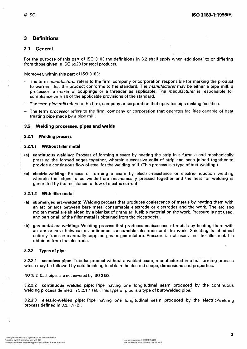
3 Definitions
3.1 General
For the purpose of this part of IS0 3183 the definitions in 3.2 shall apply when additional to or differing from those given in IS0 6929 for steel products.
Moreover, within this part of IS0 3183:
- The term manufacturer refers to the firm, company or corporation responsible for marking the product to warrant that the product conforms to the standard. The manufacturer may be either a pipe mill, a processor, a maker of couplings or a threader as applicable. The manufacturer is responsible for compliance with all of the applicable provisions of the standard.
- The term pipe mill refers to the firm, company or corporation that operates pipe making facilities.
- The term processor refers to the firm, company or corporation that operates facilities capable of heat treating pipe made by a pipe mill.
3.2 Welding processes, pipes and welds
3.2.1 Welding process
3.2.1.1 Without filler metal
(a) continuous welding: Process of forming a seam by heating the strip in a furnace and mechanically pressing the formed edges together, wherein successive coils of strip had been joined together to provide a continuous flow of steel for the welding mill. (This process is a type of butt-welding.)
(b) electric-welding: Process of forming a seam by electric-resistance or electric-induction welding wherein the edges to be welded are mechanically pressed together and the heat for welding is generated by the resistance to flow of electric current.
3.2.1.2 With filler metal
(a) submerged arc-welding: Welding process that produces coalescence of metals by heating them with an arc or arcs between bare metal consumable electrode or electrodes and the work. The arc and molten metal are shielded by a blanket of granular, fusible material on the work. Pressure is not used, and part or all of the filler metal is obtained from the electrode(s).
(b) gas metal arc-welding: Welding process that produces coalescence of metals by heating them with an arc or arcs between a continuous consumable electrode and the work. Shielding is obtained entirely from an externally supplied gas or gas mixture. Pressure is not used, and the filler metal is obtained from the electrode.
3.2.2 Types of pipe
3.2.2.1 seamless pipe: Tubular product without a welded seam, manufactured in a hot forming process which may be followed by cold finishing to obtain the desired shape, dimensions and properties.
NOTE 2 Cast pipes are not covered by IS0 3183.
3.2.2.2 continuous welded pipe: Pipe having one longitudinal seam produced by the continuous welding process defined in 3.2.1.1 (a). (This type of pipe is a type of butt-welded pipe.)
3.2.2.3 electric-welded pipe: Pipe having one longitudinal seam produced by the electric-welding process defined in 3.2.1.1 (b).
3 Copyright International Organization for Standardization Provided by IHS under license with ISO Licensee=Aramco HQ/9980755100
Not for Resale, 04/12/2006 02:18:28 MDTNo reproduction or networking permitted without license from IHS
--``,,`,```````,`````,,,,,,`,`,-`-`,,`,,`,`,,`---
IS0 3183-1:1996(E) 0 IS0
3.2.2.4 longitudinal seam submerged arc-welded pipe: Pipe having one longitudinal seam produced by the automatic submerged arc-welding process defined in 3.2.1.2 (a).
3.2.2.5 gas metal arc-welded pipe: Pipe having one longitudinal or helical seam produced by the continuous gas metal arc-welding process defined in 3.2.1.2 (b).
3.2.2.6 combination gas metal arc- and submerged arc-welded pipe: Pipe having one longitudinal or helical seam produced by a combination of the welding processes defined in 3.2.1.2 (a) and 3.2.1.2 (b)
3.2.2.7 double seam submerged-arc welded pipe: Pipe having two longitudinal seams produced by the automatic submerged-arc welding process defined in 3.2.1.2 (a).
3.2.2.8 double seam gas metal arc-welded pipe: Pipe having two longitudinal seams produced by the gas metal arc-welding process defined in 3.2.1.2 (b).
3.2.2.9 double seam combination gas metal arc- and submerged arc-welded pipe: Pipe having two longitudinal seams produced by a combination of the welding processes defined in 3.2.1.2 (a) and 3.2.1.2 lb).
3.2.2.10 helical seam submerged arc-welded pipe: Pipe having one helical seam produced by the automatic submerged arc-welding process defined in 3.2.1.2 (a). (This type of pipe is also known as spiral weld pipe.)
3.2.3 Types of seam welds
3.2.3.1 electric-weld: Longitudinal seam weld produced by the electric-welding process defined in 3.2.1 .I (b).
3.2.3.2 submerged arc-weld: Longitudinal or helical seam weld produced by the submerged arc-welding process defined in 3.2.1.2 (a).
3.2.3.3 gas metal arc-weld: Longitudinal seam weld produced in whole or in part by the continuous gas metal arc-welding process defined in 3.2.1.2 (b).
3.2.3.4 strip/skelp end weld: Seam weld that joins plate or strip ends together.
3.2.3.5 jointer weld: Circumferential seam weld that joins two pieces of pipe together.
3.2.3.6 tack weld: Seam weld used to align the abutting edges until the final seam welds are produced.
3.2.4 Imperfections and defects
3.2.4.1 An “imperfection” is a discontinuity or irregularity in the product detected by methods outlined in this part of IS0 3183.
3.2.4.2 A “defect” is an imperfection of sufficient magnitude to preclude acceptance of the product in accordance with this part of IS0 3183.
4 Designation
The steels specified in this part of IS0 3183 are designated as shown in table 2 differing from ISO/TR 4949.
NOTE 3 In annex H a comparison of these steel designations with those specified in ANSI/API Spec 5L [II is given.
4
h I* ! 5, I. i
! t,
1 1
Copyright International Organization for Standardization Provided by IHS under license with ISO Licensee=Aramco HQ/9980755100
Not for Resale, 04/12/2006 02:18:28 MDTNo reproduction or networking permitted without license from IHS
--``,,`,```````,`````,,,,,,`,`,-`-`,,`,,`,`,,`---
0 IS0 IS0 3183-1:1996(E)
5 Information to be supplied by the purchaser
In placing orders for line pipe to be manufactured in accordance with this part of IS0 3183 the purchaser should specify the following on the purchase order:
Specification .................................................................................... IS0 3183-1 Quantity ............................................................................................ Grade or class .................................................................................. tables 2 and 3 Type of pipe ..................................................................................... 3.2.2
Size Nominal size
Threaded pipe ....................................................................... table 6 Extra-strong threaded pipe .................................................. table 7 Plain-end pipe ....................................................................... table 8 Extra-strong plain-end pipe ................................................. table 8 Double-extra-strong plain-end pipe .................................... table 8
Outside diameter Regular-mass plain-end pipe . . . . . . . . . . . . . . . . . . . . . . . . . . . . . . . . . . . . . . . . . . . . . . . table 8 Special plain-end pipe . . . . . . . . . . . . . . . . . . . . . . . . . . . . . . . . . . . . . . . . . . . . . . . . . . . . . . . . . . table 8
Mass per metre or wall thickness .................................................. 7.6.1, 7.6.3 Nominal length ................................................................................ 7.6.5 End finish ......................................................................................... 7.6.9 Delivery date and shipping instructions .......................................
The purchaser should also state on the purchase order his requirements concerning the following stipulations, which are optional:
Document of compliance ................................................................................................ Chemical analysis test reports ........................................................................................ Acceptance and maximum allowable length requirements on jointers ..................... Jointers for threaded pipe ............................................................................................... Threaded ends, extra-strong pipe .................................................................................. Alternative bevel, plain-end pipe with outside diameter > 60,3 mm .......................... Special coupling pipe ends ............................................................................................. Power-tight make-up ....................................................................................................... Special non-destructive inspection for laminations ..................................................... Defect repair procedures ................................................................................................. Bare pipe - special coatings ............................................................................................ Method of welding jointers ............................................................................................. Purchaser inspection .......................................................................................................
8.1.1 8.1.2 7.6.7 7.6.7 7.6.9.1 7.6.9.3 7.6.9.5 7.6.9.2 G.3.9 G.6, G.7, G.8 10 annex A annex F
Attention is called to the following stipulations which are subject to agreement between the interested parties:
Strip end welds ................................................................................................... 6.5 Chemical composition ........................................................................................ 7.2.1. Intermediate grades ............................................................................................ 1, 7.2.1, 7.3.2, table B.l Flattening test orientation .................................................................................. 8.5.2.2, figure 3 Intermediate diameters ...................................................................................... 7.6.2 Intermediate wall thickness ............................................................................... 7.6.3 Supplementary requirements ............................................................................ annex D
5 Copyright International Organization for Standardization Provided by IHS under license with ISO Licensee=Aramco HQ/9980755100
Not for Resale, 04/12/2006 02:18:28 MDTNo reproduction or networking permitted without license from IHS
--``,,`,```````,`````,,,,,,`,`,-`-`,,`,,`,`,,`---

IS0 3183-1:1996(E) 0 IS0
NDT electric welds .............................................................................................. 8.9, SR7 NDT seamless pipe ............................................................................................. 8.9, SR2 Supplementary hydrostatic test ......................................................................... 8.10.9.4 Hydrostatic test pressure .................................................................................... 8.10.9.3 Lengths applied to carloads ............................................................................... 7.6.8.6, table 11 Nonstandard length and length tolerances ...................................................... 7.6.5 Welded couplings ............................................................................................... c.1 Thread protectors ................................................................................................ 7.6.9 Repair of welds of electric-welded pipe ............................................................ 8.10.11.3.4, G.5 b) Marking requirements ........................................................................................ 9.2, 9.3, 9.7
This information should preferably be given in the way indicated in the following example.
EXAMPLE
Delivery of 1 500 m regular-mass plain-end pipe of grade L290 with an outside diameter of 457,0 mm, a wall thickness of IO,3 mm and a nominal length of 12 m (see table 111, with document of compliance.
Designation in the order:
1 500 m pipe IS0 3183-1-L290-457,0x10,3x12-with document of compliance.
6 Manufacturing
6.1 Pipe manufacturing
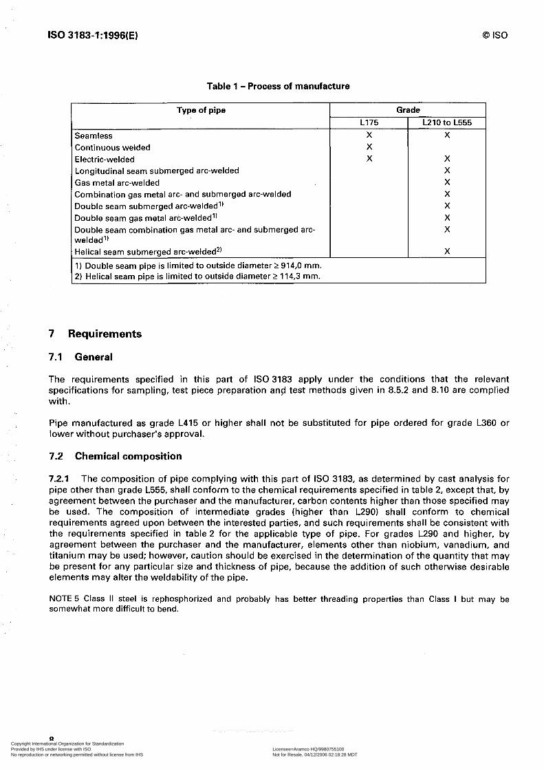
Pipe complying with this part of IS0 3183 shall be subject to the limitations specified in table 1.
6.1.1 Electric-welded pipe in grades higher than L290, the weld seam and the entire heat affected zone shall be heat treated so as to simulate a normalizing heat treatment (see note 41, except that, by agreement between the interested parties, alternative heat treatments or combinations of heat treatment and chemical composition may be substituted. Where such substitutions are made, the manufacturer shall demonstrate the effectiveness of the method selected using a mutually agreed upon procedure, which may include, but is not necessarily limited to, hardness-testing, microstructural evaluation, or mechanical testing. For grades L290 and lower, the weld seam shall be similarly heat treated, or the pipe shall be processed in such a manner that no untempered martensite remains.
NOTE 4 During the manufacture of electric-welded pipe, the product is in motion through the surrounding air. Normalizing is usually defined as “cooling in still air”, hence, the phrase “to stimulate a normalizing heat treatment“ is used.
6.1.2 Longitudinal seam submerged arc-welded pipe, at least one pass shall be on the inside and at least one pass shall be on the outside.
6.1.3 Combination gas metal arc- and submerged arc-welded pipe, the gas metal arc-welding process shall be continuous and first, and followed by the automatic submerged arc-welding process with, at least, one pass on the inside and one pass on the outside.
6.1.4 Double seam submerged arc-welded pipe, the seams shall be approximately 180” apart. For each seam, at least one pass shall be on the inside and at least one pass shall be on the outside.
5, I, t
II I
/ i r ;‘: 5 k
I’
t j,
i i.,
L I-
,’
i
I I
I
j’
/
!” 1’ I
I
I
.-
:
/
i
1,
k
6 Copyright International Organization for Standardization Provided by IHS under license with ISO Licensee=Aramco HQ/9980755100
Not for Resale, 04/12/2006 02:18:28 MDTNo reproduction or networking permitted without license from IHS
--``,,`,```````,`````,,,,,,`,`,-`-`,,`,,`,`,,`---
0 IS0 IS0 3183-1:1996(E)
6.1.5 Double seam gas metal arc-welded pipe, the seams shall be approximately 180” apart. For each seam, at least one pass shall be on the inside and at least one pass shall be on the outside.
6.1.6 Double seam combination gas metal arc- and submerged arc-welded pipe, the seams shall be approximately 180” apart. For each seam, the gas metal arc-welding shall be continuous and first, and followed by the automatic submerged arc-welding process with at least one pass on the inside and one pass on the outside.
6.1.7 Tack welds shall be made by manual or semi-automatic submerged arc-welding; electric-welding; gas metal arc-welding; flux cored arc-welding; or shielded metal arc-welding using low hydrogen electrodes. Tack welds shall be removed by machining or remelted during subsequent welding of the seam.
6.1.8 Helical seam submerged arc-welded pipe, at least one pass shall be on the inside and at least one pass shall be on the outside.
6.2 Cold expansion
Pipe complying with this part of IS0 3183, except continuous welded, shall be either non-expanded or cold expanded at the option of the manufacturer unless otherwise specified on the purchase order. Suitable provision shall be incorporated to protect the weld from contact with the internal expander during mechanical expansion.
6.3 Material
The width of plate or strip used to manufacture helical seam pipe shall be not less than 0,8 or more than 3 times the pipe outside diameter.
6.4 Heat treatment
The heat treating process shall be performed in accordance with a documented procedure. Pipe complying with this part of IS0 3183 may be as rolled, normalized, normalized and tempered, subcritically stress- relieved, or subcritically age-hardened; and grades L290 and higher may be quenched and tempered. (See clause 9 for applicable marking requirements.)
6.5 Strip end welds - helical seam pipe
Junctions of strip end welds and helical seam welds in finished pipe shall be permitted only at distances greater than 304,8 mm from the pipe ends. By agreement between the interested parties, strip end welds shall be permitted at the pipe ends, provided there is a circumferential separation of at least 152,4 mm between the strip end weld and the helical seam weld at the applicable pipe ends. Strip end welds in finished pipe shall be properly prepared for welding and shall be made by automatic submerged arc- welding, automatic gas metal arc-welding, or a combination of such welding procedures.
6.6 Traceability
The manufacturer shall establish and follow procedures for maintaining cast and/or lot identity until all required cast and/or lot tests are performed and conformity with standard requirements has been shown.
7 Copyright International Organization for Standardization Provided by IHS under license with ISO Licensee=Aramco HQ/9980755100
Not for Resale, 04/12/2006 02:18:28 MDTNo reproduction or networking permitted without license from IHS
--``,,`,```````,`````,,,,,,`,`,-`-`,,`,,`,`,,`---
IS0 3183-1:1996(E) 0 IS0
Table 1 - Process of manufacture
Type of pipe
Seamless Continuous welded Electric-welded Longitudinal seam submerged arc-welded Gas metal arc-welded Combination gas metal arc- and submerged arc-welded Double seam submerged arc-welded’) Double seam gas metal arc-welded’) Double seam combination gas metal arc- and submerged arc- welded’) Helical seam submerged arc-welded2) 1) Double seam pipe is limited to outside diameter 2 914,0 mm. 2) Helical seam pipe is limited to outside diameter 2 114,3 mm.
Grade L175 L210 to L555
X X X X X
X X X X X X
X
7 Requirements
7.1 General
The requirements specified in this part of IS0 3183 apply under the conditions that the relevant specifications for sampling, test piece preparation and test methods given in 8.5.2 and 8.10 are complied with.
Pipe manufactured as grade L415 or higher shall not be substituted for pipe ordered for grade L360 or lower without purchaser’s approval.
7.2 Chemical composition
7.2.1 The composition of pipe complying with this part of IS0 3183, as determined by cast analysis for pipe other than grade L555, shall conform to the chemical requirements specified in table 2, except that, by agreement between the purchaser and the manufacturer, carbon contents higher than those specified may be used. The composition of intermediate grades (higher than L290) shall conform to chemical requirements agreed upon between the interested parties, and such requirements shall be consistent with the requirements specified in table 2 for the applicable type of pipe. For grades L290 and higher, by agreement between the purchaser and the manufacturer, elements other than niobium, vanadium, and titanium may be used; however, caution should be exercised in the determination of the quantity that may be present for any particular size and thickness of pipe, because the addition of such otherwise desirable elements may alter the weldability of the pipe.
NOTE 5 Class II steel is rephosphorized and probably has better threading properties than Class I but may be somewhat more difficult to bend.
8 Copyright International Organization for Standardization Provided by IHS under license with ISO Licensee=Aramco HQ/9980755100
Not for Resale, 04/12/2006 02:18:28 MDTNo reproduction or networking permitted without license from IHS
--``,,`,```````,`````,,,,,,`,`,-`-`,,`,,`,`,,`---

0 IS0 IS0 3183-1:1996(E)
Table 2 - Chemical requirements for cast analysisg), % by mass
Type of pipe Grade and class Carbon Manganese Phosphorus Sulfur max.‘) min. max. min. max. max.
seamless Non-expanded or cold expanded L175, Cl I 0,21 0,30 0,60 - 0,030 0,030 Non-expanded or cold expanded L175, Cl 112) 0,21 0,30 0,60 0,045 0,080 0,030 Non-expanded or cold expanded L210 0,22 - 0,90 - 0,030 0,030 Non-expanded or cold expanded L2453’ 0,27 I,15 - 0,030 0,030 Non-expanded L2905’ 0,29 - I,25 - 0,030 0,030 Non-expanded L3205’, L3605) 0,31
0,294’ 1 I,35 - 0,030 0,030
Cold expanded L2905’ L3205) L3605’ L39d5) s), L4; 55’ a
I,25 - 0,030 0,030 Non-expanded or cold expanded 0,26 - I,35 - 0,030 0,030 Non-expanded or cold expanded L450, L485, L555 (By agreement between the interested parties.) Nelded Electric-welded or continous L175, Cl I 0,21 0,30 0,60 - 0,030 0,030 welded only Electric-welded or continous L175, Cl 112) 0,21 0,30 0,60 0,045 0,080 0,030 welded only Non-expanded or cold expanded L210 0,21 0,90 - 0,030 0,030 Non-expanded or cold expanded L245” 0,26 - I,15 - 0,030 0,030 Non-expanded or cold expanded L2905’ 0,28 - I,25 - 0,030 0,030 Non-expanded L3205’, L3605) 0,30 - I,25 - 0,030 0,030 Cold expanded L3205’, L3605) 0,28 - I,25 - 0,030 0,030 Non-expanded or cold expanded L3905) s), L4155) 6, 0,26 - I,35 - 0,030 0,030 Non-expanded or cold expanded L4505’ 7’ 0,26 - I,40 - 0,030 o,o30*’ Non-expanded or cold expanded L4856’ 0,23*) - 1,60*) - 0,030 0,030 Non-expanded or cold expanded L5559’ 0,18*’ g’ 1 808) 9 - I 0,0309’ 0,0309’
1) For grades L290 to L450 for each reduction of 0,Ol % below the specified maximum carbon content, an increase of 0,05 % above the specified maximum manganese content is permissible, up to a maximum of I,45 % for L360 and lower and up to a maximum of I,60 % for grades higher than L360.
2) Class II steel is rephosphorized. (See 7.2.1 for note on bending and threading properties.) 3) Niobium, vanadium, titanium, or combinations thereof, may be used by agreement between the interested
parties. 4) For cold expanded seamless pipe with 2 508 mm outside diameter, the maximum carbon content shall be
0,28 %. 5) Niobium, vanadium, titanium, or combinations thereof, may be used at the discretion of the manufacturer. 5) Other chemical compositions may be furnished by agreement between the interested parties. 7) For grade L450 welded pipe with 2 406,4 mm outside diameter with a wall thickness of 12,7 mm or less, the
chemical composition shall be as shown or as agreed upon between the interested parties; for all other outside diameters and wall thicknesses of such pipe, the chemical composition shall be as agreed upon between the interested parties.
B) For each reduction of 0,Ol % below the specified maximum carbon content, an increase of 0,05 % above the specified maximum manganese content is permissible, up to a maximum of 2,00 %.
9) For grade L555, limits are for product analysis only, thereby eliminating the need for product analysis tolerances in 7.2.2.
9 Copyright International Organization for Standardization Provided by IHS under license with ISO Licensee=Aramco HQ/9980755100
Not for Resale, 04/12/2006 02:18:28 MDTNo reproduction or networking permitted without license from IHS
--``,,`,```````,`````,,,,,,`,`,-`-`,,`,,`,`,,`---
IS0 3183-1:1996(E) 0 IS0
7.2.2 The product analysis shall conform to the chemical requirements shown in table 2, within the following permissible variations for product analysis, except for grade L555 pipe where the requirements in table 2 are for product analysis:
Carbon, %: Seamless pipe
All non-expanded and cold expanded outside diameter c 508 mm . . . . . . . . . . . . . . . . . . . . . . . . . . . . . . . . . . . . . . . . + 0,03 Cold expanded 508 mm outside diameter and larger in grades L290 and higher . . . . . . . . . . . . . . . . . + 0,04
Welded pipe . . . . . . . . . . . . . . . . . . . . ..*.................... . . . . . . . . . . . . . . . . . . . . . . . . . . . . . . . . . . . . . . . . . . . . . . . . . . . . . . . . . . . . . . . . . . . . . . . . . . . . . . . . . . . . . . . . . . . . + 0,04
Manganese, %: All grades up to L240 ......................................................................................................................... + 0,05 Where minimum is specified ............................................................................................................ - 0,05 Grade L290 and higher ...................................................................................................................... + 0,lO Phosphorus, %: .................................................................................................................................. + 0,Ol Where minimum is specified ............................................................................................................ - 0,Ol Sulfur, %: ............................................................................................................................................ + 0,Ol
7.3 Mechanical properties
7.3.1 Acceptance criteria
These shall be in conformity with the requirements of
- tensile test in 8.10.2; - flattening test in 8.10.3; - bend test in 8.10.4; - guided-bend test in 8.10.5; - weld ductility test in 8.10.6; - fracture toughness test in 8.10.7; - hydrostatic test in 8.10.9.
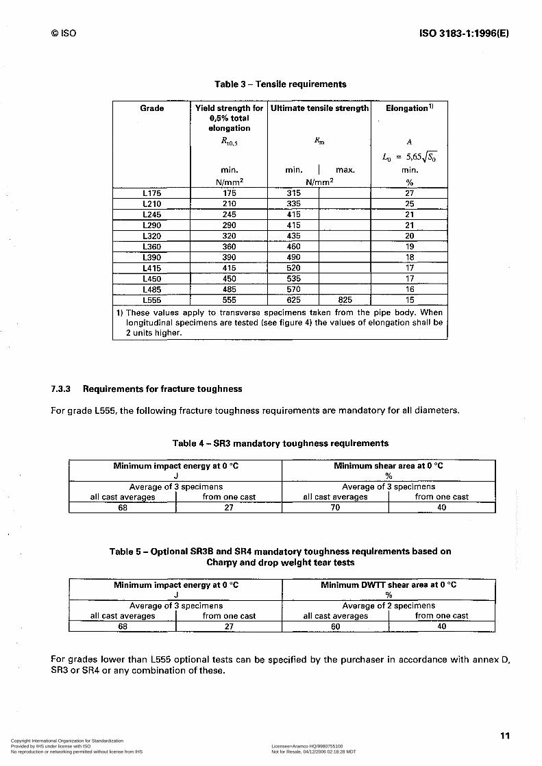
7.3.2 Requirements for tensile strength
Grades L175, L210, L245, L290, L320, L360, L390, L415, L 450, L485 and L555 shall conform to the tensile requirements specified in table 3. Other grades intermediate to the listed grades between L290 and L555 shall conform to tensile requirements agreed upon between the interested parties, which requirements shall be consistent with those specified in table 3. For cold expanded pipe, the ratio of body yield strength and body ultimate tensile strength shall not exceed 0,93. The yield strength shall be the tensile stress required to produce a total elongation of 0,5 % of the gauge length as determined by an extensometer.
1 I I 1 / I i s ;: i 1 h i 1 j 1; I\ 1 1:. ;, [ i 1; I 1 1: I E / t
!, I / I
/ k I i ! I,
10 Copyright International Organization for Standardization Provided by IHS under license with ISO Licensee=Aramco HQ/9980755100
Not for Resale, 04/12/2006 02:18:28 MDTNo reproduction or networking permitted without license from IHS
--``,,`,```````,`````,,,,,,`,`,-`-`,,`,,`,`,,`---
0 IS0 IS0 3183-1:1996(E)
Table 3 - Tensile requirements
1) These values apply to transverse specimens taken from the pipe body. When longitudinal specimens are tested (see figure 4) the values of elongation shall be 2 units higher.
7.3.3 Requirements for fracture toughness
For grade L555, the following fracture toughness requirements are mandatory for all diameters.
Table 4 - SR3 mandatory toughness requirements
Minimum impact energy at 0 “C Minimum shear area at 0 “C J %
Average of 3 specimens Average of 3 specimens all cast averages from one cast all cast averages from one cast
68 27 70 40
Table 5 - Optional SR3B and SR4 mandatory toughness requirements based on Charpy and drop weight tear tests
Minimum impact energy at 0 “C Minimum DVVlT shear area at 0 “C I J
Average of 3 specimens all cast averages I from one cast
68 27
% Average of 2 specimens
all cast averages from one cast 60 I 40
For grades lower than L555 optional tests can be specified by the purchaser in accordance with annex D, SR3 or SR4 or any combination of these.
11 Copyright International Organization for Standardization Provided by IHS under license with ISO Licensee=Aramco HQ/9980755100
Not for Resale, 04/12/2006 02:18:28 MDTNo reproduction or networking permitted without license from IHS
--``,,`,```````,`````,,,,,,`,`,-`-`,,`,,`,`,,`---
IS0 3183-1:1996(E) 0 IS0
7.4 Metallurgical requirement
For grades higher than L290, full body normalized pipe excluded, compliance with the requirement of 6.1.1 that the entire heat affected zone be heat treated shall be demonstrated by metallographic examinations of a weld cross-section.
7.5 Appearance, imperfections and defects
7.51 For workmanship, visual inspection and repair of defects annex G applies.
7.5.2 For the acceptance limits for non-destructive inspection 8.10.11 applies.
7.6 Dimensions, masses and tolerances
7.6.1 General-Dimensions and masses: Line pipe shall be made in the outside diameters, wall thicknesses, and masses provided in tables 6, 7, 8 and 9 and in 7.6.2 and 7.6.3, respectively or in the relevant dimensions and masses given in IS0 4200, as specified on the purchase order.
The plain-end mass M shall be calculated using the following formula:
M= (D-T)xTx0,024 6615
where
M is the mass per unit length, in kilograms per metre, rounded to the nearest 0,Ol kg/m; D is the outside diameter, in millimetres, rounded to the nearest 0,l mm for sizes < 457,0 mm,
and 1 mm for sizes 2 457,0 mm; T is the specified wall thickness, in millimetres, rounded to the nearest 0,l mm.
The coefficient takes into account a density equal to 7,85 kg/dm3.
7.6.2 Diameter
The outside diameter shall be within the tolerances specified in 7.6.8.1 (inside diameters are governed by the outside diameter and mass tolerances). Pipe in grades L290 and higher with outside diameters intermediate to those listed in table 9 is available in outside diameters 2 508,O mm by agreement between the interested parties. Such pipe shall be consistent with all requirements of this part of IS0 3183 and shall be marked with the specified outside diameter. For threaded pipe, the outside diameter at the threaded ends shall be such that the thread length L4 and the number of full-crest threads in that length are within the dimensions and tolerances specified in IS0 10422 (inside diameters are governed by the outside diameter and mass tolerances).
7.6.3 Wall thickness
The wall thickness at any place shall be within the tolerances specified in 7.6.8.4 except that the weld area shall not be limited by the plus tolerance.
Pipe with wall thicknesses intermediate to those listed in tables 8 and 9 is available by agreement between the interested parties. Such pipe shall be consistent with all requirements of this part of IS0 3183 and shall be marked in accordance with clause 9 using the specified wall thickness to calculate M .
/ I 1 1 / t 1 s
/ I, [ I I, i, 1 1 1, I
I I E I 1 ! I
8’
12 Copyright International Organization for Standardization Provided by IHS under license with ISO Licensee=Aramco HQ/9980755100
Not for Resale, 04/12/2006 02:18:28 MDTNo reproduction or networking permitted without license from IHS
--``,,`,```````,`````,,,,,,`,`,-`-`,,`,,`,`,,`---

0 IS0 IS0 3183-1:1996(E)
7.6.4 Mass
The masses determined as described in 8.10.10.3 shall conform to the specified masses or calculated masses for plain-end pipe, or to the specified calculated masses (or adjusted calculated masses) for threaded-and-coupled pipe, within the tolerances specified in 7.6.8.5.
Calculated masses shall be determined in accordance with the following formula:
M, = (MXL) + c&j
where
M, is the calculated mass of a pipe of length L, in kilograms; M is the plain-end mass per unit length, in kilograms per metre; L is the length of pipe, including end finish, as defined in 7.6.5 and 8.10.10.4, in metres; eM is the mass gain or loss due to end finishing, in kilograms.
For plain-end pipe, eM equals zero.
7.6.5 Length
Unless otherwise agreed upon between the interested parties, pipe shall be made in the nominal lengths and within the length tolerances shown in table 11, as specified on the purchase order.
7.6.6 Straightness
Pipe in grades L175, L210 and L245 of an outside diameter less than 114,3 mm shall be reasonably straight. For all other pipe the deviation from a straight line shall not exceed 0,2 percent of the length.
7.6.7 Jointers
When specified on the purchase order, jointers (two lengths of pipe coupled together by the manufacturer, or two lengths of pipe welded together by the manufacturer in accordance with the requirements of annex A or other equivalent method as agreed between the interested parties), may be provided; however, no length used in making a jointer shall be shorter than 1 520 mm.
Double joints are not within the purview of this part of IS0 3183. Double joints are defined as two or more lengths of pipe welded together by parties other than the manufacturer, or two or more lengths welded together by the manufacturer in accordance with requirements other than those of annex A.
13 Copyright International Organization for Standardization Provided by IHS under license with ISO Licensee=Aramco HQ/9980755100
Not for Resale, 04/12/2006 02:18:28 MDTNo reproduction or networking permitted without license from IHS
--``,,`,```````,`````,,,,,,`,`,-`-`,,`,,`,`,,`---

IS0 3183-1:1996(E) 0 IS0
Table 6 - Threaded line pipe dimensions, masses and test pressures
I) Nominal masses, threads and coupling are shown for the purpose of identification in ordering. 2) Mass gain due to end finishing. See 7.6.4. 3) The test pressures have been calculated on the basis of the formula in 8.10.9.3 for standard test pressure except
those for grades L175 (all values) and L210/L245 (up to nominal size 2) which were established arbitrarily. 4) 100 kPa = 1 bar.
Trianglestamp keenote) -D
Basic power-tight make-up Hand-tight make-up
(See table 6 for pipe dimensions, table C.l for coupling dimensions and IS0 10422 for thread details.)
1 , I
I
I
i
i
j
I
i
k
1
[
1
;
i:
t f i
r
1 i,
i
;
1
!:
I I i //
I
I
,’ i
/
i
i 8.
j
i
i
Figure 1 - Line pipe and coupling
14 Copyright International Organization for Standardization Provided by IHS under license with ISO Licensee=Aramco HQ/9980755100
Not for Resale, 04/12/2006 02:18:28 MDTNo reproduction or networking permitted without license from IHS
--``,,`,```````,`````,,,,,,`,`,-`-`,,`,,`,`,,`---

0 IS0 IS0 3183-1:1996(E)
Table 7 - Extra-strong threaded line pipe dimensions, masses and test pressures
Nominal size designation
118 l/4 318 I/2 314 1
1 II4 1 l/2 2 2 l/2 3 3 l/2 4 5 6 8 10 12
Uominal mass designation, threads and
coupling’)
0.54 0.74
0,31
I,09 I,48 2,18 3,02 3,66 5,07 7.73
10133 12,63 15,17 21,09 28,89 43,90 55,82 66,7 1
Outside diameter
D mm IO,3 13,7 17,l 21,3 26,7 33,4 42,2 48,3 60,3 73.0 88,9
101,6 114,3 141,3 168,3 219,l 273,0 323,8
T-
'1 Wall
thickness
T mm 2,4 3.0 312 3,7 33 4,5 43 5,l 5,5 7.0 7;6 8.1 816 93
II,0 12,7 12,7 12,7
Minimum test pressure2)
Grade
L175 1 L210 1 L245
100 kPa3)
1) Nominal masses, threads and coupling are shown for the purpose of identification in ordering.
2) Test pressures established arbitrarily. For grades L210 and L245 (nominal size 2 2Y2) the values have been calculated on the basis of the formula in 8.10.9.3 for standard test pressure.
3) 100 kPa = 1 bar.
15 Copyright International Organization for Standardization Provided by IHS under license with ISO Licensee=Aramco HQ/9980755100
Not for Resale, 04/12/2006 02:18:28 MDTNo reproduction or networking permitted without license from IHS
--``,,`,```````,`````,,,,,,`,`,-`-`,,`,,`,`,,`---

IS0 3183-1:1996(E) 0 IS0
Table 8 - Plain-end line pipe dimensions’), masses and test pressures2)
L175 1 L210 1 L245
1) Outside diameter and wall thickness dimensions shown are subject to tolerances as described in 7.6.8. Inside diameters are nominal and are given here for information (see 7.6.2).
2) Test pressures apply to the standard grades. For pressures applicable for other grades see 8.10.9.3. 3) Test pressures established arbitrarily. 4) 100 kPa = 1 bar.
16 Copyright International Organization for Standardization Provided by IHS under license with ISO Licensee=Aramco HQ/9980755100
Not for Resale, 04/12/2006 02:18:28 MDTNo reproduction or networking permitted without license from IHS
--``,,`,```````,`````,,,,,,`,`,-`-`,,`,,`,`,,`---

Table 9 - Plain-end line pipe dimensionsl), masses and test pressures2) (to be ordered according to outside diameter)
2 718 13,69 73,0 14,0 45,0 96 172 172 207 207 207 207 207 207 207 207 3 l/23’ 3,03 88,9 ZJ 84,7 41 60 69 82x 91x 102x 111x 118x 128x 137x 157x 3 I/23’ 3,95 88,9 2.8 83,3 55 79 93 110x 121x 136x 147x 157x 170x 183x 207
I) Outside diameter and wall thickness dimensions shown are subject to tolerances as described in 7.6.8. Inside diameters are nominal and are given here for information (see 7.6.2).
2) Test pressures apply to the standard grades. For pressures applicable for other grades see 8.10.9.3. 3) These sizes are special plain-end mass sizes. All other sizes are regular-mass, see 7.6.8 for applicable mass tolerances. For grades L 290 and higher masses intermediate
to regular-masses shall be considered regular-mass; masses intermediate to special-plain-end masses and masses intermediate between the heaviest tabulated special- plain-end masses and the highest regular-masses shall be considered special-plain-end mass.
4) The test pressures have been calculated on the basis of the formula in 8.10.9.3 as standard test pressure considering specified maximum values (see table 15). Sizes for which an alternative test pressure (1,25x standard test pressure, rounded to the next higher 100 kPA with maximum values to be considered) may be requested are marked by ‘x” after the standard test pressure. L175 values were established arbitrarily.
5) 100 kPA = 1 bar
Copyright International Organization for Standardization Provided by IHS under license with ISO Licensee=Aramco HQ/9980755100
Not for Resale, 04/12/2006 02:18:28 MDTNo reproduction or networking permitted without license from IHS
--``,,`,```````,`````,,,,,,`,`,-`-`,,`,,`,`,,`---
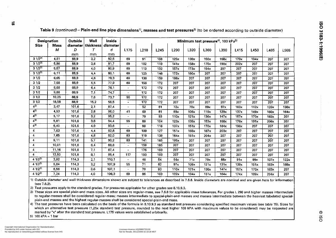
Table 9 (continuedl- Plain-end line pipe dimensions’), masses and test pressures*’ (to be ordered according to outside diameter)
Designation Outside Wall Inside Minimum test pressure4), 100 kPa5) Size Mass diameter thickness diameter
M D T d L175 1 L210 1 L245 1 L290 1 L320 ( L360 1 L390 1 L415 1 L450 1 L485
207 207 207 207 138x j
207 1
1) Outside diameter and wall thickness dimensions shown are subject to tolerances as described in 7.6.8. Inside diameters are nominal and are given here for information (see 7.6.2).
~ 2) Test pressures apply to the standard grades. For pressures applicable for other grades see 8.10.9.3. 3) These sizes are special plain-end mass sizes. All other sizes are regular-mass, see 7.6.8 for applicable mass tolerances. For grades L 290 and higher masses intermediate
to regular-masses shall be considered regular-mass; masses intermediate to special-plain-end masses and masses intermediate between the heaviest tabulated special- plain-end masses and the highest regular-masses shall be considered special-plain-end mass.
4) The test pressures have been calculated on the basis of the formula in 8.10.9.3 as standard test pressure considering specified maximum values (see table 15). Sizes for which an alternative test pressure (1,25x standard test pressure, rounded to the next higher 100 kPA with maximum values to be considered) may be requested are marked by .x. after the standard test pressure. L175 values were established arbitrarily.
5) lOOkPA=l bar
Copyright International Organization for Standardization Provided by IHS under license with ISO Licensee=Aramco HQ/9980755100
Not for Resale, 04/12/2006 02:18:28 MDTNo reproduction or networking permitted without license from IHS
--``,,`,```````,`````,,,,,,`,`,-`-`,,`,,`,`,,`---
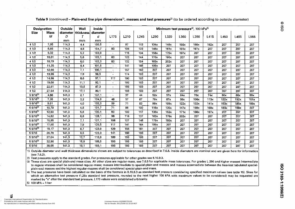
Table 9 (continued) - Plain-end line pipe dimensions’), masses and test pressure$ (to be ordered according to outside diameter)
Designation Outside Wall Inside Minimum test pressure4), 100 I Size Mass diameter thickness diameter
M D T d L175 / L210 1 L245 / L290 j L320 / L360 1 L390
I ( m m 1 m m 1 m m 1 I 4 l/2 1 7,95 1 114,3 1 4.4 1 105,5 1 - 1 97 1 113 1 134x 1 148x 1 166x 1 180x
1
4 l/2 1 8.66 1 114.3 t 4.8 1 104.7 1 83 1 106 1 123 1 146x 1 161x 1 181x 1 197x 4 l/2 9,32 114,3 52 103.9 - 115 134 158x 175x 197x 207 4 l/2 IO,01 114,3 5.6 103,l 83 123 144 170x 190x 207 207 4 l/2 1 10.79 I 114,3 I 6,0 I 102,3 I 83 I 132 I 154 I 183x j 202x j 207 j 207 4 l/2 1 11.35 1 114.3 i 6.4 I 101.5 I - 1 141 1 165 1 195x j 207 j 207 j 207 4 l/2 12,66 114.3 7,l 100,l - 157 183 207 207 207 207 4 l/2 13.96 114,3 73 98.5 - 174 193 207 207 207 207 4 l/2 14,98 114,3 8,6 97,1 117 190 193 207 207 207 207 4 l/2 19,oo 114,3 II,1 92,1 - 193 193 207 207 207 207 4 l/2 22,51 114,3 13,5 87,3 - 193 193 207 207 207 207 4 l/2 27,54 114,3 17,l 80,l 193 193 207 207 207 207 5 9/l 63’ 4,86 141,3 z1 137,l - 37 44 52x 57x 64x 70x
1 5 9/l63’ 1 7,26 1 141.3 1 3.2 1 134.9 1 48 1 57 1 67 1 79x 1 87x 1 98x 1 106x 5 9/l 63’ 9,Ol 141.3 4,O 133.3 59 71 83 99x 109x 122x 132x 5 9/l 63’ IO,79 141,3 48 131,7 71 96 100 118x 130x 147x 159x 5 9/l 63’ 12,50 141,3 56 130,l 83 100 117 138x 152x 171x 186x 5 9/l63’ 14.62 141.3 6.6 128,l 98 118 137 163x 179x 202x 207 5 9/l 63’ 15,85 141,3 7,l 127,l 108 127 148 175x 193x 207 207 5 9/l 63’ 17,50 141,3 7,9 125,5 117 141 164 195x 207 207 207 5 9/I 63’ 19.17 141,3 8,7 123,9 129 155 181 207 207 207 207 5 9116 20,78 141,3 93 122,3 141 169 193 207 207 207 207 5 9/l 63’ 27.04 141.3 12.7 115.9 189 193 193 207 207 207 207 5 9/l 63’ 32,96 141,3 15.9 109,5 193 193 193 207 207 207 207 5 9116 38,55 141,3 19.1 103,l 193 193 193 207 207 207 207
113x 1 122x 1 132x 1 151x 1 141x 153x 185x 189x 169x 183x 198x 207 197x 1 207 1 207 1 207 207 1 207 1 207 1 207
207 1 207 1 207 1 207 1
1) Outside diameter and wall thickness dimensions shown are subject to tolerances as described in 7.6.8. Inside diameters are nominal and are given here for informatior (see 7.6.2).
2) Test pressures apply to the standard grades. For pressures applicable for other grades see 8.10.9.3. 3) These sizes are special plain-end mass sizes. All other sizes are regular-mass, see 7.6.8 for applicable mass tolerances. For grades L 290 and higher masses intermediate
to regular-masses shall be considered regular-mass; masses intermediate to special-plain-end masses and masses intermediate between the heaviest tabulated special. plain-end masses and the highest regular-masses shall be considered special-plain-end mass.
4) The test pressures have been calculated on the basis of the formula in 8.10.9.3 as standard test pressure considering specified maximum values (see table 15). Sizes for which an alternative test pressure (1,25x standard test pressure, rounded to the next higher 100 kPA with maximum values to be considered) may be requested are marked by .x” after the standard test pressure. L175 values were established arbitrarily.
5) 100 kPA= 1 bar
Copyright International Organization for Standardization Provided by IHS under license with ISO Licensee=Aramco HQ/9980755100
Not for Resale, 04/12/2006 02:18:28 MDTNo reproduction or networking permitted without license from IHS
--``,,`,```````,`````,,,,,,`,`,-`-`,,`,,`,`,,`---

Table 9 (continued) - Plain-end line pipe dimensions’), masses and test pressures*) (to be ordered according to outside diameter)
Designation Outside Wall inside Minimum test pressure4), 100 kPa5) Size Mass diameter thickness diameter
M D T d L2106’ L245’j) L290 L320 L360 L390 L415 L450 L485 L555 m m m m m m
6 5/83’ 5,80 168,3 z1 164,l 31 37 54 60 67 73 78 84 91 103 6 5/83’ 7,59 168,3 23 162,7 42 49 72 80 90 97 104 112 121 137 6 5/83’ 8,88 168,3 32 161,9 48 56 83 91 103 111 118 128 138 157 6 5/83’ 9,76 168,3 33 161,l 54 63 93 103 116 125 133 144 156 176 6 5/83’ IO,78 168.3 4,O 160,3 60 70 103 114 128 139 148 160 173 196 6 518 II,85 168.3 4,4 159,5 66 77 114 125 141 153 163 176 190 207 6 518 12,92 168,3 48 158,7 72 84 124 137 154 167 178 193 207 207 6 518 13,92 168,3 52 157,9 78 91 134 148 167 181 192 207 207 207 6 518 14,98 168,3 56 157,l 84 98 145 160 180 195 207 207 207 207 6 518 17,02 168,3 64 155,5 96 112 165 183 205 207 207 207 207 207 6 518 18,97 168,3 7.1 154,l 106 124 184 202 207 207 207 207 207 207 6 518 21,04 168,3 789 152,5 118 138 204 207 207 207 207 207 207 207 6 518 23,08 168,3 887 150,9 130 152 207 207 207 207 207 207 207 207 6 518 25,03 168,3 93 149.3 142 166 207 207 207 207 207 207 207 207 6 518 28,57 168,3 II,0 146,3 165 192 207 207 207 207 207 207 207 207 6 518 32,7 1 168,3 12,7 142,9 190 193 207 207 207 207 207 207 207 207 6 518 38,39 168,3 14,3 139,7 193 193 207 207 207 207 207 207 207 207 6 518 40,05 168,3 15,9 136,5 193 193 207 207 207 207 207 207 207 207 6 518 45,35 168,3 18,3 131,7 193 193 207 207 207 207 207 207 207 207 6 518 47,06 168,3 19,l 130,l 193 193 207 207 207 207 207 207 207 207 6 518 53,73 168,3 22,2 123,9 193 193 207 207 207 207 207 207 207 207
; g:i II,35 14,ll 219,l 219,l 32 4,O 212.7 211.1 37 46 54 43 79 64 70 88 79 99 107 85 114 91 123 99 106 133 120 151 8 518 16,94 219,l 4,8 209,5 55 64 95 105 118 128 136 148 159 181 8 518 18,26 219,l 52 208,7 60 70 103 114 128 139 148 160 173 196 8 518 19,66 219.1 56 207,9 64 75 111 123 138 150 159 173 186 207 8 518 22,36 219,l 64 206,3 74 86 127 140 158 171 182 197 207 207 8 518 24,70 219,l 7,O 205,l 81 94 139 153 173 187 199 207 207 207 8 518 27,70 219,l 73 203,3 91 106 157 173 195 207 207 207 207 207 8 518 28,55 219,l 82 202.7 94 110 163 180 202 207 207 207 207 207 8 518 30,42 219,l 8,7 201,7 100 117 173 191 207 207 207 207 207 207
1) Outside diameter and wall thickness dimensions shown are subject to tolerances as described in 7.6.8. Inside diameters are nominal and are given here for information (see 7.6.2).
2) Test pressures apply to the standard grades. For pressures applicable for other grades see 8.10.9.3. 3) These sizes are special plain-end mass sizes. All other sizes are regular-mass, see 7.6.8 for applicable mass tolerances. For grades L 290 and higher masses
intermediate to regular-masses shall be considered regular-mass; masses intermediate to special-plain-end masses and masses intermediate between the heaviest tabulated special-plain-end masses and the highest regular-masses shall be considered special-plain-end mass.
4) The test pressures have been calculated on the basis of the formula in 8.10.9.3 as standard test pressure considering specified maximum values (see table 15). 5) 100 kPA = 1 bar 6) An alternative test pressure (1,25x standard test pressure, rounded to the next higher 100 kPA with a maximum value of 19 300 kPa to be considered) may be
requested.
/(__r-_..7-_-_ -. ._ ,. .~ .~ - .-. ~-~ ~. ..~ ~._. I -,-l-r-_?-/-i-v>T-7 ___=.~ .~ --_--._ -.- .-- I_--
Copyright International Organization for Standardization Provided by IHS under license with ISO Licensee=Aramco HQ/9980755100
Not for Resale, 04/12/2006 02:18:28 MDTNo reproduction or networking permitted without license from IHS
--``,,`,```````,`````,,,,,,`,`,-`-`,,`,,`,`,,`---
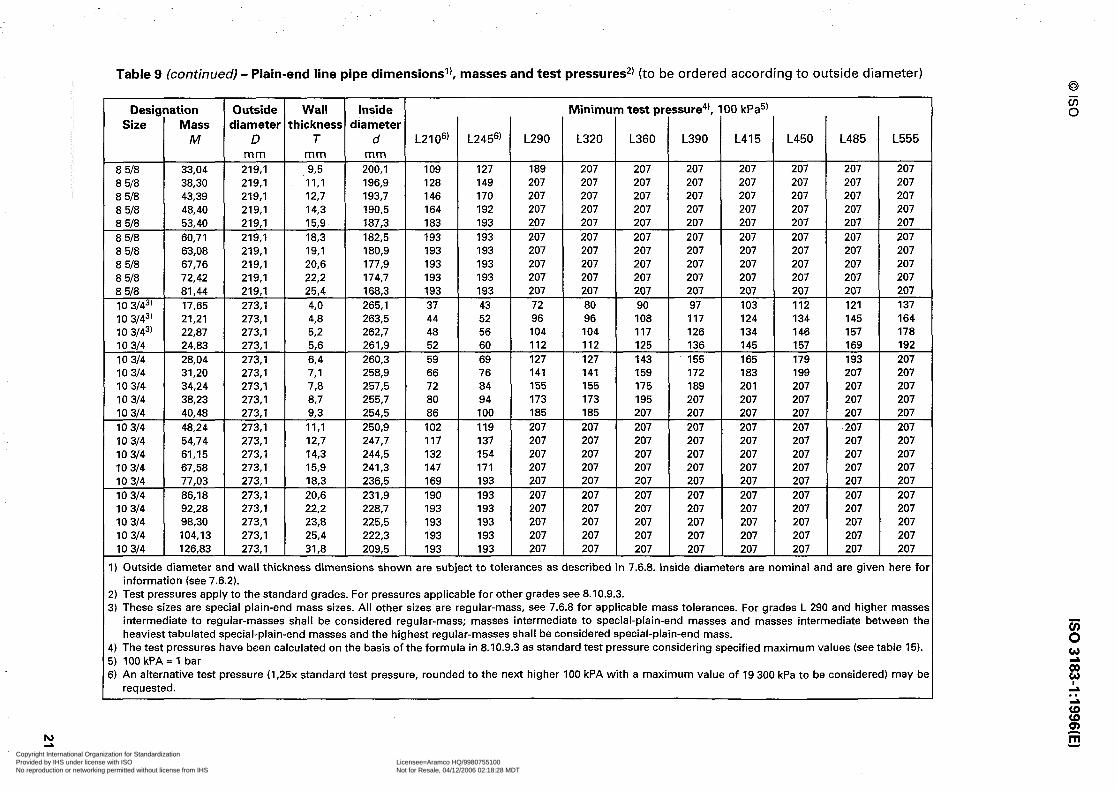
Table 9 (continued) - Plain-end line pipe dimensions’), masses and test pressures*’ (to be ordered according to outside diameter)
Designation Outside Wall Inside Minimum test pressure4), 100 kPa5) Size Mass diameter thickness diameter
M D T d L2 1 06) L2456’ L290 L320 L360 L390 L415 L450 L485 L555 mm mm mm
8 518 33,04 219,l 93 200,l 109 127 189 207 207 207 207 207 207 207 8 518 38,30 219,l II,1 196,9 128 149 207 207 207 207 207 207 207 207 8 518 43,39 219,l 12,7 193,7 146 170 207 207 207 207 207 207 207 207 8 518 48,40 219,l 14,3 190,5 164 192 207 207 207 207 207 207 207 207 8 618 53,40 219,l 15,9 187,3 183 193 207 207 207 207 207 207 207 207 8 518 60,71 219,l 18,3 182,5 193 193 207 207 207 207 207 207 207 207 8 518 63,08 219,l 19,l 180,9 193 193 207 207 207 207 207 207 207 207 8 518 67,76 219,l 20,6 177,9 193 193 207 207 207 207 207 207 207 207 8 518 72,42 219,l 22,2 174,7 193 193 207 207 207 207 207 207 207 207 8 518 81,44 219,l 25,4 168,3 193 193 207 207 207 207 207 207 207 207 10 3143' 17,65 273,l 4,O 265,l 37 43 72 80 90 97 103 112 121 137 10 3143' 21,21 273,l 48 263,5 44 52 96 96 108 117 124 134 145 164 10 3143' 22,87 273,l 5.2 262,7 48 56 104 104 117 126 134 146 157 178 10 314 24,83 273,l 56 261,9 52 60 112 112 125 136 145 157 169 192 10 314 28,04 273,l 64 260,3 59 69 127 127 143 155 165 179 193 207 10 314 31,20 273,l 7,l 258,9 66 76 141 141 159 172 183 199 207 207 10 314 34,24 273,l 73 257,5 72 84 155 155 175 189 201 207 207 207 10 314 38,23 273,l 87 255,7 80 94 173 173 195 207 207 207 207 207 10 314 40,48 273,l 93 254,5 86 100 185 185 207 207 207 207 207 207 10 314 48,24 273,l II,1 250,9 102 119 207 207 207 207 207 207 207 207 10 314 54,74 273,l 12,7 247,7 117 137 207 207 207 207 207 207 207 207 10 314 61,15 273,l 14,3 244,5 132 154 207 207 207 207 207 207 207 207 10 314 67,58 273,l 15,9 241,3 147 171 207 207 207 207 207 207 207 207 10 314 77,03 273,l 18,3 236,5 169 193 207 207 207 207 207 207 207 207 10 314 86,18 273.1 20,6 231,9 190 193 207 207 207 207 207 207 207 207 10 314 92.28 273,l 22,2 228,7 193 193 207 207 207 207 207 207 207 207 10 314 98,30 273,l 23,8 225,5 193 193 207 207 207 207 207 207 207 207 10 314 104,13 273,l 25,4 222,3 193 193 207 207 207 207 207 207 207 207 10 314 126.83 273,l 31.8 209,5 193 193 207 207 207 207 207 207 207 207
1) Outside diameter and wall thickness dimensions shown are subject to tolerances as described in 7.6.8. Inside diameters are nominal and are given here fo information (see 7.6.2).
2) Test pressures apply to the standard grades. For pressures applicable for other grades see 8.10.9.3. 3) These sizes are special plain-end mass sizes. All other sizes are regular-mass, see 7.6.8 for applicable mass tolerances. For grades L 290 and higher masse
intermediate to regular-masses shall be considered regular-mass; masses intermediate to special-plain-end masses and masses intermediate between thj heaviest tabulated special-plain-end masses and the highest regular-masses shall be considered special-plain-end mass.
4) The test pressures have been calculated on the basis of the formula in 8.10.9.3 as standard test pressure considering specified maximum values (see table 15). 5) 100 kPA = 1 bar 5) An alternative test pressure (1,25x standard test pressure, rounded to the next higher 100 kPA with a maximum value of 19 300 kPa to be considered) may bi
requested.
Copyright International Organization for Standardization Provided by IHS under license with ISO Licensee=Aramco HQ/9980755100
Not for Resale, 04/12/2006 02:18:28 MDTNo reproduction or networking permitted without license from IHS
--``,,`,```````,`````,,,,,,`,`,-`-`,,`,,`,`,,`---

Table 9 (continued) - Plain-end line pipe dimensionsl), masses and test pressures2) (to be ordered according to outside diameter)
Designation Outside Wall Inside Minimum test pressure4), 100 kPa5) Size Mass diameter thickness diameter
M D T d L21 06’ L245’j’ L290 L320 L360 L390 L415 L450 L485 L555 mm mm mm
12 3143’ 23,ll 323,9 4,4 315,l 34 40 59 65 73 79 85 92 99 112 12 3143’ 25.22 323,9 4.8 314,3 37 44 64 71 80 87 92 100 108 122 12 3143’ 27,20 323,9 52 313,5 40 47 70 77 87 94 100 108 117 132 12 3143’ 29,31 323.9 56 312,7 44 51 75 83 93 101 108 117 126 143 12 3143’ 33,38 323,9 64 311,l 50 58 86 95 107 116 123 133 144 163 12 314 37,42 323,9 7,l 309,7 55 64 95 105 118 128 136 148 159 181 12 314 41,45 323,9 73 308,l 61 72 106 117 132 143 152 165 177 201 12 314 43,77 323,9 8A 307,l 65 76 113 124 140 152 161 175 189 207 12 314 45‘58 323‘9 8.7 306,5 68 79 117 129 145 157 167 181 195 207 12 314 49.56 323,9 92 304,9 74 86 128 141 158 172 183 198 207 207 12 314 53,52 323.9 IO,3 303,3 80 93 138 153 172 186 198 207 207 207 12 314 57,59 323.9 11,l 301,7 86 101 149 164 185 200 207 207 207 207 12 314 65,42 323.9 12,7 298,5 99 115 171 188 207 207 207 207 207 207 12 314 73,15 323,9 14,3 295,3 111 130 192 207 207 207 207 207 207 207 12 314 80,93 323,9 15,9 292,l 124 144 207 207 207 207 207 207 207 207 12 314 88.63 323,9 17,5 288,9 136 159 207 207 207 207 207 207 207 207 12 314 96.12 323,9 19,l 285,7 149 173 207 207 207 207 207 207 207 207 12 314 103,53 323,9 20.6 282,7 160 187 207 207 207 207 207 207 207 207 12 314 1 IO,97 323,9 22,2 279,5 173 193 207 207 207 207 207 207 207 207 12 314 118,33 323.9 23.8 276,3 185 193 207 207 207 207 207 207 207 207 12 314 125,49 323.9 25.4 273,l 193 193 207 207 207 207 207 207 207 207 12 314 132,57 323.9 27,0 269.9 193 193 207 207 207 207 207 207 207 207 12 314 139,67 323,9 28.6 266,7 193 193 207 207 207 207 207 207 207 207 12 314 153,53 323,9 31,8 260,3 193 193 207 207 207 207 207 207 207 207 143’ 27.73 355,6 48 346,0 34 40 67 73 83 89 95 103 111 126 143’ 29,91 355,6 52 345,2 37 43 72 80 89 97 103 112 121 137 143) 30.93 355,6 5,3 345,0 38 44 73 81 91 99 105 114 123 139 143’ 32.23 355,6 56 344,4 40 46 78 86 96 104 111 120 130 147 143’ 36,71 355,6 64 342,8 45 53 89 98 110 119 127 138 148 168
I) Outside diameter and wall thickness dimensions shown are subject to tolerances as described in 7.6.8. Inside diameters are nominal and are given here for information (see 7.6.2).
?) Test pressures apply to the standard grades. For pressures applicable for other grades see 8.10.9.3. 3) These sizes are special plain-end mass sizes. All other sizes are regular-mass, see 7.6.8 for applicable mass tolerances. For grades L 290 and higher masse:
intermediate to regular-masses shall be considered regular-mass; masses intermediate to special-plain-end masses and masses intermediate between thr heaviest tabulated special-plain-end masses and the highest regular-masses shall be considered special-plain-end mass.
I) The test pressures have been calculated on the basis of the formula in 8.10.9.3 as standard test pressure considering specified maximum values (see table 15). 5) 100 kPA = 1 bar 3) An alternative test pressure (1,25x standard test pressure, rounded to the next higher 100 kPA with a maximum value of 19 300 kPa to be considered) may br
requested.
-~--yi-.+----~- - .- - _: . , . . , -- I . _..l._j,. ~_ .~~_ _ . . .__ ._ . -‘- ---.-------_i-.c”--~--- ij__ ..-.__= ____? .*_____l_ _ _____ _ ____
Copyright International Organization for Standardization Provided by IHS under license with ISO Licensee=Aramco HQ/9980755100
Not for Resale, 04/12/2006 02:18:28 MDTNo reproduction or networking permitted without license from IHS
--``,,`,```````,`````,,,,,,`,`,-`-`,,`,,`,`,,`---

Table 9 fcontinued) - Plain-end line pipe dimensions’), masses and test pressures2) (to be ordered according to outside diameter)
Designation Outside Wall Inside Minimum test pressure4), 100 kPa5) Size Mass diameter thickness diameter
M D T d L2106’ L2456’ L290 L320 L360 L390 L415 L450 L485 L555 m m m m m m
14 41,17 355,6 7,1 341,4 50 59 98 109 122 132 141 153 165 187 14 45,61 355,6 789 339,8 56 65 110 121 136 147 157 170 183 207 14 50,17 355,6 8,7 338,2 62 72 121 133 150 ‘I62 173 187 202 207 14 54,57 355,6 985 226,6 67 79 132 145 163 177 188 204 207 207 14 58,94 3556 IO,3 335,0 73 85 143 158 177 192 204 207 207 207 14 63,44 355,6 II,1 333,4 79 92 154 170 191 207 207 207 207 207 14 67,78 355,6 11,9 331.8 84 98 165 182 205 207 207 207 207 207 14 72,09 355,6 12,7 330,2 90 105 176 194 207 207 207 207 207 207 14 80.66 355,6 14,3 327.0 101 118 198 207 207 207 207 207 207 207 14 89,28 355,6 15,9 323.8 113 131 207 207 207 207 207 207 207 207 14 97,81 355,6 17,5 320,6 124 145 207 207 207 207 207 207 207 207 14 106,13 355,6 19,l 317,4 135 158 207 207 207 207 207 207 207 207 14 114,37 355,6 20,6 314,4 146 170 207 207 207 207 207 207 207 207 14 122,65 355,6 22.2 311,2 157 184 207 207 207 207 207 207 207 207 14 130.85 355,6 23,8 308,O 169 193 207 207 207 207 207 207 207 207 14 138,84 355,6 25,4 304.8 180 193 207 207 207 207 207 207 207 207 14 146,74 355,6 27,0 301,6 191 193 207 207 207 207 207 207 207 207 14 154,69 355,6 28,6 298,4 193 193 207 207 207 207 207 207 207 207 14 170,21 355.6 31,8 292,l 193 193 207 207 207 207 207 207 207 207 163’ 31,75 406.4 48 396,8 30 35 58 64 72 78 83 90 97 110 163’ 34,25 406.4 52 396,0 32 38 63 70 78 85 90 98 105 120 163’ 36,91 406,4 56 395,2 35 41 68 75 84 91 97 105 114 129 163’ 42.05 406.4 64 393,6 40 46 78 86 96 104 111 120 130 147 163’ 47.17 406.4 7,1 392,2 44 51 86 95 107 116 123 134 144 163 16 52.27 406.4 73 390,6 49 57 96 106 119 129 137 149 160 182 16 57,52 406,4 8,7 389,0 54 63 106 116 131 142 151 164 177 200 16 62,58 406,4 93 387.4 59 69 115 127 143 155 165 179 193 207 16 67,62 406,4 IO,3 385,8 64 75 125 138 155 168 179 194 207 207 16 72,80 406,4 11,l 384.2 69 80 135 149 167 181 193 207 207 207 16 77,79 406.4 II,9 382,6 74 86 144 159 179 194 207 207 207 207 16 82,77 406,4 12.7 381,0 79 92 154 170 191 207 207 207 207 207
I) Outside diameter and wall thickness dimensions shown are subject to tolerances as described in 7.6.8. Inside diameters are nominal and are given here fo information (see 7.6.2).
!) Test pressures apply to the standard grades. For pressures applicable for other grades see 8.10.9.3. i) These sizes are special plain-end mass sizes. All other sizes are regular-mass, see 7.6.8 for applicable mass tolerances. For grades L 290 and higher masse:
intermediate to regular-masses shall be considered regular-mass; masses intermediate to special-plain-end masses and masses intermediate between the heaviest tabulated special-plain-end masses and the highest regular-masses shall be considered special-plain-end mass.
I) The test pressures have been calculated on the basis of the formula in 8.10.9.3 as standard test pressure considering specified maximum values (see table 15). i) 100 kPA = 1 bar ;) An alternative test pressure (1,25x standard test pressure, rounded to the next higher 100 kPA with a maximum value of 19 300 kPa to be considered) may bc
requested.
f5 w G w L L; 3 sp !I!!
Copyright International Organization for Standardization Provided by IHS under license with ISO Licensee=Aramco HQ/9980755100
Not for Resale, 04/12/2006 02:18:28 MDTNo reproduction or networking permitted without license from IHS
--``,,`,```````,`````,,,,,,`,`,-`-`,,`,,`,`,,`---

Table 9 (continued) - Plain-end line pipe dimensions’), masses and test pressures*) (to be ordered according to outside diameter)
Designation Outside Wall Inside Minimum test pressure4! 100 kPa5) Size Mass diameter thickness diameter
M D T d L2106' L2456) L290 L320 L360 L390 L415 L450 L485 L555 mm mm mm
16 92,66 406,4 14,3 377.8 89 103 173 191 207 207 207 207 207 207 16 102,63 406,4 15,9 374,6 99 115 193 207 207 207 207 207 207 207 16 112,51 406,4 17,5 371,4 109 127 207 207 207 207 207 207 207 207 16 122,15 406,4 19,l 368,2 118 138 207 207 207 207 207 207 207 207 16 131,71 406,4 20,6 365,2 128 149 207 207 207 207 207 207 207 207 16 141,34 406,4 22,2 362,0 138 161 207 207 207 207 207 207 207 207 16 150,89 406,4 23,8 358,8 148 172 207 207 207 207 207 207 207 207 16 160,20 406,4 25,4 355,6 158 184 207 207 207 207 207 207 207 207 16 189.43 406,4 27,0 352,4 167 193 207 207 207 207 207 207 207 207 16 178,72 406,4 28,6 349.2 177 193 207 207 207 207 207 207 207 207 16 187,93 406,4 30,2 346,0 187 193 207 207 207 207 207 207 207 207 16 196,91 406.4 31,8 342,8 193 193 207 207 207 207 207 207 207 207 183' 35,76 457,0 48 447,4 26 31 52 57 64 70 74 80 87 207 183' 41,59 457,0 586 445,8 31 36 60 67 75 81 86 94 101 207 183' 47,39 457.0 64 444,2 35 41 69 76 86 93 99 107 115 207 183' 53,18 457.0 7,1 442,8 39 46 77 85 95 103 110 119 128 207 18 58,94 457.0 73 441,2 44 51 85 94 106 115 122 132 143 207 18 64,87 457,0 8,7 439,6 48 56 94 104 117 126 134 146 157 207 18 70,59 457,0 93 438,0 52 61 102 113 127 138 147 159 171 207 18 78,29 457,0 10.3 436,4 57 66 111 123 138 149 159 172 186 207 18 82,15 457,0 11.1 434.8 61 71 120 132 149 161 171 186 200 207 18 87,81 457,0 11,9 433.2 66 77 128 142 159 173 184 199 207 207 18 93,45 457,0 12.7 431,6 70 82 137 151 170 184 196 207 207 207 18 104.67 457,0 14,3 428.4 79 92 154 170 192 207 207 207 207 207 18 115.98 457,0 15,9 425,2 88 102 172 189 207 207 207 207 207 207 18 127.21 457,0 17,5 422,0 96 113 189 207 207 207 207 207 207 207 18 138,17 457,0 19,l 418,8 105 123 206 207 207 207 207 207 207 207 18 149,06 457,0 20,6 415,8 114 133 207 207 207 207 207 207 207 207 18 160,03 457,0 22,2 412,6 122 143 207 207 207 207 207 207 207 207 18 170.92 457.0 23.8 409,4 131 153 207 207 207 207 207 207 207 207 18 181,56 457.0 25.4 406,2 140 163 207 207 207 207 207 207 207 207
1) Outside diameter and wall thickness dimensions shown are subject to tolerances as described in 7.6.8. Inside diameters are nominal and are given here fc information (see7.6.2).
2) Test pressures applytothe standard grades.Forpressures applicableforothergradessee 8.10.9.3. 3) These sizes are special plain-end mass sizes. All other sizes are regular-mass, see 7.6.8 for applicable mass tolerances. For grades L 290 and higher masse
intermediate to regular-masses shall be considered regular-mass; masses intermediate to special-plain-end masses and masses intermediate between th heaviesttabulated special-plain-end masses and the highest regular-masses shall be considered special-plain-end mass.
4) Thetest pressures have been calculated on the basis ofthe formula in 8.10.9.3 as standard test pressure considering specified maximum values (see table 15). 5) lOOkPA=l bar 6) An alternativetestpressure (1,25x standardtestpressure, roundedtothe next higher 100 kPAwith a maximum value of 19 300 kPato be considered) may b
requested. Copyright International Organization for Standardization Provided by IHS under license with ISO Licensee=Aramco HQ/9980755100
Not for Resale, 04/12/2006 02:18:28 MDTNo reproduction or networking permitted without license from IHS
--``,,`,```````,`````,,,,,,`,`,-`-`,,`,,`,`,,`---
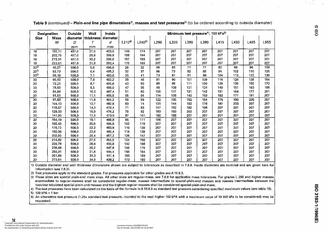
Table 9 (continued) - Plain-end line pipe dimensions’), masses and test pressures2) (to be ordered according to outside diameter)
Designation Outside Wall Inside Minimum test pressure4), 100 kPa5) Size Mass diameter thickness diameter
M D T d L2106) L2456) L290 L320 L360 L390 L415 L450 L485 L555 mm mm mm
18 192,ll 457,0 27.0 403,o 149 174 207 207 207 207 207 207 207 207 18 202,75 457,0 28,6 399,6 158 184 207 207 207 207 207 207 207 207 18 213,31 457,0 30,2 396,6 167 193 207 207 207 207 207 207 207 207
223,61 457,0 31,8 393,4 175 193 207 207 207 207 207 207 207 207 ;;31 46,27 508,O W 496,8 28 32 58 63 71 77 82 89 96 109 203’ 52.73 508,O 64 495,2 32 37 66 73 82 88 94 102 110 125 203’ 59,18 508,O 7,l 493,8 35 41 73 81 91 98 104 113 122 138 20 65,60 508,O 73 492.2 39 46 81 90 101 109 116 126 136 154 20 72,21 508,O 8,7 490,6 43 50 89 99 111 120 128 139 150 170 20 78,60 508,O 93 489,0 47 55 98 108 121 131 140 151 163 185 20 84,96 508,O IO,3 487,4 51 60 106 117 131 142 151 164 177 201 20 91,51 508,O II,1 485,8 55 64 114 126 142 153 163 177 191 207 20 97,83 508,O II,9 484,2 59 69 122 135 152 164 175 190 205 207 20 104,13 508,O 12,7 482,6 63 74 131 144 162 176 187 203 207 207 20 116,67 508,O 14,3 479,4 71 83 147 162 182 198 207 207 207 207 20 129,33 508.0 15.9 476,2 79 92 163 180 203 207 207 207 207 207 20 141,90 508,O 17,5 473,0 87 101 180 198 207 207 207 207 207 207 20 154,19 508,O 19,l 469,8 95 111 196 207 207 207 207 207 207 207 20 166.40 508,O 20,6 466,8 102 119 207 207 207 207 207 207 207 207 20 178,72 508.0 22.2 463,6 110 128 207 207 207 207 207 207 207 207 20 190,96 508,O 23,8 460,4 118 138 207 207 207 207 207 207 207 207 20 202.92 508,O 25,4 457.2 126 147 207 207 207 207 207 207 207 207 20 214,80 508,O 27,0 454.0 134 156 207 207 207 207 207 207 207 207 20 226,78 508,O 28,6 450,8 142 166 207 207 207 207 207 207 207 207 20 238,68 508,O 30,2 447,6 150 175 207 207 207 207 207 207 207 207 20 250,31 508,O 31,8 444,4 158 184 207 207 207 207 207 207 207 207 20 261,86 508,O 33,3 441,4 165 193 207 207 207 207 207 207 207 207 20 273,51 508,O 34.9 438,2 173 193 207 207 207 207 207 207 207 207
I) Outside diameter and wall thickness dimensions shown are subject to tolerances as described in 7.6.8. Inside diameters are nominal and are given here for information (see 7.6.2).
2) Test pressures apply to the standard grades. For pressures applicable for other grades see 8.10.9.3. 3) These sizes are special plain-end mass sizes. All other sizes are regular-mass, see 7.6.8 for applicable mass tolerances. For grades L 290 and higher masses
intermediate to regular-masses shall be considered regular-mass; masses intermediate to special-plain-end masses and masses intermediate between the heaviest tabulated special-plain-end masses and the highest regular-masses shall be considered special-plain-end mass.
1) The test pressures have been calculated on the basis of the formula in 8.10.9.3 as standard test pressure considering specified maximum values (see table 15). 5) lOOkPA=lbar 5) An alternative test pressure (1,25x standard test pressure, rounded to the next higher 100 kPA with a maximum value of 19 300 kPa to be considered) may be
requested.
Copyright International Organization for Standardization Provided by IHS under license with ISO Licensee=Aramco HQ/9980755100
Not for Resale, 04/12/2006 02:18:28 MDTNo reproduction or networking permitted without license from IHS
--``,,`,```````,`````,,,,,,`,`,-`-`,,`,,`,`,,`---

Table 9 (continued) - Plain-end line pipe dimensions’), masses and test pressures2) (to be ordered according to outside diameter)
Designation Outside Wall Inside Minimum test pressure4), 100 kPa5) Size Mass diameter thickness diameter
M D T d L210”’ L2456’ L290 L320 L360 L390 L415 L450 L485 L555 mm mm mm
223’ 50,94 559,0 5.6 547.8 25 29 52 58 65 70 75 81 87 99 223’ 58,07 559,0 6th 546.2 29 34 60 66 74 80 86 93 100 113 223’ 65,18 559,0 7,l 544,8 32 37 66 73 82 89 95 103 111 126 22 72,27 559,0 73 543,2 36 42 74 81 92 99 106 114 123 140 22 79,56 559,0 67 541,6 39 46 81 90 101 109 116 126 136 154 22 86,61 559,0 95 540,o 43 50 89 98 110 119 127 138 148 168 22 93,63 559,0 IO,3 538,4 46 54 96 106 119 129 138 149 161 182 22 100,86 559,0 II,1 536,8 50 58 104 114 129 139 148 161 173 197 22 107,85 559,0 II,9 535,2 54 63 111 123 138 149 159 172 186 207 22 114,81 559,0 12,7 533,6 57 67 119 131 147 159 170 184 198 207 22 126,67 559,0 14‘3 530,4 64 75 134 147 166 180 191 207 207 207 22 142,68 559.0 15.9 527,2 72 84 148 164 184 200 207 207 207 207 22 156.60 559.0 17.5 524,0 79 92 163 180 203 207 207 207 207 207 22 170,21 559,0 19,l 520,8 86 100 178 197 207 207 207 207 207 207 22 183,75 559,0 20,6 517,8 93 108 192 207 207 207 207 207 207 207 22 197.41 559,0 22.2 514,6 100 117 207 207 207 207 207 207 207 207 22 211,00 559,0 23,8 511,4 107 125 207 207 207 207 207 207 207 207 22 224,28 559,0 25,4 508,2 115 134 207 207 207 207 207 207 207 207 22 237,48 559,0 27,0 505,o 122 142 207 207 207 207 207 207 207 207 22 250,81 559,0 28.6 501.8 129 150 207 207 207 207 207 207 207 207 22 264,06 559,0 30,2 498.6 136 159 207 207 207 207 207 207 207 207 22 277,Ol 559,0 31,8 495,4 143 167 207 207 207 207 207 207 207 207 22 289,88 559,0 33,3 492,4 150 175 207 207 207 207 207 207 207 207 22 302,88 559,0 34,9 489,2 157 184 207 207 207 207 207 207 207 207 22 315,79 559.0 36,5 486.0 165 192 207 207 207 207 207 207 207 207 22 328.41 559,0 38,l 482,8 172 193 207 207 207 207 207 207 207 207 243’ 63,41 610.0 64 597,2 26 31 55 60 68 74 78 85 92 104 243’ 71.18 610.0 7,l 595,8 29 34 61 67 75 82 87 94 102 115 24 78,93 610,O 73 594,2 33 38 68 75 84 91 97 105 113 128 24 86,91 610,O 8,7 592,6 36 42 74 82 92 100 107 116 125 141 24 94,62 610,O 9.5 591,0 39 46 81 90 101 109 116 126 136 154
I) Outside diameter and wall thickness dimensions shown are subject to tolerances as described in 7.6.8. Inside diameters are nominal and are given here fol information (see 7.6.2).
!) Test pressures apply to the standard grades. For pressures applicable for other grades see 8.10.9.3. I) These sizes are special plain-end mass sizes. All other sizes are regular-mass, see 7.6.8 for applicable mass tolerances. For grades L 290 and higher masse!
intermediate to regular-masses shall be considered regular-mass; masses intermediate to special-plain-end masses and masses intermediate between tht heaviest tabulated special-plain-end masses and the highest regular-masses shall be considered special-plain-end mass.
1) The test pressures have been calculated on the basis of the formula in 8.10.9.3 as standard test pressure considering specified maximum values (see table 15). i) 100 kPA = 1 bar i) An alternative test pressure (1,25x standard test pressure, rounded to the next higher 100 kPA with a maximum value of 19 300 kPa to be considered) may bc
requested. Copyright International Organization for Standardization Provided by IHS under license with ISO Licensee=Aramco HQ/9980755100
Not for Resale, 04/12/2006 02:18:28 MDTNo reproduction or networking permitted without license from IHS
--``,,`,```````,`````,,,,,,`,`,-`-`,,`,,`,`,,`---
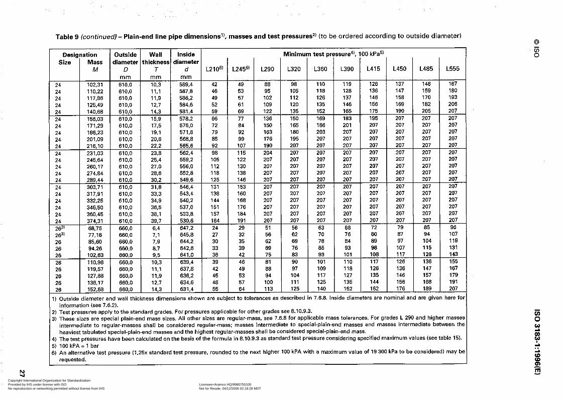
Y
Table 9 (continued) - Plain-end line pipe dimensions’), masses and test pressuresz) (to be ordered according to outside diameter)
Designation Outside Wall Inside Minimum test pressure4), 100 kPa5) Size Mass diameter thickness diameter
M D T d L21 06) L2456) L290 L320 L360 L390 L415 L450 L485 L555 m m m m m m
24 102,31 610,O IO,3 589,4 42 49 88 98 110 119 126 137 148 167 24 110,22 610,O 11,l 587,8 46 53 95 105 118 128 136 147 159 180 24 117.86 610,O 11.9 586,2 49 57 102 112 126 137 146 158 170 193 24 125,49 610,O 12,7 584,6 52 61 109 120 135 146 156 169 182 206 24 140.68 610,O 14,3 581,4 59 69 122 135 152 165 175 190 205 207 24 156.03 610,O 15,9 578.2 66 77 136 150 169 183 195 207 207 207 24 171.29 610,O 17,5 575,0 72 84 150 165 186 201 207 207 207 207 24 186,23 610,O 19,l 571,8 79 92 163 180 203 207 207 207 207 207 24 201,09 610.0 20,6 568,8 85 99 176 195 207 207 207 207 207 207 24 216,lO 610,O 22,2 565,6 92 107 190 207 207 207 207 207 207 207 24 231,03 610,O 23,8 562.4 98 115 204 207 207 207 207 207 207 207 24 245,64 610,O 25,4 559.2 105 122 207 207 207 207 207 207 207 207 24 260,17 610,O 27,0 556.0 112 130 207 207 207 207 207 207 207 207 24 274,84 610,O 28.6 552.8 118 138 207 207 207 207 207 207 207 207 24 289,44 610,O 30.2 549,6 125 146 207 207 207 207 207 207 207 207 24 303.71 610,O 31,8 546,4 131 153 207 207 207 207 207 207 207 207 24 317,91 610,O 33,3 543.4 138 160 207 207 207 207 207 207 207 207 24 332,25 610,O 34,9 540,2 144 168 207 207 207 207 207 207 207 207 24 346,50 610,O 36,5 537,0 151 176 207 207 207 207 207 207 207 207 24 360,45 610.0 38,l 533.8 157 184 207 207 207 207 207 207 207 207 24 374,31 610.0 39,7 530.6 164 191 207 207 207 207 207 207 207 207 263' 68,75 660,O 64 647.2 24 29 51 56 63 68 72 79 85 96 263' 77,18 660,O 7,1 645,8 27 32 56 62 70 76 80 87 94 107 26 85,60 660,O 789 644,2 30 35 62 69 78 84 89 97 104 119 26 94,26 660.0 67 642,6 33 39 69 76 85 93 98 107 115 131 26 102,63 660,O 93 641,0 36 42 75 83 93 101 108 117 126 143 26 1 IO,98 660,O IO,3 639,4 39 46 81 90 101 110 117 126 136 155 26 119,57 660,O 11,l 637,8 42 49 88 97 109 118 126 136 147 167 26 127,88 660,O II,9 636,2 45 53 94 104 117 127 135 146 157 179 26 136,17 660,O 12,7 634,6 48 57 100 111 125 135 144 156 168 191 26 152,68 660,O 14,3 631,4 55 64 113 125 140 152 162 176 189 207
1) Outside diameter and wall thickness dimensions shown are subject to tolerances as described in 7.6.8. Inside diameters are nominal and are given here for information (see 7.6.2).
2) Test pressures apply to the standard grades. For pressures applicable for other grades see 8.10.9.3. 3) These sizes are special plain-end mass sizes. All other sizes are regular-mass, see 7.6.8 for applicable mass tolerances. For grades L 290 and higher masses
intermediate to regular-masses shall be considered regular-mass; masses intermediate to special-plain-end masses and masses intermediate between the heaviest tabulated special-plain-end masses and the highest regular-masses shall be considered special-plain-end mass.
4) The test pressures have been calculated on the basis of the formula in 8.10.9.3 as standard test pressure considering specified maximum values (see table 15). 5) lOOkPA=l bar 3) An alternative test pressure (1,25x standard test pressure, rounded to the next higher 100 kPA with a maximum value of 19 300 kPa to be considered) may be
requested.
Copyright International Organization for Standardization Provided by IHS under license with ISO Licensee=Aramco HQ/9980755100
Not for Resale, 04/12/2006 02:18:28 MDTNo reproduction or networking permitted without license from IHS
--``,,`,```````,`````,,,,,,`,`,-`-`,,`,,`,`,,`---

Table 9 (continued) - Plain-end line pipe dimensions’), masses and test pressures2) (to be ordered according
Designation Outside Wall Inside Minimum test pressure4), 100 kPa5) Size Mass diameter thickness diameter
M D T d L2106’ L2456’ L290 L320 L360 L390 L415 m m m m m m
26 169,38 660,O 15.9 628,2 61 71 126 139 156 169 180 26 185,99 660,O 17,5 625,0 67 78 138 153 172 186 198 26 202,25 660,O 19,l 621,8 73 85 151 167 188 203 207 26 218,43 660,O 20,6 618,8 79 92 163 180 202 207 207 26 234,79 660,O 22,2 615,6 85 99 176 194 207 207 207 26 251,07 660,O 23,8 612,4 91 106 188 207 207 207 207 26 267,OO 660,O 25,4 609,2 97 113 201 207 207 207 207 283’ 74,09 711,o ‘54 698,2 23 26 47 52 58 63 67 283’ 83,19 711,o 7,l 696,8 25 29 52 58 65 70 75 28 92,26 711,o 73 695,2 28 33 58 64 72 78 83 28 101,61 711,o 8,7 693.6 31 36 64 70 79 86 91 28 1 lo,64 711,o 93 692,0 34 39 70 77 87 94 100 28 119,65 711,o IO,3 690,4 37 43 76 83 94 102 108 28 128,93 711.0 11.1 688.8 39 46 81 90 101 110 117 28 137,90 711,o II,9 687,2 42 49 87 96 108 117 125 28 146.85 711,o 12,7 685,6 45 53 93 103 116 125 133 28 164,69 711,o 14.3 682.4 51 59 105 116 130 141 150 28 182,73 711,o 15,9 679.2 56 66 117 129 145 157 167 28 200,68 711,o 17.5 676,O 62 72 128 142 159 173 184 28 218,27 711,o 19,l 672.8 68 79 140 155 174 189 201 28 235,78 711,o 20,6 669,8 73 85 151 167 188 203 207 28 253,48 711,o 22,2 666,6 79 92 163 180 202 207 207 28 271.10 711,o 23,8 663,4 84 98 175 193 207 207 207 28 288,36 711,o 25,4 660,2 90 105 186 206 207 207 207 303’ 79,43 762.0 64 749,2 21 25 44 48 54 59 63 303’ 89.19 762,O 7,1 747.8 23 27 49 54 60 65 70 30 98,93 762,O 73 746,2 26 30 54 60 67 73 77 30 108,95 762,O 887 744,6 29 34 60 66 74 80 85 30 118.65 762,O 93 743,o 31 37 65 72 81 88 93
I) Outside diameter and wall thickness dimensions shown are subject to tolerances as described in 7.6.8. Inside diameters are information (see 7.6.2).
!) Test pressures apply to the standard grades. For pressures applicable for other grades see 8.10.9.3. i) These sizes are special plain-end mass sizes. All other sizes are regular-mass, see 7.6.8 for applicable mass tolerances. For grades
intermediate to regular-masses shall be considered regular-mass; masses intermediate to special-plain-end masses and masses heaviest tabulated special-plain-end masses and the highest regular-masses shall be considered special-plain-end mass.
I) The test pressures have been calculated on the basis of the formula in 8.10.9.3 as standard test pressure considering specified maximum i) 100 kPA = 1 bar i) An alternative test pressure (1,25x standard test pressure, rounded to the next higher 100 kPA with a maximum value of 19 300
requested.
Copyright International Organization for Standardization Provided by IHS under license with ISO Licensee=Aramco HQ/9980755100
Not for Resale, 04/12/2006 02:18:28 MDTNo reproduction or networking permitted without license from IHS
--``,,`,```````,`````,,,,,,`,`,-`-`,,`,,`,`,,`---

Table 9 (continued) - Plain-end line pipe dimensionsl), masses and test pressures*) (to be ordered according
Designation Outside Wall Inside Minimum test pressure4), 100 kPa5) Size Mass diameter thickness diameter
M D T d L2106’ L2456’ L290 L320 L360 L390 L415 mm mm mm
30 128,32 762,0 IO,3 741,4 34 40 71 78 88 95 101 30 138,29 762,0 II,1 739,8 37 43 76 84 94 102 109 30 147,92 762,0 II,9 738,2 39 46 82 90 101 110 117 30 157,53 762,0 12,7 736,6 42 49 87 96 108 117 125 30 176,69 762,0 14,3 733,4 47 55 98 108 122 132 140 30 196,08 762,0 15,9 730,2 53 61 109 120 135 146 156 30 215,38 762,0 17,5 727,0 58 68 120 132 149 161 172 30 234,29 762,0 19,l 723,8 63 74 131 144 162 176 187 30 253.12 762,0 20‘6 720,8 68 79 141 156 175 190 202 30 272,17 762,0 22,2 717,6 73 86 152 168 189 205 207 30 291,14 762,0 23,8 714,4 79 92 163 180 202 207 207 30 309,72 762,0 25,4 711,2 84 98 174 192 207 207 207 30 328,22 762,0 27,0 708,O 89 104 185 204 207 207 207 30 346,93 762.0 28,6 704,8 95 110 196 207 207 207 207 30 365,56 762.0 30,2 701,6 100 117 207 207 207 207 207 30 383,81 762,0 31,8 698,4 105 123 207 207 207 207 207 323' 84,77 813,0 ‘54 800,2 20 23 41 45 51 55 59 323' 95,19 813,0 7.1 798,8 22 26 46 50 57 61 65 32 105,59 813,0 7,s 797,2 24 29 51 56 63 68 73 32 116,30 813,0 8,7 795,6 27 31 56 62 69 75 80 32 126,66 813,0 9,5 794,0 29 34 61 67 76 82 87 32 136,99 813,0 IO,3 792,4 32 37 66 73 82 89 95 32 147,64 813,0 II,1 790,8 34 40 71 79 88 96 102 32 147,94 813.0 II,9 789,2 37 43 76 84 95 103 109 32 168.21 813,0 12,7 787.6 39 46 82 90 101 110 117 32 188,70 813,0 14.3 784,4 44 52 92 101 114 123 131 32 209,43 813,0 15,9 781,2 49 57 102 113 127 137 146 32 230,08 813,0 17,5 787,0 54 63 112 124 139 151 161 32 250,31 813,0 IS,1 774.8 59 69 123 135 152 165 175 32 270,47 813,0 20,6 771,8 64 74 132 146 164 178 189 32 290,86 813,0 22.2 768,6 69 80 143 157 177 192 204
) Outside diameter and wall thickness dimensions shown are subject to tolerances as described in 7.6.8. Inside diameters are nominal information (see 7.6.2).
) Test pressures apply to the standard grades. For pressures applicable for other grades see 8.10.9.3. ) These sizes are special plain-end mass sizes. All other sizes are regular-mass, see 7.6.8 for applicable mass tolerances. For grades
intermediate to regular-masses shall be considered regular-mass; masses intermediate to special-plain-end masses and masses heaviest tabulated special-plain-end masses and the highest regular-masses shall be considered special-plain-end mass.
) The test pressures have been calculated on the basis of the formula in 8.10.9.3 as standard test pressure considering specified maximum ) 100 kPA = 1 bar ) An alternative test pressure (1,25x standard test pressure, rounded to the next higher 100 kPA with a maximum value of 19 300
requested.
Copyright International Organization for Standardization Provided by IHS under license with ISO Licensee=Aramco HQ/9980755100
Not for Resale, 04/12/2006 02:18:28 MDTNo reproduction or networking permitted without license from IHS
--``,,`,```````,`````,,,,,,`,`,-`-`,,`,,`,`,,`---

Table 9 (continued) - Plain-end line pipe dimensions’), masses and test pressures*) (to be ordered according to outside diameter)
Designation Outside Wall Inside Minimum test pressure4), 100 kPa5) Size Mass diameter thickness diameter
M D T d L210”) L245’j’ L290 L320 L360 L390 L415 L450 L485 L555 mm mm mm
32 311,17 813,0 23,8 765,4 74 86 153 169 190 206 207 207 207 207 32 331,08 813,0 25,4 762.2 79 92 163 180 202 207 207 207 207 207 32 350,90 813.0 27,0 759,0 84 98 173 191 207 207 207 207 207 207 32 370,96 813,0 28,6 755.8 89 103 184 203 207 207 207 207 207 207 32 390,94 813,0 30,2 752.6 94 109 194 207 207 207 207 207 207 207 32 410.51 813,0 31.8 749.4 99 115 204 207 207 207 207 207 207 207 343’ 90,ll 864,0 64 851,2 19 22 39 43 48 52 55 60 65 73 343’ 101,19 864,0 7,l 849.8 21 24 43 47 53 58 61 67 72 81 34 112,25 864,0 73 848,2 23 27 48 53 59 64 68 74 80 91 34 123,65 864,0 8,7 846,6 25 30 53 58 65 71 75 82 88 100 34 134,67 864,0 c-5 845,0 28 32 57 63 71 77 82 89 96 109 34 145,67 864,0 IO,3 843,4 30 35 62 69 77 84 89 97 104 118 34 157,00 864,0 11.1 841,8 32 38 67 74 83 90 96 104 112 127 34 167,95 864,0 II,9 840,2 35 40 72 79 89 97 103 112 120 136 34 178,89 864,0 12.7 838,6 37 43 77 85 95 103 110 119 128 146 34 200,70 864,0 14,3 835,4 42 49 86 95 107 116 124 134 144 164 34 222,78 864,0 15,9 832,2 46 54 96 106 119 129 137 149 161 182 34 244,77 864,0 17,5 829,0 51 60 106 117 131 142 151 164 177 201 34 266.33 864,0 19,l 825,8 56 65 115 127 143 155 165 179 193 207 34 287.81 864,0 20,6 822.8 60 70 124 137 155 167 178 193 207 207 34 309,55 864,0 22,2 819,6 65 76 134 148 167 180 192 207 207 207 34 331,21 864,0 23,8 816,4 69 81 144 159 179 193 206 207 207 207 34 352,44 864,0 25,4 813,2 74 86 153 169 191 206 207 207 207 207 34 373,59 864,0 27,0 810,O 79 92 163 180 203 207 207 207 207 207 34 394,99 864.0 28,6 806,8 83 97 173 191 207 207 207 207 207 207 34 416,31 864,0 30,2 803,6 88 103 182 201 207 207 207 207 207 207 34 437,21 864,0 31,8 800,4 93 108 192 207 207 207 207 207 207 207 363’ 95,45 914,0 64 901,2 18 21 37 40 45 49 52 57 61 69 363’ 107,20 914,0 7,l 899,8 20 23 41 45 50 55 58 63 68 77 36 118,92 914,0 73 898,2 22 25 45 50 56 61 65 70 75 86 36 131,00 914,0 8,7 896,6 24 28 50 55 62 67 71 77 83 94
I) Outside diameter and wall thickness dimensions shown are subject to tolerances as described in 7.6.8. Inside diameters are nominal and are given here for information (see 7.6.2).
2) Test pressures apply to the standard grades. For pressures applicable for other grades see 8.10.9.3. 3) These sizes are special plain-end mass sizes. All other sizes are regular-mass, see 7.6.8 for applicable mass tolerances. For grades L 290 and higher masse:
intermediate to regular-masses shall be considered regular-mass; masses intermediate to special-plain-end masses and masses intermediate between the heaviest tabulated special-plain-end masses and the highest regular-masses shall be considered special-plain-end mass.
4) The test pressures have been calculated on the basis of the formula in 8.10.9.3 as standard test pressure considering specified maximum values (see table 15). 5) 100 kPA = 1 bar 5) An alternative test pressure (1,25x standard test pressure, rounded to the next higher 100 kPA with a maximum value of 19 300 kPa to be considered) may br
requested. Copyright International Organization for Standardization Provided by IHS under license with ISO Licensee=Aramco HQ/9980755100
Not for Resale, 04/12/2006 02:18:28 MDTNo reproduction or networking permitted without license from IHS
--``,,`,```````,`````,,,,,,`,`,-`-`,,`,,`,`,,`---
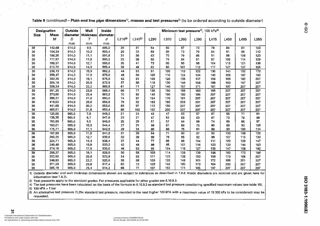
1
Table 9 (continued) - Plain-end line pipe dimensionsl), masses and test pressures2) (to be ordered according to outside diameter)
Designation Outs ide W all Inside Minimum test pressure4), 100 kPa5) Size Mass diameter thickness diameter
M D T d L21 06) L2456’ L290 L320 L360 L390 L415 L450 L485 L555 mm mm mm
36 142,68 914,0 93 895,0 26 31 54 60 67 73 78 84 91 103 36 154,34 914,0 IO,3 893,4 28 33 59 65 73 79 84 91 98 112 36 166,35 914,0 II,1 891,8 31 36 63 70 79 85 91 98 106 120 36 177.97 914,0 II,9 890,2 33 38 68 75 84 91 97 105 114 129 36 189,57 914,0 12,7 888,6 35 41 73 80 90 98 104 113 121 138 36 212,70 914,0 14,3 885,4 39 46 82 90 101 110 117 127 137 155 36 236.13 914,0 15,9 882,2 44 51 91 100 113 122 130 141 152 172 36 259.47 914,0 17,5 879,0 48 56 100 110 124 134 143 155 167 190 36 282.35 914,0 19,l 875,8 53 61 109 120 135 147 156 169 182 207 36 305,16 914,0 20,6 872,8 57 66 118 130 146 158 168 183 197 207 36 328.24 914,0 22,2 869,6 61 71 127 140 157 171 181 197 207 207 36 351,25 914,0 23,8 866,4 66 77 136 150 169 183 195 207 207 207 36 373,80 914,0 25,4 863,2 70 82 145 160 180 195 207 207 207 207 36 396,27 914,0 27.0 860.0 74 87 154 170 191 207 207 207 207 207 36 419,02 914,0 28,6 856,8 79 92 163 180 203 207 207 207 207 207 36 441.69 914.0 30,2 853.6 83 97 172 190 207 207 207 207 207 207 36 463,91 914,0 31,8 850.4 88 102 182 200 207 207 207 207 207 207 38 125,58 965,0 789 949,2 21 24 43 47 53 57 61 66 71 81 38 138,35 965,0 8.7 947,6 23 27 47 52 58 63 67 73 79 89 38 150.69 965,0 985 946,0 25 29 51 57 64 69 74 80 86 97 38 163,Ol 965,0 IO,3 944,4 27 31 56 61 69 75 80 86 93 106 38 175,71 965,0 II,1 942,8 29 34 60 66 75 81 86 93 100 114 38 187,99 965,0 II,9 941,2 31 36 64 71 80 87 92 100 108 122 38 200,25 965,0 12.7 939,6 33 39 69 76 85 92 98 107 115 130 38 224.71 965,0 14,3 936,4 37 44 77 85 96 104 111 120 129 147 38 249,48 965,0 15,9 933,2 42 48 86 95 107 116 123 133 144 163 38 274,16 965,0 17,5 930,o 46 53 95 104 118 127 135 147 158 180 38 298,37 965,0 19,l 926,8 50 58 103 114 128 139 148 160 173 196 38 322,50 965,0 20,6 923,8 54 63 111 123 138 150 159 173 186 207 38 346,93 965,0 22.2 920,6 58 68 120 133 149 161 172 186 201 207 38 371,28 965,0 23.8 917,4 62 73 129 142 160 173 184 200 207 207 38 395,16 965,0 25.4 914.2 66 77 137 152 171 185 197 207 207 207
) Outside diameter and wall thickness dimensions shown are subject to tolerances as described in 7.6.8. Inside diameters are nominal and are given here for information (see 7.6.2).
!) Test pressures apply to the standard grades. For pressures applicable for other grades see 8.10.9.3. .) The test pressures have been calculated on the basis of the formula in 8.10.9.3 as standard test pressure considering specified maximum values (see table 15). ;) 100 kPA = 1 bar i) An alternative test pressure (1,25x standard test pressure, rounded to the next higher 100 kPA with a maximum value of 19 300 kPa to be considered) may be
requested.
Copyright International Organization for Standardization Provided by IHS under license with ISO Licensee=Aramco HQ/9980755100
Not for Resale, 04/12/2006 02:18:28 MDTNo reproduction or networking permitted without license from IHS
--``,,`,```````,`````,,,,,,`,`,-`-`,,`,,`,`,,`---
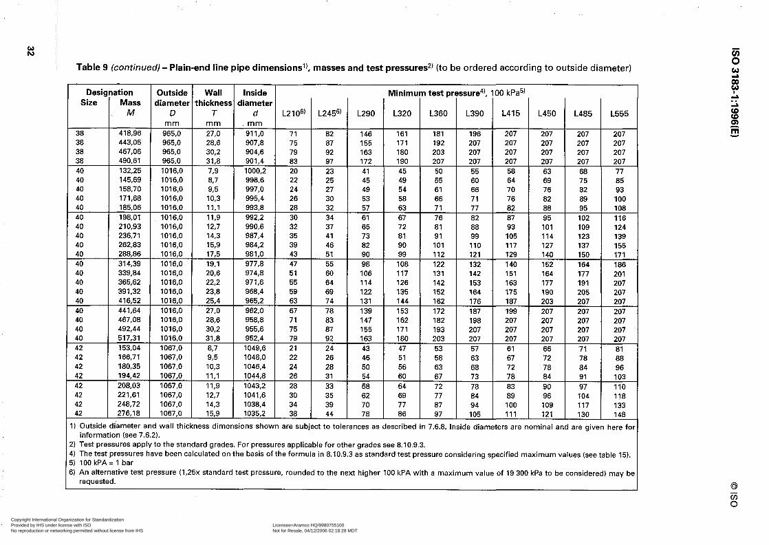
Table 9 (continuedl - Plain-end line pipe dimensions’), masses and test pressures*) (to be ordered according to outside diameter)
Designation Outside Wall Inside Minimum test pressure4), 100 kPa5) Size Mass diameter thickness diameter
M D T d L2106’ L2456’ L290 L320 L360 L390 L415 L450 L485 L555 mm mm mm
38 418,96 965,0 27,0 911,o 71 82 146 161 181 196 207 207 207 207 38 443,05 965,0 28,6 907,8 75 87 155 171 192 207 207 207 207 207 38 467,06 965,0 30,2 904,6 79 92 163 180 203 207 207 207 207 207 38 490,61 965,0 31,8 901,4 83 97 172 190 207 207 207 207 207 207 40 132.25 1016,O 73 1000,2 20 23 41 45 50 55 58 63 68 77 40 145,69 1016,O 67 998,6 22 25 45 49 55 60 64 69 75 85 40 158,70 1016,O 93 997,0 24 27 49 54 61 66 70 76 82 93 40 171,68 1016.0 IO,3 995,4 26 30 53 58 66 71 76 82 89 100 40 185,06 1016,O II,1 993,8 28 32 57 63 71 77 82 88 95 108 40 198,Ol 1016,O II,9 992,2 30 34 61 67 76 82 87 95 102 116 40 210,93 1016,O 12,7 990.6 32 37 65 72 81 88 93 101 109 124 40 236,71 1016,O 14,3 987,4 35 41 73 81 91 99 105 114 123 139 40 262,83 1016,O 15,9 984,2 39 46 82 90 101 110 117 127 137 155 40 288,86 1016,O 17,5 981,0 43 51 90 99 112 121 129 140 150 171 40 314.39 1016,O 19,l 977,8 47 55 98 108 122 132 140 152 164 186 40 339,84 1016,O 20,6 974,8 51 60 106 117 131 142 151 164 177 201 40 365,62 1016,O 22,2 971,6 55 64 114 126 142 153 163 177 191 207 40 391,32 1016.0 23‘8 968,4 59 69 122 135 152 164 175 190 205 207 40 416,52 1016,O 25,4 965,2 63 74 131 144 162 176 187 203 207 207 40 441,64 1016,O 27,0 962,0 67 78 139 153 172 187 199 207 207 207 40 467,08 1016,O 28,6 958,8 71 83 147 162 182 198 207 207 207 207 40 492,44 1016,O 30.2 955,6 75 87 155 171 193 207 207 207 207 207 40 517,31 1016,O 31,8 952,4 79 92 163 180 203 207 207 207 207 207 42 153.04 1067,O 887 1049,6 21 24 43 47 53 57 61 66 71 81 42 166.71 1067,O 93 1048,O 22 26 46 51 58 63 67 72 78 88 42 180,35 1067,O IO,3 1046,4 24 28 50 56 63 68 72 78 84 96 42 194,42 1067,O II,1 1044,8 26 31 54 60 67 73 78 84 91 103 42 208,03 1067,O II,9 1043,2 28 33 58 64 72 78 83 90 97 110 42 221,61 1067,O 12,7 1041,6 30 35 62 69 77 84 89 96 104 118 42 248,72 1067,O 14,3 1038,4 34 39 70 77 87 94 100 109 117 133 42 276,18 1067,O 15,9 1035.2 38 44 78 86 97 105 111 121 130 148
I) Outside diameter and wall thickness dimensions shown are subject to tolerances as described in 7.6.8. Inside diameters are nominal and are given here for information (see 7.6.2).
!) Test pressures applytothe standard grades. For pressures applicable for other grades see 8.10.9.3. I) Thetestpressures have been calculated on the basis oftheformula in 8.10.9.3 as standardtestpressureconsidering specified maximumvalues(seetable 15). i) lOOkPA=l bar i) An alternative test pressure (1,25x standard test pressure, rounded to the next higher 100 kPA with a maximum value of 19 300 kPa to be considered) may be
requested.
~~-,-=- ._-. _ __., r -- .I ----. , - ,.---? .-.. ~--~.-. --.- ~. .-___..._ c ._../--- ..-_-_. ~._,- .__ _j_l
Copyright International Organization for Standardization Provided by IHS under license with ISO Licensee=Aramco HQ/9980755100
Not for Resale, 04/12/2006 02:18:28 MDTNo reproduction or networking permitted without license from IHS
--``,,`,```````,`````,,,,,,`,`,-`-`,,`,,`,`,,`---

Table 9 (continued) - Plain-end line pipe dimensionsl), masses and test pressures*) (to be ordered according to outside diameter)
Desi! Size
gni ation Mass
M ’ 1
Outside diameter
D mm
1067,O 1067,O 1067,O 1067,O 1067,O 1067,O 1067,O 1067,O 1067,O 1067.0 1118,0 1118,0 1118,0 1118,0 1118,0 1118,0 1118,O 1118,O 1118.0 1118,O 1118,0 1118.0 1118,0 1118.0 1118,0 1118,0 1118,0 1118.0 1168,0 1168.0 1168,O 11660 11660
i (
Minimb test PI
L210”’ I I
L2456’ L290 L320 L360 L390 L415 L450 L485 L555
42 42 42 42 42 42 42 42 42 42 44 44 44 44 44 44 44 44 44 44
- - 94 106 115 123 133 143 162 103 116 126 134 145 156 177 111 125 136 144 156 169 191 120 135 -T- 146 155 169 182 206
56 1 66 1 116 128 145 60 1 70 1 124
- - 137 154 -%--l-e -zi--E- 207
207 64 74 132 146 164 205 207 207 68
I 79
I 140 154 174 207 207 207
71 83 148 163 183 207 207 207 75 1 88 1 156 172 193 207 207 207 - - 20 1 23 ) 41 45 50 63 68 77 21 I 25 I 44 49 55 69 74 84 23 27 48 53 60 75 80 91 25 29 52 57 64 80 87 98 27 1 31 ) 56 61 69 105
1 - -
29 33 59 65 74 112 32
I
1
I
-4-t-+- -+I+ 38 67 74 83 90 96 104 112 127
36 42 74 82 92 100 106 115 124 141 39 46 82 90 101 110 117 127 137 155 43 50 89 98 111 169 - -
44 46 54 96 106 119 182 44 50 58 104 114 129 139 148 161 173 197 44 54 63 111 123 138 149 159 172 186 207 44 57 1 67 1 119 131 147 207
61 1 71 1 126 - -
44 139 156 207 44 64 I 75 134 147 166 207 207 207 44 68 79
I 141 156 175 207 207 207
44 72 1 84 1 148 164 184 207 207 207 - - 46 20 1 23 1 41 45
I I 50 63 68 77
46 21 25 44 49 55 69 74 84 46 23 27 48 53 60 75 80 91 46 25 29 52 57 64 80 87 98 46 27 1 31 [ 56 61 69 86 93 105 - -
I) Outside diameter and wall thickness dimensions shown are subject to tolerances as described in 7.6.8. Inside diameters are nominal and are given here fo information (see7.6.2).
!) Test pressures applytothe standard grades. For pressures applicable for other grades see 8.10.9.3. I) Thetest pressures have been calculated on the basis ofthe formula in 8.10.9.3 as standard test pressure considering specified maximum values (seetable 15). i) 100 kPA=l bar i) An alternative test pressure (1,25x standard test pressure, roundedtothe next higher 100 kPA with a maximum value of 19 300 kPa to be considered) may bc
requested.
303,55 330,41 357,19 384,31 411,35 437,88 464,33 491,ll 517,82 544,Ol 160,39 174.72 189,03 203,78 218,04 232,29 260,72 289,53 318,25 346,43 374,53 403,oo 431.39 459.24 487,Ol 515,14 543,19 570,71 167,74 182,73 197,70 213,13 228,06
Wall :hicknesz
T mm 17,5 19,l 20,6 22,2 23,8 25,4 27,0 28,6 30,2 31.8 8,7 9‘5 IO,3 II,1 II,9 12,7 14.3 15,9 17,5 19,l 20,6 22,2 23,8 25,4 27,0 28,6 30,2 31,8 8,7 93 IO,3 II,1 II,9
Inside Gameter
d mm
1032,O 1028,8 1025,8 1022,6 1019,4 1016,2 1013,o 1009,8 1006,6 1003,4 1100,6 1099,o 1097,4 1095,8 1094,2 1092,6 1089,4 1086,2 1083,O 1079,8 1076,8 1073,6 1070.4 1067,2 1064,O 1060,8 1057,6 1054.4 1150,6 1149,0 1147,4 1145,8 1144,2
;sure4), 100 kPa5)
Copyright International Organization for Standardization Provided by IHS under license with ISO Licensee=Aramco HQ/9980755100
Not for Resale, 04/12/2006 02:18:28 MDTNo reproduction or networking permitted without license from IHS
--``,,`,```````,`````,,,,,,`,`,-`-`,,`,,`,`,,`---

Table 9 (continued) - Plain-end line pipe dimensions’), masses and test pressures*) (to be ordered according to outside diameter)
Designation Outside Wall Inside Minimum test pressure4), 100 kPa5) Size Mass diameter thickness diameter
M D T d L2106’ L2456’ L290 L320 L360 L390 L415 L450 L485 L555 m m m m m m
46 242.97 1168,O 12,7 1142.6 29 33 59 65 74 80 85 92 99 112 46 272,73 1168,O 14,3 1139,4 32 38 67 74 83 90 96 104 112 127 46 302,88 1168,O 15,9 1136,2 36 42 74 82 92 100 106 115 124 141 46 332,95 1168,O 17,5 1133,0 39 46 82 90 101 110 117 127 137 155 46 362,45 1168.0 19,l 1129,8 43 50 89 98 111 120 128 138 149 169 46 391,88 1168,O 20,6 1126,8 46 54 96 106 119 129 138 149 161 182 46 421,69 1168,O 22,2 1123.6 50 58 104 114 129 139 148 161 173 197 46 451,42 1168,O 23,8 1120.4 54 63 111 123 138 149 159 172 186 207 46 480,60 1168,O 25,4 1117,2 57 67 119 131 147 159 170 184 198 207 46 509,69 1168,O 27,0 1114,0 61 71 126 139 156 170 180 196 207 207 46 539,17 1168,O 28,6 1110,8 64 75 134 147 166 180 191 207 207 207 46 568,57 1168,O 30.2 1107,6 68 79 141 156 175 190 202 207 207 207 46 597.41 1168,O 31,8 1104,4 72 84 148 164 184 200 207 207 207 207 48 175,08 1219,0 87 1201.6 18 21 37 41 46 50 53 58 62 71 48 190,74 1219.0 9.5 1200.0 20 23 41 45 51 55 58 63 68 77 48 206,37 1219,0 IO,3 1198.4 21 25 44 49 55 59 63 68 74 84 48 222,49 1219,0 II,1 1196,8 23 27 48 52 59 64 68 74 79 90 46 238,08 1219.0 II,9 1195,2 25 29 51 56 63 69 73 79 85 97 48 253,65 1219,0 12,7 1193,6 26 31 54 60 68 73 78 84 91 103 48 284,73 1219.0 14,3 1190,4 30 34 61 68 76 82 88 95 102 116 48 316.23 1219.0 15,9 1187,2 33 38 68 75 85 92 97 106 114 129 48 347.64 1219,0 17.5 1184,0 36 42 75 83 93 101 107 116 125 142 48 378.47 1219,0 19,l 1180.8 39 46 82 90 102 110 117 127 137 155 48 409,22 1219,0 20,6 1177.8 43 50 88 97 110 119 126 137 148 167 48 440,38 1219,0 22,2 1174.6 46 54 95 105 118 128 136 148 159 180 48 471,46 1219,0 23,8 1171,4 49 57 102 112 127 137 146 158 170 193 48 501,96 1219.0 25.4 1168.2 53 61 109 120 135 146 156 169 182 206 48 532,38 1219,0 27,0 1165.0 56 65 116 128 144 155 165 179 193 207 48 563,20 1219,0 28,6 1161.8 59 69 122 135 152 165 175 190 205 207 48 593,94 1219,0 30.2 1158,6 62 73 129 143 161 174 185 201 207 207 48 624,ll 1219.0 31,8 1155,4 66 77 136 150 169 183 195 207 207 207
I) Outside diameter and wall thickness dimensions shown are subject to tolerances as described in 7.6.8. Inside diameters are nominal and are given here for information (see 7.6.2).
!) Test pressures apply to the standard grades. For pressures applicable for other grades see 8.10.9.3. 4) The test pressures have been calculated on the basis of the formula in 8.10.9.3 as standard test pressure considering specified maximum values (see table 15). 5) 100 kPA = 1 bar 5) An alternative test pressure (1,25x standard test pressure, rounded to the next higher 100 kPA with a maximum value of 19 300 kPa to be considered) may br
requested.
Copyright International Organization for Standardization Provided by IHS under license with ISO Licensee=Aramco HQ/9980755100
Not for Resale, 04/12/2006 02:18:28 MDTNo reproduction or networking permitted without license from IHS
--``,,`,```````,`````,,,,,,`,`,-`-`,,`,,`,`,,`---

Table 9 (continue4 - Plain-end line pipe dimensions’), masses and test pressures2) (to be ordered according to outside diameter)
Designation Outside Wall Inside Minimum test pressure4), 100 kPa5) Size Mass diameter thickness diameter
M D T d L2106’ L2456’ L290 L320 L360 L390 L415 L450 L485 L555 m m m m m m
52 206,76 1321,0 9.5 1302,O 16 21 38 41 47 50 54 58 63 71 52 223,72 1321,0 IO,3 1300,4 20 23 41 45 51 55 58 63 68 77 52 241,20 1321,0 II,1 1298,8 21 25 44 48 54 59 63 68 73 83 52 258,ll 1321,0 II,9 1297,2 23 26 47 52 58 63 67 73 79 89 52 275,Ol 1321,0 12,7 1295,6 24 28 50 55 62 67 72 78 84 95 52 308,74 1321,0 14,3 1292.4 27 32 57 62 70 76 81 88 95 107 52 342.93 1321,0 15,9 1289.2 30 35 63 69 78 84 90 97 105 119 52 377,03 1321,0 17,5 1286,0 33 39 69 76 86 93 99 107 116 131 52 410,51 1321,0 19,l 1282.8 36 43 75 83 94 102 108 117 126 143 52 443,91 1321,0 20,6 1279.8 39 46 81 90 101 109 116 126 136 154 52 477,76 1321,0 22,2 1276,6 42 49 88 97 109 118 126 136 147 166 52 51 I,53 1321,0 23,8 1273,4 45 53 94 104 117 126 135 146 157 178 52 544,68 1321,0 25,4 1270.2 48 57 100 111 125 135 144 156 168 190 52 577.75 1321,0 27,0 1267,0 52 60 107 118 132 143 153 166 178 202 52 611,26 1321,0 28,6 1263.8 55 64 113 125 140 152 162 175 189 207 52 644,69 1321,0 30,2 1260.6 58 67 119 132 148 160 171 185 200 207 52 677.51 1321,0 31,8 1257,4 61 71 126 139 156 169 180 195 207 207 56 222,78 1422,0 9.5 1403,o 17 20 35 38 43 47 50 54 58 66 56 241,06 1422,0 IO,3 1401,4 18 21 38 42 47 51 54 59 63 72 56 259,91 1422,0 11,l 1399.8 20 23 41 45 51 55 58 63 68 77 56 278.15 1422,0 II,9 1398.2 21 25 44 48 54 59 63 68 73 83 56 296,37 1422,0 12,7 1396.6 23 26 47 51 58 63 67 72 78 88 56 332,75 1422,0 14,3 1393.4 25 30 52 58 65 71 75 81 88 100 56 369.63 1422,0 15,9 1390,2 28 33 58 64 72 78 84 91 98 111 56 406.42 1422,0 17.5 1387,0 31 36 64 71 80 86 92 100 107 122 56 442.55 1422,0 19,l 1383,8 34 39 70 77 87 94 100 109 117 133 56 478,60 1422,0 20,6 1380,8 37 43 76 83 94 102 108 117 126 143 56 515,14 1422,O 22,2 1377,6 39 46 81 90 101 110 117 126 136 155
1) Outside diameter and wall thickness dimensions shown are subject to tolerances as described in 7.6.8. Inside diameters are nominal and are given here for information (see 7.6.2).
2) Test pressures apply to the standard grades. For pressures applicable for other grades see 8.10.9.3. 4) The test pressures have been calculated on the basis of the formula in 8.10.9.3 as standard test pressure considering specified maximum values (see table 15). 5) 100 kPA= 1 bar 6) An alternative test pressure (1,25x standard test pressure, rounded to the next higher 100 kPA with a maximum value of 19 300 kPa to be considered) may bc
requested.
Copyright International Organization for Standardization Provided by IHS under license with ISO Licensee=Aramco HQ/9980755100
Not for Resale, 04/12/2006 02:18:28 MDTNo reproduction or networking permitted without license from IHS
--``,,`,```````,`````,,,,,,`,`,-`-`,,`,,`,`,,`---
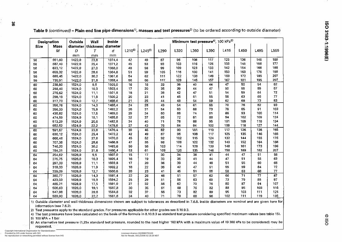
Table 9 (continued) - Plain-end line pipe dimensions’), masses and test pressures2) (to be ordered according to outside diameter)
Designation Outside Wall Inside Minimum test pressure4! 100 kPa5) Size Mass diameter thickness diameter
M D T d L2106) L245(j) L290 L320 L360 L390 L415 L450 L485 L555 m m m m m m
56 551,60 1422,0 23,8 1374,4 42 49 87 96 108 117 125 136 146 166 56 587,40 1422,0 25,4 1371,2 45 53 93 103 116 125 133 145 156 177 56 623,12 1422,0 27,0 1368,0 48 56 99 109 123 133 142 154 166 188 56 659.32 1422,0 28,6 1364,8 51 59 105 116 130 141 150 163 176 199 56 695,45 1422,0 30,2 1361.6 54 62 111 122 138 149 159 172 185 207 56 730,91 1422,0 31,8 1358,4 56 66 117 129 145 157 167 181 195 207 60 238,80 1524,0 92 1505,o 16 18 33 36 40 44 47 50 54 62 60 258,40 1524,0 10.3 1503,4 17 20 35 39 44 47 50 55 59 67 60 278,62 1524,0 II,1 1501,8 18 21 38 42 47 51 54 59 64 72 60 298,19 1524,0 11,9 1500,2 20 23 41 45 51 55 58 63 68 77 60 317,73 1524,0 12,7 1498,6 21 25 44 48 54 59 62 68 73 83 60 356,76 1524,0 14,3 1495,4 24 28 49 54 61 66 70 76 82 93 60 396,33 1524,0 15,9 1492,2 26 31 54 60 68 73 78 85 91 103 60 435,82 1524,0 17,5 1489,0 29 34 60 66 74 81 86 93 100 114 60 474,59 1524,0 19,l 1485,8 32 37 65 72 81 88 94 102 109 124 60 513,29 1524,0 20,6 1482,8 34 40 71 78 88 95 101 109 118 134 60 552,52 1524,0 22,2 1479,6 37 43 76 84 94 102 109 118 127 144 60 591,67 1524.0 23,8 1476,4 39 48 82 90 101 110 117 126 136 155 60 630,12 1524,0 25,4 1473,2 42 49 87 96 108 117 125 135 146 165 60 668,48 1524,0 27,0 1470,o 45 52 92 102 115 124 132 144 155 175 60 707,38 1524,0 28,6 1466,8 47 55 98 108 122 132 140 152 164 186 60 746,20 1524,0 30,2 1463,6 50 58 103 114 128 139 148 161 173 196 60 784,31 1524,0 31,8 1460,4 53 61 109 120 135 146 156 169 182 207 64 254,82 1626,0 93 1607,O 15 17 30 34 38 41 44 47 51 58 64 275,75 1626,0 IO,3 1605,4 16 19 33 36 41 44 47 51 55 63 64 297.33 1626,0 II,1 1603,8 17 20 36 39 44 48 51 55 60 68 64 318,33 1626,0 II,9 1602,2 18 22 38 42 47 51 55 59 64 72 64 339,09 1626,0 12,7 1600,6 20 23 41 45 51 55 58 63 68 77 64 380,77 1626,0 14,3 1597,4 22 26 46 51 57 62 66 71 77 87 64 423,03 1626,0 15,9 1594.2 25 29 51 56 63 69 73 79 85 97 64 465,21 1626,0 17,5 1591,0 27 32 56 62 70 76 80 87 94 107 64 506.63 1626,0 19,l 1587,8 30 35 61 68 76 82 88 95 103 116 64 547,98 1626,0 20,6 1584.8 32 37 66 73 82 89 95 103 111 125 64 589.90 1626,0 22,2 1581,6 34 40 71 79 88 96 102 111 119 135
I) Outside diameter and wall thickness dimensions shown are subject to tolerances as described in 7.6.8. inside diameters are nominal and are given here fo information (see7.6.2).
!) Test pressures applytothe standard grades. For pressures applicable for other grades see 8.10.9.3. I) Thetestpressures have been calculated on the basis ofthe formula in 8.10.9.3 as standardtestpressure considering specified maximum values (see table 15). i) lOOkPA=l bar ;) An alternative test pressure (1,25x standard test pressure, roundedtothe next higher 100 kPA with a maximum value of 19 300 kPato be considered) may bc
requested.
~ , - - 7 r ) - ~ - . - - . - - . - _ -_ - - - . - - . ~~~~1~ ._ __ - . . . . - .__~__. - . - ~ - ; - . - . __
Copyright International Organization for Standardization Provided by IHS under license with ISO Licensee=Aramco HQ/9980755100
Not for Resale, 04/12/2006 02:18:28 MDTNo reproduction or networking permitted without license from IHS
--``,,`,```````,`````,,,,,,`,`,-`-`,,`,,`,`,,`---
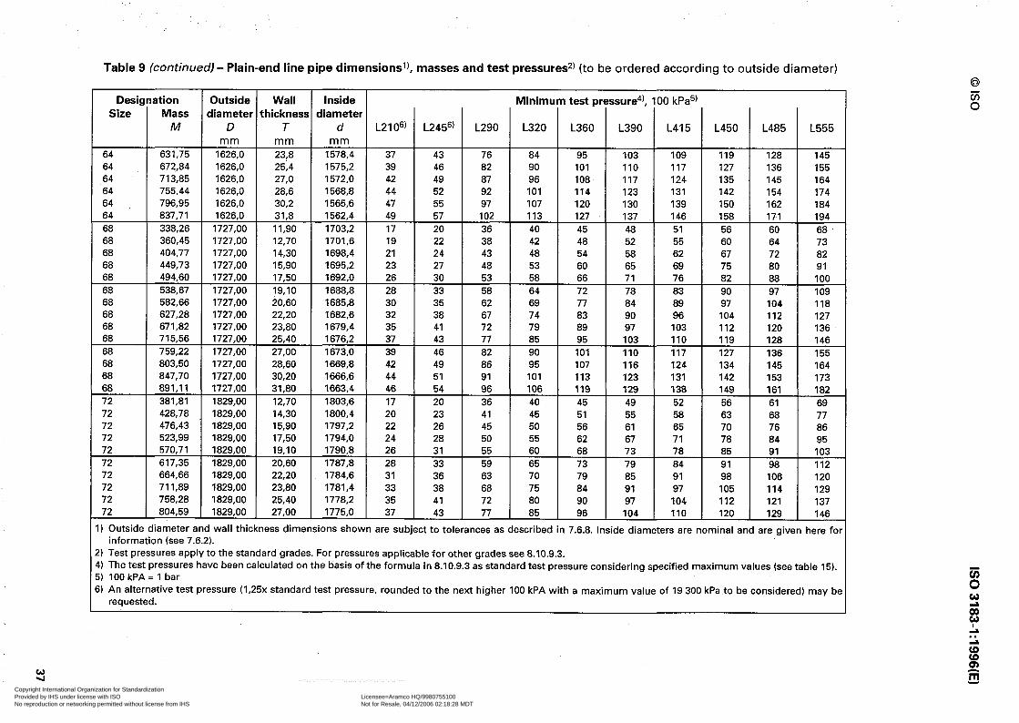
Table 9 (continued) - Plain-end line pipe dimensionsl), masses and test pressures*) (to be ordered according to outside diameter)
Designation Outside Wall inside Minimum test pressure4), 100 kPa5) Size Mass diameter thickness diameter
M D T d L2106’ L2456’ L290 L320 L360 L390 L415 L450 L485 L555 mm mm mm
64 631,75 1626,0 23,8 1578,4 37 43 76 84 95 103 109 119 128 145 64 672,84 1626,0 25,4 1575,2 39 46 82 90 101 110 117 127 136 155 64 713,85 1626,0 27,0 1572,0 42 49 87 96 108 117 124 135 145 164 64 755,44 1626,0 28,6 1568,8 44 52 92 101 114 123 131 142 154 174 64 796,95 1626,0 30,2 1565,6 47 55 97 107 120 130 139 150 162 184 64 837,71 1626,0 31,8 1562,4 49 57 102 113 127 137 146 158 171 194 68 338,26 1727.00 11.90 1703,2 17 20 36 40 45 48 51 56 60 68 68 360,45 1727,00 12,70 1701,6 19 22 38 42 48 52 55 60 64 73 68 404,77 1727,00 14,30 1698,4 21 24 43 48 54 58 62 67 72 82 68 449,73 1727,00 15,90 1695,2 23 27 48 53 60 65 69 75 80 91 68 494,60 1727,00 17,50 1692.0 26 30 53 58 66 71 76 82 88 100 68 538,67 1727,00 19,lO 1688,8 28 33 58 64 72 78 83 90 97 109 68 582,66 1727,00 20,60 1685,8 30 35 62 69 77 84 89 97 104 118 68 627.28 1727.00 22,20 1682,6 32 38 67 74 83 90 96 104 112 127 68 671,82 1727,00 23,80 1679,4 35 41 72 79 89 97 103 112 120 136 68 715,56 1727,00 25.40 1676,2 37 43 77 85 95 103 110 119 128 146 68 759,22 1727,00 27,00 1673,0 39 46 82 90 101 110 117 127 136 155 68 803,50 1727,00 28,60 1669.8 42 49 86 95 107 116 124 134 145 164 68 847,70 1727,00 30,20 1666,6 44 51 91 101 113 123 131 142 153 173 68 891,ll 1727,OO 31,80 1663,4 46 54 96 106 119 129 138 149 161 182 72 381,81 1829,00 12,70 1803.6 17 20 36 40 45 49 52 56 61 69 72 428.78 1829.00 14,30 1800,4 20 23 41 45 51 55 58 63 68 77 72 476,43 1829.00 15,90 1797.2 22 26 45 50 56 61 65 70 76 86 72 523,99 1829.00 17,50 1794,0 24 28 50 55 62 67 71 78 84 95 72 570,71 1829.00 19,lO 1790,8 26 31 55 60 68 73 78 85 91 103 72 617,35 1829,00 20,60 1787.8 28 33 59 65 73 79 84 91 98 112 72 664,66 1829,00 22,20 1784,6 31 36 63 70 79 85 91 98 106 120 72 711,89 1829,00 23,80 1781.4 33 38 68 75 84 91 97 105 114 129 72 758.28 1829,00 25,40 1778.2 35 41 72 80 90 97 104 112 121 137 72 804,59 1829,00 27,00 1775,0 37 43 77 85 96 104 110 120 129 146
I) Outside diameter and wall thickness dimensions shown are subject to tolerances as described in 7.6.8. Inside diameters are nominal and are given here for information (see7.6.2).
!) Test pressures applytothe standard grades.Forpressures applicableforothergradessee8.10.9.3. I) The test pressures have been calculated on the basis of the formula in 8.10.9.3 as standard test pressure considering specified maximum values (see table 15). 5) lOOkPA= 1 bar i) An alternative test pressure (1,25x standard test pressure, roundedtothe next higher 100 kPA with a maximum value of 19 300 kPa to be considered) may be
requested.
Y Copyright International Organization for Standardization Provided by IHS under license with ISO Licensee=Aramco HQ/9980755100
Not for Resale, 04/12/2006 02:18:28 MDTNo reproduction or networking permitted without license from IHS
--``,,`,```````,`````,,,,,,`,`,-`-`,,`,,`,`,,`---

IS0 3183-1:1996(E) 0 IS0
c al z s .- -0 42 .- 3 2 0
E .- ‘El 0
8
z iii
E 0
$ 0
z si 8 5
% i;
x d ‘El
f ul % t E
-9 -in
E z
s E
z
.: P
E ”
Z ? E .-
m Q
I
s
5
E
8
Q, 1
9 I-
E
i 8 ‘E
2 8%
gwmt-N!- I- ,me-e*w
E
+-
0
!
NWT-brnrnr-h cowmm)c)~-fLc
6 s wmt-mN*bm rl **wrNNNw
I I
pp: ;
t S&,E q ‘9 t ‘9 t n! 9 o? ‘f f
rww*-wwr bwwoommm Ebbf-mmaJoJm - .- cr-rrcr77
u
= 8 00000000 m c L E ‘9 N, aa Y ? Q! LD. ‘: %E EwOrN-tw~ffl Np-Jmrrrrr
5 L
L!g 00000000 00000000 3 EQ E
Is oj 6 d d 0’ 0‘ d =lu NNNmmmmm wwwmmmmm 3% ~~~r-~~~
.- a$
ww*Noww**Nowww*Noww* m: m’ N’ 6 cd N’ G cd pj d r-: c-4 0: r; & ,’ ao’ 4 ; cd wwwbbbwwoommmWWW~i-r-W wwwwwwwwoomm~mmmmmmm I-FrrrrrrNNrr 7FcrFccr
00000000000000000000 wr4w*owr4wmmws-wNw*owr4w 0‘ N’ 05 m’ IQ aj 0’ G d d I; 6 d ru‘ Fi d I-Z 125 d G NNNNNNmmr~rrNNNNNNmm
00000000000000000000 9 9 9 9 9 9 9 9 9 9 9 9 9 9 9 9 9 9 9 9 00000000NNNNNNNNNNNN mmommmmmmmmmm~mmmmmm mmmmmmmmoooooooooooo r-r--rrrrNNNNNNNNNNNN
8 u- p! 2
!z ‘6
f
2 ro 5 .E E E
s
s % E 0 5 al 0 ii c6 cd r-: .5 B P b $ u : I 2 2 s 8 s H 3 iz
f
$ z ii 2 i? E b I E ‘5 E a- = (D
is c “, a B ti s
! 7 E i ‘Z ii x b- .- 8 E: P ‘C a2 0 E 8 ?I z
CTjE ojh $Z OjB UE I+.j $= 02 FW 0-J: taq 50! 00 5: 2 .E $2 .o E’ EL g-” u)a 25 Z% z .I? h2 LP OQ) u1s $c -00 2-J 08 E; 4” =E Qg &2 _.
2 z E fi E 2 E 8 2 s
k
E 2 % zi P E z R z 0 AZ .Y 3 a B 8
is c .P 2z
%
z B -0 G 5 2 E! z I k x B E 4 5 w X
q T s! i? 1 h
3 ,gs 2 ~cljkc ,I-:gm $i a,allJE %a EVIti?
=g zo $i
*m_ c 2 $! F ‘S U.“~rlII Ed ati;oxaLS UEhaCL82 .E&&yo”g l3~~~~~ e
38 Copyright International Organization for Standardization Provided by IHS under license with ISO Licensee=Aramco HQ/9980755100
Not for Resale, 04/12/2006 02:18:28 MDTNo reproduction or networking permitted without license from IHS
--``,,`,```````,`````,,,,,,`,`,-`-`,,`,,`,`,,`---

0 IS0 IS0 3183-1:1996(E)
7.6.8 Tolerances on dimensions and masses
7.6.8.1 Outside diameter D
The outside diameter tolerances shall be as follows:
Pipe body I48,3 mm . . . . . . . . . . . . . ..*........................................................................*....................*................. + 0,41 mm
- 0,79 mm
60,3 mm to 114,3 mm grade L175, butt-weld only . . . . . . . . . . . . . . . . . . . . . . . . . . . . . . . . . . . . . . . . . . . . . . . . . . . . . . . . . . . . . . + I,00 %
60,3 mm to 457,0 mm . . . . . . . . . . . . . . . . . . . . . . . . . . . . . . . . . . . . . . . . . . . . . . . . . . . . . . . . . . . . . . . . . . . . . . . . . . . . . . . . . . . . . . . . . . . . . . . . . . . . . . . . . . . . . + 0,75 %
508,O mm to 914,0 mm Non-expanded *......................................................................*.......................................... + I,00 % Cold expanded . . . . . . . . . . . . . . . . . . . . . . . . . . . . . . . . . . . . . . . . . . . . . . . . . . . . . . . ..~........................................................ + 0,75 %
- 0,25 %
> 914,0 mm Non-expanded . . . . . . . . . . . . . . . . . . . . . . . . . . . . . . . . . . . . . . . . . . . . . . . . . . . . . . . . . . . . . . . . . . . . . . . . . . . . . . . . . . . . . . . . . . . . . . . . . . . . . . . . . . . . . . . . . . + I,00 % Cold expanded . . . . . . . . . . . . . . . . . . . . . . . . . . . . . . . . . . . . . . . . . . . . . . . . . . . . . . . . . . . . . . . . . . . . . . . . . . . . . . . . . . . . . . . . . . . . . . . . . . . . . . . . . . . . . . . . . . + 6,35 mm
- 3,20 mm
NOTE 6 In the case of cold expanded pipe outside diameter > 914,0 mm hydrostatically tested to pressures in excess of standard test pressures, other tolerances may be agreed upon between manufacturer and purchaser.
7.6.8.2 Pipe ends
For a distance of 101,6 mm from the end of the pipe, pipe outside diameters I273,l mm shall not be more than 0,40 mm smaller than the specified outside diameter and shall permit the passage, over the ends, of a ring gauge which has a bore I,59 mm larger than the specified outside diameter of the pipe.
For a distance of 101,6 mm from the end of the pipe, pipe outside diameters between 323,9 mm and 508,O mm inclusive, shall not be more than 0,79 mm smaller than the specified outside diameter and shall permit the passage, over the ends, of a ring gauge which has a bore 2,38 mm larger than the specified outside diameter of the pipe.
For pipe with filler metal welds, it shall be permissible to notch or slot the ring gauge to permit the passage of the gauge over the weld bead.
At the option of the manufacturer, minimum pipe outside diameters I508,O mm may be measured with a diameter tape.
For a distance of 101,6 mm from the end of the pipe, pipe outside diameters > 508,O mm shall be neither more than 0,79 mm smaller nor more than 2,38 mm larger than the specified outside diameter, as measured with a diameter tape.
By agreement between the interested parties, at the ends the tolerance on outside diameter may be applied instead to the inside diameter.
On welded expanded pipe with outside diameters > 508,O mm the diameter, measured at one end of the pipe with a diameter tape, shall not differ by more than 2,38 mm from that of the other end. At the manufacturer’s option, these measurements may be made on the inside diameter.
39 Copyright International Organization for Standardization Provided by IHS under license with ISO Licensee=Aramco HQ/9980755100
Not for Resale, 04/12/2006 02:18:28 MDTNo reproduction or networking permitted without license from IHS
--``,,`,```````,`````,,,,,,`,`,-`-`,,`,,`,`,,`---
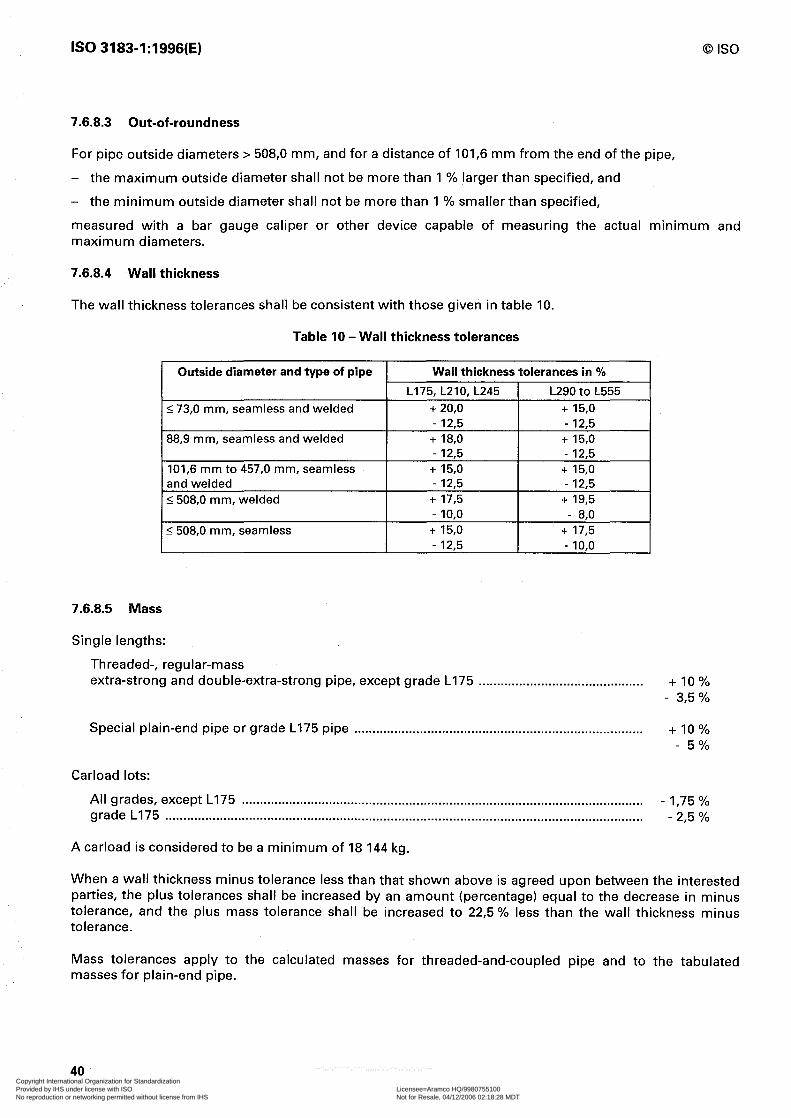
IS0 3183-1:1996(E) 0 IS0
7.6.8.3 Out-of-roundness
For pipe outside diameters > 508,O mm, and for a distance of 101,6 mm from the end of the pipe,
- the maximum outside diameter shall not be more than 1 % larger than specified, and
- the minimum outside diameter shall not be more than 1 % smaller than specified,
measured with a bar gauge caliper or other device capable of measuring the actual minimum and maximum diameters.
7.6.8.4 Wall thickness
The wall thickness tolerances shall be consistent with those given in table 10.
Table 10 -Wall thickness tolerances
Outside diameter and type of pipe Wall thickness tolerances in %
L175.L21O,L245 1 L290to L555 1 I 73,0 mm, seamless and welded I + 20,o I + 15,0 I
88,9 mm, seamless and welded + 18,0 + 15,0 - 12,5 - 12,5
101,6 mm to 457,0 mm, seamless -I- 15,0 + 15,0 and welded - 12,5 - 12,5 I508,O mm, welded + 17,5 + 19,5
- 10.0 - 8.0
I 5 508,O mm, seamless I
+ 15,0 + 17,5 - 12.5 I - 10.0 I
7.6.8.5 Mass
Single lengths:
Threaded-, regular-mass extra-strong and double-extra-strong pipe, except grade L175 . . . . . . . . . . . . . . . . . . . . . . . . . . . . . . . . . . . . . . . . . . . . . + 10%
- 3,5 %
Special plain-end pipe or grade L175 pipe . . . . . . . . . . . . . . . . . . . . . . . . . . . . . . . . . . . . . . . . . . . . . . . . . . . . . . . . . . . . . . . . . . . . . . . . . . . . . . . + 10% - 5%
Carload lots:
All grades, except L175 . . . . . . . . . . . . . . . . . . . . . . . . . . . . . . . . . . . . . . . . . . . . . . . . . . . . . . . . . . . . . . . . . . . . . . . . . . . . . . . . . . . . . . . . . . . . . . . . . . . . . . . . . . . . . . - I,75 % grade L175 . . . . . . . . . . . . . . . . . . . . . . . . . . . . . . . . . . . . . . . . . . . . . . . . . . . . . . . . . . . . . . . . . . . . . . . . . . . . . . . . . . . . . . . . . . . . . . . . . . . . . . . . . . . . . . . . . . . . . . . . ........... - 2,5 %
A carload is considered to be a minimum of 18 144 kg.
When a wall thickness minus tolerance less than that shown above is agreed upon between the interested parties, the plus tolerances shall be increased by an amount (percentage) equal to the decrease in minus tolerance, and the plus mass tolerance shall be increased to 22,5 % less than the wall thickness minus tolerance.
Mass tolerances apply to the calculated masses for threaded-and-coupled pipe and to the tabulated masses for plain-end pipe.
40
i
Copyright International Organization for Standardization Provided by IHS under license with ISO Licensee=Aramco HQ/9980755100
Not for Resale, 04/12/2006 02:18:28 MDTNo reproduction or networking permitted without license from IHS
--``,,`,```````,`````,,,,,,`,`,-`-`,,`,,`,`,,`---
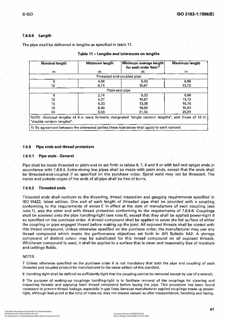
0 IS0 IS0 3183-1:1996(E)
7.6.8.6 Length
The pipe shall be delivered in lengths as specified in table 11.
Table II- Lengths and tolerances on lengths
Nominal length Minimum length Minimum average length Maximum length for each order item’)
m m m m Threaded-and-coupled pipe
6 4,88 5,33 6,86 12 6,71 IO,67 13,72
Plain-end pipe 6 2,74 5.33 6,86
12 4,27 IO,67 13,72 15 5,33 13,35 16,76 18 6,40 16,00 19,81 24 8,53 21,34 25,91
NOTE - Nominal lengths of 6 m were formerly designated “single random lengths”, and those of 12 m “double random lenaths”.
1) By agreement between the interested parties these tolerances shall apply to each carload.
7.6.9 Pipe ends and thread protectors
7.6.9.1 Pipe ends - General
Pipe shall be made threaded or plain-end as set forth in tables 6, 7, 8 and 9 or with bell and spigot ends in accordance with 7.6.9.4. Extra-strong line pipes shall be made with plain ends, except that the ends shall be threaded-and-coupled if so specified on the purchase order. Spiral weld may not be threaded. The inside and outside edges of the ends of all pipe shall be free of burrs.
7.6.9.2 Threaded ends
Threaded ends shall conform to the threading, thread inspection and gauging requirements specified in IS0 10422, latest edition. One end of each length of threaded pipe shall be provided with a coupling conforming to the requirements of annex C in effect at the date of manufacture of each coupling (see note 71, and the other end with thread protection conforming to the requirements of 7.6.9.6. Couplings shall be screwed onto the pipe handling-tight (see note 81, except that they shall be applied power-tight if so specified on the purchase order. A thread compound shall be applied to cover the full surface of either the coupling or pipe engaged thread before making up the joint. All exposed threads shall be coated with this thread compound. Unless otherwise specified on the purchase order, the manufacturer may use any thread compound which meets the performance objectives set forth in API Bulletin 5A2. A storage compound of distinct colour may be substituted for this thread compound on all exposed threads. Whichever compound is used, it shall be applied to a surface that is clean and reasonably free of moisture and cuttings fluids.
NOTES
7 Unless otherwise specified on the purchase order it is not mandatory that both the pipe and coupling of each threaded and coupled product be manufactured to the same edition of this standard.
8 Handling tight shall be defined as sufficiently tight that the coupling cannot be removed except by use of a wrench.
9 The purpose of making-up couplings handling-tight is to facilitate removal of the couplings for cleaning and inspecting threads and applying fresh thread compound before laying the pipe. This procedure has been found necessary to prevent thread leakage, especially in gas lines, because manufacturer applied couplings made up power- tight, although leak-proof at the time of make-up, may not always remain so after transportation, handling and laying.
41 Copyright International Organization for Standardization Provided by IHS under license with ISO Licensee=Aramco HQ/9980755100
Not for Resale, 04/12/2006 02:18:28 MDTNo reproduction or networking permitted without license from IHS
--``,,`,```````,`````,,,,,,`,`,-`-`,,`,,`,`,,`---
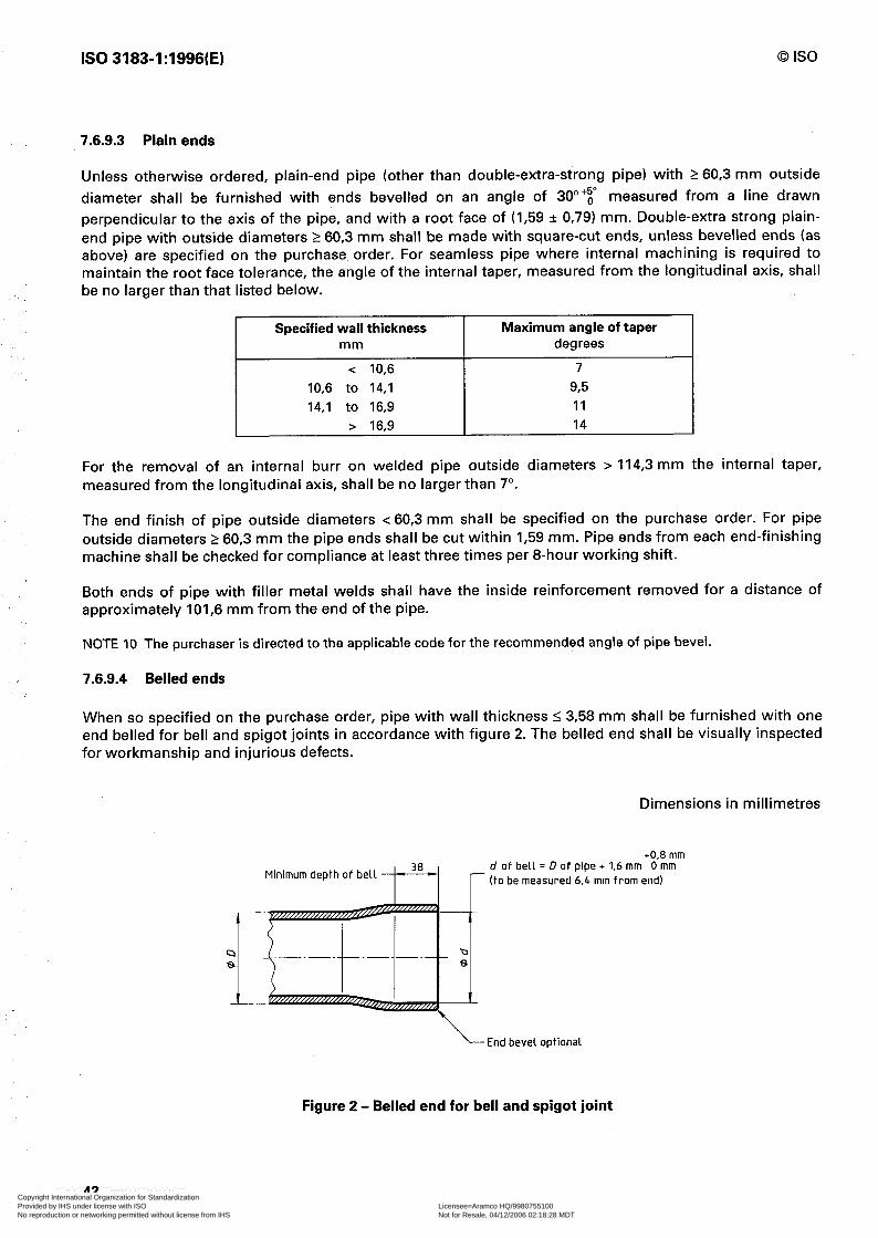
IS0 3183-1:1996(E) 0 IS0
7.6.9.3 Plain ends
Unless otherwise ordered, plain-end pipe (other than double-extra-strong pipe) with 2 60,3 mm outside diameter shall be furnished with ends bevelled on an angle of 30”‘: measured from a line drawn perpendicular to the axis of the pipe, and with a root face of (I,59 f 0,79) mm. Double-extra strong plain- end pipe with outside diameters 2 60,3 mm shall be made with square-cut ends, unless bevelled ends (as above) are specified on the purchase order. For seamless pipe where internal machining is required to maintain the root face tolerance, the angle of the internal taper, measured from the longitudinal axis, shall be no larger than that listed below.
Specified wall thickness Maximum angle of taper mm degrees
< IO,6 7 IO,6 to 14,l 93 14,l to 16,9 11
> 16,9 14
For the removal of an internal burr on welded pipe outside diameters > 114,3 mm the internal taper, measured from the longitudinal axis, shall be no larger than 7”.
The end finish of pipe outside diameters < 60,3 mm shall be specified on the purchase order. For pipe outside diameters 2 60,3 mm the pipe ends shall be cut within I,59 mm. Pipe ends from each end-finishing machine shall be checked for compliance at least three times per 8-hour working shift.
Both ends of pipe with filler metal welds shall have the inside reinforcement removed for a distance of approximately 101,6 mm from the end of the pipe.
NOTE 10 The purchaser is directed to the applicable code for the recommended angle of pipe bevel.
7.6.9.4 Belled ends
When so specified on the purchase order, pipe with wall thickness 5 3,58 mm shall be furnished with one end belled for bell and spigot joints in accordance with figure 2. The belled end shall be visually inspected for workmanship and injurious defects.
Dimensions in millimetres
+0,8 mm
Minimum depth of bell d of bell = D of pipe + 1.6 mm 0 mm (to be measured 6.4 mm from end)
L End bevel optional
Figure 2 - Belled end for bell and spigot joint
Copyright International Organization for Standardization Provided by IHS under license with ISO Licensee=Aramco HQ/9980755100
Not for Resale, 04/12/2006 02:18:28 MDTNo reproduction or networking permitted without license from IHS
--``,,`,```````,`````,,,,,,`,`,-`-`,,`,,`,`,,`---

0 IS0 IS0 3183-1:1996(E)
7.6.9.5 Plain ends for special couplings
When so specified on the purchase order, pipe shall be made with ends suitable for use with special couplings (see note 11). Such pipe shall be sufficiently free from indentations, projections, or roll marks for a distance of 203 mm from the end of the pipe, to permit proper make-up coupling.
Note 11 Dresser and Victaulic are examples for suitable products available commercially. This information is given for the convenience of the user of this part of IS0 3183 and does not constitute an endorsement by IS0 of these products.
7.6.9.6 Thread protectors
On nominal pipe sizes smaller than 2, the thread protectors shall be suitable fabric wrappings, or suitable metal, fiber, or plastic protectors. On nominal pipe sizes 2 and larger, the thread protectors shall be of such design, material, and mechanical strength to protect the thread and end of the pipe from damage under normal handling and transportation. The thread protectors shall cover the full length of the thread on the pipe and exclude water and dirt from the thread during transportation and normal storage period. Normal storage period shall be considered as approximately one year. The thread formed in protectors shall be such that the pipe threads are not damaged by the protectors. Protector material shall contain no compounds capable of causing corrosion or promoting adherence of the protectors to the threads and shall be suitable for service temperatures of -46 “C to +66 “C.
8 Testing and inspection
8.1 Type of documents on inspection and testing
8.1.1 General
Upon request by the purchaser, the manufacturer shall provide a document of compliance stating that the material has been manufactured, sampled, tested and inspected in accordance with this part of IS0 3183 and has been found to meet the requirements.
Where additional information is required, including the results of mechanical testing, SR6 (see annex D) or one of the inspection documents of IS0 10474 shall be specified on the purchase order.
8.1.2 Test reports on chemical analysis
The results of all specified chemical analysis shall be available to the purchaser upon request. When SR6 is specified by the purchaser (see annex D), a report containing all chemical analyses required by this specification shall be provided by the manufacturer.
For grade L175, in place of the test report, the manufacturer may certify that the pipe delivered was produced in conformity with the requirements for chemical properties and tests of this part of IS0 3183.
8.2 Purchaser inspection
For the purchaser’s inspection see annex F.
8.3 Retention of records
Tests and inspections requiring retention of records in this part of IS0 3183 are shown in table 12. Such records shall be retained by the manufacturer and shall be made available to the purchaser upon request for a period of three years after the date of purchase from the manufacturer.
43 Copyright International Organization for Standardization Provided by IHS under license with ISO Licensee=Aramco HQ/9980755100
Not for Resale, 04/12/2006 02:18:28 MDTNo reproduction or networking permitted without license from IHS
--``,,`,```````,`````,,,,,,`,`,-`-`,,`,,`,`,,`---

IS0 3183-1:1996(E) 0 IS0
Table 12 - Retention of records
Requirement Chemical composition
Cast analysis Product analysis
Mechanical tests Tensile tests Weld tensile tests Mill control tests Guided bend tests Fracture toughness tests
Hydrostatic tests Tester recorder charts (where used) Supplementary hydrostatic tests
Non-destructive inspection Film (where used) Fluoroscopic operator qualifications
Welded jointers Film
Repair welding procedure Transverse tensile test Transverse guided bend test Nick break test Procedure specification Procedure qualification Personnel performance qualification
Calibration tests
Reference 7.2 8.4.2 8.4.3 8.5 8.5.1.1 8.5.1.1 8.5.1.1 8.5.1.4 8.5.1,6, SR3, SR4 8.6 8.10.9.2 8.10.9.4 8.9 8.10.11.1 8.10.11.2.2
A.4
B.2.2.2 8.2.2.3 B.2.2.4 B.l 8.2 8.3 various paragraphs
8.4 Testing of chemical composition
8.4.1 Elements analysed
As a minimum, each required analysis shall include the determination of carbon, manganese, phosphorus, sulfur and silicon; niobium, vanadium, titanium, or combinations thereof, if added during steelmaking; and any other alloying element added during steelmaking for other than deoxidation purpose.
8.4.2 Cast analysis
The steel manufacturer shall determine the analysis of each cast of steel used in the manufacture of pipe specified on the purchase order. The analysis so determined shall conform to the requirements of 7.2.1.
For grade L555, cast analysis limits have not been defined, only product analysis limits.
8.4.3 Product analysis
8.4.3.1 Sampling frequency
The manufacturer shall determine the analysis of two samples representing each cast of steel used for the production of pipe under this part of IS0 3183.
8.4.3.2 Sampling methods
Seamless pipe At the option of the manufacturer, samples used for product analysis shall be taken either from tensile test specimens or from the finished pipe.
! I ! / I
I i
! i,
t I I
[ 4
I 1 $, I
i; 1 1: :’ i I
/ / I, ! [ / I
I
j
I I
I i. 1 I i [
44 Copyright International Organization for Standardization Provided by IHS under license with ISO Licensee=Aramco HQ/9980755100
Not for Resale, 04/12/2006 02:18:28 MDTNo reproduction or networking permitted without license from IHS
--``,,`,```````,`````,,,,,,`,`,-`-`,,`,,`,`,,`---
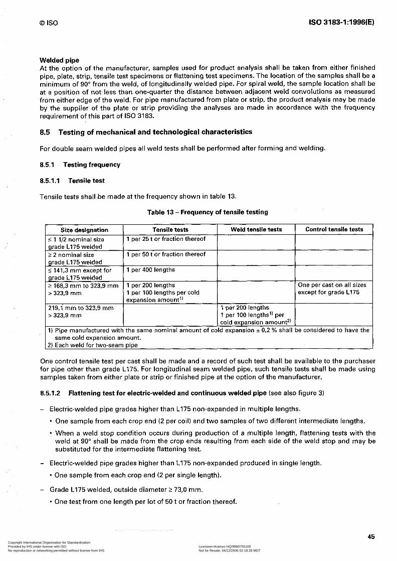
0 IS0 IS0 3183-1:1996(E)
Welded pipe At the option of the manufacturer, samples used for product analysis shall be taken from either finished pipe, plate, strip, tensile test specimens or flattening test specimens. The location of the samples shall be a minimum of 90” from the weld, of longitudinally welded pipe. For spiral weld, the sample location shall be at a position of not less than one-quarter the distance between adjacent weld convolutions as measured from either edge of the weld. For pipe manufactured from plate or strip, the product analysis may be made by the supplier of the plate or strip providing the analyses are made in accordance with the frequency requirement of this part of IS0 3183.
8.5 Testing of mechanical and technological characteristics
For double seam welded pipes all weld tests shall be performed after forming and welding.
8.5.1 Testing frequency
851.1 Tensile test
Tensile tests shall be made at the frequency shown in table 13.
Table 13 - Frequency of tensile testing
Size designation 5 1 112 nominal size grade L175 welded 2 2 nominal size grade L175 welded I 141,3 mm except for grade L175 welded 2 168,3 mm to 323,9 mm > 323,9 mm
Tensile tests I Weld tensile tests 1 per 25 t or fraction thereof
1 per 50 t or fraction thereof
1 per 400 lengths
1 per 200 lengths 1 per 100 lengths cold per expansion amount’)
219,l mm to 323,9 mm I 1 per 200 lengths > 323,9 mm 1 per 100 lengths’) per
I cold expansion amount*) 1) Pipe manufactured with the same nominal amount of cold expansion + 0,2 % shall
same cold expansion amount. 2) Each weld for two-seam pipe
38 considered to have the
Control tensile tests /
One control tensile test per cast shall be made and a record of such test shall be available to the purchaser for pipe other than grade Ll75. For longitudinal seam welded pipe, such tensile tests shall be made using samples taken from either plate or strip or finished pipe at the option of the manufacturer.
851.2 Flattening test for electric-welded and continuous welded pipe (see also figure 3)
- Electric-welded pipe grades higher than L175 non-expanded in multiple lengths.
l One sample from each crop end (2 per coil) and two samples of two different intermediate lengths.
l When a weld stop condition occurs during production of a multiple length, flattening tests with the weld at 90” shall be made from the crop ends resulting from each side of the weld stop and may be substituted for the intermediate flattening test.
- Electric-welded pipe grades higher than L175 non-expanded produced in single length.
l One sample from each crop end (2 per single length).
- Grade L175 welded, outside diameter 2 73,0 mm.
l One test from one length per lot of 50 t or fraction thereof.
45 Copyright International Organization for Standardization Provided by IHS under license with ISO Licensee=Aramco HQ/9980755100
Not for Resale, 04/12/2006 02:18:28 MDTNo reproduction or networking permitted without license from IHS
--``,,`,```````,`````,,,,,,`,`,-`-`,,`,,`,`,,`---
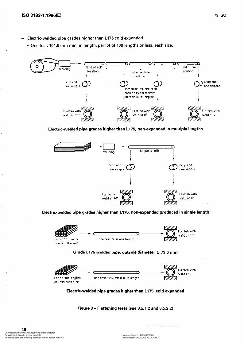
IS0 3183-1:1996(E) 0 IS0
- Electric-welded pipe grades higher than L175 cold expanded.
l One test, 101,6 mm min. in length, per lot of 100 lengths or less, each size.
Intermediate
Crop end CD CD CD CD
Crop end one sample one sample
I 1
Two samples, one from each of two different intermediate lengths
I 1
Flatten with weld at 90’
Flatten with weld at 0’
Flatten with weld at 90”
Electric-welded pipe grades higher than L175, non-expanded in multiple lengths
Crop end CD CD
Crop end one sample one sample
46
Flatten with weld at 90”
Flatten with weld at 0’
Electric-welded pipe grades higher than L175, non-expanded produced in single length
-- Lot of 50 tons or One test from one length fraction thereof
Grade L175 welded pipe, outside diameter 2 73,0 mm
-P Lot of 100 lengths One test 101.6 mm min. in length
Flatten with weld at 90’
or less each size
Electric-welded pipe grades higher than L175, cold expanded
Figure 3 - Flattening tests (see 8.5.1.2 and 8.5.2.2)
Copyright International Organization for Standardization Provided by IHS under license with ISO Licensee=Aramco HQ/9980755100
Not for Resale, 04/12/2006 02:18:28 MDTNo reproduction or networking permitted without license from IHS
--``,,`,```````,`````,,,,,,`,`,-`-`,,`,,`,`,,`---

0 IS0 IS0 3183-1:1996(E)
8.5.1.3 Bend test
Bend tests are applied for welded grade L175 pipe of nominal size 2 and smaller with a frequency of
- one test per 25 t or fraction thereof, nominal size 1 l/2 and smaller
and
-one test per 50 t, or fraction thereof, for pipe of nominal size 2.
8.5.1.4 Manipulation tests for submerged arc- and gas metal arc-welds
Submerged arc- and gas metal arc-welded pipe shall be tested by the guided-bend test.
Two test specimens shall be taken from the helical or each longitudinal seam weld in a length of pipe from each lot of 50 lengths or less of each combination of outside diameter, wall thickness, and grade; and from a strip end weld in length of pipe from each lot of 50 lengths or less of each combination of outside diameter wall thickness, and grade of finished helical seam pipe containing strip end welds.
8.5.1.5 Weld ductility test
For electric-welded pipe one test shall be made on a length of pipe from each lot size as indicated in table 14.
Table 14 - Test frequency for electric-welded pipe
Grade
L175, L210 and L245 L175, L210 and L245 L290 and hinher
1 All grades
Outside diameter Lot size mm No. of lengths
60,3 to 141,3 400 or less
168,3 to 323,9 200 or less
60,3 to 323,9 200 or less
1355.6 100 or less I
For multiple-length pipe, a length shall be considered as each section cut from a particular multiple length.
The weld ductility test may also serve as one of the flattening tests of 8.5.1.2 by compliance with appropriate amounts of flattening.
8.5.1.6 Fracture toughness tests
(Lot size, see SR3 and SR4 in annex D.)
8.5.1.6.1 For grade L555 three specimens representing one test shall be taken
- from one length of pipe from each cast for determining the shear area,
- from each lot for determining the absorbed energy.
8.5.1.6.2 For grade L555 three specimens shall be taken from one length of pipe from each cast supplied in the order for drop weight tear testing on welded pipe of all diameters.
8.5.1.7 Metallographic examination
Such examinations shall be performed at least once per working turn, or more frequently where grade, diameter, or wall thickness changes are made, or where significant excursions from operating heat- treatment conditions are encountered for the grades covered in 7.4.
47 Copyright International Organization for Standardization Provided by IHS under license with ISO Licensee=Aramco HQ/9980755100
Not for Resale, 04/12/2006 02:18:28 MDTNo reproduction or networking permitted without license from IHS
--``,,`,```````,`````,,,,,,`,`,-`-`,,`,,`,`,,`---

IS0 3183-1:1996(E) 0 IS0
8.5.2 Location and orientation of test pieces for mechanical and technological tests
8.5.2.1 Tensile test
Tensile test orientation shall be as shown in figure 4. At the option of the manufacturer for longitudinal seam welded pipe, the longitudinal specimens may be taken from the strip parallel to the rolling directions and approximately midway between edge and centre.
Weld tensile test specimens shall be taken at 90” to the weld with the weld at the centre, as shown in figure 4.
Size designation Seamless pipe Welded pipe
Longitudinal seam Helical seam
-z 8 51% & @ Q@
A a A
2 8 51%
& ,8oe& @
C
A = Strip specimen (any circumferential location for seamless). B = Transverse specimen (any circumferential location for seamless). For double seam
pipe the specimen shall be taken from a location midway between the welds. C = Transverse weld specimen.
Figure 4 - Orientation of tensile test specimens
8.5.2.2 Flattening test (see also figure 3)
- Electric-welded pipe grades higher than L175 non-expanded in multiple lengths.
l Specimen with end of coil location to be flattened with weld at 90”.
l Specimen from intermediate locations to be flattened with weld at 0”.
- Electric-welded pipe grades higher than L175 non-expanded produced in single length.
l Samples from the crop end locations to be flattened 50 % of them with a weld position of 0” and 50 % of them with a weld position at 90”.
1 1 f b,
I
F
1
i t
1
j
1
k
a 1
I
k
1. ::
f (’ 1~
1; i-
1.
i
1. /
1.
1
!, i
I i
I
; /
!
I
; /
1,
i 1
48 Copyright International Organization for Standardization Provided by IHS under license with ISO Licensee=Aramco HQ/9980755100
Not for Resale, 04/12/2006 02:18:28 MDTNo reproduction or networking permitted without license from IHS
--``,,`,```````,`````,,,,,,`,`,-`-`,,`,,`,`,,`---

0 IS0 IS0 3183-1:1996(E)
- Cold expanded electric-welded pipe grades higher than L175 and all other welded pipe, in grade L175, outside diameter > 73 mm.
l Samples to be flattened with weld at 90”.
NOTE 12 Flattening tests with the weld at the 0” orientation may be conducted at 180” and the 90” orientation at 270” by agreement between the interested parties.
8.5.2.3 Bend test
A full-section specimen of appropriate length shall be taken for bending.
8.5.2.4 Manipulation tests for submerged arc- and gas metal arc-welds
For the guided-bend test the test specimens one face-bend and one root-bend, both conforming to figure 5, shall be taken from the helical or longitudinal weld and shall not contain repair welds.
8.5.2.5 Weld ductility test
For the weld ductility test a full-section specimen of 50,8 mm minimum length shall be used.
8.5.2.6 Fracture toughness test
The specimens shall be oriented circumferentially from a location 90” from the weld, with the axis of the notch oriented through the pipe wall thickness as shown in figure D.2. For pipe outside diameters I 168,3 mm, longitudinal specimens shall be used.
8.5.2.7 Metallographic examination
The test specimen shall be taken from a weld cross-section.
8.6 Hydrostatic test
Each length of pipe shall withstand, without a leakage, an inspection hydrostatic test to at least the pressure and holding time specified in 8.10.9.
8.7 Dimensional testing and weighing
8.7.1 Consistency with all dimensional and mass requirements shall be ensured by adequate methods as defined in 8.10.10.
8.7.2 For pipe outside diameters 2 114,3 mm the outside diameter measurements on the body of the pipe shall be made on a random basis; there shall not be less than three measurements per 8-hour working turn.
8.7.3 Each length of pipe shall be measured for conformity with wall thickness requirements.
8.7.4 Pipe outside diameters c 114,3 mm in grades L175, L210 and L245 shall be reasonably straight.
All other pipe shall be random checked for conformity with straightness requirements.
49 Copyright International Organization for Standardization Provided by IHS under license with ISO Licensee=Aramco HQ/9980755100
Not for Resale, 04/12/2006 02:18:28 MDTNo reproduction or networking permitted without license from IHS
--``,,`,```````,`````,,,,,,`,`,-`-`,,`,,`,`,,`---

IS0 3183-1:1996(E) 0 IS0
8.8 Visual examination
All pipe shall be visually examined (see annex G).
8.9 Non-destructive testing
Except for grade L175 pipe, the weld seams of welded pipe outside diameters 2 60,3 mm shall be inspected full length (100 %) in accordance with the methods specified in 8.10.11.1. In addition, the strip end weld in finished helical seam pipe shall be so inspected. The location of equipment in the manufacturer’s facility shall be at the discretion of the manufacturer.
By agreement between the interested parties, and when specified on the purchase order, seamless pipes shall be non-destructively tested in accordance with SR2 (annex D).
By agreement between interested parties, and when specified on the purchase order, electric-welds shall be non-destructively tested in accordance with SR7 (annex D).
8.10 Test methods and results
If test equipment, whose calibration or verification is required under the provisions of this part of IS0 3183, is subjected to such unusual or severe conditions that its accuracy would become questionable, recalibration or a new verification shall be performed before further use of the equipment.
8.10.1 Chemical analysis
Methods and practices relating to chemical analysis shall be performed in accordance with ASTM A 751.
The results of chemical analysis shall comply with the requirements in 7.2.
8.10.2 Tensile test
8.10.2.1 General
Testing procedure shall conform to the requirements of the latest edition of IS0 6892 or ASTM A 370, annex II.
The results of the tensile test shall meet the requirements for the steel grade concerned shown in table 3.
8.10.2.1.1 Tensile test machines shall have been calibrated within 15 months preceding any test in accordance with the procedures of ASTM E 4. Where yield strength is determined by the use of extensometers, such extensometers shall be calibrated within the preceding 15 months in accordance with the procedures of ASTM E 83.
8.10.2.1.2 All tensile tests, except transverse weld and ring tests, shall include determination of the yield strength for 0,5 % total elongation (&,,), the ultimate tensile strength (R,,,) and the percentage of elongation after fracture ( A 1 and shall be performed at room temperature.
The percentage elongation after fracture shall be reported with reference to a gauge length of 5,65 &
where S, is the initial cross sectional area of the gauge length. If other gauge lengths are used, the
elongation referred to a gauge length of 5,65 & shall be determined in accordance with IS0 2566-l.
The strain rate shall be in accordance with the requirements of IS0 6892.
50
I , 2 1 / I L I t
I i /
i’ : I: i ”
1
)
[ f / 1 I! , ! ; [. 1, 1 / , ! I 1 I ! I j,
/ i
I ! :r
1, Copyright International Organization for Standardization Provided by IHS under license with ISO Licensee=Aramco HQ/9980755100
Not for Resale, 04/12/2006 02:18:28 MDTNo reproduction or networking permitted without license from IHS
--``,,`,```````,`````,,,,,,`,`,-`-`,,`,,`,`,,`---
0 IS0 IS0 3183-1:1996(E)
When determining the elongation, the record or report shall show the nominal width of the test specimen where strip specimens are used, the diameter and gauge length where round bar specimens are used, or state if full section specimens are used. For L175 pipe, the manufacturer may certify that the material furnished has been tested and meets the mechanical requirements of grade L175.
Hot flattening, artificial ageing or heat-treatment of tensile specimens is not permitted.
8.10.2.1.3 At the option of the manufacturer, the specimen may be either full section, strip specimen, or round bar specimen as defined below. The type, size and orientation of the specimens shall be reported.
If suitable testing grips, with curved faces are used or if the ends of specimens are machined to reduce the curvatures in the grip area, strip specimens
- shall be approximately 31,8 mm wide in gauge length;
otherwise they shall be
- approximately 19,0 mm wide for pipe outside diameters c 101,6 mm;
- approximately 25,4 mm wide for pipe outside diameters 101,6 mm to c 219,l mm, and
- approximately 38,l mm wide for pipe outside diameters 2 219,l mm.
Alternatively, when grips with curved faces are not available, the ends of the specimens may be flattened without heating.
8.10.2.2 Longitudinal tensile tests
At the option of the manufacturer longitudinal tests may utilize a full section specimen, a strip specimen or, for pipe with wall thickness greater than 19,l mm, a 12,7 mm diameter round bar specimen. The strip specimen shall be tested without flattening.
8.10.2.3 Transverse tensile tests
The transverse tensile properties shall be determined, at the option of the manufacturer, by one of the following methods.
a) The yield strength, ultimate tensile strength and elongation values shall be determined on either a flattened rectangular specimen or a 12,7 mm or 8,9 mm round bar specimen.
b) The yield strength shall be determined by the hydraulic ring expansion test in accordance with ASTM A 370. The ultimate tensile strength and elongation values shall be determined from a flattened rectangular specimen.
The same method of testing shall be employed for all lots in an order item. All transverse tensile specimens shall be as shown in IS0 6892 or ASTM A 370, annex II. All specimens shall represent the full wall thickness of the pipe from which the specimen was cut, except for round bar tensile specimens.
Transverse round bar specimens are to be prepared from non-flattened pipe sections. The 12,7 mm diameter round bar specimens shall be used when the pipe size allows, and the 8,9 mm diameter round bar specimen shall be used for other sizes. For pipe sizes too small to allow a 8,9 mm specimen, round bar tensile specimens are not permitted.
8.10.2.4 Weld tensile tests
Weld tensile properties shall be determined on a flattened rectangular specimen representing the full wall thickness of the pipe. Weld reinforcement may be removed at the manufacturer’s option. Weld tensile tests need not include determination of yield strength and elongation.
51 Copyright International Organization for Standardization Provided by IHS under license with ISO Licensee=Aramco HQ/9980755100
Not for Resale, 04/12/2006 02:18:28 MDTNo reproduction or networking permitted without license from IHS
--``,,`,```````,`````,,,,,,`,`,-`-`,,`,,`,`,,`---
IS0 3183-1:1996(E) 0 IS0
Flattening of transverse and weld specimens shall be performed at room temperature.
8.10.3 Flattening test
The flattening test shall be performed with weld position given in 8.5.2.2, in conformity with IS0 8492. Acceptable criteria shall be as follows:
- Electric-welded pipe in grades higher than L175.
l For all pipe diameters to thickness ratios ( Dl T) I 10 - flatten to 2/3 of the original outside diameter: there shall be no opening of the weld.
. For pipe with a ( Dl T) > 10 - continue flattening to l/3 of the original outside diameter: there shall be no cracks or breaks other than in weld.
l For all D/T ratios - continue flattening until opposite walls of the pipe meet: there shall occur no evidence of lamination or burnt metal during the entire test.
- Grade L175 welded pipe.
l Flatten to 3/4 of the original outside diameter without weld fracture: continue flattening to 60 % of the original outside diameter without cracks or breaks other than in the weld.
8.10.4 Bend test
The bend test shall be carried out in accordance with IS0 8491. The full section specimen of appropriate length shall be bent cold through 90”, around a mandrel having a diameter not greater than twelve times the outside diameter of the pipe being tested, with the weld located approximately 45” from the point of contact of the specimen with the mandrel. No cracks shall occur in any portion of the pipe, and no opening shall occur in the weld.
NOTE 13 For the purpose of mechanical testing the weld of electric-welded pipe of nominal size 2 and larger, “the weld” extends to a distance of 12,7 mm on either side of the fusion line. For pipe smaller than nominal size 2, “the weld” extends to a distance of 6,35 mm on either side of the fusion line.
8.10.5 Manipulation tests for submerged arc- and gas metal arc-welds
For the guided-bend test the specimens, conforming to figure 5, shall be bent approximately 180” in a jig substantially in accordance with figure 6. For any combination of outside diameter, wall thickness and grade, the maximum value for jig dimension A may be calculated by the formula given in figure 6. The manufacturer shall use a jig based on this dimension, or a smaller dimension at his option; however, to minimize the number of jigs required, standard values for dimension A have been selected to pipe outside diameters 2 323,9 mm. These values are listed for each diameter, wall thickness and grade in annex E. For intermediate grades or wall thicknesses, the next smaller standard value for dimension A shall be used. When dimension A is greater than 228,6 mm, the length of the specimen required to contact the male die need not exceed 228,6 mm. For pipe with wall thicknesses over 19,l mm, a reduced wall specimen, as shown in figure 5, may be used at the option of the manufacturer. Reduced wall specimens shall be tested in a jig with the A dimension calculated for 19,1 mm wall pipe of the appropriate size and grade. The specimen (a) shall not fracture completely, (b) shall not reveal any cracks or ruptures in the weld metal greater than 3,18 mm in length regardless of depth, and (c) shall not reveal any cracks or ruptures in the parent metal, the heat affected zone, or fusion line longer than 3,18 mm and deeper than 12,5 % of the specified wall thickness; except cracks which occur at the edges of the specimen and which are less than 6,35 mm long shall not be cause for rejection in (b) or (c) regardless of depth.
52 Copyright International Organization for Standardization Provided by IHS under license with ISO Licensee=Aramco HQ/9980755100
Not for Resale, 04/12/2006 02:18:28 MDTNo reproduction or networking permitted without license from IHS
--``,,`,```````,`````,,,,,,`,`,-`-`,,`,,`,`,,`---

0 IS0 IS0 3183-1:1996(E)
Dimensions in millimetres
Specimen edges may be oxygen
A- cut and may also be machined
R 1.59 max.
-Wall thickness (T)
, I
I
152.4 min.
Weld reinforcement shall be removed from both faces
Reduced wall specimens
Optlonal for wall thickness over 19.1 mm I
a) Face bend
b) Root bend
L Reduced wall This material removed before or after thickness flattening, at manufacturer’s option
L Reduced wall thickness
Note - Use jig dimensions for 19.1 mm watt when testing with reduced wall specimens.
Figure 5 - Guided bend test specimen
53 Copyright International Organization for Standardization Provided by IHS under license with ISO Licensee=Aramco HQ/9980755100
Not for Resale, 04/12/2006 02:18:28 MDTNo reproduction or networking permitted without license from IHS
--``,,`,```````,`````,,,,,,`,`,-`-`,,`,,`,`,,`---
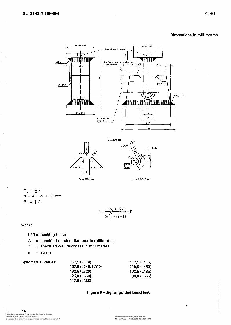
IS0 3183-1:1996(E) 0 IS0
Dimensions in millimetres
hardened I ‘oilers may be s”bstit”te
4 c ‘,’ ,. p* $’
46
‘i; \ ;I
B Adjustable type
Alternate Jigs
Wrap-around type
RA = $4
B = A + 2T + 3,2mm RB = +B
where
I,15 = peaking factor
D = specified outside diameter in millimetres T = specified wall thickness in millimetres
e = strain
Specified e values: 167,5 (L210) 112,5 (L415) 137,5 (L245, L290) 1 IO,0 (L450) 132,5 (L320) 102,5 (L485) 125,0 (L360) 90,o (L555) 117,5 (L385)
Figure 6 - Jig for guided bend test
54 Copyright International Organization for Standardization Provided by IHS under license with ISO Licensee=Aramco HQ/9980755100
Not for Resale, 04/12/2006 02:18:28 MDTNo reproduction or networking permitted without license from IHS
--``,,`,```````,`````,,,,,,`,`,-`-`,,`,,`,`,,`---
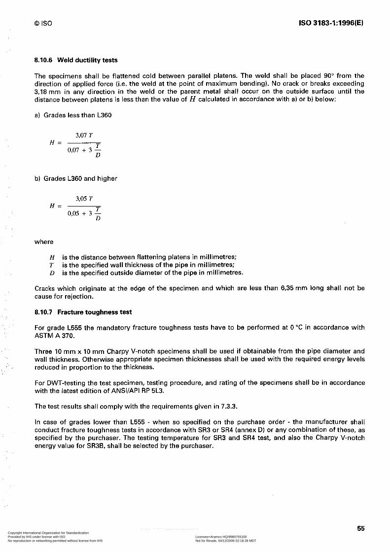
0 IS0 IS0 3183-1:1996(E)
8.10.6 Weld ductility tests
The specimens shall be flattened cold between parallel platens. The weld shall be placed 90” from the direction of applied force (i.e. the weld at the point of maximum bending). No crack or breaks exceeding 3,18 mm in any direction in the weld or the parent metal shall occur on the outside surface until the distance between platens is less than the value of H calculated in accordance with a) or b) below:
a) Grades less than L360
3,07 T H=
0,07 + 3 ;
b) Grades L360 and higher
3,05 T H=
0,05 + 3 ;
where
H is the distance between flattening platens in millimetres; T is the specified wall thickness of the pipe in millimetres; D is the specified outside diameter of the pipe in millimetres.
Cracks which originate at the edge of the specimen and which are less than 6,35 mm long shall not be cause for rejection.
8.10.7 Fracture toughness test
For grade L555 the mandatory fracture toughness tests have to be performed at 0 “C in accordance with ASTM A 370.
Three 10 mm x 10 mm Charpy V-notch specimens shall be used if obtainable from the pipe diameter and wall thickness. Otherwise appropriate specimen thicknesses shall be used with the required energy levels reduced in proportion to the thickness.
For DWT-testing the test specimen, testing procedure, and rating of the specimens shall be in accordance with the latest edition of ANSI/API RP 5L3.
The test results shall comply with the requirements given in 7.3.3.
In case of grades lower than L555 - when so specified on the purchase order - the manufacturer shall conduct fracture toughness tests in accordance with SR3 or SR4 (annex D) or any combination of these, as specified by the purchaser. The testing temperature for SR3 and SR4 test, and also the Charpy V-notch energy value for SR3B, shall be selected by the purchaser.
55 Copyright International Organization for Standardization Provided by IHS under license with ISO Licensee=Aramco HQ/9980755100
Not for Resale, 04/12/2006 02:18:28 MDTNo reproduction or networking permitted without license from IHS
--``,,`,```````,`````,,,,,,`,`,-`-`,,`,,`,`,,`---

IS0 3183-1:1996(E) 0 IS0
8.10.8 Defective mechanical test specimen
For any of the mechanical tests in 8.5, any test specimen that shows defective preparation or material imperfections unrelated to the intent of the particular mechanical test, whether observed before or after testing, may be discarded and be replaced by another specimen from the same length of pipe.
8.10.9 Hydrostatic test
8.10.9.1 Testing conditions
Test pressures for all sizes of seamless pipe and for welded pipe with outside diameters c 508,O mm, shall be held for not less than 5 s. Test pressures for welded pipe with outside diameters 2 508,O mm shall be held for not less than 10 s. For threaded-and-coupled pipe, the test shall be applied with the couplings made up power-tight if this is specified on the purchase order, except that pipe with outside diameters > 323,9 mm may be tested in the plain-end condition. For threaded pipe furnished with couplings made up handling-tight, the hydrostatic test shall be made on the pipe in the plain-end or threads-only condition or with coupling applied, unless otherwise agreed upon by the interested parties.
8.10.9.2 Verification of hydrostatic test
In order to ensure that every length of pipe is tested to the required test pressure, each tester, except those on which continuous welded pipe is tested, shall be equipped with a recording gauge that will record the test pressure and the durationfor each length of pipe, or be equipped with some positive and automatic or interlocking device to prevent pipe from being classified as tested until the test requirements (pressure and time) have been complied with. Such records or charts shall be available for examination at the manufacturer’s facility by the purchaser’s inspectors when the purchaser is so represented at the manufacturer’s facility. The test pressure measuring device shall be calibrated by means of a dead weight tester, or equivalent, within four months prior to each use. Calibration records retention shall be per 8.3.
8.10.9.3 Test pressures
The minimum test pressures shall be the standard test pressures listed in tables 6, 7, 8 and 9 (or an alternative test pressure - see footnote 4 in table 9) or an intermediate or higher pressure at the discretion of the manufacturer unless specifically limited by the purchaser, or a higher pressure as agreed upon between the interested parties. The minimum test pressure for grades, outside diameters, and wall thicknesses not listed shall be computed by the formula given below. Where the unlisted wall is intermediate to walls whose test pressure has been arbitrarily assigned, the test pressure for the intermediate wall shall be equal to the test pressure specified for the next heavier wall thickness. When computed pressures are not an exact multiple of 100 kPa, they shall be rounded to the nearest 100 kPa.
The test pressures shall be computed by the following formula and rounded to the nearest 100 kPa.
2 000 ST P= D
where
p is the hydrostatic test pressure, in kilopascals; S is the fiber stress in megapascals, equal to a percentage of the specified minimum yield strength
for the various sizes as shown in table 15; T is the specified wall thickness, in millimetres; D is the specified outside diameter, in millimetres.
56 Copyright International Organization for Standardization Provided by IHS under license with ISO Licensee=Aramco HQ/9980755100
Not for Resale, 04/12/2006 02:18:28 MDTNo reproduction or networking permitted without license from IHS
--``,,`,```````,`````,,,,,,`,`,-`-`,,`,,`,`,,`---

0 IS0 IS0 3183-1:1996(E)
Table 15 - Percentage of specified minimum yield strength (SMYS) for calculation of S
Grade Outside diameter mm
% of SMYS for calculation of S
Standard test pressure 1 Alternative test pressure
1) Test pressures established arbitrarily. 2) Test pressures were limited to 17 200 kPa for 5 88,9 mm outside diameter, and to 19 300 kPa for sizes
> 88,9 mm outside diameter. Test pressures for other sizes established arbitrarily. 3) Test pressures for grades L290 to L555 were limited to 20 700 kPa to accommodate hydrostatic tester
limitations.
When the purchase order specifies a hydrostatic test that will produce a hoop stress greater than 90 % of the specified minimum yield strength, and when SR5 (see annex D) is specified on the purchase order, the test pressure shall be determined in accordance with SR5.
NOTES
14 The hydrostatic test pressures given herein are inspection test pressures which are not intended as a basis for design, and do not necessarily have any direct relationship to working pressures.
15 When hydrostatic testing in excess of 90 % of specified minimum yield strength, using the formula in 8.10.9.3, the applied forces for end sealing produce a compressive longitudinal stress which should be considered.
8.10.9.4 Supplementary hydrostatic test
For grades L290 and higher, the manufacturer, by agreement between the interested parties, shall make additional internal pressure tests, which may involve one or more of the following methods. In all supplementary hydrostatic tests, the formula shown in 8.10.9.3 shall be used for stress calculations. The conditions of test shall be as agreed upon.
a) Hydrostatic destructive tests in which the minimum length of the specimen is ten times the outside diameter of the pipe, but should not exceed 12,2 m.
b) Full-length destructive tests made by the “hydrostatic pressure water column” method.
c) Hydrostatic transverse yield strength tests using accurate strain gauges.
NOTE 16 Acceptable gauges are the roller-chain ring-expansion gauge, the “SR-4” (trade name) strain gauge, or other suitable gauges of a similar accuracy.
8.10.10 Dimensions, mass and length
The accuracy of all measuring instruments except ring and plug thread gauges used for acceptance/rejection shall be verified at least once every operating turn. Accuracy verification of rules, length measuring tapes and other non-adjustable measuring devices shall be defined as a visual check of markings legibility and the general wear of fixed reference points. The verification procedure of these working gauges shall be documented. The adjustable and non-adjustable designation utilized by the manufacturer shall be documented.
57 Copyright International Organization for Standardization Provided by IHS under license with ISO Licensee=Aramco HQ/9980755100
Not for Resale, 04/12/2006 02:18:28 MDTNo reproduction or networking permitted without license from IHS
--``,,`,```````,`````,,,,,,`,`,-`-`,,`,,`,`,,`---

IS0 3183-1:1996(E) 0 IS0
If measuring equipment, whose calibration or verification is required under the provisions of this part of IS0 3183, is subjected to such unusual or severe conditions that its accuracy would become questionable, recalibration or a new verification shall be performed before further use of the equipment.
8.10.10.1 Outside diameter
For pipe with outside diameters 2 114,3 mm, the outside diameter measurements on the body of the pipe shall be made at the mill with a diameter tape.
Measuring methods for the pipe ends and the out-of-roundness are defined in connection with tolerances in 7.6.8.2 and 7.6.8.3.
8.10.10.2 Wall thickness
Wall thickness measurements shall be made with a mechanical caliper or with a properly calibrated non- destructive inspection device of appropriate accuracy. In case of dispute, the measurement determined by use of the mechanical caliper shall govern. The mechanical caliper shall be fitted with contact pins having circular cross sections of 6‘35 mm diameter. The end of the pin contacting the inside surface of the pipe shall be rounded to a maximum radius of 38,lO mm for pipe with outside diameters 2 168,3 mm, a maximum radius of d/4 for pipe with outside diameters < 168,3 mm, with a minimum radius of 3,2 mm. The end of the pin contacting the outside surface of the pipe shall be either flat or rounded to a radius of not less than 38,lO mm.
8.10.10.3 Mass
Each length of pipe with outside diameters 2 141,3 mm, shall be weighed separately, and the carload masses determined. Lengths of pipe with outside diameters 2 114,3 mm shall be weighed either individually or in convenient lots, at the option of the manufacturer, and the carload masses determined. A carload is considered to be a minimum of 18 144 kg. Threaded-and-coupled pipe shall be weighed with the couplings screwed on, but without thread protectors except for carload weighings, for which proper allowance shall be made for the mass of thread protectors. Threaded-and-coupled pipe may be weighed without the couplings screwed on providing proper allowance is made for mass of the couplings.
8.10.10.4 Length
When pipe is furnished with threads and couplings, the length shall be measured to the outer face of the coupling. The length of threaded-and-coupled pipe may be determined without the couplings screwed on providing proper allowance is made for the length of the couplings. The accuracy of length measuring devices for length of pipe less than 30 m shall be + 0,03 m.
8.10.10.5 Straightness
Measurements may be made using a taut string or wire from end to end along the side of the pipe measuring the greatest deviation.
8.10.11 Non-destructive testing
8.10.11.1 Methods of inspection
Submerged arc-welds shall be inspected by radiological methods in accordance with 8.10.11.2. Such inspection shall be full length, or for a minimum distance of 203 mm from each end if the balance of the weld length is inspected by ultrasonic methods in accordance with 8.10.11.3.1 to 8.10.11.3.4.
Electric-welds shall be inspected by ultrasonic or electromagnetic methods in accordance with 8.10.11.3.1 to 8.10.11.3.4. If necessary to meet the full length (100 %I inspection requirements of 8.9, pipe ends shall
58 Copyright International Organization for Standardization Provided by IHS under license with ISO Licensee=Aramco HQ/9980755100
Not for Resale, 04/12/2006 02:18:28 MDTNo reproduction or networking permitted without license from IHS
--``,,`,```````,`````,,,,,,`,`,-`-`,,`,,`,`,,`---

0 IS0 IS0 3183-1:1996(E)
be inspected by using hand-held ultrasonic shear wave equipment, or other NDT method agreed between the interested parties.
Gas metal arc-welds shall be inspected full length by ultrasonic methods in accordance with 8.10.11.3.1 to 8.10.11.3.4. In addition, the welds shall be inspected by radiological methods in accordance with 8.10.11.2 to 8.10.11.2.10 for a minimum distance of 203 mm from each end.
Strip end welds in finished helical seam pipe shall have been inspected in accordance with one or more of the methods specified above for the weld type. Radiological inspection shall include the junction of the strip end weld with the helical seam weld and, for cold expanded pipe, shall be performed after expansion.
8.10.11.2 Radiological inspection
8.10.11.2.1 Radiological inspection equipment
The homogeneity of weld seams examined by radiological methods shall be determined by means of X-rays directed through the weld material onto a suitable radiographic film or fluorescent screen, or a television screen provided adequate sensitivity can be obtained.
8.10.11.2.2 Fluoroscopic operator qualification
Operators of fluoroscopic equipment shall be trained, tested and certified by the pipe manufacturer.
Details of such training, testing and certification programmes shall be available to the purchaser. Included in these programmes shall be:
a) Classroom instructions in the fundamentals of radiological inspection techniques.
b) On the job training designed to familiarize the operator with specific installations including the appearance and interpretation of weld imperfections and defects. The length of time for such training shall be of sufficient duration to assure adequate assimilation of the knowledge required for conducting the inspection.
c) Knowledge of appropriate requirements of this specification.
d) A physical examination at least once per year to determine the operator’s optical capability to perform the required inspection.
e) Upon completion of a) and b) above, an examination shall be given by the manufacturer to determine if the operator is qualified to properly perform fluoroscopic examinations.
8.10.11.2.3 Operator certification
Certified operators whose work has not included fluoroscopic inspection for a period of one year or more shall be recertified by successfully completing the examination of e) above and also passing the physical examination of d) above. Substantial changes in procedure or equipment shall require recertification of the operators.
8.10.11.2.4 Radiological NDT reference standards
Unless otherwise specified, the reference standard shall be the API hole standard penetrameter described in a) below or, at the option of the manufacturer, the IS0 wire penetrameter (wire type image quality indicator in accordance with IS0 1027) described in b) below. By agreement between the interested parties, other standard penetrameters may be used.
a) API hole standard penetrameter: The API hole standard penetrameter shall be as shown in figure 7 and made of a material with the same radiological characteristics as the pipe. The thickness of the penetrameter shall be a maximum of 4 % of the nominal wall thickness. Either 2 % or 4 % penetrameters may be used, the sizes of which are shown in tables 16 and 17.
59 Copyright International Organization for Standardization Provided by IHS under license with ISO Licensee=Aramco HQ/9980755100
Not for Resale, 04/12/2006 02:18:28 MDTNo reproduction or networking permitted without license from IHS
--``,,`,```````,`````,,,,,,`,`,-`-`,,`,,`,`,,`---

IS0 3183-1:1996(E) 0 IS0
Dimensions in millimetres
T
I- 38
P k:-.
‘>.-.~.++ 1 v Identifying number
The diameter of each hole shall be I,6 mm. Holes shall be round and drilled perpendicular to the surface. Holes shall be free of burrs, but edges shall not be bevelled. Each penetrameter shall carry a lead identification number as given in tables 16 and 17.
Figure 7 - API standard penetrameter
Table 16 - API hole standard 4 % penetrameters
Identifying number Wall thickness Maximum penetrameter thickness
above I urlto I mm mm mm
10 4,8 I 64 0,25 12 6,4 73 0,32 15 73 93 0,38 17 93 II,1 0,45 20 II,1 12,7 0,51
I 25 I 12.7 I 15.9 I 0.64 I 30 15,9 19,l 0,76 40 19,l 25,4 I,02 50 25,4 31,8 I,27 60 31,8 38,l I,52
60 Copyright International Organization for Standardization Provided by IHS under license with ISO Licensee=Aramco HQ/9980755100
Not for Resale, 04/12/2006 02:18:28 MDTNo reproduction or networking permitted without license from IHS
--``,,`,```````,`````,,,,,,`,`,-`-`,,`,,`,`,,`---
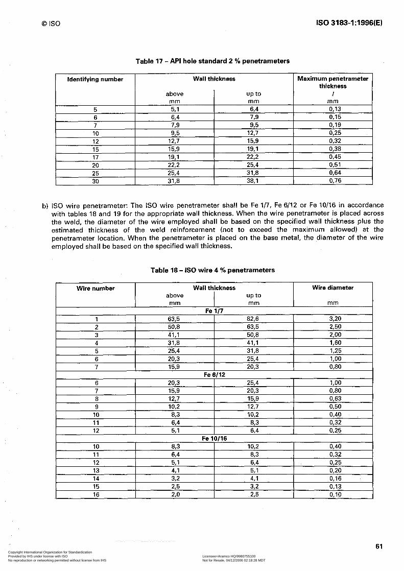
0 IS0 IS0 3183-1:1996(E)
Identifying number
Table 17 - API hole standard 2 % penetrameters
Wall thickness Maximum penetrameter thickness
above I
up to I mm mm mm 5.1 I 6.4 I 0.13 -,
7;i -I ~-
64 0,15 789 95 0,19 ne T ~~ 17~7 I 0~75 J,i) .-,. -,--
12,7 15,9 0,32 15,9 19,l 0,38 19.1 22.2 0.45 22.2 I 25.4 I 0.51 25.4 I 31.8 I 0.64
b) IS0 wire penetrameter: The IS0 wire penetrameter shall be Fe l/7, Fe 6/12 or Fe IO/16 in accordance with tables 18 and 19 for the appropriate wall thickness. When the wire penetrameter is placed across the weld, the diameter of the wire employed shall be based on the specified wall thickness plus the estimated thickness of the weld reinforcement (not to exceed the maximum allowed) at the penetrameter location. When the penetrameter is placed on the base metal, the diameter of the wire employed shall be based on the specified wall thickness.
Table 18 - IS0 wire 4 % penetrameters
Wall thickness
I
Wire diameter above I up to I
Wire number
I 6 I 20.3 I 25.4 I 1.00 I
I 11 I 6.4 I 8.3 I 0.32 I 12 5,l 64 0,25 13 4,l 5,l 0,20 14 32 4,l 0,16 15 23 32 0,13 16 2,o 23 0,lO
61 Copyright International Organization for Standardization Provided by IHS under license with ISO Licensee=Aramco HQ/9980755100
Not for Resale, 04/12/2006 02:18:28 MDTNo reproduction or networking permitted without license from IHS
--``,,`,```````,`````,,,,,,`,`,-`-`,,`,,`,`,,`---
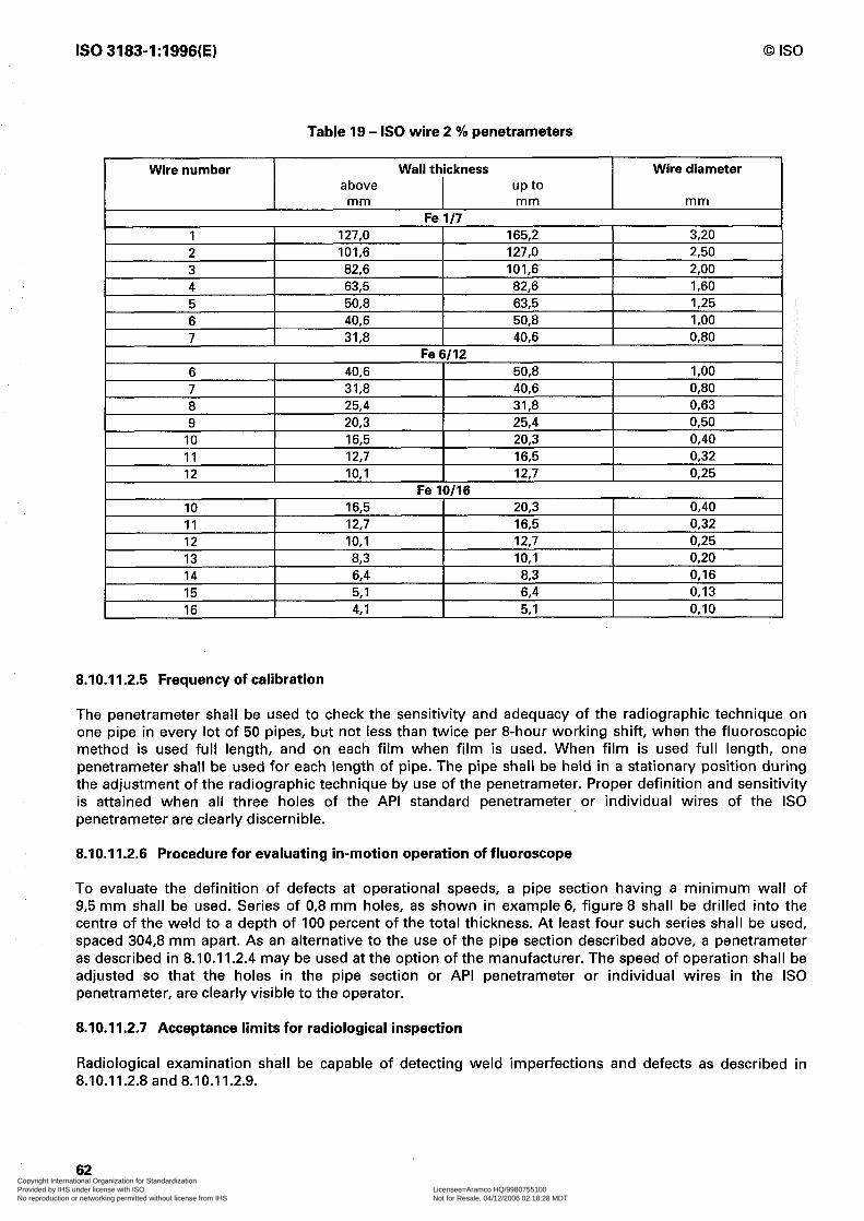
IS0 3183-1:1996(E) 0 IS0
Table 19 - IS0 wire 2 % penetrameters
Wire number Wire diameter
10 11 12
10 11 12 13 14 15
16,5 12,7 IO,1
16,5 12,7 IO,1 83 6,4 5,l
Fe IO/16
20,3 0,40 16,5 0,32 12,7 0,25
20,3 0,40 16,5 0,32 12,7 0,25 IO,1 0,20
83 0,16 6,4 0,13
8.10.11.2.5 Frequency of calibration
The penetrameter shall be used to check the sensitivity and adequacy of the radiographic technique on one pipe in every lot of 50 pipes, but not less than twice per 8-hour working shift, when the fluoroscopic method is used full length, and on each film when film is used. When film is used full length, one penetrameter shall be used for each length of pipe. The pipe shall be held in a stationary position during the adjustment of the radiographic technique by use of the penetrameter. Proper definition and sensitivity is attained when all three holes of the API standard penetrameter or individual wires of the IS0 penetrameter are clearly discernible.
8.10.11.2.6 Procedure for evaluating in-motion operation of fluoroscope
To evaluate the definition of defects at operational speeds, a pipe section having a minimum wall of 9,5 mm shall be used. Series of 0,8 mm holes, as shown in example 6, figure 8 shall be drilled into the centre of the weld to a depth of 100 percent of the total thickness. At least four such series shall be used, spaced 304,8 mm apart. As an alternative to the use of the pipe section described above, a penetrameter as described in 8.10.11.2.4 may be used at the option of the manufacturer. The speed of operation shall be adjusted so that the holes in the pipe section or API penetrameter or individual wires in the IS0 penetrameter, are clearly visible to the operator.
8.10.11.2.7 Acceptance limits for radiological inspection
Radiological examination shall be capable of detecting weld imperfections and defects as described in 8.10.11.2.8 and 8.10.11.2.9.
62 Copyright International Organization for Standardization Provided by IHS under license with ISO Licensee=Aramco HQ/9980755100
Not for Resale, 04/12/2006 02:18:28 MDTNo reproduction or networking permitted without license from IHS
--``,,`,```````,`````,,,,,,`,`,-`-`,,`,,`,`,,`---

0 IS0 IS0 3183-1:1996(E)
’
Example 1 : two 3,2 mm discontinuities
,
l l a 6
4
Example 2 : one 3.2 mm, one 1,6 mm, two 0.8 mm discontinuities
0 l . . . . . . + Example 3 : one 3.2 mm, one 0.8 mm, six 0.4 mm discontinuities
0 0 0 0
Example 4 : four 1.6 mm discontinuities
1
0 0 . l b .
Example 5 : two 1.6 mm, four 0.8 mm discontinuities
Example 6 : eight 0.8 mm discontinuities
. . . . . . . . . . . . . . . .
Example 7 : sixteen 0,4 mm discontinuities
. . . . . . . . . . . .
. .
Example 6 : scattered, three 0.8 mm, ten 0,4 mm discontinuities
Figure 8 - Examples of maximum distribution patterns of indicated circular slag-inclusion and gas-pocket-type discontinuities
63 Copyright International Organization for Standardization Provided by IHS under license with ISO Licensee=Aramco HQ/9980755100
Not for Resale, 04/12/2006 02:18:28 MDTNo reproduction or networking permitted without license from IHS
--``,,`,```````,`````,,,,,,`,`,-`-`,,`,,`,`,,`---
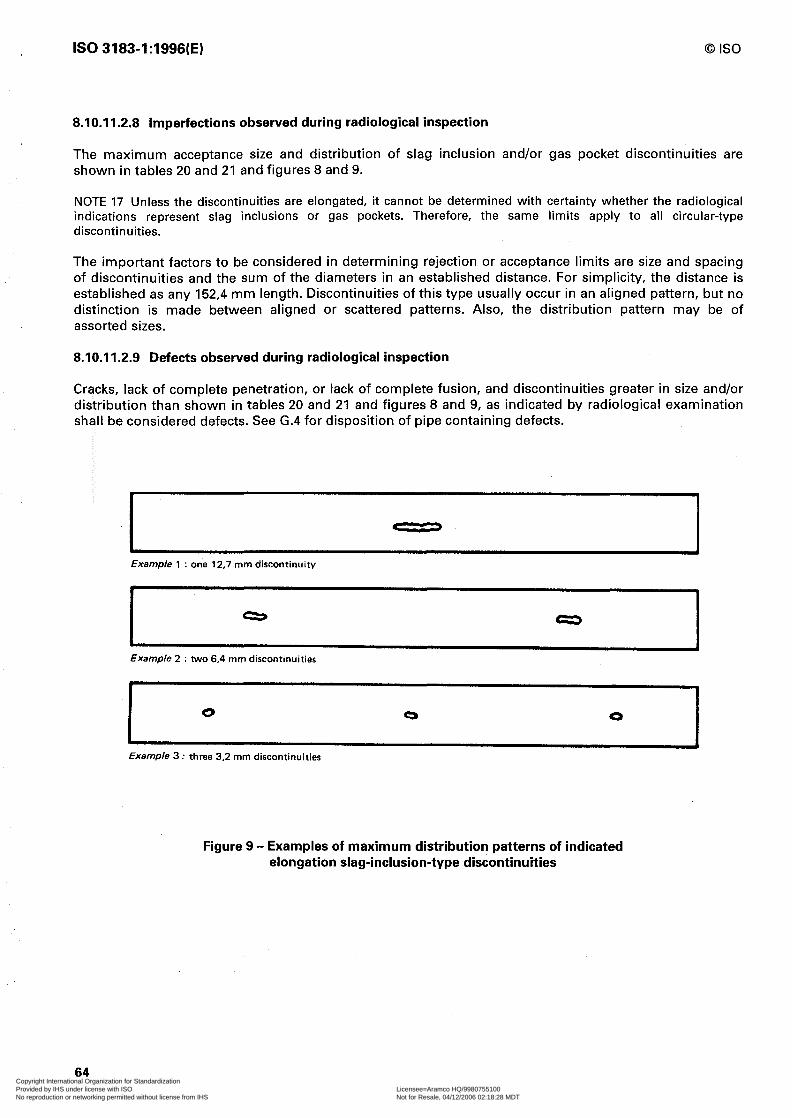
IS0 3183-1:1996(E) 0 IS0
8.10.11.2.8 imperfections observed during radiological inspection
The maximum acceptance size and distribution of slag inclusion and/or gas pocket discontinuities are shown in tables 20 and 21 and figures 8 and 9.
NOTE 17 Unless the discontinuities are elongated, it cannot be determined with certainty whether the radiological indications represent slag inclusions or gas pockets. Therefore, the same limits apply to all circular-type discontinuities.
The important factors to be considered in determining rejection or acceptance limits are size and spacing of discontinuities and the sum of the diameters in an established distance. For simplicity, the distance is established as any 152,4 mm length. Discontinuities of this type usually occur in an aligned pattern, but no distinction is made between aligned or scattered patterns. Also, the distribution pattern may be of assorted sizes.
8.10.11.2.9 Defects observed during radiological inspection
Cracks, lack of complete penetration, or lack of complete fusion, and discontinuities greater in size and/or distribution than shown in tables 20 and 21 and figures 8 and 9, as indicated by radiological examination shall be considered defects. See G.4 for disposition of pipe containing defects.
Example 1 : one 12,7 mm discontinuity
Example 2 : two 6.4 mm discontinuities
Example 3 : three 3.2 mm discontinuities
Figure 9 - Examples of maximum distribution patterns of indicated elongation slag-inclusion-type discontinuities
64 Copyright International Organization for Standardization Provided by IHS under license with ISO Licensee=Aramco HQ/9980755100
Not for Resale, 04/12/2006 02:18:28 MDTNo reproduction or networking permitted without license from IHS
--``,,`,```````,`````,,,,,,`,`,-`-`,,`,,`,`,,`---
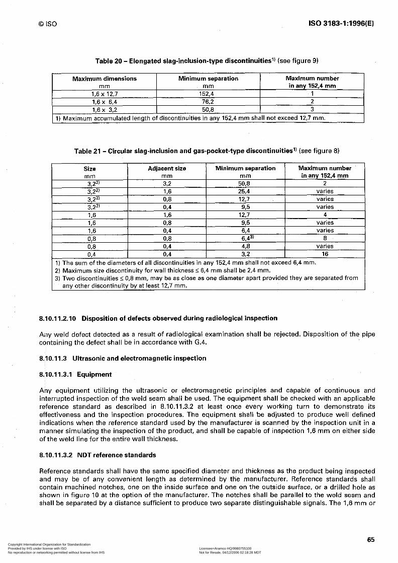
0 IS0 IS0 3183-1:1996(E)
Table 20 - Elongated slag-inclusion-type discontinuitiesl) (see figure 9)
Maximum dimensions Minimum separation Maximum number mm mm in any 152,4 mm
I,6 x 12,7 152,4 1 I,6 x 6,4 76,2 2 I,6 x 3,2 50,8 3
1) Maximum accumulated length of discontinuities in any 152,4 mm shall not exceed 12,7 mm.
Table 21 - Circular slag-inclusion and gas-pocket-type discontinuitiesl) (see figure 8)
Size I Adjacent size I Minimum separation 1 Maximum number I mm
3,22’ 3,2*’ 3,22r 3.22)
mm 3,2 I,6 0,8 0.4
mm in any 152.4 mm 50,8 2 25,4 varies 12,7 varies
9.5 varies I,6 I,6 I 12,7 4 I,6 0,8 I,6 0,4 083 088 03 0,4 OR4 0,4
93 varies 6,4 varies 6,43’ 8 4,8 varies 32 16
1) The sum of the diameters of all discontinuities in any 152,4 mm shall not exceed 6,4 mm. 2) Maximum size discontinuity for wall thickness 5 6,4 mm shall be 2,4 mm. 3) Two discontinuities I 0,8 mm, may be as close as one diameter apart provided they are separated from
any other discontinuity by at least 12,7 mm.
8.10.11.2.10 Disposition of defects observed during radiological inspection
Any weld defect detected as a result of radiological examination shall be rejected. Disposition of the pipe containing the defect shall be in accordance with G.4.
8.10.11.3 Ultrasonic and electromagnetic inspection
8.10.11.3.1 Equipment
Any equipment utilizing the ultrasonic or electromagnetic principles and capable of continuous and interrupted inspection of the weld seam shall be used. The equipment shall be checked with an applicable reference standard as described in 8.10.11.3.2 at least once every working turn to demonstrate its effectiveness and the inspection procedures. The equipment shall be adjusted to produce well defined indications when the reference standard used by the manufacturer is scanned by the inspection unit in a manner simulating the inspection of the product, and shall be capable of inspection I,6 mm on either side of the weld line for the entire wall thickness.
8.10.11.3.2 NDT reference standards
Reference standards shall have the same specified diameter and thickness as the product being inspected and may be of any convenient length as determined by the manufacturer. Reference standards shall contain machined notches, one on the inside surface and one on the outside surface, or a drilled hole as shown in figure 10 at the option of the manufacturer. The notches shall be parallel to the weld seam and shall be separated by a distance sufficient to produce two separate distinguishable signals. The I,6 mm or
65 Copyright International Organization for Standardization Provided by IHS under license with ISO Licensee=Aramco HQ/9980755100
Not for Resale, 04/12/2006 02:18:28 MDTNo reproduction or networking permitted without license from IHS
--``,,`,```````,`````,,,,,,`,`,-`-`,,`,,`,`,,`---

IS0 3183-1:1996(E) 0 IS0
3,2 mm hole shall be drilled through the wall and perpendicular to the surface of the reference standard as shown in figure IO.
NOTE 18 The reference standard defined above are convenient standards for calibration of non-destructive testing equipment. The dimensions of these standards should not be construed as the minimum size imperfection detectable by such equipment.
8.10.11.3.3 Acceptance limits
Table 22 gives the height of acceptance limit signals produced by reference standards. An imperfection that produces a signal greater than the acceptance limit signal given in table 22 shall be considered a defect unless it can be demonstrated by the manufacturer that the imperfection does not exceed the provisions of G-3. Alternatively, indicated imperfections in submerged-arc welds may be reinspected by film radiological methods using 2 % penetrameters, in accordance with 8.10.11.2.
Table 22 - Acceptance limits
Weld type
Submerged arc, gas metal arc and repair welds
Electric-weld
Notch type
N5
All other N 10, V IO
B, P
Size hole mm I,6
32 32
Acceptance limit signal %
100
33 l/3 100 80
In addition, for gas metal arc-welds, continuous flaw signals greater than 254 mm length, regardless of signal height, but greater than the background signal (noise) shall be reinspected by radiological methods in accordance with 8.10.11.2 (as modified above) or by other techniques as agreed upon between the interested parties.
8.10.11.3.4 Weld repair
Defects in the weld, found by ultrasonic or electromagnetic methods of inspection, may be repaired by welding and non-destructively reexamined in accordance with G.5.
8.10.11.3.5 Reinspection of pipe ends
For cold expanded welded pipe non-destructively inspected only prior to cold expansion, the weld at each end of each length shall be non-destructively reinspected subsequent to cold expansion for a distance of at least 152,4 mm by any of the methods specified in 8.10.11.1 or by the magnetic particle method in accordance with 8.10.11.4.
8.10.11.4 Magnetic particle inspection
(For pipe ends per 8.10.11.3.5 and for weld repairs to the pipe body.)
8.10.11.4.1 Equipment
The equipment used for magnetic particle inspection shall produce a magnetic field, transverse to the weld and of sufficient intensity to indicate weld area defects in the external surface of the pipe of the following character: open welds, partial or incomplete welds, intermittent welds, cracks, seams and slivers.
66 Copyright International Organization for Standardization Provided by IHS under license with ISO Licensee=Aramco HQ/9980755100
Not for Resale, 04/12/2006 02:18:28 MDTNo reproduction or networking permitted without license from IHS
--``,,`,```````,`````,,,,,,`,`,-`-`,,`,,`,`,,`---

0 IS0 IS0 3183-1:1996(E)
Dimensions in millimetres
B (buttress) notch
60” max.
+Fy
I VI0 notch
Area of each side, 3.N mm* max.
P (parallel slded) notch
1 max. t-r--i
Length For eddy current: 38 mm max. total length For diverted flux and ultrasonic: 50 mm min. at full depth
N5andNlOnotches
\ \ I I
Orllled hole
Figure 10 - Reference standards (see 8.10.11.3.2)
67 Copyright International Organization for Standardization Provided by IHS under license with ISO Licensee=Aramco HQ/9980755100
Not for Resale, 04/12/2006 02:18:28 MDTNo reproduction or networking permitted without license from IHS
--``,,`,```````,`````,,,,,,`,`,-`-`,,`,,`,`,,`---

IS0 3183-1:1996(E) 0 IS0
8.10.11.4.2 Reference standard
If requested by the purchaser, arrangements shall be made by the manufacturer to perform a demonstration for the purchaser or his representative during production of his order. Such demonstration shall be on basis of pipe in process or sample lengths of similar pipe retained by the manufacturer for that purpose and which exhibit natural or artificially produced defects of the character stated in 8.10.11.4.1.
8.10.11.4.3 Acceptance limits
The manufacturer shall mark each magnetic particle indication and subsequently explore each indication with respect to depth of the imperfection. Imperfections which require grinding or chipping to determine their depth shall be completely removed by grinding, or by cutting off, or may be repaired by welding in accordance with G.5 and reexamined non-destructively.
8.11 Invalidation of chemical, mechanical and technological tests
A test will be invalid (see also IS0 404, 8.4) if the results are unsatisfactory due to:
a) faulty production of the test piece not attributable to defects in the steel itself;
b) faulty mounting of the test piece;
c) faulty working of the test machine.
In each of these cases, the test shall be repeated.
8.12 Re-tests
8.12.1 Analyses
If the product analyses of both samples representing the cast fail to conform to the specified requirements, at the manufacturer’s option either the cast shall be rejected or the remainder of the cast shall be tested individually for conformity to the specified requirements. If the product analysis of only one of the samples representing the cast fails to conform to the specified requirements, at the manufacturer’s option either the cast shall be rejected or two recheck analyses shall be made using two additional samples from the cast. If both recheck analyses conform to the specified requirements, the cast shall be accepted, except for the pipe, plate or skelp, from which the initial sample that failed was taken. If one or both recheck analyses fail to conform to the specified requirements, at the manufacturer’s option either the cast shall be rejected or the remainder of the cast shall be tested individually for conformance to the specified requirements.
For such individual testing, analyses for only the rejecting element or elements need to be determined.
Samples for recheck analyses shall be taken in the same location as specified for product analysis samples.
8.12.2 Tensile test
If the tensile test specimen representing a lot of pipe fails to conform to the specified requirements, the manufacturer may elect to make retests on two additional lengths from the same lot. If both retest specimens conform to the requirements, all the lengths in a lot shall be accepted, except the length from which the initial specimen was taken. If one or both of the retest specimens fail to conform to the specified requirements, the manufacturer may elect to test individually the remaining lengths in the lot, in which case determinations are required only for particular requirements with which the specimens failed to comply in the preceding tests. Specimen for retest shall be taken in the same manner as the specimen which failed to meet the minimum requirements.
68 Copyright International Organization for Standardization Provided by IHS under license with ISO Licensee=Aramco HQ/9980755100
Not for Resale, 04/12/2006 02:18:28 MDTNo reproduction or networking permitted without license from IHS
--``,,`,```````,`````,,,,,,`,`,-`-`,,`,,`,`,,`---
0 IS0 IS0 3183-1:1996(E)
8.12.2.1 Defective tensile test specimen
When the elongation of any tensile test specimen is less than that specified and if any part of the fracture is outside the middle third of the gauge length, as indicated by scribe scratches marked on the specimen before testing, a retest shall be allowed.
8.12.3 Flattening test
Flattening retest provisions are as follows.
Non-expanded electric-welded pipe produced in single length, higher than grade L 175.
Manufacturer may elect to retest any failed end until the requirements are met providing the finished pipe is not less than 80 % of its length after initial cropping.
Non-expanded electric-welded pipe produced in multiple lengths, higher than grade L 775.
Manufacturer may elect to retest each end of each individual length if any test fails. The retests for each end of each individual length shall be made with the weld alternately at 0” and 90”.
Cold-expanded electric-welded pipe higher than grade Ll75 and all welded L175 pipe with outside diameters _< 73,0 mm.
Manufacturer may elect to retest one end from each of two additional lengths of the same lot. If both retests are acceptable, all lengths in the lot shall be accepted, except the original failed length. If one or both retests fail, the manufacturer may elect to repeat the test on specimens cut from one end of each of the remaining individual lengths in the lot.
8.12.4 Bend test
If the specimen fails to conform to the specified requirements, the manufacturer may elect to make retests on specimens cut from two additional lengths from the same lot. If all retest specimens conform to the specified requirements, all lengths in the lot shall be accepted, except the length from which the initial specimen was taken. If one or more of the retest specimens fail to conform to the specified requirements, the manufacturer may elect to repeat the test on specimens cut from the individual lengths remaining in the lot.
8.12.5 Guided-bend test
If one or both of the guided-bend specimens fail to conform to the specified requirements, the manufacturer may elect to repeat the tests on specimens cut from two additional lengths of pipe from the same lot. If such specimens conform to the specified requirements, all lengths in the lot shall be accepted, except the length initially selected for test. If any of the retest specimens fail to pass the specified requirements, the manufacturer may elect to test specimens cut from the individual lengths remaining in the lot. The manufacturer may also elect to retest any length which has failed to pass the test by cropping back and cutting two additional specimens from the same end. If the requirements of the original test are met by both of these additional tests, that length shall be acceptable. No further cropping and retesting is permitted. Specimens for retests shall be taken in the same manner as specified in 8.5.2.4.
8.12.6 Weld ductility test
If the weld ductility test specimen representing a lot of pipe fails to conform to the specified requirements of 8.5.2.5, the manufacturer may elect to make retests on two additional lengths from the same lot. If both retest specimens conform to the requirements, all the lengths in the lot shall be accepted, except the length from which the initial specimen was taken. If one or both of the retest specimens fail to conform to the specified requirements, the manufacturer may elect to test specimens cut from one end of the
69 Copyright International Organization for Standardization Provided by IHS under license with ISO Licensee=Aramco HQ/9980755100
Not for Resale, 04/12/2006 02:18:28 MDTNo reproduction or networking permitted without license from IHS
--``,,`,```````,`````,,,,,,`,`,-`-`,,`,,`,`,,`---

IS0 3183-1:1996(E) 0 IS0
individual lengths remaining in the lot. Precaution shall be taken so that the specimens can be identified with respect to the length of pipe from which they were cut. The manufacturer may also elect to retest any length which has failed to pass the above test procedure by cropping back and cutting two additional specimens from the same end. If the weld ductility test requirements are met by both of these additional tests, that length shall be acceptable. No further cropping and retesting is permitted.
8.12.7 Fracture toughness test
For grade L555 retests shall not be made.
If the all-cast average of the order does not meet 68 J, the manufacturer shall be responsible for the replacement of casts as may be necessary to bring the average up to 68 J.
If the all-cast average of the order does not meet the required percent shear area, the manufacturer shall be responsible for replacement of such casts as may be necessary to bring the average to the required value.
For grades lower than L555 retests may be made in accordance with SR3 and SR4 (annex D).
9 Marking of pipes and pipe couplings
9.1 General
Pipes and pipe couplings manufactured in conformity with this part of IS0 3183 shall be marked by the manufacturer as specified hereinafter.
a) The required marking on pipe shall be paint stencilled as stipulated in 9.2.
b) The required marking on couplings shall be die stamped unless otherwise agreed between the interested parties, in which case they shall be paint stenciled.
c) Length and hydrostatic test pressure markings shall be in metric units.
9.2 Location of marking
The location of identification markings, shall be as follows:
Outside diameters < 48,3 mm - The marking requirements of 9.2 shall be die stamped on a metal tag fixed to the bundle, or may be printed on the straps or banding clips used to tie the bundle.
Seamless pipe in all other sizes and welded pipe outside diameters up to 406,4 mm - Paint stencil on the outside surface starting at a point between 457,0 mm and 762 mm from the end of the pipe, and in the sequence shown below, except when agreed between the interested parties some or all of the markings may be placed on the inside surface in a sequence convenient to the manufacturer.
Welded pipe outside diameters 2 406,4 mm - Paint stencil on the inside surface starting at a point no less than 152,4 mm from the end of the pipe in a sequence convenient to the manufacturer, unless otherwise specified by the purchaser.
70 Copyright International Organization for Standardization Provided by IHS under license with ISO Licensee=Aramco HQ/9980755100
Not for Resale, 04/12/2006 02:18:28 MDTNo reproduction or networking permitted without license from IHS
--``,,`,```````,`````,,,,,,`,`,-`-`,,`,,`,`,,`---

0 IS0 IS0 3183-1:1996(E)
8.12.2.1 Defective tensile test specimen
When the elongation of any tensile test specimen is less than that specified and if any part of the fracture is outside the middle third of the gauge length, as indicated by scribe scratches marked on the specimen before testing, a retest shall be allowed.
8.12.3 Flattening test
Flattening retest provisions are as follows.
Non-expanded electric-welded pipe produced in single length, higher than grade L 175.
Manufacturer may elect to retest any failed end until the requirements are met providing the finished pipe is not less than 80 % of its length after initial cropping.
Non-expanded electric-welded pipe produced in multiple lengths, higher than grade L 175.
Manufacturer may elect to retest each end of each individual length if any test fails. The retests for each end of each individual length shall be made with the weld alternately at 0” and 90”.
Cold-expanded electric-welded pipe higher than grade L175 and all welded L175 pipe with outside diameters _< 73,0 mm.
Manufacturer may elect to retest one end from each of two additional lengths of the same lot. If both retests are acceptable, all lengths in the lot shall be accepted, except the original failed length. If one or both retests fail, the manufacturer may elect to repeat the test on specimens cut from one end of each of the remaining individual lengths in the lot.
8.12.4 Bend test
If the specimen fails to conform to the specified requirements, the manufacturer may elect to make retests on specimens cut from two additional lengths from the same lot. If all retest specimens conform to the specified requirements, all lengths in the lot shall be accepted, except the length from which the initial specimen was taken. If one or more of the retest specimens fail to conform to the specified requirements, the manufacturer may elect to repeat the test on specimens cut from the individual lengths remaining in the lot.
8.12.5 Guided-bend test
If one or both of the guided-bend specimens fail to conform to the specified requirements, the manufacturer may elect to repeat the tests on specimens cut from two additional lengths of pipe from the same lot. If such specimens conform to the specified requirements, all lengths in the lot shall be accepted, except the length initially selected for test. If any of the retest specimens fail to pass the specified requirements, the manufacturer may elect to test specimens cut from the individual lengths remaining in the lot. The manufacturer may also elect to retest any length which has failed to pass the test by cropping back and cutting two additional specimens from the same end. If the requirements of the original test are met by both of these additional tests, that length shall be acceptable. No further cropping and retesting is permitted. Specimens for retests shall be taken in the same manner as specified in 8.5.2.4.
8.12.6 Weld ductility test
If the weld ductility test specimen representing a lot of pipe fails to conform to the specified requirements of 8.5.2.5, the manufacturer may elect to make retests on two additional lengths from the same lot. If both retest specimens conform to the requirements, all the lengths in the lot shall be accepted, except the length from which the initial specimen was taken. If one or both of the retest specimens fail to conform to the specified requirements, the manufacturer may elect to test specimens cut from one end of the
69 Copyright International Organization for Standardization Provided by IHS under license with ISO Licensee=Aramco HQ/9980755100
Not for Resale, 04/12/2006 02:18:28 MDTNo reproduction or networking permitted without license from IHS
--``,,`,```````,`````,,,,,,`,`,-`-`,,`,,`,`,,`---

IS0 3183-1:1996(E) 0 IS0
individual lengths remaining in the lot. Precaution shall be taken so that the specimens can be identified with respect to the length of pipe from which they were cut. The manufacturer may also elect to retest any length which has failed to pass the above test procedure by cropping back and cutting two additional specimens from the same end. If the weld ductility test requirements are met by both of these additional tests, that length shall be acceptable. No further cropping and retesting is permitted.
8.12.7 Fracture toughness test
For grade L555 retests shall not be made.
If the all-cast average of the order does not meet 68 J, the manufacturer shall be responsible for the replacement of casts as may be necessary to bring the average up to 68 J.
If the all-cast average of the order does not meet the required percent shear area, the manufacturer shall be responsible for replacement of such casts as may be necessary to bring the average to the required value.
For grades lower than L555 retests may be made in accordance with SR3 and SR4 (annex D).
9 Marking of pipes and pipe couplings
9.1 General
Pipes and pipe couplings manufactured in conformity with this part of IS0 3183 shall be marked by the manufacturer as specified hereinafter.
a) The required marking on pipe shall be paint stencilled as stipulated in 9.2.
b) The required marking on couplings shall be die stamped unless otherwise agreed between the interested parties, in which case they shall be paint stenciled.
c) Length and hydrostatic test pressure markings shall be in metric units.
9.2 Location of marking
The location of identification markings, shall be as follows:
Outside diameters I 48,3 mm - The marking requirements of 9.2 shall be die stamped on a metal tag fixed to the bundle, or may be printed on the straps or banding clips used to tie the bundle.
Seamless pipe in all other sizes and welded pipe outside diameters up to 406,4 mm - Paint stencil on the outside surface starting at a point between 457,0 mm and 762 mm from the end of the pipe, and in the sequence shown below, except when agreed between the interested parties some or all of the markings may be placed on the inside surface in a sequence convenient to the manufacturer.
Welded pipe outside diameters 2 406,4 mm - Paint stencil on the inside surface starting at a point no less than 152,4 mm from the end of the pipe in a sequence convenient to the manufacturer, unless otherwise specified by the purchaser.
70 Copyright International Organization for Standardization Provided by IHS under license with ISO Licensee=Aramco HQ/9980755100
Not for Resale, 04/12/2006 02:18:28 MDTNo reproduction or networking permitted without license from IHS
--``,,`,```````,`````,,,,,,`,`,-`-`,,`,,`,`,,`---

0 IS0 IS0 3183-1:1996(E)
9.3 Sequence of markings
The sequence of identification markings shall be as follows:
a) Manufacturer’s name or mark (XI
b) Designation of this part of IS0 3183 shall be marked when the product is in complete compliance with this International Standard.
c) Compatible standards. Products in compliance with multiple compatible standards may be marked with the name of each standard.
d) Designations. The size and mass designations are dimensionless quantities based on diameter and mass per metre. The size designation (see column 1, tables 6 to 9) shall be marked. For outside diameters 2 114,3 mm, the nominal mass for threaded-and-coupled pipe (see column 2, tables 6 and 7) and the tabulated mass for plain-end pipe (see M in column 1, tables 8 and 9) shall be marked.
e) Grade and class
The symbols to be used are as follows:
Grade L175 class I Grade Ll75 class II Grade L210 Grade L245 Grade L290 Grade L320 Grade L360 Grade L390 Grade L415 Grade L450 Grade L485 Grade L555
L175 L175 R L210 L245 L290 L320 L360 L390 L415 L450 L485 L555
For grades intermediate to L290 and L390, the symbol shall be “L” followed by the first three digits of the specified minimum yield strength.
For all grades L320 and higher, including intermediate grades, containing niobium, vanadium and/or titanium, the grade symbol shall be followed by the letter(s) C, V, T or combination thereof.
By agreement between the interested parties and when so specified on the purchase order, the grade shall be identified by colour in accordance with SR3 (annex D).
NOTE 19 See 7.1 for limitations on downgrading.
f) Process of manufacture
The symbols to be used are as follows:
Seamless pipe ............................................................................................................................................. S Welded pipe, except continuous welded ................................................................................................. W Continuous welded pipe ............................................................................................................................ F
71 Copyright International Organization for Standardization Provided by IHS under license with ISO Licensee=Aramco HQ/9980755100
Not for Resale, 04/12/2006 02:18:28 MDTNo reproduction or networking permitted without license from IHS
--``,,`,```````,`````,,,,,,`,`,-`-`,,`,,`,`,,`---
IS0 3183-1:1996(E) 0 IS0
g) Heat treatment
The symbols to be used are as follows:
Normalized or normalized and tempered . . . . . . . . . . . . . . . . . . . . . . . . . . . . . . . . . . . . . . . . . . . . . . . . . . . . . . . . . . . . . . . . . . . . . . . . . . . . . . . . . . . . . . . . . . . . . . . N Subcritical stress relieved . . . . . . . . . . . . . . . . . . . . . . . . . . . . . . . . . . . . . . . ..~............................................................................... HS Subcritical age hardened . . . . . . . . . . . . . . . . . . . . . . . . . . . . . . . . . . . . . . . . . . . . . . . . . . . . . . . . . . . . . . . . . . . . . . . . . . . . . . . . . . . . . . . . . . . . . . . . . . . . . . . . . . . . . . . . . . . . . . . . . . HA Quenched and tempered . . . . . . . . . . . . . . . . . . . . . . . . . . . . . . . . . . . . . . . . ..~.................. . . . . . . . . . . . . . . . . . . . . . . . . . . . . . . . . . . . . . . . . . . . . . . . . . . . . . . . . . . . . . Q
h) Test pressure
When the specified hydrostatic test pressure is higher than the tabulated pressure (see tables 6 to 9) the test pressure in kPa preceded by the word TESTED, shall be paint stencilled.
i) Supplementary requirements
See annex D.
EXAMPLES:
1. Size 14, mass 54,57, grade L245 seamless, regular-mass, plain-end pipe should be paint stencilled as follows:
X3183-1, 14 54,57 L245 S
2. Size 6 5/8, mass 18,97, grade L245, electric-welded, regular mass, plain-end pipe should be paint stencilled as follows:
X 3183-1, 6 518 18,97 L245 W
3. Nominal size 4, grade L175, continuous welded, class 1, standard-mass, threaded line pipe should be paint stencilled as follows:
X3183-1, 4 II,00 L175 F
4. Size 14, mass 54,57, grade L290, seamless, steel pipe should be paint stencilled as follows:
X 3183-1, 14 54,57 L290 S
5. Size 12 3/4,‘mass 43,77, grade L290, seamless plain-end pipe should be paint stencilled as follows:
X3183-1, 12 314 43,77 L290 S
6. Size 6 5/8, mass 14,97, grade L290, electric-welded plain-end pipe should be paint stencilled as follows:
X3183-1, 6 518 14,97 L290 W
7. Size 12 3/4, mass 43,77, grade L290, helical seam submerged arc-welded plain-end pipe should be paint stencilled as follows:
X3183-1, 12 314 43,77 L290 W
9.4 Bundle identification
For pipe with outside diameter I48,3 mm, the identification markings specified in 9.2 shall be placed on the tag, strap, or clip used to tie the bundle.
72 Copyright International Organization for Standardization Provided by IHS under license with ISO Licensee=Aramco HQ/9980755100
Not for Resale, 04/12/2006 02:18:28 MDTNo reproduction or networking permitted without license from IHS
--``,,`,```````,`````,,,,,,`,`,-`-`,,`,,`,`,,`---
0 IS0 IS0 3183-1:1996(E)
9.5 Length
In addition to the identification markings stipulated in 9.1, 9.2 and 9.3 the length shall be marked as follows:
a) For pipe with outside diameter > 48,3 mm, the length in metres and hundredths of metre, unless otherwise specified on the purchase order, as measured on the finished pipe shall be paint stencilled on the outside surface at a place convenient to the manufacturer, except by agreement between the interested parties the length marking may be placed inside the pipe at convenient location.
b) For pipe with outside diameter I48,3 mm, the total length of pipe in the bundle in metres and hundredths of metre unless otherwise specified on the purchase order, shall be marked on the tag, band or clip.
9.6 Couplings
All couplings in nominal size 2 and larger shall be identified with the manufacturer’s name or mark and “3183-1”.
9.7 Die stamping
Cold die-stamping of grades higher than L175 plate or pipe not subsequently heat treated, and all pipe with wall thickness 5 4,0 mm is prohibited, except that by agreement between the interested parties and when so specified on the purchase order, pipe or plate may be cold die stamped. The manufacturer, at his option, may hot die stamp (93 “C or higher) plate or pipe, cold die stamp plate or pipe if it is subsequently heat treated and cold die stamp couplings. Cold die-stamping shall be done with rounded or blunt dies. All die-stamping shall be at least 25,4 mm from the weld for all grades except grade L175.
9.8 Thread identification
At the manufacturer’s option, any pipe threads which conform to the threading and gauging stipulation given in the latest edition of IS0 10422 may be identified by stamping or stencilling the product adjacent to such thread, with the manufacturer’s name or mark, the size and the letters LP to indicate the type of thread.
For example, nominal size 6 IS0 line pipe threads may be marked:
X 104226LP
If the product is clearly marked elsewhere with the manufacturer’s identification, his name or mark may be omitted.
9.9 Thread certification
The use of the letters as provided in 9.7 shall constitute a certification by the manufacturer that the threads so marked comply with the requirements stipulated in the latest edition of IS0 10422, but should not be construed by the purchaser as a representation that the product so marked is, in its entirety, in accordance with any IS0 Standard.
73 Copyright International Organization for Standardization Provided by IHS under license with ISO Licensee=Aramco HQ/9980755100
Not for Resale, 04/12/2006 02:18:28 MDTNo reproduction or networking permitted without license from IHS
--``,,`,```````,`````,,,,,,`,`,-`-`,,`,,`,`,,`---

IS0 3183-1:1996(E) 0 IS0
9.10 Pipe processor markings
Pipe heat treated by a processor other than the original pipe manufacturer shall be marked as stipulated in 9.1 to 9.7. The processor shall remove any identity which is not indicative of the new condition of the product as a result of heat treating (i.e. prior grade identity, original pipe manufacturer’s name or logo).
10 Protective coatings
Unless otherwise ordered, pipe shall be given an external coating to protect it from rusting in transit. An attempt should be made to make these coatings smooth, hard to the touch, and with minimum sags.
NOTE 20 If bare pipe or specially coated pipe is desired, the purchase order should so state. For special coatings, the purchase order should state further whether the coating is to be applied to the full length or whether a certain specified distance from the end is to be left uncoated. Unless otherwise specified, such bare ends are commonly given a coating with oil for protection in transit.
74 Copyright International Organization for Standardization Provided by IHS under license with ISO Licensee=Aramco HQ/9980755100
Not for Resale, 04/12/2006 02:18:28 MDTNo reproduction or networking permitted without license from IHS
--``,,`,```````,`````,,,,,,`,`,-`-`,,`,,`,`,,`---
0 IS0 IS0 3183-1:1996(E)
Annex A (normative)
Specification for welded jointers
A.1 Method
Welding of any type that uses deposited filler metal and is generally recognized as sound practice shall be permitted unless the purchaser specifies a particular method. Welding procedures, and welders and welding machine operators (hereafter operators) shall be qualified in accordance with API Standard 1104. Copies of the welding procedure specification and procedure qualification record shall be provided to the purchaser upon request.
A.2 Workmanship
The ends of the pipe to be welded together shall be prepared in accordance with the requirements of the procedure used. Pipe weld seams (straight, helical or strip) shall be staggered between 51 mm and 203 mm unless specified otherwise by the purchaser. The completed jointers shall be straight within the limits specified in 7.6.6. Each weld shall have a substantially uniform cross section around the entire circumference of the pipe. At no point shall its crowned surface be below the outside surface of the parent metal nor shall it rise above the latter by more than 3,18 mm if submerged arc-welded, or by more than I,59 mm if welded by another process.
A.3 Marking
Each jointer shall be marked to identify the welder or operator, using paint stencil.
A.4 Non-destructive testing
The girth welds of jointers shall be 100 % radiographed in accordance with the procedures and standards of acceptability in API Standard 1104. Jointer welds failing to pass this radiographic examination may be repaired and re-radiographed in accordance with the procedures and acceptance criteria of API Standard 1104.
NOTE 21 See also 7.6.7 for length requirements on jointers.
75 Copyright International Organization for Standardization Provided by IHS under license with ISO Licensee=Aramco HQ/9980755100
Not for Resale, 04/12/2006 02:18:28 MDTNo reproduction or networking permitted without license from IHS
--``,,`,```````,`````,,,,,,`,`,-`-`,,`,,`,`,,`---

IS0 3183-1:1996(E) 0 IS0
Annex B (normative)
Repair welding procedure
B. 1 General
All repair welds shall be made in the flat position according to a qualified procedure and by a welding machine operator (hereafter operator) or repair welder qualified in a flat position, as specified in B.2. Repair welds may be made by one of the following methods:
- automatic submerged arc; - automatic or semi-automatic gas metal arc; - manual shielded metal arc using low hydrogen electrodes.
All welding materials shall be properly handled and stored in accordance with the manufacturer’s recommendations so as to preclude moisture or other contamination. Test welds may be made on either plate stock or pipe stock at the option of the manufacturer.
The manufacturer shall maintain a record of the welding procedure and procedure qualification test results; copies of the welding procedure specification and procedure qualification record shall be provided to the purchaser upon request.
B.2 Repair welding procedure qualification
Welding procedures shall be qualified by preparing and testing welds in accordance with this annex B. At the option of the manufacturer, the tests specified in the latest issue of the ASME Boiler and Pressure Vessel Code, Section IX may be substituted herein. For the purpose of this annex, the term automatic welding includes both machine welding and automatic welding as defined in the ASME Boiler and Pressure Vessel Code, Section IX.
B.2.1 Essential variables
An existing procedure shall not be applicable and new procedure shall be qualified when any of the following essential variables is changed beyond the stated limits.
B.2.1.1 Welding process
a) A change in the welding procedure (i.e. submerged arc to gas metal arc).
b) A change in the method (i.e. manual to semi-automatic).
B.2.1.2 Pipe material
a) A change in grade category. When different alloying systems are used within one grade category, each alloying composition shall be separately qualified. Grade categories are as follows:
- SMYS I290 N/mm2; - SMYS > 290 N/mm*, but < 450 N/mm*; - each grade with SMYS 2 450 N/mm*.
b) Within each grade category, a thicker material than the material qualified.
76 Copyright International Organization for Standardization Provided by IHS under license with ISO Licensee=Aramco HQ/9980755100
Not for Resale, 04/12/2006 02:18:28 MDTNo reproduction or networking permitted without license from IHS
--``,,`,```````,`````,,,,,,`,`,-`-`,,`,,`,`,,`---
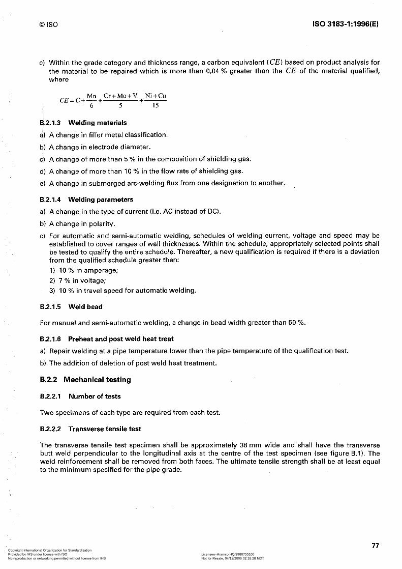
0 IS0 IS0 3183-1:1996(E)
c) Within the grade category and thickness range, a carbon equivalent (CE) based on product analysis for the material to be repaired which is more than 0,04 % greater than the CE of the material qualified, where
Mn Cr+Mo+V + Ni+Cu cE=c+6+ 5 15
B.2.1.3 Welding materials
a) A change in filler metal classification.
b) A change in electrode diameter.
c) A change of more than 5 % in the composition of shielding gas.
d) A change of more than 10 % in the flow rate of shielding gas.
e) A change in submerged arc-welding flux from one designation to another.
B.2.1.4 Welding parameters
a) A change in the type of current (i.e. AC instead of DC).
b) A change in polarity.
c) For automatic and semi-automatic welding, schedules of welding current, voltage and speed may be established to cover ranges of wall thicknesses. Within the schedule, appropriately selected points shall be tested to qualify the entire schedule. Thereafter, a new qualification is required if there is a deviation from the qualified schedule greater than: 1) 10 % in amperage; 2) 7 % in voltage; 3) 10 % in travel speed for automatic welding.
B.2.1.5 Weld bead
For manual and semi-automatic welding, a change in bead width greater than 50 %.
B.2.1.6 Preheat and post weld heat treat
a) Repair welding at a pipe temperature lower than the pipe temperature of the qualification test.
b) The addition of deletion of post weld heat treatment.
B.2.2 Mechanical testing
B.2.2.1 Number of tests
Two specimens of each type are required from each test.
B.2.2.2 Transverse tensile test
The transverse tensile test specimen shall be approximately 38 mm wide and shall have the transverse butt weld perpendicular to the longitudinal axis at the centre of the test specimen (see figure B.1). The weld reinforcement shall be removed from both faces. The ultimate tensile strength shall be at least equal to the minimum specified for the pipe grade.
77 Copyright International Organization for Standardization Provided by IHS under license with ISO Licensee=Aramco HQ/9980755100
Not for Resale, 04/12/2006 02:18:28 MDTNo reproduction or networking permitted without license from IHS
--``,,`,```````,`````,,,,,,`,`,-`-`,,`,,`,`,,`---
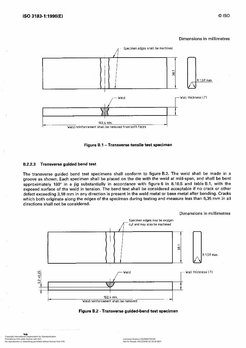
IS0 3183-1:1996(E) 0 IS0
Dimensions in millimetres
A- Specimen edges shall be machined
R I,59 max.
-Wall thickness (73
252.4 min. Weld reinforcementshallbe removed fromboth faces -I
Figure B.l - Transverse tensile test specimen
B.2.2.3 Transverse guided bend test
The transverse guided bend test specimens shall conform to figure B.2. The weld shall be made in a groove as shown. Each specimen shall be placed on the die with the weld at mid-span, and shall be bent approximately 180” in a jig substantially in accordance with figure 6 in 8.10.5 and table B.l, with the exposed surface of the weld in tension. The bend test shall be considered acceptable if no crack or other defect exceeding 3,18 mm in any direction is present in the weld metal or base metal after bending. Cracks which both originate along the edges of the specimen during testing and measure less than 6,35 mm in all directions shall not be considered.
Dimensions in millimetres
Specimenedgesmaybeoxygen
A- cutandmay alsobemachined
/ I
r 4
I 1 3 R 1.59 max.
152.4 min. Weld reinforcementshallbe removed
Figure B.2 - Transverse guided-bend test specimen
78 Copyright International Organization for Standardization Provided by IHS under license with ISO Licensee=Aramco HQ/9980755100
Not for Resale, 04/12/2006 02:18:28 MDTNo reproduction or networking permitted without license from IHS
--``,,`,```````,`````,,,,,,`,`,-`-`,,`,,`,`,,`---
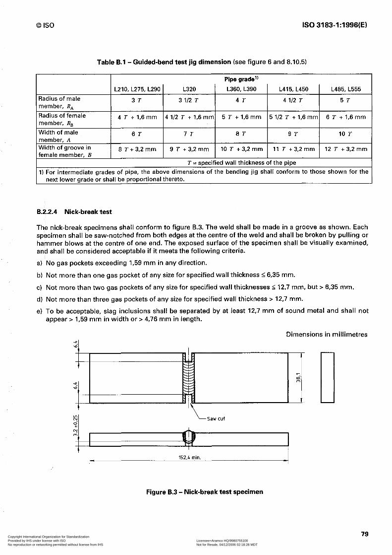
0 IS0 IS0 3183-1:1996(E)
Table B.l - Guided-bend test jig dimension (see figure 6 and 8.10.5)
Radius of male member, RA
Radius of female member, RB
Width of male member, A Width of groove in female member, B
Pipe grade’) L210, L275, L290 L320 L360, L390 L415, L450 L485, L555
3T 3 I/2 T 4T 4 l/2 T 5T
4 T + I,6 mm 4 l/2 T + I,6 mm 5 T + I,6 mm 5 l/2 T + I,6 mm 6 T + I,6 mm
6T 7T 8T 9T 10 T
8 T + 3,2 mm 9 T + 3,2 mm 10 T + 3,2 mm 11 T +3,2 mm 12 T + 3,2 mm
T = specified wall thickness of the pipe 1) For intermediate grades of pipe, the above dimensions of the bending jig shall conform to those shown for the
next lower grade or shall be proportional thereto.
B.2.2.4 Nick-break test
The nick-break specimens shall conform to figure B.3. The weld shall be made in a groove as shown. Each specimen shall be saw-notched from both edges at the centre of the weld and shall be broken by pulling or hammer blows at the centre of one end. The exposed surface of the specimen shall be visually examined, and shall be considered acceptable if it meets the following criteria.
a) No gas pockets exceeding I,59 mm in any direction.
b) Not more than one gas pocket of any size for specified wall thickness I6,35 mm.
c) Not more than two gas pockets of any size for specified wall thicknesses I 12,7 mm, but > 6,35 mm.
d) Not more than three gas pockets of any size for specified wall thickness > 12,7 mm.
e) To be acceptable, slag inclusions shall be separated by at least 12,7 mm of sound metal and shall not appear > 1,59 mm in width or > 4,76 mm in length.
Dimensions in millimetres
L Saw cut
152,4 min. 4
Figure 8.3 - Nick-break test specimen
79 Copyright International Organization for Standardization Provided by IHS under license with ISO Licensee=Aramco HQ/9980755100
Not for Resale, 04/12/2006 02:18:28 MDTNo reproduction or networking permitted without license from IHS
--``,,`,```````,`````,,,,,,`,`,-`-`,,`,,`,`,,`---

IS0 3183-1:1996(E) 0 IS0
B.3 Welding personnel performance qualification
6.3.1 Qualification
B.3.1.1 Each repair welder and operator is required to qualify. A repair welder or operator qualified on one grade category is qualified for any lower grade category provided the same welding process is used.
B.3.1.2 Testing
For qualification, a repair welder or operator shall produce welds which are acceptable in the following tests:
B.3.1.2.1 Film radiographic examination per 8.10.11.
B.3.1.2.2 Two transverse guided bend tests per B.2.2.3.
B.3.1.2.3 Two nick-break tests per B.2.2.4.
B.3.1.3 Test failures
If one or more of the tests in B.3.1.2 fail to meet the specified requirements, the welder or operator may make one additional qualification weld. If that weld fails one or more of the tests in B.3.1.2, the welder or operator is disqualified. No further retests shall be permitted until the welder has completed additional training.
B.3.2 Requalification
Requalification in accordance with B.3.1 is required under the following circumstances:
B.3.2.1 One year has elapsed since the last prior applicable qualification.
B.3.2.2 The individual has not been welding using qualified procedures for a period of three months.
B.3.2.3 There is reason to question the individual’s ability.
i
/ I /
!
I I
!
j I P , I i
i L i
i I
i
I
i
I
I ,
1 I i !
i
t
1
80 Copyright International Organization for Standardization Provided by IHS under license with ISO Licensee=Aramco HQ/9980755100
Not for Resale, 04/12/2006 02:18:28 MDTNo reproduction or networking permitted without license from IHS
--``,,`,```````,`````,,,,,,`,`,-`-`,,`,,`,`,,`---

0 IS0 IS0 3183-1:1996(E)
Annex C (normative)
Couplings
C.l Material
Couplings for grades L210 and L240 pipe shall be seamless and shall be made of a grade of material at least equal in mechanical properties to that of the pipe. Couplings for grade L175 pipe shall be seamless or welded, and shall be made of steel. By agreement between the interested parties, welded couplings may be supplied on pipe outside diameters 2 355,6 mm, if the couplings are properly marked.
C.2 Tensile test
A tensile test shall be made on each cast of steel from which couplings are produced, and the coupling manufacturer shall maintain a record of such tests. This record shall be open to inspection by the purchaser. If such test is made on finished couplings, either round specimens or strip specimens in accordance with IS0 6892, shall be used, at the option of the manufacturer.
C.3 Dimensions
Couplings shall conform to the dimensions and tolerances shown in table C.l and figure 1.
NOTE 22 Couplings covered by table C.l are applicable to either threaded or extra-strong threaded pipe.
C.4 Threading
Coupling threads, gauging practice and thread inspection shall conform to the requirements of the latest edition of IS0 10422. Couplings shall not be expanded to provide the required taper for threads.
C.5 Inspection
Couplings shall be free from blisters, pits, cinder marks and other defects which would impair the efficiency of the coupling or break the continuity of the thread.
81 Copyright International Organization for Standardization Provided by IHS under license with ISO Licensee=Aramco HQ/9980755100
Not for Resale, 04/12/2006 02:18:28 MDTNo reproduction or networking permitted without license from IHS
--``,,`,```````,`````,,,,,,`,`,-`-`,,`,,`,`,,`---

IS0 3183-1:1996(E) 0 IS0
II II 31 II 31 1 1 1 2 2 3 3 4 5 6 8 I( 1: 11 If It 2( 1
Table C.l - Coupling dimensions, masses and tolerances (see figure I)
Nominal size Outside diameter Minimum length designation of coupling
W” NL mm mm
8 14,3 27,0 '4 18,3 41,3 8 22,2 41,3 2 27,0 54,0 ,4 33,4 54,0
40,o 66,7 II4 52,2 69,8 I/2 55,9 69,8
73,0 73,0 I/2 85,7 104,8
101,6 108,O l/2 117,5 Ill,1
132,l 114,3 159,9 117,5 187,7 123,8 244,5 133,4
1 298,4 146,0 ! 355,6 155,6 ID 381,0 161,9 SD 431,8 171,4 SD 482,6 181,0 ID 533,4 193,7 ) Tolerance on outside diameter W: 2 1 %
Diameter of Width of bearing Calculated recess face coupling mass
Q b m mm kg
II,9 Or8 0,02 15,3 Or8 0,04 18,8 68 0,06 22,9 I,6 0,ll 28,3 I,6 0,15 35,0 2,4 0,25 43,8 2,4 0,47 49,9 2,4 0,41 62,7 32 0,84 75,4 48 I,48 91,3 4,8 I,86
104,o 4,8 2,69 116,7 6,4 3,45 143,7 64 4,53 170,7 64 5,87 221,5 64 IO,52 275,4 93 14,32 326,2 93 22,37 358,0 9,5 20,81 408,8 93 23,35 459,6 93 30,20 510,4 93 36,03
82 Copyright International Organization for Standardization Provided by IHS under license with ISO Licensee=Aramco HQ/9980755100
Not for Resale, 04/12/2006 02:18:28 MDTNo reproduction or networking permitted without license from IHS
--``,,`,```````,`````,,,,,,`,`,-`-`,,`,,`,`,,`---
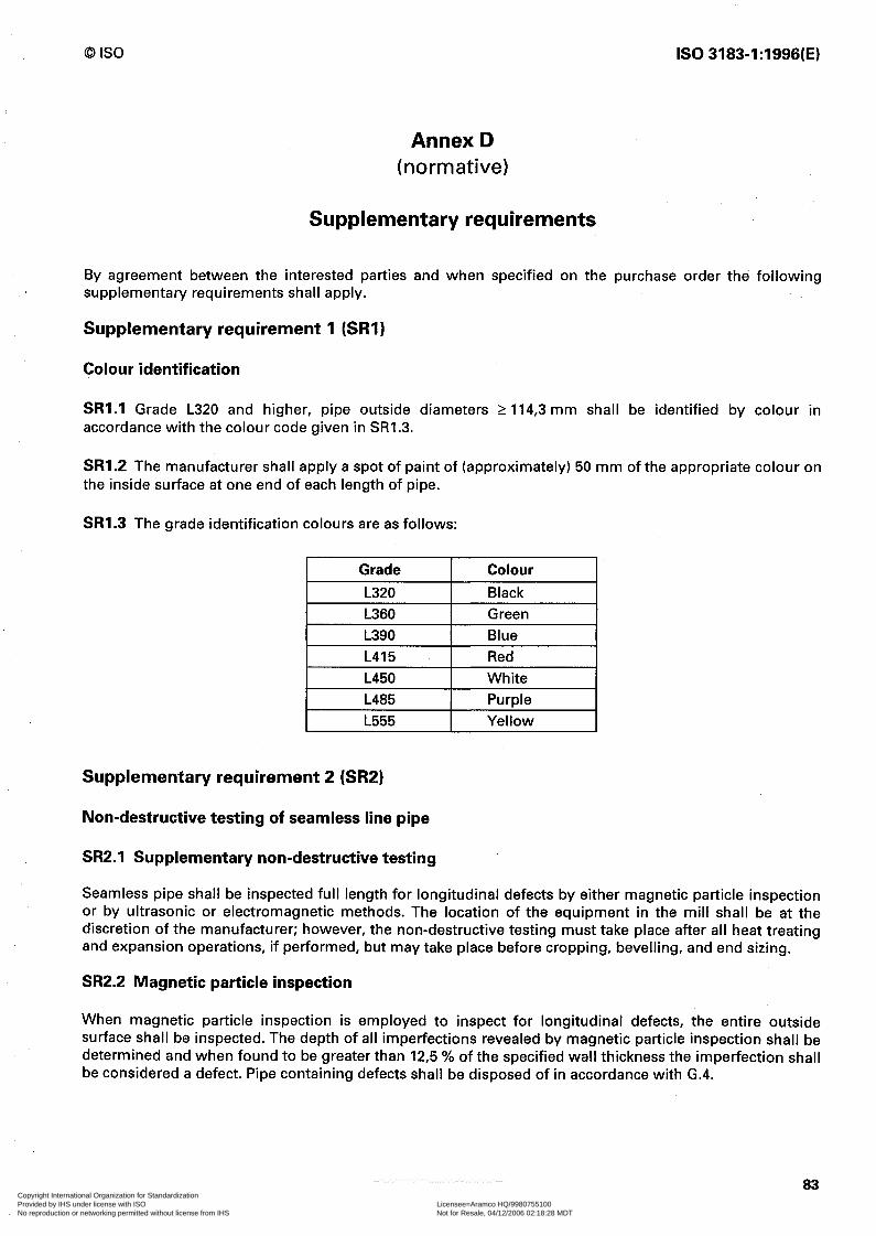
0 IS0 IS0 3183-1:1996(E)
Annex D (normative)
Supplementary requirements
By agreement between the interested parties and when specified on the purchase order the following supplementary requirements shall apply.
Supplementary requirement 1 (SRI)
Colour identification
SRI.1 Grade L320 and higher, pipe outside diameters 2 114,3 mm shall be identified by colour in accordance with the colour code given in SR1.3.
SRI.2 The manufacturer shall apply a spot of paint of (approximately) 50 mm of the appropriate colour on the inside surface at one end of each length of pipe.
SRI.3 The grade identification colours are as follows:
Grade Colour L320 Black L360 L390
Green Blue
L415 L450
Red White
I L485 I--- Purple I L555 Yellow
Supplementary requirement 2 (SR2)
Non-destructive testing of seamless line pipe
SR2.1 Supplementary non-destructive testing
Seamless pipe shall be inspected full length for longitudinal defects by either magnetic particle inspection or by ultrasonic or electromagnetic methods. The location of the equipment in the mill shall be at the discretion of the manufacturer; however, the non-destructive testing must take place after all heat treating and expansion operations, if performed, but may take place before cropping, bevelling, and end sizing.
SR2.2 Magnetic particle inspection
When magnetic particle inspection is employed to inspect for longitudinal defects, the entire outside surface shall be inspected. The depth of all imperfections revealed by magnetic particle inspection shall be determined and when found to be greater than 12,5 % of the specified wall thickness the imperfection shall be considered a defect. Pipe containing defects shall be disposed of in accordance with G-4.
83 Copyright International Organization for Standardization Provided by IHS under license with ISO Licensee=Aramco HQ/9980755100
Not for Resale, 04/12/2006 02:18:28 MDTNo reproduction or networking permitted without license from IHS
--``,,`,```````,`````,,,,,,`,`,-`-`,,`,,`,`,,`---
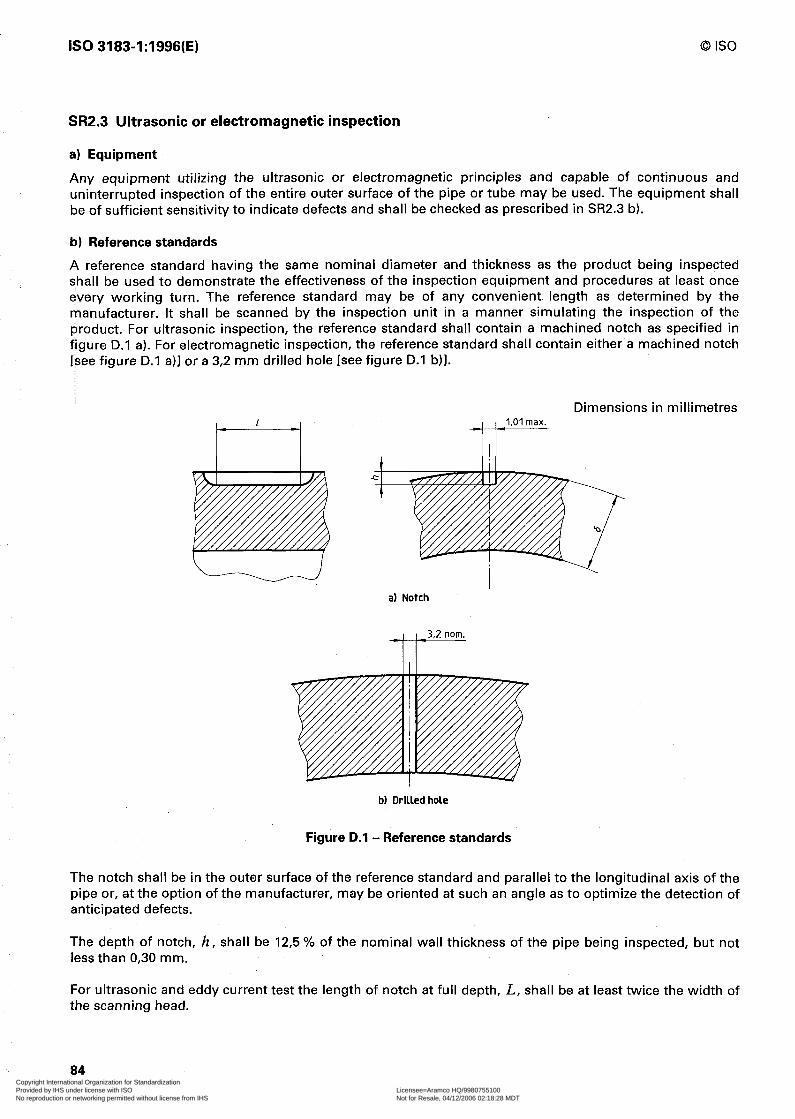
IS0 3183-1:1996(E) 0 IS0
SR2.3 Ultrasonic or electromagnetic inspection
a) Equipment
Any equipment utilizing the ultrasonic or electromagnetic principles and capable of continuous and uninterrupted inspection of the entire outer surface of the pipe or tube may be used. The equipment shall be of sufficient sensitivity to indicate defects and shall be checked as prescribed in SR2.3 b).
b) Reference standards
A reference standard having the same nominal diameter and thickness as the product being inspected shall be used to demonstrate the effectiveness of the inspection equipment and procedures at least once every working turn. The reference standard may be of any convenient length as determined by the manufacturer. It shall be scanned by the inspection unit in a manner simulating the inspection of the product. For ultrasonic inspection, the reference standard shall contain a machined notch as specified in figure D.l a). For electromagnetic inspection, the reference standard shall contain either a machined notch Isee figure D.l a)] or a 3,2 mm drilled hole [see figure D.l b)l.
Dimensions in millimetres
a) Notch
i b) Orllled hole
Figure D.l - Reference standards
The notch shall be in the outer surface of the reference standard and parallel to the longitudinal axis of the pipe or, at the option of the manufacturer, may be oriented at such an angle as to optimize,the detection of anticipated defects.
The depth of notch, h, shall be 12,5 % of the nominal wall thickness of the pipe being inspected, but not less than 0,30 mm.
For ultrasonic and eddy current test the length of notch at full depth, L, shall be at least twice the width of the scanning head.
84
k
Copyright International Organization for Standardization Provided by IHS under license with ISO Licensee=Aramco HQ/9980755100
Not for Resale, 04/12/2006 02:18:28 MDTNo reproduction or networking permitted without license from IHS
--``,,`,```````,`````,,,,,,`,`,-`-`,,`,,`,`,,`---

0 IS0 IS0 3183-1:1996(E)
For diverted flux the length of notch shall be as required by the equipment design to provide a reproducible signal when the reference standard is passed through the equipment at the inspection line speed for the pipe being inspected. Three passes through the equipment shall be required to insure reproducibility.
The 3,2 mm hole shall be drilled radially through the wall of the reference standard. The inspection equipment shall be adjusted to produce a well-defined indication when the reference standard is scanned by the inspection unit.
c) Acceptance limits
Any imperfection that produces a signal greater than the signal received from the reference standard shall be considered a defect unless it can be demonstrated by the manufacturer that the imperfection does not exceed the provisions of G.3. Pipe containing defects shall be given one of the dispositions specified in G.4.
NOTES
23 The reference standards defined above are convenient standards for calibration of non-destructive testing equipment. The dimensions of these standards should not be construed as the minimum size imperfection detectable by such equipment.
24 Reference standards other than the specific notch described above may be used by agreement between the interested parties.
SR2.4 Marking
Pipe non-destructively inspected in accordance with this supplementary requirement shall be marked SR2.
Supplementary requirement 3 (SR3)
Fracture toughness testing (Charpy) of pipe outside diameters 2 114,3 mm
SR3.1 The manufacturer is responsible for the performance of Charpy-V-notch tests in accordance with ASTM A 370. Either one or both toughness criteria (A-shear area or B-absorbed energy) may be specified under this supplementary requirement.
SR3.2 The following applies to all specified limits and observed values to be used in connection with this SR3.
For purposes of determining conformity with this SR3, an observed value shall be rounded off to the nearest whole number in accordance with the rounding off method of ASTM A 29. Further, limiting values as specified or calculated under this SR3 shall be expressed as whole numbers rounded, if necessary.
SR3.3 Flattening of the pipe wall is not permitted.
SR3.4 When the wall thickness does not permit machining full size 10 mm by IO mm specimens the largest size possible, of either 213 size or l/2 size shall be substituted (see table D.1). The selection of subsize specimens for pipe whose size permits full size specimens is permissible by agreement between the interested parties.
A. Shear area
SR3A.l Three transverse specimens shall be taken from one length of pipe from each lot of 100 lengths per cast produced.
85 Copyright International Organization for Standardization Provided by IHS under license with ISO Licensee=Aramco HQ/9980755100
Not for Resale, 04/12/2006 02:18:28 MDTNo reproduction or networking permitted without license from IHS
--``,,`,```````,`````,,,,,,`,`,-`-`,,`,,`,`,,`---

IS0 3183-1:1996(E) 0 IS0
The requirements of this SR3 are limited to pipe sizes and thickness from which a l/2 size specimen may be secured.
The specimen shall be oriented circumferentially from a location 90” from the weld, with the axis of the notch oriented through the pipe wall thickness as shown in figure D.2.
SR3A.2 The specimens shall be tested at IO “C or at a lower temperature as specified by the purchaser. The average shear value of the fracture appearance of the three specimens shall not be less than 60 % and the all-cast average for each order per diameter size and grade shall not be less than 80 %.
Table D.l - Minimum wall thickness for transverse Charpy V-notch specimens
Outside diameter
mm 114,3 141,3 168,3 219,l 273,l 323,9 355,6 406,4 457,0 508,O 559,0 610,O 660,O 711,0 762,0 813,0 864,0 914,0 965,0
1016,O 1067,O 1118,0 1168,O 1219,0 1321,0 1422,0 1524,0 1626,0
full size specimen mm 17,06 15,60 14,68 13,51 12,80 12,37 12,14 II,89 II,66 II,51 II,35 II,25 II,15 II,07 1 I,00 IO,95 IO,90 IO,85 IO,80 IO,74 IO,72 IO,70 IO,64 IO,62 IO,59 IO,54 IO,52 IO,46
Minimum wall thickness for 2/3 size specimen l/2 size specimen
mm mm 13,74 12,05 12,27 IO,59 II,30 9,60 IO,19 8,51
9,47 7,80 8,94 7,37 8,81 7,14 8,56 6,88 8,33 6,65 8,20 6,50 8,03 6,35 7,92 6,25 7,82 6,15 7,75 6,07 7,67 5,99 7,62 5,94 7,57 5,89 7,52 5,84 7,47 5,79 7,42 5,74 7,39 5,72 7,37 5,69 7,32 5,64 7,30 5,61 7,26 5,59 7,21 5,54 7,19 5,51 7,14 5,46
SR3A.3 If the average of the three specimens from one cast does not meet the requirement of 60 % shear, the manufacturer may elect to repeat the tests on specimens cut from two additional lengths of pipe from the same cast. If such specimens conform to the specified requirements, all the lengths in the cast shall be accepted except the length initially selected for test. If any of the re-test specimens fail to pass this specified re-test requirement, the manufacturer may elect to test specimens cut from the individual lengths remaining in the cast.
SR3A.4 The average shear value for a cast shall be the average of the original three specimens if this is 60 % or more; the combined average of the re-test specimens, provided the average of each group of three
86 Copyright International Organization for Standardization Provided by IHS under license with ISO Licensee=Aramco HQ/9980755100
Not for Resale, 04/12/2006 02:18:28 MDTNo reproduction or networking permitted without license from IHS
--``,,`,```````,`````,,,,,,`,`,-`-`,,`,,`,`,,`---

0 IS0 IS0 3183-1:1996(E)
specimens is 60 % or more; or, in the event individual lengths are tested, the combined average of all groups of three specimens that meet 60 %. The all-cast average value is the combined average of the value established for each cast.
SR3A.5 If the all-cast average of the order does not meet the requirement of 80 % shear, the manufacturer shall be responsible for replacement of such casts as may be necessary to bring the average shear area up to 80 %.
SR3A.6 Alternatively, the manufacturer may elect to test two or more additional lengths from one or more of the casts. In determining the new cast average, the original test values may be discarded if the pipe length represented is rejected or the three or more individual values averaged. In any case, the new test values shall be incorporated into the value for the cast.
SR3A.7 Specimens showing material defects or defective preparation, whether observed before or after breaking, may be discarded and replacements shall be considered as original specimens.
SR3A.8 Marking Pipe tested in accordance with this supplementary requirement shall be marked to indicate the type of test and the test temperature. Temperatures below 0 “C shall be preceded by the letter M (see note 25).
Example at 0 “C: SRSA-OC
Example at - 40 “C: SR3A-M40C
B. Absorbed energy
SR3B.l The fracture toughness of the pipe shall be determined using Charpy V-notch impact test specimens in accordance with the latest edition of ASTM A 370 and the requirements of SR3A.1, except that test frequency shall be as indicated in SR3B.2. Purchaser shall specify, in whole numbers, both the test temperature and the minimum average absorbed energy for full size specimens.
Specimens used for shear area determination according to SRSA, may be additionally used for the determination of absorbed energy.
SR3B.2 Three transverse specimens shall be taken from one length of pipe from each lot of at maximum 100 lengths. In no case a lot shall contain more than one cast.
SR3B.3 For acceptance, the average absorbed energy of the 3 individual specimens from a length shall not be less than the full size value specified by the purchaser. In addition, the lowest individual reading of the three specimens shall not be less than 75 % of the specified value. When subsize specimens are used, the individual readings and the average of the three readings are divided by the fractional specimen size and compared with the full size acceptance criteria.
SR3B.4 Specimens showing material defects or defective preparations, whether observed before or after breaking, may be discarded and replacements shall be considered original specimens.
In the event a set of test specimens fails to meet the acceptance criteria, the manufacturer may elect to replace the lot of material involved or alternatively to test two or more lengths from the same lot. If both of the new tests meet the acceptance criteria, then all pipe in that lot with the exception of the original selected length shall be considered to meet the requirement. Failure of either of the two additional tests shall require testing of each length in the lot for acceptance.
SR3B.5 Pipe complying with this supplementary requirement shall be marked to indicate the type of test, the specified (full size) minimum average absorbed energy and the test temperature.
Example for 40 J at 0 “C: SR3B-40J-OC
87 Copyright International Organization for Standardization Provided by IHS under license with ISO Licensee=Aramco HQ/9980755100
Not for Resale, 04/12/2006 02:18:28 MDTNo reproduction or networking permitted without license from IHS
--``,,`,```````,`````,,,,,,`,`,-`-`,,`,,`,`,,`---

IS0 3183-1:1996(E) 0 IS0
Example for 27 J at - 40 “C: SR3B-27J-M40C
Example for both SR3A and SRSB 27 J at - 40 “C: SR3AB-27J-M40C
NOTE 25 M signifies a minus temperature (see SR3A.8 Marking).
Supplementary requirement 4 (SR4)
Drop weight tear (DW) testing on welded pipe with outside diameters 2 508 mm, grade L360 or higher
SR4.1 Fracture toughness of pipe with outside diameters 2 508 mm, grade L360 and higher, shall be determined by the manufacturer using drop weight tear test in accordance with the following requirements:
SR4.2 Two transverse specimen shall be taken from one length of pipe from each cast supplied in the order. The specimens shall be oriented circumferentially from a location 90” from the weld with the axis of the notch oriented through the pipe wall thickness as shown in figure D.2. The specimens shall be tested at 10 “C or at a lower temperature as specified by the purchaser.
SR4.3 The test specimens, testing procedures, and rating of the specimens shall be in accordance with the latest edition of API RP 5L3.
SR4.4 At least 80 % of the casts shall exhibit a fracture appearance shear area of 40 % or more for the specified test temperature.
NOTE 26 Due to manufacturing difficulties encountered with thicker materials, pipe producers may not be able to offer materials in all grades that meet this requirement.
SR4.5 In the event the average value of the two specimens from the length selected to represent the cast is less than 40 %, the manufacturer may elect to establish the cast average by testing two specimens from each of two or more additional lengths of pipe in the cast. In establishing the new cast average, the manufacturer may elect to employ the combined average of the three or more tests; or to discard the first test, reject the pipe from which it was taken, and employ the combined average of the two or more additional tests. Alternatively, the manufacturer may elect to test all the pipe in the cast, in which case 80 % or more of the lengths tested and applied to the order must exhibit an average of 40 % or more shear.
SR4.6 Specimens showing material defects or defective preparation, whether observed before or after breaking, may be discarded and replacements shall be considered as original specimens.
SR4.7 The manufacturer shall be responsible for replacement of such casts as may be necessary to meet the above requirements.
SR4.8 Marking
Pipe tested in accordance with this supplementary requirements shall be marked to indicate the type of test and the testing temperature.
Example: SR40C
88 Copyright International Organization for Standardization Provided by IHS under license with ISO Licensee=Aramco HQ/9980755100
Not for Resale, 04/12/2006 02:18:28 MDTNo reproduction or networking permitted without license from IHS
--``,,`,```````,`````,,,,,,`,`,-`-`,,`,,`,`,,`---
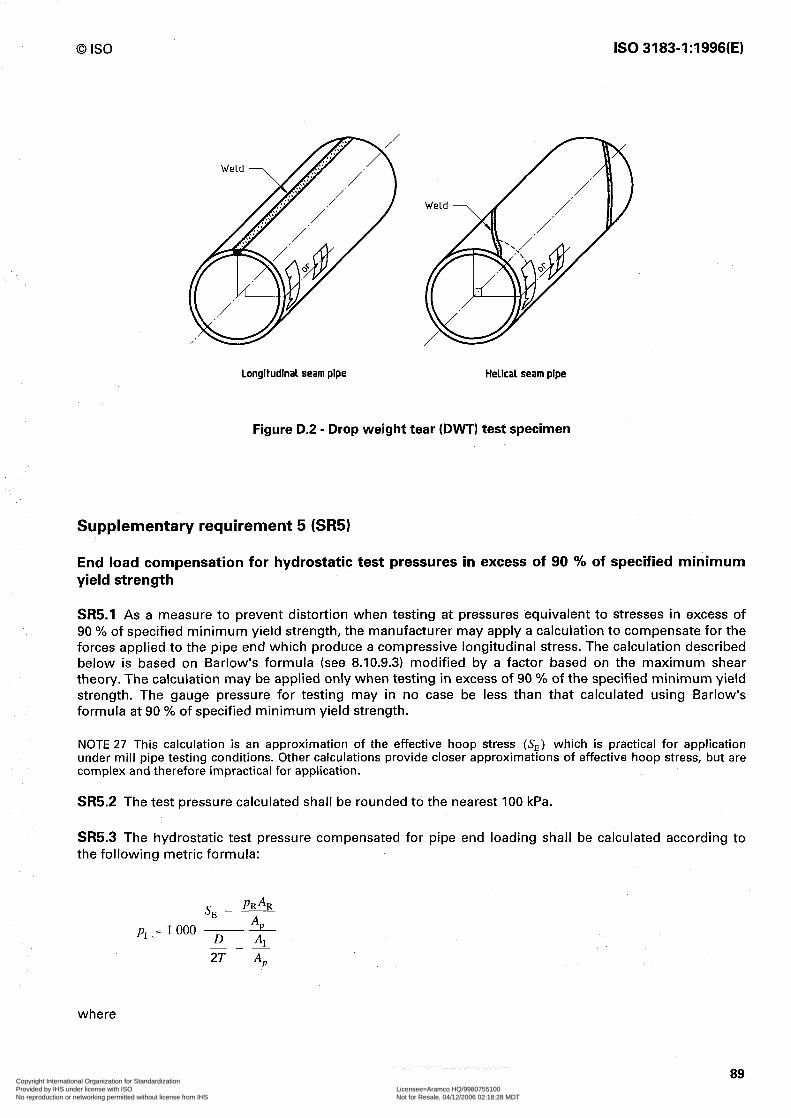
0 IS0 IS0 3183-1:1996(E)
Longitudinal seam pipe Helical seam pipe
Figure D.2 - Drop weight tear (DWT) test specimen
Supplementary requirement 5 (SR5)
End load compensation for hydrostatic test pressures in excess of 90 % of specified minimum yield strength
SR5.1 As a measure to prevent distortion when testing at pressures equivalent to stresses in excess of 90 % of specified minimum yield strength, the manufacturer may apply a calculation to compensate for the forces applied to the pipe end which produce a compressive longitudinal stress. The calculation described below is based on Barlow’s formula (see 8.10.9.3) modified by a factor based on the maximum shear theory. The calculation may be applied only when testing in excess of 90 % of the specified minimum yield strength. The gauge pressure for testing may in no case be less than that calculated using Barlow’s formula at 90 % of specified minimum yield strength.
NOTE 27 This calculation is an approximation of the effective hoop stress (S,) which is practical for application under mill pipe testing conditions. Other calculations provide closer approximations of effective hoop stress, but are complex and therefore impractical for application.
SR5.2 The test pressure calculated shall be rounded to the nearest 100 kPa.
SR5.3 The hydrostatic test pressure compensated for pipe end loading shall be calculated according to the following metric formula:
s _ PUAU E A
p1 = 1000 D AI ---
2T A,,
where
89 Copyright International Organization for Standardization Provided by IHS under license with ISO Licensee=Aramco HQ/9980755100
Not for Resale, 04/12/2006 02:18:28 MDTNo reproduction or networking permitted without license from IHS
--``,,`,```````,`````,,,,,,`,`,-`-`,,`,,`,`,,`---

IS0 3183-1:1996(E) 0 IS0
AI A, AR
PI PR
SE
D T
is the internal cross-sectional area of pipe, in square millimetres; is the cross-sectional area of pipe wall, in square millimetres; is the cross-sectional area of ram, in square millimetres; is the hydrostatic test pressure, in kilopascals; is the internal pressure on end sealing ram, in kilopascals; is the effective hoop stress, in megapascals, equal to a percentage of the specified minimum yield strength; is the specified outside diameter, in millimetres; is the specified wall thickness, in millimetres.
SR5.4 The above formula may be manipulated algebraically to provide calculation in other terms appropriate to the manufacturer’s testing facility.
SR5.5 Appropriate techniques for the control of effective hoop stress based on measurements of internal pipe and ram pressures vary according to hydrotester system design. The manufacturer shall provide a control technique appropriate to his installation.
Supplementary requirement 6 (SR6)
Test certificates for line pipe
SR6.1 The manufacturer shall deliver a certificate (in accordance with IS0 10474 - 3.1B) where this part of IS0 3183 is stated and where the following data, as applicable for each item for which this SR6 is specified on the purchase order are given.
a) Specified diameter, wall thickness, grade, process of manufacture, and type of heat treatment
b) Chemical analyses (cast, product, control, and recheck) showing the weight percent of all elements whose limits or reporting requirements are set in this specification
c) Test data for all tensile tests required by this specification, including yield strength, ultimate tensile strength, elongation. The type, size and orientation of specimens shall be shown.
d) Fracture toughness test results (including test type and criteria, and the size, location and orientation of specimen) where such testing is specified by the purchaser.
e) Minimum hydrostatic test pressure and duration.
f) For welded pipe for which non-destructive inspection of the weld seam is required by this part of IS0 3183, the method of non-destructive inspection employed (radiological, ultrasonic, electromagnetic, and/or magnetic particle) and the type and size of all penetrameters and/or reference standards used.
g) For seamless pipe for which non-destructive inspection (see SR2) is specified by the purchaser, the method of inspection employed (ultrasonic, electromagnetic, or magnetic particle) and the type and size of the reference standard used.
h) For electric-welded pipe, the minimum temperature for heat treatment of the weld seam. Where such heat treatment is not performed, “No seam heat treatment” shall be stated on the certificate.
i) Results of any supplemental testing required by the purchaser.
SR6.2 The manufacturer shall establish and follow procedures for maintaining cast and lot identity of all pipes covered by this SR6. The procedures shall provide means for tracing any length of pipe or coupling to the proper cast and lot, and to all applicable chemical and mechanical test results.
90 Copyright International Organization for Standardization Provided by IHS under license with ISO Licensee=Aramco HQ/9980755100
Not for Resale, 04/12/2006 02:18:28 MDTNo reproduction or networking permitted without license from IHS
--``,,`,```````,`````,,,,,,`,`,-`-`,,`,,`,`,,`---
0 IS0 IS0 3183-1:1996(E)
Supplementary requirement 7 (SR7)
Non-destructive testing of welds in electric-welded pipe
SR7.1 Supplementary non-destructive testing
The weld in electric-welded pipe shall be inspected full length for surface and subsurface defects by either ultrasonic or electromagnetic methods. The location of the equipment in the mill shall be at the discretion of the manufacturer; however, the non-destructive testing must take place after all heat treating, hydrostatic testing, expansion and rotary straightening operations, if performed, but may take place before cropping, bevelling, and sizing of pipe.
SR7.2 Equipment and reference standards
The ultrasonic or electromagnetic inspection equipment requirements are given in 8.10.11.3.1 and the reference standards are described in 8.10.11.3.2. Details of the specific techniques (e.g. method, reference standards, transducer properties, sensitivity, etc.) shall be agreed upon between the interested parties for the implementation of this supplementary requirement.
SR7.3 Acceptance limits and EMI inspection
Table 22 gives the height of acceptance limit signals in percent of height of signals produced by reference standards. An imperfection that produces a signal greater than the acceptance limit signal given in table 22 shall be classified as defect.
SR7.4 Disposition
Defects shall be disposed of in accordance with G.4.a), G.4.c), and G.4.d). Repair by welding is not permitted. If a defect is removed by grinding, the ground area shall be reinspected by the same method originally used.
SR7.5 Marking
Pipe non-destructively inspected in accordance with this SR7 shall be marked SR7.
Supplementary requirement 8 (SR8)
Carbon equivalent
SR8.1 For pipe grades up to L485 inclusive, the carbon equivalent (CE 1 calculated using product analysis and the following formula shall not exceed 0,43 %:
cE=c +7+ Mn Cr+Mo+V + Ni+Cu
in % 5 15
SR8.2 The elements analysed for product analysis shall include all elements contained in the carbon equivalent formula.
91 Copyright International Organization for Standardization Provided by IHS under license with ISO Licensee=Aramco HQ/9980755100
Not for Resale, 04/12/2006 02:18:28 MDTNo reproduction or networking permitted without license from IHS
--``,,`,```````,`````,,,,,,`,`,-`-`,,`,,`,`,,`---
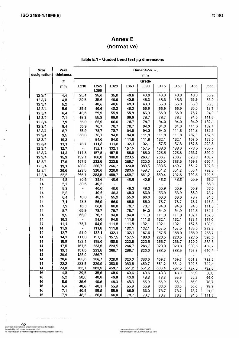
IS0 3183-1:1996(E) 0 IS0
Size Wall Dimension A, designation thickness mm
12 314 4,4 12 314 4,8 12 314 52 12 314 56 12 314 64 12 314 7,l 12 314 7,9 12 314 84 12 314 8,7 12 314 93 12 314 IO,3 12 314 II,1 12 314 12,7 12 314 14,3 12 314 15,9 12 314 17,5 12 314 19,l 12 314 20,6 12 314 22,2
14 4,8 14 52 14 5,3 14 5,6 14 64 14 7,l 14 73 14 8,7 14 93 14 IO,3 14 II,1 14 II,9 14 12,7 14 14,3 14 15,9 14 17,5 14 19,l 14 20,6 14 20,6 14 22,2 14 23,8 16 4,8 16 5,2 16 56 16 6,4 16 7,l 16 73
T mm
Annex E (normative)
Table E.l - Guided bend test jig dimensions
L210
25,4 30,5
35,6 40,6 48,3 55,9 55,9 55,9 66,O
78,7
Ill,8 132,l 157,5 188,O 223,5 266,7
30,5 30,5
40,6 48,3 48,3 55,9 66,O
78,7
94,0 Ill,8 132,l 157,5 157,5 188,O 188,O 223,5 266,7
30,5 30,5 35,6 40,6 40,6 483
L245 L290 35,6 35,6 40,6 40,6 55,9 55,9 66,O 78,7 78,7 78,7 94,0
Ill,8 132,l 157,5 188,O 223,5 266,7 320,O 383,5
35,6 40,6 40,6 40,6 48,3 55,9 66,O 78,7 78,7 94,0 94,0
Ill,8 132,l 157,5 188,O 223,5 223,5 266,7 266,7 320,O 383,5
35,6 40,6 40,6 48,3 55,9 66.0
L320 L360 Grade L390 L415 L450 L485 L555
35,6 40,6 40,6 40,6 40,6 48,3 40,6 40,6 48,3 48,3 48,3 55,9 40,6 48,3 48,3 55,9 55,9 55,9 48‘3 48,3 55,9 55,9 55,9 66,O 55,9 55,9 66,O 66,O 66,O 78,7 66,O 66,O 78,7 78,7 78,7 94,0 66,O 78,7 78,7 94,0 94,0 94,0 78,7 78,7 94,0 94,0 94,0 Ill,8 78,7 94,0 94,0 94,0 Ill,8 Ill,8 94,0 94,0 Ill,8 Ill,8 Ill,8 132,l 94,0 Ill,8 Ill,8 132,l 132,l 157,5
Ill,8 132,l 132,l 157,5 157,5 157,5 132,l 157,5 157,5 188,O 188,O 223,5 157,5 188,O 188,O 223,5 223,5 266,7 188,O 223,5 266,7 266,7 266,7 320,O 223,5 266,7 320,O 320,O 383,5 459,7 266,7 320,O 383,5 383,5 459,7 551,2 320,O 383,5 459,7 551,2 551,2 550,4 459,7 459,7 551,2 660,4 792,5 792,5
40,6 40,6 40,6 48,3 48,3 55,9
40,6 48,3 48,3 55,9 55,9 55,9 48,3 48,3 55,9 55,9 55,9 66,O 55,9 55,9 66,O 66,O 66,O 78,7 66,O 66,O 66,O 78,7 78,7 78,7 66,O 78,7 78,7 94,0 94,0 94,0 78,7 78,7 94,0 94,0 94,0 Ill,8 94,0 94,0 Ill,8 Ill,8 Ill,8 132,l 94,0 Ill,8 Ill,8 132,l 132,l 132,l
Ill,8 Ill,8 132,l 132,l 132,l 157,5 Ill,8 132,l 132,l 157,5 157,5 188,O 132,l 132,l 157,5 157,5 188,O 188,O 157,5 157,5 188,O 223,5 223,5 223,5 188,O 223,5 223,5 266,7 266,7 320,O 223,5 266,7 266,7 320,O 320,O 383,5 266,7 266,7 320,O 383,5 383,5 459,7
55,9 66,O 66,O 78,7 94,0
Ill,8 132,l 132,l 132,l 157,5 188,O 223,5 266,7 320,O 459,7 660,4 792,5 792,5 792,5
66,O 66,O 66,O 78,7 94,0
Ill,8 Ill,8 132,l 157,5 188,O 188,O 223,5 266,7 320,O 383,5 459,7 660,4
320,O 320,O 383,5 459,7 459,7 551,2 792,5 383,5 383,5 459,7 551,2 551,2 792,5 792,5 459,7 551,2 551,2 660,4 792,5 792,5 792,5
40,6 40,6 40,6 48,3 48,3 55,9 66,O 40,6 40,6 48,3 48,3 55,9 55,9 66,O 48,3 48,3 55,9 55,9 55,9 66,O 78,7 55,9 55,9 55,9 66,O 66,O 66,O 78,7 55,9 66,O 66,O 78,7 78,7 78,7 94,0 66,O 78.7 787 78,7 767 94,o Ill,8
92 Copyright International Organization for Standardization Provided by IHS under license with ISO Licensee=Aramco HQ/9980755100
Not for Resale, 04/12/2006 02:18:28 MDTNo reproduction or networking permitted without license from IHS
--``,,`,```````,`````,,,,,,`,`,-`-`,,`,,`,`,,`---

0 IS0 IS0 3183-1:1996(E)
Table E.l - (continued
Size Wall Dimension A, lesignation thickness mm
T mm L210 L245
L290 66,O 78,7 94,0 94,0
Ill,8 Ill,8 132,l 157,5 188,O 223,5 266,7 266,7 320,O 383,5 459,7 551,2
35,6 40,6 48,3 55,9 66,O 66,O 78,7 78,7 94,0
Ill,8 Ill,8 132,l 157,5 188,O 188,O 223,5 266,7 320,O 320,O 383,5 459,7 459,7 551,2
40,6 48,3 55,9 66,O 66,O 78,7 78,7 94,0 94,0
Ill,8 132,l 157,5
L320 L360 Grade L390 L415 L450 L485 L555
16 8,7 16 93 16 IO,3 16 II,1 16 II,9 16 12,7 16 14,3 16 15,9 16 17.5 16 19,l 16 20,6 16 22,2 16 25,4 16 27,0 16 28,6 16 30,2 18 4,8 18 56 18 64 18 7,l 18 73 18 8,7 18 93 18 IO,3 18 11.1 18 II,9 18 12,7 18 14,3 18 15,9 18 17,5 18 19,l 18 20,6 18 22,2 18 23,8 18 25.4 18 27,0 18 28,6 18 30,2 18 31.8 20 5,6 20 6,4 20 7,l 20 73 20 67 20 93 20 IO,3 20 II,1 20 II,9 20 12,7 20 14,3 20 15.9
55,9 66,O
78,7
94,0 Ill,8 Ill,8 132,l 157,5 188,O 188,O 223,5 266,7 266,7 320,O
25,4 35,6 40,6 40,6 48,3 55,9 55,9
78,7
78,7 94,0
Ill,8 132,l 157,5 157,5 188,O 223,5 223,5 266,7 266,7 320,O 383,5
30,5 40,6 40,6 48,3 55,9 55,9
66,O
78,7 94,0
Ill,8
78,7 78,7 94,0 94,0 94,0 Ill,8 78,7 94,0 94,0 Ill,8 Ill,8 Ill,8 94,0 94,0 Ill,8 Ill,8 132,l 132,l
Ill,8 Ill,8 132,l 132,l 132,l 157,5 Ill,8 132,l 132,l 132,l 157,5 157,5 132,l 132,l 157,5 157,5 157,5 188,O 157,5 157,5 188,O 188,O 188,O 223,5 157,5 188,O 223,5 223,5 223,5 266,7 188,O 223,5 266,7 266,7 266,7 320,O 223,5 266,7 266,7 320,O 320,O 383,5 266,7 320,O 320,O 383,5 383,5 459,7 320,O 320,O 283,5 459,7 459,7 551,2 383,5 383,5 459,7 551,2 551,2 660,4 383,5 459,7 551,2 564,2 564,2 792,5 459,7 551,2 564,2 792,5 792,5 792,5 551,2 564,2 792,5 792,5 792,5 792,5
35,6 40,6 40,6 48,3 48,3 48,3 40,6 48,3 48,3 55,9 55,9 55,9 48,3 55,9 55,9 66,O 66,O 66,O 55,9 66,O 66,O 66,O 78,7 78,7 66,O 66,O 78,7 78,7 78,7 94,0 78,7 78,7 94,0 94,0 94,0 Ill,8 78,7 94,0 94,0 94,0 Ill,8 Ill,8 94,0 94,0 Ill,8 Ill,8 Ill,8 132,l 94,0 Ill,8 Ill,8 132,l 132,l 132,l
Ill,8 Ill,8 132,l 132,l 132,l 157,5 Ill,8 132,l 132,l 157,5 157,5 157,5 132,l 157,5 157,5 188,O 188,O 188,O 157,5 188,O 188,O 223,5 223,5 223,5 188,O 188,O 223,5 223,5 266,7 266,7 223,5 223,5 266,7 266,7 320,O 320,O 223,5 266,7 320,O 320,O 320,O 383,5 266,7 320,O 320,O 383,5 383,5 459,7 320,O 383,5 383,5 459,7 459,7 551,2 383,5 383,5 459,7 551,2 551,2 660,4 383,5 459,7 551,2 551,2 660,4 792,5 459,7 551,2 660,4 660,4 792,5 792,5 551,2 660,4 792,5 792,5 792,5 792,5 660,4 660,4 792,5 792,5 792,5 792,5
40,6 48,3 48,3 55,9 55,9 55,9 48,3 55,9 55,9 66,O 66,O 66,O 55,9 66,O 66,O 66,O 78,7 78,7 66,O 66,O 78,7 78,7 78,7 94,0 78,7 78,7 78,7 94,0 94,0 94,0 78,7 94,0 94,0 94,0 94,0 Ill,8 94,0 94,0 Ill,8 Ill,8 Ill,8 132,l 94,0 Ill,8 Ill,8 Ill,8 132,l 132,l
Ill,8 Ill,8 132,l 132,l 132,l 157,5 Ill,8 132,l 132,l 132,l 157,5 157,5 132,l 157,5 157,5 157,5 188,O 188,O 157,5 157,5 188,O 188,O 188,O 223,5
132,l 157,5 157,5 188,O 188,O 223,5 266,7 320,O 383,5 551,2 660,4 792,5 792,5 792,5 792,5 792,5
66,O 78,7 94,0
Ill,8 132,l 132,l 157,5 188.0 188,O 223,5 266,7 320,O 383,5 459,7 551,2 662,9 792,5 792,5 792,5 792.5 792,5 792,5
66,O 78,7 94,0
Ill,8 Ill,8 132,l 157,5 157,5 188,O 188,O 223,5 266,7
93 Copyright International Organization for Standardization Provided by IHS under license with ISO Licensee=Aramco HQ/9980755100
Not for Resale, 04/12/2006 02:18:28 MDTNo reproduction or networking permitted without license from IHS
--``,,`,```````,`````,,,,,,`,`,-`-`,,`,,`,`,,`---
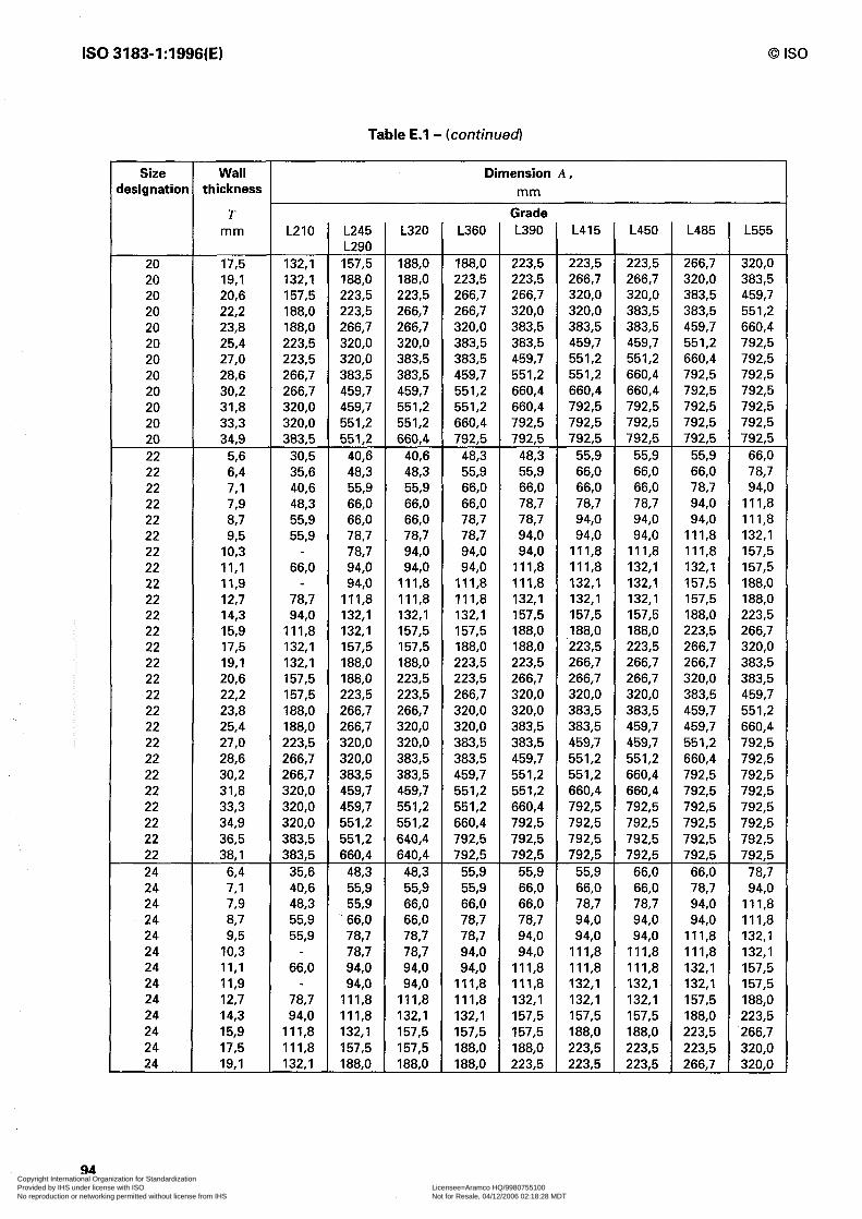
IS0 3183-1:1996(E)
Table E.l - (continued)
0 IS0
Size Wall Dimension A, iesignatior thickness mm
T mm L210 L245
L290 157,5 188,O 223,5 223,5 266,7 320,O 320,O 383,5 459,7 459,7 551,2 551,2
40,6 48,3 55,9 66,O 66,O 78,7 78,7 94,0 94,0
Ill,8 132,l 132,l 157,5 188,O 188,O 223,5 266,7 266,7 320,O 320,O 383,5 459,7 459,7 551,2 551,2 660,4
48,3 55,9 55,9
_ 66,O 78,7 78,7 94,0 94,0
Ill,8 Ill,8 132,l 157,5 188,O
L320 L360 Grade L390 L415 L450 L485 L555
20 17,5 20 19,l 20 20,6 20 22,2 20 23,8 20 25,4 20 27,0 20 28,6 20 30,2 20 31,8 20 33,3 20 34,9 22 56 22 64 22 7,l 22 73 22 87 22 93 22 IO,3 22 II,1 22 II,9 22 12,7 22 14,3 22 15,9 22 17,5 22 19,l 22 20,6 22 22,2 22 23,8 22 25,4 22 27,0 22 28,6 22 30,2 22 31,8 22 33,3 22 34,9 22 36,5 22 38,l 24 6,4 24 7,l 24 73 24 8,7 24 93 24 IO,3 24 II,1 24 II,9 24 12,7 24 14,3 24 15,9 24 17,5 24 19,l
132,l 132‘1 157,5 188,O 188,O 223,5 223,5 266,7 266,7 320,O 320,O 383,5
30,5 35,6 40,6 48,3 55,9 55,9
66,O
78,7 94,0
Ill,8 132,l 132,l 157,5 157,5 188,O 188,O 223,5 266,7 266,7 320,O 320,O 320,O 383,5 383,5
35,6 40,6 48,3 55,9 55,9
66,O
78,7 94,0
Ill,8 Ill,8 132,l
188,O 188,O 223,5 223,5 223,5 266,7 320,O 188,O 223,5 223,5 266,7 266,7 320,O 383,5 223,5 266,7 266,7 320,O 320,O 383,5 459,7 266,7 266,7 320,O 320,O 383,5 383,5 551,2 266,7 320,O 383,5 383,5 383,5 459,7 660,4 320,O 383,5 383,5 459,7 459,7 551,2 792,5 383,5 383,5 459,7 551,2 551,2 660,4 792,5 383,5 459,7 551,2 551,2 660,4 792,5 792,5 459,7 551,2 660,4 660,4 660,4 792,5 792,5 551,2 551,2 660,4 792,5 792,5 792,5 792,5 551,2 660,4 792,5 792,5 792,5 792,5 792,5 660,4 792,5 792,5 792,5 792,5 792,5 792,5
40,6 48,3 48,3 55,9 55,9 55,9 66,O 48,3 55,9 55,9 66,O 66,O 66,O 78,7 55,9 66,O 66,O 66,O 66,O 78,7 94,0 66,O 66,O 78,7 78,7 78,7 94,0 Ill,8 66,O 78,7 78,7 94,0 94,0 94,0 Ill,8 78,7 78,7 94,0 94,0 94,0 Ill,8 132,l 94,0 94,0 94,0 Ill,8 Ill,8 Ill,8 157,5 94,0 94,0 Ill,8 Ill,8 132,l 132,l 157,5
Ill,8 Ill,8 Ill,8 132,l 132,l 157,5 188,O Ill,8 Ill,8 132,l 132,l 132,l 157,5 188,O 132,l 132,l 157,5 157,5 157,5 188,O 223,5 157,5 157,5 188,O 188,O 188,O 223,5 266,7 157,5 188,O 188,O 223,5 223,5 266,7 320,O 188,O 223,5 223,5 266,7 266,7 266,7 383,5 223,5 223,5 266,7 266,7 266,7 320,O 383,5 223,5 266,7 320,O 320,O 320,O 383,5 459,7 266,7 320,O 320,O 383,5 383,5 459,7 551,2 320,O 320,O 383,5 383,5 459,7 459,7 660,4 320,O 383,5 383,5 459,7 459,7 551,2 792,5 383,5 383,5 459,7 551,2 551,2 660,4 792,5 383,5 459,7 551,2 551,2 660,4 792,5 792,5 459,7 551,2 551,2 660,4 660,4 792,5 792,5 551,2 551,2 660,4 792,5 792,5 792,5 792,5 551,2 660,4 792,5 792,5 792,5 792,5 792,5 640,4 792,5 792,5 792,5 792,5 792,5 792,5 640,4 792,5 792,5 792,5 792,5 792,5 792,5
48,3 55,9 55,9 55,9 66,O 66,O 78,7 55,9 55,9 66,O 66,O 66,O 78,7 94,0 66,O 66,O 66,O 78,7 78,7 94,0 Ill,8 66,O 78,7 78,7 94,0 94,0 94,0 Ill,8 78,7 78,7 94,0 94,0 94,0 Ill,8 132,l 78,7 94,0 94,0 Ill,8 Ill,8 Ill,8 132,l 94,0 94,0 Ill,8 Ill,8 Ill,8 132,l 157,5 94,0 Ill,8 Ill,8 132,l 132,l 132,l 157,5
Ill,8 Ill,8 132,l 132,l 132,l 157,5 188,O 132,l 132,l 157,5 157,5 157,5 188,O 223,5 157,5 157,5 157,5 188,O 188,O 223,5 266,7 157,5 188,O 188,O 223,5 223,5 223,5 320,O 188,O 188,O 223,5 223,5 223‘5 266,7 320,O
94 Copyright International Organization for Standardization Provided by IHS under license with ISO Licensee=Aramco HQ/9980755100
Not for Resale, 04/12/2006 02:18:28 MDTNo reproduction or networking permitted without license from IHS
--``,,`,```````,`````,,,,,,`,`,-`-`,,`,,`,`,,`---
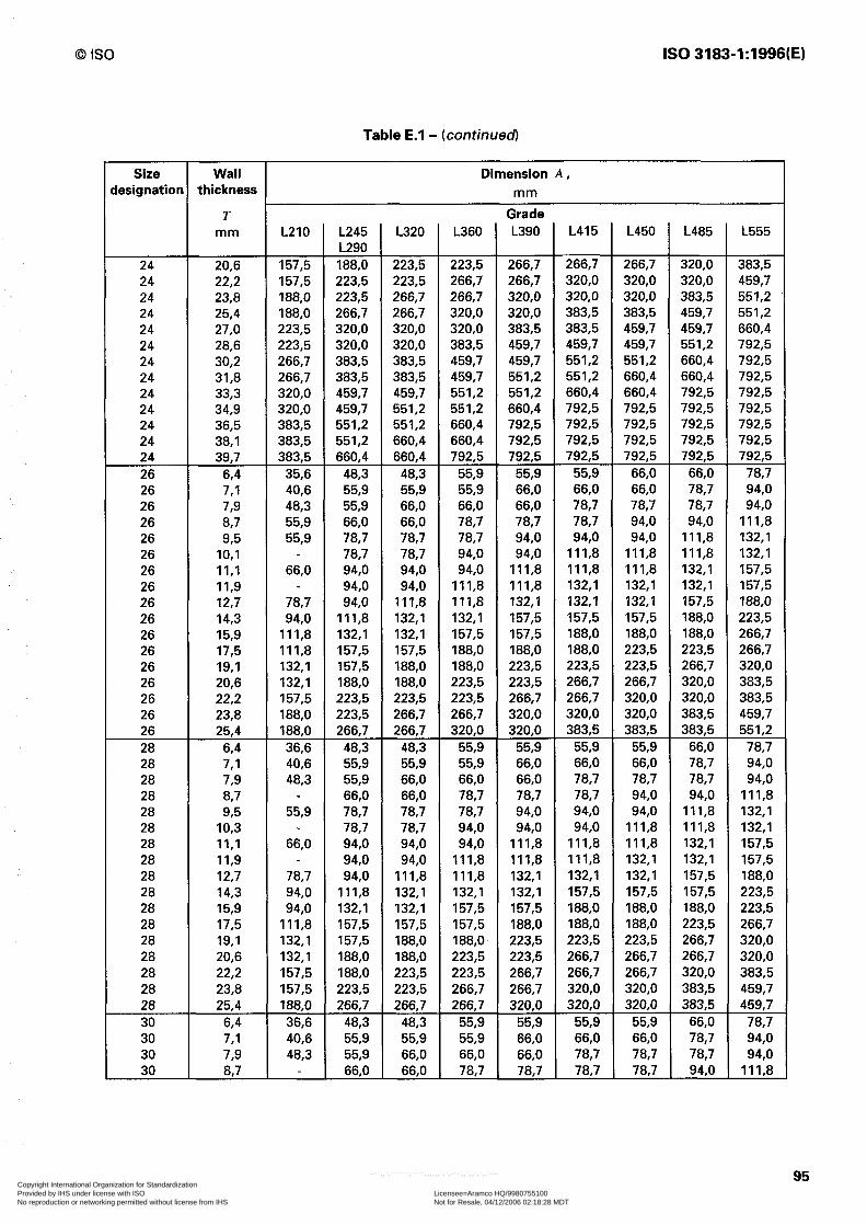
0 IS0 IS0 3183-1:1996(E)
Size lesignation
Wall thickness
T mm
24 20,6 24 22,2 24 23,8 24 25,4 24 27,0 24 28,6 24 30,2 24 31,8 24 33,3 24 34,9 24 36,5 24 38,l 24 39,7 26 6,4 26 7,l 26 73 26 8,7 26 93 26 IO,1 26 II,1 26 II,9 26 12,7 26 14,3 26 15,9 26 17,5 26 19,l 26 20,6 26 22,2 26 23,8 26 25,4 28 64 28 7,l 28 73 28 8,7 28 93 28 IO,3 28 II,1 28 II,9 28 12,7 28 14,3 28 15,9 28 17,5 28 19,l 28 20,6 28 22,2 28 23,8 28 25,4 30 684 30 7,l 30 73 30 87
Table E.l - (continued)
Dimension A, mm
L210
157,5 157,5 188,O 188,O 223,5 223,5 266,7 266,7 320,O 320,O 383,5 383,5 383,5
35,6 40,6 48,3 55,9 55,9
66,O
78,7 94,0
Ill,8 Ill,8 132,l 132,l 157,5 188,O 188,O
36,6 40,6 48,3
55,9
66,O
78,7 94,0 94,0
Ill,8 132,l 132,l 157,5 157,5 188,O
36,6 40,6 48.3
L245 L290 188,O 223,5 223,5 266,7 320,O 320,O 383,5 383,5 459,7 459,7 551,2 551,2 660,4
48,3 55,9 55,9 66,O 78,7 78,7 94,0 94,0 94,0
Ill,8 132,l 157,5 157,5 188,O 223,5 223,5 266,7
48,3 55,9 55,9 66,O 78,7 78,7 94,0 94,0 94,0
Ill,8 132,l 157,5 157,5 188,O 188,O 223,5 266,7
48,3 55,9 55,9 66,O
L320 L360 Grade L390 L415 L450 L485 L555
223,5 223,5 266,7 266,7 266,7 320,O 383,5 223,5 266,7 266,7 320,O 320,O 320,O 459,7 266,7 266,7 320,O 320,O 320,O 383,5 551,2 266,7 320,O 320,O 383,5 383,5 459,7 551,2 320,O 320,O 383,5 383,5 459,7 459,7 660,4 320,O 383,5 459,7 459,7 459,7 551,2 792,5 383,5 459,7 459,7 551,2 551,2 660,4 792,5 383,5 459,7 551,2 551,2 660,4 660,4 792,5 459,7 551,2 551,2 660,4 660,4 792,5 792,5 551,2 551,2 660,4 792,5 792,5 792,5 792,5 551,2 660,4 792,5 792,5 792,5 792,5 792,5 660,4 660,4 792,5 792,5 792,5 792,5 792,5 660,4 792,5 792,5 792,5 792,5 792,5 792,5
48,3 55,9 55,9 55,9 66,O 66,O 78,7 55,9 55,9 66,O 66,O 66,O 78,7 94,0 66,O 66,O 66,O 78,7 78,7 78,7 94,0 66,O 78,7 78,7 78,7 94,0 94,0 Ill,8 78,7 78,7 94,0 94,0 94,0 Ill,8 132,l 78,7 94,0 94,0 Ill,8 Ill,8 Ill,8 132,l 94,0 94,0 Ill,8 Ill,8 Ill,8 132,l 157,5 94,0 Ill,8 Ill,8 132,l 132,l 132,l 157,5
Ill,8 Ill,8 132,l 132,l 132,l 157,5 188,O 132,l 132,l 157,5 157,5 157,5 188,O 223,5 132,l 157,5 157,5 188,O 188,O 188,O 266,7 157,5 188,O 188,O 188,O 223,5 223,5 266,7 188,O 188,O 223,5 223,5 223,5 266,7 320,O 188,O 223,5 223,5 266.7 266,7 320,O 383,5 223,5 223,5 266,7 266,7 320,O 320,O 383,5 266,7 266,7 320,O 320,O 320,O 383,5 459,7 266,7 320,O 320,O 383,5 383,5 383,5 551,2
48,3 55,9 55,9 55,9 55,9 66,O 78,7 55,9 55,9 66,O 66,O 66,O 78,7 94,0 66,O 66,O 66,O 78,7 78,7 78,7 94,0 66,O 78,7 78,7 78,7 94,0 94,0 Ill,8 78,7 78,7 94,0 94,0 94,0 Ill,8 132,l 78,7 94,0 94,0 94,0 Ill,8 Ill,8 132,l 94,0 94,0 Ill,8 Ill,8 Ill,8 132,l 157,5 94,0 Ill,8 Ill,8 Ill,8 132,l 132,l 157,5
Ill,8 Ill,8 132,l 132,l 132,l 157,5 188,O 132,l 132,l 132,l 157,5 157,5 157,5 223,5 132,l 157,5 157,5 188,O 188,O 188,O 223,5 157,5 157,5 188,O 188,O 188,O 223,5 266,7 188,O 188,O 223,5 223,5 223,5 266,7 320,O 188,O 223,5 223,5 266,7 266,7 266,7 320,O 223,5 223,5 266,7 266,7 266,7 320,O 383,5 223,5 266,7 266,7 320,O 320,O 383,5 459,7 266,7 266,7 320,O 320,O 320,O 383,5 459,7
48,3 55,9 55,9 55,9 55,9 66,O 78,7 55,9 55,9 66,O 66,O 66,O 78,7 94,0 66,O 66,O 66,O 78,7 78,7 78,7 94,0 66,O 78,7 78,7 767 78,7 940 Ill,8
95 Copyright International Organization for Standardization Provided by IHS under license with ISO Licensee=Aramco HQ/9980755100
Not for Resale, 04/12/2006 02:18:28 MDTNo reproduction or networking permitted without license from IHS
--``,,`,```````,`````,,,,,,`,`,-`-`,,`,,`,`,,`---
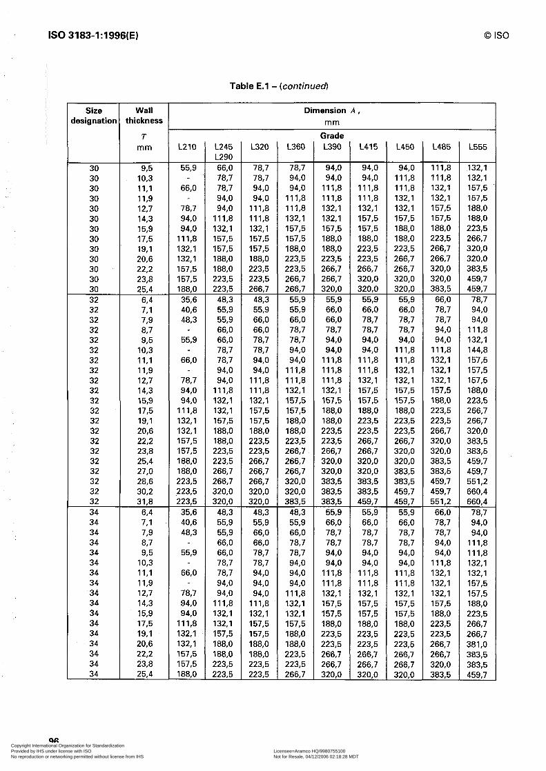
IS0 3183-1:1996(E)
96
Size lesignatior
Wall thickness
T mm
30 93 30 IO,3 30 II,1 30 II,9 30 12,7 30 14,3 30 15,9 30 17,5 30 19,l 30 20,6 30 22,2 30 23,8 30 25,4 32 6,4 32 7,l 32 73 32 8,7 32 93 32 IO,3 32 II,1 32 1 I,9 32 12,7 32 14,3 32 15,9 32 17,5 32 19,l 32 20,6 32 22,2 32 23,8 32 25,4 32 27,0 32 28,6 32 30,2 32 31,8 34 64 34 7,l 34 73 34 8,7 34 93 34 IO,3 34 II,1 34 II,9 34 12,7 34 14,3 34 15,9 34 17,5 34 19,l 34 20,6 34 22,2 34 23,8 34 25,4
F Table E.l - (continued
Dimension A, mm
L210
55,9
66,O
78,7 94,0 94,0
Ill,8 132,l 132,l 157,5 157,5 188,O
35,6 40,6 48,3
55,9
66,O
78,7 94,0 94,0
Ill,8 132,l 132,l 157,5 157,5 188,O 188,O 223,5 223,5 223,5
35,6 40,6 48,3
55,9
66,O
78,7 94,0 94,0
Ill,8 132,l 132,l 157,5 157,5 188,O
L245 L290 66,O 78,7 78,7 94,0 94,0
Ill,8 132,l 157,5 157,5 188,O 188,O 223,5 223,5
48,3 55,9 55,9 66,O 66,O 78,7 78,7 94,0 94,0
Ill,8 132,l 132,l 157,5 188,O 188,O 223,5 223,5 266,7 266,7 320,O 320,O
48,3 55,9 55,9 66,O 66,O 78,7 78,7 94,0 94,0
Ill,8 132,l 132,l 157,5 188,O 188,O 223,5 223,5
L320 L360 Grade L390 L415 L450 L485
0 IS0
I L555
78,7 78,7 94,0 94,0 94,0 Ill,8 132,l 78,7 94,0 94,0 94,0 Ill,8 Ill,8 132,l 94,0 94,0 Ill,8 Ill,8 111.8 132,l 157,5 94,0 Ill,8 Ill,8 Ill,8 132.1 132,l 157,5
Ill,8 Ill,8 132,l 132,l 132,l 157,5 188,O Ill,8 132,l 132,l 157,5 157,5 157,5 188,O 132,l 157,5 157,5 157,5 188,O 188,O 223,5 157,5 157,5 188,O 188,O 188,O 223,5 266,7 157,5 188,O 188,O 223,5 223,5 266,7 320,O 188,O 223,5 223,5 223,5 266,7 266,7 320,O 223,5 223,5 266,7 266,7 266,7 320,O 383,5 223,5 266,7 266,7 320,O 320,O 320,O 459,7 266,7 266,7 320,O 320,O 320,O 383,5 459,7
48,3 55,9 55,9 55,9 55,9 66,O 78,7 55,9 55,9 66,O 66,O 66,O 78,7 94,0 66,O 66,O 66,O 78,7 78,7 78,7 94,0 66,O 78,7 78,7 78,7 78,7 94,0 Ill,8 78.7 78,7 94,0 94,0 94,0 94,0 132,l 78,7 94,0 94,0 94,0 Ill,8 Ill,8 144,8 94,0 94,0 Ill,8 Ill,8 Ill,8 132,l 157,5 94,0 Ill,8 11 I,8 Ill,8 132,l 132,l 157,5
Ill,8 Ill,8 Ill,8 132,l 132,l 132,l 157,5 Ill,8 132,l 132,l 157,5 157,5 157,5 188,O 132,l 157,5 157,5 157,5 157,5 188,O 223,5 157,5 157,5 188,O 188,O 188,O 223,5 266,7 157,5 188,O 188,O 223,5 223,5 223,5 266,7 188,O 188,O 223,5 223,5 223,5 266,7 320,O 223,5 223,5 223,5 266,7 266,7 320,O 383,5 223,5 266,7 266,7 266,7 320,O 320.0 383,5 266,7 266,7 320,O 320,O 320,O 383,5 459,7 266,7 266,7 320,O 320,O 383,5 383,5 459,7 266,7 320,O 383,5 383,5 383,5 459,7 551,2 320,O 320,O 383,5 383,5 459,7 459,7 660,4 320,O 383,5 383,5 459,7 459,7 551,2 660,4
48,3 48,3 55,9 55,9 55,9 66,O 78,7 55,9 55,9 66,O 66,O 66,O 78,7 94,0 66,O 66,O 78,7 78,7 78,7 78,7 94,0 66,O 78,7 78,7 78,7 78,7 94,0 Ill,8 78,7 78,7 94,0 94,0 94,0 94,0 Ill,8 78,7 94,0 94,0 94,0 94,0 Ill,8 132,l 94,0 94,0 Ill,8 Ill,8 Ill,8 132,l 132,l 94,0 94,0 Ill,8 Ill,8 111.8 132,l 157,5 94,0 Ill,8 132,l 132,l 132,l 132,l 157,5
Ill,8 132,l 157,5 157,5 157,5 157,5 188,O 132,l 132,l 157,5 157,5 157,5 188,O 223,5 157,5 157,5 188,O 188,O 188,O 223,5 266,7 157,5 188,O 223,5 223,5 223,5 223,5 266,7 188,O 188,O 223,5 223,5 223,5 266,7 381,0 188,O 223,5 266,7 266,7 266,7 266,7 383,5 223,5 223,5 266,7 266,7 266,7 320,O 383,5 223,5 266,7 320,O 320,O 320.0 383,5 459.7
/
I /
1 I I
b , I ,
/
/
j
/ 1
/
i i’
f
1
I /
i
I i
F
i
,
I
/
*
i
j I,
[
i
Copyright International Organization for Standardization Provided by IHS under license with ISO Licensee=Aramco HQ/9980755100
Not for Resale, 04/12/2006 02:18:28 MDTNo reproduction or networking permitted without license from IHS
--``,,`,```````,`````,,,,,,`,`,-`-`,,`,,`,`,,`---
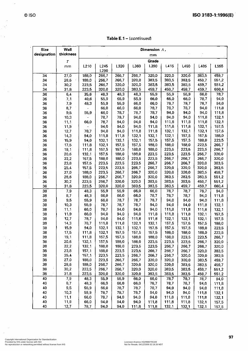
0 IS0 IS0 3183-1:1996(E)
Table E.l - (continued)
Size Wall Dimension A, iesignation thickness mm
T mm L210 L245
L290 266,7 266,7 266,7 320,O
48,3 55,9 55,9 66,O 66,O 78,7 78,7 94,0 94,0
Ill,8 132,l 132,l 157,5 157,5 188,O 223,5 223,5 223,5 266,7 266,7 320,O
55,9 66,O 66,O 78,7 78,7 94,0 94,0
Ill,8 132,l 132,l 157,5 157,5 188,O 188,O 223,5 223,5 266,7 266,7 320,O
55,9 66,O 66,O 78,7 78,7 94,0 94,o
L320 L360 Grade L390
34 27,0 34 28,6 34 30,2 34 31,8 36 64 36 7,l 36 73 36 8,7 36 93 36 IO,3 36 II,1 36 II,9 36 12,7 36 14,3 36 15,9 36 17,5 36 19,l 36 20,6 36 22,2 36 23,8 36 25,4 36 27,0 36 28,6 36 30,2 36 31,8 38 7.9 38 EL7 38 93 38 IO,3 38 II,1 38 II,9 38 12,7 38 14,3 38 15,9 38 17,5 38 19,l 38 20,6 38 22,2 38 23,8 38 25,4 38 27,0 38 28,6 38 30,2 38 31,8 40 73 40 67 40 93 40 IO,3 40 II,1 40 II,9 40 12,7
188,O 188,O 223,5 223,5
35,6 40,6 48,3
55,9
66,O
78,7 94,0 94,0
Ill,8 Ill,8 132,l 157,5 157,5 157,5 188,O 188,O 223,5 223,5
48,3 48,3 55,9 55,9 66,O 66,O 78,7 78,7 94,0
Ill,8 Ill,8 132,l 132,l 157,l 157,l 188,O 188,O 223,5 223,5
48,3 48,3 55,9 55,9 66,O 66,O 787
266,7 266,7 320,O 320,O 320,O 383,5 459,7 266,7 320,O 383,5 383,5 383,5 459,7 551,2 320,O 320,O 383,5 383,5 383,5 459,7 551,2' 320,O 383,5 459,7 459,7 459,7 459,7 660,4
48,3 48,3 55,9 55,9 55,9 66,O 78,7 55,9 55,9 66,O 66,O 66,O 78,7 94,0 55,9 66,O 66,O 78,7 78,7 78,7 94,0 66,O 66,O 78,7 78,7 78,7 94,0 Ill,8 78,7 78,7 78,7 94,0 94,0 94,0 Ill,8 78,7 94,0 94,0 94,0 94,0 Ill,8 132,l 94,0 94,0 94,0 Ill,8 Ill,8 Ill,8 132,l 94,0 94,0 Ill,8 Ill,8 Ill,8 132,l 157,5 94,0 Ill,8 Ill,8 132,l 132,l 132,l 157,5
Ill,8 132,l 132,l 132,l 157,5 157,5 188,O 132,l 132,l 157,5 157,5 157,5 188,O 223,5 157,5 157,5 188,O 188,O 188,O 223,5 266,7 157,5 188,O 188,O 223,5 223,5 223,5 266,7 188,O 188,O 223,5 223,5 223,5 266,7 320,O 188,O 223,5 223,5 266,7 266,7 266,7 320,O 223,5 223,5 266,7 266,7 266,7 320,O 383,5 223,5 266,7 266,7 320,O 320,O 320,O 383,5 266,7 266,7 320,O 320,O 320,O 383,5 459,7 266,7 320,O 320,O 383,5 283,5 383,5 551,2 320,O 320,O 383,5 383,5 383,5 459,7 551,2 320,O 383,5 383,5 383,5 459,7 459,7 660,4
55,9 66,O 66,O 78,7 78,7 78,7 94,0 66,O 66,O 78,7 78,7 78,7 94,0 Ill,8 78,7 78,7 78,7 94,0 94,0 94,0 Ill,8 78,7 78,7 94,0 94,0 94,0 Ill,8 132,l 94,0 94,0 94,0 Ill,8 Ill,8 Ill,8 132,l 94,0 94,0 Ill,8 Ill,8 Ill,8 132,l 157,5 94,0 Ill,8 Ill,8 132,l 132,l 132,l 157,5
Ill,8 132,l 132,l 157,5 157,5 157,5 188,O 132,l 132,l 157,5 157,5 157,5 188,O 223‘5 157,5 157,5 157,5 188,O 188,O 188,O 223,5 157,5 188,O 188,O 188,O 223,5 223,5 266,7 188,O 188,O 223,5 223,5 223,5 266,7 320,O 188,O 223,5 223,5 266,7 266,7 266,7 320,O 223,5 223,5 266,7 266,7 ,266,7 320,O 383,5 223,5 266,7 266,7 266,7 320,O 320,O 383,5 266,7 266,7 320,O 320,O 320,O 383,5 459,7 266,7 320,O 320,O 320,O 383,5 383,5 459,7 266,7 320,O 320,O 383,5 383,5 459,7 551,2 320,O 320,O 383,5 383,5 383,5 459,7 551,2
55,9 66,O 66,O 78,7 78,7 78,7 94,0 66,O 66,O 78,7 78,7 78,7 94,0 Ill,8 78,7 78,7 78,7 94,0 94,0 94,0 Ill,8 78,7 78,7 94,0 94,0 94,0 Ill,8 132,l 94,0 94,0 94,0 Ill,8 Ill,8 Ill,8 132,l 94,0 94,0 Ill,8 Ill,8 Ill,8 132,l 157,5 94.0 Ill,8 Ill,8 132.1 132,l 132,l 157.5
L415 L450 L485 L555
,
97 Copyright International Organization for Standardization Provided by IHS under license with ISO Licensee=Aramco HQ/9980755100
Not for Resale, 04/12/2006 02:18:28 MDTNo reproduction or networking permitted without license from IHS
--``,,`,```````,`````,,,,,,`,`,-`-`,,`,,`,`,,`---

IS0 3183-1:1996(E) 0 IS0
Table E.l - bmrinuedl
Size Wall Dimension A, designation thickness mm
T mm L210 L245
L290 Ill,8 132,l 132,l 157,5 157,5 188,O 188,O 223,5 223,5 266,7 266,7 266,7
66,O 66,O 78,7 78,7 94,0 94,0
Ill,8 132,l 132,l 157,5 157,5 188,O 188,O 223,5 223,5 266,7 266,7 266,7
66,O 66,O 78,7 78,7 94,0 94,0
Ill,8 132,l 132,l 157,5 157,5 188,O 188,O 223,5 223,5 266,7 266,7 266,7
66,O 66,O 78,7
L320 L360 Grade L390 L415
40 14,3 78,7 40 15,9 94,0 40 17,5 Ill,8 40 19,l Ill,8 40 20,6 132,l 40 22,2 132,l 40 23,8 157,5 40 25,4 157,5 40 27,0 188,O 40 28,6 188,O 40 30,2 223,5 40 31,8 223,5 42 8,7 48,3 42 93 55,9 42 IO,3 55,9 42 II,1 66,O 42 II,9 66,O 42 12,7 78,7 42 14,3 78,7 42 15,9 94,0 42 17,5 Ill,8 42 19,l Ill,8 42 20,6 132,l 42 22,2 132,l 42 23,8 157,5 42 25,4 157,5 42 27,0 188,O 42 28,6 188,O 42 30,2 188,O 42 31,8 223,5 44 8,7 48,3 44 93 55,9 44 IO,3 55,9 44 II,1 66,O 44 II,9 66,O 44 12,7 78,7 44 14,3 78,7 44 15,9 94,0 44 17,5 Ill,8 44 19,l Ill,8 44 20,6 132,l 44 22,2 132,l 44 23,8 157,5 44 25,4 157,5 44 27,0 188,O 44 28,6 188,O 44 30,2 188,O 44 31,8 223,5 46 8,7 48,3 46 985 55,9 46 IO,3 553
Ill,8 132,l 132,l 132,l 157,5 157,5 188,O 132,l 132,l 157,5 157,5 157,5 188,O 223,5 157,5 157,5 157,5 188,O 188,O 188,O 223,5 157,5 188,O 188,O 188,O 188,O 223,5 266,7 188,O 188,O 223,5 223,5 223,5 266,7 320,O 188,O 223,5 223,5 223,5 266,7 266,7 320,O 223,5 223,5 266,7 266,7 266,7 320,O 383,5 223,5 266,7 266,7 266,7 320,O 320,O 383,5 266,7 266,7 266,7 320,O 320,O 383,5 459,7 266,7 266,7 320,O 320,O 320,O 383,5 459,7 266,7 320,O 320,O 383,5 383,5 383,5 551,2 320,O 320,O 383,5 383,5 383,5 459,7 551,2
66,O 66,O 78,7 78,7 78,7 94,0 Ill,8 78,7 78,7 78,7 94,0 94,0 94,0 Ill,8 78,7 78,7 94,0 94,0 94,0 Ill,8 132,l 78,7 94,0 94,0 Ill,8 Ill,8 Ill,8 132,l 94,0 94,0 Ill,8 Ill,8 Ill,8 132,l 157,5 94,0 Ill,8 Ill,8 132,l 132,l 132,l 157,5
Ill,8 132,l 132,l 132,l 132,l 157,5 188,O 132,l 132,l 157,5 157,5 157,5 188,O 223,5 132,l 157,5 157,5 188,O 188,O 188,O 223,5 157,5 157,5 188,O 188,O 188,O 223,5 266,7 188,O 188,O 188,O 223,5 223,5 266,7 266,7 188,O 223,5 223,5 223,5 266,7 266,7 320,O 223,5 223,5 266,7 266,7 266,7 320,O 383,5 223,5 266,7 266,7 266,7 266,7 320,O 383,5 223,5 266,7 266,7 320,O 320,O 320,O 459,; 266,7 266,7 320,O 320,O 320,O 383,5 459,7 266,7 320,O 320,O 383,5 383,5 383,5 459,7 320,O 320,O 383,5 383,5 383,5 459,7 551,2
66,O 66,O 78,7 78,7 78,7 94,0 Ill,8 78,7 78,7 78,7 94,0 94,0 94,0 Ill,8 78,7 78,7 94,0 94,0 94,0 Ill,8 132,l 78,7 94,0 94,0 Ill,8 Ill,8 Ill,8 132,l 94,0 94,0 Ill,8 Ill,8 Ill,8 132,l 157,5 94,0 Ill,8 Ill,8 132,l 132,l 132,l 157,5
Ill,8 132,l 132,l 132,l 132,l 157,5 188,O 132,l 132,l 157,5 157,5 157,5 188,O 223,5 132,l 157,5 157,5 188,O 188,O 188,O 223,5 157,5 157,5 188,O 188,O 188,O 223,5 266,7 188,O 188,O 188,O 223,5 223,5 223,5 266,7 188,O 188,O 223,5 223,5 223,5 266,7 320,O 223,5 223,5 223,5 266,7 266,7 266,7 320,O 223,5 223,5 266,7 266,7 266,7 320.0 408,9 223,5 266,7 266,7 320,O 320,O 320,O 383,5 266,7 266,7 320,O 320,O 320,O 383,5 459,7 266,7 320,O 320,O 320,O 383,5 383,5 459,7 320,O 320,O 383,5 383,5 383,5 459,7 551,2
66,O 66,O 78,7 78,7 78,7 94,0 Ill,8 66,O 78,7 78,7 94,0 94,0 94,0 Ill,8 787 78,7 940 90 94,o Ill,8 132,l
L450 L485 L555
98 Copyright International Organization for Standardization Provided by IHS under license with ISO Licensee=Aramco HQ/9980755100
Not for Resale, 04/12/2006 02:18:28 MDTNo reproduction or networking permitted without license from IHS
--``,,`,```````,`````,,,,,,`,`,-`-`,,`,,`,`,,`---

0 IS0 IS0 3183-1:1996(E)
Table E.l - (continued)
Size lesignation
Wall thickness
T mm
46 II,1 46 II,9 46 12,7 46 14,3 46 15,9 46 17,5 46 19,l 46 20,6 46 22,2 46 23,8 46 25,4 46 27,0 46 28,6 46 30,2 46 31,8 48 87 48 93 48 IO,3 48 II,1 48 II,9 48 12,7 48 14,3 48 15,9 48 17,5 48 19,l 48 20,6 48 22,2 48 23,8 48 25,4 48 27,0 48 28,6 48 30,2 48 31,8 52 93 52 IO,3 52 II,1 52 II,9 52 12,7 52 14,3 52 15,9 52 17,5 52 19,l 52 20,6 52 22,2 52 23,8 52 25,4 52 27,0 52 28,6 52 30,2 52 31,8 56 9.5
L210
66,O 66,O 78,7 78,7 94,0
Ill,8 Ill,8 132,l 132,l 157,5 157,5 188,O 188,O 188,O 223,5
48,3 55,9 55,9 66,O 66,O 78,7 78,7 94,0
Ill,8 Ill,8 132,l 132,l 157,5 157,5 157,5 188,O 188,O 223,5
55,9 55,9 66,O 66,O 78,7 78,7 94,0
Ill,8 Ill,8 132,l 132.1 157,5 157,5 157,5 188,O 188,O 223,6
553
Dimension A, mm
L245 L290 78,7 94,0 94,0
Ill,8 Ill,8 132,l 157,5 157,5 188,O 188,O 223,5 223,5 223,5 266,7 266,7
66,O 66,O 78,7 78,7 94,0 94,0
Ill,8 Ill,8 132,l 157,5 157,5 188,O 188,O 223,5 223,5 223,5 266,7 266,7
66,O 78,7 78,7 94,0 94,0
Ill,8 Ill,8 132,l 157,5 157,5 188,O 188,O 188,O 223,5 223,5 266,7 266,7
66,O
L320 L360
78,7 94,0 94,0 94,0 94,0 Ill,8
Ill,8 Ill,8 132,l 132,l 132,l 157,5 157,7 157,5 157,7 188,O 188,O 188,O 188,O 223,5 223,5 223,5 223,5 266,7 266,7 266,7 266,7 320,O 320,O 320,O
66,O 66,O 66,O 78,7 78,7 78,7 78,7 94,0 94,0 94,0 94.0 Ill,8
Ill,8 Ill,8 132,l 132,l 132,l 157,5 157,5 157,5 157,5 188,O 188,O 188,O 188,O 223‘5 223,5 223,5 223,5 266,7 266,7 266,7 266,7 320,O 266,7 320,O
66,O 78,7 78,7 78,7 78,7 94,0 94,0 94,0 94,0 Ill,8
Ill,8 Ill,8 132,l 132,l 132,l 157,5 157,5 157,5 157,5 188,O 188,O 188,O 188,O 223,5 223,5 223,5 223,5 266,7 266,7 266,7 266,7 266,7 266,7 320,O
66.0 78.7
Grade L390
94.0 Ill,8 Ill,8 132,l 157,5 157,5 188,O 188,O 223,5 223,5 266,7 266,7 320,O 320.0 320,O
78,7 78,7 94,0 94,0
Ill,8 Ill,8 132,l 157,5 157,5 188,O 188,O 223,5 223‘5 266,7 266,7 320,O 320,O 320,O
78,7 94,0 94,0
Ill,8 Ill,8 132,l 157,5 157,5 188,O 188,O 223,5 223,5 266,7 266,7 266,7 320,O 320,O
78,7
L415
Ill,8 Ill,8 Ill,8 132,l 157,5 188,O 188,O 223,5 223,5 266,7 266,7 320,O 320,O 320,O 383,5
78,7 94,0 94,0
Ill,8 Ill,8 Ill,8 132,l 157,5 188,O 188,O 223,5 223,5 266.7 266,7 320,O 320,O 320,O 383,5
94,0 94,0
Ill,8 Ill,8 Ill,8 132,l 157,5 157,5 188,O 223,5 223,5 266,7 266,7 266,7 320,O 320,O 383,5
940
L450
Ill,8 Ill,8 132,l 132,l 157,5 188,O 188,O 223,5 223,5 266,7 266,7 320,O 320,O 383,5 383,5
78,7 94,0 94,0
Ill,8 Ill,8 132,l 132,l 157,5 188,O 188,O 223,5 223,5 266,7 266,7 320,O 320,O 320,O 383,5
94,0 94,0
Ill,8 Ill,8 132,l 132,l 157,5 188,O 188,O 223,5 223,5 266,7 266,7 320,O 320,O 320,O 383,5
940
L485 L555
Ill,8 132,l 132,l 157,5 132,l 157,5 _ 157,5 188,O 188,O 223,5 188,O 223,5 223,5 266,7 223,5 266,7 266,7 320,O 266,7 320,O 320,O 383,5 320,O 383,5 383,5 459,7 383,5 459,7 459,7 551,2
94,0 Ill,8 94,0 Ill,8
Ill,8 132,l Ill,8 132,l 132,l 157,5 132,l 170,2 157,5 188,O 188,O 223,5 188,O 223,5 223,5 266,7 223,5 266,7 266,7 320,O 266,7 320,O 320,O 383,5 320,O 383,5 383,5 459,7 383,5 459,7 383,5 551,2
94,0 Ill,8 Ill,8 132,l Ill,8 132,l 132,l 157,5 132,l 157,5 157,5 188,O 157,5 188,O 188,O 223,5 223,5 266,7 223,5 266,7 266,7 320,O 266,7 320,O 320,O 383,5 320,O 383,5 320,O 459,7 383,5 459,7 383,5 459,7
94,o Ill,8
99 Copyright International Organization for Standardization Provided by IHS under license with ISO Licensee=Aramco HQ/9980755100
Not for Resale, 04/12/2006 02:18:28 MDTNo reproduction or networking permitted without license from IHS
--``,,`,```````,`````,,,,,,`,`,-`-`,,`,,`,`,,`---

IS0 3183-1:1996(E) 0 IS0
Table E.l - (continued
Size lesignation
Wall thickness
T mm
56 IO,3 56 II,1 56 II,9 56 12,7 56 14,3 56 15,9 56 17,5 56 19,l 56 20,6 56 22,2 56 23,8 56 25,4 56 27,0 56 28,6 56 30,2 56 31,8 60 93 60 IO,3 60 II,1 60 II,9 60 12,7 60 14,3 60 15,9 60 17,5 60 19,l 60 20,6 60 22,2 60 23,8 60 25,4 60 27,0 60 28,6 60 30,2 60 31,8 64 93 64 IO,3 64 II,1 64 1 I,9 64 12,7 64 14,3 64 15,9 64 17,5 64 19,l 64 20,6 64 22,2 64 23,8 64 25,4 64 27,0 64 28,6 64 30,2 64 31,8 68 II,9
L210
55,9 66,O 66,O 78,7 78,7 94,0
Ill,8 Ill,8 132,l 132,l 157,5 157,5 157,5 188,O 188,O 188,O
55,9 55,9 66,O 66,O 78,7 78,7 94,0 94,0
Ill,8 132,l 132,l 132,l 157,5 157,5 188,O 188,O 188,O
55,9 55,9 66,O 66,O 78,7 78,7 94,0 94,0
Ill,8 132,l 132,l 132,l 157,5 157,5 188,O 188,O 188.0 66,O
Dimension A, mm
L245 L290 78,7 78,7 94,0 94,0
Ill,8 Ill,8 132,l 157.5 157,5 188,O 188,O 188,O 223,5 223,5 266,7 266,7
66,O 78,7 78,7 78,7 94,0
Ill,8 Ill,8 132,l 132,l 157,5 157,5 188‘0 188,O 223,5 223,5 266,7 266,7
66,O 78,7 78,7 78,7 94,0
Ill,8 Ill,8 132,l 132,l 157,5 157,5 188,O 188,O 223,5 223,5 223,5 266,7
767
L320 L360
78,7 78,7 78,7 94,0 94,0 94,0 94,0 Ill,8
Ill,8 Ill,8 132,l 132,l 132,l 157,5 157,5 157,5 157,5 188,O 188,O 188,O 188,O 223,5 223,5 223,5 223,5 266,7 223,5 266,7 266,7 266,7 266,7 320,O
66,O 78,7 78,7 78,7 78,7 94,0 94,0 94,0 94,0 Ill,8
Ill,8 Ill,8 132,l 132,l 132,l 157,5 157,5 157,5 157,5 188,O 188,O 188,O 188,O 223,5 223,5 223,5 223,5 223,5 223,5 266,7 266,7 266,7 266,7 320,O
66,O 78,7 78,7 78,7 78,7 94,0 94,0 94,0 94,0 Ill,8
Ill,8 Ill,8 132,l 132,l 132,l 157,5 157,5 157,5 157,5 188,O 188,O 188,O 188,O 223,5 223,5 223,5 223,5 223,5 223,5 266,7 266,7 266,7 266,7 266,7
94,o 940
Grade L390
94,0 94,0
Ill,8 Ill,8 132,l 132,l 157,5 188,O 188,O 223,5 223,5 266,7 266,7 266,7 320,O 320,O
78,7 94,0 94,0
Ill,8 Ill,8 132,l 132,l 157,5 188,O 188,O 223,5 223,5 223,5 266,7 266,7 320,O 320,O
78,7 94,0 94,0
Ill,8 Ill,8 132,l 132,l 157,5 188,O 188,O 223,5 223,5 223,5 266,7 266,7 320,O 320,O Ill,8
L415
94,0 94,0
Ill,8 Ill,8 132,l 157,5 157,5 188,O 188,O 223,5 223,5 266,7 266,7 320,O 320,O 320,O
78,7 94,0 94,0
Ill,8 Ill,8 132,l 157,5 157,5 188,O 188,O 223,5 223,5 266,7 266,7 320,O 320,O 320,O
78,7 94,0 94,0
Ill,8 Ill,8 132,l 157,5 157,5 188,O 188,O 223,5 223,5 266,7 266,7 266,7 320,O 320,O Ill,8
L450
94,0 Ill,8 Ill,8 Ill,8 132,l 157,5 188,O 188,O 223,5 223,5 266,7 266,7 266,7 320,O 320,O 383,5
94,0 94,0
Ill,8 Ill,8 Ill,8 132,l 157,5 157,5 188,O 223,5 223,5 266‘7 266,7 266,7 320,O 320,O 320,O
94,0 94,0
Ill,8 Ill,8 Ill,8 132,l 157,5 157,5 188,O 223,5 223,5 223,5 266,7 266,7 320,O 320,O 320,O Ill,8
L485
Ill,8 Ill,8 132,l 132,l 157,5 157,5 188,O 223,5 223,5 266,7 266,7 320,O 320,O 320,O 383,5 383,5
94,0 Ill,8 Ill,8 132,l 132,l 157,5 157,5 188,O 223,5 223,5 266,7 266,7 266,7 320,O 320,O 383,5 383,5
94,0 Ill,8 Ill,8 132,l 132,l 157,5 157,5 188,O 188,O 223,5 266,7 266,7 266,7 320,O 320,O 383,5 383,5 Ill,8
L555
132,l 132,l 157,5 157,5 188,O 188,O 223,5 266,7 266,7 320,O 320,O 383,5 383,5 383,5 459,7 459,7 Ill,8 132,l 132,l 132,l 157,5 188,O 188,O 223,5 223,5 266,7 266,7 320,O 320,O 383,5 383,5 459,7 459,7 Ill,8 132,l 132,l 132,l 157,5 188,O 188,O 223,5 223,5 266,7 266,7 320,O 320,O 383,5 383,5 459,7 459,7 132,l
100Copyright International Organization for Standardization Provided by IHS under license with ISO Licensee=Aramco HQ/9980755100
Not for Resale, 04/12/2006 02:18:28 MDTNo reproduction or networking permitted without license from IHS
--``,,`,```````,`````,,,,,,`,`,-`-`,,`,,`,`,,`---
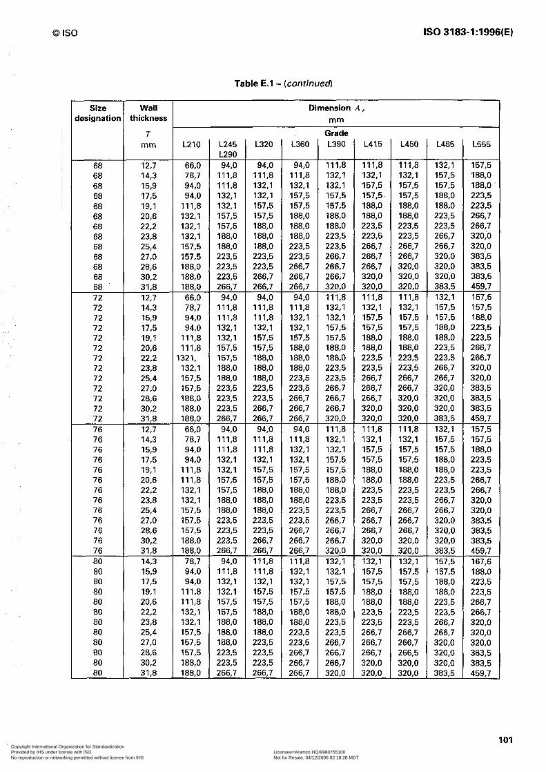
0 IS0 IS0 3183-1:1996(E)
Table E.l - (continued
Size designation
Wall thickness
T mm L210
68 12,7 66,O 68 14,3 78,7 68 15,9 94,0 68 17,5 94,0 68 19,l Ill,8 68 20,6 132,l 68 22,2 132,l 68 23,8 132,l 68 25,4 157,5 68 27,0 157,5 68 28,6 188,O 68 30,2 188,O 68 31,8 188,O 72 12,7 66,O 72 14,3 78,7 72 15,9 94,0 72 17,5 94,0 72 19,l Ill,8 72 20,6 Ill,8 72 22,2 1321, 72 23,8 132,l 72 25,4 157,5 72 27,0 157,5 72 28,6 188,O 72 30,2 188,O 72 31,8 188,O 76 12,7 66,O 76 14,3 78.7 76 15,9 94,0 76 17,5 94,0 76 19,l Ill,8 76 20,6 Ill,8 76 22,2 132,l 76 23,8 132,l 76 25,4 157,5 76 27,0 157,5 76 28,6 157,5 76 30,2 188,O 76 31,8 188,O 80 14,3 78,7 80 15,9 94,0 80 17,5 94,0 80 19,l Ill,8 80 20,6 Ill,8 80 22,2 132,l 80 23,8 132,l 80 25,4 157,5 80 27,0 157,5 80 28,6 157,5 80 30,2 188,O 80 31,8 188,O
Dimension A, mm
L245 L290 94,0
Ill,8 Ill,8 132,l 132,l 157,5 157,5 188,O 188,O 223,5 223,5 223,5 266,7
94,0 Ill,8 111.8 132,l 132,l 157,5 157,5 188,O 188,O 223,5 223,5 223,5 266,7
94,0 Ill,8 Ill,8 132,l 132,l 157,5 157,5 188,O 188,O 223,5 223,5 223,5 266,7
94,0 Ill,8 132,l 132,l 157,5 157,5 188,O 188,O 188,O 223,5 223,5 266,7
L320
94,0 Ill,8 132,l 132,l 157,5 157,5 188,O 188,O 188,O 223,5 223,5 266,7 266,7
94,0 Ill,8 Ill,8 132,l 157,5 157,5 188,O 188,O 188,O 223,5 223,5 266,7 266,7
94,0 Ill,8 Ill,8 132,l 157,5 157,5 188,O 188,O 188,O 223,5 223,5 266,7 266,7 Ill,8 Ill,8 132,l 157,5 157,5 188,O 188,O 188,O 223,5 223,5 223,5 266,7
L360
94,0 Ill,8 132‘1 157,5 157,5 188,O 188,O 188,O 223,5 223,5 266,7 266,7 266,7
94,0 Ill,8 132,l 132,l 157,5 188,O 188,O 188,O 223,5 223,5 266,7 266,7 266,7
94,0 Ill,8 132,l 132,l 157,5 157,5 188,O 188,O 223,5 223,5 266,7 266,7 266,7 Ill,8 132,l 132,l 157,5 157,5 188,O 188,O 223,5 223,5 266,7 266,7 266,7
Grade L390
Ill,8 132,l 132,l 157,5 157,5 188,O 188,O 223,5 223,5 266,7 266,7 266,7 320,O Ill,8 132,l 132,l 157,5 157,5 188,O 188,O 223,5 223,5 266,7 266,7 266,7 320,O Ill,8 132,l 132,l 157,5 157,5 188,O 188,O 223,5 223,5 266,7 266,7 266,7 320,O 132,l 132,l 157,5 157,5 188,O 188,O 223,5 223,5 266,7 266,7 266,7 320,O
L415
Ill,8 132,l 157,5 157,5 188,O 188,O 223,5 223,5 266,7 266,7 266,7 320,O 320,O Ill,8 132,l 157,5 157,5 188,O 188,O 223,5 223,5 266,7 266,7 266,7 320,O 320,O Ill,8 132,l 157,5 157,5 188,O 188,O 223,5 223,5 266,7 266,7 266,7 320,O 320,O 132,l 157,5 157,5 188,O 188,O 223,5 223,5 266,7 266,7 266,7 320,O 320,O
L450
Ill,8 132,l 157,5 157,5 188,O 188,O 223,5 223,5 266,7 266,7 320,O 320,O 320,O Ill,8 132,l 157,5 157,5 188,O 188,O 223,5 223,5 266,7 266,7 320,O 320,O 320,O Ill,8 132,l 157,5 157,5 188,O 188,O 223,5 223,5 266,7 266,7 266,7 320,O 320,O 132,l 157,5 157,5 188,O 188,O 223,5 223,5 266,7 266,7 266,5 320,O 320,O
L485
132,l 157,5 157,5 188,O 157,5 188,O' 188,O 223,5 188,O 223,5 223,5 266,7 223,5 266,7 266,7 320,O 266,7 320,O 320,O 383,5 320,O 383,5 320,O 383,5 383,5 459,7 132,l 157,5 157,5 157,5 157,5 188,O 188,O 223,5 188,O 223,5 223,5 266,7 223,5 266,7 266,7 320,O 266,7 320,O 320,O 383,5 320,O 383,5 320,O 383,5 383,5 459,7 132,l 157,5 157,5 157,5 157,5 188,O 188,O 223,5 188,O 223,5 223,5 266,7 223,5 266,7 266,7 320,O 266,7 320,O 320,O 383,5 320,O 383,5 320,O 383,5 383,5 459,7 157,5 167,6 157,5 188,O 188,O 223,5 188,O 223,5 223,5 266,7 223,5 266,7 266,7 320,O 266,7 320,O 320,O 320,O 320,O 383,5 320,O 383,5 383,5 459,7
L555
101 Copyright International Organization for Standardization Provided by IHS under license with ISO Licensee=Aramco HQ/9980755100
Not for Resale, 04/12/2006 02:18:28 MDTNo reproduction or networking permitted without license from IHS
--``,,`,```````,`````,,,,,,`,`,-`-`,,`,,`,`,,`---

IS0 3183-1:1996(E)
Annex F (normative)
0 IS0
Purchaser inspection
F.l Inspection notice
Where the inspector representing the purchaser desires to inspect pipes or witness particular tests, reasonable notice shall be given of the time at which the run is to be made.
F.2 Plant access
The inspector representing the purchaser, shall have unrestricted access at all times while work on the contract of the purchaser is being performed, to all parts of the manufacturer’s works which concern the manufacture of the pipe ordered. The manufacturer shall afford the inspector all reasonable facilities to satisfy himself that the pipe is being manufactured in accordance with this specification. All inspections should be made at the place of manufacture prior to shipment, unless otherwise specified on the purchase order, and shall be so conducted as not to interfere unnecessarily with the operation of the works.
F.3 Compliance
The manufacturer is responsible for complying with all of the provisions of this specification. The purchaser may make any investigation necessary to satisfy himself of compliance by the manufacturer and may reject any material that does not comply with this specification.
F.4 Rejection
Unless otherwise provided, material which shows defects on inspection subsequent to acceptance at the manufacturer’s works, or which proves defective when properly applied in service, may be rejected, and the manufacturer so notified. If tests that require the destruction of material are made, any product which is proven to have not met the requirements of the specification shall be rejected. Disposition of rejected product shall be a matter of agreement between the manufacturer and the purchaser.
102 Copyright International Organization for Standardization Provided by IHS under license with ISO Licensee=Aramco HQ/9980755100
Not for Resale, 04/12/2006 02:18:28 MDTNo reproduction or networking permitted without license from IHS
--``,,`,```````,`````,,,,,,`,`,-`-`,,`,,`,`,,`---
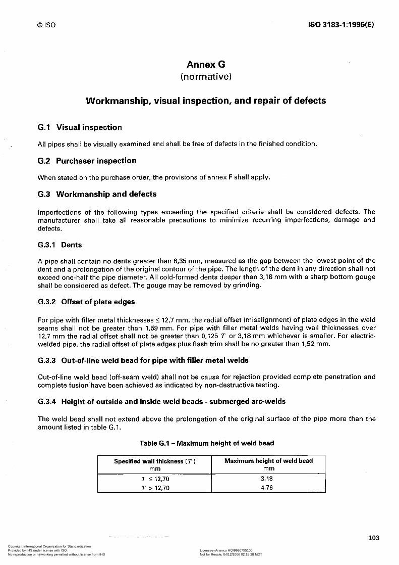
0 IS0 IS0 3183-1:1996(E)
Annex G (normative)
Workmanship, visual inspection, and repair of defects
G.l Visual inspection
All pipes shall be visually examined and shall be free of defects in the finished condition.
G.2 Purchaser inspection
When stated on the purchase order, the provisions of annex F shall apply.
G.3 Workmanship and defects
Imperfections of the following types exceeding the specified criteria shall be considered defects. The manufacturer shall take all reasonable precautions to minimize recurring imperfections, damage and defects.
G.3.1 Dents
A pipe shall contain no dents greater than 6,35 mm, measured as the gap between the lowest point of the dent and a prolongation of the original contour of the pipe. The length of the dent in any direction shall not exceed one-half the pipe diameter. All cold-formed dents deeper than 3,18 mm with a sharp bottom gouge shall be considered as defect. The gouge may be removed by grinding.
G.3.2 Offset of plate edges
For pipe with filler metal thicknesses I 12,7 mm, the radial offset (misalignment) of plate edges in the weld seams shall not be greater than I,59 mm. For pipe with filler metal welds having wall thicknesses over 12,7 mm the radial offset shall not be greater than 0,125 T or 3,18 mm whichever is smaller. For electric- welded pipe, the radial offset of plate edges plus flash trim shall be no greater than I,52 mm.
G.3.3 Out-of-line weld bead for pipe with filler metal welds
Out-of-line weld bead (off-seam weld) shall not be cause for rejection provided complete penetration and complete fusion have been achieved as indicated by non-destructive testing.
G.3.4 Height of outside and inside weld beads - submerged arc-welds
The weld bead shall not extend above the prolongation of the original surface of the pipe more than the amount listed in table G.I.
Table G.l - Maximum height of weld bead
Specified wall thickness ( T ) Maximum height of weld bead mm mm
T I12,70 3,18 T > 12.70 4,76
103Copyright International Organization for Standardization Provided by IHS under license with ISO Licensee=Aramco HQ/9980755100
Not for Resale, 04/12/2006 02:18:28 MDTNo reproduction or networking permitted without license from IHS
--``,,`,```````,`````,,,,,,`,`,-`-`,,`,,`,`,,`---
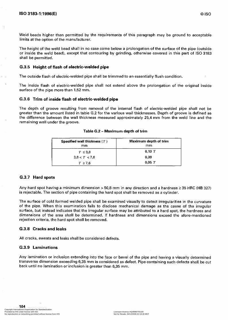
IS0 3183-1:1996(E) 0 IS0
Weld beads higher than permitted by the requirements of this paragraph may be ground to acceptable limits at the option of the manufacturer.
The height of the weld bead shall in no case come below a prolongation of the surface of the pipe (outside or inside the weld bead), except that contouring by grinding, otherwise covered in this part of IS0 3183 shall be permitted.
G.3.5 Height of flash of electric-welded pipe
The outside flash of electric-welded pipe shall be trimmed to an essentially flush condition.
The inside flash of electric-welded pipe shall not extend above the prolongation of the original inside surface of the pipe more than I,52 mm.
G-3.6 Trim of inside flash of electric-welded pipe
The depth of groove resulting from removal of the internal flash of electric-welded pipe shall not be greater than the amount listed in table G.2 for the various wall thicknesses. Depth of groove is defined as the difference between the wall thickness measured approximately 25,4 mm from the weld line and the remaining wall under the groove.
Table G.2 - Maximum depth of trim
Specified wall thickness ( T ) Maximum depth of trim mm mm
T 23‘8 0,lO T
3,8 c T c 7,6 0,38
T 2 7,6 0,05 T
6.3.7 Hard spots
Any hard spot having a minimum dimension > 50,8 mm in any direction and a hardness 2 35 HRC (HB 327) is rejectable. The section of pipe containing the hard spot shall be removed as a cylinder.
The surface of cold formed welded pipe shall be examined visually to detect irregularities in the curvature of the pipe. When this examination fails to disclose mechanical damage as the cause of the irregular surface, but instead indicates that the irregular surface may be attributed to a hard spot, the hardness and dimensions of the area shall be determined. If hardness and dimensions exceed the afore-mentioned rejection criteria, the hard spot shall be removed.
G.3.8 Cracks and leaks
All cracks, sweats and leaks shall be considered defects.
G.3.9 Laminations
Any lamination or inclusion extending into the face or bevel of the pipe and having a visually determined transverse dimension exceeding 6,35 mm is considered as defect. Pipe containing such defects shall be cut back until no lamination or inclusion is greater than 6,35 mm.
104
I
j I I t I 1 I’ I i
I / I j. i: $ t i 1: i 1
!/ t /
I_ I’ /I
1;
Copyright International Organization for Standardization Provided by IHS under license with ISO Licensee=Aramco HQ/9980755100
Not for Resale, 04/12/2006 02:18:28 MDTNo reproduction or networking permitted without license from IHS
--``,,`,```````,`````,,,,,,`,`,-`-`,,`,,`,`,,`---
0 IS0 IS0 3183-1:1996(E)
Any lamination in the body of the pipe that is both:
1) 2 19,l mm in the minor dimension and
2) 2 7 742 mm* in area is considered a defect.
Disposition of such defects shall be in accordance with G.4.3 or G.4.4. No specific inspection by the manufacturer is required unless the purchaser specifies special non-destructive testing on the purchase order.
NOTE 28 A lamination is defined as an internal metal separation creating layers generally parallel to the surface.
G.3.10 Arc burns
Arc burns, defined as localized points of surface melting caused by arcing between electrode or ground and pipe surface, shall be considered defects.
NOTE 29 Contact marks, defined as intermittent marks adjacent to the weld line, resulting from the electrical contact between the electrodes supplying the welding current and the pipe surface, are not defects.
Disposition of pipe containing arc burns shall be in accordance with G.4 except that removal of defects by grinding shall be subject to the following additional conditions.
Arc burns may be removed by grinding, chipping or machining. The resulting cavity shall be thoroughly cleaned and checked for complete removal of damaged material by etching with a 10 % solution of ammonium persulfate or with a 5 % solution of nital. If removal of damaged material is complete the cavity may be merged smoothly into the original contour of the pipe by grinding, provided the remaining wall thickness is within specified limits.
G.3.11 Undercuts
Undercutting of submerged arc- or gas metal arc-welded pipe is the reduction in thickness of the pipe wall adjacent to the weld where it is fused to the surface of the pipe. Undercutting can best be located and measured visually.
Minor undercutting on either the inside or the outside of the pipe is defined in G.3.11.1 and G.3.11.2 below and is acceptable without repair or grinding.
G.3.11.1 Maximum depth of 0,79 mm and not exceeding 12,5 % of the wall thickness with a maximum length of one half the wall thickness and not more than two such undercuts in any 0,30 m of the weld length.
G.3.11.2 Maximum depth of 0,40 mm, any length.
G.3.11.3 Undercutting in excess of the above limit, shall be considered a defect. Disposition shall be as follows:
a) Undercut defects not exceeding 0,79 mm in depth and not exceeding 12,5 % of the specified wall thickness shall be removed by grinding in accordance with G.4 a).
b) Disposition of undercuts greater in depth than 0,79 mm or 12,5 % of the specified wall thickness shall be in accordance with G.4 b), c) or d).
G.3.12 Other defects
Any imperfection having a depth greater than 12,5 % of the specified wall thickness, measured from the surface of the pipe, shall be considered a defect.
105
,
Copyright International Organization for Standardization Provided by IHS under license with ISO Licensee=Aramco HQ/9980755100
Not for Resale, 04/12/2006 02:18:28 MDTNo reproduction or networking permitted without license from IHS
--``,,`,```````,`````,,,,,,`,`,-`-`,,`,,`,`,,`---

IS0 3183-1:1996(E) 0 IS0
G.4 Disposition of defects
Pipe containing a defect must be given one of the following dispositions.
a) The defect shall be removed by grinding provided the remaining wall thickness is within specified limits. Grinding shall be done in a workmanlike manner.
b) The defect shall be repaired by welding in accordance with G.5 through G.8.
c) The section of pipe containing the defect shall be cut off within the limits of requirements on length.
d) The entire pipe shall be rejected.
G.5 Repair of defects by welding
a) Seamless pipe and parent metal of welded pipes
The repair of defects in seamless pipe and parent metal of welded pipe is permissible except when the depth of defect exceeds 33% % of the specified wall thickness of the pipe and the length of that portion of the defect in which the depth exceeds 12,5 % is greater than 25 % of the specified outside diameter of the pipe, or when more than one repair is required in any length equivalent to 10 times the specified outside diameter of the pipe. Repairs shall be made in accordance with G.6. Repair welds shall be inspected by the magnetic particle method in accordance with 8.10.11.4 or by liquid penetrant or, by agreement between purchaser and manufacturer, other NDT methods may be used.
b) Weld seam of welded pipes
Defects in filler metal welds may be repaired at the discretion of the manufacturer. Such repairs shall be in accordance with G.7. Electric-welds may be repaired only by agreement between the purchaser and the manufacturer; such repairs shall be in accordance with G.8. Repair welds shall be inspected by ultrasonic methods in accordance with 8.10.11.3.1 to 8.10.11.3.3 except that the equipment need not be capable of continuous and uninterrupted operation and, at the option of the manufacturer, repairs made by submerged arc-welding or by shielded metal arc-welding may alternatively be inspected by radiological methods in accordance with 8.10.11.2.1 to 8.10.11.2.9.
c) Heat treated pipes
When heat treated pipes have been repaired by welding, the need for, and type of, reheat treatment shall be by agreement between the purchaser and the manufacturer, based on the effect of the repair on the structure and properties of the heat treated pipes.
G.6 Procedure for repair by welding of seamless pipe and parent metal of welded pipe
The repair of defects in seamless pipe and parent metal of welded pipe shall conform to the following requirements. Conformity to the repair procedure is subject to approval of the purchaser’s inspector.
a) The defect shall be removed completely by chipping and/or grinding and the resultant cavity shall be thoroughly cleaned and, before welding, shall be inspected by magnetic particle methods to ensure complete removal of the defect.
b) The minimum length of repair weld shall be 50,8 mm. Where the orientation of the defect permits, the repair weld shall be placed in the circumferential direction.
c) The repair weld shall be made either by automatic submerged arc-welding, gas metal arc-welding, or manual shielded metal arc-welding using low hydrogen electrodes. The metal temperature in the area to be repaired shall be a minimum of 10 “C. The welding procedure and performance shall be qualified in accordance with annex B.
d) The repair weld shall be ground to merge smoothly into the original contour of the pipe.
e) Repaired pipe shall be hydrostatically tested after repairing in accordance with 8.10.9.
106 Copyright International Organization for Standardization Provided by IHS under license with ISO Licensee=Aramco HQ/9980755100
Not for Resale, 04/12/2006 02:18:28 MDTNo reproduction or networking permitted without license from IHS
--``,,`,```````,`````,,,,,,`,`,-`-`,,`,,`,`,,`---

0 IS0 IS0 3183-1:1996(E)
G.7 Procedure for repair of submerged arc- and gas metal arc-welds
The repair of submerged arc- and gas metal arc-welds shall conform to the following requirements. Conformance is subject to approval of purchaser’s inspector.
a) The defect shall be completely removed and the cavity thoroughly cleaned. Where multiple pass repairs are used, the size of the cavity shall be sufficiently large (at least 50,8 mm in length) to avoid coincidence of starts and stops of individual passes.
b) The minimum length of each repair weld shall be 50,8 mm. The repair weld shall be made either by automatic submerged arc-welding, or manual shielded metal arc-welding using low hydrogen electrodes, and the welding procedure and performance shall be qualified in accordance with annex B.
c) Each length of repaired pipe shall be tested hydrostatically in accordance with 8.10.9.
G.8 Procedure for repair of electric welds
The repair of electric-welds shall conform to the following requirements and shall include the weld zone which is defined for the purposes of repair as 12,7 mm on either side of the fusion line. Conformity to the repair procedure is subject to approval of the purchaser’s inspector.
a) The weld zone defect shall be removed completely by chipping and/or grinding and the resultant cavity shall be thoroughly cleaned.
b) The minimum length of repair weld shall be 50,8 mm and individual weld repairs shall be separated by at least 3 m.
c) The repair weld shall be made either by automatic submerged arc-welding, gas metal arc-welding, or manual shielded metal arc-welding using low hydrogen electrodes. The metal temperature in the area to be repaired shall be a minimum of 10 “C. The welding procedure and performance shall be qualified in accordance with annex B.
d) When a repair weld is made through the full wall thickness, it shall include weld passes made from both the inside diameter and the outside diameter of the pipe. Starts and stops of the inside diameter and outside diameter repair welds shall not coincide.
e) The repair shall be ground to merge smoothly into the original contour of the pipe and shall have a maximum crown of I,52 mm.
f) Repaired pipe shall be hydrostatically tested after repair in accordance with 8.10.9.
107 Copyright International Organization for Standardization Provided by IHS under license with ISO Licensee=Aramco HQ/9980755100
Not for Resale, 04/12/2006 02:18:28 MDTNo reproduction or networking permitted without license from IHS
--``,,`,```````,`````,,,,,,`,`,-`-`,,`,,`,`,,`---

IS0 3183-1:1996(E) 0 IS0
Annex H (informative)
Comparison of steel grade designations
This table gives a comparison of steel grade designations defined by this part of IS0 3183 against those specified in ANSI/API Spec. 5 L Ill.
Steel grade (according to IS0 3183-1)
L175 (Cl I, Cl II) L210 L245 L290 L320 L360 L390 L415 L450 L485 L555
Steel grade (according to ANSI/API Spec. 5 L)
A 25 (Cl I; Cl II) A B
X 42 X 46 X 52 X 56 X 60 X 65 x 70 X 80
108 Copyright International Organization for Standardization Provided by IHS under license with ISO Licensee=Aramco HQ/9980755100
Not for Resale, 04/12/2006 02:18:28 MDTNo reproduction or networking permitted without license from IHS
--``,,`,```````,`````,,,,,,`,`,-`-`,,`,,`,`,,`---

0 IS0 IS0 3183-1:1996(E)
Annex J (informative)
Main differences between IS0 3183-1 and ANSI/API Spec. 5L [I]
The main differences are as follows:
To SECTION 1 of ANSI/API Spec. 5L
Scope
- TFL-pipe, supplementary requirement SR7, was deleted.
- In 1.1 “Coverage” the seventh paragraph relating to field welding was deleted. The ninth paragraph relating to Class I and Class II steels is mentioned in 7.2.1 (note 4) of IS0 3183-1.
- Only metric units are used (1.2 “Metric units and conversions” was deleted).
- 1.3 “Referenced standards” was modified (see clause 2 “Normative references”).
- 1.6 “Special processes” was deleted.
- 1.7 “Certification” was completed by an alternative (IS0 10474; see clause 8.1).
To SECTION 2 of ANSI/API Spec. 5L
Process of manufacture and material
This section was separated in “definitions” (see 3.2) and in “manufacturing” (see clause 6).
The last sentence of 2.4 was inserted as separate sub-clause 6.6 “Traceability”.
To SECTION 4 of ANSI/API Spec. 5L
Mechanical properties and tests
The strength values of ANSI/API 5L were rounded to the next (higher) 5 or 10 N/mm*.
Grade designations are analogous to IS0 3183-2.
The elongation values are based on the proportional gauge length (L,, = 5,656). Therefore only one value per steel grade is fixed. These values were determined by using the API formula, converting the calculated values in accordance with IS0 2566-l and rounding non-integer values to the next higher integer. Therefore the “Elongation table” in Annex C was deleted.
Fig. 4.2 “Tensile Test Specimens” was deleted; IS0 3183-1 refers in 8.10.2 to IS0 6892 and ASTM A 370 where those specimens are given.
Fig. 4.3 “Flattening Test” was supplemented by 8.5.1.2 in IS0 3183-1 for clarification.
In this part of IS0 3183 all requirements concerning inspection and testing are contained in clause 8.
109 Copyright International Organization for Standardization Provided by IHS under license with ISO Licensee=Aramco HQ/9980755100
Not for Resale, 04/12/2006 02:18:28 MDTNo reproduction or networking permitted without license from IHS
--``,,`,```````,`````,,,,,,`,`,-`-`,,`,,`,`,,`---
IS0 3183-1:1996(E) 0 IS0
To SECTION 5 of ANSI/API Spec. 5L
All hydrostatic test pressures of tables 6.1, 6.la and 6.2 (see tables 6, 7, 8 and 9) were newly computed considering the specified minimum yield strength values (see table 3).
To SECTION 6 of ANSI/API Spec. 5L
Dimensions, masses and lengths
- The formula for mass-calculation was completed by two further digits (0,02466l5) in 7.6.1 in accordance with IS0 4200).
- Symbols for pipe mass per unit length were modified in 7.6.4.
To SECTION 9 of ANSI/API Spec. 5L
Non-destructive inspection
9.5 “Radiological NDT reference standards” supplemented by reference to IS0 1027 (see 8.10.11.2.4).
To SECTION 11 of ANSI/API Spec. 5L
Marking and coating
The symbols to be used for the manufacturing process and heat treatment were partly modified (see clause 9).
To Appendix H of ANSI/API Spec. 5L
Marking instructions for ANSI/API licensees
This annex was deleted, because it is not relevant to this International Standard.
j
I
/
,
I
[
1
L I
/
i
[
1
i
,
i /
8
t 1.
Ir
‘i ”
i
I
r v
I
i ti
I
I
I
i,
i L
i
I
110 Copyright International Organization for Standardization Provided by IHS under license with ISO Licensee=Aramco HQ/9980755100
Not for Resale, 04/12/2006 02:18:28 MDTNo reproduction or networking permitted without license from IHS
--``,,`,```````,`````,,,,,,`,`,-`-`,,`,,`,`,,`---
0 IS0 ISO3183-1:1996(E)
Annex K (informative
Bibliography r’
[II American National Standard ANSI/API Spec. 5L-1993: Specification for line pipe; 40th edition, November 1,1992.
111 Copyright International Organization for Standardization Provided by IHS under license with ISO Licensee=Aramco HQ/9980755100
Not for Resale, 04/12/2006 02:18:28 MDTNo reproduction or networking permitted without license from IHS
--``,,`,```````,`````,,,,,,`,`,-`-`,,`,,`,`,,`---

IS0 3183-1:1996(E)
ICS 75.200; 77.140.75 Descriptors: petroleum industry, piping, fluid pipelines, oil pipelines, gas pipelines, pipes (tubes), steel tubes, specifications, materials specifications, manufacturing requirements, mechanical properties, dimensions, chemical composition, tests, mechanical tests, hydrostatic tests, chemical analysis, inspection, marking, designation, delivery condition. Price based on 111 pages
Copyright International Organization for Standardization Provided by IHS under license with ISO Licensee=Aramco HQ/9980755100
Not for Resale, 04/12/2006 02:18:28 MDTNo reproduction or networking permitted without license from IHS
--``,,`,```````,`````,,,,,,`,`,-`-`,,`,,`,`,,`---