5244703 cisco switching black book
TRANSCRIPT


Table of ContentsCisco Switching Black Book...............................................................................................................................1
Introduction.........................................................................................................................................................4Overview..................................................................................................................................................4Is This Book for You?..............................................................................................................................4How to Use This Book.............................................................................................................................4The Black Book Philosophy....................................................................................................................5
Chapter 1: Network Switching Fundamentals.................................................................................................6In Depth...................................................................................................................................................6Physical Media and Switching Types......................................................................................................6A Bit of History.......................................................................................................................................7
Networking Architectures.................................................................................................................7The Pieces of Technology........................................................................................................................9
Repeaters.........................................................................................................................................10Hubs.................................................................................................................................................10Bridges.............................................................................................................................................11Routers.............................................................................................................................................13Switches...........................................................................................................................................13
Network Design.....................................................................................................................................14Collision Domains...........................................................................................................................15Broadcast Domains..........................................................................................................................16Why Upgrade to Switches?.............................................................................................................16Switched Forwarding......................................................................................................................19Switched Network Bottlenecks.......................................................................................................20The Rule of the Network Road........................................................................................................22
Switched Ethernet Innovations..............................................................................................................23Full−Duplex Ethernet......................................................................................................................23Fast Ethernet....................................................................................................................................23Gigabit Ethernet..............................................................................................................................24
The Cisco IOS........................................................................................................................................24Connecting to the Switch................................................................................................................25Powering Up the Switch..................................................................................................................25
The Challenges.......................................................................................................................................27Today’s Trend........................................................................................................................................27Entering and Exiting Privileged EXEC Mode.......................................................................................28Entering and Exiting Global Configuration Mode.................................................................................28Entering and Exiting Interface Configuration Mode.............................................................................28Entering and Exiting Subinterface Configuration Mode.......................................................................28Saving Configuration Changes..............................................................................................................29
Chapter 2: Basic Switch Configuration..........................................................................................................30In Depth.................................................................................................................................................30Command−Line Interfaces....................................................................................................................30Campus Hierarchical Switching Model.................................................................................................31
Access Layer...................................................................................................................................32Distribution Layer...........................................................................................................................32Core Layer.......................................................................................................................................33
Remote Network Monitoring.................................................................................................................33Connecting to the Console Port.............................................................................................................34
Console Cable Pinouts.....................................................................................................................35Console Connectors.........................................................................................................................36
i

Table of ContentsChapter 2: Basic Switch Configuration
The RJ−45−to−AUX Port Console Connector Pinouts...................................................................36Switch IOSs...........................................................................................................................................38
The IOS Configuration Modes........................................................................................................38Limiting Telnet Access..........................................................................................................................39Implementing Privilege Levels..............................................................................................................39Configuring an IOS−Based CLI Switch................................................................................................39
Setting the Login Passwords...........................................................................................................40Setting Privilege Levels...................................................................................................................40Assigning Allowable Commands....................................................................................................40Setting the Console Port Time−out Value.......................................................................................40Configuring the Telnet Time−out Value.........................................................................................41Configuring the Hostname..............................................................................................................41Configuring the Date and Time.......................................................................................................41Configuring an IP Address and Netmask........................................................................................41Configuring a Default Route and Gateway.....................................................................................41Configuring Port Speed and Duplex...............................................................................................42Enabling SNMP Contact.................................................................................................................42
Configuring a Set/Clear−Based CLI Switch..........................................................................................42Logging On to a Switch...................................................................................................................42Setting the Login and Enable Passwords........................................................................................43Changing the Console Prompt.........................................................................................................43Entering a Contact Name and Location Information......................................................................44Configuring System and Time Information....................................................................................44Configuring an IP Address and Netmask........................................................................................44Configuring a Default Route and Gateway.....................................................................................45Viewing the Default Routes............................................................................................................45Configuring Port Speed and Duplex...............................................................................................45Enabling SNMP...............................................................................................................................46Configuring Trap Message Targets.................................................................................................46
Configuring a Menu−Driven IOS..........................................................................................................47Configuring the Console Port..........................................................................................................48Configuring Telnet..........................................................................................................................48Configuring the Password...............................................................................................................48Configuring an IP Address and Default Gateway...........................................................................48Configuring SNMP..........................................................................................................................49
Configuring ROM..................................................................................................................................50Entering ROM Configuration Mode...............................................................................................50Booting ROM Mode from a Flash Device......................................................................................50Configuring SNMP..........................................................................................................................51Configuring RMON........................................................................................................................51Configuring RMON on a Set/Clear−Based Interface.....................................................................51
Using Set/Clear Command Set Recall Key Sequences..........................................................................52Using IOS−Based Command Editing Keys and Functions...................................................................52
Chapter 3: WAN Switching.............................................................................................................................54In Depth.................................................................................................................................................54WAN Transmission Media....................................................................................................................55
Synchronous Transport Signal (STS)..............................................................................................56Cisco WAN Switches............................................................................................................................57
MGX 8200 Series............................................................................................................................57IGX 8400 Series..............................................................................................................................58
ii

Table of ContentsChapter 3: WAN Switching
BPX 8600 Series Wide−Area Switches..........................................................................................58MGX 8800 Series Wide−Area Edge Switches...............................................................................59
WAN Switch Hardware Overview........................................................................................................59Cisco WAN Switch Network Topologies..............................................................................................60Network Management............................................................................................................................61
The CLI...........................................................................................................................................61WAN Manager................................................................................................................................61
Accessing and Setting Up IGX and BPX Switches...............................................................................62Adding New Users..........................................................................................................................62Displaying a User’s Password.........................................................................................................62Changing a User’s Password...........................................................................................................62Using the History Command...........................................................................................................63Displaying a Summary of All Card Modules..................................................................................63Displaying Detailed Information for a Card Module......................................................................63Displaying the Power and Temperature of a Switch.......................................................................63Displaying the ASM Statistics for BPX..........................................................................................63Configuring the ASM Setting for BPX...........................................................................................63Logging Out....................................................................................................................................63Resetting the Switch........................................................................................................................63Displaying Other Switches..............................................................................................................64Setting the Switch Name.................................................................................................................64Setting the Time Zone.....................................................................................................................64Configuring the Time and Date.......................................................................................................64Configuring the Control and Auxiliary Ports..................................................................................64Modifying the Functions of the Control and Auxiliary Ports.........................................................64Configuring the Printing Function..................................................................................................64Configuring the LAN Interface.......................................................................................................64
Accessing the MGX 8850 and 8220......................................................................................................65Adding New Users..........................................................................................................................65Changing Passwords........................................................................................................................65Assigning a Switch Hostname.........................................................................................................65Displaying a Summary of All Modules...........................................................................................66Displaying Detailed Information for the Current Card...................................................................66Changing the Time and Date...........................................................................................................66Displaying the Configuration of the Maintenance and Control Ports.............................................66Displaying the IP Address...............................................................................................................66Configuring the IP Interface............................................................................................................67Displaying the Alarm Level of the Switch......................................................................................67
Chapter 4: LAN Switch Architectures............................................................................................................68In Depth.................................................................................................................................................68The Catalyst Crescendo Architecture....................................................................................................68
BUS.................................................................................................................................................68ASICs..............................................................................................................................................69The Crescendo Processors...............................................................................................................71Crescendo Logic Units....................................................................................................................71
Other Cisco Switch Processors, Buses, ASICs, and Logic Units..........................................................72CAM................................................................................................................................................72AXIS Bus........................................................................................................................................72CEF ASIC........................................................................................................................................73Phoenix ASIC..................................................................................................................................75
iii

Table of ContentsChapter 4: LAN Switch Architectures
LCP..................................................................................................................................................75SAGE ASIC....................................................................................................................................75QTP ASIC.......................................................................................................................................75QMAC.............................................................................................................................................76
Bridging Types......................................................................................................................................76Source Route Bridging....................................................................................................................76Source Route Transparent Bridging................................................................................................77Source Route Translational Bridging..............................................................................................77Transparent Bridging.......................................................................................................................77Source Route Switching..................................................................................................................77
Switching Paths......................................................................................................................................78Process Switching............................................................................................................................78Fast Switching.................................................................................................................................78Autonomous Switching...................................................................................................................79Silicon Switching............................................................................................................................79Optimum Switching........................................................................................................................79Distributed Switching......................................................................................................................79NetFlow Switching..........................................................................................................................79
System Message Logging......................................................................................................................80Loading an Image on the Supervisor Engine III....................................................................................80Booting the Supervisor Engine III from Flash.......................................................................................81Setting the Boot Configuration Register................................................................................................81Configuring Cisco Express Forwarding.................................................................................................81
Enabling CEF..................................................................................................................................81Disabling CEF.................................................................................................................................81Enabling dCEF................................................................................................................................82Disabling dCEF...............................................................................................................................82Disabling CEF on an Individual Interface.......................................................................................82Configuring CEF Load Balancing...................................................................................................82Disabling CEF Load Balancing.......................................................................................................82Enabling Network Accounting for CEF..........................................................................................82Setting Network Accounting for CEF to Collect Packet Numbers.................................................82Viewing Network Accounting for CEF Statistics...........................................................................82Viewing CEF Packet−Dropped Statistics.......................................................................................83Viewing Non−CEF Path Packets....................................................................................................83
Disabling Per−Destination Load Sharing..............................................................................................83Viewing the Adjacency Table on the 8500 GSR...................................................................................83Clearing the Adjacency Table on the 8500 GSR...................................................................................83Enabling Console Session Logging on a Set/Clear Command−Based IOS..........................................83Enabling Telnet Session Logging on a Set/Clear Command−Based IOS.............................................84Disabling Console Session Logging on a Set/Clear Command−Based IOS.........................................84Disabling Telnet Session Logging on a Set/Clear Command−Based IOS............................................84Setting the System Message Severity Levels on a Set/Clear Command−Based IOS............................84Enabling the Logging Time Stamp on a Set/Clear Command−Based Switch......................................84Disabling the Logging Time Stamp on a Set/Clear Command−Based Switch.....................................85Configuring the Logging Buffer Size on a Set/Clear Command−Based Switch...................................85Clearing the Server Logging Table........................................................................................................85Disabling Server Logging......................................................................................................................85Displaying the Logging Configuration..................................................................................................86Displaying System Logging Messages..................................................................................................86
iv

Table of ContentsChapter 5: Virtual Local Area Networks.......................................................................................................88
In Depth.................................................................................................................................................88The Flat Network of Yesterday..............................................................................................................88Why Use VLANs?.................................................................................................................................89
VLAN Basics..................................................................................................................................90A Properly Switched Network........................................................................................................90Switched Internetwork Security......................................................................................................91
Scaling with VLANs..............................................................................................................................92VLAN Boundaries...........................................................................................................................92VLAN Membership Types..............................................................................................................93Traffic Patterns Flowing through the Network...............................................................................93Cisco’s VLAN Recommendations..................................................................................................93
VLAN Trunking.....................................................................................................................................94Trunk Types....................................................................................................................................94LAN Emulation (LANE).................................................................................................................97
VLAN Trunking Protocol (VTP)...........................................................................................................97VTP Versions..................................................................................................................................98VTP Advertisements.......................................................................................................................98VTP Switch Modes.......................................................................................................................100Methods for VLAN Identification.................................................................................................101Dynamic Trunking Protocol..........................................................................................................101
InterVLAN Routing.............................................................................................................................101Internal Route Processors..............................................................................................................102How InterVLAN Routing Works..................................................................................................102
Configuring a Static VLAN on a Catalyst 5000 Series Switch...........................................................103Configuring Multiple VLANs on a Catalyst 5000 Series Switch........................................................103Creating VLANs on a Catalyst 1900EN Series...................................................................................103Assigning a Static VLAN to an Interface on a 1900EN Series...........................................................104Viewing the VLAN Configuration on a 1900 Series...........................................................................105Viewing an Individual VLAN Configuration on a 1900 Series..........................................................105Configuring a Trunk Port on a Cisco 5000 Series...............................................................................105Mapping VLANs to a Trunk Port........................................................................................................107Configuring a Trunk Port on a Cisco 1900EN Series..........................................................................107Clearing VLANs from Trunk Links on a Cisco 5000 Series...............................................................107Clearing VLANs from Trunk Links on a Cisco 1900EN Series.........................................................107Verifying a Trunk Link Configuration on a 5000 Series.....................................................................108Verifying a Trunk Link Configuration on a 1900EN Series................................................................108Configuring the VTP Version on a Catalyst 5000 Switch...................................................................108Configuring a VTP Domain on a Catalyst 1900 Switch......................................................................109Setting a VTP Domain Password on a Catalyst Switch.......................................................................109Configuring a Catalyst 1900 Switch as a VTP Server.........................................................................109Configuring a Catalyst 1900 Switch as a VTP Client.........................................................................109Configuring a Catalyst 1900 Switch for Transparent Mode................................................................109Configuring VTP Pruning on a Catalyst 1900 Switch.........................................................................110Configuring VTP on a Set/Clear CLI Switch......................................................................................110Configuring VTP on a 1900 Cisco IOS CLI Switch...........................................................................110Verifying the VTP Configuration on a Set/Clear CLI.........................................................................111Displaying VTP Statistics....................................................................................................................111Configuring VTP Pruning on a Set/Clear CLI Switch........................................................................112Disabling Pruning for Unwanted VLANs............................................................................................112Configuring IP InterVLAN Routing on an External Cisco Router......................................................112Configuring IPX InterVLAN Routing on an External Router.............................................................113
v

Table of ContentsChapter 6: InterVLAN and Basic Module Configuration..........................................................................114
In Depth...............................................................................................................................................114Internal Route Processors....................................................................................................................114
Available Route Processors...........................................................................................................116Routing Protocol Assignment.......................................................................................................120
Supervisor Engine Modules.................................................................................................................120Supervisor Engines I and II...........................................................................................................120Supervisor Engine III ....................................................................................................................121Using the Supervisor Engine.........................................................................................................122
Etherport Modules...............................................................................................................................122Port Security..................................................................................................................................123Manually Configured MAC Addresses.........................................................................................123
Determining the Slot Number in Which a Module Resides................................................................123Accessing the Internal Route Processor from the Switch....................................................................124Configuring a Hostname on the RSM..................................................................................................124Assigning an IP Address and Encapsulation Type to an Ethernet Interface........................................125Setting the Port Speed and Port Name on an Ethernet Interface.........................................................125Configuring a Default Gateway on a Catalyst 5000............................................................................126Verifying the IP Configuration on a Catalyst 5000.............................................................................126Enabling RIP on an RSM.....................................................................................................................126Viewing the RSM’s Running Configuration.......................................................................................127Configuring InterVLAN Routing on an RSM.....................................................................................127Configuring IPX InterVLAN Routing on the RSM.............................................................................128Configuring AppleTalk InterVLAN Routing on an RSM...................................................................128Viewing the RSM Configuration.........................................................................................................129Assigning a MAC Address to a VLAN...............................................................................................129Viewing the MAC Addresses..............................................................................................................129Configuring Filtering on an Ethernet Interface....................................................................................130Configuring Port Security on an Ethernet Module..............................................................................130Clearing MAC Addresses....................................................................................................................131Configuring the Catalyst 5000 Supervisor Engine Module.................................................................131Setting the boot config−register on the Supervisor Engine Module....................................................132Changing the Management VLAN on a Supervisor Engine................................................................133Viewing the Supervisor Engine Configuration....................................................................................133Configuring the Cisco 2621 External Router for ISL Trunking..........................................................134Configuring Redundancy Using HSRP...............................................................................................135
Chapter 7: IP Multicast..................................................................................................................................137In Depth...............................................................................................................................................137IP Multicasting Overview....................................................................................................................137
Broadcast.......................................................................................................................................138Unicast...........................................................................................................................................138Multicast........................................................................................................................................139
IP Multicasting Addresses...................................................................................................................140The Multicast IP Structure............................................................................................................140Delivery of Multicast Datagrams..................................................................................................142Multicast Distribution Tree...........................................................................................................142Multicast Forwarding....................................................................................................................143IGMP Protocols.............................................................................................................................143
Internet Group Management Protocol (IGMP)....................................................................................145IGMPv1.........................................................................................................................................145IGMPv2.........................................................................................................................................146
vi

Table of ContentsChapter 7: IP Multicast
Time to Live..................................................................................................................................147Multicast at Layer 2.............................................................................................................................147
IGMP Snooping.............................................................................................................................147Cisco Group Management Protocol..............................................................................................148Router Group Management Protocol............................................................................................148GARP Multicast Registration Protocol.........................................................................................149
Configuring IP Multicast Routing.......................................................................................................149Disabling IP Multicast Routing.....................................................................................................149Enabling PIM on an Interface.......................................................................................................149Disabling PIM on an Interface......................................................................................................149Configuring the Rendezvous Point................................................................................................150
Adding a Router to a Multicast Group.................................................................................................150Configuring a Router to Be a Static Multicast Group Member....................................................150Restricting Access to a Multicast Group.......................................................................................150
Changing the IGMP Version...............................................................................................................150Changing the IGMP Host−Query Message Interval............................................................................151Configuring Multicast Groups.............................................................................................................151Removing Multicast Groups................................................................................................................151Configuring Multicast Router Ports.....................................................................................................151
Displaying Multicast Routers........................................................................................................151Removing the Multicast Router....................................................................................................152
Configuring IGMP Snooping...............................................................................................................152Disabling IGMP Snooping............................................................................................................152
Configuring IGMP Fast−Leave Processing.........................................................................................152Disabling IGMP Fast−Leave Processing......................................................................................152
Displaying IGMP Statistics.................................................................................................................153Displaying Multicast Routers Learned from IGMP.............................................................................153Displaying IGMP Multicast Groups....................................................................................................153Configuring CGMP..............................................................................................................................154
Disabling CGMP...........................................................................................................................154Enabling CGMP Fast−Leave Processing......................................................................................154Disabling CGMP Fast−Leave Processing.....................................................................................154Displaying CGMP Statistics..........................................................................................................154
Configuring RGMP on the Switch.......................................................................................................155Disabling RGMP on the Switch....................................................................................................155
Configuring RGMP on the Router.......................................................................................................155Disabling RGMP on the Router....................................................................................................155
Displaying RGMP Groups...................................................................................................................155Displaying RGMP−Capable Router Ports...........................................................................................156Displaying RGMP VLAN Statistics....................................................................................................156Configuring GMRP..............................................................................................................................156
Disabling GMRP...........................................................................................................................157Enabling GMRP on Individual Ports.............................................................................................157Disabling GMRP on Individual Ports...........................................................................................157Enabling GMRP Forward−All......................................................................................................157Disabling GMRP Forward−All.....................................................................................................157Configuring GMRP Registration...................................................................................................157Displaying the GMRP Configuration............................................................................................158Setting GMRP Timers...................................................................................................................158Displaying GMRP Timers.............................................................................................................158
Configuring Bandwidth−Based Suppression.......................................................................................159
vii

Table of ContentsChapter 7: IP Multicast
Configuring Packet−Based Suppression..............................................................................................159Disabling Multicast Suppression.........................................................................................................159
Chapter 8: WAN Cell Switching...................................................................................................................160In Depth...............................................................................................................................................160ATM Overview....................................................................................................................................160
LANE............................................................................................................................................161ATM Protocols..............................................................................................................................162ATM Circuit Switching.................................................................................................................162ATM Cells.....................................................................................................................................162The ATM Switch and ATM Endpoints.........................................................................................164The ATM Reference Model..........................................................................................................164Specifying ATM Connections.......................................................................................................166ATM Addressing...........................................................................................................................167
Local Area Network Emulation (LANE).............................................................................................167LANE Components.......................................................................................................................168Integrated Local Management Interface (ILMI) ...........................................................................172LANE Communication..................................................................................................................172LANE Configuration Guidelines...................................................................................................174How LANE Works........................................................................................................................174Implementing LANE.....................................................................................................................175Configuring ATM on the 5000 Switch..........................................................................................175Connecting in an ATM Network...................................................................................................177
Monitoring and Maintaining LANE....................................................................................................178Accessing the ATM LANE Module....................................................................................................178Displaying the Selector Field...............................................................................................................178Configuring the LES/BUS...................................................................................................................179
Verifying the LES/BUS Configuration.........................................................................................179Configuring a LEC for an ELAN.........................................................................................................179
Verifying a LEC Configuration on an ELAN...............................................................................180Configuring the LECS...................................................................................................................181Viewing the LANE Database........................................................................................................181Binding the LECS Address to an Interface...................................................................................181Verifying the LECS Configuration...............................................................................................182
Chapter 9: LightStream Switches.................................................................................................................183In Depth...............................................................................................................................................183LightStream 100..................................................................................................................................183LightStream 1010................................................................................................................................184LightStream 2020................................................................................................................................185
Neighborhood Discovery Function...............................................................................................186Virtual Path Connections.....................................................................................................................186LightStream Troubleshooting Tools....................................................................................................187
LightStream Boot Process.............................................................................................................187Supported Troubleshooting Protocols...........................................................................................188Snooping Mechanisms..................................................................................................................188Multiprotocol Over ATM..............................................................................................................188
Configuring the Hostname...................................................................................................................189Configuring an Enable Password.........................................................................................................189Configuring the Processor Card Ethernet Interface.............................................................................189Configuring Virtual Private Tunnels...................................................................................................190
viii

Table of ContentsChapter 9: LightStream Switches
Verifying an ATM Interface Connection Status..................................................................................190Viewing the Configured Virtual Connections.....................................................................................191Configuring the LECS ATM Address on a LightStream 1010 Switch...............................................191Configuring the Advertised LECS Address.........................................................................................191Viewing the LANE Configuration.......................................................................................................191Viewing the Installed Modules............................................................................................................192Configuring the MPC...........................................................................................................................193Configuring the MPS...........................................................................................................................193
Changing the MPS Variables........................................................................................................193Monitoring the MPS......................................................................................................................194
Enabling ILMI Autoconfiguration.......................................................................................................194Configuring LANE on a LightStream 1010.........................................................................................194Powering on the LightStream 100 ATM Switch.................................................................................195Configuring the LS100 Switch............................................................................................................195Recovering a Lost Password................................................................................................................196
Chapter 10: Layer 2 Redundant Links.........................................................................................................199In Depth...............................................................................................................................................199Layer 2 Switching Overview...............................................................................................................199Frames..................................................................................................................................................199
Broadcast and Multicast Frames...................................................................................................200Unknown Unicasts........................................................................................................................200
Layer 2 Network Loops.......................................................................................................................200Danger! Data Loops!.....................................................................................................................201Edsger Dijkstra’s Graph Theory....................................................................................................201STP Root Bridges..........................................................................................................................202Bridge Protocol Data Units...........................................................................................................203Root Bridge Selection...................................................................................................................205Spanning Tree Convergence Time................................................................................................207STP Port States..............................................................................................................................208Per−VLAN Spanning Tree............................................................................................................209
EtherChannel........................................................................................................................................209Link Failure...................................................................................................................................210Port Aggregation Protocol.............................................................................................................210
Fast Convergence Components of STP...............................................................................................211PortFast..........................................................................................................................................211UplinkFast.....................................................................................................................................211BackboneFast................................................................................................................................212
Enabling STP on a Set/Clear Command−Based Switch......................................................................212Enabling STP on a Set/Clear Command−Based Switch for All VLANs............................................213Disabling STP on a Set/Clear Command−Based Switch.....................................................................213Disabling STP on a Set/Clear Command−Based Switch by VLAN...................................................213Viewing the STP Configuration on a Set/Clear Command−Based Switch.........................................213Configuring STP on an IOS Command−Based Switch.......................................................................214Disabling STP on an IOS Command−Based Switch...........................................................................214Viewing the STP Configuration on a Command Line Switch.............................................................215Configuring the STP Root Switch.......................................................................................................215Configuring the STP Secondary Root Switch.....................................................................................215Setting the Root Bridge for More than One VLAN on a Set/Clear Command−Based Switch...........216Assigning a Port Cost to a Port Using the Set/Clear Command−Based IOS......................................216Assigning a Port Cost to a Port Using a CLI−Based Switch...............................................................216
ix
Table of ContentsChapter 10: Layer 2 Redundant Links
Verifying the Port Cost Configuration on Both a Set/Clear Command− and CLI−Based Interface...217Configuring the Port Priority on a Set/Clear Command−Based IOS..................................................217Configuring the Port Priority on a CLI−Based IOS............................................................................217Verifying the STP Port Priority on a Set/Clear Command−Based Switch..........................................218Verifying the VLAN Priority Settings.................................................................................................218Adjusting the FwdDelay Timer on a Set/Clear Command−Based IOS...............................................218Adjusting the Hello Timer on a Set/Clear Command−Based IOS......................................................218Adjusting the MaxAge Timer on a Set/Clear Command−Based IOS.................................................219Preparing to Enable EtherChannel.......................................................................................................219Viewing the Port Setting for EtherChannel on a Set/Clear Command−Based Switch........................219Creating an EtherChannel on a Set/Clear Command−Based Switch..................................................220Verifying the EtherChannel Configuration..........................................................................................221Defining an EtherChannel Administrative Group...............................................................................221Viewing an EtherChannel Administrative Group................................................................................221Configuring EtherChannel on an IOS−Based Switch..........................................................................222Identifying the Template Port..............................................................................................................222Verifying the EtherChannel Configuration on a Command Line Interface IOS.................................222Enabling PortFast on a Set/Clear Command−Based Switch...............................................................223Disabling PortFast on a Set/Clear Command−Based Switch..............................................................223Enabling PortFast on a CLI−Based IOS Switch..................................................................................223Disabling PortFast on a CLI−Based IOS Switch.................................................................................224Verifying the PortFast Configuration..................................................................................................224Enabling UplinkFast on a Set/Clear Command−Based Switch...........................................................224Disabling UplinkFast on a Set/Clear Command−Based Switch..........................................................224Verifying the UplinkFast Configuration..............................................................................................225Enabling UplinkFast on a Cisco IOS Command−Based Switch.........................................................225Disabling UplinkFast on a Cisco IOS Command−Based Switch........................................................225Viewing the UplinkFast Configuration on an IOS−Based Switch......................................................226Viewing UplinkFast Statistics on an IOS−Based Switch....................................................................226Enabling BackboneFast on a Set/Clear Command−Based Switch......................................................226Disabling BackboneFast on a Set/Clear Command−Based Switch.....................................................226Viewing the BackboneFast Configuration...........................................................................................226
Chapter 11: Multilayer Switching.................................................................................................................227In Depth...............................................................................................................................................227How MLS Works.................................................................................................................................227
MLS Components..........................................................................................................................228MLS Flows....................................................................................................................................230Access List Flow Masks................................................................................................................231
MLS Troubleshooting Notes...............................................................................................................232Configuring MLS.................................................................................................................................233
MLS Cache....................................................................................................................................234Aging Timers.................................................................................................................................234VLAN ID.......................................................................................................................................235VTP Domain..................................................................................................................................235Management Interfaces.................................................................................................................235
Configuring an External MLS Route Processor..................................................................................235Enabling MLSP on an MLS−RP for IP.........................................................................................236Disabling MLSP on an MLS−RP for IP........................................................................................236Enabling MLSP on an MLS−RP for IPX......................................................................................236Disabling MLSP on an MLS−RP for IPX.....................................................................................236
x

Table of ContentsChapter 11: Multilayer Switching
Assigning a VLAN ID...................................................................................................................236Adding an MLS Interface to a VTP Domain................................................................................236Enabling MLS on an Individual Interface.....................................................................................237Disabling MLS on an External Router Interface...........................................................................237
Configuring the MLS Switch Engine..................................................................................................237Re−enabling MLS on a Catalyst 6000..........................................................................................237Re−enabling MLS on a Catalyst 5000..........................................................................................238Disabling MLS on a Catalyst 6000...............................................................................................238Disabling MLS on a Catalyst 5000...............................................................................................238Configuring the MLS Cache on the Catalyst 5000.......................................................................238Configuring Fast Aging on a Catalyst 5000..................................................................................238Configuring Fast Aging on a Catalyst 6000..................................................................................238Disabling Fast Aging on a Catalyst 6000......................................................................................238Configuring Long Aging on the Catalyst 6000.............................................................................239Disabling Long Aging on the Catalyst 6000.................................................................................239Configuring Normal Aging on the Catalyst 6000.........................................................................239Disabling Normal Aging on the Catalyst 6000.............................................................................239Assigning MLS Management to an Interface on the Catalyst 5000..............................................239Disabling MLS Management on an Interface on the Catalyst 5000.............................................239
Monitoring and Viewing the MLS Configuration...............................................................................240Viewing the MLS Aging Configuration on a Catalyst 6000.........................................................240Displaying the IP MLS Configuration..........................................................................................240Viewing MLS−RPs.......................................................................................................................240Viewing MLS−RP Specifics.........................................................................................................240Displaying MLS VTP Domain Information..................................................................................241Viewing the MLS VLAN Interface Information...........................................................................241Viewing MLS Statistics on the Catalyst 5000...............................................................................241Viewing MLS Statistics on the Catalyst 6000...............................................................................242Viewing MLS Entries....................................................................................................................242
Chapter 12: Hot Standby Routing Protocol.................................................................................................243In Depth...............................................................................................................................................243Routing Problems................................................................................................................................243
Routing Information Protocol.......................................................................................................244Proxy ARP.....................................................................................................................................244ICMP Router Discovery Protocol.................................................................................................244
The Solution.........................................................................................................................................245HSRP Message Format.................................................................................................................247The HSRP States...........................................................................................................................247
HSRP Configuration............................................................................................................................248HSRP Interface Tracking.....................................................................................................................248Opening a Session on an Internal Route Processor.............................................................................249Entering Configuration Mode on an RSM...........................................................................................249Enabling HSRP and Assigning an IP Address to a Standby Group....................................................249Assigning an HSRP Interface Priority.................................................................................................250Assigning a Preempt Delay to a Standby Group.................................................................................250Removing a Preempt Delay from a Standby Group............................................................................250Setting the HSRP Hello and Hold Timers...........................................................................................250Removing the HSRP Hello and Hold Timers......................................................................................251Configuring a Clear−Text Password for HSRP Authentication..........................................................251Configuring Two RSFC Interfaces as One HSRP Group....................................................................251
xi

Table of ContentsChapter 12: Hot Standby Routing Protocol
Enabling Interface Tracking................................................................................................................252Using the show standby Command.....................................................................................................252Using the debug Command..................................................................................................................253
Chapter 13: Policy Networking.....................................................................................................................254In Depth...............................................................................................................................................254Access Security Policies......................................................................................................................254
Core Layer Policies.......................................................................................................................255Distribution Layer Policies............................................................................................................255
Security at the Access Layer................................................................................................................261Configuring Passwords..................................................................................................................261Limiting Telnet Access.................................................................................................................261Implementing Privilege Levels.....................................................................................................261Configuring Banner Messages......................................................................................................262Physical Device Security...............................................................................................................262Port Security..................................................................................................................................262VLAN Management......................................................................................................................263
Creating a Standard Access List..........................................................................................................263Creating an Extended Access List.......................................................................................................264Applying Access Lists Using access−class.........................................................................................266Applying Access Lists Using distribute−list.......................................................................................266Configuring a Telnet Session Time−Out Value..................................................................................267Implementing Privilege Levels on a 1900EN......................................................................................267Configuring Line Console Time−Out Values......................................................................................267Configuring Banner Messages.............................................................................................................268Enabling HTTP Access........................................................................................................................268Enabling Port Security.........................................................................................................................269Displaying the MAC Address Table....................................................................................................270
Chapter 14: Web Management......................................................................................................................272In Depth...............................................................................................................................................272Standard and Enterprise Edition CVSM..............................................................................................272CVSM Client Requirements................................................................................................................272CVSM Access Levels..........................................................................................................................273CVSM Default Home Page..................................................................................................................273
The Switch Image..........................................................................................................................274Configuring the Switch with an IP Address and Setting the Default Web Administration Port.........275Connecting to the Web Management Console.....................................................................................276Configuring the Switch Port Analyzer.................................................................................................281
Chapter 15: The Standard Edition IOS........................................................................................................283In Depth...............................................................................................................................................283The 1900 and 2820 Series Switches....................................................................................................283
Main Menu Choices......................................................................................................................283[C] Console Settings......................................................................................................................284[S] System Menu...........................................................................................................................285[N] Network Management.............................................................................................................286[P] Port Configuration...................................................................................................................289[A] Port Addressing.......................................................................................................................292[D] Port Statistics Detail................................................................................................................293[M] Monitor...................................................................................................................................293
xii

Table of ContentsChapter 15: The Standard Edition IOS
[V] Virtual LAN............................................................................................................................293[R] Multicast Registration.............................................................................................................294[F] Firmware..................................................................................................................................294[I] RS−232 Interface......................................................................................................................295[U] Usage Summaries...................................................................................................................296
Configuring Network Settings on the 1900 and 2820 Series...............................................................298Configuring Broadcast Storm Control on Switch Ports.......................................................................299Configuring SNMP on the 1900 Series...............................................................................................300Configuring Port Monitoring on the Standard Edition IOS.................................................................303Configuring VLANs on the Standard Edition IOS..............................................................................304Configuring Spanning Tree Protocol...................................................................................................307
Chapter 16: Switch Troubleshooting............................................................................................................309In Depth...............................................................................................................................................309Hardware Troubleshooting..................................................................................................................309
No Power.......................................................................................................................................309POST.............................................................................................................................................309Indicator Lights.............................................................................................................................310
Switch Cabling.....................................................................................................................................311Cable Problems..............................................................................................................................312Cross−Over Cables........................................................................................................................312
Switch Troubleshooting Tools.............................................................................................................312CiscoWorks for Switched Internetworks......................................................................................312IOS Software Troubleshooting Commands..................................................................................313
Viewing the Set/Clear IOS Configuration...........................................................................................316Viewing the CLI−Based IOS Configuration.......................................................................................320Viewing the Software Version on a Set/Clear Command−Based IOS Module..................................321Viewing the IOS Version Information on a CLI−Based IOS..............................................................321Using the show flash Command on a Set/Clear Command−Based IOS.............................................321Testing the Supervisor Engine Hardware on a Set/Clear Command−Based Switch...........................322Testing External Module Hardware on a Set/Clear Command−Based Switch...................................323Viewing the System Configuration on a Set/Clear Command−Based Switch....................................323Viewing the VTP Domain Configuration on a Set/Clear IOS.............................................................324Viewing the VTP Domain Configuration on a CLI−Based IOS.........................................................324Viewing the VLAN Configuration on a Set/Clear Command−Based Switch.....................................324Viewing the VLAN Configuration on a CLI−Based IOS....................................................................325Viewing the Spanning Tree Configuration on a Set/Clear Command−Based IOS.............................325Viewing the Spanning Tree Configuration on a CLI−Based IOS.......................................................326Viewing the CAM (MAC Address) Table on a Set/Clear Command−Based IOS..............................328Viewing the CAM (MAC Address) Table on a CLI−Based IOS........................................................328Viewing the CDP Neighbors on a Set/Clear Command−Based IOS...................................................329Viewing the CDP Neighbors on a CLI−Based IOS.............................................................................329Viewing Individual Port CAM Tables on a CLI−Based IOS..............................................................330Viewing Port Statistics on a Set/Clear IOS.........................................................................................330Viewing Port Statistics on a CLI−Based IOS......................................................................................332Using the Port Configuration on a Set/Clear Command−Based IOS..................................................333Using the show port Command on a CLI−Based IOS.........................................................................333Using the show vlan Command on a Set/Clear Command−Based IOS..............................................334Using the show vlan Command on a CLI−Based IOS........................................................................334Using the show interface Command on a Set/Clear Command−Based IOS.......................................335Using the show interface Command on a CLI−Based IOS.................................................................335
xiii

Table of ContentsChapter 16: Switch Troubleshooting
Using the show log Command on a Set/Clear Command−Based IOS................................................336Configuring SPAN for Port Monitoring on a Set/Clear Command−Based IOS.................................337Configuring SPAN for VLAN Monitoring on a Set/Clear Command−Based IOS.............................337Launching the Diagnostic Console on a Cisco 1900 or 2820 Series Switch.......................................337Using the Diagnostic Console to Upgrade the Firmware on a Cisco 1900 or 2820 Series Switch.....338Using the Diagnostic Console for Debugging the Firmware and Hardware.......................................339
Appendix A: Study Resources.......................................................................................................................341Books...................................................................................................................................................341Cisco Group Study and Users Groups.................................................................................................341Live Cisco Training/Internet−Based Labs/Study Resources...............................................................341Online Resources.................................................................................................................................342
Asynchronous Transfer Mode.......................................................................................................342Cisco IOS......................................................................................................................................342Hot Standby Router Protocol........................................................................................................342Inter−Switch Link.........................................................................................................................342IP Multicast...................................................................................................................................342Multilayer Switching.....................................................................................................................342Quality of Service..........................................................................................................................343Spanning Tree Protocol.................................................................................................................343TACACS+.....................................................................................................................................343VLANs..........................................................................................................................................343
Standards Organizations......................................................................................................................343Cisco Job Search Sites.........................................................................................................................344
Appendix B: Basic IOS CLI−to−Set/Clear Commands..............................................................................345Overview..............................................................................................................................................345
Appendix C: The Cisco Consultant...............................................................................................................347Overview..............................................................................................................................................347Establishing Credibility.......................................................................................................................347
Come Off As an Expert.................................................................................................................348Designing a Solution............................................................................................................................348
Estimating the Cost.......................................................................................................................349Presenting the Final Proposal and Creating Expectations.............................................................349
Contracting...........................................................................................................................................350Document, Document, Document........................................................................................................350The Way to Fail...................................................................................................................................350
Failing to Be There When Promised, or Rushing through the Job................................................350Failing to Manage Your Time.......................................................................................................351Assuming You Know What the Customer Needs.........................................................................351Failing to Take Responsibility......................................................................................................352
Conclusion...........................................................................................................................................352
Appendix D: Cisco 1912EN and Catalyst 5000 Configuration Practice Lab............................................353Required Equipment............................................................................................................................353Lab Objectives.....................................................................................................................................354Possible Solution..................................................................................................................................355
The 1912 Basic Configuration......................................................................................................355The Catalyst 5000 Basic Configuration........................................................................................357Configuring the Cisco 2621 Interface for ISL Trunking...............................................................358
xiv

Table of ContentsAppendix E: Switch Features........................................................................................................................359
Access Layer Switches........................................................................................................................359Cisco Catalyst 1900.......................................................................................................................359Cisco Catalyst 2820.......................................................................................................................360Cisco Catalyst 2900.......................................................................................................................360Cisco Catalyst 3000.......................................................................................................................362Cisco Catalyst 3500 Series XL......................................................................................................362Cisco Catalyst 3900 Series............................................................................................................363
Distribution Layer Switches................................................................................................................364Cisco Catalyst 4000 Series............................................................................................................365Catalyst 5000 Series......................................................................................................................365Catalyst 6000 Series......................................................................................................................366
Core Layer/WAN Switches.................................................................................................................367Cisco Catalyst 8400 Series............................................................................................................368Cisco Catalyst 8500 Series............................................................................................................369BPX 8600 Series...........................................................................................................................370MGX 8800 Series..........................................................................................................................37112000 Series Gigabit Switch Routers............................................................................................372A....................................................................................................................................................373B....................................................................................................................................................375C....................................................................................................................................................376D....................................................................................................................................................378E−F................................................................................................................................................380G−I................................................................................................................................................382K−L...............................................................................................................................................385M−N..............................................................................................................................................386O−P................................................................................................................................................388Q−R...............................................................................................................................................390S.....................................................................................................................................................391T.....................................................................................................................................................393U−X...............................................................................................................................................395
xv

Cisco Switching Black BookSean OdomHanson Nottingham
© 2001 The Coriolis Group. All rights reserved.
This book may not be duplicated in any way without the express written consent of the publisher, except inthe form of brief excerpts or quotations for the purposes of review. The information contained herein is for thepersonal use of the reader and may not be incorporated in any commercial programs, other books, databases,or any kind of software without written consent of the publisher. Making copies of this book or any portionfor any purpose other than your own is a violation of United States copyright laws.
Limits of Liability and Disclaimer of Warranty
The author and publisher of this book have used their best efforts in preparing the book and the programscontained in it. These efforts include the development, research, and testing of the theories and programs todetermine their effectiveness. The author and publisher make no warranty of any kind, expressed or implied,with regard to these programs or the documentation contained in this book.
The author and publisher shall not be liable in the event of incidental or consequential damages in connectionwith, or arising out of, the furnishing, performance, or use of the programs, associated instructions, and/orclaims of productivity gains.
Trademarks
Trademarked names appear throughout this book. Rather than list the names and entities that own thetrademarks or insert a trademark symbol with each mention of the trademarked name, the publisher states thatit is using the names for editorial purposes only and to the benefit of the trademark owner, with no intention ofinfringing upon that trademark.
The Coriolis Group, LLC14455 N. Hayden RoadSuite 220Scottsdale, Arizona 85260(480) 483−0192FAX (480) 483−0193http://www.coriolis.com/
Library of Congress Cataloging−in−Publication DataOdom, SeanCisco switching black book / by Sean Odom.p. cm.Includes index.ISBN 1−57610−706−X1. Packet switching (Data transmission) I. Title.TK5105.3 .O36 2000004.6’6—dc21 00−064415
10 9 8 7 6 5 4 3 2 1
President and CEOKeith Weiskamp
Publisher
1

Steve Sayre
Acquisitions EditorCharlotte Carpentier
Product Marketing ManagerTracy Rooney
Project EditorToni Zuccarini Ackley
Technical ReviewerDeniss Suhanovs
Production CoordinatorCarla J. Schuder
Cover DesignerJody Winkler
Layout DesignerApril Nielsen
Dear Reader:
Coriolis Technology Press was founded to create a very elite group of books: the ones you keep closest toyour machine. Sure, everyone would like to have the Library of Congress at arm’s reach, but in the real world,you have to choose the books you rely on every day very carefully.
To win a place for our books on that coveted shelf beside your PC, we guarantee several important qualities inevery book we publish. These qualities are:
•Technical accuracy—It’s no good if it doesn’t work. Every Coriolis Technology Press book is reviewed bytechnical experts in the topic field, and is sent through several editing and proofreading passes in order tocreate the piece of work you now hold in your hands.
•Innovative editorial design—We’ve put years of research and refinement into the ways we presentinformation in our books. Our books’ editorial approach is uniquely designed to reflect the way people learnnew technologies and search for solutions to technology problems.
•Practical focus—We put only pertinent information into our books and avoid any fluff. Every fact includedbetween these two covers must serve the mission of the book as a whole.
•Accessibility—The information in a book is worthless unless you can find it quickly when you need it. Weput a lot of effort into our indexes, and heavily cross−reference our chapters, to make it easy for you to moveright to the information you need.
Here at The Coriolis Group we have been publishing and packaging books, technical journals, and trainingmaterials since 1989. We’re programmers and authors ourselves, and we take an ongoing active role indefining what we publish and how we publish it. We have put a lot of thought into our books; please write tous at [email protected] and let us know what you think. We hope that you’re happy with the book in yourhands, and that in the future, when you reach for software development and networking information, you’llturn to one of our books first.
Keith Weiskamp President and CEO
2

Jeff Duntemann VP and Editorial Director
This book is dedicated to all those who endeavor to turn dreams into realities.—Sean Odom
To my wife, Sonia, and my daughter, Sabrina.—Hanson Nottingham
About the Authors
Sean Odom is a CCNP, MCSE, and CNX−Ethernet. He has been in the computer networking field for over12 years and can be found instructing a number of Cisco courses, including the Switching and Remote Accesscourses for Globalnet Training Solutions, Inc. (http://www.globalnettraining.com/). Sean is a formerpresident and currently on the board of the Sacramento Placer County Cisco Users Group (SPCCUG). Inaddition, Sean has been a consultant for many companies including Advanced Computer Systems, AmericanLicorice, CH2M Hill, The Money Store, NCR, Wells Fargo Bank, and Intel. Sean has authored andco−authored many industry books, labs, and white papers. You can reach Sean by email at([email protected]) or see his Web site at http://www.thequestforcertification.com/.
Hanson Nottingham is a CCNA, MCSE, and MCP+I. He is an experienced Windows NT Systems Engineerwith over eight years experience in the Information Systems industry. Hanson is currently working as asystems manager on the E:Services NT Team at Hewlett−Packard Company. Prior to HP, Hanson helpedmanage Vision Service Plan’s Web farm as an Internet systems engineer. He specializes in Web farmmanagement and integration, SOHO network designs, and e−commerce solutions. Hanson is currentlyworking to further his Cisco Certified Networking Professional certification.
Acknowledgments
It’s always exciting when you get to the acknowledgments because that means the book is almost done. Firstoff, I must thank Erin for putting up with me during the writing of this book. She is a wonderful person who isas smart as she is good looking and puts up with a lot of extra responsibility while I am working on books. Ialso need to thank Albert Ip and Hanson Nottingham for their defined knowledge of the Cisco switches.Thanks to my favorite English teacher, Mr. Strange, for being the one who originally thought I would be agreat writer some day, and I guess it shows here in my third book. Coriolis deserves many thanks. A fewpeople in particular at Coriolis need to be thanked: Steve Sayre, for believing in my idea of a Cisco SwitchingBlack Book; my project editor for the second time, Toni Zuccarini Ackley; Tiffany Taylor for finding all mymistakes; Charlotte Carpentier and Shari Jo Hehr for handling the many contract issues for this book; JodyWinkler for making the cover; Carla Schuder for making the inside of the book look good; and Paul LoPrestofor all his help in acquisitions.—Sean Odom
Sean, thank you for giving me the opportunity and the privilege to become a co−author on this book—Iappreciate all your help, assistance, and encouragement! To my wonderful wife, Sonia, and my beautifuldaughter, Sabrina, thank you for giving me the time—dealing with my complicated and difficult schedules Iknow has not been easy and your support does not go unnoticed! To Toni and the rest of the Coriolis team,thank you for this opportunity and your undying patience throughout my process development learningcurve—I owe you guys mochas!—Hanson Nottingham
3

Introduction
Overview
For many years I have been a consultant for different companies and have written books on switch and routerconfigurations and troubleshooting. During my years as a consultant I have had to either install, administer, ortroubleshoot switching problems and configurations for switches without a good handbook. I have constantlygone through bookstores looking for a book on Cisco switch troubleshooting and configurations that didn’tdeal with a Cisco curriculum. Guess what? I couldn’t find one!
I have written books related to the CCDP and CCNP curricula and always thought about writing a book thatconcentrated on Cisco switches. One day I was walking through a bookstore and noticed a book from TheCoriolis Group called Cisco Routers for IP Routing Little Black Book. I immediately thought to myself that aCisco Switching Little Black Book would be a great configuration handbook for many people. After contactingCoriolis and pitching them the idea for the book, I received a call from Steve Sayre, the publisher at Coriolis,who was excited about publishing a book of this nature. As I pondered and started putting my idea into anoutline, I realized that I could not place everything that an administrator needed in a Little Black Book.
To make a long story short, a few months later, with a great big outline and help from Albert Ip and HansonNottingham, the book became this Black Book—the most feature−packed handbook for Cisco switching anadministrator can buy. Not only do we cover the Cisco Catalyst switching line but we also cover theLightStream ATM switch series, Gigabit Switch Router Series (GSR), and the IGX and MGX WAN switchseries.
Thanks for buying the Cisco Switching Black Book.
Is This Book for You?
The Cisco Switching Black Book was written with the intermediate or advanced user in mind. Among thetopics that are covered, are:
Cisco Catalyst switch configuration and troubleshooting• Cisco IGX and MGX switch configuration• Cisco GSR switch configuration• Cisco switch troubleshooting• Cisco switch features• ATM LightStream switch configuration and troubleshooting• Switched network design issues•
How to Use This Book
The examples in the Immediate Solutions are intended to teach you the basic steps in configuring CiscoCatalyst switches and their interfaces. Primarily, the Immediate Solutions will cover the information discussedin the In Depth section of each chapter. When we explain each scenario we will use the following notations:
<Italics in angle brackets> will be used to denote command elements that have a specific value thatneeds to be input, such as characters or numbers. Occasionally some other entry will be needed,which will be explained in each individual instance.
•
[Text in square brackets] is used to denote optional commands that can be configured.•
4

Words in brackets that are separated by bars are used when indicating that there are multiple choicesof commands. For example, when configuring VTP you can enable the trunk port to choose onemode: on, off, desirable, or auto mode. This will be shown like this: [on|off|desirable|auto].
•
Knowledge of what configuration mode you are in and how to enter each configuration mode on the CiscoCommand Line Interface is important. Knowing what each mode configures will aid you in using the properconfiguration mode. The Set/Clear command−based IOS CLI uses similar command modes as the Cisco CLIused on Cisco routers and switches, but uses mainly the enable, set, show, and clear commands. Chapter 1will cover the different CLI command modes.
The Black Book Philosophy
Written by experienced professionals, Coriolis Black Books provide immediate solutions to globalprogramming and administrative challenges, helping you complete specific tasks, especially critical ones thatare not well documented in other books. The Black Book’s unique two−part chapter format—thoroughtechnical overviews followed by practical immediate solutions—is structured to help you use your knowledge,solve problems, and quickly master complex technical issues to become an expert. By breaking downcomplex topics into easily manageable components, this format helps you quickly find what you’re lookingfor, with commands, jump tables, and step−by−step configurations located in the Immediate Solutions section.
I welcome your feedback on this book. You can either email The Coriolis Group at [email protected] oremail me directly at [email protected]. Errata, updates, information on classes I teach, and more areavailable at my Web site: http://www.thequestforcertification.com/.
5

Chapter 1: Network Switching Fundamentals
In Depth
Although writing the first paragraph of a book is probably the least important part, it’s invariably the mostdifficult section to write. To get a good picture of the different parts of networking, readers need to knowwhere networking began and the history behind the networks of today. You may have seen a lot of what is inthe first section of this chapter in any basic networking course, such as Networking Essentials; or you mayhave covered most of it in a CCNA class; but a refresher never hurt.
In this chapter, you will become acquainted with the history of networks and how networks evolved into thoseyou see in today’s corporate environments. I will also discuss the inventors of the different types ofnetworking equipment found at each layer of the network.
As we progress through the chapter I will also cover the different network architectures, from legacy networksto the fast high−speed media types found in today’s networks. A clear understanding of the networkingtechnologies and challenges found at each layer of the network will aid you in assessing problems with theswitches you’ll deal with later.
I have a favorite quote that helps me to remember why I continuously study, so that I can better support mycustomers’ equipment. It is a quote by Albert Einstein, and I remember it from one of my mentors: “Thesignificant [technical] problems we face cannot be solved by the same level of thinking that created them.”
This chapter will contain some of the following information:
The history of networking• The different pieces of networking equipment• How to identify problems in a flat network topology• The how to’s and the when to’s of upgrading to a switched network• When to upgrade your flat topology network• Network upgrade planning and basic strategies•
Two terms to keep in mind when reading this chapter are resource nodes and demand nodes. A resource nodeis a node on an interface attached to a device that provides resources to the network. These nodes can beeverything from printers, servers, and mainframes, to wide area network (WAN) routers. A demand node is aninterface on the network that makes requests or queries to the resource nodes. The interfaces can be devicessuch as workstations, terminals, or even client applications. Network conversations occur when resourcenodes and demand nodes send a series of requests and responses through the network.
Physical Media and Switching Types
The following are the most popular types of physical media in use today:
Ethernet—Based on the Institute of Electrical and Electronics Engineers (IEEE) 802.3 standard.However, it doesn’t rely on the Carrier Sense Multiple Access Collision Detection (CSMA/CD)technology. It includes 10Mbps LANs, as well as Fast Ethernet and Gigabit Ethernet.
•
Token−Ring—Not as popular as Ethernet switching. Token−Ring switching can also be used toimprove LAN performance.
•
FDDI—Rarely used, chiefly due to the high expense of Fiber Distributed Data Interface (FDDI)equipment and cabling.
•
The following are some of the protocol and physical interface switching types in use today:
6

Port switching—Takes place in the backplane of a shared hub. For instance, ports 1, 2, and 3 could beconnected to backplane 1, whereas ports 4, 5, and 6 could be connected to backplane 2. This methodis typically used to form a collapsed backbone and to provide some improvements in the network.
•
Cell switching—Uses Asynchronous Transfer Mode (ATM) as the underlying technology. Switchpaths can be either permanent virtual circuits (PVCs) that never go away, or switched virtual circuits(SVCs) that are built up, used, and torn down when you’re finished.
•
A Bit of History
The first local area networks (LANs) began as a result of the introduction of personal computers into theworkplace environment. As computers became more common, the need arose to share resources, such asprinters or files. These early networks were pretty simple, with a handful of computers sharing a few printersand not much more. As more items such as servers, applications, and peripherals came along, the increasingnumbers of interfaces—along with application designs that could take advantage of the network—created aweakness in the current network design.
The limitations of traditional Ethernet technology brought forth a number of innovations that soon becamestandard in the Ethernet protocol. Innovations such as full duplexing, Fast Ethernet, and Gigabit Ethernetbegan to appear—innovations that have also made possible a transition to switches from shared hubs.
Other limitations to the way networks operated in a shared environment created a need for alternative methodsto permit the use of bandwidth−intensive applications such as video and voice. Switches are one of thesealternative methods. In many respects, switches are relatively simple devices. A switch’s design andself−learning features require very little manual configuration to get it up and running. To properly use thesedevices in your network, you must have an in−depth knowledge of the issues involved in implementingswitching.
Knowing the basics of Ethernet technology can help you effectively troubleshoot and install switches in thenetwork. You also need a good grasp of the different technologies and how switches work, as well as theconstraints of each type of device you may use in the network. As you read the following sections, make sureyou get a clear understanding of the fundamentals and basics of Ethernet technology.
The types of devices you use in the network have important implications for network performance. Forexample, bridges and routers are both devices that network administrators use to extend the capabilities oftheir networks. Both of them have advantages and disadvantages.
Bridges, for example, can easily solve distance limitations and increase the number of stations you can haveon a network, but they can have real problems with broadcast traffic. Routers can be used to prevent thisproblem, but they increase the time it takes to forward the traffic.
This has been the pattern throughout the history of networking. When a new product is introduced, problemsor bottlenecks are soon found that limit the product’s usefulness. Then, innovations are invented orimplemented to aid the product and allow it to perform better. To see this occurrence in action, let’s take alook at some of the traditional network architectures. As you will see in upcoming sections, the pattern of newinnovation after new innovation started in the earliest days of networking and continues in today’s networks.
Networking Architectures
Network designers from the beginnings of networking were faced with the limitations of the LAN topologies.In modern corporate networks, LAN topologies such as Ethernet, Token Ring, and FDDI are used to providenetwork connectivity. Network designers often try to deploy a design that uses the fastest functionality thatcan be applied to the physical cabling.
7

Many different types of physical cable media have been introduced over the years, such as Token Ring, FDDI,and Ethernet. At one time, Token Ring was seen as a technically superior product and a viable alternative toEthernet. Many networks still contain Token Ring, but very few new Token Ring installations are beingimplemented. One reason is that Token Ring is an IBM product with very little support from other vendors.Also, the prices of Token Ring networks are substantially higher than those of Ethernet networks.
FDDI networks share some of the limitations of Token Ring. Like Token Ring, FDDI offers excellent benefitsin the area of high−speed performance and redundancy. Unfortunately, however, it has the same highequipment and installation costs. More vendors are beginning to recognize FDDI and are offering support,services, and installation for it—especially for network backbones.
Network backbones are generally high−speed links running between segments of the network. Normally,backbone cable links run between two routers; but they can also be found between two switches or a switchand a router.
Ethernet has by far overwhelmed the market and obtained the highest market share. Ethernet networks areopen−standards based, more cost−effective than other types of physical media, and have a large base ofvendors that supply the different Ethernet products. The biggest benefit that makes Ethernet so popular is thelarge number of technical professionals who understand how to implement and support it.
Early networks were modeled on the peer−to−peer networking model. These worked well for the smallnumber of nodes, but as networks grew they evolved into the client/server network model of today. Let’s takea look at these two models in more depth.
Peer−to−Peer Networking Model
A small, flat network or LAN often contains multiple segments connected with hubs, bridges, and repeaters.This is an Open Systems Interconnection (OSI) Reference Model Layer 2 network that can actually beconnected to a router for access to a WAN connection. In this topology, every network node sees theconversations of every other network node.
In terms of scalability, the peer−to−peer networking model has some major limitations—especially with thetechnologies that companies must utilize to stay ahead in their particular fields. No quality of service,prioritizing of data, redundant links, or data security can be implemented here, other than encryption. Everynode sees every packet on the network. The hub merely forwards the data it receives out of every port, asshown in Figure 1.1.
Figure 1.1: A flat network topology.Early networks consisted of a single LAN with a number of workstations running peer−to−peer networks andsharing files, printers, and other resources. Peer−to−peer networks share data with one another in anon−centralized fashion and can span only a very limited area, such as a room or building.
8

Client/Server Network Model
Peer−to−peer model networks evolved into the client/server model, in which the server shares applicationsand data storage with the clients in a somewhat more centralized network. This setup includes a little moresecurity, provided by the operating system, and ease of administration for the multiple users trying to accessdata.
A LAN in this environment consists of a physical wire connecting the devices. In this model, LANs enablemultiple users in a relatively small geographical area to exchange files and messages, as well as to accessshared resources such as file servers and printers. The isolation of these LANs makes communication betweendifferent offices or departments difficult, if not impossible. Duplication of resources means that the samehardware and software have to be supplied to each office or department, along with separate support staff foreach individual LAN.
WANs soon developed to overcome the limitations of LANs. WANs can connect LANs across normaltelephone lines or other digital media (including satellites), thereby ignoring geographical limitations indispersing resources to network clients.
In a traditional LAN, many limitations directly impact network users. Almost anyone who has ever used ashared network has had to contend with the other users of that network and experienced the impacts. Theseeffects include such things as slow network response times, making for poor network performance. They aredue to the nature of shared environments.
When collision rates increase, the usefulness of the bandwidth decreases. As applications begin having toresend data due to excessive collisions, the amount of bandwidth used increases and the response time forusers increases. As the number of users increases, the number of requests for network resources rises, as well.This increase boosts the amount of traffic on the physical network media and raises the number of datacollisions in the network. This is when you begin to receive more complaints from the network’s usersregarding response times and timeouts. These are all telltale signs that you need a switched Ethernet network.Later in this chapter, we will talk more about monitoring networks and solutions to these problems. But beforewe cover how to monitor, design, and upgrade your network, let’s look at the devices you will find in thenetwork.
The Pieces of Technology
In 1980, a group of vendors consisting of Digital Equipment Corporation (DEC), Intel, and Xerox createdwhat was known as the DIX standard. Ultimately, after a few modifications, it became the IEEE 802.3standard. It is the 802.3 standard that most people associate with the term Ethernet.
The Ethernet networking technology was invented by Robert M. Metcalfe while he was working at the XeroxPalo Alto Research Center in the early 1970s. It was originally designed to help support research on the“office of the future.” At first, the network’s speed was limited to 3Mbps.
Ethernet is a multiaccess, packet−switched system with very democratic principles. The stations themselvesprovide access to the network, and all devices on an Ethernet LAN can access the LAN at any time. Ethernetsignals are transmitted serially, one bit at a time, over a shared channel available to every attached station.
To reduce the likelihood of multiple stations transmitting at the same time, Ethernet LANs use a mechanismknown as Carrier Sense Multiple Access Collision Detection (CSMA/CD) to listen to the network and see if itis in use. If a station has data to transmit, and the network is not in use, the station sends the data. If twostations transmit at the same time, a collision occurs. The stations are notified of this event, and they instantlyreschedule their transmissions using a specially designed back−off algorithm. As part of this algorithm, eachstation involved chooses a random time interval to schedule the retransmission of the frame. In effect, thisprocess keeps the stations from making transmission attempts at the same time and prevents a collision.
9

After each frame transmission, all stations on the network contend equally for the next frame transmission.This competition allows access to the network channel in a fair manner. It also ensures that no single stationcan lock out the other stations from accessing the network. Access to the shared channel is determined by theMedia Access Control (MAC) mechanism on each Network Interface Card (NIC) located in each networknode. The MAC address uses a physical address which, in terms of the OSI Reference Model, contains thelowest level address. This is the address used by a switch. The router at Layer 3 uses a protocol address,which is referred as a logical address.
CSMA/CD is the tool that allows collisions to be detected. Each collision of frames on the network reducesthe amount of network bandwidth that can be used to send information across the physical wire. CSMA/CDalso forces every device on the network to analyze each individual frame and determine if the device was theintended recipient of the packet. The process of decoding and analyzing each individual packet generatesadditional CPU usage on each machine, which degrades each machine’s performance.
As networks grew in popularity, they also began to grow in size and complexity. For the most part, networksbegan as small isolated islands of computers. In many of the early environments, the network was installedover a weekend—when you came in on Monday, a fat orange cable was threaded throughout the organization,connecting all the devices. A method of connecting these segments had to be derived. In the next few sections,we will look at a number of approaches by which networks can be connected. We will look at repeaters, hubs,bridges, and routers, and demonstrate the benefits and drawbacks to each approach.
Repeaters
The first LANs were designed using thick coaxial cables, with each station physically tapping into the cable.In order to extend the distance and overcome other limitations on this type of installation, a device known as arepeater is used. Essentially, a repeater consists of a pair of back−to−back transceivers. The transmit wire onone transceiver is hooked to the receive wire on the other, so that bits received by one transceiver areimmediately retransmitted by the other.
Repeaters work by regenerating the signals from one segment to another, and they allow networks toovercome distance limitations and other factors. Repeaters amplify the signal to further transmit it on thesegment because there is a loss in signal energy caused by the length of the cabling. When data travelsthrough the physical cable it loses strength the further it travels. This loss of the signal strength is referred toas attenuation.
These devices do not create separate networks; instead, they simply extend an existing one. A standard rule ofthumb is that no more than three repeaters may be located between any two stations. This is often referred toas the 5−4−3 rule, which states that no more than 5 segments may be attached by no more than 4 repeaters,with no more than 3 segments populated with workstations. This limitation prevents propagation delay, whichis the time it takes for the packet to go from the beginning of the link to the opposite end.
As you can imagine, in the early LANs this method resulted in a host of performance and fault−isolationproblems. As LANs multiplied, a more structured approach called 10BaseT was introduced. This methodconsists of attaching all the devices to a hub in the wiring closet. All stations are connected in apoint−to−point configuration between the interface and the hub.
Hubs
A hub, also known as a concentrator, is a device containing a grouping of repeaters. Similar to repeaters, hubsare found at the Physical layer of the OSI Model. These devices simply collect and retransmit bits. Hubs areused to connect multiple cable runs in a star−wired network topology into a single network. This design issimilar to the spokes of a wheel converging on the center of the wheel.
Many benefits derive from this type of setup, such as allowing interdepartmental connections between hubs,extending the maximum distance between any pair of nodes on the network, and improving the ability toisolate problems from the rest of the network.
10

Six types of hubs are found in the network:
Active hubs—Act as repeaters and eliminate attenuation by amplifying the signals they replicate to allthe attached ports.
•
Backbone hubs—Collect other hubs into a single collection point. This type of design is also knownas a multitiered design. In a typical setup, servers and other critical devices are on high−speed FastEthernet or Gigabit uplinks. This setup creates a very fast connection to the servers that thelower−speed networks can use to prevent the server or the path to the server from being a bottleneckin the network.
•
Intelligent hubs—Contain logic circuits that shut down a port if the traffic indicates that malformedframes are the rule rather than the exception.
•
Managed hubs—Have Application layer software installed so that they can be remotely managed.Network management software is very popular in organizations that have staff responsible for anetwork spread over multiple buildings.
•
Passive hubs—Aid in producing attenuation. They do not amplify the signals they replicate to all theattached ports. These are the opposite of active hubs.
•
Stackable hubs—Have a cable to connect hubs that are in the same location without requiring the datato pass through multiple hubs. This setup is commonly referred to as daisy chaining.
•
In all of these types of hub configurations, one crucial problem exists: All stations share the bandwidth, andthey all remain in the same collision domain. As a result, whenever two or more stations transmitsimultaneously on any hub, there is a strong likelihood that a collision will occur. These collisions lead tocongestion during high−traffic loads. As the number of stations increases, each station gets a smaller portionof the LAN bandwidth. Hubs do not provide microsegmentation and leave only one collision domain.
Bridges
A bridge is a relatively simple device consisting of a pair of interfaces with some packet buffering and simplelogic. The bridge receives a packet on one interface, stores it in a buffer, and immediately queues it fortransmission by the other interface. The two cables each experience collisions, but collisions on one cable donot cause collisions on the other. The cables are in separate collision domains.
Note Some bridges are capable of connecting dissimilar topologies.
The term bridging refers to a technology in which a device known as a bridge connects two or more LANsegments. Bridges are OSI Data Link layer, or Layer 2, devices that were originally designed to connect twonetwork segments. Multiport bridges were introduced later to connect more than two network segments, andthey are still in use in many networks today. These devices analyze the frames as they come in and makeforwarding decisions based on information in the frames themselves.
To do its job effectively, a bridge provides three separate functions:
Filtering the frames that the bridge receives to determine if the frame should be forwarded• Forwarding the frames that need to be forwarded to the proper interface• Eliminating attenuation by amplifying received data signals•
Bridges learn the location of the network stations without any intervention from a network administrator orany manual configuration of the bridge software. This process is commonly referred to as self−learning.When a bridge is turned on and begins to operate, it examines the MAC addresses located in the headers offrames passed through the network. As the traffic passes through the bridge, the bridge builds a table ofknown source addresses, assuming the port from which the bridge received the frame is the port to which thedevice is a sending device is attached.
In this table, an entry exists that contains the MAC address of each node along with the bridge interface andport on which it resides. If the bridge knows that the destination is on the same segment as the source, it dropsthe packet because there is no need to transmit it. If the bridge knows that the destination is on another
11

segment, it transmits the packet on that segment or port to that segment only. If the bridge does not know thedestination segment, the bridge transmits a copy of the frame to all the interface ports in the source segmentusing a technique known as flooding. For each packet an interface receives, the bridge stores in its table thefollowing information:
The frame’s source address• The interface the frame arrived on• The time at which the switch port received the source address and entered it into the switching table•
Note Bridges and switches are logically equivalent.There are four kinds of bridges:
Transparent bridge—Primarily used in Ethernet environments. They are called transparent bridgesbecause their presence and operation are transparent to network hosts. Transparent bridges learn andforward packets in the manner described earlier.
•
Source−route bridge—Primarily used in Token Ring environments. They are called source−routebridges because they assume that the complete source−to−destination route is placed in frames sentby the source.
•
Translational bridge—Translators between different media types, such as Token Ring and Ethernet.• Source−route transparent bridge—A combination of transparent bridging and source−route bridgingthat enables communication in mixed Ethernet and Token Ring environments.
•
Broadcasts are the biggest problem with bridges. Some bridges help reduce network traffic by filteringpackets and allowing them to be forwarded only if needed. Bridges also forward broadcasts to devices on allsegments of the network. As networks grow, so does broadcast traffic. Instead of frames being broadcastthrough a limited number of devices, bridges often allow hundreds of devices on multiple segments tobroadcast data to all the devices. As a result, all devices on all segments of the network are now processingdata intended for one device. Excessive broadcasts reduce the amount of bandwidth available to end users.This situation causes bandwidth problems called network broadcast storms. Broadcast storms occur whenbroadcasts throughout the LAN use up all available bandwidth, thus grinding the network to a halt.
Network performance is most often affected by three types of broadcast traffic: inquiries about the availabilityof a device, advertisements for a component’s status on the network, and inquiries from one device trying tolocate another device. The following are the typical types of network broadcasts:
Address Resolution Protocol (ARP)• Internetwork Packet Exchange (IPX) Get Nearest Server (GNS) requests• IPX Service Advertising Protocol (SAP)• Multicast traffic broadcasts• NetBIOS name requests•
These broadcasts are built into the network protocols and are essential to the operation of the network devicesusing these protocols.
Due to the overhead involved in forwarding packets, bridges also introduce a delay in forwarding traffic. Thisdelay is known as latency. Latency delay is measured from the moment a packet enters the input port on theswitch until the time the bridge forwards the packet out the exit port. Bridges can introduce 20 to 30 percentloss of throughput for some applications. Latency is a big problem with some timing−dependent technologies,such as mainframe connectivity, video, or voice.
High levels of latency can result in loss of connections and noticeable video and voice degradation. Theinherent problems of bridging over multiple segments including those of different LAN types with Layer 2devices became a problem to network administrators. To overcome these issues, a device called a router,operating at OSI Layer 3, was introduced.
12

Routers
Routers are devices that operate at Layer 3 of the OSI Model. Routers can be used to connect more than oneEthernet segment with or without bridging. Routers perform the same basic functions as bridges and alsoforward information and filter broadcasts between multiple segments. Figure 1.2 shows routers segmentingmultiple network segments. Using an OSI network Layer 3 solution, routers logically segment traffic intosubnets.
Figure 1.2: Routers connecting multiple segments.Routers were originally introduced to connect dissimilar network media types as well as to provide a means toroute traffic, filter broadcasts across multiple segments, and improve overall performance. This approacheliminated broadcasts over multiple segments by filtering broadcasts. However, routers became a bottleneckin some networks and also resulted in a loss of throughput for some types of traffic.
When you are connecting large networks, or when you are connecting networks to a WAN, routers are veryimportant. Routers will perform media conversion, adjusting the data link protocol as necessary. With arouter, as well as with some bridges, you can connect an Ethernet network and a Token Ring network.
Routers do have some disadvantages. The cost of routers is very high, so they are an expensive way tosegment networks. If protocol routing is necessary, you must pay this cost. Routers are also difficult toconfigure and maintain, meaning that you will have a difficult time keeping the network up and running.Knowledgeable workers who understand routing can be expensive.
Routers are also somewhat limited in their performance, especially in the areas of latency and forwardingrates. Routers add about 40 percent additional latency from the time packets arrive at the router to the timethey exit the router. Higher latency is primarily due to the fact that routing requires more packet assembly anddisassembly. These disadvantages force network administrators to look elsewhere when designing many largenetwork installations.
Switches
A new option had to be developed to overcome the problems associated with bridges and routers. These newdevices were called switches. The term switching was originally applied to packet−switch technologies, suchas Link Access Procedure, Balanced (LAPB); Frame Relay; Switched Multimegabit Data Service (SMDS);and X.25. Today, switching is more commonly associated with LAN switching and refers to a technology thatis similar to a bridge in many ways.
Switches allow fast data transfers without introducing the latency typically associated with bridging. Theycreate a one−to−one dedicated network segment for each device on the network and interconnect thesesegments by using an extremely fast, high−capacity infrastructure that provides optimal transport of data on aLAN; this structure is commonly referred to as a backplane. This setup reduces competition for bandwidth onthe network, allows maximum utilization of the network, and increases flexibility for network designers andimplementers.
Ethernet switches provide a number of enhancements over shared networks. Among the most important ismicrosegmentation, which is the ability to divide networks into smaller and faster segments that can operate atthe maximum possible speed of the wire (also known as wire−speed).
13

To improving network performance, switches must address three issues:
They must stop unneeded traffic from crossing network segments.• They must allow multiple communication paths between segments.• They cannot introduce performance degradation.•
Routers are also used to improve performance. Routers are typically attached to switches to connect multipleLAN segments. A switch forwards the traffic to the port on the switch to which the destination device isconnected, which in turn reduces the traffic to the other devices on the network. Information from the sendingdevice is routed directly to the receiving device. No device other than the router, switch, and end nodes sees orprocesses the information.
The network now becomes less saturated, more secure, and more efficient at processing information, andprecious processor time is freed on the local devices. Routers today are typically placed at the edge of thenetwork and are used to connect WANs, filter traffic, and provide security. See Figure 1.3.
Figure 1.3: Routers and switchesLike bridges, switches perform at OSI Layer 2 by examining the packets and building a forwarding tablebased on what they hear. Switches differ from bridges by helping to meet the following needs for networkdesigners and administrators:
Provide deterministic paths• Relieve network bottlenecks• Provide deterministic failover for redundancy• Allow scalable network growth• Provide fast convergence• Act as a means to centralize applications and servers• Have the capacity to reduce latency•
Network Design
When designing or upgrading your network, you need to keep some basic rules of segmenting in mind. Yousegment your network primarily to relieve network congestion and route data as quickly and efficiently aspossible. Segmentation is often necessary to satisfy the bandwidth requirements of a new application or typeof information that the network needs to support. Other times, it may be needed due to the increased traffic onthe segment or subnet. You should also plan for increased levels of network usage or unplanned increases innetwork population.
Some areas you need to consider are the types of nodes, user groups, security needs, population of thenetwork, applications used, and the network needs for all the interfaces on the network. When designing yournetwork, you should create it in a hierarchical manner. Doing so provides you with the ability to easily makeadditions to your network. Another important consideration should be how your data flows through thenetwork.
For example, let’s say your users are intermingled with your servers in the same geographical location. If youcreate a switched network in which the users’ data must be switched through a number of links to anothergeographical area and then back again to create a connection between the users and file servers, you have not
14

designed the most efficient path to the destination.
Single points of failure need to be analyzed, as well. As we stated earlier, every large−network user hassuffered through his or her share of network outages and downtime. By analyzing all the possible points offailure, you can implement redundancy in the network and avoid many network outages. Redundancy is theaddition of an alternate path through the network. In the event of a network failure, the alternate paths can beused to continue forwarding data throughout the network.
The last principle that you should consider when designing your network is the behavior of the differentprotocols. The actual switching point for data does not have to be the physical wire level. Your data can bererouted at the Data Link and Network layers, as well. Some protocols introduce more network traffic thanothers. Those operating at Layer 2 can be encapsulated or tagged to create a Layer−3−like environment. Thisenvironment allows the implementation of switching, and thereby provides security, protocol priority, andQuality of Service (QoS) features through the use of Application−Specific Integrated Circuits (ASICs) insteadof the CPU on the switch. ASICs are much faster than CPUs. ASICs are silicon chips that provide only one ortwo specific tasks faster than a CPU. Because they process data in silicon and are assigned to a certain task,less processing time is needed, and data is forwarded with less latency and more efficiency to the enddestinations.
In order to understand how switches work, we need to understand how collision domains and broadcastdomains differ.
Collision Domains
A switch can be considered a high−speed multiport bridge that allows almost maximum wire−speed transfers.Dividing the local geographical network into smaller segments reduces the number of interfaces in eachsegment. Doing so will increase the amount of bandwidth available to all the interfaces. Each smaller segmentis considered a collision domain.
In the case of switching, each port on the switch is its own collision domain. The most optimal switchingconfiguration places only one interface on each port of a switch, making the collision domain two nodes: theswitch port interface and the interface of the end machine.
Let’s look at a small collision domain consisting of two PCs and a server, shown in Figure 1.4. Notice that ifboth PCs in the network transmit data at the same time, the data will collide in the network because all threecomputers are in their own collision domain. If each PC and server was on its own port on the switch, eachwould be in its own collision domain.
Figure 1.4: A small collision domain consisting of two PCs sending data simultaneously to a server.Switch ports are assigned to virtual LANs (VLANs) to segment the network into smaller broadcast domains.If you are using a node attached to a switch port assigned to a VLAN, broadcasts will only be received frommembers of your assigned VLAN. When the switch is set up and each port is assigned to a VLAN, abroadcast sent in VLAN 1 is seen by those ports assigned to VLAN 1 even if they are on other switchesattached by trunk links. A switch port can be a member of only one VLAN and requires a Layer 3 device suchas an internal route processor or router to route data from one VLAN to another.
15

Although the nodes on each port are in their own collision domain, the broadcast domain consists of all of theports assigned to a particular VLAN. Therefore, when a broadcast is sent from a node in VLAN 1, all thedevices attached to ports assigned to VLAN 1 will receive that broadcast. The switch segments the usersconnected to other ports, thereby preventing data collisions. For this reason, when traffic remains local to eachsegment or workgroup, each user has more bandwidth available than if all the nodes are in one segment.
On a physical link between the port on the switch and a workstation in a VLAN with very few nodes, data canbe sent at almost 100 percent of the physical wire speed. The reason? Virtually no data collisions. If theVLAN contains many nodes, the broadcast domain is larger and more broadcasts must be processed by allports on the switch belonging to each VLAN. The number of ports assigned to a VLAN make up thebroadcast domain, which is discussed in the following section.
Broadcast Domains
In switched environments, broadcast domains consist of all the ports or collision domains belonging to aVLAN. In a flat network topology, your collision domain and your broadcast domain are all the interfaces inyour segment or subnet. If no devices (such as a switch or a router) divide your network, you have only onebroadcast domain. On some switches, the number of broadcast domains or VLANs that can be configured isalmost limitless. VLANs allow a switch to divide the network segment into multiple broadcast domains. Eachport becomes its own collision domain. Figure 1.5 shows an example of a properly switched network.
Figure 1.5: An example of a properly switched network.Note Switching technology complements routing technology, and each has its place in the network. The value
of routing technology is most noticeable when you get to larger networks that utilize WAN solutions inthe network environment.
Why Upgrade to Switches?
As an administrator, you may not realize when it is time to convert your company to a switched network andimplement VLANs. You may also not be aware of the benefits that can occur from replacing your Layer 2hubs and bridges with switches, or how the addition of some modules in your switches to implement routingand filtering ability can help improve your network’s performance.
When your flat topology network starts to slow down due to traffic, collisions, and other bottlenecks, you maywant to investigate the problems. Your first reaction is to find out what types of data are flowing through yournetwork. If you are in command of the network sniffer or other such device, you may begin to findover−utilization errors on the sniffer occurring when the Ethernet network utilization reaches above only 40percent.
Why would this happen at such a low utilization percentage on the network? Peak efficiency on a flattopology Ethernet network is about 40 percent utilization. Sustained utilization above this level is a strongindicator that you may want to upgrade the physical network into a switched environment.
When you start to notice that your state−of−the−art Pentiums are performing poorly, many networkadministrators don’t realize the situation may be due to the hundreds of other computers on their flat hub and
16

bridged networks. To resolve the issue, your network administrator may even upgrade your PC to a fasterCPU or more RAM. This allows your PC to generate more input/output (I/O), increasing the saturation on thenetwork. In this type of environment, every data packet is sent to every machine, and each station has toprocess every frame on the network.
The processors in the PCs handle this task, taking away from the processing power needed for other tasks.Every day, I visit users and networks with this problem. When I upgrade them to a switched network, it istypically a weekend job. The users leave on Friday with their high−powered Pentiums stacked with RAMacting like 486s. When they come back Monday morning, we hear that their computers boot up quickly andrun faster, and that Internet pages come up instantly.
In many cases, slow Internet access times were blamed on the users’ WAN connections. The whole time, theproblem wasn’t their WAN connections—it was their LAN saturated to a grinding halt with frames fromevery interface on the network.
When network performance gets this bad, it’s time to call in a Cisco consultant or learn how to implementswitching. Either way, you are reading this book because you are very interested in switching or in becomingCisco certified. Consider yourself a network hero of this generation in training.
To fix the immediate problems on your 10BaseT network with Category 3 or Category 4 cabling, you mightneed to upgrade to Category 5 cabling and implement a Fast Ethernet network. Then you need to ask yourself,is this only a temporary solution for my network? What types of new technologies are we considering? Arewe going to upgrade to Windows 2000? Will we be using Web services or implementing Voice Over IP? Dowe have any requirements for using multicast, unicast, video conferencing, or CAD applications? The list ofquestions goes on. Primarily, you need to ask yourself if this is a temporary solution or one that will stand thetest of time.
Unshielded Twisted−Pair Cable
Category 3 unshielded twisted−pair (UTP) is cable certified for bandwidths of up to 10Mbps with signalingrates of up to 16MHz. Category 4 UTP cable is cable certified for bandwidths of up to 16Mbps with signalingrates up to 20MHz. Category 4 cable is classified as voice and data grade cabling. Category 5 cabling is cablecertified for bandwidths of up to 100Mbps and signaling rates of up to 100MHz. New cabling standards forCategory 5e and Category 6 cable support bandwidths of up to 1Gbps.
In many cases, network administrators don’t realize that implementing a switched network will allow yournetwork to run at almost wire speed. Upgrading the backbone (not the wiring), eliminating the data collisions,making the network segments smaller, and getting those users off hubs and bridges is the answer. In terms ofper−port costs, this is usually a much cheaper solution. It’s also a solution you can grow with. Of course, a100Mbps network never hurts; but even a switched 10BaseT network that has been correctly implemented canhave almost the same effect of providing your network with increased performance.
Network performance is usually measured by throughput. Throughput is the overall amount of data traffic thatcan be carried by the physical lines through the network. It is measured by the maximum amount of data thatcan pass through any point in your network without suffering packet loss or collisions.
Packet loss is the total number of packets transmitted at the speed of the physical wire minus the number thatarrive correctly at their destination. When you have a large percentage of packet losses, your network isfunctioning less efficiently than it would if the multiple collisions of the transmitted data were eliminated.
The forwarding rate is another consideration in network throughput. The forwarding rate is the number ofpackets per second that can be transmitted on the physical wire. For example, if you are sending 64−bytepackets on a 10BaseT Ethernet network, you can transmit a maximum of about 14,880 packets per second.
17

Poorly designed and implemented switched networks can have awful effects. Let’s take a look at the effects ofa flat area topology and how we can design, modify, and upgrade Ethernet networks to perform as efficientlyas possible.
Properly Switched Networks
Properly switched networks use the Cisco hierarchical switching model to place switches in the properlocation in the network and apply the most efficient functions to each. In the model you will find switches inthree layers:
Access layer• Distribution layer• Core layer•
Note Chapter 2 will introduce the layers at which each switch can be found and the basic configuration stepsfor both of the command line interfaces.
The Access layer’s primary function is to connect to the end−user’s interface. It routes traffic between portsand broadcasts collision domain traffic to its membership broadcast domain. It is the access point into thenetwork for the end users. It can utilize lower−end switches such as the Catalyst 1900, 2800, 2900, 3500,4000, and 5000 series switches.
The Access layer switch blocks meet at the Distribution layer. It uses medium−end switches with a little moreprocessing power and stronger ASICs. The function of this layer is to apply filters, queuing, security, androuting in some networks. It is the main processor of frames and packets flowing through the network.Switches found at this layer belong to the 5500, 6000, and 6500 series.
The Core layer’s only function is to route data between segments and switch blocks as quickly as possible. Nofiltering or queuing functions should be applied at this layer. The highest−end Cisco Catalyst switches aretypically found at this layer, such as the 5500, 6500, 8500, 8600 GSR, and 12000 GSR series switches.
How you configure your broadcast and collision domains—whether in a switched network or a flat networktopology—can have quite an impact on the efficiency of your network. Let’s take a look at how utilization ismeasured and the different effects bandwidth can have on different media types and networks.
Network Utilization
Network administrators vary on the utilization percentage values for normal usage of the network. Table 1.1shows the average utilization that should be seen on the physical wire. Going above these averages of networkutilization on the physical wire is a sign that a problem exists in the network, that you need to make changesto the network configuration, or that you need to upgrade the network.
Table 1.1: The average limits in terms of physical wire utilization. Exceeding these values indicates a networkproblem.
Utilization (%) Medium Type
100 Full duplex
90 to 100 FDDI
90 to 100 Switched LAN segments
60 to 65 WAN links
35 to 45 Non−switched Ethernet segments or subnets
5 to 7 CollisionsYou can use a network monitor such as a sniffer to monitor your utilization and the type of traffic flowingthrough your network. Devices such as WAN probes let you monitor the traffic on the WAN.
18

Switched Forwarding
Switches route data based on the destination MAC address contained in the frame’s header. This approachallows switches to replace Layer 2 devices such as hubs and bridges.
After a frame is received and the MAC address is read, the switch forwards data based on the switching modethe switch is using. This strategy tends to create very low latency times and very high forwarding rates.Switches use three switching modes to forward information through the switching fabric:
Store−and−forward• Cut−through• FragmentFree•
Tip Switching fabric is the route data takes to get from the input port on the switch to the output porton the switch. The data may pass through wires, processors, buffers, ASICs, and many othercomponents.
Store−and−Forward Switching
Pulls the entire packet received into its onboard buffers, reads the entire packet, and calculates its cyclicredundancy check (CRC). It then determines if the packet is good or bad. If the CRC calculated on the packetmatches the CRC calculated by the switch, the destination address is read and the packet is forwarded out thecorrect port on the switch. If the CRC does not match the packet, the packet is discarded. Because this type ofswitching waits for the entire packet before forwarding, latency times can become quite high, which can resultin some delay of network traffic.
Cut−Through Switching
Sometimes referred to as realtime switching or FastForward switching, cut−through switching was developedto reduce the latency involved in processing frames as they arrive at the switch and are forwarded on to thedestination port. The switch begins by pulling the frame header into its network interface card buffer. As soonas the destination MAC address is known (usually within the first 13 bytes), the switch forwards the frame outthe correct port.
This type of switching reduces latency inside the switch; however, if the frame is corrupt because of a latecollision or wire interference, the switch will still forward the bad frame. The destination receives the badframe, checks its CRC, and discards it, forcing the source to resend the frame. This process will certainlywaste bandwidth; and if it occurs too often, major impacts can occur on the network.
In addition, cut−through switching is limited by its inability to bridge different media speeds. In particular,some network protocols (including NetWare 4.1 and some Internet Protocol [IP] networks) use windowingtechnology, in which multiple frames may be sent without a response. In this situation, the latency across aswitch is much less noticeable, so the on−the−fly switch loses its main competitive edge. In addition, the lackof error checking poses a problem for large networks. That said, there is still a place for the fast cut−throughswitch for smaller parts of large networks.
FragmentFree Switching
Also known as runtless switching, FragmentFree switching was developed to solve the late−collision problem.These switches perform a modified version of cut−through switching. Because most corruption in a packetoccurs within the first 64 bytes, the switch looks at the entire first 64 bytes to get the destination MACaddress, instead of just reading the first 13 bytes. The minimum valid size for an Ethernet frame is 64 bytes.By verifying the first 64 bytes of the frame, the switch then determines if the frame is good or if a collisionoccurred during transit.
19

Combining Switching Methods
To resolve the problems associated with the switching methods discussed so far, a new method wasdeveloped. Some switches, such as the Cisco Catalyst 1900, 2820, and 3000 series, begin with eithercut−through or FragmentFree switching. Then, as frames are received and forwarded, the switch also checksthe frame’s CRC. Although the CRC may not match the frame itself, the frame is still forwarded before theCRC check and after the MAC address is reached. The switch performs this task so that if too many badframes are forwarded, the switch can take a proactive role, changing from cut−through mode tostore−and−forward mode. This method, in addition to the development of high−speed processors, has reducedmany of the problems associated with switching.
Only the Catalyst 1900, 2820, and 3000 series switches support cut−through and FragmentFree switching.You might ponder the reasoning behind the faster Catalyst series switches not supporting this seemingly fastermethod of switching. Well, store−and−forward switching is not necessarily slower than cut−throughswitching—when switches were first introduced, the two modes were quite different. With better processorsand integrated−circuit technology, store−and−forward switching can perform at the physical wire limitations.This method allows the end user to see no difference in the switching methods.
Switched Network Bottlenecks
This section will take you step by step through how bottlenecks affect performance, some of the causes ofbottlenecks, and things to watch out for when designing your network. A bottleneck is a point in the networkat which data slows due to collisions and too much traffic directed to one resource node (such as a server). Inthese examples, I will use fairly small, simple networks so that you will get the basic strategies that you canapply to larger, more complex networks.
Let’s start small and slowly increase the network size. We’ll take a look at a simple way of understanding howswitching technology increases the speed and efficiency of your network. Bear in mind, however, thatincreasing the speed of your physical network increases the throughput to your resource nodes and doesn’talways increase the speed of your network. This increase in traffic to your resource nodes may create abottleneck.
Figure 1.6 shows a network that has been upgraded to 100Mbps links to and from the switch for all the nodes.Because all the devices can send data at 100Mbps or wire−speed to and from the switch, a link that receivesdata from multiple nodes will need to be upgraded to a faster link than all the other nodes in order to processand fulfill the data requests without creating a bottleneck. However, because all the nodes—including the fileservers—are sending data at 100Mbps, the link between the file servers that is the target for the data transfersfor all the devices becomes a bottleneck in the network.
Figure 1.6: A switched network with only two servers. Notice that the sheer number of clients sending data tothe servers can overwhelm the cable and slow the data traffic.
20

Many types of physical media topologies can be applied to this concept. In this demonstration, we will utilizeEthernet 100BaseT. Ethernet 10BaseT and 100BaseT are most commonly found in the networks of today.
We’ll make an upgrade to the network and alleviate our bottleneck on the physical link from the switch toeach resource node or server. By upgrading this particular link to a Gigabit Ethernet link, as shown in Figure1.7, you can successfully eliminate this bottleneck.
Figure 1.7: The addition of a Gigabit Ethernet link on the physical link between the switch and the server.It would be nice if all network bottleneck problems were so easy to solve. Let’s take a look at a more complexmodel. In this situation, the demand nodes are connected to one switch and the resource nodes are connectedto another switch. As you add additional users to switch A, you’ll find out where our bottleneck is. As you cansee from Figure 1.8, the bottleneck is now on the trunk link between the two switches. Even if all the switcheshave a VLAN assigned to each port, a trunk link without VTP pruning enabled will send all the VLANs to thenext switch.
Figure 1.8: : A new bottleneck on the trunk link between the two switches.To resolve this issue, you could implement the same solution as the previous example and upgrade the trunkbetween the two switches to a Gigabit Ethernet. Doing so would eliminate the bottleneck. You want to putswitches in place whose throughput is never blocked by the number of ports. This solution is referred to asusing non−blocking switches.
Non−Blocking Switch vs. Blocking Switch
21

We call a switch a blocking switch when the switch bus or components cannot handle the theoreticalmaximum throughput of all the input ports combined. There is a lot of debate over whether every switchshould be designed as a non−blocking switch; but for now this situation is only a dream, considering thecurrent pricing of non−blocking switches.
Let’s get even more complicated and introduce another solution by implementing two physical links betweenthe two switches and using full−duplexing technology. Full duplex essentially means that you have twophysical wires from each port—data is sent on one link and received on another. This setup not only virtuallyguarantees a collision−free connection, but also can increase your network traffic to almost 100 percent oneach link.
You now have 200 percent throughput by utilizing both links. If you had 10Mbps on the wire at half duplex,by implementing full duplex you now have 20Mbps flowing through the wires. The same thing goes with a100BaseT network: Instead of 100Mbps, you now have a 200Mbps link.
Tip If the interfaces on your resource nodes can implement full duplex, it can also be a secondary solution foryour servers.
Almost every Cisco switch has an acceptable throughput level and will work well in its own layer of the Ciscohierarchical switching model or its designed specification. Implementing VLANs has become a popularsolution for breaking down a segment into smaller collision domains.
Internal Route Processor vs. External Route Processor
Routing between VLANs has been a challenging problem to overcome. In order to route between VLANs,you must use a Layer 3 route processor or router. There are two different types of route processors: anexternal route processor and an internal route processor. An external route processor uses an external router toroute data from one VLAN to another VLAN. An internal route processor uses internal modules and cardslocated on the same device to implement the routing between VLANs.
Now that you have a pretty good idea how a network should be designed and how to monitor and controlbottlenecks, let’s take a look at the general traffic rule and how it has changed over time.
The Rule of the Network Road
Network administrators and designers have traditionally strived to design networks using the 80/20 rule.Using this rule, a network designer would try to design a network in which 80 percent of the traffic stayed onlocal segments and 20 percent of the traffic went on the network backbone.
This was an effective design during the early days of networking, when the majority of LANs weredepartmental and most traffic was destined for data that resided on the local servers. However, it is not a gooddesign in today’s environment, where the majority of traffic is destined for enterprise servers or the Internet.
A switch’s ability to create multiple data paths and provide swift, low−latency connections allows networkadministrators to permit up to 80 percent of the traffic on the backbone without causing a massive overload ofthe network. This ability allows for the introduction of many bandwidth−intensive uses, such as networkvideo, video conferencing, and voice communications.
Multimedia and video applications can demand as much as 1.5Mbps or more of continuous bandwidth. In atypical environment, users can rarely obtain this bandwidth if they share an average 10Mbps network withdozens of other people. The video will also look jerky if the data rate is not sustained. In order to support thisapplication, a means of providing greater throughput is needed. The ability of switches to provide dedicatedbandwidth at wire−speed meets this need.
22

Switched Ethernet Innovations
Around 1990, many vendors offered popular devices known as intelligent multiport bridges; the first knownusage of the term switch was the Etherswitch, which Kalpana brought to the market in 1990. At the time, thesedevices were used mainly to connect multiple segments—they usually did very little to improve performanceother than the inherent benefits bridges provide, such as filtering and broadcast suppression.
Kalpana changed that by positioning its devices as performance enhancers. A number of important featuresmade the Kalpana switches popular, such as using multiple transmission paths for network stations andcut−through switching.
Cut−through switching reduced the delay problems associated with standard bridges by providing the meansto have multiple transmissions paths to network devices. Each device could have its own data path to theswitch and did not need to be in a shared environment.
Kalpana was able to do this by dedicating one pair of the station wiring to transmitting data and one pair toreceiving data. This improvement allowed the Kalpana designers to ignore the constraints of collisiondetection and carrier sense, because the cables were dedicated to one station. Kalpana continued its history ofinnovation with the introduction in 1993 of full−duplex Ethernet.
Full−Duplex Ethernet
Prior to the introduction of full−duplex (FDX) Ethernet, Ethernet stations could either transmit or receivedata; they could not do both at the same time, because there was no way to ensure a collision−freeenvironment. This was known as half−duplex (HDX) operation.
FDX has been a feature of WANs for years, but only the advent of advances in LAN switching technologymade it practical to now consider FDX on the LAN. In FDX operation, both the transmission and receptionpaths can be used simultaneously. Because FDX operation uses a dedicated link, there are no collisions, whichgreatly simplifies the MAC protocol. Some slight modifications in the way the packet header is formattedenable FDX to maintain compatibility with HDX Ethernet.
You don’t need to replace the wiring in a 10BaseT network, because FDX operation runs on the sametwo−pair wiring used by 10BaseT. It simultaneously uses one pair for transmission and another pair forreception. A switched connection has only two stations: the station itself and the switch port. This setupmakes simultaneous transmission possible and has the net effect of doubling a 10Mbps LAN.
This last point is an important one. In theory, FDX operation can provide double the bandwidth of HDXoperation, giving 10Mbps speeds in each direction. However, achieving this speed would require that the twostations have a constant flow of data and that the applications themselves would benefit from a two−way dataflow. FDX links are extremely beneficial in connecting switches to each other. If there were servers on bothsides of the link between switches, the traffic between switches would tend to be more symmetrical.
Fast Ethernet
Another early innovation in the switching industry was the development of Fast Ethernet. Ethernet as atechnology has been around since the early 1970s, but by the early 1990s its popularity began to wane.Competing technologies such as FDDI running at 100Mbps showed signs of overtaking Ethernet as a de factostandard, especially for high−speed backbones.
Grand Junction, a company founded by many of the early Ethernet pioneers, proposed a new Ethernettechnology that would run at 10 times the 10Mbps speed of Ethernet. They were joined by most of the topnetworking companies—with the exception of Hewlett−Packard (HP), which had a competing product. HP’sproduct, known as 100Mbps VG/AnyLAN, was in most respects far superior to the product proposed byGrand Junction. It had a fatal flaw, though: It was incompatible with existing Ethernet standards and was not
23

backward compatible to most of the equipment in use at the time. Although the standards bodies debated themerits of each of the camps, the marketplace decided for them. Fast Ethernet is the overwhelming winner, somuch so that even HP sells Fast Ethernet on almost all its products.
Note In 1995, Cisco purchased both Kalpana and Grand Junction and incorporated their innovations into itshardware. These devices became the Catalyst line of Cisco products.
Gigabit Ethernet
In order to implement Gigabit Ethernet (GE), the CSMA/CD method was changed slightly to maintain a200−meter collision diameter at gigabit−per−second data rates. This slight modification prevented Ethernetpackets from completing transmission before the transmitting station sensed a collision, which would violatethe CSMA/CD rule.
GE maintains a packet length of 64 bytes, but provides additional modifications to the Ethernet specification.The minimum CSMA/CD carrier time and the Ethernet slot time have been extended from 64 bytes to 512bytes. Also, packets smaller than 512 bytes have an extra carrier extension added to them. These changes,which can impact the performance of small packets, have been offset by implementing a feature called packetbursting, which allows servers, switches, and other devices to deliver bursts of small packets in order to utilizethe available bandwidth.
Because it follows the same form, fit, and function as its 10− and 100Mbps predecessors, GE can beintegrated seamlessly into existing Ethernet and Fast Ethernet networks using LAN switches or routers toadapt between the different physical line speeds. Because GE is Ethernet, only faster, network managers willfind the migration from Fast Ethernet to Gigabit Ethernet to be as smooth as the migration from Ethernet toFast Ethernet.
Avoiding Fork−Lift Upgrades
Although dedicated switch connections provide the maximum benefits for network users, you don’t want toget stuck with fork−lift upgrades. In a fork−lift upgrade, you pay more to upgrade your computer ornetworking equipment than it would cost to buy the equipment already installed. The vendor knows that youare not going to buy all new equipment, so the vendor sells you the upgrade at an enormous price. In order toexchange it for the bigger, better, faster equipment It may sometimes be necessary to support legacyequipment.
Fortunately for Ethernet switches you can provide connectivity in a number of ways. You can attach sharedhubs to any port on the switch in the same manner that you connect end stations. Doing so makes for a largercollision domain, but you avoid paying the high costs of upgrades.
Typically, your goal would be to migrate toward single−station segments as bandwidth demands increase.This migration will provide you with the increased bandwidth you need without wholesale replacement ofexisting equipment or cabling.
In this lower cost setup, a backbone switch is created in which each port is attached to the now−largercollision domain or segment. This switch replaces existing connections to routers or bridges and providescommunication between each of the shared segments.
The Cisco IOS
The Cisco Internetwork Operating System (IOS) is the kernel of Cisco routers and switches. Not all Cisco
24

devices run the same IOS. Some use a graphical interface, some use a Set/Clear command−line interface, andsome use a Cisco Command Line Interface (CLI). Cisco has acquired more devices than they have designedand built themselves. Therefore, Cisco has adapted the operating systems designed for each device they haveacquired to use the protocols and standards of the company. Almost all Cisco routers run the same IOS, butonly about half of the switches currently run the Cisco CLI IOS.
Knowing what configuration mode you are in and how to enter each configuration mode on the Cisco CLI isimportant. Recognizing what each mode configures will aid you in using the proper configuration mode. TheSet/Clear command−based IOS is similar in modes, but uses the enable, set, show, and clear commands(covered in the next chapter).
Connecting to the Switch
You can connect to a Cisco switch to configure the switch, verify the configuration, or check statistics.Although there are different ways of connecting to a Cisco switch, typically you would connect to its consoleport.
In lower−end Cisco switches, the console port is usually an RJ−45 connection on the back of the switch. On ahigher−end switch, you may find console ports on the line cards such as a Supervisor Engine. By default thereis no password set on the console port.
Another way to connect to a Cisco switch or router is through an auxiliary port. This is basically the same asconnecting through a console port, but it allows you to connect remotely by using a modem. This means youcan dial up a remote switch and perform configuration changes, verify the configuration, or check statistics.
A third way to connect to a Cisco switch is through the program Telnet. Telnet is a program that emulates adumb terminal. You can use Telnet to connect to any active port on the switch, such as an Ethernet or serialport.
Cisco also allows you to configure the switch by using Switch Manager, which is a way of configuring yourswitch through a Web browser using HTTP. This method creates a graphical interface for configuring yourswitch. The Switch Manager allows you to perform most of the same configurations as you can with the CLI.
Powering Up the Switch
When you first power up a Cisco switch, it runs the power on self test (POST), which runs diagnostics on theinternal workings of the switch. If the switch passes this test, it will look for and load the Cisco IOS fromFlash memory if a file is present. Flash memory is read−only memory kept on an EEPROM (a silicon chipinside of the switch). The IOS then loads the configuration contained in nonvolatile RAM (NVRAM).NVRAM is similar to random access memory (RAM) but is not lost when the power is cycled on the switch.This loads the configuration of the Cisco IOS and the Cisco user interface becomes available.
The Cisco IOS user interface is divided into several different modes. The commands available to you in eachmode determine the mode you are in. When you start a session on the switch, you begin in User EXEC mode,often called EXEC mode. Only a limited subset of the commands is available in EXEC mode. In order to haveaccess to all commands, you must enter Privileged EXEC mode. From Privileged EXEC mode, you can enterany EXEC command or enter Global Configuration mode, which offers even more command options. Fromglobal configuration mode you can also enter into any interface configuration mode to configure an interface(port) or a subinterface.
Subinterfaces
Subinterfaces allow you to create virtual interfaces within an interface or port on a switch. When entering aninterface number with a decimal subinterface number, the prompt changes to (config−subif)#. Let’s look at anexample:
25

Router(config)#interface e0/0.? <0−4294967295> Ethernet interface numberRouter(config)#interface e0/0.1Router(config−subif)#
Let’s take a look at the commands available in the User EXEC mode of a Cisco Catalyst 1912 EN switch:
SeansSwitch>?Exec commands: enable Turn on privileged commands exit Exit from the EXEC help Description of the interactive help system ping Send echo messages session Tunnel to module show Show running system information terminal Set terminal line parametersSeansSwitch>
The following commands are available in Privileged EXEC mode:
SeansSwitch#?Exec commands: clear Reset functions configure Enter configuration mode copy Copy configuration or firmware delete Reset configuration disable Turn off privileged commands enable Turn on privileged commands exit Exit from the EXEC help Description of the interactive help system menu Enter menu interface ping Send echo messages reload Halt and perform warm start session Tunnel to module show Show running system information terminal Set terminal line parameters vlan−membership VLAN membership configurationSeansSwitch#
Finally, the following commands are available in Global Configuration mode:
SeansSwitch(config)#?Configure commands: address−violation Set address violation action back−pressure Enable back pressure bridge−group Configure port grouping using bridge groups cdp Global CDP configuration subcommands cgmp Enable CGMP ecc Enable enhanced congestion control enable Modify enable password parameters end Exit from configure mode exit Exit from configure mode help Description of the interactive help system hostname Set the system’s network name interface Select an interface to configure ip Global IP configuration subcommands line Configure a terminal line login Configure options for logging in mac−address−table Configure the mac address table monitor−port Set port monitoring multicast−store−and−forward Enables multicast store and forward network−port Set the network port no Negate a command or set its defaults port−channel Configure Fast EtherChannel rip Routing information protocol configuration service Configuration Command
26

snmp−server Modify SNMP parameters spantree Spanning tree subsystem spantree−template Set bridge template parameter storm−control Configure broadcast storm control parameters switching−mode Sets the switching mode tacacs−server Modify TACACS query parameters tftp Configure TFTP uplink−fast Enable Uplink fast vlan VLAN configuration vlan−membership VLAN membership server configuration vtp Global VTP configuration commandsSeansSwitch(config)#
Notice that as you progress through the modes on the Cisco IOS, more and more commands becomeavailable.
Tip If your switch does not boot correctly, it may mean that you are in ROM Configuration mode,which is covered in Chapter 2.
The Challenges
Sending data effectively through the network is a challenge for network designers and administratorsregardless of the LAN topology. The first data−processing environments consisted mostly of time−sharingnetworks that used mainframes and attached terminals. Communications between devices were proprietaryand dependent on your equipment vendor. Both IBM’s System Network Architecture (SNA) and Digital’snetwork architecture implemented such environments.
In today’s networks, high−speed LANs and switched internetworks are universally used, owing largely to thefact that they operate at very high speeds and support such high−bandwidth applications as voice and videoconferencing. Internetworking evolved as a solution to three key problems: isolated LANs, duplication ofresources, and a lack of network management.
Implementing a functional internetwork is no simple task. You will face many challenges, especially in theareas of connectivity, reliability, network management, and flexibility. Each area is important in establishingan efficient and effective internetwork. The challenge when connecting various systems is to supportcommunication between disparate technologies. Different sites, for example, may use different types ofmedia, or they may operate at varying speeds.
Reliable service is an essential consideration and must be maintained in any internetwork. The entireorganization sometimes depends on consistent, reliable access to network resources to function and to prosper.Network management must provide centralized support and troubleshooting capabilities. Configuration,security, performance, and other issues must be adequately addressed for the internetwork to functionsmoothly. Flexibility, the final concern, is necessary for network expansion and new applications and services,among other factors.
Today’s Trend
In today’s networks, the trend is to replace hubs and bridges with switches. This approach reduces the numberof routers connecting the LAN segments while speeding the flow of data in the network. A smart networkadministrator uses switches to inexpensively increase network bandwidth and ease network administration.
A switch is a low−cost solution to provide more bandwidth, reduce collisions, filter traffic, and containbroadcasts. But, switches don’t solve all network routing problems. Routers provide a means of connecting
27

multiple physical topologies, restricting broadcasts, and providing network security. Using switches androuters together, you can integrate large networks and provide a high level of performance without sacrificingthe benefits of either technology.
Entering and Exiting Privileged EXEC Mode
After the switch has gone through the power on self test (POST), it will come to a User EXEC mode promptwith the hostname and an angle bracket as shown here, assuming no password has been configured:
Switch>
To enter Privileged EXEC mode, use the following command. You will notice that the prompt changes toindicate that you are in Privileged EXEC mode:
Switch>enableSwitch>(enable)
To exit Privileged Exec mode and return to User EXEC mode, use the disable command.
Entering and Exiting Global Configuration Mode
From Privileged EXEC mode, you can enter Global Configuration mode by using the following command.Notice again that the prompt changes for each successive mode:
Switch>(enable)configure terminalSwitch(config)#
To exit Global Configuration mode and return to Privileged Exec mode, you can use the end or exitcommand, or press Ctrl+Z.
Entering and Exiting Interface Configuration Mode
To configure an interface, you must enter Interface Configuration mode. From the Global Configuration modecommand prompt, use the following command. You must specify the interface and number; this exampleconfigures the Ethernet 0 port:
Switch(config)#interface e0Switch(config−if)#
To exit to Global Configuration mode, use the exit command or press Ctrl+Z.
Entering and Exiting Subinterface Configuration Mode
To configure a subinterface on an interface, use the following command. You must specify the interface andthe subinterface, separated by a decimal; the second number identifies the subinterface:
28

Switch(config−if)#interface e0.1Switch(config−subif)#
Tip You can abbreviate any command as much as you want, as long as it remains unique (no other commandexists that matches your abbreviation). For instance, the command interface e0.1 can be abbreviated asint e0.1.
To exit to Global Configuration mode, use the exit command or press Ctrl+Z.
Tip Entering a question mark (?) in any mode will display the list of commands available for that particularmode. Typing any command followed by a question mark—such as clock ?—will list the argumentsassociated with that command. You can also type the first few letters of a command immediately followedby a question mark. This will list all the commands starting with the entered letters.
Saving Configuration Changes
When you’re saving the configuration, the Set/Clear IOS−based switches are identical to the IOS−based CLI.The configuration modes allow you to make changes to the running configuration. In order to save thesechanges, you must save the configuration.
There are two types of configuration files: Startup configuration files are used during system startup toconfigure the software, and running configuration files contain the current configuration of the software. Thetwo configuration files do not always agree.
To make a change to the running configuration file:
Issue the command configure terminal.1. Make any necessary changes.2. When you are done, copy the running configuration to the startup configuration.3.
In the following example, the hostname is being changed and then saved to the start−up configuration:
Switch> enableSwitch# configure terminalEnter configuration commands, one per line. End with CNTL/Z.Switch(config)# hostname BBSwitchBBSwitch (config) endBBSwitch# copy running−config startup−config
29

Chapter 2: Basic Switch Configuration
In Depth
Throughout the last decade, Cisco has acquired some major switching vendors such as Kalpana andCrescendo. As a result, Cisco switches have a variety of command−line interfaces you need to be familiarwith in order to set up and maintain the devices.
Command−Line Interfaces
The most common interface found on the Cisco Catalyst line of switches is the original Crescendo interface(named for the vendor Cisco purchased). This interface is often termed the Set/Clear command−based switch,because these switches are limited to set, clear, and show commands. The Crescendo interface can be foundin the following switches:
Catalyst 2900G series• Catalyst 2926• Catalyst 4000 series• Catalyst 5000 series• Catalyst 5500 series• Catalyst 6000 series• Catalyst 6500 series•
A second type of interface is found on more recent models. It is called the Command−Line Interface (CLI).The Enterprise Edition Software of these switches uses the standard Cisco Internetwork Operating System(IOS), which is virtually identical to the IOS found on Cisco’s line of routers. The CLI can be found on thefollowing switches:
Catalyst 1900 series• Catalyst 2820 series• Catalyst 2900 XL series• Catalyst 8500 GSR series• Catalyst 12000 GSR series•
A third type of interface is found on Cisco’s legacy switches. These devices have a menu−driven interfacethat you use to enter commands. The menu selections are fairly intuitive, so you don’t have to memorize a lotof commands to get around the switches. The interface is found on these switches:
Catalyst 1900 series• Catalyst 2820 series• Catalyst 3000 series•
On each of the three different interfaces of Cisco Catalyst switch IOSs, you will need to perform certaincommon configuration tasks in order to configure the switch initially. Unless your switch was preconfigured,in most cases you will need to connect to the console port to begin the initial configuration of the device.
After the switch has been powered on and has completed its power on self test (POST) sequence, it’s a goodidea to assign the switch a hostname to help to identify the switch. Doing so is particularly useful if you havemultiple switches at multiple layers of the network. You should choose a name that identifies the switch typeand its placement in the network. For example, if two Cisco Catalyst 5000 switches are on the third floor ofyour building, you might want to name the second switch 50002FL3. So long as you use the same namingconvention on all the switches in your network, they will be easy to identify when you’re configuring themremotely.
30

For security reasons, you should change the default password and add an enable password on the Crescendoand IOS CLI−based interface switches. In the next stage of the configuration, you should assign an IP address,subnet mask, and default route to the route processor for routing and management purposes.
Once you have finished the preceding basic steps, you can connect the switch to the rest of the local network.You can use many different types of physical media, such as Ethernet, Fast Ethernet, and Gigabit Ethernet.
Switches have two types of connections: the connection to the switch console where you can initiallyconfigure the switch or monitor the network, and the connection to an Ethernet port on the switch.
Different classifications of switches permit the switches to be placed in different layers of the networkarchitecture. Cisco prefers to use a hierarchal campus model for switches, to break down the complexity of thenetwork.
Campus Hierarchical Switching Model
Cisco defines a campus as a group of buildings connected into an enterprise network of multiple LANs. Acampus has a fixed geographic location and is owned and controlled by the same organization.
The campus hierarchical switching model, sometimes referred to as Cisco’s hierarchical internetworkingmodel, has been widely deployed in switching environments. However, telephone companies have beenadopting this system in their own switching environments—particularly recently, as they branch out asproviders of Internet, Digital Subscriber Line (DSL), and other digital technologies. This model provides themaximum bandwidth to the users of the network while also providing Quality of Service (QoS) features, suchas queuing.
Queuing
Queuing is a way of withholding bandwidth from one data process to provide a guarantee of bandwidth foranother. You can define queuing priorities for different traffic types; these priorities can be used in manynetworking environments that require multiple high−priority queues, including Internet Protocol (IP),Internetwork Packet Exchange (IPX), and System Network Architecture (SNA) environments. Queues areprovided dynamically, which means that traffic can filter through the switch or router withoutcongestion—bandwidth is not withheld from use by queues.
Queuing offers a number of different types of configurations and ways to base traffic to be queued: Ciscocomes out with new solutions frequently. Here are a few of the most frequently used and recommended waysto control traffic:
First in, first out (FIFO)—The queuing method most network administrators are familiar with. Itallows for buffering control, storing data traffic in buffers and then releasing it slowly whencongestion occurs on the network. This type of queuing works well on LANs where a switch or routeris the demarcation point for a high−speed link and a slower link.
•
Priority queuing (PQ)—Provides absolute preferential treatment, giving an identified type of datatraffic higher priority than other traffic. This method ensures that critical data traffic traversingvarious links gets priority treatment over other types of data traffic. PQ also provides a faster responsetime than other methods of queuing. Although you can enable priority output queuing for anyinterface, it is best used for low−bandwidth, congested serial interfaces. Remember that PQintroduces extra overhead, which is acceptable for slow interfaces but may not be acceptable forhigh−speed interfaces.
•
Custom queuing (CQ)—Based on a packet or application identifier. This type of queuing is differentfrom PQ in that it assigns a varying window of bandwidth to each source of incoming bandwidth,assigning each window to a queue. The switch then services each queue in a round−robin fashion.
•
31

Weighted fair queuing (WFQ)—Allows for multiple queues so that no one queue can starve another ofall its bandwidth. WFQ is enabled by default on all serial interfaces that run at or below 2Mbps,except for those interfaces with Link Access Procedure, Balanced (LAPB), X.25, or SynchronousData Link Control (SDLC) encapsulations. Most networks fail when their design creates unstablenetwork links, hardware failures, or routing loops. When a failure occurs in such a network, and thenthe network does not converge in time to prevent a major problem for network processes or users,redundancy must be built in.
•
When designing a network using the Cisco campus hierarchical switching model, you create redundancy;doing so aids in the case of a network failure by providing logical points to aggregate and summarize networktraffic. This setup prevents a failure in one part of the network from affecting the entire enterprise network.This model divides the network into three distinct layers:
Access layer—The first layer, which is the first point of access for the end user interface. This layerpasses traffic from the end user interface to the rest of the network. Security at this layer is port−basedand provides verification of an authentic MAC address, local device security, and access lists.
•
Distribution layer—The second layer, which serves to combine the traffic of the Access layer,summarize traffic, and combine routes. This layer also processes data traffic and applies security andqueuing policies, allowing data traffic to be filtered and providing a guarantee of bandwidthavailability for certain traffic.
•
Core layer—Reads headers and forwards traffic as quickly as possible through the network. This is itsonly function. This layer needs to have high reliability and availability because any losses at this layercan greatly affect the rest of the network.
•
The Cisco campus hierarchical switching model is depicted in Figure 2.1.
Figure 2.1: The Cisco campus hierarchical switching model.
Access Layer
The Access layer provides some important functionality, such as shared bandwidth, switched bandwidth,Media Access Control (MAC) layer filtering, and microsegmentation. Two goals of this layer are to passtraffic to the network for valid network users and to filter traffic that is passed along.
The Access layer switch connects the physical wire from the end user interface, thereby providing the meansto connect to the devices located on the Distribution layer. It provides connections to both the local LAN andremote devices. The Access layer is the entry point to the network. This layer makes security and policydecisions and becomes the logical termination point for virtual private networks (VPNs).
Distribution Layer
The Distribution layer is the demarcation point between the Access and Core layers. This layer terminatesnetwork traffic that originates in the Access layer and then summarizes the traffic before passing it along tothe highest Core layer. The Distribution layer also provides policy−based network connectivity, such asqueuing and data termination.
32

The Distribution layer defines the boundaries for the network and provides packet manipulation of thenetwork traffic. It aids in providing isolation from topology changes such as media translations, definingbroadcast domains, QoS, security, managing the size of the routing table, aggregating network addresses,static route distribution, dynamic route redistribution, remote site connectivity, and inter−domain trafficredistribution.
Core Layer
The Core layer is designed to do one thing and one thing only: It switches packets at the fastest possiblespeed, providing the final aggregation point for the entire network. The devices at this layer must be fast andreliable. They should contain the fastest processors in the network. Connections at the Core layer must be ofthe highest possible bandwidth.
The Core layer makes no decisions about packet filtering or policy routing for two basic reasons. First, anyfiltering or policy decisions at this layer will add to the processing requirements of the system, therebyintroducing latency in forwarding packets. Second, any forwarding mistakes at this level will severely impactthe rest of the network.
Devices placed in the Core layer should be able to reach any device in the network. This doesn’t mean thatthey have to have a physical link directly to each device, but all devices must be reachable in the routing table.To prevent Core layer devices from having a path to every device in their routing tables, you should usenetwork route summarization, which means defining the available routes for data traffic. If the Core layer ispoorly designed, network instability can easily develop due to the demands placed on the network at thislayer. A good tool in your toolbox to determine some of the problems in your network is Remote Monitoring.
Remote Network Monitoring
Remote Monitoring (RMON) is an industry−standard method used to monitor statistics on a network usingSimple Network Management Protocol (SNMP). RMON allows a network administrator to obtain informationabout a switch’s Layer 1 or Layer 2 statistics. This type of information cannot be obtained by using theconsole port of the switch.
RMON collects information regarding connections, performance, configuration, and other pertinent statistics.Once RMON is configured on the switch, it runs continuously even when no clients are checking statistics. Infact, communication with an SNMP management station is not necessary. RMON can be configured to sendtrap messages to notify a management station when an error condition occurs that exceeds a currentlyconfigured maximum threshold.
With IP, nine different groups can provide RMON information. Four can be configured to provideinformation on a switch without an external device, such as a Switched Port Analyzer (SPAN). Cisco Catalystswitches support RMON information for IP traffic for the following four groups:
Statistics Group—Maintains utilization and error statistics. This group monitors collisions, oversizedpackets, undersized packets, network jabber, packet fragmentation, multicast, and unicast bandwidthutilization.
•
History Group—Provides periodical statistical information such as bandwidth utilization, framecounts, and error counts. The data can be stored for later use.
•
Alarm Group—Allows you to configure thresholds for alarms and the intervals at which to checkstatistics. Any monitored event can be set to send the management station a trap message regarding anabsolute or relative value or threshold.
•
Event Group—Monitors log events on the switches. This group also sends trap messages to themanagement station with the time and date of the logged event, allowing the management station tocreate customized reports based on the Alarm Group’s thresholds. Reports can be printed or loggedfor future use.
•
33

RMON provides support for the following groups of Token Ring extensions:
MAC−Layer Statistics Group—A collection of statistics from the MAC sublayer of the Data Linklayer, kept for each Token Ring interface. This group collects information such as the total number ofMAC layer packets received and the number of times the port entered a beaconing error state.
•
Promiscuous Statistics Group—A collection of promiscuous statistics kept for non−MAC packets oneach Token Ring interface. This group collects information such as the total number of goodnon−MAC frames received that were directed to a Logical Link Control (LLC) broadcast address.
•
Ring Station Group—A collection of statistics and status information associated with each TokenRing station on the local ring. This group also provides status information for each ring beingmonitored.
•
Ring Station Order Group—A list of the order of stations on the monitored Token Ring network’srings.
•
To see a list of available commands, use the ? command. Table 2.1 provides a list of the ROM command−lineinterface commands and a brief description of each.
Table 2.1: ROM command−line interface commands.
Command Description
alias Configures and displays aliases
boot Boots up an external process
confreg Configures the configuration register utility
dev Shows device IDs available on a platform
dir Shows files of the named device
history Shows the last 16 commands
meminfo Shows switch memory information
repeat Repeats a specified command
reset Performs a switch reboot/reset
set Shows monitor variable names with their values
sync Saves the ROM monitor configuration
unalias Deletes the alias name and associated value from thealias list
unset=varname Deletes a variable name from the variable list
varname=value Assigns a value to a variable
Connecting to the Console Port
To initially configure a switch, you must make a connection to the console port and enter instructions to theswitch from this port. The console comes preconfigured on a Cisco device and ready to use. You can accessthe console port in a number of ways, as shown in Figure 2.2.
34

Figure 2.2: The different types of console ports on the switches.The console port must be accessed through a PC or another device (such as a dumb terminal) to view theinitial configuration. From the console port, you can configure other points of entry—such as the VTY lineports—to allow you to use Telnet to configure the switch from other points in your network.
On switches where the console port is an RJ−45 port, you must plug a rolled RJ−45 cable straight into theport. If it is a DB−25 port, you must use an RJ−45−to−DB−25 connector to connect. If the switch uses aDB−9 port, you will need a DB−9−to−RJ−45 connector. Fortunately, these connectors come with everyswitch—you only need to know which connector and cables to use.
Whatever the type of console port in use on the switch, you will need to connect an RJ−45 cable from theconsole port or connector to the dumb terminal or PC. On a PC, you can use a third−party program to gainaccess, such as HyperTerminal (included with most Microsoft Windows operating systems).
Note The HyperTerminal version included with Microsoft Windows is very limited. Oneof its most notable limitations is its failure to perform the break command, whichdoes not allow you to obtain a lost password from some switches and routers. Youcan download an upgrade to HyperTerminal from the Hilgraeve Web site,http://www.hilgraeve.com;/ the upgrade will allow you to use this feature.
Console Cable Pinouts
Two types of RJ−45 cables are used with Cisco switches: a straight−through cable and a rolled cable. Tofigure out what type of cable you have, hold the two RJ−45 ends side by side. You will see eight coloredwires, known as pins, at each end. If the order of the colored pins matches at both ends, then you are holding astraight−through cable. If the colors are reversed, then you are holding a rolled cable.
When a problem occurs, having access to all the accessories to build your own cable is a big advantage.Finding the correct cable or connector on a moment’s notice is not always convenient. I have always wanted aquick reference that lists the pinouts of each cable and connector, so that I could easily make my own cable orconnectors. Because I’ve never found such a reference, I’ve created it myself; the lists appear in Tables 2.2and 2.3.
Table 2.2: Straight−through cable RJ−45−to−RJ−45 pinouts.
RJ−45 RJ−45
1 1
2 2
3 3
4 4
5 5
6 6
35
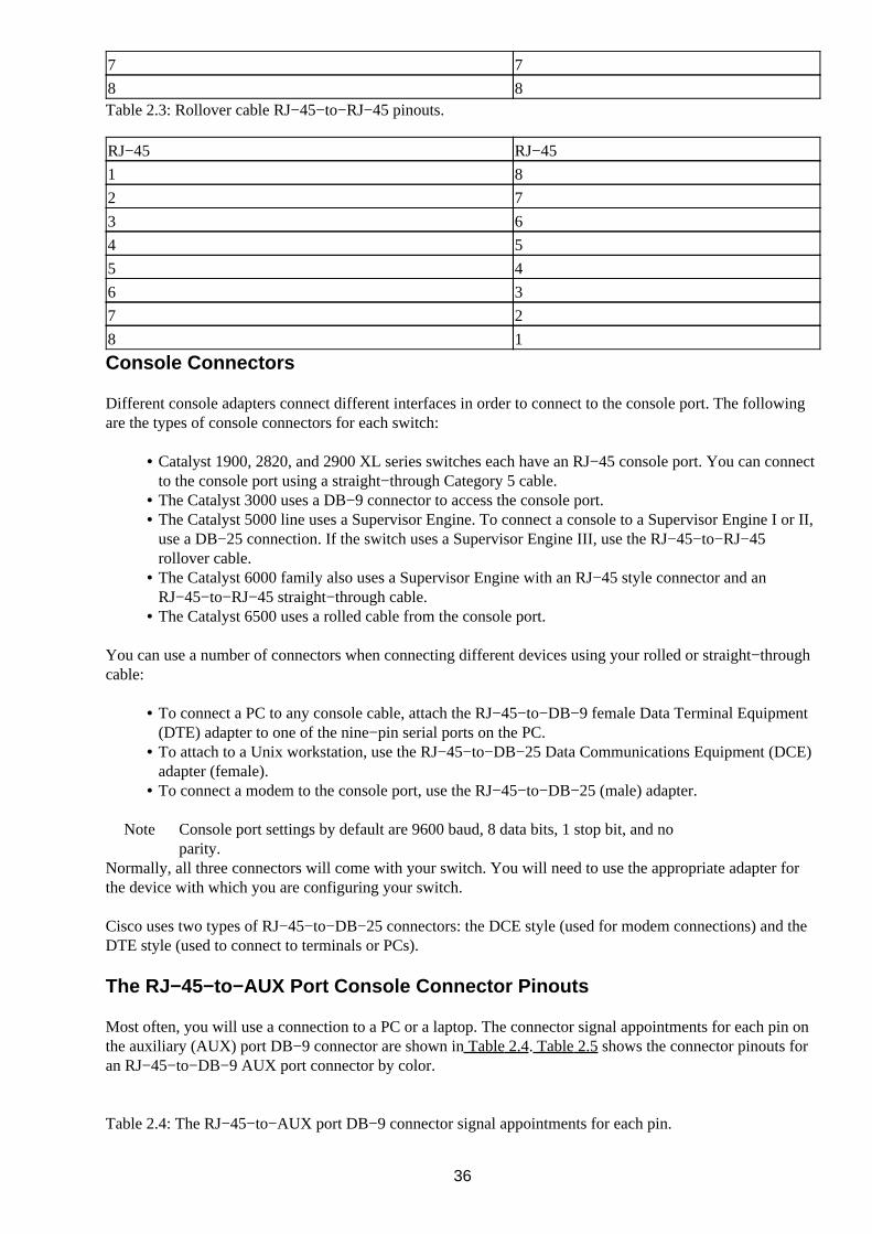
7 7
8 8Table 2.3: Rollover cable RJ−45−to−RJ−45 pinouts.
RJ−45 RJ−45
1 8
2 7
3 6
4 5
5 4
6 3
7 2
8 1
Console Connectors
Different console adapters connect different interfaces in order to connect to the console port. The followingare the types of console connectors for each switch:
Catalyst 1900, 2820, and 2900 XL series switches each have an RJ−45 console port. You can connectto the console port using a straight−through Category 5 cable.
•
The Catalyst 3000 uses a DB−9 connector to access the console port.• The Catalyst 5000 line uses a Supervisor Engine. To connect a console to a Supervisor Engine I or II,use a DB−25 connection. If the switch uses a Supervisor Engine III, use the RJ−45−to−RJ−45rollover cable.
•
The Catalyst 6000 family also uses a Supervisor Engine with an RJ−45 style connector and anRJ−45−to−RJ−45 straight−through cable.
•
The Catalyst 6500 uses a rolled cable from the console port.•
You can use a number of connectors when connecting different devices using your rolled or straight−throughcable:
To connect a PC to any console cable, attach the RJ−45−to−DB−9 female Data Terminal Equipment(DTE) adapter to one of the nine−pin serial ports on the PC.
•
To attach to a Unix workstation, use the RJ−45−to−DB−25 Data Communications Equipment (DCE)adapter (female).
•
To connect a modem to the console port, use the RJ−45−to−DB−25 (male) adapter.•
Note Console port settings by default are 9600 baud, 8 data bits, 1 stop bit, and noparity.
Normally, all three connectors will come with your switch. You will need to use the appropriate adapter forthe device with which you are configuring your switch.
Cisco uses two types of RJ−45−to−DB−25 connectors: the DCE style (used for modem connections) and theDTE style (used to connect to terminals or PCs).
The RJ−45−to−AUX Port Console Connector Pinouts
Most often, you will use a connection to a PC or a laptop. The connector signal appointments for each pin onthe auxiliary (AUX) port DB−9 connector are shown in Table 2.4. Table 2.5 shows the connector pinouts foran RJ−45−to−DB−9 AUX port connector by color.
Table 2.4: The RJ−45−to−AUX port DB−9 connector signal appointments for each pin.
36

Pin Signal Input/Output
1 RTS Out
2 DTR Out
3 TXD Out
4 GND N/A
5 GND N/A
6 RXD In
7 DSR In
8 CTS InTable 2.5: The RJ−45−to−DB−9 AUX port pinouts by color.
Color RJ−45 DB−9
Brown 1 6
Blue 2 7
Yellow 3 2
Green 4 5
Red 5 5
Black 6 3
Orange 7 4
White 8 8Table 2.6 shows the connectors most often used for modem connections. Table 2.7 shows the connectors mostoften used with Unix workstation connections to the console port.
Table 2.6: DCE connector pinouts for an RJ−45 to a DB−25 male.
RJ−45 DCE
1 5
2 8
3 3
4 7
5 7
6 2
7 20
8 4Table 2.7: DTE connectors for an RJ−45 to a DB−25 female.
RJ−45 DTE
1 4
2 20
3 2
4 7
5 7
6 3
7 6
8 5In the event that you need a DB−25−to−DB−9 connector, Table 2.8 shows the pinouts.
37

Table 2.8: DB−25−to−DB−9 connector pinouts.
DB−25 Signal DB−9
2 TXD 3
3 RXD 2
4 RTS 7
5 CTS 8
6 DSR 6
7 GND 5
8 DCD 1
20 DTR 4
Switch IOSs
Three types of Cisco operating systems are in use:
Set/Clear command interface—Found on models of the Catalyst 2926, 2926G, 2948G, 2980G, 4000,5000, 5500, 6000, and 6500 series of switches. They are called Set/Clear because most commands onthe switches start with set, clear, or show.
•
Cisco IOS−based Command Line Interface—Most closely resembles a Cisco router’s IOS CommandLine Interface. This interface is found on Catalyst 1900EN, 2820, 2900 XL, 8500, and 12000 seriesmodels.
•
Menu−driven—Found exclusively on the Catalyst 1900SE, 2820SE, 3000, 3100, and 3200 seriesswitches.
•
You have to do very little in order to get a Cisco switch to work. By default, the Set/Clear command setswitches and the Cisco CLI IOS interface switches have the following default attributes:
The prompt name is set to Console>.• No hostname is configured.• No passwords are set.• All ports default to VLAN1.• The console port has no IP information.• No contact name or location information is defined.• RMON is disabled.• SNMP traps are disabled.• SNMP community strings are set Public for read−only, Private for read−write, and Secret forread−write−all access.
•
VLAN Trunking Protocol (VTP) mode is set to Server.• No VTP domain or password is configured.• All VLANs are eligible for trunking.• Inter−Switch Link (ISL) defaults to Auto.•
The IOS Configuration Modes
The CLI of IOS−based switches is similar to that of IOS−based routers. Commands can be recalled by usingthe up or down arrows or by using a combination of Ctrl or Esc sequences to perform certain editing functionsin the command−line history buffers.
On an IOS−based switch, you can access many command modes to enter commands. Here are some of themore important modes:
EXEC mode—When you log in to a switch, you are automatically in User EXEC command mode.The EXEC commands are a subset of those available at the Privileged level. In general, EXECcommands allow you to test connectivity, perform basic tests, and list system information.
•
38

Privileged EXEC mode—The Privileged command set includes those commands contained in UserEXEC mode, as well as the configure command, through which you can access the remainingcommand modes. Privileged EXEC mode also includes high−level testing commands, such as debug.
•
Global Configuration mode—Global Configuration mode commands apply to features that affect thesystem as a whole. Use the configure privileged EXEC command to enter Global Configurationmode.
•
Interface Configuration mode—Many features are enabled on a per−interface basis. InterfaceConfiguration commands modify the operation of an interface such as an Ethernet port or a VLAN.
•
Configuring Passwords
Passwords can be configured on every access method to a Cisco Catalyst switch. Passwords can be applied tothe console port, auxiliary (AUX) port, and VTY lines.
Limiting Telnet Access
VTY access can be secured with a password. However, when a careless administrator walks away from alogged−in Telnet session, the door is open with full access to the entire network. This situation allows anyonewith access to the terminal the administrator was using to make changes and attack the network.
A solution is to add another layer of security. You can do this by applying a time−out condition to unusedVTY sessions. The Cisco IOSs calculate unused sessions in seconds or minutes, depending on the IOSversion. Should the session not receive a character input from the administrator’s session for the configuredamount of time, the session is closed, and the administrator using the session is logged out.
Implementing Privilege Levels
Privilege levels can be assigned to limit switch users’ ability to perform certain commands or types ofcommands. You can configure two types of levels in the IOS: user levels and privilege levels. A user levelallows a user to perform a subset of commands that does not allow for configuration changes or debugfunctions. A privilege level, on the other hand, allows the user to use all the available commands, includingconfiguration change commands.
You can assign a user 16 different levels, from level 0 to level 15. Level 1 is set to User EXEC Mode bydefault. This level gives the user very limited access, primarily to show commands. Level 15 defaults toPrivileged EXEC mode, which gives the user full access to all configuration commands in the IOS (includingthe debug command).
Privilege level 0 is a special level that allows the user to use a more specific defined set of commands. As anexample, you could allow a certain user to use only the show arp command. This command is useful when athird party is using a sniffer on your network and needs to match a MAC address to an IP address and viceversa.
Configuring an IOS−Based CLI Switch
In this section, we will walk through the basic configuration of the IOS−based CLI switches. Although thesetasks are not all mandatory, knowing them will help you to better manage your switches.
39
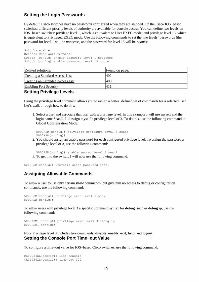
Setting the Login Passwords
By default, Cisco switches have no passwords configured when they are shipped. On the Cisco IOS−basedswitches, different priority levels of authority are available for console access. You can define two levels onIOS−based switches: privilege level 1, which is equivalent to User EXEC mode; and privilege level 15, whichis equivalent to Privileged EXEC mode. Use the following commands to set the two levels’ passwords (thepassword for level 1 will be noaccess, and the password for level 15 will be noone):
Switch> enableSwitch# Configure terminalSwitch (config) enable password level 1 noaccessSwitch (config) enable password level 15 noone
Related solutions: Found on page:
Creating a Standard Access List 402
Creating an Extended Access List 403
Enabling Port Security 411
Setting Privilege Levels
Using the privilege level command allows you to assign a better−defined set of commands for a selected user.Let’s walk through how to do this:
Select a user and associate that user with a privilege level. In this example I will use myself and thelogin name SeanO. I’ll assign myself a privilege level of 3. To do this, use the following command inGlobal Configuration Mode:
5000RSM(config)# privilege configure level 3 seano5000RSM(config)#
1.
You should assign an enable password for each configured privilege level. To assign the password aprivilege level of 3, use the following command:
5000RSM(config)# enable secret level 3 sean1
2.
To get into the switch, I will now use the following command:3.
5000RSM(config)# username seano password sean1
Assigning Allowable Commands
To allow a user to use only certain show commands, but give him no access to debug or configurationcommands, use the following command:
5000RSM(config)# privilege exec level 3 show5000RSM(config)#
To allow users with privilege level 3 a specific command syntax for debug, such as debug ip, use thefollowing command:
5000RSM1(config)# privilege exec level 3 debug ip5000RSM1(config)#
Note Privilege level 0 includes five commands: disable, enable, exit, help, and logout.Setting the Console Port Time−out Value
To configure a time−out value for IOS−based Cisco switches, use the following command:
CAT2924XL(config)# line consoleCAT2924XL(config)# time−out 300
40

The time−out value is now set to five minutes, using seconds.
Tip You can use the lock command to lock an unused Telnet session. After you issue the lockcommand, the system will ask you to enter and verify an unlocking password.
To configure a Set/Clear command−based switch to five minutes, use the following command:
CAT5009(enable) set logout 5
To configure the time−out value to five minutes on the console port of an IOS−based route processor orrouter, use the following command:
5000RSM(config)# line console 05000RSM(config−line)# exec−timeout 5
Configuring the Telnet Time−out Value
To configure the time−out value to five minutes on the VTY port of an IOS−based route processor or router,use the following command:
5000RSM(config)# line vty 0 45000RSM(config−line)# exec−timeout 5
Tip To configure seconds beyond a minute, you can add an additional value to the command. For example, ifyou want the exec−timeout to be 5 minutes and 10 seconds, the command is exec−timeout 5 10.
Configuring the Hostname
On a Cisco IOS−based switch, configure the hostname using the following command in Global Configurationmode:
Switch (config) hostname CORIOLIS8500CORIOLIS8500>
Configuring the Date and Time
To set the system clock on an IOS−based switch and to put it in the PST time zone, use the followingcommand:
CORIOLIS8500(config) clock set 22:09:00 08 Oct 00CORIOLIS8500(config) clock timezone PST −8
Configuring an IP Address and Netmask
To configure an IP address on a Cisco IOS−based switch, enter the following commands in GlobalConfiguration mode (the IP address being used is 68.187.127.254 and the subnet mask is 255.255.0.0):
CORIOLIS8500(config) interface vlan 1CORIOLIS8500(config−int) ip address 68.187.127.254 255.255.0.0CORIOLIS8500(config−int) exit
Configuring a Default Route and Gateway
To configure the default route for data routing out of the subnet or VLAN, enter the following commands (theaddress of the local router is 68.187.127.1):
CORIOLIS8500(config) ip default−gateway 68.187.127.1CORIOLIS8500(config) end
41

Configuring Port Speed and Duplex
To configure the port speed—whether 10Mbps or 100Mbps—use the following commands:
CORIOLIS5500(config) interface fastethernet 2/3CORIOLIS5500(config−int) speed 100CORIOLIS5500(config−int) duplex full
The auto command can be used when the port on the other side is manually set. Links should not beconfigured with the auto setting on both devices connecting the links because both sides will try to determinethe speed on the other side of the link and neither will agree.
You can change the port duplex from full duplex to half duplex, as shown in the following commands:
CORIOLIS8500(config) interface fastethernet 0/1 CORIOLIS8500(config−int) speed autoCORIOLIS8500(config−int) duplex half
Enabling SNMP Contact
To set the SNMP contact for RMON support, configure your switch with a contact name, location, and chassisidentification to make the device easily identifiable by an SNMP management station. You can set the SNMPsystem contact, location, serial number, and, most importantly, the community that is the same as thecommunity configured on your SNMP management station. You can configure these items as shown here inthe same order as discussed, from the Global Configuration mode prompt:
CORIOLIS8500(config) snmp−server contact Joe SnowCORIOLIS8500(config) snmp−server location Coriolis Wiring ClosetCORIOLIS8500(config) snmp−server chassis−id 987654321CORIOLIS8500(config) snmp−server community coriolis
Configuring a Set/Clear−Based CLI Switch
In this section, you’ll walk through the basic configuration of the Set/Clearcommand−based CLI switches. Although these tasks are not all mandatory, completing them will help you tobetter manage your switches.
Logging On to a Switch
To begin configuring your switch, do the following:
Connect the console cable and connector to a terminal or PC and power on the switch. The switch willthen go through its initial POST, which runs diagnostics and checks for the reliability of the switchcomponents.
1.
Once the POST has completed successfully, the initial prompt should show a User EXEC modeprompt:
Enter Password:
2.
No password has been configured at this point, so just press the Enter key to continue.3. Cisco switches have two levels of access by default: User EXEC mode and Privileged EXEC mode.User EXEC mode will allow you to do some basic tasks, such as show the port or VLAN information.To get more advanced configuration options, you will need to enter Privileged EXEC mode. Use thefollowing command to enter Privileged EXEC mode:
4.
42

Console> enableEnter password:
Because you have not yet set a Privileged EXEC mode password, pressing Enter will put you intoPrivileged EXEC mode. The console will show the following prompt:
5.
Console> (enable)
You are now in Privileged EXEC mode.
Warning Starting here, all configuration changes are executed and saved to memory immediately.
•
Setting the Login and Enable Passwords
Because you don’t want the janitor coming in and trying to configure your networks, you need to configure apassword. You should close your security hole to prevent unauthorized access to your switch.
To set a password for user access, enter the following command in Privileged EXEC mode (the newpassword is noaccess):
Console> (enable) set passwordEnter old password: <press enter>Enter new password: noaccessRetype new password: noaccessPassword changed.
1.
Now add an additional layer of security by changing the password to enter Privileged EXEC mode onyour switch. It looks similar to the User EXEC mode change. For security purposes, the password willbe masked. To change the Privileged EXEC mode password, enter the following (set the password asnoone):
Console> (enable) set enablepassEnter old password: <press enter>Enter new password: nooneRetype new password: noonePassword changed.
2.
Tip At any time, you can type “?” or “help” to access the CLI help facility. For help on specificcommands, you can enter the command followed by a question mark; for example, set ? or sethelp.
Related solutions: Found on page:
Creating a Standard Access List 402
Creating an Extended Access List 403
Enabling Port Security 411
Changing the Console Prompt
The switch prompt is set by default to Console>. To help you to identify the switch you areconfiguring—especially when you Telnet into your switch—you should name the switch prompt somethingthat identifies it. If you fail to identify the switch correctly, it can be pretty embarrassing to work on the wrongswitch. To change your hostname to CORIOLIS5000, use the following command:
Console(enable) set prompt CORIOLIS5000CORIOLIS5000(enable)
Remember, you are still in Privileged EXEC mode, and the change will take place immediately.
43

Entering a Contact Name and Location Information
Next, let’s set the contact name for the person or organization that is administering this switch. Use thefollowing commands to set the switch contact and location:
CORIOLIS5500(enable) set system contact Joe SnowCORIOLIS5500(enable) set system location Coriolis Wiring Closet
Configuring System and Time Information
For troubleshooting with SNMP and Cisco Discovery Protocol (CDP), you need to configure systeminformation to identify the switch. By setting the correct date and time, you can be assured that error or logmessages will be accurate. To make changes to the system information, use the following commands:
CORIOLIS5500(enable) set system name CORIOLIS−5500CORIOLIS5500(enable) set time Sun 10/08/00 23:59:00
Configuring an IP Address and Netmask
Before you can Telnet, ping, or manage the switch remotely, you need to define an IP address and netmask forthe console port and assign it to a VLAN. By default, the switch console is in VLAN1. The syntax for settingup a console interface is:
set interface sc0 [vlan] [ip address] [subnet mask] [broadcast address]
For example, to set up a console with the IP address 68.187.127.1 and a netmask of 255.255.255.0 in VLAN2,you would enter the following command:
Console (enable) set interface sc0 2 68.187.127.1 255.255.255.0 Interface sc0 vlan set, IP address and netmask set.
Note It is only necessary to enter the broadcast address if the address entered is something other than a ClassA, B, or C address.
Serial Line Internet Protocol (SLIP) access can also be set up for the console port. SLIP is an older method ofconnecting to network devices. When you configure the SLIP (sl0) interface, you can open a point−to−pointconnection to the switch through the console port from a workstation. The command syntax for configuring aSLIP interface is:
set interface sl0 slip_addr dest_addr
To configure a SLIP interface, enter the following:
Console> (enable) set interface sl0 68.187.127.1 68.187.127.2Interface sl0 slip and destination address set.Console> (enable) slip attachConsole Port now running SLIP.
The console port must be used for the SLIP connections. If you use the console port to access the switch whenyou enter the slip attach command, you will lose the console port connection. When the SLIP connection isenabled and SLIP is attached on the console port, an Electronic Industries Association/TelecommunicationsIndustry Association−232 (EIA/TIA−232) or dumb terminal cannot connect through the console port.
To see the interface IP information that has been configured, use the following command:
Console> (enable) show interfacesl0: flags=51<UP,POINTOPOINT,RUNNING> slip 68.187.127.1 dest 68.187.127.2
44

sc0: flags=63<UP,BROADCAST,RUNNING> vlan 1 inet 68.187.127.1 netmask 255.255.255.0 broadcast 68.187.127.1 Console> (enable)
Configuring a Default Route and Gateway
Data traffic not addressed to the local subnet or VLAN must be sent to a default route or destination. Forredundancy purposes, a secondary default gateway can be configured if the primary gateway link is lost. Theswitch attempts to use the secondary gateways in the order they were configured, unless the syntax primary isused. The switch will send periodic pings to determine if each gateway has lost connectivity. If the primarygateway loses its link, it begins forwarding to the secondary default gateway. When connectivity to theprimary gateway link is restored, the switch resumes sending traffic to the primary gateway.
You can define up to three default IP gateways. The first gateway configured becomes the primary defaultgateway. If multiple gateways are defined, the last primary gateway configured is the primary defaultgateway. You can also use the primary subcommand to make a certain IP address the defined primary defaultgateway. The rest become secondary in the event of a network problem, as shown here:
Console> (enable) set ip route default 68.187.127.1Route added.Console> (enable) set ip route default 68.187.127.2 primaryRoute added.
Viewing the Default Routes
The following command allows you to see the default routes on both the Cisco IOS−based command−lineinterfaces:
Console> (enable) show ip route
Fragmentation Redirect Unreachable————————————— ———————— ———————————enabled enabled enabled
The primary gateway: 68.187.127.1Destination Gateway RouteMask Flags Use Interface——————————— ——————— ————————— ————— ————— —————————default 68.187.127.1 0x0 UG 100 sc0default 68.187.127.2 0x0 G 0 sc0
Configuring Port Speed and Duplex
You can manually set 10Mbps and 100Mbps ports. Occasionally, you will find an interface that cannotautonegotiate the speed correctly. You can choose from three syntaxes:
10—10Mbps traffic only• 100—100Mbps traffic only• auto—Autonegotiates the speed of the traffic on the port•
Let’s take a look at some examples. To configure port 3 on module 2 to auto−negotiate, use the followingcommand:
Console? (enable) set port speed 2/3 autoPort 2/3 set to auto−sensing mode.
You can also enter multiple ports’ consecutive port numbers. The following example configures ports 1through 8 on the same line card used in the previous example to 100Mbps:
45

SeansSwitch (enable) set port speed ? <mod/port> Module number and Port number(s)SeansSwitch (enable) set port speed 2/1 ? auto Set speed to auto <port_speed> Port speed (4, 10, 16, 100 or 1000)SeansSwitch (enable) set port speed 2/1−8 100Ports 2/1−8 transmission speed set to 100Mbps.SeansSwitch (enable)
To manually configure a line card port to full duplex, use the following command:
SeansSwitch (enable) set port duplex ? <mod/port> Module number and Port number(s)SeansSwitch (enable) set port duplex 2/1 ? full Full duplex half Half duplexSeansSwitch (enable) set port duplex 2/1 fullPort(s) 2/1 set to full−duplex.SeansSwitch (enable)
Note The possible syntaxes are full or half, representing full duplex or half duplex.
Enabling SNMP
SNMP is used by SNMP management stations to monitor network devices such as switches. By configuringoperating thresholds, you can configure SNMP to generate trap messages when changes or problems occur ona switch.
There are three levels of access for configuring SNMP. The levels of access are defined by the informationconfigured on the switch; the accessing management station must abide by those given sets of rights. Thelevels can be defined with community string configuration or by trap receivers, as follows:
Read−only—Allows management stations to read the SNMP information but make no configurationchanges.
•
Read−write—Allows management stations to set SNMP parameters on the switch with the exceptionof community strings.
•
Read−write−all—Allows complete access to the switch. The SNMP management stations can alterall information and community strings.
•
The following commands are examples of how to configure all three types of access and set the functions ofthe SNMP management stations:
Console> (enable) set snmp community read−only publicSNMP read−only community string set to Ôpublic’.Console> (enable) set snmp community read−write public2SNMP read−write community string set to Ôpublic2’.Console> (enable) set snmp community read−write−all public3SNMP read−write−all community string set to Ôpublic3’.
Configuring Trap Message Targets
You can configure trap message receivers by specifying the IP address of each receiver and the access typeallowed. You must then enable SNMP traps, as shown here:
Console> (enable) set snmp trap 68.187.127.6 read−write−allSNMP trap receiver added.Console> (enable) set snmp trap 68.187.127.4 read−writeSNMP trap receiver added.Console> (enable) set snmp trap enable allAll SNMP traps enabled.
46

Configuring a Menu−Driven IOS
The Catalyst 3000 series has a menu−driven switch interface, which allows you to use the arrow keys on yourkeyboard to select the different options used to configure the switch. As with the other two types of interfaces,you need to connect the switch to a dumb terminal or PC. This switch, however, supports a process known asautobaud, which allows you to press the Enter key several times to get the switch’s attention. The switch willthen automatically configure the console port to the correct baud rate. Here’s how to do it:
The first screen you come to shows the MAC address assigned to the switch and the system contact,and asks you to type in the password. If this is the initial configuration, press the Enter key tocontinue. This will bring you to the Main menu, shown in Figure 2.3. No password is configuredwhen the switch has just been loaded with a new IOS or straight out of the box.
Figure 2.3: : The main menu of the menu−driven IOS.
1.
Because you are going to configure the switch, choose the Configuration option. You are presentedwith two options. You can choose either Serial Link Configuration to configure the console port, orTelnet Configuration to configure Telnet.
When you enter the Configuration menu, you will notice that you are given the option to configureyour switch for options that are not available without certain add−on or module cards for your switch.This is more evident if you have the Enhanced Feature Set, which is now the standard for the Cisco3000 series. Without the Enhanced Feature Set, you will not have VLAN and EtherChannel menuoptions. In this example you’ll be configuring a Cisco 3000 series switch with the Enhanced FeatureSet, as depicted in Figure 2.4.
Figure 2.4: The Configuration menu of the menu−driven IOS.
Tip If you make a mistake in your configuration, you can use Ctrl+P to exit the switchwithout saving changes. Use the Exit Console or Return To Previous Menu option tosave your changes and exit the switch configuration mode.
2.
You have the option of choosing a time−out value for the console session. If you would like to disabletime−outs, enter a zero. Otherwise, enter a time in minutes from 1 to 1,440.
3.
47

Configuring the Console Port
To configure the Console port, do the following:
Choose Configuration|Serial Configuration.1. As shown in Figure 2.5, you can configure four options: the Hardware Flow Control, the SoftwareFlow Control, the Autobaud Upon Break feature, and the Console Baud Rate. Under normalcircumstances, you will never change these defaults. However, the option you probably won’t befamiliar with—and which Cisco recommends not changing—is the Autobaud Upon Break feature. Byenabling this feature, you force the switch to automat−ically sense the baud rate of the switch bypressing the Break key on the PC or dumb terminal. You can set the baud rate on the switch from2,400 to 57,600 baud.
2.
Figure 2.5: : The Console Port Serial Link configuration screen.
Configuring Telnet
To configure Telnet, do the following:
Using a Telnet emulator supporting VT100 or VT200, use Telnet to access your switch configuration.1. Choose Configuration|Console Configuration. The Telnet Configuration screen appears. This screenallows you to configure three options:
The number of Telnet sessions allowed simultaneously, from 0 to 5♦ The switch to disallow new Telnet sessions♦ The ability to terminate all Telnet sessions♦
2.
Tip Disallowing new Telnet sessions is a great feature to invoke when you are configuring or upgrading theswitch. That way, another administrator can’t come in and try to change the configuration while you areworking on the switch.
Configuring the Password
The Password menu is available from the Configuration menu. It has just two options, and only one passwordneeds to be configured for the whole switch. You can set or delete the password.
When changing the password, you will need to supply the current password. If no password is configured, justpress Enter. You will then be asked for the new password. The new password can be up to 15 characters long.
Configuring an IP Address and Default Gateway
Configuring the default gateway and the IP address on the menu−driven IOS is pretty straightforward, as well.As you can see from Figure 2.6, the MAC address comes preconfigured; you need only enter the IP address,subnet mask, and default gateway of your router or route processor for individual VLANs you haveconfigured.
48

Figure 2.6: The menu−driven VLAN IP configuration screen.Related solutions: Found on page:
Creating a Standard Access List 402
Creating an Extended Access List 403
Enabling Port Security 411
Configuring SNMP
You can configure up to 10 community strings on the menu−driven switch IOS by following these steps:
Enter the appropriate IP configurations as shown in Configuring an IP Address and Default Gateway.1. Select Configuration|SNMP Configuration. You are then presented with three configuration options:Send Authentication Traps, Community Strings, or Trap Receivers. As with the SNMP configurationson the other two IOS configurations, we will concern ourselves with the configuration necessary toreceive information to our SNMP management station.
2.
Choose the option Community Strings. The screen shown in Figure 2.7 will appear.3.
Figure 2.7: The Community Strings configuration screen.
You have five options at the bottom of the screen:• Return—Automatically saves the configuration and returns to the Main menu.• Add Entry—Allows you to add an SNMP entry and the mode.•
Note The Mode option allows you to configure two modes. R (for read access) allows a managementstation to receive messages but make no configuration changes. W (for write access) allows theSNMP management station to receive messages and make configuration changes.
Delete Entry—Deletes the highlighted community string.• Change Entry—Allows you to modify a community string entry.• Clear Table—Deletes all community string entries.•
49

Configuring ROM
ROM monitor is a ROM−based program that can be configured to execute upon the following conditions:
Upon boot−up• Upon recycling the switch power• When a fatal exception error occurs• When the switch fails to find a valid system image• If the nonvolatile RAM (NVRAM) configuration is corrupt• If the configuration register is set to enter ROM monitor mode•
The ROM monitor CLI is present only on the Supervisor Engine III, Catalyst 4000, and the 2948G seriesswitch Supervisor Engine modules. When the switch is in the ROM monitor mode, the switch will allow youto load a system image manually from Flash memory, from a Trivial File Transfer Protocol (TFTP) file, orfrom the bootflash.
Entering ROM Configuration Mode
You can enter ROM configuration mode by using one of these two methods:
Cycle the power on the switch and press the Break key during the first 60 seconds of startup. (TheBreak key is enabled for the first 60 seconds after cycling the power on the switch.)
•
Enter ROM mode through a terminal server, using Telnet or another terminal emulation program.Enter the break command as soon as the power is cycled on the switch.
•
ROM monitor has its own unique prompt that informs you when you have entered ROM monitor mode. Theprompt you will see when you have entered ROM configuration mode is rommon>.
Booting ROM Mode from a Flash Device
To boot from a flash device, you can use the following syntax, which is shown in Table 2.9:
boot [−xv] [device][imagename]
Table 2.9 : The boot command syntaxes.
Syntax Meaning
−x Identifies the image to load but not execute
−v Identifies a need to use verbose mode
device Identifies the device
imagename Identifies the image to useThe image name is optional. If no image name is presented, the system defaults to the first valid file in thedevice. Remember that file names are case sensitive. Let’s look at an example of using this command:
rommon> boot −x bootflash:cat5000−sup2.2−2.binCCCCCCCCCCCCCCCCCCCCCCCCCCCCCCCCCCCCCCCCCCCCCCCCCCCCCCCCCCCCUncompressing file:#####################################################################################################################################################################################################################
50

Configuring SNMP
RMON works in conjunction with SNMP and requires a protocol analyzer or probe to use its full features. Touse SNMP−based monitoring, you need to verify that SNMP is running on your IOS−based switch.
Verify that SNMP is running, using the following command in User or EXEC mode:
show snmp
1.
Enable SNMP and allow read−only access to hosts using the public SNMP string by using thiscommand in Configuration mode:
snmp−server community public
2.
After enabling SNMP, you need to define a host IP address to send SNMP trap messages. Here is anexample:
3.
snmp server host 130.77.40.05 public
Configuring RMON
To configure RMON, use the following steps:
To show RMON statistics on a certain interface, use the followingcommand:
show rmon statistics
This command shows statistics for the number of packets, octets, broadcast packets, and multicastpackets received, as well as errors detected and packet lengths received.
1.
Configure the SNMP community using this command:
set snmp community <read−only|read−write|read−write−all> <community string>
2.
Assign the SNMP log server responsible for receiving traps with this command:3.
set snmp trap <hostaddress> <community−string>
Configuring RMON on a Set/Clear−Based Interface
To configure RMON on a Set/Clear−based interface, perform the following steps:
On a Set/Clear command−based interface, configure the SNMP community using this command:
set snmp community <read−only|read−write|read−write−all> <community string>
1.
Assign the SNMP log server responsible for receiving traps with the following command:
set snmp trap <hostaddress> <community−string>Enable snmp with "set snmp enable"Console> (enable) set snmp rmon enableSNMP RMON support enabled.Console> (enable) show snmpRMON: EnabledExtended RMON: Extended RMON module is not presentTraps Enabled: Port,Module,Chassis,Bridge,Repeater,Vtp,Auth,ippermit,Vmps,config, entity,stpxPort Traps Enabled: 1/1−2,3/1−8Community−Access Community−String ———————————————— ————————————————read−only Everyone
2.
51

read−write Administratorsread−write−all RootTrap−Rec−Address Trap−Rec−Community———————————————————————————— ————————————————————168.187.127.4 read−write168.187.127.6 read−write−allConsole> (enable)
To verify that RMON is running, use the following command in EXEC mode:3.
show rmon
Using Set/Clear Command Set Recall Key Sequences
The CLI of a Set/Clear interface is based on Unix, so certain c−shell commands can be issued to recallcommands previously issued. The switch by default stores the previous 20 commands in its buffer. Unlike theCisco IOS routers or switches, the up arrows do not work. You can, however, use the key sequences shown inTable 2.10 to recall or modify commands:
Table 2.10 : Command recall key sequences.
Command Action
!! Repeats the last command
!−nn Repeats the nnth number of commands
!n Repeats command n in the list
!zzz Repeats the command that starts with the zzz string
!?zzz Repeats the command containing the zzz string
^yyy^zzz Replaces the string yyy with zzz in the previous command
!!zzz Adds the string zzz to the previous command
!n zzz Adds the string zzz to command n
!yyy zzz Adds the string zzz to the end of the command that beginswith yyy
!?yyy zzz Adds the string zzz to the end of the command containingyyy
Using IOS−Based Command Editing Keys and Functions
In the Cisco IOS, certain keys allow you to edit or change the configuration. The keys and their functions arelisted in Table 2.11.
Table 2.11: Cisco IOS basic command editing keys and functions.
Key Function
Tab Completes a partial command name
Delete Erases the character to the left of the cursor
Return Performs a command
Space Scrolls down a page
Left arrow Moves a character to the left
Right arrow Moves a character to the right
52

Up arrow Recalls commands in the history buffer
Down arrow Returns to more recent commands
Ctrl+A Moves to the beginning of a line
Ctrl+B Moves back one character
Ctrl+D Deletes a character
Ctrl+E Moves to the end of the command line
Ctrl+F Moves forward one character
Ctrl+K Deletes all characters to the end of the line
Ctrl+L Redisplays the system prompt and command line
Ctrl+T Transposes the character to the left of the cursor withthe character at the cursor
Ctrl+U Deletes all characters to the beginning
Ctrl+V Indicates that the next keystroke is a command
Ctrl+W Deletes to the left of the cursor
Ctrl+Y Recalls the most recently deleted command
Ctrl+Z Ends the configuration mode and returns you toEXEC mode
53

Chapter 3: WAN Switching
In Depth
Switches are not only used in LAN networks; they are also used extensively in wide area networks (WANs).Chapters 1 and 2 gave you an overview of LAN switching. Well, WAN switching is the same in some waysand completely different in others.
In an Ethernet switching environment, the switch utilizes Carrier Sense Multiple Access with CollisionDetection (CSMA/CD). The switch or host sends out a packet and detects if a collision occurs. If there is acollision, the sender waits a random amount of time and then retransmits the packet. If the host does not detecta collision, it sends out the next packet. You may think that if the switch or host is set to full−duplex, therewill be no collision—that is correct, but the host still waits between sending packets.
In a Token Ring switching environment, a token is passed from one port to the next. The host must havepossession of the token to transmit. If the token is already in use, the host passes the token on and waits for itto come around again. All stations on the network must wait for an available token. An active monitor, whichcould be any station on the segment, performs a ring maintenance function and generates a new token if theexisting token is lost or corrupted.
As you can see, both Token Ring and Ethernet switching require the node to wait. The node must wait eitherfor the token or for the frame to reach the other nodes. This is not the most efficient utilization of bandwidth.In a LAN environment, this inefficiency is not a major concern; in a WAN, it becomes unacceptable. Can youimagine if your very expensive T1 link could be used only half the time? To overcome this problem, WANlinks utilize serial transmission.
Serial transmission sends the electric signal (bits) down the wire one after another. It does not wait for oneframe to reach the other end before transmitting the next frame. To identify the beginning and the end of theframe, a timing mechanism is used. The timing can be either synchronous or asynchronous. Synchronoussignals utilize an identical clock rate, and the clocks are set to a reference clock. Asynchronous signals do notrequire a common clock; the timing signals come from special characters in the transmission stream.
Asynchronous serial transmissions put a start bit and a stop bit between each character (usually 1 byte). Thisis an eight−to−two ratio of data to overhead, which is very expensive in a WAN link.
Synchronous serial transmissions do not have such high overhead, because they do not require the specialcharacters; they also have a larger payload. Are synchronous serial transmissions the perfect WANtransmission method? No; the problem lies in how to synchronize equipment miles apart. Synchronous serialtransmission is only suitable for distances where the time required for data to travel the link does not distortthe synchronization.
So, first we said that serial is the way to go, and now we’ve said that serial has either high overhead or cannottravel a long distance. What do we use? Well, we use both, and cheat a little bit. We use synchronous serialtransmission for a short distance and then use asynchronous for the remaining, long distance. We cheat byputting multiple characters in each frame and limiting the overhead.
When a frame leaves a host and reaches a router, the router uses synchronous serial transmission to pass theframe on to a WAN transmission device. The WAN device puts multiple characters into each WAN frame andsends it out. To minimize the variation of time between when the frames leave the host and when they reachthe end of the link, each frame is divided and put into a slot in the WAN frame. This way, the frame does nothave to wait for the transmission of other frames before it is sent. (Remember, this process is designed tominimize wait time.) If there is no traffic to be carried in a slot, that slot is wasted. Figure 3.1 shows a diagramof a packet moving from LAN nodes to the router and the WAN device.
54

Figure 3.1: A packet’s journey from a host to a WAN device. The WAN transmission is continuous and doesnot have to wait for acknowledgement or permission.Let’s take a look at how this process would work in a T1 line. T1 has 24 slots in each frame; each slot is 8bits, and there is 1 framing bit:
24 slots x 8 bits + 1 framing bit = 193 bits
T1 frames are transmitted 8,000 frames per second, or one frame every 125 microseconds:
193 bits x 8,000 = 1,544,000 bits per second (bps)
When you have a higher bandwidth, the frame is bigger and contains more slots (for example, E1 has 32slots). As you can see, this is a great increase in the effective use of the bandwidth.
Another asynchronous serial transmission method is Asynchronous Transfer Mode (ATM). ATM is acell−based switching technology. It has a fixed size of 53 octets: 5 octets of overhead and 48 octets ofpayload. Bandwidth in ATM is available on demand. It is even more efficient relative to the serialtransmission method because it does not have to wait for assigned slots in the frame. One Ethernet frame canconsist of multiple consecutive cells. ATM also enables Quality of Service (QoS). Cells can be assigneddifferent levels of priority. If there is any point of congestion, cells with higher priority will have preference tothe bandwidth. ATM is the most widely used WAN serial transmission method.
Note ATM is covered in more detail in Chapter 8.
WAN Transmission Media
The physical transmission media that carry the signals in WAN are divided into two kinds: narrowband andbroadband. A narrowband transmission consists of a single channel carried by a single medium. A broadbandtransmission consists of multiple channels in different frequencies carried on a single medium.
The most common narrowband transmission types are T1, E1, and J1. See Table 3.1 for the differences amongthe transmission types and where each is used. The time slots specify how much bandwidth (bit rate) thenarrowband transmissions have.
Table 3.1: Narrowband transmission types.
Transmission Type Number of Slots Bit Rate Region
T1 24 1.544Mbps North America
E1 32 2.048Mbps Africa, Asia (not includingJapan), Europe, Australia,South America
J1 32 2.048Mbps JapanNarrowband is most commonly used by businesses as their WAN medium because of its low cost. If morebandwidth is needed than narrowband can provide, most businesses use multiple narrowband connections.
55

The capability of broadband to carry multiple signals enables it to have a higher transmission speed. Table 3.2displays the various broadband transmissions, which require more expensive and specialized transmitters andreceivers.
Table 3.2: The different broadband transmission types and their bandwidth.
Transmission Type Bit Rate
DS2 6.312Mbps
E2 8.448Mbps
E3 34.368Mbps
DS3 44.736Mbps
OC/STS−1 51.840Mbps
OC/STS−3 155.520Mbps
OC/STS−9 466.560Mbps
OC/STS−12 622.080Mbps
OC/STS−18 922.120Mbps
OC/STS−24 1.244Gbps
OC/STS−36 1.866Gbps
… …
OC/STS−768 39.820GbpsDigital signal 2 (DS2), E2, E3, and DS3 describe digital transmission across copper or fiber cables. OC/STSresides almost exclusively on fiber−optic cables. The OC designator specifies an optical transmission,whereas the STS designator specifies the characteristics of the transmission (except the optical interface).There are two types of fiber−optic media:
Single−mode fiber—Has a core of 8.3 microns and a cladding of 125 microns. A single light wavepowered by a laser is used to generate the transmission. Single−mode can be used for distances up to45 kilometers; it has no known speed limitation. Figure 3.2 shows an example of a single−mode fiber.
•
Figure 3.2: Single mode fiber.
Multimode fiber—Has a core of 62.5 microns and a cladding of 125 microns. Multiple light wavespowered by a light−emitting diode (LED) are used to power the transmission. Multimode has adistance limit of two kilometers; it has a maximum data transfer rate of 155Mbps in WANapplications. (It has recently been approved for use for Gigabit Ethernet.) Figure 3.3 shows anexample of a multimode fiber. The core and cladding boundary work as a mirror to reflect the lightwaves down the fiber.
•
Figure 3.3: Multimode fiber.
Synchronous Transport Signal (STS)
Synchronous transport signal (STS) is the basic building block of the Synchronous Optical Network(SONET). It defines the framing structure of the signal. It consist of two parts: STS overhead and STSpayload. In STS−1, the frame is 9 rows of 90 octets. Each row has 3 octets of overhead and 87 octets ofpayload, resulting in 6,489 bits per frame. A frame occurs every 125 microseconds, yielding 51.84Mbps.
56

STS−n is an interleaving of multiple (n) STS−1s. The size of the payload and the overhead are multiplied byn. Figure 3.4 displays an STS diagram.
Figure 3.4: The STS−1 framing and STS−n framing. The overhead and payload are proportionate to the nvalue, with the STS−1 frame as the base.You may wonder why we’re talking about synchronous transmission when we said it is only used over shortdistances. Where did the asynchronous transmission go? Well, the asynchronous traffic is encapsulated in theSTS payload. The asynchronous serial transmission eliminates the need for the synchronization of the endtransmitting equipment. In SONET, most WAN links are a point−to−point connection utilizing light as thesignaling source. The time required for the signal to travel the link does not distort the synchronization. TheOC−n signal itself is used for the synchronization between equipment. This combination of asynchronous andsynchronous serial transmission enables signals to reach across long distances with minimal overhead.
Cisco WAN Switches
The current Cisco WAN product line consists of the following switches:
MGX 8200 series• IGX 8400 series• BPX 8600 series wide−area switches• MGX 8800 series wide−area edge switches•
MGX 8200 Series
The Cisco MGX 8200 series is designed to function as a WAN edge device. It combines multiple narrowbandtransmissions into a single broadband trunk. It functions as a standalone unit to connect to the ATM networkor it can be used as a feeder device to other WAN switches. The series consists of the MGX 8220 EdgeConcentrator, the MGX 8240 Private Line Service Gateway, and the MGX 8260 Media Gateway.
The MGX 8220 Edge Concentrator has 16 slots with the capability for full redundancy. It accepts two classesof modules: common control cards and function modules. Six slots are reserved for common control cards,and 10 slots are reserved for function modules. The common control card consists of an AXIS ShelfController (ASC) card, a Service Resource Module (SRM) card, and a service trunk card. Each card can useeither of two specific slots. When both slots are occupied, one of them acts as a hot standby. The ASC cardprovides a user interface for the overall control, configuration, and management of the unit. The SRM controlsthe flow of traffic from the trunk card to various function modules. The service trunk module is the onlybroadband interface (OC−3 or T3) that transports the aggregated traffic to the ATM network. The functionmodules are narrowband interface cards. The narrowband transmission can be T1, high−speed Frame Relay,
57

ATM frame user−network interface (UNI), or System Network Architecture (SNA).
The MGX 8240 Private Line Service Gateway is designed to terminate private lease lines (T1, T3, or DS0). Ithas 16 slots with 1 reserved for a redundant control card. It can support up to 1,260 channelized T1s. It isdesigned for large Internet service providers (ISPs) to aggregate dial−in traffic, which is delivered by the localcentral office’s Class 4 or Class 5 switch in a T1 or T3 interface. The combined traffic is delivered to thebroadband network via OC−3 trunk ports.
The MGX 8260 Media Gateway is a high−density, carrier−class gateway for voice and data traffic. It isdesigned to move data traffic from voice line to packet network. It can also function as a Voice over IP (VoIP)gateway. The chassis has 14 slots for interface modules and 2 slots for switch control cards. A fullyconfigured system has over 16,000 VoIP ports. The gateway has advanced voice features: echo cancellation,dynamic de−jitter, Voice Activity Detection (VAD), Comfort Noise Generation (CNG), and announcementplay−outs (AU or WAV files). It can connect to the broadband network via six broadband service cards(BSCs). Each BSC has six channelized DS3 interfaces.
IGX 8400 Series
The IGX is the successor to the IPX switch. It was the first commercial implementation of Cisco’s fastpacketcell technology. It employs fixed−length cells for switching all types of traffic (voice, data, and Frame Relay).The IGX adds a higher bus capacity, a higher access rate, and ATM. The series has three models:
IGX 8410—Has 8 slots with 2 reserved for redundant processor modules.• IGX 8420—Has 16 slots with 2 reserved for redundant processor modules.• IGX 8430—Has 32 slots with 2 reserved for redundant processor modules.•
One of the major differences between the MGX and IGX series is the trunk ports. The IGX can use any of themodule interfaces as the trunk connection to an edge device. The speed ranges from 256Kbps to OC−3. TheIGX also has advanced switching and routing capabilities: It uses a distributed intelligence algorithm to routenew connections and react to failures in transmission media. It provides full control of network resources withmultiple classes of service, and it can provide different QoS to individual applications.
Each of the service modules has a large buffer. The ATM module can buffer 128,000 cells, and the FrameRelay can buffer 100,000 frames. The buffer can be allocated by QoS to each virtual circuit based on theamount of traffic and service−level agreements.
The IGX is marketed to the enterprise as its core WAN switch. The ability of the IGX to switch and routebetween multiple trunks enables it to connect a large number of sites. The capability to handle voice, data, fax,and video traffic in a single network minimizes the overall expense for the enterprise.
IGX is also marketed to carriers in situations where there is not enough traffic to justify purchasing ahigh−end WAN switch (such as a BPX). It enables the carrier to gradually increase the capacity of thenetwork.
Note Another Cisco product that belongs with the IGX (but that is not considered a WAN device) isthe MC3810 Multiservice Concentrator. It has the same switch technology as the IGX series. Itutilizes the Cisco Internetwork Operating System (IOS) for configuration commands. TheMC3810 can combine data, voice, and video traffic into a channelized ATM T1/E1.
BPX 8600 Series Wide−Area Switches
The BPX 8600 series, first introduced in 1993, is the flagship of the Cisco WAN switch line. It is designed tofunction as the core of the WAN ATM network. The series has three models: BPX 8620, BPX 8650, and BPX8680. All three models have the same chassis type with 15 slots; 2 slots are reserved for redundant control andswitch modules, 1 slot is reserved for an alarm status monitor module, and 12 slots are reserved for interfacemodules.
58

The BPX 8620 is a pure ATM broadband switch. It has a nonblocking 9.6Gbps architecture. The interfacemodules range from T3 to OC−12. Each trunk port can buffer up to 32,000 cells. The OC−12 interfacemodule has two OC−12 ports. The OC−3 interface module has eight OC−3 ports. The BPX is commonly usedin conjunction with multiple MGX switches. The MGX concentrator terminates narrowband traffic to anOC−3 trunk to the BPX 8620, which aggregates it to multiple OC−12s to the WAN ATM network.
With the popularity and the increase of TCP/IP traffic on the WAN, Cisco introduced the BPX 8650 toenhance the functionality of the BPX series. The BPX 8650 adds a Label Switch Controller (LSC) to the BPX8620. The LSC provides Layer 3 functionality to the ATM traffic. It enables the use of Multiprotocol LabelSwitching (MPLS) and virtual private networks (VPNs). Currently, the LSC is a Cisco 7200 series router withan ATM interface. The plan is to have native LSC modules for the BPX series (similar to a Route SwitchModule [RSM] for the Catalyst LAN switches). The BPX 8650 also introduced a new control and switchmodule to increase the throughput to 19.2Gbps.
The BPX 8680 is the newest member of the series. This addition is a combination of the BPX 8650 and theMGX 8850 edge switch. It incorporates a modular design. Up to 16 MGX 8850s can be added to the BPX8680 as feeders to a BPX 8620, creating a port density of up to 16,000 DS1s (T1). The 16 MGX 8850s andthe BPX 8680 are managed as a single node; this design enables the use of MPLS for all the ports on everyconnected MGX. A service provider can install a BPX 8680 with a single MGX 8850 connected at a newlocation. Then, when the traffic warrants, the service provider can simply add MGX 8850s to the cabinet.
MGX 8800 Series Wide−Area Edge Switches
The MGX 8800 series is the newest line of WAN switches. It is designed as an edge device to connectnarrowband traffic to broadband. The capability of the switch enables you to move it closer to the core. It hasthe greatest flexibility of all the WAN switches. It has 32 single−height (16 double−height) module slots. Twoof the double−height slots are reserved for redundant processor switch modules, 4 single−height slots arereserved for optional value−added service resource modules, and 24 single−height slots are reserved forinterface modules.
The throughput can scale from 1.2Gbps to 45Gbps. A route processor module can be added for Layer 3functionality (a Cisco 7200 series router in a single double−height module). The network interfaces rangefrom Ethernet, Fiber Distributed Data Interface (FDDI), and channelized T1 to OC−48c. A VoiceInterworking Service Module (VISM) can be added to terminate T1/E1 circuits. Each module has 8 T1/E1interfaces, and up to 24 modules can be added to the chassis (a total of 4,608 voice calls for T1 and 6,144voice calls for E1). The VISM provides toll−quality voice services. All the packetization and processing arehandled by the module. It supports echo canceling, voice compression, silence suppression, VoIP/VoATM,auto fax/modem tone detection, and more.
WAN Switch Hardware Overview
Cisco WAN switches have a wide range of capabilities and features. Physically, they share many commoncharacteristics. All the WAN switches are designed to have a minimum 99.999 percent service availabilitywhen configured properly—that is, 5.256 minutes of downtime in 1 year of continuous operation. Eachcomponent can have a hot standby to act as a failsafe. All the components are hot swappable, and all thechassis have redundant power feeds.
For ease of replacement and upgrades, all the modules consist of a front card and a back card. The front cardcontains the intelligent part of the card set: the processor, memory, storage, control button, and othercomponents. The back card contains the Physical layer component. If there is no backplane for the set, a blankfaceplate is used. This system enables the quick replacement/upgrade of the front card without distributing thephysical connections. The front card and back card are connected to a system bus backplane when inserted.
59

The system bus backplane contains multiple buses for connecting the modules. It has no active component.Different buses provide power to the modules, transfer of data, timing control, system commands, and otherfunctionality.
Cisco WAN Switch Network Topologies
We’ve talked about the transmission media, the signal, and the equipment. Let’s put it all together. Ciscoclassifies WAN topologies into three designs: flat, tiered, and structured.
In a flat design, the WAN switches are connected in a fully meshed network. All the nodes are aware of oneanother. Each node can send traffic to another node with a direct connection. This design is only suitable in asmall WAN network (private enterprise network). Figure 3.5 displays a typical flat WAN network.
Figure 3.5: : A flat WAN network.In a tiered network, the core WAN switches have to route traffic for other nodes. This design utilizes edgeswitches as feeders to the network. The feeders aggregate multiple narrowband transmissions into broadbandtrunk connections to the core switches. The edge switches can be right next to the core switch, or they can bemiles apart. The IGX series and the MGX 8800 series can be configured as core switches or feeders. The BPXcan only be configured as a core switch, whereas the MGX 8200 series can only be a feeder node. Figure 3.6displays how a tiered network combines different equipment.
Figure 3.6: A tiered WAN network.The structured network design is a combination of flat networks and tiered networks. Each of these networksis considered a domain. All domains have a unique number. Each domain is attached to others throughswitches called junction nodes that are responsible for routing across domains. Switches other than junction
60

nodes in the domain have limited contact with switches outside the domain. You will rarely see this designtoday, because the current switching software no longer supports it.
Network Management
In managing a wide area network, you have to understand the basic network management technology commonto both LANs and WANs. You must understand IP addressing, Simple Network Management Protocol(SNMP), out−of−band management/in−band management, Management Information Bases (MIBs), networkmanagement tools, configuration of systems, and so on. Let’s look at some WAN specifics.
The CLI
Everyone who has worked with Cisco equipment is familiar with the Command Line Interface (CLI). TheWAN interface is very different from the interfaces in other Cisco equipment. To gain access to the CLI, youwill have to use the serial port on the control module, the Ethernet connection, or a virtual terminal. Figure 3.7displays an initial login screen. You are provided with this display when you first Telnet into the equipment.
Figure 3.7: An initial login screen.The login screen is divided into three parts: system information, display, and input. The system informationappears at the top of the screen. It contains the name of the unit, method of accessing the CLI, current user IDand privilege level, chassis model, system software version, and date/time/time zone. The display portionshows the result and the last command given. The input portion has a prompt for your next command.
You can enter commands on the CLI in three ways:
Via a menu—Pressing the Esc key opens a menu; you highlight a command using the arrow keys andpress Enter to issue the command.
•
In response to prompts—A prompt will request the required parameters. Using the prompt method,you enter the desired command, and the switch asks you for all the required parameters.
•
Using direct entry—Direct entry is the only way to issue optional parameters in the CLI; all theparameters must follow the command in exact order, separated by spaces.
•
Every command falls into a privilege level. The levels are superuser, service, StrataCom, and 1 to 6. A level isassigned when the user account is created. The user can issue commands only at his or her level or lower. Thesuperuser, service, and StrataCom levels rank above level 1 (the highest numerical level).
WAN Manager
The Cisco WAN Manager software manages an entire WAN infrastructure. It operates on Sun Solaris andIBM AIX systems. The software’s components are as follows:
Topology Management—Provides an automatically generated topology map. The map can beformatted as a standalone or for HP Open View, CiscoWorks, or IBM NetView. A multicolor mapcan be generated that’s updated in real time. It can provide the network manager with a global view of
•
61

the network while highlighting any local problems.Connection Management—Provides a graphic interface to configure WAN switches. It providestemplates to minimize the work in setting up many connections. All interface modules are supported,including VoIP/VoATM setups.
•
Performance and Accounting Data Management—Controls the collection of SNMP information fromthe network. The statistics collected are stored in an Informix database. Reports can be generated bythe built−in report generator or by SQL.
•
Element Management—Provides a reactive response to events on the network. It can forwardinformation to HP Open View and IBM NetView (CiscoWorks is an integrated part of Cisco WANManager). External action is also supported; a page or an email can be sent when a specific eventhappens on the network.
•
Accessing and Setting Up IGX and BPX Switches
The setup and the interface of IGX and BPX switches are very similar. During initial setup, you will have toattach a terminal or computer with a terminal program to the DB25 control port or DB25 auxiliary port with astraight−through EIA/TIA−232 cable. The terminal must be set at 9600bps, with no parity, eight data bits, onestop bit, and no flow control (hardware or software).
Adding New Users
Anyone can add a user account. The new user must have a lower privilege level than the user account’screator. User accounts and passwords are global in the network—when you create a user account on one node,that user account can access any other node in the network.
To add a user, use the adduser command. This command has a privilege level of 5. Figure 3.8 displays alogin screen.
Figure 3.8: The adduser command.
Displaying a User’s Password
You can display the password of a current user and any user with a lower privilege level than the current userby using the dsppwd command, which has a privilege level of 6. The passwords will be displayed for 10seconds.
Changing a User’s Password
To change your password, use the cnfpwd command; it has a privilege level of 6. When you enter “cnfpwd”on the command line, the system will prompt you for your current password. You must enter the newpassword twice for the system to save it. The password must be between 6 and 15 characters long, and it iscase sensitive.
You cannot change the password of any other user. To change another user’s password, you must log in asthat user. You can use the dsppwd command to view another user’s password and log in as that user.
62

Using the History Command
You can display a list of the previous 12 commands by pressing the period (.) key; this command has aprivilege level of 6. You can select which command to repeat by entering a number from 1 through 12.(Entering “1” repeats the most current command, “5” repeats the command five back in the list, and so on.)After you enter the number, the previous command is copied to the command line. You can edit the commandor parameters before issuing the command. Use the arrow keys to move along the command line, and use thebackspace key to erase the character to the left of the cursor.
Displaying a Summary of All Card Modules
The dspcds command displays a summary of all the modules. The privilege level for this command is 6. Theinformation is generated by the switch and does not need to be configured. The command displays the frontcard’s name and revision code, the back card’s name and revision code, and the status of the card. Therevision code indicates the model, hardware revision, and firmware revision.
Displaying Detailed Information for a Card Module
To display more detailed information about the card module, use the dspcd command followed by a space andthe module number. This is a privilege level 6 command. The command provides the card serial numbers,card features, features supported, number of connections supported, buffer size, memory size, and softwareversion.
Displaying the Power and Temperature of a Switch
The dsppwr command provides the status of the power supply and the cabinet temperature. The privilegelevel for this command is 6. This command’s display is different on the IGX than on the BPX. The IGXdisplays the power supply type and status, actual cabinet temperature, temperature alarm threshold, andmonitor status; the BPX displays the ASM status, AC power supply and status, and fan speed.
Displaying the ASM Statistics for BPX
To have the BPX’s ASM provide environment information and statistics, use the dspasm command; it has aprivilege level of 6. The statistics count displays the successful polling of the environmental conditions. Thestatistics timeout displays the unsuccessful attempts.
Configuring the ASM Setting for BPX
The command cofasm is used to change the Alarm Service Monitor alarm thresholds and to configure alarmnotification. It has a privilege level of 1. When you enter “cofasm” on the command line, a list of currentsettings is displayed. The command line will prompt you for the selection and setting. You can set the alarmlevel for the temperature threshold, power deviation from −48, polling interval, fan threshold, power voltage,and power failure.
Logging Out
To log out of the CLI session, use the bye command; it has a privilege level of 6. If you are using Telnet, yoursession will be disconnected. On the control port or auxiliary port, you will see the logon screen.
Resetting the Switch
The clear configuration command, clrcnf, will erase the connections, trunks, circuit lines, and other networksettings. This is a fast way to clear settings if you’re moving the switch to another location. The switch name,IP address, user, and other function settings are maintained. To change all the settings back to their factorydefaults, use the clrallcnf command; this is a service−level command. You must be logged in at the superuser,
63

service, or StrataCom level.
Displaying Other Switches
To display a list of known switches, use the dspnds command. This command is privilege level 6. You shouldsee only the one switch on the display until connectivity is established with other switches. You can add theoptional parameter +n to display the switch number.
Setting the Switch Name
You can configure a name by which the switch will be known in the network using the command cnfnamefollowed by the hostname. The switch name will be distributed automatically on the network. The name iscase sensitive and must be unique on the network. This is a level 1 command.
Setting the Time Zone
The command cnftmzn will set the local time zone for the switch. This command ensures that the switch hasthe correct local time. The time zone is identified by an abbreviation after the command (PST, EST, or GMT).You can also set the time zone to an offset from GMT (for example, g−8). This is a privilege level 1command.
Configuring the Time and Date
The cnfdate command has network−wide effects; the new time and date are automatically distributed to otherswitches on the network. It has a privilege level of 1. To set the time and date, use cnfdate followed by theyear, month, day, hour, minute, and second. The format of the time must use a 24−hour clock. The switch willprompt you for confirmation before executing the command.
Configuring the Control and Auxiliary Ports
The command cnfterm sets the transmission characteristics of the control port and auxiliary port. You can setthe baud rate, parity, data bits, stop bits, and flow control. You cannot change just one parameter—you mustenter all the parameters after the command separated by spaces. This is a privilege level 6 command.
Modifying the Functions of the Control and Auxiliary Ports
The command cnftermfunc is used to modify the control port and auxiliary port. You can modify the controlport’s terminal emulation or disable switch−initiated transmission. On the auxiliary port, you can set theprinter type, autodial of the modem, and terminal emulation. This is a privilege level 0 command, equivalentto the superuser and service account.
Configuring the Printing Function
You can print log messages and error messages on a printer. The printer can be directly connected on theauxiliary port or connected to another switch’s auxiliary port on the network. To change the setting, use thecommand cnfprt. The parameter can specify no printing, local printing, or remote printing. For remoteprinting, the remote hostname must be set up on the network. This is a privilege level 6 command.
Configuring the LAN Interface
The cnflan command is used to set up the 10Mbps Ethernet port. You can set the IP address, subnet mask,default gateway, and service port (the port used by WAN Manager). The maximum LAN transmit units andMAC addresses will be displayed but cannot be changed. This is a privilege level 0 command, equivalent tothe superuser and service account.
64

Accessing the MGX 8850 and 8220
The MGX 8850 has a control port, maintenance port, and LAN port. The control port is an EIA/TIA−232Data Communications Equipment (DCE) interface. To access the control, you must use a terminal or a PCwith a terminal emulation program. The maintenance port is an EIA/TIA−232 DCE interface that utilizesSerial Line Internet Protocol (SLIP). You must configure an IP address to the interface before it can be used.The LAN port is a DB15 attachment unit interface (AUI). You must have the appropriate media converter.
The MGX 8220 also has the control port and maintenance port. The ports are the reverse of those on the MGX8850—you use SLIP to connect to the control port and you use a terminal to connect to the maintenance port.
The MGX series’ CLI is different from that on the IGX and BPX. The inputs are entered one line at a time,and the results scroll up the screen. MGX commands are case sensitive; most of the commands are lowercase,except for Help.
Adding New Users
The adduser command will create a new user who can access the switch:
MGX.1.3.ASC.a > adduser user 2MGX.1.3.ASC.a >
The user must have a lower privilege level than the user creating the account. The privilege level for thiscommand is 6.
Changing Passwords
The MGX 8220 and MGX 8850 use different commands for changing user passwords. You can change thepassword of the user account you are logged in to. The password must be 6 to 15 characters. The privilegelevel for this command is 6.
To change the password on an MGX 8220, use cnfpwd followed by the old password and the new passwordtwice:
MGX.1.3.ASC.a > cnfpwd oldpassword newpassword newpasswordThe password for user is newpassword
This screen will self−destruct in ten seconds
To change the password on an MGX 8850, use the command passwd. The new password follows thecommand twice:
MGX.1.3.ASC.a > passwd newpassword newpassword
Assigning a Switch Hostname
Use the command cnfname to assign a hostname for the switch:
MGX.1.3.ASC.a > cnfname MGX2MGX2.1.3.ASC.a >
The name is case sensitive and must be unique on the network. The command has a privilege level of 1.
65

Displaying a Summary of All Modules
The command dspcds will display the summary information of all the modules. This is a level 6 command.The card number, card status, card type, switch name, date, time, time zone, and IP address are all displayed.The information is displayed one screen at a time. Press the Enter key to display a second screen, and press Qto stop the display.
Displaying Detailed Information for the Current Card
The command dspcd will display detailed information for the current card. The information displayedincludes the slot number, active state, type, serial number, hardware revision, firmware revision, line moduletype, line module state, and fabrication number. The privilege level for this command is 6.
Note To switch between cards, use the command cc followed by the card number.
Changing the Time and Date
In the MGX series, changing the time and date requires two different commands. Both commands have aprivilege level of 0, equivalent to the superuser and service account. The time and date are not distributed outto the network.
To change the switch’s time, use cnftime. The format must use a 24−hour clock:
MGX2.1.3.ASC.a > cnftimecnftime "hh:mm:ss"
Time = hh:mm:ssMGX2.1.3.ASC.a > cnftime 15:23:00
To change the date on the switch, use the command cnfdate followed by the date in month−first format:
MGX2.1.3.ASC.a > cnfdatecnfdate "mm/dd/yyyy" Date = mm/dd/yyyy
MGX2.1.3.ASC.a > cnfdate 09/24/2000
Displaying the Configuration of the Maintenance and Control Ports
The command xdsplns with the parameter −rs232 displays the port, type, status, and baud rate for both themaintenance port and the control port.
To display the information on a specific port, use the command xdspln. One of the following parameters mustbe used with this command:
−rs232—Information on the control or maintenance port• −ds3—Information on the Broadband Network Module (BNM) DS3 line characteristics• −plcp—Information on the BNM Physical layer convergence procedure line characteristics• −srmds3—Information on the Single Route Explorer (SRE) DS3 line characteristics•
The parameter is followed by a number identifying the control port (1) or maintenance port (2). Both thexdsplns and xdspln commands have a privilege level of 6.
Displaying the IP Address
The command dspifip displays the IP address, interface, netmask, and broadcast address. It will only displaythe interface that is configured. This command has a privilege level of 6.
66

Configuring the IP Interface
The command cnfifip is used to set the IP address, netmask, and broadcast address. Each parameter must beentered one at a time. The parameters are as follows:
−if—The interface (26 for Ethernet, 28 for SLIP, or 37 for ATM)• −ip—The IP address• −msk—The network mask• −bc—The broadcast address•
This command has a privilege level of 1.
Displaying the Alarm Level of the Switch
The command dspshelfalm is used to display the alarm level and current status of the temperature, powersupply, fans, and voltage. This is a level 6 command.
This command provides the following information for each alarm type: the threshold, severity, measurable(temperature−related or not), current value, and status.
67

Chapter 4: LAN Switch Architectures
In Depth
Knowing the internal architectures of networking devices can be a great asset when you’re working withCisco switches. Knowing how the internal components work together, as well as how Application−SpecificIntegrated Circuits (ASICs) and CPUs are used, can give you an advantage in determining what Cisco devicewill work best at every point in the network.
The Catalyst Crescendo Architecture
When you’re looking at the architecture of the switch, ASICs are among the most important components.ASICs are very fast and relatively inexpensive silicon chips that do one or two specific tasks faster than aprocessor can perform those same functions. These chips have some advantages over a processor but lackfunctions such as filtering and advanced management functions, and they have limited support for bridgingmodes. ASICs make today’s switches less expensive than processor−based switches. Processor−basedswitches are still available, but they are expensive and limited in the number of tasks they can take on and stillmaintain reliable and acceptable limits of throughput.
The Set/Clear command−based Command Line Interface (CLI) switches (also known as Crescendo Interfaceswitches) found in the Cisco Catalyst 2900G, 5000, 5500, 6000, and 6500 series of switches, give the bestexample of how the Broadcast and Unknown Server (BUS), ASICs, Arbiters, and logic units work inside theswitch. Let’s look at Figure 4.1, which shows a diagram of the ASICs and processors found inside a Cisco5000 series switch. We’ll examine these components and then look at several other ASICs that are for morespecialized or earlier model Cisco Catalyst switches.
Figure 4.1: The architecture of the Cisco Catalyst 5000 series switch.First, we need to look at the components involved: the ASICs, Catalyst processors, bus, and other units oflogic. Let’s begin by examining each of the BUSs; then we will define the ASICs shown in Figure 4.1.
BUS
Every switch must have at least two interfaces. But what fun would just two be? Today’s switches can havehundreds of ports. The BUS connects all these interfaces—it moves frames from one interface to the other.All these frames require an arbitration process using processors, ASICs, and logic units to make sure datadoesn’t slip out the wrong port or ports.
68

Single BUS vs. Crossbar Matrix
A single−BUS architecture is pretty simple: One BUS connects all the ports together. This setup creates abandwidth problem called a blocking architecture, or what the networking industry likes to callover−subscription. Over−subscription is characterized as a condition in which the total bandwidth of all theports on the switch is greater than the capacity of the switching fabric or backplane. As a result, data is heldup at the port because the tunnel−through switch is too small. Examples of Cisco switches with a single−BUSarchitecture are the Cisco Catalyst 1900, 2820, 3000, and 5000 series.
A cross−bar matrix is used to solve the problems of a single BUS architecture by creating a multiple BUSarchitecture in which more than one BUS services the switch ports. In this architecture, the BUS can handleall the data the ports can possibly send—and more. It is sometimes referred to as a non−blocking architecture,and it requires a very sophisticated arbitration scheme.
Tip The switching fabric is the “highway” the data takes from the point of entry to the port or ports fromwhich the data exits.
Each switch employs some kind of queuing method in order to solve blocking problems. An Ethernetinterface may receive data when the port does not have access to the BUS. In this situation, the port has abuffer in which it stores the frame it receives until the BUS can process it. The frame uses queuing todetermine which frame will be processed next. Let’s look at the three queuing components: input queuing,output queuing, and shared buffering.
Input Queuing
Input queuing is the simpler of the two forms of queuing. The frame is buffered into the port’s buffer until itbecomes its turn to enter the bus. When the frame enters the bus, the exit port must be free to allow the frameto exit. If another frame is exiting the port, a condition called head−of−line blocking occurs: The frame isdropped because it was blocked by other data.
Output Queuing
Output queuing can be used with input queuing; it allows the frame to be buffered on the outbound port ifother data is in the way. This is a way to resolve head−of−line blocking, but if a large burst of frames occurs,head−of−line blocking still can occur. The problem of large bursts can be resolved by using shared buffering.All the Cisco Catalyst switches (with the exception of the 1900 and 2820 series) use both input and outputqueuing.
Shared Buffering
Although there is no sure way to stop head−of−line blocking, shared buffering can be used in a switch as asafeguard. Shared buffering is a derivative of output queuing and provides each port with access to one largebuffer instead of smaller, individual buffering spaces. If a frame is placed in this buffer, the frame is extractedfrom the shared memory buffer and forwarded. This method is used on the 1900 and 2820 series of CiscoCatalyst switches.
ASICs
The ASICs shown in Figure 4.1 are used in the Catalyst 5000 series Supervisor Engine and an EthernetModule. Let’s take a look at each:
Encoded Address Recognition Logic (EARL) ASIC• Encoded Address Recognition Logic Plus (EARL+) ASIC• Synergy Advanced Interface and Network Termination (SAINT) ASIC•
69

Synergy Advanced Multipurpose Bus Arbiter (SAMBA) ASIC•
EARL ASIC
The Encoded Address Recognition Logic (EARL) ASIC performs functions that are very similar to those ofthe Content Addressable Memory (CAM) table. Switches use this CAM to make filtering and forwardingdecisions. The EARL ASIC connects directly to the data switching bus, allowing the ASIC access to all theframes that cross the switching fabric. The switch makes forwarding decisions based on the destination MediaAccess Control (MAC) address.
Note The CAM table contains the MAC address of the interfaces connected to the port and the time the switchlast read a frame from that source port and address. The CAM table receives updated information byexamining frames it receives from a segment; it then updates the table with the source MAC addressfrom the frame.
The EARL ASIC aids in building a table containing all the information the switch has extracted fromincoming frames. This information includes the source MAC address, the port of arrival, the virtual LAN(VLAN) membership of the port of arrival, and the time the frame was received. This table can contain up to128,000 entries. Entries in the table are removed after the time to live (TTL) has expired. The default TTL atwhich entries are removed is 300 seconds; this time can be set from 1 to 20 minutes.
The EARL ASIC tags each frame as it arrives at the switch before the frame is buffered. This tagging includesthe source port’s identity, the VLAN, and a checksum. This tagging should not be confused with the taggingused in trunking for Inter−Switch Link (ISL) or 802.1Q, discussed in Chapter 5. The tagging the EARL placesin the frame is removed before the frame exits the switch. The EARL ASIC’s placement is shown in Figure4.2.
Figure 4.2: EARL ASIC placement on the Crescendo architecture.EARL+ ASIC
The Encoded Address Recognition Logic Plus (EARL+) ASIC allows the EARL to support Token Ring linemodules. The EARL+ ASIC is an enhancement to the EARL ASIC and is used on the Supervisor Engine IIIModule.
SAINT ASIC
The Synergy Advanced Interface and Network Termination (SAINT) ASIC allows a switch interface tosupport both half−duplex and full−duplex Ethernet. This ASIC has a second responsibility to handle frameencapsulation and de−encapsulation, and gathering statistics for trunked ports.
SAMBA ASIC
The Synergy Advanced Multipurpose Bus Arbiter (SAMBA) ASIC and the EARL ASIC work in tandem tolet ports access the bus, thus allowing frames to be forwarded correctly. Both the Supervisor Engine and theinstalled line modules utilize this ASIC; it can support up to 13 separate line modules.
70

This ASIC operates in either master or slave mode. In master mode, the ASIC allows ports access to the busbased on a priority level of normal, high, or critical. In slave mode, each port must post a request to eachSAMBA ASIC, negotiate local port decisions, and arbitrate requests with the Supervisor Engine’s SAMBAASIC.
The Crescendo Processors
Although we have ASICs to do some of the hard work of the processors, processors still must be involved tohandle the more dynamic administrative items. They carry the intelligence behind the frame−switchingprocess. Inside the Crescendo Interface Internetwork Operating System (IOS) switches, the processorsconnect to a bus; the bus in turn connects to other ASICs and processors inside the switch. In the followingsections, I will examine the processors listed here and their assigned functions. You will find these processorsin the Crescendo Interface Catalyst switches:
Line Module Communication Processor (LCP)• Master Communication Processor (MCP)• Network Management Processor (NMP)•
LCP
The Line Module Communication Processor (LCP) can be found on each line module in the switch. ThisASIC’s responsibility is to provide communications for access to the Master Communication Processor(MCP) located on the Supervisor Engine.
The LCP automatically boots from read−only memory (ROM) and is an 8051 processor. Immediately uponboot up, the ASIC forwards an information package called a Resetack to the MCP. Resetack includesinformation regarding the switch’s boot diagnostics and module information. This information is thenforwarded from the MCP to the Network Management Processor (NMP).
MCP
The Master Communication Processor (MCP), which is sometimes called the Management Control Processor,uses a serial management bus to communicate between the NMP on the Supervisor Engine module and theLCP on the individual line cards located in the switch. The MCP also has a secondary job: to test and checkthe configuration of the local ports, control of local ports, downloading of runtime code, and performingcontinuous port diagnostics. This ASIC handles the diagnostics and obtains the usage statistics of theon−board memory, ASICs, Local Target Logic (LTL), and Color Blocking Logic (CBL).
NMP
The Network Management Processor (NMP) is used to control the system hardware, configuration, switchmanagement, the Spanning−Tree Protocol (STP) (discussed in Chapter 10), and diagnostic functions.
Crescendo Logic Units
Logic units provide logic−based forwarding by VLAN, MAC address, or port assignment. The CatalystCrescendo Interface switches contain the following logic units:
Arbiter (ARB)• Local Target Logic (LTL)• Color Blocking Logic (CBL)• Remote Network Monitoring (RMN)•
71

ARB
The Arbiter (ARB) is located on each line module. It uses a two−tiered method of arbitration to assignqueuing priorities and control data traffic through the switch. The arbiter controls the traffic coming to andfrom the line modules. In addition, a Central Bus Arbiter located on the Supervisor Engine module obtainspermission to transmit frames to the switching engine.
The Central Bus Arbiter provides special handling of high−priority frames by using a round−robin approach.Frames with other priority levels can be set to handle support of time−sensitive traffic, such as multimedia.
LTL
The Local Target Logic (LTL) works in conjunction with the EARL ASIC to determine if a frame is switchedto one individual port or sent to multiple ports. The LTL also helps identify the port or ports on the switch towhich the frame needs to be forwarded, and it can look at the frame to determine if the frame is a unicast or amulticast frame for broadcast forwarding. This process is handled using index values provided by the EARLASIC table. The LTL then uses this information to select the port or ports to forward the frame to.
CBL
The Color Block Logic (CBL) blocks data frames from entering a port that does not belong to the sameVLAN as the port of arrival. This ASIC aids STP in deciding which ports to block and which ports to place inthe learning, listening, or forwarding modes.
Other Cisco Switch Processors, Buses, ASICs, and Logic Units
In addition to the items we just discussed, other ASICs and significant components are used in the Cisco 5000architecture as well as that of other Cisco Catalyst and Gigabit Switch Routers (GSRs).
Note ASIC is not a Cisco term. ASICs are vendor specific, and differently named ASICs can be found onother vendor networking products.
Let’s take a closer look at the functions of these switch components:
Content Addressable Memory (CAM)• AXIS bus• Cisco Express Forwarding (CEF) ASIC• Phoenix ASIC• Line Module Communication Processor (LCP)• Synergy Advanced Gate−Array Engine (SAGE) ASIC• Quad Token Ring Port (QTP) ASIC• Quad Media Access Controller (QMAC)•
CAM
The CAM table is used by a bridge to make forwarding and filtering decisions. The CAM table contains MACaddresses with port addresses leading to the physical interfaces. It uses a specialized interface that is fasterthan RAM to make forwarding and filtering decisions. The CAM table updates information by examiningframes it receives from a segment and then updating the table with the source MAC address from the frame.
AXIS Bus
The architecture of the Catalyst 3900 centers around the AXIS bus, which uses a 520Mbps switching fabric
72

through which all switched ports communicate. The AXIS bus is a partially asynchronous time divisionmultiplexed bus used for switching packets between heterogeneous LAN modules.
CEF ASIC
The Cisco Express Forwarding (CEF) ASIC and Distributed Cisco Express Forwarding (dCEF) ASIC areCisco’s newest ASICs, found in Cisco’s lines of routers and switches. In Cisco’s switching line, you will findthis ASIC available in the 8500 GSR and 12000 GSR series.
dCEF
The dCEF ASIC is a mode that can be enabled on line cards; this mode uses interprocess communication(IPC) to synchronize a copy of the Forwarding Information Base (FIB). This synchronization enables identicalcopies of the FIB and adjacency tables to be stored on the Versatile Interface Processor (VIP), GSR, or otherline card. The line cards can then express forward between port adapters. This process relieves the RouteSwitch Processor (RSP) of its involvement. The Cisco 12000 series routers have dCEF enabled by default.This is valuable troubleshooting information, because when you view the router configuration, it does notindicate that dCEF is enabled.
The CEF ASIC (CEFA) is a small CPU−type silicon chip that makes sure Layer 3 packets have fair access tothe switch’s internal memory. An internal CEFA search engine performs fast lookups using arbitration tomake sure lookups have metered access to the ASIC. CEF’s features include optimized scalability andexceptional performance. Cisco has made an excellent component that fits well into large networks,particularly those using Web−based applications that like to eat up the available bandwidth in slowerprocessed networks. Such applications include Voice over IP, multimedia, large graphics, and other criticalapplications.
The CEFA microcontroller is local to four ports on the Catalyst 8500 GSR series line module; it uses around−robin approach for equal access to data traffic on each port. The CEF microprocessor also has theresponsibility to forward system messages back to the centralized CPU. These messages can include such dataas Bridge Protocol Data Units (BPDUs), routing protocol advertisements, Internet Protocol (IP) AddressResolution Protocol (ARP) frames, Cisco Discovery Protocol (CDP) packets, and control−type messages.
CEF is a very complex ASIC that is less CPU−intensive than fast−switching route caching (discussed later inthis chapter). It allows more processing ability for other Layer 3 services such as Quality of Service (QoS)queuing, policy networking (including access lists), and higher data encryption and decryption. As a result,CEF offers a higher level of consistency and stability in very large networks. The FIB, which contains all theknown routes to a destination, allows the switch to eliminate the route cache maintenance and fast switchingor process switching that doesn’t scale well to large network routing changes.
The Routing Information Base (RIB) table is created first, and information from the routing table is forwardedto the FIB. The FIB is a highly optimized routing lookup algorithm. Through the use of prefix matching of thedestination address, the FIB makes the process of looking up the destination in a large routing table occurmuch more quickly than the line−by−line lookup of the RIB.
The FIB maintains a copy of the forwarding information contained in the IP routing table based on thenext−hop address. An adjacency table is then used to determine the next hop. The IP table is updated ifrouting or topology changes occur. Those changes are then recorded in the FIB, and the next hop is thenrecomputed by the adjacency table based on those changes. This process eliminates the need for fast oroptimum switching (discussed later in this chapter) in previous versions of the IOS.
CEF allows you to optimize the resources on your switch by using multiple paths to load−balance traffic. Youcan configure per−destination or per−packet load balancing on the outbound interface of the switch:
73

Per−destination load balancing—Enabled by default when you enable CEF. It allows multiple pathsto be used for load sharing. Packets destined for a given destination or source host are guaranteed totake the same path, although multiple destinations are available.
•
Per−packet load balancing—Uses a round−robin approach to determine what path individual packetswill take over the network. Per−packet load balancing ensures balancing when multiple paths areavailable to a given destination. This method allows packets for a given destination to take differentpaths. However, per−packet load balancing does not work well with data such as Voice over IP andvideo; these types of data packets need a guarantee that they will arrive at the destination in the samesequence they were sent.
•
The Adjacency Table
The adjacency table maintains a one−to−one correspondence to the FIB. All entries in the FIB are maintainedin the adjacency table. A node is said to be adjacent if the node can be reached in one hop. CEF uses theadjacency table to apply Layer 2 address information determined by such protocols as Address ResolutionProtocol (ARP) when the next hop must use the physical hardware address of the interface. The adjacencytable provides the Layer 2 information necessary to switch the packet to its next point destination; the table isupdated as adjacencies are discovered.
The adjacency table contains the MAC address for routers that map to Layer 2 to Layer 3 addresses. It usesthe IP ARP to populate neighbors gleaned from IP and Internetwork Packet Exchange (IPX) updates, indexedby interface and address. For each computed path, a pointer is added for the adjacency corresponding to thenext hop. This mechanism is used for load balancing where more than one path exists to a destination.
Using host−to−route adjacencies, a few other types of adjacencies are used to expedite switching in certaininstances. Let’s look at these instances and the conditions in which other adjacencies are used:
Null adjacency—Packets destined for a Null0. The Null0 address is referred to as the bit bucket.Packets sent to the bit bucket are discarded. This is an effective form of access filtering.
•
Glean adjacency—A node connected directly to more than one host, such as a multihomed PC. In thissituation, the router or switch maintains a prefix for the subnet instead of the individual host. If apacket needs to reach a specific host, the adjacency table is gleaned for the information specific to thatnode.
•
Punt adjacency—Packets that need to be sent to another switching layer for handling. This is donewhen a packet needs special handling, or when the packets need to be forwarded to a higher switchinglayer.
•
Discard adjacency—Packets that are sent to the bit bucket and whose prefix is checked. The Cisco12000 GSR is the only Cisco device using this type of adjacency.
•
CEF Search Engine
The CEF search engine can make either Layer 2−based or Layer 3−based switching decisions. The FIB placesincoming packets into the internal memory. From there, the first 64 bytes of the frame are read. If a Layer 2adjacency resolution needs to be made, the microcode sends the search engine the relevant source MACaddress, destination MAC address, or the Layer 3 network destination. The search engine then conducts alookup of the CAM table for the corresponding information. CEF uses the search engine to find the MACaddress or the longest match on the destination network address. It does this very quickly and responds withthe corresponding rewrite information; it then stores this information in the CAM table.
The CEFA now knows the port−of−exit for the packet, based either on its MAC address or on the Layer 3 IPor IPX network numbers. The packet is now transferred across the switching fabric to its point of destinationto be sent to its next hop. The destination interface prepares the packet prior to exiting the switch. Figure 4.3shows the CEFA components.
74

Figure 4.3: Cisco Express Forwarding ASIC components.Note CEF supports Ethernet, Fiber Distributed Data Interface (FDDI), Point−to−Point Protocol
(PPP), High−Level Data Link Control (HDLC), Asynchronous Transfer Mode(ATM)/AAL5snap, ATM/AAL5mux, ATM/AAL5nlpid, and tunnels.
Phoenix ASIC
The Phoenix ASIC is another ASIC used to handle high−speed data traffic on the Supervisor Engine III. ThisASIC provides a gigabit bridge between each of the buses located on the module. The Phoenix ASIC has a384K buffer used to handle traffic between buses located on the module. From the perspective of the EARLand the SAMBA, the Phoenix ASIC appears as another port on the box. Figure 4.4 depicts the Phoenix ASIC.
Figure 4.4: The Phoenix ASIC used on the Supervisor Engine III.It is important to note that some line modules do not have access to all three buses. In the case of the Catalyst5500 13−slot chassis, slots 1 through 5 are connected to bus A, slots 1 through 9 are connected to bus B, andslots 1 through 5 and 10 through 12 are connected to bus C. The placement of line modules in the chassisbecomes important. You will learn more about this topic in Chapter 6.
LCP
The LCP is located on each line module. It is the responsibility of the LCP to provide communications for theMCP located on the Supervisor Engine.
SAGE ASIC
The Synergy Advanced Gate−Array Engine (SAGE) ASIC performs the same functions as the SAINT. ThisASIC also has some additional functions, such as gaining access to the token in FDDI or Token Ringnetworks. Processing performed by SAGE takes place in the hardware ASICs, requires no CPU cycles, andadds no additional latency to the switching process.
QTP ASIC
The architecture of the Catalyst 3900 is centered around the AXIS bus (discussed earlier), using the QuadToken Ring Port (QTP) ASIC. Cisco uses the 3900 series line of switches as its primary switch dedicated toToken Ring topology networks. This line of switches uses a 520Mbps switching fabric through which allswitched interfaces communicate. The ASIC interfaces directly with the Quad Media Access Controller(QMAC) ASIC and provides the necessary functions for switching directly between the four Token Ring ports
75

connected to the QMAC ASIC.
QMAC
The QMAC uses four protocol handlers to support four Token Ring physical interfaces directly connected tothe QTP ASIC. Together, these two ASICs provide support for early token release (ETR) and Token RingFull Duplex (FDX) concentrator and adapter modes for dedicated Token Ring.
Bridging Types
In the early 1980s, IBM developed a non−routable protocol called NetBIOS as part of its implementationstrategy. NetBIOS joined other non−routable protocols that came into wide use, such as System NetworkArchitecture (SNA) and Local Area Transport (LAT). IBM also developed a physical network topology calledToken Ring. With Token Ring came a bridging technology called Source Route Bridging (SRB).
The SRB algorithm for Token−Ring LAN bridging became the IEEE 802.5 Token Ring LAN specification.SRB has various combinations, which will be discussed in more detail in the next chapter:
Source Route Bridging (SRB)• Source Route Transparent Bridging (SRT)• Source Route Translational Bridging (SR/TLB)•
Transparent Bridging (TB) is another bridging technology that was developed later by DEC, and which is nowused in Ethernet networks. Although it was developed for DEC, it is the primary bridging algorithm fortoday’s switches and routers. It maintains a routing table, building tables composed of destination addresses.It has the ability to switch network packets based upon a match of the destination address, such as those usedwith IP, IPX, and AppleTalk.
TB tables are built differently than routing tables. Whereas routing tables rely heavily on routing protocols tolearn about foreign networks, TB tables learn the location of each MAC address by logging the port fromwhich the frame arrived. Thus, assuming that the network the frame arrived from is attached to the port ofentry, TB logs the information along with a maximum age or TTL. When this maximum is reached, TBremoves the entry from the table.
Let’s take a look at each bridging type.
Source Route Bridging
SRB is a method of bridging used to connect Token Ring segments. It makes all forwarding decisions basedupon data in the RIF. It cannot acquire or look up MAC addresses. Therefore, SRB frames without acorresponding RIF are not forwarded.
With SRB, every port on the switch is assigned a ring number. The switch itself is assigned one or morebridge numbers. SRB uses this information to build the RIF; it then searches the RIF to determine where toforward incoming frames.
SRB frames are modified when they arrive using explorer frames. Explorer frames are typically one of twotypes: All Routes Explorer (ARE) or Spanning−Tree Explorer (STE). SRB bridges copy ARE and STEframes and modify the RIF with their own routing information.
76

Source Route Transparent Bridging
Source Route Transparent Bridging (SRT) is a combination of SRB and TB. SRT bridges make forwardingdecisions based on either the Routing Information Field (RIF) for the destination or the MAC address in theframe.
Some protocols attempt to establish a connection using a frame without using a RIF. These applications senda test frame to see if the destination is on the same ring as the source. If no response is received from this testframe, then an All Routes Explorer (ARE) test frame with a RIF is sent. If the destination receives the ARE, itresponds, and the spanning−tree path through the bridge is used.
If the network is configured with parallel full−duplex backbones, this detected path may be very undesirable.If the spanning−tree path is used, then only one of the backbones will carry the traffic.
Source Route Translational Bridging
Source Route Translational Bridging (SR/TLB) has a Token Ring attached to at least one port of the bridgeand another media−type topology (such as FDDI or Ethernet) attached to another port. SR/TLB’s mainfunction is to make the two media types transparent to one another. The bridge receives the token, convertsthe data to a readable format for the Ethernet segment, and then forwards the data out the Ethernet to thereceiving host address. All this takes place transparently to both hosts on the network—the Ethernet hostbelieves that the Token Ring host is on Ethernet, and vice versa.
Transparent Bridging
Transparent bridges get their name because they are invisible to all the network nodes for which they provideservices. Transparent bridges and switches acquire knowledge of the network by looking at the source addressof all frames coming into their interfaces. The bridge then creates a table based on the information from theframes it received.
If a host sends a frame to a single host on another port, then if the bridge or switch has learned the port thedestination resides on and it is on the local switch, the switch forwards the frame out the destination interface.If the bridge or switch does not know the port the destination host resides on, it will flood the frame receivedout all the ports except for the port the frame was received on. Broadcasts and multicasts are also flooded inthe same way out all the ports.
Source Route Switching
Source Route Switching (SRS) was created to overcome the disadvantages of standard TB. TB does notsupport source−routing information. SRS forwards frames that do not contain routing information based onthe MAC address the same way that TB does. All the rings that are source−route switched have the same ringnumber, and the switch learns the MAC addresses of adapters on these rings.
SRS also learns the route descriptors. A route descriptor is a portion of a RIF that indicates a single hop. Itdefines a ring number, a bridge number, and the hop closest to the switch. Future frames received from otherports with the same next−hop route descriptor are forwarded to that port.
If you have a Token Ring switch that has reached the limitation of ring stations on the current ring, SRS isyour best choice for bridging. Unlike SRB, SRS looks at the RIF; it never makes the changes to the RIF.Using SRS, the switch does not need to obtain the MAC addresses of the devices. This method reduces thenumber of MAC addresses that the switch must learn and maintain.
77

Switching Paths
The switch is commonly referred to in marketing terms as a Layer 2 device. If you keep thinking that way,this section will confuse you. By definition, switching paths are logical paths that Layer 3 packets followwhen they are switched through a Layer 3 device such as a router or internal route processor. These switchingtypes allow the device to push packets from the incoming interface to the interface where the packet must exitusing switching paths or table lookups. By using switching paths, unnecessary table lookups can be avoided,and the processor can be freed to do other processing.
You’re probably wondering, “Sean, this is a switching book. Why am I learning about switching paths inLayer 3 devices?” Well, inside switches are Layer 3 devices such as the Route Switch Module (RSM),Multilayer Switching Module (MSM), Multilayer Switch Feature Card (MSFC), and NetFlow Feature Card(NFFC). Later in this book, I will cover trunk links, which are links that carry more than one VLAN. Doesn’tit seem logical that if you need to have a “router on a stick,” which is an external router used for interVLANrouting, it might help to know if the router you are using can handle the traffic for all of your VLANs? Betteryet, you should learn the internal working paths and types of switching paths through the route processor.Let’s take a look at all the switching paths used on Layer 3 devices.
In this section, we will focus on the following switching path types and the functions of each:
Process switching• Fast switching• Autonomous switching• Silicon switching• Optimum switching• Distributed switching• NetFlow switching•
Process Switching
Process switching uses the processor to determine the exit port for every packet. As a packet that needs to beforwarded arrives on an interface, it is copied to the router’s process buffer, where the router performs alookup based on the Layer 3 destination address and calculates the Cyclic Redundancy Check (CRC).Subsequent packets bound for the same destination interfaces follow the same path as the first packet.
This type of switching can overload the processor. Making Layer 3 lookups the responsibility of the processorused to determine which interface the packet should exit takes away from more essential tasks the processorneeds to handle. It is recommended that you use other types of switching whenever possible.
Fast Switching
Consider fast switching an enhancement to process switching. This switching type uses a fast switching cachefound on the route processor board. The first received packet of a data flow or session is copied to theinterface’s processor buffer. The packet is copied to the Cisco Extended Bus (CxBus) and then sent to theswitch processor. If a silicon or autonomous switching cache does not contain an entry for the destinationaddress, fast switching is used because no entries for the destination address are in any other more efficientcaches.
Fast switching copies the header and then sends the packet to the route processor that contains the fastswitching cache. If an entry exists in the cache, the packet is encapsulated for fast switching, sent back to theswitch processor, and then buffered on the outgoing interface processor.
Note Fast switching is used on the 2500 and the 4000 series of Cisco routers bydefault.
78

Autonomous Switching
With autonomous switching, when a packet arrives on an interface, it is forwarded to the interface processor.The interface processor checks the silicon−switching cache; if the destination address is not contained in thatcache, the autonomous cache is checked. The packet is encapsulated for autonomous switching and sent backto the interface processor. The header is not sent to the route processor with this type of switching.
Note Autonomous switching is available only on AGS+ and Cisco 7000 series routers that have high−speedcontroller interface cards.
Silicon Switching
Silicon−switched packets use a silicon−switching cache on the Silicon Switching Engine (SSE) found on theSilicon Switch Processor (SSP). This is a dedicated switch processor used to offload the switching processfrom the route processor. Packets must use the router’s backplane to get to and from the SSP.
Note Silicon switching is used only on the Cisco 7000 series router with anSSP.
Optimum Switching
Optimum switching is similar to all the other switching methods in many ways. As the first packet for a flowarrives on an interface, it is compared to the optimum switching cache, appended, and sent to the destinationexit interface. Other packets associated with the same session then follow the same path. Just as with processswitching, all the processing is carried out on the interface processor.
Unlike process switching, optimum switching is faster than both fast switching or NetFlow switching whenthe route processor is not using policy networking such as access lists. Optimum switching is used onhigher−end route processors as a replacement for fast switching.
Distributed Switching
Distributed switching is used on the VIP cards, which use a very efficient switching processor. Processing isdone right on the VIP card’s processor, which maintains a copy of the router’s own route cache. This isanother switching type in which the route processor is never copied with the packet header. All the processingis off−loaded to the VIP card’s processor. The router or internal route processor’s efficiency is dramaticallyincreased with a VIP card added.
NetFlow Switching
NetFlow switching is usually thought of as utilizing the NetFlow Feature Card (NFFC) or NFFC II inside theCatalyst 5000 or 6000 family of switches. These switches use the NFFCs to let a router or internal routeprocessor make a routing decision based on the first packet of a flow. The NFFCs then determine theforwarding interface decision made by the router or internal route processor and send all subsequent packetsin the same data flow to that same interface. This method offloads work that the router used to do on to theswitch’s NFFC card.
However, NetFlow switching is not just a switching type; it can be used as an administrative tool to gatherstatistics in an ATM−, LAN−, and VLAN−implemented network. This type of switching actually createssome added processing for the router or an internal route processor by collecting data for use with circuitaccounting and application−utilization information. NetFlow switching packets are processed using either thefast or optimum switching methods, and all the information obtained by this switching type is stored in theNetFlow switching cache; this cache includes the destination address, source address, protocol, source port,destination port, and router’s active interfaces. This data can be sent to a network management station foranalysis.
79

The first packet that’s copied to the NetFlow cache contains all security and routing information. If policynetworking (such as an access list) is applied to an interface, the first packet is matched to the list criteria. Ifthere is a match, the cache is flagged so that any other packets arriving with the flow can be switched withoutbeing compared to the list.
Note NetFlow switching can be configured on most 7000 series router interfaces and can be used in aswitched environment. NetFlow switching can also be configured on VIP interfaces.
System Message Logging
The system message logging software can save messages to a log file or direct the messages to other devices.By default, the switch logs normal but significant system messages to its internal buffer and sends thesemessages to the system console. You can access logged system messages using the switch CLI or by savingthem to a properly configured syslog server.
Note When the switch first boots, the network is not connected until the initialization and power onself test (POST) are completed. Therefore, messages that are sent to a syslog server are delayedup to 90 seconds.
System logging messages are sent to console and Telnet sessions based on the default logging facility andseverity values. You can disable logging to the console or logging to a given Telnet session. When youdisable or enable logging to console sessions, the enable state is applied to all future console sessions. Incontrast, when you disable or enable logging to a Telnet session, the enable state is applied only to thatsession.
Most enterprise network configurations include a Unix−based or Windows−based system log server to log allmessages from the devices in the network. This server provides a central location from which you can extractinformation about all the devices in the event of a network failure or other issue. You can use several setlogging commands. Let’s take a look at those that will not be covered in the Immediate Solutions section andwhat each will do:
set logging server—Specifies the IP address of one or more syslog servers. You can identify up tothree servers.
•
set logging server facility—Sets the facility levels for syslog server messages.• set logging server severity—Sets the severity levels for syslog server messages.• set logging server enable—Enables system message logging to configured syslog servers.•
Loading an Image on the Supervisor Engine III
Trivial File Transfer Protocol (TFTP) boot is not supported on the Supervisor Engine III or on either theCatalyst 4000 series and the 2948G switch Supervisor Engine modules. You can use one of two commands toload a saved image. To load copies to a TFTP server, use the following:
copy file−ld tftp
To load copies to Flash memory, use the following:
copy file−ld flash
80

Booting the Supervisor Engine III from Flash
To boot from a Flash device, use the following command:
boot [device][image name]
Note If you do not specify an image file name, the system defaults to the first valid file in the device.Remember that file names are case sensitive. Use the show flash command to view the Flashfiles. The device can be the local Supervisor Engine’s Flash memory or a TFTP server.
Related solution: Found on page:
Using the show flash Command on a Set/ClearCommand−Based IOS
493
Setting the Boot Configuration Register
You can set the boot method for the switch manually using the boot field in the configuration register. Thiscommand affects the configuration register bits that control the boot field, similar to the way a router does.There are three syntaxes for the set boot config−register boot command:
rommon—This syntax forces the switch to remain in ROM Monitor mode at startup.• bootflash—This syntax causes the switch to boot from the first image stored in Flash memory.• system—This syntax allows the switch to boot from the image specified in the BOOT environmentvariable.
•
To set the configuration register boot field, use the following command in Privileged EXEC mode:
set boot config−register boot {rommon|bootflash|system} [module number]
Here’s an example of using the command:
Seans5002> (enable) set boot config−register boot rommon 1Configuration register is 0x140ignore−config: enabledconsole baud: 9600boot: the ROM monitorSeans5002> (enable)
Configuring Cisco Express Forwarding
You configure CEF in the Global Configuration mode. The following commands for configuring CEF anddCEF are available on the Cisco 8500 and 12000 GSR series.
Enabling CEF
To enable standard CEF, use the following command:
ip cef
Disabling CEF
To disable standard CEF, use the following command:
no ip cef
81

Enabling dCEF
To enable dCEF operation, use the following command:
ip cef distributed
Disabling dCEF
To disable dCEF operation, use the following command:
no ip cef distributed
Warning Never disable dCEF on a Cisco 12000 series.
Disabling CEF on an Individual Interface
When you enable or disable CEF or dCEF in Global Configuration mode, all supported interfaces that supportCEF or dCEF are affected. Some features on interfaces do not support CEF, such as policy routing. In thatcase, you will need to disable CEF on that interface.
To disable CEF on an interface, use the following command:
no ip route−cache cef
Configuring CEF Load Balancing
To enable per−packet load balancing, use the following command:
ip load−sharing per−packet
Disabling CEF Load Balancing
To disable per−packet sharing, use the following command:
no ip load−sharing per−packet
Enabling Network Accounting for CEF
To enable network accounting for CEF on the 8500 GSR to collect the numbers of packets and bytesforwarded to a destination, use the following command:
ip cef accounting per−prefix
Setting Network Accounting for CEF to Collect Packet Numbers
To set network accounting for CEF to collect the numbers of packets express−forwarded through adestination, use this command:
ip cef accounting non−recursive
Viewing Network Accounting for CEF Statistics
The information collected by network accounting for CEF is collected at the route processor. Distributed CEFinformation is collected by the line cards, not the route processor.
To view the statistics collected, use the following command:
82

show ip cef
Viewing CEF Packet−Dropped Statistics
To view the number of packets dropped from each line card, use the following command:
show cef drop
Viewing Non−CEF Path Packets
To view what packets went to a path other than CEF, use the following command:
show cef not−cef−switched
Disabling Per−Destination Load Sharing
If you want to use per−packet load balancing, you need to disable per−destination load balancing. To disableper−destination load balancing, use this command:
no ip load−sharing per−destination
Viewing the Adjacency Table on the 8500 GSR
The following command allows you to display the adjacency table on the Cisco 8500 GSR:
show adjacency
The following command will allow you to get a more detailed look at the Layer 2 information adjacencieslearned by the CEF ASIC:
show adjacency detail
Clearing the Adjacency Table on the 8500 GSR
To clear the adjacency table on a Cisco 8500 GSR, use the following command:
clear adjacency
Enabling Console Session Logging on a Set/ClearCommand−Based IOS
Different variations of the set logging command affect session logging differently. To enable session loggingfor a console session, use the following command:
set logging console enable
83

Enabling Telnet Session Logging on a Set/ClearCommand−Based IOS
To enable session logging for a Telnet session, use the following command:
set logging session enable
Disabling Console Session Logging on a Set/ClearCommand−Based IOS
To disable session logging for a console session, use the following command:
Catalyst5000> (enable) set logging console disableSystem logging messages will not be sent to the console.Catalyst5000> (enable)
Disabling Telnet Session Logging on a Set/ClearCommand−Based IOS
To disable logging for the current Telnet session, use the following command:
Catalyst5000> (enable) set logging session disableSystem logging messages will not be sent to the current login session.Catalyst5000> (enable)
Setting the System Message Severity Levels on a Set/ClearCommand−Based IOS
The severity level for each logging facility can be set using the set logging level command. Use the defaultkeyword to make the specified severity level the default for the specified facilities. If you do not use thedefault keyword, the specified severity level applies only to the current session. The command syntax is:
set logging level [all|facility] severity [default|value]
Here’s an example of the command’s use:
Catalyst5000> (enable) set logging level all 5All system logging facilities for this session set to severity 5(notifications)
Catalyst5000> (enable)
Enabling the Logging Time Stamp on a Set/ClearCommand−Based Switch
84

You can use the logging timestamps in your system logging to help you keep track of when events happen. Toenable the logging time stamp, use the following command in Privileged mode:
Catalyst5000> (enable) set logging timestamp enableSystem logging messages timestamp will be enabled.
Catalyst5000> (enable)
Disabling the Logging Time Stamp on a Set/ClearCommand−Based Switch
To disable the logging time stamp, use the following command in Privileged mode:
Catalyst5000> (enable) set logging timestamp disableSystem logging messages timestamp will be disabled.
Catalyst5000> (enable)
Configuring the Logging Buffer Size on a Set/ClearCommand−Based Switch
By default, the logging buffer will hold 1,024 messages in memory. If you do not want to keep this many inmemory, either to conserve memory or because they are not needed, use the set logging buffer commandfollowed by the net buffer size:
set logging buffer 2048
Clearing the Server Logging Table
To clear a syslog server table, use the clear logging server command followed by the server IP address:
Catalyst5000> (enable) clear logging server 63.78.39.164System logging server 63.78.39.164 removed from system logging server table.
Catalyst5000> (enable)
Disabling Server Logging
The set logging server disable command disables system logging to all configured system logging servers:
Catalyst5000> (enable) set logging server disableSystem logging messages will not be sent to the configured syslog servers.
Catalyst5000> (enable)
85

Displaying the Logging Configuration
Use the show logging command to display the current system message logging configuration. Use the noalias keyword to display the IP addresses instead of the host names of the configured syslog servers.
This output shows how to display the current system message logging configuration:
Catalyst5000> (enable) show loggingLogging buffered size: 500 timestamp option: enabledLogging history size: 1Logging console: enabledLogging server: disabled server facility: LOCAL7 server severity: warnings(4)
Facility Default Severity Current Session Severity—————— ———————————————— ————————————————————————acl 2 2cdp 4 4cops 2 2dtp 5 5dvlan 2 2earl 2 2filesys 2 2gvrp 2 2ip 2 2kernel 2 2ld 2 2mcast 2 2mgmt 5 5mls 5 5pagp 5 5protfilt 2 2pruning 2 2privatevlan 2 2qos 2 2radius 2 2rsvp 2 2security 2 2snmp 2 2spantree 2 2sys 5 5tac 2 2tcp 2 2telnet 2 2tftp 2 2udld 4 4vtp 2 2
0(emergencies) 1(alerts) 2(critical)3(errors) 4(warnings) 5(notifications)6(information) 7(debugging)
Catalyst5000> (enable)
Displaying System Logging Messages
You can use the show logging buffer command to display the messages in the switch logging buffer. If you
86

do not specify the number of messages, the default is to display the last 20 messages in the buffer (−20).
To display the first five messages in the buffer, use the following code:
Catalyst5000> (enable) show logging buffer 52000 Aug 21 09:41:12 %SYS−5−MOD_OK:Module 1 is online2000 Aug 21 09:41:14 %SYS−5−MOD_OK:Module 3 is online2000 Aug 21 09:41:14 %SYS−5−MOD_OK:Module 2 is online2000 Aug 21 09:42:16 %PAGP−5−PORTTOSTP:Port 2/1 joined bridge port 2/12000 Aug 21 09:42:16 %PAGP−5−PORTTOSTP:Port 2/2 joined bridge port 2/2Catalyst5000> (enable)
To display the last five messages in the buffer, use this code:
Catalyst5000> (enable) show logging buffer −5%PAGP−5−PORTFROMSTP:Port 3/1 left bridge port 3/1%SPANTREE−5−PORTDEL_SUCCESS:3/2 deleted from vlan 1 (PAgP_Group_Rx)%PAGP−5−PORTFROMSTP:Port 3/2 left bridge port 3/2%PAGP−5−PORTTOSTP:Port 3/1 joined bridge port 3/1−2%PAGP−5−PORTTOSTP:Port 3/2 joined bridge port 3/1−2Catalyst5000> (enable)
87

Chapter 5: Virtual Local Area Networks
In Depth
Faced with the problems of a slow network, many network administrators make expensive mistakes. Severaltimes, I have come across companies that have a fiber link to every desktop. In fact, an architectural firm Iconsulted for comes to mind. The company used hubs to deliver data to each desktop. When the companyreached about 150 workstations in its LAN, the users began to complain about how slow their network andPCs were becoming.
To deal with this problem, the two Microsoft NT administrators decided to upgrade their existing Category 4cabling—which could adequately handle 10Mbps links to the desktops—to a fiber link. This was anexpensive mistake, to the tune of about $150,000. Both the administrators now know it was a mistake; butbecause of their lack of knowledge of networking products, at the time they thought it was the best solution.
If the administrators had decided to implement a switched solution, they would have saved nearly $50,000 inlabor costs and $60,000 in cabling costs. Upgrading the cabling and line speed is a solution—not the best, inmost situations, but it resolves the issue. A much cheaper solution is available; it will segment your networkinto smaller broadcast domains, eliminate most collisions, and resolve your network and PC performanceproblems.
In this chapter, you will learn not only about switched networks, but how virtual LANs (VLANs) can be usedin place of a router to segment your LANs. Most Ethernet and network problems are caused by too manynodes trying to send data at one time, thereby causing collisions and overutilization of the network wire. As anadministrator, you may not even realize when it is time to convert your company to a switched network andimplement VLANs. You also may not be aware of the benefits that can occur from replacing your Layer 2hubs and bridges with switches, or how adding some modules in your switches to implement routing andfiltering can improve your network’s performance. Let’s begin with a quick review of a flat topology network.
The Flat Network of Yesterday
The flat topology network was discussed in Chapter 1. As you will remember, a flat topology is a LANconnected by bridges and hubs. Every node in the network sees the data being passed by every other node onthe network. This arrangement eats up an incredible amount of processing power and bandwidth, even withoutcollisions forcing data to be re−sent on the physical wire. A flat topology network begins to slow down due totraffic, collisions, and other bottlenecks. When problems of this nature occur, you must investigate them.
As a network administrator, you should have the resources to adequately determine the types of data that areflowing throughout your network. You should have a good network Sniffer, or other such device, to findover−utilization problems as well as faulty equipment and unnecessary protocols running on the network.
Of the Layer 3 protocols, TCP/IP is the most popular because it is less chatty than the other common Layer 3protocols, IPX and Appletalk. Most network administrators agree that if you have bandwidth to kill, you canadd Internetwork Packet Exchange (IPX) and Appletalk, which like to scream “I’m here on the network” quitefrequently—thereby eating up bandwidth. A few devices on the network won’t use too much bandwidth; butas the number of network nodes increases, so does the number of broadcasts required to identify the nodesrunning those protocols on the network.
Users are usually the first to notice the problems of an over−utilized network. For example, the users’state−of−the−art Pentiums begin to perform poorly. Because many network administrators are fluent inoperating systems and not the network, most don’t realize that the problem may be due to the hundreds ofcomputers on a flat topology that uses hub and bridges. In this type of environment, every data packet is sentto every node on the network; and every node on that segment of the network has to process every frame on
88

the network.
The processors in each node handle this task, which takes away from the processing power needed for othertasks and application—thus causing a slowdown that the users discover and complain about. Most networkadministrators pass off this slowness as a problem with the PCs, and the most vital PCs are rebuilt or replaced.When the companies finally decide to upgrade to a switched network, they can typically do so over aweekend. When the network users leave on Friday, their high−powered Pentiums stacked with RAM have thespeed of 386s. When they return Monday morning, nothing is more exciting than hearing comments all overthe office about how their computers boot up more quickly and run so much faster, and how they like thefaster network. But did the users get a faster network? In one sense, the network did get an upgrade; but thisupgrade merely eliminated the problems of a flat topology network by segmenting the network into smallercollision and broadcast domains.
How did they do this? By replacing the hubs (which send data they receive out every single port, forcingevery node attached to them to process the data whether the node is meant to receive the data or not) withswitches. In terms of per−port costs, replacing your hubs with switches is a solution at a quarter of the cost ofupgrading the network cabling. So, what segments the network? VLANs.
Note Sometimes, if you have a 10BaseT network with Category 3 or 4 cabling, the best solution isto fix the immediate problems by upgrading to Category 5 cabling and implementing a FastEthernet network in conjunction with installing switches. However, most network users donot need more than true 10Mbps from the Access layer switches to their desktops even ifthey are using high−bandwidth applications. After all, before they had switches, the userswere getting along with only 3Mbps or 4Mbps on their 10Mbps link, due to broadcasts,collisions, and network utilization.
Why Use VLANs?
VLANs are used to segment the network into smaller broadcast domains or segments. The primary reason tosegment your network is to relieve network congestion and increase bandwidth. Segmentation is oftennecessary to satisfy the bandwidth requirements of a new application or a type of information the networkneeds to be able to support, such as multimedia or graphical design applications. Other times, you may need tosegment the network due to the increased traffic on the segment or subnet.
Be careful not to oversegment. Placing each port in an individual VLAN is like placing a router to stopbroadcasts between each individual VLAN. Routers are like bug poison—they kill broadcasts dead.Broadcasts can’t escape through routers and they can’t escape a VLAN, either. Each VLAN becomes its ownindividual broadcast domain. When a network node or workstation sends out an advertisement or broadcast tothe other nodes on a segment, only the nodes assigned to the VLAN to which the node sending the broadcastis assigned will receive that broadcast.
Another definition of a VLAN is a logical grouping of network users and resources connectedadministratively to defined ports on a switch. By creating VLANs, you are able to create smaller broadcastdomains within a switch by assigning different ports on the switch to different subnetworks. Ports assigned toa VLAN are treated like their own subnet or broadcast domain. As a result, frames broadcast are onlyswitched between ports in the same VLAN at Layer 2.
Using virtual LANs, you’re no longer confined to physical locations. VLANs can be organized by location,function, department, or even the application or protocol used, regardless of where the resources or users arelocated. In a flat network topology, your broadcast domain consists of all the interfaces in your segment orsubnet. If no devices—such as switches or routers—divide your network, you have only one broadcastdomain. On some switches, an almost limitless number of broadcast domains or VLANs can be configured.
89

VLAN Basics
Inter−Switch Link (ISL) protocol was designed to allow VLAN traffic to flow from one Cisco device toanother. The protocol adds a header that uniquely identifies the source and destinations of the data as well asthe VLAN the data is a member of. If data from one VLAN needs to be forwarded to another VLAN, itrequires some type of Layer 3 routing.
Layer 3 routing can be provided by any number of modules known as internal route processors. The internalroute processors available from Cisco for Cisco switches are the Route Switch Feature Card (RSFC), NetFlowFeature Card (NFFC), Multilayer Switch Feature Card (MSFC), Multilayer Switching Module (MSM), andRoute Switch Module (RSM). Layer 3 routing for VLANs can also be provided by some Cisco routers thatsupport ISL, such as the Cisco 4000 series and the Cisco 7000 series.
Spanning Tree Protocol (STP), which can be applied to each individual VLAN, keeps the network fromforming bridging loops when a packet can reach a given destination multiple ways. This means you canprovide multiple ways to get data from point A in your network to point B, thereby providing redundancy incase one link fails. STP blocks the redundant ports so only one path exists for data in the network.
VLANs allow you to use these links to load balance data. By assigning different VLANs to each link, datafrom one VLAN can use one link and another VLAN can use the second, redundant link. A VLAN would usethe other link only during a link failure in the network; in this case the VLANs assigned to the lost link wouldconverge and use the link that was still available.
A Properly Switched Network
Let’s take a look at how a properly switched network should look. This network implements the switchesusing a hierarchical model, as shown in Figure 5.1. Notice that you don’t need a high−speed link to everyworkstation in order to create an efficient network, even when using high−end applications such as graphicalCAD applications. In the figure, you see 10Mbps links to each workstation, a Fast Ethernet trunk to the switchcontaining the servers, and 100Mbps links to each server. This way, the amount of bandwidth entering fromthe 10Mbps switch will not overwhelm all the server links, and you create an efficiently switched networkwithout bottlenecks.
Figure 5.1: An example of a properly switched network.Note Switching technology complements routing technology, and both have their place in the networks of
today.Using Layer 2 switches to create individual collision domain segments for each node residing on a switch portincreases the number of nodes that can reside on an Ethernet segment. This increase means that largernetworks can be built, and the number of users and devices will not overload the network with morebroadcasts and packets than each device on the network can handle (and still maintain a consistent level of
90

processing).
Broadcasts are used in each and every networking protocol. How often they occur depends upon the protocol,the applications running on the network, and how these network services are used.
To avoid the older, chatty protocols, older applications have been rewritten to reduce their bandwidth needseven though bandwidth availability to desktops has increased since the applications were written.New−generation applications utilizing multimedia—such as video conferencing, Voice Over IP, Webapplications, multicast, and unicast—are bandwidth−greedy and like to consume all the bandwidth they canfind.
When your company or organization tries to keep up with technology, you’ll find that faulty equipment,inadequate segmentation, non−switched networks, and poorly designed networks each contribute to theproblems of broadcast−intensive applications. To add insult to injury, protocol designers have found ways topropagate application data through the switched internetwork. Not only that, but by using applications fromthe Web that utilize unicast and multicast, you continue to receive constant broadcasts even between routers.The old rule—that a router stops broadcasts dead—doesn’t work.
As an administrator, you must make sure the network is properly segmented, to keep problems on onesegment from propagating through the internetwork; you must also create ways of killing the unwanted traffic.You can do so most effectively through a combination of switching and routing. Switches have become morecost effective, allowing many companies to replace their flat network hubs and bridges with a pure switchednetwork utilizing VLANs. As mentioned earlier, all devices in a VLAN are members of the same broadcastdomain and receive all broadcasts from members of the same VLAN. The broadcasts, by default, are filteredfrom all ports on a switch that are not members of the same VLAN.
Routers and switches that utilize internal route processors (such as RSMs) are used in conjunction withAccess layer switches and provide connections between network segments or VLANs. If one VLAN wants totalk to another, the process must be routed at Layer 3. This arrangement effectively stops broadcasts frompropagating through the entire internetwork.
Security is also a benefit of VLANs and switches. A flat Layer 2 network has almost no security. Users onevery network device can see the conversations that take place between all users and devices on the network.Using certain software, not only can they see the network conversations, the users can alter the data and sendit on to its destination; this action is referred to as a man in the middle attack. In a flat area network, youcannot stop devices from broadcasting and other devices from trying to respond to broadcasts. Your onlysecurity lies in the passwords assigned to your workstation or other devices on the network. Unfortunately, thepasswords can only be used on the local machine, not on data traversing the network. Let’s take a better lookat how switches improve security in the network.
Switched Internetwork Security
In the previous paragraph, I described the network security issues in a flat internetwork that is implemented byconnecting hubs and switches with routers. In this type of network, security is maintained by the router todisallow unwanted access—but anyone connecting to the physical network can easily gain access to thenetwork resources on that physical LAN or network segment. An intrusion in your local network could easilyhappen when a person (even a somewhat educated employee) runs certain software (like that available inWindows NT) to analyze the network packets and obtain passwords and user information without theknowledge of the network administrators. To make matters worse, in a flat network, the intrusion can be donefrom any port—even at a user’s desk. The user does not need access to the wiring closet to see all the traffic inthat network.
By using switches and implementing VLANs, the switch takes care of making sure that data is sent directlyfrom the port on the switch containing the source node, and that the data only exits out the port on which thedestination node resides. The switch also makes sure that when a broadcast is received, only the portsassigned to the VLAN that the source port is a member of receive that broadcast.
91

This setup allows for a more secure network. In addition, network administrators now have more control overeach port as well as the ability to deny the user based on the Layer 2 or Layer 3 address the user is using toaccess the port. Users no longer have the ability to just plug their workstation into any network port in theoffice and access network resources. The administrator controls each port and the resources the user mayaccess.
The best way to design a switched network and implement VLANs is to either assign VLANs to ports basedon the network resources a user requires or group them according to departments such as Engineering andAccounting. Switches can also be configured to inform a network management station of any unauthorizedaccess to the network resources. If interVLAN communication needs to take place, a Layer 3 device such as arouter is required, but it allows for restrictions to be placed on ports based on the hardware addresses,protocols, or applications.
Scaling with VLANs
A switch block consists of all the equipment found in the hierarchical network model. By taking multipleblocks and connecting them, you can create larger and larger networks. By connecting more blocks, you cancreate networks that are virtually unrestricted in how large they can become. The Access layer is the point inthe network that connects servers, workstations, and other nodes to the network and then connects to theDistribution layer switches, which handle routing and security issues for VLAN distribution.
You need to understand many issues when configuring VLANs within a switch block. Let’s look at theconcerns you need to address in determining how you should design and scale your VLAN infrastructure.We’ve already discussed access to resources and group commonality; now let’s take a look at the following:
VLAN boundaries• VLAN membership types• Traffic patterns flowing through the network• IP addressing used in the network• Cisco’s VLAN recommendations•
VLAN Boundaries
VLANs can be broken into two different types of boundaries: local and end−to−end. A local VLAN isconfigured in one local geographical location. This type of VLAN is the most common and the least difficultto maintain in corporations with centralized server and mainframe blocks.
Local VLANs are designed around the fact that the business or corporation is using centralized resources, likea server farm. Users will spend most of their time utilizing these centralized resources, which are local to theusers and not located on the other side of the router that connects their network to the outside world or otherparts of the company.
Networks are becoming faster. Because this is the case, the Layer 3 devices in your network must be able tokeep up with the number of packets being switched through the local network and out to the rest of the world.As the administrator, you must take into account the number of packets your network’s Layer 3 devices musthandle or implement multiple Layer 3 devices to handle load balancing.
An end−to−end VLAN spans the entire switch fabric from one end of the network to the other. With this typeof VLAN boundary, all the switches in the network know about all the configured VLANs in the network.End−to−end VLANs are configured to allow membership based on a project, a department, or many othergroupings.
One of the best features of end−to−end VLANs is that users can be placed in a VLAN regardless of theirphysical location. The VLAN the port becomes a member of is defined by an administrator and assigned by a
92

VLAN Membership Policy Server (VMPS, discussed in the next section).
In this situation, the administrator must have very defined goals, and network planning must be more detailedso as to not create bottlenecks in the WAN. Your goal in defining an end−to−end VLAN solution must becentered around the 20/80 Rule: Maintain 20 percent of the network traffic as local, or within the VLAN, anddesign the WAN network to support speeds that will accommodate this use. (Just a few years ago, this rulewas reversed—the administrators’ goal was to keep all the servers local and to allow only 20 percent or less ofthe network traffic to extend outside the local network.)
Note The ISL protocol, IEEE 802.10, IEEE 802.1, and LAN Emulation (LANE) all provide ways of sendingmultiple VLAN data traffic over certain physical media types, adding tagging information to frames tosend data through the network, and creating trunk ports that carry VLAN data. ATM and LANE arecovered in Chapter 8. Virtual Trunking Protocol (VTP) is used to let switches know about the VLANsthat have been configured in the network. We will cover all of these topics in the rest of this chapter.
VLAN Membership Types
You can create two types of VLANs: static and dynamic. An administrator can configure the Access layerswitches with a VLAN for each individual workgroup, and then assign each switch port to a particular VLAN.These are static VLANs; the port is assigned a VLAN number, and any device connecting to that portbecomes a member of that VLAN by default.
A static VLAN is the most common and easiest in terms of administration. The switch port that you assign aVLAN association always remains in the VLAN you assign until you change the port assignment. StaticVLAN configurations are easy to configure and monitor, and they work well in a network where themovement of users remains controlled. You can also use network management software such as CiscoWorksfor Switched Internetworks (CWSI) to configure the ports on the switch.
A dynamic VLAN determines a node’s VLAN assignment automatically using a VLAN Membership PolicyServer (VMPS) service to set up a database of Media Access Control (MAC) addresses. This database can beused for dynamic addressing of VLANs. VMPS is a MAC−address−to−VLAN mapping database thatcontains allowable MAC or physical addresses that are mapped to a particular VLAN. When the user bootsup, the switch learns the MAC address and checks the database for the appropriate VLAN assigned to thatMAC address. This process allows a switch port to remain in the same VLAN throughout the networkregardless of the location at which the node resides.
It takes a lot of network management to maintain the databases of MAC addresses. Therefore, these types ofVLANs are not very effective in larger networks. You can use intelligent network management software toallow you to match a VLAN number to a hardware (MAC) address, protocol, or even application address tocreate dynamic VLANs.
Traffic Patterns Flowing through the Network
VLANs need to be configured for optimal use through the network. If your servers do not support trunk links,you don’t want everyone outside the VLAN that the server resides in to have to route all the packets to andfrom a router or internal route processor. Therefore, you should place servers in the most optimal VLAN, toroute the data traffic of as few VLANs as possible to and from the server. It doesn’t make sense to place yourserver in one VLAN and the rest of your work−stations in another.
Cisco’s VLAN Recommendations
Cisco makes certain recommendations to ensure that the switch block performs as it should. The firstrecommendation is that the Core layer not contain any routing and filtering policies. VLANs should not be apart of the Core layer, with the exception of those being routed along the backbone through trunk links. So,VLANs should not extend past the Distribution layer switches for interVLAN routing.
93

Cisco also recommends a one−to−one ratio between VLANs and subnets. This means that you mustunderstand how users are broken up by subnets. If you have 1,000 users in a building and 100 users are ineach subnet, then you should have 10 VLANs.
VLAN Trunking
There are two types of VLAN links: a trunk link and an access link. An access link is part of only one VLAN,referred to as the native VLAN of the port. All the devices are attached to an access link, which connects yourphysical workstation to the network. Access link devices are totally unaware of a VLAN membership, or thata switched network exists at all. The devices only know that they are part of a broadcast domain. They haveno understanding of the network they are attached to and don’t need to know this information.
Tip Remember, an access link device cannot communicate with devices outside of its VLAN or subnetwithout the use of a router or internal route processor.
Trunk links, on the other hand, can carry multiple VLANs. A trunk link is a link that carries all the VLANs ina network and tags each frame as it enters the trunk link and spans the network. You probably have heard thisterm used in telephone systems. The trunk link of a telephone system carries multiple telephone conversationand lines on a single cable. Trunk links that connect switches and carry VLANs to other switches, routers, orservers use the same theory.
When an administrator assigns a port to a VLAN, that port can be a member of only one VLAN. In order forVLANs to span multiple connected switches, a trunk link must be used. This link cannot be used to connect tothe average Network Interface Card (NIC) found on the back of the PC.
Frame tagging is used when a frame travels between two devices that support a trunked link. Each switch thatthe frame reaches must be able to identify the VLAN the frame is a member of based on the tagginginformation, in order to determine what to do with the frame and how to apply it to the filtering table.
Because the trunk link uses frame tagging to identify which VLAN a frame belongs to, each deviceconnecting to the trunk link must be able to interpret and read this VLAN tag. Intel has created some NICs forservers that understand the frame tagging involved with a trunk link. However, in most situations, this trunklink tagging is removed at the Access layer switch, and the destination address never knows that the frame itreceived was tagged with information to allow it to span the switch fabric.
What happens if the frame reaches a switch or router that has another trunk link? The device will simplyforward the frame out of the proper trunk link port. Once the frame reaches a switch at the Access layer, theswitch will remove the frame tagging. It does this because the end device needs to receive the frames withouthaving to understand the VLAN tagging. Remember, the end device (such as a workstation) does notunderstand this frame tagging identification.
If you are using NetFlow switching hardware (discussed in Chapter 6) on your Cisco switches, it will allowdevices on different VLANs to communicate after taking just the first packet through the router. The routerwill then send the correct routing information back to the NetFlow device. This process allows the router to becontacted only once to let VLAN frames be routed from port to port on a switch, rather than from port torouter and back to the port for each frame.
Trunk Types
Trunk links are point−to−point, high−speed links from 100 to 1000Mbps. These trunked links between twoswitches, a switch and a router, or a switch and a server carry the traffic of up to 1,005 VLANs at any giventime.
Four different methods or protocols allow you to track VLAN frames as they traverse the switch fabric:
94

IEEE 802.10• IEEE 802.1Q• Inter−Switch Link (ISL)• LAN Emulation (LANE)•
IEEE 802.10
The IEEE 802.10 standard is used to send VLAN information over a Fiber Distributed Data Interface (FDDI)physical link. In this situation, ISL is disabled and IEEE 802.10 is used to forward the VLAN frames. TheClear Header on a FDDI frame contains a Security Association Identifier (SAID), a Link Service Access Point(LSAP), and the Management Defined Field (MDF). The SAID field in the frame header is used to identifythe VLAN.
The 802.10 protocol is used primarily to transport VLAN information over FDDI, and you will only find itused on this type of physical media, primarily in FDDI backbones to transport VLAN information and data.
Cisco Standards
A standard is a basis that participating vendors use to maintain functionality and compatibility betweendifferent vendors’ products on a network. For example, when you get a 100BaseT NIC from one vendor andyou purchase a second card from another vendor, standards ensure that they will work with each other in yournetwork.
With so many ideas for the implementation of virtual LANs, Cisco found it essential to set certain standards.Cisco chose to submit its standardization to the IEEE Internetworking Subcommittee.
Other standards have been created for VLANs by the Internet Engineering Task Force (IETF). Standardsrelated to the use of Asynchronous Transfer Mode (ATM) and LANE have been designated by the ATMforum. This section will concentrate on the standards created by the IEEE, IETF, and ATM forum. The mainfocus will be on those standards created and submitted for standardization by Cisco to enhance VLANs intheir route processors and other switching products.
Organizations install high−speed switched networks in order to create a network that can efficiently handlethe growing demands of software and hardware applications. These installations can cause some unexpectedproblems in the network. Some of the standards discussed in this section relate to monitoring and managingVLAN networks and resources. This management enables organizations to reduce problems in their networksand to increase functionality and compatibility of different vendor products on the networks.
IEEE 802.1Q
IEEE 802.1Q is called the “Standard for Virtual Bridged Local Area Networks”; it was created by the IEEE asa standard method of frame tagging. It actually inserts a field into the frame to identify the VLAN, and itcreates a method used for identifying VLANs over a trunk link. The IEEE 802.1Q standard calls for a frametag identifier to identify VLANs in the frame header. This protocol calls for no encapsulation of the data, andis used in only Ethernet physical media.
As a frame enters the switch fabric, it is tagged with additional information regarding the VLAN properties.Just as in ISL (discussed next), the tag remains in the frame while it is forwarded from switch to switch; thetag is removed prior to exiting the access link to the destination interface. Unlike ISL, which uses an externaltagging process, 802.1Q uses an internal tagging process by modifying the existing Ethernet frame itself. Toboth access links and trunk links, the frame looks like a standard Ethernet frame. This process remainscompletely transparent to the source interface and the destination interface.
95

Unlike ISL, IEEE 802.1Q is not a Cisco proprietary protocol. It can be used to carry the traffic of more thanone subnet down a single cable, and it is compatible with devices that are not running the Cisco IOS. 802.1Qchanges the frame header with a standard VLAN format, which allows multiple−vendor VLANimplemen−tations. For example, a Bay Networks switch or a 3COM switch can work with a Cisco switch topass VLAN information on a trunk link.
Inter−Switch Link (ISL) Protocol
Cisco created the ISL protocol, and therefore ISL is proprietary to Cisco devices. Several NIC cards fromIntel and other companies support ISL trunking. If you need a non−proprietary VLAN protocol over Ethernet,you will need to use the 802.1Q protocol.
Along with being proprietary to Cisco switches, ISL is used for Fast Ethernet and Gigabit Ethernet trunk linksonly. ISL is a way of explicitly tagging VLAN information onto an Ethernet frame traversing the networkthrough trunk links. This tagging information allows VLANs to be multiplexed over a trunk link through anexternal encapsulation method. By running ISL, you can interconnect multiple switches and still maintainVLAN information as traffic travels between switches on trunk links. Along with switches, you can also useISL to create trunk links between two Cisco routers that support ISL, a switch and a router, and a switch and aserver that has a NIC that supports ISL.
On a trunk port, each frame is tagged as it enters the switch. Once the frame is tagged with the appropriateVLAN information, it can go though multiple routers or switches without retagging the frame, which reduceslatency. It is important to understand that ISL VLAN information is added to a frame only if the frame isforwarded out a port configured as a trunk link. The ISL encapsulation is removed from the frame if the frameis forwarded out an access link.
ISL is an external tagging process. The original frame is not altered; it is encapsulated within a new 26−byteISL header. This tagging adds a new 4−byte frame check sequence (FCS) at the end of the frame, as shown inFigure 5.2.
Figure 5.2: A typical ISL frame.Remember, only a Cisco device or an ISL−aware NIC is capable of interpreting frames with an ISL frame tag.By using ISL, the frame encapsulation means that the frame can violate the normal Ethernet maximumtransmission unit size of 1,518 bytes.
The ISL header, shown in Figure 5.3, is entered into the frame. The ISL header contains the following:
Figure 5.3: The ISL header inserted into an ISL encapsulated packet.
Destination address (DA)—A 40−bit multicast address set to 01−00−0c−00−00. This address signalsthe receiver that this packet is in ISL format.
•
Frame type field—Indicates the media type the frame is supporting. The possible options are 0000 forEthernet, 0001 for Token Ring, 0010 for FDDI, and 0011 for ATM.
•
4−bit User field—Identifies one of four possible priorities of the frame: XX00 for normal, XX01 forpriority 1, XX02 for priority 2, and XX11 for the highest priority.
•
Source MAC address (SA)—Set to the sending switch port’s IEEE 802.3 MAC address. Somereceiving devices ignore the SA field.
•
16−bit LEN field—Shows the length of the packet in bytes minus the excluded fields. The excludedfields are the CRC, DA, Type, User, Source Address, and LEN field itself. The total of the excludedfields is 18 bytes. Therefore, the LEN field contains the total packet size minus 18 bytes from theexcluded fields.
•
802.2 LLC header—For ISL frames, this field is always set to AAAA03.•
96

High bit of source address (HSA)—The 3−byte manufacturer’s portion of the SA field or vendor fieldof the source port’s MAC address.
•
15−bit descriptor—Used to distinguish the frame from other VLANs or colors. 10 bits are used toindicate the source port.
•
Bridge Protocol Data Units (BPDU) bit—Used to indicate Spanning Tree Protocol (STP) or CiscoDiscovery Protocol (CDP) topology information.
•
16−bit index value—Used to indicate the port address. This index can be set to any value and may beused for diagnostic purposes only.
•
Reserved field—Used only by FDDI and Token Ring. In Token Ring, the Frame Control (FC) andToken Ring AC bits (AC) fields are placed in the header. For FDDI, the FC is placed in the field. ForEthernet, the field includes all zeros.
•
LAN Emulation (LANE)
LANE is an IEEE standard for transporting VLANs over networks utilizing ATM. It uses no encapsulation ortagging. This process will be covered in detail in Chapter 8.
VLAN Trunking Protocol (VTP)
From the name of this protocol, you might think it is used to create trunk links. Sorry—the closest it gets totrunk links is sending its VTP information between switches by using a trunk port between the switches androuters. VTP was created by Cisco to manage and distribute VLAN configuration information across aswitched internetwork. When you configure VTP on all of your switches and assign them to the same VTPdomain name, you can merely configure one switch to make changes on all the switches—the changes will bepropagated to all the other switches in the network. Not only can you add VLANs, but you can delete andrename VLANs as well; the new configuration will be propagated to all the switches.
VTP maintains consistent VLAN configurations throughout the network by propagating the VLAN mappingscheme of the VTP domain across the network using many different physical media types. VTP provides forplug−and−play−type connections when you add additional VLANs. It also provides tracking, monitoring, andreporting of VLANs in the network.
In order to allow VTP to manage your VLANs across the switched internetwork, you must first designate oneor more of your Cisco switches as a VTP server. All the VTP servers that need to share VLAN informationmust use the same domain name, and a switch can only be a member of one VTP domain. A switchconfigured as a server can only share VTP configuration information with switches configured as members ofthe same VTP domain.
VTP is used to avoid situations in which security violations occur when VLANs cross−connect and thusproduce duplicate names on the network. This duplication results in a disconnection, particularly whenVLANs are connected from one physical media type to another.
On Cisco Catalyst switches, the default configuration places VTP in non−secure mode. This allows otherswitches in the network to join the VTP domain at will and either use the domain’s configuration informationor make changes to the configuration. To ensure that other switches do not join your domain without yourknowledge, and to avoid security violations that can occur when inconsistent VLAN configurations reside onthe network (caused when VLANs cross−connect using duplicate names on the network), you need toconfigure a secure mode password for your VTP management domain. The management domain name can beup to 32 characters long. You must also provide a password to place the switches in secure mode; thepassword can be from 8 to 64 characters long.
Note A switch can be a member of only one VTP management domain. All the switches in thedomain must share the same VTP domain name.
97

VTP Versions
VTP comes in two versions: version 1 and version 2. The primary differences between the two version arefew, but they are significant enough to render the two versions incompatible. The two versions will not worktogether in the same network. Version 1 is the default on Cisco Catalyst switches and supports Ethernetmedia. Version 2 provides the following additional features beyond support for Ethernet:
Consistency checks• Token Ring support• Transparent mode change support• Unrecognized Type Length Value support•
If all the switches in the network support VTP version 2, then only one switch needs to have version 2 enabledto enable version 2 on all other switches.
Consistency Checks
Consistency checks are performed when new information is entered by an administrator through the commandline interface (CLI) or through Simple Network Management Protocol (SNMP). Normally, no consistencychecks are performed when information for each switch is obtained through a VTP advertising message orread from nonvolatile RAM (NVRAM). If information is received by an advertisement or read fromNVRAM, a switch will check the MD5 digest on a VTP message; only if it is incorrect will a consistencycheck be made.
Token Ring Support
Token−Ring support is provided only in VTP version 2. This support includes Token Ring LAN switchingand VLANs.
Transparent Mode Change Support
In transparent mode, switches will only forward messages and advertisements; the switches will not add anynew information received to its own database. Version 1 allows switches to check the domain name andversion before forwarding. Version 2 allows switches to forward VTP messages and advertisements withoutchecking the version number.
Unrecognized Type Length Value
If a VTP advertisement is received and has an unrecognized type length value (TLV), the version 2 VTPswitches will still propagate the changes through their trunk links. A VTP server or client propagates itsconfiguration changes to the configured trunk links, even for TLVs it is not able to parse. The unrecognizedTLV is then saved in NVRAM.
VTP Advertisements
Switches in a VTP management domain share VLAN information through VTP advertisement messages.There are three types of advertisement messages:
Advertisement request—Occurs when clients request VLAN information for the current network. AVTP sends these types of advertisements in response to requests with the appropriate summary andsubset advertisements. The advertisement frame includes a version field, code field, reserved field,management domain name field (up to 32 bytes), and start value field.
•
Summary advertisement—Sent automatically every 5 minutes (300 seconds) to all the switches on thenetwork. A summary advertisement can also be sent when a topology change occurs on the network,such as a switch drop or addition. The summary advertisement frame contains the version field, thecode field, a followers field, a management domain name field, a configuration revision number field,
•
98

the updater’s identity, the updater’s timestamp, and the MD5 digest field.Subset advertisement—Contains very detailed information about the network, including the version,code, sequence number, management domain name, configuration revision number, and VLANinformation fields.
•
VTP advertisements can contain the following information:
802.10 SAID values—For FDDI physical media.• Configuration revision number—The higher the number, the more updated the information.• Emulated LAN names—Used for ATM LANE.• Frame format—Information about the format and content of the frame.• Management domain name—The name of the VTP management domain. If the switch is configuredfor one name and receives a frame with another name, the information is ignored.
•
MD5 digest—Used when a password is used throughout the domain. The key must match the key onthe given destination or the update information is ignored.
•
Updater identity—The identity of the switch that forwarded the summary advertisement to the switch.• VLAN configuration—Includes known VLAN information, specific parameters, and a maximumtransmission unit (MTU) size for each VLAN in the VTP management domain.
•
VLAN identification—The ISL or 802.1Q information.•
The advertisement frames are sent to a multicast address so all the VTP devices in the same managementdomain can receive the frames. The frames are not forwarded using normal bridging controls. All VTPmanagement domain clients and servers update their databases on all deletions and additions on the network.Therefore, only the VTP client operating in server mode needs to be updated with the deleted or additionalVLAN to allow all the members of the VTP management domain to update their databases.
There are two types of VTP management domain advertisements:
Server originating advertisements• Request advertisements from clients needing VLAN information upon power cycling or bootup•
Each advertisement has a revision number. The revision number is one of the most important parts of the VTPadvertisement. As a VTP database is modified, the VTP server increments the revision number by one. TheVTP server then advertises this information from its own database to other switches with the newly updatedrevision number.
When VTP switches receive an advertisement that has a higher revision number, the switches will overwritethe current database information stored in NVRAM with the new database information being advertised. If itreceives a lower revision number, the switch believes it has newer information and disregards the receivedadvertisement.
Can the VTP Revision Number on a New VTP Server Be a Problem?
When a new VTP revision number is sent throughout the VTP domain, the switches believe the highestrevision number has the most up−to−date information about all the VLANs. So, when switches detect theadditional VLANs within a VTP advertisement, they process the information received as authenticinformation.
What happens when a new switch is configured as a server and the revision number is higher than the currentrevision number used in the domain? Oops! If the rest of the domain gets that information, it reconfiguresevery single member with the configuration on that new switch. This event could create a disaster on yournetwork. Unfortunately, any time a switch sees a higher revision number, it takes the information it justreceived, considers it more current, and overwrites the existing database with the new configurationinformation, even if this clears the VLAN information.
99

Many network administrators make the mistake of using the clear config all command, believing that it willerase the current revision number. Doing so is a bad mistake on the network administrator’s part. Thiscommand doesn’t do what it says it does—it doesn’t really “clear all.” VTP has its own NVRAM, so the VTPinformation as well as the revision number will still be present if you perform the clear config all command.You can take care of this problem two ways. The easiest way is to cycle the power on the switch after placingthe switch in client mode. The switch must be in client mode because the switch will store VTP information inspecial NVRAM when the server is in server mode. As a result, merely powering down the switch will notreset the revision number or cause the switch to lose its VTP database.
The other way is to make the switch a client, connect it to the network to get new revisions, and thenconfigure the switch as a VTP server.
Each time a server sends out an updated advertisement, it increases the revision number by one. If a clientswitch receives two advertisements simultaneously, it knows which one to use by selecting the advertisementwith the highest revision number.
VTP Switch Modes
Three switch modes can be configured on a switch that will be used to participate in a VTP domain. The threeswitching modes are as follows:
Client mode• Server mode• Transparent mode•
Client Mode
Client mode allows the switch to have the same functions as server mode, with the exception that it cannotchange any VLAN information. A switch in client mode cannot create, modify, or delete VLANs on any VTPclient or switch except when it receives an advertisement from a switch operating in server mode. It can,however, advertise its own VLAN configuration, synchronize the VLAN information with other switches onthe network, specify VTP configuration information such as VTP version, and participate in VTP pruning.Client mode switches receive their information from other VTP servers in the VTP management domain. Inthis mode, the global VLAN information is lost when the switch power is cycled.
VTP Pruning
VLAN Trunk Protocol pruning is used to increase network bandwidth by reducing VLAN traffic acrossswitch trunk links. VTP pruning filters network traffic such as broadcasts, multicasts, and unicasts on trunklinks that connect switches that contain no VLAN ports in the particular VLAN the data is destined for.
When VTP pruning is enabled on a VTP server, the information is propagated to all other client and servermode switches in the VTP management domain. This step automatically enables VTP pruning on theseswitches. By default, VLANs 2 through 1,000 are eligible for VTP pruning, and VLAN 1 is always ineligible.VTP pruning usually takes several seconds to propagate to the other VTP management domain clients after itis enabled or the switch power is cycled.
100

Server Mode
Server mode, which is configured by default, allows you to create, modify, and delete VLANs for themanagement domain. Configuration changes are then sent to all other participating members of the VTPdomain. At least one VTP server should exist in the VTP management domain. Two or more switches can beconfigured as servers for redundancy. When a server’s power is cycled, the switch configured as a servermaintains its global VLAN information.
Transparent Mode
Transparent mode allows VTP switches to be configured to not accept VTP information and to merelyforward advertisements the switch receives to other switches participating in the VTP domain. Even thoughswitches configured for transparent mode will still send VTP information and advertisements, they will notupdate their databases or send out information on VLAN or topology changes. In this mode, switches do notparticipate in any VTP functions, such as sending VTP advertisements or synchronizing VLAN information.VTP version 2 does allow a switch operating in transparent mode to forward the advertisements it receives outany configured trunk ports, thus allowing other switches participating in VTP to obtain the advertisements.
Methods for VLAN Identification
To logically identify which packets belong to which VLAN or VLAN group, Cisco Catalyst switches supportmany trunking protocols to put a header on frames. The headers identify the VLAN associated with the frame;each switch in the switch block removes the header before the frame exits the access link port or portsbelonging to the identified VLAN.
Dynamic Trunking Protocol
The Dynamic Trunking Protocol (DTP) is another way of allowing trunk links to carry VLAN tagged framesacross multiple switches or routers. DTP manages trunk negotiation in the Catalyst Supervisor Enginesoftware releases 4.2 and later.
With previous versions of the Catalyst Supervisor Engine software, trunk negotiation was managed by theDynamic Inter−Switch Link (DISL) protocol. Version 4.1 of the Catalyst Supervisor Engine software allowsDISL auto−negotiation of ISL trunks only. In this version, you can manually configure DISL toauto−negotiate IEEE 802.1Q trunks.
In versions 4.2 and later, DTP supports and manages IEEE 802.1Q and ISL trunk links.
Warning If you have non−DTP−compatible networking devices on the network, you mightwant to disable this feature because non−DTP internetworking devices forward DTPframes improperly. When you disable DTP, the link still can become a trunk, butDTP frames will no longer be generated.
InterVLAN Routing
Access layer switches occupy the same place in the network as hubs. However, unlike hubs operating at Layer1, switches examine the frames at Layer 2 and try to process the frames. A hub simply repeats the data toevery single port, whereas a switch filters the data and forwards it directly to the destination port if thedestination does not require routing. If data arrives on a port assigned to a VLAN and the destination isunknown, the switch repeats the signal only to the port or ports assigned to the VLAN, except for the port ofarrival.
The switch also has the ability to regenerate packets, enabling the data to be forwarded even greater distances
101

than a simple hub can achieve. This ability enables a switch to take the place of another device, called arepeater. A repeater is a device dedicated only to data regeneration. Repeaters allow data to be forwardedover greater distances, allowing the data to overcome regular data distance limitations for the type of physicalmedia being used.
By filtering frames and regenerating forwarded frames and packets, the switch can split the network intomany separate collision domains. This splitting allows for greater distances, dramatically lower collision rates,and higher numbers of nodes on the network. Each VLAN in the network is its own broadcast domain, andeach port is its own collision domain. In a shared or flat network, every node is part of the same collision andbroadcast domain.
Switches do not have the ability to forward frames based on Layer 3 addresses or the ability to forward datafrom one VLAN to another. A switch must forward these frames to a Layer 3 device for a routing decision.This device can be an external or internal route processor. An external route processor is your typical router.An internal router processor is considered a “router on a stick”; it is a module inside of the switch, but theswitch must access it remotely to make forwarding decisions. Let’s take a look at an internal route processor.
Internal Route Processors
When a switch receives a packet from a port on one VLAN destined for the port of another VLAN, the switchmust find a path on which to send the frame. Switches work at Layer 2 and are designed to isolate traffic tocollision domains or subnets; they cannot by default forward data from one VLAN to another VLAN ornetwork without some other Layer 3 devices. The Layer 2 device known as a “router on a stick” is used toroute the data and create routing tables of other networks and devices.
Route processors can be used to route data between foreign VLANs and other logically segmented parts of thenetwork, such as subnets. They also route data to remote WAN segments, networks, or the Internet.
Quite a few types of route processors are available for Catalyst switches. They include:
Route Switch Module (RSM)• Route Switch Feature Card (RSFC)• Multilayer Switch Module (MSM)• Multilayer Switch Feature Card (MSFC)•
Note InterVLAN routing using RSM, RSFC, MSM, and MSFC will be covered in Chapter 6.
How InterVLAN Routing Works
Layer 3 routing takes place between VLANs. This can become a challenging problem for an administrator toovercome. As you already learned, there are two types of route processors: external and internal. An externalroute processor uses an external router (such as the Cisco devices you are familiar with) to route data fromone VLAN to another VLAN. An internal route processor uses internal modules and cards located inside theswitch route data between VLANs.
Each type of Layer 3 routable protocol that does not have to be IP can have its own mapping for a VLAN. Inan IP network, each subnetwork is mapped to an individual VLAN. In an IPX network, each VLAN ismapped to the IPX network number. With AppleTalk, a cable range and AppleTalk zone name are associatedwith each VLAN.
By configuring VLANs, you control the size of your broadcast domains and keep local traffic local. However,when an end station in one VLAN needs to communicate with an end station in another VLAN, thiscommunication is supported by interVLAN routing. You configure one or more routers to route traffic to theappropriate destination VLAN.
Figure 5.4 shows Switch 1 handling traffic for a PC in VLAN 1 and Switch 2 handing traffic for VLAN 2.The router has an ISL−configured interface connecting both switches.
102

Figure 5.4: An example of an external router routing interVLAN traffic.
Configuring a Static VLAN on a Catalyst 5000 Series Switch
The Cisco Catalyst 2900G series, 5000 family, and 6000 family of switches use the Cisco Set/Clear−basedCLI. It is important to understand the difference between the Catalyst 5000 series VLAN configuration andthe Enterprise IOS edition that runs on the other series of Cisco switches, which use an IOS−based VLANconfiguration.
The command used to configure a VLAN on a Catalyst 5000 switch is as follows:
set vlan [vlan number] [slot/port(s)]
By default, all VLANs are in VLAN 1. Let’s place the module in slot 2 with a port number of 3 in VLAN 2:
Catalyst5002> (enable) set vlan 2 2/3VLAN 3 modified.VLAN 1 modified.VLAN Mod/Ports—— ———————————2 2/3
You should notice that although only one port was placed in VLAN 3, the port was in VLAN 1 to begin with,so both VLANs are updated.
Configuring Multiple VLANs on a Catalyst 5000 Series Switch
You can configure multiple consecutive ports on a module at one time. You do this by using the samecommand as in the previous section (set vlan) but identifying the beginning and ending port numbers,separated by a hyphen:
Catalyst5002> (enable) set vlan 2 2/1−3VLAN 3 modified.VLAN 2 modified.VLAN 1 modified.VLAN Mod/Ports—— ———————————2 2/1−3
Tip The set vlan command allows you create both the VLAN and the ports assigned to the VLAN atthe same time.
Creating VLANs on a Catalyst 1900EN Series
When you first turn on the Cisco 1912 or 1924EN series switch, you will see a screen asking you to choose aninterface. Choose K from the initial user interface menu to get into IOS configuration:
1 user(s) now active on Management Console.
103

User Interface Menu
[M] Menus [K] Command Line [I] IP Configuration
Enter Selection: K
Once a CLI session on the switch is open, you must create a VLAN number and name. The command used todo this is as follows:
vlan [vlan#] name [vlan name] command
To use this command, you must be in Global Configuration mode on the switch. To enter GlobalConfiguration mode and create VLANs, take a look at the following example:
>enable#config terminalEnter configuration commands, one per line. End with CNTL/Z1912EN(config)#vlan 2 name sales1912EN(config)#vlan 3 name marketing1912EN(config)#exit
Warning A created VLAN is unused until it is assigned to a switch port or ports. By default, all ports remainin VLAN 1 until the port is assigned to another VLAN.
Assigning a Static VLAN to an Interface on a 1900EN Series
You can assign each port on an interface to a VLAN by using the vlan−membership command. Unlike theSet/Clear interface, which allows you to assign and configure a VLAN to multiple ports with one command,you must configure VLANs port by port on the 1900EN series. To configure VLANs on the 1900EN series,follow these steps:
First you need to enter Interface Configuration mode, as shown here:
1912EN#config terminalEnter configuration commands, one per line. End with CNTL/Z1912EN(config)#interface e0/2
1.
Next, you need to issue the vlan−membership command. There are two options for this command:
dynamic—Allows the port to be set to a specific MAC address based on the MAC address ofthe end user.
♦
static—The port number you as the administrator selects will remain the same regardless ofthe MAC address used by the end user of that port.
♦
2.
In the following examples we will be using static VLANs. To see how many VLANs are available toassign to an interface, use the following command:
1912EN(config−if)#vlan−membership static ? <1−1005> ISL VLAN index
3.
Next, take the VLANs created in the previous two steps and assign them to Ethernet ports 4 and 5.You can only assign one VLAN per port, as shown here:
4.
1912EN(config−if)#vlan−membership static 21912EN(config−if)#interface e0/41912EN(config−if)#vlan−membership static 31912EN(config−if)#interface e0/5
104

Viewing the VLAN Configuration on a 1900 Series
Now that we have created the VLANs we want, we can use the show vlan command to see the configuredVLANs. Notice that all unconfigured ports on the switch are in VLAN 1. The command is used from thePrivileged mode prompt, as follows:
1912#show vlan
The results are shown here:
VLAN Name Status Ports——————————————————————————————————————1 default Enabled 1, 3, 6−12, AUI, A, B2 sales Enabled 23 marketing Enabled 41002 fddi−default Suspended1003 token−ring−defau Suspended1004 fddinet−default Suspended1005 trnet−default Suspended——————————————————————————————————————
VLAN Type SAID MTU Parent RingNo BridgeNo Stp Trans1 Trans2——————————————————————————————————————————————————————————————————————————1 Ethernet 100001 1500 0 0 0 Unkn 1002 10032 Ethernet 100002 1500 0 1 1 Unkn 0 03 Ethernet 100003 1500 0 1 1 Unkn 0 01002 FDDI 101002 1500 0 0 0 Unkn 1 10031003 Token−Ring 101003 1500 1005 1 0 Unkn 1 10021004 FDDI−Net 101004 1500 0 0 1 IEEE 0 01005 Token−Ring−Net 101005 1500 0 0 1 IEEE 0 0——————————————————————————————————————————————————————————————————————————
Viewing an Individual VLAN Configuration on a 1900 Series
To view an individual VLAN on a 1900EN series switch, you use the show vlan command followed by theVLAN number, as shown here:
1912#show vlan 2VLAN Name S tatus Ports——————————————————————————————3 sales Enabled 4——————————————————————————————VLAN Type SAID MTU Parent RingNo BridgeNo Stp Trans1 Trans2—————————————————————————————————————————————————————————————————————3 Ethernet 100002 1500 0 1 1 Unkn 0 0—————————————————————————————————————————————————————————————————————1912#
Configuring a Trunk Port on a Cisco 5000 Series
To configure a trunk on a 5000 series switch, you use the set trunk command. You can see the command andits syntaxes by typing “set trunk ?”:
5000> (enable) set trunk ?Usage: set trunk <mod_num/port_num> [on|off|desirable|auto|nonegotiate] [vlans] [trunk_type]
105

(vlans = 1..1005 An example of vlans is 2−10,1005)(trunk_type = isl,dot1q,dot10,lane,negotiate)
The different port negotiation types are described in Table 5.1, and the different trunk encapsulation types aredescribed in Table 5.2.
Table 5.1: Port negotiation syntaxes for configuring VLAN trunks.
Variable Description
auto This trunking mode is used if the port uses DISL toinitiate trunking. This is the default mode for FastEthernet and mimics plug−and−play. You cannotconfigure a trunk when both ends’ switch ports areconfigured for auto mode. One switch must be set toon or desirable mode.
desirable This trunking mode, if using DISL, actively tries toconfigure itself as a trunk link. The other end of thetrunk link must be configured to on or desirable tocomplete the trunk initiation.
off This option disables the port from becoming a trunk.It is typically used when the device on the other enddoes not support ISL or IEEE 802.1Q. The port on theother end might be a 10Mbps Ether port or FDDIinterface.
on This option basically makes the port a trunk port,whether the other end is configured to be or cannotbecome a trunk. Use this option when the port on theother end does not understand DTP, such as athird−party adapter.
nonegotiate Use this option when DISL negotiation that takesplace on ISL trunks is not supported. When usingdot1q as the final parameter, this option tells theswitch that ISL will not be used for trunking the ports.
Table 5.2: Encapsulation type syntaxes that can be used when configuring VLAN trunk links.
Variable Description
isl Applies the ISL protocol encapsulation to an Ethernettrunk.
dot1q Used for Ethernet trunks using the IEEE 802.1Qstandard.
dot10 Used when assigning a FDDI trunk link to the port.
lane Used when applying ATM to a trunk link port.
negotiate Puts the port into permanent trunking mode. Thisoption disallows the port from generating DTPframes. Typically, this command is used withswitch−to−router trunks.
Let’s set port 2/1 as a trunk link using ISL with the following command:
5000> (enable) set trunk 2/1 on islPort(s) 2/1 trunk mode set to on.Port(s) 2/1 trunk type set to isl.5000> (enable) 2000 Dec 21 05:12:01 %DTP−5−TRUNKPORTON:Port 2/1 has become trunked.
106

Mapping VLANs to a Trunk Port
In the last example, we assigned port 2/1 as a trunk port using ISL encapsulation. Notice that we did notspecify the VLANs to trunk. By default, all VLANs would be trunked. You can assign only VLANs 1 through200 to be trunked across this configured trunk link, as shown here:
Console> (enable) set trunk 2/1 on 1−200 islAdding vlans 1−1005 to allowed list.Please use the Ôclear trunk’ command to remove vlans from allowed list.Port(s) 2/1 allowed vlans modified to 1−1005.Port(s) 2/1 trunk mode set to on.Port(s) 2/1 trunk type set to isl.
Configuring a Trunk Port on a Cisco 1900EN Series
To configure a trunk on a 1900EN series switch, you use the trunk command. The 1900 switch has the sameport negotiation options as the 5000 series, but only runs the DISL encapsulation method. You can see thesyntaxes available for configuring a 1900EN series switch by using the trunk option from InterfaceConfiguration mode:
1912(config)#int f0/261912(config−if)#trunk ? auto Set DISL state to AUTO desirable Set DISL state to DESIRABLE nonegotiate Set DISL state to NONEGOTIATE off Set DISL state to OFF on Set DISL state to ON
trunk is the only command needed to trunk a port once you are in Interface Configuration mode for the portthat needs to be trunked. You can set the trunked port to always be a trunk link, using the followingcommand:
1900EN(config−if)#trunk on
Clearing VLANs from Trunk Links on a Cisco 5000 Series
All VLANs are configured on a trunk by default. They remain configured unless cleared by an administrator.If you want a trunk link not to carry certain VLAN information—perhaps because you want to stop broadcastson a certain VLAN from traversing the trunk link, or you want to stop topology change information frombeing sent across a link where a VLAN is not supported—use the clear trunk command:
5000> (enable) clear trunk 2/1 4−1005Removing Vlan(s) 4−1005 from allowed list.
Clearing VLANs from Trunk Links on a Cisco 1900EN Series
To remove VLANs from a trunk port on a 1900, use the no trunk−vlan command in Interface Configurationmode. First, to view the possible options for the command, use the following:
1912(config−if)#no trunk−vlan ? <1−1005> ISL VLAN index
107

To remove VLAN 2 from a trunked port use the following command:
1912(config−if)#no trunk−vlan 2 1912(config−if)#
Note No command is available to clear more then one VLAN at a time on the 1900.
Verifying a Trunk Link Configuration on a 5000 Series
To verify your trunk ports on a Catalyst 5000 series, use the show trunk command as follows:
Console> (enable) show trunk 2/1
The following shows the results:
Port Mode Encapsulation Status Native vlan———— ————— ——————————— —————— ————————————— 2/1 on isl trunking 1
Port Vlans allowed on trunk———— ————————————————————————————————————————————— 2/1 1−3
Port Vlans allowed and active in management domain———— ————————————————————————————————————————————— 2/1 1
Port Vlans in spanning tree forwarding state and not pruned———— ———————————————————————————————————————————————————————————— 2/1 1Console> (enable)
Verifying a Trunk Link Configuration on a 1900EN Series
The 1900EN series uses the show trunk command just as the 5000 series does, but can view only the twoFast Ethernet ports 26 and 27. The IOS on the 1900EN identifies these ports as Port A and Port B. To verifythe trunk link configuration, do the following:
First, look at the syntaxes available for the show trunk command:
1912#show trunk ?
A Trunk A B Trunk B
1.
Now, look at the syntaxes available for the Fast Ethernet port 26, which is identified by an “a”:
1912#sh trunk a ? allowed−vlans Display allowed vlans joined−vlans Display joined vlans joining−vlans Display joining vlans prune−eligible Display pruning eligible vlans
2.
Configuring the VTP Version on a Catalyst 5000 Switch
To configure VTP version 2, use the set vtp v2 enable command. Let’s look at an example:
108

5000> (enable) set vtp v2 enableThis command will enable the version 2 function in the entire management domain.All devices in the management domain should be version2−capable before enabling.Do you want to continue (y/n) [n]? yVTP domain modified5000> (enable)
Configuring a VTP Domain on a Catalyst 1900 Switch
The 1900EN series switches only use VTP version 1. The switch can be a member of only one VTP domain.To set the switch to the Coriolis domain, use the following command:
1912(config)# vtp domain coriolis
Setting a VTP Domain Password on a Catalyst Switch
To set the VTP domain password to 1234 on a Catalyst 1900, use the following command:
1912(config)# vtp password 1234
Configuring a Catalyst 1900 Switch as a VTP Server
The 1900EN series switches only use VTP version 1. No configuration options exist for VTP versions. To setthe switch as a VTP server for the domain use the following command:
1912(config)# vtp server
Configuring a Catalyst 1900 Switch as a VTP Client
To configure the switch as a VTP client use the following command:
1912(config)# vtp client
Configuring a Catalyst 1900 Switch for Transparent Mode
To configure the switch to operate in transparent mode, use the following command:
1912(config)# vtp transparent
109

Configuring VTP Pruning on a Catalyst 1900 Switch
To configure the switch for VTP pruning, use the following command:
1912(config)# vtp pruning
Configuring VTP on a Set/Clear CLI Switch
Before you can configure a router or internal route processor for interVLAN routing, you must enable VTP,assign a mode, and configure a domain.
You enable and configure VTP and VLANs on the switch in Privileged mode. To enable VTP andspecify a VTP mode, use the set vtp mode {client | server | transparent} command, as follows:
5002> (enable) set vtp mode serverVTP domain modified
1.
If you set the mode to client or server, then you need to set the VTP domain name and password onthe first switch. The VTP name can be up to 32 characters long. The password is a minimum of 8characters with a maximum of 64. For our example, we set the mode to server. The following showsthe available syntaxes for the set vtp domain option:
5002> (enable) set vtp domain ? Usage: set vtp [domain <name>] [mode <mode>] [passwd <passwd>] [pruning <enable|disable>] [v2 <enable|disable> (mode = client|server|transparent Use passwd Ô0’ to clear vtp password)Usage: set vtp pruneeligible <vlans> (vlans = 2..1000 An example of vlans is 2−10,1000)
You must configure a VTP domain name if you choose to configure the switch as a VTP client orserver. To do so, use the set vtp domain name command, as follows:
5002> (enable) set vtp domain CoriolisVTP domain Coriolis modified
2.
Set the password to “pass1” for the VTP domain with the following command:3.
5002> (Enable) set vtp passwd pass1
Configuring VTP on a 1900 Cisco IOS CLI Switch
The 1900 switch does not require you to set the VTP password, just the domain name. The following showsthe options available for the vtp domain command:
1900EN(config)#vtp domain ? WORD Name of the VTP management domain1900EN(config)#vtp domain Coriolis ? client VTP client pruning VTP pruning server VTP server transparent VTP transparent trap VTP trap
Here is an example of setting the domain to “Coriolis” on the 1912EN:
110

1900EN(config)#vtp domain Coriolis1900EN(config)#
To set a VTP domain password on a 1900EN to “pass1” use the following command:
1900EN(config)# vtp password pass11900EN(config)#
Verifying the VTP Configuration on a Set/Clear CLI
To verify the VTP domain information, use the command show vtp domain. This command will show youthe domain name, mode, and pruning information:
5002> (enable) show vtp domain
Domain Name Domain Index VTP Version Local Mode Password——————————————— ———————————— ————————— ———————— —————————Coriolis 1 2 server −Vlan−count Max−vlan−storage Config Revision Notifications —————————— ———————————————— ——————————————— ——————————————2 1023 1 disabled
Last Updater V2 Mode Pruning PruneEligible on Vlans———————————— ———————— ——————— ———————————————————————130.10.10.14 enabled disabled 2−1000Console> (enable)
Warning You cannot use the show vtp domain command on a 1900. You should use the show vtpstatistics command instead.
Displaying VTP Statistics
The show vtp statistics command shows a summary of the VTP advertisement messages that have been sentand received, as well as errors. The command is the same on the Set/Clear and Cisco CLI switches.
5002> (enable) show vtp statisticsVTP statistics:summary advts received 0subset advts received 0request advts received 0summary advts transmitted 5subset advts transmitted 2request advts transmitted 0No of config revision errors 0No of config digest errors 0VTP pruning statistics:Trunk Join Transmitted Join Received Summary advts received from non−pruning−capable device——————— ———————————————— ————————————— —————————————————————————— 2/12 0 0 05000> (enable)
1912EN#sh vtp stat Receive Statistics Transmit Statistics———————————————————————————— —————————————————————————————Summary Adverts 0 Summary Adverts 0Subset Adverts 0 Subset Adverts 0Advert Requests 0 Advert Requests 56Configuration Errors: Revision Errors 0
111

Digest Errors 0VTP Pruning Statistics:Port Join Received Join Transmitted Summary Adverts received with no pruning support———— ————————————— ———————————————— ———————————————————————A 0 0 0B 0 0 01912#
Configuring VTP Pruning on a Set/Clear CLI Switch
Enabling pruning on a VTP server enables pruning for the entire domain, which is by default VLANs 2through 1005. VLAN 1 can never prune.
Before you can set a VLAN to be eligible for VTP pruning, you should go to the switch to see what theavailable syntaxes are for the command:
5002> (enable) set vtp pruneeligible ?Usage: set vtp [domain <name>] [mode <mode>] [passwd <passwd>] [pruning <enable|disable>] [v2 <enable|disable> (mode = client|server|transparent Use passwd '0’ to clear vtp password) Usage: set vtp pruneeligible <vlans> (vlans = 2..1000 An example of vlans is 2−10,1000)
Now, let’s set VLAN 2 to become eligible for VTP pruning so switches that do not use VLAN 2 will notreceive VLAN 2’s broadcast traffic on their trunk links:
5002> (enable) set vtp pruneeligible 2Vlans 2−1000 eligible for pruning on this device.VTP domain Coriolis modified.
Disabling Pruning for Unwanted VLANs
To disable pruning for VLANs that are not used or that you do not wish to prune, use the following command:
5002> (enable) clear vtp pruneeligible 3−1005Vlans 1,3−1005 will not be pruned on this device.VTP domain Globalnet modified.5002> (enable)
Configuring IP InterVLAN Routing on an External Cisco Router
In order to understand this section, you should be familiar with Cisco IOS software running on Cisco routers.In this demonstration, we will configure a Cisco 7505:
To enable IP routing on the router, enter Global Configuration mode and use the ip routingcommand:
7505#configure terminalEnter configuration commands, one per line. End with CNTL/Z.7505 (config)#ip routing
1.
112

Specify an IP routing protocol such as Open Shortest Path First (OSPF), Routing InformationProtocol (RIP), Internet Gateway Routing Protocol (IGRP), or Enhanced IGRP (EIGRP) and identifythe network:
Cisco7505(config)#router ripCisco7505(config−router)#network 192.1.0.0
2.
Create a subinterface on a physical interface in Interface Configuration mode for the port connected tothe switch:
7505(config−router)#interface fastethernet2/0.100
3.
Specify the encapsulation type and VLAN number to use on the subinterface:
7505(config−subif)#encapsulation isl 100
4.
Assign an IP address and subnet mask to the subinterface:
7505(config−subif)#ip address 192.1.1.1 255.255.255.0
5.
To configure any other interfaces, repeat Steps 3 through 5 for each VLAN between the switches thatyou want to route traffic:
6.
7505(config−router)#interface fastethernet2/0.2007505(config−subif)#encapsulation isl 2007505(config−subif)#ip address 192.1.2.3 255.255.255.0
Configuring IPX InterVLAN Routing on an External Router
In order to understand this section, you should be familiar with Cisco IOS software running on Cisco routers.In this demonstration, we will configure a Cisco 7505:
To enable IP routing on the router, enter Global Configuration mode and use the ipx routingcommand:
7505#configure terminalEnter configuration commands, one per line. End with CNTL/Z.7505(config)#ipx routing
1.
Specify an IPX routing protocol, such as RIP, and identify all the networks:
Cisco7505(config)#ipx router ripCisco7505(config−router)#network all
2.
Create a subinterface on a physical interface in Interface Configuration mode for the port connected tothe switch:
7505(config−router)#interface fastethernet2/0.1
3.
You must specify the encapsulation type and VLAN number to use on the subinterface:
7505 (config−subif)#ipx encapsulation isl 1
4.
Assign a network number to the subinterface and identify an encapsulation type for IPX, such assnap, novell−ether, arpa or sap:
7505(config−subif)# ipx network 1 encapsulation sap
5.
To configure any other interfaces, repeat Steps 3 through 5 for each VLAN between the switches youwant to route traffic:
6.
7505(config−subif)#interface fastethernet2/0.27505(config−subif)#encapsulation isl 27505(config−subif)#ipx network 2 encapsulation sap
113

Chapter 6: InterVLAN and Basic ModuleConfiguration
In Depth
One of the first things you will discover in this chapter is that switch is merely a marketing term. When wethink of a switch, we think of a device that operates at Layer 2. Well, in this chapter we’ll walk through theprocess of configuring Cisco switch−swappable cards and modules, and you’ll find that today’s switches havemodules and cards that allow them to operate not just at Layer 2 but at Layers 3 and 4, as well. Although thischapter does not include the new Cisco 11000 series Web switches, they operate at Layer 5. This makes theterm switch very blurry, doesn’t it?
Normally, regardless of the vendor, routing is not considered a switch function. As you will learn, today’sCisco switches have plenty of features that involve routing. Today’s switches can also run routing protocolsthat can be used for path determination and building routing tables; more to the point, they use RoutingInformation Bases (RIBs). (A RIB is what you see when you use the show ip route command on a router.)
You can add many modules to a Cisco switch. In fact, we’d need this book and three others like it tocompletely cover every module that can be placed in the switches. This chapter will focus on configuringthree internal route processors: the Route Switch Feature Card (RSFC), the Route Switch Module (RSM), andthe Multilayer Switch Module (MSM). It will also supplement what you have already learned in the bookabout configuring the Supervisor Engine and Ethernet module interfaces.
Internal Route Processors
An internal route processor can be thought of as a router on a card. In a typical situation, the first packet to adestination must go through the RIB to see if a route has been discovered by matching the destination addressfield of the packet header. Routing protocols are used to learn the topology of the network and place theinformation the protocols learn in a topology table called the Forwarding Information Base (FIB). Based oninformation contained in the FIB, routes are calculated based on metrics used by the routing protocol and thebest route (and sometimes a feasible successor) is placed in the RIB. The RIB examines an incoming packet toselect the outgoing interface to which the packet is to be sent. The forwarding decision can be based on aminimal amount of information, such as the destination address.
Cisco defines the FIB as a forwarding table that has an entry for every entry in the RIB. When Cisco speaks ofa forwarding cache, it means the forwarding table that contains the most recently used subset of the routes inthe RIB.
In a device using the Cisco Express Forwarding (CEF) Application−Specific Integrated Circuit (ASIC), eachforwarding element has its own copy of the FIB, which contains every route contained in the RIB. One of theadvantages of having the CEF ASIC, in comparison with other switching ASICs, is a one−to−onecorrespondence between the RIB and FIB entries, thus making it unnecessary for the switch to maintain acache. When a destination address is received and is not present in the cache, the cache is invalidated and anew FIB is generated. Depending on the platform, routing may slow or come to a stop during the cachereconstruction.
The switch creates a routing table first and then forwards the information from the routing table to the FIB.The FIB uses a highly optimized routing lookup algorithm. By prefix−matching the destination address, theFIB can look up the destination in a large routing table much more quickly than it could using theline−by−line lookup of a traditional routing table.
114

The FIB maintains a copy of the forwarding information contained in the IP routing table based on thenext−hop address. The routing table is updated if routing or topology changes are detected in the network.Those changes are then forwarded to the FIB, and the next−hop information is recomputed based on thosechanges.
Cisco Express Forwarding ASIC
The CEF ASIC and Distributed Cisco Express Forwarding (dCEF) ASIC are Cisco’s newest ASICs; thecompany uses them in high−end devices. These are the most functional and efficient ASICs in Cisco’sproduct line, including the internal route processors.
The CEF ASIC is used to ensure that all packets have equal access to the switch’s internal memory. Itperforms lookups via the CEF ASIC (CEFA) search engine. CEFA uses a round−robin approach, giving fairaccess to data traffic on each port as well as cycling data between ports and processing requests as needed.
The CEFA search engine is used to make IP prefix−based switching decisions using an adjacency table. TheCEFA operates at Layer 2 and Layer 3 and uses Address Resolution Protocol (ARP) to resolve next−hopadjacencies at Layer 2. (A network interface is said to be adjacent if it can be reached in a single hop.) CEFAlooks at the first 64 bytes of an incoming frame, obtains information such as the destination for the frame, andthen uses information contained in the switch’s Content Addressable Memory (CAM) table to rewrite therelevant source Media Access Control (MAC) address, destination MAC address, or destination networkaddress to the frame’s or packet’s header.
Because of the efficiency and speed of the CEF ASIC, this ASIC makes more processing available for otherLayer 3 services performed within the main processor, such as queuing, higher encryption levels, andhigher−level decryption.
When using process switching, the RIB and FIB have almost identical data structures. In fast switching,however, the FIB remains in the Random Access Memory (RAM), and the forwarding is done by the CPUrather than an ASIC. This process is slower than having ASICs handle the task.
Note Autonomous switching and silicon switching are used on the AGS, AGS+, and 7000 routers. The FIBhas its own separate memory, and the bus controller on an AGS(+) or a Silicon Switch Processor on theCisco 7000 series handles the forwarding process. The FIB is on the same board as the forwardingengine. FIB memory is quite small, so if a particular route or destination address has not been learned orrecently used, cache misses can occur. Cache misses take place when the FIB is invalidated and must berebuilt from the knowledge gained by the RIB.
Optimum switching uses both an FIB and RIB. The Route Switch Processor (RSP) card uses them but alsohas its own separate physical memory allotted for these processes. With this type of switching, one processorand one memory set handle the path determination and forwarding.
Distributed switching (either in the CEF ASIC or NetFlow routing) uses only one RIB but copies the FIB tomultiple Versatile Interface Processor (VIP) cards. Each VIP card runs a separate instance of the forwardingprocess. The VIP cards have large memories; as a result, in a CEF ASIC the FIB and RIB have a one−to−onecorrespondence with each other, so there are no cache misses. Only the first packet to a destination goesthrough the RIB to be resolved to a destination. Subsequent packets relating to the same data flow areforwarded the same as the first packet.
Cisco switches such as the Catalyst 5000 family use distributed Layer 3 switching. This type of switchinguses only one route−determination engine. Although this is a Layer 2 switch, the physical chassis can containa separate module such as an RSM, RSFC, or (in the 6000 series) an MSM. Routing can also be handled withone of the processes described earlier in an external route processor known as an external router. A Cisco
115

proprietary protocol transfers the FIB information to a NetFlow Feature Card (NFFC or NFFC II) on a CiscoCatalyst 5000 series, or to another forwarding board or module on the higher−speed Cisco distributedswitches.
There is little difference between using an external router and an internal route processor as your source of theFIB to route Layer 3 protocol data traffic or to perform inter−VLAN routing; it is basically a design choice. Ifyou need to route using an external router, keep cost and speed in mind as you decide which router is best. Inthe Immediate Solutions sections, we will walk through configuring a Cisco 2600 for trunking, which allowsfor inter−VLAN routing. Let’s look at how to decide whether to use an internal or external route processor:
Cisco 2600 series—A good choice if you just need to do inter−VLAN routing.• Cisco 3600 series—A good choice if you need to do inter−VLAN routing a little more quickly. Youcan use the 3600 as a path determination engine and use an NFFC or equivalent on the switch.
•
Route Switch Module—If you need to handle routing very quickly, use an RSM with an NFFC orequivalent, such as the RSFC, MSM, or Multilayer Switch Feature Card (MSFC).
•
Cisco 10000 or 12000—A good choice if you need to route huge amounts of data very quickly,especially if you have multiple WAN interfaces. If you need to use an external route processorbecause of a lack of open slots on your switch, a Cisco 7200 or 7500 might be a good alternative.
•
You can configure one or more Hot Standby Routing Protocol (HSRP) groups on an external route processoror on internal route processor interfaces such as the RSM or the RSFC VLAN interfaces. This protocol(discussed in more detail in Chapter 12) provides a way to transparently create redundant Layer 3 routingdevices in the network. Interfaces in an HSRP group share the same virtual IP and MAC addresses. Youconfigure all the devices’ default gateway addresses to the virtual IP address assigned to the HSRP−enabledrouter’s interface. In the event of a failure of a link to one device or a failure of one router interface, the othertakes over so service is not interrupted.
Multimodule vs. Fixed Configuration Switches
So far, we have talked about the internal route processors and their features. Several Cisco switches, such asthe Catalyst 4000, 5000, 6000, 8500, and 12000 families of switches, are considered multimodule switches.Many Layer 3 switches, such as the Cisco Catalyst 2926G−L3, 2948G−L3, and 4912G, do not have internalcards. Instead, these switches have built−in modules and are considered logically modular switches or fixedconfiguration switches. The Catalyst 2926G has 24 ports of 10/100 Fast Ethernet and 2 ports of GigabitEthernet built in. The ports are considered to be located on module 2 logically, although the module cannot beremoved from the switch like an add−on card.
On an internal or external route processor, each interface can be divided into many subinterfaces. Doing socreates a flexible solution for routing streams of multiple data types through one interface. On each switchinterface connected to a route processor’s interface, you need to identify the VLAN encapsulation method andassign an IP address and subnet mask to the interface.
Now, let’s look at the features of the internal route processors.
Available Route Processors
When a switch receives a packet from a port on one VLAN destined for the port of another VLAN, the switchmust find a path on which to send the frame. Because switches are designed to isolate traffic to collisiondomains or subnets, they cannot by default forward data to another VLAN or network without some otherdevice’s intervention to route the data and create routing tables of networks and devices.
As you learned in the previous section, route processors can be used to route data between foreign VLANsand other logically segmented parts of the network, such as subnets. They also route data to remote WAN
116

segments, networks, or the Internet. A few types of route processors are available for Catalyst switches. Theyinclude:
NetFlow Feature Card and NetFlow Feature Card II• Route Switch Module• Route Switch Feature Card• Multilayer Switch Module•
NetFlow Feature Card and NetFlow Feature Card II
The NFFC and NFFC II are feature cards that work primarily with an RSM or other high−end router. Both aredaughter cards of the Supervisor Engine III Module on the Catalyst 5000 family of switches running version11.3.4 or higher of the Cisco IOS. This Cisco solution provides frame and packet filtering at wire speeds,utilizing ASICs instead of processors and allowing the switch to scale forwarding rates from millions ofpackets per second to gigabit wire speeds.
Both cards provide protocol−filtering support for Ethernet VLANs and on non−trunked Ethernet, FastEthernet, and Gigabit Ethernet ports. By default, the protocol filtering feature is disabled on all EthernetVLANs. In addition to assigning a VLAN to a port, you can configure the port to be a member of one or moregroups based on a common protocol.
Tip Trunk ports and links are members of all VLANs; no filtering can be done on trunk links. Dynamic portsand ports that have port security enabled are members of all protocol groups.
The NFFC’s primary functions are to enable multilayer switching, NetFlow accounting, NetFlow dataexporting, filtering by protocol, enhanced multicast packet replication, filtering by application, and InternetGroup Management Protocol (IGMP) snooping. It is also a Quality of Service (QoS) enhancement for Cisco’sCiscoAssure end−to−end solutions.
NFFCs can filter based not only on Layer 3 IPs or VLANs but by Transport layer (Layer 4) application portaddresses, as well. This ability adds a layer of security by preventing unauthorized applications on thenetwork. This feature is critical in today’s networks, especially those needing the ability to forward VoiceOver IP traffic or video conferencing.
The RSM or another switch running Multilayer Switch Protocol (MLSP) must still provide the routingfunctionality for the NFFC. Routers that can run MLSP and utilize the features of the NFFCs are the 4500,4700, 7200, and 7500 series routers. MLSP is also used to flush cache entries when a topology change occursand to make modifications to the access lists used for filtering.
NFFCs populate their Layer 3 and 4 switching cache dynamically by observing and learning from the flow ofdata. They parse data using NetFlow Data Export to collect and export detailed information about data flows.This parsing is accomplished without introducing any additional latency into the switching or routing process.
NetFlow Data Export provides a look into all Layer 2 port traffic, as well as Layer 3 statistics. It records thestatistics into User Datagram Protocol (UDP) and exports them to any Remote Monitoring 2(RMON2)−compliant network analysis package, such as CWSI TrafficDirector. Some of the information thatNetFlow Data Export provides is as follows:
Source address• Destination address• Traffic type• Byte count• Packet count• Timestamp•
117

NFFC also provides protocol filtering to allow segmentation by VLANs. It can provide per−port filtering ofdata in four different groups:
Internet Protocol (IP)• Internetwork Packet Exchange (IPX)• AppleTalk, DECnet, and Banyan Vines• Other group•
Tip By default, the IP group is on, but it can be turned off for the other groups listed. Remember, the NFFCand NFFC II do not process Token Ring packets. A port where a server resides and that is configured forIP can be turned off for other protocols such as IPX and AppleTalk. No broadcasts from these protocolswill reach the server or end−user interface, because the NFFC will filter them.
IGMP snooping is another feature of the NFFC II. Spawned by multicast applications such as videoconferencing, it provides advanced features that help keep multicast traffic from flooding all the ports anddegrading network performance. Using this feature, Catalyst 5500 switches are able to intelligently forwardmulticast to the correct destination. IGMP snooping reads IGMP messages from the end−user’s interface andlearns their port location. This process allows the NFFC II card to forward multicast data streams out the portattached to the destination interface.
Both cards also provide broadcast and unicast traffic filtering based on the port’s membership in the differentprotocol groups in addition to the port’s assigned VLAN. The NFFC II also has the ability to become amulticast forwarder. The ASICs on the NFFC II replicate multicast packets to allow wire−speed multicastforwarding.
Route Switch Module
The RSM enhances the Catalyst 5000 switch family by letting the switch provide some of the same Layer 3switching capabilities as a router. As a result, a switch that normally forwards only Layer 2 commandbroadcasts and VLAN traffic and that relies on a router to forward traffic to other segments or VLANs cannow route the traffic itself without relying on a router.
The RSM contains a MultiChannel Interface Processor (MIPS) R47000, 32MB Dynamic RAM (DRAM)expandable to 128MB, a 16MB Flash card expandable to 40MB, 1.5MB high−speed RAM for the backplaneinterface, and 8MB of Flash memory. It connects directly into the backplane of the switch. The RSM adds tothe Cisco IOS such features as multiprotocol routing for the Ethernet interfaces, security control, multicastcontrol, interVLAN routing, and some basic QoS features. The routing protocols supported by the RSM are asfollows:
AppleTalk• Enhanced Interior Gateway Routing Protocol (EIGRP)• Hot Standby Routing Protocol (HSRP)• Interior Gateway Routing Protocol (IGRP)• Internet Protocol (IP)• Internetwork Packet Exchange (IPX)• NetWare Link Services Protocol (NLSP)• Open Shortest Path First (OSPF)• Routing Information Protocol (RIP)• Routing Table Maintenance Protocol (RTMP) for AppleTalk•
A Catalyst 5500 has 13 slots available for additional modules. Slots 1 and 2 are reserved for the SupervisorEngine and a redundant Supervisor Engine. If there is no redundant Supervisor Engine card, up to sevenRSMs can be installed in the switch in slots 2 through 12.
The RSM interface to the Catalyst 5000 series backplane is through VLAN 0 mapped to channel 0 and VLAN1 mapped to channel 1. The switch uses VLAN 0 to communicate with the RSM; the user cannot accessVLAN 0. VLAN 1 is the switch default, but this default can be changed and mapped to a specific channel to
118

load−balance the channels.
VLAN 0’s MAC address is the address assigned to the programmable ROM (PROM) on the linecommunication processor (LCP) located on the RSM. This MAC address can be used for diagnostic purposesand to identify the RSM’s slot number. All the other VLANs are assigned the base MAC address from theRSM PROM, which is preprogrammed with 512 MAC addresses. The RSM can route up to 256 VLANs.
Route Switch Feature Card
The RSFC is another daughter card of the Supervisor Engine IIG or the Supervisor Engine IIIG. This cardbasically transforms your switch into a Level 3 router with lots of ports. Two great features of this card areWeb browser support, which provides a graphical navigation tool through the Command Line Interface (CLI),and the integration of NetFlow switching services, which include those services built into the NetFlowFeature Card. Included in these features are security services, QoS, Cisco Group Management Protocol(CGMP), Protocol−Independent Multicast (PIM), and queuing.
This card builds on the RSP found in the Cisco 7200 series router and provides exceptional performance in therouting process for the Catalyst 5000 family of switches. It uses a R4700 150MHz processor, 128MB ofDRAM memory, 32MB of flash memory, 2MB of high−speed packet memory, and 6MB of high−speed RAMfor the Catalyst switching bus interface.
This feature card, like the others, uses a Cisco IOS that supports a wide array of routed protocols and services.The following protocols are supported by the RSFC’s IOS:
AppleTalk• Banyan Vines• DECnet• IP• IPX• Xerox Network Systems (XNS)•
Multilayer Switch Module
The MSM is for the internal route processor used on the Catalyst 6000 family using the Supervisor Enginesoftware version 5.2(1)CSX or later. This module uses the Cisco IOS which plugs directly into an interface’sswitch backplane to provide Layer 3 switching. This module connects directly to the switch with fourfull−duplex Gigabit Ethernet interfaces. The Catalyst switch sees the MSM as an external route processor notconnected to the switch itself. You can group the four Gigabit interfaces into a single Gigabit EtherChannel orconfigure them as independent interface links. The MSM supports channeling trunks for use with 802.1Q orInter−Switch Link (ISL).
The port−channel interface on the MSM must be configured with one subinterface for every VLAN on theswitch, providing interVLAN routing with EtherChannel and trunk ports. Each of the four Gigabit interfacesmust be independently configured as a separate VLAN trunk port or non−trunked routed interface. The MSMsupports the following routing protocols:
Interior Gateway Routing Protocol—IGRP is a Cisco−developed distance vector routing protocol. Adistance vector routing protocol sends all or a portion of its routing table in the form of routing updatemessages at regular intervals to each neighboring router. As routing information proliferates throughthe network, routers can calculate the distance to all the nodes in the network. IGRP uses acombination of metrics such as internetwork delay, bandwidth, reliability, and load factors to makerouting decisions.
•
Enhanced Interior Gateway Routing Protocol—EIGRP is an enhanced version of IGRP that combinesthe advantages of the link−state routing protocols with distance vector protocols. EIGRP uses theDiffusing Update Algorithm (DUAL) and includes features such as variable−length subnet masks,fast convergence, and multiple network layer support. When a network topology change occurs,
•
119

EIGRP checks its topology table for a suitable new route to the destination. If a route exists in thetable, EIGRP updates the routing table with the new route and purges the old route from the table.Unlike other routing protocols, EIGRP saves WAN−link bandwidth by sending routing updates onlywhen routing information changes. It also takes into account the available bandwidth between thepaths to determine the rate at which it transmits updates.Open Shortest Path First—OSPF is an IP−based link−state routing protocol designed to overcome thelimitations of RIP. It sends link−state advertisements (LSAs) to all other routers within the network.Information is included in the LSAs about the interfaces on which OSPF is running and the metricsused. As routers collect the link−state information, they use the Shortest Path First (SPF) algorithm tocalculate the shortest path to each node.
•
Routing Information Protocol—RIP is another distance−vector routing protocol that works well insmall networks. However, in larger, more complex internetworks, RIP has many limitations, such as amaximum hop count of 15, lack of support for variable−length subnet masks (VLSMs), slowconvergence, and inefficient use of bandwidth.
•
Routing Protocol Assignment
All devices communicate with each other through a path or route. If the destination interface does not residein the same network segments as the sender, a route to the destination must be found using a dynamic routingprotocol or a static route. If you have stacks of cash to spend on IOSs for your internal route processors, youcan support any number of the following routing protocols:
Enhanced Interior Gateway Routing Protocol (EIGRP)• Hot Standby Routing Protocol (HSRP)• Interior Gateway Routing Protocol (IGRP)• NetWare Link Services Protocol (NLSP)• Open Shortest Path First (OSPF)• Routing Information Protocol (RIP)• Routing Table Maintenance Protocol (RTMP) for AppleTalk•
To use a dynamic protocol, you must first assign a routing protocol to the route processor being configuredjust as you would an external router. Then, you identify the network and, in some cases, an area ID and anautonomous system number.
Supervisor Engine Modules
The Supervisor Engine (SE) is basically the brains of the Cisco 4000, 5000, and 6000 families of switches.There are three series of Supervisor Engines; each has its own individual features and the newer ones addfeatures that go beyond those of their predecessors. Let’s take a look at the features of each SupervisorEngine.
Supervisor Engines I and II
As shown in Figure 6.1, the SE I and SE II provide a switching engine using a 25MHz Motorola MC68EC040Network Management Processor (NMP). The processor’s ability to switch more than one million packets persecond (pps) provides data path and data control for all the switch’s network interfaces, including twoon−board integrated Fast Ethernet interfaces that can support redundancy using the Spanning−Tree Algorithmor load sharing. Other features supported by these SEs are:
120

Figure 6.1: The Catalyst Supervisor Engine I and II.
Media Access Control Addressing and VLANs—Support for 16,000 active MAC addresses for up to1,024 VLANs allocated dynamically between active ports.
•
Management—Support for Simple Network Management Protocol (SNMP) for statisticalmanagement. The SE also supports access and management through the console and Telnet interface.
•
The SE II includes a few upgraded features, such as:
Support for redundant supervisor engines• Support for redundant clock modules• Support for core−switching logic•
The Supervisor Engine II G supports additional features, such as:
An optional NetFlow Feature Card II (NFFC II) chipset built in• Route Switch Feature Card (RSFC)• Modular uplink ports•
Supervisor Engine III
The Supervisor Engine III is available in three models:
Supervisor Engine III with Enhanced Address Recognition Logic (EARL) ASIC• Supervisor Engine III with the NFFC• Supervisor Engine III with the NFFC II•
The Supervisor Engine III shown in Figure 6.2 has a few more features than SEs I and II:
Figure 6.2: The Supervisor Engine III.
150MHz RISC 4700 processor• Three switching buses that can simultaneously provide 1.2GB of throughput, resulting in a 3.6Gbpsthroughput engine
•
Two Flash PC card slots that can be used for memory upgrades or to serve as additional I/O devices•
The Supervisor Engine III G shown in Figure 6.3 provides the following additional features:
121

Figure 6.3: The Catalyst Supervisor Engine III G.
Gigabit Interface Converter (GBIC) for use with multimode fiber (MMF) or single−mode fiber (SMF)interfaces using SC connectors
•
An MCF5102 processor•
Using the Supervisor Engine
If you installed the Supervisor Engine from another switch, it probably has been configured for otherinterfaces; as a result, the configuration needs to be cleared. To do this, use the clear config command toreturn the Supervisor Engine to its factory defaults.
You can determine the boot process the switch will use when you recycle the power by setting the boot fieldin the configuration register. There are three different settings for the boot field. These are as follows:
ROM monitor—Use the rommon syntax, which will instruct the switch to remain in ROM−monitormode.
•
Bootflash—Use the bootflash syntax, which instructs the switch to boot from the first image stored inFlash memory.
•
System—Use the system syntax to instruct the switch to boot from the image specified in the bootenvironment, which is the default on the switch.
•
Etherport Modules
One of the most common interfaces found on switches is the Ethernet port. Leaving an Ethernet interface toautonegotiate the speed and duplex of a port should allow any device to connect to it. Many times, however,you must adjust the speed and duplex configuration so the device can talk on the network. A good example ofa switch using Ethernet ports is shown in Figure 6.4.
Figure 6.4: The 5000/5500 and the 5002 chassis with installed Ethernet modules.There are three types of Ethernet interfaces: Ethernet, Fast Ethernet, and Gigabit Ethernet. The same portspeed and duplex must be used on both interfaces participating in the point−to−point link. Ethernet and FastEthernet ports can autonegotiate the duplex mode, using either half or full duplex. Fast Ethernet interfaces canbe set to autonegotiate the port speed. Gigabit Ethernet ports are always full duplex.
To set the port speed on a Fast Ethernet port on a Set/Clear command−based switch, use the followingcommand:
set port speed mod_num/port_num {10|100|auto}
122

The auto syntax allows the port to autonegotiate the port speed. On an Ethernet or Fast Ethernet interface, usethe command
set port duplex mod_num/port_num {full|half|auto}
to set the port duplex mode. Again, the auto syntax can be used to allow the port to autonegotiate the duplexmode.
Port Security
You can use port security to block a NIC on an Ethernet, Fast Ethernet, or Gigabit Ethernet port when theMAC address of the station attempting to access the port is different than the MAC addresses specified toaccess that port. There must be at least one default MAC address per port for the port to be secured. The totalnumber of MAC addresses on any port cannot exceed 1,025. You must also follow other guidelines whenconfiguring port security:
You cannot configure port security on a trunk port.• Port security is not supported on the three−port Gigabit Ethernet module.• You cannot enable port security on a Switched Port Analyzer (SPAN) destination or source port.• You cannot configure dynamic, static, or permanent CAM entries for a secure port.•
When port security on a port is enabled, any static or dynamic CAM entries associated with the port arecleared. Any currently configured permanent CAM entries are treated as secure.
Manually Configured MAC Addresses
Different IP addresses can be assigned to the virtual VLAN interfaces on the device; all of them utilize thesame global MAC address. However, specifying an individual MAC address to each interface does havebenefits in some situations. Assigning an individual MAC address to each interface offers these two mainbenefits:
Allows the best use of Fast EtherChannel for load distribution• Enhanced management with the use of the Multilayer Switching (MLS) cache•
Determining the Slot Number in Which a Module Resides
To determine the slot number in which a module or card resides, use the following steps:
On the switch console, enter the enable command and the password to enter Privileged mode:
Coriolis5000# enablePassword: ********
Coriolis5000>(enable)
1.
Enter the show module command to determine what cards are present:2.
Coriolis5000>(enable) show module
Mod Module−Name Ports Module−Type Model Serial−Num Status——— ——————————— ————— ——————————————— —————— ———————— ————1 0 Supervisor III WS−X5530 010854649 ok2 24 10/10ObaseTX Ethernet WS−X5225R 012453433 ok3 1 Route Switch M−X5302 007673460 ok
Mod MAC−Address(es) Hw Fw Sw
123

—— —————————————————————————————————————— ——— ——— ————1 00−40−0b−80−54−00 to 00−40−0b−80−57−fi 2.0 3.1.2 4.3(la)2 00−40−0b−03−5d−58 to 00−40−0b−03−5d−6f 3.1 4.3(l) 4.3(la)3 00−43−0d−91−45−66 to 00−43−0d−91−dc−67 5.0 20.14 11.3(6)WAA4(9)Mod Sub−Type Sub−Model Sub−Serial Sub−Hw——— ———————— ————————— —————————— ——————1 NFFC II WS−F5531 0036457641
Accessing the Internal Route Processor from the Switch
The session command, followed by the slot number on the switch in which the internal routing processormodule resides, allows you to access the module from the switch’s CLI. You can then end the session byusing the exit command. Let’s take a look at an example of accessing the internal route processor:
Seans5002> (enable) session 15Trying Router−15…Connected to Router−15.Escape character is '^]’.
User Access Verification
Password:RSFC1>exitSeans5002> (enable)
Let’s take a look at this process from the initial User EXEC mode prompt:
On the switch console, enter the enable command and the password to enter Privileged mode:
Coriolis5000# enablePassword: ********Coriolis5000>(enable)
1.
To open a session from the console port for the RSM, use the following command:2.
Coriolis5000> session 3
The prompt will look like this if it is the initial configuration:
Router>
•
Configuring a Hostname on the RSM
To configure the hostname on an RSM, follow these steps:
On the switch console, enter the enable command and the password to enter Privileged mode:
Coriolis5000# enablePassword: ********Coriolis5000>(enable)
1.
To open a session from the console port for the RSM, use the following command:
Coriolis5000> session 3
The prompt will look like this if it is the initial configuration:
2.
124

Router>
Enter Global Configuration mode with the following commands:
Router> enableRouter# configure terminal
Warning When you make changes in this mode, they must be saved to NVRAM. Otherwise, the nexttime you recycle the switch, the changes will be lost. The command to save changes is copyrunning−config startup−config.
3.
Assign the RSM a unique hostname with the following command. Call it RSM1:4.
Router>(config)# hostname RSM1RSM1>(config)#
Tip The hostname can be up to 255 characters, using alphanumeric characters only. Although in thisexample we use uppercase to identify the hostname, in some instances when you connect to theswitch with different software, the hostname may appear in lowercase.
Assigning an IP Address and Encapsulation Type to an EthernetInterface
To assign an IP address and a trunking encapsulation type to an Ethernet interface so interVLAN routing cantake place, follow these steps:
To enter Interface Configuration mode for Ethernet on the subinterface that needs to be configured,enter the following command in Global Configuration mode:
Catalyst5000(config)#interface ethernet 3/1.2
In this example, 3 indicates the module number/slot number, 1 indicates the port number, and 2indicates the number of the subinterface to be configured.
Note No changes take effect until the no shutdown command is issued.
1.
Once in Interface Configuration mode, you can configure the port for the encapsulation type andidentify the VLAN number that will be carried by the port. The most common encapsulation type isISL; this will be the encapsulation type configured in our example. Configure the interface for VLAN2. Each VLAN packet destined for a non−local network is tagged with a VLAN ID within the packetheader, to help identify the VLAN to the subinterface:
Coriolis5000(config−if)#encapsulation isl 2
2.
Assign the subinterface its own unique IP address and subnet mask. To do this, use the followingcommands followed by a no shutdown command to apply the changes and exit:
Coriolis5000(config−if)#ip address 130.77.20.18 255.255.254.0Coriolis5000(config−if)#no shutdownCoriolis5000(config−if)#exit
3.
Setting the Port Speed and Port Name on an Ethernet Interface
Here is an example of setting the port speed and port name:
Coriolis5000> (enable) set port speed 2/3 autoPort 2/3 speed set to auto detect.Coriolis5000> (enable) set port name 2/3 VLAN 1 FileServer1Port 2/3 name set.Coriolis5000> (enable) show port 2/3Port Name Status Vlan Level Duplex Speed Type
125

———— ——————————— ———————— ———— ————— —————— ————— —————— 2/3 FileServer1 connect 1 normal a−half a−100 10/100BaseTX
Configuring a Default Gateway on a Catalyst 5000
Before IP management from another subnet or network can take place through Telnet, the sending devicemust know the routers that are connected to the local network to forward data for destinations outside the localnetwork. Just as an end−user interface needs to have a defined default gateway, a switch needs to know theaddress of the interface of the route processor connected to the local subnet.
To define the gateway, in Global Configuration mode use the following command combined with the routeprocessor or router IP address that is acting as the default gateway for the network:
Coriolis5000(config)# ip default−gateway 130.77.20.1
Verifying the IP Configuration on a Catalyst 5000
You can verify the IP configuration of the switch by using the show ip command:
Coriolis5000#show ipIP Address: 130.77.20.15Subnet Mask: 255.255.254.0Default Gateway: 130.77.20.1Management VLAN: 1Domain name: coriolis.comName server 1: 130.77.17.190Name server 2: 130.77.16.191HM server : EnabledHTTP port : 80RIP : enabled
Enabling RIP on an RSM
To assign an IP routing protocol and network number, perform the following steps:
Assign a routing protocol (RIP) to the RSM. To do this, use the following commands in GlobalConfiguration mode:
RSM1(config)#ip routingRSM1(config)#router rip
1.
Assign a network number to the route processor on the RSM by using the network commandfollowed by the network number just as you would use with an external Cisco router’s interface:
RSM1(config−router)#network 172.16.0.0
2.
Assign a VLAN to an IP address:3.
RSM1(config−router)#interface vlan 100RSM1(config−if)#ip address 172.16.1.1 255.255.255.0RSM1(config−if)#^ZRSM1#
126

Note The commands for configuring the RSM, RSFC, and MSM are the same.
Viewing the RSM’s Running Configuration
To view the RSM’s running configuration, use the show running−config command as shown here:
Coriolis5000RSM# show running−configBuilding configuration…
Current configuration:!version 11.2no service udp−small−serversno service tcp−small−servers!hostname Coriolis5000RSM!enable book1234!!interface Vlan1 ip address 130.77.20.15 255.255.254.0!interface Vlan2 ip address 130.77.20.15 255.255.254.0!interface Vlan3ip address 130.77.20.16 255.255.254.0 shutdown!router eigrp 100network 130.77.0.0no auto−summary!ip default−gateway 130.77.20.254no ip classlesssnmp−server community public ROsnmp−server community private RW!line con 0line aux 0line vty 0 4password book1234login!end
Coriolis5000RSM#
Warning In order to keep new changes when the switch is cycled, don’t forget to save theconfiguration to the NVRAM.
Configuring InterVLAN Routing on an RSM
Before you configure the RSM, you must configure the switch as a VTP server and assign a VTP domainname. You must also configure the ISL trunk links and assign the switch ports on each switch to theappropriate VLAN. To configure the RSM for interVLAN routing, use the following steps:
Start a session on the RSM for module 5:
Coriolis5002> (enable) session 5Trying Router−5…Connected to Router−5.Escape character is Ô^]’.
1.
Create one VLAN interface for each VLAN configured on the switch:2.
127

RSM1>enableRSM1#configure terminalEnter configuration commands, one per line. End with CNTL/Z.RSM1(config)#interface vlan 2RSM1(config−if)#%LINEPROTO−5−UPDOWN: Line protocol on Interface Vlan2, changed state to down
Assign IP addresses to the VLAN interfaces:3.
RSM1(config−if)#ip address 172.20.52.33 255.255.255.224RSM1(config−if)#no shutdown%LINEPROTO−5−UPDOWN: Line protocol on Interface Vlan2, changed state to upRSM1(config−if)#interface vlan 3RSM1(config−if)#
Repeat these steps for each VLAN. After you successfully configure the network, all end stations should beable to communicate with one another. Communication between hosts in the same VLAN is handled only bythe switches. All interVLAN traffic must be routed by the RSM.
Configuring IPX InterVLAN Routing on the RSM
To configure interVLAN routing for IPX, perform these steps in Global Configuration mode:
Enable IPX routing on the router:
RSM1(config)#ipx routing
1.
Specify an IPX routing protocol, in this example IPX RIP:
RSM1(config)#ipx router ripRSM1(config−ipx−router)#network all
2.
Specify a VLAN interface on the RSM:
RSM1(config−ipx−router)#interface vlan50
3.
Assign a network number to the VLAN and an encapsulation method; then exit:4.
RSM1(config−if)#ipx network 50 encapsulation snap RSM1(config−if)#^ZRSM1#
Configuring AppleTalk InterVLAN Routing on an RSM
To configure interVLAN routing for AppleTalk, perform these tasks beginning in Global Configuration mode:
Enable AppleTalk routing on the router:
RSM1#configure terminalEnter configuration commands, one per line. End with CNTL/Z.RSM1(config)#appletalk routing
1.
Specify a VLAN interface number on the RSM and assign a cable range to the VLAN:
RSM1(config)#interface vlan100RSM1(config−if)#appletalk cable−range 200−200
2.
Assign a zone name to the VLAN; then exit:3.
Router(config−if)#appletalk zone artdeptRouter(config−if)#^Z
128

Router#
Viewing the RSM Configuration
Just as on a router, you use the show running−config to view the running configuration:
Coriolis5000RSM# show running−configBuilding configuration…
Current configuration:!version 11.2no service udp−small−serversno service tcp−small−servers!hostname Coriolis5000RSM!enable book1234!!interface Vlan1 ip address 130.77.20.15 255.255.254.0!interface Vlan2 ip address 130.77.20.15 255.255.254.0!interface Vlan3 ip address 130.77.20.16 255.255.254.0
Assigning a MAC Address to a VLAN
In Interface Configuration mode, you can assign a MAC address to the interface by using the mac−addresscommand. Use the 48−bit IEEE MAC address written as a dotted triplet of four−digit hexadecimal numbers,as shown here:
Coriolis5000RSM(config−if)#mac−address 0040.0b03.5d6fCoriolis5000RSM(config−if)#exit
Viewing the MAC Addresses
To see the MAC addresses assigned to each VLAN, use the following command:
CoriolisRSM5000> (enable) show cam dynamic* = Static Entry. + = Permanent Entry. # = System Entry. R = Router Entry. X = Port Security Entry
VLAN Dest MAC/Route Des [CoS] Destination Ports or VCs ———— ———————————————————————— —————————————————————————— 1 00−60−29−43−a2−29 1/1 1 00−60−94−c5−2e−a1 1/1 1 00−60−2c−03−f4−43 1/1 1 00−60−94−d8−a1−92 1/1 1 00−60−38−a4−28−0e 2/1 1 00−60−67−6b−12−3b 2/1
129

1 00−60−15−be−55−80 2/1
Total Matching CAM Entries Displayed = 7
Configuring Filtering on an Ethernet Interface
To configure protocol filtering for IP only, follow these steps:
To configure protocol filtering on the Ethernet, Fast Ethernet, or Gigabit Ethernet ports, you must firstenable protocol filtering on the switch. To enable protocol filtering, use this command in Privilegedmode:
Coriolis5002 (enable) set protocolfilter enable
1.
Configure port 2 on module 2 to filter all traffic unless it is IP based:
Coriolis5002(enable) set port protocol 2/2 ip onIP protocol set to on mode on module 2/2.Coriolis5002>(enable)
2.
Do the same for port 3 on module 2:3.
Coriolis5002>(enable) set port protocol 2/3 ip onIP protocol set to on mode on module 2/3.Coriolis5002>(enable)
Configuring Port Security on an Ethernet Module
To enable port security on a switch interface, use the following steps:
Enable port security on the desired ports. Optionally, you can specify the secure MAC address:
set port security mod_num/port_num {enable|disable} [mac_address]
1.
Add MAC addresses to the list of secure addresses:2.
set port security module number/port number mac_address
Here’s an example of using this command:
Catalyst5000> (enable) set port security 2/3 enablePort 2/3 port security enabled with the learned mac address.Trunking disabled for Port 2/1 due to Security ModeCatalyst5000> (enable) show port 2/1Port Name Status Vlan Level Duplex Speed Type———— ——————————— ———————— ——————— ————— —————— ————— ——————— 2/3 connected 522 normal half 100 100BaseTX
Port Security Secure−Src−Addr Last−Src−Addr Shutdown Trap IfIndex———— ———————— ——————————————— ——————————————— ———————— —————— ——— 2/3 enabled 00−60−1a−30−a1−d2 00−60−1a−30−a1−d2 No disabled 1081
Port Broadcast−Limit Broadcast−Drop—————— —————————————— —————————————— 2/3 − 0
Port Align−Err FCS−Err Xmit−Err Rcv−Err UnderSize———— ————————— ———————— ————————— ———————— ———————— 2/3 0 0 0 0 0
130

Port Single−Col Multi−Coll Late−Coll Excess−Col Carri−Sen Runts Giants———— —————————— —————————— ————————— —————————— ———————— ——————— —————— 2/3 0 0 0 0 0 0 0
Last−Time−Cleared—————————————Fri Nov 24 2000, 21:53:38
Clearing MAC Addresses
The clear port security command is used to clear the MAC address from a list of secure addresses on a port.If the clear command is executed on a MAC address that is in use by an interface, the MAC address may berelearned by the switch and made secure again if dynamic port security is being used. Dynamic port securityis when a switch is configured to allow only the first MAC address used on an interface to use the switch port.If another interface using another MAC address tries to use the switch port, the switch will automaticallyplace the port in the disabled state. The light color on the switch will change from green to amber indicatingthe port is disabled. Cisco recommends that you disable port security before you clear any MAC addresses.Here is the command and its possible syntaxes, and an example of using the command:
clear port security mod_num/port_num {mac_addr|all}Coriolis5000> (enable) clear port security 3/10−20 allAll addresses cleared from secure address list for ports 3/10−20
Coriolis5000> (enable)
Configuring the Catalyst 5000 Supervisor Engine Module
To configure the basic configuration on a Catalyst 5000 Supervisor Engine Module, follow these steps:
Access the Cisco Catalyst 5000 through the console port located on the Supervisor Engine 3. Theinitial password is just pressing the Enter key, as shown here:
Cisco Systems Console
Enter password:
Console> enable
Enter password:
Console>(enable)
1.
Configure the hostname:
Console>(enable) set prompt Catalyst5000>Catalyst5000> (enable)
2.
Configure a password for the switch. Press Enter for the old password if none has ever beenconfigured:
Catalyst5000> (enable) set password Enter old password: Enter new password: coriolis1Retype new password: coriolis1Password changed.
3.
131

Configure the password for Enable mode. Press Enter for the old password if none has ever beenconfigured:
Catalyst5000> (enable) set enablepassEnter old password:Enter new password: coriolis2Retype new password: coriolis2Password changed.Catalyst5000(enable)
4.
Enter the IP address and the default gateway (router) for the switch on the Supervisor Engine moduleSC0:
Catalyst5000> (enable) set interface sc0 63.78.39.174 255.255.255.0Interface sc0 IP address and netmask set.Catalyst5000>(enable) set ip route default 38.68.127.254Route added.
5.
Enable trunking on interface 2/2 to complete your trunk link to the 1912EN switch and on interface2/24 to the router for interVLAN routing:
Catalyst5000> (enable) set trunk 2/2 mode on islPort(s) 2/2 trunk mode set to on.Port(s) 2/2 trunk type set to isl.2000 Nov 19 12:31:54 %DTP−5−TRUNKPORTON:Port 2/2
Catalyst5000> (enable) set trunk 2/24 mode on islPort(s) 2/24 trunk mode set to on.Port(s) 2/24 trunk type set to isl.2000 Nov 19 12:32:46 %DTP−5−TRUNKPORTON:Port 2/24
6.
Enable the switch to be a VTP client for the Coriolis VTP domain. Doing so will propagate theVLAN information from the 1912EN switch:
Catalyst5000> (enable) set vtp domain ? Usage: set vtp [domain <name>] [mode <mode>] [passwd <passwd>] [pruning <enable|disable>] [v2 <enable|disable>(mode = client|server|transparent Use passwd Ô0’ to clear vtp password)Usage: set vtp pruneeligible <vlans>(vlans = 2..1000 An example of vlans is 2−10,1000)
Catalyst5000> (enable) set vtp domain Coriolis mode clientVTP domain Coriolis modified.
7.
Related solution: Found on page:
Testing the Supervisor Engine Hardware on aSet/Clear Command−Based Switch
494
Setting the boot config−register on the Supervisor EngineModule
Here is an example of setting the boot config−register on the Supervisor Engine module. Let’s look at thecommand and the available syntaxes and then an example of using the command:
set boot config−register boot {rommon|bootflash|system} [module number]
Catalyst5000> (enable) set boot config−register boot rommonConfiguration register is 0x0ignore−config: disabledauto−config: non−recurringconsole baud: 9600boot: the ROM monitorCatalyst5000> (enable)
132

Several other commands can be used to configure the Supervisor Engine. The following list shows some ofthem:
set boot config−register ignore−config enable—Sets the switch to ignore the contents of theconfiguration on NVRAM at startup
•
set boot config−register 0xvalue [module number]—Sets the configuration register value• set boot system flash device:[filename] [prepend] [module number]—Sets the system image to addto the BOOT environment variable
•
clear boot system flash device:[filename] [module number]—Clears a specific image from theBOOT environment variable
•
clear boot system all [module number]—Clears the entire BOOT environment variable• show boot [module number]—Shows the current configuration register, BOOT environmentvariable, and configuration file (CONFIG_FILE) environment variable settings
•
Changing the Management VLAN on a Supervisor Engine
By default, the switch places all of its ports into what Cisco refers to as a native management VLAN. Thenative management VLAN is always configured for VLAN 1 on a Cisco switch. Cisco recommends addinganother layer of security by changing the default management VLAN from VLAN 1, which is the default ofall the ports on the module. To change the default VLAN from VLAN 1 to VLAN 3 on a Set/Clearcommand−based IOS, you use the set interface sc0 <VLAN number> command. Let’s look at the commandand then examine the interface to see the changes:
Catalyst5002> (enable) set interface sc0 3Interface sc0 vlan set.
Catalyst5002> (enable) show interfacessc0: flags=63<UP,BROADCAST,RUNNING> vlan 3 inet 38.187.127.11 netmask 255.255.255.0 broadcast 38.187.127.255
Catalyst5002> (enable)
Viewing the Supervisor Engine Configuration
Using the show version command, you can see the software version installed on the Supervisor Engine:
Catalyst5000> (enable) show version
WS−C5000 Software, Version McpSW: 5.5(2) NmpSW: 5.5(2)Copyright (c) 1995−2000 by Cisco SystemsNMP S/W compiled on Jul 28 2000, 16:43:52MCP S/W compiled on Jul 28 2000, 16:38:40
System Bootstrap Version: 3.1.2
Hardware Version: 2.0 Model: WS−C5000 Serial #: 011454261
Mod Port Model Serial # Versions—— ———— ——————— ———————— ————————————————————1 0 WS−X5530 011454261 Hw : 2.0 Fw : 3.1.2 Fw1: 4.2(1) Sw : 5.5(2) WS−F5521 011455134 Hw : 1.12 24 WS−X5225R 013405523 Hw : 3.1
133

Fw : 4.3(1) Sw : 5.5(2) DRAM FLASH NVRAMModule Total Used Free Total Used Free Total Used Free—————— ————— ———— ————— —————— ————— ————— ————— ———— ————1 32640K 20331K 12309K 8192K 5548K 2644K 512K 185K 327KUptime is 2 days, 19 hours, 3 minutes
Catalyst5000> (enable)
You can also use the show module command, as shown in the following output:
Catalyst5000> (enable) show module
Mod Slot Ports Module−Type Model Sub Status—— ———— ————— —————————————————— ———————————— —— ————————1 1 0 Supervisor III WS−X5530 yes ok2 2 24 10/100BaseTX Ethernet WS−X5225R no ok
Mod Module−Name Serial−Num—— ——————————————— ——————————1 000114542612 00013405523
Mod MAC−Address(es) Hw Fw Sw—— —————————————————————————— ———— —————— ————1 00−50−bd−a0−b0−00 to 00−50−bd−a0−b3−ff 2.0 3.1.2 5.5(2)2 00−50−0f−b7−ff−50 to 00−50−0f−b7−ff−67 3.1 4.3(1) 5.5(2)Mod Sub−Type Sub−Model Sub−Serial Sub−Hw—— ———————— ———————— —————————— ——————1 NFFC WS−F5521 0011455134 1.1
Catalyst5000> (enable)
Configuring the Cisco 2621 External Router for ISL Trunking
If you are going to use an external router for interVLAN routing, it helps to know how to configure it. Followthese steps to configure a 2621 for interVLAN routing:
Enter Interface Configuration mode for the Fast Ethernet 0/2 interface and force the port to use fullduplex. Disable any IPs and use the no shutdown command:
Cisco2621(conf)# interface fastethernet 0/2Cisco2621(conf−if)# no ip addressCisco2621(conf−if)# no shutdownCisco2621(conf−if)# full−duplex
1.
Create a subinterface for each VLAN and assign a description (optional), an IP address for the VLAN,an encapsulation type, and the VLAN number:
2.
Cisco2621(conf−if)# interface fastethernet 0/2.2Cisco2621(conf−if)# description vlan2Cisco2621(conf−if)# ip address 63.78.39.2 255.255.255.0Cisco2621(conf−if)# encapsulation isl 2Cisco2621(conf−if)# interface fastethernet 0/2.3Cisco2621(conf−if)# description vlan3Cisco2621(conf−if)# ip address 63.78.39.3 255.255.255.0Cisco2621(conf−if)# encapsulation isl 3
Tip Don’t forget to save your configuration. Use the show config command on each device to verify theconfiguration.
134

Configuring Redundancy Using HSRP
To configure HSRP on router interfaces, perform the following steps:
Enter Interface Configuration mode and identify a standby group and an IP address:
standby [group−number] ip [ip−address]
1.
Identify the priority for the HSRP interface. The interface with the highest priority becomes active forthat HSRP group; the default is 100:
standby [group−number] priority priority
2.
You can optionally configure the interface to preempt the current active HSRP interface and becomeactive if the interface priority is higher than the priority of the current active interface:
standby [group−number] preempt [delay delay]
3.
You can also optionally set the HSRP Hello timer and holdtime timer for the interface. The defaultvalues are 3 (Hello) and 10 (holdtime). All the interfaces in the HSRP group should use the sametimer values:
standby [group−number] timers hellotime holdtime
4.
You can optionally identify a clear−text HSRP authentication string for the interface. Again, allHSRP member interfaces in the HSRP group should use the same authentication string:
5.
standby [group−number] authentication string
Now that you have seen the steps to configure HSRP on an interface, let’s take a look at an example ofconfiguring HSRP on two different interfaces connected to the same network segment:
RSM1#configure terminalEnter configuration commands, one per line. End with CNTL/Z.RSM1(config)#ip routingRSM1(config)#router ripRSM1(config−router)#network 172.16.0.0RSM1(config−router)#interface vlan10RSM1(config−if)#ip address 172.16.10.1 255.255.255.0RSM1(config−if)#no shutdownRSM1(config−if)#standby 10 ip 172.16.10.10RSM1(config−if)#standby 10 priority 110RSM1(config−if)#standby 10 preemptRSM1(config−if)#standby 10 timers 5 15RSM1(config−if)#standby 10 authentication SecretRSM1(config−if)#interface vlan200RSM1(config−if)#ip address 172.16.20.1 255.255.255.0RSM1(config−if)#no shutdownRSM1(config−if)#standby 20 ip 172.16.20.10RSM1(config−if)#standby 20 priority 110RSM1(config−if)#standby 20 preemptRSM1(config−if)#standby 20 timers 5 15RSM1(config−if)#standby 20 authentication CovertRSM1(config−if)#^ZRSM1#
RSM2#configure terminalEnter configuration commands, one per line. End with CNTL/Z.RSM2(config)#ip routingRSM2(config)#router ripRSM2(config−router)#network 172.16.0.0RSM2(config−router)#interface vlan10RSM2(config−if)#ip address 172.16.10.2 255.255.255.0RSM2(config−if)#no shutdownRSM2(config−if)#standby 10 ip 172.16.10.10RSM2(config−if)#standby 10 preemptRSM2(config−if)#standby 10 timers 5 15
135

RSM2(config−if)#standby 10 authentication SecretRSM2(config−if)#interface vlan20RSM2(config−if)#ip address 172.16.20.2 255.255.255.0RSM2(config−if)#no shutdownRSM2(config−if)#standby 20 ip 172.16.20.10RSM2(config−if)#standby 20 preemptRSM2(config−if)#standby 20 timers 5 15RSM2(config−if)#standby 20 authentication CovertRSM2(config−if)#^ZRSM2#
136

Chapter 7: IP Multicast
In Depth
Over time, our use of computers has moved from the local desktop to the local network. Most of this networktraffic consists of using local network sources, such as printing and file transfers. As our personal computersbecome more powerful, the applications that we use now contain more audio and video components. We’venow started to move this traffic onto the network.
Today, it is still the norm for network traffic to be between one sender and one recipient. That is slowlychanging. As different network resources become available, new resources such as messaging, multimedia,distance learning, and Internet access are causing a large increase in data traffic. This type of traffic usuallyinvolves one server sending a data stream to multiple users; a good example of this would be videoconferencing and software updates in the intranet.
This type of traffic can be very demanding in terms of data usage. For example, if 100 people want a 1.5MBfile, the result is a demand for more than 150MB of data−link usage. Even on a T3, that’s a lot ofsimultaneous use. What’s more, this calculation doesn’t take into account the rest of the users’ applicationsand data requirements.
One way to provide users with this high−bandwidth information and at the same time minimize the traffic onthe network is to utilize IP multicast. IP multicast enables data to be sent once and received by all therecipients that requested it.
The concept behind IP multicasting is that end recipients join a multicast group. The information that isrequested is then delivered to all members of that group by the network infrastructure. The sender of the datadoesn’t need to know anything about the recipients. In this manner, only one copy of a multicast message willpass over any link in the network, and copies of the message will be made only where the paths diverge. Thisis a much more effective method of delivering traffic destined for multiple locations, and it providessignificant performance improvements for the network.
In this chapter, we will explain the concepts behind IP multicasting. We will cover the types of multicasttraffic and introduce you to the way multimedia traffic types are routed on the network. Finally, we will lookat the methods to configure IP routing on your Catalyst switches and how to manage the resulting multicasttraffic. We will begin with a discussion of the different types of multicast traffic.
IP Multicasting Overview
IP multicasting is an extension of the standard IP protocol and is described in RFC 1112, “Host Extensions forIP Multicasting.” IP multicasting is the transmission of an IP datagram to a group identified by a single IPdestination address. A multicast datagram is delivered to all members of its destination host group using UserDatagram Protocol (UDP). Membership in these groups is unrestricted—hosts can be members of multiplegroups, and they may join or leave at any time.
IP multicast datagrams are handled by multicast routers. A host transmits an IP multicast datagram as a localnetwork multicast that reaches a multicast router. The router examines the packet and begins to provide thehost with the requested multicast traffic. If the router is not receiving the requested multicast traffic, it willpass the request to other multicast routers.
IP traffic can travel the network in one of three ways:
Broadcast•
137

Unicast• Multicast•
Broadcast
In its simplest form, broadcast traffic consists of packets that reach every point of the network. In a typicalnetwork, broadcasts are stopped at the router. You can set the router to forward broadcasts, but doing so is notvery efficient—it creates a lot of traffic on the network and slows the end users’ machines. Every host on thenetwork must process the packet to see if it is destined for that host. Data broadcasts are typically smallframes used in the local network—so, the performance effect is negligible, unless there is a broadcast storm.
Note In a broadcast storm, an incorrect packet is broadcast on the network. This causes most hosts to respondwith incorrect answers, which in turn causes even more hosts to respond again. This process continuesuntil the network can no longer carry any other traffic. A broadcast storm can also occur when there ismore than one path through the network, allowing broadcasts to circle the network until there are somany that the network comes to a stop.
Multimedia broadcasts, in contrast, can be huge packets. Processing these types of broadcasts can quickly useup all the available bandwidth on the network and bring the end station to a crawl—particularly if you are in ashared 10BaseT environment.
Figure 7.1 illustrates broadcast traffic in the network.
Figure 7.1: : Broadcast traffic flow.
Unicast
In unicast, a single packet is sent from the source to the destination. It is a one−to−one relationship: For everypacket that reaches the destination, one packet was sent by the source. This process is fine if the source ishaving different conversations with only a few hosts. Now, imagine that same source talking to hundreds ofhosts on the same conversation—each identical packet must be generated by the source and must travel on thenetwork.
Audio and video transmissions are so large that a high−bandwidth link is consumed very quickly. A 100Mbpslink can support about 60 to 70 full−screen, full−motion video streams if each stream uses approximately1.5Mbps of server−to−client bandwidth. You will need gigabit−per−second (Gbps) links between the serverand the network in order to provide one audio/video broadcast to a couple hundred hosts. Unicast multimediaapplications do not scale very well.
Figure 7.2 illustrates unicast traffic flow.
138

Figure 7.2: Unicast traffic flow.
Multicast
Multicast is a combination of broadcast and unicast. It sends one copy of the packet to many hosts thatrequested it, thereby using less bandwidth. It also saves bandwidth by not sending the packet to the portion ofthe network whose hosts didn’t request the transmission. Multicast accomplishes this task by transmitting toan identified group, called a multicast group, rather than to an individual host. Each interface/host can be amember of multiple multicast groups. The membership is dynamic; a host can leave and join any time itwants. The traffic is also not limited by any boundary; it can reach the farthest point of the Internet.
Figure 7.3 illustrates multicast traffic flow.
Figure 7.3: Multicast traffic flow.The characteristics of multicast enable it to take three different forms:
One−to−many—One−to−many is the most common form of multicast traffic. Examples includedatabase updates, live concerts, news, music/audio broadcasts, announcements, lectures, and manymore.
•
Many−to−one—Many−to−one multicasts are less common; they include data collection, auctions,and polling.
•
Many−to−many—Many−to−many multicasts are rare, but they are gaining popularity asprogrammers begin to utilize multicast in some imaginative ways. Chat groups, multimediaconferencing, concurrent processing, interactive music sessions, and collaboration are examples ofmany−to−many multicasts. But don’t forget the rising star (and my favorite): interactive multiplayergames.
•
Want to Join the Military?
The U.S. military has one of the largest interactive multicast−based war−game simulations I’ve heard of. Thebattlefield is divided into map grids, and each grid square is a multicast group. Individuals communicate with
139

each other and with the server by multicast. When an individual driving a tank or a fighter enters a gridsquare, it joins the multicast group to receive that square’s simulation traffic. As the individual moves fromsquare to square, the individual’s multicast group membership changes.
IP multicasting uses Class D network addresses to route data to different groups and hosts. Most basicnetworking classes cover Classes A, B, and C, but usually don’t go into depth about Classes D and E. Maybeyou were told that they are used for experimental purposes and not to worry about them. Well, as you will seein the next few sections, things have changed.
IP Multicasting Addresses
IP multicasting uses a variation of a Class D network address space assigned by the Internet Assigned NumberAuthority (IANA). A Class D address is denoted with a binary 1110 prefix in the first octet. The range spansfrom 224.0.0.0 to 239.255.255.255. Applications use one of the addresses in this range as the multicast groupaddress on the Internet.
Note A permanent IP multicast address is rarely assigned to an application. Instead, the address is assigned toa specific network protocol or network application. Applications on the Internet must dynamicallyrequest a multicast address when needed and release the address when it is no longer being used.
Due to the nature of multicast addresses, they are frequently referred to as multicast groups. In addition,certain well−known groups have been identified by the IANA. These are detailed in RFC 2365 and are knownas administrative scopes. We will discuss this topic later in this section.
The Multicast IP Structure
An IP multicast frame contains a single IP address. The host group is also identified by a single IP address.This process operates at Layer 3. However, switches do not understand IP addresses; they operate with MediaAccess Control (MAC) addresses. Let’s look at how the Layer 3 address is mapped to a Layer 2 address.
IP MAC addresses are 48 bits long. If the first 24 bits are set to 01−00−5e, with the next bit set to 0, thatleaves 23 bits for the IP address to be mapped to the MAC address. The multicast IP address is 32 bits longwith 28 unique bits. So, only the last 23 bits of the IP address are mapped to the MAC address.
Figure 7.4 shows the MAC address and IP address mapping.
Figure 7.4: The IP multicast address structure.Let’s take a quick look at how this process works. Consider the multicast address 224.138.8.5:
1110 0000 1000 1010 0000 1000 0000 0101XXXX XXXX X000 1010 0000 1000 0000 0101
140

The X bits are not used. The remaining bits
000 1010 0000 1000 0000 0101
give you 0a:08:05. Put that result together with 01:00:5e: and you get 01:00:5e:0a:08:05.
Here is another example, using the multicast address 224.127.15.10:
1110 0000 0111 1111 0000 1111 0000 1010XXXX XXXX X111 1111 0000 1111 0000 1010
After removing the X portion, the section
111 1111 0000 1111 0000 1010
yields 7f:0f:0a. Again, you put this result together with 01:00:5e to get 01:00:5e:7f:0f:0a.
This process creates an ambiguity when a Layer 3 IP address is mapped to the Layer 2 MAC address. A32−to−1 relationship (2^5) exists, meaning that for every multicast MAC address, there are 32 correspondingIP addresses. Figure 7.5 shows the MAC address ambiguities.
Figure 7.5: The 32−to−1 relationship of IP addresses to MAC address.A host that is set up to receive multicast group 224.127.15.10 will have the network interface card interruptthe CPU when a frame with the destination MAC address 01:00:5e:7f:0f:0a arrives. This MAC address is alsoused by 31 other multicast groups. If any of these groups are active on the LAN, the CPU will have toexamine the frames for both multicast groups to decide if the frame that interrupted the CPU belongs to thedesired multicast group. This process could degrade the performance of the host PC if many multicast groupsare on the network. You must consider this fact when assigning multicast groups to applications.
Special Multicast Addresses
The range from 224.0.0.0 to 224.0.0.255 is reserved for use on the network by network protocols. Ciscorouters by default do not forward IP multicast frames that arrive for this range. Routers that forward thesepackets are known as broken routers. Routing protocols use this range to communicate with each other (seeTable 7.1).
Table 7.1: Partial list of non−routed local multicast addresses.
141

Address Destination
.1 All systems in this subnet
224.0.0.2 All routers in this subnet
.4 Distance Vector Multicast Routing Protocol
.5 Open Shortest Path First (OSPF) routers
.6 Open Shortest Path First (OSPF) designated routers
.7 Routing Information Protocol 2 (RIP2) routers
.8 Internet Gateway Routing Protocol (IGRP) routers
.9 Dynamic Host Configuration Protocol (DHCP)server/relay agent
.10 All Protocol−Independent Multicast (PIM) routersThe range from 224.0.1.0 to 224.1.255.255 is assigned by IANA to network protocols and networkapplications on a permanent basis. To obtain one of these addresses, you must have a really good technicaljustification.
The range from 239.0.0.0 to 239.255.255.255 contains administratively scoped addresses for use in privatenetworks, similar to the use of 10.x.x.x for IP addresses. The network administrator must ensure that this kindof multicast traffic does not leave the private network.
The range from 224.2.0.0 to 233.255.255.255 is dynamically assigned to applications that require a multicastaddress. This process is similar to the way Dynamic Host Configuration Protocol (DHCP) assigns IPaddresses to hosts. The multicast address is allocated or leased when it’s needed and released to be used byothers when it’s not needed. The Session Directory (SDR) program currently is the most widely used methodof dynamically allocating IP multicast addresses. The Internet Engineering Task Force (IETF) is consideringmodifying SDR to enable it to scale well or to define and develop a new form of dynamic multicast addressallocation.
Note IANA has started to assign blocks of multicast addresses from this range. To review a current list ofmulticast addresses, visit www.isi.edu/in−notes/iana/assignments/multicast−addresses.
Delivery of Multicast Datagrams
When the sender and recipients are members of the same subnet, delivery of multicast frames is a simplematter. The source station addresses the IP packet to the multicast group, the Network Interface Card (NIC)maps the IP address to the multicast MAC address, and the frame is sent. Recipients that want to capture theframe notify their IP layer that they want to receive datagrams addressed to the group.
When the sender is on one subnet and the recipients are on different subnets, the routers need to use amulticast routing protocol that permits the construction of multicast delivery trees and supports multicast datapacket forwarding.
Multicast Distribution Tree
The multicast model uses one source and many destinations. The packet travels from one router to manyrouters on different paths. This route forms a multicast distribution tree, with the first router as the root.Multicast distribution tree is a dynamic visualization of how the multicast packet travels the network. Thepacket travels from one router to the next until it reaches the destination—it follows a line from end to end.
Note In unicast, there is no such tree.
There are two types of distribution trees: source trees and shared trees.
The source tree is the simplest type of tree. The source of the multicast traffic forms the root of the tree andthe branches are the paths through the network to the destination. This form is commonly referred to as the
142

shortest path tree (SPT) because it uses the shortest path to reach the destination. This design functions verywell in a one−to−many model, but it has drawbacks when used in a many−to−many model. For example, alive concert has only one source, so there will be only one distribution tree in the router for the multicastgroup. But in a video conference with 20 participants, you will have 20 different trees for the same multicastgroup.
In a shared tree design, the entire multicast group utilizes the same distribution path. The root is placed at aselected point in the network. Protocol Independent Multicast (PIM) refers to this router/point as therendezvous point; Core−Based Tree (CBT) multicast routing protocol refers to this router as the core. Allmulticast traffic for that group is first sent to the root/rendezvous point. It then flows out the branches to thedestination. Only one distribution tree exists for the multicast group, which in turn means each router only hasto keep track of one path for that multicast group.
Note CBT is a rarely implemented multicast routing protocol. It is in a constant state ofdevelopment. The newest version (version 3) is already in draft form, even though the currentversion 2 is not yet widely used. Unfortunately, there is no backward compatibility fromversion 3 to version 2. It will be a while before you see mainstream hardware support for thisprotocol. PIM, which is more commonly used, will be discussed later in this chapter.
The only difference between the source tree and the shared tree in a one−to−many multicast is that the rootmoves from the first router to some other point in the network. In a many−to−many multicast, the differencesand advantages become more significant. The shared tree is subdivided into unidirectional and bidirectionaltrees. In the unidirectional shared tree, the multicast traffic can first be unicast to the root for distribution tothe rest of the multicast group; it can also be sent as a multicast using the source tree model with the source asthe root and the shared tree root as the branch. A bidirectional shared tree takes advantage of the existingrouting table to distribute multicast traffic to the multicast group. Multicast traffic can go back the same pathby which it came to the rendezvous point and be distributed from the root. Before the traffic reaches the root,it follows the multicast routing table to the other destinations. This way, the multicast traffic flows only onetime on any path on the network.
Multicast Forwarding
Let’s look at how the routers make the distribution tree. In unicast traffic, the router makes a forwardingdecision based on the destination address. It looks up the address in the routing table and forwards the packetto the next hop via the associated interface. In multicast traffic, rather than a single IP address, a multicastaddress is associated with multiple hosts; this addressing makes the forwarding decision more complex.
The router utilizes Reverse Path Forwarding (RPF) to make the forwarding decision. Instead of using thedestination address, the router uses the source address. It checks the source address and determines whetherthe packet comes from an interface that leads back to the source address. If the packet did not arrive on aninterface that leads back to the source, the RPF check fails and the packet is discarded. If the packet comesfrom the interface that leads back to the source, the packet is forwarded out the other interfaces on the router.
The router determines which interface is on the reverse path back to the source using either the unicast routingtable or a separate multicast routing table. This routing decision is based on the multicast routing protocol.
IGMP Protocols
In order to build multicast routes for each multicast group, routers communicate with each other via one of thefollowing protocols:
DVMRP—Distance Vector Multicast Routing Protocol• PIM—Protocol Independent Multicast• MOSPF—Multicast Open Shortest Path First•
143

Distance Vector Multicast Routing Protocol
DVMRP is based on RIP and is widely used. Just like RIP, it uses a distance vector (hops) and sends outperiodic route updates. It’s different from RIP in that it is classless and has a hop limit of 32 rather than 16.When DVMRP is first implemented on a router, it sends a probe packet with its IP address out all theinterfaces. Another DVMRP router receives the probe and adds the IP address to its list of DVMRP neighborson that interface. It then sends back a probe with its IP address and the first router’s IP address. When the firstrouter receives a probe with its own IP address, it knows that it has a two−way adjacency between itself andthe other router. The two routers will then begin to exchange routing information.
As stated earlier, the router uses RPF to ensure that a packet arrives on the correct interface. If the packet failsthe RPF check, it is discarded. When it passes the RPF check, the packet is forward out all other interfaces. Asthe multicast traffic is sent out, it reaches every point in the network. That’s great if every host on the networkwants the multicast—but if part of the network does not need the multicast, the traffic is just taking upbandwidth. To overcome this problem, the multicast routers use a process called pruning. If the router is notconnected to a recipient (multicast destination), it sends a prune message to the upstream router to stop theflow of unnecessary multicast traffic. The upstream router responds by pruning the connection to the router. Ifthe interface on the upstream router is connected to another router, it also must send a prune message beforethe upstream router will prune traffic from that interface. As the prune message traffic flows from one routerto another, the multicast traffic is only sent to the portion of the network that wants it. If the router wants toreceive multicast traffic after being pruned, it must send a graft message to the upstream router. When theupstream router receives the graft message, it sends out a graft−ack message. If that router is not receiving themulticast traffic, it will also send a graft message to its upstream router. The graft message will be sent until itreaches a router that is receiving the multicast traffic.
DVMRP sends out periodic updates. It cannot be used in a network with a diameter greater than 31 hops, andit does not consider the bandwidth of the link. It was the first multicast routing protocol, so, despite itslimitations, it is deployed in the Internet Multicast Backbone (MBONE). The MBONE is used primarily totransmit desktop video conferencing and—due to the use of DVMRP as its protocol—it has been responsiblefor several Internet meltdowns when the volume of traffic has become overwhelming.
Protocol Independent Multicast
Protocol Independent Multicast (PIM) is an IP multicast routing protocol that is independent of the unicastrouting protocol on the router. It does not maintain a multicast routing table, but instead uses the unicastrouting table. The routing table can be populated in many ways: OSPF, static routes, Enhanced IGRP(EIGRP), Border Gateway Protocol (BGP), and so on. By using the existing routing table to perform reversepath forwarding checks, PIM sends out no updates and the overhead on the router is significantly reduced.
PIM operates in two modes:
Dense mode (DM)—Utilizes the source tree distribution model. It is designed to operate in anenvironment where bandwidth is plentiful and the multicast traffic is destined for all LANs. DM issuitable for environments with a small number of senders and many recipients. DM is also a goodchoice in high−traffic networks with a constant stream of multicast traffic. PIM−DM enabled routersthat have no local members of a multicast group will prune themselves from that group with prunemessages sent to neighboring IP multicast routers. The neighbors that receive the prune messages stopsending multicast messages and start a timer. When this timer expires, they begin sending multicastmessages to the pruned group again. This process is known as the broadcast and prune cycle.
•
Sparse mode (SM)—Uses the unidirectional shared tree design. It is designed to operate inenvironments where group members are distributed across many regions of the Internet andbandwidth may not be widely available. SM does not imply that the group has few members, just thatthey are widely dispersed across the Internet. The objective of SM is to prevent situations in which arelatively small number of devices want to participate in a multicast environment and cause themulticast traffic to overwhelm the network. SM is designed to limit multicast traffic so that only thoserouters interested in receiving traffic for a particular group participate in it. Each router that wishes to
•
144

receive the multicast traffic sends a PIM join message toward the root node (rendezvous point). Asthis join message travels up the tree, the multicast routers along the way forward the requested trafficback down the tree to the destination.
To put it in a simple form, PIM−DM will send the multicast traffic everywhere until it is told not to. PIM−SMwill not send any multicast traffic until it is asked to.
Note Cisco routers use PIM−SM. They can receive and forward messages to DVMRP neighbors, but they donot actually implement DVMRP in their networks.
Multicast Open Shortest Path First
Multicast Open Shortest Path First (MOSPF) is an extension of the Open Shortest Path First (OSPFv2) unicastrouting protocol. OSPF must be running on the network for MOSPF to work. OSPF is a link−state routingprotocol that allows a network to be split into multiple areas. The OSPF link−state database provides thecomplete map of an area at each router. MOSPF’s extension is a new link−state advertisement (LSA) todistribute multicast group membership throughout the OSPF area. The group membership LSA includes themulticast group address, the router ID, and the interfaces on the router that have members in the multicastgroup. This information reaches all the MOSPF routers in the area, so each router will have a completedatabase of all the multicast group members. Each router will then construct a source tree from the link−stateinformation.
MOSPF is a very bandwidth−efficient multicast routing protocol, but it does have a downside: It is very CPUintensive. If the network topology is not stable, the router will have to recalculate the routing tabling.Multicast increases the problem, because each membership change will cause a new computation. In amany−to−many multicast environment, by utilizing the source tree model, a new SPT is created for eachsource. Because of this, MOSPF is most suitable in a stable environment where the location of sources,number of sources, number of groups, and group membership are under tight control.
Internet Group Management Protocol (IGMP)
Internet Group Management Protocol (IGMP) is used by hosts to request multicast traffic. An individual hostsends out an IGMP member report to inform the multicast router that it wants to receive data transmissions.The router maintains a list of multicast group memberships learned from IGMP. The multicast groupmembership list is built on a per−interface basis and is considered active if one host maintains itsmembership.
There are currently two versions of IGMP: version 1 (IGMPv1), which is defined in RFC 1112; and version 2(IGMPv2), which is defined in RFC 2236. Let’s look at the two versions of IGMP and how they differ.
IGMPv1
You may wonder why we’re explaining version 1, when version 2 is the standard. Well, there are PCs that stilluse IGMPv1. Windows 95 (the OS that never goes away) supports IP multicast utilizing IGMPv1, unless youdownload an upgrade version of Microsoft’s Winsock dynamic link library (DLL). (Windows 98 andWindows 2000 have native support for IGMPv2.) The same situation applies to the different versions of Unix.Unless all of the computers on your network are running the latest version of an OS or you’ve installed apatch, you’re going to have computers using IGMPv1.
IGMP uses a query and response format. The router sends a host membership query message to the all−hostsmulticast address, 244.0.0.1. (If multiple routers are on the network, one will be designated to send themessage.) When a host receives the query message, it responds with a membership report to the multicastgroup of which the host is a member. If more than one host on the subnet belongs to the same multicast group,it will see the membership report and not respond to the membership query. As the router receives the
145

responses, it will build a list of all the multicast groups for that interface. Any other router on the same subnetwill also receive the responses and will have the same information.
Note A host does not have to wait for a host membership query to send out a membership report. It could sendan unsolicited membership report, a process sometimes mistakenly referred to as sending out an IGMPjoin to the router.
To minimize the traffic, IGMP utilizes a report suppression mechanism. The host starts a countdown with arandom value between zero and the maximum response interval for each multicast group to which it belongs.When the value reaches zero, the host sends a membership report. All members of the same multicast groupreceive this message and reset their own countdown values. As long as the router receives a membershipresponse, it will not send out a host membership query.
To leave a multicast group, a host simply stops sending membership responses. If no group members sendmember responses, the router begins its own timer (usually one minute). It will then send a membership queryand reset its timer. If the router sends a membership query three times and does not get a reply, it will stopsending the multicast group’s traffic out that interface.
The time interval from when the last host leaves the multicast group until the router stops transmitting trafficcan create network problems. Assume that a user is trying to find a channel (multicast group) on a multimediaapplication. As the user surfs the different channels to locate the one he wants, he will join multiple multicastgroups. If he goes through six channels before finding the one he wants, the router will transmit all sixmulticast groups’ traffic until the timer runs out. This process may not affect the user much, but if the traffic iscoming across a WAN link, the unnecessary high−bandwidth multimedia traffic will bog down the link.IGMPv2 was developed with this situation in mind.
IGMPv2
IGMPv2 functions the same as version 1, with the following enhancements:
Querier election process—Allows the routers on the local subnet to elect the designated IGMPquerier utilizing IGMP rather than using an upper−layer protocol, as in version 1. The router with thelowest IP address is elected and is responsible for sending out the multicast query for that subnet.
•
Maximum response time—Allows the router to set an upper limit for the value the host will use todetermine when to send a membership report. This limit enables you to fine−tune your IGMP traffic.
•
Multicast group−specific query message—An enhancement to the original all−host membershipquery. Rather that being sent to everyone, a multicast query will be sent only to the specific multicastgroup.
•
Leave group message—The biggest improvement in IGMPv2. In version 2, a host joins a multicastgroup the same way as in version 1. However, the process of leaving is completely different. Insteadof just keeping quiet, the host sends a leave group message to the all−routers (224.0.0.2) multicastgroup. When a router receives this message, it sends out a multicast group−specific query. (The routermust send this query because it only keeps a list of multicast groups associated with each interface. Itdoesn’t know if any other multicast group members exist.) When another host on the same subnetreceives the query, it responds with a membership report. The router will then maintain that multicastgroup’s association to that interface. Just as in version 1, other members of the same multicast groupwill see the reply and not respond to the query. If the host is the last member of the multicast groupand no other host responds to the query, the router will wait a last member query interval (defaultvalue one second) and send out another group−specific query. If it doesn’t receive any reply to thissecond query, the router will stop transmitting multicast traffic out that interface. This process resultsin a much faster response time than in version 1 when a host leaves the multicast group.
•
Tip By default, Cisco routers utilize version 2. If any host on the subnet does not support version 2, youmust change the router to version 1.
146

Time to Live
Using the IP time to live (TTL) field is an important IGMP topic. The TTL field is a value in an IP packet thattells a network router whether the packet has been in the network too long and should be discarded. Amulticast datagram with a TTL of 0 is allowed only on the same host. A TTL of 1 (the default value) isallowed only on the local subnet. If a higher TTL is set, the router is allowed to forward the packet.
By increasing the TTL value, a multicast application can look further from its origin for a server. This processworks in the following manner: The host first sends a multicast message with a TTL of 1. If it doesn’t receivea response, it sends a multicast message with a TTL of 2, then 3, and so on, until it reaches its limit. In thismanner, the application can locate the nearest server that can be reached.
You can also change the multicast TTL value on a router’s interface to prevent multicast traffic from leavingyour network. If you set the TTL value higher than the multicast application’s TTL value, the traffic willnever leave the network.
Multicast at Layer 2
You must be wondering by now why we keep talking about routers when this book’s title is Cisco SwitchingBlack Book. Let’s get down to how multicast behaves in a switch environment. As you are well aware, thedifference between a hub and a switch is how the device forwards the frames out the ports: A hub will forwarda frame out every port except the receiving port, whereas a switch will forward the frame to the ports based onthe destination MAC address.
A switch accomplishes this task by comparing the destination MAC address with a forwarding table. Thisforwarding table is populated by looking at the source MAC addresses of frames sent between every port andkeeping track of the port from which the frame arrived. This information creates a forwarding table that isusually kept in Content Addressable Memory (the table is commonly referred to as a CAM table). When theswitch receives a frame with a destination MAC address that is not in the forwarding table, it has no choicebut to send it out every port in hopes that it will reach its destination. This usually happens in two situations:when the destination MAC address has not been seen before, or when the destination MAC address is abroadcast/multicast address.
If the MAC address has never been seen before, the switch will eventually receive a frame with that MACaddress as the source; the address will then be put into the forwarding table. This process takes a little time. Ifthe MAC address is a broadcast/multicast address, the switch will never see a frame with that MAC address asthe source address. If you have multicast traffic, this situation will turn your Catalyst 5000 into a veryexpensive hub. To overcome this problem, Cisco has the following solutions:
IGMP snooping• Cisco Group Management Protocol (CGMP)• Router Group Management Protocol (RGMP)• GARP Multicast Registration Protocol (GMRP)•
IGMP Snooping
IGMP snooping works as its name implies: The switch snoops on the traffic between the host and themulticast router. When the switch sees an IGMP report from a host for a multicast group, it associates thatport with the multicast MAC address in the CAM table. When the switch sees an IGMP leave group message,it removes the port from the association.
Note The source port must also be added to the association for that multicast group in the CAM table.
147

This process looks simple. As a host joins the multicast group, its port number is added to the CAM table; asthe host leaves, its port is removed from the CAM table. However, this entire process forgets about theswitch’s processor. The switch must also receive the multicasts in order to receive the join and leavemessages. If a steady stream of multicast traffic is received by the switch, the processor will be so busychecking the multicast traffic that it will have no time to process any other traffic. To overcome this problem,Cisco redesigned its switch to enable the ports to examine frames for Layer 3 information. When the port seesan IGMP frame, the frame will only be forwarded to the processor. This way, the processor will see all theIGMP traffic but will not receive any non−IGMP multicast traffic.
Let’s look at the entire process. When a host broadcasts an IGMP report, the report is processed by the switchand sent out to every port. The router will begin to send multicast traffic to the switch. The switch will add thesource port to the CAM table along with the first port. As more hosts send IGMP reports, their ports are addedto the forwarding table. When the router sends a general query to the switch, the switch will send the multicastto every port. All the multicast group members will send a reply to the router (all IGMP replies are sent to theprocessor). The processor will send one IGMP report to the router so that it will continue to receive themulticast traffic. When a host sends a leave group message, the switch sends a general query out the same portto ensure that no other host wishes to receive the multicast (if the port is connected to another switch/hub). Itwill remove the port from the CAM table if it does not get a reply.
IGMP snooping is very efficient and is vendor independent. Unfortunately, it is only available for theenterprise class Catalyst switches.
Cisco Group Management Protocol
Cisco Group Management Protocol (CGMP) is a lightweight Layer 2 protocol that will only work between aCisco router and a Cisco switch. CGMP is supported by almost the full line of routers and switches. A routerand a switch utilize CGMP to communicate the multicast member states in the CAM table entries. The routercommunicates with the host using IGMP, but these IGMP messages are ignored by the switch.
When a host sends a membership report to the multicast router, the router sends a CGMP message to theswitch with the host’s MAC address and the multicast MAC address. The CGMP switch uses the host’s MACaddress to look up the port. Depending on the CGMP message, the switch will either remove the port from oradd it to the CAM table of the specific multicast MAC address.
This entire process moves the administration of the multicast from the switch to the router. The switch onlyhas to follow the instructions and add/remove MAC addresses from the CAM table (which is what it isdesigned to do).
Tip When you enable the router’s interface with CGMP, ensure that the CGMP−enabled switch is alreadyconnected to that interface. When CGMP is enabled on the router, the router will send an assign routerport message to the switch.
Router Group Management Protocol
Router Group Management Protocol (RGMP) is used by the switch to manage the multicast router. It issupported by Catalyst enterprise LAN switches. It lets a switch reduce multicast traffic by sending multicaststo the routers that are configured to receive them.
All the routers on the network must support RGMP and have PIM−SM running. IGMP snooping must also beenabled on the switch. The router sends a hello packet to the switch. The hello packet tells the switch when itwill receive multicast traffic. This message is called an RGMP join. When the router wants to stop receivingmulticast traffic, it sends an RGMP leave message to the switch. These messages greatly reduce the multicasttraffic on the network.
148

GARP Multicast Registration Protocol
Generic Attribute Registration Protocol (GARP) Multicast Registration Protocol (GMRP) prevents multicastflooding on the switch. This protocol provides a way for the host to communicate with the switch at the MAClevel. It runs independently of the Layer 3 protocol.
GMRP software must be running on both the host and the Cisco switch. GMRP is generally used with IGMPon the host. The GMRP application sends a message when the host sends an IGMP message. The switch usesthe GMRP information to manage the multicast traffic. The switch periodically sends GMRP queries. If itdoes not receive a response, the port will be removed from the multicast group.
GMRP requires the installation of special software on the host; for this reason, it is not widely used. Thisprotocol is most suitable in a situation where the switch cannot run IGMP snooping or CMGP.
Configuring IP Multicast Routing
To enable IP multicast routing, use the following command in Global mode:
Router(config)# ip multicast−routing
Note The hostname “Router” indicates that this must be configured on an external router or an internal routeprocessor, such as the RSM, RSFC, MSM, or MSFC. The hostname “Coriolis” indicates that theconfiguration is taking place on a Set/Clear−based IOS switch, such as the 2900G, 5000, or 6000 familyof switches.
Disabling IP Multicast Routing
To disable IP multicast routing, use the following command in Global mode:
Router(config)# no ip multicast−routing
Enabling PIM on an Interface
When you enable PIM on an interface, IGMP is enabled at the same time on that interface. PIM operates ineither Dense mode or Sparse mode on each interface. The different modes dictate how the router populates themulticast routing table, as well as how the router will forward multicast packets.
Use the following commands to configure each interface:
Router(config−if)# ip pim dense−modeRouter(config−if)# ip pim sparse−mode
You can also let the multicast group decide which mode the interface will be in:
Router(config−if)# ip pim sparse−dense−mode
Disabling PIM on an Interface
Use the following commands to disable PIM on the interface:
Router(config−if) no ip pim sparse−modeRouter(config−if) no ip pim dense−modeRouter(config−if) no ip pim sparse−dense−mode
149

Configuring the Rendezvous Point
You can configure the rendezvous point (RP) manually or let it be auto−discovered. To configure the RPmanually, you have to configure the routers that have either the sender of the multicast traffic or the receiverof the multicast traffic connected to its segment. The RP router can be any router on the network and does notneed to know that it is the rendezvous point:
Router(config−if) ip pim rp−address [ip address]
To configure Auto−RP, you set up the RP router to send an rp−announce message:
Router(config)# ip pim send−rp−announce [interface] scope 11 group−list 1Router(config)# access−list 1 permit 239.0.0.0 0.255.255.255
You can use any interface on the router, including the loop−back interface, as the IP address of theadministrative group (just make sure all the routers know the route to that IP address).
Adding a Router to a Multicast Group
This feature lets the router accept and forward multicast traffic. You can use this command if the host on thesegment cannot report its group memberships:
Router(config−if)# ip igmp join−group 225.01.02.112
Note One of the side effects to this is that the router will no longer use fastswitching.
Configuring a Router to Be a Static Multicast Group Member
This command will forward the desired multicast group to the specified segment of the network. Perform it onthe interface connected to that segment:
Router(config−if)# ip igmp static−group 225.01.02.112
Restricting Access to a Multicast Group
Use this command when you want to restrict certain portions of the network from accessing multicast traffic:
Router(config−if)# ip igmp access−group [access−list−number]
Changing the IGMP Version
Cisco routers use IGMP version 2 by default. You must change the version of IGMP if you have version 1equipment on the subnet, because all systems on the subnet must use the same version of IGMP. The routerwill not automatically change to version 1 if it detects version 1 equipment. Use the following command tochange to version 1:
Router(config−if)# ip igmp version 1
150

Changing the IGMP Host−Query Message Interval
As mentioned earlier, the router sends IGMP host−query messages to the network to discover which multicastgroup is still active. You can modify the message interval setting to accommodate your network’sbandwidth/utilization (the default is 60 seconds):
Router(config−if)# ip igmp query−interval 90
Configuring Multicast Groups
To manually add a multicast group to the switch, enter the following command:
Coriolis> (enable) set cam static 01−00−5e−0c−8−5 2/1−12Static multicast entry added to CAM table.
This multicast group exists only until you reset the switch. To store the entry in the NVRAM, replace staticwith permanent:
Coriolis> (enable) set cam permanent 01−00−5e−0c−8−5 2/1−12Permanent multicast entry added to CAM table.
Removing Multicast Groups
Use the following command to remove a multicast group manually:
Coriolis> (enable) clear cam 01−00−5e−0c−8−5 CAM entry cleared.
This command will remove the entire multicast group from the switch. When you want to remove only oneport from the multicast group, you will have to remove the entire group and re−enter the desired port backinto the switch.
Configuring Multicast Router Ports
To configure which port the multicast router is connected to, use the following command:
Coriolis> (enable) set multicast router 2/14Port 2/14 added to multicast router port list.
You can use this command even if you are using IGMP snooping, CGMP, or GMRP.
Displaying Multicast Routers
To verify or display all the multicast router’s ports, use the show multicast router command as shown here:
Coriolis> (enable) show multicast routerCGMP enableIGMP disablePort Vlan
151

———— ————————
2/14 * 33/1 1
Total Number of Entries = 2‘*’ − Configured
The asterisk between the port and the VLAN number means the multicast router port was manuallyconfigured.
Removing the Multicast Router
Use the following command to remove the multicast router port:
Coriolis> (enable) clear multicast router 2/14Port 2/14 cleared from multicast router port list.
Configuring IGMP Snooping
IGMP snooping is disabled by default. To enable IGMP snooping, use the following command:
Coriolis> (enable) set igmp enableIGMP Snooping is enabled.CGMP is disabled.
Note The switch will not let you enable IGMP snooping if CGMP or GMRP is enabled.
Disabling IGMP Snooping
To disable IGMP snooping, use the following command:
Coriolis> (enable) set igmp disableIGMP feature for IP multicast disabled.
Configuring IGMP Fast−Leave Processing
To enable IGMP fast−leave processing, enter the following command:
Coriolis> (enable) set igmp fastleave enableIGMP fastleave set to enabled.CGMP is disabled.
Disabling IGMP Fast−Leave Processing
To disable IGMP fast−leaving processing, use the following command:
Coriolis> (enable) set igmp fastleave disableIGMP fastleave set to disable.
152
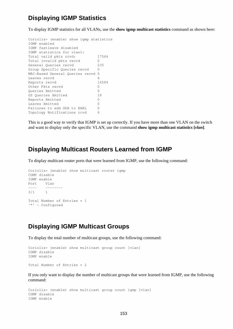
Displaying IGMP Statistics
To display IGMP statistics for all VLANs, use the show igmp multicast statistics command as shown here:
Coriolis> (enable) show igmp statisticsIGMP enabledIGMP fastleave disabledIGMP statistics for vlan1:Total valid pkts rcvd: 17564Total invalid pkts recvd 0General Queries recvd 235Group Specific Queries recvd 0MAC−Based General Queries recvd 0Leaves recvd 4Reports recvd 14584Other Pkts recvd 0Queries Xmitted 0GS Queries Xmitted 18Reports Xmitted 0Leaves Xmitted 0Failures to add GDA to EARL 0Topology Notifications rcvd 6
This is a good way to verify that IGMP is set up correctly. If you have more than one VLAN on the switchand want to display only the specific VLAN, use the command show igmp multicast statistics [vlan].
Displaying Multicast Routers Learned from IGMP
To display multicast router ports that were learned from IGMP, use the following command:
Coriolis> (enable) show multicast router igmpCGMP disableIGMP enablePort Vlan———— ————————3/1 1
Total Number of Entries = 1‘*’ − Configured
Displaying IGMP Multicast Groups
To display the total number of multicast groups, use the following command:
Coriolis> (enable) show multicast group count [vlan]CGMP disableIGMP enable
Total Number of Entries = 2
If you only want to display the number of multicast groups that were learned from IGMP, use the followingcommand:
Coriolis> (enable) show multicast group count igmp [vlan]CGMP disableIGMP enable
153

Total Number of Entries = 1
To get more detail about the multicast groups, use this command:
Coriolis> (enable) show multicast group [vlan]CGMP disableIGMP enable
VLAN Dest MAC/Route Des Destination Ports or VCs / [Protocol Type]———— —————————————————— ——————————————————————————————————————————1 01−88−75−88−08−57* 2/1−121 11−87−96−54−22−11* 2/1−12
Total Number of Entries = 2
Again, if you only want to see the entries that were learned from IGMP, you can use the command showmulticast group igmp [vlan].
Configuring CGMP
CGMP is disabled by default. Use the following command to enable CGMP:
Coriolis> (enable) set cgmp enableCGMP support for IP multicast enabled.
Disabling CGMP
To disable CGMP, use the following command:
Coriolis> (enable) set cgmp disableCGMP support for IP multicast disabled.
Enabling CGMP Fast−Leave Processing
To enable CGMP fast−leave processing, enter the following command:
Coriolis> (enable) set cgmp leave enableCGMP leave processing enabled.
Disabling CGMP Fast−Leave Processing
To disable CGMP fast−leave processing, enter the following command:
Coriolis> (enable) set cgmp leave disableCGMP leave processing disabled.
Displaying CGMP Statistics
To display CGMP statistics, use the following command:
Coriolis> (enable) show cgmp statCGMP enabled.
CGMP statistics for vlan 1:valid rx pkts received 12548invalid rx pkts received 0valid cgmp joins received 12865valid cgmp leaves received 147
154

valid igmp leaves received 0valid igmp queries received 568igmp gs queries transmitted 0igmp leaves transmitted 0failures to add GDA to EARL 0topology notifications received 10number of CGMP packets dropped 2456875
Configuring RGMP on the Switch
RGMP is disabled by default. Use the following command to enable RGMP globally:
Coriolis> (enable) set rgmp enableRGMP enabled.
Disabling RGMP on the Switch
To disable RGMP, use the following command:
Coriolis> (enable) set rgmp disableRGMP disabled.
Configuring RGMP on the Router
RGMP must be enabled on each interface that has the appropriate topology. Use this command:
Router(config)# vlan−interface 3Router(config−if)# ip rgmp
Disabling RGMP on the Router
To disable RGMP, use the following command:
Router(config)# vlan−interface 3Router(config−if)# no ip rgmp
Note Here are some related commands that you can try on the router:debug ip rgmp [group_name | group_address]show ip rgmp interface [interface_unit_name]show ip rgmp groups [group_name | group_address]
Displaying RGMP Groups
To display all the multicast groups that were joined by RGMP−capable routers, use the following command:
Coriolis> (enable) show rgmp groupVlanDest MAC/Route DesRGMP Joined Router Ports————————————————————————————————————————————————201−00−5e−46−85−111/1,2/14101−00−5e−14−11−285/1Total Number of Entries = 2‘*’ − Configured
155

To display the total number of RGMP groups, use the following command:
Coriolis> (enable) show rgmp group count [vlan]Total Number of Entries = 2
Displaying RGMP−Capable Router Ports
To display the ports to which RGMP routers are connected, use the following command:
Coriolis> (enable) show multicast router rgmpPortVlan—————————2/1 +12/16 +2
Total Number of Entries = 2‘*’ − Configured
Displaying RGMP VLAN Statistics
To display RGMP statistics, use the following command:
Coriolis> (enable) show rgmp statistics 1RGMP enabledRGMP statistics for vlan <1>:Receive:Valid pkts:10Hellos:5Joins:3Leaves:2Byes:0Discarded:0Transmit:Total Pkts:10Failures:0Hellos:10Joins:Leaves:0Byes:0
You can reset the statistics with the command clear rgmp statistics.
Configuring GMRP
To enable GMRP globally, use the following command:
Coriolis> (enable) set gmrp enableGMRP enabled.
156

Disabling GMRP
To disable GMRP globally, use the following command:
Coriolis> (enable) set gmrp disableGMRP disabled.
Enabling GMRP on Individual Ports
You can enable GMRP on a per−port basis using this command:
Coriolis> (enable) set port gmrp enable 2/1−12GMRP enabled on ports 2/1−12.
But don’t be fooled—the switch will let you configure GMRP on a per−port basis, but it will not work unlessyou enable it globally.
Disabling GMRP on Individual Ports
To disable GMRP on each port, use the following command:
Coriolis> (enable) set port gmrp disable 2/1−12GMRP disabled on ports 2/1−12.
Enabling GMRP Forward−All
When GMRP forward−all is enabled, a copy of all multicast traffic is forwarded to that port. You may want touse this feature when a probe or network analyzer is connected to a port. Cisco’s documentation recommendsthat you enable forward−all on any port that is connected to a router. Use this command to enableforward−all:
Coriolis> (enable) set gmrp fwdall enable 2/1GMRP Forward All groups option enabled on port 2/1.
Disabling GMRP Forward−All
To disable GMRP forward−all on a port, use the following command:
Coriolis> (enable) set gmrp fwdall disable 2/1GMRP Forward All groups option disabled on port 2/1.
Configuring GMRP Registration
GMRP registration has three modes:
Normal mode—Allows dynamic GMRP multicast registration and de−registration on the port.• Fixed mode—Registers all multicast group on all ports to this single port and ignores any subsequentregistration and de−registration on other ports. To de−register any multicast group, you must firstreturn the port to Normal mode.
•
Forbidden mode—Un−registers all GMRP multicasts and will not accept any GMRP multicastregistration on that port.
•
To configure Normal mode, use the following command:
Coriolis> (enable) set gmrp registration normal 2/1GMRP Registration is set normal on port 2/1.
157

To configure Fixed mode, use the following command:
Coriolis> (enable) set gmrp registration fixed 2/1GMRP Registration is set fixed on port 2/1.
To configure Forbidden mode, use the following command:
Coriolis> (enable) set gmrp registration forbidden 2/1GMRP Registration is set forbidden on port 2/1.
Displaying the GMRP Configuration
To display the GMRP configuration setting on the switch, use the following command:
Coriolis> (enable) show gmrp configurationGlobal GMRP Configuration:GMRP Feature is currently enabled on this switch.GMRP Timers (milliseconds):Join = 200Leave = 600LeaveAll = 10000GMRP−Status Registration ForwallAll Port(s)——————————— ———————————— —————————— ————————————————Enabled Normal Disabled 1/1−12 2/1−11,2/13−48Enabled Forbidden Disabled 2/12
Setting GMRP Timers
If you have many multicast groups, you can change the GMRP timer value to improve performance. Theleave timer value must be equal to or greater than three times the join timer value. The leaveall timer valuemust be greater than the leave timer value.
You must change the timer values in this order: leaveall timer value, leave timer value, and then join timervalue. If you try to set the join timer value before you change the leave timer value, an error message willresult.
Let’s look at the commands to change the timer values:
Coriolis> (enable) set gmrp timer leaveall 8000GMRP/GARP leaveAll timer value is set to 8000 milliseconds.
Coriolis> (enable) set gmrp timer leave 900GMRP/GARP leave timer value is set to 900 milliseconds.
Coriolis> (enable) set gmrp timer join 300 GMRP/GARP join timer value is set to 300 milliseconds.
Displaying GMRP Timers
To display the GMRP timers, use the following command:
Coriolis> (enable) show gmrp timer
Timer Timer Value (milliseconds)———— ——————————————————————————Join 300Leave 900LeaveAll 8000
Tip
158

GMRP and GARP are interchangeable for the set and show commands. GMRP is considered an alias ofGARP.
Configuring Bandwidth−Based Suppression
Bandwidth−based suppression is a hardware−based suppression method. The threshold is set as a percentageof the port’s bandwidth. When the multicast/broadcast traffic exceeds the threshold within a one secondperiod, the switch stops forwarding multicast/broadcast traffic. Unicast traffic will still be forwarded. Use thefollowing command to configure bandwidth−based suppression:
Coriolis> (enable) set port broadcast 2/12 75%Port(s) 2/12 broadcast traffic limited to 75%.
Configuring Packet−Based Suppression
Packet−based suppression is a software−based suppression method. The threshold is set as a number ofpackets traveling through the port. When the multicast/broadcast traffic exceeds the threshold within aone−second period, the switch stops all incoming traffic for the remainder of the period. Use the followingcommand to configure packet−based suppression:
Coriolis> (enable) set port broadcast 2/12 500Port(s) 2/12 broadcast traffic limited to 500 packets/second.
Disabling Multicast Suppression
Use the following command to disable both bandwidth−based and packet−based suppression:
Coriolis> (enable) clear port broadcast 2/12Port 2/12 broadcast traffic unlimited.
Tip Bandwidth−based suppression is preferable to packet−based suppression. Packet sizes vary, and it isdifficult to determine the right number of packets to specify for packet−based suppression. For example,you could have 500 small broadcast packets that used only 10 percent of the bandwidth—but apacket−based suppression value of 500 would still shut down the port.
159
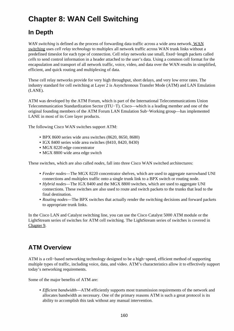
Chapter 8: WAN Cell Switching
In Depth
WAN switching is defined as the process of forwarding data traffic across a wide area network. WANswitching uses cell relay technology to multiplex all network traffic across WAN trunk links without apredefined timeslot for each type of connection. Cell relay networks use small, fixed−length packets calledcells to send control information in a header attached to the user’s data. Using a common cell format for theencapsulation and transport of all network traffic, voice, video, and data over the WAN results in simplified,efficient, and quick routing and multiplexing of data.
These cell relay networks provide for very high throughput, short delays, and very low error rates. Theindustry standard for cell switching at Layer 2 is Asynchronous Transfer Mode (ATM) and LAN Emulation(LANE).
ATM was developed by the ATM Forum, which is part of the International Telecommunications UnionTelecommunication Standardization Sector (ITU−T). Cisco—which is a leading member and one of theoriginal founding members of the ATM Forum LAN Emulation Sub−Working group—has implementedLANE in most of its Core layer products.
The following Cisco WAN switches support ATM:
BPX 8600 series wide area switches (8620, 8650, 8680)• IGX 8400 series wide area switches (8410, 8420, 8430)• MGX 8220 edge concentrator• MGX 8800 wide area edge switch•
These switches, which are also called nodes, fall into three Cisco WAN switched architectures:
Feeder nodes—The MGX 8220 concentrator shelves, which are used to aggregate narrowband UNIconnections and multiplex traffic onto a single trunk link to a BPX switch or routing node.
•
Hybrid nodes—The IGX 8400 and the MGX 8800 switches, which are used to aggregate UNIconnections. These switches are also used to route and switch packets to the trunks that lead to thefinal destination.
•
Routing nodes—The BPX switches that actually render the switching decisions and forward packetsto appropriate trunk links.
•
In the Cisco LAN and Catalyst switching line, you can use the Cisco Catalyst 5000 ATM module or theLightStream series of switches for ATM cell switching. The LightStream series of switches is covered inChapter 9.
ATM Overview
ATM is a cell−based networking technology designed to be a high−speed, efficient method of supportingmultiple types of traffic, including voice, data, and video. ATM’s characteristics allow it to effectively supporttoday’s networking requirements.
Some of the major benefits of ATM are:
Efficient bandwidth—ATM efficiently supports most transmission requirements of the network andallocates bandwidth as necessary. One of the primary reasons ATM is such a great protocol is itsability to accomplish this task without any manual intervention.
•
160

Scalability—ATM is highly flexible, accommodating a wide range of traffic types, traffic rates, andcommunications applications.
•
An ATM network includes two types of devices: ATM switches and ATM endpoints. One type of ATMinterface, called a user−network interface (UNI), connects an ATM device to a switch; a second type, called anetwork−to−network interface (NNI), connects an ATM switch to another ATM switch.
ATM has built−in support for Quality of Service (QoS), which is used to guarantee a level of service fornetworks that use ATM. This guarantee includes bandwidth utilization and data throughput. This type ofservice is critical when dealing with newer multimedia technologies.
LANE
LANE is a method used to provide backward compatibility to legacy Ethernet and Token Ring networks.LANE makes an ATM interface look like an Ethernet or Token Ring network interface, so no modifications toexisting network drivers or applications need to be made to support ATM environments. LANE allows ATMnetworks to emulate Media Access Control (MAC) broadcast networks. Before the implementation of LANE,a proprietary emulation device was needed to connect ATM to a LAN topology.
ATM LANE works with a client/server architecture to create an emulated LAN (ELAN). An ELAN is verysimilar to a VLAN, in that it limits local broadcasts and multicast traffic to the ELAN. LANE devices can beeither clients or servers. The LANE Emulation service (LE service) consists of several different components:
LAN Emulation Client (LEC)—Resides in every ATM device and provides a LAN interface to higherlayer protocols.
•
LAN Emulation Server (LES)—The centerpiece of the LANE architecture. A single LES isresponsible for address registry and resolution for an ELAN.
•
Broadcast and Unknown Server (BUS)—The means by which ATM provides broadcasting supportfor an ELAN.
•
LAN Emulation Configuration Server (LECS)—Contains the database of LES/BUS pairs for all theconfigured ELANs.
•
LANE is discussed in much more detail later in this chapter.
ATM—Easy to Learn?
Nothing in ATM makes it easy to comprehend and learn. It defies a lot of what today’s networkadministrators have learned. Telling you that ATM is used as a backbone protocol in the network makes youthink that you do not need to worry about packet−based broadcast LANs trying to communicate withcell−based ATM networks (which will be discussed in the following sections). In this chapter, I discuss howto connect ATM—which is a connection−oriented, point−to−point protocol—to the Layer 2 addresses of thebroadcast domains in the LAN.
ATM is a difficult subject for most people, because they rarely are exposed to it on a day−to−day basis likeEthernet or Token Ring. In today’s networking environment, however, increased emphasis is being put onintegrating data, voice, and video in networks, and ATM is a driving force. No other protocol today hasATM’s ability to ensure timely delivery of packets based on their type. In addition, ATM can be used on bothLANs and WANs on almost any types of media, with speeds that can scale up to gigabits per second.
161

ATM Protocols
The protocols used in ATM have been specifically designed to support high−speed networks at speedsranging up to gigabits per second (Gbps). Other physical LAN topologies, such as Gigabit Ethernet, providehigh−speed networking and work very well in LANs. ATM, on the other hand, can handle network Gbpstraffic in both LAN and WAN environments and could care less about the type of physical media being used.
ATM works on the theory that it is possible to expect upper−layer protocols to use a connectionless service tocommunicate with the lower layers. LANE is used to allow an upper−layer protocol to make connections tolower−layer ATM connection−oriented services. Thus, LANE provides a switching service that is transparentto the 802.x networks.
Traditional methods of transporting data use one of two ways to send data: character−based or frame−based.ATM is a cell−based switching technology that uses both circuit switching and frame switching to movepackets through the network. Let’s take a closer look at ATM’s method of cell−based circuit switching.
ATM Circuit Switching
ATM is an efficient, high−bandwidth switching and multiplexing technology that also utilizes the benefits ofcircuit switching. Circuit switching is the process of using straight−through circuits between two points toensure minimal transmission latency and guarantee equal bandwidth availability. Let’s take a look at the ATMtechnology components used in ATM circuit switching services:
Circuit emulation (CE)—A connection−oriented, constant bit rate ATM transport service. Thisservice handles the heavy−duty, end−to−end timing requirements for the user’s chosen bandwidth andQoS requirements for establishing a connection. This is typically a dedicated line for applicationssuch as video conferencing and multimedia.
•
Frame Relay—A widely used industry standard for WAN traffic that works by switching Data Linklayer data. It uses multiple virtual circuits by implementing High−Level Data Link Control (HDLC)encapsulation between connected devices.
•
Switched Multimegabit Data Services (SMDS)—A high−speed, packet−switched, datagram−basedWAN technology typically offered by telephone companies.
•
Cell relay services (CRS)—The basis for networking protocols, including ATM, SMDS, and IEEE802.6. This networking technology uses small, fixed−length cells that can be switched in hardware atvery high speeds.
•
Frame Relay, SMDS, and CRS are fastpacket transmission technologies used in today’s network. Moststandard ATM platforms can support all three of these fastpacket technologies. Typically, these transmissiontechnologies support two types of network connections:
Permanent virtual circuit (PVC)—A logical physical connection between two communicating ATMpeers. This type of connection remains active (static) between two endpoints regardless of whetherdata is being transmitted over the connection. PVCs are typically used for interconnectivity betweentwo fixed locations, such as a data center or company locations. This type of connection allows thenetwork bandwidth to be predictable and constant.
•
Switched virtual circuit (SVC)—A switched connection that is established by means of a defined andstandardized ATM signaling protocol. Such connections are set up dynamically and are activated onlywhen data must be sent to the other end of the logical link. The connection is made on demand and isthen terminated.
•
ATM Cells
ATM transports network data in fixed−sized units commonly called cells. Each cell is 53 bytes in length andis divided into a 5−byte header and 48 bytes of data. The 53−byte size of the cell, illustrated in Figure 8.1, is acompromise between the voice, data, and video advocates—one side wanted small cells (32 bytes) andanother wanted larger packets (64 bytes). The final decision was to add the defaults (32 + 64 = 96) and divide
162
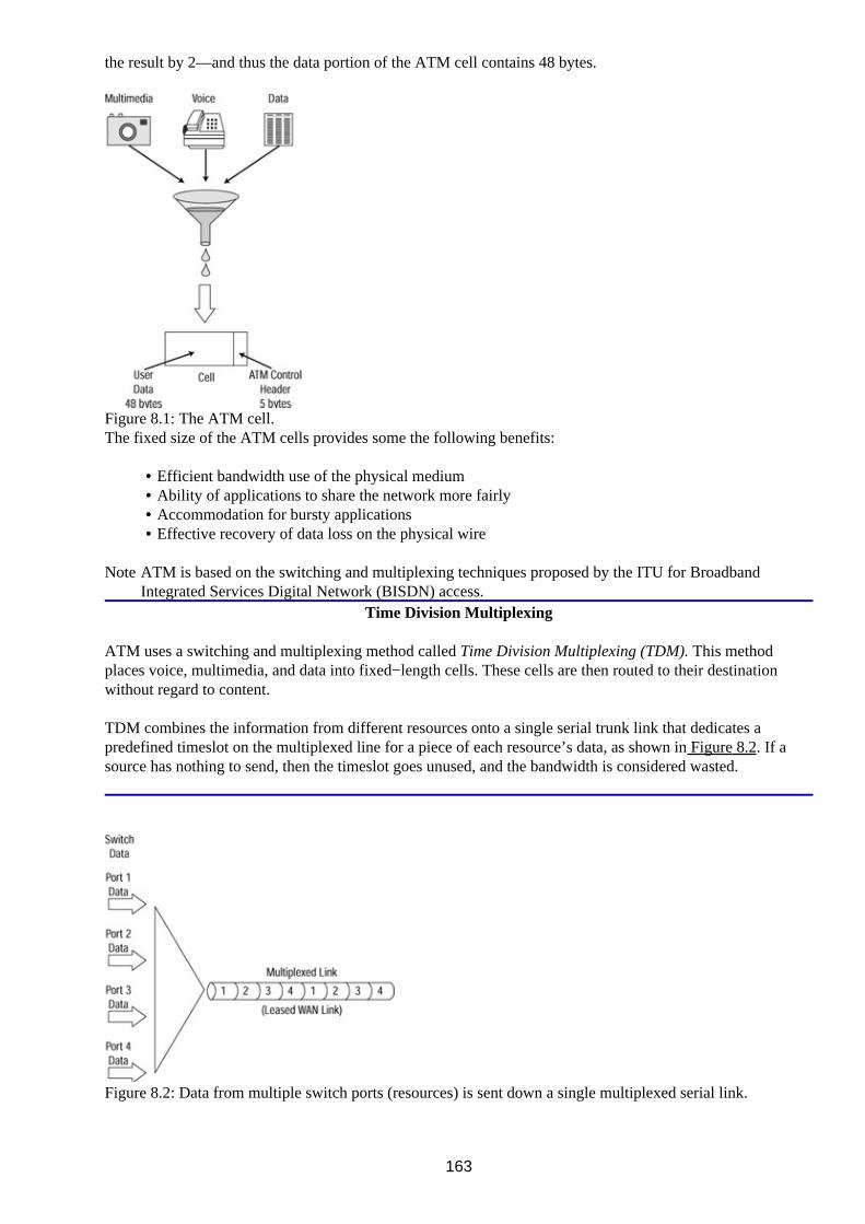
the result by 2—and thus the data portion of the ATM cell contains 48 bytes.
Figure 8.1: The ATM cell.The fixed size of the ATM cells provides some the following benefits:
Efficient bandwidth use of the physical medium• Ability of applications to share the network more fairly• Accommodation for bursty applications• Effective recovery of data loss on the physical wire•
Note ATM is based on the switching and multiplexing techniques proposed by the ITU for BroadbandIntegrated Services Digital Network (BISDN) access.
Time Division Multiplexing
ATM uses a switching and multiplexing method called Time Division Multiplexing (TDM). This methodplaces voice, multimedia, and data into fixed−length cells. These cells are then routed to their destinationwithout regard to content.
TDM combines the information from different resources onto a single serial trunk link that dedicates apredefined timeslot on the multiplexed line for a piece of each resource’s data, as shown in Figure 8.2. If asource has nothing to send, then the timeslot goes unused, and the bandwidth is considered wasted.
Figure 8.2: Data from multiple switch ports (resources) is sent down a single multiplexed serial link.
163

The ATM Cell Header
The ATM cells can be found in one of two formats, depending on whether the endpoints are a UNI or an NNIconnection. The two differ in one way: The NNI header does not contain a Generic Flow Control (GFC) field.The NNI header has a Virtual Path Identifier (VPI) that occupies the entire first 12 bits. A cell header for aUNI cell is shown in Figure 8.3.
Figure 8.3: An ATM UNI cell header.Let’s take a look at the fields in a cell header:
Generic Flow Control (GFC)—An 8−bit field that is used to provide information to identify multiplestations that share a single ATM interface. The GFC is typically not used.
•
Virtual Path Identifier (VPI)—An 8−bit field used with the VCI to identify the next destination of acell as it passes through a series of ATM switches on its way to its destination.
•
Virtual Channel Identifier (VCI)—An 8−bit field used in conjunction with the VPI to identify a cell’snext destination.
•
Payload Type (PT)—A 3−bit field that indicates whether the cell contains user data or control data. Ifthe cell contains user data, the second bit in the user data indicates congestion, and the third bitindicates whether the cell is the last in a series of cells that represent a single AAL5 frame.
•
Congestion Loss Priority (CLP)—A 1−bit field that indicates whether the cell should be discarded ifit encounters extreme congestion as it moves through the network.
•
Header Error Check (HEC)—An 8−bit field that indicates a checksum calculated only on the headeritself.
•
The ATM Switch and ATM Endpoints
ATM networks use one of two types of devices for each end of the network: ATM switches and ATMendpoints. An ATM endpoint is a device that has an ATM network interface adapter, such as a workstation,router, Data Service Unit (DSU), or LAN switch. These devices in turn transmit data to an ATM switch,which is responsible for receiving this data, updating the header information, and then sending the data out theproper interface port to its intended destination.
As mentioned earlier in the chapter, in a UNI, the ATM interface connects an endpoint to a switch. In an NNI,the interface connects two ATM switches together. The UNI and NNI connections can be used to furtherdivide the network into private and public networks. As the name implies, a private network connects theATM endpoint to a private network, whereas a public network connects an ATM endpoint to a public switch(possibly owned by a telephone company or other WAN service provider).
The ATM Reference Model
The ATM standard uses a reference model to describe the functions of the protocol. The ATM ReferenceModel has three layers (which roughly correspond to those in the OSI model) and three management planes.The ATM Physical layer is similar to the Physical layer of the OSI model. The Physical layer controls thetransmission and receipt of bits on the physical medium.
The ATM layer and the ATM Adaptation layer (AAL) are similar to the Data Link layer of the OSI chart. The
164

ATM layer is responsible for establishing connections and passing cells through the ATM network. The ATMAdaptation layer translates the different types of network traffic. Four AALs are defined, but only three areactively in use:
AAL1—Used to transport timing−dependent traffic such as voice• AAL3/4—Used by network service providers in Switched Multimegabit Data Service (SMDS)networks
•
AA5—The primary AAL used for non−SMDS traffic that doesn’t require the pacing AAL1 wouldprovide
•
Figure 8.4 shows the mapping of the ATM Reference Model compared to the OSI Reference Model.
Figure 8.4: The ATM Reference Model layers compared to OSI Reference Model layers.The Physical Layer
The ATM Physical layer controls transmission and receipt of bits on the physical media. This layer also tracksthe ATM cell boundaries and packages cells into the appropriate frame type. This layer is divided into twosublayers: the physical medium dependent (PMD) sublayer and the transmission convergence (TC) sublayer.
The PMD sublayer is responsible for sending and receiving a continuous flow of bits with the timinginformation to synchronize the transmission and reception of data. ATM does not care about the physicalmedia being used, and all widely used physical topologies are capable of supporting ATM cells. Existinghigh−speed topologies capable of supporting ATM cells include Synchronous Optical Network (SONET),DS3/E3, Fiber Distributed Data Interface (FDDI), and unshielded twisted pair (UTP).
The TC sublayer is used to maintain the ATM cell boundaries, verify the validity of data, maintain datasynchronization, create and check header error control to ensure valid data, and put the cells into a format thatthe physical media can use. This sublayer also extracts and inserts ATM cells within either a PlesiochronousDigital Hierarchy (PDH) or a Synchronous Digital Hierarchy (SDH) Time Division Multiplexed (TDM)frame and passes this frame to and from the ATM layer.
The ATM Layer
The ATM layer is responsible for establishing connections, passing cells to and from the AAL, inserting theATM header, and extracting the ATM header. This layer is also responsible for multiplexing anddemultiplexing data through the ATM network. To do this, ATM uses information contained in the header ofeach ATM cell. ATM switches use a VPI and a VCI field inside the ATM cell header to identify the nextnetwork segment a cell needs to transit on its way to its final destination.
A VCI is also known as a virtual channel. It is an identifier for the physical connection between the two endsthat form a logical connection. A VPI is the identifier for a group of VCIs that allows an ATM switch toperform operations on a group of virtual connections (VCs).
165

The ATM Adaptation Layer
The ATM Adaptation Layer (AAL) provides the translation between the larger service data units of the upperlayers of the OSI Reference Model and ATM cells. It works by receiving packets from the upper−levelprotocols and breaking them into 48−byte segments to be dumped into the payload of an ATM cell. The AALhas two sublayers: segmentation and reassembly (SAR) and the convergence sublayer (CS). The CS hasfurther sublayers: the common part (CP) and the service specific (SS). Like protocols specified in the OSIReference Model, Protocol Data Units (PDUs) are used to pass information between these layers.
The AAL translates between the different types of network traffic—such as video streams, data packets, andvoice packets—of upper−layer processes and ATM cells. In other words, the AAL receives packets fromupper−level protocols and breaks them into the 48−byte segments that form the payload field of an ATM cell.Several types of AAL standards are defined for this layer. Which AAL you use will largely depend on thetype of traffic and what you are trying to do with the traffic. The characteristics of each AAL are as follows:
AAL1 (Class A)—This layer is a connection−oriented service that provides end−to−end timingprovisions. It maintains a constant data transfer rate, which is used for transporting telephone trafficand uncompressed video traffic. This is known as a constant bit rate (CBR) service. It is appropriateto use AAL1 to transport voice and video traffic or another type of timing−sensitive data.
•
AAL2 (Class B)—This layer is reserved for data traffic that requires variable bit rates (VBR) andtiming sensitivity, such as multimedia. It multiplexes short packets from multiple sources into a singlecell with end−to−end timing and connection orientation.
•
AAL3/4 (Class C)—This layer was designed for network service providers; it closely aligns withSMDS. This layer uses no VBR and has no timing requirements. It supports both connection−orientedand connectionless data for WAN links using Frame Relay or X.25. This layer is perfectly suited foruse in environments that need to send or receive large files. AAL3 is identical to AAL4, with theexception that the AAL3 layer is connection−oriented only, whereas AAL4 is bothconnection−oriented and connectionless.
•
AAL5 (Class D)—This layer is the primary AAL used to transfer non−SMDS data. It supports bothconnection−oriented and connectionless data. This layer is used for such applications as classical IP(CLIP) over ATM and LANE. Catalyst switches use this layer to provide LANE services for ATM.
•
ATM networks provide the transport method for several different independent emulated LANs. When adevice is attached to one of these emulated LANs, its physical location no longer matters to the administratoror implementation. This process allows you to connect several LANs in different locations with switches tocreate one large emulated LAN. This arrangement can make a big difference, because attached devices cannow be moved easily between emulated LANs. Thus, an engineering group can belong to one ELAN and adesign group can belong to another ELAN, without the groups ever residing in the same location.
LANE also provides translation between multiple−media environments, allowing data sharing. Thus, TokenRing or FDDI networks can share data with Ethernet networks as if they were part of the same network.
Specifying ATM Connections
ATM networks manage traffic by establishing and configuring each connection. When establishing theconnection, the connection type and the resources required to support the connection are specified as a class ofservice. This class is used to provide users with a guaranteed QoS.
The classes of service for QoS are defined by the ATM Forum and are as follows:
Available bit rate (ABR)—Supports variable−rate data transmissions without preserving any timingrelationships between the source and destination nodes. This connection type provides for a best effortservice above a specified minimum cell rate (MCR).
•
Constant bit rate (CBR)—Typically used to carry constant rate traffic and represented by fixedtiming. CBR is typically used for circuit emulation, uncompressed voice, and multimedia data traffic.
•
166

Variable bit rate−real time (VBR−RT)—Typically used for connections that carry VBR traffic inwhich a fixed timing relationship exists between either VBR video or voice compression.
•
Variable bit rate−non real time (VBR−NRT)—Used to carry VBR traffic in which no timingrelationship exists for data traffic where a guarantee of bandwidth or latency is needed. This type ofconnection is used in Frame Relay where the committed information rate (CIR) of the Frame Relayconnection is mapped into a bandwidth guarantee within the ATM network.
•
Unspecified bit rate−real time (UBR−RT)—Does not offer any service guarantees whatsoever. Thistype of connection is typically for the bursty or unpredictable traffic patterns from LAN protocolsserved by ATM routers.
•
ATM Addressing
ATM devices must have unique ATM addresses in order to connect to other ATM devices. The device at theother end of your circuit must know your address. ATM uses both private and public types of addresses.Because the ATM standard has adopted the subnetwork model of addressing, the ATM layer is responsible formapping Network layer addresses to the ATM addresses.
Currently, two types of ATM addressing plans are used. The ATM UNI address format defined by ITU−Tuses telephone−type E.164 addresses. This format is used to connect an endpoint to a telephone carrier’snetwork. One drawback to this type of address is that E.164 addresses are available only from large telephonecarriers, which prevents the addresses from being assigned to competitors and private businesses.
The ISO has defined a second address type that uses a Network Service Access Point (NSAP) format. Thisformat is used to connect an ATM endpoint to a private network. The ATM Forum has now used this methodto incorporate the E.164 address of the public networks into the address of customers using NSAP addresses.The ATM Forum is also working on a method for the phone carriers to use NSAP−based addressing on theirnetworks. Let’s take a look at the components of an NSAP address, as shown in Figure 8.5:
Figure 8.5: The format of an ATM NSAP address.
Authority and format identifier (AFI)—Used to indicate which standard is being used for the ATMaddress. An AFI of 47 indicates a British Standards Institute address (used by Cisco on all its ATMdevices); an AFI of 39 indicates an ISO address and an E.164 address.
•
Initial domain identifier (IDI)—Indicates the address allocation and administrative authority.• Domain specific part (DSP)—Contains the actual routing information.• End−system identifier (ESI)—Places the end system’s MAC address in the frame.• NSAP selector field (SEL)—Identifies the LANE components.•
Local Area Network Emulation (LANE)
In a LAN environment, broadcast support is an inherent part of the networking technology. Legacy networkshave native broadcast support to perform address mapping resolution. In contrast, ATM networks areNon−Broadcast Multiple Access (NBMA) networks with no such support. The LANE standard was createdby the ATM Forum in 1994 to provide connectivity for ATM networks to legacy Ethernet and Token−Ringnetworks.
LANE provides these broadcast services by making an ATM interface look like an Ethernet or Token Ringinterface. LANE gives ATM devices MAC addresses, just like Ethernet or Token Ring devices. Because theATM interfaces can use the same frame format as legacy devices, LAN−based applications can run without
167

changing the application itself or Layer 3 drivers.
This approach allows backward compatibility with existing LANs, broadcast support, and connectionlessdelivery. LANE has some drawbacks, however: It prevents the use of ATM−specific benefits such as QoS anddoesn’t have the ability to provide flexible bandwidth allocations.
LANE is the primary component that provides connectivity between ATM devices and the devices residing onthe Layer 2 LAN. This connectivity extends to devices attached to ATM stations and devices attached to LANdevices spanning the ATM network. This connectivity between ATM devices and other LAN devices is donethrough ELANs.
What Are ELANs?
ELANs are just like VLANs—one of their functions is to create independent broadcast domains in ATM, thesame way that VLANs do in Ethernet and Token Ring networks. ELAN workstations are independent of thephysical location, and like VLANs, ELANs must be connected to a Layer 3 device in order to communicatewith members of another ELAN.
The Data Link layer’s MAC sublayer allows ELANs to use the Microsoft or Novell upper−level NDIS/ODIdriver interfaces. This method allows ELANs to transmit Layer 3 protocols such as TCP/IP, IPX, andAppleTalk.
LANE is a standardized conversion process that allows a connectionless environment in a LAN to connect toa connection−oriented ATM environment. LANE fragments an incoming Layer 3 into a 48−byte payload andplaces a 5−byte ATM−specific identification header on the front of the packet, yielding a 53−byte cell. It thenremoves the checksum from the cell and forwards the cell through the ATM network. When the cell hastraveled the ATM network, the ATM information is removed and the cell fragments are reassembled andreturned to the LAN environment as a packet.
The LANE 1.0 standard can be summed up as a software interface for the Layer 3 protocol environment thatencapsulates user data for either Ethernet or Token Ring packets. LANE isn’t actually the media accessmethod for this conversion process—LANE uses three servers, which clients access over the ATMconnections. The LANE servers provide address registration and resolution functions, including collectingaddress and route descriptor types based on the LANE standard. Let’s take a look at the LANE components.
Note FDDI can be used with LANE 1.0; however, it is not accurately defined like Ethernet and Token Ringprotocols. ATM uses translational bridging techniques to map FDDI packets into either Ethernet orToken Ring.
LANE Components
LANE uses several components to provide LAN−based network connectivity. The interaction of thesecomponents allows address registration, address caching, and searchable databases. LANE uses the followingcomponents:
LAN Emulation Client (LEC)—Emulates a LAN interface to higher−layer protocols and applicationsof the OSI Reference Model.
•
LAN Emulation Server (LES)—Provides a database of LANE services, resolves addresses, managesstations that make up an ELAN, and provides registration services to LANE clients for the emulatedLAN.
•
LAN Emulation Configuration Server (LECS)—Uses a database to track device memberships in eachELAN.
•
168

Broadcast and Unknown Server (BUS)—Sends broadcasts, sequences cells, controls unicast flooding,and distributes multicast packets.
•
Warning Notice that although LEC and LECS sound the same, they are completely different terms andcomponents in LANE.
LAN Emulation Client (LEC)
The LEC resides in every ATM end system. It provides services to emulate the Data Link layer interface thatallows communication of all higher−level protocols and applications to occur. It provides both ATM−attacheddevices and ATM−capable Token Ring, Ethernet, and legacy LAN topologies the ability to coexist within anATM emulated LAN and WAN environment.
The LEC is the component responsible for passing traffic between separate VLANs on the Catalyst switchesand between ELANs on the ATM switch. You can configure multiple LECs for one or more ELANs on theATM modules. Prior to configuring a LEC on an ATM module, a VLAN must be configured on the switch,and the LES/BUS or an ELAN must be configured on one or more ATM module subinterfaces.
The LEC forwards data to other LANE components in the ELAN and performs control functions. Each LECis a member of only one ELAN. In many instances, an Ethernet switch may have multiple LECs for eachELAN. Examples of LEC implementations include servers, routers, switches, or other network hosts. TheLEC has the following functions:
Resolves MAC addresses• Transfers data• Performs address caching• Interfaces with other LANE components• Provides interface driver support•
LAN Emulation Server (LES)
The LES for an ELAN is the central piece of LANE. It gives the LECs the information they need to establishATM connections to other LECs in their ELAN. A single LES is responsible for address registry andresolution for an ELAN. When a LEC joins an ELAN, it forms a connection with the LES. The LEC registersits MAC and ATM addresses with the LES. The LES has the following functions:
Supports LECs• Registers addresses from LECs• Resolves addresses from LECs• Interfaces to the LEC, LECS, and BUS•
The LES performs traffic control for all LECs connecting to an ELAN. This component provides the addressresolution, registration, broadcast, and unknown server information that guides communication among LECs.When configuring each LEC, the LEC must request a connection from the LES. The request informationcontains the ATM address of the LEC, a LAN identifier, and an optional MAC address. This component alsoperforms verification of each LEC during the initial connection with the server, checking to make sure thateach LEC has permission to join the requested ELAN.
Address registration is also a function of the LES. It must maintain a database to aid in resolving addresses.This registration occurs after the LEC joins an ELAN. Each LEC provides the LES with one registeredaddress with a join request, and no separate registrations are required.
The LES with the ATM address database responds to all address resolution queries and attempts to locatepartnering LECs. The LES responds with the ATM addresses for the targeted ELANs. If no address can befound, the LES attempts to forward the request to other LECs on other ELANs.
169

The ultimate goal of the LES is to arrange and control connections with a LEC. This connection is commonlyknown as a control direct ATM virtual channel connection (VCC). After this connection is established, it willhandle address resolution and registration responses.
Note The LES establishes communication with the LECS and provides verification information forLECs attempting to join. The LES does not maintain a constant connection with the BUS.The LES only provides each LEC with the ATM address of the BUS for forwarding.
The LANE servers provide the address registration and resolution functions. These functions includecollecting address and route descriptor types based on the LANE standard. Let’s take a look at the addressresolution process, which is shown in Figure 8.6 and outlined as follows:
Figure 8.6: The LES address resolution process.
A workstation connects to a router or ATM switch and performs a physical outbound packettransmission. This example uses the Address Resolution Protocol (ARP) query to try to locate adevice on a remote segment.
Note The local router is typically the ATM LEC and provides the circuit for the initial ATM addressmapping.
1.
The LEC takes an Ethernet frame and assigns an immediate LEC link, which is used to obtain theATM address identifier needed to establish an ATM connection. If this process is not successful, theLEC must locate a LES.
2.
The LES circuit holds the main ATM network address table and returns with the VCI assignment.3.
LAN Emulation Configuration Server (LECS)
The LECS provides key services such as registration for Integrated Local Management Interface (ILMI) andconfiguration support for the LES addresses for the corresponding emulated LAN identifiers.
The LECS contains a database of ATM addresses for the LES and BUS pairs for known ELANs. The LECconsults the LECS to determine the LES’s ATM address when it first joins an ELAN.
Note At least one LECS is required per ATM LANE switch cloud.
The LECS has the following functions:
Registers the LECS ATM addresses for known ELANs• Supplies LECs with LESs’ ATM addresses• Provides interfaces to the LEC and the LES•
The registration process of the LECS ATM address uses the ILMI functions to connect to the ATM network;this situation usually includes an ATM switch. Support for configurations from the LECS ensures that thecorrect LES address is supplied to the LEC.
170

Broadcast and Unknown Server (BUS)
The BUS provides broadcasting support for an ELAN. The BUS distributes multicast data, sends ordistributes unicast data, and connects the other LANE components. When the destination address of anEthernet or Token Ring frame contains a local broadcast or a multicast address, the LEC forwards the trafficto the BUS, which forwards it to all the other LECs in the ELAN. At least one combined LES and BUS isrequired per ELAN. The BUS has the following functions:
Distributes multicast data• Sends or distributes unicast data• Interfaces to LEC and LES•
The LES is the component responsible for resolving MAC addresses to ATM addresses, and the BUS is thecomponent responsible for servicing multicast, Ethernet, and Token Ring broadcasts. The Cisco LANEimplementation calls for the LES and the BUS to be configured in the same end−station.
ATM Module Subinterfaces
In order to configure ATM components on an ATM LANE module for the Catalyst 5000 or 6000 family ofswitches, you need to use subinterfaces. Depending on the level of traffic you expect on your network, youmay want to place different LES/BUS components throughout the framework of your network. To configure aLES or BUS on the ATM module, you need to complete the following tasks:
Enter Interface Configuration mode.1. Specify the subinterface for the ELAN.2. Specify the type of link: Ethernet or Token Ring.3. Enable the LES and BUS on the ELAN.4. Repeat this process for each LES/BUS.5.
The BUS must be used to sequence and distribute broadcast data to all the LECs. However, sending a largevolume of broadcast data to all the LECs can severely impact the overall performance of the network. For thisreason, it may be necessary for the BUS to place restrictions on the LANE components to control themaximum throughput rate for each device. The BUS’s primary function is to provide broadcast managementsupport for LANs. The BUS must supply the following services:
Distribute unicast and multicast data to all the LECs in the network• Connect interfaces to the ELAN•
Distribution of unicast and multicast data includes the transmission of data to the LECs in the network.Whenever possible, the LEC will establish a direct connection to another LEC. If this isn’t possible, then datathe BUS receives is broadcast to each LEC on the ELAN. This option can be enabled and disabled, and youshould carefully consider whether you need this option, because it can eat up costly bandwidth.
Note When interfacing to ELANs, the BUS establishes a bi−directional connection that allows forwarding ofmulticast and unicast frames with unknown destinations.
LEC Queries
LECs send queries for configuration information to receive the LES address. The LECS then assigns thecorrect LES address for each LEC. The LES also has the ability to establish a connection with the LECS.
A reply to a query can be as simple as providing a single LES address or it can provide more information,such as:
171

The default ELAN name• The LEC address and corresponding LES• The ELAN name and corresponding LES• The ATM address prefix and corresponding LES• The ELAN type and corresponding LES• The ELAN name• The corresponding ATM address of a LANE server• A LANE client MAC address• A client MAC address with the corresponding ELAN name• The LANE client ATM template•
ATM Addresses
ATM addresses are 40−digit addresses that use the ILMI protocol to provide the ATM prefix address of theswitch for the LECs. This process configures the initial 26 (hexadecimal) digits of the ATM address, whichare identical for each LEC. The next 12 (hexadecimal) digits of the ATM address are known as the ESI. Thereis also a two−digit SEL field. To provide this part of the ATM address, Cisco provides a pool of 16 MACaddresses for each ATM module, although only 4 are used. The following assignments pertain to the LANEcomponents:
The prefix fields are the same for all LANE components and indicate the identity of the ATM switch.• All LECSs are assigned an ESI field value from the first pool of MAC addresses assigned to theinterface.
•
All LESs are assigned an ESI field value from the second pool of MAC addresses.• The BUS is assigned an ESI value from the third pool of MAC addresses.• The LECS is assigned an ESI value from the fourth pool of MAC addresses.•
Integrated Local Management Interface (ILMI)
The ILMI protocol was defined by the ATM Forum. It aids in initialization and configuration of ATM LECs.ILMI uses the Simple Network Management Protocol (SNMP) to share information between an ATM clientand an ATM switch. It uses a well−known permanent connection to the LECS that has a VPI of 0 and a VCIof 17.
The basic functions of ILMI are to enable the LEC to discover the ATM address of the LECS and to allow theLEC to tear down virtual circuits when they are no longer in use. ILMI allows the ATM switch to share itsATM prefix with the LECs, which lets the LECs share the same initial 13 bytes of their own 20−byte ATMaddress. This scheme makes it easier to route traffic between switches, because the switch only needs to lookat the first 13 bytes to determine which ATM switch has the end−station. ILMI is an extremely popular way toresolve addressing in ATM networks.
LANE Communication
Now that we have looked at the individual components that make up the LANE model, let’s examine thecommunication process. Like X.25 and Frame Relay, LANE components communicate by using SVCs.Several different types of SVCs exist in the ATM LANE implementation; they are called virtual channelconnections or virtual circuit connections (VCCs), depending on the standards documents you refer to. TheseVCCs are as follows:
Unidirectional VCCs• Bidirectional VCCs• Point−to−multipoint control distribute VCCs• Point−to−point configure direct VCCs•
172

In the ATM LANE communications process, when a client wants to join an ELAN, the client must build atable that links ATM addresses to Ethernet MAC addresses. Let’s take a close look at this process:
The LEC first sends a LAN Emulation ARP (LE_ARP) message to the LES that is using apoint−to−point configure direct VCC. This query is made to the ATM switch containing the LECS,using ILMI. The query is a request for the ATM address of the LES for its emulated LAN. The switchcontains a Management Information Base (MIB) variable containing the requested ATM address. TheLEC will attempt to locate the LES using these steps:
Uses ILMI to connect to the LECSa. Checks to see if any locally configured ATM addresses existb. Checks to see if it has received a fixed address defined by the MIB variable using UNIc. Checks to see if this is a well−known permanent virtual circuitd.
1.
The LES forwards the LE_ARP to all clients on the ELAN using a point−to−multipoint controldistribute VCC.
2.
The LECS responds across the established connection with the ATM address and name of the LES forthe LEC’s ELAN. The LEC can establish a connection with the LES based on the configuration datareceived. This connection is a bidirectional point−to−point control direct VCC; it remains openthroughout the remainder of the communications process.
3.
The LES forwards the response using a point−to−multipoint control distribute VCC to the LEC.While the connection is established with the LEC requesting entry to the ELAN, the LES attempts tomake a bidirectional connection to the LECS to request verification that the requesting LEC mayenter the ELAN. After this verification is completed, the server configuration that was received in thefirst connection is verified against the LECS database; if authentication is approved, the client gainsmembership in the ELAN.
4.
The LEC creates another packet with the correct ATM address for the LES and establishes a controldirect VCC to make the connection. The LEC sends out a LE_JOIN_REQUEST to the LEScontaining the LEC ATM address as well as the MAC address, in order to register with the ELAN.
5.
The LES checks with the LECS to verify the LEC. The LES receives the data, creates a new entry inthe cache for the LEC, and sends a LE_JOIN_RESPONSE back to the LEC.
6.
The LES replies to the LEC using the existing configure direct VCC. This process is completed byeither allowing or denying membership in the ELAN. If the LES rejects the LEC’s request, thesession is terminated.
7.
If the LES connection is allowed, the LEC is added to the point−to−multipoint control distribute VCCconnection. The LEC is granted a connection using the point−to−point control VCC to thecorresponding LEC, and the higher−level protocols take over.
8.
If permission is granted by the LES, the LEC must determine the ATM address for the BUS in orderto become a member of the broadcast group.
9.
The LEC must locate the BUS, so it sends an LE_ARP_REQUEST packet containing the MACaddress 0xFFFFFFFF. This packet is sent down the control direct VCC to the LES, which understandsthe request for the BUS. The LES responds with the ATM address for the BUS.
10.
When the BUS is located, the LEC can become a member of the ELAN.11.
LE Messages
An LE_ARP message is used to allow a LEC to indicate that a particular MAC address resides on a local nodeon the local network. This message can then be redistributed to all other LECs in the ELAN to allow thoseLECs to update their address cache.
Once a client has joined an ELAN and built an address cache based on the LE_ARP messages received, theclient can establish a VCC to the desired destina−tion and transmit packets to the ATM address mapped to thephysical MAC address using a bidirectional point−to−point data direct VCC. Let’s take a look at four types ofpackets:
173

LE_ARP_REQUEST—Contains the broadcast MAC address 0xFFFFFFFF. This packet is sent on acontrol direct VCC to the LES to query for the ATM address of the BUS.
•
LE_ARP_RESPONSE—Sent in response to an LE_ARP_REQUEST; it contains the ATM address ofthe BUS.
•
LE_JOIN_RESPONSE—Contains the LANE client identifier (LECID) that is a unique identifier foreach client. This ID is used to filter return broadcasts from the BUS.
•
LE_JOIN_REQUEST—Allows the LEC to register its own MAC and ATM addresses with the LES aswell as any other MAC addresses for which it is proxying. This information is maintained to makesure that no two LECs will register the same MAC or ATM address.
•
Joining and Registering with the LES
After a LEC joins the LES, the LEC uses its own ATM and MAC addresses. The following process showshow this is done:
After the LEC obtains the LES address, the LEC clears the connection to the LECS to set up acontrol−direct VCC to the LES. It then sends an LE_JOIN_REQUEST on that VCC.
1.
When the LES receives the LE_JOIN_REQUEST, the LES checks with the LECS with its openconnection, verifies the request, and confirms the client’s membership.
2.
If this verification is successful, the LES adds the LEC as a branch in its ATM point−to−multipointcontrol−distribute VCC.
3.
The LES issues the LEC a successful LE_JOIN_RESPONSE that contains a unique LECID.4.
Note The LECID is used by the LEC to filter its own broadcasts from the BUS.When this process is complete, LANE will have created an ATM forwarding path for unicast traffic betweenthe LECs. This forwarding path will enable you to move data across the ATM network.
LANE Configuration Guidelines
When setting up LANE components, you should consider the following list:
The LANE subsystem supports as many as 16 LECS addresses.• The LECS must always be assigned to the major interface.• Two separate ELANs cannot be configured on the same subinterface.• LES/BUSs for different ELANs cannot be configured on the same subinterface.• Each ELAN can define an unlimited number of LES/BUSs.• LECSs come up as masters automatically until a higher−level LECS takes priority.• If multiple LES/BUS pairs are configured for an ELAN, the priority of a pair is determined by theorder in which it was entered in the LECS database. When a higher−priority LES/BUS pair comesonline, it takes over the functions of the current LES/BUS on the ELAN.
•
It may take up to one minute for changes made to the list of LECS addresses to propagate through thenetwork. However, changes made to the configuration database for LES/BUS addresses take placealmost immediately.
•
The ATM Forum−defined well−known LECS address is used if no LECS is operational on an ELAN.•
Note The operating LECSs must use the same configuration database. An identical database can becreated by configuring a LECS database on one device and then copying the database to otherdevices by using the config net command.
How LANE Works
Earlier, I discussed how the different LANE components interact with each other to support the LANemulation services. A LEC goes through three stages to join an ELAN:
Initialization and configuration• Joining and registering with the LES• Finding and joining the BUS•
174

Let’s step through the process. Suppose that you were working on an ELAN and you wanted to access a filestored on a server that was located on a physically separate LAN:
You send the file request. Your LEC determines if it knows the ATM address of its LES.1. If your LEC does not know this address, the client queries the LECS and asks for the ATM address ofthe LES.
2.
After your LEC receives the correct address, it queries the LES for the ATM address of the LESwhere the file is located. If the LES knows this address, it sends the address to your LEC.
3.
If the LES does not know this address, it queries the LANE BUS. The LANE BUS, in turn, asks allthe LECs on the ELAN for their ATM addresses. The LANE BUS returns the correct address to theLES, which returns the address to your LEC.
4.
Your LEC establishes a virtual circuit to the server on which the file is stored. The LEC converts itsEthernet or Token Ring frames into cells and sends these cells over the virtual circuit to the server.
5.
Implementing LANE
LANE is supported on many of the products offered by Cisco, including all Cisco switches from the Catalyst1900 series through the 12000 series, the Cisco LightStream switches, and the 8000 series of WAN switches.Routers such as the Cisco 4000, 4500, 7000, and 7500 can support LANE, as well.
If you’re designing an ATM LANE network, you need to examine each switch’s level of performance andfunctionality. Doing so allows you to determine which switching product is needed at each point in thenetwork. Cisco has created four product lines for specific network types. Each product provides a certain levelof performance and functionality. Cisco provides ATM devices that fit well in all sizes of ATMimplementations, from the smallest to the largest. These four product lines are as follows:
Workgroup switches—The smallest switches, typically found in the Access layer of the network.Workgroup switches begin with the 1900 series switches and includes the Cisco Catalyst 5000. Mostworkgroup switches are located in the wiring closet closest to the end user. These switches are usuallyEthernet based for the local LAN environment and provide an ATM uplink to a campus switch.
•
Campus switches—Typically implemented to relieve the congested nature of the network and toeliminate bandwidth problems across the existing backbone. These switches include the LightStreamfamily of ATM switches. Campus switches support a wide variety of interfaces, including those thathave connections to backbone and to the WAN.
•
Enterprise switches—The next level of ATM switches. These switches allow multilevel campus ATMswitches to be connected for enterprise installations. They also provide the internetworking processesnecessary to route multi−protocol traffic in the network. These switches are not used in the Core layeror backbone; they are used in the enterprise or WAN to meet the needs of high−traffic enterprises oreven public service providers. These are Cisco’s BPX and AXIS switches.
•
Multiservice access switches—Provide a multitude of services for the growing needs of networks.They can provide services to support MANs, WANs, and the campus network.
•
Configuring ATM on the 5000 Switch
The LANE module for the Catalyst 5000 and 5500 series is available with three different types of interfaces:multimode fiber (MMF), single−mode fiber (SMF), and unshielded twisted pair (UTP). On each module, twointerfaces of each type are available—but only one may be used at any time. This arrangement providesredundancy in the event of a hardware failure or the loss of ILMI signaling.
Note When ILMI was first introduced, it was referred to as Interim Local Management Interface because theprotocol was anticipated to have a short life span.
ILMI provides sufficient information for the ATM end−station to find a LECS. The ILMI also provides theATM NSAP prefix information to the end−station. This prefix is configured on a local ATM switch. Theprefix is 13 bytes long; it is then combined with the MAC address (6 bytes) of the end−node (end systemidentifier), and a 1−byte selector, to create a 20−byte ATM address.
175

LANE Modules
The following ATM LANE modules are available for the 5000 family of switches; the list also indicates thecable types that can connect to each. Tables 8.1 and 8.2 show the LED lights and functions on the LANEmodules. These modules provide a connection between multiple ATM networks connecting through the ATMswitch:
Table 8.1: LANE module status LEDs.
Port Color Meaning
Red Diagnostics failure
Orange Module disabled
Green Functioning normallyTable 8.2: ATM LANE module indicator LEDs.
LED Meaning
TX (Transmit) Port is transmitting a cell
RX (Receive) Port is receiving a cell
Link Active link
ATM LANE Single PHY Module (UTP)—Provides a connection between the 155Mbps ATM network,Category 5 UTP cables, and one RJ−45 connector
•
ATM LANE Single PHY Module (MMF)—Provides a connection between a 155Mbps ATM networkand one multimode SC fiber−optic connector
•
ATM LANE Single PHY Module (SMF)—Provides a connection between a 155Mbps ATM networkand one single−mode, SC fiber−optic connector
•
ATM LANE Dual PHY Module (UTP)—Provides two connections between the ATM network,Category 5 UTP cables, and two RJ−45 connectors
•
ATM LANE Dual PHY Module (MMF)—Provides two connections between an ATM network,multimode fiber−optic cable, and two multimode, SC fiber−optic connectors
•
ATM LANE Dual PHY Module (SMF)—Provides two connections between an ATM network, asingle−mode fiber−optic cable, and two single−mode, SC fiber−optic connectors
•
ATM Dual PHY OC−12 Module (MMF)—Provides two connections between the OC−12 (622Mbps)ATM network, a single−mode fiber−optic cable, and two single−mode, SC fiber−optic connectors
•
ATM Dual PHY DS3 Module—Provides two interfaces for two DS3 (45Mbps) connections betweenan ATM network, 75−ohm RG−59 coaxial cable, and two Bayonet−Neill−Concelman (BNC)twist−lock connectors
•
ATM Dual PHY OC−3 Module (MMF)—Provides two direct connections between an OC−3(155Mbps) ATM network, multimode fiber−optic cable, and two multimode, SC fiber−opticconnectors
•
ATM Dual PHY OC−3 Module (SMF)—Provides two direct connections between an OC−3(155Mbps) ATM network, a single−mode fiber−optic cable, and two single−mode, SC fiber−opticconnectors
•
The single−mode LANE module is better equipped for longer distances. It uses a laser optical source and hasa maximum distance of 10 kilometers. The multimode module uses an LED optical source and has amaximum distance of two kilometers. Both modules have a SAR of 512, meaning that the module cansegment and reassemble up to 512 packets simultaneously.
Network Management on the LANE Module
The LANE modules in the Catalyst 5000 and 5500 series switches are configured by using the standard Ciscocommand−line interface (CLI), which is similar to that of a router. This interface can be accessed through the
176

Supervisor Engine’s console port.
Tip Even though the LANE module is configured through the Supervisor Engine, the Supervisor Enginemaintains no configuration information regarding the LANE module. This information is stored on theLANE module itself.
Segmentation and Reassembly
In a frame−based network such as Ethernet, packets sent on the physical wire require a minimum frame size.Ethernet requires a minimum frame size of 64 bytes; this size is larger than an ATM cell, which is only 53bytes with the header information included.
A process must occur to segment or reassemble the data into the needed minimum size for the physical media.This is the job of segmentation and reassembly (SAR), which is a task performed by the Adaptation layer ofthe ATM Reference Model. SAR is responsible for breaking frames into cells and padding cells to result in alarger payload than the 48 bytes from the cells. This process allows the data in cells to traverse the local LANand meet the minimum frame size requirements.
Unfortunately, SAR is one area in which ATM switches fail to perform up to the standard of the physicalwire’s available bandwidth. As a result, SAR alone on the LANE module may have a problem processingpackets fast enough to keep up with frames or cells arriving and being sent on a 155Mbps OC−3. To resolvethis issue, Cisco installed two LSI ATMizers to provide low−latency and wire−speed performance on theLANE module. Each ATMizer operates by itself—one is used for receiving, and the other transmits cells andframes.
Tip The LANE module is capable of addressing 4,096 virtual circuits; however, the default is 1,024, whichprovides sufficient capability for most installations. To provide for data bursts (associated with LANs andnot WANs), the LANE module SAR is capable of traffic shaping using a single−rate queue.
Connecting in an ATM Network
To provide a basis for troubleshooting, it helps to evaluate proper placement of the LES/BUS and LECScomponents in your network. Most ATM LANE environments use LECS to provide configurationinformation to the end−node. This connection uses a configuration direct VCC to query for a LECS. Thisquery uses three processes to try to locate the LECS, in the following order:
Checks the local LECS for a preconfigured address on the local LEC.1. Checks the ILMI to locate the LECS.2. Uses 47:00:79:00:00:00:00:00:00:00:00:00:00:00:00:A0:3E:00:01:00, which is the LECS’swell−known address. This address is specified by the ATM Forum.
3.
After the end−node has contacted the LECS, the LES sends the end−node the information it needs to continuecontact with the LES. This information includes the operating information for the ELAN. The LES willregister the LEC and permit it to join the ELAN. The communication between the LEC and the LES isestablished with the use of a join command on a bidirectional control direct VCC.
At this point, the LEC is responsible for locating the BUS. This is done through the use of an LE_ARPrequest message. The LES responds to this request with the address of the BUS. The LEC then registers andjoins the BUS.
Now, when a client needs to send data to an unknown resource, the LES and BUS establish directcommunication to provide the address information and answer address queries. The LEC sends an LE_ARPrequest to the LES for the destination station and also sends the initial data cells to the BUS, which willforward the data cells to the destination and all the other stations.
177

After the destination node receives the LE_ARP response from the LES, the destination client responds to thesource with its address information. The source sends a “flush” message to the BUS, which instructs the BUSto stop sending any unsent cells—the source will now establish a direct connection with the destination andsend the remaining data.
Monitoring and Maintaining LANE
The following commands can be used to monitor and maintain your LANE network:
show lane—Displays the complete LANE configuration and status information for the LES/BUSs,LECs, and LECSs
•
show lane server—Displays the global and per−VCC LANE information for all the LANEcomponents
•
show lane bus—Displays the global and virtual circuit LANE information for the BUS configured onany subinterface or ELAN
•
show lane client—Displays the global and virtual circuit LANE information for all LECs configuredon any subinterface or ELAN
•
show lane config—Displays the global and virtual circuit LANE information for the LECSconfigured on any interface
•
show lane database—Displays the LECS database• show lane le−arp—Displays the LAN Emulation ARP table contained on the LECs• show atm vc—Displays the ATM virtual circuit information•
Related solutions: Found on page:
Configuring Virtual Private Tunnels 288
Configuring LANE on a LightStream 1010 295
Accessing the ATM LANE Module
The process of accessing and configuring the ATM LANE module on the Cisco Catalyst 5000 and 6000family of switches is identical. The 5000 and 6000 switches both use the Set/Clear CLI, and the LANEmodule uses a CLI similar to a router.
Use the session command followed by the slot number in which the LANE module resides to access the CLIof the LANE module:
Console> (enable) session 5Trying ATM−5…Connected to ATM−5.Escape character is Ô^]’.
Displaying the Selector Field
The last two digits of an ATM address are known as the selector field. This value is assigned on thesubinterface on which a LANE component resides. The LECS must reside on the primary interface, makingthe selector value a static 00. To determine the default ATM addresses the ATM LANE module has assigned,use the show lane default−atm−addresses command. An example of this command and the related output isas follows:
ATM#show lane default−atm−addressesinterface ATM1/0/0:LANE Client: 47.00817200000000E04BAAA006.00E04BAAA060.**
178

LANE Server: 47.00817200000000E04BAAA006.00E04BAAA061.**LANE Bus: 47.00817200000000E04BAAA006.00E04BAAA062.**LANE Config Server: 47.00817200000000E04BAAA006.00E04BAAA063.00note: ** is the subinterface number byte in hex
Note The asterisks in this example indicate that the addresses are in hexadecimal. The ATM LANE moduledoes not list these addresses with this command.
Configuring the LES/BUS
Follow these steps to configure a LES/BUS for two ELANS—the default ELAN and ELAN2:
Enter Global Configuration mode on the LANE module:
ATM#configure terminalEnter configuration commands, one per line. End with CNTL/Z.
1.
Enter Interface Configuration mode for the ATM0 interface, subinterface 1, and indicate whether thelink is point−to−point or multipoint:
ATM(config)#interface atm0.1 point−to−point
2.
Make this subinterface the Ethernet default LES/BUS and identify the ELAN:
ATM(config−subif)#lane server−bus ethernet ELAN2
Note You cannot configure more than one LES/BUS per subinterface.
3.
Repeat Steps 2 and 3 for each LES/BUS you want to configure on this LANE module.4. Enter Interface Configuration mode for the ATM0 subinterface 2:
ATM(config−subif)#interface atm0.2
5.
Map the LES bus to the Ethernet ELAN named ELAN2:
ATM(config−subif)#lane server−bus ethernet ELAN2ATM(config−subif)#end
6.
Verifying the LES/BUS Configuration
To verify the configuration, issue the following command:
ATM#show lane serverLE Server ATM0.1 ELAN name: default Admin: up State: operationaltype: ethernet Max Frame Size: 1516ATM address: 47.00918100000000E04FACB401.00100DAACC41.01LECS used: 47.007900000000000000000000.00A03E000001.00 NOT yet connected
LE Server ATM0.2 ELAN name: TEST_ELAN Admin: up State: operationaltype: ethernet Max Frame Size: 1516ATM address: 47.00918100000000E04FACB401.00100DAACC41.02LECS used: 47.007900000000000000000000.00A03E000001.00 NOT yet connected
Configuring a LEC for an ELAN
Follow these steps to configure two LECs for two ELANS—the default ELAN and ELAN2:
Enter Global Configuration mode on the LANE module:
ATM#configure terminalEnter configuration commands, one per line. End with CNTL/Z.
1.
Enter Interface Configuration mode for the ATM0 interface, subinterface 1:2.
179

ATM(config)#interface atm0.1
Map the LEC bus to the Ethernet ELAN named “default”:
ATM(config−subif)#lane client ethernet default
3.
Repeat Steps 2 and 3 for each LEC you want to configure on this LANE module.4. Enter Interface Configuration mode for the ATM0 subinterface 2:
ATM(config−subif)#interface atm0.2
5.
Map the LEC bus to the Ethernet ELAN named ELAN2:
ATM(config−subif)#lane client ethernet ELAN2ATM(config−subif)#end
6.
Verifying a LEC Configuration on an ELAN
To verify the previous operation, issue the following command:
ATM#show lane clientLE Client ATM0.1 ELAN name: default Admin: up State: initialStateClient ID: unassigned Next join attempt in 0 secondsJoin Attempt: 4Last Fail Reason: Config VC being releasedHW Address: 0010.0daa.cc40 Type: ethernet Max Frame Size: 1516 VLANID: 1ATM Address: 47.00918100000000E04FACB401.00100DAACC40.01
VCD rxFrames txFrames Type ATM Address 0 0 0 configure 47.007900000000000000000000.00A03E000001.00 0 0 0 direct 00.000000000000000000000000.000000000000.00 0 0 0 distribute 00.000000000000000000000000.000000000000.00 0 0 0 send 00.000000000000000000000000.000000000000.00 0 0 0 forward 00.000000000000000000000000.000000000000.00
LE Client ATM0.2 ELAN name: TEST_ELAN Admin: up State: initialStateClient ID: unassigned Next join attempt in 1 secondsJoin Attempt: 2Last Fail Reason: Config VC being releasedHW Address: 0010.0daa.cc40 Type: ethernet Max Frame Size: 1516 VLANID: 2ATM Address: 47.00918100000000E04FACB401.00100DAACC40.02
VCD rxFrames txFrames Type ATM Address 0 0 0 configure 47.007900000000000000000000.00A03E000001.00VCD rxFrames txFrames Type ATM Address 0 0 0 direct 00.000000000000000000000000.000000000000.00 0 0 0 distribute 00.000000000000000000000000.000000000000.00 0 0 0 send 00.000000000000000000000000.000000000000.00 0 0 0 forward 00.000000000000000000000000.000000000000.00
In the previous example, the state is initialState. This state indicates that the LEC is not yet a member of theELAN. The zeroes in the ATM address columns are an indication that the LECS database has not yet beenconfigured. This is normal—LECS will not come up until the LES/BUS is configured and the LECS databasehas been configured.
180

Configuring the LECS
Prior to configuring the LECS, you will need to go to each LES and get its ATM address. This address can begathered with the following command:
ATM#show lane serverLE Server ATM0.1 ELAN name: default Admin: up State: operationaltype: ethernet Max Frame Size: 1516ATM address:47.00918100000000E04FACB401.00100DAACC41.01LECS used:47.007900000000000000000000.00A03E000001.00 NOT yet connected
Make a note of the address following the ATM address: label. To set up this LEC in a default unrestrictedELAN, perform the following commands:
Enter Global Configuration mode on the LANE module:
LANEMODULE#configure terminalEnter configuration commands, one per line. End with CNTL/Z.
1.
Configure a LANE database and specify the LANE database name with the following command:
LANEMODULE(config)#lane database LANE_DB
2.
To bind the ELAN name to the ATM address of the LES/BUS for each ELAN, use the ATM addressdisplayed when using the show lane server command:
LANEMODULE(lane−config−database)#name ELAN2 server−atm−address 47.00918100000000E04FCCB100.00100DAACC51.01
3.
Repeat this step for each ELAN in the LANE network.4. You can optionally specify an ELAN as the default ELAN. Doing so will allow the LECs not to bebound to an ELAN:
ATM(lane−config−database)#default−name defaultATM(lane−config−database)#end
5.
Viewing the LANE Database
To see the results of the previous operation, issue the following command:
ATM#show lane database
LANE Config Server database table ÔLANE_Backbone’default elan: defaultelan Ôdefault’: un−restricted server 47.00918100000000E04FACB401.00100DAACC41.01 (prio 0)
Binding the LECS Address to an Interface
After you have finished configuring the LECS database, use the following steps to configure the LECSaddress and bind it to the interface:
Enter Interface Configuration mode for ATM0 interface:
ATM(config)#interface atm0
1.
Use the lane config auto−config−atm−address command to allow the ATM address to be computedautomatically for the LECS:
ATM(config−if)#lane config auto−config−atm−address
2.
Use the lane config database command to associate a database with the configuration server on theselected ATM interface:
3.
181

ATM(config−if)#lane config database ELAN2ATM(config−if)#end
Verifying the LECS Configuration
Verify the proper setup with the following command:
ATM#show lane configLE Config Server ATM0 config table: ELAN2Admin: up State: operationalLECS Mastership State: active masterlist of global LECS addresses (58 seconds to update):47.00918100000000E04FACB401.00100DAACC43.00 ATM Address of this LECS: 47.00918100000000E04FACB401. 00100DAACC43.00 (auto) vcd rxCnt txCnt callingParty 11 1 1 47.00918100000000E04FACB401.00100DAACC41.01 LES default 0 activecumulative total number of unrecognized packets received so far: 0cumulative total number of config requests received so far: 3cumulative total number of config failures so far: 1 cause of last failure: no configuration culprit for the last failure: 47.00918100000000E04FACB401. 00E04FACB070.04
182

Chapter 9: LightStream Switches
In Depth
The demand for high−speed network communications has skyrocketed in the past 20 to 30 years. In the early1970s, 9.6Kbps was considered a high−speed network. Now that we have entered the next century, networkspeeds have surpassed 1Gbps with the introduction of 10Gbps technologies. This advancement has led to theintroduction of many applications that require massive quantities of data to be transferred over LAN andWAN physical connections.
As we learned in Chapter 8, Asynchronous Transfer Mode (ATM) has become an industry standard fortransporting large quantities of data through the network. However, ATM is not supported on all CiscoCatalyst switches. To meet the need for ATM support, Cisco introduced the LightStream series; this line ofswitches is used primarily for ATM cell switching.
The LightStream series of Cisco switches are ATM switches meant primarily to run multiservice applications.The LightStream series works well for campus backbones, service provider backbones, ATM workgroups,metropolitan area networks (MANs), and multiple service applications. The LightStream can be found in threeprimary versions: LightStream 100 (LS100), LightStream 1010 (LS1010), and LightStream 2020 (LS2020).
In Chapter 8, we looked at ATM and how ATM is configured on Catalyst switches. This chapter willsupplement Chapter 8 by discussing the features and benefits of the LightStream series of Cisco switches. Theconfiguration steps for each switch feature discussed in this chapter will be explained in the ImmediateSolutions section.
LightStream 100
As with all the LightStream switches, the LS100 switch shown in Figure 9.1 is a desktop ATM switch used inthe LAN, WAN, or campus backbone. This switch supports a maximum of 16 ATM lines; it supports amaximum of 155Mbps per line, for an aggregate throughput of 2.5Gbps.
Figure 9.1: The LS100 switch.This switch carries a unique core called the expandable ATM output−buffer modular switch (XATOMSW).The XATOMSW component supports the buffering that takes place in order to allow the switch to provide aguaranteed Quality of Service (QoS), making this switch a great asset in a multimedia environment. Theswitch also supports mixed−media interfaces. Interface types can be mixed on an LS100 ATM switch used asa backbone, workgroup, or WAN access switch. Table 9.1 shows the supported media types and the supportedline speeds.
Table 9.1: LS100 supported interface types and media speeds.
Interface Media Speed
DS3/T3 45Mbps
E3 34Mbps
183
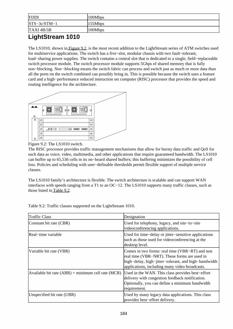
FDDI 100Mbps
STS−3c/STM−1 155Mbps
TAXI 4B/5B 100Mbps
LightStream 1010
The LS1010, shown in Figure 9.2, is the most recent addition to the LightStream series of ATM switches usedfor multiservice applications. The switch has a five−slot, modular chassis with two fault−tolerant,load−sharing power supplies. The switch contains a central slot that is dedicated to a single, field−replaceableswitch processor module. The switch processor module supports 5Gbps of shared memory that is fullynon−blocking. Non−blocking means the switch fabric can process and switch just as much or more data thanall the ports on the switch combined can possibly bring in. This is possible because the switch uses a featurecard and a high−performance reduced instruction set computer (RISC) processor that provides the speed androuting intelligence for the architecture.
Figure 9.2: The LS1010 switch.The RISC processor provides traffic management mechanisms that allow for bursty data traffic and QoS forsuch data as voice, video, multimedia, and other applications that require guaranteed bandwidth. The LS1010can buffer up to 65,536 cells in its on−board shared buffers; this buffering minimizes the possibility of cellloss. Policies and scheduling with user−definable thresholds permit flexible support of multiple serviceclasses.
The LS1010 family’s architecture is flexible. The switch architecture is scalable and can support WANinterfaces with speeds ranging from a T1 to an OC−12. The LS1010 supports many traffic classes, such asthose listed in Table 9.2.
Table 9.2: Traffic classes supported on the LightStream 1010.
Traffic Class Designation
Constant bit rate (CBR) Used for telephony, legacy, and site−to−sitevideoconferencing applications.
Real−time variable Used for time−delay or jitter−sensitive applicationssuch as those used for videoconferencing at thedesktop level.
Variable bit rate (VBR) Comes in two forms: real time (VBR−RT) and nonreal time (VBR−NRT). These forms are used inhigh−delay, high−jitter−tolerant, and high−bandwidthapplications, including many video broadcasts.
Available bit rate (ABR) + minimum cell rate (MCR)Used in the WAN. This class provides best−effortdelivery with congestion feedback notification.Optionally, you can define a minimum bandwidthrequirement.
Unspecified bit rate (UBR) Used by many legacy data applications. This classprovides best−effort delivery.
184

UBR + MCR A unique Cisco class for best−effort data trafficdelivery with a specified minimum bandwidth. Thisclass is used in a LAN for high−end resourceapplications or in a WAN with an ATM for aguarantee of a certain amount of bandwidth (alsocalled a committed information rate [CIR]).
One of the great features of the LightStream 1010 switch is its ability to use the same interface modules as theCisco Catalyst 5500 series of switches. This feature allows the LS1010 to be controlled in the same way as theCatalyst 5500 series, with the AtmDirector, CiscoView, and CiscoWorks for Switched Internetworks (CWSI)software available from Cisco.
LightStream 2020
The LS2020 is one of Cisco’s most powerful LAN, WAN, backbone, campus, and multiservice−type ATMswitches. This switch offers cost−effective bandwidth coupled with superior QoS handling in the network.Several other features make this switch a perfect solution for ATM: This switch works well with existingdevices and will scale well with future technologies and applications. The switch supports not only ATM butalso fastpacket switching applications, which means that it can support Frame Relay, circuit emulation, andLAN technologies such as Fiber Distributed Data Interface (FDDI) and Ethernet.
Switching and communications on the LS2020 are performed at wire speed, so no noticeable latency is causedby the switch processor or the Application−Specific Integrated Circuits (ASICs) used to switch data trafficfrom one interface to another. Processing tasks are handled by three components based solely on the speedrequired for each task. Let’s take a look at these three components:
Line card—Used when a particular function must be completed in a tenth of a millisecond or less.Such functions include implementing traffic policies and cell forwarding.
•
Line card control processor—Performs complex tasks that must be completed in a tenth of amillisecond or less. These functions include interface management, error handling, and line−up andline−down protocol processing.
•
Network processor software—Performs less critical processing that can be handled in more than atenth of a millisecond, such as cell processing and network management request processing.
•
The LightStream 2020 processor card is shown in Figure 9.3.
Figure 9.3: The LightStream 2020 processor card.The LS2020 switch can use a software package called ControlStream, which is a traffic managementapplication used to control data traffic. This software allows very high line utilization while at the same timemaintaining users’ QoS guarantees. ControlStream software employs congestion avoidance and traffic controltechniques that allow network links to operate at high levels of utilization by scaling back data that has amuch lower priority, including data traffic that is tolerant to traffic delays in the network. As a result, trafficselection can occur at congestion points in the network.
The LightStream 2020 uses an internal routing mechanism to provide a path through an ATM virtual channelconnection (VCC). These routing mechanisms allow the LS2020 network to provide paths through permanentvirtual connections (PVCs) and switched virtual connections (SVCs). Through these virtual connections, theLS2020 supports synchronous connections over ATM user−network interface (UNI) PVCs, Frame RelayPVCs, and circuit emulation PVCs. The switch also provides connections over physical LAN medias such asEthernet and FDDI.
185

Neighborhood Discovery Function
The neighborhood discovery function (NDF) can be used to provide a means for locating all the other nodes inthe network and to simplify the network configuration process. This tool helps to eliminate the need tomanually configure some of the attributes of interface modules inside the LS2020 switch.
CDF enables the switch to find nodes in the network; the found nodes are placed in a database to makeinternal routing decisions. This neighborhood discovery process runs on the network processor (NP) inside theLS2020’s attached network. The neighborhood discovery function provides two functions:
Discovering the local network topology• Determining the network processor processes•
Discovering the Local Network Topology
This function keeps track of the interface modules added to or removed from service manually or by ahardware fault. When another module is installed into the switch, the NDF automatically locates anddistributes functions to each network processor. If an interface module is removed from the switch, NDF mustbe used to move processes running on that network processor to another or to terminate the processes if theyare no longer necessary.
Determining Network Processor Processes
When a resource is added to or removed from an LS2020, the NDF process notifies the global informationdistribution (GID) system. The GID then floods information about the change from the local networkprocessor module to all the network processors in the network. A function called the connection admissioncontrol (CAC) is used by the network processors to generate new routes through the network. Using thisprocess, the internal routing module provides a directed set of links from one source node to a destinationnode, providing link state and bandwidth information that can be advertised throughout the network.
Virtual Path Connections
Virtual path (VP) is a generic term used to define more than one virtual channel directed to the same ATMendpoint. A virtual path essentially makes for a much larger pipe by combining the redundant paths andcreating a logical grouping of virtual connections between multiple ATM sites. The advantage of using VPs inan ATM network is that they enable cell streams from multiple users to be bundled together, resulting intransit over multiple links that is much faster than transit over one link. This process is referred to asload−sharing. In an ATM cell (discussed in Chapter 8), the Virtual Path Identifier (VPI) field in the cellheader identifies the VP. If a virtual circuit (VC) cell is traversing the network, the network pays attention tothe Virtual Channel Identifier (VCI) field.
There is another reason to use a VP between LightStream switches. This path can be used if an end user needsto define the route of certain ATM cells in a manually defined manner that must remain entirely transparent tothe network service provider.
Before you can enable a PVC and an SVC between any two endpoints in the network, an internal routingdatabase must first be established. The internal database is established during the network configurationprocess by downloading the necessary configuration information to each of the LS2020 switches installed inyour network. An internal routing module keeps the database information up to date with the requiredinformation that confirms the state of every link in the network.
This routing database is replicated from the NP used in each of the LS2020 switches in the network. Thedatabase is synchronized with the other ATM switches in the network; the ATM switches then use a routing
186

algorithm to determine the path for any data that arrives and needs to be switched through the network. Therouting algorithm calculates the minimum distance path through the network, verifies the availability ofbandwidth, and then sets up a connection between the two ATM endpoints in the network. The routingalgorithm can use metrics to determine the least−cost route for setting up a virtual connection.
A route that is selected through the route generation function is based on the smallest number of hops to thedestination. If two equal paths exist, the routing algorithm uses the bandwidth of the links as the tie−breaker:It uses the fastest link with the most available bandwidth.
When a route needs to be generated, the routing algorithm creates the most efficient route based on thefollowing information:
Source and destination addresses (the internal addresses used to designate the VCC endpoints in thenetwork)
•
Bandwidth type (indicates the pool to be used for allocation, data, or control purposes)• Service specification of the desired bandwidth or a minimum acceptable bandwidth•
Scaling factors allow for a partial allocation of bandwidth for certain types of data traffic. The primary scalingfactor is not definable and is always set to 1. A secondary scaling factor can be defined by an administrator;it’s typically set to a range of 1 to 2 percent.
When identifying a minimum acceptable bandwidth, you must set a parameter that will be an enforced rate forthe VCC. This parameter will make the routing algorithm choose a link that has bandwidth equal to or greaterthan the assigned minimum acceptable bandwidth value. Doing so prevents the possibility of an output portsending data at a greater rate than an intermediate link can handle and guarantees a certain amount ofbandwidth for those applications that require it.
LightStream Troubleshooting Tools
The LightStream series of Cisco switches has many troubleshooting and monitoring tools. The boot processcan be used to find hardware or software problems, certain protocols can be used for troubleshooting, and aunique tool called a snooping mechanism allows all or some of the connections to be transparently mirrored toa port. Let’s take a better look at these troubleshooting tools in the following sections.
LightStream Boot Process
When you power−on a LightStream for the first time, you should be able to access the console port. Withinthe first few seconds of turning on the power, you should see the following three lines:
System Bootstrp, Version 201 (1025), SOFTWARECopyright (c) 1986−1996 by Cisco SystemsASP processor with 16384 Kbytes of main memory
These lines indicate how much memory is installed in the switch. Checking the amount of memory installedin the switch against the amount displayed here can identify a hardware problem. If the bootstrap fails to load,the boot ROM could have a problem. If the switch has no configuration, it will default to setup mode.
If you see the following notice during the boot process and you’re prompted to set up the switch, then theinstalled nonvolatile RAM (NVRAM) may have a problem—particularly if a saved configuration existedwhen the power was recycled. Let’s take a look:
Notice: NVRAM invalid, possibly due to a write erase. — System Configuration Dialog —At any point you may enter a question mark ’?’ for help.Use ctrl−c to abort configuration dialog at any prompt.
187

Default settings are in square brackets ’[]’Would you like to enter the initial configuration dialog? [yes]
From this prompt, you can enter the initial configuration dialog or decline and manually enter theconfiguration. This choice allows an administrator to use the Command Line Interface (CLI) on theLightStream switch. If you are not familiar with configuring a LightStream switch, you may want to continueusing the System Configuration Dialog screen.
Supported Troubleshooting Protocols
LightStream switches support many protocols, such as Bootstrap Protocol (BOOTP) and Telnet, for remoteaccess to the switch and autoconfiguration. In−band management access is possible through the ATMinterfaces or the Ethernet port. Out−of−band management can be handled by the console port or either of thetwo serial ports. One serial port allows a dedicated port to attach a local terminal, and one can be used toattach an external modem for dial−in access through an analog telephone line.
Trivial File Transfer Protocol (TFTP) can be used for remote access to upload new firmware upgrades, saveconfigurations, or upload configurations.
Note Security for LightStream switches can be provided by the Cisco IOS software or aTerminal Access Controller Access Control System Plus(TACACS+)/authentication, authorization, and accounting (AAA). The Cisco IOScan be configured with multiple password levels. A TACACS+/AAA server can beused for remote access validation.
Snooping Mechanisms
Snooping mechanisms used by the LightStream 1010’s ports allow a mirrored connection from one or moreports to be mirrored to another port. As a result, any data on a selected mirrored port will be copied and sent tothe mirror port. This process is completely transparent to the end devices connected to the port or ports beingmonitored, and the data can be analyzed by an external ATM analyzer attached to the mirrored port.
Snooping mechanisms are one of the most important monitoring and troubleshooting tools used in ATMswitches. ATM analyzers can be used to monitor the traffic flows in and out of the selected ports. No externaldevices can be connected to monitored ports to easily identify problems associated with ATM.
Multiprotocol Over ATM
Multiprotocol Over ATM (MPOA) enables the fast routing of internetwork−layer packets across anonbroadcast, multiaccess (NBMA) network. MPOA replaces multihop routing with point−to−point routingusing a direct VCC between ingress and egress edge devices or hosts.
Two components will be discussed here:
MPOA Server (MPS)• MPOA Client (MPC)•
The MPS
The MPS supplies the forwarding information used by MPCs. Once the MPS receives a query from a client, itresponds with forwarding information. MPOA uses Next Hop Resolution Protocol (NHRP) to support thequery and response. The MPS on the router can also terminate shortcuts.
Although, a router is usually designated as an MPS, it can also be designated as an MPC.
188

The MPC
Configuring an MPC on a router provides router−initiated and router−terminated shortcuts for non−NBMAnetworks. The MPC functionality involves the following:
Data−plane and control−plane VCC management• Ingress/egress cache management• MPOA frame processing• MPOA protocol and flow detection•
An MPC identifies packets sent to an MPOA−capable router over the NBMA network and establishes ashortcut VCC to the egress MPC, if possible.
Configuring the Hostname
You can change the default prompt of Switch> and distinguish a switch from other devices in your networkby naming it. The following code lists the command to change the prompt name to CoriolisLS1010> (thissetting has only local significance on the switch):
Switch> enable
Switch# configure terminalEnter configuration commands, one per line. End with CNTL/Z.
Switch(config)# hostname CoriolisLS1010CoriolisLS1010(config)#
Configuring an Enable Password
In order to keep unauthorized people from making configuration changes on your switch, you should use theenable password command followed by the new password. Let’s take a look at an example:
Use the enable command to enter Privileged EXEC mode:
CoriolisLS1010> enable
1.
Use the config terminal command to enter Global Configuration mode:
CoriolisLS1010# config terminal
2.
Use the enable password command followed by a password to configure the enable password:3.
CoriolisLS1010(config)# enable password book1
Configuring the Processor Card Ethernet Interface
You must configure the Ethernet port on the processor card in order to allow Telnet access to the switch CLI.To configure the Ethernet interface, you must have local administrative access. Connect a PC or workstationto the console port on the processor card and follow these steps:
Use the enable command to enter Privileged EXEC mode:1.
189

CoriolisLS1010> enable
Use the config terminal command to enter Global Configuration mode:
CoriolisLS1010# config terminal
2.
You must identify the route for traffic to take to the internal network (referred to as a static route)using the ip route command, as shown here:
CoriolisLS1010(config)# ip route 63.78.127.0 255.255.255.0 ethernet 0
3.
Enter Interface Configuration mode for the Ethernet interface:
CoriolisLS1010(config)# interface ethernet 0
4.
Assign the IP address and subnet mask to the interface just as you would a switch or router Ethernetinterface, and then exit:
5.
CoriolisLS1010(config−if)# ip address 63.78.127.2 255.255.255.0CoriolisLS1010(config−if)# ^CCoriolisLS1010#
Configuring Virtual Private Tunnels
A virtual private tunnel provides a way to link two private ATM networks across a public network. This typeof network only supports PVCs. Connecting this way provides a permanent path through the public network.The public network trunks all the virtual channels in the VP between the two networks. The followingexample shows how to configure the VP tunnel when the VPI equals 2:
Use the enable command to enter Privileged EXEC mode:
CoriolisLS1010> enable
1.
Use the config terminal command to enter Global Configuration mode:
CoriolisLS1010# config terminal
2.
Enter the interface on the module:
CoriolisLS1010(config)# interface atm 3/0/2
3.
Identify the private virtual path (PVP) number:
CoriolisLS1010(config−if)# atm pvp 2
4.
Create an ATM subinterface. This example uses the PVP number as the sub−interface number:5.
CoriolisLS1010(config−if)# interface atm 3/0/2.2CoriolisLS1010(config−subif)# endCoriolisLS1010#
Verifying an ATM Interface Connection Status
When the VP tunnel is configured correctly, the connection status displayed in the AutoCfgState shows theword completed. You display this information by using the show atm interface command followed by theATM interface. Let’s take a look at an example of the command:
CoriolisLS1010# show atm interface atm 3/0/2.2
Interface: ATM3/0/2.2 Port−type: vp tunnelIF Status: UP Admin Status: up
Auto−config: enabled AutoCfgState: completed
190

IF−Side: Network IF−type: NNIUni−type: not applicable Uni−version: not applicable
CoriolisLS1010#
Viewing the Configured Virtual Connections
To view the configured virtual connections, use the show atm vp command as shown here:
CoriolisLS1010# show atm vp
Interface VPI Type X−Interface X−VPI StatusATM3/0/2 2 PVP TUNNEL
CoriolisLS1010#
Configuring the LECS ATM Address on a LightStream 1010Switch
To configure the LAN Emulation Configuration Server (LECS) ATM address on a LightStream 1010 switch,follow these steps:
Use the enable command to enter Privileged EXEC mode.1. Use the config terminal command to enter Global Configuration mode.2. Enter Interface Configuration mode for the correct ATM interface.3. Use the atm command followed by the address of the LECS:4.
atm lecs−address atm−address
Tip To verify the address configuration, use the show atm ilmi−configuration command.
Configuring the Advertised LECS Address
To configure the LECS address advertised by the switch to the end system, use the atm lecs−address−defaultGlobal Configuration command. The syntax is as follows:
atm lecs−address−default lecsaddress [sequence #]
Related solutions: Found on page:
Configuring a LEC for an ELAN 271
Configuring the LECS 273
Viewing the LANE Configuration
To view the LANE configuration on a LightStream series switch, use the show lane command as follows:
CoriolisLS1010# show lane
LE Server ATM2/0.2 ELAN name: elan1 Admin: up State: operational
type: ethernet Max Frame Size: 1516 ATM address: 47.0091810000000060707B8A01.1122334455AA.02 LECS used: 47.0091810000000060707B8A01.0060705A8F05.00 connected, vcd 1450
191

control distribute: vcd 1452, 3 members, 196 packets
proxy/ (ST: Init, Conn, Waiting, Adding, Joined, Operational, Reject,Term) lecid ST vcd pkts Hardware Addr ATM Address 1 O 1451 6 0060.705a.8f02 47.0091810000000060707B8A01.0060705A8B12.01 2 O 1455 10 00e0.d7b1.ba12 47.0091810000000060707B8A01.112233461176.02 3P O 1466 59 0090.a2fb.b430 47.0091810000000060707B8A01.009086FB1021.01
LE BUS ATM2/0.2 ELAN name: elan1 Admin: up State: operational type: ethernet Max Frame Size: 1516 ATM address: 47.009181000000006007B8A01.1B2133CC51BA.02 data forward: vcd 1454, 3 members, 244 packets, 5 unicasts
lecid vcd pkts ATM Address 1 1453 32 47.0091810000000060707B8A01.0060705A8B12.01 2 1458 28 47.0091810000000060707B8A01.112233461176.02 3 1467 58 47.0091810000000060707B8A01.0060705A8B12.01
LE Client ATM2/0.2 ELAN name: elan1 Admin: up State: operational
Client ID: 2 LEC up for 22 minutes 53 seconds Join Attempt: 605 HW Address: 00e0.f9b1.b410 Type: ethernet Max Frame Size: 1516 ATM Address: 47.0091810000000060707B8A01.112233461176.02 VCD rxFrames txFrames Type ATM Address 0 0 0 configure 00.000000000000000000000000.000000000000.00 1456 1 10 direct 47.0091810000000060707B8A01.112233461176.021457 196 0 distribute 47.0091810000000060707B8A01.112233461176.021459 0 28 send 47.0091810000000060707B8A01.112233461176.021460 245 0 forward 47.0091810000000060707B8A01.112233461176.02
Related solution: Found on page:
Verifying a LEC Configuration on an ELAN 272
Viewing the Installed Modules
Just as you can on a Catalyst switch, you can use the show module command to look at the installed moduleson the LightStream switch. Remember, the LS1010 can use the same modules as the 5500 series switch.Here’s an example of the command’s results:
CoriolisLS1010> show module
Mod Module−Name Ports Module−Type Model Serial−Num Status—— —————————————— ———— ———————————————————— ———————— —————————— ——————2 2 100BaseTX Supervisor WS−X5509 002261212 ok3 24 3 Segment 100BaseTX E ws−x5223 000000021 ok4 1 MM OC−3 ATM WS−X5155 003125674 ok5 2 MM MIC FDDI WS−X5101 002774545 ok6 Route Switch Ext Port 7 1 Route Switch WS−X5302 002274941 ok
Mod MAC−Address(es) Hw Fw Sw——— ———————————————————————————————————————— —————— —————— —————————2 00−e0−a3−a5−00−00 thru 00−e0−a3−a5−03−ff 1.2 2.2(1) 3.1(1)3 00−60−83−42−e4−4b thru 00−60−83−42−e4−4d 0.1 2.2(4) 3.1(1)4 00−40−0b−43−02−64 1.0 1.3 2.25 00−60−3e−cd−42−95 1.0 1.1 2.1(2)7 00−40−0b−91−42−16 thru 00−40−0b−91−42−17 1.0 20.2 11.2
Mod Sub−Type Sub−Model Sub−Serial Sub−Hw
192

——— ———————— ————————— —————————— ——————2 EARL 1+ WS−F5511 0002278010 1.0
Mod SMT User−Data T−Notify CF−St ECM−St Bypass——— ——————————————————— ———————— —————— ——————— ——————5 WorkGroup Stack 30 isolated in absent
CoriolisLS1010>
Configuring the MPC
This example configures the MPC and binds an LEC to the MPC:
Define the MPC with the name THEMPC, as follows:
mpoa client config name THEMPC
1.
Specify the ATM interface to which the MPC is attached. In this example, the interface is 1/2:
interface ATM 1/2
2.
Associate the interface to the MPC named MYMPC as follows:
mpoa client name MYMPC
3.
Enter Subinterface Configuration mode for the ATM interface that contains the LEC to which youwill bind the MPC:
interface atm 1/2.1
4.
To bind a LANE client to the specified MPC, use this command:5.
lane client mpoa client name MYMPC
Configuring the MPS
The following example shows the proper configuration of the MPS and attaches the MPS to a hardwareinterface:
Define the MPS named THEMPS:
mpoa server config name THEMPS
1.
Enter Interface Configuration mode for the ATM interface:
interface ATM 1/1
2.
Attach the MPS called THEMPS to a hardware interface:3.
mpoa server name THEMPS
Changing the MPS Variables
MPS variables affect only a particular MPS. Perform the following tasks starting in MPS Configuration mode:
193

To identify an MPS with a specific name, use the following command:
mpoa server config name mps−name
1.
The ATM address that specifies the control ATM can be optionally identified using this command:
atm−address atm−address
2.
To specify the network ID, use the following command:
network−id id
3.
To identify a keepalive time value, use the following command:
keepalive−time time
4.
To change the holding−time value, use the following command:5.
holding−time time
Monitoring the MPS
To monitor the MPS, use the following command in Privileged EXEC mode:
show mpoa server
Enabling ILMI Autoconfiguration
The following example shows how to enable Integrated Local Management Interface (ILMI)autoconfiguration on interface ATM 3/1/2:
CoriolisLS1010(config)# interface atm 3/1/2CoriolisLS1010(config−if)# atm auto−configurationCoriolisLS1010(config−if)#
%ATM−5−ATMSOFTSTART:Restarting ATM signaling and ILMI on ATM3/1/2
Configuring LANE on a LightStream 1010
To configure a LANE client connection from a remote ATM switch router to the processor card (CPU) of alocal switch, follow these configuration steps:
Use the enable command to enter Privileged EXEC mode:
CoriolisLS1010> enable
1.
Use the config terminal command to enter Global Configuration mode:
CoriolisLS1010# config terminal
2.
Enter Subinterface mode for the processor card using the followingcommand:
CoriolisLS1010(config)# interface atm 0[.subinterface]
3.
You must specify an ATM address to override the automatic ATM address assigned to a LANEclient:
CoriolisLS1010(config−if)# lane client−atm−address atm−address−template
4.
194

Use the lane client ethernet command followed by the name of the ELAN to configure a LANEclient:
5.
CoriolisLS1010(config−if)# lane client ethernet elan−name
Powering on the LightStream 100 ATM Switch
To power on the LightStream 100 ATM switch, use the following steps:
Turn the power switch to the on position, which is depicted by a symbol that looks like this: (|).1. The switch will execute the diagnostic power on self test (POST). The results can be viewed byconnecting to the console port. If there is a problem with the POST, you can see the error on screenand you will be notified with a lit alarm LED. A red alarm LED indicates a failure that must beresolved before the boot process can continue. The screen displays NG (for “no good”) when a POSTitem doesn’t pass; you will see a Not Installed error if the switch has an empty slot.
2.
Configuring the LS100 Switch
To perform the basic configuration on the LS100 switch, follow these steps:
Use the show interface or show module command to display the interfaces installed. Make sure thereis a line number for each module installed.
1.
If a card or module does not appear, turn off the power, reseat the module or card, and turn the powerback on. If the card or module still does not appear, contact Cisco’s Technical Assistance Center(TAC).
2.
Use the enable command to enter Privileged EXEC command mode. The system requests apassword; if one has not been assigned, just hit the Enter key.
3.
Type in a lowercase c to allow changes. The prompt changes from > to #.4. You must set the time and date on the LS100 switch. The following command shows how to set thetime to 7:37 p.m. in military time and the date to November 30, 2000:
CoriolisLS100# set time 00−11−30 19:37:00 System Timer is set. 00−11−30 19:37:00
5.
Use the set clock command to set the clock to synchronize the time with the other connectedLightStream switches. This step will also determine if the switch is a master or slave timesynchronizer unit.
6.
Use the set interface command to register a line. This command sets the interface type touser−network interface (UNI) or network−to−network interface (NNI), the standard bodyconformance to either ATM or ITU, the length of the VPI valid bits, and the length of VCI valid bits.
7.
Use the pvc establish command to configure a point−to−point PVC.
Warning This command becomes active immediately.
8.
To optionally set PVC multicast, use the pvc add command to add the endpoint. The pvc addcommand can also be used to add a PVC endpoint for point−to−multipoint connection. If you areusing an SVC, use the route add command instead of the pvc add command. The pvc establishcommand allows you to enter the line number, VPI, and VCI.
Note To delete an endpoint, use the pvc remove command.
9.
Use the save command to save the configuration data.10. Use the exit command to exit Privileged EXEC command mode.11.
195

Recovering a Lost Password
To recover a password, such as that used for the root account, look at the following example (the output isquite long, so unnecessary information has been omitted):
Type ‘. to get a Test and Control System (TCS) hub prompt. user name:’.TCS HUB<> At the TCS hub prompt, use reset and connect to reset the NP card.
Note: Be prepared to press Enter at the prompt, as shown below. TCS HUB<> reset 1TCS HUB<> connect 1
Memory Autosizing…(32Meg)…DoneClearing 32Meg Memory…DoneNP1 POST Version 0.220 Nov 23 1994
NP1 POST SUMMARY:————————0 Tests Failed
System will boot in 5 seconds: hit to interrupt. Press Enter now. Choose option 5 to boot the system for a single−user: Network Processor bootstrap(version 1.3: Sep 13 1993)1 − Boot ATM switch application2 − Begin full installation with boot from floppy disk3 − List contents of hard disk root directory4 − List contents of floppy disk root directory5 − Boot system single−user6 − Escape to full set of bootstrap options7 − Extended helpOption> 5
booting: drive:0, partition:0, kernel:"lynx.os", flags:0x4100Resetting SCSI busKernel linked for 0xea010000LOAD AT 0x10000483328+49152+262564[+62796+51901]TOTAL SIZE: 909744 at 0x1001cSTART AT 0x10020NP memory size: 32 MBILACC: EEPROM enet addr:8:0:8:0:ae:61, Silicon Rev:0x5, IB:0xea1dfce0virtual console: IB: 0xea1dfe68NCR 53C710: Chip Revision: 0x2, IB: 0xec18e000
Memory Autosizing…(32Meg)…DoneClearing 32Meg Memory…DoneNP1 POST Version 0.220 Nov 23 1994
NP1 POST SUMMARY:————————0 Tests Failed
booting: drive:0, partition:0, kernel:"lynx.os", flags:0x5104Resetting SCSI busKernel linked for 0xea010000LOAD AT 0x10000483328+49152+262564[+62796+51901]TOTAL SIZE: 909744 at 0x1001cSTART AT 0x10020NP memory size: 32 MBILACC: EEPROM enet addr:8:0:8:0:ae:61, Silicon Rev:0x5, IB:0xea1dfce0virtual console: IB: 0xea1dfe68
196

NCR 53C710: Chip Revision: 0x2, IB: 0xec18e000
LynxOS/68040−MVME167 Version 2.1.0Copyright 1992 Lynx Real−Time Systems Inc.All rights reserved.
LynxOS release 2.1.0, level 1: NP−LynxOS #112: compiled Nov 08 1994 19:49:33Single−user bootsingle−user$ Type ’. to get a TCS hub prompt: single−user$ ’.TCS HUB<>Reset the NP card:TCS HUB<> reset 1TCS HUB<> connect 1
Memory Autosizing…(32Meg)…DoneClearing 32Meg Memory…DoneNP1 POST Version 0.220 Nov 23 1994
NP1 POST SUMMARY:————————0 Tests Failed
The following accounts do not have passwords: root fldsup npadmin oper
Install a password on the root account? (y/n) [y] yChanging password for rootEnter new password:Retype new password:
Install a password on the fldsup account? (y/n) [y] yChanging password for fldsupEnter new password:Retype new password:
Install a password on the npadmin account? (y/n) [y] yChanging password for npadminEnter new password:Retype new password:
Install a password on the oper account? (y/n) [y] yChanging password for operEnter new password:Retype new password:
Starting VM system … Virtual Memory Engaged!inetd startedStarting crond …Initializing the switch hardware interface …Using switch A, cards are NOT synchronized, fast cutover is supportedPCP version: 0x410, CMP version: 0x12, FSU version 0x109Starting the switch softwareLightStream 2020 Version 2.0.6Copyright 1993 LightStream Corp. All rights reserved.Portions copyright 1992 by Lynx Real−Time Systems Inc., 1983 by the Regentsof the University of California, 1988 and 1990 by Paul Vixie, and 1991 bySNMP Research Inc.
This software contains unpublished proprietary and trade secret informationof LightStream Corp.
LightStream 2020 Software provided to the U.S. Government is subject to thenotices on the software and on the LightStream user documentation copyrightpage.PROGRAM: cbuf: (ls2_0) compiled Nov 08 1994 @ 23:33:35 [pid:50]Login as root and check the new password:
197

user name: coriolisuserpassword:
This process changes the password and recovers any lost passwords.
198

Chapter 10: Layer 2 Redundant Links
In Depth
If your company has ever experienced a critical work stoppage due to a downed server or a network outage,you understand how critical it is to implement redundancy in your network. No matter what happens with anindividual link in your network, the other links should take over using redundant links.
The Spanning−Tree Protocol (STP) provides the components needed to ensure consistent network availabilitywhen a problem occurs with a link in the network. Not only can you use these redundant links in the case of anetwork failure, but—because your company is paying to implement the redundant links—it makes sense toload balance over those links and use them to handle twice the traffic load when they are operating correctly.
This chapter will concentrate on using Layer 2 redundant links as well as using STP to block redundant linksto prevent data loops from forming in the network. Layer 3 devices, which are typically routers, give therouting protocols the responsibility for making sure routing loops do not occur in the network.
Layer 2 Switching Overview
Here’s a quick reminder of how Layer 2 switching works. The Open System Interconnection (OSI) Layer 2uses the Network Interface Card’s (NIC) physical address, called the Media Access Control (MAC) address,which is assigned to the card by the vendor of the card. In Chapter 2, I covered how Application SpecificIntegrated Circuits (ASICs) are used to build the switches’ Content Addressable Memory (CAM)table—similar to a router’s routing table—which is used to calculate and maintain loop−free paths through thenetwork.
At Layer 3, you use software to create filtering tables and make filtering decisions. Switches use hardwareASIC chips to help make filtering decisions—filtering with hardware is much faster.
Both switches and bridges track the source hardware address of each frame received on each port and enterthis information in their filtering table. This table allows the bridge or switch to make a forwarding or filteringdecision for data it receives based on the information learned.
Bridges have up to 16 ports but only one instance of STP for all the ports. Cisco switches can have hundredsof ports and an instance of STP running for each virtual LAN (VLAN). On some Cisco Catalyst switches,thousands of instances of STP can be running on the network.
When a frame is received on a switch port, the switch looks at the destination address in the frame header andcompares the address with known source addresses the switch has learned to see if it knows the port thedestination resides on. If the address is known, the switch forwards the frame to the destination port. If theaddress is unknown, the switch forwards the frame to all its ports, which are members of the same broadcastdomain as the arriving switch port. This broadcast domain consists of all the members of the same VLAN asthe port of arrival. This domain does not necessarily include just VLAN members on the switch of arrival—itcan include all the switches in the network that share the same VLAN number.
Frames
A switch will typically receive three types of frames without a specific destination. These frames in turnbecome a broadcast and are flooded out all the ports except for the port of arrival. These frame types are:
199

Broadcast frames• Multicast frames• Unknown unicasts•
Broadcast and Multicast Frames
Broadcast and multicast frames are unique in that neither has a specified destination hardware address. Thesource address is also the hardware address of the device that sent the frame. In the case of broadcasts, thedestination address shown in the header is all 1s, indicating that the broadcast goes to all nodes in a network.A multicast specifies a network but changes all the host address bits to all 1s. For example, a broadcast andmulticast in binary would appear as shown in Table 10.1.
Table 10.1: Broadcast and multicast destination addresses.
Frame Type Binary Value Broadcast Address
Broadcast 11111111.11111111.11111111.11111111255.255.255.255
Multicast 00001010.00000001.11111111.1111111110.1.255.255When a switch receives a broadcast or a multicast, the frame is sent out all the ports of the switch by default,with the exception of the port on which the frame arrived. VLANs can be used to break down the broadcastsinto smaller broadcast domains. In the case of a VLAN, if a broadcast arrives on a port assigned to VLAN 5,only ports assigned to VLAN 5 will receive the broadcast.
Unknown Unicasts
An unknown unicast is similar to a broadcast. This type of unicast is sent when a destination address isunknown by the switch. In this case, the bridge forwards the frame just like a broadcast; the frame is sent outall ports except the port on which it arrived.
Layer 2 Network Loops
To sum up STP in one sentence, Spanning Tree Protocol is used to allow the Layer 2 network to have morethan one path to a destination by blocking ports that can cause a packet to make a complete circle through thenetwork. This circle, shown in Figure 10.1, is known as a data loop. The data will move in a continuous circleunless some protocol or algorithm is used to stop the data or a maximum time to live is assigned to the datapacket. STP reliably monitors the network topology to find all the links and make sure that data loops do notoccur.
Figure 10.1: A network with more than one path in the network. Data can return to the source node on asecond link, causing a data loop.Manufacturers needed a consistent standard that they all could use to block redundant paths through anetwork. Digital Equipment Corporation (DEC) answered the call and submitted to the Institute of Electrical
200

and Electronics Engineers (IEEE) a protocol similar to STP to become a networking standard. However, afterthe IEEE 802 committee revised it into what is now known as the IEEE 802.1D standard (Spanning TreeProtocol), the protocol differed just enough from DEC’s version that they were incompatible.
Danger! Data Loops!
Data loops can easily become a network disaster. A transparent bridge always likes to retransmit a broadcast itreceives and never mark the frame with a time to live (TTL) or an identifier that says “Hey I started here!” or“I’ve been around here a few times already.” The result? Your transparent bridge keeps re−creating broadcastsin an expanding fashion. The bridge actually begins rebroadcasting broadcasts. Think this situation will lastforever? Not likely—the bridges will eventually cause a broadcast storm and bring down the entire network.
STP fixes this problem and forces all the redundant data paths into a blocked state. By blocking the paths todestinations other than the given root path, STP creates only one path through the network. If any of theforwarding paths through one of the network segments in the spanning tree become unreachable, STP willreconfigure the spanning−tree topology and use the once blocked links in the network. STP calculates thenetwork topology using the Spanning−Tree Algorithm (STA).
To avoid confusion, let me clarify that the Spanning−Tree Protocol and the Spanning−Tree Algorithm are twoseparate entities. STA chooses a reference point in the network and calculates the redundant paths to thatreference point. If the STA finds a redundant path, it will choose one path to forward and the redundant pathsto block. Using this process, STP and the STA effectively sever all the redundant links within the network.
STA is based on the graph theory developed by Edsger Dijkstra to construct a loop−free subset of the networktopology. Let’s take a look at this theory.
Edsger Dijkstra’s Graph Theory
The STA uses solutions obtained by a graph theory also known as the Shortest Path Algorithm. As Imentioned earlier, this algorithm is used to construct a loop−free subset of the network’s topology. The sametheory is also used in other link state protocols, such as Open Shortest Path First (OSPF), to calculate routingsolutions. The theory states that for a connected graph consisting of interfaces and edges connecting pairs ofinterfaces, a spanning tree of the edges maintains the connectivity of the graph while containing no loops.
The algorithm provides a directed graph where each link is represented by vertices and weighted edges, asshown in Figure 10.2. Each link represents a cost. The weighted edges, which usually have more hops in thelink than do the straight−through points, are assigned higher values. Each link in the path has a value, and thetotal of the values to a given point or destination is the total weighted value of the path. The lowest totalweighted value represents the most efficient path from one point to another point.
201

Figure 10.2: An example of a directed graph.STA assigns each switch in the network a unique identifier. This identifier is one of the switch’s MACaddresses, as well as an assigned priority (explained in more detail later in this chapter in “The SelectionProcess”). After STA assigns each switch this unique identifier, it then assigns each port in every switch aunique identifier. This port identifier is typically the port’s own individual interface MAC address. Eachbridge port is then associated with a path cost, which represents the cost of transmitting a frame onto thenetwork through the port. Path costs are assigned by default, but can be assigned manually by a networkadministrator.
As I stated in the last section, the graph theory chooses a reference point in the network and calculates theredundant paths to that particular point in the network topology. After STP discovers all the links in thenetwork, the STA chooses a single path through the network and blocks the redundant links. It does so byelecting a root bridge. Let’s take a look at root bridges in the next section.
STP Root Bridges
When STP initially comes online in a network, one of its first actions is to use the STA to select a root bridgeand a root port. The root bridge is the bridge with the lowest−value bridge identifier. Switches or bridgesusing STP exchange multicast frames called Bridge Protocol Data Units (BPDUs) (discussed in the nextsection). All the switches on the network use these BPDUs to broadcast their bridge IDs to the other switchesin the network. After the root bridge is selected, the root ports on all other bridges are determined.
Switch A in Figure 10.3 is acting as the root bridge, calculating the least−cost path to switch D. Notice thenumbers associated with the root bridge’s path to each individual destination; the path with the lowest numberhas the highest priority. The higher the number between individual segments, the higher the cost oftransmitting a frame between those two segments. The port through which the root bridge can be reached withthe least amount of hops or cost determines a bridge’s root port; this is referred to as the least path cost.
202

Figure 10.3: The root bridge calculating the path cost to switch D.The lowest calculated path is not always the most ideal path. For example, if multiple high−speed links to adestination exist, the links may total more than the cost of a very slow link, such as a modem. Even though thestraight path has the fewest hops, it is much slower than using a high−speed, longer path. To overcome thisproblem, you as the administrator can manually change a slower−speed link to have a higher port cost, whichSTP will use to calculate a higher path cost. The goal is to make changes to the network so that the fastest,most efficient route to the root port is designated for the switch to use. The fastest links should always havethe lowest port costs.
A designated bridge is the bridge or switch on each LAN that provides the shortest route with the least pathcost. The designated bridge is the only bridge that is allowed to forward frames to and from the other bridges.A designated port on the switch is the port that connects the switch to the physical interface of the designatedbridge.
Bridge Protocol Data Units
BPDUs are messages passed between bridges and switches to help STP calculate and learn the topology of thenetwork. The multicast messages contain information that identifies the network link, the bridge presumed tobe the root bridge, the calculated root path cost, other STP bridges, port identifiers, and the age of theinformation contained in the message.
STP member bridges and switches exchange BPDU messages at configurable intervals—typically, every oneto four seconds. By default, BPDUs are sent out every two seconds on every port to ensure a stable networkwithout accidental data loops. Should one or more bridges fail or another STP member join the network,BPDU messages will help the other STP member bridges and switches to notice this change in the networktopology. The neighboring bridges will detect the lack of configuration messages and initiate an immediateSTA recalculation.
Note BPDU messages are never forwarded by any member. Instead, each STP bridge or switch makes adecision locally based on BPDU messages received. The switch or bridge then creates a new BPDUmessage based on the new information and sends that message out its ports.
Let’s take a look at the fields of a BPDU, as shown in Figure 10.4:
Figure 10.4: The 12 fields of a BPDU message.
Protocol Identifier—Contains 2 bytes and the value of zero.•
203

Version—Contains 1 byte and the value of zero.• Message Type—Contains 1 byte and the value of zero.• Flag—Contains 1 byte; only the first 2 bits are used. The topology change (TC) bit signals that therehas been a topology change. The topology change acknowledgment (TCA) bit is then set toacknowledge receipt of a configuration message with the TC signal bit set.
•
Root ID—Contains 8 bytes that identify the root bridge by listing a 2−byte priority followed by a6−byte ID.
•
Root Path Cost—Contains 4 bytes containing the cost of the path from the bridge sending theconfiguration message to the root bridge.
•
Bridge ID—Contains 8 bytes identifying the priority and ID of the bridge sending the message.• Port ID—Contains 2 bytes identifying the port from which the configuration message was sent. Thisfield allows loops created by multiple attached bridges to be detected immediately by STP.
•
Message Age—Contains 2 bytes specifying the amount of time since the root sent the configurationmessage on which the current configuration message is based.
•
MaxAge—Contains 2 bytes indicating when the current configuration message should be discarded.• Hello Time—Contains 2 bytes indicating the time period between root bridge configuration messages.• FwdDelay—Contains 2 bytes indicating the length of time that the bridge should wait beforetransitioning to a new state following a topology change in the network.
•
Timer’s affect the way BPDUs operate in a network and converge in the event of a data loop or networktopology change. Let’s take a look at these timers.
BPDU Timers
STP uses timers to prevent data loops and to determine how long it will take STP to converge after a linkfailure or change in the network topology. As frames and packets travel through the switched network, thisdata faces propagation delays. Propagation delays occur due to such things as bandwidth utilization, packetlength, switch processing, or any other port−to−port delay encountered as data traverses the network.
As a result of propagation delays, BPDUs can be late to their destinations, making the switch think that anetwork topology change has occurred. Because propagation delays can occur at any time in the network,when a switch port converts from a blocked state to a forwarding state, the port can inadvertently createtemporary data loops because it has not received a complete picture of the network topology.
To overcome network propagation delays, STP members use timers to force the ports to wait for the correcttopology information. The timers are set by default on the switch. Table 10.2 shows the three different STPtimers and the default timer settings based on a default setting of 2 for the Hello Time and 7 for the switchdiameter. Based on these assumptions, the network should always form a stable topology.
Table 10.2: The default STP timers and their default settings.
STP Timer Variable Description Default
Hello Time Determines how often the switchwill broadcast hello messages toother switches
2 seconds
Maximum Time/MaxAge Determines how long protocolinformation received on a port isstored by the switch
20 seconds
FwdDelay Determines how long listening andlearning will last before the portbegins forwarding
15 seconds
Selecting the root bridge is important in calculating the port cost in the network. The port cost from each childswitch in the network is calculated from the network’s root bridge. In the next section, we’ll take a look athow the BPDUs are used in the process of selecting a root bridge.
204

Parent and Child Switches
A switch’s diameter is a unit of measurement between the root switch and child switches. The root bridgecounts as the first switch. Each subsequent child switch out from the root bridge is counted to yield thediameter number. A parent switch brings you one switch closer to the root bridge, and a child switch takesyou one switch farther away from the root bridge.
Each root bridge can be configured with a diameter from a minimum of two switches to a maximum of sevenswitches. By modifying the diameter, you will subsequently change the timer values that are advertised by theroot to reflect a more accurate network diameter. For example, a diameter of 2 yields a MaxAge of 10 secondsand a FwdDelay of 7 seconds. Cisco recommends that you change the diameter to correctly reflect yournetwork rather than manually changing the timers.
Root Bridge Selection
One of the most important decisions that you make when configuring the STP protocol on your network is theplacement of the root bridge. In the spanning tree, the root bridge should be located as close as possible to thecenter of the network. Certain commands can help the administrator determine which device will become theroot bridge. The proper placement of the root bridge(s) optimizes the paths that are chosen by the STP toallow data traffic to flow through the network. It also provides deterministic paths for data to take.
In order to get the most optimal paths through the network, you must sometimes ignore the default root bridgeused by STP. This means you must manually configure the bridge that should be the root bridge, as well asthe secondary root bridge. The function of the secondary root bridge is to become the root bridge, should theoriginal root bridge fail.
Tip Typically, root bridges are Distribution layer switches, not Access layer switches. The rootbridge should never be a Core layer switch, because the Core layer’s responsibility is to movetraffic as quickly as possible.
The Selection Process
The root bridge selection process begins as soon as the switch powers up. The root bridge is the referencepoint in the network from which graph theory is used to calculate the cost of each link for each instance of aspanning tree. Using these calculations, the switches must determine if loops exist in the network and the pathcosts associated with each path through the network. The switch immediately assumes at startup that it gets tobe the root bridge, and it configures its bridge ID equal to the root ID in the BPDU. The bridge ID field of aBPDU message is actually made up of two parts, as follows:
Bridge priority—A 2−byte value set by the switch. By default, the priority is set to 0x8000 or 32,768.• Media Access Control (MAC) address—The 6−byte MAC address of the switch or bridge.•
These two fields of the bridge ID help an STP switch yield a value that can be compared with other switches’bridge IDs to determine which switch will become the root bridge. The lower the bridge ID value, the higherthe chance of a root−bridge assignment. If more than one switch has the same low bridge priority value, thebridge with the lowest MAC address then becomes the root bridge. Table 10.3 shows the bridge priorityvalues assigned by STP.
Table 10.3: The bridge priority values assigned by Spanning Tree Protocol.
Priority Assignment Value
Default bridge priority 32,768
205

Secondary root bridge priority 16,384
Root bridge priority 8,192The switches participating in STP (other than the root bridge) must form an association with the root bridgeshortly after the root bridge has been elected. Each switch examines each BPDU as it arrives on each port.When a switch receives the same information on more than one port, it is an indication that the switch has aredundant path to the root bridge. The switch then determines which port will forward data and which portswill be blocked from sending data. This decision is made by analyzing the path cost and port ID fields of theBPDUs.
Bridges look at the path cost first to determine if the port has the lowest−cost path to the root switch. If theport has the lowest port cost, the port is placed in forwarding mode. All the other ports that are receiving thesame BPDU information are placed in blocking mode.
In blocking mode, the port will still forward BPDU and system information to the switch processor. If thepath cost is equal, as in the case of identical links, the bridge looks at the port ID as a tie breaker. The portwith the lowest port ID forwards, and all other ports are blocked.
Port Costs, Path Costs, and Port Priorities
After the root bridge has been elected, all the switches determine the best loop−free path to the root switch.STP uses several different costs, with the port priority as the tiebreaker. The sum of all the port costs to adestination through all the ports the frames must travel makes up the path cost. Table 10.4 shows the defaultport cost and port priority assigned to each port.
Table 10.4: The default port settings for STP.
Variable Default
Port priority 32 (Except 1900 and 2820 series—128)
Port cost 62When the BPDU is sent to the other bridges, it carries the path cost. The spanning tree looks first at the pathcost and decides which ports should forward and which ports should be blocked. If the path costs are equal formore than one port, then the spanning tree looks at the port ID. The port with the lower port ID has priority,making that port the forwarding port. If the path cost and the port ID are the same, then the STP will use theport priority as the tiebreaker. We’ll look more at equal cost paths in the next section.
Tip On both the Command Line Interface (CLI) based IOS and the Set/Clear command−based IOS, youshould assign lower numbers to ports attached to faster media and higher numbers to ports attached toslower media. The defaults differ for media, as shown in Table 10.5.
Table 10.5: Examples of path cost calculations.
Physical Wire Speed Path Cost
10Mbps 100
100Mbps 10
155Mbps 6
1000Mbps (1Gbps) 1
10000Mbps (10Gbps) 1The port priority on each port can be modified to influence the links that will be forwarding. The port with thelowest priority value forwards frames for all VLANs. In the event that all ports have the same priority value,the port with the lowest port number will forward the frames. The possible port priority value range is from 0to 63.
206

Equal Cost Paths
If two or more links have the same root path cost, such as two identical links running between two switches,STA has a problem choosing the designated port or a root path through the network using the lowest pathcost. The bridge ID is used to determine the root bridge in the network and also the root port. By default, thepriority on all devices running STP is 32,768.
If two switches or bridges have the same priority value, then the MAC address is used to break the tie. Thebridge or port with the lowest ID wins. For example, let’s look at the two switches depicted in Figure 10.5.One switch uses the MAC address 0000.80ac.0000.1111, and the other switch uses the MAC address0000.80ac.0000.2222. The switch using 0000.80ac.0000.1111 would become the root bridge or the root port,depending on which decision the switch is making.
Figure 10.5: Two ports on two switches with equal cost paths through the network.We didn’t consider another option: As the administrator, you can assign a lower path cost to faster physicalmedia, or you can assign slower media a higher path cost. You can also decide which link to give a highercost path when multiple links are equal. The range of numbers that can be assigned to the port costs are 1through 65,535. Typically, the path cost is determined by dividing 1,000 by the physical wire speed inmegabits per second (Mbps), as shown in Table 10.5.
Note The path cost can never be lower than one.
STA recalculates the cost of using each link whenever a bridge joins the network or when a topology changeis detected in the network. This calculation requires communication between the spanning tree bridges, whichis accomplished through the passing of BPDU messages between switches.
Spanning Tree Convergence Time
The convergence time is the time it takes STP members to begin transmitting data on a redundant link after alink in forwarding mode has failed. It is also the initial period between the time an STP member powers upand when all the active links are placed in forwarding mode. In both cases, during the convergence time, nodata is forwarded.
Note Convergence is necessary to make sure that all devices have the same topology information.
Earlier in this chapter we discussed the STP default timers. The MaxAge default is set to 20 seconds and theFwdDelay is set to 30 seconds, because FwdDelay is used by both the listening and learning states (discussedin the next section). The values have meaning only at a root bridge. You can adjust FwdDelay and MaxAge;however, doing so may cause a data loop temporarily in more complex networks. The downtime could be ashigh as 50 seconds using the following formula:
2 * FwdDelay + MaxAge = Down Time
207

For example, the downtime caused by using the defaults would be the following:
2 * 15 + 20 = 50 seconds
Now that you have learned about the timers and how BPDUs operate in the network, let’s take a closer look athow ports transition through different states before forwarding data.
STP Port States
Each port participating in STP transitions through four port states, or modes, in a designated order before theport can forward frames it receives. These states are blocking, listening, learning, and forwarding. A fifthstate—the disabled state—can be manually configured by the switch.
Let’s look at the different port states and when each is used (see Figure 10.6):
Figure 10.6: The convergence process of the port states in Spanning Tree Protocol.
Blocking—The port will not forward frames. It merely accepts BPDUs the port receives and processesthem. All ports are in the blocking state by default when the switch is powered up. The port stays in ablocked state if STP determines that a lower−cost path exists to the root bridge. The port does not putany of the information it hears into the address table.
•
Listening—The port continues to process BPDUs to make sure no loops occur on the network beforeit passes data frames. In this state the port is not forwarding frames or learning new addresses.
•
Learning—The port is not forwarding frames but is learning addresses and putting them in theaddress table. The learning state is similar to the listening state, except the port can now addinformation it has learned to the address table. The port is still not allowed to send or receive frames.
•
Forwarding—The port now begins to learn from the BPDUs and starts to build a filter table. A port isnot placed in a forwarding state until there are no redundant links or the port determines the lowestcost path to the root bridge or switch.
•
Disabled—The port has been manually shut down by the network administrator or by the system dueto a hardware problem.
•
Let’s take a step−by−step look at what happens to a port when the switch is powered up:
After the switch’s initialization or startup, all the ports immediately go to a blocking state.1. After the configured MaxAge has been reached, the switch transitions from the blocking state to thelearning state.
2.
After the configured FwdDelay time has been reached, the port enters the learning state.3. After the configured FwdDelay has been reached in the learning state, the port either transitions intoforwarding mode or back to blocking mode. If STP has decided the port will be a forwarding port, theport is placed in forwarding mode; but if the port is a higher−cost redundant link, the port is placed inblocking mode again.
4.
Each port state can be manually modified using the Cisco IOS. If properly configured, the ports should createa stable network, and the ports of each switch should transition to either a forwarding or blocking state.
208

Per−VLAN Spanning Tree
You can have many instances of STP running in your network. By running a different instance of STP on aper−VLAN basis, you can run some VLANs on ports that are blocked by another instance of STP running onanother VLAN. In this way, you can set the priority of each port on a per−VLAN basis, allowing you to usethe redundant links in your network to run an equal amount of traffic on each link. The VLANs individuallydetermine which links to forward and which links to block.
Just as with the port priority setting, the port with the lowest priority value for each VLAN gets to forward theframes. If more than one or all the ports have the same priority value for a particular VLAN, the port with thelowest port number gets to forward the frames for that VLAN.
PVST and PVST+
Per−VLAN Spanning Tree (PVST) is a Cisco proprietary solution to the scaling and stability problemsassociated with Common Spanning Tree (CST) in large−scale spanning tree networks. PVST creates aseparate instance of STP on each VLAN in the switch block. This setup gives each VLAN a unique STPtopology containing its own port cost, path cost, priority, and root switch.
By using separate instances of PVST on each VLAN, you reduce the convergence time for STP recalculationand increase reliability of the network. By implementing PVST, the overall size of the spanning tree topologyis reduced significantly. PVST improves scalability and decreases convergence time, providing fasterrecovery in the event of network faults. It also allows control of forwarding paths on a per−subnet basis whileproviding a simple technique for Layer 2 redundancy.
PVST does have some disadvantages in the spanning tree. PVST uses more processing power and consumesmore bandwidth to support spanning tree maintenance and BPDUs for each VLAN. Inter−Switch Link (ISL)uses one spanning tree per VLAN, using PVST over ISL trunks. PVST implementation requires the use ofCisco ISL encapsulation in order to function.
Per−VLAN Spanning Tree Plus (PVST+) is not well documented by Cisco. IEEE 802.1Q can use PVST+ tomap multiple spanning trees to the spanning tree of authentic IEEE 802.1Q switches.
PVST+ is available in Catalyst software versions 4.1 or newer. Cisco Catalyst switches configured withversion 4.1 or later are considered Cisco PVST+ switches. PVST+ is compatible and interoperable withlegacy type Mono Spanning Tree (MST) and PVST switches without any user intervention—thus PVST+ hasa type of plug−and−play functionality.
Configuring the port priority by VLAN is useful for distributing data across parallel paths. If a parallelconnection exists between two devices, STP will block one of the links. If the port priority is not changed onone of the ports for each VLAN, the traffic from all VLANs will travel on one link, and one link will be usedonly as a backup.
When you need to have multiple links to a destination be able to transmit data as though they were one link,you can use EtherChannel. Let’s take a look at EtherChannel in the next section.
EtherChannel
Fast EtherChannel can provide scaled bandwidth within the campus using full−duplex bandwidth at wirespeed for up to eight bundled links. A bundle is a series of links acting like a single link between two points in
209

the network. Thus, eight wires can be used to simulate one link able to handle up to 800Mbps and loadbalance data across those links, as shown in Figure 10.7.
Figure 10.7: Eight equal−cost links between two switches, creating a bundle of eight channels acting as asingle link.Let’s take a look at what occurs during a link failure in an EtherChannel bundle. We’ll also examine the PortAggregation Protocol (PAgP).
Link Failure
Fast EtherChannel provides redundancy in the event of a link failure. The EtherChannel bundle is managed bythe Fast EtherChannel process and the Ethernet Bundle Controller (EBC). Should one link in the bundle fail,the EBC informs the Enhanced Address Recognition Logic (EARL) ASIC of the failure. The EARL ASICimmediately ages out all addresses learned on that link. The EBC and the EARL then recalculate in thehardware, sending queries to the other switches and learning the destination link based on the responses. Thedata traffic is rerouted on one of the other links in just a few milliseconds, making the convergencetransparent to the user.
EtherChannel Administrative Groups
You can define an EtherChannel administrative group to identify groups of ports that are allowed to form anEtherChannel bundle together. When you create an EtherChannel port bundle, an administrative group isdefined automatically. Administrative group membership is limited by hardware restrictions.
The administrative group can be any value between 1 and 1,024, inclusive. It is defined using the
set port channel <port list> <administrative group number>
command. To view the configured administrative groups, use this command:
show channel group <administrative group number>
Modifying a member port of an EtherChannel administrative group will cause the port to be removed from thegroup when STP realizes that a change has occurred in the network topology. The modified port that was amember of the EtherChannel administrative group must go through listening and learning mode again beforeit can return to forwarding mode and rejoin the EtherChannel bundle.
Port Aggregation Protocol
The Port Aggregation Protocol (PAgP) is used to manage the Fast EtherChannel bundles and aids in theautomatic creation of Fast EtherChannel links. PAgP packets are sent between Fast EtherChannel−capableports. PAgP learns of the neighbors and their group capabilities dynamically and then informs its neighbors ofthe local group capabilities. After the protocol determines all the paired, point−to−point, or bi−directionallinks, it groups into a single channel those ports that have the same neighbor device ID and neighbor group
210

capability. The channel is then added to the spanning tree as a bridge port.
Warning Dynamic VLAN ports can force a VLAN change; as a result, PAgP cannot be used to form a bundleon ports that are configured for dynamic VLANs. The VLANs must be static VLANs, meaning thatthe port on the switch must be assigned to a VLAN. PAgP also requires that all ports in the channelbelong to the same VLAN or be configured as trunk ports.
If you have a pre−existing EtherChannel bundle, and a VLAN of a port contained in the bundle is modified,all ports in the bundle are modified to match the VLAN configuration. PAgP will not group ports running atdifferent speeds or duplex. PAgP will change the port speed and duplex for all ports in the bundle.
All ports in a Fast EtherChannel bundle should be assigned to the same VLAN or be configured as trunkedports. You must also configure both ends of the link with the same trunking mode.
Tip You can configure the broadcast limits by percentage limit or by packets−per−second.Packets−per−second allows unicast packets to be dropped when the broadcast limit is exceeded.
Fast Convergence Components of STP
There are a number of protocols for STP that allow for fast convergence, including PortFast, UplinkFast, andBackboneFast. In the following sections I’ll discuss the functions of these protocols and components.
PortFast
PortFast is a switch function that can be used on ports where a single server or workstation is connected, toallow a port to enter the forwarding mode almost immediately. Doing so prevents the port from entering thelistening and learning states.
As we’ve discussed, when a switch using STP is powered up, the ports running STP go through four statesbefore forwarding frames through each port. In order to get to the forwarding state, the STA makes each portwait up to 50 seconds before data is allowed to be forwarded. This delay may cause problems with certainprotocols and applications. By implementing PortFast, you can avoid these delays.
UplinkFast
One of the most important factors in a network is the convergence time when a link fails. By implementingthe UplinkFast function, you can reduce the time it takes for the network to converge by optimizingconvergence times. Because of the convergence time of STP, some end stations become inaccessible,depending on the current state of each switch port.
By decreasing convergence time, you reduce the length of the disruption. UplinkFast allows a port in ablocked state on a switch to almost immediately begin forwarding when the switch detects a link failure or atopology change. However, UplinkFast must have direct knowledge of the link failure in order to move ablocked port into a forwarding state.
Note An Uplink Group is a root port that is in a forwarding state and a set of blocked ports that does notinclude self−looping ports. The Uplink Group is the alternate path when the currently forwarding linkfails.
The UplinkFast feature should be placed only on Access layer switches that are connected to the end−usernodes. In order to utilize UplinkFast, several criteria must be met:
UplinkFast must be enabled on the switch.•
211

The switch must have at least one blocked port.• The failure must be on the root port.•
If a link fault occurs on the primary root link, UplinkFast transitions the blocked port to a forwarding state.UplinkFast changes the port so that it bypasses the listening and learning phases. This change occurs in threeto four seconds, allowing convergence to begin immediately without waiting for the MaxAge timer to expire.
Note UplinkFast becomes a global setting on the switch. It affects all the VLANs on the switch and cannot beapplied on just one VLAN. When you enable UplinkFast, it automatically increases the path cost,making it unlikely that the switch will become the root switch. If UplinkFast is not being used, youshould use the Catalyst default settings.
BackboneFast
BackboneFast is a function that allows the switch to converge more quickly in the event that a redundant linkfails. An inferior BPDU is sent when a link from the designated switch has been lost to the root bridge. Whenthe root port or a blocked port on a switch receives an inferior BPDU from its designated bridge, ifBackboneFast is enabled, this event in turn triggers a root Link Query.
The designated switch transmits these BPDUs with the new information that it is now the root bridge as wellas the designated bridge, and the BPDUs begin arriving on a port that is blocked on the switch. The switchreceiving inferior BPDUs will ignore the message until the configured MaxAge timer expires, to give thenetwork time to overcome the network problem.
If inferior BPDU messages continue to arrive after the MaxAge timer has been used, the root port and otherblocked ports on the switch become alternate paths to the root bridge. The switch will send another kind ofBPDU called the root Link Query PDU if more than one link exists to the root bridge. The switch will send aroot Link Query PDU out all the available alternate paths to the root bridge to determine which one willforward.
If there are no other blocked ports, the switch automatically assumes that it has lost connectivity to the rootbridge, causes the maximum aging time on the root to expire, and becomes the root switch. BackboneFastmust be enabled on all switches in the network in order to function properly.
Tip BackboneFast cannot be used in a Token Ring network.
Enabling STP on a Set/Clear Command−Based Switch
The Set/Clear command−based switch allows you to enable and disable STP on a per−port basis. Every porton the switch is enabled for STP by default. If STP has been disabled on the switch, you can re−enable STPfrom the Privileged mode prompt.
Note Cisco recommends that STP remain enabled on the switch. It is important that it remain enabled on anytrunk port where the possibility exists of a bridging loop in the network.
To enable STP on a Set/Clear command−based switch, use the following Privileged mode command:
catalyst5000> (enable) set spantree enable
After using this command you must use the set spantree enable all command to enable STP on all theVLANs. An example is shown in the next section.
212

Enabling STP on a Set/Clear Command−Based Switch for AllVLANs
To enable STP on all VLANs, use the following command in Privileged mode:
set spantree enable all
Related solutions: Found on page:
Configuring a Static VLAN on a Catalyst 5000 SeriesSwitch
154
Configuring Multiple VLANs on a Catalyst 5000Series Switch
154
Disabling STP on a Set/Clear Command−Based Switch
To disable STP on a Set/Clear command−based switch, use the following Privileged mode command:
catalyst5000> (enable) set spantree disable allSpantree disabled.
Disabling STP on a Set/Clear Command−Based Switch by VLAN
To selectively disable specific ports on the switch by VLAN, use this Privileged mode command:
set spantree disable [VLAN]set spantree disable all
For example, you could use disable STP on VLAN 2 with the following command:
set spantree disable 2
Viewing the STP Configuration on a Set/Clear Command−BasedSwitch
To view the current configuration of STP on your switch, use this Privileged mode command:
show spantree <VLAN number>
In the following example, the VLAN number is 5:
show spantree 5
The output should look similar to the following (Table 10.6 defines each of the fields in this output):
Spanning tree enabledSpanning tree type ieeeDesignated Root 00—ac—15—22—a5—12Designated Root Priority 8192Designated Root Cost 0Designated Root Port 1/0Root Max Age 10 Sec Hello Time 2 sec Forward Delay 7 secBridge ID MAC ADDR 00—ac—15—22—a5—12Bridge ID Priority 8192
213

Bridge Max Age 20 Sec Hello Time 2 sec Forward Delay 15 sec
Port vlan Port−State Cost Priority Fast−start Group−Method———— ———— —————————— ———— ———————— —————————— ————————————5/1 2 forwarding 19 32 disabled5/2 2 forwarding 19 32 disabled5/3 2 blocking 19 32 disabled5/4 2 blocking 19 32 disabled
The listing at the bottom of the output shows the ports in use in the spanning tree. It states the port, port−state,and priority, as well as whether Fast−Start (PortFast) is enabled.
Table 10.6: The show spantree command output fields.
Field Description
Spanning tree enabled Shows that STP is in use
Spanning tree type Typically the IEEE standard
Designated Root The 6−byte MAC address for the designated root bridge
Designated Root Priority The 2−byte priority setting for the root bridge
Designated Root Cost Total cost to get to the root bridge from this switch (0 indicates the rootswitch)
Designated Root Port The port used to get to the root bridge
Root timers Timer values of the root bridge or switch; these include the MaxAge,Hello Time, and Forward Delay timer values
Bridge ID MAC ADDR The 6−byte address that the switch uses for its bridge ID
Bridge ID Priority The 2−byte priority of this bridge
Bridge Max Age The maximum values from the root bridge
Configuring STP on an IOS Command−Based Switch
Unlike the Set/Clear command−based switch, enabling the Spanning Tree Protocol on a Cisco IOScommand−based switch is performed in Global Configuration mode. To enable STP, enter the followingcommand:
spantree <VLAN list>
In the following example, 5 is the VLAN number and is considered a VLAN−list field; you can include up to10 VLANs in the list:
spantree 5
Disabling STP on an IOS Command−Based Switch
To disable STP on a VLAN, in Global Configuration mode use this command:
no spantree <VLAN list>
In this example, 5 is the VLAN number and is considered a VLAN−list field:
no spantree 5
214

Viewing the STP Configuration on a Command Line Switch
To view the configuration, you use the same command you use for the Set/Clear command−based switches.However, you will receive much different output. Use this command:
show spantree
The output should look similar to this on your console:
VLAN1 is executing the IEEE compatible Spanning Tree ProtocolBridge Identifier has priority 8192, address 002C.100A.AD51 Configured hello time 2, max age 20, forward delay 15 Current root has priority 8192, address 002C.100A.AD51 Root port is FastEthernet 1/1, cost of root path is 0 Topology change flag not set, detected flag not set Topology changes 21, last topology change occurred 1d3hl9m59s ago Times: hold 1, topology change 9211 hello 2, max age 20, forward delay 15 Timers: hello 2, topology change 35, notification 2 Port Ethernet 0/5 of VLAN1 is Forwarding Port path cost 0, Port priority 100 Designated root has priority 8192, address 002C.100A.AD51 Designated bridge has priority 8192, address 002C.100A.AD51Designated port is Ethernet 0/5, path cost 10 Timers: message age 20, forward delay 15, hold 1
Configuring the STP Root Switch
To configure the switch to become the root bridge, enter the following command in Privileged mode (Table10.7 defines the syntax fields for this command):
set spantree root <vlan> dia <seconds> hello <seconds>
set spantree root 5 dia 3 hello 2
Configuring the STP Secondary Root Switch
To configure the switch to become the secondary root bridge, enter the following Privileged mode command(Table 10.7 defines the syntax fields for this command):
set spantree root secondary <vlan> dia <seconds> hello <seconds>
catalyst5000> (enable) set spantree root secondary 1 dia 3 hello 2VLAN 1 bridge priority set to 16384.VLAN 1 bridge max aging time set to 12.VLAN 1 bridge hello time set to 2.VLAN 1 bridge forward delay set to 9.catalyst5000> (enable)
Table 10.7: Root and secondary bridge configuration command parameters.
Command Parameter Definition
root Designates the root switch. The default priority of the root bridge is 8,192.
215

secondary (optional) Used to designate the switch as a secondary root switch if the root bridgefails. The default priority of the secondary bridge is 16,384.
n (optional) Specifies the VLAN. If you do not specify the VLAN, VLAN 1 is used.The valid value range is 1 through 1,005.
dia n (optional) Specifies the diameter value discussed earlier in the chapter. It isessentially the number of bridges between any two points. The diametershould be measured starting from the root bridge. Valid values are 2through 7.
hello n (optional) Specifies in seconds how often configuration messages should begenerated by the root switch. The valid values are 1 through 10.
Setting the Root Bridge for More than One VLAN on a Set/ClearCommand−Based Switch
To set the primary root switch for more than one VLAN on a Set/Clear−based switch, use the Privileged modecommand to change configuration to a root bridge. The default priority automatically changes to 8,192, whichis the default when the command is used to configure the switch as the root bridge. Use the followingcommand to specify the root bridge:
set spantree root <root|secondary> <VLAN list> dia <diameter>
The following command specifies the root bridge for VLANs 1 through 3:
set spantree root 1−3 dia 2
When the root bridge is configured correctly, the output on the console should be similar to this:
VLANs 1−3 bridge priority set to 8192VLANs 1−3 bridge max aging time set to 10 seconds.VLANS 1−3 bridge hello time set to 2 seconds.VLANS 1−3 bridge forward delay set to 7 seconds. Switch is now the root switch for active VLANs 1−3.
Assigning a Port Cost to a Port Using the Set/ClearCommand−Based IOS
To manually change the port cost on a Set/Clear command−based switch, use the following Privileged modecommand:
set spantree portcost <module/port> <port cost>
In the following example, 5 is the module number, 2 is the port number, and 100 is the configured port cost:
set spantree portcost 5/2 100
Assigning a Port Cost to a Port Using a CLI−Based Switch
To manually change the port cost on a Cisco IOS−based switch, use this Interface Configuration modecommand:
spantree cost <port cost>
216

This example uses 100 as the port cost:
spantree cost 100
Verifying the Port Cost Configuration on Both a Set/ClearCommand− and CLI−Based Interface
To verify the port cost on the port configured previously, use the following Privileged mode command:
show spantree <module/port>
The following command provides output on module 0, port 3:
show spantree 0/3
The output on the console should look similar to this:
Port Vlan Port−State Cost Priority Fast−StartGroup−method—————— —————— —————————— ———— ———————— —————————— —————————— 0/3 4 forwarding 10 32 disabled
Configuring the Port Priority on a Set/Clear Command−BasedIOS
The port with the lowest priority value forwards frames for all VLANs. In the event that all ports have thesame priority value, the port with the lowest port number will forward the frames. The possible port priorityvalue range is from 0 to 63. The default port priority value is 32. To change a port’s priority, enter thefollowing Privileged mode command:
set spantree portpri <module/port> <port priority>
Here, 4 is the module number, 3 is the port number, and 10 is the port priority:
set spantree portpri 4/3 10
Configuring the Port Priority on a CLI−Based IOS
On a Cisco IOS command−based switch, the priority value is a numerical value from 0 to 255. To set the portpriority on a Cisco IOS command−based switch, enter the following Interface Configuration mode command:
spantree priority <port priority>
In this example, 100 is the priority value:
spantree priority 100
217

Verifying the STP Port Priority on a Set/Clear Command−BasedSwitch
To verify the proper port priority setting, use this command (only the module and port numbers are required):
show spantree <module/port>
The following command provides output on module 2, port 3:
show spantree 2/3
Port Vlan Port−State Cost Priority Portfast Channel_id———————————— ———— ———————————— ———— ——————— —————————— —————————— 2/3 1 not−connected 19 32 disabled 0catalyst5000> (enable)
Verifying the VLAN Priority Settings
To verify the port’s VLAN priority settings, enter the following command in Privileged mode (only themodule and port number are required):
show spantree <module/port>
The following command provides output on module 3, port 5:
show spantree 3/5
Adjusting the FwdDelay Timer on a Set/Clear Command−BasedIOS
To change the FwdDelay default setting, use the following Privileged mode command:
set spantree fwddelay <delay value> <VLAN>
In this example, 4 indicates a four−second delay and 3 indicates the VLAN:
set spantree fwddelay 4 3
Adjusting the Hello Timer on a Set/Clear Command−Based IOS
To change the default Hello Time on the bridge, use this Privileged mode command:
Set spantree hello <time value>
Use 4 to indicate a four−second interval:
set spantree hello 4
218

Adjusting the MaxAge Timer on a Set/Clear Command−BasedIOS
To change the default MaxAge timer for a particular VLAN, use this Privileged mode command :
spantree maxage <time value> <VLAN>
In the following example, 5 refers to the MaxAge time and 1 refers to the VLAN:
spantree maxage 5 1
Preparing to Enable EtherChannel
When preparing to enable EtherChannel, you should check four items before configuring an EtherChannelbundle. They are as follows:
If a bundle uses trunked ports, each port must be configured with the same allowed VLAN range. Ifthe VLAN ranges are not configured identically for both ends of all the trunked links in the bundle,the data traffic for the particular missing VLAN traffic is not allowed and the frames for that VLANare dropped.
•
Trunked ports will not form a channel when set to the auto or desirable mode using the set portchannel command. However, trunked ports on which VLANs are allowed will continue to transmitdata traffic across their trunk links.
•
You must verify that port security is disabled on all channeled ports. By enabling port security, theport shuts down when it receives packets containing a source address that doesn’t match the secureaddress of the port.
•
All ports in a channel must be enabled. Any disabled ports are considered link failures by the switch,and traffic for those ports is automatically transferred to any remaining ports in the bundle.
•
If these criteria are not met, then you will receive an error for each item that is not configured correctly whenyou try to configure EtherChannel.
Viewing the Port Setting for EtherChannel on a Set/ClearCommand−Based Switch
To view the port settings on ports you are configuring for EtherChannel on a Set/Clear command−basedswitch, use the following command in Privileged mode. Use this command to compare the settings to makesure they match the other ports waiting to be configured as a bundle:
show port capabilities <module number/port number>
For this example, 2 is the module number and 1 is the port number. The output shows that the port is alreadyconfigured to participate in a bundle:
catalyst5000> (enable) show port capabilities 2/1Model WS−X5225RPort 2/1Type 10/100BaseTXSpeed auto,10,100Duplex half,fullTrunk encap type 802.1Q,ISLTrunk mode on,off,desirable,auto,nonegotiate
219

Channel 2/1−2,2/1−4Broadcast suppression percentage(0−100)Flow control receive−(off,on),send−(off,on)Security yesMembership static,dynamicFast start yesQOS scheduling rx−(none),tx−(none)CoS rewrite yesToS rewrite IP−PrecedenceRewrite yesUDLD yesAuxiliaryVlan 1..1000,untagged,dot1p,noneSPAN source,destination
Creating an EtherChannel on a Set/Clear Command−BasedSwitch
To create an EtherChannel bundle, you must enable EtherChannel on two or more ports. On a Set/Clearcommand−based switch, use the following Privileged mode command to enable EtherChannel:
set port channel <port list> mode <on|off|desirable|auto>
The following output shows 2 as the module number and 1 through 4 as the port numbers:
catalyst5000> (enable) set port channel 2/1−4 ? <admin_group> Admin group mode Channel mode
catalyst5000> (enable) set port channel 2/1−4 mode ? auto Channel auto mode desirable Channel desirable mode off Turn off Channelling on Turn on Channelling <cr>
catalyst5000> (enable) set port channel 2/1−4 mode autoPort(s) 2/1−4 channel mode set to auto.catalyst5000> (enable)
Table 10.8 explains the syntaxes available for the mode option. The mode on each port can be set to on, off,auto, or desirable.
Table 10.8: The four mode options for configuring an EtherChannel bundle on a switch.
EtherChannel Mode Option Description
on Enables the port to channel or bundle without any negotiation.
off Disables the port from channeling or creating a bundle.
auto Enables a port to negotiate the state in which the port will respond to PAgPpackets it receives. The syntax does not, however, initiate PagP packetnegotiation. This is the default setting.
desirable Enables a port to actively negotiate creating a bundle with the port on theopposite side of the link by continuously sending PAgP packets.
Note Using the auto and desirable modes allows the configured ports to automatically negotiatewhether to form a channel. The channel ports can be in different modes, as long as the modesare compatible. For example, if a port is in desirable mode, the port can form a bundle with
220

another port that is in the desirable or auto mode.
Verifying the EtherChannel Configuration
To verify the EtherChannel configuration on a Set/Clear command−based switch, use this command:
catalyst5000> (enable) show port channel ? info Show port channel information statistics Show port channel statistics <mod> Module number <mod/port> Module number and Port number(s) <cr>
catalyst5000> (enable) show port channel 2/1 ?Usage: show port channel [mod[/port]] [statistics] show port channel [mod[/port]] info [type] (type = spantree|trunk|protocol|gmrp|gvrp|qos)catalyst5000> (enable)
Port Status Channel Admin Ch Mode Group Id———— ——————— ————————————— ———— ———— 2/1 notconnect auto silent 16 0
Port Device−ID Port−ID Platform———— ————————————————— ————————————— —————————————— 2/1
Defining an EtherChannel Administrative Group
To define the administrative group, use the following Privileged mode command:
set port channel <module/port list> <administrative group number>
For example:
Catalyst5002> (enable) set port channel 2/1−4 10Port(s) 2/1−4 are assigned to admin group 10.
Viewing an EtherChannel Administrative Group
To view an administrative group configuration, use the following command:
show channel group [administrative group number]
For example, to view group 10, use the following command:
Console> (enable) show channel group 10Admin Port Status Channel Channelgroup Mode id———— ———— —————————— ——————————————————— ————————— 10 2/1 connected auto silent 0 10 2/2 connected auto silent 0 10 2/3 connected auto silent 0 10 2/4 connected auto silent 0
Admin Port Device−ID Port−ID Platform
221

group———— ———— —————————————————————————————— ————————————— ———————— 10 2/1 10 2/2 10 2/3 10 2/4
Configuring EtherChannel on an IOS−Based Switch
To configure EtherChannel on an IOS command−based switch such as the 1900EN series and 2800 seriesswitches, use the Global Configuration port−channel command followed by the mode (on, desirable, orauto):
port−channel mode <on|desirable|auto>
Here, the mode is auto:
port−channel auto
Identifying the Template Port
With the IOS−based switches, you must identify a template port for the port−channel parameters. To do so,use the following command in Global Configuration mode:
port−channel template−port <template port>
In this case, the FastEthernet 0/26 is port A on the 1900 series switch:
Catalyst1900(config)# port−channel template−port fastethernet 0/26
Verifying the EtherChannel Configuration on a Command LineInterface IOS
To verify the configuration on an IOS−based switch, use this Privileged mode command:
show interface
The output should look similar to the following on a CLI−based command switch:
PortChannel is Enabled802.1d STP State: ForwardingForward Transitions: 1Port−channel mode: auto, preserve−order: DisabledPort parameters template port: AActive port: APortMemberPriorityCap.PartnerPartnerPartnerPartnerDevice−idPort−idPriorityCap.——————————————————————————————AYes128100−00−00−00−00−0000BYes128100−00−00−00−00−0000
The output should look similar to the following on a Set/Clear command−based IOS:
222

catalyst5000> (enable) show interfacesl0: flags=51<UP,POINTOPOINT,RUNNING> slip 0.0.0.0 dest 0.0.0.0sc0: flags=63<UP,BROADCAST,RUNNING> vlan 1 inet 208.44.88.4 netmask 255.255.255.192 broadcast 208.44.88.63catalyst5000> (enable)
Enabling PortFast on a Set/Clear Command−Based Switch
To enable PortFast on a Set/Clear command−based switch port, use the following Privileged mode command:
set spantree portfast <module/port> enable
In this example, 2 is the module number and 1 is the port number:
catalyst5000> (enable) set spantree portfast ? <trcrf> Token Ring TRCRF vlan number <mod/port> Module number and Port number(s) bpdu−guard Portfast BPDU guard
catalyst5000> (enable) set spantree portfast 2/1 ? disable Disable port fast start enable Enable port fast startcatalyst5000> (enable) set spantree portfast 2/1 enable
Warning: Spantree port fast start should only be enabled on ports connectedto a single host. Connecting hubs, concentrators, switches, bridges, etc. to a fast start port can cause temporary spanning tree loops. Use with caution.
Spantree port 2/1 fast start enabled.
Disabling PortFast on a Set/Clear Command−Based Switch
To disable PortFast on a Set/Clear command−based switch port, use the following Privileged mode command:
set spantree portfast <module/port> disable
In this example, 3 is the module number and 8 is the port number:
set spantree portfast 3/8 disable
Enabling PortFast on a CLI−Based IOS Switch
To enable PortFast on a Cisco IOS command−based switch, use this Interface Configuration mode command:
spantree start−forwarding
223

Disabling PortFast on a CLI−Based IOS Switch
To disable PortFast on a Cisco IOS command−based switch, use this Interface Configuration mode command:
no spantree start−forwarding
Verifying the PortFast Configuration
To verify the PortFast configuration on a Set/Clear command−based switch, enter the following Privilegedmode command:
show spantree <module/port>
To verify module 3 and port 8, do the following:
show spantree 3/8
Enabling UplinkFast on a Set/Clear Command−Based Switch
To enable UplinkFast on a Set/Clear command−based switch, use the following Privileged mode command:
catalyst5000> (enable) set spantree uplinkfast ? disable Disable spanning tree uplink fast enable Enable spanning tree uplink fast
catalyst5000> (enable) set spantree uplinkfast enable ? all−protocols Enable uplink fast for all protocols rate Specify uplink fast rate <cr>
catalyst5000> (enable) set spantree uplinkfast enable all−protocols ? off All protocols off on All protocols on
catalyst5000> (enable) set spantree uplinkfast enable all−protocols onVLANs 1−1005 bridge priority set to 49152.The port cost and portvlancost of all ports set to above 3000.Station update rate set to 15 packets/100ms.uplinkfast update packets enabled for all protocols.uplinkfast enabled for bridge.
Tip The set spantree uplinkfast command has other options, such as adding a station update rate oradding the on or off syntax for all protocols. The station update rate value is the number ofmulticast packets transmitted per 100 milliseconds (by default, it is set to 15 packets permillisecond). For more information on how to execute a change in the station update rate, use theHelp command on the console.
Disabling UplinkFast on a Set/Clear Command−Based Switch
To disable UplinkFast on a Set/Clear command−based switch, use the following Privileged mode command:
catalyst5000> (enable) set spantree uplinkfast disableuplinkfast disabled for bridge.Use clear spantree uplinkfast to return stp parameters to default.
224

You must clear the port and bridge costs modified by UplinkFast using the clear spantree uplinkfastcommand shown below:
catalyst5000> (enable) clear spantree uplinkfastThis command will cause all portcosts, portvlancosts, and thebridge priority on all vlans to be set to default.Do you want to continue (y/n) [n]? yVLANs 1−1005 bridge priority set to 32768.The port cost of all bridge ports set to default value.The portvlancost of all bridge ports set to default value.uplinkfast all−protocols field set to off.uplinkfast disabled for bridge.
Verifying the UplinkFast Configuration
To verify the UplinkFast configuration on a Set/Clear command−based switch, you can use the followingPrivileged mode command:
show spantree uplinkfast
You should get output similar to the following—notice that the VLANs followed by a comma, modulenumber, and port number are forwarding to 3/1:
station update rate set to 15 packets/100ms.uplinkfast all−protocol field set to off.VLAN port list——— ——————————————————1 3/1(fwd)2 3/2(fwd),3/12 3/3(fwd),3/15 3/4(fwd),3/1
Enabling UplinkFast on a Cisco IOS Command−Based Switch
To enable UplinkFast on a Cisco IOS command−based switch, use this command in Global Configurationmode:
uplink−fast
Disabling UplinkFast on a Cisco IOS Command−Based Switch
To disable UplinkFast on a Cisco IOS command−based switch, use this command in Global Configurationmode:
no uplink−fast
225

Viewing the UplinkFast Configuration on an IOS−Based Switch
To view the UplinkFast configuration on an IOS command−based switch, enter the following Privileged modecommand:
show uplink−fast
Viewing UplinkFast Statistics on an IOS−Based Switch
To view UplinkFast statistics, use this Privileged mode command:
show uplink−fast statistics
Enabling BackboneFast on a Set/Clear Command−Based Switch
To enable BackboneFast on a Set/Clear command−based switch, enter the following Privileged modecommand:
set spantree backbonefast enable
Disabling BackboneFast on a Set/Clear Command−BasedSwitch
To disable BackboneFast on a Set/Clear command−based switch, enter the following Privileged modecommand:
set spantree backbonefast disable
Viewing the BackboneFast Configuration
To view the BackboneFast configuration on a Set/Clear command−based switch, use the following Privilegedmode command:
show spantree backbonefast
The output for this command is fairly simple:
Backbonefast is enabled.Catalyst5002> (enable)
226

Chapter 11: Multilayer Switching
In Depth
Earlier in this book, I told you that switches were Layer 2 devices and routers were Layer 3 devices, which fitnicely into those well−known seven layers. You know the seven—the Open System Interconnection (OSI)Reference Model layers. Oh, did I forget to mention the Multilayer Switching Engine, multilayer switches,and Layer 3 switches?
Do you recall when it was easy to remember that Layer 2 devices use physical addresses and Layer 3 devicesuse logical addresses? These distinctions will seem much blurrier after you read this chapter.
For now, let’s define what Multilayer Switching (MLS) does. MLS is a method for increasing theperformance of IP routing. Whereas routers provide routing functionality with a central processing unit(CPU), MLS injects certain advanced modules—either available separately or built into switches—withApplication−Specific Integrated Circuit (ASIC) silicon chips to handle Layers 3 and 4 routing. As a result, theswitching hardware can handle the routing functions previously performed by routers at Layer 3. MLScombines the functions of switching and the functions of routing to increase the level of performance in thedevice.
Why Not Call Them Routers?
If MLS switches offer the same benefits as routers, why not just call them routers with a lot of interfaces?Although most multilayer switches are much faster and considerably less per port cost than routers, someMLS devices are simple, stackable workgroup switches that fall well short of the flexibility, protocol support,port density, and WAN features you find on most enterprise edition routers (with the exception of the Catalyst6000, which now offers a FlexWAN Card).
Until the Cisco IOS version 12.1 was released, the only protocol supported by MLS was Internet Protocol(IP). Even now, MLS supports only IP and Internetwork Packet Exchange (IPX).
Let’s examine how MLS works and the components used in MLS.
How MLS Works
Before we can analyze how MLS works, we need to understand how a network sends traffic from point A topoint B. Cisco’s implementation of MLS supports every Cisco routing protocol used in its product line,including the following:
Border Gateway Protocol (BGP)• Distance Vector Multicast Routing Protocol (DVMRP)• Internet Group Multicast Protocol (IGMP)• Open Shortest Path First (OSPF)• Protocol−Independent Multicast (PIM)• Routing Information Protocol (RIP)•
However, Cisco’s implementation of MLS supports only two Layer 3 routable protocols: IP and IPX.
IP and IPX are connectionless protocols. This means they attempt to deliver every packet in a best−effort
227

manner. This method is similar to sending a piece of mail: You put it in the mailbox, but you have noguarantee that it will arrive—just the likelihood it will reach its destination.
Using other protocols, including those at Layer 2 and Layer 4, the network traffic is made up of a series ofend−to−end conversations also known as flows. These flows are connection−oriented in nature.Connection−oriented data traffic is similar to a certified letter. You put the letter in the mailbox, and youreceive a signed notice saying the letter reached its destination.
MLS identifies network flows from a network source to a network destination by using the Network andTransport layer information in the packet headers; it then forwards the packets. This sequence of packets issent in one direction between a particular source and destination and uses the same protocol and Layer 4header information.
Let’s take a look at multiple flows. Suppose I am looking at Coriolis’s Web site to determine when the lastbook I wrote will be released. At the same time, I am using FTP to send the latest chapter I have written forreview. Both data flows are traversing back and forth from the same source to the same destination and viceversa—two flows of data are traveling at the same time between my PC and a server at Coriolis. How doesmy host, a router, or even the switch know which conversation I want on my screen? Why don’t parts of theCoriolis Web site get mixed into the chapter I am uploading? The reason it works is that each flow is assignedan individual port number.
MLS should not be confused with NetFlow switching provided by the NetFlow Feature Card (NFFC) or theNFFC II, even though the NFFCs are used to provide MLS with the Catalyst 5000 and 6000 families ofswitches. MLS must use an external router or an internal route processor such as the Route Switch Module(RSM) to provide the routing resolution for the initial packet that is routed in an MLS flow (theconnection−oriented session). Each subsequent packet in the flow is processed by the switch, not the router.
Prioritizing Traffic Flows
MLS identifies the unique flows between hosts by identifying the user application and classifying data trafficwith the appropriate priority level. These flows can be either unicast or multicast traffic.
MLS identifies individual network traffic flows to provide predictable network services. It does this bysupplying dedicated bandwidth to those applications that need it most. As an example, enterprise resourceplanning (ERP) application traffic (which can be mission−critical) can be identified as needing a higherpriority and thus receive more network bandwidth than, say, Web or FTP traffic.
Before we go into more detail on packet flows, let’s take a more detailed look at the hardware and softwareused by MLS.
MLS Components
You should understand three components in the MLS process to resolve the destination path for the initialpacket flow. These components are required in order to use MLS and send routing updates to Catalystswitches. The components are as follows:
MLS Switching Engine (MLS−SE)—The switch supporting MLS• MLS Route Processor (MLS−RP)—The internal route processor in the switch or external router thatsupports MLS
•
Multilayer Switch Protocol (MLSP)—The protocol that runs between the MLS−SE and MLS−RP toenable MLS
•
228

Figure 11.1 shows the three MLS components contained in a single switch chassis, such as that of a CiscoCatalyst 5000 or 6000 family switch.
Figure 11.1: The MLS components using an internal route processor in an MLS switch.The Cisco 5000 and 6000 families of switches can use multiple internal route processors, such as thefollowing:
NetFlow Feature Card (NFFC)• NetFlow Feature Card II (NFFC II)• Route Switch Module (RSM)• Route Switch Feature Card (RSFC)• Multilayer Switch Feature Card (MSFC)• Multilayer Switching Module (MSM)•
Note The NFFC or NFFC II must be used as a daughtercard of the Supervisor Engine III. You can also use theSupervisor IIG or IIIG card with Supervisor Engine software release 4.1 or later, which provides thefunctionality of the NFFC without using an NFFC card. Newer Catalyst models have the MLSfunctionality built into the switch. These switches—known as Layer 3 (L3) switches—are the CiscoCatalyst 4908G−L3, the Cisco Catalyst 2926G−L3, and the Cisco Catalyst 2948G−L3. The RSM orRSFC can be used in the Catalyst 5000 family, and an MSM or MSFC can be used in the Catalyst 6000family.
You can use an external router instead of an internal route processor to resolve the initial packet routinginformation. You must use an external router that supports MLS. Figure 11.2 shows an external routerproviding MLS route resolution functionality for the MLS−SE (switch). MLS support is included in enterpriserouters with the Cisco IOS version 11.3(2)WA4(4) or later. These routers include the following:
Figure 11.2: The MLS switch using an external router.
Cisco 3600 series• Cisco 4500 series• Cisco 4700 series• Cisco 7200 series• Cisco 7500 series• Cisco 8500 Gigabit Switch Router series•
In order to understand the MLS process better, we need to examine how the data packets are forwarded in anMLS environment.
229

MLS Flows
When a flow process begins, the MLS−RP starts sending out multicast hello messages every 15 seconds to allswitches in the network that accept MLS−RP messages. These messages inform each switch that theMLS−RP (router or internal route processor) is available to provide routing information to the MLS switches,allowing them to cache learned routes.
MLSP is the protocol used between the MLS−SE and the MLS−RP. It uses a Cisco Group ManagementProtocol (CGMP) multicast address, so each MLS−SE (switch) enabled for CGMP will hear the hellomessage. To distinguish between normal CGMP messages and the MLS messages, the MLS−RP uses aspecial protocol type in the hello message itself.
The MLSP hello message (which is also known as an MLS−RP advertisement) can contain the followinginformation:
The Media Access Control (MAC) addresses of the router interfaces participating in MLS• The router’s known virtual LAN (VLAN) information• The MLS−RP’s access lists• Any known or updated routing information•
A switch participating in MLS has an MLS−SE component. This component processes the hello message andrecords the MAC address of the MLS−RP interfaces into its Content Addressable Memory (CAM) table. Ifmultiple MLS−RPs exist in the network, the MLS−SE assigns a unique 1−byte identifier called an XTAG, asshown in Figure 11.3. The XTAG is a number that distinguishes the network flows of each MLS−RP.
Figure 11.3: An individual XTAG number is assigned to each MLS router in the network.When a host from one VLAN on the network begins a network flow that is destined for a host on anotherVLAN, the MLS switch that received the first packet in the flow extracts the Layer 3 information for the flow.This information includes the destination address, source address, and protocol port numbers. The MLS−SEthen forwards the first packet to the MLS−RP for a routing resolution. MLSP is used to inform the MLS−SEof the path to the destination hosts communicating in the flow. Because this is the first packet, no cache entryexists; a partial MLS entry for this Layer 3 flow is created in the MLS cache.
When the MLS−RP receives the packet, it looks at its route table to determine the destination of the packetand applies any applicable policies, such as an inbound or outbound access list. The MLS−RP will thenrewrite the MAC header, adding the MAC address of the destination host and using its own MAC address asthe source address. The MLS−RP then sends the packet back to the MLS−SE.
At this point, an MLS router has resolved the first packet with either a VLAN or Layer 3 logical address to aLayer 2 MAC address. The MLS−SE can now use this address to make a forwarding decision and send thepacket out the correct port connected to the destination node based on the entries the switch has in its CAMtable. The MLS−SE also determines that the MAC address of the MLS router is the source address in thepacket and that the packet’s flow information matches a candidate entry in its MLS cache.
Now that the entry for the flow has been added to the MLS cache, any further packets that are identified asbelonging to the same flow are handled by MLS−SE and switched based on the cached information. TheMLS−SE rewrites the headers, reconditions the checksums, and forwards the packets without their having to
230

go through the router. The MLS−SE rewrites the packets to look as if they had been forwarded by a router.
Note The MLS cache size can grow to a maximum of 128K. When the cache on the MLS−SE grows largerthan 32K, it is likely that flows in the network will not be switched by the MLS−SE and forwarded to arouter.
When the conversation between the two nodes ends or discontinues for any reason, the MLS cache entry isaged out of the cache. For a new conversation to take place, the process must start again.
Access List Flow Masks
Flow masks are used by the MLS−SE to determine how the network flows are compared to the MLS cacheentries. Which flow mask mode to use is determined by the types of access lists that are configured on therouters (MLS−RPs) participating in MLS. The MLS−SE is given this information via the MLSP messagesfrom each MLS−RP for which the MLS−SE performs Layer 3 switching.
The three types of access list flow masks are as follows:
Destination−IP• Source−destination−IP• IP−flow•
Destination−IP Flow Mask
Only one flow mask is used at a time; the flow mask used is determined by the most stringent type of accesslist. The least stringent is a Destination−IP flow mask. It is used if no access lists are configured on any routerparticipating in MLS, as shown in Figure 11.4. In this situation, the MLS−SE will maintain only one MLSentry for each destination IP address. Any flows that go to a given destination IP address will use this MLSentry.
Figure 11.4: An MLS switch and one MLS router. The router has no access list configured, so the flow maskwill be Destination−IP.Warning If a different flow mask is detected, the MLS−SE will automatically change the currently used flow
mask to the most stringent flow mask detected on the network and purge its cached entries.Source−Destination−IP Flow Mask
The Source−destination−IP is the next most stringent flow mask. This mask is used if any MLS−RP in thenetwork is using a standard access list, as shown in Figure 11.5. Router B contains a standard access list. Eventhough router A has no access lists configured, the flow mask is determined by the highest policies placed ona router. Therefore, the Source−destination−IP flow mask is used for all flows. The MLS−SE maintains oneMLS entry for each source and destination IP address pair. Any flow between a given source and destinationuse this MLS entry, regardless of which IP protocol the interfaces use.
231

Figure 11.5: An MLS switch and two MLS routers.IP Access Lists and MLS Interaction
When any interface has an inbound access list applied, the interface where the access list is applied cannot beused for MLS. However, you can apply an output access list on an interface, and it will not affect MLS.
When MLS is enabled, standard and extended access lists are handled at the speed of the physical wire. Anymodifications or changes to the access lists on any interface used for MLS take effect immediately after beingapplied to the interface on the MLS−SE, on any internal route processor, or on external routers.
If a flow has been established by the MLS−SE and a new access list is created on the MLS−RP, the MLS−SElearns of the change through MLSP. This immediately changes the flow mask and purges the cache entriesfrom the MLS cache on all the MLS−SEs. Any new flows are created based on the new access listinformation.
IP−Flow Flow Mask
The IP−flow flow mask is the most stringent of all flow masks. This flow mask is used when any of theMLS−RPs has an extended access list configured on it, as shown in Figure 11.6. Router C contains anextended access list. This access list determines that the IP−flow flow mask is used for all flows. TheMLS−SE creates a separate MLS cache entry for all IP flows. The IP−flow entry contains the source IPaddress, destination IP address, protocol, and protocol interfaces.
Figure 11.6: An MLS switch and three MLS routers.
MLS Troubleshooting Notes
There are a few pieces of information about MLS that will save you time when troubleshooting. Quite a fewCisco IOS commands can affect how MLS operates, and MLS doesn’t work well with a few other data trafficfeatures.
232

You may become confused when trying to troubleshoot MLS because the commands you need to watch outfor are not directly related to MLS. Remember this basic rule: Any command that involves the routerexamining each packet to perform an action will disable MLS on an interface.
Let’s take a look at some of these commands and the effect each command has on the interface:
clear ip route—Clears all MLS cache entries for all the switches that are acting as MLS−SEs• ip security—Disables MLS on the interface it is applied to• ip tcp header−compression—Disables MLS on the interface it is applied to• ip tcp compression−connection—Disables MLS on the interface it is applied to• no ip routing—Purges all MLS caches and disables MLS on the interface it is applied to•
The following IP features and protocols also have a negative impact on MLS:
Committed access rate (CAR)—CAR will disable MLS on the interface.• Data encryption—Any data encryption configured on the interface will cause MLS to fail.• IP accounting—This feature will not work if MLS is enabled on an interface.• Network Address Translation (NAT)—MLS is automatically disabled on an interface if NAT isenabled.
•
Policy route map—MLS is disabled if policy route maps are used.•
Now that we have discussed these issues, let’s see how to configure MLS in your network. Even though this isa book on switching, in order for MLS to work properly in your network, you need to know how to configureboth the MLS supporting switch and the MLS supporting router or internal route processor. In the nextsection, we will cover the configuration of both of these devices.
Configuring MLS
Configuring MLS involves tasks on both the MLS−RP and the MLS−SE. When using an internal routeprocessor (such as an RSM) on the Catalyst 5000, the only tasks necessary are to verify that MLS is enabledon each interface and that all the interfaces are members of the same VLAN Trunking Protocol (VTP)domain. Because MLS is enabled by default, you need to re−enable MLS only on the interfaces that havebeen disabled. On a Catalyst 6000, no configuration is needed unless you have disabled MLS.
On the MLS−SE, you need to configure the switch to determine the IP destination of the MLS−RP, if it is anexternal router. If it is an internal MLS−RP, no configuration is necessary. The default behavior of IP is tomaintain a cache entry for each destination IP address. This entry can be modified either to asource−destination pair or to a more specific IP flow.
On an external router being used as the MLS−RP, you need to configure the router to participate in MLS. Ifyour switch has been configured to participate in a VTP domain, the MLS−RP must be in the same domain.You must configure each individual interface acting as an MLS−RP for MLS. Only one interface on theMLS−RP needs to be configured as the MLS management interface.
Note If the router is connected via non−trunk links to the switch, you need to configure a VLAN ID for eachinterface.
When configuring MLS on both the switch and the router, you should pay attention to several items. Thisinformation can be helpful for troubleshooting and configuring MLS. Let’s take a look at the following MLSfeatures and components:
MLS cache• Aging timers• VLAN IDs•
233
VTP domains• Management interfaces•
Tip On the Catalyst 2926G−L3, 4908G−L3, or 2948G−L3 switch, at least one MLS−RP must be configured.Multiple MLS−RPs can be configured in a single line; up to 16 MLS−RPs can participate in MLS.
MLS Cache
The MLS cache is used to maintain the flow information for all active flows. The size of the MLS cache islimited to a maximum of 128K. This size limitation will occasionally cause MLS entries to be dropped fromthe MLS cache—usually if no traffic takes place in a network flow for 256 seconds. Certain routing changesand other network conditions can also force the MLS cache to purge its current entries.
Aging Timers
After the two hosts participating in a flow have completed their communication, you no longer need tomaintain any entries regarding the flow. The quicker the end of the flow can be detected and the entriespurged from the cache, the more effectively the switching process will function. Why? Because detecting andaging out these entries saves a lot of MLS cache space for real data traffic.
Tip Cisco recommends that the total MLS cache entries be kept below 32K. To implement this limit, set theinitial aging time value to 128 seconds. If the cache entries continue to go over 32K, decrease the agingtime setting and adjust it as necessary. If cache entries still continue to go over 32K, decrease the normalaging time in increments of 64 seconds from the 128−second default until the cache remains below 32K.
You can adjust the amount of time the MLS cache keeps an entry in its table and set it to a value other thanthe default 128 seconds by using the agingtime command. This command is useful for eliminatingshort−lived entries in the cache, such as Domain Name Service (DNS).
The aging time can be configured from 8 to 2,032 seconds, in increments of 8 seconds. At the end of the agingtime interval, if no further packets are seen in a network flow, the entries related to that flow will be purgedfrom the MLS cache.
The agingtime fast command allows you to age out MLS cache entries quickly based on the number ofpackets received during a configured time period. The command has two parameters:
fastagingtime—Identifies the amount of time an entry remains in the cache. The default forfastagingtime is 0, which means that the aging time is disabled and no fast aging occurs. This valuecan be configured for 32, 64, 96, or 128 seconds.
•
pkt_threshold—Identifies the number of packets that must be detected during the configuredfastaging time in order for the entry to remain in the MLS cache. The default parameter value is 0.You can configure this value to 0, 1, 3, 7, 15, 31, or 63 packets.
•
Note If fastagingtime is not configured to one of the values indicated, it adjusts to the closestvalue.
On the Catalyst 6000, MLS aging is configured somewhat differently. You configure it on the switch usingthe mls aging command, which has three parameters:
normal—Configures the waiting time before aging out and deleting shortcut entries in the Layer 3table. This parameter can be set in the range of 32 to 4,092 seconds.
•
fast aging—Used similarly to the Catalyst 5000 command for fast aging. Ages out entries created forflows that use a few packets and then are never used again. Both the fast aging threshold and timeparameters are set with this command; they can be in the range of 1 to 128 seconds.
•
long—Flushes entries that have been in use for the specified time value, even if the Layer 3 entry isstill active. This parameter is used to prevent inaccurate statistics. The long parameter can be set inthe range of 64 to 900 seconds.
•
234
MLS Cache Fast Aging Time
The processing of the MLS cache entries can cause performance problems on your switch. To keep thissituation under control, it’s good practice to monitor the IP cache and make sure it remains well under themaximum size of 128K. Doing so will prevent cache entries from being dropped continuously.
You can keep the size of the cache more manageable by having the MLS cache prune entries that are nolonger needed. This type of pruning is known as fast aging time. This method configures a timer that checksfor a certain number of packets to be sent for a flow during the configured amount of time. If the flow has notsent at least the configured number of packets during the configured time, the entries for the flow are dropped.Fast aging time is good for one−time−use entries, such as those used for DNS lookups and Trivial FileTransfer Protocol (TFTP) transfers.
VLAN ID
MLS requires that inter−VLAN routing and packet−forwarding decisions be based on which VLANs havebeen configured on the ports. The internal route processors (such as the MSM, MSFC, RSM, and RSFC) useonly VLAN IDs to identify their interfaces—it is not necessary to configure a VLAN ID for them.
An external route processor has no knowledge about VLANs, because these devices are configured usingsubnets. A VLAN ID must be assigned to them, if they are to participate in MLS. The interface on theexternal route processor must be an Ethernet or Fast Ethernet interface. You cannot configure the VLAN IDon a sub−interface.
VTP Domain
While configuring MLS, it is important to determine which of the MLS−RP interfaces will be MLS interfaces,and to add them to the VTP domain of which your other MLS switches are members. Remember, a switch canbe a member of only one domain, and any interfaces participating in MLS on the switch or router must beconfigured members of that domain.
Management Interfaces
Only one interface on an MLS−RP needs to be configured to provide MLS management. The MLSmanagement interface advertises MLSP hello messages, route changes, VLAN information, and MACaddresses. You must specify one of the MLS−RP’s interfaces as a management interface, or MLSP packetswill not be sent or received.
The management interface can be any MLS interface connected to the MLS switch. More than onemanagement interface can be configured; however, doing so is unnecessary and only adds to the managementoverhead for the MLS−RP.
Configuring an External MLS Route Processor
Configuring the MLS−RP for MLS involves the following tasks:
Enabling MLSP on an MLS−RP• Adding the VLAN ID to the router interface• Adding the MLS interface to the VTP domain•
235
Let’s examine each of these tasks, as well as how to disable each of these features in case they are no longerneeded on an interface.
Related Solutions: Found on page:
Configuring a Hostname on an RSM 187
Enabling MLSP on an MLS−RP for IP
To enable the MLSP that runs between the MLS−SE and the MLS−RP, enter the following command inGlobal Configuration mode:
MLS−RP(config) mls rp ip
Disabling MLSP on an MLS−RP for IP
To disable MLSP on an interface, use the following command in Global Configuration mode:
MLS−RP(config) no mls rp ip
Enabling MLSP on an MLS−RP for IPX
If you are using version 12.0 or later of the Cisco IOS, you can also enable MLSP to multilayer−switch IPXpackets. To do so, use the following command:
MLS−RP (config) mls rp ipx
Disabling MLSP on an MLS−RP for IPX
To disable MLSP for IPX, use the following command:
MLS−RP (config) no mls rp ipx
Assigning a VLAN ID
To configure a VLAN ID for an external router’s interface, enter the following command:
mls rp vlan−id <vlan−id−num>
For example, here is how to assign VLAN 3 to an interface:
Enter the interface for which you want to assign the VLAN ID by using the following command:
Router(config) interface fastethernet 1/1
1.
To add the VLAN ID for VLAN 3, use the following command:2.
Router(config−if) mls rp vlan−id 3
Adding an MLS Interface to a VTP Domain
Enter the following command to add an interface to a VTP domain:
mls rp vtp−domain <domain−name>
Here is an example of how to use this command:
Enter the interface for which you want to assign the VLAN ID:1.
236

Router(config) interface fastethernet 1/1
To assign a VTP domain of coriolis to the interface, use the following command:2.
Router(config) mls rp vtp−domain coriolis
Warning This step must be performed prior to using any of the other MLS interface commands on the MLSinterface. If this command is not used first, the interface will be placed in a null domain and will beunable to perform MLS functions.
Enabling MLS on an Individual Interface
After MLS has been placed into a VTP domain, you must enable MLS on each interface that is to participatein MLS. To enable MLS on an interface, perform the following tasks:
Enter Interface Configuration mode on the interface for which you want to enable MLS using thefollowing command:
Router(config)interface fastethernet 1/1
1.
Use the following command to enable MLS on the interface:2.
Router(config−if)# mls rp ip
Disabling MLS on an External Router Interface
To disable MLS on an interface, perform these tasks:
Enter Interface Configuration mode on the interface for which you want to disable MLS using thefollowing command:
Router(config)interface fastethernet 1/1
1.
Use the following command to disable MLS on the interface:2.
Router(config−if)# no mls rp ip
Configuring the MLS Switch Engine
Configuring the MLS−SE (Catalyst 5000 and 6000) for MLS involves the following tasks:
Re−enabling MLS• Enabling aging timers• Configuring the MLS Management Interface•
Let’s examine each of these tasks, as well as how to disable each of these features in case they are no longerneeded on an interface.
Re−enabling MLS on a Catalyst 6000
By default, MLS is enabled on all Catalyst switches that support Layer 3 switching. To re−enable MLS on aCatalyst 6000, perform the following tasks:
Enter Interface Configuration mode for the VLAN interface. This example uses VLAN 11:
CAT6000(config)interface vlan 11
1.
Enter the mls ip command to re−enable MLS on the VLAN interface:2.
CAT6000(config)mls ip
237

Re−enabling MLS on a Catalyst 5000
To re−enable MLS on a Catalyst 5000, use the following command:
CAT5000(enable) set mls enable
Disabling MLS on a Catalyst 6000
To disable MLS on a Catalyst 6000, use the following command:
CAT6000(config) no mls ip
Disabling MLS on a Catalyst 5000
To disable MLS on a Catalyst 5000, use the following command:
CAT5000(enable) set mls disable
Configuring the MLS Cache on the Catalyst 5000
To configure the MLS cache on a Catalyst 5000, use this command:
set mls agingtime <seconds>
An example is shown here:
Console>(enable) set mls agingtime 512Multilayer switching aging time set to 512
Configuring Fast Aging on a Catalyst 5000
To configure the fast aging time on the Cisco Catalyst 5000, use the following command:
set mls agingtime fast <fastagingtime> <pkt_threshold>
An example of using this command looks like this:
CAT5000>(enable) set mls agingtime fast 32 7 Multilayer switching fast aging time set to 32 seconds for entries with no more than 7 packets switched.
Configuring Fast Aging on a Catalyst 6000
To configure the fast aging time on the Cisco Catalyst 6000, use the following command:
mls aging fast threshold <packet_count> time <seconds>
An example of using the mls aging fast command is as follows:
CAT6000(config)# mls aging fast threshold 64 time 30
Disabling Fast Aging on a Catalyst 6000
To disable the fast aging time on the Cisco Catalyst 6000, use the following command:
no mls aging fast
238

Configuring Long Aging on the Catalyst 6000
To configure the long aging time on the Catalyst 6000, use the following command:
mls aging long <seconds>
An example of using the mls aging long command is as follows:
mls aging long 64
Disabling Long Aging on the Catalyst 6000
To disable the long aging time on the Catalyst 6000, use the following command:
no mls aging long
Configuring Normal Aging on the Catalyst 6000
To configure the normal aging time on the Catalyst 6000, use the following command:
mls aging normal <seconds>
An example is as follows:
mls aging normal 32
Disabling Normal Aging on the Catalyst 6000
To disable the normal aging time on the Catalyst 6000, use the following command:
no mls aging normal
Assigning MLS Management to an Interface on the Catalyst 5000
To enable an interface to be a management interface, follow these steps:
Enter Interface Configuration mode on the interface using the following command:
CAT5000(config)interface fastethernet 1/1
1.
To enable the interface as the management interface, use the following command:2.
CAT5000(config)mls rp management−interface
Disabling MLS Management on an Interface on the Catalyst 5000
To disable a management interface, perform the following tasks:
Enter Interface Configuration mode on the interface using the following command:
CAT5000(config)interface fastethernet 1/1
1.
To disable the interface as the management interface, use the following command:2.
CAT5000(config−if)no mls rp management−interface
239

Monitoring and Viewing the MLS Configuration
Commands on each MLS−SE and MLS−RP to monitor and view the configurations of each device aredifferent. Let’s take a look at the following commands:
Viewing the MLS aging configuration on a Catalyst 6000• Displaying the IP MLS configuration• Viewing MLS−RPs• Viewing MLS−RP specifics• Displaying MLS VTP domain information• Viewing the MLS VLAN interface information• Viewing MLS statistics on the Catalyst 5000• Viewing MLS statistics on the Catalyst 6000• Viewing MLS entries•
Viewing the MLS Aging Configuration on a Catalyst 6000
To see the MLS aging configuration on a Catalyst 6000, use the show mls aging command as shown here:
MLS−RP# show mls aging enable timeout packet threshold —————— ——————— —————— —————————normal aging false 300 N/Afast aging false 32 100long aging false 900 N/A
Displaying the IP MLS Configuration
To display the MLS configuration for the MLS−RP, use the following command:
MLS−RP# show mls rp
The output should look similar to this:
ip multilayer switching is globally enabledipx multilayer switching is globally enabledipx mls inbound acl override is globally disabledmls id is 0008.80e4.abd2mls ip address 38.187.127.254mls ip flow mask is destinationmls ipx flow mask is unknownnumber of domains configured for mls 1
Viewing MLS−RPs
To see which MLS−RPs are configured on an MLS switch, use the following command:
MLS−RP> (enable) show mls includeIncluded MLS−RP———————————————————38.187.128.25438.187.127.254Console> (enable)
Viewing MLS−RP Specifics
To display MLS information for a specific MLS−RP on an MLS switch, enter the following:
MLS−RP> (enable) show mls rp 38.187.128.254
240

MLS−RP IP MLS−RP ID Xtag MLS−RP MAC−Vlans—————————— ———————————— ———— ——————————————————————38.187.128.254 0000808dca20 2 00−00−80−08−dc−ca 1−20
Displaying MLS VTP Domain Information
To display the MLS VTP domain information, enter the following command:
MLS−RP# show mls rp vtp−domain coriolisvlan domain name: coriolis current flow mask: ip−flow current sequence number: 88452194 current/maximum retry count: 0/10 current domain state: no−change current/next global purge: false/false current/next purge count: 0/0 domain uptime: 13:07:36 keepalive timer expires in 8 seconds retry timer not running change timer not running fcp subblock count = 7
1 management interface(s) currently defined: fastethernet 1/1 on Vlan2
1 mac−vlan(s) configured for multi−layer switching:
mac 00e0.befc.4000 vlan id(s) 2
router currently aware of following 1 switch(es): switch id 0080.abac.24ec
Related solutions: Found on page:
Configuring VTP on a Set/Clear CLI Switch 164
Configuring VTP on a 1900 Cisco IOS CLI Switch 165
Viewing the MLS VLAN Interface Information
To view the MLS information about specific interfaces, use the show mls rp interface vlan command asshown here:
MLS−RP# show mls rp interface vlan 2mls active on Vlan2, domain coriolis
Viewing MLS Statistics on the Catalyst 5000
This command illustrates how to display MLS information on the Catalyst 5000:
CAT5000> (enable) show mlsMultilayer switching enabledMultilayer switching aging time = 256 secondsMultilayer switching fast aging time = 0 seconds, packet threshold = 1Destination−ip flowTotal packets switched = 105483Active entries = 513Netflow data export enabledNetflow data export configured for port 8010 on host 10.1.1.25Total packets exported = 20
MLS−RP IP MLS−RP ID Xtag MLS−RP MAC−Vlans—————————— ——————————— ———— ———————————————————————
241

38.187.128.254 0000808dade0 2 00−00−80−8c−dc−a2 138.187.127.254 0000808a22b2 3 00−00−80−8c−dc−a6 2
Viewing MLS Statistics on the Catalyst 6000
On the Catalyst 6000, you can get information similar to that provided by the previous command by enteringthe following:
CAT6000> (enable) show mls ipTotal Active MLS entries = 0Total packets switched = 0IP Multilayer switching enabledIP Multilayer switching aging time = 256 secondsIP Multilayer switching fast aging time = 0 seconds, packet threshold = 0IP Flow mask: Full FlowConfigured flow mask is Destination flowActive IP MLS entries = 0Netflow Data Export version: 8Netflow Data Export disabledNetflow Data Export port/host is not configuredTotal packets exported = 0
MSFC ID Module XTAG MAC Vlans ——————————— —————— ———— ————————— ———————————————————————52.0.03 5 1 01−10−30−7b−0d−00 1,10,22
Viewing MLS Entries
To display all entries in the MLS cache, enter the following command:
CAT5000>(enable) show mls entry
Destination IP Source IP Port DstPrt SrcPrt Destination Mac Vlan Port—————————————— ———————————— ———— —————— —————— ———————————————MLS−RP 38.187.127.253:38.187.123.5 38.187.127.254 UDP 6009 69 00−10−0b−16−98−00 1 1/1−238.187.123.9 38.187.127.254 UDP 6002 69 00−10−3a−00−a5−09 4/7
242

Chapter 12: Hot Standby Routing Protocol
In Depth
Dynamic environments are constantly growing. I happen to work in one and I see the demand for 99.99percent reliability increasing every day. However, even in a worldwide Enterprise network, high availabilitysolutions are not prepared for various network failures. Here’s an example: I manage a few hundred servers ata Fortune 100 company. I’m trying to get to a local intranet site and my browser just hangs. Then I try to pingthe server that is across subnets and the request times out. I can ping everything and anything within mysubnet, but then I try the default gateway. Does this sound all too familiar? Think of the customer impact, thedata warehouses that are unreachable, or online training sessions where students cannot connect. I find it hardto believe sometimes that redundancy is not in place.
The point I’m trying to make is that department budgets or deep pockets do not always solve the problem.Network and systems administrators need help, especially when it is usually a team of about four to sixengineers that manage a dynamic networked enterprise environment. If this was a Cisco switched campusmodel, which would overcome these IP−related issues and provide network redundancy, every device wouldhave a backup device standing by in case of a failure. Route processor devices (such as internal cards inmultilayer switches and routers) would have been among the hardest devices to configure for fast convergenceredundancy.
The Cisco switched campus model builds redundancy into the Layer 2 switch block level devices. However,Hot Standby Routing Protocol (HSRP) is designed to build redundancy into the Layer 3 routing devices foundin the Distribution layer of a network. It also provides convergence in seconds without manual interventionfrom a network administrator while remaining transparent between other interfaces on the network. HSRP canbe applied to almost any LAN environment.
One primary feature of HSRP, which allows it to be so transparent to users, is its use of priority schemes.These priorities are used to determine which router is set as the default active router. When a router ismanually assigned a priority, the standby interface that has a higher priority is selected as the active router.
HSRP is one of the best solutions when host interfaces on a local LAN segment require continuous access tonetwork resources.
Routing Problems
Within a standard client/server network, the ability to exchange routing information between segments isallowed by Layer 3 address translation. However, although the clients may route the packet to its defaultgateway, they cannot route beyond their local LAN segment.
Note The default gateway is the protocol address for the route processor to which data packets containing adestination address outside the local segment are sent.
In order for the client to route information out of its local LAN segment, it must use a manually configured IPstack; or, the client may be configured for Dynamic Host Configuration Protocol (DHCP) to determine adefault gateway. In any event, if the Layer 3 routing device assigned as the default gateway fails or is offline,all devices located on that particular subnet or network will only be allowed to communicate with each other.The local collision or broadcast domain becomes the entire network in the eyes of each device. You can placeanother default gateway on the network, but there is no clear way to provide a secondary configuration toanother default route without manually resetting the default gateway on either the client or server.
243

The next sections look at some ways that administrators and engineers have devised to overcome problemsrelated to assigning default gateways, along with the benefits and difficulties in using each technique.
Routing Information Protocol
Once solution designed to inject Layer 3 routing redundancy allows nodes utilizing IP to use RoutingInformation Protocol (RIP) to discover secondary routers located on the network. This method allows theend−user node to maintain a routing table that determines the shortest path by calculating the number of hopsand using the router with the fewest hops.
However, RIP has a very slow convergence time when a change in the network topology occurs. It may takeup to three times the update interval setting before RIP chooses another default route from the table.
Proxy ARP
Another solution to creating redundancy for Layer 3 uses Proxy Address Resolution Protocol (Proxy ARP).The Proxy ARP broadcasts an IP ARP request for the Media Access Control (MAC) address of the router.The router replies with the MAC address of the requesting node.
If a failure occurs, however, the node configured for the default gateway has two options:
Reboot the node.• Wait for the ARP update and the flush period of the ARP entry to expire.•
This delay creates a very high convergence period.
ICMP Router Discovery Protocol
ICMP Router Discovery Protocol (IRDP) is probably one of the longest protocol names to come along. IRDPis one of the most commonly used solutions for locating a redundant router in the event of a gateway failure.It is available only when HSRP is not configured.
IRDP is an extension of Internet Control Message Protocol (ICMP); it allows network administrators to usesuch commands as ping and trace between interfaces to diagnose network−related problems. ICMP providesmechanisms to allow routers to advertise default routes available for any network.
This protocol has many features—unlike RIP and Proxy ARP—for discovering the addresses of neighboringrouters. ICMP requires no additional configuration by an administrator.
Hosts that use IRDP listen for IRDP advertisements from the default router. In the event a host interface doesnot receive IRDP advertisements during a predefined value (sometimes referred to as the lifetime value), thehost interface considers the default route void and will begin to choose another route to a remote network.
IRDP has a high convergence time in the event of a failure. The default lifetime of the default route is 30minutes, and advertisements are sent every 7 to 10 minutes. The router controls the interval at which theadvertisement messages are sent. IRDP requires you to configure two separate intervals on the router: theminimum advertising interval and the maximum advertising interval. All advertisements are sent during thatwindow of time. So, a change in the network topology can go unnoticed for almost 30 minutes.
Cisco developed HSRP to address and resolve these problems faced by network administrators.
244

The Solution
HSRP is a Cisco proprietary protocol developed for redundancy. It defines a group of routers working as onevirtual router. It enables host interfaces to continue communicating outside the local segment even if a hostinterface’s default route fails or the link is down. Basically, HSRP is a group of routers working together as aunit to provide fault tolerance.
HSRP works by assigning a group of routers a virtual IP address and a virtual MAC address. The routers inthis group route packets to a virtual IP address so packets are still routed through the network even when theirdestination router is pushed off a shelf in the wiring closet. (Routers can fail for many reasons, most of whichrelate to electrical and component issues.)
HSRP also uses a priority scheme to determine which HSRP−configured router is the default active router.When you assign the standby interface a default priority that is higher than the priority of all otherHSRP−configured route processor interfaces, that router is set as the active router. Once this active router isconfigured, multicast messages and advertising priorities are exchanged among HSRP−configured routeprocessor interfaces. Now, if an active router fails to send a hello message (covered later in this chapter)within the configurable period of time, the standby router with the highest priority will be forced to become anactive router.
HSRP is one of the best solutions when host interfaces on a local LAN segment require continuous access tothe network resources. As shown in Figure 12.1, when a failure does occur, HSRP automatically lets theelected standby route processor assume the role and function of the offline router.
Figure 12.1: Two routers between various types of servers and clients. The standby route processor assumesthe failed default route processor’s position in the network.HSRP classifies the route processors on the network into standby groups. More than one standby group can beassigned to each route processor. The number of standby groups that can be assigned is limited by thephysical topology being used. Table 12.1 shows the number of standby groups that can be configured on eachtype of physical LAN topology. Each group contains a route processor in each of the following roles:
Table 12.1: The maximum number of standby groups that can be assigned to a routeprocessor based on thephysical topology.
Topology Standby Groups
Ethernet 255
FDDI 255
Token Ring 3
245

Active route processor• Standby route processor• Virtual route processor•
All other route processors fall into the “other route processor” category.
Warning By increasing the number of standby groups on a route processor, you decrease the routeprocessor’s performance and increase latency. You’ll increase the number of standbygroups primarily to facilitate load sharing.
In the Immediate Solutions section, you will learn how to configure the standby priority. If it is not manuallyassigned, the priority is 100. But what if none of the route processors has been assigned a group priority? Ifmultiple route processors in the group have equal priority, the route processor with the highest IP address forthe respective group will be elected as the active route processor. The route processor with the second highestIP address will become the standby route processor. All the other route processors will be placed in a Listenstate (see “The HSRP States”).
The standby router will take over once the route processor that is currently active for the group does notreceive three hello messages. The actual convergence time is contingent upon the HSRP timers for the group.The HSRP hellotime timer defaults to 3, and the holdtime timer defaults to 10. Interestingly, with HSRP, thestandby route processor will take over even if the active router’s LAN interface state is displaying themessage interface up line protocol down.
Once the standby route processor becomes active, it will respond to any end station sending packets to thevirtual MAC address. When an IP host interface sends an ARP request with the virtual route processor’saddress, HSRP will respond with the virtual route processor’s MAC address—not its own. This virtual MACaddress is the well−known MAC address of 0000.0c07.ac11, where 11 is the HSRP group identifier.
To find the current IP address of the virtual router, use the show ip arp command and look for the virtualroute processor IP and hardware MAC address. You can also use the show standby command.
Route processors using HSRP can provide redundancy for a default gateway as well as load−balance trafficacross VLANs and IP subnets (if multiple VLANs are being used, a separate HSRP standby group must be inplace for each VLAN). Because route processors can be assigned as members of multiple HSRP standbygroups, each standby group can have its own priority and its own active route processor. As shown in Figure12.2, the active route processor for group 1 assigned to VLAN 1 uses route processor 2. VLAN 2 usingstandby group 2 will use route processor 2. In the event of a failure, the standby group will begin to use theother route processor. In this situation, load sharing will take place until a failure occurs.
Figure 12.2: VLAN 1 and VLAN 2 utilize load balancing across the multiple route processors.
246

Each standby group contains an IP address and a well−known MAC address assigned to the group. The IPaddress for the standby group is within the range of IP addresses belonging to the subnet or VLAN to whichthe route processor is providing services. The IP address cannot be assigned to any other device in thenetwork except the standby group interfaces operating in the standby group.
Inter−Switch Link (ISL) links are used to transport VLAN information across the links to the different routeprocessors used in each standby group. In order to pass HSRP standby group information between links formultiple VLANs, the interfaces in the group must be configured with ISL. The encapsulation format must bedefined, and an IP address must be assigned to an interface.
Note Refer to Chapter 5 for information on configuring ISL encapsulation and assigning an IPaddress to an interface.
HSRP Message Format
All route processors in the HSRP standby group send and receive HSRP messages to one another. Themessages are used to determine the roles of each route processor in the group. User Datagram Protocol (UDP)utilizing TCP port 17 encapsulates the data in the data portion of the UDP packet. The packet is then sent toan all−router multicast address with a time to live (TTL) of one hop.
The fields contained in an HSRP message are:
Version—Indicates the HSRP version.• Op Code—Describes the type of message contained in the packet. The three types of messages are asfollows:
Hello—The first and most common message, which is sent to indicate that a route processorin the standby group is functioning in the group.
♦
Coup—Indicates that a route processor wants to become the active route processor.♦ Resign—Notifies the other standby group members that a route processor no longer can orwill participate as the active route processor.
♦
State—Indicates the current state of the route processor sending the message.♦ Hellotime—Indicates the time period in seconds between hello messages that the sendingroute processor sends. The default is three seconds.
♦
Holdtime—Used when sending hello messages. This field indicates the length of time inseconds that the message should be considered valid. The holdtime should be at least threetimes the value assigned to hellotime. The default time is 10 seconds.
♦
Priority—Used to elect the active and standby route processors. The route processor with thehighest priority in the HSRP group wins the election and becomes the active route processor.
♦
Group—Indicates the standby group number. The valid numbers are 0 to 255; 255 groups canbe configured as valid HSRP groups.
♦
Authentication data—Contains an eight−character clear text password that is continuouslyreused.
♦
Virtual address—Contains the IP address of the router that is used by the HSRP group.♦
•
Just as in Spanning−Tree Protocol (STP), a route processor goes through different states before it becomesfully functional. In the next section, we’ll look at these different states and how skipping one or more of thestates affects HSRP.
The HSRP States
A route processor such as a router can transition through six HSRP states. The definitions of the states areincluded here:
Initial state—All route processors begin in this state. In this starting state, HSRP is not running. Theroute processor can be found in this state after the power cycles or if a configuration change is applied
•
247

to the route processor.Learn state—The route processor transitions to this state and remains in this state until it receives ahello message from the current active router. The hello message allows the route processor to learnthe virtual IP address of the current virtual router.
•
Listen state—In this state, the route processor has learned the IP address of the virtual router and islistening for more updated information through hello messages. In this state, the route processor isneither active nor standing by. Listen is basically a transitional state from the Learn state to the Speakstate.
•
Speak state—In this state, the route processor begins to forward its own periodic hello messages andto notify the other route processors that it is an active participant in the voting process to become anactive or standby route processor. From here, it will forward to either the Active state or the Standbystate.
•
Standby state—In HSRP, there must be at least one standby route processor. If more than one exists,the route processors become what are known as standby candidate route processors. The routeprocessor with the highest standby priority will enter the Active state in the event of a failure.
•
Active state—The route processor in the Active state acts as the default gateway for the IP addressassigned to the virtual router. It forwards any packets received for the virtual IP address or MACaddress sent from any of the HSRP group’s host interfaces. It also continues to send hello messages tothe other route processors to verify that it holds this function.
•
HSRP Configuration
You can configure more than one HSRP group on a Route Switch Feature Card (RSFC) VLAN interface toprovide a transparent route processor backup per network. Every VLAN interface within an HSRP groupshares a virtual IP and MAC address. By configuring the end users’ interfaces to use an HSRP virtual IPaddress as a default gateway, no interruption will occur in Layer 3 routing to the end users in the event of afailure of any route processor.
You can configure HSRP on a number of different types of Cisco route processors, including routers. You canconfigure multiple route processors on the same switch with interfaces for the same HSRP group. You canalso configure multiple groups with multiple interfaces on the same route processor.
Note Route Switch Module (RSM), Multilayer Switch Feature Card (MSFC), and RSFC commandsets are virtually identical.
Disabling ICMP Redirects
It is important to disable all protocols that enable the host interfaces to discover the real MAC address of anHSRP standby group route processor interface. When enabling HSRP, ICMP redirects are automaticallydisabled. When you use the show running−configuration command under each VLAN interface configuredfor HSRP, a line will appear stating no ip redirects. This line indicates that ICMP redirects have beendisabled. To re−enable an HSRP interface, enter Interface Configuration mode and use the command nostandby, followed by the group number.
HSRP Interface Tracking
Interface tracking enables a standby group route processor to automatically adjust the priority levels based onthe availability of the route processor. If a tracked interface becomes unavailable, the HSRP priority of theroute processor is automatically decreased. When a route processor with HSRP tracking fails, it reduces thelikelihood that a route processor with an unavailable interface will remain the active route processor for the
248

standby group.
If a route processor fails, it automatically decrements its priority on that interface and stops transmitting hellomessages out the interface. The standby route processor assumes the active router role when no hellomessages are detected for the specified holdtime period.
Opening a Session on an Internal Route Processor
To configure HSRP on an internal route processor such as an RSFC or RSM, you must start a session usingthe session command. To start a session on the RSM located in slot 3, use the following command fromPrivileged mode on the switch Internetwork Operating System (IOS):
HSN_5K>(enable) session 3Trying Router−3…Connected to Router−3HSN_5KRSM>
Entering Configuration Mode on an RSM
Once you have started a configuration session, you need to enter Configuration mode for the VLAN interfacethat needs to be identified. To configure the interface for VLAN 3, use the following commands:
HSN_5KRSM>enableHSN_5KRSM#configure terminalEnter configuration commands, one per line. End with CNTL/Z.HSN_5KRSM(config)#interface vlan 3HSN_5KRSM(config−if)#
Enabling HSRP and Assigning an IP Address to a StandbyGroup
To enable HSRP and specify the virtual IP address, use the following command:
standby <group number> ip <virtual IP address>
For example, to make the group number 3 and the virtual IP address 63.78.39.254 you would enter thefollowing:
standby 3 ip 63.78.39.254
Tip If you do not specify a group number, then group 0 is used by default. The IP address is the virtual IPaddress of the default gateway that you would assign manually or by DHCP to the end stations operatingin this VLAN.
Related solution: Found on page:
Configuring Redundancy Using HSRP 203
249
Assigning an HSRP Interface Priority
You should increase the priority of the interface in the HSRP group that you would like to be active bydefault. Always remember that the interface with the highest priority becomes the active route processor forthe HSRP group. To specify the priority for the HSRP interface, using the following command:
standby <standby group number> priority <priority>
In the following example, 3 refers to the HSRP standby group number corresponding to the VLAN interfacenumber. The number 160 is the new priority for the HSRP group.
standby 3 priority 160
Note If no priority is configured, the interface priority defaults to 100.
Assigning a Preempt Delay to a Standby Group
You can assign the standby group a preempt delay. Doing so allows the interface to preempt the current activeHSRP interface and become active if the interface priority is higher than the priority of the current activeinterface. The syntax for this command is:
standby <standby group> preempt <preempt delay>
To set the standby group 3 to a preempt delay of 10, use the following command:
standby 3 preempt 10
Removing a Preempt Delay from a Standby Group
To remove the route processor from preempt status, use the following syntax:
no standby <group number> preempt
To remove the preempt status for group number 3, enter the following:
no standby 3 preempt
Setting the HSRP Hello and Hold Timers
The default values for the HSRP timers are 3 seconds for the hello timer and 10 seconds for the hold timer.All the interfaces in the HSRP group should use the same timer values on all member route processors in thegroup. To set the hello timer and hold timer, use the following:
standby <HSRP group> timers <hello timer> <hold timer>
To set the hello timer to 5 seconds and the hold timer to 15 seconds for HSRP group 3, use the followingcommand:
standby 3 timers 5 15
250

Removing the HSRP Hello and Hold Timers
To remove the manual timer settings and return the settings to the default values for HSRP group 3, use thefollowing command:
no standby 3 timers
Configuring a Clear−Text Password for HSRP Authentication
You can specify a clear−text password for the HSRP authentication string for the interface. All interfaces inthe HSRP group use the same authentication string. The syntax is as follow:
standby <HSRP group> authentication <password>
To set the password book1 for HSRP group 3, use the following command:
standby 3 authentication book1
Configuring Two RSFC Interfaces as One HSRP Group
Now that you have learned the commands, let’s look at an example. This project shows how to configure twoRSFC interfaces as part of HSRP group 200 using all the required and optional commands I’ve discussed.Notice that on both route processors, the same virtual IP address is used for both groups.
Here is the configuration of the first RSFC for the HSRP standby group 200:
HSN_5KRSFC#configure terminalEnter configuration commands, one per line. End with CNTL/Z.HSN_5KRSFC(config)#interface vlan200HSN_5KRSFC(config−if)#standby 200 ip 68.187.1.1HSN_5KRSFC(config−if)#standby 200 priority 150HSN_5KRSFC(config−if)#standby 200 preemptHSN_5KRSFC(config−if)#standby 200 timers 5 15HSN_5KRSFC(config−if)#standby 200 authentication passwordHSN_5KRSFC(config−if)#^ZHSN_5KRSFC#
The following is the configuration of the second RSFC. The priority setting here is lower than that of the firstRSFC; thus the first RSFC is the active route processor (default gateway), and this RSFC is the standby routeprocessor for the group:
HSN_KRSFC2#configure terminalEnter configuration commands, one per line. End with CNTL/Z.HSN_5KRSFC2(config)#interface vlan200HSN_5KRSFC2(config−if)#standby 200 ip 68.187.1.1HSN_5KRSFC2(config−if)#standby 200 priority 100HSN_5KRSFC2(config−if)#standby 200 preemptHSN_5KRSFC2(config−if)#standby 200 timers 5 15HSN_5KRSFC2(config−if)#standby 200 authentication passwordHSN_5KRSFC2(config−if)#^ZHSN_5KRSFC#
Here’s what happened:
251

You selected and entered the VLAN interface you want to have configured (vlan200).1. You configured the HSRP group and entered the virtual default gateway IP address on that interface.2. You set the priority accordingly, allowing one route processor to be active and the other to bestandby.
3.
You enabled preempt on both routers and you are not accepting the default timers. You have 5seconds for the hello timer and 15 seconds for the hold timer (which specifies how long you want thehello timer to remain valid).
4.
You have configured the clear−text authentication with the word “password”.5.
The result will be that since HSN_5KRSFC has a higher priority than HSN_5KRSFC2, it will be the activestandby route processor for HSRP group 200.
Enabling Interface Tracking
To configure tracking on the HSRP route processor interface, enter the following command in InterfaceConfiguration mode:
standby <HSRP group> track <VLAN interface> <priority decrease>
For this example, we’ll use HSRP standby group number 3, VLAN interface being tracked is 7, and 20indicates the priority amount to decrease:
standby 3 track 7 20
Using the last setting, if the route processor’s priority was 150 and the route processor were to fail, thetracking interface would decrease its priority by 20 to a value of 130.
Tip You can use the same command on an external route processor, as well. If you were in InterfaceConfiguration mode for interface Ethernet1 and wanted to track the interface S1 for the same HSRPstandby group, and with the same priority reduction setting, you would use the command standby 3 tracks1 20.
Using the show standby Command
To display the standby status of an HSRP interface, you must be in Exec mode and use the followingcommand:
show standby vlan3 3
The vlan3 command indicates the VLAN and 3 indicates the HSRP standby group. The output should looksimilar to this:
HSN_5KRSFC# show standby vlan3 3Vlan3 Ð Group 3 local state is Active, priority 160, may preempt Hellotime 5 holdtime 15 Next hello sent in 00:00:02.922 Hot standby IP address is 63.78.39.1 configured Active router is local Standby router is 63.78.39.2 expires in 00:00:05 Standby virtual mac address is 0000.0c07.ac03
252

Tip To get a brief output of all the configured interfaces, you can use the show standby briefcommand.
Using the debug Command
By enabling the debug command, it will list the changes in real−time for the HSRP group you specified. Thisincludes the sending and receiving packets through the HSRP. To enable debugging of your HSRP group youneed to use the following command at the Privileged Exec prompt:
debug standby
Warning The debugging feature is automatically assigned a high priority on the CPU, so this command canhave a big impact on the internal route processor’s performance.
To disable the debugging feature, enter either the no debug standby or the no debug command.
253
Chapter 13: Policy Networking
In Depth
Behind all switching implementations and configurations lies an area that, if left unattended, can render youand your network defenseless: access security policies. In this chapter, we will discuss the need for andcreation of access security policies; we will also focus on how to implement these policies.
Security is one of the most important functions in today’s networks. Without it, competitors would haveaccess to various data warehouses, and hackers and common users would have an open invitation to yournetwork. With e−commerce booming, the need to strengthen network security in order to reduce networkintrusion and network vulnerabilities becomes increasingly important.
Note You can never count on network and data security even if it is in place, because it’s only assecure as you make it. To implement strong security measures, you must begin at the physicaldevice and extend them throughout your entire network.
Once access policies have been created, it’s a great advantage to you, as the network administrator, to knowhow to implement these policies and how to distribute them. The following sections will cover this material indepth and explain how it relates to Internet Protocol (IP) switching and routing.
Access Security Policies
An access security policy is designed to help define what your network needs in order to be secure from allpossible intrusions. Creating this policy for your business or entity allows you, as the network administrator,to provide service−level agreements (SLAs) based on a set of defined traffic and security standards.
An access security policy should define the following:
The physical security of all the devices in the network• Control of user access to the network through the implementation of virtual LANs (VLANs) and portsecurity
•
What traffic should be allowed in and out of the network• Route filters to determine the data that should be sent through the network and what route filtersshould be applied at the Distribution layer
•
User groups that have access to each area of the network• Types of access each user group should have to the network•
Each layer of the network has a different function and applies policies differently. Figure 13.1 shows thepolicies and switches found at each layer of the network. Policies defined in the access security policy need tobe applied to all the devices in your network. In the following sections, we will address how security shouldbe applied at each individual layer of the network.
254

Figure 13.1: A short list of various switches overlapping into different areas of the policy layers.
Core Layer Policies
By implementing security policies at the Core layer, also known as the backbone, you increase the elapsedamount of time between when a device requests access to a network and when it is allowed to transmitbecause of the amount of processing that is done on the switch. The job of the Core layer is to pass traffic asquickly as possible. Policies should be applied at the Access and Distribution layers before the data reachesthis level. The Core layer should rely on the other two layers to provide filtering and security policies.
Note According to Cisco, the only policies at the Core layer should relate to Quality of Service(QoS)—features that allow for lower processing on the switch processor. This allows for a guarantee ofa particular level of service for a given connection. Limiting policies this way will aid in congestionmanagement and congestion avoidance.
Distribution Layer Policies
The Distribution layer is the primary layer for implementing security access policies. Implementation at thislayer can be as simple as applying policy blocking to workgroups, or as complex as defining which pathsdifferent types of data should take through the network. The Distribution layer is also responsible foradvertising correct routes, blocking identified traffic, and limiting the amount of data sent to the Core layer.
Note When you configure route summarization and distribution lists at the Distribution layer, they may havean adverse affect on the Core layer—mainly in the form of increased latency. Be sure you have a firmunderstanding of what you want to accomplish when configuring these policies.
As the demarcation point between the Access and Core layers, the Distribution layer is the perfect location inthe network to administer most of your policies. At this layer, you will define which resources and routes areto be sent to the Core layer, as well as what traffic should be allowed in or out of a switch block.
A good policy at this layer ensures that no unnecessary traffic or incorrect routes will be advertised to theCore layer. A good Distribution layer policy should define the following:
User traffic that can span different VLANs—This policy can be defined by applying access lists toidentified interfaces to permit or deny certain data traffic.
•
Routes that should be seen by the core switch block—These can be defined by applying distributionlists, which are another form of access lists.
•
Services that will ultimately be advertised to the rest of the network—These services include theDomain Name Service (DNS) and Dynamic Host Configuration Protocol (DHCP).
•
In this section, we will cover the following issues relating to the Distribution layer of the network:
Access lists• Managing virtual terminal access•
255

Managing Hypertext Transfer Protocol (HTTP) access•
Access Lists
An access list is a list of conditions that control access to the switch, router, or route processor. IP, AppleTalk,and Internetwork Packet Exchange (IPX) access lists are like gatekeepers that control access from or todifferent segments of the network. After you build an access list, it can be applied to an inbound interface oran outbound interface. Once it has been applied to the interface, an implied “deny all” appears at the end ofeach access list.
The packets are filtered by comparing an identified value and acting upon a permit or deny statement. Thelist compares the packets receiving information (such as the source and destination addresses) to the values inyour access list. If a match is made, the list follows the order to permit or deny the data. If a packet is denied,an Internet Control Message Protocol (ICMP) message is sent to the sending interface listed in the packetheader, notifying the requester that the packet has been denied.
In Figure 13.2, the source address of 10.1.128.6 is trying to send a data packet to 10.1.128.10. Because theconfigured access list doesn’t contain a permit statement for the source address, the access list automaticallydenies the packet.
Figure 13.2: The request from x.x.128.6 to x.x.128.10 encounters an access list with no permit statementapplied to the interface. As a result, the request is denied.Before you apply the access list to the currently used management station using a console port or virtualterminal port, always remember to check that you have a permit statement near the top of your access list forthe management station you are using. You won’t believe how many times we have had to deal with anadministrator who is unfamiliar with access lists and who has locked himself out of his own internal orexternal route processor.
Tip It is important to remember that an access list is read in the order that it is configured. Here’s an analogy:Suppose you’re walking down a lane in a parking lot, looking for your car. Once you find your car, youdon’t continue looking. Access lists work the same way—if the access list makes a match, it does notcontinue looking for further instructions.
Access List Types
There are two types of access lists: standard and extended. Both types permit or deny based on certain criteria.The standard access list allows a permit or deny statement based only on the source address. The extendedaccess list is a bit more complex—it allows you to permit or deny based on the source address, destinationaddress, protocol type, application type, or port number of the packet.
Standard IP and IPX addresses are the easiest to configure. The configuration statement requires an access listnumber, a permit or deny statement, and then the source address. This statement allows packets originatingfrom the identified source address to be permitted or denied through the interface to which the access list isapplied. Let’s take a look at an example of permitting the source address from Figure 13.2 on access list 2:
CAT5KRSM (config)# access−list 2 permit 10.1.128.6
To identify a subnet in one statement, use a wildcard value after the IP address. If a wildcard value is notpresent, the source address must match completely. The wildcard value looks a lot like a subnet mask. A 0 inthe wildcard string indicates that the value must match exactly in the same octet as the IP address; the value255 allows any number in the corresponding octet of the IP address to be used. Let’s look at the following
256

access list string as an example:
access−list 2 permit 193.5.5.10 0.0.0.255 log
Tip An octet is the 8−bit value between each dotted decimal in an IP address. For the IP address of 193.5.5.10the first octet is 193 and the fourth octet is 10. It is always important to remember which octet you want tomask.
The 0.0.0 of the wildcard address means that the first three octets of the source interface’s IP address mustexactly match the first three octets of the network portion of the Class C IP address: 193.5.5. Because the lastoctet is 255, the last octet of the source interface of received data can be any value. This statement means thatany host address with the network ID 193.5.5 will be permitted. Based on this IP scheme, you may be usingvariable−length subnet masks (VLSM).
To identify IP addresses that can be used within your chosen subnet mask, you must use the correct inverseaddress to identify those addresses. Table 13.1 shows the possible wildcard inverse addresses matched to thesubnet mask.
Table 13.1: Possible wildcard inverse addresses.
Mask Wildcard Inverse Address
255 0
254 1
252 3
248 7
240 15
224 31
192 63
128 127
0 255
There is an easy way to figure out the wildcard inverse mask for your access list or the first network availablewith any subnet mask. Always remember the magic number of 256, then subtract the network mask minus 1.For example, with 255.255.255.192, use the 192, subtract it from the magic number of 256, and you will get64, which is your first network. Subtract one more and you will get the inverse wildcard mask for your accesslist identifying the network.
Here’s another example. Say you have a class C subnet mask of 255.255.255.224. Subtract 224 from themagic number of 256 and you will get the first valid network of 32. Subtract 1 and you will get the networkinverse mask of 31.
You can use the same magic number to subnet. Let’s say you want to know the first and second networks of a30−bit mask that is commonly used on point−to−point WAN links in order to conserve IP addresses. Thiswould be a mask of 255.255.255.252. Taking the magic number of 256 and subtracting 252 we would get thenumber 4, which is our first valid network number. This time, instead of subtracting one, multiply by 2 andyou get your second valid network, which is 8. This means that your valid hosts are 5 and 6 and yourbroadcast address is 7. This means we have just created a network with two hosts and wasted no IP addresses.
Let’s look at another example using 255.255.255.240, which is a 28−bit mask. Table 13.2 shows the first threevalid networks, the network numbers, the valid hosts for each network, and the broadcast address for eachsubnetted network.
Table 13.2: Example of subnetting 255.255.255.240.
257

Item Network 1 Network 2 Network 3
Network 16 32 48
First Host 17 33 49
Last Host 30 46 62
Broadcast Address 31 47 63Subnetting using variable length subnet masks (VLSM) seems pretty easy, doesn’t it?
The type of access list defined is identified by the number you assign to the access list. Table 13.3 identifiesthe types of access lists that can be configured, along with the associated string of numbers that can be usedwith each type.
Table 13.3: The available access list numbers and the associated access list types.
Available Numbers Access List Type
1 through 99 IP standard
100 through 199 IP extended
200 through 299 Protocol−Type−Code
300 through 399 DECnet
600 through 699 AppleTalk
700 through 799 48−bit Media Access Control (MAC) address
800 through 899 IPX standard
900 through 999 IPX extended
1000 through 1099 IPX Service Advertising Protocol (SAP)
1100 through 1199 Extended 48−bit MAC address
1200 through 1299 IPX summary addressExtended access lists use many of the same configuration rules as standard access lists. An extended accesslist allows filtering based on source address, destination address, protocol type, application, or TCP portnumber.
Note Just as in standard access lists, an implied “deny all” exists at the end of each extended accesslist.
The IP extended access list command is more complex than the standard access list command and offers manymore options. The IP extended access list syntax is shown here:
access−list access−list−number {deny|permit} {protocol type}source−address source−wildcard destination−address destination−wildcard[protocol specific options|operator] [log]
Tip You can use the syntax any as a parameter to replace the source or destination address; any implies alladdresses. In IPX access lists, A(n−1) indicates an any syntax.
Let’s take a look at the syntax elements for the IP extended access list that are not included in the standardaccess list:
access−list−number—For an IP extended access list, the range of possible numbers is 100 to 199.• deny|permit—A permit indicates whether the source will be allowed in or out of an interface. Adeny indicates that the data will be dropped and an ICMP message will be sent to the source address.
•
protocol type—This syntax element indicates the protocol to match. Possible options include eigrp,icmp, igrp, ip, nos, ospf, tcp, udp, or any number from 0 to 255.
•
Tip The protocol syntax of ip indicates all protocol types.
258

operator—This syntax element compares source or destination ports. Possible syntaxes include lt(less than), gt (greater than), eq (equal), neq (not equal), and range (inclusive range).
•
log—This syntax enables logging of information about packets that match access list entries.•
Warning The log command is optional and logs information about all packets that match the access list entry.Enabling this feature uses considerable processing power. You should use it for troubleshootingpurposes only.
Let’s take a look at the any parameter:
CAT5KRSM(config)# access−list 199 permit tcp 0.0.0.0 255.255.255.255 0.0.0.0 255.255.255.255 gt 255CAT5KRSM(config)# access−list 199 permit tcp any any gt 255
The first line permits any incoming IP address to any destination using any TCP port greater than port 255.The second line does the same thing, but replaces the source, destination, and wildcard addresses with the anycommand.
Now, let’s examine how well−known TCP ports can work:
CAT5KRSM(config)# access−list 199 permit tcp any any eq 25CAT5KRSM(config)# access−list 199 permit tcp any any eq smtp
The first line indicates that access list 199 permits any address to enter the interface for TCP port 25, which isthe well−known TCP port for Simple Mail Transfer Protocol (SMTP). The second line does the same thing,but instead of using the TCP port number, it uses the acronym.
The host syntax indicates a single host, as shown in the source address in this example:
CAT5KRSM(config)# access−list 199 permit tcp host 38.187.128.6 any eq smtp
The following example permits User Datagram Protocol (UDP) packets with a DNS name as the destination:
CAT5KRSM(config)# access−list 199 permit udp any eq domain any
You can add a message in your access list by using the remark command. This command can help youidentify lines in your access list. The following is an example of using the remark command:
CAT5KRSM(config)# access−list 1 remark Sabrina’s IP AddressCAT5KRSM(config)# access−list 1 permit 18.1.12.25CAT5KRSM(config)# access−list 1 remark Hanson’s IP AddressCAT5KRSM(config)# access−list 1 deny 18.1.12.26
To remove a remark, use a command like the following:
CAT5KRSM(config)# no access−list 5 remark Sean’s IP address
Applying Access Lists
Access lists are created in various ways. Once they’re created, you can use different commands to apply anaccess list to various types of interfaces.
Tip To disallow the flow of data through any port or interface, use the in syntax. To allow data to flowthrough the switch but not exit out a certain interface or port, use the out syntax on the outboundinterface.
The following list shows the different commands and the types of interfaces associated with each command:
259

access−class—Applies the access list to an interface for security purposes. This command identifiesusers of specified VTY lines. By default, five VTY lines come in to your Cisco InternetworkOperating System (IOS) or router. Because you do not know which one you will be using when youTelnet into your switch or router, you must apply the same access list to all the interfaces.
•
access−group—Allows you to apply an access list configured in Global Configuration mode to aninterface that can be used to filter data traffic based on source address, destination address, or manyother protocol identifiers. For example, if a standard access list has been created and numbered accesslist 2 in Global Configuration mode and you want to deny traffic for the source address identified inthe access list, use the command ip access−group 2 followed by either in or out. The in or out syntaxindicates whether data will be filtered based on traffic entering or exiting out of the interface.
•
distribute−list—Identifies the routing update information that applies rules to allow the switch tolearn new routes or advertise known routes to other routers or route processors. This is used on the(config−router) command mode when enabling a routing protocol.
•
ipx output−sap−filter—Allows the applied access list to determine what IPX protocol services willbe advertised in or out of an interface.
•
Applying Access Lists to Route Filtering
By controlling the routing tables at the Core layer, you can limit the size of the tables on your networkdevices. Doing so allows the switches to process data more quickly, prevents users from getting to networksthat do not have a default or static route, and maintains routing information integrity.
To do this, apply an access list using the distribute−list command. After creating a standard access list, youcan apply it to an inbound or outbound interface. The following is the distribute−list command and thesyntax for an inbound interface:
distribute−list {access−list number|name} in [type number]
Here is the syntax when using the distribute−list command to apply an access list to an outbound interface:
distribute−list {access−list number|name} out [interface name|routing process|autonomous system number]
Figure 13.3 shows a standard Class C network in which two subnets intersect at the Distribution layer switch.Subnet 128 belongs to a production network, and subnet 129 is used only for testing and development of newLAN topologies. We want subnet 128 to be permitted through to the Core layer on Gigabit Ethernet port g0/0,which connects to the Core layer switch. The second network is used for testing purposes only, so the accesslist should block any traffic from that subnet from reaching the Core layer switches. For this scenario, we willassume there are no other subnets in our switch block to contend with.
Figure 13.3: Two Class C IP subnets connected from the Access layer to the Distribution layer switch.Let’s create an access list that allows traffic from network 192.128.0.0 but denies traffic frominterface192.129.0.0. Use the following command, keeping in mind that an implied “deny all” exists at theend of our access list:
access−list 2 permit 192.128.0.0 0.0.255.255
260

Next, you must specify a routing protocol: in this case, Enhanced Interior Gateway Routing Protocol(EIGRP). To do so, use the following command:
router eigrp 2
The last step is to apply the configured access list. Use the distribute−list command to interface g0/0 to filteroutbound traffic from network 192.129.0.0:
distribute−list 2 out g0/0
Security at the Access Layer
The Access layer has very few policies to apply. The switches at this layer should rely on port−level securityand passwords required on the network interfaces. The Access layer policy controls physical access to thecomponents of the network. Physical access involves the following:
Configuring users and passwords on the physical devices• Limiting Telnet access• Limiting access to network switches by implementing privilege levels• Configuring banner messages• Securing physical devices• Implementing port security• Managing VLANs•
Configuring Passwords
Passwords can be configured on every access method to a Cisco Catalyst switch, by the VTY line, console,Web access, and auxiliary (AUX) ports.
Limiting Telnet Access
VTY access can be secured with a password—but when a careless administrator walks away from alogged−in Telnet session, the door is open with full access to the entire network. This situation allows anyoneto access the open Telnet session and bring the network to its knees.
To lower the chances for this type of vulnerability, you may want to configure a time−out condition and applyit to unused VTY sessions. Cisco IOS calculates unused sessions in seconds or minutes, depending on the IOSversion. Should the session not receive a character input from the administrator’s session for the configuredamount of time, the session is closed, and the administrator using the session is logged out.
Implementing Privilege Levels
Privilege levels can be assigned to limit switch users’ abilities to perform certain commands or types ofcommands. You can configure two types of levels in the IOS: user levels and privilege levels. A user levelallows a user to perform a subset of commands that does not allow for configuration changes or debugfunctions. A privilege level, on the other hand, allows the user to use all the available commands, includingconfiguration change commands.
You can assign a user 16 different levels, from level 0 to level 15. Level 1 is set to User EXEC mode bydefault. This level gives the user very limited access, primarily to show commands. Level 15 defaults to thePrivileged EXEC mode, which gives the user full access to all configuration commands in the IOS (includingthe debug command).
261

Privilege level 0 is a special level that allows the user to use a more specific defined set of commands. As anexample, you could allow a certain user to use only the show arp command. This command is useful when athird party is using a sniffer on your network and needs to match a MAC address to an IP address and viceversa.
Configuring Banner Messages
You have probably messed around on a non−production router or switch and placed your own saying or namein a banner. In a production environment, your switch or router greets potential threats to your network with abanner message.
Tip Although this task seems miniscule, it is very important to your security. Many times, a hacker hasgotten away with his crime and a district attorney has decided not to pursue hacking charges,because the greeting welcomed intruders into the network. Never use the word welcome in yourbanner messages!
Physical Device Security
Physical access to all devices on your network should be included in your access policy. Because of all typesof vulnerabilities and back doors that might be available, protecting the physical access of a machine on yournetwork is extremely important. Any one person with physical access and the correct knowledge can easilyapply known techniques on a given device and gain access. Therefore, it is important to have some physicalbarrier between your devices and the average user. In addition, passwords should be applied to all accesspoints that are open via the network.
Note A proper physical environment allows for locking the room where devices are kept, lockingdevice racks, and securing backup power sources and physical links. You should also verifythat passwords are applied at all levels, and you should disable unused or unnecessary ports(including AUX ports) on your network.
Tip Make sure that your room provides for proper ventilation and temperature controls whileproviding the listed security.
Port Security
The Cisco IOS provides a feature called port security that lets you limit the MAC addresses that are allowedto use the ports on a switch. MAC addresses come pre−configured on a Network Interface Card (NIC), andbecause of applied industry−wide standards, no two NIC cards have the same MAC address. By configuringcertain MAC addresses to use a switch port, you greatly increase control over which PCs can access theswitch.
Here is how port security works: When a port on the switch receives data frames, it will compare the sourceMAC address to the secure source address learned by the switch. If a port receives data from a MAC addressthat has not yet been previously identified, the switch will lock that port and mark the port as disabled. A lighton that port will then turn orange, indicating that the port has been disabled.
Note A trap link down message will automatically be sent to the SNMP manager if SNMP has beenconfigured.
You should know a few things before trying to apply port security:
Do not apply port security to trunk links, because they carry data from multiple VLANs and MACaddresses.
•
Port security cannot be enabled on a Switched Port Analyzer (SPAN) source or destination port.• You cannot configure dynamic or static Content Addressable Memory (CAM) entries on a secureport.
•
262

After you enable port security on any switch port, any static or dynamic CAM entries associated withthe port are cleared, and any currently configured permanent CAM entries are treated as secure MACaddresses.
•
Not all Cisco switches support port security. Check Cisco Connection Online (CCO) athttp://www.cisco.com/ to see if your hardware and IOS version support port security.
•
The default settings of a switch allow all MAC addresses to access all ports on the switch. If you enable portsecurity, immediately only those MAC addresses explicitly identified will be able to send data to the switchports. You can configure ports with a static MAC address assignment or a dynamic MAC address assignment.
Static MAC Assignment vs. Dynamic MAC Assignment
Dynamic MAC address assignment allows the administrator to do basically nothing. Once port security isenabled, the first interface to broadcast its MAC address on the port becomes the port’s secure MAC address.If another machine broadcasts a frame over the physical wire to the switch port with another MAC address,the port will automatically go into a locked−down, disabled mode.
Static MAC address assignment requires the network administrator to physically assign a MAC address to aport. This is the most secure way of creating the secure source address list, but it requires a lot of time andeffort to manage. For smaller networks, this might be a good solution; but in bigger networks, it is not easilyimplemented.
VLAN Management
When you first provide the switch with an IOS, all the ports on the switch are assigned to VLAN1. In a typicalenvironment, VLAN1 is also kept as the management VLAN. As a result, if the ports were not configured orwere reset to their defaults, then anyone entering the network on VLAN1 would be in the managementVLAN. Cisco recommends that the management VLAN be moved to a VLAN other than the default VLAN1to prevent this type of problem.
Creating a Standard Access List
Here is the command used when creating an IP standard access list:
access−list access list number {permit|deny} source {source−mask}
As an example of creating an access list, let’s say you want to allow an advertising company to FTPmarketing material to your sales office. However, you do not want the whole world to have access to yourFTP server.
To create the access list, perform the following steps:
Because the access list will be read in order, you first need to permit the addresses that can access theFTP server. FTP uses ports 20 and 21, so it should be configured like this:
HSNRSM(config)# access−list 100 permit tcp 192.5.5.0 0.0.0.255 any eq 20HSNRSM(config)# access−list 100 permit tcp 192.5.5.0 0.0.0.255 any eq 21
1.
The following commands will deny all the other traffic on ports 20 and 21:2.
263

HSNRSM(config)# access−list 100 deny tcp any any eq 20HSNRSM(config)# access−list 100 deny tcp any any eq 21
Because the access list has an implied “deny all” at the end, you need to apply a rule that any othertraffic can pass through. The ip indicates that all IP protocols are being identified:
3.
HSNRSM(config)# access−list 100 permit ip any any
You do not want to apply the access list to an outbound interface, because then the FTP packets would spanthe switch fabric and use up bandwidth and processing power. You want to apply the access list immediatelyto the inbound interface to the company’s Distribution layer switch.
To apply the access lists to an interface, follow these steps:
Access the interface to be configured. In this case, from Global Configuration mode, use thefollowing command:
interface fastethernet0/0
1.
Apply the access list to the interface to block access to inbound packets using the followingcommand:
2.
ip access−group 100 in
Unless the packets for FTP are coming from the advertising company, no one else will be able to access yourFTP server.
Related solutions: Found on page:
Opening a Session on an Internal Route Processor381
Entering Configuration Mode on an RSM 381
Creating an Extended Access List
Creating an extended access list is very similar to creating a standard access list, but the options are morecomplex and can become quite lengthy. We suggest writing out your extended access list beforehand and thenimplementing it. Here’s the syntax an Extended Access List can require for configuration:
access−list access−list−number {deny|permit} {protocol type} source−address source−wildcard destination−address destination−wildcard [protocol specific options|operator] [log]
Let’s step through creating an extended access list that can be applied to an interface and deny any host onnetwork 172.16.10.0 from going to any host on network 172.15.10.0. It will also deny ports 80, 23, 21, and20. This will effectively disallow any access to World Wide Web services, Telnet, and FTP. Let’s look at allthe options:
For an extended access list we must identify an access list number between 100 and 199:
CoriolisRSM1(config)#access−list 199 ? deny Specify packets to reject dynamic Specify a DYNAMIC list of PERMITs or DENYs permit Specify packets to forward
1.
We must then choose who to deny. We are using TCP instead of IP so we can just identify the portswe want to deny. The first IP address identifies the network. The 0.0.0 identifies that the first threeoctets must be the same and the .255 identifies all the hosts in the last octet:
CoriolisRSM1(config)#access−list 199 deny tcp 172.16.10.0 0.0.0.255 ? A.B.C.D Destination address any Any destination host eq Match only packets on a given port number gt Match only packets with a greater port number
2.
264

host A single destination host lt Match only packets with a lower port number neq Match only packets not on a given port number range Match only packets in the range of port numbers
Now do the same for the destination address identifying the destination of 172.15.10.0:
CoriolisRSM1(config)# access−list 199 deny tcp 172.16.10.0 0.0.0.255 172.15.10.0 0.0.0.255 ? ack Match on the ACK bit eq Match only packets on a given port number established Match established connections fin Match on the FIN bit gt Match only packets with a greater port number log Log matches against this entry log−input Log matches against this entry, including input interface lt Match only packets with a lower port number neq Match only packets not on a given port number precedence Match packets with given precedence value psh Match on the PSH bit range Match only packets in the range of port numbers rst Match on the RST bit syn Match on the SYN bit tos Match packets with given TOS value urg Match on the URG bit
3.
Now enter “eq” for equal to, and then identify the port numbers. Use a separate statement for eachport number:
CoriolisRSM1(config)# access−list 199 deny tcp 172.16.10.0 0.0.0.255 172.15.10.0 0.0.0.255 eq 80CoriolisRSM1(config)# access−list 199 deny tcp 172.16.10.0 0.0.0.255 172.15.10.0 0.0.0.255 eq 23CoriolisRSM1(config)# access−list 199 deny tcp 172.16.10.0 0.0.0.255 172.15.10.0 0.0.0.255 eq 21CoriolisRSM1(config)# access−list 199 deny tcp 172.16.10.0 0.0.0.255 172.15.10.0 0.0.0.255 eq 20
4.
Now we have to identify addresses to permit or we will have effectively shut down the interface.Remember, there is an implicit “deny all” at the end of any access list:
CoriolisRSM1(config)#access−list 199 permit ? <0−255> An IP protocol number ahp Authentication Header Protocol eigrp Cisco’s EIGRP routing protocol esp Encapsulation Security Payload gre Cisco’s GRE tunneling icmp Internet Control Message Protocol igmp Internet Gateway Message Protocol igrp Cisco’s IGRP routing protocol Ip Any Internet Protocol Ipinip IP in IP tunneling nos KA9Q NOS compatible IP over IP tunneling ospf OSPF routing protocol pcp Payload Compression Protocol pim Protocol Independent Multicast tcp Transmission Control Protocol udp User Datagram Protocol
5.
We have to use the ip syntax, which means all IP protocols. If we only used the tcp syntax, we wouldonly permit TCP ports:
CoriolisRSM1(config)#access−list 199 permit ip ? A.B.C.D Source address any Any source host host A single source host
6.
Since we want to identify everything else that can pass through the interface, we need to use the anysyntax and identify the source address. You can identify a single host by using the host syntaxfollowed by the IP address:
7.
265

CoriolisRSM1(config)#access−list 199 permit ip any ? A.B.C.D Destination address any Any destination host host A single destination host
Just as in Step 7, we need to identify the destination addresses to permit:8.
CoriolisRSM1(config)#access−list 199 permit ip any anyCoriolisRSM1(config)#
You’re not quite done yet. Even though you just created an access list, it still has to be applied to an interfacebefore it will function.
Applying Access Lists Using access−class
Let’s create an access list that allows Telnet access to the switch from the IP address 192.151.52.19 (this is theIP address of the only PC that will be used to Telnet into your switch). To do this, use the followingcommand:
CAT5KRSM(config)# access−list 5 permit 192.151.52.19
Next, you need to enter Line Configuration mode for all five VTY lines with the following command:
CAT5KRSM (config)# line vty 0 4CAT5KRSM (config−line)#
Finally, use the access−class command to apply the access list to an inbound interface with the followingcommand:
CAT5KRSM(config−line)# access−class 5 in
Applying Access Lists Using distribute−list
To apply an access list using the distribute−list command, you need to have created a standard access list.Once your access list is configured, you can apply it to an inbound or outbound interface. Here is the syntaxwhen using the distribute−list command to apply an access list to an outbound interface:
distribute−list {access−list number|name} out [interface name|routing process|autonomous system number]
Let’s say you have an access list that will allow network traffic from network 192.1.1.0 but denies traffic frominterface 192.2.1.0. Do not forget that an implied “deny all” is attached to the access list:
access−list 1 permit 192.1.1.0 0.0.0.255
To use a distribution−list command you must also specify a routing protocol to use. In this case we will useOSPF:
router ospf 1
To apply the access list using the distribute−list command, you must attach the access list to the outboundinterface you wish to filter. Let’s say for this example it is Fast Ethernet port 0/0. Here is what you commandmight look like:
distribute−list 1 out fastethernet0/0
266

Configuring a Telnet Session Time−Out Value
To lower the chances for vulnerability when an administrator walks away from a logged−in Telnet session,you can configure and apply a time−out condition to unused VTY sessions. Here’s how:
HSNRSM (config)# line vty 0 4HSNRSM (config−line)# exec−timeout 5 0
We just set the timeout value to five minutes and zero seconds.
Related solution: Found on page:
Configuring Telnet 67
Implementing Privilege Levels on a 1900EN
To assign a user a privilege level and a defined set of commands you first need to select a user and associatethat user with a privilege level. To do this, use the following command in Global Configuration mode:
1900EN(config)# privilege configure level 3 password
You should assign a password for each configured privilege level. To assign the password brad1 to privilegelevel 3, use the following command:
1900EN (config)# enable secret level 3 brad1
When Brad wants to log in to the switch, he will use the following command:
1900EN (config)# username blarson password brad1
This setup allows the user blarson to use certain show commands by default, but gives him no access to thedebug or configuration commands.
To allow the user to use all the debug commands in privilege level 3, use the following command:
1900EN (config)# privilege exec level 3 debug
To allow users with a privilege level 3 to use only a certain command syntax for debug, such as debug ip, usethe following command:
1900EN (config)# privilege exec level 3 debug ip
Note Privilege level 0 includes five commands associated with the privilege level: disable, enable, exit, help,and logout.
Configuring Line Console Time−Out Values
To configure a time−out value, use the following command. The time−out value is being set to five minutes,measured in seconds:
hsn(config)# line consolehsn(config)# time−out 300
Tip You can use the lock command to lock an unused Telnet session. After you issue the lockcommand, the system will ask you to enter and verify an unlocking password.
To configure a Set/Clear command−based switch with a time−out value of five minutes, use the followingcommand:
hsn# set logout 5
267

To configure the time−out value to five minutes on the console port of an IOS−based route processor orrouter, use the following command:
HSNRSM (config)# line console 0HSNRSM (config−line)# exec−timeout 5
To configure the time−out value to five minutes on the VTY port of an IOS−based route processor or router,use the following command:
HSNRSM (config)# line vty 0 4HSNRSM (config−line)# exec−timeout 5
Tip To configure seconds beyond a round number of minutes, you can add an additional value to thecommand. For example, if you want the exec−timeout to be 5 minutes and 10 seconds, the command isexec−timeout 5 10.
Configuring Banner Messages
To configure a Message Of The Day (MOTD) banner on a Set/Clear command−based switch, use thefollowing command from a Privileged mode prompt:
CAT5K(enable) set banner motd ÔWe Prosecute Unauthorized Access!’
To configure a MOTD banner on a Cisco IOS command−based switch or route processor, use the followingcommand from a Global Configuration mode prompt:
1912EN(config)# banner login ÔWe Prosecute Unauthorized Access!’
Enabling HTTP Access
Starting with the release of version 11.0(6) of the Cisco IOS, Cisco included HTTP server software, whichallows you manage the Cisco IOS from a Web browser. This software makes managing your switcheseasier—but opens one giant security hole.
By default, access through HTTP is disabled. To enable access through HTTP, use the following command:
CAT5KRSM(config)# ip http server
An access list can be configured to allow you to choose the IP address of the network device that can be usedto access the switch. For example, use the following command to allow a PC with the IP address 15.47.112.10for access list 2:
CAT5KRSM(config)# access−list 2 permit 15.47.112.10
Suppose this is the only statement in the access list. Because of the implied “deny all,” once this access list isapplied, only a PC with IP address 15.47.112.10 will be able to manage the switch. Before this filter willwork, however, you must still apply the access list, state the authentication type, and configure the usernameand password. To apply the access list, use the following command:
CAT5KRSM(config)# ip http access−class 2
You can apply four types of authentication to HTTP access on a switch or router. Table 13.4 describes each ofthe four types of authentication.
Table 13.4: The four HTTP authentication types for a switch route processor or router.
268

Syntax Description
aaa Allows authentication, authorization, and accounting (AAA) to be used forauthentication
enable Allows the enable password method; the default method of HTTP server userauthentication
local Allows the local user database on the Cisco router, route processor, or accessserver to be used for authentication
tacacs Allows the Terminal Area Security Access Control (TACACS) or ExtendedTACACS (XTACACS) server to be used for authentication
To apply the authentication type, use the following command:
CAT5KRSM(config)# ip http authentication local
Note To disable the configured authentication type, use the no ip authentication command.To configure the username hsn with the password team, use the following command:
CAT5KRSM(config)# username hsn password team
You can provide an additional layer of protection when using Cisco’s IOS ClickStart software or the CiscoWeb browser interface. To do so, change the default TCP access port 80 to port 50, or any port you plan touse. To set the TCP port to 50, use the following command:
CAT5KRSM(config)# ip http port 50
You can reset the HTTP TCP port to its default by using the following command:
CAT5KRSM(config)# no ip http 50
Enabling Port Security
To enable dynamic port security on a Set/Clear command−based switch for module 3 port 3, use the followingcommand:
CAT5K>(enable) set port security 3/3 enablePort 3/3 port security enabled with the learned mac address.Trunking disabled for Port 3/3 due to Security Mode
To show a port configuration for port security, use the following show command:
CAT5K> (enable) show port 3/3
The output should look similar to this:
Port Name Status Vlan Level Duplex Speed Type———— —————————— ————————— ———— —————— —————— ————— ———————3/3 connected 2 normal half 100 100BaseTX
Port Security Secure−Src−Addr Last−Src−Addr Shutdown Trap IfIndex———— ———————— ———————————————— ——————————————— ———————— ———— ——————3/3 enabled 00−15−20−4c−78−a1 00−15−20−4c−78−a1
Port Broadcast−Limit Broadcast−Drop———— —————————————— ——————————————3/3 − 0
Port Align−Err FCS−Err Xmit−Err Rcv−Err UnderSize
269

———— —————————— —————————— —————————— —————————— ————————3/3 0 0 0 0 0
Port Single−Col Multi−Coll Late−Coll Excess−Col Carri−Sen Runts Giants———— —————————— —————————— ———————— —————————— ———————— ———— ——————3/3 0 0 0 0 0 0 0
Last−Time−Cleared——————————————————————————Fri Dec 22 2000, 19:53:38
To enable static port security for module 1 port 3, manually specify the secure MAC address of the attachedinterface 00−15−20−4c−78−a1 using the following command:
CAT5K> (enable) set port security 3/1 enable 00−15−20−4c−78−a1 Port 3/1 port security enabled with 00−15−20−4c−78−a1 as the secure mac addressCAT5K> (enable)
On a Cisco IOS command−based switch, you can use the port secure interface configuration command toenable addressing security. In Interface Configuration mode, to assign a port to allow only one MAC address,use the following command:
2924XL(config−if)# port secure max−mac−count 1
Tip You can assign max−mac−count a value between 1 and 132.
Displaying the MAC Address Table
Use the show mac−address−table command from Privileged EXEC Mode to display the MAC address table.Here is the command and syntax placement—Table 13.5 contains a description of each syntax element:
Table 13.5: The show mac−address−table command’s optional syntax descriptions.
Syntax Description
static Displays the static addresses
dynamic Displays the dynamic addresses
secure Displays the secure addresses
self Displays addresses added by the switch itself
aging−time Displays aging−time for dynamic addresses for all VLANs
count Displays a count for different kinds of MAC addresses
address Displays information for a specific MAC address
hw−addr Displays information for the given MAC address
interface Displays addresses for the specific port
atm Adds dynamic addresses to an ATM module slot/port
slot Associates the dynamic address with a slot (1 or 2) port
port Adds dynamic addresses to a port (the port number is always 0 for ATMinterfaces)
vlan Displays addresses for a specified VLAN
vlan−id Displays addresses for the VLANshow mac−address−table [static|dynamic|secure|self| aging−time|count][address hw−addr] [interface interface] [atm slot/port][vlan vlan−id]
The output from the show mac−address−table command should look like the following:
270

Dynamic Addresses Count: 5Secure Addresses (User−defined) Count: 0Static Addresses (User−defined) Count: 0System Self Addresses Count: 12Total MAC addresses: 8
Non−static Address Table:
Destination Address Address Type VLAN Destination Port————————— —————— —— ——————————00−15−20−5c−80−a1 Dynamic 3 FastEthernet0/600−15−20−5c−80−a1 Dynamic 1 FastEthernet0/400−15−20−5c−80−b4 Dynamic 1 FastEthernet0/400−15−20−5c−80−12 Dynamic 3 FastEthernet0/600−15−20−5c−80−c5 Dynamic 3 FastEthernet0/6
Tip You can use the no port secure command to disable addressing security or to set the maximum numberof addresses allowed on the interface to the default value of 132.
271

Chapter 14: Web Management
In Depth
Imagine having to manage all the com closets throughout your enterprise without the use of a remotemanagement tool. It’s a scary thought. What if you were in San Francisco and you needed to reconfigure aswitch in Atlanta? Yes, Telnet would work, but Cisco also has a Web−based client management tool that issecond to none: Cisco Visual Switch Manager (CVSM). The GUI interface helps make remote networkmanagement easier and less time consuming.
Standard and Enterprise Edition CVSM
Cisco Catalyst 1900 and 2820 series Ethernet switches both include the CVSM. However, if you are using theStandard Edition and you upgrade to the Enterprise Edition IOS, you will see a difference in the CVSM. TheStandard Edition is designed to work out of the box; it simply connects desktops to its switch and then tohigh−speed network backbones. The Enterprise Edition, however, adds scalability. For example, when you’reusing the Standard Edition IOS, you can only join an existing switch cluster. If you’re using an EnterpriseEdition IOS, you can join and manage a clustered switch environment. This is just one example of the manydifferences between the two editions. The upgrade kits to the Enterprise Edition for the Catalyst 1900/2820series switches are as follows:
Enterprise Edition Upgrade Kit—WS−C19/28EEUG• Enterprise Edition Upgrade Kit, 10−pack—WS−C19/28UG10•
All Catalyst 1900 and 2820 series switches offer an intuitive and comprehensive Web−based managementinterface. The subtle differences between the two versions are that the Enterprise Edition software enablesthese switches to manage more complex networks when using the CVSM. It does this by integrating advancedfeatures and more comprehensive switch management tools, such as options to manage Network TimeProtocol, port spanning, and port grouping to ease enterprise switch management. The Enterprise Edition IOSis always pre−installed on Enterprise Edition switches, so no upgrade is needed.
CVSM Client Requirements
Let’s look at the characteristics and functionality that are available using CVSM, how to perform thesefunctions, what you need to get started, and various tips to better secure your CVSM environment.
The CVSM supports four OS platforms: Windows 95 (with Service Pack 1 update), Windows 98 (SecondEdition), Windows NT 4 (with Service Pack 3 update), and Solaris 2.5.1 or higher (Cisco also recommendsapplying the Motif library patch 103461−24 found at http://www.sun.com/). Cisco suggests the followinghardware minimums for optimal system and Web site performance:
Windows−based system—Pentium 166MHz, 64MB RAM, small fonts• SunOS 5.6 system—SunUltra 1, 64MB RAM, small fonts•
Cisco recommends using either Internet Explorer (IE) or Netscape Communicator as your browser. Thefollowing versions are supported:
IE 4.01a, 5.0 (40− and 128−bit versions)• Netscape Communicator 4.5, 4.51, and 4.611•
272

IE is not supported on Solaris, and Netscape 4.6 is not supported at all. However, you can try to access theswitch through your browser to determine whether your browser version is supported. If your browser is notsupported, the switch will display an error message, and the session will not complete.
Tip IE 5.0 will automatically refresh with the latest real−time port configuration changes. For example, if youare logged on and you add an additional device to one of the switch’s Ethernet ports, the CVSM willupdate your currently logged−on session with the port changes (this update takes 15 or 16 seconds).However, if you make a change from half duplex to full duplex in the Ports table, you must click on thebrowser’s Refresh button to see the latest configuration changes. Finally, wait at least one minute beforeyou turn off your switch, so the configuration changes will be saved to the switch’s startup−config file(1900 and 2820 only).
CVSM Access Levels
Once you are on your switch, you can configure privilege levels for users; you can grant up to 15 differentuser access levels. You can use these accounts and access levels for users to log on to the CVSM. Theprivilege access levels boil down to three types: User EXEC mode (level 1), Privileged EXEC mode (level 3),and Full Access (set by specifying 15). When configuring the accounts you can define passwords as well, asshown here:
enable password [level]{password} enable secret [level]{password}
Level 1 specifies normal User EXEC mode privileges. When no level is specified, the privilege level defaultsto Level 15.
Note It’s important to remember that to access the CVSM for management from a Web browser, theswitch will need to have a Full Access (level 15) password, an IP address, and the defaultgateway configured if the switch resides on another network segment.
Once the accounts have been configured and you have logged on to the switch successfully, the default homepage will be displayed.
CVSM Default Home Page
The CVSM uses standard Hypertext Transfer Protocol (HTTP) to access the switch’s built−in Web server.After a connection is made through one of the switch’s Ethernet ports, the embedded Web server (whichresides in Flash memory) begins to initialize a session between it and the client. The CVSM home page willthen be displayed, and a dialog box appears, requesting an account and password before you can log on. Afteryou have successfully logged on, an image of your switch will appear; colored LEDs reflect your switch’scurrent status by port. You can click on each port and configure it from there.
CVSM is a Web−based device−management tool for monitoring your switch, as well as managing itsconfiguration. Because the switch is already configured, the CVSM allows you to view the current settings(the running−config file) the switch is using. You can change the configuration at will through its varioussettings, either by entering information in fields, adding and removing list items, or selecting checkboxes.
Tip The Cisco Catalyst 1900 Web Switch Manager uses JavaScript and frames. Be sure you have JavaScriptenabled and that your browser fully supports the use of frames.
When you are configuring your switch via the CVSM and entering information in the various fields, thechanges become part of the running (current) configuration when you click on Apply. If you make a mistake
273

and want to retype an entry, click on Cancel to undo your first entry.
Note Again, keep in mind that if you are using IE5, you must use the Refresh button in your browser aftereach configuration change to see the updates. Otherwise, you risk making a mistake down the line.
The CVSM default home page also has a real−time display of your switch. As we mentioned earlier, each porthas a colored LED display associated with it. Let’s look at what these LEDs represent, because they correlatewith the port’s configuration.
The Switch Image
Each port on the switch image has an LED above it. The following LEDs, as a group or individually, displayinformation about the switch and its individual ports:
Port Status (STAT)—The default view of the switch image. It focuses on the actual status of theindividual ports.
•
Bandwidth Utilization (UTL)—The percentage of the switch’s total bandwidth that is being used atany given time.
•
Full−Duplex Operation (FDUP)—Which ports are operating in half− or full−duplex mode.•
When you click on the Mode button on the switch image’s home page, you will change the currently selectedmode and the port LEDs. The LEDs change because they are related and work in conjunction with the modethat is selected. By default, when STAT is selected, it shows the current port status; using UTL displays theoverall switch utilization; and FDUP displays which ports are configured and/or connected at full duplex. TheLED is green for whatever mode has been selected and once the selected mode has been active for about 30seconds, the switch will return to its default mode, illuminating the STAT LED. You can change the defaultmode by using the Console Settings menu on the management console.
On the top left side of the switch you will find another LED—System. The System LED’s colors indicates thefollowing:
Solid amber—The switch is receiving power but is not functioning properly. One or more power onself tests (POSTs) have failed. The management console logon screen displays the failure.
•
Solid green—The switch is operating as designed.•
The Redundant Power Supply (RPS) LED’s color means the following:
Solid green—RPS is operational.• Blinking green—AC power is on and RPS is up.• Black (off)—RPS is off.• Solid amber—RPS is connected but not working properly. A power supply in the RPS may havepowered down, or the fan on the RPS is out.
•
The STAT LED’s color indicates the following:
Solid amber—The specified port is not forwarding packets. The port could be administrativelydisabled, disabled because of an address violation, or suspended by the Spanning−Tree Protocol(STP) because of network−related loops.
•
Alternating green and amber—A problem exists, which may be due to any of the following: a linkfault, error frames (which can cause connectivity issues), collisions, or cyclic redundancy checks(CRCs).
•
Black—No link exists.• Solid green—The link is operational.•
In the Immediate Solutions section we’ll walk through configuring the IP address and the Web CVSMconfiguration settings on the Standard Edition IOS. If you are using the command line interface, refer to
274

Chapter 2, which explains how to configure the CLI for an IP address and a Level 15 password in order to usethe CVSM. The last section of the Immediate Solutions section will walk you through the CVSM WebManagement screens on the 1900 series switch, looking at each screen individually and identifying theconfiguration changes that can be made from each screen.
Configuring the Switch with an IP Address and Setting theDefault Web Administration Port
When a switch is first plugged in and finishes initializing, no IP address is configured. You do not have toconfigure an IP address, but having one in place will help you manage your switch.
Follow these steps to set an IP address and identify the TCP port to be used. (These steps assume that apassword has been configured on the switch.)
From the Main Menu on your Catalyst 1900, select [N] for Network Management.1. At the Network Management Console, select [I] for IP Configuration.2. Verify your address; or, if you do not have one, enter one at this point. Here’s what you should see:
Catalyst 1900 − IP ConfigurationEthernet Address: 00−B0−64−75−65−40——————————−—————————— Settings ———————————————————[I] IP address 192.1.2.1[S] Subnet mask 255.255.255.0[G] Default gateway 0.0.0.0[V] Management VLAN 1[M] IP address of DNS server 1 0.0.0.0[N] IP address of DNS server 2 0.0.0.0[D] Domain name[R] Use Routing Information Protocol Enabled—————————————————————— Actions ————————————————————[P] Ping[C] Clear cached DNS entries[X] Exit to previous menuEnter Selection:
3.
Once your IP configuration is set, back out to the Network Management menu.4. Select [H] for HTTP Server Configuration. Notice that the default port is port 80. To reduce intrusionpossibilities, we suggest using another port.
Tip Keep in mind that although port 443 is a very common port for HTTP−encrypted transmissions,in this case it is only a port—it is not secured at all.
5.
The HTTP server listens by default on TCP port 80 as seen here:6.
Catalyst 1900 − HTTP Server Configuration —————————— Settings ———————————————— [H] HTTP Enabled [P] HTTP Port 80
[X] Exit to previous menu
Enter Selection: P
However, it can be configured to listen on any other user−defined port. Port 23 can’t be used becauseit is reserved for Telnet. To change the default port, select [P] from the HTTP Server Configurationmenu. Here is an example of changing the default HTTP port:
Enter HTTP port (0 to 65535):Current setting ===> 80
•
275

New setting ===> 1024
We have now changed the HTTP port to 1024. You should use a numbering scheme that yourdepartment or organization believes to be the best.
•
Related solutions: Found on page:
Configuring an IP Address and Netmask 57
Configuring Network Settings on the 1900 and 2820Series
456
Connecting to the Web Management Console
Now that your port is configured and HTTP is enabled, you can connect to the Web Management Console.From any browser or address bar, type the address of your switch and the corresponding port number. For thisexample, the port number is 1024, and the URL should look something like http://192.1.2.1:1024/.
Note You can connect by hostname and port (e.g. http://cat1900.xyz.com:1024/) if DNS is configured onyour network. However, keep in mind that in times of network troubleshooting, it’s better to use nativeIP instead of DNS resolution.
Once you enter your URL, you’ll be prompted for an account and password. When you enter the passwordwith no account specified, the switch will validate your password and redirect you to the Switch ManagerBasic System Configuration Page shown in Figure 14.1.
Figure 14.1: The home page of the Web Management Console.Take some time to get to know what the Switch Manager has to offer. Beginning from the top, from left toright, you have the following options:
Note This list covers only the options located at the top of the frame. The left frame remains the samethroughout the CVSM session.
HOME—The Basic System Configuration page and the page you are currently on.• PORT—The Port Management page. This page allows you to configure every aspect of a switchport—the port’s linkbeat, type of cast (uni− or multi−), congestion control, port name and/ordescription, and statistics. The page is shown in Figure 14.2.
•
276

Figure 14.2: This page allows you the ability to configure port speeds, view statistics, name the ports, andmanage various switch modules if they have been inserted into the switch.
ADDRESS—The Address Table Management page. This page manages the Dynamic Address Table,the Permanent Unicast Address and Port Security Table, and the Multicast Address Table. Figure 14.3shows an example.
•
Figure 14.3: From here you can view and manage dynamic addresses and unicast and multicast tables.
SNMP—The SNMP Management page. This page lets you manage and define where to send theSNMP information and who has read or write access to the SNMP information traps. Figure 14.4shows this page.
•
277

Figure 14.4: This page allows you to configure the SNMP properties, such as the community settings, andidentify the IP address for the trap messages to be sent to.
STP—The Spanning Tree Management page. This management page allows you to enable or disableSTP on the specific switch ports, modify various Spanning Tree parameters, and configure STP.Among other things, you can set the path cost, priority, and port fast mode. For an example, seeFigure 14.5.
•
Figure 14.5: This page gives you more details and options for configuring STP.
CDP—The CDP Management page. This page lists all the devices that have Cisco DiscoveryProtocol (CDP) enabled. You can browse them, access them by Telnet, and retrieve further details onthe selected device. Figure 14.6 shows an example.
•
278

Figure 14.6: The CDP Management page allows you to choose which ports you want defined for CDP.
SPAN—The SPAN Configuration and Port Monitoring page. Here you have the option of selectingthe port to which you want to send the captured frames and the ports to be monitored. See Figure14.7.
•
Figure 14.7: This page allows you to configure which ports to monitor and where they are monitored from.
CONSOLE—The Console and Upgrade Configuration page. As you can see in Figure 14.8, this pageis self explanatory. However, we wanted to bring to your attention the Accept Upgrade Transfer FromOther Hosts option; it may be a vulnerability if you leave it selected.
•
279

Figure 14.8: This page allows you to manage the console and firmware upgrades.Note Prior to a TFTP upgrade a dialog box will appear and say something like, “When you use this page to
upgrade the switch, it may not respond for up to one minute. During this time do not unplug the switch.This behavior is normal.” Once you click on OK, another dialog box will pop open and ask you, Do youwish to continue with the upgrade process?
STATISTICS—The Statistics Reports page. Here you can reset individual statistics or all statisticscaptured on each port. Figure 14.9 shows an example.
•
Figure 14.9: This page allows you to reset the individual ports or all ports on the switch. You can also viewvarious receiving and forwarding information.
SYSTEM—The System Management and Broadcast Storm Control page. This page is very much likethe Main Menu accessed via the console port. Options include IP configuration, Mask, Domain Name,Gateway, DNS 1 and 2, RIP, Switching mode, and so on. See Figure 14.10.
•
280

Figure 14.10: On this page you can control and manage broadcast storms and overall IP configuration of theswitch.
CGMP—The CGMP Management page. By default, CGMP is enabled. This page allows you toconfigure the use of CGMP to dynamically discover end−user stations participating in multicastapplications. In short, CGMP directs the packet to its destination rather than broadcasting the packetthroughout the network. Figure 14.11 shows an example of the page.
•
Figure 14.11: You can configure CGMP from this page.
Configuring the Switch Port Analyzer
You can configure the Switch Port Analyzer (SPAN) using the Web Management Console. When youimplement switches, it is hard to see how the traffic flows in your network, because switches break up yourbroadcast and collision domains. This means that where you used to be able to connect a sniffer to a hub portto view the traffic and get statistics about the entire network segment, you no longer can with switches. SPANallows you to connect a management device to a switch port and direct a replication of the traffic flowing inand out of the switch interfaces from either all the interfaces on the switch or those that you identify to theinterface connected to the management device. Follow these steps to configure SPAN:
To configure the SPAN via the Web Management Console, log on and go to the SPAN Configurationpage (see Figure 14.7).
1.
281

Click on the ports you want to monitor in the Ports Not Monitored window. Click on the Add buttonto move them to the Ports Monitored Window.
2.
Select the port you wish to monitor from by choosing from the pull−down menu next to SelectMonitoring Port. This port will usually be one of the trunk ports.
3.
Related solution: Found on page:
Enabling SNMP Contact 58
282

Chapter 15: The Standard Edition IOS
In Depth
The Cisco 1900 and 2820 switches come with two unique IOSs: Standard Edition and Enterprise Edition. TheStandard Edition is a character−based IOS, and the Enterprise Edition is similar to the IOS on higher−endrouters. The Cisco 3000 series is the only series of switches that comes with a unique IOS; this series offers agraphical user interface (GUI) to configure the switch. In this chapter, we will focus on the setup of theStandard Edition IOS in detail.
The 1900 and 2820 Series Switches
The Catalyst 1900 series switches are Cisco’s entry point into Access layer managed switches. These switchesare the only two that work at the Access layer; they can provide up to two 100BaseT or 100BaseFX uplinkports and up to twenty−four 10BaseT ports. The Catalyst 1900 is available in two models: the StandardEdition (SE) and the Enterprise Edition (EE).
The Standard Edition is a low−cost alternative for those migrating from a shared hub environment to a smallerworkgroup environment. These switches were specifically designed to be plug−and−play right out of the boxwith no manual configuration. The Catalyst 1900 SE has 12 or 24 fixed 10BaseT ports with 2 high−speed100BaseT, or one 100BaseT and one 100BaseFX ports. The Catalyst 1900 switch can be configured using theconsole port, its Web interface, or Cisco’s Visual Switch Manager. Included in the Standard Edition is supportfor Domain Name Service (DNS) and Dynamic Host Control Protocol (DHCP) to help with ease of hostmanagement. The Standard Edition can be upgraded via the Flash to the Enterprise Edition.
The Enterprise Edition offers the features of the Standard Edition but also provides several high−endsolutions. These include Fast EtherChannel, support for Dynamic Inter−Switch Link (DISL), an IOSCommand Line Interface (CLI), and support for Cisco Group Management Protocol (CGMP).
The Catalyst 2820 series switch architecture is virtually identical to that of the Cisco Catalyst 1900 seriesswitches. The switch is different because of its height and its uplink bays, which allow for high−speed uplinkoptions such as Fiber Distributed Data Interface (FDDI), Copper Distributed Data Interface (CDDI),100Mbps, and Asynchronous Transfer Mode (ATM) modules.
In this chapter, we will concentrate on the configuration of the Standard Edition IOS rather than the switchspecifications for the 1900 and 2820 series switches.
Note The Catalyst 2820 series routers have been issued an End−of−Life (EOL) notice. This notice means the2820 is no longer manufactured by Cisco. However, you still need to know how to configure theserouters because they still exist in today’s networks.
Now, let’s take a look at the menu−driven interface and how to configure the basics on a Standard EditionIOS on the Cisco Catalyst 1900 and 2820 series.
Main Menu Choices
When you log on to the 1900 switch you are presented with a Main Menu that looks similar to the following:
Catalyst 1900 − Main Menu
[C] Console Settings [S] System [N] Network Management
283

[P] Port Configuration [A] Port Addressing [D] Port Statistics Detail [M] Monitor [V] Virtual LAN [R] Multicast Registration [F] Firmware [I] RS−232 Interface [U] Usage Summaries [H] Help [K] Command Line
[X] Exit Management Console
Enter Selection:
The following sections describe the Main Menu options. By typing the letter associated with each commandon the Main Menu, you enter that configuration screen.
[C] Console Settings
The following shows the Console Settings menu on the Cisco Catalyst 1900 series:
Catalyst 1900 − Console Settings
————————————————————Settings———————————————— [P] Password intrusion threshold 3 attempt(s) [S] Silent time upon intrusion detection None [T] Management Console inactivity timeout None [D] Default mode of status LED Port Status
————————————————————Actions————————————————— [M] Modify password [E] Modify secret password
[X] Exit to Main Menu
Enter Selection:
Here is what you’ll see when you select the following settings:
[P] Password intrusion threshold—This will limit the number of failed logon attempts and render theManagement Console frozen for a predefined amount of time before allowing the next logon. Thisvalue may range from 0 to 65500 attempts. If you choose not to use a threshold, you should specifyzero.
•
[S] Silent time upon intrusion detection—This is the number of minutes the Management Consolewill be unavailable for use, due to an excessive number of failed attempts to log on. This value mayrange from 0 to 65500 minutes. Specify zero only for no silent time.
•
[T] Management Console inactivity timeout—This can be configured to time out a session after aperiod of inactivity. Once a session has been timed out, the user must log on with a password tocontinue. The timeout can range from 30 to 65500 seconds. Setting the timeout to zero will indicate touse no timeout.
•
Tip A non−zero timeout should be set for security reasons.
[D] Default mode of status LED—This displays one of three status LEDs: port status, duplex status,and utilization of the switch. You can select the display mode by pressing the mode button on thefront panel. Once a mode is selected and the mode button is released, the display automatically returnsto the default status after 30 seconds.
•
[M] Modify password—The Management Console password can help prevent unauthorized access.When specifying a password, use a minimum of four characters and a maximum of eight characters.
•
284

The password is case−insensitive and can contain any character with a legal keyboard representation.[E] Modify secret password—The Management Console secret password can help preventunauthorized access. This password is stored in encrypted form and thus provides enhanced security.When specifying a secret password, use a minimum of 1 character and maximum of 25 characters.The password is case−sensitive and can contain any character with a legal keyboard representation.This password will supersede the regular password.
•
[X] Exit to Main Menu—This option returns you to the Main Menu.•
[S] System Menu
You begin configuring the basic system settings by choosing S from the Main Menu. When you do, you’ll seea menu similar to the following:
Catalyst 1900 − System Configuration System Revision: 5 Address Capacity: 2048 System Last Reset: Wed Sept 21 05:24:30 2000 ——————————————————Settings———————————————————— [N] Name of system Coriolis Editings 2820 [C] Contact Name Joe Snow (888)555−9700 [L] Location Editor staff closet [S] Switching Mode FragmentFree [U] Use of store−and−forward for multicast Enabled [A] Action upon address violation Disable [G] General alert on address violation Disabled [I] Address aging time 10 second(s) [P] Network Port None ——————————————————Actions———————————————————————— [R] Reset system [F] Reset to factory defaults ——————————————————Related Menus—————————————————— [B] Broadcast storm control [X] Exit to Main Menu
Let’s look at each of the System Configuration commands. They are listed here with brief explanations:
[N] Name of system—In multiple−switch environments, this option aids in determining which switchyou are currently configuring. You can use up to 255 characters in the switch name, including spaces.
•
[C] Contact Name—This option defines a contact name in case there are problems with the switch.This field can also contain up to 255 characters. Including a pager number or home contactinformation as part of the contact name can be helpful.
•
[L] Location—This field can contain up to 255 characters. It provides additional information aboutwhere the switch physically resides.
•
[S] Switching Mode—This option allows the switch to be configured for all three switching modes.The three configuration choices are: [1] Store−and− Forward, [2] FragmentFree, and [3] FastForward.
•
[U] Use of store−and−forward for multicast—The switch will always use store−and−forward forbroadcasts. This feature allows you to determine which method will be used for multicast frames. Youcan select from two options: [E] (enabled) allows the switch to use store−and forward for multicastframes, and [D] (disabled; the default) uses the method defined in the Switching Mode option fromthe System Configuration menu.
•
[A] Action upon address violation—This option gives you three ways to inform the switch what to dowhen an address violation occurs. The option [S] (suspend) stops the port from forwarding frames ofthe violation. The option [D] (disable) turns off the port until an administrator disables it. The [I](ignore) option indicates that no action will be taken.
•
[G] General alert on address violation—This option indicates whether Simple Network ManagementProtocol (SNMP) trap messages are sent when an address violation occurs.
•
[I] Address aging time—This option defines the number of seconds that dynamic entries will remainin the Media Access Control (MAC) address table. The valid settings are 10 to 1,000,000 seconds.The default is 300 seconds.
•
[P] Network Port—This option specifies the port to which all unknown unicasts are forwarded. Youcan specify a port in the range of port numbers on the switch: A indicates port 25, B indicates port 26,AUI indicates the AUI port, and N indicates None.
•
285

[R] Reset system—This option recycles the power on the switch.• [F] Reset to factory defaults—This option clears all configuration settings back to the factorydefaults.
•
Warning If you apply the [F] option, all manual configuration settings will be lost.
[B] Broadcast storm control—This option launches the Broadcast Storm menu, which includes fiveoptions. (These options are discussed in “Configuring Broadcast Storm Control on Switch Ports” inthe Immediate Solutions section.)
•
[X] Exit to Main Menu—This option exits to the Main Menu.•
[N] Network Management
By pressing N on the Main Menu, you reach the Network Management menu. This menu can be used todefine an IP address for the system, Simple Network Management Protocol (SNMP), Spanning−Tree Protocol(STP), Cisco Discovery Protocol (CDP), and Cisco Group Management Protocol (CGMP).
The following shows the Network Management menu:
Catalyst 1900 − Network Management
[I] IP Configuration [S] SNMP Management [B] Bridge − Spanning Tree [C] Cisco Discovery Protocol [G] Cisco Group Management Protocol [H] HTTP Server Configuration [R] Cluster Management
[X] Exit to Main Menu
Enter Selection:
Let’s look at each option from this menu in more detail.
[I] IP Configuration
Choosing I from the Network Management menu brings up a menu that looks similar to the following:
Catalyst 1900 − IP Configuration
Ethernet Address: 00−F3−1F−10−F1−06 —————————————————————Settings———————————————————— [I] IP address 10.17.18.254 [S] Subnet mask 255.255.0.0 [G] Default gateway 10.17.18.1 [V] Management VLAN 1
[X] Exit to previous menu
Enter selection:
In order to use Telnet or SNMP to manage the switch, an IP address must be assigned to the switch. Thefollowing are the settings from the IP Configuration menu:
[I] IP address—Configures the IP address on the switch.• [S] Subnet mask—Configures the switch’s subnet mask.• [G] Default gateway—Configures the destination address for the route processor to which the switchwill forward unknown or out−of−subnet addresses.
•
286

[V] Management VLAN—Allows you to set the VLAN in which you will configure your switch.Cisco recommends that you choose a VLAN other than 1 because all ports are in VLAN1 by default.On the Standard Edition of the IOS software, the available VLANs are 1 through 4. The EnterpriseEdition has 64 available VLANs.
•
[X] Exit to previous menu—Exits back to the Network Management menu.•
Tip When you change the IP address, the change takes effect immediately. However, all other options fromthe Network Management menu require a recycling of the power. Configuration changes on the 1900 and2820 series are automatically saved, but the change can take up to 30 seconds to take effect.
[S] SNMP Management
To make changes to SNMP, choose S from the Network Management menu. The following shows theNetwork Management (SNMP) Configuration menu options for a CAT 2820:
Catalyst 2820 − Network Management (SNMP) Configuration
————————————————————Settings—————————————————————— [R] READ community string [W] WRITE community string [1] 1st WRITE manager IP address 0.0.0.0 [2] 2nd WRITE manager IP address 0.0.0.0 [3] 3rd WRITE manager IP address 0.0.0.0 [4] 4th WRITE manager IP address 0.0.0.0 [F] First TRAP community string 0.0.0.0 [A] First TRAP manager IP address 0.0.0.0 [S] Second TRAP community string 0.0.0.0 [B] Second TRAP manager IP address 0.0.0.0 [T] Third TRAP community string 0.0.0.0 [C] Third TRAP manager IP address 0.0.0.0 [U] Authentication Trap generation Disabled [L] LinkUp/LinkDown trap generation Disabled ————————————————————Actions————————————————— [X] Exit to previous Menu
Enter selection:
The options available from this menu are as follows:
[R] READ community string—Identifies the community that is assigned to the management stations.Those management stations assigned to this community can read the trap messages sent from theswitch. You can define a name up to 32 characters; the default is public.
•
Note When VLANs are implemented, the VLAN needs to be included in the string. For example,public in VLAN2 would be public2.
[W] WRITE community string—Identifies the community that is assigned to the management stations.Those management stations assigned to this community can read or set SNMP configurations on theswitch. You can define a name up to 32 characters; the default is private.
•
WRITE manager IP address—Allows you to define up to four SNMP management stations that canset SNMP configuration parameters on the switch.
•
TRAP—Allows you to define which SNMP management stations can receive TRAP messages on theswitch.
•
[U] Authentication Trap generation—Allows you to enable or disable authentication trap messagegeneration.
•
[L] LinkUp/LinkDown trap generation—Informs the switch of the actions to take when the portchanges its state from suspended, down, or up from STP. It also notifies the switch when an addressviolation has occurred, link errors are present, or a manual configuration error had been found.
•
[X] Exit to previous Menu—Takes you back to the Network Management menu.•
287

SNMP Default Trap Messages
By default, the Cisco Catalyst 1900 and Catalyst 2820 series switches send certain trap messages. Trapmessages are sent by default in response to the following events:
Port security violations• Power recycling (powering on and off)• Logon authentication failures• STP port changes• STP bridge assignments• Broadcast threshold problems• Power supply problems•
[B] Bridge − Spanning Tree
Selecting [B] Bridge − Spanning Tree from the Network Management menu will bring up the followingmenu. Here we use a 2820 for an example to show a more detailed list of available settings in an upgradedversion of the IOS software:
Catalyst 2820 − VLAN 1 Spanning Tree Configuration Bridge ID: 0002 00−D3−1F−11−B1−05 ———————————————————Information—————————————————————— Designated root 0001 00−F3−1F−13−F3−11 Number of member ports 27 Root port 3 Max age (sec) 20 Root path cost 1000 Forward Delay (sec) 15 Hello Time (sec) 10 Topology changes 0 Last TopChange 245f08h12m22s
————————————————————Settings————————————————————— [S] Spanning Tree Algorithm & Protocol Enabled [B] Bridge priority 32,768 [M] Max age when operating as root 20 second(s) [H] Hello time when operating as root 10 second(s) [F] Forward delay when operating as the root 15 second(s)
————————————————————Actions—————————————————————— [N] Next VLAN bridge [G] Goto VLAN bridge [P] Previous VLAN bridge [X] Exit to previous menu
Enter Selection:
Note Spanning Tree Protocol and its defaults are covered in detail in Chapter 10.[C] Cisco Discovery Protocol
Choosing C (Cisco Discovery Protocol) from the Network Management menu will bring up the followingmenu:
Catalyst 1900 − CDP Configuration/Status
CDP enabled on: 1−24, AUI, A, B
————————————————————Settings———————————[V] Version 2[H] Hold Time (secs) 180[T] Transmission Interval (secs) 60
——————————Actions———————————— [E] Enable CDP on Port(s) [D] Disable CDP on Port(s) [S] Show Neighbor [X] Exit to previous menu
288

Enter Selection:
The following list shows the commands from the CDP Configuration/Status menu:
[H] Hold Time (secs)—Indicates how long a CDP multicast will remain in the CDP table. The validentries are from 5 to 255 seconds, and the default is 180 seconds.
•
[T] Transmission Interval (secs)—Defines the interval in which the switch will send CDP multicastmessages.
•
[E] Enable CDP on Port(s)—Identifies one or more ports on which to enable CDP. You can use theAll setting to enable all ports, or you can identify blocks of ports by using a hyphen. For example, toidentify ports 1 through 10, enter “1−10”. You can use spaces to separate the variables; so, if you alsowant ports 12−15, enter “1−10 12−15”.
•
[D] Disable CDP on Port(s)—Identifies one or more ports on which to disable CDP.• [S] Show Neighbor—Displays a list of neighboring Cisco devices together with their device ID, MACaddress, port, capabilities, and device platform. The device’s capabilities are indicated by letters: Rindicates a router, T indicates a Trans Bridge, B indicates a Route Bridge, S indicates a switch, Pindicates a repeater, H indicates a host, and I indicates IGMP.
•
[X] Exit to previous menu—Returns you to the Network Management menu.•
[G] Cisco Group Management Protocol
You configure Cisco Group Management protocol (CGMP) by selecting G (the last configuration option) onthe Network Management menu. In order to function properly, CGMP needs all the ports on the switch toreside in the same VLAN. CGMP allows an intelligent means of limiting multicast flooding to specific ports.
The following shows the menu on a Catalyst 2820 when the G command is chosen from the NetworkManagement menu:
Catalyst 2820 − Cisco Group Management Protocol (CGMP) Configuration
————————————————————Settings—————————————————————— [H] Router hold time (secs) 300 [C] CGMP Enabled
——————————Actions————————————————————————————————— [L] List IP multicast addresses
[X] Return to previous menu
The following list shows the commands and descriptions for the CGMP Configuration menu:
[H] Router hold time (secs)—Indicates the amount of time the switch will keep CGMP multicastinformation. When the CGMP router fails or the power is recycled, the switch will flood multicastbroadcasts out all the ports. The valid range is from 5 to 900 seconds; the default is 5 seconds.
•
[C] CGMP—Enables or disables CGMP on the switch. There are two valid options: E (enabled) andD (disabled; the default).
•
[L] List IP multicast addresses—Lists all multicast addresses learned by CGMP along with theVLAN, source MAC address, and port of the source address.
•
[X] Return to previous menu—Returns you to the Network Management menu.•
[P] Port Configuration
From the Main Menu, you can configure each port’s settings from the Port Configuration menu. You mustspecify a port from Table 15.1.
Table 15.1: The available configurable ports on a Catalyst 2820 from the Port Configuration menu.
289

Syntax Port
A1 Port 25
B1 Port 26
AUI The AUI port
1 through 24 An individual port on the switchThe Port Configuration menu is as follows:
Catalyst 2820 − Port 24 Configuration
————————————————————Settings———————————————— [D] Description/name of port Port To Hanson’s PC [S] Status of port Suspended−jabber ————————————————————Related Menus——————————— [A] Port addressing [V] View port settings [N] Next port [G] Goto port [P] Previous port [X] Exit to Main Menu
Enter Selection:
The following list shows the options and descriptions for the Port Configuration menu:
[D] Description/name of port—This option allows the port name to be changed to a name with 60characters or less, such as Port to Hanson’s PC.
•
[S] Status of port—This option has two configurable settings: E (enabled) and D (disabled). Thedefault setting places all ports in the enabled mode.
•
Port Statuses
Although the administrator has only two configurable settings under the Status Of Port option, the port can bein any of the following statuses:
Enabled—The port is available to send and receive data frames.• Disabled−mgmt—The port has been manually disabled.• Suspended−linkbeat—The port cannot detect a link at the other end of the cable. Possibly the cablehas become unplugged, the device on the other end is turned off, or the port is not configured on thefar−end device.
•
Suspended−jabber—The port is temporarily disabled because of excessive jabber or indecipherabledata frames.
•
Suspended−violation—The port has been temporarily disabled because of an address violation. Theport is automatically re−enabled once it discontinues receiving invalid source address information.
•
Suspended−ring down—The port is using Fiber Distributed Data Interface (FDDI) links and cannotdetect an attached FDDI ring.
•
Suspended−Spanning−Tree−Protocol—The port is not participating in any STP forwarding state.• Suspended−not−present—A module in an expansion slot (on the 2820 series only) cannot bedetected.
•
Suspended−not−recognized—The switch cannot detect the switch port or a module in the expansionslot (on the 2820 series only).
•
Disabled−self−test—The port has been disabled due to a self−test failure.• Disabled−violation—The port has been disabled due to an address violation. When a port is in thisstate it must manually be reset and enabled.
•
Reset—The port has been manually reset and enabled.•
[A] Port addressing—This option is used to access the Port Addressing menu.• [V] View port settings—This option is used to display individual port statistics.•
290

[N] Next port—This option is used to forward to the next configurable port.• [G] Goto port—This option is used to configure any identified port.• [P] Previous port—This option is used to configure the previous configurable port.• [X] Exit to Main Menu—This option returns you to the Main Menu.•
Let’s take a look at the options available on the 2820 using an FDDI module on port A1:
Catalyst 2820 − Port A1 Configuration (Left Slot)
Module Name: FDDI (Fiber SAS Model). Version 00 Description: Single Attached Station Ring Status: Not operational 802.1d STP State: Blocking Forwarding: 0 ——————————————————Settings—————————————————————— [D] Description/name of port ——————————————————Module Settings——————————————— [M] Module status Suspended−ring−down [I] Port priority (spanning tree) 128 (80 hex) [C] Path cost (spanning tree) 100 [H] Port fast mode (spanning tree) Disabled [L] Novell SNAP frame translation Automatic [U] Unmatched SNAP frame destination All ——————————————————Actions———————————————————————— R] Reset module [F] Reset to factory defaults ——————————————————Related Menus—————————————————— [1] Basic FDDI settings [2] Secondary FDDI settings [A] Port addressing [V] View port settings [N] Next port [G] Goto port [P] Previous port [X] Exit to Main Menu
Enter Selection:
The following list shows the menu options and an explanation of each:
[M] Module status—This feature has three options. To see the status of the module, use the S option;the other two choices let you either enable or disable the module.
•
[I] Port priority (spanning tree)—This option sets the port priority for the STP root port. The lowerthe number, the higher the priority. The valid range is from 0 to 255; the default is 128.
•
[C] Path cost (spanning tree)—This option sets the path cost used to choose the STP root port.• [H] Port fast mode—PortFast is an option that allows a port to immediately go into forwarding mode.This option offers two settings: E (enable) and D (disable). (The option is explained in detail inChapter 10.)
•
[L] Novell SNAP frame translation—This option determines whether manual or automaticframe−translation is used by IPX.
•
[U] Unmatched SNAP frame destination—This option identifies the translation of frames for whichthe frame type cannot be determined. To use this option, option L should be set to automatic.
•
[R] Reset module—This option resets the expansion modules.• [F] Reset to factory defaults—This option resets the expansion modules’ configuration to the factorydefaults.
•
[1] Basic FDDI settings—This option allows you to see the first expansion module’s status andcurrent configuration.
•
[2] Secondary FDDI settings—This option displays the second screen of the expansion module’sstatus and current configuration.
•
[A] Port addressing—This option is used to access the Port Addressing menu.• [V] View port settings—This option is used to display an individual port’s statistics.• [N] Next port—This option is used to forward to the next configurable port.• [G] Goto port—This option is used to configure any identified port.• [P] Previous port—This option is used to configure the previous configurable port.• [X] Exit to Main Menu—This option returns you to the Main Menu.•
291

[A] Port Addressing
The Port Addressing menu allows you to set up security and to add static MAC addresses to a port. Whenentering this option, you must first identify a port to configure, as listed in Table 15.2.
Table 15.2: The available configurable ports on a Catalyst 2820 from the Port Addressing menu.
Syntax Port
A Port 25
AUI The AUI port
1 through 24 An individual port on the switchFollowing is the Port Addressing configuration menu:
Catalyst 2820 − Port 2 Addressing
Address: Static A0−00−F3−1F−11−34 ——————————————————Settings—————————————————— [T] Address table size Unrestricted [S] Addressing security Disabled [U] Flood unknown unicast Enabled [M] Flood unregistered multicast Enabled ——————————————————Actions—————————————————— [A] Add a static address [D] Define restricted static address [L] List addresses [E] Erase an address [R] Remove all addresses ——————————————————Related Menus—————————————————— [C] Configure port [V] View port statistics [N] Next port [G] Goto port [P] Previous Port [X] Return to Main Menu
Enter selection:
When the port is a secured port, its MAC address will be 00−00−00−00−00−00. The following is the list ofoptions and parameters for the Port Addressing menu:
[T] Address table size—Defines the number of allowable MAC addresses if the port is secure portenabled. The range can be any value from 1 to 132. The default is 132; it cannot be changed if theport is not secure port enabled.
•
[S] Addressing security—Allows you to enable or disable secure port, which is also known asaddressing security.
•
[U] Flood unknown unicast—Allows you to enable or disable flooding of unknown unicasts out allthe ports.
•
[M] Flood unregistered multicast—Allows you to enable or disable flooding unregistered multicastsout all the ports.
•
[A] Add a static address—Allows you to add a static unicast hexadecimal MAC address to the table,if the table is not full.
•
[D] Define restricted static address—Allows a source MAC address to be identified, therebyallowing only the device using that MAC address to use the port.
•
[L] List addresses—Displays all the static and dynamic MAC addresses that the switch has learnedare attached to the port. The screen displays the first 15 entries beginning with those that have beenstatically configured.
•
[E] Erase an address—Allows you to remove a statically or dynamically configured MAC addressassociated with the port.
•
[R] Remove all addresses—Allows you to remove all statically or dynamically configured MACaddress associated with the port.
•
292

[C] Configure port—Provides a shortcut to the Port Configuration menu.• [V] View port statistics—Displays individual port statistics.• [N] Next port—Forwards to the next configurable port.• [G] Goto port—Configures any identified port.• [P] Previous port—Configures the previous configurable port.• [X] Exit to Main Menu—Returns you to the main menu.•
[D] Port Statistics Detail
The Port Statistics Detail displays the receive and transmit statistics for the port you select. This page can beused to help you identify performance or connectivity problems.
The options available from the Port Statistics Detail menu are as follows:
[A] Port Addressing—Displays the Port Addressing menu.• [C] Configure Port—Displays the Port Configuration menu.• [R] Reset Port Statistics—Allows you to clear the port statistics. Enter [Y] (yes) to clear the portstatistics.
•
[N] Next Port—Displays the detailed port statistics for the next sequentially numbered Port on theswitch.
•
[G] Go To Port—Displays the detailed port statistics for a manually specified port.•
[M] Monitor
Choosing M from the Main Menu will show you the following Monitoring Configuration menu:
Catalyst 1900 − Monitoring Configuration
——————————————————Settings—————————————————— [C] Capturing frames to the Monitor Disabled [M] Monitor port assignment None Current capture list: 1−24, AUI
——————————————————Actions—————————————————— [A] Add ports to capture list [D] Delete ports from capture list
[X] Exit to Main Menu
Enter Selection:
The following list shows the Monitoring Configuration menu options and a description of each:
[C] Capturing frames to the Monitor—Allows you to enable or disable port monitoring on the switch.• [M] Monitor port assignment—Allows you to indicate the port to which captured frames are sent. Thedefault is None.
•
[A] Add ports to capture list—Allows the addition of ports you want to monitor. You can enter “all”to monitor all ports.
•
[D] Delete ports from capture list—Allows the addition of ports you want to remove frommonitoring. You can enter “all” to remove all ports.
•
[X] Exit to Main Menu—Returns you to the Main Menu.•
[V] Virtual LAN
To implement VLANs (covered in Chapter 5), use the V command from the Main Menu. Because theStandard Edition software does not support ISL and other high−end VLAN protocols, the VLAN menu isquite simple:
293

Catalyst 2820 − Virtual LAN Configuration VLAN Name Member Ports ——−− ———————————— ———————————— 1 VLAN 1 1−24, AUI, A, B ——————————————Action————————————— [C] Configure VLAN [X] Exit to Main Menu
Enter Selection:
This menu only gives two options. You can choose C to enter another menu that lets you configure a VLANname and move member ports to another VLAN; or, you can exit to the Main Menu.
[R] Multicast Registration
By default, the switch forwards all multicast packets to all ports on the switch. To reduce the amount ofmulticast flooding on the switch, you can register multicast addresses and list the ports to which these packetsare to be forwarded.
To display the Multicast Registration menu, enter the R option from the Main Menu. The following is aMulticast Registration menu from the Catalyst 2820:
Catalyst 2820 − Multicast Registration
Registered multicast addresses: 1
——————————————————Actions—————————————————— [R] Register a multicast address [L] List all multicast addresses [U] Unregister a multicast address [E] Erase all multicast addresses
[X] Exit to Main Menu
Enter Selection:
The first line of the menu displays the number of registered multicast addresses. The menu options are asfollows:
[R] Register a multicast address—Allows the addition of multicast addresses and ports to whichmulticasts can be forwarded. Invalid multicasts—such as unicasts, broadcasts, and reservedmulticasts—are automatically rejected. The switch supports up to 64 IP multicast group registrations.
•
[L] List all multicast addresses—Displays all registered multicast addresses that exist in the switch.• [U] Unregister a multicast address—Removes registered multicast addresses.• [E] Erase all multicast addresses—Removes all registered multicast addresses from the switch’saddress table.
•
[X] Exit to Main Menu—Displays the management console Main Menu.•
[F] Firmware
Loading an upgraded version of the system software is fairly simple. When you download the firmware toFlash memory, the switch does not respond to commands for approximately one minute. You should not turnoff the switch until after the switch resets and begins using the new firmware.
Note Cisco periodically provides new firmware to implement enhancements and maintenance releases. Newfirm−ware releases can be downloaded from Cisco Connection Online (CCO), the Cisco Systems’customer Web site, at http://www.cisco.com/.
When you enter the Firmware Configuration menu, your display will look similar to this:
294

Catalyst 1900 − Firmware Configuration
——————————————————System Information—————————————————— FLASH: 1024K bytes V9.00.00 Standard Edition Upgrade status: No upgrade currently in progress.
——————————————————Settings—————————————————— [S] TFTP Server name or IP address [F] Filename for firmware upgrades [A] Accept upgrade transfer from other hosts Disabled
——————————————————Actions—————————————————— [U]System XMODEM upgrade [D]Download test subsystem (XMODEM) [T]System TFTP upgrade [X]Exit to Main Menu
Enter Selection:
The switch firmware version and the amount of Flash memory are displayed in the System Information areaof the Firmware Configuration menu. The following list displays each option and its description:
[S] TFTP Server name or IP address—Allows you to enter the server name or the IP address of theTFTP server where the upgrade file is located.
•
[F] Filename for firmware upgrades—Lets you enter the name of the firmware upgrade file to bedownloaded.
•
[A] Accept upgrade transfer from other hosts—Allows you to enable or disable an upgrade fromanother host on the network. To prevent any unauthorized upgrades, disable this option after youupgrade your firmware.
•
[U] System XMODEM upgrade—Allows you to begin the upgrade using the XMODEM protocol.• [T] System TFTP upgrade—Allows you to begin the upgrade from a TFTP server. The address of theserver and the name of the file must already be configured with options S and F.
•
[D] Download test subsystem (XMODEM)—Available for Cisco personnel only. This option is notavailable during a Telnet session.
•
[X] Exit to Main Menu—Returns you to the Main Menu.•
[I] RS−232 Interface
The RS−232 Interface Configuration menu, which is available by choosing I from the Main Menu, configuresthe RS−232 interface on the switch:
Catalyst 1900 − RS−232 Interface Configuration
——————————————————Group Settings———————————— [B] Baud rate 9600 baud [D] Data bits 8 bit(s) [S] Stop bits 1 bit(s) [P] Parity setting None
——————————————————Settings—————————————————— [M] Match remote baud rate (auto baud) Enabled [A] Auto answer Enabled [N] Number for dial−out connection [T] Time delay between dial attempts 300 [I] Initialization string for modem
——————————————————Actions—————————————————— [C] Cancel and restore previous group settings [G] Activate group settings
[X] Exit to Main Menu
Enter Selection:
295

The following list explains the options available from the RS−232 Interface Configuration menu:
[B] Baud rate—Lets you enter the baud rate. The possible settings are 2400, 9600, 19200, 38400, or57600 for the console port. The default baud rate is 9600.
•
[D] Data bits—Allows the configuration of data bits for the console port. The possible options are 7and 8. The default is 8.
•
[S] Stop bits—Allows the configuration of the stop bit value for the console port. The default is 1.• [P] Parity setting—Changes the parity settings for the console port. The default is None.• [M] Match remote baud rate (auto baud)—Allows you to enable or disable the console port fromautomatically matching the baud rate of an incoming call. The switch only matches a baud rate that islower than its configured baud rate.
•
[A] Auto answer—Allows you to enable the switch to automatically answer incoming calls or disableit from doing so.
•
[N] Number for dial−out connection—Lets you enter the phone number the switch is configured touse when dialing out. This number is dialed when the switch is configured to communicate with aremote terminal upon power−up or power recycling.
•
[T] Time delay between dial attempts—Configures the number of seconds between dial−out attempts.Zero (0) disables all retries. The default is 300 seconds.
•
[I] Initialization string for modem—Allows you to change the initialization string to match yourmodem requirements.
•
[C] Cancel and restore previous group settings—Allows you to undo any new values entered for thebaud rate, data bits, stop bits, and parity settings.
•
[G] Activate group settings—Allows you to activate the settings you have entered for baud rate, databits, stops bits, and parity.
•
[X] Exit to Main Menu—Returns you to the Main Menu.•
[U] Usage Summaries
The Usage Summaries menu allows you to receive usage and summary reports. You can receive five types ofreports based on the options shown here:
Catalyst 1900 − Usage Summaries
[P] Port Status Report [A] Port Addressing Report [E] Exception Statistics Report [U] Utilization Statistics Report [B] Bandwidth Usage Report
[X] Exit to Main Menu
Enter Selection:
The following list explains the options from the Usage Summaries menu:
[P] Port Status Report—This option displays the Port Status Report, which displays the currentconnection status of ports. A sample of this report is as follows:
•
Catalyst 1900 − Port 3 Statistics ReportReceive Statistics Transmit Statistics———————————————————————————————————— —————————————————————————————————————Total good frames 9342 Total frames 90269Total octets 983976 Total octets 6147813Broadcast/multicast frames 834 Broadcast/multicast frames 81389Broadcast/multicast octets 133139 Broadcast/multicast octets 5492328Good frames forwarded 9342 Deferrals 1Frames filtered 0 Single collisions 0Runt frames 0 Multiple collisions 0No buffer discards 0 Excessive collisions 0 Queue full discards 0
296

Errors: Errors: FCS errors 0 Late collisions 0 Alignment errors 0 Excessive deferrals 0 Giant frames 0 Jabber errors 0 Address violations 0 Other transmit errors 0
Select [A] Port addressing, [C] Configure port, [N] Next port, [P] Previous port, [G] Goto port, [R] Reset port statistics, or [X] Exit to Main Menu:
[A] Port Addressing Report—This option displays the Port Addressing report, which displays thenumber of MAC addresses and the MAC addresses assigned to a port:
•
Catalyst 1900 − Port 3 Addressing Address : Dynamic 00−60−8C−BA−52−14
——————————————————————— Settings —————————————————— [T] Address table size Unrestricted [S] Addressing security Disabled [K] Clear addresses on link down Disabled [U] Flood unknown unicasts Enabled [M] Flood unregistered multicasts Enabled ——————————————————————— Actions —————————————————— [A] Add a static address [D] Define restricted static address [L] List addresses [E] Erase an address [R] Remove all addresses [C] Configure port [V] View port statistics [N] Next port [G] Goto port [P] Previous port [X] Exit to Main Menu
Enter Selection:
[E] Exception Statistics Report—This option display the Exception Statistics Report, which gives asummary of errors on a port:
•
Catalyst 1900 − Exception Statistics Report (Frame counts)
Receive Transmit Security Errors Errors Violations ——————————————————————————————— 1 : 0 0 0 2 : 0 0 0 3 : 0 0 0 4 : 0 0 0 5 : 0 0 0 6 : 1 0 0 7 : 0 0 0 8 : 0 0 0 9 : 0 0 0 10 : 0 0 0 11 : 0 0 0 12 : 0 0 0
AUI: 0 0 0 A : 0 0 0 B : 0 0 0
Select [R] Reset all statistics, or [X] Exit to previous menu:
[U] Utilization Statistics Report—This option displays the Utilization Statistics Report, whichdisplays the utilization of each port:
•
Catalyst 1900 − Utilization Statistics Report (Frame counts)
297

Receive Forward Transmit —————————————————————————————— 1 : 0 0 0 2 : 0 0 0 3 : 9352 9352 90514 4 : 0 0 0 5 : 0 0 0 6 : 3678 3677 81423 7 : 0 0 0 8 : 0 0 0 9 : 0 0 0 10 : 0 0 0 11 : 0 0 0 12 : 0 0 0
AUI: 0 0 82461 A : 0 0 0 B : 0 0 0
Select [R] Reset all statistics, or [X] Exit to previous menu:
[B] Bandwidth Usage Report—This option displays the Bandwidth Usage Report, which displaysport−by−port bandwidth usage:
•
Catalyst 1900 − Bandwidth Usage Report —————————————————————— Information ———————————————————————————————— Current Bandwidth Usage 0 Mbps Peak Bandwidth Usage during this interval 0 Mbps Peak Time recorded since start up 1d 06h 58m 02s ——————————————————————— Settings ———————————————————————————————————— [T] Capture time interval 24 hour(s) [R] Reset capture [X] Exit to previous menu
Enter Selection:
[X] Exit—This option returns you to the Main Menu.•
Configuring Network Settings on the 1900 and 2820 Series
To configure a 1900 or 2820 series switch, follow these steps:
Plug in your switch. You should see the following display:
Catalyst 1900 Management ConsoleCopyright (c) Cisco Systems, Inc.1993−1999All rights reserved.
Standard Edition SoftwareEthernet address: 00−F0−1D−30−BB−C2
PCA Number: 25−41329−10 PCA Serial Number: NBB02404421 Model Number: WS−C1924−A System Serial Number: BBB02304561 ——————————————————— User Interface Menu [M] Menus [I] IP Address [P] Console PasswordEnter Selection:
1.
298

The following list describes the three menu options:
[M] Menus—Displays the switch’s Main Menu.♦ [I] IP Address—Available at log−on if the switch does not have a password configured.♦ [P] Console Password—Allows you to enter an unencrypted privileged−level password tothe switch management interface. This option is available at log−on only if the switch doesnot have a password. The password must be at least four characters and no more than eightcharacters long.
♦
Choose selection [I] and enter an IP address that you have already predefined. Once you havecompleted the IP configuration, you need to select [S] from the following menu to enter the subnetmask for your segment:
Catalyst 1900 − IP Configuration Ethernet Address: 00−B0−64−75−65−40
——————————— Settings ——————————————————————————————————————— [I] IP address 192.1.2.1 [S] Subnet mask 255.255.255.0 [G] Default gateway 0.0.0.0 [V] Management VLAN 1 [M] IP address of DNS server 1 0.0.0.0 [N] IP address of DNS server 2 0.0.0.0 [D] Domain name [R] Use Routing Information Protocol Enabled
——————————— Actions ——————————————————————————————————————— [P] Ping [C] Clear cached DNS entries [X] Exit to previous menu
Enter Selection:
2.
Enter the Default Gateway by selecting [G]. This option will let you enter the DG information.3. By default, the management VLAN is set to VLAN1. If you selected another VLAN prior to thisconfiguration, you should verify that the correct management VLAN value is set.
4.
Enter the DNS information by selecting [M] to enter the primary DNS server and then selecting [N] toenter the secondary DNS server.
5.
Select [D]. You will be prompted to enter the name of the domain into which the switch falls.6. Routing Information Protocol (RIP) is enabled by default. Because all changes are in real time, youcan use one of the actions to verify connectivity. Select [P] (ping); then, if you have a client attachedto your switch, try to ping a host on that particular subnet. If you can do so, your configuration wassuccessful.
7.
Related solutions: Found on page:
Configuring an IP Address and Netmask 57
Configuring the Switch with an IP Address andSetting the Default Web Administration Port
421
Configuring Broadcast Storm Control on Switch Ports
The 1900 and 2820 series switches use one configuration for the entire switch; the configuration isn’t port byport as with other Catalyst series switches. Therefore, all ports will use the same configuration. When youmake a change to the Broadcast Storm Control menu it will affect all the ports on the switch. The followingshows the Broadcast Storm Control menu:
Catalyst 2820 − Broadcast Storm Control
————————————————————Settings———————————————————— [A] Action upon exceeding broadcast threshold Block [G] Generate alert when threshold exceeded Enabled [T] Broadcast Threshold (BC’s received / sec) 1000 [R] Broadcast re−enable threshold 300
299

[X] Exit to previous menu
Enter Selection:
This menu allows you to control the propagation of broadcasts to each port. The following list gives a briefdescription of each setting:
[A] Action upon exceeding broadcast threshold—Indicates what action will be taken in the event thatthe broadcast number threshold is exceeded. There are two settings: Option I ignores the excessbroadcasts, and option B blocks them until the number of broadcasts becomes lower than thethreshold setting.
•
[G] Generate alert when threshold exceeded—Controls whether an SNMP trap is sent when thebroadcast threshold has been exceeded. Two options are available: E (enabled) and D (disabled).
•
[T] Broadcast Threshold (BC’s received / sec)—Sets the broadcast threshold in broadcasts persecond. The possible settings are 10 to 14,400; the default is 500 per second.
•
[R] Broadcast re−enable threshold—Indicates the number of broadcasts per second at which the portwill re−enable after an instance in which the threshold maximum disabled the port. The possiblesettings are 10 to 14,400; the default is 500 per second.
•
[X] Exit to previous menu—Returns you to the System Configuration menu.•
Configuring SNMP on the 1900 Series
To configure SNMP on the 1900 series switch, start from the Main Menu and do the following:
Select option [N] to go into the Network Management Menu. The following shows the NetworkManagement menu:
Catalyst 1900 − Network Management
[I] IP Configuration [S] SNMP Management [B] Bridge − Spanning Tree [C] Cisco Discovery Protocol [G] Cisco Group Management Protocol [H] HTTP Server Configuration [R] Cluster Management
[X] Exit to Main Menu
Enter Selection:
1.
Select [S] to enter the SNMP configuration menu, which looks like the following:
Catalyst 1900 − Network Management (SNMP) Configuration
[R] READ configuration [W] WRITE configuration [T] TRAP configuration
[X] Exit to previous menu
Enter Selection:
2.
This menu has options to give a client read or write access to the local SNMP log files on the switch.Let’s say we want to configure a read string for remote clients to access 1900 switch SNMP log files.And we want to change it from the default Public string to Techs. To do so, select [R], and thenchoose [1] to change the first string:
3.
300

Catalyst 1900 − Network Management (SNMP) READ Configuration
——————————————————————— Settings ————————————————— [1] First READ community string [2] Second READ community string [3] Third READ community string [4] Fourth READ community string
[X] Exit to previous menu
Enter Selection: 1
This command configures the community string the switch will recognize on all SNMP read (Get) requests. The string can be from 1 to 32 characters. Any character with a legal keyboard representation is allowed.
Enter READ community string:
Current setting ===> public
New setting ===> Techs
Remember that all SNMP traps are case sensitive, so you will want to have your SNMPconfigurations well documented to reduce human error. Once your community string has been set youwill return to the previous menu.
4.
Choose [X] to exit from the previous menu. We will now configure a Write Manager to allow writeaccess to the SNMP log files and MIB objects. Select [W] from the Network Management SNMPconfiguration menu, and then [A] from the Network Management (SNMP) WRITE Configurationmenu. Your screen should look like the following:
Catalyst 1900 − Network Management (SNMP) WRITE Configuration
——————————————————————— Settings ——————————————————
[1] First WRITE community string [2] Second WRITE community string [3] Third WRITE community string [4] Fourth WRITE community string [A] First WRITE manager name or IP address [B] Second WRITE manager name or IP address [C] Third WRITE manager name or IP address [D] Fourth WRITE manager name or IP address
[X] Exit to previous menu
Enter Selection: A
SNMP Write Manager is the management station allowed to issue write (Set) requests to the switch. Addresses or names for up to 4 such stations can be defined. If no names or addresses are defined then any management station can set the switch MIB objects.
Enter First Write Manager name or IP address:
Current setting ===>
New setting ===> 63.78.39.84
5.
Notice that we have selected the Write Manager management station with the IP address 63.78.39.84.This will be the only client that has write access to the MIB objects and log files. After entering thisinformation your screen will refresh and should look like this:
Catalyst 1900 − Network Management (SNMP) WRITE Configuration——————————— Settings —————————————————— [1] First WRITE community string [2] Second WRITE community string [3] Third WRITE community string [4] Fourth WRITE community string
[A] First WRITE manager name or IP address 63.78.39.84 [B] Second WRITE manager name or IP address [C] Third WRITE manager name or IP address
6.
301

[D] Fourth WRITE manager name or IP address
[X] Exit to previous menu
At this point you can select option [1] and configure the WRITE community string and change thedefault community string from “private” to “techwrite,” as we did in the following:
Catalyst 1900 − Network Management (SNMP) WRITE Configuration
—————————————————————— Settings ——————————————————
[1] First WRITE community string [2] Second WRITE community string [3] Third WRITE community string [4] Fourth WRITE community string
[A] First WRITE manager name or IP address 63.78.39.84 [B] Second WRITE manager name or IP address [C] Third WRITE manager name or IP address [D] Fourth WRITE manager name or IP address
[X] Exit to previous menu
Enter Selection: 1
This command configures the community string the switch will recognize on all SNMP read/write (Get/Set) requests. The string can be from 1 to 32 characters. Any character with a legal keyboard representation is allowed.
Enter WRITE community string:
Current setting ===> private
New setting ===> techwrite
7.
Again, once you have entered the new setting, your screen will automatically refresh. At this point,enter option [X] and return to the SNMP configuration menu.
8.
At the Network Management (SNMP) Configuration Menu, select [T]. This will allow you toconfigure the trap message configuration settings:
Catalyst 1900 − Network Management (SNMP) Configuration
[R] READ configuration [W] WRITE configuration [T] TRAP configuration
[X] Exit to previous menu
Enter Selection: T
Catalyst 1900 − Network Management (SNMP) TRAP Configuration ——————————— Settings —————————————————— [1] First TRAP community string [A] First TRAP manager name or IP address
[2] Second TRAP community string [B] Second TRAP manager name or IP address
[3] Third TRAP community string [C] Third TRAP manager name or IP address
[4] Fourth TRAP community string [D] Fourth TRAP manager name or IP address
[U] Authentication trap generation Enabled [L] LinkUp/LinkDown trap generation Enabled
[X] Exit to previous menu
Enter Selection:
9.
302

We now want to bind the IP address of our SNMP management station to the trap community string.To do this, enter the new community string, and select [1]. Then select [A] to enter the IP address.The following will appear on your screen:
Enter Trap Manager community string (32 characters max):
Current setting ===> New setting ===> Techtraps
Catalyst 1900 − Network Management (SNMP) TRAP Configuration
——————————————————————— Settings ——————————————————
[1] First TRAP community string Techtraps [A] First TRAP manager name or IP address
[2] Second TRAP community string [B] Second TRAP manager name or IP address
[3] Third TRAP community string [C] Third TRAP manager name or IP address
[4] Fourth TRAP community string [D] Fourth TRAP manager name or IP address
[U] Authentication trap generation Enabled [L] LinkUp/LinkDown trap generation Enabled
[X] Exit to previous menu
Enter Selection: A
SNMP Trap Manager is the management station to which the switch willsend any SNMP traps (alerts). The types of traps the switch can sendare authentication traps, linkUp/linkDown traps, among others. From theManagement Console, up to 4 Trap management stations can be defined.If no trap managers are defined, the switch will not send any traps.
Enter First Trap Manager server name or IP address:
Current setting ===>
New setting ===> 63.78.39.84
10.
Notice that that IP address is the previously configured SNMP management station. Once this hasbeen completed, you have successfully enabled SNMP on a Catalyst 1900 switch.
11.
Related solution: Found on page:
Enabling SNMP Contact 58
Configuring Port Monitoring on the Standard Edition IOS
To configure port monitoring, start from the Main Menu and do the following:
Select option [M] to begin to configure port monitoring.1. To capture information you will need to add ports to monitor. In the following example, we will selectall ports and enable capturing:
Catalyst 1900 − Monitoring Configuration
——————————— Settings —————————————————————————————————— [C] Capturing frames to the Monitor Disabled [M] Monitor port assignment None Current capture list: No ports in list
2.
303

——————————— Actions ——————————————————————————————————— [A] Add ports to capture list [D] Delete ports from capture list
[X] Exit to Main Menu
Enter Selection: A
This command adds ports to the capture list. Actual monitoring takes place only if all of the following information has been properly configured: 1) the capturing status, 2) the identity of a port to which monitored frames are sent, and 3) a non−empty capture list.
Port numbers should be separated by commas or spaces. A port number range may also be specified. The word ALL indicates all ports. Example: 1, 7−11, AUI, 4, A
Enter port numbers: ALL
This command enables or disables the monitoring (capturing) of frames from ports that have been added to the capture list. Actual monitoring takes place only if all of the following information has been properly configured:1) the capturing status, 2) the identity of a port to which monitored frames are sent, and 3) a non−empty capture list.
Capturing frames to the Monitor may be [E]nabled or [D]isabled:
Current setting ===> Disabled
New setting ===> Enabled
At this point, we want to send the captured information to a specific port. To do so, select [A]. In thisexample, we have selected trunk port B:
Identify Port: 1 to 12[1−12], [AUI], [A], [B], or [N]one:Select [1 − 12, AUI, A, B, N]: ACurrent setting ===> None New setting ===> B
3.
Now you want to select option [C] and enable “Capturing frames to monitor” to successfullycomplete the Port Monitoring configuration.
4.
Configuring VLANs on the Standard Edition IOS
To configure VLANs on the Standard Edition IOS, do the following, starting at the Main Menu:
Select option [V] to open the Virtual LAN Configuration menu:
Catalyst 1900 − Virtual LAN Configuration
—————————————————————— Information ———————————————————————————————————————————— VTP version: 1 Configuration revision: 0 Maximum VLANs supported locally: 1005 Number of existing VLANs: 5 Configuration last modified by: 63.78.39.164 at 00−00−0000 00:00:00
—————————————————————— Settings ——————————————————————————————————————————————— [N] Domain name VTPDomain1 [V] VTP mode control Server [F] VTP pruning mode Enabled [O] VTP traps Enabled
—————————————————————— Actions ———————————————————————————————————————————————— [L] List VLANs [A] Add VLAN [M] Modify VLAN [D] Delete VLAN [E] VLAN Membership [S] VLAN Membership Servers [T] Trunk Configuration [W] VTP password
1.
304

[P] VTP Statistics [X] Exit to Main Menu
Select [V], and accept the default setting of Server. Because the change we want to make is to add aserver, we will take the defaults:
VTP mode may be set to [C]lient, [S]erver or [T]ransparent:
Current setting ===> Server
New setting ===> Server
2.
Select [A] to add an Ethernet VLAN to the switch. You’ll see the following:
The following VLAN types can be added:[1]Ethernet, [2]FDDI, [3]Token−Ring, [4]FDDI−Net, or [5]Token−Ring−Net
Select a VLAN type [1−5]: 1
3.
Now we need to specify a name for the newly created VLAN. To change the name to “Techs” weneed to select option [V], as shown in the following output:
Enter Selection: V
This command selects the unique name of a VLAN.
Configuration change only takes effect when the VLAN SAVE command is executed.
A string of up to 32 characters may be specified to name a VLAN.Example: Engineering, Manufacturing, Blue
Enter VLAN name (32 characters max):
Current setting ===> VLAN0002
New setting ===> Techs
4.
Now you need to save the VLAN configuration. To do so, select option [S]. Save and exit.5. To view information about your newly created VLAN, from the Virtual LAN Configuration menu,choose [M].
6.
Next, select the VLAN you want information on. In this case, it’s VLAN 2. Enter “2” and you shouldsee the following:
Catalyst 1900 − Modify Ethernet VLAN
—————————————————————— Information ———————————————————————————————————————— Current member ports: Type: Ethernet VLAN Number: 2—————————————————————— Settings ——————————————————————————————————————————— [V] VLAN Name Techs [I] 802.10 SAID 100002 [M] MTU Size 1500 [L] Translational Bridge 1 0 [J] Translational Bridge 2 0 [T] VLAN State Enabled
—————————————————————— Related Menus ——————————————————————————————————————————— [S] Save and Exit [X] Cancel and Exit [N] Cancel and goto Next VLAN [G] Cancel and goto VLAN [P] Cancel and goto Previous VLAN
7.
To exit from this screen, select option [X].8. To configure your trunk ports (Ax and/or Bx) to pass the VLAN information to neighboring switches,you must enable at least one of the trunk ports. From the Virtual LAN Configuration menu selectoption [T].
9.
Now you need to enter a trunk port. We will be configuring port A:
Select a trunk port [A, B] : A
10.
305

You should now see the Trunk A Configuration menu The next step is to enable trunking. To do so,select [T] from the menu, as shown here:
Catalyst 1900 − Trunk A Configuration Menu Trunking status: Off Encapsulation type: Unknown—————————————————————— Information ——————————————————————————————————————————— Transmit Flood traffic to VLANs N/A Receive Flood traffic from VLANs N/A Allowed VLANs 1−1005 Pruning Eligible VLANs 2−1001—————————————————————— Settings ——————————————————————————————————————————— [T] Trunking Off—————————————————————— Actions ——————————————————————————————————————————— [S] List VLANs that Transmit Flood traffic [R] List VLANs that Receive Flood traffic [V] List Allowed VLANs [F] List Pruning Eligible VLANs
[A] Add Allowed VLAN(s) [E] Add Pruning Eligible VLAN(s) [D] Delete Allowed VLAN(s) [C] Delete Pruning Eligible VLAN(s)
[N] Next Trunk [P] Previous Trunk [X] Exit to Vlan Menu
Enter Selection: T
This command configures the state of this trunk. [1] on − dictates that the port will always be a trunk. [2] off − allows an operator to specify that the specified port is never to be trunk, regardless of any dynamic mechanisms to the contrary. [3] desirable is used to indicate that it is desirable for the port to become a trunk. The device will initiate any negotiation necessary to become a trunk but will not become a trunk unless it receives confirmation from other participants on the link. [4] auto − is used to indicate that the port is capable and willing to become a trunk but will not initiate trunking negotiations. Other participants on the link are required to either start negotiations or start sending encapsulated packets, on which event the specified port will become a trunk. [5] no−negotiate − dictates that the port will always be a trunk, like the on(1) state. However, The port will neither generate DISL frames nor process received DISL frames.Trunking control state may be [1]On, [2]Off, [3] Desirable,[4]Auto, [5]No−negotiate:
Current setting ===> Off New setting ===> On
11.
Now you want to pass the information through the specified trunk. You need to grant access to theVLANs so they know which trunk to send their information through. We are allowing the defaultVLAN (the management VLAN) and the newly created VLAN 2. To do so, select A from the TrunkA Configuration menu and enter “1−2”:
12.
This command adds one or more VLANs to the allowed VLAN list for this trunk.
VLAN numbers should be separated by commas or spaces. A VLAN number range may also be specified. The word ALL indicates all VLANs.Example: 1, 2, 10−20
Enter VLAN numbers [1−1005] : 1−2
That’s it. You completed the configuration.
Related solutions: Found on page:
Configuring a Static VLAN on a Catalyst 5000 SeriesSwitch
154
Configuring Multiple VLANs on a Catalyst 5000Series Switch
154
Creating VLANs on a Catalyst 1900EN Series 155
306

Assigning a Static VLAN to an Interface on a 1900ENSeries
156
Configuring Spanning Tree Protocol
To configure Spanning Tree Protocol, start from the Main Menu and do the following:
Select option [N], Network Management.1. From the Network Management menu, select option [B]:
Catalyst 1900 − Network Management[I] IP Configuration[S] SNMP Management[B] Bridge − Spanning Tree[C] Cisco Discovery Protocol[G] Cisco Group Management Protocol[H] HTTP Server Configuration[R] Cluster Management
[X] Exit to Main Menu
Enter Selection: B
2.
From this menu select option [U] for Uplink Fast. This allows for quick recovery should a root portfail:
Catalyst 1900 − Bridge − Spanning Tree Configuration
—————————————————————— Information ———————————————————————————————————————— [S] VLAN spanning trees enabled 1−64
—————————————————————— Settings ——————————————————————————————————————————— [U] Uplink Fast Disabled [R] Uplink Fast Frame Generation rate 15
—————————————————————— Bridge Configuration ——————————————————————————————— [1] Configuration option 1 [2] Configuration option 2 [3] Configuration option 3 [4] Configuration option 4 [O] VLAN bridge operating parameters—————————————————————— Actions ———————————————————————————————————————————— [E] Enable spanning tree(s) [D] Disable spanning tree(s) [C] Uplink Fast statistics [X] Exit to previous menu
Enter Selection: U
3.
Select [E] to enable Uplink Fast:
Uplink fast may be [E]nabled or [D]isabled:
Current setting ===> Disabled
New setting ===> Enabled
4.
When you return to the Bridge Configuration menu, you can enable the Spanning Tree Protocol byselecting [E].
5.
Select the VLAN you want to enable STP on. Notice we selected VLAN 2:
This command enables the Spanning Tree Protocol for a list of VLANs.You may enable the Spanning Tree Protocol for a list of VLAN numbers.VLAN numbers range from 1 to 1005.
VLAN numbers should be separated by commas or spaces. A VLAN number range may also be specified. Example: 1, 2, 10−20
Enter VLAN numbers: 2
6.
To disable STP on a particular VLAN, you need to select option [D] from the same menu:7.
307

This command disables the Spanning Tree Protocol for a list of VLANs.You may disable the Spanning Tree Protocol for a list of VLAN numbers.VLAN numbers range from 1 to 1005.
VLAN numbers should be separated by commas or spaces. A VLAN number range may also be specified. Example: 1, 2, 10−20
Enter VLAN numbers: 1
Notice here we selected the management VLAN, VLAN 1.
Once you have configured STP and the Management VLAN you can see from the following output that onlyVLANs 2 through 64 are using the Spanning Tree Protocol:
Catalyst 1900 − Bridge − Spanning Tree Configuration
—————————————————————— Information —————————————————— [S] VLAN spanning trees enabled 2−64
—————————————————————— Settings ——————————————————— [U] Uplink Fast Enabled [R] Uplink Fast Frame Generation rate 15
—————————————————————— Bridge Configuration ————————————— [1] Configuration option 1 [2] Configuration option 2 [3] Configuration option 3 [4] Configuration option 4 [O] VLAN bridge operating parameters ————————————————————— Actions ———————————————————— [E] Enable spanning tree(s) [D] Disable spanning tree(s) [C] Uplink Fast statistics [X] Exit to previous menu
Related solution: Found on page:
Enabling STP on a Set/Clear Command−BasedSwitch
323
308

Chapter 16: Switch Troubleshooting
In Depth
Switch troubleshooting includes both hardware and software. The switch hardware can be anything from aSupervisor Engine to a module, card, chassis, or even a power supply. The software can be the individualmodule software or the IOS.
In this chapter, we will focus on troubleshooting both the Command Line Interface (CLI) and the Set/Clearcommand−based IOS. First, I will concentrate on the physical hardware and then on the IOS troubleshootingcommands. I will focus not only on the switch configuration but also on troubleshooting virtual LANs(VLANs) and the Spanning−Tree Protocol (STP).
Hardware Troubleshooting
The most common hardware problems are power supply problems, failed modules or interface problems,failed RAM, and cabling issues. Let’s first take a look at what to do in the event of a power failure, theboot−up POST, and the different indicator lights that can be used for troubleshooting.
Warning The following steps are my recommendation, based on troubleshooting procedures I useevery day. These steps do not come from Cisco documentation.
No Power
The first indicator of a problem is the failure of a switch to power up. If there is no power to the switch,meaning the fan does not power up and no indicator lights appear lit on the front or back of the switch, followthese steps:
Check the physical cable for breaks or an unsecure connection.1. Check the outlet with a multimeter for proper throughput.2. Reseat the RAM in the chassis.3. Check the connection and verify that all interfaces, cards, and modules are securely fastened in thechassis.
Warning Make sure you use proper grounding techniques before removing or touching anycomponents, and that the switch is unplugged from all power sources.
4.
Make sure all gold−plated connections for the cards, modules, and RAM are not corroded and canmake a good connection. To clean the gold−plated connections, I use an eraser from a pencil.
5.
If necessary, contact Cisco Technical Assistance Center (TAC) or an authorized Cisco repair vendorfor further troubleshooting steps and replacement parts.
6.
Tip Heat from a failed fan followed by a cooling of components in the switch can cause a flexing of theconnections. By reseating the connections, you can resolve the problem.
POST
The power on self test (POST) can be a powerful tool in solving hardware issues. On the 1900 and 2820 seriesswitches, the POST is not displayed on the screen. Instead, as the switch powers up, all the LEDs are litexcept the LED that represents the test the switch is performing. The LEDs and their related tests are shown inTable 16.1.
Table 16.1: The LEDs and the POST tests they represent.
309

Port Number LED Test
1 Ports (loopback)
2 Ethernet address PROM
3 CAM (MAC address) table
4 RS−232 console port
5 Realtime clock
6 CAM memory (SRAM)
7 Timer interrupt
8 Port control status
9 Flag memory (DRAM)
10 Buffer memory (DRAM)
11 Forwarding engine memory (SRAM)
12 Forwarding engine CPU
16/26 ECU memory (DRAM)Tip If the light turns green, the test has been passed. The switch will not boot if all the tests are not passed,
with the exception of the realtime clock test. You can enter the Diagnostic Console on a 1900/2820 seriesswitch to activate debugging or firmware upgrade options.
Indicator Lights
Indicator lights can be your biggest signal that a hardware, software, or configuration issue exists. In additionto the Catalyst 1900/2820 series switch LED tests, which were discussed in the last section, the SupervisorEngine on the Catalyst 5000 and 6000 family has five LEDs that can indicate a problem or tell you currentutilization of the switch. The Supervisor Engine LEDs indicate the system, fan, power supplies, the loadutilization, and whether the Supervisor Engine is active. Figure 16.1 shows the LEDs.
Figure 16.1: The Supervisor Engine LEDs.The switch load bar indicates the load on the switch. If the local device load is over 80 percent, then eitherthere is a network problem such as a broadcast storm, or you need to upgrade the switching devices.
The system status lights indicate the following:
Red—The diagnostics on the switch have failed.• Orange—The PS2 power supply has failed.• Green—All diagnostics have passed.•
The fan LED indicates the following:
Red—The fan has failed to power up.• Green—The fan is operating correctly.•
The PS1 and PS2 LEDs indicate the following:
Red—The power supply has failed.• Green—The power supply is operating normally.• Off—The power supply bay is empty or off.•
310

The active LED indicates the following:
Orange—The Supervisor Engine is in standby.• Green—The Supervisor Engine is operating correctly.•
Other LEDs are on the individual line modules, as shown in Figure 16.2. These LEDs indicate the status ofeach module. A green link light indicates a good established link. An orange or amber link light indicates aproblem with the link. A red light indicates that a non−port test has failed.
Figure 16.2: The 10/100 Ethernet module LEDs.Note A green switch port (SP) light indicates that the port is operating at 100BaseT. When the SP light is off,
the port is operating in 10BaseT.
Switch Cabling
The amount of data traffic that can float down a single pipe is almost unimaginable. With the introduction of1− and 10Gbps links as well as Fast and Gigabit EtherChannel, data can move around today’s networks atlightning speed. When gigabyte hard drives were first introduced for Intelligent Drive Electronics (IDE)drives, to copy one gigabyte to another drive took hours—even days. Now, you can send whole gigabytesover a network in mere seconds.
This higher speed adds complexity like never before. In early implementations, cable distances had greaterflexibility. In today’s high−speed networks, the distance limitations should be strictly adhered to. Many times,administrators will upgrade the network interface cards on both ends of a former 10Mbps link and find thatthe new 100Mbps link fails to work or has an excessive number of errors, forcing the link to becomeunusable. This happens because exceeding the 10BaseT cable limits didn’t have the same detrimental effect asexceeding limits on 100BaseT.
You also may have a non−compatible cable type. For instance, 10BaseT will work over Category 3twisted−pair, whereas 100BaseT requires Category 5. Table 16.2 shows the common cable limits for cablingin today’s networks.
Table 16.2: Cable distance limitations.
Cable Distance Limit 10/100Mbps Compatible
Category 3 cable 100 meters 10
Category 4 cable 100 meters 10
Category 5 copper 100 meters 10/100
Multimode fiber (half) 2,000 meters 10/100
Multimode fiber (full) 400 meters 10/100
Single−mode fiber 10,000 meters 10/100
Switched Port Analyzers
It’s hard to use a network sniffer on a switch the way you can in a flat topology network, because the switchisolates traffic, segments broadcast domains, and makes each port the collision domain. This isolation forcesan administrator to manually connect a network sniffer to each port on a switch to monitor the traffic.
311

This problem is addressed by Cisco with the use of Switched Port Analyzer (SPAN). SPAN allows the switchto copy all the packets that are sent to nodes connected to the switch ports and direct them to another port. Inessence, the designated switch port becomes a mirror of the monitored port or ports.
Cable Problems
When a cable problem surfaces, it usually appears as an intermittent problem; however, it can cause animmediate failure. Intermittent errors are hard to troubleshoot, and you must keep in mind that almost anyconnectivity issue can be cable related. You’ll need to replace cables with a cable you know works in order tosee if the change resolves your connectivity issue.
Multimeters, time domain reflectometers (TDRs), cable analyzers, and breakout boxes can be used to test forcable problems, but they may not always find the trouble. Just because cables were installed by a certifiedcable installer doesn’t mean that they aren’t improperly made, won’t break, or don’t have connector failures.Cables are moving parts, and any moving parts are subject to wear and tear as well as failures.
Cross−Over Cables
When I am teaching classes, hardened Microsoft Certified Systems Engineers (MCSEs)s frequently have toask me what a rollover or crossover cable is. This doesn’t apply to all MCSE’s of course, since I am onemyself. I have always been on the networking side of technical support, so it is hard for me to believe thatlong−time network administrators don’t know the differences between a straight−through and a cross−overcable or when to use them.
A connection to a network node from a switch or hub uses a straight−through cable. A crossover cable is usedto connect two network devices: a hub to a hub, a switch to a switch, a switch to a router, and so on. Manytimes in my classroom or on the job, I have come across someone who couldn’t get a connection betweenswitches because they were using a straight−through cable and should have been using a crossover cable. SeeChapter 2 for more information on cables and pinouts.
Switch Troubleshooting Tools
Catalyst switches provide quite a few diagnostic and administrative tools to assist administrators. These toolsare located in the IOS command−line interface located on each Cisco device and in the CiscoWorks forSwitched Internetworks (CWSI) external software for the end workstation.
Let’s take a look at some of the components of CWSI. Then we’ll examine the troubleshooting commandsyou can use on the Cisco IOS that are found on Cisco’s line of enterprise switches.
CiscoWorks for Switched Internetworks
CWSI (also called Campus Manager) can run as a standalone application on Windows NT or Unix, includingSolaris, HP−Unix, and AIX. This application includes a number of components that not only aid introubleshooting but also help you during installation and monitoring. These components are as follows:
CiscoView—A graphical user interface (GUI) application that provides a virtual look at the switch’schassis, configuration, and performance monitoring. This component provides very little in the way oftroubleshooting functionality. A screen capture of CiscoView is shown in Figure 16.3.
•
312

Figure 16.3: A screen capture from CiscoView.
User Tracking—Used in the creation and management of dynamic VLANs. Cisco switches permitVLAN assignments based on dynamic VLAN assignments. This means the Media Access Control(MAC) address is used to assign the port to a specific VLAN. User Tracking defines these dynamicVLANs and maintains the whereabouts of workstations throughout the network.
•
VlanDirector—Another GUI−based application. It is a very powerful tool to aid in the creation ofmultiple VLANs on a switch. This tool helps the administrator add users and assign ports, and itmakes managing VLANs easy.
•
TrafficDirector—A GUI component that is a great way to create usage baselines and to troubleshootswitched environments. This tool allows you to view the switched network as well as trunked andswitched ports. A screen capture of TrafficDirector appears in Figure 16.4.
•
Figure 16.4: A screen capture from TrafficDirector.
AtmDirector—Used in Asynchronous Transfer Mode (ATM) networks. This tool can be used toconfigure, administer, and troubleshoot ATM switched networks.
•
IOS Software Troubleshooting Commands
Some command−line interface commands are available to aid you in troubleshooting a switch. You can alsouse a few GUI applications to simplify some of the functions involved in maintaining and configuring theCisco IOS. These applications are helpful and will be discussed later in this chapter.
Let’s look at some the commands that you can use to view the switch configuration and perform diagnosticsin order to troubleshoot switch problems and configuration issues. We’ll describe the following commands;then, in the Immediate Solutions section of this chapter, I’ll give an example of the output you should seewhen using them:
313

show cam• show cdp neighbors• show config• show flash• show interface• show log• show mac• show port• show spantree• show system• show test• show version• show vtp domain controller•
show cam
The show cam command displays a switch’s transparent bridging table (also known as the ContentAddressable Memory [CAM] table). This is a table of the Layer 2 MAC addresses attached to each port thatthe switch has learned in order to make forwarding decisions.
Duplicate MAC Addresses
Occasionally, because of production mistakes, network devices are configured with identical MAC addresseson their interfaces. There are also some dual−homed Unix workstations that use manually assigned MACaddresses. This is a situation that leaves the door wide open for a duplicate MAC address in the network. Thisin turn can prevent communication in the local network. When the devices with the same MAC address are onthe same broadcast domain, duplicate MAC addresses can become a substantial problem in your network.
By using the show cam command, you can view the list of known MAC addresses for interfaces attached toeach switch port. If you are in a network where the administration of network devices is divided within theorganization, I recommend that a central process be created to review and document assigned MAC addressesand thereby avoid this duplication problem.
Note On the Cisco CLI−based IOS, use the show mac command.
show cdp neighbors
Cisco Discovery Protocol (CDP) is a Cisco proprietary protocol used to discover neighboring Cisco devices.The show cdp neighbors command displays the hardware, IOS version, and active interfaces. Thisinformation is passed between Cisco devices by CDP packets on physical media that support SNAP.
CDP packets are multicast packets that are advertised by the Cisco router or switches but not forwarded. Thisprotocol is available on the Cisco IOS version 10.3 and later. You can use the show cdp neighbors commandon both the CLI and Set/Clear command−based IOS.
show config
The show config command displays an incredible amount of troubleshooting information. With thiscommand, you can obtain the entire configuration of switches and modules (except the Route Switch Module[RSM]) including passwords, system information, protocol settings, interface settings, and the system logsettings.
Note On the CLI−based IOS, use the show running−config command.
314

show flash
Cisco switches operate with software that is very similar to the Cisco IOS on routers. This software is storedand may be upgraded in flash stored on the Supervisor module. The show flash command reports the spacerequired for the installed software and the version of the code, including the file names, software versionnumbers, and file sizes. Unfortunately, there is no comparable command on the 1900EN series switches.
show interface
You can use the show interface command to get the IP configuration, interface flags, interface state, VLANinformation from the Supervisor Console 0 (SCO) interface, and broadcast address. This command can beused on both the Set/Clear and CLI−based IOS.
show log
Using the show log command, you can look at significant events, including reboots of all the modules, traps,logged events, boot history, nonvolatile RAM (NVRAM) logs, module logs, and power supply failures. Thiscommand cannot be used on the 1900EN series switches.
show mac
The output from the show mac command is quite long. This command displays numerous counters that aremaintained during normal operation. These counters include information on the traffic for each port, numberof incoming frames, number of frame discards, total number of frames sent, and maximum transmission unit(MTU) violations.
Note On the Cisco CLI−based IOS, use the show usage utilization command.
show port
Using the show port command, you can receive specific information about selected ports or all the ports on aspecified module. This data includes the VLANs the port belongs to, port configuration information, portstatus, port speed, port duplex, port media type, security information, source MAC address of the last packetreceived, broadcast threshold, number of collisions, link error rate (LER), link error monitor (LEM), lastreport cleared time, and whether port trap is enabled.
Related solution: Found on page:
Creating an EtherChannel on a Set/ClearCommand−Based Switch
334
show spantree
The use of spanning trees is a necessity in today’s networks in order to provide for redundant links and at thesame time avoid a data looping problem. The show spantree command can be used to display the STPconfiguration crucial to the successful running of a switched network. The output from this command can tellyou whether STP is enabled or disabled, the bridge or port priorities, the root bridge priorities, the path cost tothe root, BPDU information, the bridge MAC address, timer information, the port states, and information onthe fast−start configuration of each port. This command is similar on the Set/Clear IOS and the CLI−basedIOS.
Related solutions: Found on page:
Verifying the STP Port Priority on a Set/ClearCommand−Based Switch
331
Verifying the VLAN Priority Settings 331
315

show system
Using the show system command, you can obtain a component status summary regarding the switchcomponents. This information includes the system status, current traffic percentage, peak percentage, status ofthe fans, power supplies, and modem; uptime, and system identification configuration. There is no comparablecommand on the 1900EN series switches.
show test
The show test command can be used to obtain the status of the switch, interface cards, power supplies,Enhanced Address Recognition Logic (EARL) tests, or active loopback. It also displays the memory status ofthe read−only memory (ROM), flash electrically erasable programmable ROM (EEPROM), serial EEPROM,and non−volatile RAM. There is no comparable command on the 1900EN series switches.
show version
The show version command provides hardware and software version numbers, in addition to memory and thesystem uptime statistical information. This command can be used on both the Set/Clear IOS and theCLI−based IOS.
show vtp domain controller
The VLAN Trunking Protocol (VTP) maintains a consistent VLAN configuration throughout the network. Ina VTP management domain, a configuration change is done only once on a VTP server−configured switch.The new configuration is propagated throughout the network. The show vtp domain controller commandprovides the status and configuration information for VTP.
Related solutions: Found on page:
Configuring the VTP Version on a Catalyst 5000Switch
162
Configuring VTP on a Set/Clear CLI Switch 164
Configuring VTP on a 1900 Cisco IOS CLI Switch 165
Verifying the VTP Configuration on a Set/Clear CLI166
Displaying VTP Statistics 166
Viewing the Set/Clear IOS Configuration
To view the Set/Clear IOS configuration, use the show config command. Let’s take a look at an example ofthe output from this command:
Catalyst5002> (enable) show config
.....begin
!set password $22$hgjhru^jf#sdcset enablepass $22$hgjhru$fhknset prompt Catlayst5002set length 24 defaultset logout 0set banner motd ÔUnauthorized Use Prohibited!’
!#systemset system baud 9600set system modem disableset system name Catalyst5002set system location Sacramento, CA
316

set system contact Sean Odom/Gina Galbraith!#snmpset snmp community read−only publicset snmp community read−write privateset snmp community read−write−all allset snmp rmon disableset snmp trap enable moduleset snmp trap enable chassisset snmp trap enable bridgeset snmp trap enable repeaterset snmp trap enable vtpset snmp trap enable authset snmp trap enable ippermitset snmp trap enable vmps!#ipset interface sc0 2 68.127.186.100 255.255.255.0 68.127.186.255set interface sl0 0.0.0.0 0.0.0.0set arp agingtime 1200set ip redirect enableset ip unreachable enableset ip fragmentation enableset ip route 0.0.0.0 68.127.186.254 0set ip alias default 0.0.0.0
!#Command alias
!#vmpsset vmps server retry 3set vmps server reconfirminterval 60set vmps tftpserver 0.0.0.0 vmps−config−database.1set vmps state disable
!#dnsset ip dns disable!#tacacs+set tacacs attempts 3set tacacs directedrequest disableset tacacs timeout 5set authentication login tacacs disableset authentication login local enableset authentication enable tacacs disableset authentication enable local enable!#bridgeset bridge ipx snaptoether 8023rawset bridge ipx 8022toether 8023set bridge ipx 8023rawtofddi snap!#vtpset vtp domain Coriolisset vtp mode serverset vtp v2 enableset vtp pruneeligible 9−1005clear vtp pruneeligible 1001−1005set vlan 1 name default type ethernet mtu 1500 said 100001 state activeset vlan 1002 name fddi−default type fddi mtu 1500 said 101002 state activeset vlan 1004 name fddinet−default type fddinet mtu 1500 said 101004 state active bridge 0x0 stp ieeeset vlan 1005 name trnet−default type trbrf mtu 1500 said 101005 state active bridge 0x0 stp ieee
317

set vlan 1003 name Token−Ring−default type trcrf mtu 1500 said 101003 state active parent 0 ring 0x0 mode srb aremaxhop 7 stemaxhop 7!#spantree
!#uplinkfast groupsset spantree uplinkfast disable
!#vlan 1set spantree enable 1set spantree fwddelay 15 1set spantree hello 2 1set spantree maxage 20 1set spantree priority 32768 1
!#vlan 2set spantree enable 1set spantree fwddelay 15 1set spantree hello 2 1set spantree maxage 20 1set spantree priority 32768 1
!#vlan 10set spantree enable 1set spantree fwddelay 15 1set spantree hello 2 1set spantree maxage 20 1set spantree priority 32768 1
#vlan 1003set spantree enable 1003set spantree fwddelay 4 1003set spantree hello 2 1003set spantree maxage 10 1003set spantree priority 32768 1003set spantree portstate 1003 auto 0set spantree portcost 1003 80set spantree portpri 1003 4set spantree portfast 1003 disable
#vlan 1005set spantree enable 1005set spantree fwddelay 15 1005set spantree hello 2 1005set spantree maxage 20 1005set spantree priority 32768 1005set spantree multicast−address 1005 ieee
!#cgmpset cgmp disableset cgmp leave disable!#syslogset logging console enableset logging server disableset logging level cdp 2 defaultset logging level cgmp 2 defaultset logging level disl 5 defaultset logging level dvlan 2 defaultset logging level earl 2 defaultset logging level fddi 2 defaultset logging level ip 2 defaultset logging level pruning 2 default
318

set logging level snmp 2 defaultset logging level spantree 2 defaultset logging level sys 5 defaultset logging level tac 2 defaultset logging level tcp 2 defaultset logging level telnet 2 defaultset logging level tftp 2 defaultset logging level vtp 2 defaultset logging level vmps 2 defaultset logging level kernel 2 defaultset logging level filesys 2 defaultset logging level drip 2 defaultset logging level pagp 5 default!#ntpset ntp broadcastclient disableset ntp broadcastdelay 3000set ntp client disableset timezone PST 0 0set summertime disable
!#permit listset ip permit disable!#dripset tokenring reduction enableset tokenring distrib−crf disable
!#module 1 : 2−port 100BaseFX MM Supervisorset module name 1set vlan 1 1/1−2set port channel 1/1−2 offset port channel 1/1−2 autoset port enable 1/1−2set port level 1/1−2 normalset port duplex 1/1−2 halfset port trap 1/1−2 enableset port name 1/1−2set port security 1/1−2 disableset port broadcast 1/1−2 100%set port membership 1/1−2 staticset cdp enable 1/1−2set cdp interval 1/1−2 60set trunk 1/1 auto 1−1005set trunk 1/2 auto 1−1005set spantree portfast 1/1−2 disableset spantree portcost 1/1−2 19set spantree portpri 1/1−2 32set spantree portvlanpri 1/1 10set spantree portvlanpri 1/2 10set spantree portvlancost 1/1 cost 18set spantree portvlancost 1/2 cost 18!#module 2 : 24−port 10/100BaseTX Ethernetset module name 2set module enable 2set vlan 1 2/1−24set port enable 2/1−24set port level 2/1−24 normalset port speed 2/11−24 autoset port speed 2/19 10set port duplex 2/1−2 fullset port trap 2/1−24 enableset port name 2/1−24set port security 2/1−24 disableset port broadcast 2/1−24 0
319

set port membership 2/1−24 staticset cdp enable 2/1−24set cdp interval 2/1−24 60set spantree portfast 2/1−24 disableset spantree portcost 2/11 10set spantree portcost 2/12 10set spantree portcost 2/17 10set spantree portcost 2/18 10set spantree portcost 2/19 100set spantree portcost 2/21 10set spantree portcost 2/1−10,2/13−16,2/20,2/22−24 19set spantree portpri 2/1−24 32
!#switch port analyzerset span enable!#camset cam agingtime 1−2,10,1003,1005 300
end
Viewing the CLI−Based IOS Configuration
To view the CLI−based IOS configuration, use the show running−config command. Let’s take a look at anexample of the output from this command:
1912EN#show running−configBuilding configuration…Current configuration:!!vtp domain "coriolis"!mac−address−table permanent 0030.194C.80A6 Ethernet 0/1mac−address−table permanent 0000.0C00.4BD0 Ethernet 0/1mac−address−table permanent 00A0.2457.2877 Ethernet 0/1mac−address−table permanent 0000.0C33.4283 Ethernet 0/5mac−address−table permanent 0000.0C33.4283 Ethernet 0/10mac−address−table permanent 0000.0C33.4286 Ethernet 0/10tftp server "68.127.186.39"!hostname "1912EN"!monitor−port monitored 0/1monitor−port!network−port 0/8!address−violation ignore!multicast−store−and−forward!ip default−gateway 63.78.39.254ip domain−name "rcsis.com"ip name−server 208.45.228.3ip name−server 208.45.228.4!snmp−server location "Sean’s Lab 1900EN"snmp−server contact "Sean Odom"!enable password level 15 "book1"!interface Ethernet 0/1
320

1912EN#
Viewing the Software Version on a Set/Clear Command−BasedIOS Module
To view the software version of a module on a Set/Clear command−based IOS, use the show versioncommand. This command will not work on internal route processor modules, however. Let’s look at thecommand and an example of its output:
show version <slot number>
Catalyst5002> (enable) show version 1Mod Port Model Serial # Versions—— ———— —————————— ——————————— ————————————————————1 2 WS−X5530 006851332 Hw : 1.3 Fw : 3.1.2 Fw1: 4.2(1) Sw : 4.2(1)Console> (enable)
Viewing the IOS Version Information on a CLI−Based IOS
To view the IOS version information on a CLI−based IOS, use the show version command. Let’s take a lookat the command and its output:
1912EN#show version
Cisco Catalyst 1900/2820 Enterprise Edition SoftwareVersion V8.01.02Copyright (c) Cisco Systems, Inc. 1993−19981912EN uptime is 0day(s) 01hour(s) 33minute(s) 17second(s)cisco Catalyst 1900 (486sxl) processor with 2048K/1024K bytes of memoryHardware board revision is 5Upgrade Status: No upgrade currently in progress.Config File Status: No configuration upload/download is in progress15 Fixed Ethernet/IEEE 802.3 interface(s)Base Ethernet Address: 00−30−80−54−6C−00
1912EN#
Using the show flash Command on a Set/ClearCommand−Based IOS
You can use the show flash command on a Set/Clear command−based IOS switch. You can view use optionalsyntaxes to view the individal chip or file system information. Let’s take a look at the command and itsoutput:
show flash [[m/]device:] [all|chips|filesys]
Catalyst5002> show flashFile Version Sector Size Built—————————————— ———————————— ———————————— —————— ————————————————c5000 nmp 3.1(213−Eng) 02−11 1316809 06/16/00 00:26:21
321

epld 3.1 30 72920 06/14/99 19:33:06 lcp atm 3.1 12−15 23747 06/14/99 11:16:06 lcp tr 3.1 12−15 28737 06/14/99 11:17:19 lcp c5ip 3.1 12−15 23723 06/14/99 11:26:40 lcp 64k 3.1 12−15 57100 06/14/99 11:28:15 atm/fddi 3.1 12−15 24502 06/14/99 11:47:07 lcp 360 3.1(212) 12−15 120648 06/14/99 01:32:33 mcp 3.1 12−15 26278 06/14/99 11:50:41
Catalyst5002>
Note There is no comparable command on the 1900EN series switches.
Testing the Supervisor Engine Hardware on a Set/ClearCommand−Based Switch
To test the Supervisor Engine module on a Set/Clear command−based switch, use the show test command.Let’s take a look at the command, its optional syntax, and an example of its output:
show test [module number]
Catalyst5002> (enable) show test
Environmental Status (. = Pass, F = Fail, U = Unknown) PS (3.3V): . PS (12V): . PS (24V): . PS1: . PS2: . Temperature: . Fan: . Clock(A/B): A Chassis−Ser− EEPROM: .
Module 1 : 2−port 100BaseFX MM SupervisorNetwork Management Processor (NMP) Status: (. = Pass, F = Fail, U = Unknown) ROM: . Flash−EEPROM: . Ser−EEPROM: . NVRAM: . MCP Comm: .
EARL Status : NewLearnTest: . IndexLearnTest: . DontForwardTest: . MonitorTest . DontLearn: . FlushPacket: .
ConditionalLearn: . EarlLearnDiscard: . EarlTrapTest: .
LCP Diag Status for Module 1 (. = Pass, F = Fail, N = N/A) CPU : . Sprom : . Bootcsum : . Archsum : N RAM : . LTL : . CBL : . DPRAM : . SAMBA : . Saints : . Pkt Bufs : . Repeater : N FLASH : N
MII Status: Ports 1 2 —————————— N N
SAINT/SAGE Status : Ports 1 2 3 —————————————— . . .
Packet Buffer Status : Ports 1 2 3 —————————————— . . .
Loopback Status [Reported by Module 1] : Ports 1 2 3
322

—————————————— . . .
Channel Status : Ports 1 2 —————————————— . .
Note There is no comparable command on the 1900EN series switches.
Testing External Module Hardware on a Set/ClearCommand−Based Switch
The Catalyst 5002 I am using has a Supervisor Engine in Slot 1. Slot 2 has a 10/100 Ethernet Interface Cardwith 24 ports. Let’s look at the show test command, its optional syntax, and an example of a test on thismodule:
show test [module number]
Catalyst5002> (enable) show test 2
Module 2 : 24−port 10/100 Ethernet
LCP Diag Status for Module 2 (. = Pass, F = Fail, N = N/A) CPU : . Sprom : . Bootcsum : . Archsum : . RAM : . LTL : . CBL : N DPRAM : N SAMBA : . Saints : . Pkt Bufs : . Repeater : N FLASH : .
SAINT/SAGE Status :Ports 1 2 3 4 5 6 7 8 9 10 11 12 13 14 15 16 17 18 19 20 21 22 23 24————————————————————————————————————————————————————————————————————
Packet Buffer Status :Ports 1 2 3 4 5 6 7 8 9 10 11 12 13 14 15 16 17 18 19 20 21 22 23 24————————————————————————————————————————————————————————————————————
Loopback Status [Reported by Module 1] :Ports 1 2 3 4 5 6 7 8 9 10 11 12 13 14 15 16 17 18 19 20 21 22 23 24————————————————————————————————————————————————————————————————————
Note There is no comparable command on the 1900EN series switches.
Viewing the System Configuration on a Set/ClearCommand−Based Switch
To view the system configuration on a Set/Clear command−based IOS switch, use the show systemcommand. Let’s take a look at the command and an example of its output:
Catalyst5002> (enable) show system
PS1Status PS2Status Fan−Status Temp−Alarm Sys−Status Uptime d,h:m:s Logout———————— ———————— —————————— —————————— —————————— —————————————— ——————ok off ok off ok 93,3:21:60 none
PS1−Type PS2−Type Modem Baud Traffic Peak Peak−Time—————————— —————————— —————— ———— —————— ———— —————————————————————————WS−C5008B WS−C5008B disable 9600 0% 0% Sat Sep 09 2000, 8:16:58
System Name System Location System Contact———————————— ———————————————————————— ————————————————————Catalyst5002 Sacramento, CA Sean Odom
Note There is no comparable command on the 1900EN series switches.
323

Viewing the VTP Domain Configuration on a Set/Clear IOS
The show vtp domain command can be used to obtain the VTP domain configuration on a Set/Clearcommand−based IOS switch. Let’s take a look at the command and an example of the output associated withit:
Catalyst5002> (enable) show vtp domain
Domain Name Domain Index VTP Version Local Mode Password————————————————————————— ———————————— —————————— —————————— ————————Coriolis 1 1 Server −
Vlan−count Max−vlan−storage Config Revision Notifications—————————— ———————————————— —————————————— ————————————5 1023 0 enabled
Last Updater V2 Mode Pruning PruneEligible on Vlans—————————————— ———————— ———————— ————————————————————————68.127.187.12 disabled disabled 2−1000
Viewing the VTP Domain Configuration on a CLI−Based IOS
The show vtp command displays the VTP domain configuration on an IOS−based switch. Let’s look at thecommand, its available options, and an example of its output:
1912EN#show vtp ? statistics Show VTP statistics <cr>1912EN#show vtp VTP version: 1 Configuration revision: 0 Maximum VLANs supported locally: 1005 Number of existing VLANs: 5 VTP domain name : coriolis VTP password : VTP operating mode : Server VTP pruning mode : Disabled VTP traps generation : Enabled Configuration last modified by: 63.78.39.33 at 00−00−0000 00:00:00
1912EN#
Viewing the VLAN Configuration on a Set/ClearCommand−Based Switch
To view the VLAN configuration on a Set/Clear command−based IOS switch, use the show vlan command.Several options are available for use with the command that allow you to see only trunked ports, onlynon−trunked ports, or an individual VLAN number. Let’s look at the command, its optional syntaxes, and anexample of its output:
show vlan [vlan] [trunk|no trunk]
Catalyst5002> show vlan
Virtual LAN ID: 1
vLAN Trunk Interface: FastEthernet1/0.1
324

Protocols Configured: Address: Received: Transmitted: IP 68.127.187.10 95563219847 81294682
Virtual LAN ID: 2 (Inter Switch Link Encapsulation)
vLAN Trunk Interface: FastEthernet1/0.2
Protocols Configured: Address: Received: Transmitted: IP 68.127.186.1 855147 854281
Catalyst5002>
Viewing the VLAN Configuration on a CLI−Based IOS
To view the VLAN configuration on a CLI−based IOS switch, use the show vlan command. Let’s look at thecommand, its optional syntax, and an example of its output:
1912EN#show vlan ? <1−1005> ISL VLAN index <cr>1912EN#show vlanVLAN Name Status Ports————————————————————————————————————1 default Enabled 6−12, AUI, A, B2 Engineers Enabled 1−33 Admins Enabled 4−51002 fddi−default Suspended1003 token−ring−defau Suspended1004 fddinet−default Suspended1005 trnet−default Suspended————————————————————————————————————
VLAN Type SAID MTU Parent RingNo BridgeNo Stp Trans1 Trans2—————————————————————————————————————————————————————————————————————————1 Ethernet 100001 1500 0 0 0 Unkn 1002 10032 Ethernet 100002 1500 0 0 0 Unkn 1002 10033 Ethernet 100003 1500 0 0 0 Unkn 1002 100310 Ethernet 100010 1500 0 0 0 Unkn 1002 10031002 FDDI 101002 1500 0 0 0 Unkn 1 10031003 Token−Ring 101003 1500 1005 1 0 Unkn 1 10021004 FDDI−Net 101004 1500 0 0 1 IEEE 0 01005 Token−Ring−Net 101005 1500 0 0 1 IEEE 0 0—————————————————————————————————————————————————————————————————————————
1912EN#
Viewing the Spanning Tree Configuration on a Set/ClearCommand−Based IOS
The show spantree command on the Set/Clear command−based IOS can be used to obtain configurationinformation and statistics on STP. You can use the command to view by VLAN number, module number, andmodule. You can also specify to see only active interfaces. Let’s take a look at the command, its optionalsyntaxes, and an example of its output:
show spantree [VLAN|module number/port][active]
325

Catalyst5002> (enable) show spantree
VLAN 1Spanning tree enabledSpanning tree type ieee
Designated Root 00−00−80−0c−a1−b3Designated Root Priority 32768Designated Root Cost 0Designated Root Port 1/0Root Max Age 20 sec Hello Time 2 sec Forward Delay 15 sec
Bridge ID MAC ADDR 00−00−80−0c−a1−b3Bridge ID Priority 32768Bridge Max Age 20 sec Hello Time 2 sec Forward Delay 15 sec
Port Vlan Port−State Cost Priority Fast−Start Group−method———————— ———— ———————————— ———— ———————— —————————— ———————————— 1/1 1 not−connected 19 32 disabled 1/2 1 not−connected 19 32 disabled 2/1 1 forwarding 10 32 disabled 2/2 1 forwarding 10 32 disabled 2/3 1 forwarding 10 32 disabled 2/4 1 forwarding 10 32 disabled 2/5 1 forwarding 10 32 disabled 2/6 1 not−connected 19 32 disabled 2/7 1 forwarding 100 32 disabled 2/8 1 forwarding 100 32 disabled 2/9 1 not−connected 100 32 disabled 2/10 1 forwarding 10 32 disabled 2/11 1 forwarding 10 20 disabled 2/12 1 not−connected 19 32 disabled 2/13 1 forwarding 10 32 disabled 2/14 1 forwarding 10 32 disabled 2/15 1 forwarding 10 32 disabled 2/16 1 not−connected 19 32 disabled 2/17 1 forwarding 10 10 disabled 2/18 1 forwarding 10 32 disabled 2/19 1 not−connected 100 10 disabled 2/20 1 forwarding 10 32 disabled
2/21 1 forwarding 100 32 disabled 2/22 1 not−connected 100 32 disabled 2/23 1 forwarding 10 32 disabled 2/24 1 not−connected 100 32 disabled
Viewing the Spanning Tree Configuration on a CLI−Based IOS
The show spantree command can be used on a CLI−based IOS to obtain configuration information andstatistics on STP. Let’s take a look at the command, its optional syntaxes, and an example of its output:
show port <mod_num>show port <mod_num/port_num>1912EN#show spantreeVLAN1 is executing the IEEE compatible Spanning Tree Protocol Bridge Identifier has priority 32768, address 0030.8054.6C00 Configured hello time 2, max age 20, forward delay 15 Current root has priority 32768, address 0000.0C00.4BD0 Root port is Ethernet 0/1, cost of root path is 100 Topology change flag not set, detected flag not set Topology changes 0, last topology change occurred 0d00h00m00s ago Times: hold 1, topology change 8960 hello 2, max age 20, forward delay 15 Timers: hello 2, topology change 35, notification 2
326

Port Ethernet 0/1 of VLAN2 is Forwarding Port path cost 100, Port priority 128 Designated root has priority 32768, address 0000.0C00.4BD0 Designated bridge has priority 32768, address 0000.0C00.4BD0 Designated port is Ethernet 0/7, path cost 0 Timers: message age 20, forward delay 15, hold 1Port Ethernet 0/2 of VLAN2 is Forwarding Port path cost 100, Port priority 128 Designated root has priority 32768, address 0000.0C00.4BD0 Designated bridge has priority 32768, address 0030.8054.6C00 Designated port is Ethernet 0/2, path cost 100 Timers: message age 20, forward delay 15, hold 1Port Ethernet 0/3 of VLAN2 is Forwarding Port path cost 100, Port priority 128 Designated root has priority 32768, address 0000.0C00.4BD0
Designated bridge has priority 32768, address 0030.8054.6C00 Designated port is Ethernet 0/3, path cost 100 Timers: message age 20, forward delay 15, hold 1Port Ethernet 0/4 of VLAN3 is Forwarding Port path cost 100, Port priority 128 Designated root has priority 32768, address 0000.0C00.4BD0 Designated bridge has priority 32768, address 0030.8054.6C00 Designated port is Ethernet 0/4, path cost 100 Timers: message age 20, forward delay 15, hold 1Port Ethernet 0/5 of VLAN3 is Forwarding Port path cost 100, Port priority 128 Designated root has priority 32768, address 0000.0C00.4BD0 Designated bridge has priority 32768, address 0030.8054.6C00 Designated port is Ethernet 0/5, path cost 100 Timers: message age 20, forward delay 15, hold 1Port Ethernet 0/6 of VLAN1 is Forwarding Port path cost 100, Port priority 128 Designated root has priority 32768, address 0000.0C00.4BD0 Designated bridge has priority 32768, address 0030.8054.6C00 Designated port is Ethernet 0/6, path cost 100 Timers: message age 20, forward delay 15, hold 1Port Ethernet 0/7 of VLAN1 is Forwarding Port path cost 100, Port priority 128 Designated root has priority 32768, address 0000.0C00.4BD0 Designated bridge has priority 32768, address 0030.8054.6C00 Designated port is Ethernet 0/7, path cost 100 Timers: message age 20, forward delay 15, hold 1Port Ethernet 0/8 of VLAN1 is Forwarding Port path cost 100, Port priority 128 Designated root has priority 32768, address 0000.0C00.4BD0 Designated bridge has priority 32768, address 0030.8054.6C00 Designated port is Ethernet 0/8, path cost 100 Timers: message age 20, forward delay 15, hold 1Port Ethernet 0/9 of VLAN1 is Forwarding Port path cost 100, Port priority 128 Designated root has priority 32768, address 0000.0C00.4BD0 Designated bridge has priority 32768, address 0030.8054.6C00 Designated port is Ethernet 0/9, path cost 100 Timers: message age 20, forward delay 15, hold 1Port Ethernet 0/10 of VLAN1 is Forwarding Port path cost 100, Port priority 128 Designated root has priority 32768, address 0000.0C00.4BD0 Designated bridge has priority 32768, address 0030.8054.6C00 Designated port is Ethernet 0/10, path cost 100 Timers: message age 20, forward delay 15, hold 1Port Ethernet 0/11 of VLAN1 is Forwarding Port path cost 100, Port priority 128 Designated root has priority 32768, address 0000.0C00.4BD0 Designated bridge has priority 32768, address 0030.8054.6C00 Designated port is Ethernet 0/11, path cost 100 Timers: message age 20, forward delay 15, hold 1Port Ethernet 0/12 of VLAN1 is Forwarding
327

Port path cost 100, Port priority 128 Designated root has priority 32768, address 0000.0C00.4BD0 Designated bridge has priority 32768, address 0030.8054.6C00 Designated port is Ethernet 0/12, path cost 100 Timers: message age 20, forward delay 15, hold 1Port Ethernet 0/25 of VLAN1 is Forwarding Port path cost 100, Port priority 128 Designated root has priority 32768, address 0000.0C00.4BD0 Designated bridge has priority 32768, address 0030.8054.6C00 Designated port is Ethernet 0/25, path cost 100 Timers: message age 20, forward delay 15, hold 1Port FastEthernet 0/26 of VLAN1 is Blocking Port path cost 10, Port priority 128 Designated root has priority 32768, address 0000.0C00.4BD0 Designated bridge has priority 32768, address 0030.8054.6C00 Designated port is FastEthernet 0/26, path cost 100 Timers: message age 20, forward delay 15, hold 1Port FastEthernet 0/27 of VLAN1 is Blocking Port path cost 10, Port priority 128 Designated root has priority 32768, address 0000.0C00.4BD0 Designated bridge has priority 32768, address 0030.8054.6C00 Designated port is FastEthernet 0/27, path cost 100 Timers: message age 20, forward delay 15, hold 1
Viewing the CAM (MAC Address) Table on a Set/ClearCommand−Based IOS
A switch uses the CAM table to make forwarding decisions on the switch. Let’s take a look at the availablecommand options, syntaxes, and an example of the output using the show cam command:
Catalyst5002> (enable) show cam ?
Usage: show cam [count] <dynamic|static|permanent|system> [vlan] show cam <dynamic|static|permanent> <mod_num/port_num>
show cam <mac_addr> [vlan] show cam agingtime
Catalyst5002> (enable) show cam dynamic 2
VLAN Dest MAC/Route Des Destination Ports or VCs2 00−30−19−4C−80−A6 2/42 00−30−19−4C−80−A8 2/182 00−30−19−4C−80−A6 2/152 00−30−19−4C−80−A6 2/122 00−30−19−4C−80−BC 2/92 00−30−19−4C−80−3F 2/102 00−30−19−4C−80−D4 2/62 00−30−19−4C−80−B3 2/72 00−30−19−4C−80−A2 2/22 00−80−00−00−12−D0 2/222 00−30−19−4C−80−C4 2/12 00−30−19−4C−80−3B 2/23Total Matching CAM Entries Displayed = 12
Viewing the CAM (MAC Address) Table on a CLI−Based IOS
On a CLI−based IOS, the show mac command is used to view the CAM table that makes forwardingdecisions for frames arriving on the switch. Let’s take a look at the output using the show mac command:
328

1912EN#show mac
Number of permanent addresses : 5Number of restricted static addresses : 0Number of dynamic addresses : 1Address Dest Interface Type Source Interface List————————————————————————————————————————————————————————————————0030.194C.80A6 Ethernet 0/1 Permanent All0000.0C00.4BD0 Ethernet 0/1 Permanent All00A0.2457.2877 Ethernet 0/1 Permanent All0000.0C33.4283 Ethernet 0/5 Permanent All0000.0C33.4283 Ethernet 0/10 Permanent All0000.0C33.4286 Ethernet 0/10 Permanent All0010.A4EF.92FB Ethernet 0/6 Dynamic All
1912EN#
Viewing the CDP Neighbors on a Set/Clear Command−BasedIOS
The show cdp neighbors command is used to obtain details of the neighboring Cisco devices. Let’s take alook at the optional syntaxes and an example of the output using the command:
show cdp neighbors [module number[/port number][detail]
Catalyst5002(enable) show cdp neighbor detail
Device−ID: Coriolis2514.coriolis.comDevice Addresses: IP Address: 68.27.187.254Holdtime: 150 secCapabilities: ROUTERVersion:Cisco Internetwork Operating System SoftwareIOS (tm) 2500 Software (C2500−IO−L), Version 12.0(5), RELEASE SOFTWARE (fc1)Copyright (c) 1986−1999 by cisco Systems, Inc. Platform: cisco 2500Port−ID: FastEthernet0Port: 2/1
Device−ID: 1900EN.coriolis.comDevice Addresses: IP Address: 68.27.187.253Holdtime: 132 secCapabilities: SWITCHVersion:Cisco Internetwork Operating System SoftwareCisco Catalyst 1900/2820 Enterprise Edition SoftwareVersion V8.01.02Copyright (c) Cisco Systems, Inc. 1993−1998Platform: cisco 1900/2820Port−ID: FastEthernet0Port: 2/2
Viewing the CDP Neighbors on a CLI−Based IOS
The show cdp neighbors command is used to obtain details of the neighboring Cisco devices on a CLI−basedIOS. Let’s take a look at the command and an example of its output:
329

1912EN#show cdp neighborsCapability Codes: R − Router, T − Trans Bridge, B − Source Route Bridge S − Switch, P − Repeater, H − Host, I − IGMPDeviceID IP Addr Local Port Capability Platform Remote Port1005 68.127.187.254 Et0/1 R cisco 1000 Ethernet0
1912EN#
Viewing Individual Port CAM Tables on a CLI−Based IOS
The show mac interface command allows you to view the MAC addresses associated with each individualport. Let’s take a look at an example of the command:
show mac interface <Ethernet|fastethernet> <module/port>
1912EN#show mac interface ethernet 0/1
Address Dest Interface Type Source Interface List————————————————————————————————————————————————————————————————0030.194C.80A6 Ethernet 0/1 Permanent All0000.0C00.4BD0 Ethernet 0/1 Permanent All00A0.2457.2877 Ethernet 0/1 Permanent All
1912EN#
Viewing Port Statistics on a Set/Clear IOS
To view the port statistics on a Set/Clear command−based IOS, use the show mac command. Let’s look at thecommand and its quite lengthy output:
Catalyst5002> (enable) show macMAC Rcv−Frms Xmit−Frms Rcv−M Xmit−M Rcv−Broad Xmit−Broad1/1 0 0 0 0 0 01/2 0 0 0 0 0 02/1 41840 23431 53 323 2342 8872/2 23941 21026 132 432 1284 952/3 9892 6489 134 455 1345 1782/4 23376 23179 34 124 1 22482/5 344951 16135 138 142 12412 131232/6 0 0 0 0 0 02/7 0 0 0 0 0 02/8 0 0 0 0 0 02/9 0 0 0 0 0 02/10 0 0 0 0 0 02/11 0 0 0 0 0 02/12 0 0 0 0 0 02/13 0 0 0 0 0 02/14 0 0 0 0 0 02/15 0 0 0 0 0 02/16 0 0 0 0 0 02/17 0 0 0 0 0 02/18 0 0 0 0 0 02/19 0 0 0 0 0 02/20 0 0 0 0 0 02/21 0 0 0 0 0 02/22 0 0 0 0 0 02/23 0 0 0 0 0 02/24 0 0 0 0 0 0
330

MAC Dely−Exced MTU−Exced In−Dcrd Lrn−Dcrd In−Lost Out−Lost1/1 0 0 0 0 0 01/2 0 0 0 0 0 02/1 0 0 0 0 0 02/2 0 0 0 0 0 02/3 0 0 0 0 0 02/4 0 0 0 0 0 02/5 0 0 0 0 0 02/6 0 0 0 0 0 02/7 0 0 0 0 0 02/8 0 0 0 0 0 02/9 0 0 0 0 0 02/10 0 0 0 0 0 02/11 0 0 0 0 0 02/12 0 0 0 0 0 0
Port Rcv−Unicast Rcv−Multicast Rcv−Broadcast
1/1 0 0 01/2 0 0 02/1 326653 3444 723482/2 2465834 1755 5664322/3 99675 3467 664322/4 345562 453 776452/5 0 0 02/6 0 0 02/7 0 0 02/8 0 0 02/9 0 0 02/10 0 0 02/11 0 0 02/12 0 0 0
Port Xmit−Unicast Xmit−Multicast Xmit−Broadcast
1/1 0 0 01/2 0 0 0 2/1 8809 431 2272/2 5798 540 1012/3 6260 895 832/4 7341 935 1072/5 0 0 02/6 0 0 02/7 0 0 02/8 0 0 02/9 0 0 02/8 0 0 02/9 0 0 02/10 0 0 02/11 0 0 02/12 0 0 0
Port Rcv−Octet Xmit−Octet
1/1 0 0 1/2 0 0 2/1 3346321 437519 2/2 3442573 465421 2/3 6738753 6345326 2/4 234434 563002 2/5 3455 3225 2/6 0 0 2/7 0 0 2/8 0 0 2/9 0 0 2/10 0 0 2/11 0 0 2/12 0 0
331

Last−Time−Cleared——————————————————————————Sat Sep 23 2000, 11:29:11
Viewing Port Statistics on a CLI−Based IOS
To view the port statistics on a CLI−based IOS, use the show usage command. Let’s take a look at thecommand, the options available, and an example of its output:
1912EN#show usage ? exception Display exception statistics report utilization Display utilization statistics report
1912EN#show usage utilization
Receive Forward Transmit ————————————————————————————— 1 : 6301 5861 2252 2 : 0 0 0 3 : 1 0 4124 4 : 0 0 0 5 : 889 821 4124 6 : 4217 4217 7857 7 : 0 0 0 8 : 0 0 6 9 : 0 0 0 10 : 0 0 693 11 : 0 0 0 12 : 0 0 0
AUI: 0 0 4124 A : 0 0 0 B : 0 0 0
Here is the output using the exception syntax:
1912EN#show usage exception
Receive Transmit Security Errors Errors Violations ————————————————————————————————— 1 : 0 0 0 2 : 0 0 0 3 : 0 0 0 4 : 0 0 0 5 : 0 0 0 6 : 0 0 0 7 : 0 0 0
8 : 0 0 0 9 : 0 0 0 10 : 0 0 0 11 : 0 0 0 12 : 0 0 0 AUI: 0 0 0 A : 0 0 0 B : 0 0 0
1912EN#
332

Using the Port Configuration on a Set/Clear Command−BasedIOS
The show port command can be used on a Set/Clear command−based IOS switch to view the portconfiguration. Let’s take a look at the command, its optional syntaxes, and an example of its output:
show port [module/port]show port [module]
Catalyst5002> (enable) show port 2/1
Port Name Status Vlan Level Duplex Speed Type———— ———————— ———————— ———— —————— —————— —————— ——————2/1 Port1 normal 2 full 100 100BaseT
Port Security Secure−Src−Addr Last−Src−Addr Shutdown Trap———— ———————— ——————————————— —————————————— ———————— ————————2/1 enabled 0090.80a3.32a0 0090.80a3.32a0 No −
Port Broadcast−Limit Broadcast−Drop———————— —————————————— ——————————————2/1 − 0
Port Status Channel Channel Neighbor Neighbor Mode status device port———— —————————— ———————— —————————— —————————————— ————————2/1 connected on not channel Port Align−Err FCS−Err Xmit−Err Rcv−Err UnderSize———— —————————— —————————— —————————— —————————— ————————2/1 0 0 6 0 0
Port Single−Col Multi−Coll Late−Coll Excess−Col Carri−Sen Runts Giants———— —————————— —————————— —————————— —————————— ———————— ———————— ——————2/1 3442 603 0 0 0 1 0
Using the show port Command on a CLI−Based IOS
The show port command can be used on a CLI−based IOS switch to view the port configuration. Let’s take alook at the command, its syntaxes, and an example of its output:
1912EN#show port ?
block Forwarding of unknown unicast/multicast addresses monitor Port monitoring system System port configuration
1912EN#show port block ? multicast Forwarding of unregisterd multicast addresses unicast Forwarding of unknown unicast addresses
1912EN#show port block multicastPorts receiving unregistered multicast addresses:Ethernet 0/1, Ethernet 0/2, Ethernet 0/3, Ethernet 0/4Ethernet 0/5, Ethernet 0/6, Ethernet 0/7, Ethernet 0/8Ethernet 0/9, Ethernet 0/10, Ethernet 0/11, Ethernet 0/12Ethernet 0/25, FastEthernet 0/26, FastEthernet 0/27
1912EN#show port block unicastPorts receiving unmatched unicast addresses:Ethernet 0/1, Ethernet 0/2, Ethernet 0/3, Ethernet 0/4Ethernet 0/5, Ethernet 0/6, Ethernet 0/7, Ethernet 0/8
333

Ethernet 0/9, Ethernet 0/10, Ethernet 0/11, Ethernet 0/12Ethernet 0/25, FastEthernet 0/26, FastEthernet 0/27
1912EN#show port monitorPort monitoring state: EnabledMonitor port: NonePorts being monitored:Ethernet 0/1
1912EN#show port systemSwitching mode: FragmentFreeUse of store and forward for multicast: EnabledNetwork port: Ethernet 0/8Half duplex backpressure (10 Mbps ports): DisabledEnhanced Congestion Control (10 Mbps ports): DisabledDefault port LED display mode: Port Status
1912EN#
Using the show vlan Command on a Set/Clear Command−BasedIOS
You can use the show vlan command on a Set/Clear command−based IOS switch to obtain configurationinformation and protocol statistics for each VLAN. Let’s look at the command, its optional syntaxes, and anexample of its output:
show vlan [vlan] [trunk|notrunk]
Catalyst5002> show vlan
Virtual LAN ID: 1
vLAN Trunk Interface: FastEthernet1/0.1
Protocols Configured: Address: Received: Transmitted: IP 68.127.187.10 95563219847 81294682
Virtual LAN ID: 2 (Inter Switch Link Encapsulation)
vLAN Trunk Interface: FastEthernet1/0.2
Protocols Configured: Address: Received: Transmitted: IP 68.127.186.1 855147 854281
Catalyst5002>
Using the show vlan Command on a CLI−Based IOS
You can use the show vlan command on a CLI−based IOS switch to obtain configuration information foreach VLAN. Let’s look at the command, its optional syntaxes, and an example of its output:
show vlan <vlan>
1912EN#show vlan
VLAN Name Status Ports————————————————————————————————————
334

1 default Enabled 5−12, AUI, A, B2 Engineering Enabled 1−2 3 Admins Enabled 3−41002 fddi−default Suspended1003 token−ring−defau Suspended1004 fddinet−default Suspended1005 trnet−default Suspended————————————————————————————————————
VLAN Type SAID MTU Parent RingNo BridgeNo Stp Trans1 Trans2—————————————————————————————————————————————————————————————————————————1 Ethernet 100001 1500 0 0 0 Unkn 1002 10032 Ethernet 100002 1500 0 0 0 Unkn 1002 10033 Ethernet 100003 1500 0 0 0 Unkn 1002 10031002 FDDI 101002 1500 0 0 0 Unkn 1 10031003 Token−Ring 101003 1500 1005 1 0 Unkn 1 10021004 FDDI−Net 101004 1500 0 0 1 IEEE 0 01005 Token−Ring−Net 101005 1500 0 0 1 IEEE 0 0—————————————————————————————————————————————————————————————————————————
1912EN#
Using the show interface Command on a Set/ClearCommand−Based IOS
You can view information about the switch network interfaces using the show interface command on aSet/Clear command−based IOS. Let’s take a look at the command, its available option, and an example of itsoutput:
show interface [trap]
Catalyst5002> (enable) show interface
sl0: flags=51<UP,POINTOPOINT,RUNNING> slip 0.0.0.0 dest 0.0.0.0sc0: flags=63<UP,BROADCAST,RUNNING> vlan 1 inet 68.127.187.1 netmask 255.255.255.0 broadcast 68.127.187.255
Using the show interface Command on a CLI−Based IOS
You can view information about the switch network interfaces using the show interface command on aCLI−based IOS. Let’s take a look at the command, its available options, and an example of its output:
show interface [module|port]
1912EN#show interface e0/5
Ethernet 0/5 is EnabledHardware is Built−in 10Base−TAddress is 0030.8054.6C05MTU 1500 bytes, BW 10000 Kbits802.1d STP State: Forwarding Forward Transitions: 1Port monitoring: DisabledUnknown unicast flooding: EnabledUnregistered multicast flooding: EnabledDescription: port5Duplex setting: Half duplexBack pressure: Disabled
335

Receive Statistics Transmit Statistics—————————————————————————————————— —————————————————————————————————Total good frames 2504 Total frames 11745Total octets 242467 Total octets 875657Broadcast/multicast frames 359 Broadcast/multicast frames 11745Broadcast/multicast octets 105187 Broadcast/multicast octets 875657Good frames forwarded 360 Deferrals 0Frames filtered 2144 Single collisions 0Runt frames 0 Multiple collisions 0No buffer discards 0 Excessive collisions 0 Queue full discards 0Errors: Errors: FCS errors 0 Late collisions 0 Alignment errors 0 Excessive deferrals 0 Giant frames 0 Jabber errors 0 Address violations 0 Other transmit errors 0
1912EN#
Using the show log Command on a Set/Clear Command−BasedIOS
On the Set/Clear command−based IOS, you can view the stored logs by using the show log command. Let’slook at the command, its optional syntax, and an example of its output:
show log [module number]
Catalyst5002> (enable) show log
Network Management Processor (ACTIVE NMP) Log: Reset count: 1 Re−boot History: Aug 04 2000 23:06:05 0
Bootrom Checksum Failures: 0 UART Failures: 0 Flash Checksum Failures: 0 Flash Program Failures: 0 Power Supply 1 Failures: 1 Power Supply 2 Failures: 0 Swapped to CLKA: 0 Swapped to CLKB: 0 Swapped to Processor 1: 0 Swapped to Processor 2: 0 DRAM Failures: 0
Exceptions: 1 Last Exception occurred on … Software version = 4.1 Error Msg: PID = 0 Kernel PC: 10000D0C, Status: 2704, Vector: 007C sp+00: 14041000 0D0C007C 2604101F 0D3A00AC sp+10: 00000000 101785A2 00000030 102FB12C sp+20: 10FFFF9C 10179C06 10357A90 102FB12C sp+30: 10FFFFA8 101FB86E 00000000 10FFFFE8 sp+40: 101FC0D4 00000000 10278814 00002000 sp+50: 00000080 0000101F B9862078 01000001 sp+60: 1CD80000 001E0000 00010000 00000000 sp+70: 00000000 00000000 00000007 68000000 sp+80: 00000000 00000000 00000000 00000000 sp+90: 00000000 103FFFEC 10000420 100009C2 sp+A0: 10000940 10000A4E 10001030 10001030
336

sp+B0: 10001030 10001030 10000BD0 10000AD0 sp+C0: 10000B28 10001030 10001030 10001030 sp+D0: 10001030 10001030 10001030 10001030 sp+E0: 10001030 10001030 10001030 10001030 sp+F0: 10001030 10001030 10001030 493798E4 D0: 00000000, D1: 00000004, D2: 00000030, D3: 00005C05 D4: 11000000, D5: 11000000, D6: 10FF0008, D7: 11000000 A0: 68000000, A1: 00000000, A2: 10357A90, A3: 103C182C A4: 103C182C, A5: 64000000, A6: 10FFFF8C, sp: 10FFFF6C
NVRAM log:
Module 2 Log: Reset Count: 1 Reset History: Fri Aug 04 2000, 8:07:12
Note There is no comparable command on the 1900EN series switches.
Configuring SPAN for Port Monitoring on a Set/ClearCommand−Based IOS
To configure the Set/Clear command−based IOS switch for SPAN, follow these steps:
To enable SPAN, use the set span enable command. The syntax for this command is as follows:
set span enable|disable
1.
To enable SPAN for port monitoring, you must identify the source module, source port, destinationmodule, destination port, and (optionally) whether you want it to monitor received frames, transmittedframes, or both. The syntax for the command is as follows:
2.
set span <source module/source port> <destination module/ destination port> [rx|tx|both]
Note RX stands for Receive, TX stands for Transmit.
Configuring SPAN for VLAN Monitoring on a Set/ClearCommand−Based IOS
To configure a Set/Clear command−based IOS switch for SPAN, follow these steps:
To enable SPAN, use the set span enable command. The syntax for this command is as follows:
set span enable|disable
1.
To enable SPAN for VLAN monitoring, you must identify the source VLAN, destination module,destination port, and (optionally) whether you want it to monitor received frames, transmitted frames,or both. The syntax for the command is as follows:
2.
set span <source VLAN> <destination module/ destination port> [rx|tx|both]
Launching the Diagnostic Console on a Cisco 1900 or 2820Series Switch
To launch the Diagnostic Console on the 1900 or 2820 series switch, follow these steps:
Attach a terminal or PC to the console port.1.
337

Press and hold down the Mode button, as shown in Figure 16.5, while cycling the power on theswitch.
Figure 16.5: The Mode button on a 1900 Series switch.
2.
Proceed through the following options:3.
———————————————————————————————————————————————————Cisco Systems Diagnostic ConsoleCopyright(c) Cisco Systems, Inc. 1997All rights reserved.Ethernet Address: 00−30−80−54−6C−00———————————————————————————————————————————————————Press enter to continue.
Diagnostic Console − Systems Engineering
Operation firmware version: 8.01.02 Status: valid Boot firmware version: 3.10
[C] Continue with standard system start up [U] Upgrade operation firmware (XMODEM) [S] System debug interface
Enter Selection:
Using the Diagnostic Console to Upgrade the Firmware on aCisco 1900 or 2820 Series Switch
Follow these steps to upgrade the firmware on a Cisco 1900 or 2820 series switch:
Press the Mode button on the front of the switch while booting, to enter the Diagnostic Console, asshown here:
———————————————————————————————————————————————————Cisco Systems Diagnostic ConsoleCopyright(c) Cisco Systems, Inc. 1997All rights reserved.Ethernet Address: 00−30−80−54−6C−00———————————————————————————————————————————————————Press enter to continue.
Diagnostic Console − Systems Engineering
Operation firmware version: 8.01.02 Status: valid Boot firmware version: 3.10
1.
338

[C] Continue with standard system start up [U] Upgrade operation firmware (XMODEM) [S] System debug interface
Enter Selection:
Use the [U] Upgrade Operation Firmware (XMODEM) option to upgrade the firmware (you must beusing X−Modem compatible software on the network node attached to the switch):
Enter Selection: U
The XMODEM protocol will be used to perform this firmware upgrade.The user must initiate an XMODEM file transfer from the terminalside using an appropriate terminal application specific command.
Do you wish to continue with the download process, [Y]es or [N]o?
2.
By answering [Y]es here, the switch immediately deletes the IOS from the Flash. It doesn’t give youany warning. The configuration is left to run on the new IOS that is installed:
Erasing invalid flash − may take up to 1 minute.Erasure completed.
3.
You now need to select the speed at which to upload the IOS. If you are using the console cable itshould be 9600. If you are using a modem you can upload a new image at 57,600Kbps:
4.
Do you wish to upgrade at [9]600 (console speed) or [5]7600? 9600
Waiting for image at the configured baud rate…
Using the Diagnostic Console for Debugging the Firmware andHardware
Follow these steps to start debugging on the switch:
To enter the Diagnostic Console, press the Mode button on the front of the switch while booting.1. Use the [S] System option to enter the debug interface, as follows:2.
Enter Selection: S
Diagnostic Console − System debug interface
[G] Generic I/O [M] Memory (CPU) I/O [F] Return system to factory defaults [R] Reset main console RS232 interface to 9600,8,1,N [V] View management console password
[X] Exit to Previous MenuEnter Selection:
Here is an example of the output from the [G] Generic I/O option:
Enter Selection: G
Diagnostic Console − Generic I/O
————————————————Settings———————————————— [A] Autoincrement address Yes [F] From address location 0000H (0) [L] Length in 16−bit words 0001H (1)
339

[T] Toggle byte/word display Word [V] Value for output 0000H (0)
————————————————Actions————————————————
[I] Input [O] Output
[X] Exit to Previous Menu
Enter Selection:
Here is an example of the output from the [M] Memory (CPU) I/O option:
Enter Selection: M
Diagnostic Console − Memory (CPU) I/O
————————————————Settings————————————————
[F] From offset location 0000H (0) [L] Length in 16−bit words 0001H (1) [T] Toggle byte/word display Word [V] Value for output 0000H (0)
————————————————Actions————————————————
[I] Input [O] Output
[X] Exit to Previous Menu
Enter Selection:
Here is an example of the output from the [F] Return System To Factory Defaults option:
Enter Selection: F
Reset system with factory defaults, [Y]es or [N]o? Yes
Here is an example of the output from the [R] Reset Main Console RS232 Interface To 9600,8,1,N option:
Enter Selection: R
Reset main console RS232 interface to 9600,8,1,N, [Y]es or [N]o? Yes
Here is an example of the output from the [V] View management console password option:
Enter Selection: V
The current management console password is: 62592
Press any key to continue.
340

Appendix A: Study ResourcesGlossary
Books
McDysan, David E. and Darren L. Spohn, ATM Theory and Application, McGraw−Hill: New York, 1998.ISBN: 0−07045−346−2. This book is a great resource on Asynchronous Transfer Mode (ATM) and LANEmulation (LANE).
Odom, Sean and Douglas Hammond, CCNP Switching Exam Prep, The Coriolis Group: Scottsdale, AZ,2000. ISBN: 1−57610−689−6. This book covers the curriculum for the Cisco Switching Exam number640−504.
Cisco Group Study and Users Groups
Some of the best resources for Cisco information are Cisco users groups and group study Web sites. Mostmajor cities have one or both. Joining a group is a great way to keep up on technical information and gain anetwork of friends off of whom you can bounce troubleshooting questions. The following are some of the bestCisco user groups we’ve found:
Atlanta Cisco Certification Study Group (ACCSG), Georgia—http://www.brainslap.com/• Capital District Cisco Users Group, Albany, New York—http://www.cdcug.org/• Cisco Users Group for Central Iowa—http://cisco.knis.com/• Dallas/Ft.Worth Cisco Users Group, Texas—http://dfw.cisco−users.org/• Denver Cisco Users Group, Colorado—www.twpm.com/dcug/• Groupstudy.Com—http://www.groupstudy.com/• Kansas City Cisco Users Group, Kansas—www.cugkansas.com/home.cfm• New England Cisco Systems Users Group—http://www.ciscousers.com/• Northern California Cisco Users Group, Sacramento,California—www.csecnet.com/cisco/index.htm
•
Omaha Cisco User Group, Nebraska—http://www.teklnk.com/• Sacramento Placer County Cisco Users Group, California—http://www.cisco−cert.org/• Southern California Cisco Users Group—http://www.sccug.org/•
Live Cisco Training/Internet−Based Labs/Study Resources
The Quest for Certification—Author Sean Odom’s Web site—Meet Joe Snow and get valuableupdates to this book—http://www.thequestforcertification.com/
•
ExamCram.com—The latest certification information and studyquestions—http://www.examcram.com/
•
e−Business Process Solutions—Cisco Internet Training/VAR—http://www.e−bps.com/• VLABS−MentorLabs.Com—Online Cisco labs and equipment—http://www.mentorlabs.com/• CCNP Study—CCNP information, interviews, and book reviews—http://www.ccnp−study.com/•
341

Online Resources
Multiple documents are available on the Web, but the best place for information is the Cisco Web site. Ciscois one of the best companies at providing documentation on its products. You can find the Cisco Web site athttp://www.cisco.com/.
Asynchronous Transfer Mode
ATM fundamentals information on an 8500 Seriesswitch—www.cisco.com/univercd/cc/td/doc/product/atm/c8540/wa5/12_0/3a_11/atm_tech/basics.htm
•
Configuring ATM accounting and ATMRMON—www.cisco.com/univercd/cc/td/doc/product/atm/c8540/wa5/12_0/12_3/sw_conf/act_rmon.htm
•
ATM Features For LightStreamSwitches—www.cisco.com/univercd/cc/td/doc/product/dsl_prod/ios_dsl/rel121/rel_3/ol068201.htm
•
Configuring ATM signaling and ATM Internetworking—www.cisco.com/warp/public/614/12.html•
Cisco IOS
The Cisco IOS Easy IP—www.cisco.com/warp/public/cc/pd/iosw/ioft/ionetn/tech/ezip1_wp.htm• IOS troubleshootingcommands—www.cisco.com/univercd/cc/td/doc/product/software/ios113ed/113ed_cr/fun_r/frprt4/frtroubl.htm
•
Configuring UserInterface—www.cisco.com/univercd/cc/td/doc/product/atm/c8540/wa5/12_0/12_3/sw_conf/admin.htm
•
Hot Standby Router Protocol
HSRP frequently asked questions—www.cisco.com/warp/public/619/3.html• Frequently asked questions and solutions—www.cisco.com/warp/public/619/3.html• Sample configuration of HSRP—www.cisco.com/univercd/cc/td/doc/cisintwk/ics/cs009.htm•
Inter−Switch Link
ISL Functional Specification—www.cisco.com/warp/public/741/4.html• ISL Trunking on the Catalyst 5000 and 6000 FamilySwitches—http://www.cisco.%20com/warp/public/793/lan_switching/2.html
•
IP Multicast
Higher−level Protocols Used withMulticast—www.ipmulticast.com/community/whitepapers/highprot.html
•
IP Multicast RoutingCommands—www.cisco.com/univercd/cc/td/doc/product/software/ios121/121cgcr/ip_r/iprprt3/1rdmulti.htm
•
Simple Multicast RoutingProtocol—www.cisco.com/univercd/cc/td/doc/cisintwk/ito_doc/smrp.htm
•
Multilayer Switching
Configuring IP Multicast Multilayer MulticastSwitching—www.cisco.com/univercd/cc/td/doc/product/software/ios121/121cgcr/switch_c/xcprt5/xcdmmsc.htm
•
Configuring IP Multilayer Switching for IOS12.1—www.cisco.com/univercd/cc/td/doc/product/software/ios121/121cgcr/switch_c/xcprt5/xcdmsc.htm
•
Configuring IPX MultilayerSwitching—www.cisco.com/univercd/cc/td/doc/product/software/ios121/121cgcr/switch_c/xcprt5/xcdmsipx.htm
•
342

Quality of Service
Quality of ServiceOverview—www.cisco.com/univercd/cc/td/doc/product/software/ios121/121cgcr/qos_c/qcdintro.htm
•
Configuring Quality of Service on a Cisco Catalyst6000—www.cisco.com/univercd/cc/td/doc/product/lan/cat6000/sw_5_4/config/qos.htm
•
Configuring IOS Quality of Service on the Catalyst 6000Family—www.cisco.com/univercd/cc/td/doc/product/lan/cat6000/ios127xe/qos.htm
•
Spanning Tree Protocol
Configuring STP on a Cisco Catalyst2900—www.cisco.com/univercd/cc/td/doc/product/lan/c2900xl/29_35sa6/olhelp/stphelp.htm
•
Configuring STP on a Cisco Catalyst6000—www.cisco.com/univercd/cc/td/doc/product/lan/cat6000/sw_5_3/cofigide/spantree.htm
•
TACACS+
Configuring TACACS+ and RADIUS on the Catalyst 5000, 5500, 4000, and 2900Series—www.cisco.com/warp/public/473/cat_tacacs_plus.html
•
Configuration examples usingTACACS+—www.cisco.com/univercd/cc/td/doc/product/software/ios121/121cgcr/secur_c/scprt1/scdathor.htm
•
VLANs
VLAN and router technical tips—www.cisco.com/warp/public/741/10.html• IEEE 802.10 VLAN encapsulation information—www.cisco.com/warp/public/741/3.html• VLAN configuration issues on the Catalyst 5000—www.cisco.com/warp/public/741/9.html•
Standards Organizations
American National Standards Institute (ANSI)—This organization coordinates many specializedstandards organizations and technical committees. ANSI’s Web site can be found athttp://www.ansi.org/.
•
Electronic Industries Alliance (EIA)—This is the parent organization for a number of standardsgroups, including the Telecommunications Industry Association (TIA). TIA/EIA standards relatemostly to cabling. The TIA members are providers of communications and information technologyproducts and services. The TIA/EIA Web site can be found at http://www.tiaonline.org/.
•
Gigabit Ethernet Alliance—This group was formed to promote industry cooperation in developingGigabit Ethernet. You can find this group’s Web site at http://www.gigabit−ethernet.org/.
•
High Speed Token Ring Alliance—This group was formed by Token Ring vendors to establishhigh−speed solutions for Token Ring. Their Web site can be found at http://www.hstra.com/.
•
Institute for Electrical and Electronics Engineers (IEEE)—This standards organization creates andpublishes standards related to electronic technologies. It is best known for its 802 committee, whichhas produced a series of standards documents that describe LAN protocols and physical transmissiontopology standards. The IEEE’s Web site can be found at http://www.ieee.org/.
•
International Organization for Standardization (ISO)—This organization is best known for the OpenSystem Interconnection (OSI) Model. It creates and publishes standards that cover a wide range oftopics. The ISO Web site can be found at http://www.iso.ch/.
•
International Telecommunications Union Telecommunication Standardization Sector (ITU−T)—Thisorganization is responsible for the networking standards relating to Asynchronous Transfer Mode(ATM). The ITU−T Web site can be found at http://www.itu.int/.
•
343

Internet Engineering Task Force (IETF)—This organization is responsible for the TCP/IP, SimpleNetwork Management Protocol (SNMP), and Internet standards. A lot of its work relates to upgradingand enlarging the TCP/IP protocol suite and networks utilizing that protocol. The IETF Web site canbe found at http://www.ietf.org/.
•
National Committee for Information Technology Standards (NCITS)—This organization was formedto produce market condition standards for storage devices, multimedia, programming languages, andsecurity. The T11 committee is responsible for fiber channel standards. You can find the NCITS T11Web site at http://www.t11.org/.
•
Cisco Job Search Sites
http://www.americanjobs.com/• www.cisco.com/pcgi−bin/jobs.pl• http://www.computerjobs.com/• http://www.computerjobsbank.com/• http://www.computerpeople.com/• http://www.computerwork.com/• http://www.dice.com/• http://www.hotjobs.com/• http://www.ishunter.com/• it.careershop.com• http://www.jobbankusa.com/• http://www.jobserve.com/• http://www.monster.com/• http://www.preferredjobs.com/• http://www.selectjobs.com/• http://www.winjobs.com/•
344

Appendix B: Basic IOS CLI−to−Set/Clear Commands
Overview
Many features are supported by the Set/Clear−based switches, which include the Catalyst 5000 and 6000families of switches. Most basic commands on a Command Line Interface (CLI)−based IOS can be mapped tocommands that provide similar functionality on the Set/Clear−based CLI.
Table B.1 maps the 1900EN commands with those of the 5000 family of switches.
Table B.1: 1900EN commands mapped to 5000 commands.
1900EN IOS−Based Switch Description Set/Clear−Based Switch
description <description_string> Configures theport name
set port name <modnumber><description>
duplex<auto|full|full−flow−control|half><mod|number>
Sets the portduplex
set port duplex<half|full>
enable password level 1 <password>Sets the switchpassword
set password
enable password level 15 <password>Sets the enablepassword
set enablepass
hostname <name> Sets theprompt/hostname
set prompt <name>
ip address <ip_address> <netmask>Sets the IPaddress
set interface sc0<ip_address><netmask>
N/A Sets the portspeed
set port speed <mod/number><10|100|auto>
N/A Sets the systemname
set system name <name>
no trunk−vlan <vlan_range> Clears a trunkport
clear trunk <mod/num><vlan_range>
no spantree <vlan−list> DisablesSpanning−TreeProtocol (STP)
set spantree disable <mod|number>
port−channel mode<on|off|auto|desirable>
Sets the portchannel mode
set port channel <mod|number><on|off|auto|desirable>
show interface<type><mod|port> Shows the portconfiguration
show port <mod/number>
show ip Shows theconfigured IPaddress
show interface
show running−config Shows therunningconfiguration
show config
show spantree <vlan> Shows thespanning−treeconfiguration
show spantree <vlan>
show uplink−fast Shows theUplinkFast
show spantree uplinkfast
345

configuration
show vlan Shows the VLANconfiguration
show vlan
show vtp Shows the VLANTrunkingProtocol (VTP)configuration
show vtp domain
spantree <vlan−list> Configures STP set spantree enable <mod/number> hello<hellotime>
spantree cost <cost−value> Configures theport cost
set spantree portcost <mod/number cost>
spantree priority <priority−value> Configures theport priority
set spantree portpri <mod/number><priority>
spantree start−forwarding Enables PortFastset spantree portfast <mod/number> enable
spantree−template Sets theFwdDelay timer
set spantree fwddelay [vlan] delay−value
spantree−template Sets the STPHelloTime
timer set spantree hello <interval>
spantree−template Sets the MaxAgetimer
set spantree maxage agingtime [vlan] time
uplink−fast EnablesUplinkFast
set spantree uplinkfast enable
trunk<on|off|desirable|auto|nonegotiate>
Configures thetrunk port
set trunk <mod/num><on|off|desirable|auto|no−negotiate>
vlan <vlan_number> name<vlan_name>
Configures theVLAN name
set vlan <vlan_num> name <vlan_name>
vlan−membership static <vlan> Assigns a port toa VLAN
set vlan <vlan_num><mod/number>
vtp <mode> Configures theVTP mode:Transparent,Server, or Client
set vtp mode <mode>
vtp <name> Configures theVTP domain
set vtp domain <name>
vtp password <password> Configures theVTP domainpassword
set vtp passwd <password>
346

Appendix C: The Cisco Consultant
Overview
On the side, I run a small consulting company. When I tell people that I am a Cisco consultant, they usuallyreply, “Oh”; or, they ask how well Cisco’s stock is currently doing. Consulting means that you work from oneproject to another on a freelance basis. Usually, if you’re the consultant for a Cisco partner, the customer hasfound you—so the first part of your job is rather easy.
The following is a list of steps to help ensure that you meet your customer’s expectations:
Establish your credibility.1. Assess the customer’s current needs.2. Assess the customer’s future needs.3. Research solutions.4. Propose several solutions and provide a cost estimate for each.5. Explain to the customer the expectations of each solution.6. Under−promise and over−deliver.7.
Not all your work requires technical knowledge. You should have the following business skills:
Good speaking skills• Good estimating skills• Access to parts and device costs• Good sales ability•
Because you are selling Cisco gear, if you follow these rules, the only way you can fail at your job is if youstink at configuring and troubleshooting networks or if you have a difficult personality. I am going to assumethat you possess neither of those two characteristics. Of course, you probably won’t last long if you give awaythe house, either.
The first thing to do is to establish credibility with the customer. How do you do this? Let’s take a look.
Establishing Credibility
There are many ways you can project a good degree of credibility with your customer. Here are a fewsuggestions:
Wear the proper attire.• Come prepared.• Make the customer feel like they’re important to you.• Show your certifications.•
When you first meet the prospective customer, it’s a good idea to wear your company attire (a logo shirt andslacks). If the company doesn’t have a standard outfit, make sure you make your first impression (dependingon your gender) in a white shirt, tie, and slacks or a blouse, slacks or a dress. (Wearing tennis shoes is not agood complement to this attire.)
Take a current price list, including all the latest Cisco devices, their basic abilities, available modules, andprices. (Knowing the products will help you price things correctly, as well.) Almost every Cisco device hasmodules, cards, power supplies, and other accessories you can purchase separately, By the way—this BlackBook is a great item to carry in your bag!
347

Make sure you are on time for your first appointment with the customer. Turn off your cellular phone (letvoice mail be useful for once) and put your pager on vibrate. You want to project to the customer that he orshe is the most important person in the world at that moment. No one wants to buy something from someonewho frustrates them by answering a cellular phone or pager every five minutes.
Put your certifications on your business card. You need to show the customer that you are a skilled networkconsultant, and nothing does that better than industry−recognized certifications such as those Cisco has tooffer. Displaying at least a CCNA or CCDA on your card projects to the customer that you are a provenprofessional in the industry. Although your peers may know that a CCNA is entry level, to the customer (whohas no technical ability) you have a networking black belt. (Of course, I have found that writing a book on thesubject never hurt, either!)
You need to keep your certifications current—and never lie about them. It is too easy for any business entityto do a quick check and see if you are who you say you are. If you don’t have any certifications, you shouldhit the books, take a class, and get certified. One of the students in my class a few weeks ago put it this way:“I am taking your class because getting a Cisco certification is just like printing truckloads of money!” And inmany ways, he is right.
Come Off As an Expert
When I am not consulting or writing books, I am teaching Cisco−related courses. One of the maincharacteristics I like to project to my students is not only looking smart, but sounding smart. The best way tosound smart is to know the equipment you are trying to sell to the customer, to have an extensive knowledgeof the way devices and protocols work in the network, and to know the layers in which the devices andprotocols can be found. Always stay tuned to what is new on Cisco’s Web site—particularly its press releasesand End−of−Life (EOL) notices. Nothing is worse than having the customer tell you about new Ciscoproducts that are available.
Bringing a list of your previous clientele can’t hurt. You may want to have letters from previous clientsincluded in the packet of materials you give to the client with your estimate or with your brochure. If you arejust starting out, you may not have such a list or letters available to show the client. If you have previous workexperience, use clientele from that job. However, you shouldn’t spend too much time gloating—remember,your goal is to sell the client, not talk his ear off. You can sometimes lose a job just because the client felt youtalked too much or over−stated your abilities.
Designing a Solution
When you finally get the chance to make a proposal, you need to design a solution. Many pieces of softwareare available from Cisco to help you in the design process. If you don’t have access to this software or youneed to make the proposal at the customer’s site, a Web page is dedicated to this task on the Cisco ConnectionOnline (CCO) site.
You need to imagine and draw every piece of the network you are designing. If you forget to include everycable you’ll need, you will be in trouble. As you know, Cisco devices and cabling are quite expensive.
I like to draw a diagram of the building, placing a picture of every piece of equipment and every cable I willneed. Doing so will help you decide on the modules you will need in the switches as well as the number ofspecific ports. Don’t forget to look at the aggregate bandwidth of all the ports on the switches. Remember, theamount of bandwidth that can be sent on all these ports may be more than the trunk links can handle, if thecorrect network design is not implemented.
When submitting a proposal, keep in mind that you should actually make two proposals: one that includes theequipment needed to handle the immediate and short−term solutions and another that covers both theimmediate and long−term solutions. In the proposal, you might want to explain the term “forklift upgrades”
348

(briefly, this term refers to the fact that buying equipment correctly up front will be significantly cheaper thanupgrading individual components later when it becomes necessary). Customers may not want to invest moremoney than they have to in the short term, but sometimes they will—and you wind up making a much biggersale. Occasionally, your customers will find wisdom in investing in the future.
Estimating the Cost
When estimating the cost of a proposal, I add all the equipment costs and then add an additional 10 percent tothe total, just in case I forgot something such as cables, tape, or tools. (I always have to go to the store forsomething I had no way of knowing I’d need.)
Make sure you factor in small things, such as tape, cables, cable straps, bundle holders, connectors, cableconverters, extra RAM, cable testers, and the like. Don’t forget to include parking costs—especially in SanFrancisco at $17 to $30 per day.
Tip If you are really trying to bid competitively, you may want to make the equipment costs appear lower andincrease the labor cost by just a few dollars or increase the labor time estimate.
Presenting the Final Proposal and Creating Expectations
The process of creating a proposal may seem difficult; but once you make a successful proposal, you can usethe same one over and over, with modifications. The final proposal should break down the costs of theequipment, software, your labor, and licensing (software and hardware), and it should include networkdiagrams if possible. The proposal should look professional, including diagrams created using software suchas Visio, to show how the equipment will be placed, and spreadsheets listing the equipment costs and theamount of realistic labor for installing each item.
At the very least, the proposal cover should be full color. A picture of the customer’s building is great toinclude. I once had a manager who had a sign that read, “THE PROPOSAL: Dumb people like pictures.” Ofcourse, you don’t want to call your customers dumb—but they lack your knowledge. If they didn’t, youwouldn’t be there.
Don’t get too in−depth, such as estimating the number of feet of cable needed for each room. That’s a littletoo much. Just include a single “cabling” item on the proposal.
However, you should go into great detail as to the steps you will take to complete the job. Be sure that thesesteps are outlined in a language that the customer can understand. Assume that the customer does not knowsuch terms as CPU, RAM, and CSU/DSU. Explain what each device does and why it is needed. A proposalthat the customer can’t understand won’t help you get the job. I have seen some proposals that included a listof acronyms or a glossary.
Along with the proposal the customer is expecting, I include a higher−end proposal outlining what thecustomer could purchase for future needs, as well as a separate proposal to help negotiate the cost ofcontinued support after the installation. Someone has to support the equipment after it is installed—might aswell be you or someone who works with you.
Warning Unless the customer asks, avoid contracts and proposals that keep the total amountopen. A contract or proposal that states you’ll work for $75 per hour until the job isdone will most likely be unfavorable—unless you’re contracting with the government,and then I highly recommend it (that was a joke). Customers want to know the finaltotal up front.
The last thing you should do is place an expiration date on the proposal. Equipment costs change, and so doyour time constraints. Usually I make mine good for 90 days. This limit gives the customer plenty of timereview the proposal and come to a decision.
349

Contracting
When you first go into business as a consultant, you should have a contract that is created by an attorney andauthorized by your insurance carrier. Once you have the contract in a word−processing document form thatoutlines your liabilities and those of the customer, you can modify the contract to suit each individualcustomer. The investment is worth it—not just in case you are ever in a legal bind, but because good contractshelp keep you out of a legal bind.
Make sure that the contract restates your deadlines, because the period between the time the proposal wasmade and approved may have been quite lengthy. During that period, your time constraints or the availabilityof the equipment may have changed.
Other than making sure that the person who signs your contract is authorized to do so, you’re ready. After thecontracts are signed, sealed, and delivered, go to work!
Document, Document, Document
Because you are the one who installed the components, the customer will most likely come back to you forsupport. When a doctor works on a patient, he documents everything so he knows what worked, what didn’twork, and what has been tried before, for many reasons (including legal). You should treat each network justlike your own patient.
Occasionally, you will be called back only to find that a less−than−knowledgeable person did some work onthe network. Having the working configuration in hand makes for a quick resolution. If there is a problemwith a component or if a component needs an upgrade, your documentation should show you exactly whatyou need to order to remain compatible with the current equipment.
Even though you’re a high−paid Cisco consultant, you should get a few weeks of vacation a year, too. Ifyou’re the only one who knows the network, you’ll be working on your vacation days.
The Way to Fail
Throughout history, great achievers have learned to manage themselves and their time. If you don’t learn tomanage yourself, you may encounter many points of failure.
Lots of things can ruin your reputation and can actually get you replaced on a job. Let’s look at a few:
Failing to be there when promised or rushing through the job• Failing to manage your time• Assuming you understand the customer’s needs• Failing to take responsibility•
Failing to Be There When Promised, or Rushing through the Job
Let me tell you a story of an experience I had with a bad contractor, who always promised and neverdelivered. I had some remodeling done on my bathroom. The contractor and I spent a whole night workingthrough every detail of how I wanted the bathroom to look, from the flooring all the way to the paint andlighting. The job was going to be very expensive, and I hired a person who worked for himself. Because thematerials were charged separately and reimbursed to the contractor, he purchased all the materials and thenleft them in our living room. This was his first mistake, because I had to convince my wife that the materials
350

would only be there a week or so.
The first day the contractor showed up, we gave him the initial payment for his work. He did a great day ofwork, removing the old flooring, vents, cabinets, toilet, and other fixtures. He said he would be back the nextday to work some more—but the next day came and went, and he failed to show up. I called him, and he saida personal situation had come up and he was unable to make it. He assured me he would be there the next dayto get most of the work done. The next day he showed up, worked about an hour, and then left, sayingnothing. I could tell by the quality of his work that he was rushed and in a hurry to be somewhere else insteadof where he was paid to be.
This went on for days—the contractor either didn’t show up on time, didn’t come at all, or worked a shortperiod and disappeared. My wife finally told me that we needed to find someone else. Because I was the onewho had been calling and getting a different excuse every time, I called the contractor and warned him that wewere getting upset. He returned the next day, worked for quite some time, and then again returned to his habitof not showing up.
After three weeks, my wife demanded that we get someone else to finish the job. She was tired of havingmirrors and cabinets sitting in the hallway. The following day, I called the contractor, informed him that hewould no longer be allowed in our home, and told him we would hire someone else to complete the job he hadstarted.
Failing to Manage Your Time
One of the biggest issues I have noticed about other consultants is their time management. When consultantscontract a job, they get much of the money up front. To make matters worse, they have to do this to survive,because they always try to undercut their competitors’ prices so much that they don’t make enough money tolive their desired lifestyle as a self−employed consultant. Therefore, they like to contract as much as theypossibly can—only to wind up getting too much work.
You should make sure that you can complete each job and that you allow extra time in case configurationproblems or hardware problems pop up when you least expect them. Booking your time both day and nightdoes not allow for overtime to complete a job that has gotten behind. Be sure you have enough time to get thejob done.
I had a great mentor who always said, “Over−promise and under−deliver”. This means you shouldover−estimate your time and get the job done more quickly than you promised. By telling the customer youwill finish the job in a week when you know it will only take two days, you leave time for emergencies. Andwhen you get it done in three days, the customer is tickled pink and recommends you to his friends,neighbors, and grandmother.
Assuming You Know What the Customer Needs
An easy way to fail at a job is to assume what the customer needs. As a consultant, you need to verify with thecustomer exactly what he or she needs. You should also explain what each component you’re installing doesand describe its features. Don’t assume because you have used it before that the hardware or software youhave chosen to install is the same thing the customer has dreamed of having.
If you can’t find the contracted item for one reason or another, don’t get a substitute without first consultingwith the customer. If you fail to get a solution that addresses the needs of your customer (or the needs thecustomer has forgotten to pass on to you), the experience can be a terrible ordeal. For this reason, you need topicture the environment you are designing and make sure the customer has been properly queried on his or herneeds.
Don’t forget to include something a client asked for. Always log conversations with the customer and notewhat is still needed and the action items you need to perform. Keeping a note pad and a checklist handy canbe helpful. In the event of an unforeseen legal issue, it also helps to have a paper trail of all conversations.
351

Failing to Take Responsibility
If you realize that you failed to contract an item, you should absorb the cost if it is small. No one feels morenickeled and dimed than a person who has hired a consultant, when the consultant says he forgot to add acable and will be charging another $10 five times. You can absorb small costs into the 10 percent padding Idiscussed earlier. If it is a large charge, debate notifying the customer. If it is too large to absorb, explain tothe customer that you are at fault for not realizing you needed the part, and that you need to add an additionalcharge. Doing this more than once can be hazardous to your client/consultant relationship—just a helpful hint.
You will leave resentment in the customer’s mind if you try to blame him by telling him he did not tell you heneeded a particular component. The customer is not the professional who needed to realize he neededsomething—you are.
Conclusion
As a consultant, you must remember to manage your time and yourself. You are your own project manager. Infact, not only are you the project manager, you are the employee who is going to do the work. You’ll probablymake many mistakes in the beginning—but, I hope, none that can’t be overcome. I’ll leave you with one lastquote that I like: “Experience is a tough teacher. You get the test first; then you’re going to learn the lesson.” Iam not sure who wrote it, but it sure does make a good point.
352

Appendix D: Cisco 1912EN and Catalyst 5000Configuration Practice LabToday Joe Snow, our imaginary consultant, has received a Catalyst 1912EN switch, a Catalyst 5000 with aSupervisor Engine III, and a 24−port 10/100 Ethernet module.
Joe has taken both the switches out of the box and has assembled all the devices into a rack. At present,neither switch is configured; Joe will be configuring both switches for a lab.
Required Equipment
To complete this lab, you will need:
One Cisco Catalyst 5000 (Cisco 2926G, 2948G, 2980G, 5002, 5500, 5505, 5509, 6006, 6009, 6506,or 6509 are great Set/Clear command−based IOS substitutes).
•
One Supervisor Engine III Module for the Cisco Catalyst 5000 running IOS version 5.5(2), as shownhere in my show version output:
•
Catalyst5000> (enable) show version
WS−C5000 Software, Version McpSW: 5.5(2) NmpSW: 5.5(2)Copyright (c) 1995−2000 by Cisco SystemsNMP S/W compiled on Jul 28 2000, 16:43:52MCP S/W compiled on Jul 28 2000, 16:38:40
System Bootstrap Version: 3.1.2
Hardware Version: 2.0 Model: WS−C5000 Serial #: 011454261
Mod Port Model Serial # Versions——— ———— —————————— ———————— ——————————————————————————————————————————————————1 0 WS−X5530 011454261 Hw : 2.0 Fw : 3.1.2 Fw1: 4.2(1) Sw : 5.5(2) WS−F5521 011455134 Hw : 1.12 24 WS−X5225R 013405523 Hw : 3.1 Fw : 4.3(1) Sw : 5.5(2) DRAM FLASH NVRAMModule Total Used Free Total Used Free Total Used Free—————— —————— —————— ————— —————— —————— —————— ———— ———— ————1 32640K 20331K 12309K 8192K 5548K 2644K 512K 185K 327KUptime is 2 days, 19 hours, 3 minutes
Catalyst5000> (enable)
One 24−port 10/100BaseTX module, as shown in the following show module output (you cansubstitute any 10/00 Ethernet module):
•
Catalyst5000> (enable) show moduleMod Slot Ports Module−Type Model Sub Status——— ———— ————— —————————————————— ———————————— ——— ————————1 1 0 Supervisor III WS−X5530 yes ok2 2 24 10/100BaseTX Ethernet WS−X5225R no ok
Mod Module−Name Serial−Num—— —————————————— ——————————1 000114542612 00013405523
353

Mod MAC−Address(es) Hw Fw Sw—— ————————————————————————————————————— ———— ——————— ——————————————————1 00−50−bd−a0−b0−00 to 00−50−bd−a0−b3−ff 2.0 3.1.2 5.5(2)2 00−50−0f−b7−ff−50 to 00−50−0f−b7−ff−67 3.1 4.3(1) 5.5(2)
Mod Sub−Type Sub−Model Sub−Serial Sub−Hw—— ———————— ————————— —————————— ——————1 NFFC WS−F5521 0011455134 1.1
Catalyst5000> (enable)
One Cisco 1912EN using version 9 of the Catalyst IOS, as shown here (1924EN, 2822, or 2828 aregreat Access layer substitutes with Enterprise Network Edition of the CLI−based IOS):
•
1912EN#show versionCisco Catalyst 1900/2820 Enterprise Edition SoftwareVersion V9.00.00Copyright (c) Cisco Systems, Inc. 1993−19991912EN uptime is 9day(s) 10hour(s) 26minute(s) 36second(s)Cisco Catalyst 1900 (486sxl) processor with 2048K/1024K bytes of memoryHardware board revision is 5Upgrade Status: No upgrade currently in progress.Config File Status: No configuration upload/download is in progress15 Fixed Ethernet/IEEE 802.3 interface(s)Base Ethernet Address: 00−30−80−54−6C−00
One Cisco 2600 router. (Any Cisco router from the 2600 series through the 7000 series will work fineas a substitute as long as it has at least two 10/100 Ethernet ports. A 10Mbps attachment unit interface[AUI] port will not work, because Inter−Switch Link [ISL] needs to use a 100BaseTX port foroptimum trunking support.)
•
Note For this lab, the Cisco 2620 series router has been previously configured with its basic configuration.
Two Ethernet crossover cables to run between devices.• One console cable and connector.•
Lab Objectives
During this lab, you will complete the following tasks:
Configure the basic switch configuration on the Cisco 1912EN. Configure the basic passwords, thehostname, and IP information. Set up three VLANs: VLAN 2, named CAD; VLAN 3, namedGraphics; and VLAN 4, named DocProduction.
•
Configure the basic switch configuration on the Cisco Catalyst 5000. Configure the basic passwords,the hostname, and IP information.
•
Enable trunking on port f0/27 on the 1912EN to trunk to port 2/2 on the Cisco Catalyst 5000 usingDynamic ISL (DISL) on the 1912EN side and ISL on the Catalyst 5000 side.
•
Create a trunk port on the Catalyst 5000 port 2/24 to the Fast Ethernet 0/2 interface on the 2600 routerusing ISL.
•
Enable a VLAN Trunking Protocol (VTP) domain named Coriolis. Make the 1912EN a VTP serverand the Catalyst 5000 a client in order to propagate the 1912EN’s VLAN configuration.
•
The diagram shown in Figure D.1 illustrates the configuration.
354

Figure D.1: The sample configuration.
Possible Solution
More than one solution exists to any problem; however, here is the suggested solution to configuring theCisco Catalyst 1912EN, the Cisco Catalyst 5000, and the Cisco 2620 trunked interface.
The 1912 Basic Configuration
To configure the Cisco Catalyst 1912EN, follow these steps:
Access the Cisco Catalyst through the Console port and configure the switch. Choose K to access thecommand−line interface. The initial password is to just press Enter, as shown here:
Catalyst 1900 Management Console
Copyright (c) Cisco Systems, Inc. 1993−1999All rights reserved.Enterprise Edition SoftwareEthernet Address: 00−30−80−54−6C−00
PCA Number: 73−3122−04PCA Serial Number: FAB03263DNBModel Number: WS−C1912−ENSystem Serial Number: FAB0335V70DPower Supply S/N: APQ0325005MPCB Serial Number: FAB03263DNB,73−3122−04———————————————————————————————————————————————
1 user(s) now active on Management Console. User Interface Menu [M] Menus [K] Command Line
Enter Selection: K
CLI session with the switch is open. To end the CLI session, enter [Exit].
>enableEnter password:#
1.
Just like on a router, enter the conf terminal command to configure an interface:
#conf terminal
2.
Configure the hostname:
(config)#hostname 1912EN1912EN(config)#
3.
Configure a password for the switch:
1912EN(config)# enable password ? level Set exec level password
4.
355

1912EN(config)# enable password level ? <1−15> Level number
1912EN(config)# enable password level 1 coriolis11912EN(config)# enable password level 15 coriolis21912EN (config)# enable secret coriolispass
Enter Interface Configuration mode to configure the Fast Ethernet 0/27 port on the 1912EN. Enter theswitch’s IP address and the default gateway (router):
(config)# interface f0/27
(config−if)#ip address 63.78.39.164 255.255.255.0(config)#1912EN(config)#ip default−gateway 63.78.39.2541912EN(config)#
5.
Enable trunking on this port to always be on:
1912EN(config−if)#trunk ? auto Set DISL state to AUTO desirable Set DISL state to DESIRABLE nonegotiate Set DISL state to NONEGOTIATE off Set DISL state to OFF on Set DISL state to ON
1912EN(config−if)#trunk on
1912EN(config−if)# exit1912EN (config)#
6.
Assign VLAN names:
1912EN(config)#vlan 2 name CAD1912EN(config)#vlan 3 name Graphics1912EN(config)#vlan 4 name DocProduction
7.
Assign the VLAN number that matches the Ethernet port number on the front of the switch:
1912EN#config terminalEnter configuration commands, one per line. End with CNTL/Z.
1912EN(config)#interface e0/21912EN(config−if)#vlan−membership static ? <1−1005> ISL VLAN index
1912EN(config−if)#vlan−membership static 21912EN(confi−if)# exit
1912EN(config)#interface e0/31912EN(config−if)#vlan−membership static 31912EN(confi−if)# exit
1912EN(config)#interface e0/41912EN(config−if)#vlan−membership static 41912EN(config−if)#exit
8.
Enable this device to be a VTP server for the Coriolis VTP domain:
1912EN(config)#vtp ? client VTP client domain Set VTP domain name password Set VTP password pruning VTP pruning server VTP server transparent VTP transparent trap VTP trap
1912EN(config)#vtp domain ? WORD Name of the VTP management domain
9.
356

1912EN(config)#vtp domain Coriolis
1912EN(config)#vtp domain server1912EN(config)# exit
Note The configuration on the 1912EN is saved automatically, so you do not need to save theconfiguration.
The Catalyst 5000 Basic Configuration
To configure the Cisco Catalyst 5000 10/100 Ethernet module and Supervisor Engine, follow these steps:
Access the Cisco Catalyst 5000 through the Console port located on the Supervisor Engine III. Theinitial password is to press Enter, as shown here:
Cisco Systems Console
Enter password:
Console> enable
Enter password:Console>(enable)
1.
Configure the hostname:
Console>(enable) set prompt Catalyst5000>Catalyst5000> (enable)
2.
Configure a password for the switch. Press Enter for the old password if none has ever beenconfigured:
Catalyst5000> (enable) set password Enter old password:
Enter new password: coriolis1Retype new password: coriolis1Password changed.
3.
Configure the password for Enable mode. Press Enter for the old password if none has ever beenconfigured:
Catalyst5000> (enable) set enablepassEnter old password:Enter new password: coriolis2Retype new password: coriolis2Password changed.Catalyst5000(enable)
4.
Enter the IP address and the default gateway (router) for the switch. The switch must be configured onthe SC0 interface:
Catalyst5000> (enable) set interface sc0 63.78.39.174 255.255.255.0Interface sc0 IP address and netmask set.Catalyst5000> (enable) set ip route default 38.68.127.254Route added.
5.
Enable trunking on interface 2/2 to complete your trunk link to the 1912EN switch and on interface2/24 to the router for interVLAN routing:
Catalyst5000> (enable) set trunk 2/2 mode on islPort(s) 2/2 trunk mode set to on.Port(s) 2/2 trunk type set to isl.2000 Oct 19 12:31:54 %DTP−5−TRUNKPORTON:Port 2/2
Catalyst5000> (enable) set trunk 2/24 mode on isl
6.
357

Port(s) 2/24 trunk mode set to on.Port(s) 2/24 trunk type set to isl.2000 Oct 19 12:32:46 %DTP−5−TRUNKPORTON:Port 2/24
Enable this switch to be a VTP client for the Coriolis VTP domain. By doing this step you willpropagate VLAN information to and from the 1912EN switch:
Catalyst5000> (enable) set vtp domain ? Usage: set vtp [domain <name>] [mode <mode>] [passwd <passwd>] [pruning <enable|disable>] [v2 <enable|disable>
(mode = client|server|transparent Use passwd Ô0’ to clear vtp password)Usage: set vtp pruneeligible <vlans>(vlans = 2..1000 An example of vlans is 2−10,1000)
Catalyst5000> (enable) set vtp domain Coriolis mode clientVTP domain Coriolis modified
7.
Configuring the Cisco 2621 Interface for ISL Trunking
To configure the Cisco 2621 interface, follow these steps:
Enter Interface Configuration mode for the Fast Ethernet 0/2 interface and force the port to use fullduplex. Disable any IPs and use the no shutdown command:
Cisco2621(conf)# interface fastethernet 0/2Cisco2621(conf−if)# no ip addressCisco2621(conf−if)# no shutdownCisco2621(conf−if)# full−duplex
1.
Create a subinterface for each VLAN. Assign a description (optional), an IP address for the VLAN,and an encapsulation type, as well as the VLAN number:
Cisco2621(conf−if)# interface fastethernet 0/2.2Cisco2621(conf−if)# description vlan2Cisco2621(conf−if)# ip address 63.78.39.2 255.255.255.0Cisco2621(conf−if)# encapsulation isl 2Cisco2621(conf−if)# interface fastethernet 0/2.3Cisco2621(conf−if)# description vlan3Cisco2621(conf−if)# ip address 63.78.39.3 255.255.255.0Cisco2621(conf−if)# encapsulation isl 3Cisco2621(conf−ip)# interface fastethernet 0/2.4Cisco2621(conf−if)# description vlan4Cisco2621(conf−if)# ip address 63.78.39.4 255.255.255.0Cisco2621(conf−if)# encapsulation isl 4
2.
Note Don’t forget to save your configurations. Use the show config command on each device toverify the configurations.
358

Appendix E: Switch FeaturesThis appendix is dedicated to helping you determine which switch needs to be placed in your network. If thewrong switch is placed in each point in your network the load can cause severe problems, includingbottlenecks or load failures. We will break down the switches into the layers in which Cisco feels they shouldreside, based on their latest certification curriculum.
Access Layer Switches
The Access layer is the access point where the workgroup layer or end−user interface enters the network. Thislayer provides the means to connect to the devices located in the Distribution layer and provide connections toboth local and remote devices. The goals of this layer are to pass traffic to the network for valid network usersand to filter traffic that is passed along. Because the Access layer is the entry point to the network, only portsecurity−based decisions, such as those based on the Layer 2 hardware addresses, can be made here.
Devices found at this layer and covered in this chapter are as follows:
Cisco Catalyst 1900 series• Cisco Catalyst 2820 series• Cisco Catalyst 2900G series, including the new 2980G series• Cisco Catalyst 2900 XL series• Cisco Catalyst 3000 series• Cisco Catalyst 3500 XL series• Cisco Catalyst 3900 series•
Cisco Catalyst 1900
The Catalyst 1900 is the entry point for Cisco’s switch line. There are two types of Catalyst 1900 switches:the Standard Edition (SE) and the Enterprise Edition (EN).
The Standard Edition, as explained in Chapter 15, is a low−cost alternative for administrators migrating froma shared hub environment or smaller scale installations. The SE uses a menu−driven IOS and cannot handlesome of the more advanced features available in the Enterprise Edition of the IOS.
The Enterprise Edition contains all the features of the Standard Edition but provides several high−endsolutions, including Fast EtherChannel, support for Inter−Switch Link (ISL), an IOS Command Line Interface(CLI), and support for Cisco Group Management Protocol (CGMP).
The 1900 series offers two different models: the Cisco Catalyst 1912 and the Cisco Catalyst 1924. They areidentified by the number of standard ports. Table E.1 shows the features of each switch.
Table E.1: Features available for the Cisco Catalyst 1912 and Catalyst 1924.
Feature 1912 1924
Ports 12 24
Backplane 1Gbps 1Gbps
Processor 80486 CPU 80486 CPU
Flash 1MB 1MB
DRAM 2MB 2MB
Forwarding rate 370 pps 370 pps
Max MAC addresses 1,024 2,048
359

Cisco Catalyst 2820
For an environment that needs high−speed links to the wiring closet for 20 or so users, the Catalyst 2820 is anideal solution. This switch is perfect for smaller wiring closets where it is not economical to purchase ahigh−end solution such as a Cisco Catalyst 5000 series switch.
The Catalyst 2820 series switch architecture is virtually identical to that of the Cisco Catalyst 1900 seriesswitches, differing mainly in its height and uplink bays. The switch has two uplink bays that allow forhigh−speed uplink options such as Fiber Distributed Data Interface (FDDI), Copper Distributed Data Interface(CDDI), 100Mbps, and Asynchronous Transfer Mode (ATM) modules.
The 2820 series comes in two models: the Cisco Catalyst 2822 and the Cisco Catalyst 2828. On bothswitches, you will find twenty−four 10BaseT Ethernet ports and one 10Mbps attachment unit interface (AUI)port. All the features listed earlier for the Catalyst 1924 apply to the Catalyst 2822 and the Catalyst 2828, asshown in Table E.2, with the exception of the number of allowable MAC addresses.
Table E.2: Features available for the Cisco Catalyst 2822 and Catalyst 2828.
Feature 2822 2828
Ports 24 24
Backplane 1Gbps 1Gbps
Processor 80486 CPU 80486 CPU
Flash 1MB 1MB
DRAM 2MB 2MB
Forwarding rate 370 pps 370 pps
Cisco Catalyst 2900
Two quite significantly different architectures are found in the 2900 series of switches: the 2900 seriesswitches and the XL version of the 2900 series switches. About the only similarity between these series istheir low cost; if you compare the Catalyst 2900 family of switches’ performance and features to other CiscoCatalyst switches, this series is one of the best values for your money.
The 2900 series includes the 2901, 2902, 2926, and 2948G. These switches use an architecture similar to thatof the Cisco Catalyst 5000 series of switches. This series uses the Set/Clear command−based CLI, allowingthe switch to support advanced features such as ISL.
The XL series was introduced long after Cisco released its prized Catalyst 5000 series of switches, and itcauses great confusion to customers of Cisco resellers because the 2900 XL series has a lower model number.In most cases, vendors assign higher model numbers to newer, better, and faster models. One of the mostnoticeable differences between the 2900 XL series and the 5000 series, which uses a Set/Clear CLI, is that theXL series uses the true Cisco IOS, which is almost identical to that of Cisco routers. The 2900 XL series is thewiring closet workhorse for 10/100 auto−negotiation. Auto−negotiation allows the switch to negotiate theswitch port speed and duplex based on the type of traffic being sent to the switch by the sending interface. Themodels available in this series are the 2908 XL, 2912 XL, 2916 XL, and the 2924 XL.
The 2900 XL series supports some comprehensive management features including a built−in HypertextTransfer Protocol (HTTP) server for the Web−based Cisco Visual Switch Manager, Simple NetworkManagement Protocol (SNMP), Cisco Discovery Protocol (CDP), CiscoWorks for Switched Internetworks(CWSI), and embedded agent support for four groups of Remote Monitoring (RMON).
Its security and redundancy features support user−selectable port security, multilevel console security, CiscoIOS IP access lists, Terminal Access Controller Access Control System Plus (TACACS+) authentication, andIEEE 802.1D spanning−tree support. Take a look at Table E.3 to see the hardware features of each switch.
360

Table E.3: The models and features available for the standard version of each Cisco Catalyst 2900 XL seriesswitch.
Feature 2908 XL 2912 MFXL 2916 XL 2924 MXL 2924 CXL
10/100 ports 8 0 16 24 22
100BaseFX ports0 12 0 0 2
Expansion slots 0 2 0 2 0
EnterpriseEdition
Yes Yes Yes Yes Yes
Standard EditionYes No Yes Yes Yes
Backplane 3.2Gbps 3.2Gbps 3.2Gbps 3.2Gbps 3.2Gbps
Flash 4MB 4MB 4MB 4MB 4MB
DRAM 8MB 8MB 8MB 8MB 8MB
Modularity No Yes Yes Yes No
Forwarding rate 3 million pps 3 million pps 3 million pps 3 million pps 3 million pps
Max VLANs 64 64 64 64 64The Cisco Catalyst 2926 and the 2948G are both similar to the architecture of the Cisco Catalyst 5000 series.These switches are store−and−forward mode switches with many high−end features:
A high−performance 24Gbps non−blocking architecture switching fabric capable of delivering over 1million packets per second (pps).
•
The capability for users to configure each port with priority levels to accommodate time−sensitiveapplications such as voice and video.
•
Support of Fast EtherChannel (FEC) uplink bundles for up to 400Mbps on the Catalyst 2926T and2926F. The Catalyst 2926GS and 2926GL each support uplinks of up to 800Mbps. These FEC portscan be configured between two switches, two routers, or a switch and a router. Special configurationsand Network Interface Cards (NICs) also allow a server to be configured with FEC uplinks to a routeror switch. This ability results in a very efficient high−speed backbone and data center uplinks withautomatic load balancing and failover for port failures.
•
Support for RMON statistics, which give a good picture of network activity in the form of statistics,history, events, and alarms groups.
•
Support for VLAN load−balancing and Spanning−Tree on multiple parallel Fast Ethernet ISL trunksto increase capacity and fault tolerance between switches.
•
Support for ISL, Dynamic Inter−Switch Link (DISL), CDP, VLAN Trunk Protocol (VTP), VLANMembership Policy Server (VMPS), Dynamic VLANs, and port security based on the MAC address.
•
Support for complete SNMP management for Ethernet Management Information Base (MIB), bridgeMIB, MIB II, and VTP.
•
Support for management with CWSI, CiscoView, TrafficDirector, and VlanDirector.• The 2948G supports advanced scalability for Fast EtherChannel, Dynamic VLANs, and 802.1Qtrunking and bandwidth control using Quality of Service (QoS) features such as protocol filtering,link load balancing, per−port security, TACACS+ authentication, and IP permit lists.
•
The hardware features available for the Cisco Catalyst 2900 series switches are listed in Table E.4.
Table E.4: The models and features available for the standard version of the Cisco Catalyst 2926, 2948G, and2980G switches.
Feature 2926T/F 2926GS/GL 2948G 2980G
10/100 ports 24 24 48 80
100MB FE 2 0 0 0
Gb ports 0 2 2 2
361

Expansion slots 0 0 2 0
Enterprise Edition Yes Yes Yes Yes
Standard Edition No No No No
Backplane 1.2Gbps 1.2Gbps 1.2Gbps 24Gbps
Flash 4MB 8MB 12MB 0
RAM 20MB 32MB 64MB NA
Modularity No No Yes NA
Forwarding rate 1 million pps 1 million pps 1 million pps 18 million pps
Max VLANs 1,024 1,024 1,024 N/A
Cisco Catalyst 3000
The Cisco Catalyst 3000 has a completely different architecture than any other Cisco switch. However, thisseries of switches received an End−of−Life (EOL) notice from Cisco, so we will include only a basicoverview in this chapter.
The Catalyst 3000 series provides the following features:• Stacked switch platforms that are manageable as if they were a single logical entity. These switchesautomatically configure themselves as new switches are added or removed.
•
Cut−through switching technology delivering wire−speed, low−latency switching. The Catalyst 3000also has the ability to use FragmentFree or Runtless switching, which automatically changes tostore−and−forward when an error rate has been exceeded.
•
Optional modules to provide additional interfaces for more Ethernet ports, Fast Ethernet ports, ATMports, and WAN connectivity.
•
User definable per−port and secure−mode filtering that provides access control for sensitiveinformation resources.
•
Support for up to 64 VLANs using Cisco’s LAN Emulation (LANE)−based ATM, and ISL−basedFast Ethernet VLANs to extend switched VLANs throughout the enterprise.
•
Spanning−Tree Protocol (STP) implemented by VLAN for loop detection.• An optional stack port interface module that connects one 3000 series switch to another. This CatalystMatrix delivers 280Mbps per switch of bandwidth for unrestricted traffic flow.
•
Some of the basic hardware features of the Cisco Catalyst 3000 series of switches are listed in Table E.5.
Table E.5: The key features of the Cisco Catalyst 3000 series switches.
Feature 3000 3100 3200
10BaseT ports 16 24 0
Flex slots 0 1 1
Expansion slots 0 1 7
Max VLANs 1,700 1,700 1,700
Cisco Catalyst 3500 Series XL
The Cisco Systems Catalyst 3500 series XL is a scalable line of stackable 10/100 and Gigabit Ethernetswitches. These switches provide high performance and investment protection for companies that areexpanding their switched networks. The three major applications for the 3500 series XL are as follows:
In the enterprise wiring closet at the enterprise edge, aggregated to a larger Catalyst switch• In a branch office where it can provide a LAN backbone and desktop connectivity• In a multilayer network where it can be deployed with a Layer 3 switch for a low cost solution•
Each Catalyst 3500 XL comes with 2 Gigabit Ethernet interfaces that come with 12, 24, or 48 GigabitInterface Converter (GBIC) ports and auto−sensing 10BaseT/100BaseTX ports. The 3508G XL provides eight
362

Gigabit Ethernet ports for GBIC Ethernet aggregation. It also has built−in support for Voice Over IPtelephony, in addition to built−in support for up to 250 port−based VLANs and ISL VTP.
In addition, the 3500 series supports many of the features of the 1900 and 2900 series, such as DNS andDHCP. The series is offered in both Standard and Enterprise Editions. Table E.6 shows the features of theCatalyst 3500 series.
Table E.6: The Cisco Catalyst 3500 series key switching features.
Feature 3512 3524 3548 3508
10/100 ports 12 24 48 0
GBIC ports 2 2 2 8
Enterprise Edition Yes Yes Yes Yes
Standard Edition Yes Yes Yes Yes
Backplane 10.8Gbps 10.8Gbps 10.8Gbps 10Gbps
Flash 4MB 4MB 4MB 4MB
DRAM 8MB 8MB 16MB 8MB
Stackable Yes Yes Yes Yes
Forwarding Rate 4.8 million pps 6.5 million pps 8.8 million pps 7.5 million pps
Cisco Catalyst 3900 Series
The Catalyst 3900 and 3920 are low−cost solutions for Token Ring users to migrate from a shared−media hubto a switched environment. Like the 3500 series, the 3900 is a stackable switch with the ability to provide avariety of high−speed uplinks, network management, and support for multiple VLANs.
The Catalyst 3900 provides an ISL module for connections between wiring closets. This module consists oftwo ports, which can be either fiber or copper. Two feature cards can be used in the 3900. This link canprovide up to 100Mbps uplink connectivity. Also supported is an ATM module that provides Token Ringusers with ATM access to campus backbones. The module provides a single 155Mbps connection with amultimode fiber interface. In addition, optional four−port Token Ring modules can be added to the expansionports in the Catalyst 3900. These cards allow for expansion of up to 28 Token Ring ports. Up to eight unitscan be stacked using the optional stack port module and the Catalyst Matrix, for a total of 224 Token Ringports. The four−port fiber module supports IEEE 802.5J standard for ring−in/ring−out (RI/RO) and the fiberlobe attachment of end stations.
The Catalyst Switch Matrix is an eight−port interface that connects up to eight Catalyst 3900 series switches.A Cisco Catalyst 3900 has the ability to detect if it is connected to another Catalyst 3900 switch that isconnected to a Catalyst Matrix. The connected Catalyst 3900 series switches then connect in the switch blockto make a stack that logically appears to be one switch.
One of the great features of the Catalyst Matrix in the 3900 series is the switch’s ability to connect anycombination of up to eight Catalyst 3900 switches or to remove any one switch without needing to have thepower cycled or turned off. A Cisco Systems proprietary shielded cable (1 meter long, with a 50−pinconnector at each end) is used to connect the switches participating in the switch stack. The cable usescross−over wiring so either end can be used for either side of the connection. The cable plugs into a stack portI/O connector on the back of each Catalyst Matrix. The other end of the cable is plugged into a Catalyst stackport module interface card that is installed in an expansion slot on another Catalyst 3900 series switch.
The 3900 series supports three types of bridging:
Source Route Bridging (SRB)• Source Route Transparent Bridging (SRT)• Source Route Switched Bridging•
363

Key Features and Benefits
The Catalyst 3900 has the following features:
Twenty shielded Token Ring ports for 150−ohm shielded twisted pair (STP) or 100−ohm unshieldedtwisted pair (UTP) connectivity
•
FlexSlot accommodating two expansion modules or one double−wide module for future expansion• Nine−pin EIA/TIA−232 interface for local console or modem connectivity• Automatic 4−, 16−, and 32Mbps speed adaptation• TokenChannel switch interconnect• MAC address and protocol (DSAP/SNAP) filters• IEEE and IBM Spanning−Tree Protocol•
The Catalyst 3920 provides the following features:
Twenty−four shielded Token Ring ports for 150−ohm STP or 100−ohm UTP connectivity• Nine−pin EIA/TIA−232 interface for local console or modem connectivity• Automatic 4−, 16− and 32Mbps speed adaptation• TokenChannel switch interconnect• MAC address and protocol (DSAP/SNAP) filters• Spanning−Tree Protocol•
When you need to upgrade the Catalyst 3900 or 3920 IOS, you can do so by using the same serial port that isused for configuration. You can upgrade code by using Trivial File Transfer Protocol (TFTP) from a TFTPserver or uploaded through the workstation using HyperTerminal. Table E.7 shows key features of theCatalyst 3900 series.
Table E.7: The key features of the Cisco Catalyst 3900 series.
Feature 3900 3920
Ports 20/24/28 24
Stack slot 1 1
Expansion slots 1 FlexSlot None
Backplane 520Mbps 520Mbps
Processor Intel 960SA Intel 960SA
DRAM Up to 8MB Up to 8MB
Stackable Yes Yes
Distribution Layer Switches
The Distribution layer is the demarcation point between the Access and Core layers. This level terminates thetraffic that originates in the Access layer connections and summarizes the traffic before passing it along to theCore layer. It can best be described as the layer that provides policy−based connectivity.
The main focus of the Distribution layer is to define the boundaries for the network and to provide packetmanipulation of the network traffic. It provides isolation from topology changes, manages the size of therouting table, and aggregates network traffic.
In addition, interdomain traffic is redistributed at the Distribution layer, and static and dynamic routeredistribution occurs at this point. This layer is also commonly used as the point at which remote sites connectto the network. Let’s take a look at the different switches typically found at this layer.
In this section we’ll be looking at the following switches:
364

Catalyst 4000 series• Catalyst 5000 series• Catalyst 6000 series•
Cisco Catalyst 4000 Series
The Catalyst 4000 series provides very fast and intelligent Layer 2 switching services using a 24Gbpsswitching fabric. It is used in Ethernet networks utilizing 10−, 100−, and 100Mbps switching. Let’s take alook at the features of each of the Catalyst 4000 series switches in Table E.8.
Table E.8: Catalyst 4000 series key features.
Feature 4003 4006 4908G 4912G
Slots 3 6 Fixed Fixed
Max ports 96 240 8 12
Max MAC addresses16,000 16,000 16,000 16,000
Max VLANs 1,024 1,024 1,024 1,024
Backplane 24Gbps 60Gpbs 22Gbps 24Gbps
Catalyst 5000 Series
With the introduction of applications such as video, audio, and interactive programs, a new set of challengeswere introduced in the intranet world. They can be summarized as follows:
Scalability—The new intranet client/server model inverses the old 80/20 rule because most intranettraffic crosses workgroup boundaries to reach servers located all across the campus. This traffic flowrequires network scalability and performance for both Layer 2 and Layer 3 switching.
•
Performance—Usage of the network through network−enabled applications is causing an increase innetwork traffic, requiring faster devices and media in the network.
•
Critical application integrity—With the convergence of mission−critical business and multimediaapplications on the common intranet, there is an increasing need for QoS and support formulticast−intensive applications.
•
The Catalyst 5002 delivers features in a small package for the needs of smaller wiring closets, but stillswitches 1 million pps. The 5000 continues to address the needs of switched wiring closets with 1 to 3 millionpps performance. The 5505 has a five−slot chassis like the Catalyst 5000, and is made for the high−end wiringcloset with performance from 1 to 25 million pps. The 5509 supports 10/100 Ethernet, or Gigabit Ethernet forbackbone applications, with over 25 million pps switching performance. The 5500 is the most versatile switchin the Catalyst series, with the ability to support LightStream 1010 ATM switching or Catalyst 8500 Layer 3switching line cards as well as all the Catalyst 5000 series line cards. The Catalyst 5500 is positioned as ahigh−capacity wiring closet or data center switch, with over 25 million pps of switching performance.
Key Features
Key features of the Catalyst 5000 series of switches are as follows:
High−speed connectivity using standard Fast Ethernet, FDDI, or ATM interfaces• Fast EtherChannel supported on Supervisor Engine II ports and Fast Ethernet line cards, providing upto 800Mbps of load sharing, redundant point−to−point connections
•
Support for all Supervisor Engines, including the NetFlow Switching feature card option onSupervisor Engine II, which scales to multimillion pps forwarding across campus
•
Dual redundant switching engines, power supplies, and a passive backplane design that ensures fullsystem redundancy for mission−critical environments
•
Cisco’s Virtual Trunking Protocol (VTP), which supports dynamic VLANs and dynamic trunk•
365

configuration across all switchesSupport for all advanced switching features of the Cisco IOS software• Support for advanced multicasting with CGMP•
The Catalyst 5000 series of switches uses an architecture based on Supervisor Engines I, II, and III. TheSupervisor Engine provides network management and uplink ports. The Supervisor Engine II uses a fixedconfiguration, but it supports Fast EtherChannel technology on all uplink ports. The Supervisor Engine IIImodule can be deployed in any Catalyst chassis. In a Catalyst 5500, 5505, or 5509, the Supervisor Engine IIIenables the 3.6Gbps crossbar fabric. The Supervisor Engine III also has modular uplinks, with FastEtherChannel and Gigabit Ethernet support.
NetFlow LAN Switching provides multilayer switching for the Catalyst 5000 series. It is supported throughthe NetFlow feature card, an upgrade that is available for Supervisor Engine III. Table E.9 shows the keyfeatures of the Catalyst 5000 family of switches.
Table E.9: The key features of the Catalyst 5000 family of switches.
Feature 5000 5002 5500 5505 5509
Modular slots 5 2 13 5 9
Backplane 1.2Gbps 1.2Gbps 3.6Gbps 3.6Gbps 3.6Gbps
Forwarding rate 1 million pps 3 million pps 25 million pps 25 million pps 25 million pps
Max VLANs 1,000 1,000 1,000 1,000 1,000Table E.10 shows the switching modules, the ports available for each module, and the maximum allowableports on each switch chassis.
Table E.10: Catalyst 5000 family port densities for each switch chassis.
Switching Module Ports Supported per Module Max Ports per Chassis
5002 5000 5505 5509 5500
Gigabit Ethernet 2, 3, 9 3 20 20 38 32
Group−Switched 48 48 192 192 384 528
10BaseT Ethernet 24/48 48 192 192 384 528
Switched 10BaseT 24/48 24 96 96 192 264
Switched 10BaseFL 12 12 48 48 96 132
Group−Switched 24 24 96 96 192 264
Switched10/100BaseTX
12/24 26 98 98 194 266
Switched10/100BaseTX
24 26 98 98 194 266
Switched 100BaseFX 12 12 50 50 98 134
ATM Uplink 1 (dual−PHY) 1 4 4 7 7
CDDI/FDDI 1 1 4 4 8 11The Catalyst 5000 series has many switching modules that have made it popular for high−density wiringclosets and data center connectivity. These switching modules provide the ability to have a high port densityfor connectivity to the desktop, in addition to a high−speed uplink.
Catalyst 6000 Series
The Catalyst 6000 series has become the popular choice for those upgrading from the Catalyst 5000 series.These switches are designed to address the needs for gigabit scalability, high availability, and multilayer
366

switching in distribution and server−aggregation environments. The Catalyst 6000 family complements theCatalyst 5000 series and 8500 series switches.
The Catalyst 6000 family is capable of scaling bandwidth from T1 to OC−192 in the WAN/MAN, and fromEthernet to 10 Gigabit Ethernet in the LAN. The Catalyst 6000 series uses a Cisco IOS software base withASICs to deliver wire−speed traffic management services end−to−end. The Catalyst 6000 series also offers arange of WAN/MAN protocols and media, as well as future scalability for direct analog and digitalconnectivity to existing voice infrastructures, to allow easy migration from existing networks to high−speedconverged LAN/WAN/MAN networks and Voice Over IP architectures.
The Catalyst 6000 and 6500 series switches offer multilayer services using interchangeable line cards. Thefirst of these cards is the PFC, which is an integral part of the CiscoAssure end−to−end QoS and policy−basedsecurity solution. The PFC can identify user applications and classify traffic with the appropriate prioritylevel. For example, a video conferencing packet can be given higher priority than, say, a Web page request.
The second of these services is the MSFC, which, in combination with the PFC, provides 15 million pps offorwarding performance for IP, IPX, and IP Multicast traffic. The MSFC also supports Hot Standby RoutingProtocol (HSRP) for routing redundancy between MSFCs in the same chassis, across Catalyst 6000 familyswitches, or between a Catalyst 6000 series switch and a standalone Cisco router.
The MSFC also supports traffic−statistics collection and accounting with no impact on switchingperformance.
In addition, Cisco offers the FlexWAN module, which accepts up to two Cisco 7200/7500 series WAN portadapters, supporting asynchronous and synchronous serial interfaces at speeds from 56Kbps to 155Mbps. TheFlexWAN module provides native support of the Frame Relay, ATM, Packet over SONET (PoS),Point−to−Point Protocol (PPP), and High−Level Data Link Control (HDLC) protocols along with a range ofinterfaces, including T1/E1, T3/E3, High−Speed Serial Interface (HSSI), and OC−3. Up to eight FlexWANmodules are supported in a Catalyst 6000 family switch. However, this module does not support modules forEthernet, Token Ring, FDDI, channel port adapters, encryption service modules, compression servicemodules, and doublewide port adapters.
Table E.11 shows the key features of the Catalyst 6000 series.
Table E.11: The key features of the Cisco Catalyst 6000 family.
Feature 6006 6009 6506 6509
Backplane 32Gbps 32Gbps 256Gbps 256Gbps
Forwarding rate 15 million pps 15 million pps 150 million pps 150 million pps
Modular slots 6 9 6 9
Max Gigabit ports 130 130 130 130
Max 100FX ports 192 192 130 130
Max 10/100 ports 240 384 240 384
Max 10BaseFL 192 192 192 192
Max ATM 8 8 8 8
Max VLANs 1,000 1,000 1,000 1,000
Core Layer/WAN Switches
The Core layer and WAN switches are used for high−speed switching backbones and WAN implementationsto switch packets as quickly as possible. The Core layer is usually designed with optimal redundancy, becauseit must be highly reliable. Fast convergence is also a requirement of the Core layer.
In this section we’ll be discussing the following switches:
367

Catalyst 8400 series• Catalyst 8500 series• BPX 8600 series• MGX 8800 series• Catalyst 12000 series•
Note Cisco considers the Catalyst 5500 and the Catalyst 6500 series switches as versatile Distributionand Core layer switches.
Cisco Catalyst 8400 Series
The Catalyst 8400 series wide−area switches provide the backbone services to deliver data, voice, fax, andvideo applications. The IGX 8400 series integrates with other Cisco WAN products to offer end−to−endsolutions. The Catalyst 8400 series integrates several QoS features, including:
Automatic routing management—The switches perform a connection admission control (CAC)function on all types of connections in the network. Distributed network intelligence enables the CACfunction to automatically route connections over optimal paths while guaranteeing QoS.
•
Dynamic buffer management—The switch dynamically assigns buffers to individual virtual circuitsbased on the amount of traffic and service−level agreements.
•
Optimized bandwidth management—The 8400 switch guarantees fair and cost−efficient bandwidthutilization using various techniques such as voice compression and Voice Activity Detection (VAD)for voice, and Repetitive Pattern Suppression (RPS) for circuit−switching data traffic.
•
Catalyst 8400 Modules
The Catalyst 8400 series is available with 8 slots on the 8410, 16 slots on the 8420, and 32 slots on the 8430.These switches use a 1.2Gbps redundant cell bus. They support a wide array of modules for OC−3/STM−1ATM interfaces, T3/E3 ATM interfaces, T1/E1 Frame Relay interfaces, V.35 Frame Relay interfaces, X.21Frame Relay interfaces, HSSI Frame Relay interfaces, EIA/TIA−232 circuit data interfaces, and one− ortwo−port voice modules using either T1, E1, or J1.
Catalyst 8400 Services
The Catalyst 8400 series offers standards−compliant ATM user−to−network interface/network−to−networkinterface on a variety of interfaces. All ATM interfaces support per−VC queuing, rate scheduling, andmultiple classes of service including those defined by the ATM forum, such as constant bit rate (CBR),variable bit rate real time (VBR−RT), variable bit rate non real time (VBR−NRT), available bit rate (ABR),and unspecified bit rate (UBR). It also offers ATM interfaces that can be customized to meet performancerequirements.
The advanced traffic management features of the Catalyst 8400 series enable built−in congestion avoidancemechanisms for Frame Relay traffic. Standards−based messaging on the user−network interface (UNI)enables the Catalyst switch to extend traffic management features to Cisco routers, delivering high QoS acrossthe entire Frame Relay network. Enhanced Local Management Interface (ELMI) also enables automaticFrame Relay traffic−shaping parameter configuration on Cisco routers.
Cisco’s Tag Switching technology provides you with a highly scalable, reliable means of integrating IP trafficwith ATM traffic.
The Catalyst 8400 switch offers efficient, high−quality voice connectivity across the wide−area backbone. Allvoice interfaces can be directly attached to voice switches for voice or fax/data connectivity via a T1/E1interface. The Catalyst 8400 series voice interfaces support standards−based voice compression schemes andonboard echo cancellation. Voice compression reduces the amount of bandwidth required for voiceconnections across the WAN. The Catalyst switch supports the following voice compression techniques:
Adaptive Differential Pulse Code Modulation (ADPCM) at 16Kbps, 24Kbps, and 32Kbps•
368

Low−Delay, Code−Excited Linear Prediction (LD−CELP) at 16Kbps• Conjugate−Structured, Algebraic Code−Excited Linear Prediction (CS−ACELP) at 8Kbps•
The IGX voice interfaces also support the VAD silence suppression technique, which sends cells on the trunkonly when there is something to send. With most voice connections consisting of up to 60 percent silence,VAD technology enables the IGX 8400 series to achieve an average two−to−one compression ratio, thussaving additional bandwidth. When combined with ADPCM, LD−CELP, or CS−ACELP compressionschemes, VAD enables you to achieve compression ratios beyond eight to one.
In addition, the voice interfaces support fax and modem data transport. For Group 3 fax, the Universal VoiceModule supports Fax Relay, whereby it demodulates and remodulates the signal and transports a fax acrossthe network using only 9.6Kbps of network capacity.
The Catalyst 8400 series also supports voice switching capabilities using the Voice Network Switching (VNS)system. VNS enables a Catalyst 8400 network to function as a tandem voice network that receives signaling,interprets it, and dynamically establishes voice connections between the source and destination ports. Thenetwork routes each voice channel on a per−call basis and extends advanced voice features (such as transfer,caller ID, and camp−on) across the wide−area network. With VNS, available trunk capacity can bedynamically used by bandwidth−hungry data applications, thus maximizing the efficiency of availablenetwork resources. The network ensures an optimal connection for each call, reducing delay and improvingvoice quality by minimizing compression cycles.
IGX 8400 series circuit data capabilities enable synchronous or asynchronous legacy data or video to betransported across the WAN through a fixed−delay, fixed−throughput, zero discard, or point−to−point dataconnection. Available speeds range from 1.2Kbps to T1/E1 for synchronous data and from 1.2Kbps to19.2Kbps for asynchronous data using standard serial interfaces such as V.28/RS−232, V.11/X.21, V.35,EIA/TIA−449, and T1/E1.
A network of Catalyst multiservice ATM switches can be deployed with a variety of trunk interfaces andspeeds ranging from 64Kbps to OC−3/STM−1.
Network Management
The Catalyst 8400 can be managed using the CiscoView GUI management tool or Cisco Strata View Plus forintegration with NetView or HP OpenView. The Strata View Plus software also provides managementapplications using SNMP, application programming interfaces (APIs), and SQL−based API for databaseinquiries.
Cisco Catalyst 8500 Series
The Catalyst 8500 series multiservice switch routers integrate multiservice ATM switching with wire−speedmultiprotocol routing and Layer 3 switching into a single platform that supports Cisco IOS services for QoSand security. The Catalyst 8500 family delivers campus and metropolitan network solutions with scalableperformance and lower cost of ownership.
Large−scale deployment of server farms and the continued growth of intranet applications are driving thesubstantial increase of traffic volumes in enterprise networks. The traffic volumes are coupled with shifts intraffic patterns that do not conform to traditional network design principles such as the 80/20 rule. Commonapplications for the Catalyst 8500 series switches include centralized server farms, transport ofmission−critical applications, and intranets.
The Catalyst 8500 series consists of the Catalyst 8510 and 8540, which are 5− and 13−slot modularchassis−based implementations of the Catalyst 8500 technology. Table E.12 lists key features of the Catalyst8500 series switches.
369

Table E.12: The key features of the Cisco Catalyst 8510 and 8540.
Feature 8510 8540
Modular slots 5 13
Forwarding rate 6 million pps 24 million pps
Backplane 10Gbps 40Gbps
BPX 8600 Series
The BPX 8600 series provides a scalable set of solutions delivering ATM, Frame Relay, SNA, voice, andcircuit emulation services, plus Voice Over IP, IP−based Virtual Private Networks (VPNs), managedintranets, and Internet services.
The BPX 8650 IP+ATM switch provides ATM−based broadband services, and supports MPLS to deliver IPservices. The BPX 8680 Universal Service Node offers broadband, narrowband, and MPLS, and can beupgraded to OC−48c speeds.
The BPX 8600 series can be configured to support broadband, narrowband, and IP services, depending onspecific needs. The switch supports the following interfaces: T3/E3 ATM, OC−3/STM−1,ATMOC−12/STM−4 ATM, T1/E1 ATM, n x T1/E1 IMA, Frame Relay, high−speed Frame Relay, SNA,circuit emulation, ATM UNI 3.0/3.1, and SMDS.
The switches also supports IP VPNs, Voice Over IP, managed intranets, premium Internet services, and IPFax Relay.
The BPX 8600 series switch includes a 20Gbps crosspoint switching fabric in a 15−slot chassis. Three slotsare reserved for common control modules, and 12 slots are provided for interface modules.
The broadband control card (BCC) is usually configured redundantly; it supports ATM cell switching, internaland remote−node communication, node synchronization, network−management communication, andshelf−management communication. The alarm status monitor card (ASM) monitors the power supply voltageand shelf temperature of the BPX 8600. The ASM card also includes telco−standard relays, which canactivate switch alarm indicators. The switch also supports BXM cards that enable you to configure both PVCsand SVCs for ATM services.
The Cisco BPX 8600 series switch enables video on demand, IP Multicasting, distance learning, andvideoconferencing. Multicast functionality ensures that latency−sensitive video traffic is delivered with therequired bandwidth.
BPX 8680 Universal Service Node
The BPX 8680 Universal Service Node is a scalable IP+ATM WAN edge switch that combines the benefits ofCisco IOS IP with the extensive queuing, buffering, scalability, and QoS capabilities provided by the BPX8600 series.
The BPX 8680 consists of one or more MGX 8850s connected as feeders to a BPX 8620. Designed for verylarge installations, the BPX 8680 can scale to 16,000 DS1s by adding up to 16 MGX 8850 concentratorshelves while still being managed as a single node.
This switch supports a Crosspoint Switch Fabric with a peak switching capacity of 19.2Gbps. It does this withtwelve 800 or 1600Mbps switch ports that support up to OC−12/STM−4 cell rates. The arbiter establishes upto 20 million cell connections per second, making this a very fast WAN solution. This switch supports manyWAN speeds including OC−12c/STM−4, OC−3c/STM−1, T3, E3, Channelized T3 (down to DS0), n x T1/E1,T1/E1, Channelized T1 (DS0 and DS0A), Channelized E1, HSSI, X.21, V.35, and LAN solutions includingEthernet, Fast Ethernet, and FDDI.
370

MGX 8800 Series
The Cisco MGX 8800 series wide−area edge switches integrate Cisco IOS software IP capabilities andcarrier−class ATM in a single platform. The MGX 8850 switch enables delivery of differentiated serviceswhile scaling from DS0 to OC−48c/STM−16 speeds. The MGX platform provides a cost− effective edgeinfrastructure for volume services, such as Frame Relay.
Key Features
Key features of the Catalyst 8800 series are as follows:
Flexible IP+ATM multiservice platform• Scalable from 1.2− to 45Gbps of non−blocking throughput with a single chassis• Managed by Cisco’s IP+ATM service management tools•
Services
Services provided by the Catalyst 8800 series include the following:
IP VPNs using Cisco IOS software−based multiprotocol label switching (MPLS)/tag switching• Full suite of Voice Over IP, Voice Over ATM, and Voice Over Frame Relay capabilities with fullinterworking
•
High−density Point−to−Point protocol (PPP) for Internet access and aggregation• SNA outsourcing• Full−featured narrowband ATM for managed data, voice, and video services• High−density broadband ATM for wholesale ATM services• Circuit emulation for private line replacement•
The MGX 8850 wide−area edge switch is designed for carrier−class reliability. Every system component canbe configured for 100−percent redundancy, and all MGX 8850 switch modules can be removed and reinsertedwithout impacting service delivery or affecting the performance of other modules. Background diagnosticscontinually monitor switch functions on active as well as standby modules, ensuring fault−tolerant operation.As a result, Cisco wide−area switches routinely deliver high service availability.
The Cisco MGX 8850 switch supports industry−standard, automatic protection switching (APS) for allSynchronous Optical Network (SONET) and Synchronous Digital Hierarchy (SDH) interfaces. If a fiber is cutor a card fails, APS performs switching to the backup fiber within milliseconds.
The Cisco MGX 8850 switch provides cost−effective 1:n redundancy of service interfaces to enhance overallreliability and service availability. With support of 1:n redundancy, a single standby service module willautomatically take over the traffic functions of any failed service module of the same type within seconds.
The MGX 8800 RPM supports all major routing protocols, including Internet Gateway Routing Protocol(IGRP), Enhanced IGRP (EIGRP), Open Shortest Path First (OSPF), Intermediate System−to−IntermediateSystem (IS−IS), Border Gateway Protocol 4 (BGP4), Routing Information Protocol (RIP) versions 1 and 2,static routes, and route redistribution. It also supports many QoS features including Policy Based Routing,QoS Policy Propagation via BGP, and Committed Access Rate.
Congestion management is provided with the following methods:
First in, first out queuing (FIFO)• Priority queuing• Custom queuing• Weighted fair queuing (WFQ)•
371

The MGX 8800 RPM also supports MPLS. It can act as a label edge router or label switch router. It alsosupports MPLS−VPNs via mulitprotocol BGP extentions, VPN route−target extended BGP communityattributes, MPLS forwarding across backbone, and multiple routing/forwarding instances on the provider edgerouter.
As mentioned earlier, the Route Processor Module has an ATM deluxe port adaptor interface to the chassisbackplane.
Advanced traffic management features are as follows:
ATM service classes: nrt−VBR, ABR, and UBR• Traffic shaping (per VC)• High−performance architecture• Extended VC capabilities• Up to 4,096 VCs• Up to 200 concurrent segmentation and reassemblies (SARs)• ATM adaptation layer 5 (AAL5) for data traffic•
Advanced traffic management mechanisms in the ATM port adaptor (PA) architecture allow for the support ofbursty, client/server traffic, while supporting applications that require guaranteed or best−effort service. TheATM PA traffic management capabilities—based on ATM Forum specifications—surpass those of anyexisting ATM interface in high−end routers.
12000 Series Gigabit Switch Routers
The 12000 series Gigabit Switch Router (GSR) is designed and developed for the core of service provider andenterprise IP backbones. The Cisco 12000 GSR family includes three models:
12008—An eight−slot chassis switch that can be used to support up to 84 DS3, 28 OC−3c/STM−1c,and 28 OC−12c/STM−4c or 7 OC−48c/STM−16c interfaces
•
12012—Has 12 slots that can be used to support up to 132 DS3, 44 OC−3c/STM−1c, 44OC−12c/STM−4c, or 11 OC−48c/STM−16c interfaces
•
12016—The new 5Tbps GSR terabit system, which has 16 slots that can be used to support up to 180DS3, 60 OC−3c/STM−1c, and 60 OC−12c/STM−4c or 15 OC−48c/STM16c interfaces, with supportfor 15 OC−192c/STM−64c interfaces in the future
•
You may wonder why a router is being featured in a book about switches. The 12000 series belongs in thisbook because of its integrated switching fabric. At the heart of the Cisco 12000 GSR is a multigigabit crossbarswitch fabric that is optimized to provide high−capacity switching at gigabit rates.
The crossbar switch enables high performance for two reasons: Connections from the LCs to a centralizedfabric are point−to−point links that can operate at very high speeds; and, multiple bus transactions can besupported simultaneously, increasing the aggregate bandwidth of the system. A GSR system can beconfigured as 40Gbps for the 12008, 60Gbps for the 12012, and 80Gbps for the 12016, scalable to 5 terabits.
The switch fabric includes two card types: switch−fabric cards (SFCs) and clock and scheduler cards (CSC).Each GSR must have at least one CSC in the chassis. The SFCs receive the scheduling information andclocking reference from the CSC cards and perform the switching functions.
The Gigabit Route Processor (GRP) is a high−performance engine that provides the routing intelligence forthe 12000 GSR family. It is dedicated to determining the network topology and calculating the best pathacross the network. The GRP has the following hardware characteristics:
200MHz R5000 CPU• Optionally, up to 256MB CPU DRAM (default 128MB)• 512K Layer 2 cache•
372

512K configuration nonvolitile RAM (NVRAM)• 8MB boot flash• Two PC Card Type II software upgrades• Ethernet (RJ−45 and MII connectors) for network management access• Local console and modem ports (DB−25/EIA/TIA−232c)•
The GRP provides the following key functions:
Processes interior gateway protocols (IGPs) such as Intermediate System−to−Intermediate System(IS−IS), Interior Gateway Routing Protocol (IGRP), Open Shortest Path First (OSPF), and EnhancedIGRP (EIGRP) to determine the network topology
•
Processes external gateway protocols (EGPs) such as Border Gateway Protocol (BGP)• Creates and maintains the routing table (up to 1 million route entries)• Distributes and updates Express Forwarding (EF) tables on the LCs and maintains copies of the tablesof each LC for card initialization
•
Handles general maintenance functions such as diagnostics, console support, and LC monitoring• Processes in−band management through Simple Network Management Protocol (SNMP),Management Information Base (MIB), Telnet, Bootstrap Protocol (BOOTP), and Trivial File TransferProtocol (TFTP)
•
A
Access layerIn the campus hierarchical model, the layer where the workstation connects to the network. Hubs orswitches reside at this layer, and workgroups access the network here.
access linkThe user’s entry point into the switched network. This link connects the NIC in the user’s localresource to a switch or other device such as a bridge or hub that in turn connects to the networkbackbone or higher−layer switches and routers.
access listA security feature used with the Cisco IOS to filter traffic types as part of data routing. Access listsare also used to filter traffic between different VLAN numbers.
active route processor (active−RP)The active router or route process in HSRP that is currently handling routing decisions anddiscovering routes for the attached segments.
addressA set of numbers, usually expressed in binary format, used to identify and locate a resource or deviceon a network.
address filterA feature of the Cisco Catalyst 3000 series. It is a way of using Layer 2 MAC addresses or switchingports to filter traffic. This process allows you to filter traffic and restrict access without the use ofVLANs. It uses a process similar to access lists on the Cisco IOS. However, you can apply multipleaddress filters to the same interface.
Address Resolution Protocol (ARP)The protocol used to map the IP address to the MAC address.
adjacency tableWorks with the FIB and the CEF ASIC to keep a table of nodes that are adjacent to or within a singlehop of the switch. CEF uses the adjacency table to prepend Layer 2 address table information.
administratorA person responsible for the control and security of the user accounts, resources, and data flow on thenetwork.
All Routes Explorer (ARE)On a Token Ring network, if the node of destination is not found on the local network segment, anARE frame is sent to all the bridges. Each bridge receiving an ARE updates the frame with a RIF and
373

then forwards the frame out all the ports.American National Standards Institute (ANSI)
The organization that publishes standards for communications, programming languages, andnetworking.
ANDingThe process of comparing the bits of an IP address with the bits in a subnet mask to determine how apacket will be handled.
anycast addressAn address used in ATM for shared multiple−end systems. An anycast address allows a frame to besent to specific groups of hosts.
Application layerThe layer of the OSI model that provides support for end users and for application programs usingnetwork resources.
Application−Specific Integrated Circuit (ASIC)A feature of many LAN controllers. ASICs are internal to the switch. They work in conjunction withthe internal processor to make Layer 2 forwarding decisions. However, they lack the ability to makeflexible software−implemented forwarding decisions. Their ability to perform small tasks quickly andinexpensively makes them a key in the switching process. ASICs used in Cisco switches and routersare the Phoenix, FE, LMA, PFPA, SAMBA, SAGE, SAINT, and CEF.
Asymmetric Digital Subscriber Line (ADSL)A service that transmits digital voice and data over existing (analog) phone lines.
Asynchronous Transfer Mode (ATM)An international standard originally developed by the International Telecommunications UnionTelecommunication Standardization Sector (ITU−T), used in high−speed transmission media such asE3, Synchronous Optical Network (SONET), and T3 for cell relay. It can be used in multiple servicetypes such as voice, video, or data, and it’s sent in fixed−length, 53−byte cells. ATM has becomecommon on today’s corporate networks. It guarantees throughput and minimizes delay. It can providescalable speeds up to multiple gigabits per second.
Asynchronous Transmission Synchronization (ATS)A process used in serial data transfer in which a start bit and a stop bit are added so the receivingstation knows when a particular bit has been transferred. Also known as bit synchronization.
ATM Adaptation layer (AAL)The ATM layer that adapts data to the ATM 48−byte payload. There are a number of adaptations tothis layer, such as AAL1, AAL2, AAL3/4, and AAL5. AAL5 is by far the most common in today’snetworks. AAL5 defines how data from a node on the network such as a PC or server handles ATMcells. It is also used by Cisco Catalyst switches with LANE to perform segmentation and reassemblyof ATM frames into cells and cells into frames.
ATM System Processor (ASP)A Cisco ATM cell−switching processing card, located on the Cisco Catalyst 5500 chassis or slot 2 onthe LS1010 chassis.
attachment unit interface (AUI)IEEE 802.3 specification used between a Multistation Access Unit (MAU) and a NIC.
attachment unit interface (AUI) connectorA 15−pin D−type connector sometimes used with Ethernet connections.
attenuationThe loss of signal that is experienced as data is transmitted across network media.
Automated Packet Recognition and Translation (APaRT)A FDDI line module feature found on Cisco Catalyst 2820 and 5000 series switches that allows forthe automatic detection of frame types with translational bridging. It uses the CAM table to get theframe−type information for all end nodes.
374

B
backboneA high−capacity infrastructure system that provides optimal transport on a LAN. Typically in a LAN,the data running from router to router, switch to switch, or switch to router is transported through afaster physical topology than the rest of the local area or virtual LAN devices. The physical cable iscalled the backbone.
BackboneFastInitiated when a root port or blocked port receives an inferior BPDU from its designated bridge. Itallows the secondary or backup port to immediately begin forwarding after a link fault with the rootlink. BackboneFast bypasses the MaxAge timer.
backplaneSimilar to the motherboard in a PC. The backplane is the primary data/control bus located on a CiscoCatalyst switch. It interconnects all the modules inside the switch chassis.
bandwidthThe rated throughput capacity of a given network protocol or medium.
base bandwidthThe difference between the lowest and highest frequencies available for network signals. The term isalso used to describe the rated throughput capacity of a given network protocol or medium.
Basic Rate Interface (BRI)An ISDN digital communications line that consists of three independent channels: two Bearer (or B)channels, each at 64Kbps, and one Data (or D) channel at 16Kbps. ISDN BRI is often referred to as2B+D.
baud rateThe speed or rate of signal transfer. This term is named after French telegraphy expert J. M. Baudot.
binaryA Base 2 numbering system, characterized by 1s and 0s, used in digital signaling.
bindingThe process of associating a protocol and a NIC.
bitAn electronic digit used in the binary numbering system.
blackoutA total loss of electrical power.
blocking architectureA condition in which the total bandwidth of the ports is greater than the capacity of the switchingfabric.
bridgeA device that connects and passes packets between two network segments that use the samecommunications protocol. Bridges operate at the Data Link layer of the OSI Reference Model. Abridge filters, forwards, or floods an incoming frame based on the MAC address of that frame.
Bridge Protocol Data Unit (BPDU)A multicast frame generated by the switch that carries information about itself and changes in thenetwork topology.
bridging address tableA list of MAC addresses kept by bridges and used when packets are received to determine whichsegment the destination address is on before sending the packet to the next interface or dropping thepacket if it is on the same segment as the sending node.
broadbandA communications strategy that uses analog signaling over multiple communications channels.
Broadband Interexchange Carrier Interconnect (B−ICI)An interface that connects two ATM carriers.
broadcastA packet delivery system in which a copy of a packet is given to all hosts attached to the network.
broadcast domainIn a none−switched network, all the devices that can receive a broadcast from one machine in thenetwork sent on the physical wire. The broadcast domain is a segment not separated by a Layer 3
375

device or Layer 2 device that can filter broadcasts. On a switched network using VLANs, thebroadcast domain is all the ports or collision domains that belong to the same VLAN.
broadcast stormOccurs when broadcasts throughout the LAN become so numerous that they use up all the availablebandwidth, thus grinding the network to a halt.
brouterA device that can be used to combine the benefits of both routers and bridges. It’s commonly used toroute routable protocols at the Network layer and to bridge nonroutable protocols at the Data Linklayer.
brownoutA short−term decrease in the voltage level, usually caused by the startup demands of other electricaldevices.
busA path used by electrical signals to travel between the CPU and the attached hardware.
bus masteringA bus accessing method in which the NIC takes control of the bus in order to send data through thebus directly to the system memory, bypassing the CPU.
bus topologyA linear LAN architecture that uses a common cable with multipoint connections for the flow of datain a serial progression to all nodes on that network segment.
byteA set of bits (usually eight) operating as a unit to signify a character.
C
cable modemA modem that provides Internet access over cable television lines.
campusA group of buildings in a fixed geographical location, owned and controlled by the organization.
Carrier Access Module (CAM)A module attached to the ATM cell−switching bus. A CAM can support two port−adapter modules toprovide physical ATM line−ports used by end nodes. A CAM can be placed in the Cisco Catalyst5500 in slot 9, 10, 11, or 12. It can also be placed in the LS1010 in slot 0, 1, 3, or 4.
Carrier Sense Multiple Access with Collision Avoidance (CSMA/CA)A media−access method that uses collision avoidance techniques.
Carrier Sense Multiple Access with Collision Detection (CSMA/CD)A media−access method that uses collision detection and that listens to the network to see if it is inuse. If the network is clear, data is transmitted. If a collision occurs, both stations will retransmit theirdata.
change controlA process in which a detailed record of every change made to the network is documented.
channelA communications path used for data transmission.
Channel Service Unit (CSU)A network communications device used to connect to the digital equipment lines of the commoncarrier, usually over a dedicated line or Frame Relay. CSU is used in conjunction with a Data ServiceUnit (DSU).
Circuit Emulation Services (CES)A Port to Application Mapping (PAM) module that allows no ATM devices utilizing either T1 or E1interfaces to attach to an ATM switch backplane. This module can be used to connect private branchexchange (PBX), video conferencing, and non−ATM routers to the network backbone.
Cisco Discovery Protocol (CDP)A Cisco protocol that gathers and stores information about neighboring devices on the network. It canbe used in Ethernet, Token Ring, Serial, and FDDI media types. All Cisco devices including hubs
376

support CDP.Cisco Express Forwarding (CEF)
Used in the CEF ASIC (CEFA) and Distributed Cisco Express Forwarding (dCEF) ASIC, Cisco’snewest ASICs. These ASICs, which are used in Cisco’s high−end devices, are the most functional andefficient ASICs in the Cisco product line. They use a CEF search engine, which makes IPprefix−based switching decisions using an adjacency table. The CEFA operates at both Layer 2 andLayer 3, using ARP to resolve next−hop adjacencies at Layer 2. A network interface is said to beadjacent if it can be reached in a single hop. This component looks at the first 64 bytes of anincoming frame, obtains as much information as possible, and then uses the switch’s CAM table torewrite the relevant source MAC address, destination MAC address, or destination network address tothe frame or packet header.
Cisco Group Management Protocol (CGMP)A Cisco protocol used by the Catalyst switch to forward multicast frames intelligently. CGMPdynamically discovers end−user stations participating in multicast applications. When receiving amulticast, it forwards the multicast directly to the end users instead of broadcasting the multicastthroughout the network.
Class A networkA TCP/IP network that uses addresses starting between 1 and 126 and supports up to 126 networkswith up to 16,777,214 unique hosts each. 127 is a Class A address but is used for loopback testing onEthernet interfaces.
Class B networkA TCP/IP network that uses addresses starting between 128 and 191 and supports up to 16,384networks with 65,534 unique hosts each.
Class C networkA TCP/IP network that uses addresses starting between 192 and 254 and supports up to 2,097,152networks with 254 unique hosts each.
Classless Inter−Domain Routing (CIDR)A technique that allows multiple addresses to be consolidated into a single entry.
Clear HeaderA field (part of the 802.10 header) that copies the encrypted Protected Header for security purposes tohelp guarantee against tampering with the frame. Also known as the Secure Data Exchange (SDE)Protocol Data Unit.
ClearChannel ArchitectureThe switching architecture found in the Cisco Catalyst series 1900 and 2820 switches. Thearchitecture is made up of the 1Gbps Packet Exchange Bus, Forwarding Engine, Embedded ControlUnit, a management interface, and a 3MB shared memory buffer.
clientA node that requests a service from another node on a network.
client/server networkingA networking architecture utilizing front−end demand nodes that request and process data stored bythe back end or resource node.
coaxial cableData cable, commonly referred to as coax, made of a solid copper core, which is insulated andsurrounded by braided metal and covered with a thick plastic or rubber covering. This is the standardcable used in cable TV and in older bus topology networks.
collapsed coreA design in which both the Core and Distribution layers’ functions are combined into one layer.
collisionThe result of two frames transmitting simultaneously in an Ethernet network and colliding, therebydestroying both frames.
collision domainAll the interfaces on a single segment that can send data on the same physical wire. In the case of aswitch, all the nodes connected to each individual port are in their own collision domain. In a hub, allthe interfaces connected to the hub ports are in their own collision domain.
Color Blocking Logic (CBL)
377
A feature of the SAMBA ASIC used to cause the EARL to make forwarding decisions. It also ensuresthat a tagged frame that comes from a particular VLAN does not exit through a port belonging toanother VLAN. CBL also assists in placing ports in one of four different modes for Spanning−TreeProtocol: blocking, learning, listening, or forwarding.
common carrierA supplier of communications utilities, such as phone lines, to the general public.
communicationThe transfer of information between nodes on a network.
connection−oriented communicationPacket transfer in which the delivery is guaranteed.
connectionless communicationPacket transfer in which the delivery is not guaranteed.
connectivityThe linking of nodes on a network in order for communication to take place.
Content Addressable Memory (CAM)A table used by a bridge to make forwarding and filtering decisions. The CAM table contains MACaddresses with port addresses leading to the physical interfaces. The CAM table uses a specializedinterface that is faster than RAM to make forwarding and filtering decisions. It examines frames itreceives from a segment and then updates the table with the source MAC address from the frame.
control planeFunctions that dictate how data actually flows through the switching fabric.
Copper Distributed Data Interface (CDDI)The implementation of the FDDI standard using electrical cable rather than optical cable.
Core blockThe end point for networks. It requires fast access and no policy implementation.
Core layerIn the Cisco Hierarchical Model, the backbone of the network, designed for high−speed datatransmission.
crosstalkElectronic interference caused when two wires get too close to each other.
cut−through packet switchingA switching method that does not copy the entire packet into the switch buffers. Instead, thedestination address is placed in buffers, the route to the destination node is determined, and the packetis quickly sent out the corresponding port. The switch begins forwarding the frame as soon as the first13 bytes and MAC address are received. It relies on the receiving device to discard the frame if thereis corruption. Cut−through packet switching maintains a low latency.
cyclical redundancy check (CRC)A method used to check for errors in packets that have been transferred across a network. Acomputation bit is added to the packet and recalculated at the destination to determine if the entirepacket contents have been transferred correctly.
D
D connectorsConnectors shaped like the letter D that use pins and sockets to establish connections betweenperipheral devices using serial or parallel ports. The number that follows is the number of pins theconnector uses for connectivity. For example, a DB−9 connector has 9 pins, and a DB−25 has 25 pins.
data fieldIn a frame, the field or section that contains the data.
Data Link layerLayer 2 of the OSI Reference Model. The Data Link layer is above the Physical layer. Data comes offthe cable, through the Physical layer, and into the Data Link layer.
data planeFunctions applied directly against the actual data being directed in and out of the switching fabric.
378

Data Service Unit (DSU)A component that formats and controls data for transmission over digital lines. It is used inconjunction with a Channel Service Unit (CSU).
Data Terminal Equipment (DTE)A deviceat the user end of a user−network interfacethat serves as a data source, a destination, or both. These devices include computers, protocoltranslators, and multiplexers.
datagramInformation groupings that are transmitted as a unit at the Network layer.
DB−9A connector that has nine pins and is used for a serial−port or parallel−port connection between PCsand peripheral devices.
DB−25A connector that has 25 pins and is used for a serial−port or parallel−port connection between PCsand peripheral devices.
dedicated lineGenerally used in WANs to provide a constant connection between two points.
default gatewayNormally a router or a multihomed computer to which packets are sent when they are destined for ahost that’s not on their segment of the network.
demand nodeAny end user or interface that requests and accesses network resources such as servers or printers.
destination addressThe network address to which the frame is being sent. In a packet, this address is encapsulated in afield of the packet so all nodes know where the frame is being sent.
Destination Service Access Point (DSAP)A one−byte field in the frame that combines with the service access point (SAP) to inform thereceiving host of the identity of the destination host.
dialed number identification serviceThe method for delivery of automatic number identification using out−of−band signaling.
dial−up networkingThe connection of a remote node to a network using POTS or PSTN.
diameterA unit of measurement between the root switch and child switches, calculated from the root bridgewith the root bridge counting as the first switch. Each subsequent child switch out from the rootbridge is added to come up with the diameter number.
Digital Subscriber Line (DSL)A public network technology that delivers high bandwidth over conventional copper wiring at limiteddistances.
distributed switchingAn implementation in which switching decisions are made at the local port or the line module.
Distribution layerFunctions as the separation point between the Core and Access layers of the network OSI ReferenceModel. The devices in the Distribution layer implement the policies that define how packets are to bedistributed to the groups within the network.
domainA logical grouping of interfaces in a network or intranet to identify a controlled network of nodes thatare grouped as an administrative unit.
Dual Attached Stations (DAS)A connection that allows a device to connect to both FDDI counter−rotating rings.
dual−attachment concentrator (DAC)A device connected to the FDDI counter−rotating rings. The DAC serves as a hub to provide passiveconnections to the rings for peripheral devices.
dual−homedA FDDI end station attached to two DACs for redundancy.
379

dumb terminalAn end−user station that can access another computer or switch but cannot provide any processing atthe local level.
Dynamic Host Configuration Protocol (DHCP)A protocol that provides an IP address to requesting nodes on the network.
Dynamic ISLA protocol that performs trunking negotiation. It also verifies that two connected ports can becometrunk links. A Dynamic ISL port can be configured in one of four modes: On, Off, Desirable, or Auto.
Dynamic VLAN portA VLAN number assigned to a certain MAC address. The node attaching to any dynamic port on theswitch is a member of the VLAN assigned to the MAC address. Dynamically assigned VLANs areconfigured using CiscoWorks 2000 or CiscoWorks for Switched Internetworks software.
dynamic windowA mechanism that prevents the sender of data from overwhelming the receiver. The amount of datathat can be buffered in a dynamic window can vary.
E−F
electromagnetic interference (EMI)External interference from electromagnetic signals that causes reduction of data integrity andincreased error rates in a transmission medium.
Electronic Industries Association (EIA)A group that specifies electrical transmission standards.
Embedded Control Unit (ECU)A component of the ClearChannel Architecture that handles frame switching on the Cisco Catalystseries 1900 and 2820 switches in software. The ECU is an Intel 486 processor, Flash memory module,and 512K DRAM. It is also used in initializing the switch, using STP on a per−VLAN basis,controlling the LEDs on the chassis, maintaining RMON statistics, and handling in−band andout−of−band management of the switch.
emulated LAN (ELAN)A feature used by ATM LANE to perform the basic functionality of a VLAN in Token Ring orEthernet environments. ELANs, like VLANs, require a route processor such as a router to routeframes between ELANs.
encapsulationThe technique used by layered protocols in which a layer adds header information to the ProtocolData Unit (PDU) from the layer above.
Encoded Address Recognition Logic (EARL) ASICAn ASIC located on the Catalyst 5000 family of switches that sees all the frames that cross the bus. Itperforms a task similar to that of the CAM. The ASIC is responsible for making switching decisionsbased on the MAC address and the source VLAN. It is also responsible for updating the address table.
encryptionThe modification of data for security purposes prior to transmission so that it is not comprehensiblewithout the decoding method.
enterprise servicesServices that involve crossing the backbone to achieve access. These services are typically located ona separate subnet from the rest of the network devices.
EtherChannelA connection used on the Catalyst 3000 family or Kalpana switches. It allows as many as sevenEthernet links to be bundled and load−balanced frame by frame to provide up to 140Mbps ofbandwidth. It can utilize half−duplex or full−duplex links.
Extended Industry Standard Architecture (EISA)The successor to the ISA standard. It provides a 32−bit bus interface used in PCs.
Fast EtherChannel (FEC)
380

A connection used on the Catalyst 5000 family of switches. It allows as many as seven Ethernet linksto be bundled and load−balanced frame by frame to provide up to 800Mbps of bandwidth. It canutilize half−duplex or full−duplex links.
Fast EthernetIEEE 802.3 specification for data transfers of up to 100Mbps.
fault toleranceA theoretical concept defined as a resistance to failure. It is not an absolute and can be defined only indegrees.
fiber channel or fibre channelA technology that defines full gigabit−per−second data transfer over fiber−optic cable.
Fiber Distributed Data Interface (FDDI)A high−speed data−transfer technology designed to extend the capabilities of existing LANs using adual rotating−ring technology similar to Token Ring.
fiber−optic cableA physical medium capable of conducting modulated light transmissions. Compared with othertransmission media, fiber−optic cable is more expensive; but it is not susceptible to electromagneticinterference and is capable of higher data rates. Also known as fiber optics or optical fiber.
File Transfer Protocol (FTP)The set of standards or protocols that allows you to transfer complete files between different computerhosts.
Flash memoryA type of memory that keeps its contents (usually the operating system) when the power is cycled.
flow controlA method used to control the amount of data transmitted within a given period of time. There aredifferent types of flow control. See also dynamic window and static window.
forward delayThe length of time a port will remain in one of four protocol states in Spanning Tree Protocol.
Forwarding Engine (FE)A major component of ASIC; part of the ClearChannel Architecture on the Cisco Catalyst series 1900and 2820 switches. It is responsible for learning addresses, allocating buffer space in the sharedmemory space, frame queuing, forwarding decisions, and maintaining statistics.
Forwarding Information Base (FIB)A mirror image of the IP routing table’s routing information, similar to a routing table or informationbase. It updates routing information when routing or topology changes occur in the network andrecalculates the next−hop information. The FIB maintains a list of all known routes and eliminates theneed for route cache maintenance associated with fast switching or optimum switching. FIB is usedwith the CEF ASIC.
FragmentFree switchingA fast packet−switching method that reads the first 64 bytes of the frame to determine if the frame iscorrupted. If this first part is intact, the frame is forwarded. Also known as Runtless switching.
frameGrouping of information transmitted as a unit across the network at the Data Link layer.
Frame Check Sequence fieldA field that performs a cyclic redundancy check (CRC) to ensure that all the frame’s data arrivesintact.
frame filteringA process useful for VLANs, which utilizes a filtering table to drop frames based on a certain valuecontained in any one of the many fields in the data frame, such as the source or destination address.As part of normal operations, switches share filter tables. The frame’s contents are compared to thefilter table in the switch, thereby increasing the latency of the switch. Frame filtering is not used toimplement VLANs in the Cisco Catalyst 5000 or 6000 family of switches.
Frame Length fieldIn a data frame, the field that specifies the length of a frame. The maximum length for an 802.3 frameis 1,518 bytes.
Frame Relay
381

A Data Link layer switching protocol used across multiple virtual circuits of a common carrier, givingthe end user the appearance of a dedicated line.
frame taggingA VLAN implementation method used to add VLAN information to data frames. As a frame entersthe switch, it is tagged with VLAN information. It retains this information through the switchingfabric; the tagging is removed before the frame exits the switch port with the attached destinationinterface. The process is transparent to the sending and receiving interfaces.
Frame Type fieldIn a data frame, the field that names the protocol being sent in the frame.
Frequency Division Multiplexing (FDM)A technology that divides the output channel into multiple, smaller−bandwidth channels, each using adifferent frequency range.
full backupA backup method in which every file on the hard drive is copied.
full duplexA transmission method in which the sending and receiving (Rx and Tx) channels are separate;therefore, collisions cannot occur. Data is transmitted in two directions simultaneously on separatephysical wires.
G−I
gatewayA hardware and software solution that enables communication between two dissimilar networkingsystems or protocols. Gateways usually operate at the upper layers of the OSI protocol stack, abovethe Transport layer.
gigabit (Gb)One billion bits or one thousand megabits.
Gigabit EthernetIEEE specification for transfer rates up to one gigabit per second.
guaranteed flow controlA method of flow control in which the sending and receiving hosts agree upon a rate of datatransmission. After they agree on a rate, the communication will take place at the guaranteed rate untilthe sender is finished. No buffering takes place at the receiver.
half duplexA circuit designed for data transmission in both directions, but not simultaneously.
head−of−line blockingA situation in which congestion on an outbound port limits throughput to uncongested ports. It iscompletely different from oversubscription. Physical data from another source device blocks the dataof the sending device.
High−Speed Serial Interface (HSSI)The network standard for high−speed serial communications over WAN links. It includes FrameRelay, T1, T3, E1, and ISDN.
hostAny system on a network. In the Unix world, any device that is assigned an IP address is a host.
host IDA unique identifier for a client or resource on a network.
hostnameThe NetBIOS name of the computer or node, given to the first element of the Internet fully qualifieddomain name (FQDN). It must be unique on your network.
Hot Standby Routing Protocol (HSRP)A Cisco protocol that provides a redundant route processor on a segment. Should a route processor orlink to a route processor fail, another configured router in a Standby Group can take over the routingresponsibilities. The routers participating in an HSRP Standby Group are configured with a virtualMAC address and a virtual IP address. A separate instance of HSRP can exist for each VLAN.
382

hubA hardware device that connects multiple independent nodes. Also known as a concentrator ormultiport repeater.
Hypertext Transfer Protocol (HTTP)A protocol used by Web browsers to transfer pages and files from a remote node to your computer.
IEEESee Institute of Electrical and Electronics Engineers.
IEEE 802.1Standard that defines the OSI model’s Physical and Data Link layers. This standard allows two IEEELAN stations to communicate over a LAN or WAN and is often referred to as the internetworkingstandard. It also includes the Spanning−Tree Algorithm specifications.
IEEE 802.2Standard that defines the Logical Link Control (LLC) sublayer for the entire series of protocolscovered by the 802.x standards. This standard specifies the adding of header fields, which tell thereceiving host which upper layer sent the information. It also defines specifications for theimplementation of the LLC sublayer of the Data Link layer.
IEEE 802.3Standard that specifies Physical−layer attributes such as signaling types, data rates, and topologies −and the media−access method used. It also defines specifications for the implementation of thePhysical layer and the MAC sublayer of the Data Link layer, using CSMA/CD. This standard alsoincludes the original specifications for Fast Ethernet.
IEEE 802.4Standard that defines how production machines should communicate and establishes a commonprotocol for use in connecting these machines. It also defines specifications for the implementation ofthe Physical layer and the MAC sublayer of the Data Link layer using Token Ring access over a bustopology.
IEEE 802.5Standard often used to define Token Ring. However, it does not specify a particular topology ortransmission medium. It provides specifications for the implementation of the Physical layer and theMAC sublayer of the Data Link layer using a token−passing media−access method over a ringtopology.
IEEE 802.6Standard that defines the Distributed Queue Dual Bus (DQDB) technology to transfer high−speeddata between nodes. It provides specifications for the implementation of metropolitan area networks(MANs).
IEEE 802.7Standard that defines the design, installation, and testing of broadband−based communications andrelated physical media connectivity.
IEEE 802.8Standard that defines a group of people who advise the other 802−standard committees on variousfiber−optic technologies and standards. This advisory group is called the Fiber Optic TechnicalAdvisory Group.
IEEE 802.9Standard that defines the integration of voice and data transmissions using isochronous Ethernet(IsoEnet).
IEEE 802.10Another Cisco proprietary protocol, used primarily to transport VLAN information over FDDI. Youwill find this protocol primarily used in FDDI backbones to transport VLAN information and data.
IEEE 802.11Standard that defines the implementation of wireless technologies, such as infrared andspread−spectrum radio.
IEEE 802.12Standard that defines 100BaseVG/AnyLAN, which uses a 1000Mbps signaling rate and a specialmedia−access method allowing 100Mbps data traffic over voice−grade cable.
IEEE 802.1Q
383

Standard for inserting a frame tag VLAN identifier in the frame header. As a frame enters theswitching fabric, it is tagged with additional information regarding the VLAN properties. The tagremains in the frame as it is forwarded between switches and is removed prior to exiting the accesslink to the destination interface. This process is completely transparent to the end user.
Industry Standards Architecture (ISA)The standard of the older, more common 8−bit and 16−bit bus and card architectures.
input/output (I/O)Any operation in which data either enters a node or is sent out of a node.
Institute of Electrical and Electronics Engineers (IEEE)A professional organization that develops standards for networking and communications.
Integrated Local Management Interface (ILMI)A protocol created by the ATM forum to allow any ATM switch and ATM device to communicateusing SNMP.
Integrated Services Digital Network (ISDN)An internationally adopted standard for end−to−end digital communications over PSTN that permitstelephone networks to carry data, voice, and other source traffic.
intelligent hubA hub that contains some management or monitoring capability.
interfaceA device, such as a card or a plug, that connects pieces of hardware with the computer so thatinformation can be moved from place to place (for example, between computers and printers, harddisks, and other devices, or between two or more nodes on a network).
internal IPX addressA unique eight−digit number that is used to identify a server. It is usually generated at random whenthe server is installed.
internal loopback addressUsed for testing with TCP/IP. This address127.0.0.1allows a test packet to reflect back into the sending adapter to determine if it is functioning properly.
International Standards Organization (ISO)A voluntary organization, founded in 1946, that is responsible for creating international standards inmany areas, including communications and computers.
Internet Assigned Numbers Authority (IANA)The organization responsible for Internet protocol addresses, domain names, and protocol parameters.
Internet Control Message Protocol (ICMP)Network−layer Internet protocol, documented in RFC 792, that reports errors and provides otherinformation relevant to IP packet processing.
Internet Engineering Task Force (IETF)A group of research volunteers responsible for specifying the protocols used on the Internet and forspecifying the architecture of the Internet.
Internet Group Management Protocol (IGMP)Protocol responsible for managing and reporting IP multicast group memberships.
Internet layerIn the TCP/IP architectural model, the layer responsible for the addressing, packaging, and routingfunctions. Protocols operating at this layer of the model are responsible for encapsulating packets intoInternet datagrams. All necessary routing algorithms are run here.
Internet Network Information Center (InterNIC)The group that provides Internet services, such as domain registration and information and directoryand database services.
Internet Protocol (IP)Network−layer protocol, documented in RFC 791, that offers a connectionless internetwork service.IP provides features for addressing, packet fragmentation and reassembly, type−of−servicespecification, and security.
Internet Research Task Force (IRTF)The research arm of the Internet Architecture Board. This group performs research in areas of Internetprotocols, applications, architecture, and technology.
384

internetworkA group of networks that are connected by routers or other connectivity devices so that the networksfunction as one network.
Internetwork Operating System (IOS)Cisco’s proprietary operating system, used in its routers and switches.
Internetwork Packet Exchange (IPX)The Network−layer protocol generally used by Novell’s NetWare network operating system. IPXprovides connectionless communication, supporting packet sizes up to 64K.
Internetwork Packet Exchange/Sequenced Packet Exchange (IPX/SPX)Default protocol used in NetWare networks. It is a combination of the IPX protocol to provideaddressing and SPX to provide guaranteed delivery. IPX/SPX is similar to its counterpart, TCP/IP.
Inter−Switch Link (ISL)A special Cisco proprietary Ethernet protocol that assigns a 26−byte header to an encapsulated frameand a 4−byte checksum, sometimes referred to as the FCS or the CRC. This protocol is used to sendmore than one VLAN between Cisco network devices configured for trunk links.
IPSecA protocol designed for virtual private networks (VPNs). It’s used to provide strong securitystandards for encryption and authentication.
IPX addressThe unique address used to identify a node in the network.
K−L
kilobit (Kb)One thousand bits.
kilobyte (K)One thousand bytes (transmission rate).
LAN Emulation (LANE)A standard created by the ATM forum to govern the connections of ATM end stations to eitherEthernet or Token Ring devices. LANE provides a bridge from devices using ATM to Layer 2devices using Ethernet and Token Ring.
LAN Module ASIC (LMA)An ASIC in the Cisco Catalyst 3000 series switch that provides frame buffering, address learning, busarbitration, and switching decisions for Ethernet ports.
latencyThe time used to forward a packet in and out of a device. This term is commonly used in reference torouting and switching.
Layer 2 Forwarding Protocol (L2F)A dial−up VPN protocol designed to work in conjunction with PPP to support authenticationstandards, such as TACACS+ and RADIUS, for secure transmissions over the Internet.
Layer 2 Tunneling Protocol (L2TP)A dial−up VPN protocol that defines its own tunneling protocol and works with the advanced securitymethods of IPSec. L2TP allows PPP sessions to be tunneled across an arbitrary medium to a homegateway at an ISP or corporation.
learning bridgeA bridge that builds its own bridging address table, rather than requiring you to enter informationmanually.
Line Module Communication Processor (LCP)Provides communications for the MCP located on the Supervisor Engine. The LCP is located on eachline module.
local area network (LAN)A group of connected computers that are located in a geographic area, usually a building or campus,and that share data and services.
local broadcast
385

A broadcast on the local network, looking for the IP address of the destination host.local service
Service where the device supplying the service resides on the same subnet as the device requesting theservice.
Local Target Logic (LTL)A feature of some line modules that assists the EARL in making forwarding decisions.
local VLANBeneficial for networks whose resources are centralized and in one geographical location. The VLANcan span one switch or many switches within the same floor or building.
logical addressing schemeThe addressing method used in providing manually assigned node addressing.
Logical Link Control (LLC)A sublayer of the Data Link layer of the OSI Reference Model. It provides an interface for theNetwork−layer protocols and the MAC sublayer; it’s also part of the Data Link layer.
loopA continuous circle that a packet takes through a series of nodes in a network until it eventually timesout. Without a protocol such as STP to detect loops, if no life cycle is assigned to the packet, the datacould continuously encircle the network.
loopback plugA device used for loopback testing.
loopback testingA troubleshooting method used to verify the usability of interfaces. The output and input wires arecrossed or shorted in a manner that allows all outgoing data to be routed back into the card.
M−N
managementFault, capacity, accounting, performance, and security control for a network.
Master Communication Processor (MCP)A feature of the Supervisor Engine that takes commands from the Network Management Processor(NMP) and forwards them to the correct LCP. The MCP is also responsible for testing andconfiguring the local ports and controlling the ports using LTL and CBL. It also performs diagnosticson the memory, SAINT ASICs, LTL, and CBL. In addition, the MCP is responsible for downloadingsoftware to the line modules.
Media Access Control (MAC) addressA six−octet number that uniquely identifies a host on a network. It is a unique number that is burnedinto the NIC, so it cannot be changed.
Media Access Control (MAC) layerIn the OSI model, the lower of the two sublayers of the Data Link layer. It’s defined by the IEEE asresponsible for interaction with the Physical layer.
Media Access Unit (MAU)IEEE 802.3 specification referring to a transceiver. Not to be confused with a Token Ring MAU(Multistation Access Unit), which is sometimes abbreviated MSAU.
megabit (Mb or Mbit)One million bits. This term is used to rate transmission transfer speeds (not to be confused withmegabyte).
megabyte (MB)One million transmission bytes. This term usually refers to file size, in which case it would be1,048,576 bytes.
messageA portion of information that is sent from one node to another. Messages are created at the upperlayers of the OSI Reference Model.
microsegmentationThe process of using switches to divide a network into smaller segments.
386

microwavesVery short radio waves used to transmit data over 890MHz.
modemA device used to modulate and demodulate the signals that pass through it. It converts the directcurrent pulses of the serial digital code from the controller into the analog signal that is compatiblewith the telephone network.
multicastA single packet transmission from one sender to a specific group of destination nodes.
multilayer switchesA combination of Layer 2, 3, and 4 switches that use the concept of route once, switch many.
multiprocessorSupport for multiple processors in a single machine.
Multiprotocol Over ATM (MPOA)An ATM forum standard that includes enhancements to LANE and adds Layer 3 switchingcapabilities to ATM switches.
Multistation Access Unit (MAU or MSAU)A concentrator or hub used in a Token Ring network. It organizes the connected nodes into an internalring and uses the RI (ring in) and RO (ring out) connectors to expand to other MAUs on the network.
NetFlow SwitchingA feature incorporated into the Multilayer Switching Module (MSM), NetFlow Feature Card (NFFC),and NFFC II that was originally instituted and developed for Cisco’s enterprise routers. NetFlowallows for transparent switching in hardware while incorporating QoS features including security,multicast forwarding, multilayer switching, NetFlow data exporting, and packet filtering at Layer 3and Layer 4 application ports.
NetWare Core Protocol (NCP)NetWare protocol that provides a method for hosts to make calls to a NetWare server for services andnetwork resources.
network downSituation in which the clients are unable to utilize the services of the network. This can beadministrative, scheduled downtime for upgrades or maintenance, or it can be the result of a seriouserror.
Network Driver Interface Specification (NDIS)Microsoft proprietary specification or standard for a protocol−independent device driver. Thesedrivers allow multiple protocols to be bound to the same NIC, allowing the card to be used bymultiple operating systems. NDIS is similar to Open Data−Link Interface (ODI).
network IDThe part of the TCP/IP address that specifies the network portion of the IP address. It is determinedby the class of the address, which is determined by the subnet mask used.
Network Interface Card (NIC)The hardware component that serves as the interface, or connecting component, between yournetwork and the node. It has a transceiver, a MAC address, and a physical connector for the networkcable. Also known as a network adapter.
Network Interface layerThe bottom layer of the TCP/IP architectural model, which maps to the bottom two layers of the OSIReference Model. It’s responsible for sending, receiving, and interacting with bits at the Physicallayer.
Network layerThe third layer of the OSI Reference Model, where routing based on node addresses (IP or IPXaddresses) occurs.
Network Management Processor (NMP)A feature of the Catalyst Supervisor Engine that is responsible for general control and somemanagement functions of the switch. It is responsible for executing the system’s configurationchanges, the Command Line Interface (CLI), and running diagnostics on boot components as well asnew components.
Network Time Protocol (NTP)
387

A protocol that allows all network equipment to synchronize the date and time on the private orinternetwork environment.
network−to−network interface (NNI)An interface that provides connectivity between two ATM switches.
non−blockingA condition in which the fabric contains more bandwidth than the sum total of all the ports’bandwidth combined.
nonvolatile RAM (NVRAM)Static memory similar to that of the Flash. Information stored in the NVRAM does not get lost whenthe power is cycled on the device. On a switch, the NVRAM stores the VLAN configuration, systemconfiguration, SNMP parameters, STP configuration, and configuration of each port.
Novell Directory Services (NDS)The user, group, and security information database of network resources utilized in a NetWare 4.xand/or NetWare 5.x internetwork.
O−P
Open System Interconnection (OSI) modelA seven−layer model created by the ISO to standardize and explain the interactions of networkingprotocols.
oversubscriptionA condition in which the total bandwidth of the ports is greater than the capacity of the switchingfabric. Also referred to as a blocking architecture.
Packet Internet Groper (PING)A TCP/IP protocol−stack utility that works with Internet Control Message Protocol (ICMP) and usesan echo request and reply to test connectivity to other systems.
passwordA set of characters used with a username to authenticate a user on the network and to provide the userwith rights and permissions to files and resources.
patch panelA device where the wiring used in coaxial or twisted−pair networks converges in a central locationand is then connected to the back of the panel.
peer−to−peer networkingA network environment without dedicated servers, where communication occurs between similarlycapable network nodes that act as both client and server.
permanent virtual circuit (PVC)A logical path established in packet−switching networks between two locations. It’s similar to adedicated leased line. Also known as a permanent virtual connection in ATM terminology (not to beconfused with Private Virtual Circuit, also known as a PVC).
permissionAuthorization provided to users, allowing them to access objects on the network. Networkadministrators generally assign permissions. Slightly different from but often used with rights.
physical addressing schemeThe MAC address on every network card manufactured. It cannot be changed.
Physical layerThe bottom layer (Layer 1) of the OSI Reference Model, where all physical connectivity is defined.
plain old telephone service (POTS)The current analog public telephone system. Also known as the PSTN.
Plug and PlayArchitecture designed to allow hardware devices to be detected by the operating system and for thedriver to be automatically loaded.
Point−to−Point Protocol (PPP)A common dial−up networking protocol that includes provisions for security and protocol negotiationand provides host−to−network and switch−to−switch connections for one or more user sessions. PPP
388

is the common modem connection used for Internet dial−up.Point−To−Point Tunneling Protocol (PPTP)
A protocol that encapsulates private network data in IP packets. These packets are transmitted oversynchronous and asynchronous circuits to hide the underlying routing and switching infrastructure ofthe Internet from both senders and receivers.
pollingThe media−access method for transmitting data, in which a controlling device is used to contact eachnode to determine if it has data to send.
Port Adapter ModulesModules attached to the Carrier Access Modules on the LS1010 ATM and Catalyst 5500 series ATMbus that provide physical ATM line ports for the end−user stations.
Port Aggregation Protocol (PAgP)Manages the Fast EtherChannel bundles and aids in the automatic creation of Fast EtherChannellinks.
PortFastA protocol that forces an STP port to enter the forwarding state immediately after startup for a singleworkstation or server connected to a switch port.
power on self test (POST)A series of tests run on a Cisco Catalyst switch when the power is turned on. POST tests thehardware, memory, processors, ports, and ASICs to verify they are functioning properly.
Presentation layerLayer 6 of the OSI Reference Model. This layer prepares information to be used by the Applicationlayer.
Primary Rate Interface (PRI)A higher−level network interface standard for use with ISDN. Defined at the rate of 1.544Mbps, itconsists of a single 64Kbps D channel plus 23 (T1) or 30 (E1) B channels for voice or data.
Private Virtual Circuit (PVC)A logical connection between locations through a Frame Relay and ATM cloud. When a company hasthree branch offices, and each location physically connects to the Frame Relay provider’s networkcloud through a series of switches, it appears to the end users as if the three branch offices are directlyconnected to the local network. (Not to be confused with a Permanent Virtual Circuit, also known as aPVC.)
proprietaryA standard or specification that is created by a manufacturer, vendor, or other private enterprise and isnot always a recognized standard.
Proprietary Fat Pipe ASIC (PFPA)An ASIC utilized on the Catalyst 3000 series switches that use no 10BaseT ports such as FastEthernet, 100VG/AnyLAN, ATM, or the Stackport of the Stack Port Matrix. Functionally, the PFPAis the same as the LMA.
protocolA set of rules that govern network communications between networks, computers, peripherals, andoperating systems.
Protocol Identification fieldIn a frame, a five−byte field used to identify to the destination node the protocol that is being used inthe data transmission.
protocol stackTwo or more protocols that work together, such as TCP and IP or IPX and SPX. Also known as aprotocol suite.
Proxy ARPUsed by end−stations to discover the IP address of the default gateway. The end−stations dynamicallyacquire the IP and MAC address of the default gateway. The IP address of the default gateway ismanually configured on the node running Proxy ARP.
Public Switched Telephone Network (PSTN)All the telephone networks and services in the world. The same as POTS, PSTN refers to the world’scollection of interconnected public telephone networks that are both commercial and governmentowned. PSTN is a digital network, with the exception of the connection between local exchanges and
389

customers, which remains analog.
Q−R
Quality of Service (QoS)A guarantee of a particular level of service for a connection. QoS uses queuing and other methods toguarantee that bandwidth is available for a certain protocol, application, or address. QoS is importantfor implementing applications such as voice and video.
queuingUses buffering and priority control mechanisms to control data congestion on the network. Anotherterm for QoS.
read/writesThe counting of packets on the ingress (read) as well as the egress (write) from the switching fabric.
Remote Monitoring (RMON)An IETF standard that defines how devices gather and share network monitoring information. Thisinformation can be used to send information gathered to an SNMP management station. RMONgathers Layer 2 information concerning bandwidth use, collisions, and errors. Catalyst switches cangather four of the nine different information types: Statistics, History, Alarm, and Event. The otherfive groups can be monitored using a SPAN port and an attached protocol analyzer or probe.
remote nodeA node or computer that is connected to the network through a dial−up connection. Dialing in to theInternet from home is a perfect example of the remote node concept.
remote servicesServices where the device supplying the services resides on a separate subnet from the devicerequesting the services.
repeaterA device that regenerates and retransmits the signal on a network. A repeater is generally used tostrengthen signals going long distances.
Request For Comments (RFC)Method used to post documents regarding networking or Internet−related standards or ideas. Somehave been adopted and accepted by the Internet Architecture Board as standards.
resource nodeAn interface on the network that provides a service for a demand node. Resource nodes can be suchitems as servers, printers, and other devices available to connect to a network to provide services.
rightsAuthorization provided to users, allowing them to perform certain tasks. Network administratorsgenerally assign rights. Slightly different from but often used with permissions.
ring in (RI)A connector used in an IBM Token−Ring network on a Multistation Access Unit (MAU) to expand toother MAUs on the network. Counterpart to the ring out (RO), the RI connector on the MAU connectsto the media to accept the token from the ring.
ring out (RO)A connector used in an IBM Token−Ring network on a Multistation Access Unit (MAU) to expand toother MAUs on the network. Counterpart to the ring in (RI), the RO connector on the MAU connectsto the media to send the token out to the ring.
RJ−11 connectorUsed with telephone systems; can have either four or six conductors. A red/green pair of wires is usedfor voice and data; a black/white pair is used for low−voltage signals.
RJ−45 connectorAn Ethernet cable connector used with twisted−pair cable, which can support eight conductors forfour pairs of wires.
Route Switch Feature Card (RSFC)A Cisco router on a card running the Cisco IOS. This card allows the switch to disregard installing anRSM or daughter cards, because they are built into the modules.
390

Route Switch Module (RSM)Cisco’s first multiprotocol multilayer switch module, which utilizes the full support of the Cisco IOSfor performing Layer 3 routing from a slot internally on a Layer 2 switch. This module provides forinterVLAN connectivity.
Routing Information Field (RIF)A field on Source Route Bridge Token Ring frames that contains information about the rings andbridges that the frame must travel to the destination interface.
Routing Information Protocol (RIP)Protocol that uses hop counts as a routing metric to control the direction and flow of packets betweenrouters and switches on an internetwork.
Runtless switchingA switching method in which the switch reads the first 64 bytes to verify that there is no corruption ofthe packet. If there is corruption, a preset maximum of errors changes the switching type fromcut−through switching to store−and−forward switching. Also known as FragmentFree switching.
S
Secure Data Exchange (SDE) Protocol Data UnitA field (part of the 802.10 header) that copies the encrypted Protected Header for security purposes tohelp guarantee against tampering with the frame. Also known as the Clear Header.
Security Association Identifier (SAID)One of the three values that make up a Clear Header on the FDDI frame type. It is used for securityfor the Clear Header. The Clear Header contains a SAID, Link Service Access Point (LSAP), andManagement Defined field (MDF).
Sequenced Packet Exchange (SPX)Protocol used in conjunction with IPX when connection−oriented delivery is required. It is usedmainly in NetWare network environments.
serverA resource node that fulfills service requests for demand nodes. Usually referred to by the type ofservice it performs, such as file server, email server, or print server.
service access point (SAP)A field in a frame that tells the receiving host which protocol the frame is intended for.
Service Advertising Protocol (SAP)NetWare protocol used on an IPX network. SAP maintains server information tables, listing eachservice that has been advertised to it, and provides this information to any nodes attempting to locate aservice.
Service Advertising Protocol agent (SAP agent)Router or other node on an IPX network that maintains a server information table. This table lists eachservice that has been advertised to it and provides this information to any nodes attempting to locate aservice.
sessionThe dialog that exists between two computers.
Session layerThe fifth layer of the OSI Reference Model, which establishes, manages, and terminates sessionsbetween applications on different nodes.
shared systemThe infrastructure component routed directly into the backbone of an internetwork for optimalsystems access. It provides connectivity to servers and other shared systems.
shielded twisted−pair (STP)Twisted−pair network cable that has shielding to insulate the cable from electromagnetic interference.
Simple Network Management Protocol (SNMP)A protocol used with TCP/IP networks to provide network devices with a method to monitor andcontrol network devices. It is used to manage configurations, statistics collection, performance, andsecurity, and to report network management information to a management console that is a member of
391

the same community.Simple Network Management Protocol (SNMP) trap
An SNMP protocol utility that sends out an alarm in an identified community notifying members ofthe community that some network activity differs from the established threshold, as defined by theadministrator.
Simple Server Redundancy Protocol (SSRP)A Cisco protocol that provides redundancy for all LANE server components.
Single Attached Station (SAS)A FDDI device that has only a single connection to a single DAC.
smart bridgeA bridge that builds its own bridging address table. No manual configuration or intervention isrequired. Also known as a learning bridge.
socketA logical interprocess communications mechanism through which a program communicates withanother program or with a network.
socket identifierAn eight−bit number used to identify the socket. Developers and designers of services and protocolsusually assign socket identifiers. Also known as a socket number.
source addressThe address of the host who sent the frame. It is contained in the frame so the destination node knowswho sent the data.
Source Route Bridging (SRB)A type of bridging used to segment Token Ring networks. It requires all rings and bridges to have aunique number.
Source Route Switching (SRS)A type of bridging that combines SRB and SRT, developed to allow more physical rings on thenetwork. It allows for growing bandwidth needs while preserving the benefits of SRB.
Source Route Translational Bridging (SR/TRB)A type of bridging that bridges a Token Ring segment to another physical media type such as Ethernetor FDDI. It is transparent to the source and destination interfaces.
Source Route Transparent Bridging (SRT)A type of bridging that combines SRB and TB. Using SRT, the bridge places a RIF into a frametraveling from the TB to the SRB side. It then strips out the RIF when the frame travels from the SRBport to the TB port.
Source Service Access Point (SSAP)A one−byte field in the frame that combines with the SAP to tell the receiving host the identity of thesource or sending host.
Spanning−Tree Algorithm (STA)Defined by IEEE 802.1 as part of the Spanning−Tree Protocol (STP) to eliminate loops in aninternetwork with multiple paths. The STA is responsible for performing STP topology recalculationswhen a switch is powered up and when a topology change occurs.
Spanning−Tree Protocol (STP)Protocol developed to eliminate the loops caused by the multiple paths in an internetwork. It’s definedby IEEE 802.1. STP communicates topology changes from switch to switch with the use of BPDUs.
Standby Route ProcessorThe router standing by in an HSRP Standby Group, waiting to take over in the event the active routeprocessor fails.
static IP addressesIP addresses that are assigned to each network device individually; often referred to as hard−coded.
static VLAN portA port on a switch manually assigned a VLAN number. Any node or interface connected to the portautomatically becomes a member of the assigned VLAN.
static windowA mechanism used in flow control that prevents the sender of data from overwhelming the receiver.Only a set amount of data can be buffered in a static window.
station IPX address
392

A 12−digit number that is used to uniquely identify each device on an IPX network.storage area network
A subnetwork of storage devices, usually found on high−speed networks and shared by all servers onthe network.
store−and−forwardA fast packet−switching method that produces a higher latency than other switching methods. Theswitch waits for the entire packet to arrive before checking the CRC. It then forwards or discards thepacket.
StreetTalkA global naming service created by Banyan and included with the Banyan Vines network operatingsystem.
subnet maskA 32−bit address that is used to mask or screen a portion of the IP address to differentiate the part ofthe address that designates the network and the part that designates the host.
subnettingThe process of dividing your assigned IP address range into smaller clusters of hosts.
Subnetwork Access Protocol (SNAP)An Internet protocol that specifies a standard method of encapsulating IP datagrams and ARPmessages on a network.
supernettingAggregating IP network addresses and advertising them as a single classless network address.
switchA Layer 2 networking device that forwards frames based on destination addresses.
switch blockSwitching devices located in wiring closets, requiring high−speed uplinks and redundancy. Theswitch block connects end−user stations to the switches that connect to the Distribution layer.
Switched Multimegabit Data Service (SMDS)Defined by IEEE 802.6; the Physical−layer implementation for data transmission over public lines atspeeds between 1.544Mbps (T1) and 44.736Mbps using cell relay and fixed−length cells.
Switched Port Analyzer (SPAN)A port at which traffic from another port or group of ports is attached to a protocol analyzer or probedevice. The SPAN aids in the diagnoses of problems related to traffic patterns on the network.
switched virtual circuitA virtual circuit that is established dynamically on demand to form a dedicated link and is thenbroken when transmission is complete. Also known as a switched virtual connection in ATMterminology.
switching fabricThe “highway” the data takes to get from the input port on a switch to the output port.
synchronous transmissionDigital signal transmission method using a precise clocking method and a predefined number of bitssent at a constant rate.
syslogMessages sent to a remote machine regarding the switch system configuration, such as software andconfiguration changes.
T
T1Digital WAN carrier facility that transmits DS−1−formatted data at 1.544Mbps through the telephoneswitching network, using AMI or B8ZS coding.
TCP/IPSee Transmission Control Protocol/Internet Protocol.
Telecommunications Industry Association (TIA)
393

An organization that develops standards with the EIA (Electronics Industries Association) fortelecommunications technologies.
TelnetStandard terminal−emulation protocol in the TCP/IP protocol stack. It is used to perform terminalemulation over TCP/IP via remote terminal connections, enabling users to log in to remote systemsand use resources as if they were connected to a local system.
Terminal Access Controller Access Control System Plus (TACACS+)A security feature that uses an MD5 encrypted algorithm to enforce strict authentication controls. Itrequires both a user name and password, allowing administrators to better track network usage andchanges based on user accounts.
thicknet coaxThick cable (usually about .375 inch in diameter) most commonly found in the backbone of a coaxialnetwork.
thinnet coaxCable that is thinner than thicknet (about .25 inch in diameter). It is commonly used in older bustopologies to connect the nodes to the network.
tokenA frame that provides controlling information. In a Token Ring network, the node that possesses thetoken is allowed to transmit next.
Token RingAn IBM proprietary token−passing LAN topology defined by the IEEE 802.5 standard. It operates ateither 4− or 16Mbps in a star topology.
Token Ring adaptersTraditional ISA or Microchannel devices with 4− or 16Mbps transfer capability, used to connectnodes to a Token Ring network.
topologyThe shape or layout of a physical network and the flow of data through the network.
Transmission Control Protocol (TCP)Part of the TCP/IP protocol stack. TCP is a connection−oriented, reliable data−transmissioncommunication service that operates at the OSI Transport layer.
Transmission Control Protocol/Internet Protocol (TCP/IP)The suite of protocols combining TCP and IP, developed to support the construction of worldwideinternetworks. See Transmission Control Protocol and Internet Protocol.
Transmission Control Protocol/Internet Protocol (TCP/IP) socketA socket, or connection to an endpoint, used in TCP/IP communication transmissions.
transmitThe process of sending data using light, electronic, or electric signals. In networking, this is usuallydone in the form of digital signals composed of bits.
Transparent Bridging (TB)A bridging type that uses the MAC address to make forwarding and filtering decisions transparent tothe sender and receiver interfaces. TB is used in Ethernet.
Transport layerLayer 4 of the OSI Reference Model. It controls the flow of information.
Trivial File Transfer Protocol (TFTP)A simplified version of FTP, allowing files to be transferred over a network from one computer toanother. It’s also used to install the Cisco IOS on an IOS−based switch, router, or Gigabit SwitchRouter (GSR).
trunk linkA special type of VLAN connection. Unlike a user port, trunk links expect the device at the other endof the connection to understand the inserted frame tags. Standard Ethernet and Token Ring cards donot understand frame tags. Trunk links use an encapsulation method that allows them to carry the dataof more than one VLAN through the switched internetwork. Devices that support trunk links areswitches, routers, and some specialized NICs meant for servers.
twisted−pairA type of cable that uses multiple twisted pairs of copper wire.
394

U−X
unicastA frame in which the destination MAC address specifies the single destination computer. Unicast canbe summarized as direct network traffic between two individual nodes.
unshielded twisted−pair (UTP)A type of cable that uses multiple twisted pairs of copper wire in a casing that does not provide muchprotection from EMI. The most common network cable in Ethernet networks, it is rated in fivecategories.
UplinkFastProvides fast convergence after an STP topology change and achieves load balancing betweenredundant links.
User Datagram Protocol (UDP)A communications protocol that provides connectionless, unreliable communications services andoperates at the Transport layer of the OSI model. It requires a transmission protocol such as IP toguide it to the destination host.
user−network interface (UNI)An interface that provides a connection between an ATM end−station interface and an ATM switchinterface.
virtual LAN (VLAN)Allows a network administrator to divide a bridged network into several broadcast domains. EachVLAN is considered its own separate subnet, and Layer 3 routing is still required to route betweenVLANs. VLANs can be based on the port identifier of the switch, the MAC address, Layer 3 address,directory information, or application information. VLANs can be implemented on different mediatypes such as Ethernet, FDDI, Token Ring, or ATM. The benefits of VLANs are limited broadcastdomains, added security, and redundancy.
virtual private network (VPN)A network that uses a public network such as the Internet as a backbone to connect two or moreprivate networks. A VPN provides users with the equivalent of a private network in terms of security.
VLAN Trunking Protocol (VTP)A protocol used to enhance and configure the extension of broadcast domains across multipleswitches. VTP dynamically reports the addition of VLANs throughout the switched network, in turncreating a consistent switched network.
VLAN Trunking Protocol (VTP) pruningA protocol used to reduce the number of switches participating in VTP by removing switches fromthe database that do not have certain VLANs’ numbered ports. For example, if switch 1 and switch 2have ports belonging to VLAN 6 and switch 3 does not, it will not forward VLAN 6 traffic on thetrunk link to switch 3 unless switch 3 is a gateway to another switch that has VLAN 6 member ports.If VTP pruning were not enabled on a trunk port, all VLAN traffic would travel through the trunklinks to all the switches whether they had destination ports or not.
wide area network (WAN)Data communications network that serves users across a broad geographical area. A WAN often usestransmission devices such as modems and Channel Service Units/Data Service Units (CSU/DSU) tocarry signals over leased lines or common carrier lines.
window flow controlA flow−control method in which the receiving host buffers the data it receives and holds it in thebuffer until it can be processed. After it is processed, an acknowledgment is sent to the sender.
X−TAGA one−byte value used as an identifier Multilayer Switch Route Processor (MLS−RP).
395