52.223 low level programming lecturer: duncan smeed
DESCRIPTION
52.223 Low Level Programming Lecturer: Duncan Smeed. Overview of IA-32 Part 1. Intel Architecture (IA-32). IA-32 - A Brief History. The IA-32 architecture family was preceded by 16-bit processors, the 8086 and 8088: - PowerPoint PPT PresentationTRANSCRIPT

52.223 Low Level Programming Lecturer: Duncan Smeed
Overview of IA-32
Part 1
Overview of IA-32 - Part 1
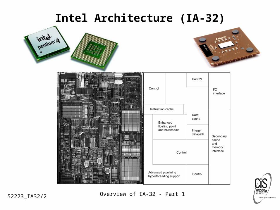
Intel Architecture (IA-32)
52223_IA32/2

Overview of IA-32 - Part 1
IA-32 - A Brief History
The IA-32 architecture family was preceded by 16-bit processors, the 8086 and 8088:• The 16-bit 8086 with 16-bit registers and a 16-bit external data bus, with
(segmented) 20-bit addressing giving a 1-MiB address space.
• The 8088 is similar to the 8086 except it has an 8-bit external data bus.
• The 8086/8088 introduced segmentation to the IA-32 architecture.
• With segmentation, a 16-bit segment register contains a pointer to a memory segment of up to 64 KiB. Using four segment registers at a time, 8086/8088 processors are able to address up to 256 KiB without switching between segments. The 20-bit addresses that can be formed using a segment register and an additional 16-bit pointer provide a total address range of 1 MiB.
52223_IA32/3

Overview of IA-32 - Part 1
…IA-32 - A Brief History
The Intel386 processor was the first 32-bit processor in Intel’s IA-32 architecture family.
It introduced 32-bit registers for use both to hold operands and for addressing. The lower half of each 32-bit Intel386 register retains the properties of the 16-bit registers of earlier generations, permitting backward compatibility.
The Intel386 processor has support for:• A 32-bit address bus that supports up to 4-GiB of physical memory
• A segmented-memory model and a flat memory model
• Paging, with a fixed 4-KiB page size providing a method for virtual memory management
52223_IA32/4

Overview of IA-32 - Part 1
IA-32 Segmented Addressing
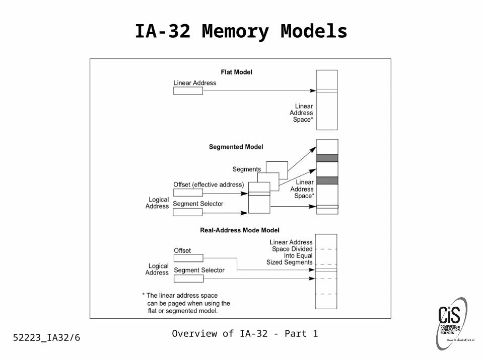
An IA-32 processor uses byte addressing. This means memory is organized and accessed as a sequence of bytes.
The range of memory that can be addressed is called an address space.
The processor also supports segmented addressing - a form of addressing where a program may have many independent address spaces, called segments.
52223_IA32/5
Overview of IA-32 - Part 1
IA-32 Memory Models
52223_IA32/6
Overview of IA-32 - Part 1
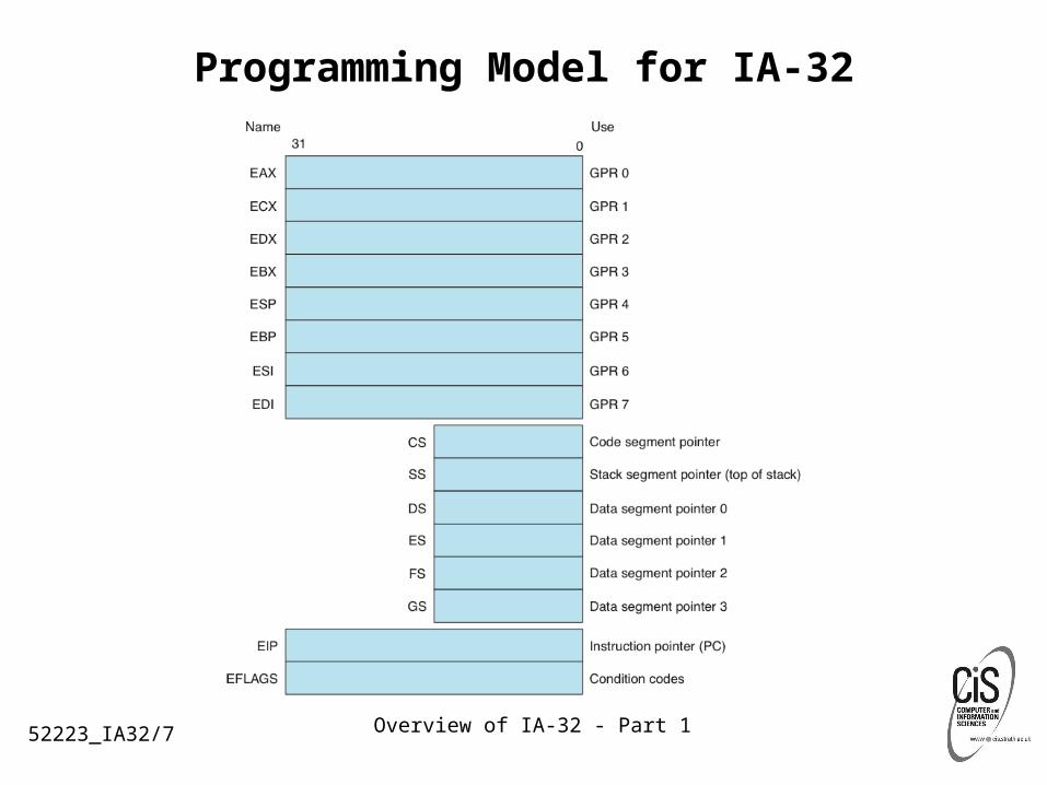
Programming Model for IA-32
52223_IA32/7

Overview of IA-32 - Part 1
Basic Program Execution Registers IA-32 provides 16 basic program execution registers
for use in general system and application programming. These registers can be grouped as follows:• General-purpose registers. These eight registers are
available for storing operands and pointers.• Segment registers. These registers hold up to six segment
selectors.• EFLAGS (program status and control) register. The
EFLAGS register report on the status of the program being executed and allows limited (application-program level) control of the processor.
• EIP (instruction pointer) register. Contains the address (offset) of the instruction to be executed.
52223_IA32/8

Overview of IA-32 - Part 1
General Purpose Registers
The GPRs are provided for holding the following items:• Operands for logical and arithmetic operations• Operands for address calculations• Memory pointers
EAX — Accumulator for operands and results dataEBX — Pointer to data in the DS segmentECX — Counter for string and loop operationsEDX — I/O pointerESI — Pointer to data in the segment pointed to by the DS register; source
pointer for string operationsEDI — Pointer to data (or destination) in the segment pointed to by the ES
register; destination pointer for string operationsESP — Stack pointer (in the SS segment)EBP — Pointer to data on the stack (in the SS segment)
52223_IA32/9
Overview of IA-32 - Part 1
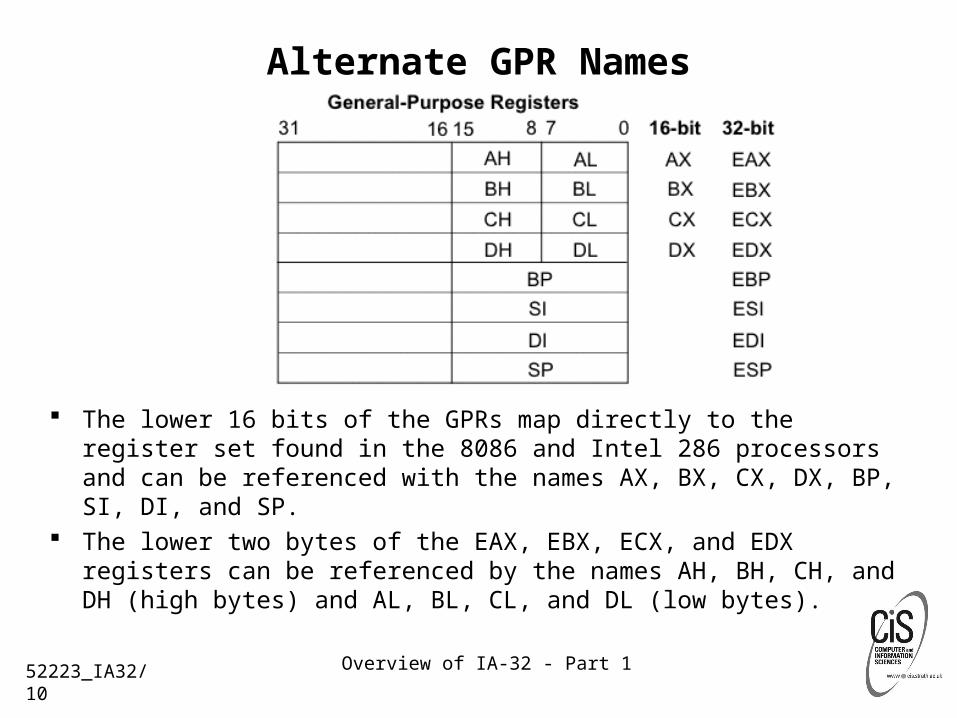
Alternate GPR Names
The lower 16 bits of the GPRs map directly to the register set found in the 8086 and Intel 286 processors and can be referenced with the names AX, BX, CX, DX, BP, SI, DI, and SP.
The lower two bytes of the EAX, EBX, ECX, and EDX registers can be referenced by the names AH, BH, CH, and DH (high bytes) and AL, BL, CL, and DL (low bytes).
52223_IA32/10

Overview of IA-32 - Part 1
Segment Registers
The four segment registers CS, DS, SS, and ES are the same as the segment registers found in the Intel 8086 and Intel 286 processors and the FS and GS registers were introduced into the IA-32 Architecture.
52223_IA32/11
Overview of IA-32 - Part 1
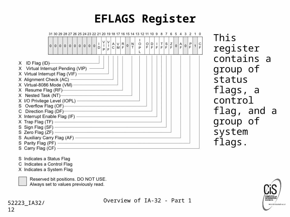
EFLAGS Register
This register contains a group of status flags, a control flag, and a group of system flags.
52223_IA32/12
Overview of IA-32 - Part 1
Status Flags The status flags of the EFLAGS register indicate the
results of arithmetic instructions, such as the ADD, SUB, MUL, and DIV:
• CF (bit 0) Carry flag — Set if an arithmetic operation generates a carry or a borrow out of the most-significant bit of the result; cleared otherwise. Indicates an overflow condition for unsigned-integer arithmetic. Also used in multiple-precision arithmetic.
• PF (bit 2) Parity flag — Set if the least-significant byte of the result contains an even number of 1 bits; cleared otherwise.
• AF (bit 4) Adjust flag — Set if an arithmetic operation generates a carry or a borrow out of bit 3 of the result; cleared otherwise. Used in binary-coded decimal (BCD) arithmetic.
52223_IA32/13
Overview of IA-32 - Part 1
…Status Flags
• ZF (bit 6) Zero flag — Set if the result is zero; cleared otherwise.
• SF (bit 7) Sign flag — Set equal to the most-significant bit of the result, which is the sign bit of a signed integer. (0 indicates a positive value and 1 indicates a negative value.)
• OF (bit 11) Overflow flag — Set if the integer result is too large a positive number or too small a negative number to fit in the destination operand; cleared otherwise. Indicates an overflow condition for signed-integer (two’s complement) arithmetic.
52223_IA32/14
Overview of IA-32 - Part 1
Instruction Pointer
The instruction pointer (EIP) register contains the offset in the current code segment for the next instruction to be executed.
It is advanced from one instruction boundary to the next in straightline code or it is moved ahead or backwards by a number of instructions when executing JMP, Jcc, CALL, RET, and IRET instructions.
52223_IA32/15

Overview of IA-32 - Part 1
Operand Addressing
IA-32 machine-instructions act on zero or more operands. Some operands are specified explicitly and others are implicit. The data for a source operand can be located in:• the instruction itself (an immediate operand)• a register• a memory location• an I/O port
When an instruction returns data to a destination operand, it can be returned to:• a register• a memory location• an I/O port
52223_IA32/16
Overview of IA-32 - Part 1
Immediate Operands
Some instructions use data encoded in the instruction itself as a source operand. These operands are called immediate operands (or simply immediates).
Example: the following ADD instruction adds an immediate value of 14 to the contents of the EAX register:
ADD EAX, 14
52223_IA32/17

Overview of IA-32 - Part 1
Register Operands
Source and destination operands can be any found in the registers, depending on the instruction being executed. These operands are called register operands.
Example: the following ADD instruction adds the contents of the EBX register to the contents of the EAX register:
ADD EAX, EBX
52223_IA32/18

Overview of IA-32 - Part 1
…Register Operands
Some instructions (such as the DIV and MUL instructions) use quadword operands contained in a pair of 32-bit registers.
Register pairs are represented with a colon separating them.• Example: in the register pair EDX:EAX, EDX
contains the high order bits and EAX contains the low order bits of a quadword operand.
52223_IA32/19

Overview of IA-32 - Part 1
Memory Operands
Source and destination operands in memory are referenced by means of a segment selector and an offset.• Segment selectors specify the segment containing the
operand.• Offsets specify the linear or effective address of the operand.• Offsets can be 32 bits (represented by the notation m16:32)
or 16 bits (represented by the notation m16:16).
52223_IA32/20

Overview of IA-32 - Part 1
Specifying a Segment Selector
The segment selector can be specified either implicitly or explicitly.
The most common method of specifying a segment selector is to load it in a segment register and then allow the processor to select the register implicitly, depending on the type of operation being performed.
52223_IA32/21
Overview of IA-32 - Part 1
Segmented Addressing
In IA-32 a program can keep its code and stack in separate segments. Code addresses would always refer to the code space, and stack addresses would always refer to the stack space.
The following notation is used to specify a byte address within a segment: Segment-register:Byte-address• Example 1: The following segment address identifies the
byte at address FF79H in the segment pointed by the DS register:
DS:FF79H• Example 2: The following segment address identifies an
instruction address in the code segment. The CS register points to the code segment and the EIP register contains the address of the instruction:
CS:EIP
52223_IA32/22

Overview of IA-32 - Part 1
Segment Override
When storing data in memory or loading data from memory, the DS segment default can be overridden to allow other segments to be accessed. Within an assembler, the segment override is generally handled with a colon “:” operator.
Example: the following MOV instruction moves a value from register EAX into the segment pointed to by the ES register. The offset into the segment is contained in the EBX register:
MOV ES:[EBX], EAX;
52223_IA32/23
Overview of IA-32 - Part 1
…Segment Override
At the machine level, a segment override is specified with a segment-override prefix, which is a byte placed at the beginning of an instruction. The following default segment selections cannot be overridden:• Instruction fetches must be made from the code
segment.• Destination strings in string instructions must be
stored in the data segment pointed to by the ES register.
• Push and pop operations must always reference the SS segment.
52223_IA32/24
Overview of IA-32 - Part 1
Specifying an Offset
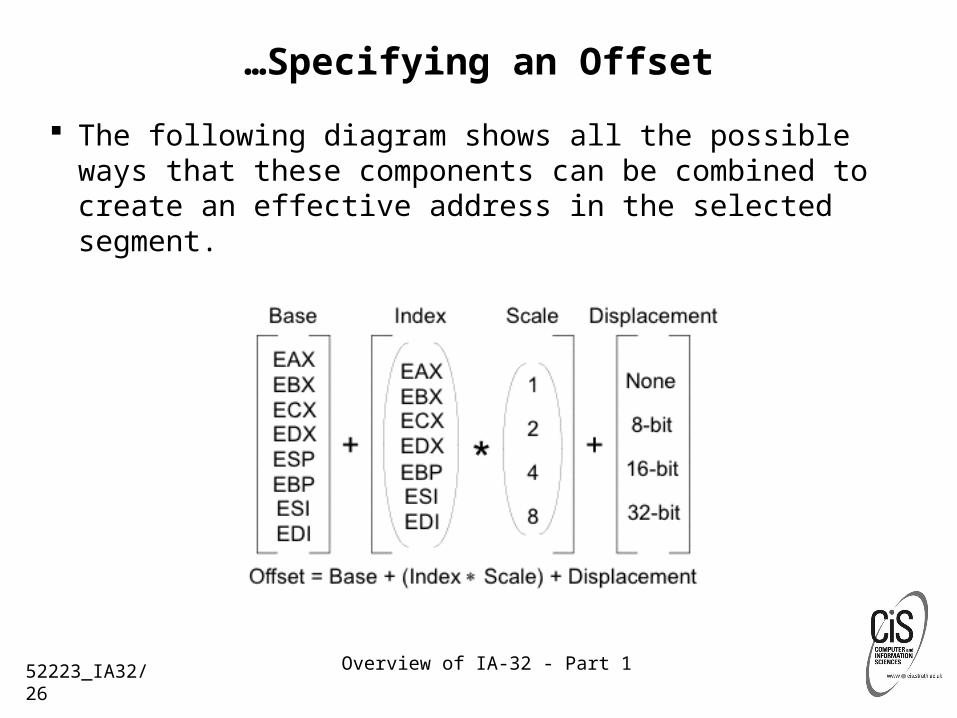
The offset part of a memory address can be specified directly as:• a static value (called a displacement)• or as an address computed from one or more of the
following components: Displacement — An 8-, 16-, or 32-bit value. Base — The value in a general-purpose register. Index — The value in a general-purpose register. Scale factor — A value of 2, 4, or 8 that is multiplied by
the index value. The offset which results from adding these
components is called an effective address.
52223_IA32/25
Overview of IA-32 - Part 1
…Specifying an Offset
The following diagram shows all the possible ways that these components can be combined to create an effective address in the selected segment.
52223_IA32/26
Overview of IA-32 - Part 1
…Specifying an Offset
The uses of general-purpose registers as base or index components are restricted in the following manner:
• The ESP register cannot be used as an index register.
• When the ESP or EBP register is used as the base, the SS segment is the default segment.
In all other cases, the DS segment is the default segment. The base, index, and displacement components can be used in
any combination. A scale factor may be used only when an index also is used. Each possible combination - address mode - is useful for data
structures commonly used by programmers in high-level languages and assembly language.
52223_IA32/27

Overview of IA-32 - Part 1
DisplacementAddress Mode
A displacement alone represents a direct (uncomputed) offset to the operand.
Because the displacement is encoded in the instruction, this form of an address is sometimes called an absolute or static address.
It is commonly used to access a statically allocated scalar operand.
52223_IA32/28
Overview of IA-32 - Part 1
BaseAddress Mode
A base alone represents an indirect offset to the operand.
Since the value in the base register can change, it can be used for dynamic storage of variables and data structures.
52223_IA32/29
Overview of IA-32 - Part 1
Base + DisplacementAddress Mode
A base register and a displacement can be used together for two distinct purposes:• As an index into an array when the element size is not 2, 4,
or 8 bytes The displacement component encodes the static offset to
the beginning of the array. The base register holds the results of a calculation to
determine the offset to a specific element within the array.
• To access a field of a record: The base register holds the address of the beginning of
the record. The displacement is a static offset to the field.
52223_IA32/30

Overview of IA-32 - Part 1
(Index * Scale) + DisplacementAddress Mode
This address mode offers an efficient way to index into a static array when the element size is 2, 4, or 8 bytes.• The displacement locates the beginning of the array.• The index register holds the subscript of the desired
array element.• The processor automatically converts the subscript
into an index by applying the scaling factor.
52223_IA32/31

Overview of IA-32 - Part 1
Base + Index + DisplacementAddress Mode
Using two registers together supports either:• a two-dimensional array (the displacement holds the
address of the beginning of the array) or• one of several instances of an array of records (the
displacement is an offset to a field within the record).
52223_IA32/32

Overview of IA-32 - Part 1
Base + (Index * Scale) + DisplacementAddress Mode
Using all the addressing components together allows efficient indexing of a two-dimensional array when the elements of the array are 2, 4, or 8 bytes in size.
52223_IA32/33
Overview of IA-32 - Part 1
Assembler and Compiler Addressing Modes
At the machine-code level, the selected combination of displacement, base register, index register, and scale factor is encoded in an instruction.
All assemblers permit a programmer to use any of the allowable combinations of these addressing components to address operands.
High-level language compilers will select an appropriate combination of these components based on the language construct a programmer defines.
52223_IA32/34
Overview of IA-32 - Part 1
I/O Port Addressing
An IA-32 processor supports an I/O address space that contains up to 65,536 8-bit I/O ports.
Ports that are 16-bit and 32-bit may also be defined in the I/O address space.
An I/O port can be addressed with either an immediate operand or a value in the DX register.
52223_IA32/35

Overview of IA-32 - Part 152223_IA32/36
Acknowledgements and References
Pentium 4 Manuals<http://support.intel.com/design/pentium4/manuals/index_new.htm>
Pentium 4 Technical Documentation Index<http://support.intel.com/design/Pentium4/documentation.htm>
Intel's Legal Link - T&C and other bits and bobs in their small print
52.223 Low Level Programming Lecturer: Duncan Smeed
Overview of IA-32
Part 2

Overview of IA-32 - Part 2
Fundamental Data Types
The fundamental data types of IA-32 architecture are:• bytes - 8 bits,
• words - 16 bits,
• doublewords - 32 bits,
• quadwords - 64 bits, and
• double quadwords - 128 bits
A subset of the IA-32 architecture instructions operates on these fundamental data types without any additional operand typing.
52223_IA32/38

Overview of IA-32 - Part 2
…Fundamental Data Types
52223_IA32/39

Overview of IA-32 - Part 2
…Fundamental Data Types
Bytes, Words, Doublewords, Quadwords, and Double Quadwords in Memory
52223_IA32/40
Overview of IA-32 - Part 2
Alignment
The natural boundaries for words, double words, and quadwords are even-numbered addresses, addresses evenly divisible by four, and addresses evenly divisible by eight, respectively.
Words, doublewords, and quadwords do not need to be aligned in memory on natural boundaries.
However, to improve the performance of programs, data structures (especially stacks) should be aligned on natural boundaries whenever possible.
52223_IA32/41
Overview of IA-32 - Part 2
Numeric Data Types
Although bytes, words, and doublewords are the fundamental data types of the IA-32 architecture, some instructions support additional interpretations of these data types to allow operations to be performed on numeric data types (signed and unsigned integers, and floating-point numbers).
52223_IA32/42
Overview of IA-32 - Part 2
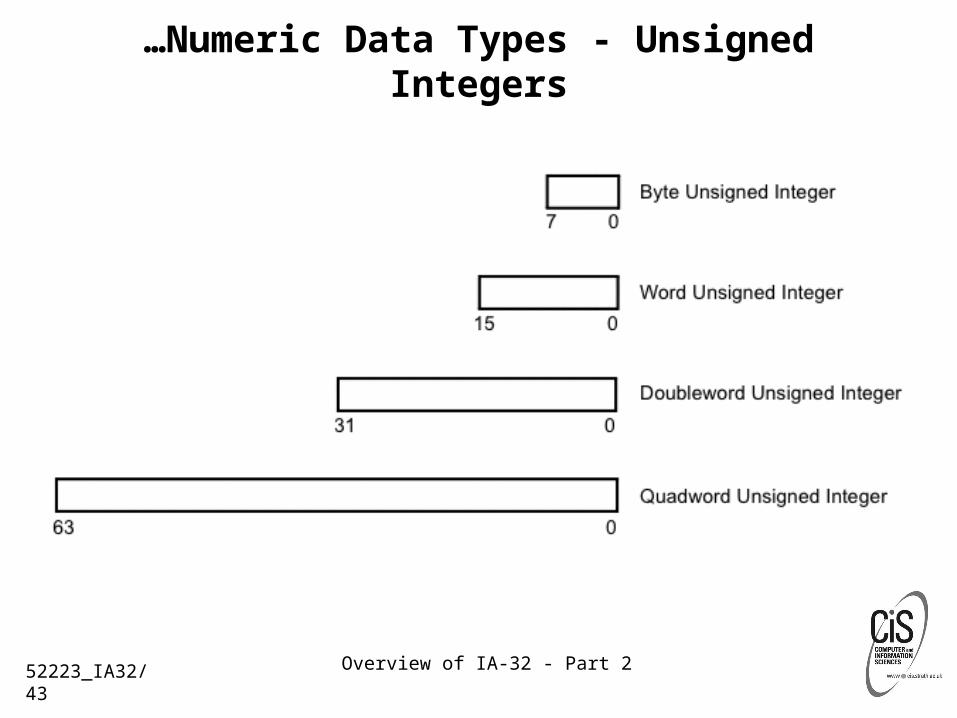
…Numeric Data Types - Unsigned Integers
52223_IA32/43

Overview of IA-32 - Part 2
…Numeric Data Types - Signed Integers
52223_IA32/44

Overview of IA-32 - Part 2
…Numeric Data Types - Floating Point
52223_IA32/45
Overview of IA-32 - Part 2
Pointer Data Types
Pointers are addresses of locations in memory. In IA-32 mode, the architecture defines two types of pointers - a near pointer and a far pointer.
A near pointer is a 32-bit (or 16-bit) offset within a segment. Near pointers are used for all memory references in a flat memory model or for references in a segmented model where the identity of the segment being accessed is implied.
A far pointer is a logical address, consisting of a 16-bit segment selector and a 32-bit (or 16-bit) offset. Far pointers are used for memory references in a segmented memory model where the identity of a segment being accessed must be specified explicitly.
52223_IA32/46

Overview of IA-32 - Part 2
…Pointer Data Types
52223_IA32/47

Overview of IA-32 - Part 2
IA-32 Instruction Format
When instructions are represented symbolically in IA-32 assembly language an instruction has the following format:
label: mnemonic argument1,argument2,argument3
where:• A label is an identifier which is followed by a colon.
• A mnemonic is a reserved name for a class of instruction opcodes which have the same function.
• The operands argument1, argument2, and argument3 are optional.
52223_IA32/48
Overview of IA-32 - Part 2
IA-32 Instruction Operands
There may be from zero to three operands, depending on the opcode. When present, they take the form of either literals or identifiers for data item.
Operand identifiers are either reserved names of registers or are assumed to be assigned to data items declared in another part of the program.
When two operands are present in an arithmetic or logical instruction, the right operand is the source and the left operand is the destination. For example:
LOADREG: MOV EAX, SUBTOTAL In this example, LOADREG is a label, MOV is the mnemonic
identifier of an opcode, EAX is the destination operand, and SUBTOTAL is the source operand.
52223_IA32/49
Overview of IA-32 - Part 2
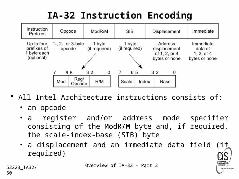
IA-32 Instruction Encoding
All Intel Architecture instructions consists of:
• an opcode
• a register and/or address mode specifier consisting of the ModR/M byte and, if required, the scale-index-base (SIB) byte
• a displacement and an immediate data field (if required)
52223_IA32/50
Overview of IA-32 - Part 2
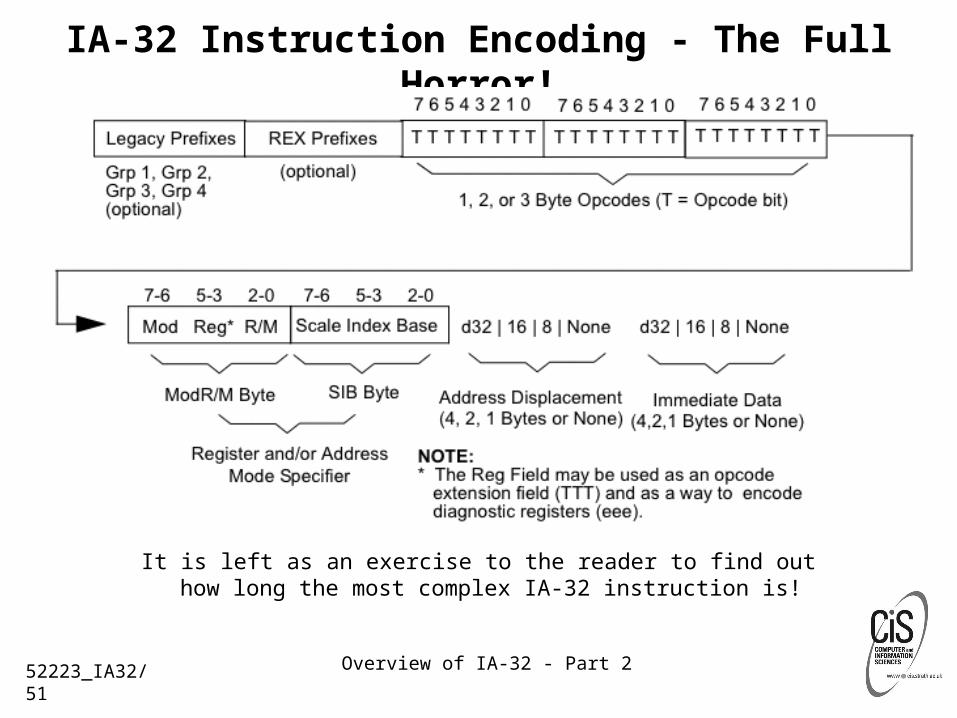
IA-32 Instruction Encoding - The Full Horror!
It is left as an exercise to the reader to find out how long the most complex IA-32 instruction is!
52223_IA32/51

Overview of IA-32 - Part 2
Typical IA-32 Instruction Formats
52223_IA32/52