5.1 lathe - wordpress.com · 2016-11-14 · yforging yextrusion ydrawing terminology semi ... it...
TRANSCRIPT


9/1/2011
1
Metal FormingMetal Forming
By S K Mondal
Four Important forming techniques are:
Rolling
Forging
Extrusion
Drawing
TerminologySemi‐finished product
Bloom: is the product of first breakdown of ingot.
Billet: is the product obtained from a further reduction byp y
hot rolling (cross sectional area > 40 x 40 mm2)
Slab: is the hot rolled ingot (cross sectional area > 100 cm2
and with a width >= 2 x thickness)
Contd.
TerminologyMill product
Plate is the product with thickness > 5 mm
Sheet is the product with thickness < 5 mm and width > 600p 5
mm
Strip is the product with a thickness < 5 mm and width <
600 mm
Plastic DeformationDeformation beyond elastic limits.Due to slip, grain fragmentation, movement of atoms and lattice distortion.
Recrystallisation Temperature (Rx)“The minimum temperature at which the completedrecrystallisation of a cold worked metal occurs within aspecified period of approximately one hour”.Rx decreases strength and increases ductility.If ki b R h t ki hIf working above Rx, hot‐working process whereasworking below are cold‐working process.It involves replacement of cold‐worked structure by anew set of strain‐free, approximately equi‐axed grains toreplace all the deformed crystals. Contd.

9/1/2011
2
Rx depends on the amount of cold work a material has
already received. The higher the cold work, the lower
would be the Rx.
Rx varies between 1/3 to ½ melting paint.
Rx = 0.4 xMelting temp. (Kelvin).
Rx of lead and Tin is below room temp.
Rx of Cadmium and Zinc is room temp.
Rx of Iron is 450oC and for steels around 1000°C
Finer is the initial grain size; lower will be the RxContd.
Grain growthGrain growth follows complete crystallization if the materials left at elevated temperatures.
Grain growth does not need to be preceded by recovery and recrystallization; it may occur in all polycrystalline materials.
In contrary to recovery and recrystallization, driving force for this process is reduction in grain boundary energy.
In practical applications, grain growth is not desirable.
Incorporation of impurity atoms and insoluble second phase particles are effective in retarding grain growth.
Grain growth is very strongly dependent on temperature.
Strain HardeningWhen metal is formed in cold state, there is no
recrystalization of grains and thus recovery from
i di t ti f t ti d t t kgrain distortion or fragmentation does not take
place.
As grain deformation proceeds, greater resistance
to this action results in increased hardness and
strength i.e. strain hardening.
MalleabilityMalleability is the property of a material whereby it can
be shaped when cold by hammering or rolling.
A malleable material is capable of undergoing plastic
deformationwithout fracture.
A malleable material should be plastic but it is not
essential to be so strong.
Lead, soft steel, wrought iron, copper and aluminium are
somematerials in order of diminishing malleability.
Cold WorkingCold WorkingWorking below recrystalization temp.

9/1/2011
3
Advantages of Cold Working1. Better accuracy, closer tolerances
2. Better surface finish
3. Strain hardening increases strength and hardnessg g
4. Grain flow during deformation can cause desirable
directional properties in product
5. No heating of work required (less total energy)
Disadvantages of Cold Working1. Equipment of higher forces and power required
2. Surfaces of starting work piece must be free of scale and
dirt
l d h d l h f f3. Ductility and strain hardening limit the amount of forming
that can be done
4. In some operations, metal must be annealed to allow
further deformation
5. Some metals are simply not ductile enough to be cold
worked.
Hot Working
Working above recrystalization temp.
Advantages of Hot Working1. The porosity of the metal is largely eliminated.2. The grain structure of the metal is refined.3. The impurities like slag are squeezed into fibers anddistributed throughout the metal.4. The mechanical properties such as toughness,ductility, percentage elongation, percentage reduction inarea, and resistance to shock and vibration are improveddue to the refinement of grains.
Dis‐advantages of Hot Working1. It requires expensive tools.2. It produces poor surface finish, due to the rapidoxidation and scale formation on the metal surface.3. Due to the poor surface finish, close tolerancecannot be maintained.

9/1/2011
4
Micro‐Structural Changes in a Hot Working Process (Rolling)
•Annealing relieves the stresses from cold working – threestages: recovery, recrystallization and grain growth.•During recovery, physical properties of the cold‐workedmaterial are restored without any observable change inmicrostructure.
Annealing
Warm FormingDeformation produced at temperatures intermediate to
hot and cold forming is known as warm forming.
Compared to cold forming, it reduces loads, increase
material ductility.
Compared to hot forming, it produce less scaling and
decarburization, better dimensional precision and
smoother surfaces.
Isothermal FormingDuring hot forming, cooler surfaces surround a hotter
interior, and the variations in strength can result in non‐
uniform deformation and cracking of the surface.
For temp sensiti e materials deformation is performedFor temp.‐sensitive materials deformation is performed
under isothermal conditions.
The dies or tooling must be heated to the workpiece
temperature, sacrificing die life for product quality.
Close tolerances, low residual stresses and uniform metal
flow.
IES Made Easy
9/1/2011
1
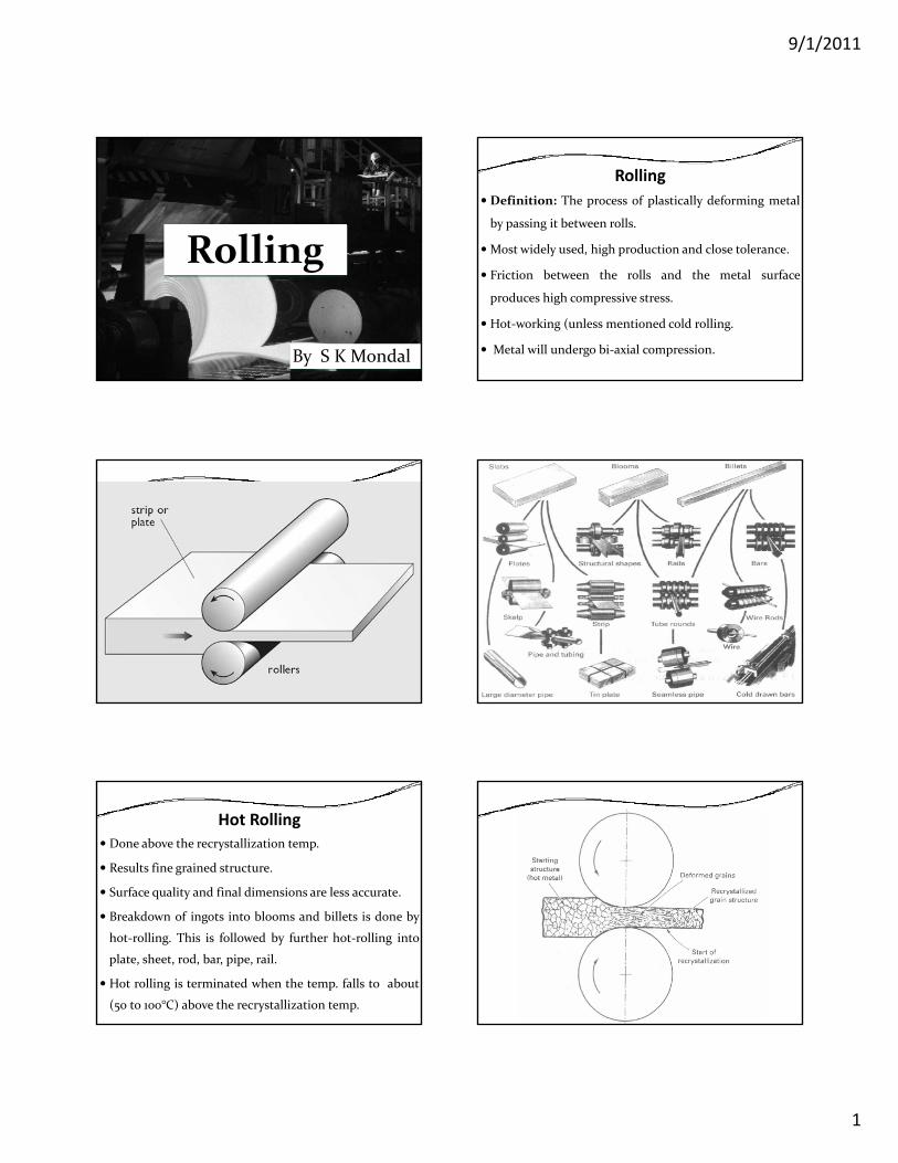
RollingRolling
By S K Mondal
RollingDefinition: The process of plastically deforming metal
by passing it between rolls.
Most widely used, high production and close tolerance.
Friction between the rolls and the metal surface
produces high compressive stress.
Hot‐working (unless mentioned cold rolling.
Metal will undergo bi‐axial compression.
Hot RollingDone above the recrystallization temp.
Results fine grained structure.
Surface quality and final dimensions are less accurate.
Breakdown of ingots into blooms and billets is done by
hot‐rolling. This is followed by further hot‐rolling into
plate, sheet, rod, bar, pipe, rail.
Hot rolling is terminated when the temp. falls to about
(50 to 100°C) above the recrystallization temp.

9/1/2011
2
Cold RollingDone below the recrystallization temp..
Products are sheet, strip, foil etc. with good surface
finish and increased mechanical strength with close
product dimensions.
Performed on four‐high or cluster‐type rolling mills.
(Due to high force and power)
Cold Rolling Contd..Skin‐rolled metal is given only a 0.5% to 1% reduction toproduce a smooth surface and uniform thickness, and toremove the yield‐point phenomenon (i.e., prevent formationof Luders bands upon further forming). This material is wellsuited for subsequent cold‐working operations where goodductility is required.
Quarter‐hard, half‐hard, and full‐hard sheet and strip haveexperienced greater amounts of cold reduction, up to 50%.Consequently, their yield points have been increased,properties have become directional, and ductility hasdecreased. Quarter‐hard steel can be bent back on itselfacross the grain without breaking. Half‐hard and full‐hardcan be bent back 90o and 45o respectively, about a radiusequal to the material thickness.
Assumptions of cold rollingMaterial is plastic.
The arc of contact is circular with a radius greater than
the radius of the roll.
Coefficient of friction is constant over the arc of contact
Ring RollingRing rolls are used for tube rolling, ring rolling.
As the rolls squeeze and rotate, the wall thickness is
reduced and the diameter of the ring increases.
Shaped rolls can be used to produce a wide variety of
cross‐section profiles.
Ring rolls are made of spheroidized graphite bainitic and
pearlitic matrix or alloy cast steel base.

9/1/2011
3
Sheet rollingIn sheet rolling we are only attempting to reduce the
cross section thickness of a material.
Roll Forming
Roll BendingA continuous form of three‐point bending is roll
bending, where plates, sheets, and rolled shapes can
be bent to a desired curvature on forming rolls.g
Upper roll being adjustable to control the degree of
curvature.

9/1/2011
4
Shape rolling Pack rollingPack rolling involves hot rolling multiple sheets of
material at once, such as aluminium foil.
A thin surface oxide film prevents their welding.
Thread rollingUsed to produce threads in substantial quantities.
This is a cold‐forming process in which the threads are
formed by rolling a thread blank between hardened dies
that cause the metal to flow radially into the desired
shape.
No metal is removed, greater strength, smoother, harder,
and more wear‐resistant surface than cut threads.
Thread rolling contd….Major diameter is always greater than the diameter of the
blank (
Blank diameter is little larger than the pitch diameter of
the thread.
Restricted to ductile materials.
Manufacture of gears by rollingThe straight and helical teeth of disc or rod type external
steel gears of small to medium diameter and module are
generated by cold rolling.
High accuracy and surface integrity.
Employed for high productivity and high quality. (costly
machine)
Larger size gears are formed by hot rolling and then
finished by machining.

9/1/2011
5
Fig. Production of teeth of spur gears by rolling
Roll piercing
It is a variation of rolling called roll piercing.The billet or round stock is rolled between two rolls,both of them rotating in the same direction with theiraxes at an angle of 4.5 to 6.5 degree.These rolls have a central cylindrical portion with thesides tapering slightly. There are two small side rolls,hich help in guiding the metalwhich help in guiding the metal.
Because of the angle at which the roll meets the metal,it gets in addition to a rotary motion, an additionalaxial advance, which brings the metal into the rolls.This cross‐rolling action makes the metal friable at thecentre which is then easily pierced and given acylindrical shape by the central‐piercing mandrel.
Planetary millConsist of a pair of heavy backing rolls surrounded by a largenumber of planetary rolls.Each planetary roll gives an almost constant reduction to theslab as it sweeps out a circular path between the backing rollsand the slab.As each pair of planetary rolls ceases to have contact with thep p ywork piece, another pair of rolls makes contact and repeatthat reduction.The overall reduction is the summation of a series of smallreductions by each pair of rolls. Therefore, the planetary millcan not reduce a slab directly to strip in one pass through themill.The operation requires feed rolls to introduce the slab intothe mill, and a pair of planishing rolls on the exit to improvethe surface finish.

9/1/2011
6
Camber
Camber can be used to correct the roll deflection (at onlyone value of the roll force).
Lubrication for RollingHot rolling of ferrous metals is done without a lubricant.
Hot rolling of non‐ferrous metals a wide variety of
compounded oils, emulsions and fatty acids are used.
Cold rolling lubricants are water‐soluble oils, low‐
viscosity lubricants, such as mineral oils, emulsions,
paraffin and fatty acids.
Geometry of Rolling Process DraftTotal reduction or “draft” taken in rolling.
0 fh = h - h = 2 (R - R cos ) = D (1 - cos )Δ α α
Usually, the reduction in blooming mills is about 100 mm and in slabbing mills, about 50 to 60 mm.
Maximum Draft
( ) 2maxhΔ = Rμ
Assumption in Rolling1. Rolls are straight, rigid cylinders.2. Strip is wide compared with its thickness, so that no widening of strip occurs (plane strain conditions).3. The material is rigid perfectly plastic (constant yield t th)strength).4. The co‐efficient of friction is constant over the tool‐work interface.

9/1/2011
7
Torque and PowerThe power is spent principally in four ways1) The energy needed to deform the metal.2) The energy needed to overcome the frictional force.3) The power lost in the pinions and power‐transmissionsystem.4) Electrical losses in the various motors and generators.
Remarks: Losses in the windup reel and uncoiler mustalso be considered.

9/1/2011
1
Forging
By S K Mondal
ForgingBecause of the manipulative ability of the forgingprocess, it is possible to closely control the grain flow inthe specific direction, such that the best mechanicalproperties can be obtained based on the specificapplication.application.
Preparing Metals for Cold WorkingThe starting material must be clean and free of oxide or
scale.
Scale can be removed by acid pickling, in which the
metal is dipped in acid and then washed. In addition,
sheet metal and plate is sometimes given a light cold
rolling prior to the major deformation.
DraftThe draft provided on the sides for withdrawal of theforging.Adequate draft should be provided‐at least 3o foraluminum and 5 to 7o for steel.I t l f i d ft th t lInternal surfaces require more draft than externalsurfaces.
FlashThe excess metal added to the stock to ensure completefilling of the die cavity in the finishing impression iscalled Flash.

9/1/2011
2
Flash Contd…
A flash acts as a cushion for impact blows from thefinishing impression and also helps to restrict theoutward flow of metal, thus helping in filling of thin ribsand bosses in the upper die.The amount of flash depends on the forging size andThe amount of flash depends on the forging size andmay vary from 10 to 50 per cent.The forging load can be decreased by increasing theflash thickness.
GutterIn addition to the flash, provision should be made in thedie for additional space so that any excess metal can flowand help in the complete closing of the die. This is calledgutter.
Gutter Contd….
Without a gutter, a flash may become excessively thick,
not allowing the dies to close completely.
Gutter depth and width should be sufficient to
accommodate the extra, material.
Operations involved in forgingSteps involved in hammer forging Fullering or swagingEdging or rollingBendingDrawing or coggingFlatteningBlocking Finishing operationTrimming or cut off
Fullering or swagingIt is the operation of reducing the stock between the twoends of the stock at a central place, so as to increase itslength.
Fullering or swaging Contd…A forging method for reducing the diameter of a bar andin the process making it longer is termed as Fullering.

9/1/2011
3
Edging or rollingGathers the material as required in the final forging.
The pre‐form shape also helps in proper location of stock
in the blocking impressions.
The area at any cross section should be same as that of
the corresponding section in the component and the
flash allowance.
Edging or rolling Contd….
BendingBending operation makes the longitudinal axis of the
stock in two or more places. This operation is done after
the stock has been edged or fullered and edged so that
the stock is brought into a proper relation with the shape
of the finishing impression.
BlockingImparts to the forging it’s general but not exact or finalshape. This operation is done just prior to finishingoperation.
FlatteningThis operation is used to flatten the stock so that it fitsproperly into the finishing impression of a closed die.
FinishingThe dimensions of the finishing impression are same as
that of the final forging desired with the necessary
allowances and tolerances.
A gutter should be provided in the finishing impression.
9/1/2011
4
Cut‐offA pair of blades used to cut away a forging from the barafter the finishing blow.
Drop ForgingThe drop forging die consists of two halves. The lower
half of the die is fixed to the anvil of the machine, while
the upper half is fixed to the ram. The heated stock is
kept in the lower die while the ram delivers four to five
blows on the metal, in quick succession so that the metal
spreads and completely fills the die cavity. When the two
die halves close, the complete cavity is formed.
Drop forging is used to produce small components.
Press ForgingForce is a continuous squeezing type applied by the
hydraulic presses.
Advantages of Press Forging over Drop Forging
Press forging is faster than drop forging
Alignment of the two die halves can be more easily
maintained than with hammering.
Structural quality of the product is superior to drop
forging.
With ejectors in the top and bottom dies, it is possible to
handle reduced die drafts.
Machine ForgingUnlike the drop or press forging where the material is
drawn out, in machine forging, the material is only upset
to get the desired shape.
Upset ForgingIncreasing the diameter of a material by compressing its
length.
Employs split dies that contain multiple positions or
cavities.

9/1/2011
5
Roll ForgingWhen the rolls are in the open position, the heated stock
is advanced up to a stop. As the rolls rotate, they grip and
roll down the stock. The stock is transferred to a second
set of grooves. The rolls turn again and so on until the
piece is finished.
Roll Forging Contd….A rapid process.
Forging DefectsUnfilled Sections: Die cavity is not
completely filled, due to improper
design of die
Cold Shut or fold: A small crack at
the corners of the forging. Cause:
improper design of the die
Forging Defects Contd….
Scale Pits: Irregular depressions on the surface due toimproper cleaning of the stock.Die Shift: Due to Misalignment of the two die halves ormaking the two halves of the forging to be of impropershapeshape.Flakes: Internal ruptures caused by the impropercooling.Improper Grain Flow: This is caused by the improperdesign of the die, which makes the flow of metal notfollowing the final intended directions.
Forging Defects Contd….
Forging Laps: These are folds of metal squeezed
together during forging. They have irregular contours
and occur at right angles to the direction of metal flow.
Hot tears and thermal cracking: These are surface
cracks occurring due to non‐uniform cooling from the
forging stage or during heat treatment.
Lubrication for ForgingLubricants influence: friction, wear, deforming forces
and flow of material in die‐cavities, non‐sticking,
thermal barrier.
For hot forging: graphite, MoS2 and sometimes molten
glass.
For cold forging: mineral oil and soaps.
In hot forging, the lubricant is applied to the dies, but in
cold forging, it is applied to the workpiece.

9/1/2011
1
ExtrusionExtrusion
By S K Mondal
ExtrusionThe extrusion process is like squeezing toothpaste out ofa tube.
Metal is compressed and forced to flow through a
suitably shaped die to form a product with reduced but
constant cross section.
Metal will undergo tri‐axial compression.
Hot extrusion is commonly employed.
Lead, copper, aluminum, magnesium, and alloys of these
metals are commonly extruded.
Steels, stainless steels, and nickel‐based alloys are
difficult to extrude. (high yield strengths, welding with
wall). Use phosphate‐based and molten glass
lubricants .
Extrusion RatioRatio of the cross‐sectional area of the billet to the cross‐
sectional area of the product.
about 40: 1 for hot extrusion of steel
400: 1 for aluminium
Advantages of ExtrusionAny cross‐sectional shape can be extruded from the
nonferrous metals.
Many shapes (than rolling)
No draft
Huge reduction in cross section.
Conversion from one product to another requires only a
single die change
Good dimensional precision.

9/1/2011
2
Limitation of ExtrusionCross section must be uniform for the entire length of
the product.
ApplicationWorking of poorly plastic and non ferrous metals and
alloys.
Manufacture of sections and pipes of complex
configuration.
Medium and small batch production.
Manufacture of parts of high dimensional accuracy.
Hot Extrusion ProcessThe temperature range for hot extrusion of aluminum is
430‐480°C
Used to produce curtain rods made of aluminum.
Design of die is a problem.
Either direct or indirect method used.
Direct ExtrusionA solid ram drives the entire billet to and through astationary die and must provide additional power toovercome the frictional resistance between the surface of themoving billet and the confining chamber.
Indirect ExtrusionA hollow ram drives the die back through a stationary,confined billet.
Since no relative motion, friction between the billet andthe chamber is eliminated.

9/1/2011
3
Indirect Extrusion Contd…Required force is lower (25 to 30% less)
Low process waste.
Cold ExtrusionUsed with low‐strength metals such as lead, tin, zinc,
and aluminum to produce collapsible tubes for
toothpaste, medications, and other creams; small "cans"
for shielding electronic components and larger cans for
food and beverages.
Now‐a‐days also been used for forming mild steel parts.
Backward cold extrusionThe metal is extruded through the gap between the
punch and die opposite to the punch movement.
For softer materials such as aluminium and its alloys.
Used for making collapsible tubes, cans for liquids and
similar articles.
Impact Extrusion
The extruded parts are stripped by the use of a stripperplate, because they tend to stick to the punch.
Hooker Method Hooker MethodThe ram/punch has a shoulder and acts as a mandrel.A flat blank of specified diameter and thickness is placed in asuitable die and is forced through the opening of the die withthe punchwhen the punch starts downward movement. Pressure is
d b h h ld f h h h l b i f dexerted by the shoulder of the punch, the metal being forcedto flow through the restricted annular space between thepunch and the opening in the bottom of the die.In place of a flat solid blank, a hollow slug can also be used.If the tube sticks to the punch on its upward stroke, astripper will strip it from the punch.Small copper tubes and cartridge cases are extruded by thismethod.

9/1/2011
4
Hydrostatic ExtrusionAnother type of cold extrusion process.
High‐pressure fluid applies the force to the workpiece
through a die.
It is forward extrusion, but the fluid pressure
surrounding the billet prevents upsetting.
Billet‐chamber friction is eliminated, and the
pressurized fluid acts as a lubricant between the billet
and the die.
Hydrostatic Extrusion Contd….
Hydrostatic Extrusion Contd….Temperature is limited since the fluid acts as a heat sinkand the common fluids (light hydrocarbons and oils)burn or decomposes at moderately low temperatures.The metal deformation is performed in a high‐compression environment Crack formation iscompression environment. Crack formation issuppressed, leading to a phenomenon known aspressure‐induced ductility.Relatively brittle materials like cast iron, stainless steel,molybdenum, tungsten and various inter‐metalliccompounds can be plastically deformed withoutfracture, and materials with limited ductility becomehighly plastic.
ApplicationExtrusion of nuclear reactor fuel rod
Cladding of metals
Making wires for less ductile materials
Lubrication for ExtrusionFor hot extrusion glass is an excellent lubricant withsteels, stainless steels and high temperature metals andalloys.For cold extrusion, lubrication is critical, especially withsteels because of the possibility of sticking (seizure)steels, because of the possibility of sticking (seizure)between the workpiece and the tooling if the lubricationbreaks down. Most effective lubricant is a phosphateconversion coating on the workpiece.
Wire DrawingA cold working process to obtain wires from rods of
bigger diameters through a die.
Same process as bar drawing except that it involves
smaller‐diameter material.
At the start of wire drawing, the end of the rod or wire to
be drawn is pointed (by swaging etc.) so that it freely
enters the die orifice and sticks out behind the die.

9/1/2011
5
Wire Drawing Contd…. Wire Drawing Contd….Wire getting continuously wound on the reel.
For fine wire, the material may be passed through a
number of dies, receiving successive reductions in
diameter, before being coiled.
The wire is subjected to tension only. But when it is in
contact with dies then a combination of tensile,
compressive and shear stresses will be there in that
portion only.
Cleaning and Lubrication in wire DrawingCleaning is done to remove scale and rust by acid pickling.
Lubrication boxes precede the individual dies to help reducefriction drag and prevent wear of the dies.
Sulling: The wire is coated with a thin coat of ferroushydroxide which when combined with lime acts as filler forthe lubricant.
Phosphating: A thin film of Mn, Fe or Zn phosphate isapplied on the wire.
Electrolytic coating: For very thin wires, electrolytic coatingof copper is used to reduce friction.
Wire Drawing Die
Die materials: tool steels or tungsten carbides orpolycrystalline diamond (for fine wire)
Rod and Tube DrawingRod drawing is similar to wire drawing except for the factthat the dies are bigger because of the rod size beinglarger than the wire.The tubes are also first pointed and then enteredthrough the die where the point is gripped in a similarthrough the die where the point is gripped in a similarway as the bar drawing and pulled through in the formdesired along a straight line.When the final size is obtained, the tube may beannealed and straightened.The practice of drawing tubes without the help of aninternal mandrel is called tube sinking.
Rod and Tube Drawing Contd…
Tube Sinking Fixed Plug Drawing
Floating plug Drawing Moving Mandrel

9/1/2011
6
Swaging or kneadingThe hammering of a rod or tube to reduce its diameter
where the die itself acts as the hammer.
Repeated blows are delivered from various angles,
causing the metal to flow inward and assume the shape
of the die.
It is cold working. The term swaging is also applied to
processes where material is forced into a confining die to
reduce its diameter.
Swaging or kneading Contd…
Extrusion LoadApproximate method (Uniform deformation, no friction) “work – formula”
ln oo
f
AP AA
σ⎛ ⎞
= ⎜ ⎟⎜ ⎟⎝ ⎠
For real conditions
K = extrusion constant.
f⎝ ⎠
ln oo
f
AP KAA
⎛ ⎞= ⎜ ⎟⎜ ⎟
⎝ ⎠
Force required in Wire or Tube drawing
Approximate method (Uniform deformation, no friction) “work – formula”
A⎛ ⎞ln o
ff
AP AA
σ⎛ ⎞
= ⎜ ⎟⎜ ⎟⎝ ⎠
Wire Drawing
( ) 2 2
1 111 .
B Bo
d bo o
B r rB r r
σσ σ
⎡ ⎤+ ⎛ ⎞ ⎛ ⎞⎢ ⎥= − +⎜ ⎟ ⎜ ⎟⎢ ⎥⎝ ⎠ ⎝ ⎠⎣ ⎦
Maximum Reduction per pass
( ) 2 2
1 1
With back stress,
11 .
b
B Bo
o b
B r rB r r
σ
σσ σ
⎡ ⎤+ ⎛ ⎞ ⎛ ⎞⎢ ⎥= − +⎜ ⎟ ⎜ ⎟⎢ ⎥⎝ ⎠ ⎝ ⎠⎣ ⎦o oB r r⎢ ⎥⎝ ⎠ ⎝ ⎠⎣ ⎦
( ) 2
1
Without back stress,
11
b
Bo
oo
B rB r
σ
σσ
⎡ ⎤+ ⎛ ⎞⎢ ⎥= − ⎜ ⎟⎢ ⎥⎝ ⎠⎣ ⎦