504 873-102/march 2004 - abb ltd installation arc welding system m2001 504 873-102 march 2004 i 1...
TRANSCRIPT

Software InstallationArc Welding System M2001
504 873-102/March 2004


Software Installation
Arc Welding System M2001
504 873-102
Rev. March 2004

The information in this document is subject to change without notice and should be construed as a com-mitment by ABB. ABB assumes no responsibility for any errors that may appear in this document.
In no event shall ABB be liable for damages of any nature from the use of this document.
This document and parts thereof must not be reproduced or copied without ABB´s written permission, and the contents thereof must not be imparted to a third party nor be used for any unauthorized purpose.
Copies of this document can be ordered from ABB.
© ABB Automation Technologies AB
Ordering number: 504 873-102
Date: March 2004
ABB Automation Technologies AB
Arc Welding Products
S-695 82 Laxå
Sweden

Software InstallationArc Welding System M2001
504 873-102 March 2004 i
1 Introduction 1Software 1
General 1Delivered system software 1All installations 2
Upgrading software installations 3General 3Installation of own rapid modules and configuration files 3Signal names 4Modules 4
Installation and configuration 5General 5“Arc Welding System Configuration” Diskette 5Content of the “Arc Welding System Configuration” Diskette 5User´s configuration 6Installation procedure 6
Drive unit 7Combinations and connections 7
2 Booting functions 9General 9
Installation 9From an external PC 9From diskette 9
Change active controller system 10General 10X-start 10Option diskettes 11
RobInstall 12General 12Software key 12Creating a new system 12
Installation example 13Preferences 13Prereferences for Robinstall 14Create a new system 16Add external option 17Information about external option 18Add additional parameter data 19Add options 20

Software InstallationArc Welding System M2001
ii March 2004 504 873-102
Down load Robot controller system 24Backup & Restore 27
General 27
3 System directory structure 29MediaPool 29
General 29New RobotWare 29System 29
4 Arc welding configuration 31Introduction 31
General 31About the ARCITEC arc welding system 31Data structure 31
About the RAPID Converter 32General 32Conversion 32Example: 33

Software Installation IntroductionSoftware
504 873-102 Rev. March 2004 1
1 Introduction
1.1 Software
1.1.1 General
An arc welding system which is delivered by ABB Automation Technologies AB is at delivery booted with a configuration that is customized for the delivery. In most cases there is also a set of software drivers for the equipment loaded. There might still be reasons to use this installation description. Obvious examples are:
• A system is to be installed at the customer site.• The RobotWare software is to be replaced.• The loaded software must be replaced.• The configuration is to be changed.• A stalled system has to be restarted.• To change the language.
1.1.2 Delivered system software
The following software is supplied for the arc welding system:• Diskette Arc Welding System Configuration Diskette, which contains the arc welding
configuration supplied.• CD disk RobotWare• Diskette Manipulator Parameter Disk
Before the installation activity is started, the programmer must read the safety information in the System Manual, section Introduction and safety, chapter Safety.
The diskettes that contain the control program must not be modified in anyway. This can result in the deactivation of safety functions such as reduced speed.

Introduction Software InstallationSoftware
2 Rev. March 2004 504 873-102
1.1.3 All installations
Before the software installation is started:1. Position all robot and positioner axes in their zero positions.2. Write down the commutation and calibration offsets for all motors. Robot and external
axes.3. Save all system parameters, system modules and program modules on diskette.
Alternatively:4. Make a backup of the system, (see User’s Guide for the Robot system).
System parameters that are changed after the booting with the Arc Welding System Configuration Diskette must be saved on your own user diskette

Software Installation IntroductionUpgrading software installations
504 873-102 Rev. March 2004 3
1.2 Upgrading software installations
1.2.1 General
When delivered, the system is installed with configuration files and rapid modules that are adapted to suit the station in question. On certain occasions it may be necessary to add to and modify the rapid modules, for example, when the station is customized. To ensure that everything runs smoothly when a backup copy needs to be restored, it is a good idea to transfer one’s own software to an external optional disk. If this is not done, unnecessarily long operational stoppages can occur.The installation script of the external optional disk is encrypted. To make it possible to install one’s own rapid modules and configuration files, there is a further file, ADDAWOPT.CMD, that should be modified with the addition of one’s own files. See the example below.
1.2.2 Installation of own rapid modules and configuration files
Example ADDAWOPT.CMD:
In the example above, the file copies RAPID.SYS to %HOME%/system/rapid, and loads the file into memory in accordance with the settings in the file RAPID.CFG, which should be created. See the examples below of what this file can look like.Example rapid.cfg:
When the system is started, in this example, the file RAPID.SYS will be loaded and ready to use in the system without having to use manual commands of the type FILE -> Load module. This ensures that the correct things are in memory when a backup is restored and minimizes the risk of mistakes by the operator.
# [File: ADDAWOPT.CMD]# Here you can put aditional options to the option disc# from Laxå. The install file will automatic hook this# file.
copy -from $BOOTPATH/Code/rapid.sys -to system/rapid.sysconfig -filename $BOOTPATH/SYS/rapid.cfg -domain SYS
# [File: rapid.cfg]SYS:CFG_1.0:3:0:
CAB_TASK_MODULES: -File “ram1disk:/system/rapid.sys” -ModName “myMod”

Introduction Software InstallationUpgrading software installations
4 Rev. March 2004 504 873-102
1.2.3 Signal names
All signal names in RAPID programs and system modules must match the signal names in the system parameters. If not, the signal names in the RAPID programs and system modules must be changed. The signal names in the system configuration should not be changed as these are based on a global standard.
1.2.4 Modules
All system modules and program modules that contain Seamdata, Welddata and Weavedata ought to be converted to XRG-format (=> XRG-files).
• The RAPID converter is described in the “S4Cplus User's Guide, System Parameters Process Ware, Arc Welding, Activating arc welding parameters”.

Software Installation IntroductionInstallation and configuration
504 873-102 Rev. March 2004 5
1.3 Installation and configuration
1.3.1 General
See Product Manual IRB XXXX section Installation and Commissioning, chapter Installing the Control Program
1.3.2 “Arc Welding System Configuration” Diskette
An “Arc Welding System Configuration” diskette is enclosed with each system that is delivered by ABB Automation Technologies AB. The name of disc is:
• “3HEA50323088” + revision number.Each Arc Welding System configuration diskette is, when it is manufactured, desig-nated for:
• one particular robot serial number or • one particular license number.
1.3.3 Content of the “Arc Welding System Configuration” Diskette
This diskette contains only options acc. to specification.For example:
• I/O-board options. • Addresses and names for all user signals needed for the delivered system.• Configuration options for positioners in the delivered system.• Configuration for arc process equipment in the delivered system.• Configuration options for delivered sensors. • Default configuration options for welding functions.
See section 4.1.2 About the ARCITEC arc welding system.• Drivers, where appropriate, for positioner, operators panel and safety.
It is not authorized to be used in any other robot system than that printed on the diskette label.
Introduction Software InstallationInstallation and configuration
6 Rev. March 2004 504 873-102
1.3.4 User´s configuration
In cases where there are complementary requirements, it is recommended to use make a new one and, add or change configuration components, and save the lot on a user´s configuration diskette. See Chapter 4 Arc welding configuration.
1.3.5 Installation procedure
As mentioned in ABB Robotics manuals the pc application RobInstall is used to create and download systems to the controller.When a system is created or updated the external option can be added. The way to do it is described in Chapter 2 Booting functions.

Software Installation IntroductionDrive unit
504 873-102 Rev. March 2004 7
1.4 Drive unit
1.4.1 Combinations and connections
The table below specifies to which axis computers the selectable drive unit combi-nations shall be connected.
Combinations Type Axis computer Art.number 1
1. The corresponding article numbers can be seen on the respective drive units in the control cabinet.
Positioner type
397 Ext. Axes DC4U Prepared Drives
DC4U Prepared Drives
2 DSQC 358G IRBP L/T, RTT
397 Ext. Axes DC4U + GU DC4U 2 DSQC 358G IRBP A/B/D/K/R; IRBP L/T+RTT
GU 2 DSQC 346U
Introduction Software InstallationDrive unit
8 Rev. March 2004 504 873-102

Software Installation Booting functionsGeneral
504 873-102 Rev. March 2004 9
2 Booting functions
2.1 General
2.1.1 Installation
The installation of the robot software is done:• From an external PC. • From a diskette (the robot controller need to bee equipped with a diskette drive).
2.1.2 From an external PC
The application handling the booting of the RobotWare is called RobInstall. There are two ways to establish connection with the robot:
• The robots are connected to a local network (the LAN output on the robot) making it possible to run RobInstall to come into contact with the hard disk of the robots from a PC connected to the same network. This is applicable when there is more than one robot at the same place.
• From a computer with direct connection to the service output of the robot network.
2.1.3 From diskette
If the robot is equipped with a diskette drive (optional), the robot control system can be transferred using a diskette. The diskette is created in the application RobInstall. Read more about how to create a diskette in the robot product manual, Transferring the robot system via diskettes.

Booting functions Software InstallationChange active controller system
10 Rev. March 2004 504 873-102
2.2 Change active controller system
2.2.1 General
A restart must be implemented to be able to load new software. X-START is described in the case below. This means that one can change the active control sys-tem, see section 2.2.2 X-start.An X-start will exit the running system, store system data on the mass storage mem-ory, and then execute the BootImage to present the Start window. Any system stored in the mass storage memory, may then be selected.When X-start is executed, all the saved system data is reset (in a similar way as with a warm start):
2.2.2 X-start
Action Illustration/Info
1. Click on the “Misc” button and select the ”Service” window”.
Button Misc:
xx0100000194
2. Select “Restart” in the File menu.3. Write the figures: 1_5_9 (the fifth function key is
changed to X-START) 4. Press X-START.
The system is restarted and the ”Start window” is opened.

Software Installation Booting functionsChange active controller system
504 873-102 Rev. March 2004 11
2.2.3 Option diskettes
The option diskettes required to load ATAW’s configurations and software are sys-tem/station specific. The diskettes are used as storage media. The option diskettes are created by ABB Automation Technologies AB. Drivers for calibrating and executing positioners, BullsEye, Tool Service Center, and SmarTac are loaded automatically using an option diskette(s).

Booting functions Software InstallationRobInstall
12 Rev. March 2004 504 873-102
2.3 RobInstall
2.3.1 General
Robinstall is used to create and install the controller software in the S4Cplus robotcontroller. With RobInstall, you can:
• Create a new system• Update an existing system• Down load a system to the controller using Ethernet connection• Create Boot Disks to transfer the system to the Controller
2.3.2 Software key
In order to block the software and make it possible to boot only the options paid for, a special key in the form of a character string is used. The key is supplied with each robot. (This key replaces the keydisc used in S4C systems.)This key is only to be found on the RobotWare CD supplied with each robot.
2.3.3 Creating a new system
Questions during the booting, are now replied to in RobInstall. Also our SEFAX_A option disk is transferred to the system by way of RobInstall.The following data are needed to create a new system:
• Robot serial number• Key for software
• diskette with manipulator parameters1
• diskette “ATAW’s options disk”• type of DC link, i.e. type of rectifier and drive unit.
1. CalibData shall be loaded, which should usually be done.
Software Installation Booting functionsInstallation example
504 873-102 Rev. March 2004 13
2.4 Installation example
2.4.1 Preferences
Before creating a new system use the “Preferences” function to import the Arc Welding External Option disc delivered with the system.
• The name of options is "3HEA50323088." + the revision number.

Booting functions Software InstallationInstallation example
14 Rev. March 2004 504 873-102
2.4.2 Prereferences for Robinstall
The following instructions are an example of an update of system software.
Action Illustration/Info
1. Check that Robinstall is installed. If this is not the case, install it in accordance with the instructions in section ”Installing RobotWare in the computer”.
2. Click the start button on your PC and select Program/ABB Robotics/RobInstall/RobInstall.
The RobInstall start window will open, see following picture.
3. Click the “Preferences” button, see pos. 1.
Start window
4. Click the “Import Program” button, see pos. 2.
All the programs available (RobotWare and options) will be displayed in the next menu.
Create new system.
1
2
Software Installation Booting functionsInstallation example
504 873-102 Rev. March 2004 15
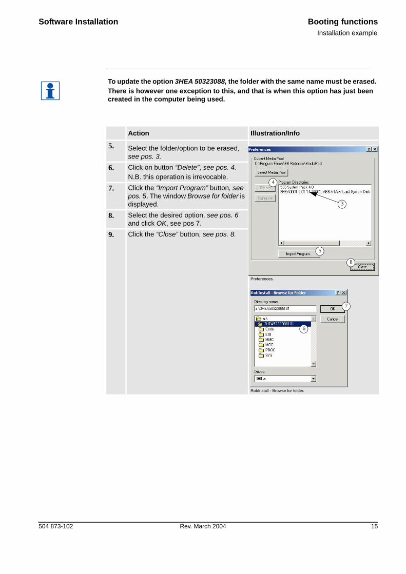
To update the option 3HEA 50323088, the folder with the same name must be erased.There is however one exception to this, and that is when this option has just been created in the computer being used.
Action Illustration/Info
5. Select the folder/option to be erased, see pos. 3.
Preferences.
RobInstall - Browse for folder.
6. Click on button “Delete”, see pos. 4.N.B. this operation is irrevocable.
7. Click the “Import Program” button, see pos. 5. The window Browse for folder is displayed.
8. Select the desired option, see pos. 6 and click OK, see pos 7.
9. Click the “Close” button, see pos. 8.
4
5
3
8
6
7
Booting functions Software InstallationInstallation example
16 Rev. March 2004 504 873-102
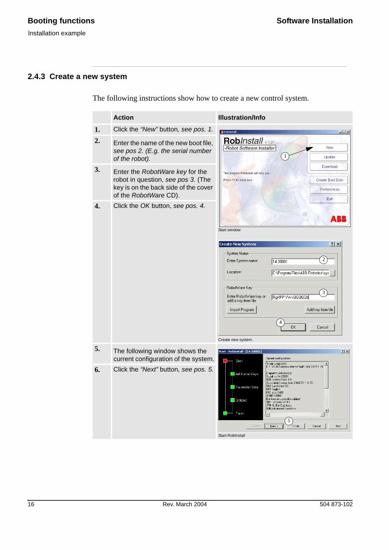
2.4.3 Create a new system
The following instructions show how to create a new control system.
Action Illustration/Info
1. Click the “New” button, see pos. 1.
Start window
Create new system.
2. Enter the name of the new boot file, see pos 2. (E.g. the serial number of the robot).
3. Enter the RobotWare key for the robot in question, see pos 3. (The key is on the back side of the cover of the RobotWare CD).
4. Click the OK button, see pos. 4.
5. The following window shows the current configuration of the system.
Start-RobInstall
6. Click the “Next” button, see pos. 5.
1
2
3
4
5

Software Installation Booting functionsInstallation example
504 873-102 Rev. March 2004 17
2.4.4 Add external option
The following instructions show how to add and external option.
Action Illustration/Info
1. Click the “Add key from file” button, see pos. 1.
Additional Keys_1.
1
The key must be fetched from the media pool that Robinstall uses, which is normally:
• c:\program\Abb robotics\ mediapool\ 3HEA503230880\ extkey.kxt or c:\program files\ abb robotics\ mediapool\ 3HEA503230880\extkey.kxt.
2. Select the file and click the “Open” button, see pos 2.
Additional Keys_2.
3. Select the external option, see pos, 3 and click the “Next” button, see pos 4.
Additional Keys_3
2
3
4

Booting functions Software InstallationInstallation example
18 Rev. March 2004 504 873-102
2.4.5 Information about external option
You can now see that an external option called 3HEA503230880 has been entered into the system. In the 3HEA503230880 option you can also see the number of the program and which robot the option is created for. It can look as follows:
• 3HEA503230880 EO 3HEA0001-0.09 14-00000, Laxå ArcWelding Option.
After booting, this information can be obtained via the TP function, Misc\ Service\ View\ System Info\ Product ID.
Text Indicates
3HEA503230880 The name of the optionEO shows an external option (not ATRO)3HEA0001-0.093 The number and revision of the option14-00000 The number of the robot the option was created forLaxå ArcWelding Option The text only tells us it is an AW option
Software Installation Booting functionsInstallation example
504 873-102 Rev. March 2004 19
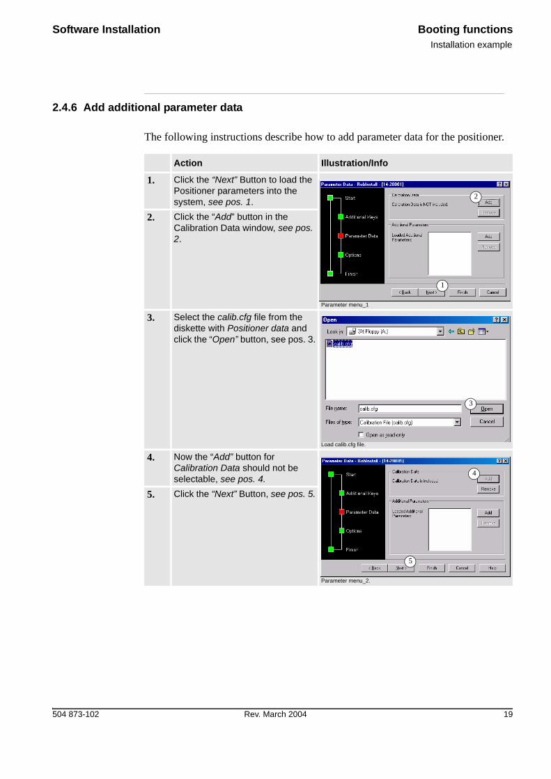
2.4.6 Add additional parameter data
The following instructions describe how to add parameter data for the positioner.
Action Illustration/Info
1. Click the “Next” Button to load the Positioner parameters into the system, see pos. 1.
Parameter menu_1
2. Click the “Add” button in the Calibration Data window, see pos. 2.
3. Select the calib.cfg file from the diskette with Positioner data and click the “Open” button, see pos. 3.
Load calib.cfg file.
4. Now the “Add” button for Calibration Data should not be selectable, see pos. 4.
Parameter menu_2.
5. Click the “Next” Button, see pos. 5.
1
2
3
4
5
Booting functions Software InstallationInstallation example
20 Rev. March 2004 504 873-102
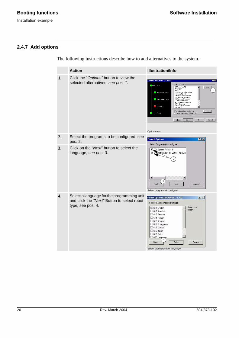
2.4.7 Add options
The following instructions describe how to add alternatives to the system.
Action Illustration/Info
1. Click the “Options” button to view the selected alternatives, see pos. 1.
Option menu.
2. Select the programs to be configured, see pos. 2.
Select program tol configure.
3. Click on the “Next” button to select the language, see pos. 3.
4. Select a language for the programming unit and click the "Next" Button to select robot type, see pos. 4.
Select teach pendant language.
1
2
3
4

Software Installation Booting functionsInstallation example
504 873-102 Rev. March 2004 21
5. Select a manipulator type and click the “Next” button to select external axis, see pos. 5.
Select manipulator variant.
6. Select the chosen external axis and click on the “Next” button to select the type of drive unit, see pos. 6.
Select externa axes.
7. Select the chosen drive unit type for the control cabinet and click on the “Next” button to select the type of drive unit in the external cabinet, see pos. 7. For more information about drive units, see section 1.4.1 Combinations and connections
Select external axes in controller cabinet.
8. Select the chosen drive unit type for the external cabinet and click on the “Next” button to select the BaseWare alternative, see pos. 8.
Select external axers in drive cabinet.
Action Illustration/Info
5
6
7
8

Booting functions Software InstallationInstallation example
22 Rev. March 2004 504 873-102
9. Select the chosen alternative/options and click on the “Next” button if the ArcWare alternative is to be loaded, see pos. 9.
Select generic software options.
10. Select the alternative and click on the “Next” button if the Arcitec alternative is to be loaded, see pos. 10.
Select ArcWare options
11. Select the alternative and click on the “Next” button if the Extended Motion Parameters are to be loaded, see pos. 11.
Select options (Arcitec).
12. Select the alternative and click on the “Next” button to view a summary of the selected alternatives, see pos. 12.
Select extended motion parameters.
Action Illustration/Info
9
10
11
12

Software Installation Booting functionsInstallation example
504 873-102 Rev. March 2004 23
Check that the selections displayed in the window are correct (see the illustration below). It should be noted that the appearance of the display can vary depending on the contents of the key.
Action Illustration/Info
13. Click the “Finish” button to confirm the selection of the alternatives, see pos. 13.Click the “Cancel” button to terminate the selection of the alternatives, see pos. 14.
Select options.
13 14
To allow certain drive units to be made available for selection, it may be necessary to use the Query Mode, see pos. 15 in the illustration below.
14. Click the “Next” Button to finish the configuration, see pos. 16.
Options
15. Now the configuration is finished and a summary is displayed. Click on the “Finish” button and the system will be generated, see pos. 17.
Finish system
16
15
17

Booting functions Software InstallationInstallation example
24 Rev. March 2004 504 873-102
2.4.8 Down load Robot controller system
The following instructions describe the uploading sequence with RobInst.
!It is quite possible to start the download to the wrong robot if the wrong number has been indicated in the target system. This means that it is possible to boot someone else’s system.
Before starting to down load, make sure there are at least 25 Mb free disk space on the controller mass storage memory. For information on how to perform a manual storage capacity check, see section 6.3.1.
Action Illustration/Info
1. Start RobInstall, see section 2.4.3 Create a new system
2. Click the “Download” button, see pos.1.
RobInstall - start
1
Software Installation Booting functionsInstallation example
504 873-102 Rev. March 2004 25
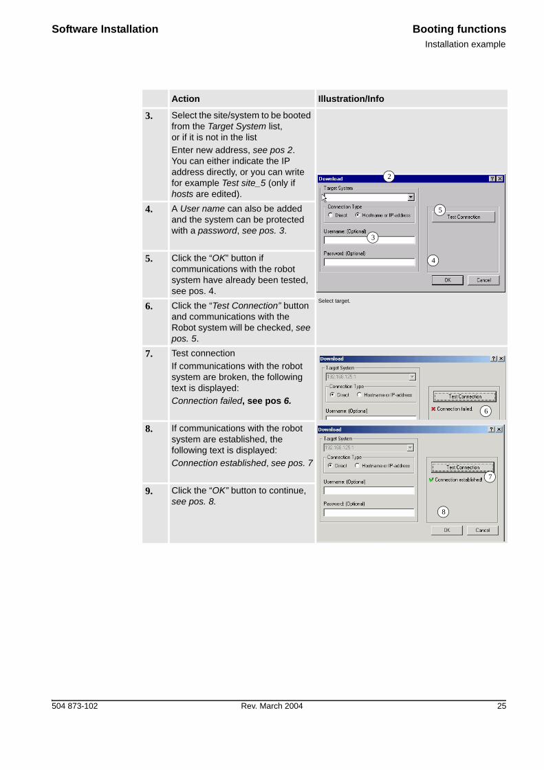
3. Select the site/system to be booted from the Target System list,or if it is not in the list Enter new address, see pos 2.You can either indicate the IP address directly, or you can write for example Test site_5 (only if hosts are edited).
Select target.
4. A User name can also be added and the system can be protected with a password, see pos. 3.
5. Click the “OK” button if communications with the robot system have already been tested, see pos. 4.
6. Click the “Test Connection” button and communications with the Robot system will be checked, see pos. 5.
7. Test connectionIf communications with the robot system are broken, the following text is displayed:Connection failed, see pos 6.
8. If communications with the robot system are established, the following text is displayed:Connection established, see pos. 7
9. Click the “OK” button to continue, see pos. 8.
Action Illustration/Info
2
3
5
4
6
7
8

Booting functions Software InstallationInstallation example
26 Rev. March 2004 504 873-102
10. Select which system to upload, see pos. 9. Click the “OK” button, see pos. 10, to start booting.
Select system.
11. RobInstall now creates a system file and downloads it to the control unit, see pos. 11.
It should be noted that the downloading can take a few minutes.
12. When the download is finished, you can restart the control unit with the new control system.Select YES, see pos. 12.
Action Illustration/Info
9
10

Software Installation Booting functionsBackup & Restore
504 873-102 Rev. March 2004 27
2.5 Backup & Restore
2.5.1 General
Backup is primarily intended for making backup copies of the welding programs and not of the application software. The application software should be booted according to the instructions in section 1.2 Upgrading software installations.When the installation is finished and the welding programs have been created, we recommend that a backup safety copy of the system is made so that it is easy to restore the system in the event of a fault. When changes are made to the system, it is a good idea to make a backup safety copy so that the current safety copy always reflects the latest status of the station.

Booting functions Software InstallationBackup & Restore
28 Rev. March 2004 504 873-102

Software Installation System directory structureMediaPool
504 873-102 Rev. March 2004 29
3 System directory structure
3.1 MediaPool
3.1.1 General
RobInstall uses a directory called MediaPool for storing all the different programs/options available. The MediaPool usually used is found under:
• c:\”’Program’ or ‘Program Files’”\ABB Robotics\MediaPool.When a program is imported by way of Import Program the new program will auto-matically be stored in this file. See Product Manual for Robot Controller, System directory structure for more information.
3.1.2 New RobotWare
When a new RobotWare is released from ATRO it is to be entered under the Media Pool used. The new version will then automatically be used when creating a new system.This can be done in two different ways:
1. Reinstalling RobInstall including RobotWare In this way you will get the new release of both the RobInstall and RobotWare systems.
2. Copying the new RobotWare release over to the Media Pool.
3.1.3 System
When a new system is created it will be stored in the System file under:• c:\’Program’ or ‘Program Files’\ABB Robotics\System\+”name of system”.
To prevent the file gradually getting too big it is advisable to eliminate items now and then. See Installation manual for the robot for more information.

System directory structure Software InstallationMediaPool
30 Rev. March 2004 504 873-102

Software Installation Arc welding configurationIntroduction
504 873-102 Rev. March 2004 31
4 Arc welding configuration
4.1 Introduction
4.1.1 General
This chapter is intended to give the user some hints regarding arc welding configu-ration. The default configuration AW FUNC and AW EQUIP are obtained by the boot sequence as described in chapter Software.The user can then change the configuration in order to meet individual requirements.
• The generic S4C AW process parameters are described in User’s Guide/System Param-eters Process Ware/Arc Welding.
• It is recommended to save this user configuration on a separate User Configuration disk.
4.1.2 About the ARCITEC arc welding system
There are a few arc welding functions that can be controlled by the ArcWare soft-ware or by the power source software. These functions are:
• Ignition• Burnback• Craterfill
The power source functions are to be thought of as first choice since they are easiest to program and more pre-programmed for specified purposes. They are pre-pro-grammed as synergic relationships, which affects the static working point as well as dynamic behavior.See section Programming manual for Arcitec in this binder for more information.
4.1.3 Data structure
The structure of seam data, weld data and weave data must be matching the current arc weld configuration. This will always be the case when the data are created in current (=active) configuration. If required, convert Seam data, Weld data and Weave data in system modules and program modules.The tool for data converting is described in sektion 4.2 About the RAPID Converter.

Arc welding configuration Software InstallationAbout the RAPID Converter
32 Rev. March 2004 504 873-102
4.2 About the RAPID Converter
4.2.1 General
The number of components in the ArcWeld data (seam data, weld data and weave data) is a function of the current configuration.The RAPID converter is a tool to prepare a RAPID program in the current configu-ration for later use and later also make it usable again in any configuration.
4.2.2 Conversion
The conversion consists of following steps:
Action Illustration/Info
1. The RAPID program is saved on diskette.
(Program/File/Save [As]) in the original configuration.
2. Draw up an XRG file from the PRG file in its original configuration.An XRG file is made from this PRG file, still in the original configuration.
(Miscellaneous/FileManager/Options/RAPID Converters.../Add RAPID Type Info...)(Miscellaneous/FileManager/Options/RAPID Converters.../Add RAPID Type Info...)
3. Restore a PRG file (functioning RAPID program) from the XRG file in all future configurations.
(Miscellaneous/FileManager/ Options/RAPID Converters.../Use RAPID Type Info...)
4. Convert AW data in the system modules in a similar way.
SYS file -> (Add) -> XYS file -> (Use) -> SYS file.
It is not always necessary to convert the AW data from one configuration to another. When opening a program (Program/File/Open), mismatching AW data in the program to open is always pointed out.It is of course always possible to convert the data manually in a PC editor.
Make a practice of saving a XRG version of any RAPID program that includes AW data when an 'ordinary' saving (Program/File/Save [As]) is done.Besides a conversion step (=step 2 above), this gives You a way to interpret the components in the AW data. The current structures of seam data, weld data and weave data with its component identifiers are listed in the XRG file.

Software Installation Arc welding configurationAbout the RAPID Converter
504 873-102 Rev. March 2004 33
4.2.3 Example:
If You are unsure of the components in the AW data types when a new configuration is done:
Action Illustration/Info
1. Make a simple help program in the TP, e.g. one ArcL instruction only.
For the sake of simplicity, accept the proposed names sm1, wd1 and wv1 and let all zero-components remain!
2. Save this program, then make a XRG file and look at its AW data structure!
This would be useful when You are going to convert manually to current AW data structures.

Arc welding configuration Software InstallationAbout the RAPID Converter
34 Rev. March 2004 504 873-102


504 873-102/Rev. March 2004