5 system diagrams - vaillantelearning.vaillant.com/.../documents/uk/infopool/system_diagrams.pdf ·...
TRANSCRIPT

No r
esponsib
ility
is taken f
or
the c
orr
ectn
ess a
nd c
om
ple
teness o
f th
is in
form
atio
n -
Date
05/2
015
System diagrams
Online training multiMATIC 700
No r
esponsib
ility
is taken f
or
the c
orr
ectn
ess a
nd c
om
ple
teness o
f th
is in
form
atio
n -
Date
05/2
015
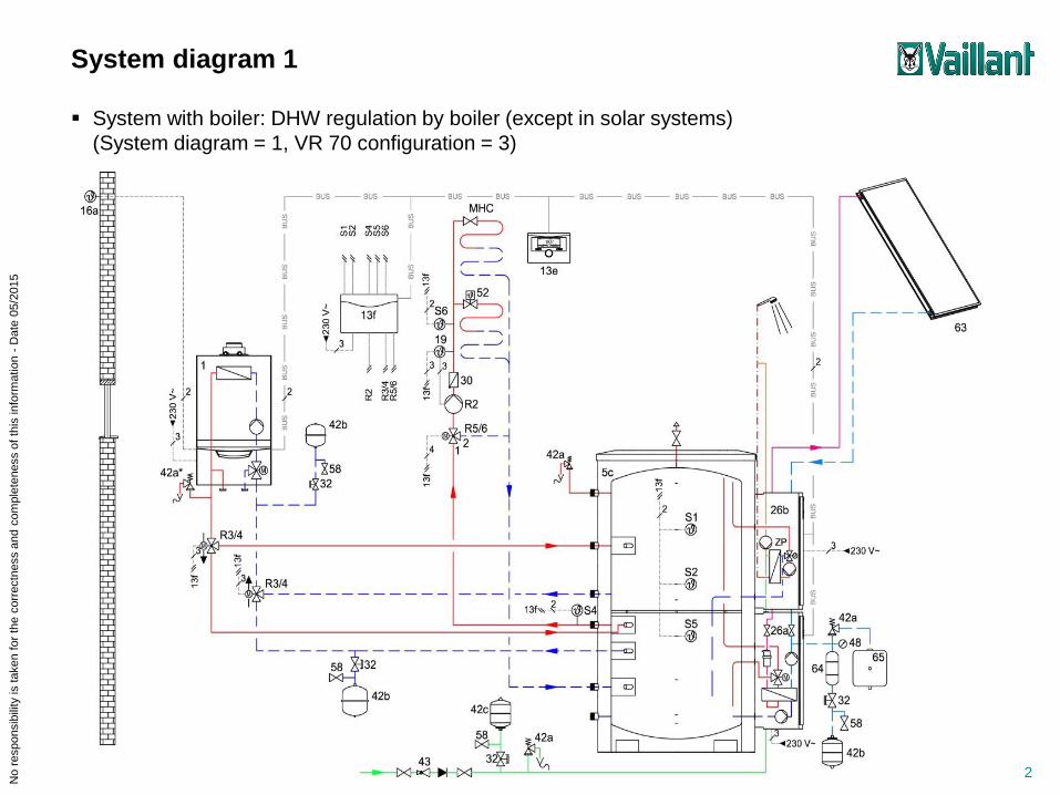
System diagram 1
System with boiler: DHW regulation by boiler (except in solar systems)
(System diagram = 1, VR 70 configuration = 3)
2

No r
esponsib
ility
is taken f
or
the c
orr
ectn
ess a
nd c
om
ple
teness o
f th
is in
form
atio
n -
Date
05/2
015
System with boiler: DHW regulation by VRC 700
(System diagram = 2, VR 70 configuration = 1)
3
System diagram 2

No r
esponsib
ility
is taken f
or
the c
orr
ectn
ess a
nd c
om
ple
teness o
f th
is in
form
atio
n -
Date
05/2
015
3 kW hybrid system (alternative operation mode): DHW only by boiler
(System diagram = 6, no VR 70)
4
System diagram 6

No r
esponsib
ility
is taken f
or
the c
orr
ectn
ess a
nd c
om
ple
teness o
f th
is in
form
atio
n -
Date
05/2
015
3 kW hybrid system (parallel operation mode with 2 circuits / zones): DHW only by boiler
(System diagram = 7, VR 70 configuration = 1)
5
System diagram 7

No r
esponsib
ility
is taken f
or
the c
orr
ectn
ess a
nd c
om
ple
teness o
f th
is in
form
atio
n -
Date
05/2
015
Standard heat pump system, auxiliary heater requires pump of heat pump, monoenergy (DHW by heat
pump and auxiliary heater or simple hybrid system (DHW by boiler only)
(System diagram = 8, no VR 70)
6
System diagram 8

No r
esponsib
ility
is taken f
or
the c
orr
ectn
ess a
nd c
om
ple
teness o
f th
is in
form
atio
n -
Date
05/2
015
Simple hybrid system, auxiliary heater does not require pump of heat pump, DHW by boiler only
(System diagram = 9, VR 70 configuration = 5)
7
System diagram 9
No r
esponsib
ility
is taken f
or
the c
orr
ectn
ess a
nd c
om
ple
teness o
f th
is in
form
atio
n -
Date
05/2
015
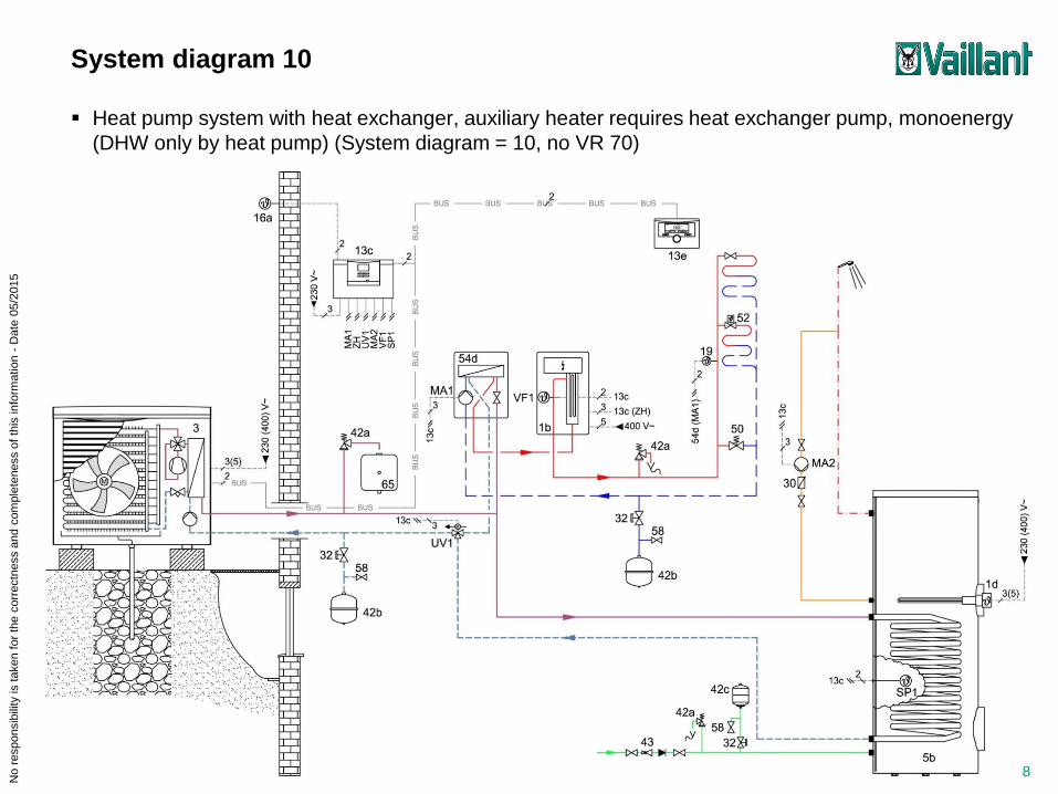
Heat pump system with heat exchanger, auxiliary heater requires heat exchanger pump, monoenergy
(DHW only by heat pump) (System diagram = 10, no VR 70)
8
System diagram 10

No r
esponsib
ility
is taken f
or
the c
orr
ectn
ess a
nd c
om
ple
teness o
f th
is in
form
atio
n -
Date
05/2
015
Standard heat pump system with heat exchanger, auxiliary heater requires pump of heat pump, mono-
energy (DHW by heat pump and auxiliary heater) (System diagram = 11, no VR 70)
9
System diagram 11

No r
esponsib
ility
is taken f
or
the c
orr
ectn
ess a
nd c
om
ple
teness o
f th
is in
form
atio
n -
Date
05/2
015
Complete hybrid system, auxiliary heater does not require pump of heat pump (DHW by heat pump and
boiler) (System diagram = 12, VR 70 configuration = 5)
10
System diagram 12

No r
esponsib
ility
is taken f
or
the c
orr
ectn
ess a
nd c
om
ple
teness o
f th
is in
form
atio
n -
Date
05/2
015
Complete hybrid system with heat exchanger, auxiliary heater does not require pump of heat pump
(DHW by heat pump and boiler) (System diagram = 13, VR 70 configuration = 1)
11
System diagram 13
No r
esponsib
ility
is taken f
or
the c
orr
ectn
ess a
nd c
om
ple
teness o
f th
is in
form
atio
n -
Date
05/2
015
12
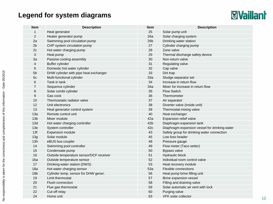
Item Description Item Description
1 Heat generator 25 Solar pump unit
2 Heater generator pump 26a Solar charging system
2a Swimming pool circulation pump 26b Drinking water station
2b CHP system circulation pump 27 Cylinder charging pump
2c Hot water charging pump 28 Zone valve
3 Heat pump 29 Thermal discharge safety device
3a Passive cooling assembly 30 Non-return valve
4 Buffer cylinder 31 Regulating valve
5 Domestic hot water cylinder 32 Cap valve
5b DHW cylinder with pipe heat exchanger 33 Dirt trap
5c Multi-functional cylinder 33a Sludge separator set
6 Tank in tank 34 Increase in return flow
7 Sequence cylinder 34a Mixer for increase in return flow
8 Solar combi cylinder 35 Flow Switch
9 Gas cock 36 Thermometer
10 Thermostatic radiator valve 37 Air separator
12 Unit electronics 38 Diverter valve (inside unit)
13 Heat generator control system 39 Thermostat mixing valve
13a Remote control unit 40 Heat exchanger
13b Mixer module 42a Expansion relief valve
13d Hot water charging controller 42b Diaphragm expansion tank
13e System controller 42c Diaphragm expansion vessel for drinking water
13f Expansion module 43 Safety group for drinking water connection
13g Solar module 45 Low loss header
13h eBUS bus coupler 48 Pressure gauge
14 Swimming pool controller 49 Flow meter (Taco setter)
15 Condensate pump 50 Bypass valve
16 Outside temperature sensor/DCF receiver 51 Hydraulic block
16a Outside temperature sensor 52 Individual room control valve
17 Drinking water station (DWS) 53 Heat recovery module
18a Hot water charging sensor 53a Flexible connections
18b Cylinder temp. sensor for DHW gener. 56 Heat pump brine filling unit
19 Limit thermostat 57 Brine expansion vessel
20 Flush connection 58 Filling and draining valve
21 Flue gas thermostat 59 Solar automatic air vent with lock
22 Cut-off relay 60 Purging valve
24 Home unit 63 VFK solar collector
Legend for system diagrams

No r
esponsib
ility
is taken f
or
the c
orr
ectn
ess a
nd c
om
ple
teness o
f th
is in
form
atio
n -
Date
05/2
015
13
Item Description
63a VTK solar collector
64 Solar in-line vessel
65 Collecting container
66 Pump, cooling circuit
67 3-way mixer
67a 3-way mixer, cooling
67b 3-way mixer, passive cooling assembly
68 Fan coil convector
69 Tundish
70 Air collector
71 VWL 10/3 SA outer unit
72 Suction well pump
84 Swimming pool
93 Compact buffer cylinder
R1 Pump
R2 Pump
R3/R4 Mixer/Pump/Valve
R5/R6 Mixer/Valve
S1 Cylinder/solar temperature sensor/DJ-sensor
S2 Cylinder/solar temperature sensor/DJ-sensor
S3 Cylinder/solar temperature sensor/DJ-sensor
S4 Flow temperature sensor/DJ-sensor
S5 Flow temperature sensor/DJ-sensor
S6 Flow temperature sensor/DJ-sensor
S7 PWM signal
Legend for system diagrams
Drinking water
Domestic hot water
Circulation
Wiring
Heating flow
Heating return
Solar flow
Solar return
Heat source flow
Heat source return
Cooling flow
Cooling return