5-securing the switches.pdf
TRANSCRIPT

The Bryant Advantage CCNP SWITCH Study Guide
Chris Bryant, CCIE #12933 www.thebryantadvantage.com Back To Index
Securing The Switches
Bulldogs,
I've included a bonus section on AAA in this book - please read that along
Passwords
Port Security
Dot1x Port-Based Authentication
SPAN Basics
Local SPAN
Remote SPAN
SPAN Limitations
VLAN Access Control Lists
Private VLANs
DHCP Snooping
Dynamic ARP Inspection
IP Source Guard
MAC Address Flooding
Dealing With Your Clients In The Real World
with this section. Thanks! -- Chris B.
When we think of network security, we tend to focus on protecting our network from attacks originating outside the network.
That's half the battle - but it's important to remember that many successful network attacks are launched from the inside, and from some seemingly innocent sources, such as...
DHCP
ARP
Rogue switches (Switches acting as part of our network, but under the administrative control of a potential network attacker)
CDP
Telnet
Unauthorized MAC addresses
Hosts on the same VLAN (!)
So while it's wise to protect our network from the outside, we better take some measures to protect us from.. the enemy within.
(Cue dramatic music.)
Seriously, we've got some important work to do here - so let's get to it.
The first methods of security I'm going to talk about in this chapter aren't fancy, they aren't exciting, and they don't cost an arm and a leg. But the basic security features are the ones to start with, and I use a four-step approach to basic network security:
1. Physical security - lock those servers, routers, and switches up! This is the most basic form of network security, and it's also the most ignored.
2. Passwords - set 'em, change 'em on occasion. If you're relatively new to a particular job site, be ready for a fight on this point from other admins.

3. Different privilege levels - not every user needs the same level of access to potentially destructive commands, because not every user can handle the responsibility.
4. Grant remote access only to those who absolutely, positively need it -- and when users do connect remotely, make that communication as secure as possible.
Physical security is just that. Get the routers and switches locked up!
Steps two and three go hand in hand, and much of what follows may be familiar to you. Don't skip this part, though, because we're going to tie in privilege levels when it comes to telnet access.
You know how to configure the basic passwords on a switch:
SW2(config)#enable password ccna SW2(config)#enable secret ccnp
SW2(config)#line con 0 SW2(config-line)#login % Login disabled on line 0, until 'password' is set SW2(config-line)#password ccie
SW2(config)#line vty 0 15 SW2(config-line)#password cisco SW2(config-line)#login
Here's a quick refresher on some basic Cisco password rules and messages....
All passwords appear in the configuration in clear text by default except the enable secret. The command service password-encryption will encrypt the remaining passwords.
The login message shown when the login command is used in the above example simply means that a password needs to be set to enable this feature. As long as you enter both the login and password commands, it does not matter in what order you enter them.
Cisco switches have more VTY lines than routers. Routers allow up to five simultaneous Telnet sessions, and obviously switches allow more! The default behavior is the same, however. Any user who telnets in to the switch will be placed into user exec mode, and will then be prompted for the proper enable mode password.

If neither the enable secret nor the enable password has been set, the user will not be able to enter enable mode.
To place users coming into the switch via telnet straight into enable mode, use the command privilege level 15 under the VTY lines.
SW2(config-line)#privilege level 15
Note below how the configuration appears on the switch when it comes to the VTY lines. If you want a command to be applied to all 16 lines, you don't have to use "line vty 0 4" and then "line vty 5 15" - just run the command line vty 0 15.
line vty 0 4 privilege level 15 password cisco login line vty 5 15 privilege level 15 password cisco login
The possible issue here is that any user who telnets in will be placed into enable mode.
It's easy to configure, but maybe we don't want to give that high level of access so easily.
Consider a situation where a tech support person has to telnet into a router. Maybe they know what they're doing, and with all due respect, maybe they don't. Do you want this person making changes to the router without you knowing about it? It may be better to assign privilege level 15 to yourself while assigning the default value of 0 to others.
I also don't like having one password for all telnet users. I prefer a scheme where each individual user has their own password.
Creating a local database of users and privilege levels allows us to do this, and it's a simple procedure. As a matter of fact, you already did this at least once during your CCNA studies. All you have to do is create a username / password database the same way you create one for PPP authentication.
SW2(config)#username CBRYANT privilege 15 password CCIE SW2(config)#username WMCDANIEL password CCNP SW2(config)#username BMULLIGAN password CCNA

SW2(config)#line vty 0 15 SW2(config-line)#login local
The username / password command allows the assignment of privilege levels. If none is specified, level 0 is the default. With the above configuration, the first user would be placed into privileged exec mode when connecting via telnet, while the other two users would be required to enter the enable password before they could enter that mode.
The login local command is required to have the switch look to a local database for authentication information. If a user doesn't know their username/password combination, they can't telnet into this switch.
Port Security
Here's another basic security feature that's regularly overlooked, but is very powerful. Port security uses a host's MAC address as a password...
... and if the port receiving this frame is running port security and expects frames with that particular MAC address only, frames from this host would be accepted.
However, if a device with a different MAC address sends frames to the switch on that port, the port will take action - by default, it will shut down and go into error-disabled state. By default, that state requires manual intervention on the part of the network admin to reopen the port.
The switchport port-security command enables this feature, and then we have quite a few options to consider.
SW2(config)#int fast 0/5 SW2(config-if)#switchport port-security Command rejected: Fa0/5 is not an access port. SW2(config-if)#switchport mode access SW2(config-if)#switchport access vlan 10
Before we can consider the options, we have to make the port in question

a non-trunking port. Port security can't be configured on a port that even has a possibility of becoming a trunk port. Configuring a port as an access port is the equivalent of turning trunking to "off".
Now, let's get back to those options!
SW2(config-if)#switchport port-security ? aging Port-security aging commands mac-address Secure mac address maximum Max secure addresses violation Security violation mode <cr>
The first option to consider is the maximum value. This is the maximum number of secure MAC addresses allowed on the port. This number can vary - I've seen Cisco switches that would allow up to 1024, but this 2950 will only allow 132. These addresses can be configured statically with the mac-address option, they can be learned dynamically, or you can allow a port to do both. (More on that in just a moment.)
SW2(config-if)#switchport port-security maximum ? <1-132> Maximum addresses
SW2(config-if)#switchport port-security mac-address ? H.H.H 48 bit mac address
Now we need to decide the action the port should take in case frames with a non-secure MAC address arrive on the port.
The default port security mode is shutdown, and it's just what it sounds like - the port is placed into error-disabled state and manual intervention is needed to reopen the port. An SNMP trap message is also generated.
(You can also use the errdisable recovery command to specify how long the port should remain in that state before the switch itself resets the port.)
SW2(config-if)#switchport port-security violation ? protect Security violation protect mode restrict Security violation restrict mode shutdown Security violation shutdown mode
Protect mode simply drops the offending frames. Restrict mode is our middle ground - this mode drops the offending frames and will generate both an SNMP trap notification and syslog message regarding the violation, but the port does not go into err-disabled state.

Before we continue, a note of caution - throughout this course, you'll see ports shut down for one reason or another, particularly in the Advanced STP section. Note that not all of these features force the port into err-disabled mode. Be sure you're very familiar with the different states these ports are put into. (I'll have a chart at the end of that section listing each port state.)
Let's take a look at the console messages you'll see when running port security in its default mode, shutdown. I configured a port on this switch with port security, one secure MAC address, and made sure it didn't match the host that would be sending frames on that port. Sure enough, within seconds all of this happened:
SW1(config-if)# 05:06:04: %PM-4-ERR_DISABLE: psecure- violation error detected on Fa0/7, puttingFa0/7 in err-disable state 05:06:04: %PORT_SECURITY-2- PSECURE_VIOLATION: Security violation occurred, caused by MAC address 000f.f773.ed20 on port FastEt hernet0/7. 05:06:05: %LINEPROTO-5- UPDOWN: Line protocol on Interface FastEthernet0/7, changed state to down 05:06:06: %LINK-3-UPDOWN: Interface FastEthernet0/7 , changed state to down
show interface verifies that this interface is in error-disabled state.
SW1#show int fast 0/7 FastEthernet0/7 is down, line protocol is down (err-disabled)
That port must now manually be reopened - of course, after resolving the security issue that brought it down in the first place!
There is a little "gotcha" with port security that you need to be aware of. You can specify the number of secure MAC addresses, and you can specify secure MAC addresses as well. What if you allow for more secure MAC address than you actually configure manually, as shown below?
SW1(config-if)#switchport port-security SW1(config-if)#switchport port-security maximum 3 SW1(config-if)#switchport port-security mac-address aaaa.aaaa.aaaa SW1(config-if)#switchport port-security mac-address cccc.cccc.cccc
In this situation, the remaining secure MAC address will be dynamically learned - so if a rogue host with the MAC address dddd.dddd.dddd connected to that port right now, port security would allow it. Be careful!
In that configuration, these three addresses would be considered secure:

aa-aa-aa-aa-aa-aa
cc-cc-cc-cc-cc-cc
The next dynamically learned MAC address
There is no penalty for hitting the limit of secure addresses - it just means the switch can't learn any more secure addresses.
To verify your port security configuration, run show port-security interface.
SW1#show port-security interface fast 0/2 Port Security : Enabled Port Status : Secure-up Violation Mode : Shutdown Aging Time : 0 mins Aging Type : Absolute SecureStatic Address Aging : Disabled Maximum MAC Addresses : 3 Total MAC Addresses : 2 Configured MAC Addresses : 2 Sticky MAC Addresses : 0 Last Source Address:Vlan : 0000.0000.0000:0 Security Violation Count : 0
The violation mode here is the default, shutdown. In this scenario, the port will be shut down if the number of secure MAC addresses is reached anda host whose MAC address is not among those secure addresses connects to this port.
Note that "aging time" is set to zero - that actually means that secure MAC addresses on this port will never age out, not that they have zero minutes before aging out. You can change this value with the switchport port-security aging command. This particular switch accepts the value set in minutes; many older models want this entered in seconds. Always use IOS Help to double-check a command's metric!
SW1(config-if)#switchport port-security aging time ? <1-1440> Aging time in minutes. Enter a value be tween 1 and 1440
The aging type value determines whether a secure MAC address will absolutely expire after a certain amount of time, or whether aging should be based on inactivity ... as IOS Help shows us!
SW1(config-if)#switchport port-security aging type ? absolute Absolute aging (default) inactivity Aging based on inactivity time period

Port security is a great feature, but you can't run it on all ports. There are a few port types that you can't configure with port security:
� trunk ports � ports placed in an Etherchannel � destination SPAN port � 802.1x ports
Why Make Addresses "Sticky"?
We know a MAC address can be dynamically learned by the switch as secure, and we may want that address marked as secure in the running configuration. To do so, enable sticky learning with this command:
switchport port-security mac-address sticky
Why use sticky addresses? Along with MAC address flooding, network intruders can use a spoofed MAC address to gain access to the network. By configuring sticky learning, the dynamically learned secure MAC addresses are written to the running configuration, which in turn helps to prevent unauthorized network access via MAC spoofing.
Note: To save these dynamically learned static addresses to the startup configuration, you'll need to copy the run config over the startup config before reloading the switch.
Dot1x Port-Based Authentication
Port security is good, but we can take it a step further with dot1x port-based authentication. The name refers to IEEE 802.1x, the standard upon which this feature is based. Unusually enough, the Cisco authentication server must be RADIUS - you can't use TACACS or TACACS+.
One major difference between dot1x port-based authentication and port security is that both the host and switch port must be configured for 802.1x EAPOL (Extensible Authentication Protocol over LANs). That's a major departure from many of the switch features we've studied to date, since most other switch features don't require anything of the host. Usually the PC isn't aware of what the switch is doing, and doesn't need to know. Not this time!

Keeping those rules in mind, a typical dot1x deployment involves:
A dot1x-enabled PC, the supplicant
A dot1x-enabled switch, the authenticator
A RADIUS server, the authentication server (You cannot use a TACACS+ server for this purpose.)
But it's not quite as simple as that. (You were waiting for that, right?)
The PC has a single physical port connected to the switch, but that physical port is logically divided into two ports by dot1x - the controlled and uncontrolled ports.
Unlike the subinterfaces you've studied and created to date, you and I as the network admins do not have to configure the controlled and uncontrolled ports. Dot1x will take care of that - of course, as long as we remember to configure the supplicant for dot1x to begin with!
The controlled port cannot transmit data until authentication actually takes place. The uncontrolled port can transmit without authentication, but only the following protocols can be transmitted:
Extensible Authentication Protocol over LANs (EAPOL)
Spanning Tree Protocol (STP)
Cisco Discovery Protocol (CDP)
By default, once the user authenticates, all traffic can be received and transmitted through this port.
To configure dot1x, AAA must first be enabled. As with previous configurations, a method list must be created. And again, as with previous configurations, you should use line as the last choice, just in case something happens regarding your login with the other methods.
SW2(config)#aaa new-model SW2(config)#aaa authentication dot1x ? WORD Named authentication list. default The default authentication list.
SW2(config)#aaa authentication dot1x default ? enable Use enable password for authenticatio n. group Use Server-group line Use line password for authentication. local Use local username authentication. local-case Use case-sensitive local username aut hentication. none NO authentication.
To enable dot1x on the switch:
SW2(config)#dot1x ? system-auth-control Enable or Disable SysAuthCon trol
Dot1x must be configured globally, but every switch port that's going to run dot1x authentication must be configured as well.
SW2(config-if)#dot1x port-control ? auto PortState will be set to AUTO force-authorized PortState set to Authorized force-unauthorized PortState will be set to UnAu thorized
Force-authorized, the default, does just what it sounds like - it forces the port to authorize any host attempting to use the port, but authentication is not required. Basically, there is no authentication on this port type.
A port in force-unauthorized state literally has the port unable to authorize any client - even clients who could otherwise successfully authenticate!
The auto setting enables dot1x on the port, which will begin the process as unauthorized. Only the necessary EAPOL frames will be sent and received while the port's unauthorized. Once the authentication is complete, normal transmission and receiving can begin. Not surprisingly, this is the most common setting.
SPAN Operation And Configuration
We've secured the ports, but there will also come a time when we want to connect a network analyzer to a switch port. A common situation is illustrated below, where we want to analyze traffic sourced from the three PCs. To properly analyze the traffic, the network analyzer needs a copy of every frame the hosts are sending - but how are we going to get it

there?
SPAN allows the switch to mirror the traffic from the source port(s) to the destination port to which the network analyzer is attached. (In some Cisco documentation, the destination port is referred to as the monitor port.)
SPAN works very well, and the basic operation is simple. Studying SPAN for exams and network usage can seem complicated at first, though, because there are several different versions of SPAN.
The versions are much the same, though; the real difference comes in when you define the source ports. It's the location of the source ports that determines the SPAN version that needs to run on the switch.
In the above example, we're running Local SPAN, since the destination and source ports are all on the same switch. If the source was a VLAN rather than a collection of physical ports, VLAN-based SPAN (VSPAN) would be in effect.
The command monitor session starts a SPAN session, along with allowing the configuration of the source and destination. The sessions are totally separate operations, but the number of simultaneous sessions you can run differs from one switch platform to another. Cat 3550s and
2950s support only two, but more powerful switches can run as many as 64 sessions at once.
SW2(config)#monitor session ? <1-2> SPAN session number
SW2(config)#monitor session 1 ? destination SPAN destination interface or VLAN source SPAN source interface, VLAN
SW2(config)#monitor session 1 source ? interface SPAN source interface remote SPAN source Remote
SW2(config)#monitor session 1 source interface ? FastEthernet FastEthernet IEEE 802.3 Port-channel Ethernet Channel of interfaces
SW2(config)#monitor session 1 source interface fast 0/1 - 5 , Specify another range of interfaces - Specify a range of interfaces both Monitor received and transmitted traffic rx Monitor received traffic only tx Monitor transmitted traffic only <cr>
Here, ports fast 0/1 - 0/5 have been configured as the source. By default, traffic being received and transmitted will be mirrored, but this can be changed to received traffic only and transmitted traffic only as shown above.
Using the same session number, the traffic will be mirrored to the destination port 0/10. Verify the SPAN configuration with show monitor.
SW2(config)#monitor session 1 destination interface fast 0/10
SW2#show monitor Session 1 --------- Type : Local Session Source Ports : Both : Fa0/1-2 Destination Ports : Fa0/10 Encapsulation : Native Ingress: Disabled
SPAN works fine if the source and destination ports are on the same switch, but realistically, that's not always going to happen. What if the traffic to be monitored is on one switch, but the only vacant port available is on another switch?

Remote SPAN (RSPAN) is the solution. Both switches will need to be configured for RSPAN, since the switch connected to the PCs will need to send mirrored frames across the trunk. A separate VLAN will be created that will carry only the mirrored frames.
RSPAN configuration is simple, but there are some factors you need to consider when configuring RSPAN:
� If there were intermediate switches between the two shown in the above example, they would all need to be RSPAN-capable.
� VTP treats the RSPAN VLAN like any other VLAN. It will be propagated throughout the VTP domain if configured on a VTP server. Otherwise, it's got to be manually configured on every switch along the intermediate path. VTP Pruning will also prune the RSPAN VLAN under the same circumstances that it would prune a "normal" VLAN.
� MAC address learning is disabled for the RSPAN VLAN.
� The source and destination must be defined on both the switch with the source port and the switch connected to the network analyzer, but the commands are not the same on each.

After all that, the configuration is simple! Create the VLAN first, and identify it as the RSPAN VLAN with the remote-span command.
SW2(config)#vlan 30 SW2(config-vlan)#remote-span
SW2 is the source switch, and the traffic from ports 0/1 - 0/5 will be monitored and frames mirrored to SW1 via RSPAN VLAN 30.
SW2(config)#monitor session 1 source interface fast 0/1 - 5
SW2(config)#monitor session 1 destination remote ? vlan Remote SPAN destination RSPAN VLAN
SW2(config)#monitor session 1 destination remote vl an 30 % Incomplete command.
SW2(config)#monitor session 1 destination remote vl an 30 ? reflector-port Remote SPAN reflector port
As you see, naming the RSPAN VLAN here doesn't finish the job. We now have to define the reflector port, the port that will be copying the SPAN traffic onto the VLAN.
SW2(config)#monitor session 1 desti remote vlan 30 reflector- port fast 0/12
SW1 will receive the mirrored traffic and will send it to a network analyzer on port 0/10.
SW1(config)#monitor session 1 source remote vlan 30 SW1(config)#monitor session 1 destination interface fast 0/10
Run show monitor to verify the configuration.
SW1#show monitor Session 1 --------- Type : Remote Destination Session Source RSPAN VLAN: 30 Destination Ports : Fa0/10 Encapsulation : Native Ingress: Disabled
SPAN Limitations
As I mentioned, SPAN is easy to configure, but it does have a few
limitations on what ports can be made source or destination ports:
Source port notes:
� A source port can be monitored in multiple, simultaneous SPAN sessions.
� A source port can be part of an Etherchannel. � A source port cannot be configured as a destination port. � A source port can be any port type - Ethernet, FastEthernet, etc.
Destination port notes:
� A destination port can be any port type. � A destination port can participate in only one SPAN session. � A destination port cannot be a source port. � A destination port cannot be part of an Etherchannel. � A destination port doesn't participate in STP, CDP, VTP, PaGP,
LACP, or DTP.
Trunk ports can be configured as source and/or destination SPAN ports; the default behavior will result in the monitoring of all active VLANs on the trunk.
I strongly recommend that you find the SPAN documentation for your switch models before configuring them. SPAN operation is simple, but the command options do change.
Finally, you may see the term "ESPAN" in some SPAN documentation. This is Enhanced SPAN, and some of Cisco's documentation mentions that this term has been used so often to describe different additions that the term has lost meaning. You'll still see it occasionally, but it doesn't refer to any specific addition or change to SPAN.
Filtering Intra-VLAN Traffic
At this point in your Cisco studies, you're very familiar with access lists and their many, many, many uses! Access lists do have their limitations, though. While an ACL can filter traffic traveling between VLANs, it can't do anything about traffic from one host in a VLAN to another host in the same VLAN.
Why not? It relates to how ACLs are applied on a multilayer switch. You know that the CAM (Content Addressable Memory) table holds the MAC

addresses that the switch has learned, but the TCAM - Ternary Content Addressable Memory - cuts down on the number of lookups required to compare a packet against an ACL.
This filtering of packets by the switch hardware speeds up the process, but this limits ACL capability. An ACL can be used to filter inter-VLAN traffic, but not intra-VLAN traffic. To filter traffic between hosts in the same VLAN, we've got to use a VLAN Access List (VACL).
Even though a VACL will do the actual filtering, an ACL has to be written as well. The ACL will be used to as the match criterion within the VACL. For example, let's say we have the subnet 172.10.10.0 /24's addresses configured on hosts in VLAN 100. The hosts 172.10.10.1 - 3 are not to be allowed to communicate with any other hosts on the VLAN, including each other. An ACL will be written to identify these hosts.
SW2(config)#ip access-list extended NO_123_CONTACT SW2(config-ext-nacl)#permit ip 171.10.10.0 0.0.0.3 172.10.10.0 0.0.0.255
Notice that even though the three source addresses named in the ACL are the ones that will not be allowed to communicate with other hosts in the VLAN, the ACL statement is permit, not deny. The deny part is coming!

Now the VLAN access-map will be written, with any traffic matching the ACL to be dropped and all other traffic to be forwarded.
Note that the second access-map clause has no match clause, meaning that any traffic that isn't affect by clause 10 will be forwarded. That is the VACL equivalent of ending an ACL with "permit any". If you configure a VACL without a final "action forward" clause as shown below, all traffic that does not match a specific clause in the VACL will be dropped.
SW2(config)# vlan access-map NO_123 10
SW2(config-access-map)# match ip address NO_123_CON TACT
SW2(config-access-map)# action drop
SW2(config-access-map)# vlan access-map NO_123 20
SW2(config-access-map)# action forward
Finally, we've got to apply the VACL. We're not applying it to a specific interface - instead, apply the VACL in global configuration mode. The VLAN to be filtered is specified at the end of the command with the vlan-list option.
SW2(config)# vlan filter NO_123 vlan-list 100
Some additional notes and tips regarding VACLs:
� Bridged traffic, as well as non-IP and non-IPX traffic, should be filtered with VACLs
� VACLs run from top to bottom, and run until a match occurs
� VACLs have an implicit deny at the end. The VACL equivalent of "permit all" is an "action forward" clause with no match criterion, as shown in the previous example. If traffic is not expressly forwarded, it's implicitly dropped!
� Only one VACL can be applied to a VLAN
� The sequence numbers allow you to go back and add lines without rewriting the entire VACL. They are still active while being edited.
� A routing ACL can be applied to a SVI to filter inbound and/or outbound traffic just as you would apply one to a physical interface,

but VACLs are not applied in that way - they're applied in global configuration mode.
On L3 switches, you may run into a situation where there's a VACL configured, and a "normal" ACL affecting incoming traffic is applied to a routed port that belongs to that same VLAN. In this case, packets entering that VLAN will be matched against the VACL first; if the traffic is allowed to proceed, it will then be matched against the inbound ACL on that port.
A Possible Side Effect Of Performing ACL Processing In Hardware
At the beginning of the VACL section, I mentioned that ACL processing in multilayer switches is performed in hardware. There will still be some traffic that is sent to the CPU for software processing, and that forwarding rate is much lower than the rate for the traffic forwarded by the switch hardware. If the hardware hits its storage limit for ACL configs, resulting in even more packets begin sent to the CPU, the switch performance can degrade. (I've seen that, and it's ugly. Avoid it.)
Cisco's website lists two other factors that may result in too many packets being sent to the CPU, and they may surprise you:
� Excessive logging � Use of ICMP Unreachable messages
Use the log option with care. Logging must be performed by the switch software, not the hardware.
Private VLANs
If you want to hide a host from the world - even going as far as hiding a host from other hosts in the same VLAN and subnet - private VLANs are the way to go.
Using these is really getting away from it all.
This concept can throw you a bit at first, since a private VLAN is truly unlike anything we've looked at with VLANs to date - and the terminology is different, too. So hang in there - it'll be second nature before you know it.
With private VLANs, we have...
three port types - one type that talks to everybody, one that talks to somebody, and one that talks to practically nobody
two kinds of private VLANs, primary and secondary
two kinds of secondary VLANs, community and isolated
Let's break this concept down, starting with the port types.
Hosts that need to talk to everyone will be connected to promiscuous ports. This port type can communicate with any host connected to any of the other two port types. When you have a router or multilayer switch that serves as a default gateway, that device must be connected to a promiscuous port for the network to function correctly.
Hosts that just need to talk to some other devices are connected to community ports. These hosts can communicate with other community ports in the same private VLAN as well as any device connected to a promiscuous port.
Hosts that just don't want anything to do with almost anybody are connected to isolated ports. The only hosts that these hosts can communicate with are devices connected to promiscuous ports. Even if you have two isolated ports in the same private VLAN, those hosts will not be able to communicate with each other.
Those are the port types - now let's take a striaghtforward look at the private VLAN types.
The "parent" Private VLAN is the primary private VLAN.
The "child" Private VLAN is the secondary private VLAN.
That's really it.
In our configuration, we'll be mapping primary private VLANs to secondary private VLANs. A primary Private VLAN can be mapped to multiple secondaries, but a secondary Private VLAN can be mapped to only one primary.
In turn, we have two secondary VLAN types.
Ports in a community private VLAN can communicate with other ports in the same community as well as promiscuous ports in the primary.
Ports in an isolated private VLAN can only communicate with promiscuous ports in the parent primary VLAN. We're limited to one of these per parent primary VLAN, but since the ports in an isolated private VLAN can't intercommunicate, we only need one.
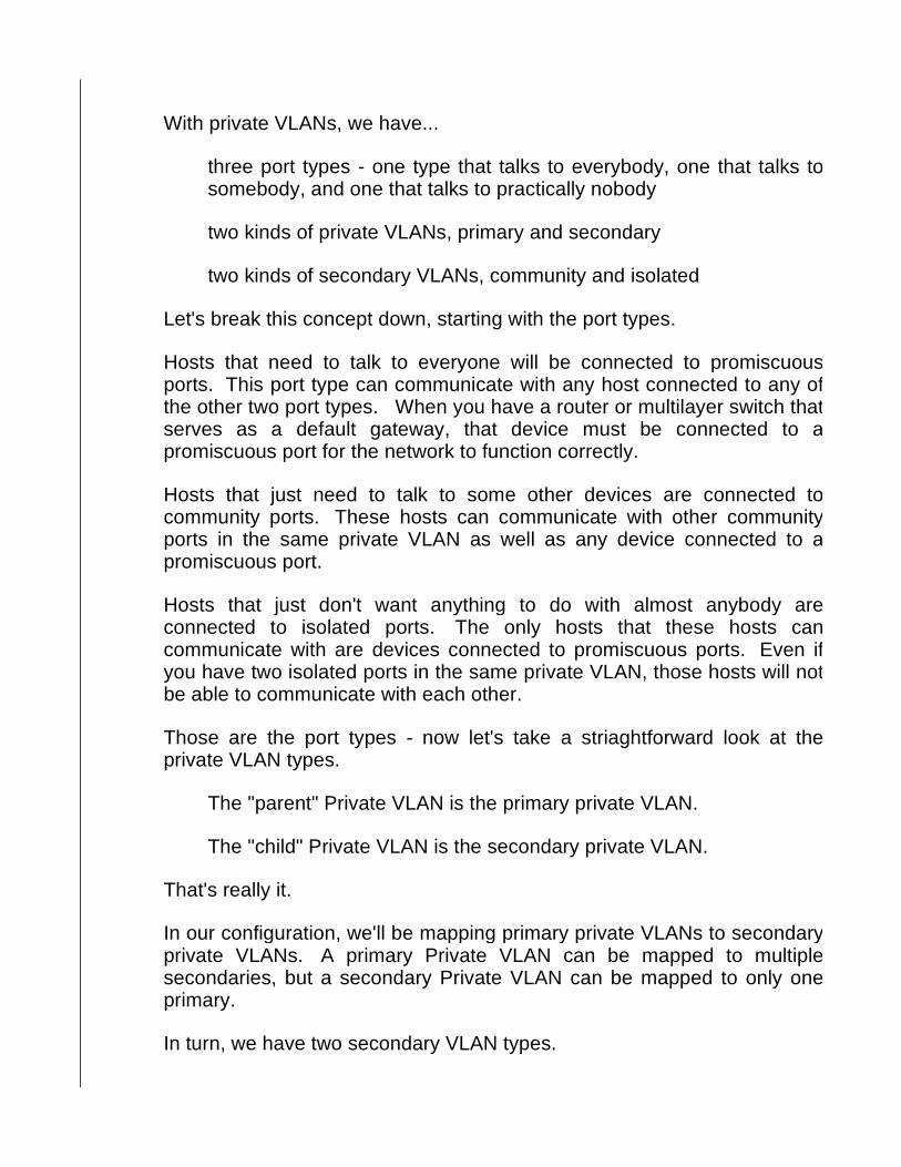
Each of these concepts is illustrated in the following diagram:
Host A has been placed into an isolated private VLAN, and will be able to communicate only with the router, which is connected to a promiscuous port. If we placed another host in the same isolated private VLAN that Host A is in now, the two hosts could not communicate with each other.
The other hosts are in a community private VLAN, so they can communicate with each other as well as the router. They can't communicate with Host A.
In the following configuration, we'll use the following VLANs and VLAN types:

VLAN 100 as a secondary private VLAN (community); ports in this VLAN are fast 0/1 - 5.
VLAN 200 as a secondary private VLAN (isolated); ports in this VLAN are fast 0/6- 10.
VLAN 300 will be the primary private VLAN. This port leads to a router via fast 0/12.
Creating the first VLAN with VLAN config mode is no problem, but look what happens when we try to make it a community private VLAN - or any kind of private VLAN, for that matter....
MLS(config)#vlan 100
MLS(config-vlan)#private-vlan ? association Configure association between private VLANs community Configure the VLAN as a communi ty private VLAN isolated Configure the VLAN as an is olated private VLAN primary Configure the VLAN as a pri mary private VLAN twoway-community Configure the VLAN as a two way community private VLAN
MLS(config-vlan)#private-vlan community Private VLANs can only be configured when VTP is in transparent mode
Please note that private VLANs can only be configured when VTP is in transparent mode. (Yeah, I know, like it says right there.) Once we do that, configuring VLAN 100 as a community private VLAN is no problem.
MLS(config-vlan)#exit MLS(config)#vtp mode transparent Setting device to VTP TRANSPARENT mode. MLS(config)#vlan 100 MLS(config-vlan)#private-vlan community
MLS(config)#vlan 200 MLS(config-vlan)#private-vlan isolated
Now we'll configure VLAN 300 as the primary private VLAN, and then associate those two secondary private VLANs with this primary private VLAN. (This association is not the mapping I mentioned earlier.)
MLS(config)#vlan 300 MLS(config-vlan)#private-vlan primary
MLS(config-vlan)#private-vlan association ? WORD VLAN IDs of the private VLANs to be confi gured add Add a VLAN to private VLAN list remove Remove a VLAN from private VLAN list

MLS(config-vlan)#private-vlan association 200,300
So at this point, we've...
Configured VTP to run in transparent mode
Created our secondary private VLANs, both isolated and community
Created our primary private VLAN
Created an association between the secondary and primary private VLANs
Just one more little thing to do... place the ports into the proper VLAN and get that mapping done! (Okay, that's two things.)
The switch port leading to the router is fast 0/12; that port must be made promiscuous.
SW1(config)#int fast 0/12 SW1(config-if)#switchport mode ? access Set trunking mode to ACCESS uncondi tionally dot1q-tunnel set trunking mode to TUNNEL uncondi tionally dynamic Set trunking mode to dynamically ne gotiate access or trunk mode private-vlan Set private-vlan mode trunk Set trunking mode to TRUNK uncondit ionally
SW1(config-if)#switchport mode private-vlan ? host Set the mode to private-vlan host promiscuous Set the mode to private-vlan promisc uous
SW1(config-if)#switchport mode private-vlan promisc uous
We'll also need the primary vlan mapping command on that interface:
SW1(config-if)#switchport private-vlan ? association Set the private VLAN associatio n host-association Set the private VLAN host assoc iation mapping Set the private VLAN promiscuou s mapping
SW1(config-if)#switchport private-vlan mapping ? <1006- 4094> Primary extended range VLAN ID of the privat e VLAN promiscuous port mapping <2- 1001> Primary normal range VLAN ID of the priva te VLAN promiscuous port mapping
SW1(config-if)#switchport private-vlan mapping 300 ?

WORD Secondary VLAN IDs of the private VLAN pr omiscuous port mapping add Add a VLAN to private VLAN list remove Remove a VLAN from private VLAN list
SW1(config-if)#switchport private-vlan mapping 300 100,200
Ports fast 0/1 - 5 are in VLAN 100. We'll use the interface rangecommand to configure that port range all at once with the private-vlan hostand private-vlan host-association commands.
SW1(config)#interface range fast 0/1 - 5
SW1(config-if-range)#switchport mode private-vlan ? host Set the mode to private-vlan host promiscuous Set the mode to private-vlan promisc uous
SW1(config-if-range)#switchport mode private-vlan host
SW1(config-if-range)#switchport private-vlan ? association Set the private VLAN associatio n host-association Set the private VLAN host assoc iation mapping Set the private VLAN promiscuou s mapping
SW1(config-if-range)#switchport private-vlan host-a ssociation ? <1006- 4094> Primary extended range VLAN ID of the privat e VLAN host port association <2-1001> Primary normal range VLAN ID of the private VLAN port association
SW1(config-if-range)#switchport private-vlan host-association 300 100
On ports fast 0/ 6 - 10 (in VLAN 200), it's about the same story, except the host-association command will end with 200 rather than 100.
SW1(config)#int range fast 0/6 - 10 SW1(config-if-range)#switchport mode private-vlan h ost SW1(config-if-range)#switchport private-vlan host-a ssociation 300 200
You can verify all of your private VLANs with show vlan private-vlan (really!) and on an interface level with the command show interface switchport (output truncated):
SW1#show int fast 0/6 switchport Name: Fa0/6 Switchport: Enabled Administrative Mode: private-vlan host Operational Mode: down
Administrative Trunking Encapsulation: negotiate Negotiation of Trunking: Off Access Mode VLAN: 1 (default) Trunking Native Mode VLAN: 1 (default) Administrative Native VLAN tagging: enabled Voice VLAN: none Administrative private-vlan host- association: 300 (Inactive) 200 (Inactive) Administrative private-vlan mapping: none Administrative private-vlan trunk native VLAN: none Administrative private-vlan trunk Native VLAN taggi ng: enabled Administrative private-vlan trunk encapsulation: do t1q
Note the trunk options at the end of that output. You can change those and other trunk-related values with the switchport private-vlan trunk commands.
SW1(config-if)#switchport private-vlan trunk native vlan 15 SW1(config-if)#switchport private-vlan trunk allowe d vlan 100,200,300
DHCP Snooping
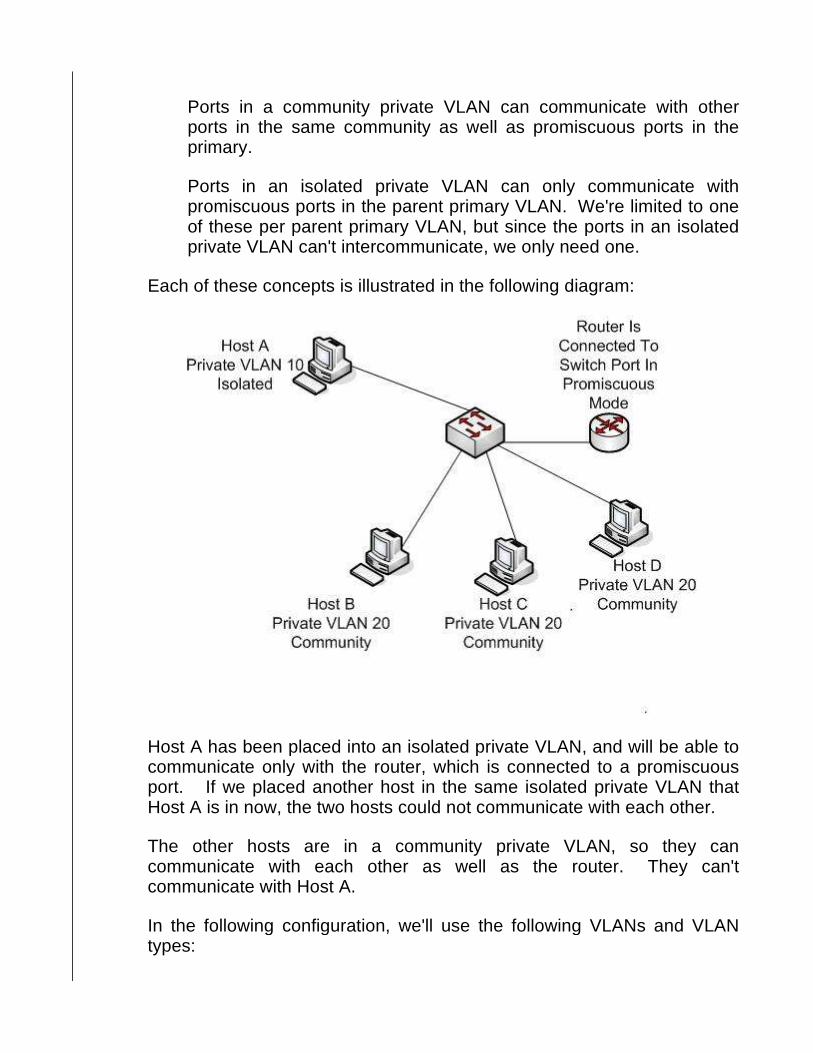
It may be hard to believe, but something as innocent as DHCP can be used for network attacks. The potential for trouble starts when a host sends out a DHCPDiscovery packet, it listens for DHCPOffer packets - and as we know, the host will accept the first Offer it gets!
Part of that DHCPOffer is the address to which the host should set its default gateway. In this network, there's no problem, because there's only one DHCP Server. The host will receive the DHCPOffer and set its default gateway accordingly. What if a DHCP server that does not belong on our network - a rogue DHCP server - is placed on that subnet?

Now we've got a real problem, because that host is going to use the information in the first DHCPOffer packet it receives - and if the host uses the Offer from the rogue DHCP server, the host will actually set its default gateway to the rogue server's IP address!
The rogue server could also have the host set its DNS server address to the rogue server's address as well. This opens the host and the network to several nasty kinds of attacks.
DHCP Snooping allows the switch to serve as a firewall between hosts and untrusted DHCP servers. DHCP Snooping classifies interfaces on the switch into one of two categories - trusted and untrusted.
DHCP messages received on trusted interfaces will be allowed to pass through the switch. Not only will DHCP messages received on untrusted interfaces be dropped by the switch, the interface itself will be placed into err-disabled state.

Now, you're probably asking "How does the switch determine which ports are trusted and which ports are untrusted?" By default, the switch considers all ports untrusted - which means we better remember to configure the switch to trust some ports when we enable DHCP Snooping!
First, we need to enable DHCP Snooping on the entire switch:
SW1(config)#ip dhcp snooping
You must then identify the VLANs that will be using DHCP Snooping. Let's use IOS Help to look at the other options available.
SW1(config)#ip dhcp snooping ? database DHCP snooping database agent information DHCP Snooping information verify DHCP snooping verify vlan DHCP Snooping vlan <cr>
SW1(config)#ip dhcp snooping vlan ? WORD DHCP Snooping vlan fist number or vlan range , example: 1,3-5,7,9-11

Note that you can use commas and dashes to define a range of VLANs for DHCP Snooping. We'll create three VLANs on this switch and then enable DHCP Snooping only for VLAN 4.
SW1(config)#int fast 0/2 SW1(config-if)#switchport mode access SW1(config-if)#switchport access vlan 2 % Access VLAN does not exist. Creating vlan 2
SW1(config-if)#int fast 0/3 SW1(config-if)#switchport mode access SW1(config-if)#switchport access vlan 3 % Access VLAN does not exist. Creating vlan 3
SW1(config-if)#int fast 0/4 SW1(config-if)#switchport mode access SW1(config-if)#switchport access vlan 4 % Access VLAN does not exist. Creating vlan 4
SW1(config)#ip dhcp snooping vlan 4
Assuming we have a trusted DHCP server off port 0/10, we would then trust that port with the following command:
SW1(config-if)#ip dhcp snooping trust
From your previous studies, you're familiar with the DHCP Relay Agent Information option. Usually referred to as Option 82 (we still don't know what happened to the first 81 options), this option can be disabled or enabled with the following command:
SW1(config)#ip dhcp snooping information option
DHCP Snooping is verified with the show ip dhcp snooping command.
SW1#show ip dhcp snooping Switch DHCP snooping is enabled DHCP snooping is configured on following VLANs: 4 Insertion of option 82 is enabled circuit-id format: vlan-mod-port remote-id format: MAC Option 82 on untrusted port is not allowed Verification of hwaddr field is enabled Interface Trusted Rate limit (pps) ------------------------ ------- ---------- ------ FastEthernet0/10 yes unlimited

The key information here, from top to bottom:
� DHCP Snooping is enabled on the switch � VLAN 4 is the only VLAN using DHCP Snooping � Option 82 is enabled, but not allowed on untrusted ports � The only trusted port is fast 0/10
Note the "rate limit" for the untrusted port is set to "unlimited". That rate limit refers to the number of DHCP packets the interface can accept in one second (packets per second).
Dynamic ARP Inspection
Just as we must protect against rogue DHCP servers, we have to be wary of rogue ARP users as well.
From your CCNA studies, you know all about Address Resolution Protocol and how it operates. A rogue device can overhear part of the ARP process in action and make itself look like a legitimate part of the network. This happens through ARP Cache Poisoning. (This is also known as ARP Spoofing - be aware of both names for your exam.)
ARP Cache Poisoning starts innocently enough - in this case, through the basic ARP process on a switch.
Host A is sending an ARP Request, requesting the host with the IP address 172.12.12.2 to respond with its MAC Address. Host B will receive the request, but before responding, Host B will make an entry in its local ARP cache mapping the IP address 172.12.12.1 to the MAC

address aa-aa-aa-aa-aa-aa. Once Host A receives that ARP Reply, both hosts will have a MAC address - IP address mapping for the remote host.
The problem comes in if a rogue host responds to the original ARP Request with its own MAC address.
Now Host A will make an entry in its ARP cache mapping the IP address 172.12.12.2 to cc-cc-cc-cc-cc-cc. Meanwhile, the rogue host will acquire Host B's true MAC address via ARP, which leads to this process:

1. When Host A transmits data to the IP address 172.12.12.2 with a MAC address of cc-cc-cc-cc-cc-cc, the data is actually being received by the rogue host.
2. The rogue host will read the data and then possibly forward it to Host B, so neither Host A nor Host B immediately notices anything wrong.
The rogue host has effectively placed itself into the middle of the communication, leading to the term man in the middle for this kind of network attack. When the rogue host does the same for an ARP Request being sent from Host B to Host A, all communications between Host A and Host B will actually be going through the rogue host.
Enabling Dynamic ARP Inspection (DAI) prevents this behavior by building a database of trusted MAC-IP address mappings. This database is the same database that is built by the DHCP Snooping process, and static ARP configurations can be used by DAI as well.
DAI uses the concept of trusted and untrusted ports, just as DHCP Snooping does. However, untrusted ports in DAI do not automatically drop ARP Requests and Replies.
Once the IP-MAC address database is built, every single ARP Request and ARP Reply received on an untrusted interface is examined. If the ARP message has an approved MAC-IP address mapping, the message is forwarded appropriately; if not, the ARP message is dropped.
If the interface has been configured as trusted, DAI allows the ARP message to pass through without checking the database of trusted mappings. DAI is performed as ARP messages are received, not transmitted.
Since DAI uses entries in the DHCP Snooping database to do its job, DHCP Snooping must be enabled before beginning to configure DAI. After that, the first step in configuring DAI is to name the VLAN(s) that will be using DAI.
SW1(config)#ip arp inspection ? filter Specify ARP acl to be applied log-buffer Log Buffer Configuration validate Validate addresses vlan Enable/Disable ARP Inspection on vlan s
SW1(config)#ip arp inspection vlan ? WORD vlan range, example: 1,3-5,7,9-11

SW1(config)#ip arp inspection vlan 4
Just as with DHCP Snooping, you can specify a range of VLANs with hyphens and commas. Also just as with DHCP Snooping, all ports are considered untrusted until we tell the switch to trust them, and we do that with the ip arp inspection trust interface-level command.
SW1(config)#int fast 0/4 SW1(config-if)#ip arp inspection trust
You may have noticed a validate option in the ip arp inspection command above. You can use the validate option to go beyond DAI's default inspection. Let's use IOS Help to take a look at our choices:
SW1(config)#ip arp inspection validate ? dst-mac Validate destination MAC address ip Validate IP addresses src-mac Validate source MAC address
You can actually specify validation of more than one of those addresses. Here's what happens with each:
"src-mac" compares the source MAC address in the Ethernet header and the MAC address of the source of the ARP message.
"dst-mac" compares the destination MAC address in the Ethernet header and the MAC destination address of the ARP message.
"ip" compares the IP address of the sender of the ARP Request against the destination address of the ARP Reply.
We'll use the "ip" option and then verify the configuration with show ip arp inspection.
SW1(config)#ip arp inspection validate ip
SW1#show ip arp inspection
Source Mac Validation : Disabled Destination Mac Validation : Disabled IP Address Validation : Enabled
Vlan Configuration Operation ACL Match Static ACL ---- ------------- --------- --------- ---------- 4 Enabled Active
Vlan ACL Logging DHCP Logging ---- ----------- ------------
4 Deny Deny
Vlan Forwarded Dropped DHCP Drops ACL Drops ---- --------- ------- ---------- --------- 4 0 0 0 0
Vlan DHCP Permits ACL Permits Source MAC Fa ilures ---- ------------ ----------- ------------- ------ 4 0 0 0
Vlan Dest MAC Failures IP Validation Failures Invalid Protocol Data ---- ----------------- ---------------------- ---------------------
Vlan Dest MAC Failures IP Validation Failures Invalid Protocol Data ---- ----------------- ---------------------- --------------------- 4 0 0 0
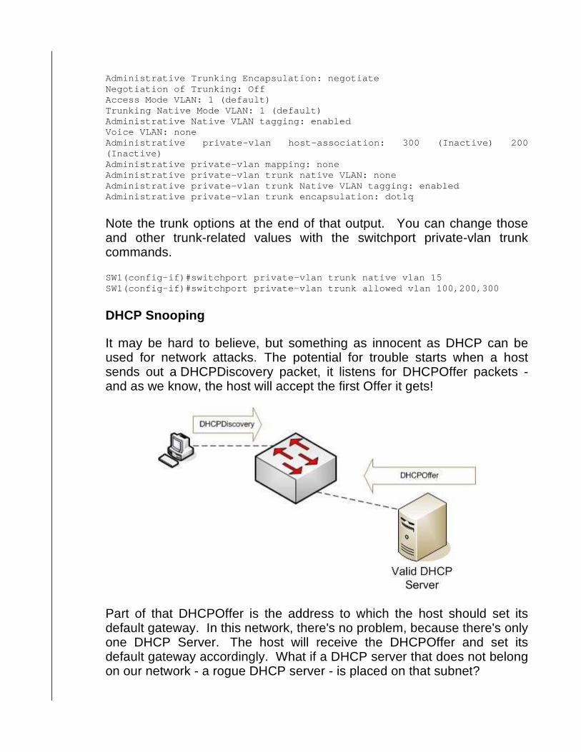
That show command results in a great deal of output, but as you apply DAI in your network, you should run this command regularly to spot potential rogue hosts on your network. A large number of validation failures is one indicator of such a rogue!
If you run DAI in your network, most likely you'll run it on all of your switches. Cisco's recommended trusted/untrusted port configuration is to have all ports connected to hosts run as untrusted and all ports connected to switches as trusted. Since DAI runs only on ingress ports, this configuration scheme ensures that every ARP packet is checked once, but no more than that.
There is no problem with running DAI on trunk ports or ports bundled into an Etherchannel.

IP Source Guard
We can use IP Source Guard to prevent a host on the network from using another host's IP address. IP Source Guard works in tandem with DHCP Snooping, and uses the DHCP Snooping database to carry out this operation.
As with DAI, DHCP Snooping must be enabled before enabling IP Source Guard. When the host first comes online and connects to an untrusted port on the switch, the only traffic that can reach that host are DHCP packets. When the client successfully acquires an IP address from the DHCP Server, the switch makes a note of this IP address assignment.
The switch will then dynamically create an VLAN ACL (VACL) that will only allow traffic with the corresponding source IP address to be processed by the switch. This IP address-to-port mapping process is called binding.
If the host pretends to be another host on that subnet, or to spoof that

host's IP address -- 172.12.12.100, for example -- the switch will simply filter that traffic because the source IP address will not match the database's entry for that port.
To enable IP Source Guard, use the ip verify source vlan command on the appropriate interfaces once DHCP snooping has been enabled with ip dhcp snooping. You can specify a VLAN range as we have in the past with commas and dashes, or with a range as shown below, entering the first and last numbers in the range.
SW1(config)#ip dhcp snooping ? database DHCP snooping database agent information DHCP Snooping information verify DHCP snooping verify vlan DHCP Snooping vlan <cr>
SW1(config)#ip dhcp snooping vlan ? WORD DHCP Snooping vlan fist number or vlan rang e, example: 1,3-5,7,9 -11
SW1(config)#ip dhcp snooping vlan 1 ? <1-4094> DHCP Snooping vlan last number <cr>
SW1(config)#ip dhcp snooping vlan 1 10
You do have the option of using both the IP and MAC source addresses to use as match criteria for incoming frames, or you can use the default of IP address only.
To use the MAC source addresses in addition to the IP address, use the port-security option with the ip verify source command. Using that command with no options will only use the IP address in the matching process.
SW1(config)#int fast 0/2 SW1(config-if)#ip verify source ?

port-security port security <cr>
MAC Address Flooding Attacks
Since ARP, IP addresses, and DHCP all have potential security issues, we can't leave MAC addresses out - because network attackers sure won't do so!
A MAC Address Flooding attack is an attempt by a network intruder to overwhelm the switch memory reserved for maintenance of the MAC address table. The intruder generates a large number of frames with different source MAC addresses - all of them invalid. As the switch's MAC address table capabilities are exhausted, valid entries cannot be made - and this results in those valid frames being broadcast instead of unicast.
This has three side effects, all unpleasant:
� As mentioned, the MAC address table fills to capacity, preventing legitimate entries from being made.
� The large number of unnecessary broadcasts quickly consumes bandwidth as well as overall switch resources
� The intruder can easily intercept packets with a packet sniffer, since the unnecessarily broadcasted packets will be sent out every port on the switch - including the port the intruder is using.
You can combat MAC Address Flooding with two of the features we addresses earlier in this section - port-based authentication and port security. By making sure our host devices are indeed who we think they are, we reduce the potential for an intruder to unleash a MAC Address Flooding attack on our network. The key isn't to fight the intruder once they're in our network - the key is to keep them out in the first place.
VLAN Hopping
We've seen how intruders can use seemingly innocent ARP and DHCP processes can be used to harm our network, so it shouldn't come as any surprise that Dot1q tagging can be used against us as well!
One form of VLAN Hopping is double tagging, so named because the

intruder will transmit frames that are "double tagged" with two separate VLAN IDs. As you'll see in our example, certain circumstances must exist for a double tagging attack to be successful:
� The intruder's host device must be attached to an access port.
� The VLAN used by that access port must be the native VLAN.
� The term "native VLAN" tips us off to the third requirement - dot1q must be the trunking protocol in use, since ISL doesn't use the native VLAN.
When the rogue host transmits a frame, that frame will have two tags. One will indicate native VLAN membership, and the second will be the number of the VLAN under attack. In this example, we'll assume that to be VLAN 100.
The trunk receiving this double-tagged frame will see the tag for VLAN 25, and since that's the native VLAN, that tag will be removed and then transmitted across the trunk - but the tag for VLAN 100 is still there!
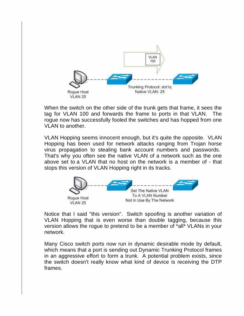
When the switch on the other side of the trunk gets that frame, it sees the tag for VLAN 100 and forwards the frame to ports in that VLAN. The rogue now has successfully fooled the switches and has hopped from one VLAN to another.
VLAN Hopping seems innocent enough, but it's quite the opposite. VLAN Hopping has been used for network attacks ranging from Trojan horse virus propagation to stealing bank account numbers and passwords. That's why you often see the native VLAN of a network such as the one above set to a VLAN that no host on the network is a member of - that stops this version of VLAN Hopping right in its tracks.
Notice that I said "this version". Switch spoofing is another variation of VLAN Hopping that is even worse than double tagging, because this version allows the rogue to pretend to be a member of *all* VLANs in your network.
Many Cisco switch ports now run in dynamic desirable mode by default, which means that a port is sending out Dynamic Trunking Protocol frames in an aggressive effort to form a trunk. A potential problem exists, since the switch doesn't really know what kind of device is receiving the DTP frames.
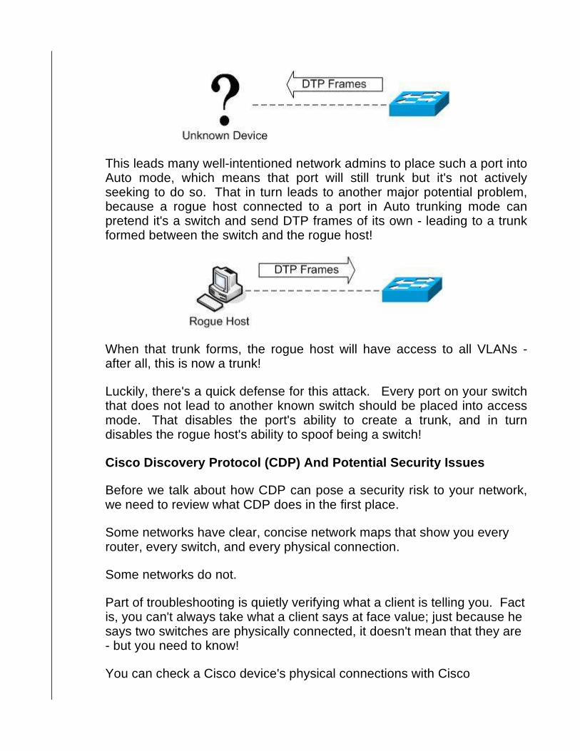
This leads many well-intentioned network admins to place such a port into Auto mode, which means that port will still trunk but it's not actively seeking to do so. That in turn leads to another major potential problem, because a rogue host connected to a port in Auto trunking mode can pretend it's a switch and send DTP frames of its own - leading to a trunk formed between the switch and the rogue host!
When that trunk forms, the rogue host will have access to all VLANs - after all, this is now a trunk!
Luckily, there's a quick defense for this attack. Every port on your switch that does not lead to another known switch should be placed into access mode. That disables the port's ability to create a trunk, and in turn disables the rogue host's ability to spoof being a switch!
Cisco Discovery Protocol (CDP) And Potential Securi ty Issues
Before we talk about how CDP can pose a security risk to your network, we need to review what CDP does in the first place.
Some networks have clear, concise network maps that show you every router, every switch, and every physical connection.
Some networks do not.
Part of troubleshooting is quietly verifying what a client is telling you. Fact is, you can't always take what a client says at face value; just because he says two switches are physically connected, it doesn't mean that they are - but you need to know!
You can check a Cisco device's physical connections with Cisco

Discovery Protocol, which runs by default on Cisco routers and switches, both globally and on a per-interface level.
For security purposes, many admins choose to disable CDP. Here's the command to see if CDP is indeed running on a router or switch:
Router1#show cdp Global CDP information: Sending CDP packets every 60 seconds Sending a holdtime value of 180 seconds Sending CDPv2 advertisements is enabled
That output means that CDP is indeed enabled. If you see the following, it's off.
Router1#show cdp % CDP is not enabled Router1#
Here's how to enable CDP:
Router1#conf t Enter configuration commands, one per line. End wi th CNTL/Z. Router1(config)#cdp run
The most commonly used CDP command is show cdp neighbor. I'll move over to a switch that has three physical connections to other hosts to show you the output of this command.
SW1#show cdp neighbor Capability Codes: R - Router, T - Trans Bridge, B - Source Route Bridge S - Switch, H - Host, I - IGMP, r - Repeater, P - Phone
Device ID Local Intrfce Holdtme Capability Platform Port ID SW2 Fas 0/12 170 S I WS-C2950-1 Fas 0/12 SW2 Fas 0/11 170 S I WS-C2950-1 Fas 0/11 R2 Fas 0/2 131 R 2520 Eth 0
This command shows us every device this switch is physically connected to, and gives us a wealth of information as well! From left to right...
Device ID is the remote device's hostname.
Local Interface is the local switch's interface connected to the remote host.
Holdtime is the number of seconds the local device will retain the contents of the last CDP Advertisement received from the remote host.

Capability shows you what type of device the remote host is. The first two connections are to a switch, and the third is to a router.
Platform is the remote device's hardware platform. The top two connections are to a 2950 switch, and the third is to a 2520 router.
Port ID is the remote device's interface on the direct connection.
This is an excellent command to verify what you're seeing on a network map or what a client is telling you. I've been in more than one situation where a client said one thing and CDP directly proved them wrong. It may be best to use it when they're not around, but it can also prove what you're telling the client.
Real-world courtesy: If your client has CDP turned off, and you turn it on for troubleshooting, turn it back off before you leave. It's good for the ol' job security, too.
The commands cdp run and no cdp run enable and disable CDP on a global basis. CDP runs globally on a Cisco device by default.
You may want to leave CDP on globally, but disable it on a particular interface. To enable or disable CDP on a per-interface basis, use cdp enable and no cdp enable.
SW1(config)#int fast 0/12 SW1(config-if)#no cdp enable SW1(config-if)#cdp enable
There are some other CDP commands you may find helpful, the first being show cdp neighbors detail. This command gives you a lot of detail about every CDP neighbor, so I won't put it all here, but here's a clip of the output dealing with just one of SW1's neighbors. Note that you can even see the neighbor's IOS version with this command!
SW1#show cdp neighbor detail ------------------------- Device ID: SW2 Entry address(es): Platform: cisco WS-C2950-12, Capabilities: Switch IGMP Interface: FastEthernet0/12, Port ID (outgoing por t): FastEthernet0/12 Holdtime : 148 sec
Version : Cisco Internetwork Operating System Software IOS (tm) C2950 Software (C2950-I6Q4L2-M), Version 12.1(19)EA1c, RELEASE SOFTWARE

(fc2) Copyright (c) 1986-2004 by cisco Systems, Inc. Compiled Mon 02-Feb-04 23:29 by yenanh
And right before I leave the client site, I'd run show cdp interface to verify that CDP is running on the interfaces that it should be running on - and not running on the others! Here's the partial output of this command on SW1:
SW1#show cdp interface FastEthernet0/1 is down, line protocol is down Encapsulation ARPA Sending CDP packets every 60 seconds Holdtime is 180 seconds FastEthernet0/2 is up, line protocol is up Encapsulation ARPA Sending CDP packets every 60 seconds Holdtime is 180 seconds FastEthernet0/3 is down, line protocol is down Encapsulation ARPA Sending CDP packets every 60 seconds Holdtime is 180 seconds
So if CDP's so great, why do many network admins choose to disable it on their networks? These vulnerabilities should sound familiar..
CDP sends all information in clear text
CDP offers no authentication
What we used to do is disable CDP globally, and that was that, but it's not so simple anymore. Just about every Cisco network management product uses CDP in some form to monitor the network and / or create reports. What you can do to minimize the risk of using CDP is to determine which interfaces really need to be running and which ones do not, and then run CDP on the interfaces that need it.
In case you run into networks that (gasp!) run non-Cisco devices, you may run into the Link Layer Discovery Protocol (LLDP). This is the industry-standard equivalent of CDP. Cisco devices can run it, but it's disabled by default.
Telnet And SSH
Telnet's a great way to communicate remotely with routers and switches, but there's a problem - all of the data sent to the remote host, including passwords, is transmitted in clear text. Any would-be network intruder

who intercepts the password transmission can then easily enter the network via Telnet, and then we're in real trouble!
Secure Shell (SSH) is basically "encrypted Telnet", since the basic operation of SSH is just like Telnet's, but the data (including the password) is encrypted.
For this very simple and very powerful reason, SSH is preferred over Telnet. But I can hear you now - "Then why does my company still use Telnet instead of SSH?" Telnet is very easy to set up, but SSH does take a little more work (and perhaps a little more hardware).
To use SSH, we'll have to use one of the following authentication methods:
� A local database on the router � Authentication via AAA, enabled with aaa new-model
Telnet allows the use of a password that's configured directly on the VTY lines, but SSH does not.
When using a local database for SSH, the first step is to configure login local on the VTY lines, rather than the login command we used for the Telnet configuration. Remove any passwords from the VTY lines as well. The login local command tells the switch to look to a database on the local device for valid username/password combinations.
R1(config)#line vty 0 4 R1(config-line)#login local R1(config-line)#transport input ssh
Then we'll create the username/password database.
SW2(config)#username mulligan password eaglepass SW2(config)#username mcdaniel password oklahoma SW2(config)#username hrace password missouri
When a user attempts to connect, the user must specify a username in this database and supply the password assigned to that username. Getting one or the other right isn't enough! That's much more secure than the one-password-fits-all configuration many Telnet configs use.
We could use the username/password command to create a database strictly for Telnet, and the login local command would have the same effect. Where the Telnet and SSH configuration differ is that the SSH config requires the following where Telnet does not:
� A domain name must be specified with the ip domain-name command
� A crypto key must be created with the crypto key generate rsa command
Create the domain name with the ip domain-name command. Also, if the router has no name, give it one with the hostname command.
R1(config)#ip domain-name bryantadvantage.com
When you generate the key with crypto key generate rsa, you'll get this readout:
R1(config)#crypto key generate rsa The name for the keys will be: HQ.HQ.com Choose the size of the key modulus in the range of 360 to 2048 for your General Purpose Keys. Choosing a key modulus grea ter than 512 may take a few minutes.
� How many bits in the modulus [512]: 1024 % Generating 1024 bit RSA keys, keys will be non-ex portable...[OK]
� If you're getting "unrecognized command" for valid SSH commands, the most likely reason is that you skipped this step.
You may want to accept only SSH on the vty lines and refuse attempted Telnet connections. To do so, enable only SSH with the transport input

command on the vty lines.
R1(config)#line vty 0 4 R1(config-line)#transport input SSH
To set the SSH timeout value, use the ip ssh time-out command. Note that IOS Help tells us to enter the command in seconds, not minutes.
R1(config)#ip ssh time-out ? <1-120> SSH time-out interval (secs)
To set the maximum number of SSH authentication retries, use the ip ssh authentication-retries command.
R1(config)#ip ssh authentication-retries ? <0-5> Number of authentication retries
Here are some other SSH options - another common one to set is the maxstartups option.
R1(config)#ip ssh ? authentication-retries Specify number of authenti cation retries break-string break-string logging Configure logging for SSH maxstartups Maximum concurrent session s allowed port Starting (or only) Port nu mber to listen on rsa Configure RSA keypair name for SSH source-interface Specify interface for sour ce address in SSH connections time-out Specify SSH time-out inter val version Specify protocol version t o be supported
� There's one more similarity between Telnet and SSH - you can still use ACLs to determine who should be able to connect via SSH, and you still use the access-class command to apply that ACL to the vty lines. Here, I've created a named ACL that denies a single host address and permits all others. The named ACL is then applied to the vty lines.
� R1(config)#ip access-list standard BLOCKNETWORK3 R1(config-std-nacl)#deny host 3.3.3.3 R1(config-std-nacl)#permit any R1(config-std-nacl)#line vty 0 4 R1(config-line)#access-class BLOCKNETWORK3 in
Review: Creating Banners
For legal reasons, you may want to warn users that unauthorized access
to the router or switch is prohibited. You can present this message, or any message you feel appropriate, with the banner command. (Inappropriate messages are best left for home lab practice!)
The banner command has a few options, the most common of which is the Message Of The Day (MOTD) option.
SW2(config)#banner ? LINE c banner-text c, where 'c' is a d elimiting character exec Set EXEC process creation banner incoming Set incoming terminal line banner login Set login banner motd Set Message of the Day banner prompt-timeout Set Message for login authenticat ion timeout slip-ppp Set Message for SLIP/PPP
We'll select motd, then use IOS Help to view our options.
SW2(config)#banner motd ? LINE c banner-text c, where 'c' is a delimiting character
That description of the LINE command can be a little confusing, so using a dollar sign as the delimiting character, here's how to configure a MOTD banner message.
SW1(config)#banner motd $ Enter TEXT message. End with the character '$'. Network down for router IOS upgrade at 10 PM EST to night! $
It doesn't matter what symbol or letter you use for the delimiting character, but you have to use the same one to begin and end the message. When I entered a dollar sign as the delimiting character, the switch told me to end my text message with the dollar sign.
I log out of the switch, then come back in, and I'm presented with the MOTD banner message.
SW1 con0 is now available
Press RETURN to get started.
Network down for router IOS upgrade at 10 PM EST to night!
SW1>
If we want to add a warning to that - say, a message warning against unauthorized access - we can create a login banner. That banner's

contents will appear after the MOTD, but before the login prompt.
SW2(config)#banner login % Enter TEXT message. End with the character %. Unauthorized Login Prohibited %
I've added a console line password of cisco as well:
line con 0 exec-timeout 0 0 password cisco logging synchronous login
When I log out and then log back in, I see the MOTD banner message followed by the login banner message.
SW1 con0 is now available
Press RETURN to get started.
Network down for router IOS upgrade at 10 PM EST to night! Unauthorized Access Prohibited By Law. But You Kne w That.
User Access Verification
Password: SW1>
This is how you'll see the banners appear in the config:
banner login ^C Unauthorized Access Prohibited By Law. But You Kne w That. ^C banner motd ^C Network down for router IOS upgrade at 10 PM EST to night! ^C
No matter what delimiting character you use, you'll see it represented as ^C in the config, so don't get thrown off by that.
Let's use IOS Help to look at our other options:
SW2(config)#banner ? LINE c banner-text c, where 'c' is a d elimiting character exec Set EXEC process creation banner incoming Set incoming terminal line banner login Set login banner motd Set Message of the Day banner prompt-timeout Set Message for login authenticat ion timeout slip-ppp Set Message for SLIP/PPP

You may want to present a banner message to users who have successfully authenticated, and you can do that with the banner exec command. You can use the ENTER key for hard breaks in a banner message, as shown below.
SW1(config)#banner exec * Enter TEXT message. End with the character '*'. Welcome to our nice, clean network. < enter key pr essed > Please keep it that way. *
After logging out and back in, the exec banner is presented after I successfully authenticate with the password cisco.
Network down for router IOS upgrade at 10 PM EST to night! Unauthorized Access Prohibited By Law. But You Kne w That.
User Access Verification
Password: Welcome to our nice, clean network. Please keep it that way. SW1>
A Little HTTP Security
� With products such as Security Device Manager, you'll need to set up a little something called "HTTP Secure Server". This is required since a web-based interface doesn't offer encryption, and that's a poor beginning for a security implementation.
� You'll need to enable HTTPS and HTTP local authentication with the ip http secure-server and ip http authentication local commands. That last command enables the use of a local database for HTTPS authentication; we create that with the username/ password command.
� Note the result of the ip http secure-server command.
� R1(config)#ip http server (enables HTTP) R1(config)#ip http authentication local R1(config)#ip http secure-server % Generating 1024 bit RSA keys, keys will be non-ex portable...[OK]
R1(config)# 11:44:05: %SSH-5-ENABLED: SSH 1.99 has been enabled R1(config)# 11:44:06: %PKI-4- NOAUTOSAVE: Configuration was modified. Issue "wri te
memory" to save new certificate
You could also use the crypto key generate rsa command to create that certificate.
Real-World Security Plans, Concerns, And Conversati ons
This section might help you on the CCNP SWITCH exam.
It will definitely help you in real-world networking situations - so while this topic isn't quite as exciting as configuring security solutions, it's just about as important.
This section is about the important of planning and having the right conversations before you start implementing your security solution.
Conversation with whom, you ask?
Define Expectations With Your Client
Your average client expects that when you're done implementing a network security solution, he'll be protected against everything and everyone that will ever want to do his network harm.
Forever.
You and I both know that this is an unrealistic expectation - but the client might not know that, and we need to do two things before we even get started on this job:
You need to define exactly what the limits are of the network solutions, what's guaranteed, what's not, and...
... you need to put this into writing.
Why go to this trouble? Let's say that you put in a security solution for a client, and everything's just fine for three years. Then someone somewhere comes up with a SuperVirus that infects his network.
That client will say many things, but "Oh well, that's just the way it goes" is not one of them. He may say a few things to their corporate attorney, and then you're really off to the races.

Here's how serious this is - Cisco has a security feature called AutoSecure that has a setting actually called One-Step Lockdown. Every Cisco security best practice you can think of is applied to this router. And before it even starts, you're presented with a warning that while Cisco has done everything they can to make this a secure solution, they can't guarantee that nothing bad will ever happen to that router.
And if Cisco can't guarantee it, you shouldn't be guaranteeing it either.
I don't say this to scare you - but it's just part of the world we live in. Be sure you clearly define expectations and limitations of any security solution with your client - and get him to sign off on it.
Don't Just Jump In
I've known a network admin or two in my life that weren't real big on planning - they just liked to put their hands on the routers and start configurin'.
I'm not always the most patient fellow in the world, but I never touch the client's network without taking care of some other tasks first. Your company's prerequisites likely differ, but these steps are a good idea no matter what you're implementing.
Test your solution on a pilot network. Nothing's worse than rolling out a security solution and then finding it's incompatible with your OSes, desktops, or anything else.
Run an audit or have an auditing firm do it. You've gotta know what's out there in the network before you can protect it - and you can't depend on the client or old inventory lists for a complete picture of the network. The audit should include both the hardware and software in use.
Take an incremental approach. If something's going to go wrong, I'd rather find out about it while it's affecting a small part of the network rather than the whole thing. Whether it's email or security, or anything in between, never migrate / install / implement on a network-wide basis if it can possibly be helped. Roll it out incrementally.
Have an emergency plan / rollback plan / parachute / whateveryouwannacallit. If something goes wrong, you cannot say

"Hey, I don't know what to do now." You need to be ready to put the network back into its prior, operational state. This goes for anything you install on a network.
And during the process, you should create a few things for your client (and you) as well:
Create a definitive security policy. Put it in writing - what will be allowed, what behaviors will be prohibited, and what actions will be taken when an undesirable behavior takes place?
Create an incident response plan. Look, after you leave, something's going to happen sooner or later. Have a plan in place to handle it and update it as time goes by.
Copyright © 2010 The Bryant Advantage. All Rights Reserved.