5 oxy-therm titan e-m - 10/09 - honeywell
TRANSCRIPT

OXY-THERM® TITAN™ oxy-fuel burner3 - 18.3 - 5E - m - 10/09
Specifications of OXY-THERM® TITAN™ burners
Materials of construction
Typical burner data
Fuel: natural gas at 15°C with 10.9 kWh/Nm3 HHV - sg = 0.6Oxygen: 90-100% purity
Stated pressures are indicative. Actual pressures are a function of air humidity, altitude, type of fuel and gas quality.
Gas OXY-THERM® TITAN™ burners 1-1/2” 2”
Capacity kW 586 to 3514
2928 to 9660
Thermal turndown from specified maximum capacity 8:1 8:1
Required pressures to burner inlet for maximum capacitiesNatural gas mbar <710 [1] <710 [1]
Oxygen mbar 138 283Typical oxygen to fuel volumetric ratios To natural gas 2.05:1 2.05:1[1] Nozzles drilled per order to accommodate various fuels, available supply pressures, and desired capacity.
Item number Burner part Material
1 Housing 304 SS (1.4301)2 Nozzle tip 310 SS (1.4841)3 Nozzle body 304 SS (1.4301)
4 Nozzle mixing plate 310 SS (1.4841)5 Block Alumina / Mullite refractory6 Mounting plate Carbon steel
1 32
5 6
4
w w w . m a x o n c o r p . c o mcombustion systems for industry
Maxon reserves the right to alter specifications and data without prior notice. © 2009 Copyright Maxon Corporation. All rights reserved.
OXY-THERM® TITAN™ oxy-fuel burner3 - 18.3 - 6E - m - 10/09
Selection criteria
Application details
OXY-THERM® TITAN™ burners can be used in furnaces, melters, unit melters, reverberatory furnaces, ladles and other high temperature applications.
OXY-THERM® TITAN™ burners have a unique design which minimizes flame length. For applications such as ladle heating or rotary melting, chamber length will often be compact, making it necessary to use a burner with a compact flame to avoid damaging the end or bottom of the chamber.
OXY-THERM® TITAN™ has a mounting flange and block design that will accommodate vertical fired applications requiring “down fired” mounting or for units that require mounting onto removable/hinged doors like rotary melters.
Application temperatures
The OXY-THERM® TITAN™ burners are suitable for furnaces and melters with temperatures up to 1650°C.
Cooling flow, either clean, dry air or oxygen, must be used whenever the burner assembly is in a high temperature atmosphere and is not firing. See installation and operating instructions for more details.
Fuels
OXY-THERM® TITAN™ burners are designed for firing on any fuel gas.
Flame supervision
Flame scanning is possible down the optional flame sensing connection. Flame scanner cannot be used through pilot location to see main flame. Flame rod is not available.
Piloting and ignition
Oxy-fuel pilots and air-fuel pilots are available. Refer to pages 3-18.3-10 and 11 for pilot dimensions and specifications.
Oxygen/gas ratio controls
Correct fuel/oxygen ratio control valves should be selected. Trims should be selected for compatibility with oxygen. MAXON’s
MICRO-RATIO® valves are available with oxygen trim. For more accurate ratio control, use MAXON SMARTLINK® MRV valves,
or for best performance, use SMARTFIRE® Intelligent Combustion Control System. Calibrated flow meters in the fuel and the oxygen lines are recommended for establishing accurate volumetric flow rates.
Burner blocks
OXY-THERM® TITAN™ burners are available with refractory block only.
In addition to maximum furnace temperatures, temperature variations and furnace atmosphere (chemical composition) can also be factors used to determine the appropriate block material. Alternate materials are available upon request. Please contact MAXON for further details.
Block materialType Alumina / Mullite
Maximum temperature 1650° C
w w w . m a x o n c o r p . c o mcombustion systems for industry
Maxon reserves the right to alter specifications and data without prior notice. © 2009 Copyright Maxon Corporation. All rights reserved.

OXY-THERM® TITAN™ oxy-fuel burner3 - 18.3 - 7E - m - 10/09
Combustion oxygen pressure vs. flow
OXY-THERM® TITAN™ burners may be adjusted to operate on ratio, with excess oxygen (oxidizing environment) or with excess fuel (reducing environment). Typical applications will operate with 1-2% excess oxygen.
If burners are shut down while the furnace remains hot, it is recommended to continue a small flow of oxygen for cooling of the burner. Alternatively, air or nitrogen can be used for burner cooling during burner shut down. Total elimination of oxygen flow in hot furnaces can thermally damage burner fuel inserts and other parts. For extended shut downs in hot furnaces, it is recommended that the fuel insert be removed.
Combustion oxygen pressure - 1-1/2” OXY-THERM® TITAN™ burners
Combustion oxygen pressure - 2” OXY-THERM® TITAN™ burners
10
100
1000
1 10 100 1000
Combustion Oxygen Pressure (mbar)
Co
mb
ust
ion
Oxy
gen
Flo
w (m
3 /hr)
10
100
1000
10000
1 10 100 1000
Combustion Oxygen Pressure (mbar)
Com
bust
ion
Oxy
gen
Flow
(m
3 /hr)
w w w . m a x o n c o r p . c o mcombustion systems for industry
Maxon reserves the right to alter specifications and data without prior notice. © 2009 Copyright Maxon Corporation. All rights reserved.

OXY-THERM® TITAN™ oxy-fuel burner3 - 18.3 - 8E - m - 10/09
Flame lengths - 1-1/2” OXY-THERM® TITAN™ burners
Flame lengths - 2” OXY-THERM® TITAN™ burners
Contact MAXON for flame length details when selecting a burner with maximum capacity below 3500 kW
Contact MAXON for flame length details when selecting a burner with maximum capacity below 8800 kW
0
0.5
1
1.5
2
2.5
3
0 500 1,000 1,500 2,000 2,500 3,000 3,500 4,000
Capacity (kW)
Flam
e L
eng
th (
m)
0
0.5
1
1.5
2
2.5
3
0 1,000 2,000 3,000 4,000 5,000 6,000 7,000 8,000 9,000 10,000
Capacity (kW)
Fla
me
Len
gth
(m
)
w w w . m a x o n c o r p . c o mcombustion systems for industry
Maxon reserves the right to alter specifications and data without prior notice. © 2009 Copyright Maxon Corporation. All rights reserved.

OXY-THERM® TITAN™ oxy-fuel burner3 - 18.3 - 9E - m - 10/09
Dimensions and weights
1) 1/4” NPT combustion oxygen pressure tap
2) 3/8” NPT gas inlet
3) Fuel gas inlet
4) 3/8” NPT air inlet
5) Optional sealed boosted air pilot assembly shown. See partial view B-B for optional oxy-pilot assembly
6) Distance to remove gas insert assembly
7) Nameplate
8) 3” NPT combustion oxygen inlet
9) 1/4” NPT fuel gas pressure tap
10) 3/4” NPT coupling location for optional flame sensing device
11) 1/2” NPT oxygen inlet
12) 3/8” NPT gas inlet
13) Optional oxy-pilot assembly
View A-A
View B-B
Dimensions in mm unless stated otherwiseSize A B C D Ø E F G J
1-1/2” 678 230 448 394 6 775 457 2292” 749 230 519 394 6 914 457 229
Size K L M N P Q NPT Weight kg1-1/2” 210 70 229 457 16 1-1/2” 84
2” 210 70 229 457 16 2” 88
Q3
5
1
2
4
A
D Ø
B C
EF6
A-A
108
9
G
N
M
L
L
K
K
LL
K KJ
P Ø
7
131211
w w w . m a x o n c o r p . c o mcombustion systems for industry
Maxon reserves the right to alter specifications and data without prior notice. © 2009 Copyright Maxon Corporation. All rights reserved.

OXY-THERM® TITAN™ oxy-fuel burner3 - 18.3 - 10E - m - 10/09
Accessories
Oxy-pilot
1) 1/2” NPT
2) 3/8” NPT fuel inlet
3) Spark ignitor
4) 1/2” NPT oxygen inlet
View A-A
Dimensions in mm unless stated otherwiseA B C D
191 33 56 41
Oxy-fuel pilot specifications
Gas flow Flow m3/h Pressure mbar Capacity kW
Natural gas 1.0 12 10Propane 0.4 5 10
Oxygen 5.7 20 10
A
B1
2
View A-A
C
3
4
D
w w w . m a x o n c o r p . c o mcombustion systems for industry
Maxon reserves the right to alter specifications and data without prior notice. © 2009 Copyright Maxon Corporation. All rights reserved.

OXY-THERM® TITAN™ oxy-fuel burner3 - 18.3 - 11E - m - 10/09
Air-fuel boosted pilot
1) Pressure tap 1/8” NPT
2) Gas inlet 1/4” NPT
3) Air inlet 3/8” NPT
Dimensions in mm unless specified otherwiseA B C D E F G H J K
304 128 129 88 104 71 132 123 112 30°
Air-fuel boosted pilot specifications
Gas flow Flow m3/h Pressure mbar Capacity kW
Natural gas 2.6 25 27Air 8.5 27 27
D E
B CA
H
F
G
J
K
1
2
3
w w w . m a x o n c o r p . c o mcombustion systems for industry
Maxon reserves the right to alter specifications and data without prior notice. © 2009 Copyright Maxon Corporation. All rights reserved.
OXY-THERM® TITAN™ oxy-fuel burner3 - 18.3 - 12E - m - 10/09
Model number description
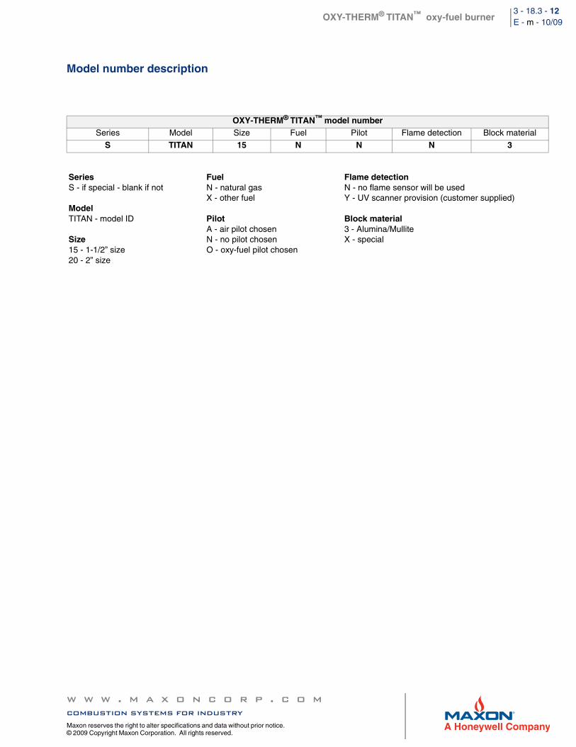
OXY-THERM® TITAN™ model numberSeries Model Size Fuel Pilot Flame detection Block material
S TITAN 15 N N N 3
SeriesS - if special - blank if not
ModelTITAN - model ID
Size15 - 1-1/2” size20 - 2” size
FuelN - natural gasX - other fuel
PilotA - air pilot chosenN - no pilot chosenO - oxy-fuel pilot chosen
Flame detectionN - no flame sensor will be usedY - UV scanner provision (customer supplied)
Block material3 - Alumina/MulliteX - special
w w w . m a x o n c o r p . c o mcombustion systems for industry
Maxon reserves the right to alter specifications and data without prior notice. © 2009 Copyright Maxon Corporation. All rights reserved.

OXY-THERM® TITAN™ oxy-fuel burner3 - 18.3 - 13E - m - 10/09
Installation and operating instructions for OXY-THERM® TITAN™ burners
Application requirements
View port
A view port to observe burner flame is essential to inspect flame aspect. Locate the view port downstream of the flame, looking back to the burner block. Make sure the complete flame can be evaluated.
Support burner oxygen and gas piping
The OXY-THERM® TITAN™ burner shall not be used as support for the piping to the burner. Gas and oxygen piping shall be supported in such a way that no additional loads will be created on the burner. Flexible connections are typically recommended for
all OXY-THERM® TITAN™ installations for both fuel and oxygen to prevent transferring mechanical loads or vibrations to the burner’s ceramic parts.
Burner mounting flange loads
Check burner weight and reinforce burner mounting flange or combustion chamber/furnace back wall if necessary to accept complete burner weight.
Installation instructions
Storage of OXY-THERM® TITAN™ burners
OXY-THERM® TITAN™ burners shall be stored dry (inside). Burner blocks have been cured carefully before shipment and shall be kept dry. Wetting of the blocks could result in premature failures.
Handling of OXY-THERM® TITAN™ burners
OXY-THERM® TITAN™ burners are shipped as complete units. Handle burners with care, using proper equipment, during unpacking, transport, lifting and installation. Any impact on the burner could result in damage.
Flange the burner to the installation
Bolt the burner to the installation’s burner mounting flange. Use proper gasketing. Tighten the flange bolting with correct torque. Retighten all bolts after first firing and regularly after commissioning.
w w w . m a x o n c o r p . c o mcombustion systems for industry
Maxon reserves the right to alter specifications and data without prior notice. © 2009 Copyright Maxon Corporation. All rights reserved.

OXY-THERM® TITAN™ oxy-fuel burner3 - 18.3 - 14E - m - 10/09
Burner mounting
Furnace/combustion chamber requirements
Sketch 1: sheet metal combustion chambers, furnaces without internal insulation or with soft wall internal insulation: flange / opening internal diameter shall be = Ø A
Sketch 2: furnaces or ovens with brick walls: opening in brick wall shall be = Ø B (to be stuffed with castable refractory)
Sketch 1 Sketch 2
Dimensions in mm unless stated otherwiseBurner size A Ø B Ø
1-1/2” 420 5402” 420 540
Ø A Ø A Ø AØ B
w w w . m a x o n c o r p . c o mcombustion systems for industry
Maxon reserves the right to alter specifications and data without prior notice. © 2009 Copyright Maxon Corporation. All rights reserved.
OXY-THERM® TITAN™ oxy-fuel burner3 - 18.3 - 15E - m - 10/09
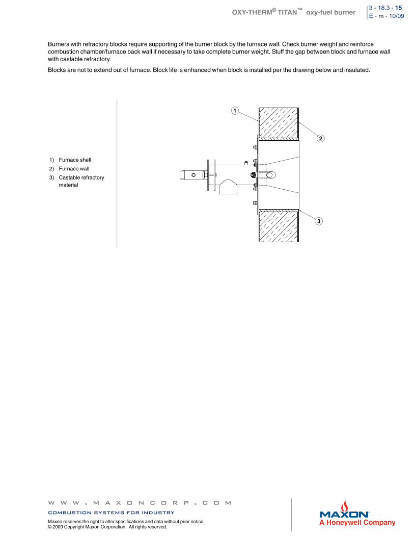
Burners with refractory blocks require supporting of the burner block by the furnace wall. Check burner weight and reinforce combustion chamber/furnace back wall if necessary to take complete burner weight. Stuff the gap between block and furnace wall with castable refractory.
Blocks are not to extend out of furnace. Block life is enhanced when block is installed per the drawing below and insulated.
1) Furnace shell
2) Furnace wall
3) Castable refractory material
1
2
3
w w w . m a x o n c o r p . c o mcombustion systems for industry
Maxon reserves the right to alter specifications and data without prior notice. © 2009 Copyright Maxon Corporation. All rights reserved.

OXY-THERM® TITAN™ oxy-fuel burner3 - 18.3 - 16E - m - 10/09
Start-up instructions
Instructions provided by the company or individual responsible for the manufacture and/or overall installa-tion of a complete system incorporating MAXON burners take precedence over the installation and operat-ing instructions provided by MAXON. If any of the instructions provided by MAXON are in conflict with local codes or regulations, please contact MAXON before initial start-up of equipment.
First firing or restart after shut-down
During first start-up of the burner, and after every longer installation shut-down, the temperature rise shall be limited. Allow the burner to fire on low fire for some time to allow the parts to heat up slowly.
Checks during and after start-up
During and after start-up, check the integrity of the system. Check all bolted connections after first firing (first time on temperature) and retighten if necessary.
Pilot ignition
Before ignition of the pilot, adjust the oxygen to the minimum burner oxygen flow. Set pilot gas flow to the correct value before pilot ignition attempt.
Main burner ignition
Set correct gas flow for burner minimum capacity before attempt of main burner ignition.
After ignition of main burner, allow some time on minimum capacity to allow the burner parts to heat up slowly.
Burner adjustment and control
Oxygen-fuel burners require accurate control of both fuel and oxygen for optimum performance. Piping to individual burners should include control valves for both oxygen and fuel. In addition, flow meters for oxygen and fuel capable of local or remote readout are required for proper burner adjustment.
If required, flame sensing may be accomplished by UV scanner. Burner design can incorporate a UV scanner port suitable for supervision of both pilot and main flames. UV scanner, if used, should be kept as close to burner as feasible. Heat block, if used, may affect signal strength with some brands of UV scanners.
Read the combustion system manual carefully before initiating the start-up and adjustment procedure. Verify that all of the equipment associated with and necessary to the safe operation of the burner system has been installed correctly, that all pre-commissioning checks have been carried out successfully and that all safety-related aspects of the installation are properly addressed.
CAUTION: Oxygen should only be used with approved materials, properly cleaned pipe and equipment, and specially designed systems. Ordinary materials can be extremely flammable in the presence of oxygen and air enriched with oxygen.
w w w . m a x o n c o r p . c o mcombustion systems for industry
Maxon reserves the right to alter specifications and data without prior notice. © 2009 Copyright Maxon Corporation. All rights reserved.

OXY-THERM® TITAN™ oxy-fuel burner3 - 18.3 - 17E - m - 10/09
Maintenance and inspection instructions
Safety requirements
Regular inspection, testing and recalibration of combustion equipment according to the installation manual is an integral part of its safety. Inspection activities and frequencies shall be carried out as specified in the installation manual.
Perform the following activities at least annually as part of a recommended preventative maintenance routine:
Inspect burner internal parts for wear and oxidation.Inspect associated control instruments and devices for function with particular attention to all safety permissive switches.Perform leak tests on fuel shut-off valve according to any schedule established by the authority having jurisdiction.
Visual inspections
Regular visual inspection of all connections (oxygen and gas piping to the burner, bolting of the burner to the furnace) and burner flame size and aspect are essential for safe operation.
Spare parts
Keep local stock of spark ignitor if burner is equipped with pilot. It is not recommended to keep local stock of other burner parts. Consult installation manual for burner spare parts and system accessories.
w w w . m a x o n c o r p . c o mcombustion systems for industry
Maxon reserves the right to alter specifications and data without prior notice. © 2009 Copyright Maxon Corporation. All rights reserved.