4l80e d1 transbrake instructions - jake’s performance€¦ · 4l80e d1 transbrake instructions...
TRANSCRIPT
4L80E D1 Transbrake Instructions Installation of the Jake's Performance 4L80E Transbrake will require some internal modifications. These are relatively simple but are best done during a rebuild or by a professional transmission technician. However we will provide instruction here for the Do-it-Yourself installer. Parts included:
Valve body assembly with separator plate and accumulator blockoff plate.
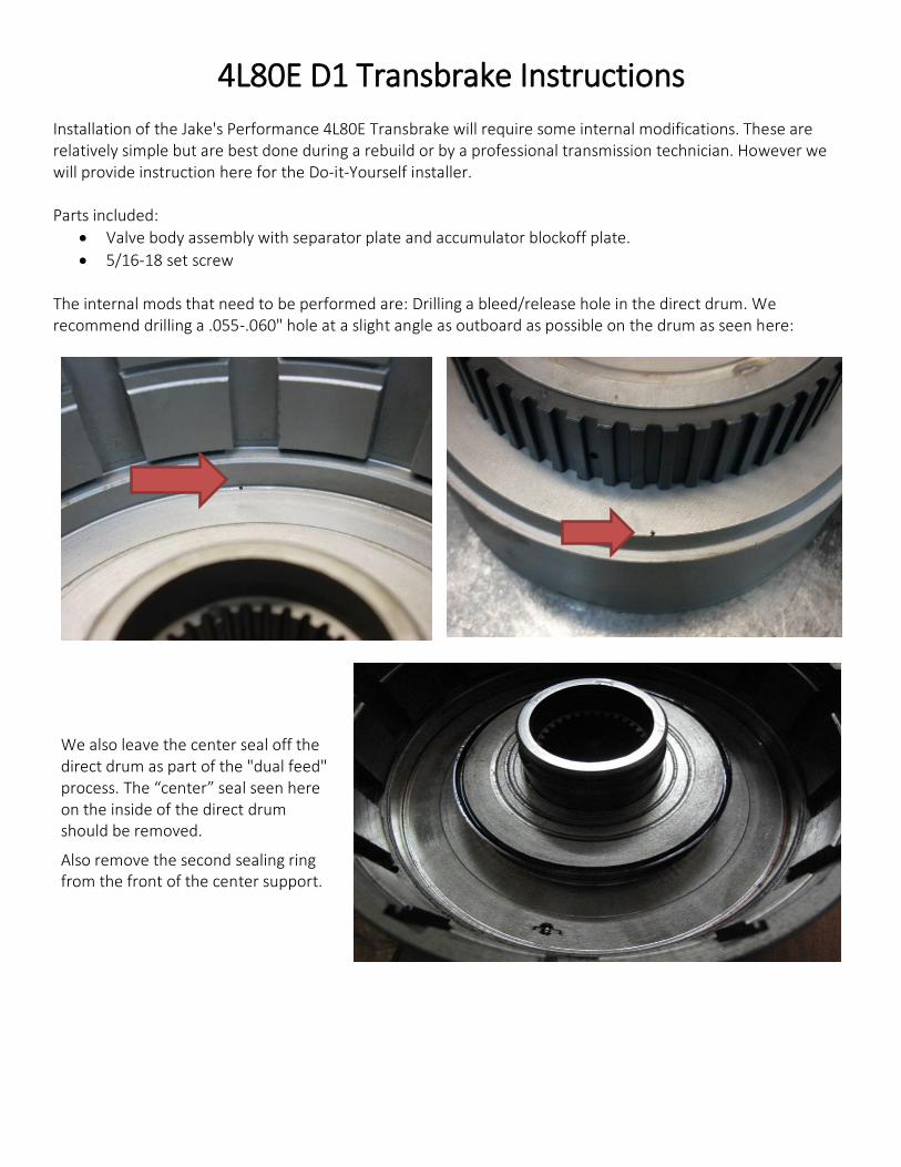
5/16-18 set screw The internal mods that need to be performed are: Drilling a bleed/release hole in the direct drum. We recommend drilling a .055-.060" hole at a slight angle as outboard as possible on the drum as seen here:
We also leave the center seal off the direct drum as part of the "dual feed" process. The “center” seal seen here on the inside of the direct drum should be removed.
Also remove the second sealing ring from the front of the center support.
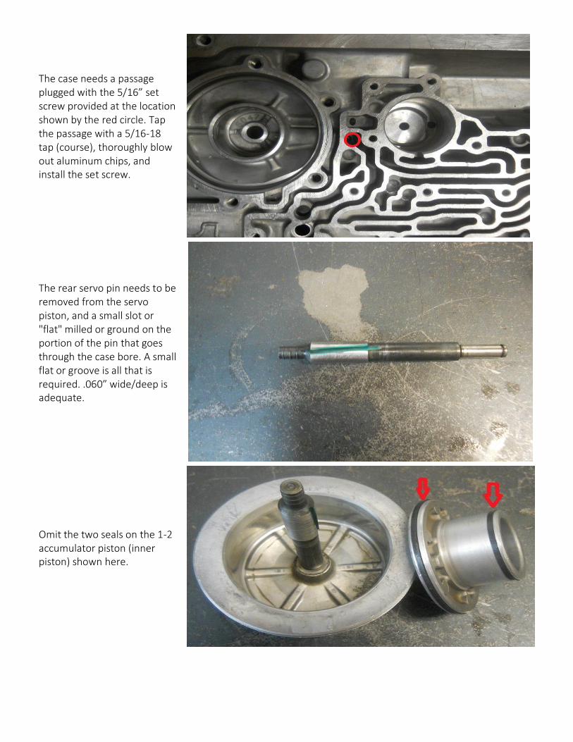
The case needs a passage plugged with the 5/16” set screw provided at the location shown by the red circle. Tap the passage with a 5/16-18 tap (course), thoroughly blow out aluminum chips, and install the set screw.
The rear servo pin needs to be removed from the servo piston, and a small slot or "flat" milled or ground on the portion of the pin that goes through the case bore. A small flat or groove is all that is required. .060” wide/deep is adequate.
Omit the two seals on the 1-2 accumulator piston (inner piston) shown here.
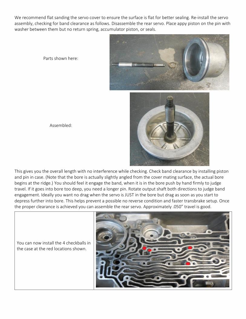
We recommend flat sanding the servo cover to ensure the surface is flat for better sealing. Re-install the servo assembly, checking for band clearance as follows. Disassemble the rear servo. Place appy piston on the pin with washer between them but no return spring, accumulator piston, or seals.
Parts shown here:
Assembled:
This gives you the overall length with no interference while checking. Check band clearance by installing piston and pin in case. (Note that the bore is actually slightly angled from the cover mating surface, the actual bore begins at the ridge.) You should feel it engage the band, when it is in the bore push by hand firmly to judge travel. If it goes into bore too deep, you need a longer pin. Rotate output shaft both directions to judge band engagement. Ideally you want no drag when the servo is JUST in the bore but drag as soon as you start to depress further into bore. This helps prevent a possible no reverse condition and faster transbrake setup. Once the proper clearance is achieved you can assemble the rear servo. Approximately .050” travel is good.
You can now install the 4 checkballs in the case at the red locations shown.
You can install the Jake's Performance Transbrake valve body at this time. Install the solenoids, internal harness, filter, and pan. Leave the EPC (force motor or pressure control solenoid) out of the valve body and tie it up on the passenger side away from the park linkage.
Wiring the transbrake consists of tying into the B wire, typically yellow wire, that controls the B (2-3) shift solenoid on the control harness going to the transmission. Go through a momentary switch to a good chassis ground. Activating the switch in the manual low position will engage the transbrake. Note: PCM tuning may be required. You must program the controller to not allow a 1-2 upshift while the transmission is in manual low.
The transbrake will engage if the PCM commands any upshift causing parts damage or injury. We also do not recommend downshifting into manual low while moving with the Pro brake. Our D1 4L80E transbrake design allows for very fast transbrake setup and release times as well as minimizes circuit volume in several circuits in the transmission. This makes it very quick acting and capable of holding more HP on the transbrake and clutches. As a byproduct of the design, it applies the low gear band quicker than the intermediate (2nd) gear clutches can release, creating a slight bind on a 2-1 downshift. Therefore, we recommend no manual downshift to low gear while moving. It is OK for the ECM or controller to make a downshift, and it’s OK to manually downshift all other gears.
Disclaimer: Due to the nature of high performance and racing applications, the products offered by Jake’s Performance are sold without any express warranty or any implied warranty of merchantability or fitness for the intended purpose. No consequential damages of any type which may happen from the purchase, installation or use of any of this merchandise or products will be the responsibility of Jake’s Performance. Buyers understand and accept the possibility of serious injury and/or death and damage from use of any products whether used on the street or racetrack.
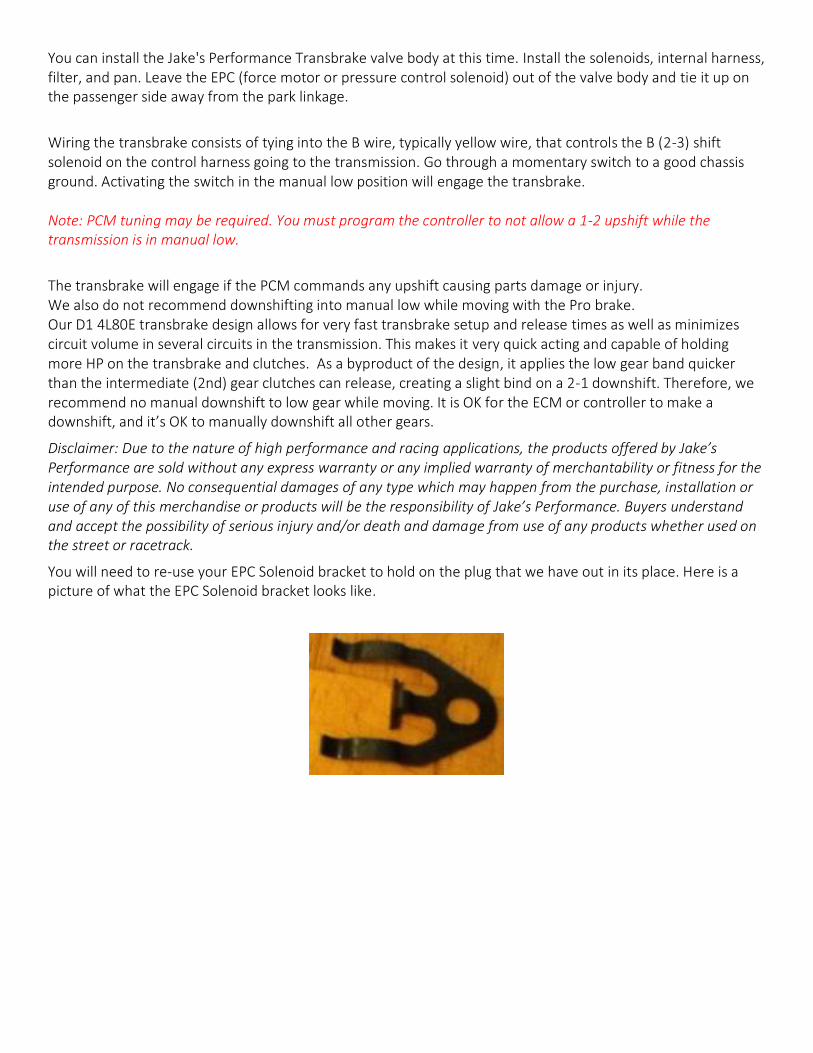
You will need to re-use your EPC Solenoid bracket to hold on the plug that we have out in its place. Here is a picture of what the EPC Solenoid bracket looks like.