4iixamherst systems-- amherst systems inc. advanced tactical electronic warfare environment...
TRANSCRIPT

A Z,
~-~-~. 4IIXAMHERST SYSTEMS INC.
132 CAYUGA ROAD *BUFFALO, NEW YORK 14225
ADVANCED
. ~TACTIC.AL ELECTRONIC WsARFARE ~ ~ENV IRONNENT S I~<ULATOR
(ATEWE-,S)
~A-'REAULTE SOFTWýARPE4LI ~ DESIGN DESCRIPTION
HAY 1983
Contract Number NOOO'4 82-C 2136
-. 41.!
,'A,.
~~--4
&W~!.
r ' k
...........*--..2IIBe1 A r¼:-, abl...At. .~..*h
*~- f) 7.**-

-- AMHERST SYSTEMS INC.
ADVANCED
TACTICAL ELECTRONIC WARFARE
ENVIRONMENT SIMULATOR
(ATEWES)
REALTIME SOFTWARE
DESIGN DESCRIPTION
MAY 1983
Prepared by
AMHERST SYStEMS, INC.BUFFALO, NEW YORK 14225
DTIS TAB&DTIC AP IPrepared for
Unan ou-, '-
"NAVAL RESEARCH LABORATORY EL C FWASHINGTON, D.C. 20375 "a"
Di~tr ,z - :/ -, ,••
Availabij i,va -b .t'. ."- CONTRACT NUMBER N00014-82-C-2136
This document has been app-cved
fox public releaLSe and sale; itsdistribution is unlimitod-
132CAYUGA ROAD * BUFFALO, NEW YORK 14225 * 716-631-0610

TABLE OF CONTENTS
SECTION PAGE
2 SYSTEM ARCITECTURE . . ..................... 3
3 PROGRAM INIRN & . . 5. . ........ *
3.1 SUBIROUTINE AZRTR . ................. . .. . .6
3.2 SUIROUTINE CLDX ...... . . . . . . .e.......... 6
3.3 S UBIROUTIN CRD a . 7
3.4 SUBROUTINE GDrLT ............... , . . ..... 73.5 SUBROUTINE G . . . . 9 . . ............. 73.6 SUBIROUTINE MIDS .... • . ..... . .• . . . . . . . 73.7 SUBROUTINE IDDAT e . • , • . . .o a e a o • * ........ 7
3.8 SUBROUTINEZI . . . . ... . . . .. .. . . 83.9 SUBIROUTIN E ...... * • . • • ........... 83.10 SUBROUTINE START * . . . . . . .. .. . . . . . . . . .*
3.11 SUBROUTINE TIRIC . * & * o * * 0 . . 8
4 PROGIAM OTASK . ........... .. . . . . o . . * . 9
4.1 SUBIOUTINE CNU . . . . . . . . 9 # 9 .. .. • .# • 10
4.2 SUBROUTIPS DSPLY . . . . . . . o . . 10
4.3 SUIROUTINE DSPT' * & * ..• .............. 9 ... 11
"4.'4 SUBROUTINE DSTAT v a 0 . a . * 0 . . a . 11
-4.5 SUBIROUTINE El= . . . . . .. . . .. 0 . . .. . . 114. .6 SUBRtOUTINE LISA!' . .......... ... .. ... 0 a
4.7 SUIROUTINE LISEI . . . . . . . . . . . . . . . . . . 12
4.8 SUBROUTINE LISP . . . . . . . . . . . ................. ... 12

4.9 SUBROUTINE LISPI . . . . . . . . . ... . 12
4.10 SUBROUTINE OCM0ND ....... . . . • ............ 12
4.11 SUBROUTINE SPECO . . . . . . . . . . . . . . . . . . . . . . . 13
5 PROGRAM REA.TM .0. . . . . . . . . . . . ..0. . . . . . . . . . 14
5.1 CONTROL FILE . • # • . • . . • . .* . . . . . . . . . . . . . 14
5.2 HONIT" (CONTROL LOOP) . . . . . . . . . . . . . . . . . . . . . 18
5.3 CLKAST (TIMING CONTROL). ......... . ........ . 19
5.3 SUBROUTINE ADVSCN . . . . . . . . . . . . . . . . . . . . . . 20
5.5 SUBROUTINE ATAN ................... , .... 21
3.6 SUBROUTINE BACL• .......... , ............ 215.7 SUBROUTINE BACKUP . . . . . . . . . . . . . . . . . . . . . . . 21
5.8 SUBROUTINE CEFIL • . . . . . . . . . . . . . . . .. 21
5.9 SUBROUTINE CKDED * . . . .. . v .. . ... . 21
5.10 SUBROUTINE CLOSDI . . . . . . . . . . . . . . . . . . . . . . . 22
5.11 " SUBROUTINE CLOSET. • • • • . • • . . . .. ....... , .... 22
5.12 SUBROUTINE COS ......... . . .. ...... 22
5.13 SUBROUTINE CPFTL o • • • . ........ . ......... 22
5.14 SUIBOOTINE DAEL ........................ 22
5.15 SUBROUTINE DAPL o .... • • • • • • • • , • • • • ..... 23
5.16 SUBROUTINE DEE . • ...... . ........ .. . 23
5.17 SUBROUTINE DELEK ..... , , . . . o ...... • ..... 23
5.18 SOUROUTIN DGUBF . . . . . . . . . . . . . . . . . . . . . . . 23
5.19 SUBROUTINE DISIT .............. * . , . • • , , • 23
5.20 SUBROUTINE DLC • . . • . • , • . , .... . , • , , ..... 24
SUBROUTINE DP ......... . .......... . . . • 24
.222 SUBROUTINE DPLAT 9 , o 24
5.23 SUBROUTINE D. ...... . ..... . .. . . 25
-!24 SUBROUTINE DSBDX * *9 o a s o 9 9 25
ý.25 SUBROUTINE ENDSIM * . . . . . . . . . . . . . . ........................ 25
5.26 SUBROUTINE 1M . . 25
527 SUBROUTINE EN ............ . . . ... 26
5.28 SUBROUTINE 103 .. . .. . .. . . . . .. .. . . . . . . . . 27
5.29 SUBROUTINE ONE .. . . . . . . . . . . . . . . . . . . . . 27
5.30 SUBROUTINE FNDBEO . . . . . . . . . . . ....... . . . . . 27
S....................... ........................

5.31 SUBROUTINE FNDEL . . . . . . . . . . . . . . . . . . . . . . . 28
5.32 SUBROUTINE F!4DRA . . . . . . . . . . . . . . . . . . . . . . 28
5.33 SUBROUTINE GDXTM .. . . . .o . . .. .... 9 . .. . .9 . . . .& 28
5.34 SUBROUTINE CSTAT . . . . . s . . . . . . * . * . . * . . . . . 29
5.35 SUBROUTINE INIEW . . . * . . . . . . . . . . . . . . . . . . . 29
5.36 SUBROUTINE IN? . . . . . . . . . . . . . . . . . . s . . . . 29
5.37 SUBROUTINE INISCN . . . . . . . . . . . . . . . . . . . . . . . 29
5.38 SUBROUTINE INITD . . . . . . . . . . . . . . . . . . . . . . . 29
5.39 SUBROUTINE IIT'P . . . . . . . . . . . . . .. . . . . . . . . 30
5.40 SUBROUTINE INITT . . . . . . . . . . . . . . . . . . . . . . . 30
5.41 SUBROUTINE LOTIN . . • . . . , ..... ,.. • . ....... 30
5.42 SUBROUTINE MPDF .... . ................... 30
5.43 SUBROUTINE HEF ........... . ....... . .... 305.44 SUBROUTINE HPINI . . . . • • • • ..... • • . .... 30
5.45 SUBROUTINE NAVAST o . . . . . . . . . . . . . . . . . . . . . . 31
5.46 SUBROUTINE OPEV . o .... ...... . .. .. . ... 31
5.47 SUBROUTINE RELVNT .. , . • ....... ' ........... 31
5.48 SUBROUTINE .................. . • . . • . 31
3.49 SUBROUTINE MEEAT . . . . . . . . . . . . . . . . . . . . . . . 32
5.50 SUBROUTINE REML ........... 32
5.51 SUBROUTINE RESEFT . • . . . . . . . . . 32
5.52 SUBROUTINE RFC .................. .... 323.53 SUBROUTINE i70?? • • • • • • • • • • ............. 335.34 SUBROUTINE 310O. • • . . • • • ............ ..... 335.55 SUBROUTINE SCINEV ........ , . . . . . . . . .. . . . . 33
5.56 SUOUTR0INE SDIL ..... • • • .... • • • • . . . . . 33
5.57 SUxROUT9 SxTci . • . . .0. . . . . . . • . • • . • .0. . . . . 33
5.60 SUBROW&MrN SI 0 0 0 0 * 9 0 * 0 0 0 0 9 0 . . a a 0 0 . . 34[" 5.59 SUBROUTINE SWSPT , . . . . . . o . . . . . . . . . . . . . 34
5.60 SUBROUTINS ...... . ............ 34
5.61 SUBROUTINE SPNXT . . . . . . . . ............... 34
5.62 SUBROUTINE SPRTM . 34
5.63 SUBROUTINE STCEN . . . . . . . . . . . . . . . . . . . . . . . 355. 64 SntO'IMtNE STrT o 35
5.66 SUBROUTINE STPTC . . . . . . . . . . . . . . . . . . . .. . 35
5.. 6 S ST_"- . -•.." .. . . . ., *- . *" . . ." '. .- . .' " .' . . . .q* 9 35
.9
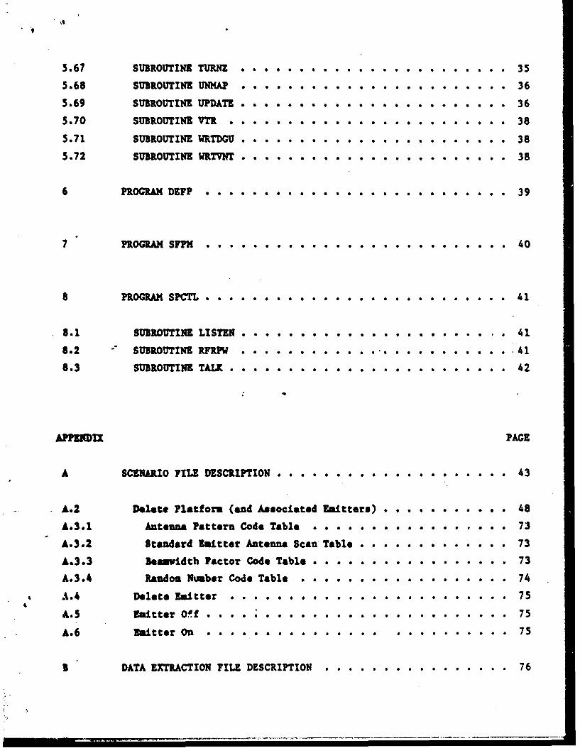
5.67 SUBROUTINE TURNZ . . . . . . . . . . . . . . . . . . . . . . . 35
5.68 SUBROUTINE UJNHAP • e * * * * .*. .a . . . . . . . . . . . . . . 36
5.69 SUBROUTINE UPDATE & . .* * .* . . . .* . . . . . . . . . . . . 36
5.70 SUBROUTINE VTR . . . . . . . . . . . . * 0 . * .. . .. .. 38
5.71 SUBROUTINE WRI•DCU . . .. . . . . . . . . . . . . . . . . . . . 38
5.72 SUBROUTINE WRTVNT ....... . . . . . . . . ........ 38
6 PROGRAM DEFP .... ..... .. . . . . . ...... 39
7 PROGRAM SFPM . . . . . . . . . . . ........... 40
8 PROGRAM SPCTL .e. . .a o o • . .*. . . . . . . . . . . .e * .. 41
8.1 SUBROUTINE LISTEN . * . . . . . .9. . . . . . . . .e * . . . 41
8.2 SUBROUTINE RFRPW * a o e o o o 9 9 9 o e .41
8.3 SUBROUTINE TALK • .* . . . . . .* . .. . . . . . . . . . . . 42
APPENDIX PAGE
A SCENARIO FX E DESCRPTON ..... ... . .... .o. ..... 43
A.2 Delete Platform (and Associated Emitters) . . . . . . . . . . . 48
A.3.1 Antenna Pattern Code Table . . . . . . . . . . . ...... 73
A.3.2 Standard Emitter Antenna Scan Table • . • . • • • ...... 73
A.3.3 Beanvidth Factor Code Table . . o • ............. 73
A.3.4 Random Nmber Code Table . . . . . . . . . . . . . . . . . . 74
A.4 Delete Emitter ..... . . . ................ 75
A.J Emitter OVf o .. . . . . . . . . . .. 75
A.6 Emitter On ..... . . . . . &.... 75
B DATA EXTRACTION FILE DESCRIPTION ................ 76

1.1Codes 1-6 ••. ••.79
1.2 Code 30 - Dropped Emitter 79
z.3 Code 31- Pulse Count Request Time Event ... a...... 79
a.4 Code 32 - Pulse Counts . . . . . , & . . . . .• 80
3.5 Code 33 - Record Platform Update ............... 81
3.6 Code 34 - Record Scan Update ..... 82
1.7 Code 64 - Start Scenario ....... 83
3.8 Code 65 - Stop Scenario ....... 83
1.9 Code 66 - Set Scenario Speed •.•.•...•. 83
3.10 Code 67 - Radiation Off # . , ..... 84
I11 Code 68 - Radiation On . . . • • • • • 84
3.12 Code 69 - Advance Scenario . . . . . . . . . . . . . . . . . . 84
3.13 Code 70 - Backup Scenario * . .*. . . . 9 * . a a 9 a e 9 * . * 85
1.14 Code 71 - Disable All DX Recording * a...•....... 85
3.15 Code 72 - Bnd Simulation Run .0. . .0 0 0 . . .0 .0 0 * .. 851.16 Code 95 - Maximum Pover Flie * .... . 86
3.17 -" Code 96 - Receiver Gain File ........ . .. • . 87
3.18 Code 97 - Receiver Sensitivity File ....... .... . . . 88
1.19 Code 98 - Azimuth Receiver Pattern File . . . . . ....... 89
3.20 Code 99 - Elevation Receiver Pattern File ........... 90
C DIGITAL SUBSYSTIM INTERFIACE .................. 91
C.1 Cousand Data • • • • • • .. .. . .. ........ 91C.1.1 h-itter Parameter Coumads . . . . ... 92
C.1-.2 System Covmands. , , , , , ..... , ......... . . 93
C.2 Status Data. • • • . • . ........... . • • • • • • . 93C. - Droppedhitter Number . . . . ......... .. 94
C.3 Pulse Counter. • • , . , . . . .......... . ..... 94
D TB - ASF NAVIGATION MESSAGE, ................ 95
S " TYPICAL SEC ONDTIMNG DIAGRAM . .. .. .. ... . .. . 98

SECTION 1
/ INTRODUCTION
The software for the Advanced Tactical Electronic Warfare Environment Simulator
(ATMIMS) resides in the Control Subsystem which includes a CPU With 124K word
memory, two 10 Kb moving bead disk drives, an operator console, a printer, and
interfaces to the TEZES Digital SubsystemLpt n udi C, and to a
renote simulation processor fpSe•rTaltu-*ppeudbrz-Y. The disk contains the
computer programs and test data. The data files include the Scenario files
4 -pi8Tfred-J•a Appem•w-" ch describe the environment to be simulated,
Maximum Available Power, Antenna Gain and Pattern and Threshold files (epee4e4d-•
'%4uAppeu iir - op6 ato..*-m* u1, and Data Extraction (DX) files pecil4ed6-
! n - S4d 9) which store scenario events as processed, operator actions and
simulator status information. The operator's console consists of a 24 line by
80 character CRT display and a standard keyboard. The console is used by the
operator to enter coands to control the simulation, iodify the scenario and
display status massages.
The ATIEZS real time software system consists of six separate programs designed
to operate under Digital Equipment Corporations's RSX-11M Executive. The
programs counicate by means of a system common area. The ATEWES software
maintains the Platform file, the Emitter file and various timing counters,
status flap and systm parameters. The real time software. provides all
operator comunications, as well as Scenario file input and event processing,
Wad DX file output.
The Platform file contains position, velocity, heading, bearing and range
attenuation parameters for up to 255 target platforms or sites and the platform
for the I9 systm under test. The Emitter file contains a platform link, an
emitter link, and power and scan parameters for up to 1,023 emitters. Once per
second the software updates the position of each platform and recalculates each
platforms bearing and elevation to the EW system and range attenuation. If ano
of these values has changed by an amount equal to or greater than the simulator
minimum change capability, an updated bearing, elevation, and attenuation will

. 4- .... •..•.......... .-.- . ...• - -t '"•"••tt3.
be output to the Digital subsystem for each associated emitter.
The Scenario file on disk contains a series of events In time order. Events
include the appearance of now platforms and emitters and changes in platform
motion and emitter status. Each event has a time associated with it which is
used by the program to process the event at the proper time.
Operator comands are included to initialize and start the simulation, stop the
simulation, speed up or slow down the scenario, set the scenario to a specific
time, turn radiation on or off, control the interface to the EW system under
tes"t and end the simulation rum. The operator cau also enter events to add to
or change the simulation as it is running.
While the simulation Is running the program records time tagged data on the disk
in a data extraction file. The data recorded includes each event and operator
comand executed, pulse count data and any error indicators from the digital
subsystem. The Data Extraction file cad be used by offline analysis programs to
evaluate the performance of the EW system under test.
The program also transmits a status message containing the position of the
platform for the EW system under test, and other status data to the remote
simulation processor upon request.
2

SECTION 2
SYSTEM ARCHITECTURE
The ATEWIS real time software is composed of six independent tasks which
communicats through system common areas. A simulation run is started by an
initialization program, IKIRN. This program requests and processes the data
necessary to Initialize the system. The program initializes the Digital
Subsystem and the system common area. INI•W then schedules the remaining real
time programs as needed and exits.
All operator interaction is provided by program OTASK, which is initiated by
INIRN. When OTASK is initiated, it prompts the operator to enter a command code
and is suspended by the Executive until a response is input. Based on the
c•mmand selected, the operator is prompted to enter any parameters needed to
defins thi command. When all data have been input, the command and its
parameters are stored In comon area OPERC. Program OTASK is then suspended
until the command has been processed. Upon restart, OTASK displays any error
code or display data returned by the processing programs and requests the next
command code.
Program RUALTh maintains a Platform File and an Emitter File in main memory.
The Platform File contains position, velocity, range attenuation, bearing, and
beading fields for up to 255 target platforms or sites and the platform for the
1W system under test. The Emitter File contains platform, power, and scan data
for eash sttesr. Once per second, the program viii update the position of each
- platform and recalculate its range attenuation, bearing, and elevation. If any
of these values has chansed by an amount equal to or greater than the simulator
mininm change capability, an updated bearing, elevation, and attenuation rill
be output to the Digital Generator for each emitter associated with the4
platform. Program REALTM processes all scenario events and operator commands.
All data to be output to the Digital Generator is formatted and output by this
program. I=ALTM also performs all Data Extraction file processing, including
reading and recording pulse counts as well as all other DX data.
3
I Program S$PM runs at an elevated priority. It performs all disc input for the
scenario file. Scenario buffers are maintained in a system common area.
Program DEF? also runs at an elevated priority. It performs all disc output for
the DX file. DX Buffers are maintained in a system common area.
Program STL performs all input and output for the HP 8566A Spectrum Analyer.
All command data are passed through common area ACTRL.
4

SECTION 3
PROGRAM INIRN
Program INIRN performs the functions necessary to initialize the system for a
new simulation run. This includes Initializing memory and initiating the
remaining real time programs. Program INIRN is the only real time program which
is directly initiated by the operator, done by encering & RUN INIRN command on
the operator's co:isole. The first action consists of terminating the remaining
real- time prograns. (ABRTR). This insures a normal startup even in situations
where the previous siuulation run was not terminated normally. This is
accomplished via an 1,SX-1LM Executive directive. Programs OTASK, RZALTM, SFFM,
DEPX, and SPCTL are aborted.
The operator is prompted to enter the Scenario file name to be used for the
current simulation run (GRAME). The Scenario file is located and the header
block is read (CTHDR). If the file is not found, the input request is repeated.
Otherwise, the Scenario file header Is displayed on the operator's console
(DISC!). The Scenario file header is used as the basis for the DX file header,
beginning by adding the Scenario file name to it.
Default values are provided for many of the initialization parameters through a
default data file. The file Is normally stored under the name DEFALT, and is
fully described in Appendix C of the ATEWES Operator's manual. The operator has
the option of entering a different file name from which to retrieve default
Initialization data (CRMAE). The initialization data are read from the
appropriate file (GDFLT) and displayed on the operator's console. The operator
then has the option of editing most of the default values. Editing is
accouplished by first displaying a single field, and then allowing the operator
to enter a new value using OPGII (integer values), OPGRI (real values), or GNAME
•' (file nmaes) with the edit mode enabled. The operator is then asked to enter a
code specifying either further edits, or acceptance of the initialization data
(OFGII).
When the initialization dats have been accepted by the operator, the
I5

-~ -- - - -- - - -. -
initialization is performed. The Power Boost, Frequency Dalsable, and Azimuth
and Elevation Receiver Pattern files are read into temporary storage (RDDAT).
The Maximum Available Power file is read into a work array (RDPINI). If any
errors are encountered such as a missing or incomplete data file, the operator
will still be prompted to enter a new file name as required. The Receiver
Antenna Gain file is read (RDINI) and combined with a 20 LOG(F) term and the
corresponding value read from the maximum Power file, as well as the Power Boost
for the current frequency.The result is stored as an integer in common area
OEiC. As the frequency is Increasing, data from the antenna pattern files are
used to determine pattern codes at 152 points over the frequency range.
The Receiver Sensitivity file in next read into the work array (RDINI). The
file represents the receiver antenna sensitivity and must be subtracted from the
corresponding Maximum Power file to determine threshold values, which are stored
In common area OPERC. The Max Power file is also stored in common area OPERC to
be used In realtime to compute received power vvlues.
If usage of IRI(-I time has been selected, the program checks to see that the
clock is on-line (TIRIC). If the clock does not respond, an error is output and
the the clock is disabled.
The DX file header is now completed. The simulation run time and date are
retrieved and inserted (FEDAT), and all initialization data file names are
stored (PHFIL). The DX file is created and the header is written to the first
block (CIDX). The remaininS realtime programs are initiated (START) and INIRN
exits.
-3.1 SUBROUTINE ART
Subroutine ABRTE Is used to terminate all ATEWES realtime programs. This is to
insure that all programs are intitiated normally at the beginning of each
simulation run. An RS-11M1 system directive is issued top abort OTASk, REALTH,
1FPM1, DIFP, and SPCTL. The routiuke delays 2 seconds to allow the aborts to take
effect and returns to the caller. This routine is stored in module INSBS.
3.2, SUBROUTINE CLDX
Subroutine CLDX in used to close the DX file after the header events are output.
6

The routine uses standard 1/O functions of the file system to close the file.
This routine is stored in module MINSBS.
3.3 SUBROUTINE CUDX
Subroutine CRDX is used to create a new DX file. The routine uses standard 1/O
functions of the file system to create a file with the fixed name
XXXECZ.m=;377. The initial size allocated to the file is deterrined by the
value in the default file. The routine then returns to the caller. This
routine is stored in module 143SB1.
3.4. SUBROUTINE GDFLT
Subroutine CDFLT is used to read all data from the default initialization file.
The file is accessed and read using standard Fortran formatted 1/O. If any
error is detected, or insufficient data is found, an error is output. The
routine then returns to the caller. Ths routine is stored I.n module INSBS.
3.5 SUBROUTINE GTMDR
Subroutine GTHDI is used to locate a selected Scenario file. The file is first
opened and the header read and stored for future use. The emitter map is then
read and stored in comon area OfERC. -If the file is not found, an error is
returned. The routine then returns to the caller. This routine is stored in
module I43NSS,.
3.6 SUBIRUTINE INIDS
Subroutine 1NIDS is used to initializs the Digital Generator. The DGU is first
checked that it is ready to accept comands from the control Subsystem (DGURDY).
All emitters are turned off, radiation is disabled, and the system under test
-mods is output. The routine then routine then returns to the caller,
3.7 SUIROUTINE RDDAT
Subroutine RDDAT is used to read all data from the receiver pattern, power boost
and frequency disable files. The files are accessed and read using standard
Fortran formatted 1/O. If any error is detected, or insufficient data is found,
an error is output. The routine then returns to the caller. Ths routine is
stored in module INSBS.
7

3.8 SJBROL•INE RDINI
Subroutine RDINI is used to read all data from the receiver sensitivity and max
power files. The files are accessed and read using standard Fortran formatted
1/0. If any error is detected, or insufficient data is found, an error is
output. The routine then returns to the caller. The routine is stored in
module INSIS.
3.9 SUBROUTINE RtRDY
Subroutine RMY is used to check the readiness of the RP Generator. A set of
frequency and DOA test points are read from files RFRDY.FRQ and RFRDY.DOA. A
simple emitter is programmed through each frequency and DOA combination. The
operator is notified of all failures. The operator has the option to continue
or exit if errors are detected.
3.10 SUBIOUTINE START
Subroutine START completes the initialization process begun by program INIRN.
The DU file-is first created using the size specified in the default file
(CRDX). The arrays in OPEKC are initialized using data previously calculated 'by
the main program. All remaining common data are also initialized. Programs
OTASI, REALTh, DZFP, SFM, and SPCTL ard initiated via an exetutive directives.
If all prosramw cannot be executed, an error is output and the program exits.
The proSran also initiates the situation display processor DISP is it is
installed. The routine then returns to the caller. This routine is stored is
module 1NSS.
3.11 SU•IOUTIUE Titl1
Subroutine T2111 is used to verify the readiness of the IRIC-B time code
generetor. The routine attempts to read the current time. An error code is
returned is the timeout expires before the clock responds. The routine then
returns to the caller.
8

SECTION 4
PROGRAM OTASK
Program OTASK provides all operator communications once the system has been
initialized for a simulation run. OTASK is scheduled by START vhen the
initialization process is complete. Program OTASK prompts the operator and then
accepts a command code response (OOII).If a menu request is specified, the
command menu is displayed (CHENU) and the next command is requested (OPGII).
If a system status display is requested, OTASK retrieves the system status and
displays the information on the operator's console (DSTAT).
If an enter now event command is specified, OTASK requests the event data from
the operator (EDTOT) and notifies RZALTh to process the data entered (OCNK).
If an error is returned, the operator may edit the event and retry (EDTOT).
If a display emitter command is specified, OTASK requests the emitter, retrieves
the parameters, and displays the inforation (DSPLY). If the data are edited to
"generate an emitter update, PEALTK is notified to process the now event.
Por SSP node systems, if an emitter sapping status display is requested, OTASK
retrieves the mapping status and displays the information on the operator's
console (DBIP).
Fr a display platform parameters, the operator is prompted to enter the desired
platform number. If the platform is inactive, or is the EW system platfora, an
error is returned. If a valid platform is requested, the REALTM program is
scheduled to return the display data(OCHND). The platform parameters are
formatted and output (LISPI). If more emitters are pending, a prompt is issued
to the operator. If a backup or gancel is entered, the program returns to the
caller. Otherwise, the REALTh program is rescheduled to get the next block of
emitters (OCIOND). This sequence continues until all emitters for the specified
platform have been processed.
9

For a display the active emitter iist request, the PEALTh program is scheduled
to return the first block of emitters for display (OCD). The emitter data are
formatted and output (LISEM). REALTM is then rescheduled to get the next block
of active emitters (OCMND). This process continues until all active emitters
have been processed.
For a display the active platform list request, the REALTh program is scheduled
to return the block of platforms for display (OCHND). The platform list is
formatted and output (LISA?).
'or all other commands, OTASK requests the appropriate command parameters
(OPCRI,OPGII), and notifies REALTh to process the data returned (OPCMD). Uron
restart OTASK checks the error flag, and displays an appropriate error messaca
if set (ERORS). If a display RF detector count or display pulse count command
vas specified, the return values are displayed. OTASK then requests the next
command code from the operator (OPGII).
4.1 SUBROUTINE •HENU
Subroutine CMENU is used to output the menu od ATEWES realtime commands. The ia
output and the routine returns to the caller.
4.2 SUBROUTINE DSPLY
Subroutine DSPLY is called to display and modify an emitter's parameters. Tht
emitter number is first requested from the operator (OPCII) and is placed in
OPERC. Program REALTh is notified to retrieve the linked platform parameterb
(0CMD). The associated platform's parameters are displayed (LISP). REALTH is
rescheduled to get the emitter data (OCND) which is displayed (ENEE). The
-operator is then asked if he wishes to edit the emitter's parameters (OPGII).
If no edit is specified, the routine returns to the caller. If an edit is
specified, a flag is set and the data is edited (ENEE). The edited date is
redisplayed, and the edit option requested from the operator. If a further edit
is specified, ENEE is invoked again with the edit flag set. When no further
edit is specified, REALTh is scheduled to process the update (OCMND) and the
routine returns to the caller.
10

4.3 SUBROUTINE DSPMPSubroutine DSPMP is used to retrieve emitter mapping status. The map is scanned
for all active operator emitters and their corresponding ATEWES DGU slot
numbers. This information is displayed on the operator's console as well as the
total number of DCU slots currently active. The routine then returns to the
caller.
4.4 SUBROUTINE DSTAT
Subroutine DSTAT is called to display the current system status. The REALTM
program Is first notified to retrieve the system status (GDATA). The elapsed
time, is converted from double integer to real (DFLT) and displayed. The EW
system platform data is output (LISP), followed by the number of active
platforms and emitters, and the scenario and RI status. Pulse count totals are
converted to reals (DFLT) and displayed, followed by the number of dropped
emitters. The routine then returns to the caller.
4.5 SUBIROUTINE DTOT
Subroutine EDTOT is used to enter or edit all data necessary to specify' a
scenario event. For a new entry, the event menu is output (EMENU) and the
operator is prompted to enter the event-type (OPCII). Based on the new event
type, or the event type being edited, the appropriate editing routine is called
as follows.
EVENT ROUTINE
1 ENPE
2 DPE
3 INEE
4 DEE
5 EOPE
6 ZONE
4.6 SUBROUTINE LISAP
Subroutine LISAP is used to output the ac.tive platform list. The number and
rangs for the first 80 platforms are unpacked and output. The operator is then
11.

prompted to enter a carriage return to display the next block of active
platforms. The cancel command may be used to terminate the display before the
entire list is output. When all active platforms have been displayed, the
routine returns to the caller. This routine is stored in module LISP.
4.7 SUBROUTINE LISEM
Subroutine LISKH is used to format and display the active emitter list. The
three state flags for each active emitter in the buffer are unpacked and
converted to their ASCII values (blanks or 0-On, I-Belov Horizon, D-Detectable).
The information is then output to the operator's console. The routine then
returns to the caller. This routine is stored in module LISP.
4.8 SUBROUTINE LISP
Subroutine LIST is used to display a set of platform parameters. Platform
parameters are unpacked (UNPK1) If the current platform is not the EW system
platform, the platform number, emitter number and platform flags are displayed.
In any case, platform position speed and heading are displayed. If this is not
the ZW system platform, the range attenuation, azimuth "and elevation AOA are
displayed. The routine then returns to the caller.
4.9 SUBROUTINE LISPI
Subroutine LISPI is used to format and output platform display parameters. The
platform position and velocity data are first output (LISP). The routine then
unpacks the frequency and pover for any active emitters returned by the REALTK
program. All emitters are displayed on the operator's console. The routine
then returns to the caller. This routine is stored in module LISP.
4.10 GUIROUTIE 0C00D
Subroutine OCND is used to schedule REALTM to process an operator command.
KTLAG is sat to cause REALTH to process the command residing in the EVENT
common. The routine vaits for event flag 33 to signify that processing is
complete and returns to the caller. For commands directed to the DISP program,
the nev display parameters are stored in common area OPERC and the mode flag is
updatted to flag the new data. The routine then waits for event flag 36 to
signify that processing is complete and returns to the caller.
12
- ,t -6,~a,•,J•'• • ..- e• ,. .4*" " - " 4-..... ...

4.11 SUBROUTINE SRICO
Subroutine VICO is used to control all opersator interaction with the HP 8566A
spectrum analyzer. The operator Is prompted to select the desired field or
commad (OPGII). For fields one through ton, the operator is prompted to enter
the data field to be transmitted. The data field Is formatted alo~o with the
appropriate command data for the spectrum analyzer. If no data--' * input,
the specified field io addressed for us* with the step up and 4' e s&
For a manual commnd the operator Is prompted to enter any 4I et,4 be
output to the spectrum analyser.
Tor on emitter tune command, the operator Is prompted to enter ~the desired
emitter number (OPGII). If the emitter is not active, an error Is ouatput and
the operator again prompted to enter the desired emitter number.
For an auto tame comand, the spectrum analyzer mode is set to auto tune -in
aoinn area ACTRL.
When all comiand data have been stored in common area ACTUL, the command in
passed to program REALT)( (OQ4ND)..
13

SECTION 5
PROGRAM REALTM
Program REALLT has three main memory files associated with it, in addition to
the Main Control Loop and processing segments. The memory files include the
Emitter File, the Platform File stored in system comon areas, and a Control
File. The processing sections include Initialization, Simulated Time,
Navigation Computer Output, Dropped Emitter Processing, Status Data Processing,
Command Processing, Platform Update, and Event Processing.
5.1 CONTROL FILE
The Control File is an internal memory file used by program RMALTM to store
status and timing data, as well as operator command parameters. The following
fields are included.
a. Su ted Time. 'A one word field containing the •iuulated time in
seconds since the start of the scenario.
b. Time Increment. A one word field containing the amount by which
Simulated Tine is incremented. This value is one when the scenario
is running at or slower than real time, and 8, 4, or 2 when the
scenario is running at 8, 4, or 2 times normal speed.
c. Next Ralf Second. A one word field containing the number of ticks
(sixtieths of a second) left in the current half second interval.
Decremented every tick and reset to thirty when zero is reached.
d. Simulatod Second Interval. A one word field coatainiu$ the
number of half seconds per Simulated Second. This value is one
* when the scenarior is running at or faster than normal, and 16,
8, or 4 when the scenario is !unning at 1/8 1/4 or 1/2 normal
* lspeed.
e. Next Simulated Second. A one word field containing the number
14
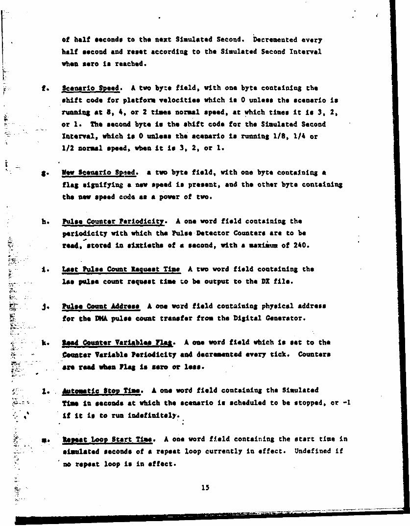
of half seconds to the next Simulated Second. Decremented every
half second and reset according to the Simulated Second Interval
when zero Is reached.
f. Scenario Speed. A two byte field, with one byte containing the
shift code for platform velocities which Is 0 unless the scenario is
running at 8S 4, or 2 times normal speed, at which tines It is 3, 2,
or 1. The second byte is the shift code for the Simulated Second
Interval, which to 0 unless the scenario is running 1/8, 1/4 or
1/2 normal speed, when it is 3, 2, or 1.
gI. New Scenario Speed. a two byte field, with one byte containing a
flag signifying a now speed is present, and the other byte containing
the neo speed coda as a power of two.
h. Pulse Counter Periodicity. A one word field containing the
periodicity with which the Pulse Detector Counters are to be
read, stored In sLxtieths of a second, with a maximnm of 240.
Lo. Lst Pulse Count Request T.us A two word field containing the
Is* prlse count request tbie to be output to the DX file.
J. P.INee Count Address A one word field containing physical address
for the WA pulse count transfer from the Digital Generator.
k. Read Counter Variables Flat. A one word field which Is set to the
Counter Variable Periodicity and decremented every tick. Counters
ar read wben a Is sere or less.
1 t. unage Otg Tine. A on* word field containing the Simulated
-Time in seconds at which the scenario is scheduled to be stopped, or -1
If It is to run indefinitely.
" . tsel9_t Loop Start Tine. A one word fiteld containing the start time in
simulated seconds of a repeat loop currently in effect. Undefined if
no repeat loop Is in effect.
15

n. Repeat Loop Stop Time. A one word field containing the stop time in
simulated seconds of a repeat loop currently in effect, or -1 if no
repeat loop is in effect.
o. RY Status. A two byte field containing a flag shoving the current
status of the RY radiation and a flag shoving the last operator
status set.
p. Scenario Status. A two byte field containing a flag shoving whether
the scenario is currently running and a flag shoving whether the
scenario has ever been started.
q. �ezt Scenario Event. A four word field containing the event nuaber,
time, and memory location, and length of the next event of the scenario
file.
r. Current Event A two word field to contain the numBer of the event
and length of the event currently being processed. Event number
set nagative when processing operator events.
as Xmitter PIS lask A one word field containing the operator's flag
for emitter file entries vhen an operator event is being processed.
t. Platform F7lA Mask A one word field containing the operator's flag
for platform file entries when an operator event is being processed.
- Z.te l•a•. A one word field which Is set to zero each time
Simulated Time is incremented, and set to -1 each time an Update is
performed.
v. IS Platform Index. A one word field containing the index address
in the Platform File of the EW system platform.
v. BW Eeadl% A one word field to contain the heading of the EW" system.
16

X. RV Climb LAnle A one word field to contain the climb angle of theXVsystem.
ye ,V Position A isi word field to'contain the position of the 1W system
scaled for usage by the line of sight calculation.
as Regqest Pulse Count. A one byte field set to one when a Pulse
Count display is requested and cleared when completed.
&a. System Controls A one word field containing the current
"*DOA test pain., system test mode, and RI status command. Output to
the Digital Generator once per second.
ac. Number of Dropped Emitters. A one word field containing the
number of dropped emitters since the last system status display.
ab. Last Dropped Emtter A one word field to contain the latest dropped
emitter read from the Digital Cenerator.
ac. Latest Pulse Counts. Three tvo word fields coutaining the latest
totals of pulse counts for all 1023 emitters in the currently
active modes.
ad. Risal Ties Display Filters. A eight word field containing an
attenuation high and low limit, a bearing upper and lower
limit, and a frequency upper and lover limit (two words each).
Limlts are used for the System Status Display in
determining the filtered number of active platforms and emitters.
as. Last Display Platform - One word field containing the last
platform number processed by the Display Platform command. Used
when returning successive blocksof emitters for platforms with more
than 64 linked emitters.
sf. 'Last Displayed Emitter - One word field containing the next emitter
number to return for the platform stored in LPLAT. If negative,
17

- -~r . . • ... • • •L . *-,• S • . h X * *. .- ' '• 7- *. . .* * N. • .- L C' " - N "o " .. "N ¾ N . A'.
all emitters for the platform have been displayed.
&S. Number of Active Emitters A one word field containing the number of
currently active amitters.
ah. Number of Active Platforms A one word field containing the number of
currently active platforms.
&I. Tune Next Emitter A one t:ord flag set not zero when it is time to
auto tune the spectrum analyser to the next active emitter.
aS. Pooling Status A two word field to contain the pooling status of
all Rf channels. One word contains the initial status as specified
by the default file. The other word contains the current status,
including changes required by dedicated emitter assignments.
ak. Dedicated Emiter Count An eight byte field containing a one byte
count of the number of emitters currently dedicated to each RP
channel.
al. Last Sync Emitter A one word field containing the last emitter
specified as the scan sync emitter.
am. DX Event Buffer A 256 word field used to build DX events. Used for
platform update events, scan update events, and pulse count events.
5.2 NOMITR (CONTROL LOOP)
.The Control Loop manages the execution of all of the processing subsections.
11gh priority tasks are given preference by placing them near the beginning of
the loop. The following cycle is continually executed searching for the next
task to be processed.
a. Perform system initialization 'INITT). This task ii performed only
once at progrem initiation.
b. Wait for event flag 40 to be set, either by the clock routine or
18

by program OTASK.
c. If the last dropped emitter number read by the clock routine is
non-zero, execute dropped emitter processing (DREM).
d. Record pulse counts in the DZ file if a DMA transfer has
completed (ERPC).
t. If the spectrum analyzer auto tune flag is set, process the next
emitter for tuning (SPNXT). If an emitter is processed, control
.is rieturned to point c. Otherwise, execution continues at point f.
f. If simulated time has reached the Automatic S-op time, record a
Stop Scenario event in the DX file (RECST).
g. If Simulated Time has reached the Repeat Loop Stop Time, Backup and
Start Scenario Commands are executed (REITL).
h. Process the next operator command if the command flag iu OFERC
is set (OEV). ft
i. Update platform positions if the Update Flag Is set (UPDATE). If an
Update is performed, control is returned to point c. If no Update
Is performed, execution continues at point J.
S. It the time of the next scenario event stored in the Control File is
lose than or equal to Simulated Time, aid the scenario has been started
at least once, the eve-at is executed (SCEINEV). If an event is processed,
execution continues at point c. If no events are processed, execution
continues at point b.
5.3 CLZAST (TIMING CONTROL)
Progra. timing is achieved through the use of an Asynchronous System Trap,
(AST). in AST is scheduled to occur 60 times a second, and each time an AST
occurs the program is interrupted and control is passed to a timing control
19

IL
section. This routine then performs all timekeeping functions. Appendix E
contains a diagram of the scheduling of specific processing vithin a I second
interval.
For each AST, the latest System Controls command is issued and the return data
(the latest dropped emitted) is stored for use by the main control loop.
Elapsed time is incremented by one. If spectrum analyzer auto tuning is active,
tlýe next tune time is decremented, and the Tune Next Emitter flag is set if the
result s zero. The Read Counter Variables flag is decremented. If the result
is zero, and the previous pulse count data has been processed, the counter is
resqt and a pulse count transfer is initiated. The pulse count request time is
read and stored (GDXTH). The Next Half Second count is decremented. If the
result is not zero, processing is complete. Othervise, the count is
reinitialized and the the Next Simulated Second count is decremented. If the
result zero, Simulated Time is updated. If a the new scenario speed flag is
set, control variables are updated using the new speed value. If the next
Simulated Second will occur in .5 seconds, the Update Flag is set so that the
Update begins .5 seconds before the actual time is readhed.
5.3 SUBROUTINE ADVSCN
Subroutine ADVSCN is used to process an Advance Scenario operator command. The
advance time is firs tied that it Is greater than the current simulated
time. If it is not, an error is returned and the routine returns to the caller.
If the advance time is valid, the scenario stop time is set to the current time,
and the routine waits for the scenario to be stopped. When the scenario has
heen stopped, a Stop Scenario event is recorded in the DX file (RICST),
radiation is turned off, and the Advance Scenario command is recorded in the DI
file (WRTMT). All scenario events up to and Including the advance target time
are then executed. Platform positions are updated locally as time is advanced.
When the target time has been reached, a normal platform update is performed to
update all range, bearing, and elevation data (UPDATE). Radiation is then
turned back oi if it was enabled before the start of the advance command. The
routine then returns to the caller.
20

5.5 SUBROUTINE ATAN
Subroutine ATAN is used to compute the arctangent of an angle. The arctan
funticon is determined using a binary search of a tangent table. The angle is
not adjusted for quadrant effects. The routine then return@ to the caller.
This routine is stored in module FANGL.
5.6 SUBROUTINE BACXL
Subroutine BACKL is used to backup the scenario after it has been stopped. The
platform file ts reinittalLsed (INI1F), all emLtterd are deleted and turned off
In the Digital Generator, and the EV system position is reinitialited (INEW).
The soenarlo file is then reinitialized (111SCN). The scenario is then advanced
to the backup target time using the sase procedure as the Advance Scenario
eomnand. The routine then returns to the caller. This routine is stored in
module ADVSCII.
5.7 SUBROUTINE BACKUP
Subroutine BACKUP is used to process an Backup Scenario operator coumnand. Thebackup tim is first verified that it is loes than the current simulated time.
If it is not, an error is returned and the routine returns to the caller.
If the backup time is valid, the scenario stop time is set to the current time,
and the routine waits for the scenario to be stopped. When the scenario has
been stopped, a Stop Scenario event is recorded in the DX file (RECST),
radiation is turned off, and the Backup Scenario command is recorded in the DX
file (VRTVRT). The scenario is then backed up to the target time (BACK!.). This
routine is stored in module ADVSCN.
3.8 BUSIOUTU• CIyIL
Subroutine CIFrL is used to cheek an emitter against the current system status
display filters. The frequency is read back from the DLiital Generator and
compared aSainst the filter limits. The carry bit is set if the emitter lies
' outside the limits. otherwise, the carry bit is clear upon return. The routine
then returns to the caller.
5.9 SUBROUTINZ CKDED
Subtbutine CKDED is used to update the pooling status as dedicated emitters are
21
,.* * * * * **I
- *I... . .
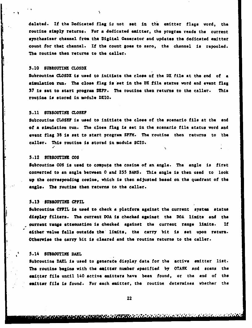
deleted. If the Dedicated flag lo not set In the emitter flags vord, the
routine simply returns. For a dedicated emitter, the program reads the current
synthesizer channel from the Digital Generator and updates the dedicated emitter
count for that channel. If the count goes to zero, the channel is repooled.
The routine then returns to the caller.
5.10 SUBROUTItE CLOSDX
Subroutine CLOSDX is used to initiate the close of the DX file at the end of a
simulation run* The close flag is set in the DX file status word and event flag
37 is set to start program DIFP. The routine then returns to the caller. This
routine is stored in module DXIO.
5.11 SU•UOUTINE CLOSE?
Subroutine CLOSEF is used to initiate the close of the scenario file at the end
of a simulation run. The close flag is set in the scenario file status word and
event flag 38 Is set to start program SFPM. The routine then returns to the
caller. This routine is stored in module SCIO.
5.12 SUB ROUTINE COS
Subroutine COS is used to compute the cosine of an angle. The angle is first
converted to an angle between 0 and 255 SAMS* This angle is then used to look
up the corresponding cosine, vhich is then adjusted based on the quadrant of the
"aSloe. The routine then returns to the caller.
5.13 SUBROUTINE CPFIL
Subroutine CIVIL is used to check a platform against the current system status
display filters. The current DOA is checked against the DOA limits and the
c- ourrent range attenuation is checked against the current range limits. If
- either value falls outside the limits, the carry bit is set upon return.
Otherwise the carry bit is cleared and the routine returns to the caller.
55.14 SUBROUTINE DAEL
Subroutine DAEL is used to generate display data for the active emitter list.
The routine begins vith the emitter number specified by OTASK and scans the
emitter file until 140 active emitters have been found, or the end of the
emitter file is found. For each emitter, the routine determines vhether the
22

linked platform Is above or below the radar horizon, whether the emitter is on
or off, and whether the emitter is detectable or not. These flags are packed
with emitter nuamber in the return buffer. When the buffer is full, or the end
of the emitter file Is reached, the routine returns to the caller.
5.15 SUBROUTINE DAPL
Subroutine DAPL is used to generate data for the active platform list. The
routine begins with the first entry in the platform file and scans the entire
file for active platforms. The IW system platform is excluded, as well as any
platform whose range or AOA lies outside the current limits for the system
status display. For each active platform within the limits, the routine returns
the platform number and the range attenuation. When the end of the platform
file Is reached, the routine returns to the caller.
5.16 SUBROUTINE DEE
Subroutine DM is used to delete an emitter from the simulation. The emitter
number Is first mapped to Its corresponding Digital generator slot number. The
link to the associated platform is deleted. The all emitter slots are turned
off in the Digital Generator (DELIM), the event is recorded in the Dz file
(WITWUT), and the routine returns to tha caller.
5.17 SURIOUTUIW DEIM
Subroutine VXI is used to reinitialize emitter slots as they are deleted. The
routine first checks the pooling status of the emitter to be deleted (CKDED).
The slots are then turned off in the Digital Generator and the emitter file
etries for the associated slots are reinitialized. The routine then returns to
aJs cller. This routine is stored in module DX.
5.18 BUBIOUTINI PU7
Subroutine DCVII is used to send a series of commands to the Digital Generator.
tach command is output (VKTDGU) and the routine returns to the caller.4
5019 SUIROUTINE DPS11T
Subroutine DISMIMT Is used to Sather platform and emitter parameters for real
time display. The routine first determines which platform the emitter is
associated with. The platform is then reconstructed as an enter new platform
23

event in scenario format. The routine then sands this data to be displayed and
waits (STOT).
Upon restart the emitter Is reconstructed as on enter new emitter event in
scenario format from information in the Digital Cenerator and the Control
Computer. The routine then returns to the calling routine.
5.20 SUBUDOUTI DPLC
Subroutine DPLC Is used to process an operator request to display pulse counts
for an emitter. The routine first checks that the requested emitter is active,
and returns an error if it is not. If the emitter is active, the emitter number
is stored in the lequest Pulse Count flag. If the scenario has been started,
the routine returns to the caller. If it has never been started, all zero pulse
counts are returned and OTASM is notified of command completion (STOT). the
routine then returns to the caller. This routine is stored in module PLSCNT.
5.21 SUBROUTINZ DPE
Subroutine DPE is used to delete a platform from the simulation. If the
platform is not active, or is the EW system, an error is returned. Otherwise
the platform is marked as inactive, and8all linked emitters are also deleted
(DELSI4), The event is recorded in the DX file (WRTVNT) and the routine returns
to the caller.
5.22 SUBIROUTINE DPLAT
Subroutine DPLLT is used to process a Dieplat Platform operator command. If the
platform is Inactive, or the SW system platform, an error is returned. For a
valid platform, the position and velocity parameters are retrieved from the
platform file. The platform number is then checked to see if it is the same as
the last displayed platform. If this is the same platform, the next emitter to
display is checked. If the next emitter to display is no longer linked to this
platform, or is negative, the emitter list begins with the first emitter on the
platform. Otherwise, the first emitter returned will be that stored in common.
for a new display platform, the first linked emitter is always the first
returned. Starting with the appropriate linked emitter, the routine formats
emitter number, frequency, and effective output pover into the return buffer for
up to 64 emitters. The last displayed platform number and next emitter number
24

are updated. The routine then returns to the caller.*
5.23 StBIROUTINE DREH
Subroutine DREM procesed the latest dropped emitter number read from the Digital
Generator. If the number is zero, the routine simply returns. For a non-zero
dropped emitter number, the emitter first determines the first slot number which
Is part of the operator emitter. The slot number is then mapped back to the
corresponding operator emitter number (UNKAP). The emitter is then turned on or
off based on its status as stored in the emitter file. The operator emitter
number and Digital Generator slot number are recorded in the DX file (WRTVWT).
The LAst Dropped Emitter number Is cleared, and the routine returns to the
caller.
5.24 SUBROUTINE DSBDX
Subroutine DSBDX is used to process an operator Disable DZ Recording command.
The command Is first written to the DX file (WRTVNT). The Disable DX Recording
flag Is set ant the routine returns to the caller.
5.25 SUBIROUTINE ENDSIM
Subroutine ENDSIN is used to process an End Simulation operator command. RF
radiation is turned off and the command is recorded in the Dx file (WRTVNT).
The Scenario File to be closed (CLOSEU) and the DI file is closed (CLOSDZ). The
exit flags are set for the situation display processor and the spectrum analyzer
"control program. The routine then sets event flag 51 to restart the ATEWS
Executive Menu program and exits.
-5 S26 8U•OUTINE ahm
-Subroutine EME is used to an enter/update emitter event. The routine first
verifies that the emitter's platform is active and not the EW system. The first
bas frequency is check against the Frequency Disable Pile. For an update
emitter event a test is made to insure the emitter Ls active. A failure on any
of the initial status checks generates an error message and returns to the
calling routine.
For an operator enter new event the number of unused scenario slots is compared
to the number required. If not enough slots are available an error message is
25
displayed and the routine returns to the caller.
An operator update emitter event cannot use more DGU slots than the number
currently Is use by the emitter. Otherwise, an error message is displayed and
the routine returns to the caller.
Some eamtter update events require the emitter to be turned off before updating.
Any emitter with a sync emitter link or any edit to an emitter with a sync
emitter link must be turned off.
A bqffer is built from the non-repeated event fields and the first set of the
repeated fields. This buffer completely defines one DGU slot emitter, except
for the linking code (See Appendix C.1). The buffer is output to the Digital
Cenerator (DGOUF).
For an emitter using more then one DGU slot only the repeated fields are changed
in the buffer before it is output again.
eased upon frequency the chirp rate field is scaled to correspond to maximum
chirp attainable in the frequency synthesizer, See Table I in Appendix A.
Emitter linking code is determined based upon dependent signal status, Emitter
Link Select (ELS), Link Seed Jitter Code (LSJC) and PRI. Dependent Signal
eitters utilize the sync emitter link exclusively. A DGU slot with a non-zero
ELS would have a sequence link of its own slot number and pattern switch link of
the next slot number. the last slot would pattern switch link the first slot.
A DOU slot with a non-zero LSJC will sequence link the first slot.
The remaining DGU slots sequence the next slot until the end of the chain which
sequence links the first slot. DGU slots with a FRI less than 2 microseconds
are the exception. these slots can only be generated using the sync emitter
link. Thus the slots with a FRI 2 microseconds or greater are sequence linked
together and the others are sync emitter links from these slots.
5.27 SUBROUTINE ENPE
Subroutine ENPE is used to process an enter new platform scenario event. The
26

routine first determines whether the event is a new platform, velocity change,
reposition or turn event.
For a new platform event, the routine returns an error if the platform is
already active. Otherwise the positions and velocities are stored in the
platform file for the specified platform. The initial range (FNDRA), bearing
(MIDE!), and elevation (IMDEL) to the IW system are calculated and stored in the
platform file. If an operator event is being processed, the operator's flag is
set in the platform file. The event is written to the DX file (WR7VNT) and the
routine returns to the caller.
For a velocity change, reposition, or turn event the routine returns an error if
the specified platform Is inactive. If the platform is active, new positions,
velocities, or turn data are stored in the platform file. The heading and pitch
change flags are set whenever different values are stored. The operator's flag
is set if an operator event is being processed, the event is written to the DX
file (WIVRTM), and the routine returns to the caller.
S.28 SUEROuTIU so0nSubroutine BO33 is used to process an eiitter off scenario event. The routine
returns an error if the specified emitter is inactive, or if a scenario event
attempts to turn off an operator's emitter. Othervise the emitter is mapped to
its corresponding Digital Generator slot number. Each slot usec to simulate the
emitter is turned off, the event is written to the DX file, and the routine
returns to the caller.
5.29 SuUOUTINE 30,3
- Subroutine EONE is used to process an emitter on scenario event. The routine
returns an error if the specified emitter is inactive, or if a scenario event
attempts to turn on an operator's emitter. Otherwise the emitter is mapped to
its corresponding Digital Generator slot number. Each slot used to simulate the
emitter is turned on, the event is. written to the DX file, and tha routine
returns to the caller.
5.39 SUBROUTINo• WDE
Subroutine MIDE is used to compute the true bearing from a platform to the EW
27

system platform using the following formula.
Bearing - Arctan (X -X ) / (Y -Y )
Delta X and delta Y are used to compute the tangent of the bearing angle. The
angle is then determined by taking the arctan of the resultant tangent (ATAN).
The angle is then adjusted for the right quadrant. The true bearing is the
combined with platform heading to cumpute the relative bearing from the current
platform to the IV system platform. The routine then returns to the caller.
This routine Is stored in module FANGL.
5.31 SUBROUTINE FNDEL
Subroutine FNDEL is used to compute the true elevation from a platform to the EW
system platform using the following formula.
2 2 .5Elevation - Arctan (Z-Z ) /((XX) + (Y ) )
p 0 p@ 0p0II
Delta X, delta T, and delta Z are used to compute the eangent of the elevation
angle. The angle Is then determined by taking the arctan of the resultant
tangent (ATAM). The angle is then adjusted for the right quadrant. The true
elevation Is the combined with platform pitch to cumpute the relative elevation-from the current platform to the EW system platform. The routine then returns
to the caller. This routine is stored in module FANCL.
5.32 SUBROUTINE INMSubroutine MNDRA is used to determine the current range attenuation for a
pftform. A hortson check is performed for each platform if the line of sight
check is enabled. The maximum separation is computed from the altitude of the
IV system and the altitude of the current platform. If slant range squared
exceeds the maximum allowable range, the range #ttenuation is set to the maximum2value (127). Otherwise SR is then used in a binary table search to determine
0 , the Platform Range Attenuation. The routine then returns to the caller.
5.33 SUBIROUTINE GDXT4
Subroutine GDXTM is used to determine the recording time for a DX event. If the
IR16-G clock is disabled, the current elapsed time tick count is returned.
28

Otherwise the routine reads the current time of day from the IRIG-B time
"generator. The routine then returns to the caller.
5.34 SUBROUTINS GSTAT
Subroutine CSTAT is used to process an operator system status display request.
The SW system platform parameters are first copied to the return buffer,
followed by the range and bearing filters. The number of active platforms, and
detectable emitters both filtered and unfiltered are determined and copied to
the return buffer. The elapsed time, scenario time and status, and RPF status
are copied to the return buffer. The latest pulse count totals are copied. The
dropped emitter count is copied to the buffer, and the count is zeroed. The
routine then returns to the caller.
5.35 SUBROUTINM INJII
Subroutine M)41EW is used to Initialize the EW system platform. The platform is
marked as active, and as the KU system. All position and velocity fields are
zeroed and the platofru is linked to emitter zero. The routine then returns to
the caller. This routine is stored in nodule InITT.
5.36 SUIBROUTUII IIPIP.
.. Subroutine IIIP? is used to initialize the platform file. All platforms are
:awrked as inactive. The flert emitter link is initialized to show the end of
the link, and the routine returns to the caller. This routine is stored in
moudule INlTT.
5.37 SUIROUTINI 1SCM
Subroutine 111SCR is used to initialise the scenario file. The file is first
"- et to the beginning of the file (RESETY). All events scehduled to occur at
time zero are then executed (SCENIV) and the routine returns to the caller.
3.38 SU•ROUTTINE INITD
Subroutine INITD is used to initialize DX file access for program REALM. The
buffer pointer is set to the beinnting of the first DX buffer. All Dx buffers
aze marked as free, and the routine returns to the caller. This routine is
#toaed in module DXIO.
29

5.39 SUPROUTI1N INIT?
Subroutine INIT? is used to initialize scenario file access for program REALTH.
The buffer pointer Is initialized to the beginning of the first buffer. The
routine vaits for the first scenario buffer to be filled and returns to the
caller. This routine is stored in module SCIO.
3.40 SUIROUTINZ INITT
Subroutine IITT performs all initialization for the initial startup of program
RZALTH. The virtual address of the pulse count Wk buffer is converted to a
phisical address (VTR). The scenario file is opened for read (INITF) and the
Dato& Btraction file is opened for append (INITD). Dynamic memory mapping is
initialized (HPIN).
The platform file is initialized (IIPF), and all emitters are deleted from the
Knitter File and turned off in the Digital Generator. The EW system platform is
Initialized (XNM). All parameters in the Control File are initialized and the
routine returns to the caller.
5.41 SUMRUTINE LOTIM
Subroutine LOTIM is used to output the current scenario time to the Digital
Generator. The time is first broken down into its hours, minutes and seconds
components. These values are then converted to ZCD and output to the Digital
generator. The routine then returns to the caller.
5.42 SUBROUTIPM HPDF
Subroutine HFDF is used to map virtual address space to the Display File stored
in coeon DWILE. If comon EFILE is sapped on entry, it is unmapped. The
- routine then returns to the caller. This routine is stored in nodule HAPSUB.
5.43 SUBROUTINE •HP•
Subroutine MPEF is used to map virtual address space to the Emitter File stored
in comon EFILI. If common DFILE is mapped on entry, it is unmapped. The
routine then returns to the caller. This routine is stored in module MAPSUB.
3.44 8UBROUTINE MPINI
Subroutine MPIRI is used to initialize dynamic mapping for common areas DFILE
30

and EFILE. The Active Page Register is computed from the virtual address
assigned. The DFEF region is attached and the EFILE portion is mapped. If any
errors are encountered, the routine outputs an error message and exits. This
routine Is stored in module KAPSUB.
5.45 SUBROUTINE RAVAST
Subroutine NAVAST is used to create and output the TEWES Navigation message, in
Appendix D. The routine is started when a one byte request is issued across a
RS232C serial port. The current contents of the five processing registers is
saved on the stack. The message is built and a checksum is generated. The
checksum is the exclusive or of all data bytes in the message. The message is
output over the same serial port.
5.46 SUBROUTINE 0PEV
Subroutine OMEV is used to process an operator command. The routine initializes
the return error code, the current event number, and the emitter and platform
flaS masks if an operator entered scenario is being processed. The routine then
decodes the command code and jumps to the appropriate processing subroutine.
Unless the last command vas a pulse count request, the current scenario time is
returned, OTASK is notified of. coumabd completion (STOT), and the routine
returns to the caller.
5.47 SUBROUTINE RELVNT
Subroutine RELVNT is used to return the next event from the scenario file. If
all scenario input buffers are empty, the routine returns an event code of zero.
Othervise the next event in the scenario is returned and buffer pointers are
updated. The routine then returns to the caller. This routine is stored in
module SCIO.
5.48 SUIROIJINE REPC
Subroutine REPC is used to record the latest pulse count data in the DX file.
If the latest pulse count request time is not zero, it is recorded in the DX
file (WRTVNT) and reinitialized to zero. If a pulse count transfer has been
completed, the pulse counts for all active emitters are formatted and recorded.
For each active entry in the emitter map, the pulse counts are indexed by
Digital Generator slot number. The counts for all emitter slots used to
31

3enerate the emitter are totaled. If an overflow occurs for a patricular pulse
count type, the total is set to the maximum value. Pulse count events are
formatted with operator emitter number, followed by the total for all three
pulis count types. Emmitter reports arre packed to a maxiuum event length of
256 words and output to the Dx file (WRTVNT). The routine then returns to the
caller. This routine is stored in module PLSCNT.
5.49 SUBROUTINE REPEAT
Subroutine REPEAT is used to process an operator Initiate Automatic Repeat Loop
€omsand. The Start and Stop Times specified with the command are stored in the
Control Pile. The scenario is advanced or backed up as needed to the Start
Time. The scenario is then started and will automatically be executed between
the Start and Stop Times until a Stop, Advance, or Backup Scenario Command is
given.
5.50 SUBROUTINE REPTL
Subroutine REMTL is used to initiate the next pass for an automatic repeat loop.
The scenario is backed up to the repeat loop start time (BACKL). The scenario
is then started, and scheduled to stop at the repeat loop stop time. The start
command is recorded in the DX file (WRTMVNT), and the routine returns to the
caller. This routine is stored in module REPEAT.
5.51 SUBROUTINE RESEFT
Subroutine RESETW is used to reset the scenario file to the beginning. The
reset scenario flag is set and the routine waits for the first scenario buffer
to be filled. The buffer pointer is initialized and the routine returns to the
caller. This routine is stored in module SCIO.
5.52 SUBROUTINE RICK
Subroutine RICHK is used to set the Rf status to the last status set by the
operator. If the last operator status set yas enabled, the RF enable flag is
set in the System Controls word in the control file. Otherwise the flag is
cleared. The routine then returni to the caller. This routine is stored in
module RIPCON.
32
5.53 SUBROUTINE RFOFF
Subroutine RFOFF is used to process an operator Disable Radiation command. The
IF Status is updated in the Control File, and the event is recorded in the Data
Extraction File (WRTVNT). The routine then returns to the caller. This routine
is stored in module RFCON.
5.54 SUBROUTINE RFON
Subroutine RFON is used to process an operator Enable Radiation command. The RF
status Is updated in the control and the event is recorded in the DX file
(WRTVNT). If the scenario has never been started, the elapsed time counter is
started (STRTC). The routine then returns to the caller. This routine is
stQerd in module RFCON.
5.55 SUBROUTINE SCENEV
Subroutine SCENEV is used to process a single scenario event. If the last event
read from the scenario is type zero, the routine attempts to get the next event
from the file. If a zero is still returned, the routine returns to the caller.
Otherwise the event time is copmared to the current 'time, and the routine
returns to the caller if the event time is greater. Otherwise, the current
event and platform and emitter masks are initialized in the control file and the
appropriate event processing routine is called. The routine then releases the
next event from the scenario file (RELVNT) and returns to the caller.
5.56 SUBROUTINE SDFIL
Subroutine SDFIL is used to process an operator Set System Status Display
filters command. The new display filters are stored in the Control File, for
use by all succeeding display commands. The routine then returns to the caller.
5.57 SUBROUTINE SETCP
Subroutine SETCP is used to process an operator Set Pulse Counter Periodicity
command. The new periodicity is stored in the Control File and the routine
returns to the caller. This routine is stored in modulc PLSCNT.
5.58 SUBROUTINE SEDA
Subroutine SETDOA Is used to process an operator Set DOA Test Point command.
The'old test point is cleared from the current system controls. The new test
33

point is then merged with the remaining system controls. The routine then
returns to the caller.
5.59 SUBROUTINE SKTSPD
Subroutine SETSPD is used to process an operator Set Scenairo Speed command.
The New Speed Flag is set and the speed code is stored in the Control File, to
be implemented by the timing routlne at the next Simulated Second.
5.60 SUBROUTINE SIN
Subroutine SIN is used to compute the sin of an angle. The angle is decreased
by 256 BAKS and the cosine of the result is computed (COS). The routine then
returns to the caller.
5.61 SUBROUTINE SPNXT
Subroutine SPNXT is used to process the next emitter for automatic tuning of the
spectrum analyzer. The routine first checks that there is at least one active
emitter, and returns If there are none. If there are any active emitters, the
routine searches the emitter file biginning at the "last emitter which was
autonaticolly tuned. When an active emitter is found, the DOA test point is
automatically set based on the POA of the linked platform. The routine then
reads the emitter's FRI, scan type, scan rate, frequency, frequency agility, and
frequency modulation amplitude from the Digital Generator. These values are
stored in common block ACTRL and event flag 42 is set to start program SPCTL.
The routine then returns to the caller. This routine is stored in module SPfThf.
5.62 SUBROUTINE SFRTL
Subroutine SPRTH is used to process an operator Spectrum Analyzer control
. €omand. The routine first waits for the spectrum analyzer busy flag to be
cleared. For an emitter tune command, the routine first checks to see that the
emitter is active, and returns an error if it is not. If the emitter is active,
the routine loads the required data for the tune command (SPNXT) and returns to
the caller. For a manual spectrum analyzer command, the routine sets event flag
42 to start program SCTL, sets the spectrum analyzer busy flag, and returns to
the caller.
34
5.63 SUBROUTINE STCEN
Subroutine STCEN is used process an operator Start Sceaario command. The
Scenario Status is first checked to see if the scenario has previously been
started. If so, the Scenario Status is updated to show the scenario running.
The timing routine will then automatically begin updating Simulated Time, and
real time processing will take place. If the scenario has never been started,
all events at time zero are executed (INISCN) and the AST request is initiated
(STRTC). The radiation is turned on unless a Radiation Off command has been
processed (RFCK). If a stop time has been included, the value is stored as the
Automatic Stop Time in the Control File. If no stop time is specified, this
value is set to the highest possible number so the scenario will run
Indefinitely. The event is written to the DX file (WRTCNT) and the routine
returns to the caller. This routine is stored in module SCCON.
5$.64 SUBROUTINE STOT
Subroutine STOT is used to notify program OTASK of command completion. Event
-flag 33 io set to notify OTASK of the completion status. The routine then
returns to the caller-
5.65 SUBROUTIW STPSC"
fubroutine STISCNIis used to process an operator Stop Scenario command.* The
current Simulated Time ts placed In the Automatic Stop Time field in the Control
File. The Repeat Loop Start and Stop Tines are reinitialized. The routine then
returns to the caller. This routine is stored in module SCCON.
5.66 SUBROUTINE STTC
Subr.outine STRTC is used to perform initial scenario startup processing. A
pulse count transfer Is initiated to clear all counters in the Digital
Geerator. The initial clock AST is requested and the scenario status is
updated. The routine then returns to the caller. This routine is stored in
module SCCOI.
5.67 SUBROUTINE TURNZ
Subroutine TURNZ is used to update a platform which is executing a turn. The
turn rate is scaled by the current scenario speed and added to the the platform
headinS. The resultant heading is scaled to BAMlS and compared to the old
35

heading value In RAMS. If a change is detected, the heading change flag is set.
The new X and Y velocities are computed from the speed and heading (SIN,COS).
The remaining time in the turn is updated, and the routine returns to the
caller.
5.68 SUBROUTINE UNHAP
Subroutine UNKAP is used to convert a Digital generator slot number to an
operator emitter number. The routine searches the operator to Digital Generator
slot mapping table to determine the operator emitter number. Tho routine then
returns to the caller.
5.69 SUBROUTINE UPDATE
Subroutine UPDATE performs position updates and calculates geometry for all
active platforms. The platform Update is executed each tine the Update Flag is
set by the timing routine. Execution is once per second when the scenario is
running at or faster than normal speed. Execution is every 2 seconds for 1/2
speed, 4 seconds for 1/4 speed, and 8 seconds for 1/8 ipeed. If the scenario' is
running at 2, 4 or 8 tiues normal speed, velocities are shifted left 1, 2 or 3
bits respectively before being used in-any calculations.
If a turn is in progress, the heading and velocities are updated (TURNZ).
Positions are updated by adding velocity components to their associated position
coordinates. This is first done for the EW system platform. The coordinates
are truncated to 16 bits of accuracy, with the least significant bit
representing 128 meters, and stored for later use in range calculatons. If the
change heading of pitch flags are set, new values are output to the Digital
Generator.
For each of the other active platforms, the position is updated in the same way.
The now coordinates arA then scaled to uatch the stored coordinates for the EW
Bsystem platform. These values are used to calculate the Slant Range Squared
with the. following formula.
2 2 2 2SR a (X-X) + (Y -Y ) + (z -z)
p 0 p 0 p 6

The p subscripts represent the current platform and the o subscripts represent
the EW system platform. Slant Range Is then used to compute the range
attenuation (FNDRA). New bearing (FNDBE) and elevation (FhDEL) angles are
calculated*
The new Range Attenuation, Bearing, and Elevation are compared to the values
stored in the Platform File. If neither has changed, processing for the
platform is complete. If either has changed, the new values are stored in the
Platform File and output to the Digital Generator for each emitter linked to the
platform. The Bearing and Elevation output for each emitter are the values
calculated for the platform. The Attenuation output for each emitter is the sum
of the Platform Range Attenuation and the Minimum Range Attenuation field stored
in the Emitter File. If the emitter is tracking the EU system in either azimuth
or elevation, the sector width is read back from the Digital Subsystem. Half
the sector width is subtracted from the bearing or elevation to the EW system
and the result is output as the new scan lover limit.
If Update Recording is enabled, the platform number, range attenuation, ind
azimuth AOA and elevation AOA for all platforms which changed are stored in a
temporary buffer. When all platforms have been updated, the buffer is writre"
to the DX file.
The program then updates the scan lower limit for all emitters tracking
platforms other than the EW system. For each tracking emitter, DELTA 1, DELTA
Y, and DELTA Z are determined using the linked platform and. the tracked
platform. The relative bearing (MIDBE) and elevation (MYDEL) to the tracked
platform are computed. One half the sector width is subtracted to compute the
"amn scan lower limit. The old scan lower limit is read from the Digital
Generator. If both values are the same, processing for the current emitter is
complete. If the value has changed, the new value is output to the Digital
Generator. The emitter number and scan limit are stored in a DX event buffer.
If the buffer is full, a pwrtial eyent is recorded in the DX file (WRTYNT) and
the buffer is cleared. When all emitters have been processed, the final event
is recorded in the DX file.
37

5.70 SUBROUTINE VTR
Suroutine VTR is used to convert a virtual address to a physical address. The
three (SB of the virtual address are used to determine the corresponding Active
Page Register. The Active Page Register is then read to determine the physical
base address of the page. This base is added to the offset in the twelve LSB of
the virtual address to determine the final eighteen bit physical address.
5J71 SUBROUTINE WRTDGU
Subroutine WRTDGU is used to output a single command value to the Digital
Generator. The command value is output to the DR11-M parallel interface. The
routine then delays approximately twelve microseconds to insure proper command
output timing. The routine then returns to the caller.
5.72 SUBROUTINE WRTVNT
Subroutine VRTVT is used to output an event to the DX file. The routine first
checks that buffer space Is available for the event, and waits until a buffer is
free if there is none. The event is then copied to the DX buffer and the buffer
pointers are updated. If any DX buffery are filled, event flag 37 is set *to
start program DEFF to perform the dive output. The routine then returns to the
caller. This routine is stored In module DXIO.
3
38

SECTION 6
PROGRAM DEFP
Program DEFP performs a11 DX output to the disc. All DX events are buffered in
comon block DXBF. Each time program REALTH fills a 256 word buffer, the buffer
status flags are updated and DFP? is scheduled.
Program DZFP appends to a DX file with a fixed name of X 'XrI In.m ;377 when it
is initiated. The program than waits for event flag 37 to be set by program
RKALT. Each time the flag Is set, DSFP checks status flags in OPERC to
determine the required action. If the exit flag Is set, all full buffers ere
output. The file is then truncated to release any apace allocated to it which
is not required. If no output file name was specified by the operator, the
temporary file is deleted. Otherwise, the file is renamed using the operator
specified name from common area OPSRC. If any error is detected, an error code
to returned in IM and the program waits for event flag 37 to be set again.
-.. - When the DX file has been successfully deleted or renamed, the program exits.
If the exit flag is not set, the program outputs any full DX buffers using
standard 1/O funtcions of the file system. As each buffer is output, its status
flas is updated in DDXAP. Additional disc blocks are allocated in segments of
50 blocks as required. When all disc buffers have been emptied, the program
r-turm to the wait state for event flag 37.
39
IWO

SECTION 7
PROGRA" SFPM
Program SPFM performs all scenario file input from the disc. All scenario
buffers are stored in comnon block SCBS.
When the program is Initiated, it opens the file name specified in OPERC and
sets Its block pointer to 6, to bypass the scenario header and emitter map. All
sceuario buffers are filled, and the program waits for evbent flag 38 to be set.
When event flag 38 is sets the program checks status flags in OPKRC to determine
the required action. If the exit flag is set, the program closes the scenario
file and exits. If the rewind flag is set, the program resets the current block
pointer to 6 end fills all scenario buffers starting at the beginning of the
file. The program then returns to the wait state for event flag 38.
If no special flags are set, the program fills any empty scenario buffers from
the disc. As each buffer is filled, its status flag in SCHAP Is updated. When
all input buffers have been filled, the program returns to the vait state for
event flag 38.
40
NONE ... IMME
SECTION 8
PROGRAM SPCTL
Program SPCTL perform. all communications with the HP 8566A spectrum analyzer.
"The program outputs all command strings and reads back and displa7 s required
date.
The progra normally waits for event flag 42 to be set. Each time the flog is
set, the progran processes the command currently stored in common block ACTRL.
For manual analyser coumands, either an operator entered ASCII string or a
general menu selection, the program outputs the command string and returns to
the wait state for event flag 42.
For an emitter tune command, the program resets the spectrum analyzer, and
encodes a4 outputs a new center frequency based on the frequency of the
specified emitter (TAUK). Tta frequency span is then set based on the amount of
periodic modulation saplitude, frequency agility, or to a minimum of 5 MHZ.
(TAIX). The program then sets a reference level of +10 dBa (TALK). The progrea
-them reads the peak frequency and power measured by the spectrum analyzer
(IT MP). These values, along with the emitter number, PRI, and scan period, are
formatted and output to the spectrum analyzer display (TALK). The scan period
Is then used to compute the dwell time before the sequencing to the next Active
mitter It auto tuning is enabled. The program then returns to the wait state
tot ewnt flag 24.
"$ .I SUIOUTINE LISTE
Subroutine LISTEN is used to input ASCII strings from the spectrum analyser. A
system QIO request is issued to the MEEE interface device handler to perform the
input. The routine then returns to the caller.
-. 2 SUM*TnO IFM
Subroutine RIM is ued to read the current peak power and associated frequency
fret the spectrum analyzer. The analyzer is instructed to perform a peak search
(TALK). The peak power and frequency are then input (LISTEN). the routine then
NEIN41

returns to the caller.
8.3 SUBROUTINE TALK
Subroutine TALK is used to output ASCII commare strings to the R? 8566A spectrum
analyser. A system QIO Is Issued to the I1E! interface device handler to
perform the output. The routine then returns to the caller.
4
42

APPENDIX A
SCENARIO FILE DESCRIPTION
The Scenario File is made up of a series of variable length records, each
describing a single event. Events are stored in chronological order, with
platforu events In order of increasing platform number preceeding emitter events
In order of increasing emitter number when events have equal time fields. The
records are packed into 256 word blocks, with each event record contained
completely in one block. Any unused words at the end of a block are filled with
seroes, so that no event crosses a block boundary. Slocks of data are written
to a FILES-11 format file, with one 256 word record comprising a data block.
The Scenario File is produced by an offlina program and stored on a diskpack to
be read as needed by the real time software.
The first block (256 words) of the Scenario File contains the file header, which
includes the folloving data.
WORD PONTENTP
- 2 File Type - 500 + Revision Level
3 Scenario Creation Date
4 Scenario Creation Time (Minutes)
4-39 Scenario Operator Comment
A-A f"id, not described are raserved for use by future programs. All ASCII
.. olds are stored with the first character In the high byte and the second in
the low byte. Date is packed as follows:
s15 10 9 6 5 0
TZAR N= DT
The next four blocks (1024) vords contain the operator emitter to Digital
43

Generator slot map table. The table is indexed by operator emitter number and
contains the corresponding slot number. The first scenario event is stored at
the beginning of block number six.
There are six valid event types which may be used to describe platform motions
and emitter characteristics. The first field of each event record contains the
single word event type, which is an integer between one end six. The second
field of each event record contains the single word event time expressed in
seconds at which the event is to be executed.
All two word fields are 32 bit signed twoes complement integers, with the first
word containing the most significant half and the second word the least
significant half. All one word fields are 16 bit signed twoes complement
Integers. All byte and bit defined fields are unsigned integers or codes.
The two types of Platform Event Records are as follows:
1. Enter/Update New Platform.
2. Delete Platform (and Associated Emitters).
All calculations in the simulator assume a flat earth with an x,y, z coordinate
system, where the +X direction is East, the +Y direction is North, and the +Z
direction is up. The reference origin (0,0,0) is an arbitrary scenario center
point. Readings are measured clockwise from true North.
Each platform oust appear in the scenario before any of its associated emitters.
-There are two methods of describing and updating platform motion, once a
platform has been *entered'. The Program method allows calculation of a new
platform position each second using current position and velocities. This
=mthod requires a file event only for changes in velocity (X,Y or Z) and
utilizes the velocity Change Event and Turn subtypes. The second method,
scenario method, directly positions the platform to a specific point (X,Y,Z),
thus not utilising the velocity vectors. It is used in conjunction with the
Platform Reposition Event subtype to approximate curved path motion, or to
describe stationary sites.
44
.1,
The motion of any platform can be describd by either update method or a com-
bination of the two methods. In general, the combination of methods is used to
describe platform motion which exhibits both straight and curved line paths.
Unless operator specified, the observer platform is always platform number zero.
Platform zero has default position and velocity parameters of zero and is the
only platform with default parameters. Following Event Type and Time, Platform
Number occupies a byte length field In Word 2 of all platform events. Platform
Numbers, therefore, must not exceed 255.
45

ATMWES Enter/Update Platform Event Format
15 14 13 12 11 10 9 8 7 6 5 4 3 2 1 0
Event Type - 1
Event Time
Event Length
Evn Kegt Platform Number (ALL)
2 Reading (LSD - 360/32768 Degrees) (ALL)
3X Position (LSB - .125 Meters) (NR)
Y Position (LSD - .125 Meters) (N,R)6
7Z Position (LSD - .015625 Meters) (N,R)
8
9 X Velocity (LSD - .125 Miters/Second) (NV)
10 Y Velocity (LSD a .125 Meters/Second) (NV)
11 Z Velocity (LSD -" .01562S Meters/Second) (NV)
12 Event Type Flags (ALL)
13 Turn Rate (LSB - 360/32768 Degrees/Second) (T)
14 Turn Duration (Seconds) (T)
15 Platform ID Characters 1-3 (Radix 50) (N)
16 Platform ID Characters 4-6 (Radix 50) (N)
17 Speed (LSI - .125 Meters/Second) (N,VT)
18 Roll Angle (LSI - 360/1024 Degrees)
19 Pitch Angle (LSD - 360/1024 Degrees)
15 14 13 12 11 10 9 8. 7 6 1 53 2 1 0
N - New; R - Reposition; V I Velocity Change; T - Turn
Word 9 - Heading
46

leading: is measured clockwise from true North in the unLts shown (360 degrees/1024)
47

-k• p., * -9' p"% ,. " --, -•'" .od,' -"" • ' ' • ' "= " " ' '' ' " • ' -• -
A.2 Delete Platform (and Associated g•itters)
15 14 13 12 11 10 9 8 7 6 5 4 3 2 1 0
EVENT TYPE - 2
TIME IN SECONDS
O PLAATFORMNUMBER
15 14 13 12 11 10 9 8 7 6 5 4 3 2 1 0
48
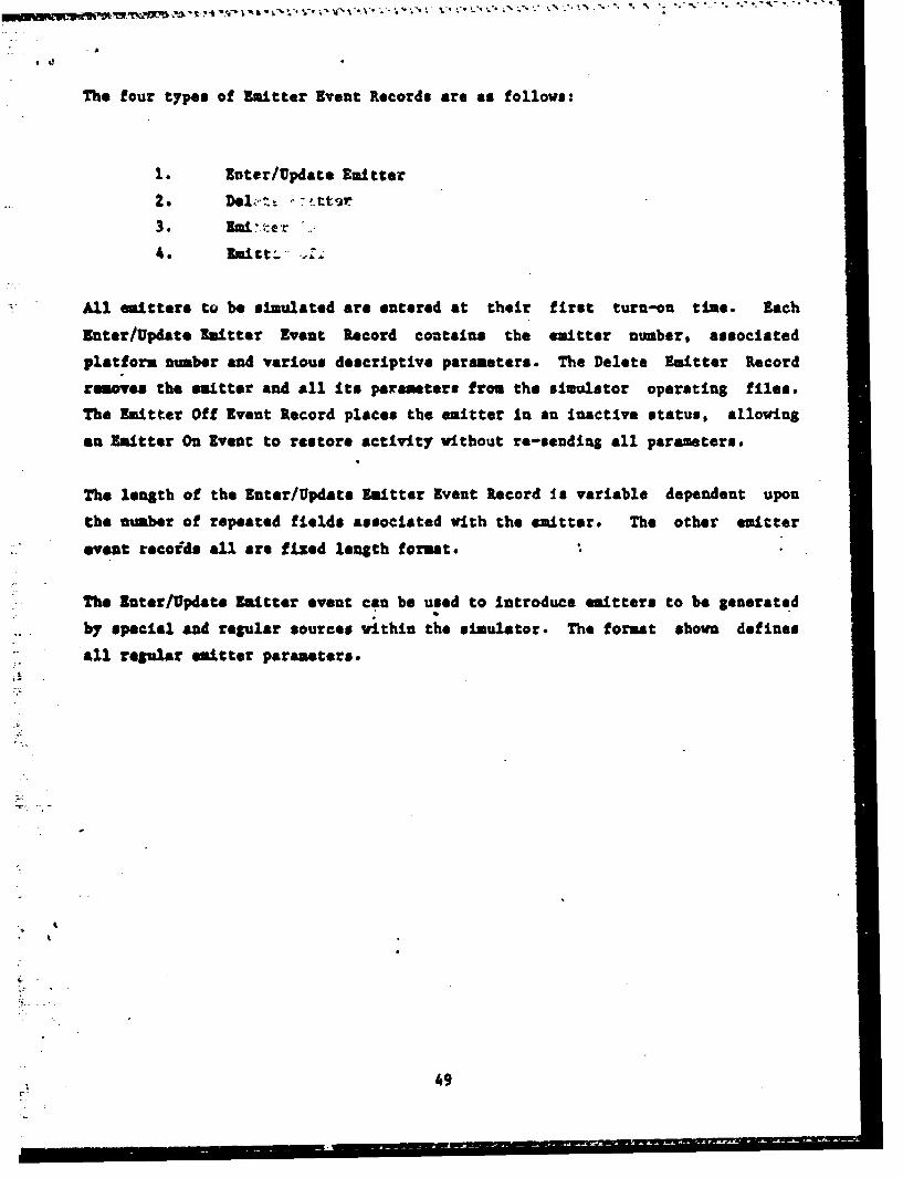
The four types of Emitter Event Records are as follows:
1. Enter/Update Emitter
2. Del;, t - ,.tt~ar
3. m:e'r e .
All emitters to be simulated are entered at their first turn-on time. Each
inter/Update Emitter Event Record contains the emitter number, associated
platform number and various descriptive parameters. The Delete Emitter Record
removes the emitter and all its parameters from the simulator operating file@.
The Emitter Off Event Record places the emitter in an inactive status, allowing
an Emitter On Event to restore activity without re-sending all parameters.
The length of the Enter/Update Emitter Event Record Is variable dependent upon
the number of repeated fields associated with the emitter. The other emitter
event recoids all are fixed length format.
The inter/Update Emitter event can be used to Introduce emitters to be generated
by special and regular sources vithin the simulator. The format shown defines
all regular emitter parameters.
49
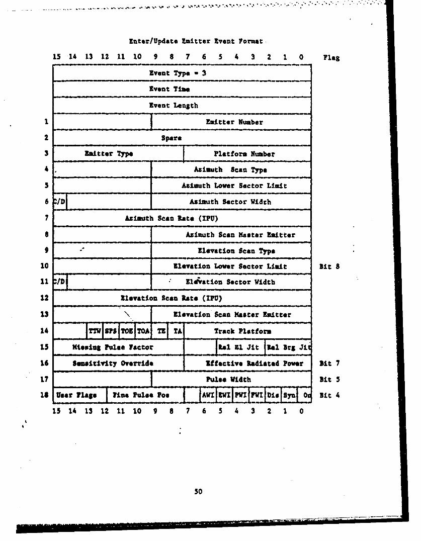
Enter/Update Emitter Event Format.
15 14 13 12 11 10 9 8 7 6 5 4 3 2 1 0 Flag
Event Type - 3
Event Time
Event Length
2 $par*
3 Emte n Platform Number
4 Azimuth Scan Type
5 Atisuth Lover Sector Limit
6 Azimuth Sector Width
7 Azimuth Scan Rate (IPU)
8 Azimuth Scan Master Emitter
9 - Elevation Scan Type
10 Elevation Lover Sector Limit Bit 8
11 10/v ldration Sector Width
12 Elevation Scan Rate (IPU)
13 Elevation Scan Heaster Emitter
141 ITT1EFIOZAII TL : Track Platform
i5 HisOing Pulse Factor 1 A
16 Sensitivity Override Effective Radiated Pover Bit 7
17 Pus Width Bit 5
IS Usear Flags line Pulse Poo AB V Y Y i y it 4
15 14 13 12 It 10 9 8 7 6 5 4 3 2 1 04
4
50
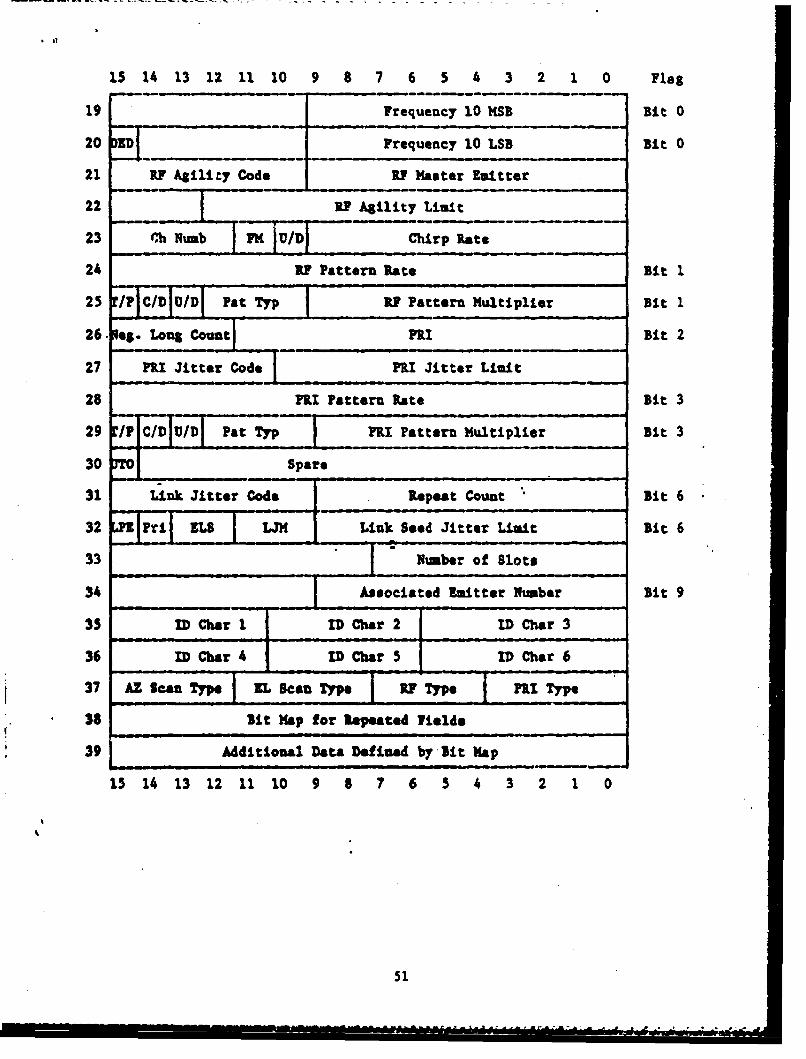
15 14 13 12 11 10 9 8 7 6 5 4 3 2 1 0 Flag
19 Frequency 10 1SB Bit 0
20 .!D. Frequency 10 LSB Bit 0
21 RI Agility Code RY Master Emitter
22 R Agility Limit
23 C~h limb PH 7 _____CirpRat
24 RA Pattern Rate Bit 1
25 F CIDID Pat Typ R7 Pattern Multiplier Bit 1
26 leg. Long Count P1I Bit 2
27 FRI Jitter Code 1RI Jitter Limit
28 FRI Pattern Rate Bit 3
29 /i CIDhKI Pat Typ FRI Pattern Multiplier Bit 3
30 Spare
31 Link Jitter Code Repet Count Bit 6
32 _ri EL LJM Link Seed Jitter Limit Bit 6
33 Nvmber of Slots
34 Associated Emitter Number Bit 9
35 ID Char I ID Char 2 ID Char 3
36 ID Char 4 ID Char 5 ID Char 6
37 AZ Scan Type IL Scan Type IF Type PRI Type
3$ Sit Map for Repeated Yields
39 Additional Data Defined by Bit Map
15 14 13 12 11 10 9 8 7 6 5 4 3 2 1 0
51
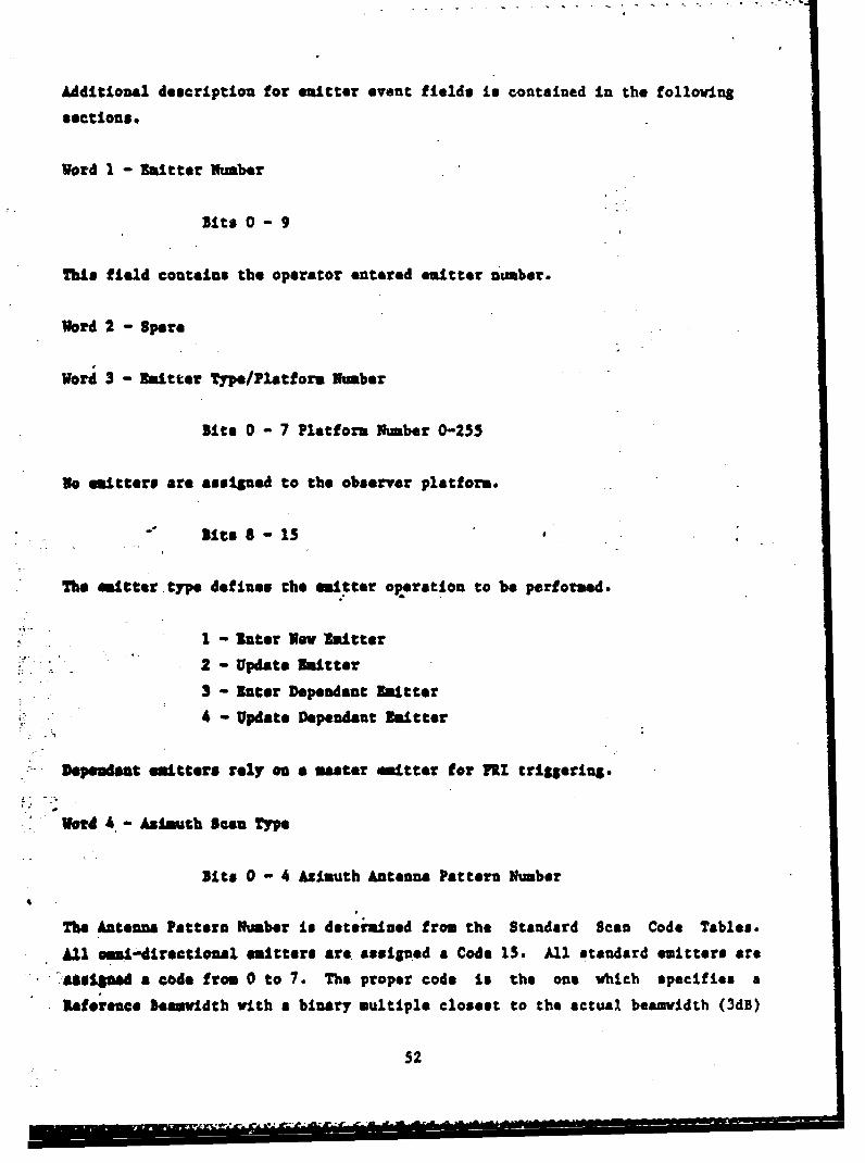
Additional description for emitter event fields is contained in the following
sections.
Word 1 - mitter lumber
Bits 0 - 9
This field contains the operator entered emitter number.
Word 2 - Spare
Word 3 - Emitter Type/Platform limber
Bits 0 - 7 Platform Iumber 0-255
no emitters are assigned to the observer platform.
Bits 8- 15
The Itter type defines the emitter operation to be performed.
-I - riter lowv mitter
2 - Update Xmitter
3 - lnter Dependent hitter
4 - Update Dependent Emitter
Depeudat emitters rely on a master emitter for FRI triggering.
Vord 4 - Asimuth Sua Type
Bits 0 - 4 Azimuth Antenna Pattern Number
The Antenna Pattern Number is determined from the Standard Scan Code Tables.
A11 amni-directional emitters are asssigned a Code 15. All standard emitters are
Susissed a code from 0 to 7. The proper code Is the one which specifies a
leference eamridth with a binary multiple closest to the actual beamvidth (3dB)
52

of the emitter. The reference beauvidths and uultiples are shown in the
Standard Emitter Antenna Scan Table. Special Scan Patterns may be used to
incorporate nonstandard antenna patterns.
Sits 4 - 6 Azimuth Boazmidth Factor
The closest antenna beamvidtb from the Antenna Scan tables designate both the
reference beauwIdth and a multiplier. The code for the Besawidth factor is
derived from the leamwidth Factor Code Table table.
Bit 7 Azimuth Directional Mode
0 - unidirectional
I - bidirectional
Emitters with full circular scan coverage are designated as undirectional.
Bit 8 Aztimuth Blank Flag
The blank flag specifies whether. bidirectional emitters should radiate during
the return pass. A value of zero allows radiation, a value of one inhibits
radiation. For unidirectional or stationary emitters, or conical scanning
emitters, the flag is clear.
Bit 9 External Azimuth Synchronization
0 - Scan period Is continuous
1 - Scan period Is discrete
Externally synced asmiuth scans are reset to the lover sector boundary whenever
the elevation scan sector limit is reached.
Word 5 Azimuth Lower Scan Sector Boundary
Bits 0 - 9
53

Tor sector scanning emitters, a lover boundary and sector width are established
which define the azimuthal lmalts of the antenna mainbesa with respect to the
heading of the carrying platform. The boundaries are measured clockwise from
platform headiug and are expressed in binary angular measurement with the
following least significant bit (LSB) units.
LSB - (Nultiplier) (360 degrees)/4096 increments
The multiplier (1,2,4,...,128) is the value referenced by the esauvidth Factor
(Word 4) as discussed previously.
hitters with full circular scan coverage should have a lower boundary of 512
and an upper boundary of 1024, adjusted by the scan multiplier. Stationary
emitters should have a scan sector width of zero.
Word 6 - Asimuth Sector Width/Discrete Flag
- Sits 0-9 Sector Width
Sector width defines thb size of the sector to be swept for scanning emitters.
-Mw ormat Is Ideutical to that for lower sector limit. For stationary
te41;,as, the ftleh, is set to zero. For circular scanning emitters, the sector
• -. .h is set .to 10Z4, adjusted by the scan multiplier.
-it 15 Discrete Flag
0 - Continuous
1 - Discrete
ftst.aute aeming mitters have their scan periods forced to be a multiple of
.%be asitters FMI. When the sector limit is reached, the current position is
reset to zero and the overflow is lost. For continuous emitters, the overflow
Is retained.
Vord 7 - Scan Rats Index
54
-. - I I U I

Bits 0 - 15 Increments Per Microsecond (IPU)
The IPU field describes the rate at Vhich scanning emitters move through their
scan pattern. The value is the number of increments to move through the pattern
for each pulse output. The value is an unsigned 16 bit number, with an LSB of
1/65536 IPU. The folloving algorithm is used to derive the field value.
IPU - (Sector Width) (Direction Code + 1)*(4096/360)*(65536) / (SRI * KUL)
where: SRI Is scan rate interval (in USEC)
Multiplier is a function of beari.dthDirection Code is 0 for unidirectional, 1 for bidirectional
Word 8 - Azimuth Scan Master Emitter
For emitters with scan rates dependant on other emitters, this field contains
the operator emitter number of the emitter to provide scan rate control.
Word 9 - Elevation Scan Type
Bits 0 - 4 Elevation Aqtenna Pattern Number
The Antenna Pattern Number is determined from the Standard Scan Code Tables.
All omni-directional emitters are assigned a Code 15. All standard emitters are
assigned a code from 0 to 7. The proper code is the one which specifies a
Reference Bemrvidth with a binary multiple closest to the actual beamvidth (3dB)
of the emitter. The reference beamvidths and multiples are shown in the
Standard Emitter Antenna Scan Table. Special Scan Patterns may be used to
incorporate nonstandard antenna patterns.
Bits 4 - 6 Elevation Bemvidth Factor
The closest antenna beaavidth from the Antenna Scan tables designate both the
reference beemvidth and a multiplier. The code for the Beamwidth factor is
derived from the Nesawidth Factor Code Table table.
Bit 7 Elevation Directional Mode
55

0 - unidirectional
I - bidirectional
-fmitters with full circular scan coverage are designated as undirectional.
Slit 8 Elevation Blank Flag
The blank flag specifies whether bidirectional emitters should radiate during
the return pass. A value of zero allows radiation, a value of one inhibits
radiation. For unidirectional or stationary emitters, or conical scanning
emitters, the flag Is clear.
Bit 9 External Elevation Synchronization
0 - Scan period is continuous
1 - Scan period Is discrete
.Externally synced Elevation scans are reset to the lower sector boundary
whenever the azimuth scan sector limit Is reached.
Vorod 10 Elevation Lover Scan Sector Boundary
,its 0 - 9
lot sector scanning emitters, a lower boundary and sector width a&e established
•sk.h daf•te the Elevation limits of the antenna mainbeam with respect to the
headig of the carrying platform. The boundaries are measured clockwise from
plattfom heading and are expressed in binary angular measurement with the
following least significant bit (LSB) units.
LSk 1 (Multiplier) (360 degrens)/4096 increments
The sultiplier (1,2,4,...,128) is the value referenced by the Beanvidth Factor
(Word 4) as discussed previously.
56
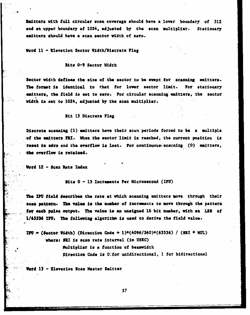
fmitters with full circular scan coverage should have a lover boundary of 512
and an upper boundary of 1024. adjusted by the scan multiplier. Stationary
emitters should have a scan sector width of zero.
Word 11 - Elevation Sector Wldth/Dlscrete Flag
lit* 0-9 Sector Width
Seqtor width defines the size of the sector to be svept for scanning emitters.
The format is Identical to that for lover sector limit. For stationary
emitters, the field is set to zero. For circular scanning emitters, the sector
vidth Is set to 1024. adjusted by the scan multiplier.
Bit 15 Discrete Flag
Discrete scmning (1) emitters have their scan periods forced to be a multiple
of the emitters nI. When the sector linit is reached, the current position is
reset to a8roe snd the overflov is lost. For continuous, scaning (0) emitters,
, tbe overflow is retained.
Word 12 - Scan late Index
Bit@ 0 - 15 Increments Per Microsecond (IF)
The M field describes the rate at which scaniang emitters move through their
scan pattern. The value Is the number of increments to move through the pattern
for eaeh p•Lse output. The value is an unsigned 16 bit number, with an LS. of
1/65536 IU. The followinS algorithm is used to derive the field value.
VU.- (Sctor Width) (Direction Code + 1)*(4096/360)*(65536) / (SRI * MUL)
whereh SRI Is scan rate Interval (in USEC)
)Hultiplier Is a function of beasmvidth
Direction Code is O:for unidirectional, I for bidirectional
Word 13 - Elevation Scan Master Emitter
57

Pot emitters with scan rates dependent on other emitters, this field contains
the operat6r emitter number of the emitter to provide scan rate control.
Word 14 - Track Platform/Track Flags/Video Flags
Bits 0-7 Track Platform
'Thi. field contains the platform number vhih the emitter will automatically
treck in realtime. For non-tracking emitters, this Is set to the platform
wmber to whlch the emitter is linked. As the emitter is entered in realtime,
the platform number is checked to see !etber the emitter Is tracking the XV
"system, based on the ZW system platform number for the current simulation. Once
per simulated second, a new scan lower limit is computed and output for each
tracking emitter.
lit 8 TA
ýq :• Mt A4-ai4fies that the track platform is to be tracked in Azimuth.
Sit 9 TI
Uis bit signifies that the track platform is to be tracked in elevation.
Bit 10 TOA
) -hMs bit soigiU that the observer platform is to be tracked In azimuth.
sit 11 Tog
This bit isnifies that the observer platform is to be tracked in elevation.
lit 12 BPS
This bit signifies that the emitter is to trigger the SPS video channel. SPS
.p.l. s width and offset are stored as additional fields.
58

Bit 13 TTVS
This bit signifies that the emitter is to trigger the TTWS video channel. TNWS
pulse width and offset are stored as additional fields.
Word Missing Pulse Factor/lal El Jitter/Rel Brg Jitter
Uits 0 - 2 Relative Bearing Jitter
This field Is used to designate the amount of random pulse-to-pulse variation in
the relative bearing of an emitter. The code is a function of the limit of
relative bearing Jitter, assuming a uniform double sided distribution around the
true bearing. The relative bearing Jitter limit in BAMS should be used to
derive the code by locating the closest value in the Random Number Code Table.
Bits 3 - 6 Relative Elevation Jitter
This field: is used to designate the mount of random pulse-to-pulse variation, in
the relative elevation of an emitter. The code is a function of the limit of
relative elevation Jitter, assuingl a Wiifor. double sided distribution around
the true elevation. The relative elevation Jitter limit in AMBS should be used
to derive the code by locating the closest value In the Random Number Code
Teble.
Bits 8 - 15 Missing Pulse Factor
Tits field oostains a uissing pulse factor which Is used to randomly drop a
peoestaps of the pulses which would normally be generated for an emitter. The
va49 represents the percent of pulses to be Intentionally dropped, where the
~ loost lp1"ificant bit equals .390625 percent.
2 Word Sensitivity Overrida/Effective Radiated Pover
Bits 8 - 15 Sensitivity Override
This field contains an optional sensitivity value which is used to inhibit
59
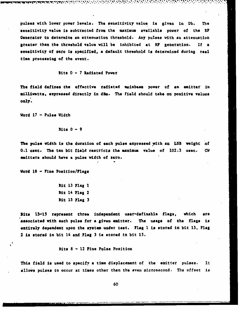
pulses with lover power levels. The sensitivity value is given in Db. The
sensitivity value is subtracted from the maximum available power of the RP
Generator to determine an attenuation threshold. Any pulses with an attenuation
greater than the threshold value will be inhibited at R? generation. If a
sensitivity of zero is specified, a default threshold is determined during real
time processing of the event.
Bits 0 - 7 Radiated Power
The field defines the effective radiated nainbe*a power of an emitter in
milliwatts, expressed directly in dBm. The field should take on positive values
only.
Word 17 - Pulse Width
Bits 0 - 9
The pulse width is the duration of each pulse expressed with an LSB weight of
0.1 usec. The ten bit field restricts the maximum value of 102.3 usec. CW
emitters should have a pulse width of zero.
Word 18 - Fine Position/Flags
Bit 13 Flag 1
Bit 14 Flag 2
Bit 15 Flag 3
Site 13-15 represent three independent user-definable flags, which are
associated with each pulse for a given emitter. The usase of the flags is
entirely dependent upon the system under test. Flag 1 is stored in bit 13, Flag
2 Is stored in bit 14 and Flag 3 is stored In bit 15.
Bits 8 - 12 Fine Pulse Position
This field is used to specify a time displacement of the emitter pulses. It
allows pulses to occur at times other than the even microsecond. The offset is
60

-4---~flr4k.. I -'kk~x 0, Ljw -% IN 'A % ''
measured In Increments of 50 nanoseconds.
Bit 6 - Azimuth Scan Write Inhibit
Bit 5 - Elevation Scan Write Inhibit
Bit 4 - Pri Modulation Write Inhibit
Bit 3 - Frequency Modulation Write Inhibit
Bits 3-6 represent flags used to inhibit updating dynamic position for scan and
periodic modulations. Emitters with these flags set will not advance the
current scan or modulation pattern position for the master emitter. All
associated scan and frequency signals, and dependent emitters use these flags to
inbibit interference with period generation.
Bit 2 - PRI Display
This flag is used to enable output of the PRI display for an emitter. When the
flag is set, the pulse train may be ovserved at the video output of the Digital
Generator. -
Bit 1 - Scan Sync
This flag is used to enable generation of the scan period trigger. When the
flag is set, a transition ts generated for the AZ and EL sync outputs whenever
the emitter reaches a scan sector limit. Scan sync is automatically removed
from the previously selected emitter when a new emitter is specified.
Bit 0 - On
The On flag determines whether an enitter will generate pulses. Emitters may be
entered in a non radiating state, and later turned on by an Emitter On event.
Word 19 - Frequency MSB
Bits 0 - 9
This field contains the ten most sign'ficant bits of frequency.
61

..- -.-- .w-*r ~� bt C *' d*1-• "•-% •1." ILI' ".'.. * '." - m * -'5
Word 20 - Frequency LSB/Dedicated Flag
Bits 0 - 9 Frequency LSB
This field contains the ten least significant bits of frequency. The field has
a least significant bit of .125 $fhz. When com'ained with word 19, a twenty bit
frequency word is crested.
Bit 15 Dedicated Flag
For emitters vith direct assign R3 channels, this flag specifies that the
emitter is to have dedicated usage of the channel.. As the emitter is entered in
realtime, the assigned channel is removed from the pool. The channel is
returned to the pool when the emitter is deleted.
Word 21 - RF Master Emitter/RF Agility Code
Axts 11-16 RB Agility Code
This field Is used to designate the maximum number of bits of frequency to
incorporate random pulse-to-pulse frequency aility. The code Is a function of
the frequency deviation limit, assuming a uniform double-sided distribution
around the bass frequency. The frequency deviation should be translated to
units of .125 )hs and the code derived from the Random Number Code Table. The
code for the smallest table value which meets or exceeds the desired frequency
deviation should be selected.
Bits 0 - 9 a1 Master aLitter
for emitters with associated frequency modulation, this field specified the
operator emitter number of the master emitter. The periodic modulation will
depend upon the master emitter for. its timing.
Word 22 - RY Agility Limit
62
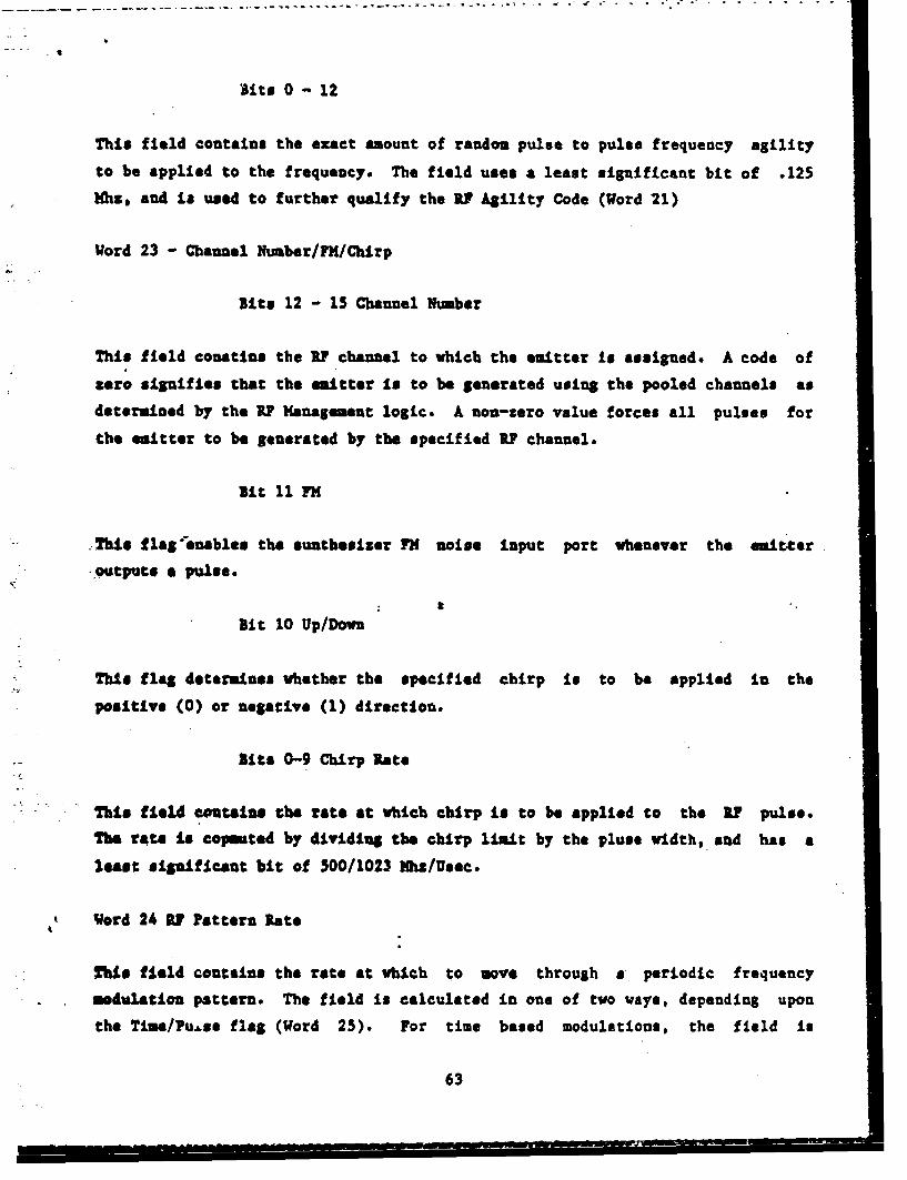
Aits 0 - 12
This field contains the exact amount of random pulse to pulse frequency agility
to be applied to the frequency. The field uses a least significant bit of .125
ihz, and is used to further qualify the RY Agility Code (Word 21)
Word 23 - Channel NLuber/FM/Chirp
Bits 12 - 15 Channel Number
This field conatins the R? channel to which the emitter Is assigned. A code of
zero signifies that the emitter is to be generated using the pooled channels as
determined by the RY Management logic. A non-zero value forces all pulses for
the emitter to be generated by the specified R? channel.
slit 11 7M
This flaS-enables the sunthesiser FM noise Input port whenever the emitter
outputs a pulse.
Bit 10 Up/Down
This flag determines whether the specified chirp Is to be applied in the
positive (0) or negative (1) direction.
Bits 0-9 Chirp Rate
This field contains the rate at which chirp is to be applied to the RF pulse.
The rate is copeuted by dividiug the chirp limit by the pluse width, sad has a
least significant bit of 500/1023 )hu/Usec.
Vord 24 RY Pattern Rate
This field contains the rate at which to move through a periodic frequency
modulation pattern. The field is calculated in one of two ways, depending upon
the Tine/Puse flag (Word 25). For time based modulations, the field is
63

referred to as IPU, hos a least significant bit of 1/65536 increments/usec, and
is calculated as follows.
IPU - (1024) * (65536) / (Period)
Where Period is. i.n Usec
For pulse based modulations, the field is referred to as IPP, has a least
significsut bit of 1/256 increments/pulse, and is calculated as follows.
IPP (1024) * (256) / (Period)
'Where Period is in Usee
Word 25 M Kodulation Flags/Pattern Multiplier
Bit 15 Time/Pulse
The Time/Pulse flag determines whether the periodic modulation is updated based
on the number of pulses output, or the elapsed time. For time based (0)
-liodulationa, the U'U field is multiplied by the current PRI for each pulse. to
detersLue the amount to advance through the modulation pattern. For pulse based
(1) modulations, the ZIPP fieild is *used directly to advance through the
modulation pattern.
Bit 14 Discrete Flag
Discrete modulation (1) suitters have their modulation periods forced to be a
, lelple of the emitters li. When the pattern limit is reached, the current
position is reset to zero and the overflow is lost. For continuous modulation
(0) msitters, the overflow Is retained.
Sit 13 Up/Down
The Up/Down flag controls which direction the modulation moves through the
pattern. For Up (0), the pattern begins at position zero, and advances to the
upper limit. For Down (1), the pattern begins at the upper limit, and advances
go position zero. This allows the Digital Generator to generate inverse
modulation patterns using the same pattern type.
64

Bits 10 - 12 Pattern Type
This field selects the pattern type to be applied to a periodic modulation.
Patterns are selected from the following types.
Code Pattern Type
0 Ramp
1 Concave Increasing Exponential (0At)
2 Convex Increasing Exponential (1-eAt )
3 Unassigned
4 Unassigned
5 Unassigned
6 Trapezoidal
7 Sinusoidal
Bits 0 - 9 R1 Pattern Multiplier
This field determines the amplitude of the periodic modulation. This represents
the saxinum excursion frou the base value. The field has a least significant
bit of 255/256 Hhz. For sinusoudal pattern types, the base value is set to the
lover limit of the sine wave, and the uodulation amplitude is set to twice the
stnausoidal excursion.
Word 26 - Long Count/FIR
Bits 12 - 15
For amitters with FRI values exceeding 4095, two Digital Generator slots are
allo*"ted. This field specifies the number of times to repeat the dummy FRI
value to generate the desired effective PRI. The value is stored as a negative
number.
Bits 0 - 11 PRI
This field contains the base PRI for the emitter, vith a least siguif-cant bit
65
S. . . . _ _ • . . . " • -• L L • •s` *- = .~ ,s-A -a • -- • -t . . ` -¶ L
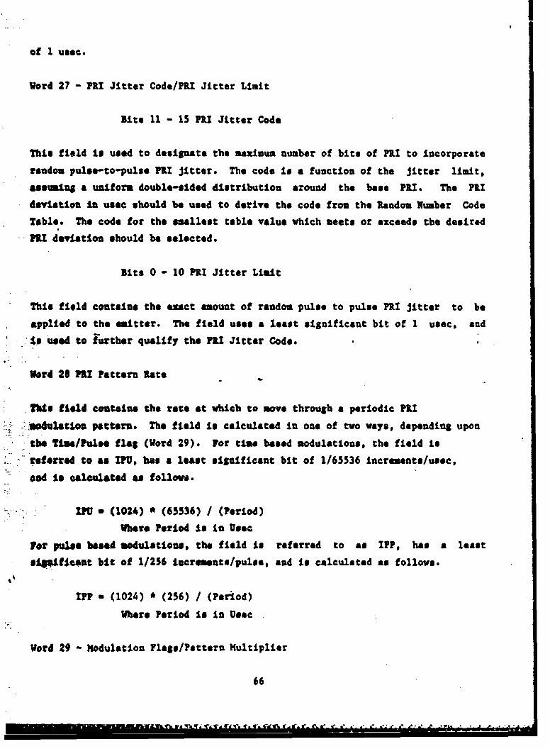
of I usec.
Word 27 - PR$ Jitter Code/?RI Jitter Liait
Bits 11 - 15 P3,1 Jitter Code
This field is used to designate the maximum number of bits of PRI to incorporate
random pulse-to-pulse PIt Jitter. The code is a function of the Jitter limit,
assusnlg a uniform double-sided distribution around the base PRI. The PR!
deviation in usec should be used to derive the code from the Random Number Code
Table. The code for the smallest table value which meets or exceeds the desired
P&I deviation should be selected.
Bits 0 - 10 P1I Jitter Limit
This field contains the exact amount of random pulse to pulse PRI Jitter to be
applied to the emitter. The field uses a least significaut bit of 1 usec, and
I s used to further qualify the PRI Jitter Code.
Word 28 PRI Pattern Rate
T.?Us field costains the rate at which to move through a periodic P71
. *sdu8atloo pattern. The field is calculated in one of two vays, depending upon
the Tims/Pul"e flat (Word 29). For time based modulations, the field is
referred to as IU, has a least significant bit of 1/65536 Lncrements/usec,
and to calclated as folles.
- .FU a (1024) * (65536) I (Period)
Where Period is in Usec
for pulase based modulations, the field Is referred to as IPP, has a least
sip.ficant bit of 1/256 increments/pulse, and is calculated as follows.
IPP a (1024) * (256) / (Period)
Where Period is in Usec
Word 29 - Modulation Flags/Pattern Multiplier
66

lit 15 Time/Pulse
The Time/Pulse flag determines whether the periodic modulation is updated based
on the number of pulses output, or the elapsed time. For time based (0)
modulations, the IPU field is multiplied by the current PRI for each pulse to
determine the amount to advance through the modulation pattern. For pulse based
(1) modulations, the IPP field is used directly to advance through the
modulation pattern.
Bit 14 Discrete Flag
Discrete modulation (1) emitters have their modulation periods forced to be a
multiple of the emitters IRI. When the pattern limit is reached, the current
position is reset to tero and the overflov Is lost. For continuous modulation
(0) emitters, the overflow is retained.
Bit 13 Up/Domn
The Up/Down flag controls which. direction the modulation moves through the
pattern. For Up (0), the pattern begins at position zero, and advances to the
upper limit. For Down (1), the pattern begins at the upper limit, and advances
to position tero. This allows the Digital Generator to generate inverse
modulation patterns using the same pattern type.
Bits 10 - 12 Pattern Type
This field selects the pattern type to be applied to a periodic modulation.
Patterns are selected from the following types.
Code Pattern Type
0 &&up
1 Concave Increasing:txponential (e At)
At2 Convex Increasing Exponential (1-e )
3 Unassigned
Unassigned
67
d~~~~~ ~ ~ ~ ~ N I-- -r A#~- ~ SiisM---

5 Unassigned
6 Trapezoidal
7 Sinusoidal
Blit 0 - 9 PRI Pattern Multiplier
This field determines the amplitude of the periodic modulation. This represents
the maximum excursion from the base value. The field has a least significant
bit of 255/256 use@. For sinusoudal pattern types, the base value is set to the
lover limit of the sine wave, and the modulation amplitude is set to twice the
sinusoidal excursion.
Word 30 - Turn Off
lit fifteen of word thirty is a flag which identifies an emitter which must be
turned off in order tv perform a mode change. Certain emitters, notably those
using sync emitters to generate short PRI's and those using Link Code Jitter,
.- sat be turned off in order to perform an emitter update without creating
'dropped mitters.
Word 31 - Link Jitter Code/Rpeast Count
Bits 10 - 15 Link Jitter Code
This field is used to designate the maximum number of bits of Link Seed/Jitter
to incorporate random pulse-to-pulse Jitter. The code is a function of the
Jitter limit, assuming a uniform positive only distribution around the base
- v aleo The deviation should be used to derive the code from the Random Number
Code Table. The code for the smallest table value which meets or exceeds the
desired deviation should be selected.
Bits 0 - 9 Repeat Count
"This field contains the number of pulses to output before using the Pattern
Ovtch Link emitter number. The number of pulses is derived from the desired
dwell time and the FRI of the emitter.
68

4
Word 32 - Emitter Link Select/Link Jitter Mode/Link Seed Jitter Limit
Bit 15 Link Previous Emitter
This flag signifies that the normal link for this slot is to be the previous
slot. For emitters with desired repeat counts exceeding the capability of the
Digital Generator, two slots are allocated, with the second slot having a normal
sequence link of the previous slot. The resulting repeat count is the product
of the repeat counts of the two slots.
Bit 14 Priority
This field contains a priority flag for use by the Digital Generator in
resolving emitter conflicts for pulse requests. An emitter with priority will
bump other emitters from their desired time slots when more than four
siaulatenous pulses are attempted to be generated digitally. In addition,
priority eitters will have first access to available- RF channles when the
pulses for a given microsecond are allocated to the available resources.
Bits 12 - 13 Emitter Link Select
This field controls the emitter linking method to be used, defined as follows.
0 - Add link code Jitter to sequence link
1 - Use switch link on PRI pattern overflow
2 a Use switch link on RY pattern overflow
3 - Use switch link on repeat count underflov
Bits 10 - 11 Link Jitter Mode
This field controls the application of Link Seed Jitter, defined as follows.
0 - Link code Jitter
1 - Repeat count Jitter
2 - Seed FRI Jitter random number
69

3 - Seed frequency agility random number
Bits 0 - 9 Link Seed Jitter Limit
This field specifies the amount of Link Seed Jitter to be generated. It is used
to further qualify the Link Seed Jitter Code.
-5Word 33 - Number of Slots
Complex emitters require more than a single Digital Generator slot. This field
specifies the number of slots required. When more than one slot ts used, words
1 through 34 are used to format the parameters for the first slot. The bitmap
in word 38 then specifies which fields are repeated for each additional slot.
A.1 other parameters remain the same for all slots.
Word 34 - Associated Emitter Number
ITnis field contains the operator emitter number of an emitter to be generated8as
a dependaut emitter. The specified emitter is included as a sync emitter for
the emittr currently being enteqred.
S Vqrds 35/36 - Emitter ID
This field contains en emitter identification. The ID is stored as up to six
ASCII characters,, packed In Radix 50 notation as defined by Digital Equipment
Corporation.
,ord 37 - 5ignlp Types
sits 12 1 15 Azimuth Scan Type
4L This field defines the azimuth scan type as follows.
+: . •Code Type
1 Circular
70

2 Sector
3 Raster
A Conical
5 Helical
6 Steady
7 OMNI
a Associated
Sits 8 - 11 Elevation Scan Type
This field defines the elevation scan type as follows.
Code s
I Sector
2 Steady3 01t11
,A Associated
Bits 4 - 7 R1 Sgnal Type
Ths: .field defines the frequency signal type as follows.
S... .Code )3
Continuous WaveS.2 Single Frequency
-- 3 Sequence. Periodic Modulation
S Switching
6 Discrete Agility
7 Multibeam
8 Associated"
Bits 4 - 7 R1 Signal Type
This field defines the FiU signal type as follows.
71
SL. . • -,. m~

t
Code _
I Single PRI
2 Stagger, Pulse Group, Sequence
3 Periodic Modulation
4 Switching
5 Discrete Jitter
Word 38 - litmap
Word thirty eight defines the fields which are repeated for emitters requiring
additional Digital Cenerator slots. Where uultiple bits are set, fields are
repeated in order of increasing bit number. For example, if bits 0 and 1 are
both set, fields repeated for bit 0 are stored before fields repeated for bit 1.
Couplete sets of repeated data are stored, with each set fully defining the next
Digital Generator slot. Repeated fields follow exactly the same format as
corresponding fields vtoren in che base event. Sit. values are defined. asfellerw..
Bit 0 - Frequency list (Words 19/20)
Bit I - Frequency modulation list Words (24/25)
Bit 2 - PU list (Word 26)
Bit 3 - P&U modulation list.(Words 28/29)
bit 4 - Fine position list (Word 18)
lit 5 - Pulse width list (Word 17)
lit 6 - Repeat count list (Words 31/32)
Bit 7 - U? list (Word 16)
Blit 8 - Ilevation start angle list (Word 10)
Bit 9 -Associated emitter list (W,,rd 34)
72
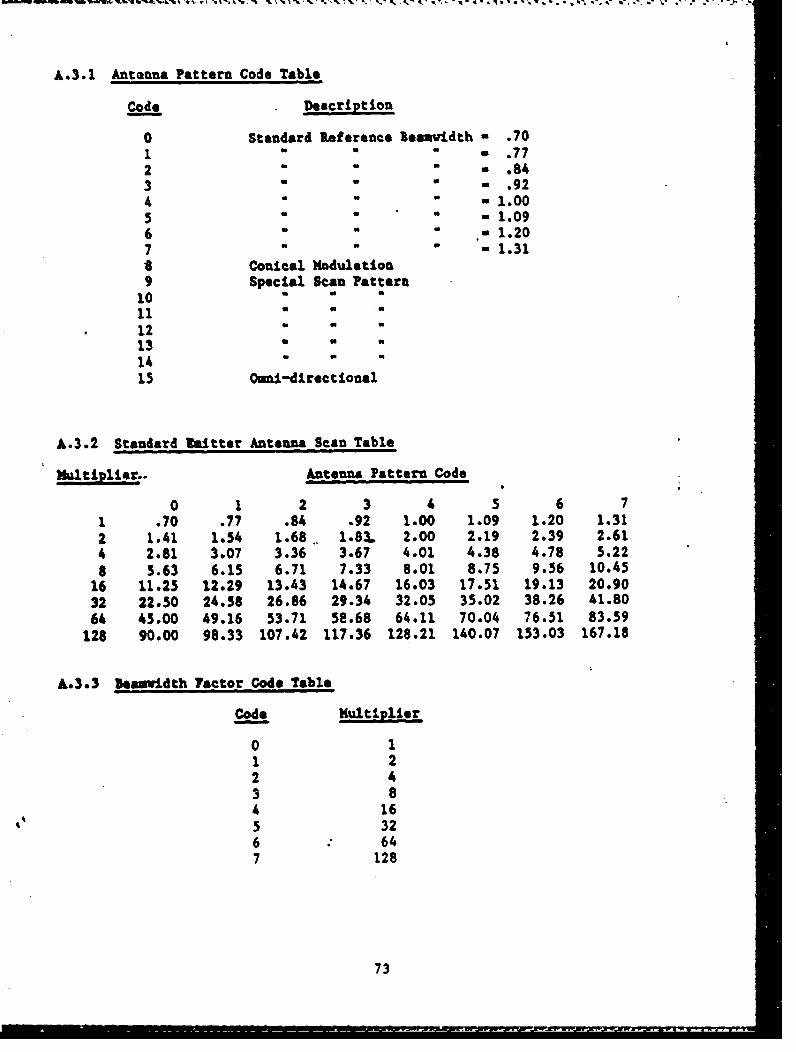
A.3.1 Antenna Pattern Code Table
Code Description
0 Standard Reference leanvidth - .70"1 " .772 " .84"3 a .924 - -1.00" " " 1.096 a a 1.20"7 -1.318 Conical Modulation9 Special Scan Pattern
10 a11 a a
12 "13 a14 "15 Omni-directional
A.3.2 Standard lfitter Antenna Scan Table
Multiplier.. Antenna Pattern Code
0 1 2 3 45 6 7I .70 .77 .84 .92 1.00 1.09 1.20 1.312 1.41 1.54 1.68 1.83. 2.00 2.19 2.39 2.614 2.81 3.07 3.36 3.67 4.01 4.38 4.78 5.228 5.63 6.15 6.71 7.33 8.01 8.75 9.56 10.45
16 11.25 12.29 13.43 14.67 16.03 17.51 19.13 20.9032 22.50 24.58 26.86 29.34 32.05 35.02 38.26 41.8064 45.00 49.16 53.71 58.68 64.11 70.04 76.51 83.59
128 90.00 98.33 107.42 117.36 128.21 140.07 153.03 167.18
A.3.3 _eauvidth Factor Code Table
Code Multiplier
0 11 22 43 84 165 326 647 128
73

A.3.4 Rando. Number Code Table
Cod* Maximum Random Number
0 01 12 33 74 155 316 637 1278 2559 511
10 102311 204712 409513 8191
74

A.4 Delete Emitter
15 14 13 12 11 10 9 8 7 6 5 4 3 2 1 0
EVENT TYPE " 4
TIME IN SECONDS
EMITTER NUMBER
15 14 13 12 11 10 9 8 7 6 5 4 3 2 1 0
A.5 Emitter Off
15 14 13 12 11 10 9 8 7 6 5 4 3 2 1 0
EVENT TYPE a 5
TINE IN SECONDS
EMITTER NUMBER
15 14 13 12 11 10 9 8 7 6 5 4 3 2 1 0
A.6 Emitter On
15 14 13 12 11 10 9 8 7 6 5 4 3 2 1 0
EVENT TYPE -6
TIME IN SECONDS
EMITTER NUMBER
15 14 13 12 11 10 9 8 7 6 5 4 3 2 1 0
"75
APPENDIX B
V •DATA EXTRACTION FILE DESCRIPTION
The Data Extraction file is made up of a series of variable length records each
describing a single scenario event, operator command or status event. Data is
recorded in the order of command or event execution. The records are packed
into 256 word blocks, which are written sequentially to a FILES-1l format file
in 256 word records. Ivents or co ands are allowed to cross block boundaries
when necessary. Any extra words in the last block are filled with zeroes when
the Data Extraction File is closed. Data analysis files are read and processed
offlina as required for performance evaluation.
The Data Extraction file contains all scenario events, operator commands, and
status data pertinent to a simulation run. The first field of each record
the event or comnand code, as described below. The second field of each record
is the actual execution time in clock ticks, defined in"the DX header.
The third field of each record contains the simulated time in seconds at which
the event occurred. The fourth field contains the total number of words in the
record.
The first block (256 words) of the DX file contains the file header. The header
contains the following data.
76

WORD CONTENTS
1 Tick size > 0 milliseconds/tick< 0 ticks/second
2 File Type - 700 + Revision Level43 Simulation Run Date44 Simulation Run Time (minutes)
45-51 Scenario File lame52-58 Maximum Power File Nsae59-65 Receiver Gain File Nsame66-72 Sensitivity File Name
73 EW System Platform Number74 Test Mode
0 - Fixed Antenna/Digital Output1 - Rotating Antenna/DLSLtal Output2 --Fixed Antenna/iF Output3 - Rotating Antenna/RF Output
158-164 Azimuth Receiver Pattern Code File Name237-243 Elevation Receiver Pattern Code File Name
All fields not described are reserved for use by future programs. All ASCII
fields are stored with the first character in the high byte and the second inthe low byte.
--.)ate is packed as follows:
15 10 9 6 5 0
ILL
77

CODE EVENT OR COMMAND
1 Enter/Update Platform
2 Delete Platform
3 Enter/Update Emitter
4 Delete Emitter
5 Emitter Off
6 Emitter On
30 Dropped Emitter
31 Pulse Count Request Time
32 Record Pulse Counts
33 Record Platform Update Information
34 Record Scan Update Information
64 Start Scenario
65. Stop Scenario
66 Change Acenaria Speed
67 Radiation Off
6$ Radiation On
69 Advance Scenario
70 Uckip Scenario
71 Disable All DX Recording
72 End Si-ultaion Run
-s5 Nausim Power File
96 Receiver Gain File
97 Receiver sensitivity File
98 Azimuth Receiver Pattern File
99 Elevation Receiver Pattern File
78

B.1 Codes 1-6
Event codes one through six correspond to the six event types specified in thescenario file. The parameters for these events, words 2 - N from the scenarioare copied to the DX file following the length parameter as described above.Data for operator events are stored in the same fashion, except that the eventnumber is negated to signify an operator event.
B.2 Code 30 - Dropped Emitter
WORD
0 EVENT TYPE - 30
1
TICK COUNT2
3 SIMULATED TIME
4 RECORD LENGTH , 7
5 EMITTER NUMBER
6 DIGITAL GENERATOR SLOT NUMBER
* The Sign bit of word 5 reflects the status of the Emitter on flag in the
Emitter File at the time the emitter was dropped.
5.3 Code 31 - Pulse Count Request Time Event
WORD
0 EVENT TYPE - 31
1TICK COUNT
2
3 SIMULATED TIME
4 RECORD LENGT- 7
5REQUEST TIME
6
79

1.4 Code 32 - Pulse Counts
WORD
0 EVENT TYPE - 32
TICK COUNT2
3 SIMULATED TIME
4 RECORD LENGTH
5 FIRST OPERATOR EMITTER NUMBER
6 TOTAL PULSES OUTPUT
7 TOTAL AMPLITUDE INHIBITED
8 TOTAL RU DROPPED
9 NEXT OPERATOR EMITTER NUMBER
10 TOTAL PULSES OUTPUT
11 TOTAL AMPLITUDE INHIBITED
12 TOTAL RU DROPPED
Pulse counts for up to 64 emitters are packed in a single pulse count event.If more emitters are to be recorded, additional events are output.
so

3.5 Code 33 - Record Platform Update
WORD
0 EVENT TYPE - 33
1
TICK COUNT2
3 SIMULATED TIME
4 RECORD LENGTH
5 RANGE ATTENUATION 1 ST PLATFORM f
6 REL BEARING PROM EW SYSTEM
7 EEL ELEVATION FROM !W SYSTEM
8 RAGEATENATION [ 2ND PLATFORM
9 REL BEARING FROM 3W SYSTEM
10 REL ELEVATION FROM 3W SYSTEM
N+1 zL BEARING FROM LW SYSTEM
N+2 UEL ELEVATION FROM EW SYSTEM
81

• • : :e.r;• ::•:•..•: . '- - - - - - - -4:-.-• . , : _ ." • : , - -) . •-. I--. . , •. ,•'.. ,' . ;
3.6 Code 34 - Record Scan Update
WORD
0 EVENT TYPE 34
1
TICK COUNT2
3 SINULATED TINE
4 RECORD LENGTH
5 leta EMITTER NUMBER
6 LOWER SECTOR BOUNDARY
7 2nd EMITTER NUMBER
8 LOWER SECTOR BOUNDARY
9 3rd EMITTER NUMBER
10 LOWER SECTOR BOUNDARY
11 4th EMITTER NUMBER
12 LOWER SECTOR BOUNDARY
13 Sth MaTT NUMBER
14 LOWER SECTOR BOUNDARY
N Nth EMITTER NUMBER
N+1 LOWER SECTOR BOUNDARY
Lover Sector Boundary to in units of 360/1024 degrees.Blit 15 of each sector bpoundary Is set for elevation limit, clear for azinuthlinit.
82
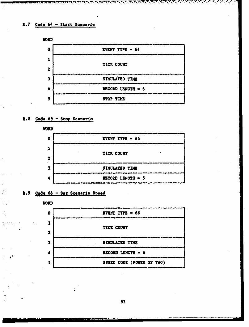
3.7 Code 64 - Start Scenario
WORD
0 EVENT TYPE - 64
TICK COUNT2
3 SIMULATED TIME
4 RECORD LENGTH " 6
5 STOP TIM•
3.8 Code 65 - Stop Scenario
WORD
o EVENT TYPE - 65
TICK COUNT2
3 .01IMULAMCD TIM
46 RECORD LENGTH - 5
1.9 Code 66- gt Scenarlo .Sped
VORD
0 MVY TTYPE 66
TICK COUNT2
3 SIMULTED TIME
4 RECORD LENGTH * 6
5 SPEED CODE (POWER O TWO)
83

1.10 Code 67 - Radiation Off
WORD
0 EVENT TYPE -67
TICK COUNT2
3 SImULaTED TINE
RECORD LENGTH m 5
3.11 Code 68 - Radiation On
WORD
0 EVENT TYPE - 68
TICK COUNT2
-3 SIMULATED TIM.
4 RECORD LENGTH - 5
3.12. Code 69 Advance Scenario
WORD
0 EVENT TYPE - 69
TICK COUNT2
sm 4REC•ORD LIUCTE 6
* ADVANCE TARGET TIME
84

1.13 Code 70 - Backup Scenario
WORD
0 EVENT TYPE - 70
1TICK COUNT
2
3 s 114ULATED, T DO
4 RECORD LEGT a 6
l ~BACKUP TARGET TIME
1.14 Code 71 -Disable All DX Recording
VORD
0 EVENT TYPE- 71
1.15 ~ ~ ~ ~ ~ TC CCOU2NTn Smlain
1
2
S..... 3SIMULATED TIME
4 EUCORD LENGTR - 5
" 3.15 Code 72 &aZd Slaulation Ran
i•0 ZVENT TTY - 72
E TICK COUN
}.•: 3SIMULATED TIME
SREUCORD LENGTH" 5

1.16 Code 95- Maximum Power File
WORD
0 EVETTYPE 95
TICK COUNT2
3 SIMULATED TIME
4 EVENT LIN=TI - 256
5 MAX POWER FIRST FRQUENCY
6 MAX POWER SECOND FREQUENCY
157 MAX POWER LAST FREQUENCY
158 0
255 0
This event is used to record an image of the Maximum Power file used atWatjaliz•tion for the current run. The Max Power file data are copied in order
to words 5 through 158 of the event. The reminder of the event Is zero filledto bave the event occupy one dinc block. The max power values are stored asintager data, with an LSD of 1/128 Db.
86
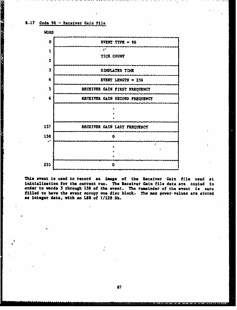
5.17 Code 96 - Receiver Cain File
WORD
0 EVENT TYPE - 96
TICK COUNT2
3 SI4ULATED TIM(
4 EVENT LEN=G? m 256
5 RECEIVER CAIN FIRST FREQUENCY
6 RECEIVER AIN SECOND FREQUENCY
0
157 RECEIVER GAIN LAST FREQUENCY
158 0
S*
255 0
This &vent is used to record an iiage of the Receiver Gain file used atinitialisation for the current run. The Receiver Gain file data are copied inorder to words 5 through 158 of the event. The remainder of the event is zerofilled to have the evou€ occupy one disc block. The max pover, values are storedse integer data, with an L.8 of 1/128 Db.
87

3.18 Code 97 - Receiver Sensitivity File
WORD
0 EVENT TYPE i 97
1TICK COUNT
2
3 SIMULATED TIME
4 EVENT LIN=TE - 256
5 RECEIVER SENSITIVITY FIRST FREQUENCY
6 RECEIVER SENSITIVITY SECOND FREQUENCY
157 RECEIVER SENSITIVITY LAST FREQUENCY
158 0
255 0
This event Is used to record an image of the Receiver Sensitivity file used atinitialization for the current run. The Receiver Sensitivity file data arecopied in order to words 5 through 158 of the event. The remainder of the eventto zero filled to have the event occupy one disc block. The max power valuesare stored as integer data, with an LSB of 1/128 Db.
88
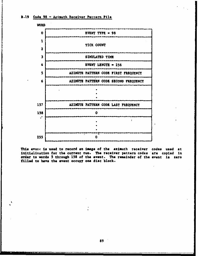
B.19 Code 98 - Aziuuth Receiver Pattern File
WORD
0 EVENT TYPE - 98
1TICK COUNT
2
3 SIMULATED TIME
4 EVENT LENGTH - 256
5 AZIMUTH PATTERR CODE FIRST FRIEQUENCY
6 AZIMUTH PATTERN CODE SECOND FREQUENCY
157 AZIM)UT PATTERN CODE LAST FREQUENCY
158 0
255 0
This evnmr, is used to record an image of the azimuth receiver codes used atinititlisztion for the current run. The receiver pattern codes are copied inorder to words 5 through 158 of the event. The remainder of the event is zerofilled to have the event occupy one disc block.
9

3.20 Code 99 - Elevation Receiver Pattern File
WORD
0 EVENT TYPE a 99
1 TICK COUNT
2
3 SIMULATED TIM
4 EVENT LENGTH - 256
5 ELEVATION PATTERN CODE FIRST FREQUENCY
6 ELEVATION PATTZE!. CODE SECOND FREQUENCY
i0
157 ELEVATION PATTERN CODE LAST FREQUENCY
158 0
255 0
This event Is used to record an imaSe of the elevation receiver codes used atinitialization for the current run. The receiver pattern codes are copied inorder to vords 5 through 158 of the event. The remat.inder of the event is zerofilled to have the event occupy one disc block.
90

APPENDIX C
DIGITAL SUBSYSTEM INTERFACE
The interface between the Digital Generator and the Control Subsystem consists
of three 16 bit paths plus associated status lines. The three paths are Command
-Data, Status Data and Pulse Count Data.
C.1 Command Data
The Command Data path consists of 16 data lines from the Control Subsystem to
the Digital Generator plus a control line. The interface is terminated in the
Control Subsystem by a DR-11M interface card supplied by DEC. The sixteen data
lines of port 3 are used, and a Unibus address of 764020 is selected. The DATA
RLDY OUT 3 signal is asserted whenever new data is loaded into the output
register...All signals are TTL compatible levels.
Commands are output at a maximum rate of one every 12 microseconds. No
acknowledgment is required from.-he Digital Generator.
The data path is divided into two fields: a Command Field in the most
sigificaut six bits and a Value Field in the ten least significant bits. When
all of the Value bits are not used, the field is right justified and the unused
bits are undefined.
When a -mitter mosber Is loaded, all subsequent commands reference this emitter
mti. a nae emitter nunber is loaded. All angles (beainSe and headinSs) are ten
bit fields in units of 360/1024 Degrees, referred to as Binary Angular Measure
(W's), divided by the Scan Multiplier. A list of valid commands and Value
fields follows.
91

COMAD DATA FIELD COMMANDNAME CODE
LFRQJC Load Frequency Agility Limit MSB(3),Frequency Agility Code(4) 40LCRIRP Load Chirp Rate 41LFCHAN Load Frequency Chirp Up/Down(l),External FM Enable(l), 42
RF Channel Code(4)LFIPUL Load Frequency Pattern Rate (IPU) LSB 43LFIPUM Load Frequency Pattern Rate (IPB) MSB 44LFRQTP Load Frequency Pattern Type(3), Up/Down Count(l), 45
Continuous/Discrete(1),Time/Pulse(1)LRQML Load Frequency Pattern Multiplier 46LFRQEK Load Frequency Base Emitter Number 47LPUWID Load Pulse Width 48LF POS Load Fine Pulse Position(5),User Flags(3) 49LATTER Load Base Attenuation 50LTHRSR Load Threshold 51LMPFAC Load Missing Pulse Factor 52
C.1.2 System Commands
COMMAND DATA FIELD COMMANDNAME CODE
LOWNHD Load Observer Reading 33LCLIMS Loid Observer Climb Angle 36LSYCON Load R" BIT DOA Select(3),Rotating Receiver Enable(l), 53
RI Mode Enable(l), RF Enable(l)LRFPOL Load "F Channel Pool Selection 54LRESET Reset Emitter Active Flags(l), Reset Digital/RF Cenerators 55LMIWHR Load Scenario Time BCD Minutes(7),Hours(3) 56LSECND Load Scenario Time BCD Seconds 57RPCNTS Read Emitter Pulse Counts 62
C.2 Status Data
The Status Data path consists of sixteen data lines from the Digital Subsystem
to the Control Subsystem. The sixteen lines are driven by a sixteen bit status
" register which always contains the data selected by the last Read command
received from the ControAl Subsystem. The information Is right justified with
unused bits set to zero. Data is selected by command code 63, and is identical
in format to data in the value fields of the corresponding Load commands (0-62).
Other data formats are described .in Sections C.2.1 and C.2.2.
The Interface is terminated in the Control Subsystem by a DR-1lL interface card
supplied by DEC. The sixteen data lines of port A are used, and a Unibus
address of 764030 is selected. The 16 bit status register is updated by the
93

Digital Subsystem within 12 microseconds of receipt of a Read command. All
levels are TTL compatible.
C.2.1 Dropped Emitter Number
When the Digital Subsystem discovers that it has gone .1 seconds without
generating a pulse for an active emitter, it saves the emitter number to be read
by the Control Subsystem. When the Control Subsystem issues a Read Dropped
Emitter Number Command, the Digital Generator will respond by moving the ten bit
emitter number to the Status Register.
C.3 Pulse Counter
The Digital Generator maintains three sixteen bit counter for each emitter
number. The counters are incremented each time a pulse is generated or dropped.
Upon receipt of an Initiate Transfer of Pulse Counts command (Command 55), the
Digital Generator transfers all of the pulse counters to the Control Subsystem
via the Pulse Counts data path which is a Direct 1emorn Access channel into 'the
main smeory of the Control Subsystem. Each counter is cleared after it is
transferred. The Digital Generator mill prevent any of the counters from
counting past the suaxim number of 65536.
The Direct memory Access channel is implemented by a KITll-D Interface system
supplied by DEC, using a Unibus address of 764000. The DATA AVAILABLE IN signal
is asserted each time a data word is to be transferred. All levels are TTLc€mpatble.
94
-- - - - - - - - - -
APPENDIX D
TIS - AISF NAVICATION HESSAGE
The TWEZS Navigation message ti sent periodically- using a standard RS 232C
serial couuunications line at 9600 baud. Message transmission begins when the
first Start Scenario comand is issued at the TEWrS operator's console. The
AISi coputer shall transmit a one byte request message to the TEWES computer
each time a navigation message is desired. The TMNS shall immediately transmit
the latest navigation data. Transmission continues at the normal rate vhen
freeze mode is entered, with static parameters output for the EW system. Pulse
count data continues to be updated during freeze mode. Data shall be sent as
8-bit binary codes, with no parity bits and one stop bit. Within each data
byte, the LSD of the byte corresponds to the LSB of the specific field. Where
the field dontains less than 8 bits, the field is right Justified within the
transmitted byte. The message shall contain the IIuG-I time cde read as
transfer of the data initiated, followed by the current TE•S scenario time.
This is followed by the current position, heading, latitude, longitude, pitch
and roll angles for the NW system. The scenario speed power of two code,
scenario and RP status, and pulse count data complete the message. Pulse count
data includes the totals of pulses generated, pulses amplitude inhibited, and
pulses inhibited due to 17 contention. Totals include all active eaItters
escept CV signals, and represent the latest data read from the TVMS DGU. All
positions, latitude, longitude and scenario speed are sent in 2's complement
integer format. All other fields are unsigned integer codes. The final byte of
"the message is a checksua calculated by generating the exclusive "or' of all
data bytes within the massage. Detailed formats for the entire message are
defined as follows.
95

TEWES - AISP
NAVIGATION MESSACE
BYTE FORMAT
BYTE CONTENTS LSB
0 IIG-B TIM BITS 16-23
1 1110-B TIM BITS 24-31
2 1IG--B TDI BITS 0-7 1 MSEC
3 13.1G-B TDM BITS 8-15
4 , SCENARIO TIME BITS 0-7 1 SEC
5 SCENARIO TIME BITS 8-15
6 Ew SYSTEM X POSITION BITS 16-237 EW SYSTEM X POSITION BITS 24-31
8 EN SYSTEM X POSITION BITS 0-7 1/8 METER
9 EI SYSTEM X POSITION BITS 8-15
10 sV STSTEM T POSITION BITS 16-23
11 IV SYSTEM T POSITION BITS 24-31
12 !v SYSTEM T POSITION BITS 0-7 1/8 METER
13 sV SYSTEM • POSITION BITS 8-1514 IW SYSTEM Z POSITION BITS 16-23
15 3W SYSTEM Z POSITION BITS 24-31
16 EV SYSTEM Z POSITION BITS 0-7 1/64 METER
17 IS SYSTEM Z POSITION BITS 8-151i aw SYTm TIUWE ADING BITS 0-7 360/1024 DEC
19 IV STST TRtE READING BITS 8-9120 sw SysTZK WAGNTZC HEADING BITS 0-7 360/1024 DEG
-21 !V SYSTEM MAGNETIC HEADING BITS 8-9
22 SW SYSTEM LATITUDE BITS 0-7 360/65536 DEC
23 SW SYSTEM LATITUDE BITS 8-15
24 EN SYSTEM LONGITUDE BITS 0-7 360/65536 DEC
25 EI SYSTEM LONGITUDE BITS 8-15
26 sw SYSTEM PITCH BITS 0-7 360/1024 DEC
27 IV SYSTEM PITCH BITS 8-9
28 EN SYSTEM ROLL BITS 0-7 360/1024 DEC
29 EN SYSTEM ROLL BITS 8-9
96

BYTE CONTENTS LSB30 NUMBER OF ACTIVE EMlITTERS BITS 0-7
31 WIUKER OF ACTIVE EaTTERS BITS 8-15
32 LATEST TOTAL PULSES GENERATED BITS 16-23
33 LATEST TOTAL PULSES CENERATED BITS 24-31
34 LATEST TOTAL PULSES GENERATED BITS 0-7
35 LATEST TOTAL PULSES CENZRATED BITS. 8-15
36 LATEST TOTAL PULSES AMPLITUDE INHIBIT BITS 16-23
37 LATEST TOTAL PULSES AMPLITUDE INHIBIT BITS 24-31
38 LATEST TOTAL PULSES AMPLITUDE INHIBIT BITS 0-7
39 LATEST TOTAL PULSES AMPLITUDE INHIBIT BITS 8-15
40 LATEST TOTAL PULSES UF INHIBIT BITS 16-23
41 LATEST TOTAL PULSES RP INHIBIT BITS 24-31
42 LATEST TOTAL PULSES RF INHIBIT BITS 0-7
43 LATEST TOTAL PULSES RP INHIBIT BITS 8-15
44 LATEST TOTAL PULSES RP INHIBIT BITS 0-7
45 SCENARIO SPEED CODE BIT 0-7 -3 < CODE < 3
46 RADIATION STATUS BIT ' 0-01?, 1-oN
47 SCENIIO STATUS BIT 0 O-STOP, 1-RUN
48 Sw SYSTEM PLATFORM NUKIER BITS 0-7
49 CHECZSUH BITS 0-7
97

APPENDIX 9
TYPICAL SECOND TIMING DIAGRAM
NORMAL SCENARIO SPEED
T - X Update Simulated Time
Output to Observer
Process Scenario Events at Current Time
T - Z+.5 Set Update Flag
Output to Observer
T - 141 tpdate Simulated Time
Output to Observer
Process Scenario Events at Current Time
Decrement Pulse Counter Flag Once per Tick
If result zero and previous requested data has been
processed, request new data and reinitialize fla$. If
previous data has.not been processed, leave Pulse Counter
Flag set to zero.
98