4d printed electro-induced continuous carbon fiber
TRANSCRIPT

Journal Pre-proof
4D printed electro-induced continuous carbon fiber reinforced shape memory polymercomposites with excellent bending resistance
Chengjun Zeng, Liwu Liu, Wenfeng Bian, Yanju Liu, Jinsong Leng
PII: S1359-8368(19)36999-9
DOI: https://doi.org/10.1016/j.compositesb.2020.108034
Reference: JCOMB 108034
To appear in: Composites Part B
Received Date: 23 December 2019
Revised Date: 30 March 2020
Accepted Date: 1 April 2020
Please cite this article as: Zeng C, Liu L, Bian W, Liu Y, Leng J, 4D printed electro-induced continuouscarbon fiber reinforced shape memory polymer composites with excellent bending resistance,Composites Part B (2020), doi: https://doi.org/10.1016/j.compositesb.2020.108034.
This is a PDF file of an article that has undergone enhancements after acceptance, such as the additionof a cover page and metadata, and formatting for readability, but it is not yet the definitive version ofrecord. This version will undergo additional copyediting, typesetting and review before it is publishedin its final form, but we are providing this version to give early visibility of the article. Please note that,during the production process, errors may be discovered which could affect the content, and all legaldisclaimers that apply to the journal pertain.
© 2020 Published by Elsevier Ltd.

Author Statement
Chengjun Zeng: Conceptualization, Investigation, Visualization, Writing- Original
draft preparation, Writing- Reviewing and Editing. Liwu Liu: Conceptualization,
Methodology, Supervision, Data Curation, Writing- Reviewing and Editing. Wenfeng
Bian: Visualization, Investigation, Data curation, Writing- Reviewing and Editing.
Yanju Liu: Visualization, Investigation, Writing- Reviewing and Editing. Jinsong
Leng: Conceptualization, Methodology, Investigation, Writing- Reviewing and
Editing.

1
4D printed electro-induced continuous carbon fiber reinforced shape 1
memory polymer composites with excellent bending resistance 2
Chengjun Zenga, Liwu Liua, Wenfeng Bianb, Yanju Liua, Jinsong Lengc,* 3
a Department of Astronautical Science and Mechanics, Harbin Institute of Technology (HIT), No. 4
92 West Dazhi Street, PO Box 301, Harbin 150001, People’s Republic of China 5
b Department of Civil Engineering, Harbin Institute of Technology (HIT), Weihai 264209, People’s 6
Republic of China 7
c National Key Laboratory of Science and Technology on Advanced Composite in Special 8
Environments, Harbin Institute of Technology (HIT), Harbin 150080, People’s Republic of China 9
*Correspondence: Jinsong Leng. E-mail: [email protected] 10
11
Abstract: Four-dimensional (4D) printing technology of continuous carbon fiber reinforced 12
shape memory polymer composites is a potential manufacturing process for lightweight and 13
high-strength intelligent composite structures. In this study, a 3D printer with dual feed channels 14
based on the fused deposition modeling (FDM) was designed to fabricate continuous carbon fiber 15
reinforced shape memory poly(lactic acid)-based composites (CFRSMPC). The impact of various 16
printing parameters on the bending strength and flexural modulus of 4D printed CFRSMPC was 17
evaluated by the three-point bending test. Meanwhile, mathematical prediction models of bending 18
strength and modulus based on the existing experimental data were established. The 19
electro-induced shape memory effect of 4D printed CFRSMPC was investigated by the electric 20
heating shape recovery test. The shape recovery rate of the specimens was more than 95%, 21
indicating that the resistance heating method is stable and feasible. The quantitative effect of 22
bending angle and temperature on the resistance of CFRSMPC during the programming and 23
recovery process was further investigated. The results demonstrated that the real-time deformation 24
of the CFRSMPC could be monitored by the resistance measurement method. It can be concluded 25
that the CFRSMPC fabricated using the 4D printing method can serve as potential building blocks 26
for electrically activated and deployable structures. 27
Keywords: 4D printing, continuous carbon fiber, shape memory polymer composites, bending 28
strength/modulus, electro-induced 29

2
1. Introduction 30
Three-dimensional (3D) printing, also known as additive manufacturing (AM), can produce 31
geometrically complex and highly personalized structures on demand [1-2]. This advanced 32
manufacturing method is gradually becoming one of the core technologies of the manufacturing 33
industry [3]. However, the structures prepared by 3D printing lack flexibility and environmental 34
adaptability, impeding the application of 3D printed components in practical engineering 35
structures [4-5]. In 2013, the Self-Assembly Lab of the Massachusetts Institute of Technology 36
introduced the concept of 4D printing through PolyJet 3D-printing to fabricate smart materials [6]. 37
The so-called 4D printing refers to a next-generation additive manufacturing technology that is 38
applied to manufacture active materials with the capability to be programmably activated and 39
transformed the configuration over time under an environmental stimuli [7-11]. 40
Shape memory polymers (SMPs) are active materials commonly applied in 4D printed 41
actuators and reconfigurable structures [12-13]. SMPs can fix a programmed shape and recover to a 42
permanent shape in response to external stimuli such as heat [14], light [15], electric current [16], 43
magnetic field [17], and others. Thermoplastic SMPs possess the advantages of low cost and 44
printability but generally poor mechanical properties [18]. So far, the mechanical properties of 4D 45
printed thermoplastic SMPs have been improved mainly by following two methods: one is to 46
combine SMPs with elastic materials such as silicon elastomer [11,19] and spring sheet [18] for the 47
improvement in the stored elastic strain energy of the printed composites; the other is to enhance the 48
elastic modulus and strength of SMPs by doping reinforcing fillers like carbon nanomaterials 49
[19-20], Fe3O4 nanoparticles [21-22] and chopped fibers [23]. Although the approach of combining 50
elastic materials with SMPs can effectively improve the mechanical performance and recovery 51
force of 4D printed structures, the non-integrated manufacturing process makes it difficult for SMPs 52
and elastic materials to achieve synergistic deformation. On the other hand, particle fillers and 53
chopped fibers make limited improvement in the mechanical properties of 4D printed SMPs. 54
The emergence of 3D printing process for continuous fiber reinforced thermoplastic 55
composites provides new development opportunities for 4D printed active materials with 56
competitive mechanical properties. The process embeds continuous fibers in the component by the 57

3
integrated in-situ impregnation and fiber tension based on fused deposition modeling (FDM) 58
[24-25]. Continuous carbon fiber (CF), often as reinforcing phase for advanced composites, 59
possesses unique characteristics including excellent mechanical performance, flexible 60
microstructure designability, and considerable electrical conductivity. Even though there are some 61
investigations about the development and characterization of 3D printed continuous carbon fiber 62
reinforced thermoplastic composites [26-28], these studies generally only use continuous carbon 63
fibers as the mechanically enhanced phase of 3D printed structures without considering them as the 64
reinforcing phase as well as heating elements of 4D printed active materials. 65
In this paper, continuous carbon fiber reinforced shape memory polylactic acid (PLA) 66
composites (CFRSMPC) with prominent bending resistance was fabricated by exploiting a 67
modified single nozzle 3D printer based on FDM. The coupling effects of various printing 68
parameters such as extruder temperature, extrusion width, printing speed, and fiber infill angle on 69
the bending properties of 4D printed CFRSMPC were evaluated to obtain optimized printing 70
parameters. Furthermore, based on generalized printing parameters, the electrothermal drive 71
characteristics and shape memory behavior of 4D printed CFRSMPC were investigated. A 72
phenomenological model based on the macroscopic buckling of CF and the microscopic 73
conductivity principle of graphite crystal lattice was proposed to explain the mechanism of 74
electrical resistance change of the CFRSMPC during electrical activation. The results 75
demonstrated that resistance measurement could serve as a novel approach to regulating the 76
deployable configuration of 4D printed CFRSMPC. 77
2. Experimental section 78
2.1 Equipment and materials 79
The equipment involved in this study to fabricate continuous CF reinforced polymer 80
composites was a modified single-nozzle 3D printer based on FDM technology. The printer before 81
the modification was developed by Shenzhen Creality 3D Technology Co., Ltd., China. The main 82
improvement was the addition of a CF feed channel on the extruder to enable the 3D printer to 83
perform multimaterial 4D printing tasks. Fig.1 is a schematic of the operation of the modified 84
extruder from which it is observed that soft material and continuous CFs enter the extruder from 85

4
two feed channels, respectively, and then the two phases are mixed and extruded from a single 86
nozzle. The flexible consumables employed for 4D printed CFRSMPC were semi-crystalline PLA 87
filaments with outstanding shape memory performance prepared by the research group of 88
Professor Jinsong Leng [11,29]. The thermal properties of the PLA filaments were thoroughly 89
investigated by differential scanning calorimetry (DSC) and thermal gravimetric analysis (TGA) 90
[11]. The crystallization temperature and melting temperature of the filament are approximately 91
110℃ and 170℃, respectively. The continuous CF tow was T300B-1000-50B produced by Toray 92
Co., Ltd., Japan, which was composed of 1000 individual CF filaments, each having a diameter of 93
7μm and electric resistivity of 1.7×10⁻³Ω.cm. 94
2.2 Specimen fabrication 95
The mechanical performance of 3D printed components based on FDM technology depends 96
on the selection of structural parameters and process parameters [30]. In this study, the impact of 97
four main parameters such as extruder temperature (T), printing speed (S), fiber extrusion width 98
(W), and fiber infill angle (θ) on the bending resistance of the printed CFRSMPC was investigated. 99
The six various fiber extrusion width and fiber infill angle shown in Fig.2 were considered as the 100
main structural parameters, while the six different extruder temperature (180, 190, 200, 210, 220, 101
and 230℃) and printing speed (1, 2, 3, 4, 5, and 6mm/s) were investigated as process parameters. 102
Some printed specimens with different fiber infill angles are presented in the lower right corner of 103
Fig.1. According to the ASTM D790-07 standard, the geometrical dimensions of the specimens for 104
the three-point bending test were determined to be 50.8mm×13.8mm, with two layers of laid 105
fibers and thickness of about 1.35 mm. In this study, the dynamic mechanical analysis (DMA) of 106
printed composite specimens was carried out in accordance with the ASTM D4065-06 standard, 107
and the dimension of the specimens used for DMA tests was 60mm×12 mm ×1.35mm. Further, 108
since there was no standard test method to determine the shape memory performance of 4D 109
printed CFRP part, the size of the sample for shape recovery test was configured on being the 110
same as that of the three-point bending test sample. In the valid range of printing parameters, the 111
intermediate value is obviously more representative than other values. Hence, the extruder 112
temperature, printing speed and fiber extrusion width of the specimens for the DMA and shape 113

5
memory performance tests were determined to be 210℃, 3mm/s and 1.5mm, respectively. 114
Differently, the fiber infill angle was determined to be 0° to ensure the uniform distribution of the 115
resistance of the specimen in the axial direction to facilitate electric heating. 116
2.3 Three-point bending test 117
Three-point bending tests were performed to characterize the bending resistance of 4D 118
printed CFRSMPC. The testing equipment was a universal tester (Zwick Z010) from the 119
Zwick/Roell Corporation. The tests were conducted with a span of 25.4mm and a loading rate of 120
2.0mm/min, and displacement-load curves were generated. Since support span-to depth ratios of 121
the specimens during the tests is more than 16, according to ASTM D790-07, the stress in the 122
outer surface of the sample can be reasonably approximated by the following equation. 123
2
2
31 6 4
2f
PL D d D
L L Lbdσ
= + −
(1) 124
Where σf is the stress in the outer surface at the midpoint of the specimen, P is the load at a given 125
point on the load-deflection curve, L is the support span, b is the width of the specimen, d is the 126
thickness of the specimen, and D is the deflection of the centerline of the specimen at the midpoint 127
of the span. In addition, flexural modulus Ef and the bending strain can be expressed by equations 128
(2) and (3), respectively: 129
3
34f
L mE
bd= (2) 130
2
6f
Dd
Lε = (3) 131
Where m is the slope of the initial straight-line segment of the load-deflection curve. 132
2.4 Dynamic mechanical analysis (DMA) 133
Storage modulus and glass transition temperature (Tg) are the key thermodynamic parameters 134
associated with the shape memory effect of shape memory polymers, which should be measured 135
for subsequent evaluation of the electro-induced shape memory behavior of 4D printed 136
CFRSMPC. Moreover, it is necessary to characterize the impact of fiber incorporation on the 137
storage modulus and Tg of the semi-crystalline PLA used. Therefore, a dynamic 138
thermo-mechanical analyzer (TA Instrument DMA Q800) was used here to perform dynamic 139
thermomechanical analysis on 4D printed pure PLA and CFRSMPC specimens. The tests were 140

6
carried out in a double cantilever mode with a temperature sweep of 2℃/min and a frequency of 141
1Hz over a temperature range of 25℃ to 100℃. 142
2.5 Electric heating shape recovery test 143
4D printed specimens with conventional printing parameters were used to investigate the 144
electro-induced shape memory effect of 4D printed CFRSMPC. In order to apply voltage to the 145
sample conveniently, the conductive silver pulp was coated on both ends of the sample as the 146
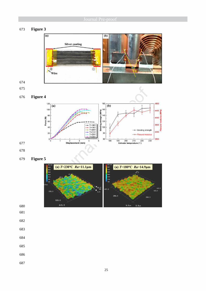
electrodes. Fig. 3a showcases a printed sample with silver coating at both ends. The CFRSMPC 147
samples were deformed to a v-shape using three-point bending grips, which were mounted on a 148
Zwick Z010 universal machine equipped with an environmental chamber, see Fig. 3b. This setup 149
was used to fix the samples in their temporary shape at 90℃ using the environmental chamber, 150
and then cooling to RT while keeping the samples under load. The electro-induced shape memory 151
effect of 4D printed CFRSMPC was characterized by resistive heating. The shape recovery 152
behavior was recorded by a video camera, and was quantified by the parameters such as recovery 153
time t and bending angle α. Besides, an infrared thermal camera (VarioCAM HiRessl, JENOPTIK 154
Infra Tec.) was used to monitor the transient temperature distribution of the specimens during 155
resistance heating. 156
2.6 Morphology characterization 157
The surface topography of CFRSMPC parts manufactured by FDM was observed using a 158
VHX-900 super depth of field digital microscope (Keyence Co., Ltd., Osaka, Japan). The surface 159
roughness Ra was calculated at four different positions for which average values were obtained, 160
and three specimens were measured under each condition. After the three-point bending test, the 161
microstructures of the fractured surfaces were observed by VEGA3 TESCAN scanning electron 162
microscopy (SEM). 163
3. Results and discussion 164
3.1 Bending performance with printing parameter 165
3.1.1 Extruder temperature T 166
Temperature is one of the critical conditions for the preparation of carbon fiber reinforced 167
polymer composites (CFRP) by 3D printing technology, which affects the impregnation of fibers 168

7
and substrate. Fig. 4a shows a schematic of the displacement-load curves generated during the 169
three-point bending test of specimens prepared under different extruder temperatures. It can be 170
seen from the graph that the load response of the specimen fabricated at 180℃ is significantly 171
lower than that of the specimens fabricated under higher temperature conditions when the same 172
displacement occurs, indicating poor mechanical performance. PLA is a semi-crystalline polymer, 173
and therefore the temperature for the 3D printing process based on FDM depends on its melting 174
temperature. The melting temperature of the PLA-based SMP filament involved in this study is 175
about 170℃. When the extruder temperature is set to 180℃, although the temperature in the 176
liquefier has reached the melting temperature of the PLA-based SMP, the flowability of the melted 177
PLA is still poor, and the impregnation between the molten matrix and the CFs is insufficient, 178
resulting in the weak mechanical performance of the printed composite parts. 179
A more intuitive illustration of the effect of extruder temperature on the bending strength and 180
flexural modulus of 4D printed CFRSMPC samples is presented in Fig. 4b. The bending 181
properties are approximately positively related to the extruder temperature T from the 180℃ to 182
230℃. The bending strength and flexural modulus increase from 97.5MPa and 3111MPa to 183
164.9MPa and 4439MPa, respectively. Through careful observation, it can be found that the 184
bending strength and flexural modulus rise rapidly in the temperature range of 180℃ to 200℃. 185
Conversely, from 200℃ to 230℃, the bending strength and flexural modulus only experience a 186
slight increase or even decrease at some specific temperature points. This phenomenon indicates 187
that when the extruder temperature reaches about 200℃, the melting degree of the PLA in the 188
liquefier has already met the requirement for manufacturing composite members with excellent 189
mechanical properties. Meanwhile, the elevated temperature may cause more serious thermal 190
oxidation degradation of the matrix, resulting in the deterioration of mechanical properties [31], 191
which can serve as an explanation for the degradation of bending strength and flexural modulus at 192
some high temperature points. Compared with the pure PLA specimens fabricated by FDM 193
process, the bending strength of the latter is about 52.6MPa to 57.9MPa within the printing 194
temperature range of 200℃ to 230℃ [32],4D printed CFRSMPC possesses prominently 195
improved bending strength. 196

8
Fig. 5a and 5b exhibit the surface topography of the printed samples at the extruder 197
temperatures of 230℃ and 180℃, respectively, which can illustrate the surface quality of the 198
parts. The surface roughness Ra of the CFRSMPC specimen printed with a temperature of 230℃ 199
is 11.1μm, which is smaller than the roughness of the sample printed at a temperature of 180℃. 200
The surface roughness data of CFRSMPC fabricated with various extruder temperatures presented 201
in Supplementary material section S1 also indicates that the higher the extruder temperature is, the 202
lower the surface roughness of 4D printed CFRSMPC components is. Similarly, Jaekel et al. [33] 203
and Wang et al. [34] reported that higher temperatures provided more energy and allowed 204
additional heating time for PEEK to crystallize, and increased crystallinity enhanced the elastic 205
modulus and yield strength of PEEK while conferring lower surface roughness. 206
3.1.2 Printing speed S 207
Fig. 6 showcases the variation in displacement-load relationships, bending strength and 208
flexural modulus of 4D printed CFRSMPC specimens manufactured using various printing speeds. 209
The increased printing speed has a different degree of unfavorable influence on the bending strength 210
and flexural modulus of the printed samples. When the printing speed is increased from 1mm/s to 211
6mm/s, the flexural modulus of the printed samples decreases significantly, which may be caused by 212
the weak bonding strength between the fiber and the matrix as a result of the insufficient melting of 213
the matrix. Moreover, as the printing speed increases, the increased flow rate of the molten matrix 214
can cause a lower inner pressure in the liquefier, which also results in a decrease in the degree of 215
impregnation of the matrix with the fibers. 216
It is anticipated that inadequate pre-impregnation between matrix and fibers and reduced 217
pressure will also weaken the fiber/matrix bonding at the interface. This hypothesis can be 218
confirmed by observing the fracture micromorphology of the samples manufactured at different 219
printing speeds shown in Fig. 7. More fibers pull-out is observed at the fracture surface of the 220
specimen manufactured with a printing speed of 6mm/s (Fig. 7b) than the sample printed with a 221
speed of 1mm/s (Fig. 7a). The pull-out of fibers from PLA causes PLA to break first, and therefore 222
the load cannot transfer to the fiber bundles, which results in a low flexural modulus of 2759MPa 223
(Fig. 6b). It can be seen from Fig. 6a and 6b that the bending strength of the printed sample is less 224

9
affected by the printing speed. This observation is consistent with previous research results [35,36]. 225
In fact, the strength of unidirectional fiber reinforced polymer composites is primarily dependent on 226
the reinforced fibers, while the printing speed affects mostly the bonding between the fibers and the 227
matrix. Fig. 8a and 8b show an increase in the mean surface roughness of the printed samples when 228
the printing speed is increased from 1mm/s to 6mm/s, indicating that the surface roughness of 4D 229
printed CFRSMPC parts is sensitive to the printing speed. When the printing speed is higher, the 230
temperature of the PLA extruded by the nozzle drops at a faster rate, leading to less time for the 231
diffusion and crystallization of the PLA molecular chain, which will increase the surface defects of 232
the printed specimen. 233
3.1.3 Extrusion width W and infill angle θ 234
The displacement-load curves, bending strength, and flexural modulus of 4D printed 235
CFRSMPC samples are exhibited in Fig. 9a and 9b as the functions of extrusion width W. As 236
shown in Fig. 2a, extrusion width W is the central distance between two adjacent deposition lines 237
extruded by the nozzle. The extrusion width directly identifies the volume fraction of CFs in the 238
printed CFRSMPC. As shown in Fig. 9b, when the extrusion width is increased from 0.9mm to 239
1.9mm, the volume content of the fiber in the printed sample is reduced from 6.19 to 2.89%, by 240
53.3%. While the average bending strength and flexural modulus decrease from 212.4MPa and 241
7397MPa to 77.3MPa and 2534MPa, with a reduction of 63.6% and 65.7%, respectively. 242
Mechanical properties are the outward manifestation of the microscopic fracture pattern. Fig. 243
10 exhibits the microscopic fracture pattern after the three-point bending test of 4D printed 244
CFRSMPC samples manufactured at various extrusion width. When bending failure occurred for 245
the sample printed with an extrusion width of 1.9mm, brittle fracture of the matrix is observed 246
from Fig. 10a, while the fiber bundles are pulled out without breaking, indicating that the fibers 247
exert little reinforcement due to poor bonding between the fibers and the matrix. Fig. 10b displays 248
the failure mode in which the fiber bundles and the matrix are almost neatly broken when the 249
flexural failure of the sample fabricated at an extrusion width of 0.9mm occurs, indicating good 250
bonding between the fibers and the matrix. In general, small extrusion width improves the 251
overlapping extent and achieves large contact pressure [35]. When extrusion width is reduced 252

10
from 1.9mm to 0.9mm, the increased contact pressure motivates more molten PLA to be 253
impregnated into the fiber bundles, improving the adhesion between the fibers and the matrix, and 254
thus enhances the mechanical performance of the printed composite parts. 255
Whether the fiber layup angle is configurable is an important indicator for evaluating 256
advanced composite manufacturing processes. The additive manufacturing process of continuous 257
carbon fiber reinforced composites proposed in this study meets the requirements of the 258
designability of fiber ply angle in advanced composite fabrication process, and laminates with 259
different fiber infill angles have been prepared, as shown in Fig. 1c. Fig. 9c introduces the 260
displacement-load curves of the printed samples with different fiber infill angles. It is noted that 261
the mechanical response of the samples is highly sensitive to the fiber infill angle. The sample 262
fabricated with infill angle of 0° has the maximum bending strength and flexural modulus, and 263
does not substantially undergo a plastic yielding stage before bending failure, but the fracture 264
strain is small. The samples printed with other fiber infill angles, especially when the infill angle is 265
45°, undergo a significant plastic deformation stage before failure. According to the experimental 266
results, the fiber layup angle during the printing process can be designed to meet the requirements 267
of the actual engineering for the mechanical properties of the printed components. 268
3.1.4 Multivariable regression analysis 269
The mathematical prediction models based on existing experimental data were developed to 270
describe the coupling effect of printing parameters on the bending properties of 4D printed 271
CFRSMPC. In this study, the multivariable quadratic regression model employed can be expressed 272
via Eq. (4) [37]. 273
20
1 1
=n n n
i i ii i ij i ji i i j
Y a a x a x a x x= = <
+ + +∑ ∑ ∑ (4) 274
Where Y represents the fitted response variable; xi and xj are independent variables; a0, ai, aii, and 275
aij are coefficients for each term, and n is the total number of independent variables. Design Expert 276
software was used to analyze the relationship between the bending responses (i.e., bending strength Σf 277
and flexural modulus Ef ) and the printing parameters (i.e., extruder temperature T, printing speed S, 278
extrusion width W and infill angle θ) to obtain the regression coefficients. The accuracy of the 279
prediction model was determined by the analysis of variance (ANOVA) method, in which the p-value 280

11
and the coefficient of determination R-squared were observed. The input experimental data was 281
presented in Supplementary material section S2. The obtained fitting results are as follows. 282
2 2
2 2
2
102.6 1.937 8.638 155.4 0.9034 0.00079 8.024
48.075 0.0058 0.1212 0.3123 0.0034
20.848 0.6243 1.475 , ( - 0.0001, 96.4%)
f T S W T S
W T S T W T
S W S W p Value R
θ
θ θθ θ
+ × − × − × − × − × + ×
+ × − × − × × − × × + × ×− × × + × × × =
=
− ×
∑
<
(5)283
2 2
2 2
2
6991.8 32.709 415.33 4903.9 28.454 0.09214 55.001
206.70 0.07235 5.2996 9.5936 0.10375
980.63 11.829 8.3416 ,( 0.0001, 97.6%)
fE T S W T S
W T S T W T
S W S W p Value R
θ
θ θθ θ
= + × − × − × − × − × + ×
+ × − × + × × + × × − × ×− × × + × × − × × − < =
(6) 284
The p-values of the models are evidently less than 0.05, which implies that the quadratic 285
model selected in this study is significant. The values of R-squared are more than 96%, indicating 286
a good agreement between the obtained prediction models and the existing experimental data. 287
Moreover, the comparison of the predicted and experimental values of the bending response 288
presented in Supplementary material section S2 also confirms the excellent agreement between the 289
experimental data and the predicted ones. 290
The response surface plot presents the relationship between the mechanical response and any 291
two model parameters in the form of a three-dimensional surface view, which assists in 292
determining the desirable mechanical response value and the corresponding process conditions. 293
Fig. 11 displays the three-dimensional surface diagrams of bending strength and flexural modulus 294
of the 4D printed CFRSMPC specimens with various printing parameters, obtained depending on 295
Eq. (5) and Eq. (6). In addition to determining the response under particular parameters by 296
positional coordinates, the color gradient corresponding to the response level can also help to 297
obtain a more intuitive response as a function of the two parameters. Besides, the solid lines on the 298
response surface are contour lines representing the coupling relationship of two variables at the 299
same response level. 300
As observed in Fig. 11a, the bending strength and flexural modulus of the specimens are 301
positively correlated with the extruder temperature, and conversely, negatively correlated with the 302
extrusion width. This is consistent with the results of previous experimental data analysis. The 303
coupling effect of extruder temperature and extrusion width on bending performance showcases a 304
diagonal law, that is, the bending strength and flexural modulus are the largest at the highest 305

12
extruder temperature and the minimum extrusion width, while the values at the lowest extruder 306
temperature and the maximum extrusion width are the smallest. A similar effect of the infill angle 307
and the extruder temperature on the bending strength of the printed sample is presented in Fig. 11b. 308
However, it is worth noting that the infill angle is the dominant factor in the coupling effect of 309
infill angle and extruder temperature on flexural modulus, while the extruder temperature 310
contributes little effect. The impact of printing speed on the bending properties of the printed 311
sample varies with other parameters. As showed in Fig. 11c, when the extrusion width W=1.9mm, 312
the bending strength of the sample increases as the printing speed decreases. However, when the 313
extrusion width is about 0.9 mm, the bending strength of the sample decreases first and then 314
increases as the printing speed decreases. In addition, it is observed from Fig. 11c that the flexural 315
modulus exhibits more conspicuous change with the extrusion width at high printing speeds than 316
at low printing speeds, which can be attributed to the impact of the prominently non-uniform 317
temperature gradient at high printing speeds [38]. 318
3.2 DMA results 319
The dynamic mechanical properties of printed pure PLA specimens and printed CFRSMPC 320
specimens were measured by DMA. Dynamic storage modulus (E') and loss tangent (Tanδ) are 321
analyzed in Fig. 12. It can be observed that the evolution curves of the storage modulus of the two 322
samples can be divided into three stages including glass state, glass transition phase and rubber 323
state, indicating that the storage modulus of pure PLA and CFRSMPC exhibits distinct variable 324
stiffness characteristics with temperature. Perhaps the difference is that the storage modulus of 325
printed CFRSMPC in the glass state is as high as 4,408 MPa, which is 2.21 times of the storage 326
modulus of printed pure PLA. This phenomenon proves that the addition of CFs not only does not 327
affect the variable stiffness characteristics of the printed samples, but also dramatically improves 328
their mechanical properties, which can expand the application prospect of 3D printing process. 329
The loss tangent is the ratio of the loss modulus to the storage modulus, which can reflect the 330
viscosity characteristics of polymers. The incorporation of fibers will cause shear stress to form 331
between the matrix and fibers, thereby reducing the additional power dissipation of the composite 332
[39]. Therefore, as expected, it can be seen from Fig. 12 that the loss tangent of the printed 333

13
CFRSMPC is significantly lower than the printed pure PLA. The temperature corresponding to the 334
peak of the loss tangent is defined as the Tg of the material. The molecular mobility of the 335
thermoplastic PLA is significantly promoted at the Tg, and the material undergoes a phase 336
transition from the glassy state to a rubbery state. It is observed that the Tg of the printed 337
CFRSMPC is 69℃, which is higher than the Tg (68℃) of the printed pure PLA. The incorporation 338
of fibers causes the Tg to shift to higher temperature, which is related to the reduced chain mobility 339
by the added fibers [40]. 340
3.3 Electro-induced shape memory behavior 341
3.3.1 Electrical actuation and shape recovery 342
4D printed CFRSMPC can be activated directly by temperature or by an electric circuit 343
through the CF bundles, which indirectly causes the electrocaloric effect. The electro-induced shape 344
memory effect of the printed CFRSMPC specimen was investigated in this study. In this process, 345
shape change was achieved by performing resistance heating under ambient pressure conditions. 346
The initial resistance of the v-shaped specimen was about 6Ω, and a voltage of 5V was applied 347
across the specimen until its shape no longer changed. Fig. 13 presents a visual description of the 348
shape recovery of the 4D printed CFRSMPC sample. The entire recovery process lasts about 75 349
seconds, and the deformation of the sample occurs mainly within 30s and 50s. The apparent shape 350
recovery process indicates that the 4D printed CFRSMPC possesses significant shape memory 351
effect, which demonstrates that the resistance heating method is an effective way to drive the sample 352
back to its initial shape 353
Compared with other 4D printed materials [18], the employment of voltage instead of the 354
direct temperature field to activate the shape recovery process is a major highlight of 4D printed 355
CFRSMPC. Due to the high electrical conductivity and electrocaloric effect, the fiber bundles 356
generate sufficient Joule heat at a specific voltage to raise the temperature of PLA-based SMP 357
above its Tg, thereby inducing the phase transition of the polymer. An infrared thermal camera was 358
employed to investigate the temperature distribution and temperature variation of 4D printed 359
CFRSMPC specimens during the electric driving. At a rated voltage of 5V, the temperature 360
distribution in 4D printed CFRSMPC specimen along with the shape recovery process is presented 361

14
in Fig. 14. According to the infrared thermal images, in addition to the low temperature region 362
caused by the more easily occurring temperature dissipation at the edge portion, the temperature 363
distribution in the specimen is relatively uniform, indicating that the electric resistance heating 364
method is stable and feasible. The temperature in the specimen shows an upward trend as a whole 365
with the energization time. The maximum temperature in the sample rises from RT to Tg of the 366
material during the first 32 seconds, so the structure experiences quite small deformation. In this 367
process, the Joule heat generated by CF bundles under the action of current diffuses into the 368
matrix, causing the temperature of the matrix to rise continuously, but the temperature is not 369
sufficient to stimulate the shape memory behavior of the shape memory polymer. Hence, the part 370
hardly undergoes deformation. When the temperature in the matrix reaches its Tg, the shape 371
memory effect of the matrix is stimulated, and the result is macroscopically expressed as rapid 372
angular changes of the v-shaped specimen. 373
Fig. 15 presents the maximum temperature and shape recovery rate of the specimen as a 374
function of the energization time. It should be mentioned that the average temperature in a specific 375
area is difficult to determine, because the shape of the specimen changes during the heating 376
process. Therefore, the evolution of the temperature with the energization time is investigated 377
based on the maximum temperature in the specimen. The shape recovery rate can be defined by 378
the following equation [41]. 379
0 n
0
100%rRα α
α−
= × (7) 380
Where Rr is the shape recovery rate of the specimen, and α0 and αn are the initial angle and the 381
real-time angle of the v-shaped sample defined according to Fig. 3b, respectively. The evolution 382
curve of the shape recovery rate with the energization time can be divided into three stages. In the 383
first stage, the shape recovery rate remains substantially unchanged, and the temperature increases 384
dramatically. In the second stage, the temperature in the specimen reaches the Tg, and the shape 385
recovery rate began to increase sharply. In the third stage, the shape recovery rate slowly increases 386
until it remains stable, and the maximum temperature in the specimen tends to be stable due to 387
heat dissipation. It can be seen from Fig. 15 that the maximum shape recovery rate of 4D printed 388
CFRSMPC specimen is above 95%, indicating that the 4D printed CFRSMPC can serve as 389

15
potential building blocks for electrically activated and deployable structures. 390
3.3.2 Deformation control through resistance measurement 391
During the shape memory test of the 4D printed CFRSMPC, changes in resistance at various 392
bending angles and temperatures were observed. The quantitative influence of the bending angle 393
and temperature on the resistance of the printed specimen was further investigated. The results 394
demonstrate that real-time monitoring of the deformation of 4D printed CFRSMPC by means of 395
resistance measurement is feasible. This methodology may be applied to future space deployable 396
structures to control their deployment process. The experimental process simulated the typical 397
thermo-mechanical cycle test method of SMP in four steps: heating, bending, cooling and recovery. 398
The resistance value of the specimen during heating, bending and cooling was directly measured 399
by a digital multimeter, while the resistance value of the specimen during the recovery process 400
was obtained by Ohm's law based on the rated voltage and the measured current. 401
Fig. 16 shows how the resistance of the 4D printed CFRSMPC varied with relevant 402
parameters at various stages of shape memory test. It can be observed from Fig. 16a that during 403
the heating stage, the resistance of the specimen exhibits a positive temperature coefficient (PTC) 404
effect. From room temperature to 90℃, the resistance increases by 0.8 Ω from 3.1Ω to 3.9Ω. The 405
PTC effect of carbon fiber reinforced thermoplastic composites has been reported [42, 43]. The 406
underlying reason for the PTC effect is the increase in the average spacing of the internal fibers 407
[42]. The continuous CF bundle embedded in the PLA is comprised of micron-sized filaments 408
with extremely small spacing from each other. The residual compressive strain derived from the 409
rapid curing of PLA during the 4D printing process causes the CF to be pushed together. During 410
the heating process, the release of residual strain and the rebound of CFs reduce the number of 411
inter-fiber contacts, which results in an increase in resistance. 412
Fig. 16b depicts the variation of resistance with the bending angle during the specimen 413
bending process at a temperature of about 90℃. During the change from the initial shape to the 414
temporary shape, the resistance of the specimen performs decreasing previously and increasing 415
later obviously. The initial decrease in the resistance results from the increased inter-fiber contacts 416
caused by fiber tension under large curvature bending. The subsequent increase in the resistance is 417
16
mainly attributed to fiber buckling and breakage induced by further bending. Fig. 17a and 17b 418
present the macroscopic and microscopic morphology of the specimens before and after bending. 419
Before bending, the surface of the specimen is flat and the fiber bundles are tightly arranged, 420
indicating that the specimen has good electrical conductivity. However, when the specimen is bent 421
into a v-shaped temporary shape, wrinkles occur in the main deformation region of the specimen, 422
demonstrating significant fiber bending and fiber buckling [44]. As shown in the optical 423
micrograph in Fig. 17b, the filaments are separated from each other as well as fibers breakage 424
occurs as a result of the unsynchronized buckling behavior of the filaments in fiber bundles, which 425
reduces inter-fiber contacts, resulting in increased electrical resistance of specimen. In addition, it 426
is generally believed that a CF microstructure primarily consists of layers of long sheets of 427
sp2-bonded carbon atoms (graphite layers) [45]. In the direction perpendicular to the graphite 428
layer, the macro-buckling of the fibers may lead to an increase in the spacing of graphite layers. 429
As a result, the density-of-state of the π electrons decreases, and higher resistance is measured as 430
electrons are forced to move a greater distance from one graphite layer to another. 431
The phenomenon of the decrease in the resistance of 4D printed CFRSMPC during the 432
cooling process observed in Fig. 16c is caused by the reverse process of the PTC effect. In fact, 433
the matrix around the fibers shrinks during cooling, reducing the spacing of the filaments from 434
each other and increasing the number of inter-fiber contacts. Fig. 16d exhibits the resistance 435
measurement of the specimen during electrical heating recovery. In the initial stage of deformation, 436
the resistance decreases dramatically by 5.6% from 6.02Ω to 5.68Ω. This dramatic reduction can 437
be attributed to the instantaneous start-up of the shape recovery process. When the temperature in 438
the specimen rises to its Tg under the action of Joule heat, the shape memory effect of the material 439
is instantaneously stimulated, and the residual stress and buckling deformation stored during the 440
bending process are released in a relatively short period of time, resulting in smaller graphite layer 441
spacing and higher density of π electrons and thus, lower resistivity. A clear comparison of the 442
macro and micro morphologies of the specimens before and after the recovery in Fig. 17b and 17c 443
can be served as proof of this interpretation. 444
Based on the previous analysis of the change in the resistance of 4D printed CFRSMPC during 445

17
the shape memory test, a phenomenological model presented in Fig. 18 is proposed to support the 446
deformation monitoring and control of the printed composite structures. The model demonstrates 447
the mechanism of the resistance change of 4D printed CFRSMPC from three hierarchies: 448
macro-structure of a printed specimen, micro-structure of CFs and molecular structure of graphite 449
layers. The macro-structure showed in Fig. 18a depicts two processes in which the specimen is bent 450
from the initial shape to the v-shaped temporary shape and then returned to the permanent shape, 451
which are respectively associated with the occurrence and release of buckling deformation. Fig. 18b 452
shows the internal contact of the filaments in the specimen. The red circles represent electrical 453
contact points that can cause excellent electrical conductivity. The CF filaments in the temporary 454
shape are separated from each other due to the buckling effect, resulting in less electrical contact 455
points and, therefore, large electrical resistance. The blue rectangular frame encircles the region 456
where fiber breakage occurs, which also results in higher resistivity. The molecular structure of the 457
graphite layers exhibited in Fig. 18c describes the change in the graphite molecular layers spacing 458
and the density-of-state of the π electrons when the macroscopic buckling of CFs occurs. The 459
spheres represent carbon atoms, the straight lines between each carbon atom represent 460
carbon-carbon covalent bonds, and the water droplet symbols among the graphite layers represent π 461
electrons that can be freely exchanged between graphite layers. As the specimen is bent from its 462
initial shape to a v-shaped temporary shape, the graphite molecular layers spacing becomes larger 463
(Hinitial < Htemporary) and the density of the π electrons which can freely move between the layers is 464
lowered, which results in a larger resistivity of the material. When the specimen is returned from the 465
temporary shape to the permanent shape, graphite molecular layers spacing becomes smaller 466
(Htemporary>Hpermanent) and the density-of-state of the π electrons increases, causing the resistivity to 467
decrease. In addition, when an external load is applied, the carbon-carbon covalent bonds in the 468
graphite layers may break, which also leads to a decrease in the electrical conductivity of the 469
material. 470
4. Summary and conclusions 471
A 3D printer based on FDM with dual feed channels was modified to fabricate CFRSMPC 472
with diverse fiber laying directions and fiber volume fractions. The three-point bending tests were 473

18
carried out to evaluate the effect of various printing parameters on the bending strength and 474
flexural modulus of 4D printed CFRSMPC. The results show that higher extruder temperatures 475
promote impregnation of the molten thermoplastic matrix with continuous CFs, resulting in higher 476
bending performance and lower surface roughness of the printed components. However,higher 477
printing speed causes weak interface bonding, implying poor mechanical response. In addition, the 478
mathematical prediction models based on existing experimental data were established to describe 479
the coupling effect of printing parameters on the bending properties of 4D printed CFRSMPC. The 480
DMA and electric heating shape recovery tests were used to characterize the variable stiffness 481
characteristic and electro-induced shape memory effect of 4D printed CFRSMPC, respectively. CF 482
bundles as the resistance heating elements generated Joule heat at a specific voltage to provide 483
sufficient thermal stimulus for the shape recovery process of the CFRSMPC. At a voltage of 5 V, 484
the deployment process of the CFRSMPC specimen was performed during 75 seconds and the 485
shape recovery rate was higher than 95%. Finally, the quantitative influence of bending angle and 486
temperature on the resistance of 4D printed CFRSMPC during the programming and recovery 487
process was further studied, and a phenomenological model was established to demonstrate the 488
mechanism of the resistance change of 4D printed CFRSMPC specimen during the bending and 489
recovery process. The results demonstrate that it is possible to monitor the real-time deformation 490
of 4D printed CFRSMPC through the resistance measurement method. This approach is expected 491
to be applied to future space deployable structures to control their deployment process. 492
In conclusion, the continuous carbon fiber reinforced shape memory polymer composite 493
fabricated by 4D printing not only overcomes the shortcomings of the traditional 3D printed 494
structures that cannot achieve active deformation, but also greatly improves the mechanical 495
strength compared with common 3D printed pure polymer or particle reinforced composite 496
structure [46-47], which can serve as key elements for electrically heated and deployable 497
structures. 4D printing technology of continuous carbon fiber reinforced shape memory polymer 498
composite is a novel manufacturing technology, and further work is needed to develop complex 499
components to enhance the application prospect of this technology. 500
Acknowledgements 501

19
This work was supported by the National Natural Science Foundation of China (Grant Nos. 502
11632005 and 11672086). 503
Reference 504
[1] Yang H, Leow WR, Wang T, Wang J, Yu J, He K, Qi D, Wan C, Chen X. 3D printed photoresponsive devices 505
based on shape memory composites. Adv Mater 2017;29:1701627. 506
[2] Wang J, Li H, Liu R, Li L, Lin Y, Nan C. Thermoelectric and mechanical properties of PLA/Bi 0·5 Sb 1·5 Te 507
3 composite wires used for 3D printing. Compos Sci Technol 2018;157:1-9. 508
[3] Gonzalez-Henriquez CM, Sarabia-Vallejos MA, Rodriguez-Hernandez J. Polymers for additive 509
manufacturing and 4D-printing: Materials, methodologies, and biomedical applications. Prog Polym Sci 510
2019;94:57-116. 511
[4] Akbari S, Sakhaei AH, Kowsari K, Yang B, Serjouei A, Zhang Y, Ge Q. Enhanced multimaterial 4D printing 512
with active hinges. Smart Mater Struct 2018;27(6):065027. 513
[5] Lui Y, Sow W, Tan L, Wu Y, Lai Y, Li H. 4D Printing and Stimuli-responsive Materials in Biomedical 514
Applications. Acta Biomater 2019;92:19-36. 515
[6] Tibbits S. 4D printing: multi-material shape change. Archit Design 2014;84(1):116-121. 516
[7] Bodaghi M, Damanpack A, Liao W. Adaptive metamaterials by functionally graded 4D printing. Mater Des 517
2017;135:26-36. 518
[8] Zhao W, Zhang F, Leng J, Liu Y. Personalized 4D printing of bioinspired tracheal scaffold concept based on 519
magnetic stimulated shape memory composites. Compos Sci Technol 2019;184:107866. 520
[9] Guo J, Zhang R, Zhang L, Cao X. 4D Printing of Robust Hydrogels Consisted of Agarose Nanofibers and 521
Polyacrylamide. ACS Macro Lett 2018;7:442-446. 522
[10] Wang W, Yu CY, Serrano PAA, Ahn SH. Soft grasping mechanisms composed of shape memory polymer 523
based self-bending units. Compos Part B Eng 2019;164:198-204. 524
[11] Zhang W, Zhang F, Lan X, Leng J, Wu AS, Bryson TM, Cotton C, Gu B, Sun B, Chou TW. Shape memory 525
behavior and recovery force of 4D printed textile functional composites. Compos Sci Technol 526
2018;160:224-230. 527
[12] Mu T, Liu L, Lan X, Liu Y, Leng J. Shape memory polymers for composites. Compos Sci Technol 528
2018;160:169-198. 529
[13] Invernizzi M, Turri S, Levi M, Suriano R. 4D printed thermally activated self-healing and shape memory 530
polycaprolactone-based polymers. Eur Polym J 2018;101:169-176. 531
[14] Michal, B. T., Spencer, E. J., & Rowan, S. J. Stimuli-responsive reversible two-level adhesion from a 532
structurally dynamic shape-memory polymer. ACS Appl Mater Interfaces 2016;8(17):11041-11049. 533
[15] Herath, HMCM, Epaarachchi JA, Islam MM, Al-Azzawi W, Leng J, Zhang, F. Structural performance and 534
photothermal recovery of carbon fibre reinforced shape memory polymer. Compos Sci Technol 535
2018;167:206-214. 536
[16] Xu Z, Ding C, Wei D, Bao R, Ke K, Liu Z, Yang M, Yang W. (2019). Electro and Light-Active Actuators 537
Based on Reversible Shape-Memory Polymer Composites with Segregated Conductive Networks. ACS Appl 538
Mater Interfaces 2019;11(33):30332-30340. 539
[17] Ze Q, Kuang X, Wu S, Wong J, Montgomery SM, Zhang R, Kovitz JM, Yang F, Qi HJ, Zhao R. Magnetic 540
Shape Memory Polymers with Integrated Multifunctional Shape Manipulation. Adv Mater 541
2019;32(4):1906657. 542
20
[18] Liu Y, Zhang F, Leng J, Wang L, Cotton C, Sun B, Chou TW. Synergistic effect enhanced shape recovery 543
behavior of metal-4D printed shape memory polymer hybrid composites. Compos Part B Eng 544
2019;179:107536. 545
[19] Liu Y, Zhang W, Zhang F, Leng J, Pei S, Wang L, Jia X, Cotton C, Sun B, Chou TW. Microstructural design 546
for enhanced shape memory behavior of 4D printed composites based on carbon nanotube/polylactic acid 547
filament. Compos Sci Technol 2019;181:107692. 548
[20] Rosales CAG, Duarte MFG, Kim H, Chave L, Hodges D, Mandal P, Lin Y, Tseng TLB. 3D printing of shape 549
memory polymer (SMP)/carbon black (CB) nanocomposites with electro-responsive toughness 550
enhancement. Mater Res Express 2018;5(6):065704. 551
[21] Zhao W, Zhang F, Leng J, Liu Y. Personalized 4D printing of bioinspired tracheal scaffold concept based on 552
magnetic stimulated shape memory composites. Compos Sci Technol 2019;184:107866. 553
[22] Lin C, Lv J, Li Y, Zhang F, Li J, Liu Y, Liu L, Leng J. 4D-Printed Biodegradable and Remotely Controllable 554
Shape Memory Occlusion Devices. Adv Funct Mater 2019;29(51):1906569. 555
[23] Ferreira RTL, Amatte IC, Dutra TA, Bürger D. Experimental characterization and micrography of 3D printed 556
PLA and PLA reinforced with short carbon fibers. Compos Part B Eng 2017;124:88-100. 557
[24] Liu T, Tian X, Zhang M, Abliz D, Li D, Ziegmann G. Interfacial performance and fracture patterns of 3D 558
printed continuous carbon fiber with sizing reinforced PA6 composites. Compos Part A Appl Sci Manuf 559
2018;114:368-376. 560
[25] Li N, Li Y, Liu S. Rapid prototyping of continuous carbon fiber reinforced polylactic acid composites by 3D 561
printing. J Mater Process Tech 2016;238:218-225. 562
[26] Heidari-Rarani M, Rafiee-Afarani M, Zahedi AM. Mechanical characterization of FDM 3D printing of 563
continuous carbon fiber reinforced PLA composites. Compos Part B Eng 2019;175:107147. 564
[27] Chacón JM, Caminero MA, Núñez PJ, García-Plaza E, García-Moreno I, Reverte JM. Additive manufacturing 565
of continuous fibre reinforced thermoplastic composites using fused deposition modelling: Effect of process 566
parameters on mechanical properties. Compos Sci Technol 2019;181:107688. 567
[28] Sugiyama K, Matsuzaki R, Ueda M, Todoroki A, Hirano Y. 3D printing of composite sandwich structures 568
using continuous carbon fiber and fiber tension. Compos Part A Appl Sci Manuf 2018;113:114-121. 569
[29] Liu T, Liu L, Zeng C, Liu Y, Leng J. 4D printed anisotropic structures with tailored mechanical behaviors and 570
shape memory effects. Compos Sci Technol 2020;186:107935. 571
[30] Caminero MA, Chacón JM, Garcia-Moreno I, Rodriguez GP. Impact damage resistance of 3D printed 572
continuous fibre reinforced thermoplastic composites using fused deposition modelling. Compos Part B Eng 573
2018;148:93-103. 574
[31] Ding Q, Li X, Zhang D, Zhao G, Sun Z. Anisotropy of poly (lactic acid)/carbon fiber composites prepared by 575
fused deposition modeling. J Appl Polym Sci 2019:48786. 576
[32] Kuznetsov VE, Solonin AN, Tavitov A, Urzhumtsev O, Vakulik A. Increasing strength of FFF 577
three-dimensional printed parts by influencing on temperature-related parameters of the process. Rapid 578
Prototyping J 2020;26(1): 107-121. 579
[33] Jaekel DJ, MacDonald DW, Kurtz SM. Characterization of PEEK biomaterials using the small punch test. J 580
Mech Behav Biomed Mater 2011;4:1275-1282. 581
[34] Wang P, Zou B, Xiao H, Ding S, Huang C. Effects of printing parameters of fused deposition modeling on 582
mechanical properties, surface quality, and microstructure of PEEK. J Mater Process Technol 583
2019;271:62-74. 584
21
[35] Tian X, Liu T, Yang C, Wang Q, Li D. Interface and performance of 3D printed continuous carbon fiber 585
reinforce of PLA composites. Compos Part A Appl Sci Manuf 2016;88:198-205. 586
[36] Huang B, Meng S, He H, Jia Y, Xu Y, Huang H. Study of processing parameters in fused deposition modeling 587
based on mechanical properties of acrylonitrile‐ butadiene‐ styrene filament. Polym Eng Sci 588
2019;59(1):120-128. 589
[37] Hu Q, Duan Y, Zhang H, Liu D, Yan B, Peng F. Manufacturing and 3D printing of continuous carbon fiber 590
prepreg filament. J Mater Sci Composites 2018;53(3):1887-1898. 591
[38] Luzanin O, Guduric V, Ristic I, Muhic S. Investigating impact of five build parameters on the maximum 592
flexural force in FDM specimens–a definitive screening design approach. Rapid Prototyping J 593
2017;23(6):1088–1098. 594
[39] Cordeiro EP, Pita VJ, Soares BG. Epoxy–fiber of peach palm trees composites: the effect of composition and 595
fiber modification on mechanical and dynamic mechanical properties. J Polym Environ 2017;25(3):913-924. 596
[40] Pothan LA, Oommen Z, Thomas,S . Dynamic mechanical analysis of banana fiber reinforced polyester 597
composites. Compos Sci Technol 2003;63(2):283-293 598
[41] Li M, Wu J, Song F, Li D, Wang X, Chen L, Wang Y. Flexible and electro-induced shape memory Poly(Lactic 599
Acid)-based material constructed by inserting a main-chain liquid crystalline and selective localization of 600
carbon nanotubes. Compos Sci Technol 2019;173:1-6. 601
[42] Zhang R, Tang P, Li J, Xu D, Bin Y. Study on filler content dependence of the onset of positive temperature 602
coefficient (PTC) effect of electrical resistivity for UHMWPE/LDPE/CF composites based on their DC and 603
AC electrical behaviors. Polymer 2014;55(8):2103-2112. 604
[43] Zhang X, Zheng X, Ren D, Liu Z, Yang W, Yang M. Unusual positive temperature coefficient effect of 605
polyolefin/carbon fiber conductive composites. Mater Lett 2016;164:587-590. 606
[44] Lan X, Liu L, Liu Y, Leng J. Post microbuckling mechanics of fibre-reinforced shape-memory polymers 607
undergoing flexure deformation. Mech Mater 2014;72:46-60. 608
[45] Joshi K, Arefev MI, Zhigilei LV. Generation and characterization of carbon fiber microstructures by atomistic 609
simulations. Carbon 2019;152:396-408. 610
[46] Liu H, He H, Peng X, Huang B, Li J . Three-dimensional printing of poly (lactic acid) bio‐based composites 611
with sugarcane bagasse fiber: Effect of printing orientation on tensile performance. Polym Advan Technol 612
2019;30(4):910-922. 613
[47] Wu W, Jiang J, Jiang H, Liu W, Li G, Wang B, Tang M, Zhao, J. Improving bending and dynamic mechanics 614
performance of 3D printing through ultrasonic strengthening. Mater Lett 2018;220:317-320. 615

22
Figure Captions 616
Fig. 1. Schematic of fabricating continuous carbon fiber reinforced polymer composites with a modified 617
multi-material 3D printer based on FDM technology. 618
Fig. 2. Structural parameters of 4D printed CFRSMPC. a) Various fiber extrusion width. b) Various fiber 619
infill angle. 620
Fig. 3. a) 4D printed CFRSMPC specimen with silver coating on both ends as electrodes. b) Temporary 621
shape and deformation angle of the specimen after being shaped. 622
Fig. 4. Under the experimental conditions of S=3mm/s, W=1.5mm and θ=0°: a) displacement-load 623
curves of 4D printed CFRSMPC specimens fabricated at various extruder temperatures; b) the effect of 624
extruder temperature on the bending strength and flexural modulus of the printed CFRSMPC. 625
Fig. 5. Surface topography of the printed specimens fabricated at the extruder temperature of a) 230℃ 626
and b) 180℃, respectively. 627
Fig. 6. Under the experimental conditions of T=210℃, W=1.5mm and θ=0°: a) Displacement-load 628
curves of 4D printed CFRSMPC specimens fabricated at various printing speed. b) The effect of printing 629
speed on the bending strength and flexural modulus of the printed CFRSMPC. 630
Fig. 7. Micromorphology of fracture surface after three-point bending test of the printed specimens with 631
printing speed of a) 1mm/s and b) 6mm/s. 632
Fig. 8. Surface topography of the printed specimens fabricated at the printing speed of a) 1mm/s and b) 633
6mm/s, respectively. 634
Fig. 9. The variation in a) displacement-load curves,b) flexural modulus and bending strength of the 635
specimens printed with various extrusion width under other experimental conditions of T=210℃, 636
S=3mm/s and θ=0°. c) Displacement-load curve, d) flexural modulus and bending strength of the printed 637
specimens with different extrusion widths under other experimental conditions such as T=210℃ , 638
S=3mm/s and W=1.5mm. 639
Fig. 10. Representative SEM images of the fracture surface after the three-point bending test of 640

23
composite samples printed at the extrusion width of a) 1.9mm and b) 0.9mm. 641
Fig. 11. 3D surface graphs of the relationship between printing parameters and bending properties 642
including bending strength and flexural modulus. The graphs were presented when a) S=1mm/s and θ=0°, 643
b) S=1mm/s and W=0.9mm, and c) T=230℃ and θ=0°. 644
Fig. 12. Storage modulus and loss tangent of two kinds of printed materials. 645
Fig. 13. Snapshot of Joule heating-induced shape recovery in 4D printed CFRSMPC. 646
Fig. 14. Snapshots of shape recovery and temperature distribution of 4D printed CFRSMPC specimen 647
during resistance heating. 648
Fig. 15. Temperature changes and rotation angle α versus heating time during the shape recovery process 649
for 4D printed CFRSMPC 650
Fig. 16. The resistance of 4D printed CFRSMPC specimen changes with the relevant parameters during 651
the shape memory test. a) Resistance versus temperature during the heating stage. b) Resistance versus 652
bending angle α during the bending stage. c) Resistance versus temperature during the cooling stage. d) 653
Resistance versus bending angle α during the recovery stage. 654
Fig. 17. The macrostructure of 4D printed CFRSMPC specimens in the shape memory test process and 655
the microscopic morphology of the carbon fiber observed with an optical microscope. a) Specimen with 656
the rectangular initial shape before bending. b) Specimen with V-shaped temporary shape in which 657
obvious fiber buckling deformation occurred after bending. c) Specimen with permanent shape after 658
recovery. 659
Fig. 18. The phenomenological model, which demonstrates the mechanism of resistance change during 660
bending and recovery of 4D printed CFRSMPC from three levels: (a) macro-structure level, (b) 661
micro-structure level of CF and (c) graphite sheets molecular level.662

24
Figures 663
Figure 1 664
665
666
Figure 2 667
668
669
670
671
672
25
Figure 3 673
674
675
Figure 4 676
677
678
Figure 5 679
680
681
682
683
684
685
686
687

26
Figure 6 688
689
690
Figure 7 691
692
693
Figure 8 694
695
696

27
Figure 9 697
698
699
Figure 10 700
701
702
703
704
705

28
Figure 11 706
707
708
Figure 12 709
710
711
712
713

29
Figure 13 714
715
716
Figure 14 717
718
719
720
721
722
723
724

30
Figure 15 725
726
727
Figure 16 728
729
730
731
732
733
734
735
736

31
Figure 17 737
738
739
Figure 18 740
741

Declaration of interests
The authors declare that they have no known competing financial interests or personal
relationships that could have appeared to influence the work reported in this paper.