49-80635-1 review3 en hires - ge appliances
TRANSCRIPT
49-80635-1 03-15 GE
GEAppliances.com
Safety Information . . . . . . . . . . . . 2
Warranty . . . . . . . . . . . . . . . . . . . . . . . . 4
Assistance / Parts and Accessories . . . . . . . . . 5
Using The CooktopCooktop Features . . . . . . . . . . . . . . . . . . 6Surface Burners . . . . . . . . . . . . . . . . . . . . 7Cookware for Radiant Glass Cooktop . . . . . . . . . . . . . . . . . . . . 9For Best Results . . . . . . . . . . . . . . . . . . . . 9
Care and CleaningCleaning The Cooktop . . . . . . . . . . . . .10Cleaning the Glass Cooktop . . . . . . . .11
Installation Instructions . . . . . .13
Troubleshooting Tips . . . . . . . . .25
Cook
top
Radi
ant D
ownd
raft
Write the model and serial numbers here:
Model # ______________________
Serial # _______________________
Find these numbers on a label under the cooktop, on the side of the vent chamber.
For a Spanish version of this manual, visit our Website at GEAppliances.com.
Para consultar una version en español de este manual de instrucciones, visite nuestro sitio de internet GEAppliances.com.
Owner’s Manual & Installation Instructions
PP9830

2 49-80635-1
SAVE THESE INSTRUCTIONS
Read all safety instructions before using the product. Failure to follow these instructions may result in fire, electric shock, serious injury or death.WARNING
IMPORTANT SAFETY INFORMATION.READ ALL INSTRUCTIONS BEFORE USING.
SAFE
TY IN
FORM
ATIO
N
described in this Owner’s Manual.
grounded by a qualified installer in accordance with the provided installation instructions.
your range unless it is specifically recommended in this manual. All other servicing should be referred to a qualified technician.
cooktop or disconnect the power supply at the household distribution panel by removing the fuse or switching off the circuit breaker.
not be left alone or unattended in an area where an appliance is in use. They should never be allowed to climb, sit or stand on any part of the appliance.
CAUTION:
on the cooktop to reach items could be seriously injured.
holders on hot surfaces may result in burns from
other bulky cloth in place of pot holders.
the room.
surfaces may be hot enough to burn even though
do not touch, or let clothing or other flammable materials contact the surface units or areas nearby the surface units; allow sufficient time for cooling first. Other surfaces of the appliance may become hot enough to cause burns. Potentially hot surfaces include the cooktop and areas facing the cooktop.
could build up and the container could burst, causing an injury.
at least an internal temperature of 160°F and poultry to at least an internal temperature of
protects against foodborne illness.
exhausting of gases through the flue (chimney) of fuel burning equipment to prevent back drafting. Follow the heating equipment manufacturer’s guide lines and safety standards, such as
applicable, install any make up (replacement) air system in accordance with local building
available makeup air solutions
cooktop, including paper, plastic, pot holders, linens, wall coverings, curtains, drapes and gasoline or other flammable vapors and liquids.
using the appliance. These garments may ignite if they contact hot surfaces causing severe burns.
materials accumulate on or near the cooktop. Grease on the cooktop may ignite.
not be allowed to accumulate on the hood or filter.
GENERAL SAFETY INSTRUCTIONS
KEEP FLAMMABLE MATERIALS AWAY FROM THE COOKTOP.
WARNING
WARNING
49-80635-1 3SAVE THESE INSTRUCTIONS
SAFETY IN
FORM
ATION
greasy spillovers that may catch on fire.
to heat beyond its smoking point, oil may ignite resulting in fire that may spread to surrounding
possible to monitor oil temperature.
cooking frozen foods with excessive amounts of ice.
flat bottoms large enough to cover the surface heating element. The use of undersized cookware will expose a portion of the surface unit to direct contact and may result in ignition of clothing. Proper relationship of cookware to surface unit will also improve efficiency.
earthenware or other glazed containers are suitable for cooktop service; others may break because of the sudden change in temperature.
flammable materials and spillage, the handle of a container should be turned toward the center of the range without extending over nearby surface units.
the fan on.
surface of the cooktop will retain heat after the controls have been turned off.
can be scratched with items such as knives, sharp instruments, rings or other jewelry, and rivets on clothing.
cooktop should break, cleaning solutions and spillovers may penetrate the broken cooktop and
technician immediately.
fire on the glass cooktop, even when it is not
on, they may ignite. Heat from the cooktop after it is turned off may cause them to ignite also.
®
®
the indicator light goes out before cleaning. A wet sponge or cloth on a hot surface can cause
noxious fumes if applied to a hot surface.
should be scraped off while still hot using an
glass cooktop section for detailed instructions.
the cleaning cream label.
flaming pan on a surface unit by covering the
RADIANT COOKTOP SAFETY INSTRUCTIONS
IN THE EVENT OF A FIRE, TAKE THE FOLLOWING STEPS TO PREVENT THE FIRE FROM SPREADING:
WARNING
WARNING

4 49-80635-1
GE Radiant Cooktop WarrantyGEAppliances.com
® technician.
(800.432.2737). Please have serial number and model number available when calling for service.
What GE will not cover:
the product.
Failure of the product if it is abused, misused, modified or used for other than the intended purpose or used commercially. Replacement of house fuses or resetting of circuit breakers.
floods or acts of God.
possible defects with this appliance.
Product not accessible to provide required service.
air system.
EXCLUSION OF IMPLIED WARRANTIES
including the implied warranties of merchantability or fitness for a particular purpose, are limited to one year or the shortest period allowed by law. This warranty is extended to the original purchaser and any succeeding owner for products purchased for home use
specific legal rights, and you may also have other rights which vary from state to state. To know what your legal rights are, consult your local or state consumer affairs office or your state’s Attorney General.
Warrantor: General Electric Company. Louisville, KY 40225
Extended Warranties:
warranty expires.
Register Your Appliance:
Timely product registration will allow for enhanced communication and prompt service under the terms of your warranty,
date
is n
eede
d to
obt
ain
serv
ice
unde
r the
war
rant
y.W
ARR
AN
TY Thank You! ... for your purchase of a GE Brand appliance.

49-80635-1 5
Schedule Service:
business hours.Parts and Accessories: their own appliances can have parts or accessories sent
every day or by phone at 800.626.2002 during normal business hours.
to be performed by any user. Other servicing generally
must be exercised, since improper servicing may cause unsafe operation.
Real Life Design Studio:
that can be used by people of all ages, sizes and
range of physical and mental abilities and impairments.
including kitchen design ideas for people with disabilities,
Contact Us:
General Manager, Customer RelationsGE Appliances, Appliance Park Louisville, KY 40225
www.geappliances.com/service_and_support/) 24 hours a day, any day of the
Parts and Accessorieswww.GEApplianceParts.com www.GEAppliances.ca
or call 800.626.2002 800.661.1616
How to Remove Protective Shipping Film and Packaging Tape
with your fingers and slowly peel it from the appliance
Remove all of the film before using the appliance for the first time.
To assure no damage is done to the finish of the product, the safest way to remove the adhesive from packaging tape on new appliances is an application of a household liquid dishwashing detergent. Apply with a soft cloth and allow to soak.NOTE:cannot be removed if it is baked on.
Parts
Cleaning Supplies
®
®
®
®
Have a question or need assistance with your appliance? A
SSISTAN
CE / PA
RTS AN
D ACC
ESSORIES

6 49-80635-1
1. Left Rear Surface Unit2. Bridge Surface Unit3. Left Front Surface Unit4. Vent Grille5. Vent Filter (below the vent grille)6. Right Rear Surface Unit7. Dual Surface Unit8. Model and Serial Number Label (under the
cooktop, on the right side of the vent chamber)9. Left Rear Surface Unit Control10. Left Front Surface Unit Control11. Left Side Hot Surface Indicator Lights
(one for each surface unit)12. Vent Fan Speed Control13. Control Lock Knob14. Right Side Hot Surface Indicator Lights
(one for each surface unit)15. Dual Surface Unit Control16. Right Rear Surface Unit Control17. Surface Unit On Indicator Light
Throughout this manual, features and appearance may vary from your model.
Cooktop FeaturesU
SIN
G T
HE
COO
KTO
P: C
ookt
op F
eatu
res
Feature Index (Features and appearance may vary)
4 51 6
3 7 8
2
9
13
17
12
11
10 15
16
14

49-80635-1 7
Surface BurnersU
SING
THE CO
OKTO
P: Surface Burners
Radiant Surface UnitsThe control for the radiant surface unit can be set anywhere between LO and HI for an unlimited number
and off to maintain your selected control setting.To bring liquids to a boil faster, use a lid to cover the pan.The control knob must be pushed down and turned from the OFFany position other than off, they may be turned without pushing down.
OFF position.
The surface unit ON indicator light will glow when any surface unit is on.The HOT surface indicator light will glow when the glass surface is hot and will remain on until the surface has cooled.
About the radiant surface unitsThe radiant cooktop features heating units beneath a smooth glass surface.NOTE: A slight odor is normal when a new cooktop is
parts and insulating materials and will disappear in a short time. NOTE: On models with light colored glass cooktops, it is normal for the cooking zones to change color when hot or cooling down. This is temporary and will disappear as the glass cools to room temperature.The surface unit will cycle on and off to maintain your selected control setting.
on the glass surface when the surface is cool.
cooktop retains enough heat to continue cooking. To
when the food is cooked. Avoid placing anything on the surface unit until it has cooled completely.
the cleaning cream or full strength white vinegar.
on the cooktop. The cleaning cream will remove this discoloration.
drop onto the cooktop, they can cause damage.
Never cook directly on the glass. Always use cookware.
Always place the pan in the center of the surface unit you are cooking on.
Do not slide cookware across the cooktop because it can scratch the glass. The glass is scratch-resistant, not scratchproof.
Be sure you turn the control knob to OFF when you finish cooking.
SURFACE COOKING
OFF CENTER
DRAGGING

8 49-80635-1
Surface Burners (Cont.)U
SIN
G T
HE
COO
KTO
P: S
urfa
ce B
urne
rs
Dual Surface UnitThe right front surface unit has 2 cooking sizes to select from so you can match the size of the unit to the size of the cookware you are using.
clockwise to and select the desired setting. The unit will heat the entire area contained by the larger circle.
surface unit, turn the knob counterclockwise to and select the desired setting. The unit will only heat the area inside the smaller circle.
Bridge Surface UnitMake sure the pan rests flat on the glass cooktop and
performance, move the pan to make sure it is flat on the cooktop.
To use the bridge burner, turn the burner knob to and select the desired setting. The unit will heat the front surface burner and the bridge.
as possible.
To use only the front surface unit, turn the burner knob to and select the desired setting. The unit will only heat the front surface burner.
heated area by using the left rear unit in addition to the front unit bridge combination.
Surface Elements Cycle On and Off
temperature you have selected.All radiant surface elements have a temperature limiter that protects the glass cooktop from getting too hot.
The temperature limiter may cycle the elements off
Temperature Limiter
The temperature limiter protects the glass cooktop from getting too hot.
The temperature limiter may cycle the units off for a
Control Lock-Out for Surface Units
to LOCK. This will prevent surface units from heating. An indicator light will glow to show that they are locked. The downdraft fan will remain operable with control lockout engaged.
will produce an audible sound if any surface unit control knob is engaged or moved to a position other than OFF.
How to Operate the Vent System
odors and smoke from foods prepared on the cooktop. To operate the downdraft vent system, turn the vent fan speed control knob to HI, MED or LO, as needed.
cooking helps keep the kitchen comfortable and less humid, reducing cooking odors and soiling moisture that normally creates a frequent need for cleaning.
Small 6" surface unit setting
Large 9" surface unit setting
Front Burner and Bridge
Front Burner only

49-80635-1 9
Cookware for Radiant Glass CooktopU
SING
THE CO
OKTO
P: Cookware for Radiant G
lass Cooktop / For Best Results
For Best Results
NOTE: Follow all cookware manufacturer’s recommendations when using any type of cookware on the ceramic cooktop.
The following information will help you choose cookware which will give good performance on glass cooktops.
Stainless Steel:recommended
Aluminum:heavy weight recommendedGood conductivity. Aluminum residues sometimes appear as scratches on the cooktop but can be removed if cleaned
thin weight aluminum should not be used.
Copper Bottom:recommended
appear as scratches. The residues can be removed, as long as the cooktop is cleaned immediately. However, do not let these pots boil dry. Overheated metal can bond to glass cooktops. An overheated copper bottom pot will leave a residue that will permanently stain the cooktop if not removed immediately.
Porcelain Enamel on Cast Iron:recommended if bottom of pan is coated
Porcelain Enamel on Steel:not recommendedHeating empty pans can cause permanent damage to cooktop glass. The enamel can melt and bond to the ceramic cooktop.
Glass-ceramic:not recommended
Stoneware:not recommendedPoor performance. May scratch the surface.
Cast Iron:
specifically for glass cooktopsPoor conductivity and slow to absorb heat.
place lids on the surface elements, particularly wet lids.
wok will not heat on glass surface elements.
wok. They are available at your local retail store. The bottom of the wok should have the same diameter as the surface element to ensure proper contact.
etc. All cookware must have flat bottoms and be the correct size.Avoid allowing foods to boil dry as some cookware may stick to the cooking surface, causing permanent damage to the cooktop.
Check pans for flat bottoms by using a straight edge.
Pans with rounded, curved, ridged or warped bottoms are not recommended.
Do not place wet pans on the glass cooktop.
Do not use woks with support rings on the glass cooktop.
Use flat-bottomed woks on the glass cooktop.

10 49-80635-1
Cleaning The CooktopC
ARE
AN
D C
LEA
NIN
G: C
lean
ing
The
Cook
top
Vent Grille
blower is turned off.To clean the vent grille, remove it from the cooktop by
the vent grille can be washed in the sink.
They will damage the vent grille’s finish.
the dishwasher.
Vent Filter and ChamberThe filter is held in place at an angle with a hold bump. Lift the filter up and out of the vent opening diagonally.To clean the filter, swish it in hot, soapy water. Rinse well and dry thoroughly.Do not operate the vent without the filter in place.
Do not operate the vent without the filter in place.
To clean the vent chamber, use hot, soapy water. Rinse
cleaners; they will damage the finish. Replace the filter after it is cleaned and dry.
Remove and replace the filter diagonally through the vent opening.
To order replacement filters, see the Assistance / Parts and Accessories section.
Control KnobsThe control knobs may be removed for easier cleaning.Make sure the knobs are in the Off positions and pull them straight off the stems for cleaning.To clean the knobs, place them in a dishwasher or wash with soap and water. Rinse with clean water. Make sure the insides of knobs are dry before replacing.Replace the knobs in the Off position to ensure proper placement.
Stainless Steel Surfaces (on some models)
To clean the stainless steel surface, use warm sudsy water or a stainless steel cleaner or polish. Always wipe the surface in the direction of the grain. Follow the cleaner instructions for cleaning the stainless steel surface.
To inquire about purchasing cleaning products including stainless steel appliance cleaner or polish read the
beginning of this manual.
Vent Chamber
Vent Filter
When replacing the filter, make sure it rests, at an angle, on the supports in the vent opening.
Shaped area

49-80635-1 11
Use a CERAMA BRYTE® Cleaning Pad for Ceramic Cooktops.
Normal Daily Use Cleaning®
be as effective.To maintain and protect the surface of your glass
®
This helps protect the top and makes cleanup easier.®
3. Remove the burner grates, vent grille and vent grille gasket.
®
to the cooktop.
®
to clean the entire cooktop surface.
to remove all cleaning residue.
NOTE:
until it has been cleaned thoroughly.
Burned-On ResidueNOTE:use scrub pads other than those recommended.1. Allow the cooktop to cool.2. Remove the burner grates, vent grille and vent grille
®
residue area.®
pressure as needed.
as needed.
been removed, polish the entire surface with ®
and a paper towel.
Clean your cooktop after each spill. Use CERAMA BRYTE® Ceramic Cooktop Cleaner.
CA
RE AN
D C
LEAN
ING
: Cleaning The Cooktop / Cleaning the Glass Cooktop
Cleaning the Glass Cooktop
Heavy, Burned-On Residue1. Allow the cooktop to cool.2. Remove the burner grates, vent grille and vent grille
gasket.
scraper in order to remove the residue.4. After scraping with the razor scraper, spread a few drops
®
®
®
The CERAMA BRYTE® Ceramic Cooktop Scraper and all recommended supplies are available through our Parts Center. See Assistance / Parts And Accessories section.
NOTE: Do not use a dull or nicked blade.
12 49-80635-1
CA
RE A
ND
CLE
AN
ING
: Cle
anin
g th
e G
lass
Coo
ktop Cleaning the Glass Cooktop
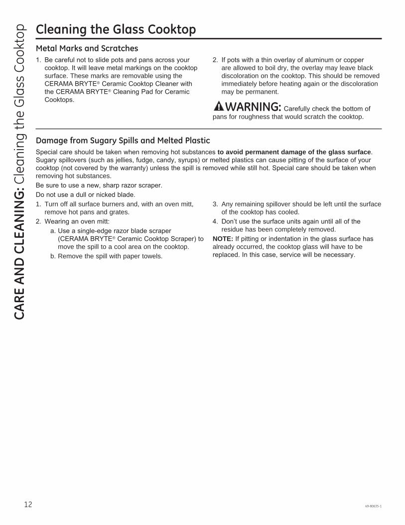
Metal Marks and Scratches
surface. These marks are removable using the ®
®
are allowed to boil dry, the overlay may leave black discoloration on the cooktop. This should be removed immediately before heating again or the discoloration may be permanent.
WARNING: pans for roughness that would scratch the cooktop.
Damage from Sugary Spills and Melted Plasticto avoid permanent damage of the glass surface.
removing hot substances.
1. Turn off all surface burners and, with an oven mitt, remove hot pans and grates.
®
move the spill to a cool area on the cooktop. b. Remove the spill with paper towels.
3. Any remaining spillover should be left until the surface of the cooktop has cooled.
residue has been completely removed.NOTE:already occurred, the cooktop glass will have to be

49-80635-1 13
Installation Radiant Downdraft Cooktop
Instructions PP9830
“If you have questions, call 800.GE.CARES or visit our website at: GEAppliances.com”
INSTA
LLATION
INSTRU
CTIO
NS
BEFORE YOU BEGINRead these instructions completely and carefully.
• IMPORTANT – Save these instructions for local inspector’s use.
• IMPORTANT – Observe all governing codes and ordinances.
• Note to Installer – Be sure to leave these instructions with the Consumer.
• Note to Consumer – Keep these instructions for future reference.
• Unless very knowledgeable in the installation of this product, engage a professional installer.
• Proper installation is the responsibility of the installer. • Product failure due to improper installation is not
covered under the Warranty.
WARNING – Before beginning the installation, switch power off at the service panel and lock the service disconnecting means to prevent power from being switched on accidentally. When the service disconnecting means cannot be locked, securely fasten a prominent warning device, such as a tag, to the service panel.
WARNING – TO REDUCE THE RISK OF FIRE, USE ONLY METAL DUCTWORK.
IMPORTANT SAFETY INSTRUCTIONSWARNING – TO REDUCE THE RISK
OF FIRE, ELECTRIC SHOCK OR INJURY TO PERSONS, OBSERVE THE FOLLOWING: A Installation work and electrical wiring must be done
by qualified person(s) in accordance with all applicable codes and standards, including fire-rated construction.
B Sufficient air is needed for proper combustion and exhausting of gases through the flue (chimney) of fuel burning equipment to prevent back drafting. Follow the heating equipment manufacturer’s guidelines and safety standards such as those published by the National Fire Protection Association (NFPA), and the American Society for Heating, Refrigeration and Air Conditioning Engineers (ASHRAE), and the local code authorities.
C When cutting or drilling into wall or ceiling, do not damage electrical wiring and other hidden utilities.
D Ducted fans must always be vented to the outdoors. • This unit must be properly grounded.
EXHAUST BLOWER RATINGS
EXHAUST BLOWER SAFETY WARNINGSufficient air is needed for proper combustion and exhausting of gases through the flue (chimney) of fuel burning equipment to prevent back drafting. Follow the heating equipment manufacturer’s guide lines and safety standards, such as those published by the National Fire Protection Association (NFPA), the American Society for Heating, Refrigeration and Air Conditioning (ASHRAE) and the local code authorities. when applicable, install any make up (replacement) air system in accordance with local building code requirements. Visit GEAppliances.com for available makeup air solutions.
14 49-80635-1
INST
ALL
ATIO
N IN
STRU
CTI
ON
S Installation Instructions
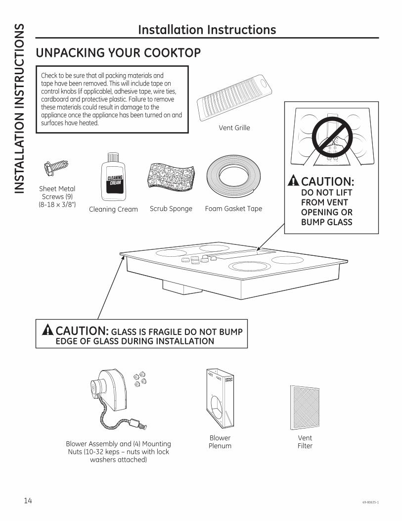
UNPACKING YOUR COOKTOP
Vent Grille
Cleaning Cream Scrub Sponge
Sheet Metal Screws (9)
(8-18 x 3/8") Foam Gasket Tape
Blower Assembly and (4) Mounting Nuts (10-32 keps – nuts with lock
washers attached)
Blower Plenum
Vent Filter
CAUTION: DO NOT LIFT FROM VENT OPENING OR BUMP GLASS
Check to be sure that all packing materials and tape have been removed. This will include tape on control knobs (if applicable), adhesive tape, wire ties, cardboard and protective plastic. Failure to remove these materials could result in damage to the appliance once the appliance has been turned on and surfaces have heated.
CAUTION: GLASS IS FRAGILE DO NOT BUMP EDGE OF GLASS DURING INSTALLATION

49-80635-1 15
INSTA
LLATION
INSTRU
CTIO
NS
Installation Instructions
PREPARATION
30" COOKTOP (DIMENSIONS FOR REFERENCE ONLY)Unit shown fully assembled.
Unit must be vented to the outside!
TOOLS AND MATERIALS YOU WILL NEED• Cut resistant gloves• Saw• Flat-blade screwdriver• Electrician’s pliers• Duct tape• Measuring tape or scale• Carpenter’s square• 7/16” wrench or socket set• Drill and drill bit• Sheet metal screws• Junction box*• 3/4” flexible conduit*• Electrical wire per local code*• Wire nuts*• Ductwork* NOTE: Electrical installation kit JXCK89 may be ordered separately and includes all the parts necessary to connect the cooktop to typical rough-in wiring.
ELECTRICAL REQUIREMENTSThis appliance must be supplied with the proper voltage and frequency, as listed in these Installation Instructions, and connected to an individual, properly grounded branch circuit, protected by a 40-amp circuit breaker or time delay fuses. All wire connections must be made in accordance with local codes and properly insulated. Check with your local utility for governing electrical codes and ordinances. In the absence of local electrical codes, the National Electrical Code, ANSI/NFPA No. 70 – Latest Edition, governing electric range installations, must be followed. A copy of the National Electrical Code can be obtained by writing to: National Fire Protection Association Batterymarch Park Quincy, MA 02260Effective January 1, 1996, the National Electrical Code requires that new, but not existing, construction utilize a four-conductor connection to an electric range. When installing an electric range in new construction, follow the instructions in NEW CONSTRUCTION AND FOUR-CONDUCTOR BRANCH CIRCUIT CONNECTION.You must use a three-wire, single-phase AC 208Y/120 Volt or 240/120 Volt, 60 Hertz electrical system with separate ground. If you connect to aluminum wiring, properly installed connectors approved for use with aluminum wiring must be used.
CAUTION: FOR PERSONAL SAFETY, REMOVE HOUSE FUSE OR OPEN CIRCUIT BREAKER BEFORE PREPARING JUNCTION BOX.
201 2”
22”
283 4”
23 16”(21 4” SS)
217 8”(2115 16” SS)
2923 32”(2913 16” SS)

16 49-80635-1
INST
ALL
ATIO
N IN
STRU
CTI
ON
S Installation Instructions
CABINET PREPARATION
1 PREPARING FOR INSTALLATIONPositioning the cooktopThe cooktop is designed to look best when centered in a cabinet at least 30” wide.The exhaust vent beneath the cooktop must be located between wall studs or floor joists so that the ductwork may be installed properly.At least 6” must be allowed between side edges of the cooktop and adjacent walls.
Avoid placing cabinets above the cooktop unit, if possible, in order to reduce the hazards caused by reaching over heated surface units. If cabinets are placed over the cooktop, the risks can be reduced by installing a range hood that projects horizontally a minimum of 5 inches beyond the bottom of the cabinets.If cabinetry is used above the cooktop, allow a minimum 30” clearance between the cooking surface and the bottom of any unprotected cabinet.If the clearance between the cooktop and the cabinetry is less than 30”, the cabinet bottom must be protected with flame retardant millboard at least 1/4” thick, covered with 28 gauge sheet steel or 0.020” thick copper. Clearance between the cooktop and the protected cabinetry MUST NEVER BE LESS THAN 24 ". EXCEPTION: Installation of a listed microwave oven or cooking appliance over the cooktop shall conform to the installation instructions packed with that appliance.A 15” minimum must be kept from the side edge of the cooktop to the bottom of any cabinet not directly above the cooktop. If the clearance is less than 15”, adjacent cabinets should be at least 6” from the side edge of the cooktop.
3 ROUGH PREPARATION OF JUNCTION BOX
CAUTION: FOR PERSONAL SAFETY, REMOVE HOUSE FUSE OR OPEN CIRCUIT BREAKER BEFORE PREPARING JUNCTION BOX.Install an approved junction box within shaded area shown
of cabinet.Run conductors from residence wiring to junction box according to local electrical codes.
2 PREPARING THE BASE CABINETThis cooktop is designed to fit easily into a variety of cabinets. However, some cabinets may require modifications.
Preparing a cabinet that is against a wallIn some cabinets, the sides may need to be scooped or cut down 53/4” as shown, and the corner braces removed in order to accommodate the unit.In 75 cm and 90 cm frameless European cabinets, the back panel may need to be cut down 53/4” to accommodate the unit.Preparing a peninsula or island-type cabinetIn a peninsula or island-type cabinet, the sides may need to be scooped or cut down, and the corner braces removed in order to accommodate the unit.
13" max. depth of
unprotected overhead cabinets
6" min. clearance from cutout to
side walls
30" min. clearance from countertop to unprotected
overhead surface
15" min. height from countertop to nearest cabinet on
either side of the unit
53/4” Approx.
53/4” Approx. for European
cabinets
16"
9"4"
20”
101 2”
C L
49-80635-1 17
INSTA
LLATION
INSTRU
CTIO
NS
Installation Instructions
CABINET PREPARATION CUTOUTS
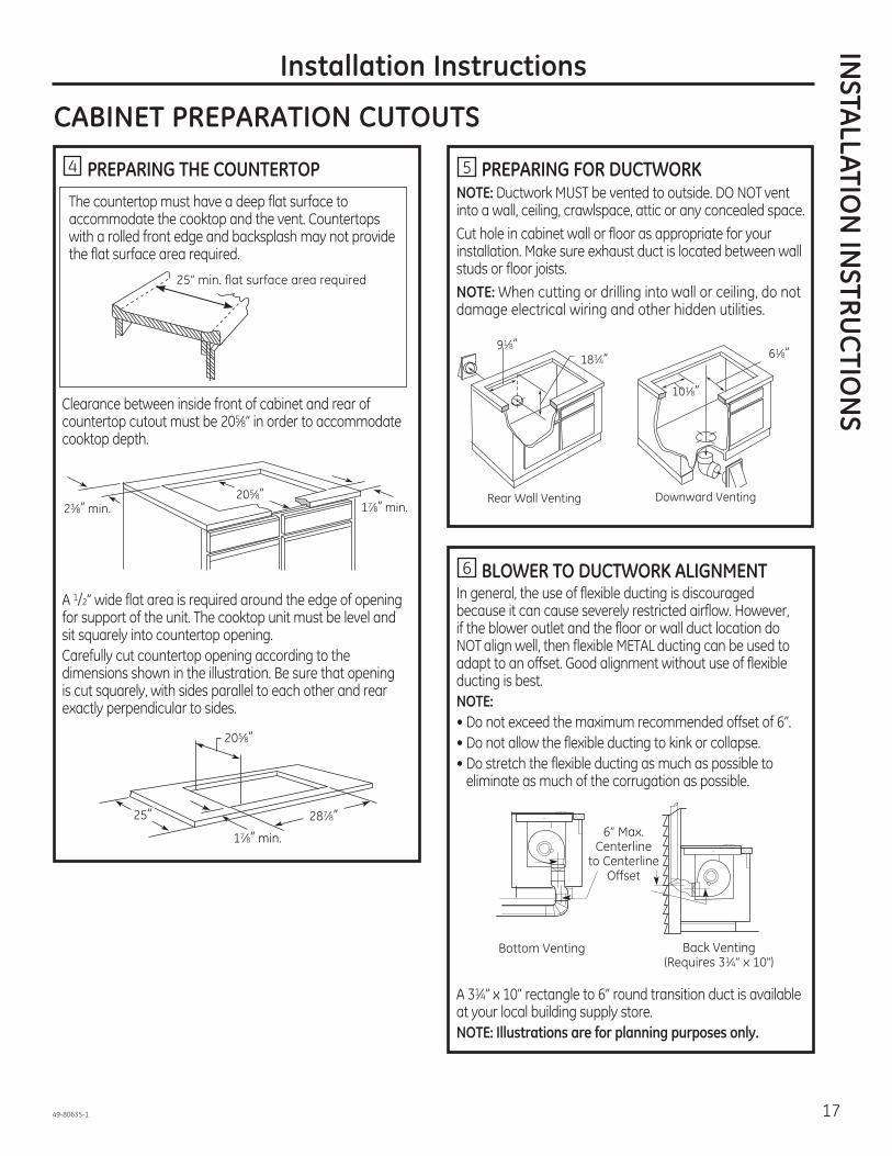
4 PREPARING THE COUNTERTOP The countertop must have a deep flat surface to
accommodate the cooktop and the vent. Countertops with a rolled front edge and backsplash may not provide the flat surface area required.
Clearance between inside front of cabinet and rear of countertop cutout must be 205 8” in order to accommodate cooktop depth.
A 1/2” wide flat area is required around the edge of opening for support of the unit. The cooktop unit must be level and sit squarely into countertop opening.Carefully cut countertop opening according to the dimensions shown in the illustration. Be sure that opening is cut squarely, with sides parallel to each other and rear exactly perpendicular to sides.
5 PREPARING FOR DUCTWORKNOTE: Ductwork MUST be vented to outside. DO NOT vent into a wall, ceiling, crawlspace, attic or any concealed space.Cut hole in cabinet wall or floor as appropriate for your installation. Make sure exhaust duct is located between wall studs or floor joists.NOTE: When cutting or drilling into wall or ceiling, do not damage electrical wiring and other hidden utilities.
6 BLOWER TO DUCTWORK ALIGNMENTIn general, the use of flexible ducting is discouraged because it can cause severely restricted airflow. However, if the blower outlet and the floor or wall duct location do NOT align well, then flexible METAL ducting can be used to adapt to an offset. Good alignment without use of flexible ducting is best.NOTE:• Do not exceed the maximum recommended offset of 6”.• Do not allow the flexible ducting to kink or collapse.• Do stretch the flexible ducting as much as possible to
eliminate as much of the corrugation as possible.
A 31 4” x 10” rectangle to 6” round transition duct is available at your local building supply store.NOTE: Illustrations are for planning purposes only.
25” min. flat surface area required
205 8”17 8” min.23 8” min.
205 8”
17 8” min.
25” 287 8”
91 8”183 4”
101 8”
61 8”
Rear Wall Venting Downward Venting
Back Venting (Requires 31 4” x 10")
Bottom Venting
6” Max. Centerline
to Centerline Offset

18 49-80635-1
INST
ALL
ATIO
N IN
STRU
CTI
ON
S Installation Instructions
DESIGN INFORMATION
7 PREPARE FOR DUCTWORKDetermine the best route for ductwork; it can be routed in a variety of ways depending on the kitchen layout.IMPORTANT: The downdraft air discharge outlet for this unit is
Typical duct arrangement countertop series.
To maximize the ventilation performance of the vent system:1. Minimize the duct run length and number of transitions
and elbows.2. Maintain a constant duct size.3. Seal all joints with duct tape to prevent any leaks.4. Do not use any type of flexible ducting.
If needed, install any make up (replacement) air system in accordance with local building code requirements. Visit GEAppliances.com for available makeup air solutions.
• Install ductwork so the piece of duct nearest the downdraft unit slots INTO the next piece of the duct. Secure the joints with self-tapping screws and apply duct tape around the joints to ensure an airtight seal.
Inside wall cabinet
Up inside wall to roof or overhang
Directly to outside
Between floor joists Through cabinet toe space
Peninsula or island
Peninsula
Outside wall cabinet
NOTE: PVC sewer pipe type PSM 12454-BSchedule 40 ASTM D1785.
Wall Cap ConcreteSlab
6″ (15 cm)Dia. PVC
Sewer Pipe
6″ (15 cm) Dia. MetalDuct
Pack tightly with gravelor sand completely
around pipe
3-1/4″ x 10″ Rectangular to 6″ Round Transition
6″ (15 cm) Dia. 90° Metal Elbow
6″ (15 cm) Dia. Metal Duct
16″ (40.6 cm) Max.
12″ (30 cm)
Min.
6″ (15 cm) Dia. PVC Coupling
6″ (15 cm) Dia. PVC Sewer Pipe Elbow
6″ (15 cm) Dia. PVC Sewer Pipe Elbow
6″ (15 cm) Dia. PVC
Sewer Pipe
6″ (15 cm)
Dia. PVC
Coupling30′-0″ (9.14 m) Max.
Optional duct arrangement under concrete slab.PVC duct should be used if installing under a poured concrete slab.
Duct TapeOver Seam and Screw
Screw
Air
Flow

49-80635-1 19
Installation Instructions
UNPACKING THE COOKTOP/INSTALLING THE GASKET
8 INSTALLING THE FOAM GASKETDo not install the cooktop into the countertop without installing the foam gasket as shown. It protects the bottom edge of the glass from the countertop and seals the cooktop against spills.Remove the cooktop along with its shipping pad from the shipping box. Remove the shipping block from the downdraft vent opening and place it under the shipping pad to provide level support.
CAUTION: GLASS IS FRAGILE. DO NOT BUMP EDGE OF GLASS DURING INSTALLATION.Locate the reflective tape and foam gasket tape included with your cooktop.
Peel off the white backing to install the foam gasket tape on the bottom side of the cooktop glass as shown.
Foam Gasket Installation Notes:• The foam gasket tape should be installed within 1/8” of
the edge of the glass. Do not stretch or twist the foam gasket tape.
CAUTION: Failure to install foam gasket tape greatly increases the potential of breaking the cooktop glass when installing, especially in Corian® or granite countertops.• Use care not to stretch the foam gasket tape while it is
installed or it will not stay in place.• Do not place foam gasket tape over the metal flanges.• Butt the foam gasket tape ends together at each corner
without overlapping.• Trim the foam gasket tape to length without stretching.• Mitre cut outside corners of foam gasket tape slightly if
necessary for appearance.
• Do not scratch the glass while cutting the foam gasket tape.
Center vent shipping block – place under the shipping pad to provide level support
Underside of Glass
Foam Gasket Tape
1 8” max. to Glass Edge
INSTA
LLATION
INSTRU
CTIO
NS

20 49-80635-1
INST
ALL
ATIO
N IN
STRU
CTI
ON
S Installation Instructions
INSTALLING THE COOKTOP
9 INSTALLING THE COOKTOP:
Lift the cooktop by the glass side edges as shown.NOTE: Do not use the glass top vent opening to lift or move the cooktop into position.
Lower the cooktop into the countertop opening, guiding it
countertop. Support from the underside and lower slowly.Carefully remove your fingers one corner at a time to lower the cooktop into position.NOTE: Do not use Silicone RTV or caulk to bond cooktop glass to countertop.Once the unit is placed in countertop; visually inspect the cooktop and counter, appearance or alignment concerns.
10 INSTALLING THE OPTIONAL INSTALLATION BRACKETS
NOTE: Check for glass flatness in Step 9 before installing optional installation brackets.
To order optional installation brackets/thumb screws, call the National Parts Center at 800.626.2002. Order two of each part: WB02X11331 Bracket
WB01X10353 ScrewTo install optional installation brackets:Remove 2 screws on both sides under cooktop.Align optional installation bracket under cooktop and reinstall screws through the slot in the bracket. Do this on both sides of the cooktop.Thread the thumb screw through the hole in the bracket and tighten to secure the cooktop to the countertop. Repeat on the other side.IMPORTANT: Turn thumb screw until it touches the bottom of the countertop. Do not overtighten.
CAUTION: DO NOT LIFT FROM
VENT OPENING. Optional installation bracket and thumbscrew (not included)
Cooktop Countertop
Screws supplied with cooktop
Thumbscrew

49-80635-1 21
Installation Instructions
INSTALLING THE COOKTOP
11 INSTALLING THE BLOWER PLENUM TO THE COOKTOP
Slide the plenum, with the blower opening on the left, into the opening in the bottom of the cooktop. Push up on the plenum until the stops on the plenum contact the bottom of the cooktop, and snap the plenum into place. (You may have to move the plenum back and forth to work it into place.)
Secure the plenum to the bottom of the cooktop, on each side, using the four (4) screws provided. Further secure the plenum to the cooktop, from the top side, using the two screws (2) provided.
12 INSTALLING THE BLOWER TO THE PLENUM
Orient the blower discharge opening to match the ductwork in Steps 6 and 7. Slide the four threaded studs on the side of the blower housing into the four holes on the side of the plenum.NOTE: See Step 13 for installing the transition duct to the blower. It may be easier to install the transition duct to the blower before installing the blower to the plenum.
From the vent opening in the top of the cooktop, fasten the blower assembly securely to the plenum with four (4) nuts.
Install 4 screws
Install 2 screws
4 Nuts (7/16” socket required)
INSTA
LLATION
INSTRU
CTIO
NS

22 49-80635-1
INST
ALL
ATIO
N IN
STRU
CTI
ON
S Installation Instructions
INSTALLING THE COOKTOP
• Connect the 5-pin plug on the blower assembly to the matching 5-pin receptacle on the bottom of the cooktop.
• Fold all wires into the electrical enclosure. Secure the enclosure with the screws removed earlier, making sure that no wires are trapped.
14 BLOWER ELECTRICAL CONNECTIONS• Loosen the two screws and remove and discard the sheet
metal strap covering the 5-pin connector on the cooktop bottom. Save the screws for reinstallation later.
13 ATTACHING A BLOWER TRANSITION DUCT
Use a blower transition duct for all downward duct installations to connect to 6” round standard ductwork. This 31 4” x 10” rectangle to 6” round transition duct is available at your local building supply store.
Install the transition duct to the blower outlet. Secure all joints with duct tape to assure an airtight seal.
15 CONNECTING THE DUCTWORKConnect the ductwork prepared in Steps 6 and 7 to the blower.
Remove screws and discard strap
5-pin connectors
5-pin connectors
Electrical enclosure
Flexible conduit
Screws
Screw (on other side)

49-80635-1 23
INSTA
LLATION
INSTRU
CTIO
NS
Installation Instructions
ELECTRICAL CONNECTIONS
ELECTRICAL REQUIREMENTS*Model # Voltage Frequency KWPP989 120/240V 60Hz 9.1KW 120/208V 60Hz 6.9KW* For reference only. Verify with product rating plate.
16 BEFORE MAKING ELECTRICAL CONNECTIONS
Note to Electrician: The power leads supplied with this appliance are UL-recognized for connection to large gauge household wiring. The insulation of these leads is rated at temperatures much higher than the temperature rating of household wiring. The current carrying capacity of a conductor is governed by the wire gauge and also the temperature rating of the insulation around the wire.
Aluminum Wiring – WARNING: IMPROPER CONNECTION OF ALUMINUM HOUSE WIRING TO THE COPPER LEADS CAN RESULT IN SERIOUS PROBLEMS.Attach copper wires to aluminum wiring using special connectors designed and UL-listed for joining copper to aluminum. Follow the connector manufacturer’s recommended procedure closely.Service Loop – Leave a loop in the wires to the cooktop so that the cooktop can be lifted 12 inches without having to disconnect the wiring.
Electrical installation kit JXCK89 may be ordered separately and includes all the parts necessary to connect the cooktop to typical rough-in wiring.
17 INSTALL 3/4” FLEXIBLE CONDUITRemove the screws holding the wire compartment cover and remove the cover.
Feed the power supply leads through the conduit; be sure to leave enough length to properly connect these leads to the cooktop power leads.Thread the leads through an anti-short bushing and firmly seat the bushing in the end of the conduit.Feed the leads through the hole in the wire compartment.As local codes permit purchase a listed conduit connector suitable for the size conduit. Insert the conduit through the connector and attach it to the cover. Allow enough slack to easily attach the wires to the cooktop.NOTE: Do not install the cooktop without a listed conduit connector. The conduit connector should be installed before reinstalling the wiring cover.When complete, reinstall the wire compartment cover.
Rating Plate
Power Supply Leads
Anti-Short Bushing Conduit
Bushing (Fully Seated)
Conduit Connector
Conduit Cover

24 49-80635-1
Installation Instructions
ELECTRICAL CONNECTIONS
18 MAKING ELECTRICAL CONNECTIONSEffective January 1, 1996, the National Electrical Code requires that new, but not existing, construction utilize a four-conductor connection to an electric range. When installing an electric range in new construction, follow the instructions in NEW CONSTRUCTION AND FOUR-CONDUCTOR BRANCH CIRCUIT CONNECTION.You must use a three-wire, single-phase AC 208Y/120 Volt or 240/120 Volt, 60 Hertz electrical system with separate ground. If you connect to aluminum wiring, properly installed connectors approved for use with aluminum wiring must be used.
New construction and four-conductor branch circuit connection• When installing in new construction, or• When installing in a mobile home, or• When local codes do not permit grounding through
neutral:
4-Conductor Branch CircuitWhen connecting the cooktop to a 4-conductor circuit, connect the red leads of the cooktop and the power supply to the branch circuit red lead; connect the black leads to each other. Connect the cooktop white lead to the power supply and branch circuit neutral leads, which are white or gray. Ground the unit by connecting the green conductor of the cooktop to the bare or green leads of the power supply and branch circuit (ground leads).
Three-conductor branch circuit connection• When installing in existing construction built prior to
January 1, 1996, and if permitted by local codes:
3-Conductor Branch CircuitWhen connecting cooktop to a 3-conductor circuit, connect the red leads of the cooktop and the power supply to the branch circuit red lead; connect the black leads to each other. Connect the green and white leads of the cooktop to the power supply and branch circuit neutral leads, which are white or gray.
INST
ALL
ATIO
N IN
STRU
CTI
ON
S

49-80635-1 25
INSTA
LLATION
INSTRU
CTIO
NS
Installation Instructions
FINAL ASSEMBLY
19 INSTALL DOWNDRAFT FILTER VENT GRILLE
Do not operate the vent without the filter in place.• Place the filter diagonally through the vent opening.
• Make sure it rests, at an angle, on the supports in the vent opening.
• Carefully place the vent grille onto the downdraft opening.
CHECK OPERATION OF DOWNDRAFT• Turn the vent fan speed control to HI, MED and LO to
make sure all speeds operate correctly.
Vent Filter
Vent Chamber

26 49-80635-1
Notes

49-80635-1 27
Notes

28 49-80635-1
Save time and money! Review the charts on the following pages first and you may not need to call for service.
Problem Possible Cause What To DoWater won’t boil
until the water begins to boil.Surface units will not maintain a rolling boil or cooking is slow
Improper cookware being used. Pan bottoms should be flat, fairly heavyweight and the same diameter as the surface unit selected.
Surface units do not work properly
A fuse in your home may be blown or the circuit breaker tripped.
Replace the fuse or reset the circuit breaker.
Cooktop controls improperly set.surface unit you are using.
Tiny scratches or metal marks (may appear as cracks) or abrasions on radiant cooktop glass surface
Incorrect cleaning methods being used.Cookware with rough bottoms being used or coarse particles (salt or sand) were between the cookware and the surface of the cooktop.
Tiny scratches are not removable but will become less visible in time as a result of cleaning.
Cookware has been slid across the cooktop surface.
Areas of discoloration or dark streaks on the cooktop
Improper cookware being used. Marks from aluminum and copper pans as well as mineral deposits from water or food can be removed with the cleaning cream.
Hot surface on a model with a light-colored cooktop.
This is normal. The surface may appear discolored when it is hot. This is temporary and will disappear as the glass cools.
Food spillovers not cleaned before next use.Incorrect cleaning methods being used.
Hot sugar mixtures or plastic melted to the surface
Hot cooktop came into contact with these substances.
section.Pitting (or indentation) of the cooktop
Hot sugar mixture spilled or plastic melted on the cooktop.
Cooktop making an audible sound
Cooktop is locked.
Frequent cycling off and on of surface units
Improper cookware being used.
Cooktop feels hot Improper cookware being used. The glass cooktop surface may seem hotter than
are absolutely flat.Control knob will not turn
Cooktop controls improperly set.
knob is in any other position, it can be turned without being pushed in.
Poor venting Clogged filter.House too airtight. Open a window slightly to provide fresh air source.Wall cap obstructed. Remove blockage from exterior wall cap.Wall cap damper door stuck.
movement or obstruction.Duct length exceeds recommended 100 equivalent foot maximum.
Reduce number of elbows to simplify duct run.
Troubleshooting tips ... Before you call for serviceTR
OU
BLES
HO
OTI
NG
TIP
S

49-80635-1 03-15 GE
Estu
fara
dian
te d
e ve
ntila
ción
des
cend
ente
(dow
ndra
ft)
Manual del propietario e instalación
PP9830
Escriba el modelo y los números de serie a continuación:
Modelo No: ___________________
Serie No: ______________________
Encuentre estos números en una etiqueta debajo de la estufa, en el lado de la cámara de ventilación.
GEAppliances.com
Información De Seguridad . . . . 2
Garantía . . . . . . . . . . . . . . . . . . . . . . . . . . 4
Asistencia / Piezas y Accesorios . . . . . . . . . . . . . 5
Uso de la placa de cocciónFunciones de la Placa de Cocción . . . . 6Quemadores . . . . . . . . . . . . . . . . . . . . . . . . 7Utensilio para Placa de Cocción para Vidrio Radiante . . . . . . . . . . . . . . . 9Para Mejores Resultados . . . . . . . . . . . . 9
Cuidado Y LimpiezaLimpieza de la Placa de Cocción . . . . 10Cómo Limpiar la Estufa de Vidrio. . . . 11
Instrucciones de Instalación . . 13
Consejos para la Solución de Problemas . . . . . . . . . . . . . . . . . 25

2 49-80635-1
GUARDE ESTAS INSTRUCCIONES
INFORMACIÓN IMPORTANTE DE SEGURIDADLEA TODAS LAS INSTRUCCIONES ANTES DE USAR
INFO
RMAC
IÓN
DE
SEG
URI
DA
D
Lea todas las instrucciones de seguridad antes de utilizar este producto. No seguir estas instrucciones puede generar un incendio, una descarga eléctrica, lesiones corporales o la muerte.
ADVERTENCIA
INSTRUCCIONES GENERALES DE SEGURIDAD
MANTENGA LOS MATERIALES INFLAMABLES ALEJADOS DE LA ESTUFA.
ADVERTENCIA
ADVERTENCIA
PRECAUCION: No almacene elementos de
la cocina para alcanzar elementos pueden resultar
o los elementos calentadores calientes. No utilice toallas u otras telas gruesas en lugar de una agarradera.
puerta del horno.
de res hasta alcanzar una temperatura interna de por
temperatura interna de por lo menos 180°F (82°C). La

49-80635-1 3GUARDE ESTAS INSTRUCCIONES
INFO
RMAC
IÓN
DE SEG
URID
AD
EN CASO DE INCENDIO, SIGA LOS SIGUIENTES PASOS PARA EVITAR LA PROPAGACIÓN DEL FUEGO:
INSTRUCCIONES DE SEGURIDAD DE LA ESTUFA RADIANTE
ADVERTENCIA
ADVERTENCIA
de incendios de espuma.
controlar la temperatura del aceite.
® ®

4 49-80635-1
¡Gracias! ... por su compra de un electrodoméstico de la Marca GEG
ARA
NTÍ
A
Garantía de la Superficie de Cocción Radiante de GEGEAppliances.com
Qué no cubrirá GE:
(reemplazo) de aire.
EXCLUSIÓN DE GARANTÍAS IMPLÍCITAS
hogar.
Garante: General Electric Company. Louisville, KY 40225
Garantías Extendidas:
Registre su Electrodoméstico:

49-80635-1 5
Piezas y Accesorioswww.GEApplianceParts.com www.GEAppliances.ca
o llame al 800.626.2002 800.661.1616
ASISTEN
CIA
/ PIEZAS Y ACC
ESORIO
S
Servicio Programado:
Piezas y Accesorios:
Estudio de Diseño de la Vida Real:
Contáctenos:
General Manager, Customer RelationsGE Appliances, Appliance Park Louisville, KY 40225
www.geappliances.com/service_and_support/
¿Desea realizar una consulta o necesita ayuda con su electrodoméstico?
Cómo Retirar la Película Protectora de Envío y la Cinta de Embalaje
electrodoméstico.
NOTA:No se puede retirar si se hornea con éste dentro.
Piezas
Suministros de Limpieza
®
®
®
®

6 49-80635-1
Es posible que las funciones y apariencias varíen con relación a su modelo a lo largo del manual.
Funciones de la Placa de CocciónU
SO D
E LA
PLA
CA
DE
COCC
IÓN
: Fun
cion
es d
e la
Pla
ca d
e Co
cció
n
1. Unidad de superficie posterior izquierda2. Unidad de superficie de puente3. Unidad de superficie frontal izquierda4. Parrilla de ventilación5. Filtro de ventilación (debajo de la parrilla de ventilación)6. Unidad de superficie posterior derecha7. Unidad de superficie doble8. Etiqueta con los números de modelo y serie (debajo de la
estufa, en el lado derecho de la cámara de ventilación)9. Control de la unidad de superficie posterior izquierda10. Control de la unidad de superficie frontal izquierda11. Luces indicadoras de que la superficie está caliente del lado
izquierdo (una por cada unidad de superficie)12. Control de velocidad del ventilador de ventilación13. Perilla de bloqueo de control14. Luces indicadoras de que la superficie está caliente del lado
derecho (una por cada unidad de superficie)15. Control de unidad de superficie doble16. Control de unidad de superficie posterior derecha17. Luz indicadora encendida de la unidad de superficie
Índice de características (las características y la apariencia podrían variar de acuerdo con su modelo)
4 51 6
3 7 8
2
9
13
17
12
11
10 15
16
14

49-80635-1 7
QuemadoresU
SO D
E LA PLAC
A D
E COCC
IÓN
: Quem
adores
Unidades de superficie radiantes
LO (Bajo) HI (Alto)de selecciones de calentamiento ilimitado. Con el interruptor
OFF (Apagado)
OFF (Apagado).
La luz indicadora de la unidad
ON(Encendido).
HOT
Acerca de las unidades de superficie radiantes
NOTA:
NOTA:Nunca cocine directamente sobre el vidrio. Siempre use piezas de cocina.
Siempre coloque la sartén en el centro de la unidad de superficie en la que está cocinando.
No deslice sartenes encima de la superficie de la estufa porque esto podría rasguñar el vidrio. El vidrio es resistente, pero no es a prueba de rasguños.
Cerciórese de girar el botón de control a apagado (OFF) cuando
termine de cocinar.
COCINE SOBRE LA SUPERFICIE
NO EN CENTRO
DESLICE

8 49-80635-1
Quemadores (Cont.)U
SO D
E LA
PLA
CA
DE
COCC
IÓN
: Que
mad
ores
Unidad de superficie doble
Unidad de superficie de puente
hacia
Los elementos de superficie se encienden y apagan
demasiado.
Limitador de temperatura
temperatura.
calentarse demasiado.
en ciclo apagado si:
Bloqueo de control de las unidades de superficie
LOCK (Bloqueo)
OFF (Apagado).
Cómo operar el sistema de ventilación
HI (Alto), MED (Medio) o LO(Bajo)
Selección de la unidad de superficie pequeña de 6”
Selección de la unidad de superficie grande de 9”
Quemador frontal y puente
Quemador frontal solamente

49-80635-1 9
Utensilio para Placa de Cocción para Vidrio Radiante
Para Mejores Resultados
Acero inoxidable:
Aluminio:
Base de cobre:
Esmalte de porcelana sobre hierro fundido:
Esmalte de porcelana sobre acero:No se recomienda
Vidrio-cerámico:No se recomienda
Cerámica:No se recomienda
Hierro fundido:
NOTA:
contacto adecuado.
USO
DE LA
PLACA
DE CO
CCIÓ
N: U
tensilio para Placa de Cocción para Vidrio Radiante / Para mejores resultados
Verifique que los recipientes tengan bases planas utilizando una regla.
No se recomiendan recipientes con bases redondeadas, curvadas, con rebordes o torceduras..
No coloque recipientes mojados sobre la estufa de vidrio.
No use woks con anillos de soporte sobre la estufa de vidrio.
Utilice woks de base plana sobre la estufa de vidrio.

10 49-80635-1
Limpieza de la Placa de CocciónC
UID
AD
O Y
LIM
PIEZ
A: L
impi
eza
de la
Pla
ca d
e Co
cció
n
Botones de control
de Off (Apagado)
de Off (Apagado)
Superficies de Acero Inoxidable (en algunos modelos)
Rejilla de ventilación
Cámara y filtro de ventilación
No opere la ventilación sin el filtro en su lugar.
No opere la ventilación sin el filtro en su lugar.
Remueva y reemplace el filtro diagonalmente a través de la abertura de ventilación.
Para ordenar filtros de reemplazo, lea las secciones de Asistencia / Piezas y Accesorios.
Cuando se encuentre reemplazando el filtro, cerciórese de que descanse, en un ángulo, en los soportes en la abertura de ventilación.
Cámara de ventilación
Filtro de ventilación
Área sombreada

49-80635-1 11
Residuos pegadosNOTA:
® en
® para
anterioridad.
®
Utilice un paño de limpieza CERAMA BRYTE® para estufas cerámicas.
CU
IDA
DO
Y LIMPIEZA
: Cómo Lim
piar la Estufa de VidrioCómo Limpiar la Estufa de VidrioLimpieza normal de uso diario
®
siga estos pasos:
®
®
®
®
NOTA:
Limpie la estufa después de cada derrame. Utilice el limpiador de estufas cerámicas CERAMA BRYTE®.
Residuos pegados rebeldes
®
®
El raspador de estufas cerámicas CERAMA BRYTE® y todos los insumos recomendados se encuentran disponibles en nuestro Centro de Repuestos. Lea las secciones de Asistencia / Piezas y Accesorios.NOTA: No utilice hojas desafiladas o dañadas.

12 49-80635-1
CU
IDA
DO
Y L
IMPI
EZA
: Cóm
o Li
mpi
ar la
Est
ufa
de V
idrio Cómo Limpiar la Estufa de Vidrio
Daños por derrames azucarados y plástico derretidoa fin de evitar daños permanentes sobre la superficie de
vidrio.
sartenes calientes.
®) para desplazar el NOTA:
Marcas metálicas y rasguñaduras
® con la almohadilla ®.
ADVERTENCIA: Con mucho cuidado
49-80635-1 13
Instrucciones Estufa radiante de ventilación descendente
de Instalación PP9830
“Si tiene alguna pregunta, llame al 800.GE.CARES o visite nuestro sitio Web en: GEAppliances.com”
INSTRU
CCIO
NES D
E INSTA
LACIÓ
N
ANTES DE COMENZARLea estas instrucciones completa y cuidadosamente.
• IMPORTANTE – Guarde estas instrucciones para ser usadas por el inspector local.
• IMPORTANTE – Observe todos los códigos y ordenanzas aplicables.
• Nota al instalador – Cerciórese de dejar estas instrucciones con el Consumidor.
• Nota al consumidor – Guarde estas instrucciones para referencia futura.
• A menos que posea un gran nivel de conocimiento sobre la instalación de este producto, contrate a un instalador profesional.
• La instalación apropiada es la responsabilidad del instalador.• Si este producto falla por una instalación inapropiada, la
Garantía no cubrirá este producto.
ADVERTENCIA – Antes de comenzar la instalación, desconecte el interruptor de suministro eléctrico en el panel de servicio y cierre el mecanismo de seguridad para evitar que alguien lo conecte accidentalmente. Cuando no exista un dispositivo de cierre de seguridad, amarre un aviso visible, como una etiqueta al panel de servicio haciendo la advertencia.
ADVERTENCIA – PARA REDUCIR EL RIESGO DE INCENDIOS, SOLAMENTE USE CONDUCTOS METÁLICOS.
INSTRUCCIONES IMPORTANTES DE SEGURIDAD
ADVERTENCIA – PARA REDUCIR EL RIESGO DE INCENDIOS, DESCARGAS ELÉCTRICAS O LESIONES PERSONALES, OBSERVE LO SIGUIENTE: A El trabajo de instalación y el alambrado eléctrico debe
hacerlo una persona(s) calificada conforme a todos los códigos y estándares aplicables, incluyendo una construcción aprobada por el inspector de incendios.
B Suficiente aire es necesario para una combustión apropiada y para deshacerse de los gases a través de una salida de humo (chimenea) de equipos que queman combustibles para prevenir retroalimentación. Siga las recomendaciones del fabricante del equipo de calentamiento y los estándares de seguridad tales como los publicados por la Asociación nacional de protección de incendios (NFPA), y la Sociedad americana de ingenieros de calefacción, acondicionadores de aire y refrigeración (ASHRAE), y los códigos de las autoridades locales.
C Cuando se encuentre cortando o taladrando en la pared o en el techo, no dañe los alambrados eléctricos u otras utilidades escondidas.
D Los ventiladores conectados a conductos deben siempre estar ventilados hacia el exterior.
• La unidad debe estar conectada a tierra apropiadamente.
RANGOS DEL SOPLADOR DE ESCAPEADVERTENCIA DE SEGURIDAD DEL SOPLADOR DE ESCAPEEs necesario contar con suficiente cantidad de aire para una combustión y salida de gases adecuadas a través del conducto (chimenea) del equipo de consumo de combustible, a fin de evitar descargas. Siga las pautas del fabricante del equipo de calefacción y los estándares de seguridad, tales como aquellos publicados por la Asociación Nacional de Protección contra Incendios (National Fire Protection Association, NFPA), la Sociedad Estadounidense para la Calefacción (American Society for Heating), los Ingenieros de Refrigeración y Acondicionadores de Aire (Refrigeration and Air Conditioning Engineers, ASHRAE) y las autoridades de los códigos locales. Cuando corresponda, instale un sistema de reposición (reemplazo) de aire de acuerdo con los requisitos del código local de construcción. Para acceder a soluciones relacionadas con la reposición de aire, visite GEAppliances.com.

14 49-80635-1
INST
RUCC
ION
ES D
E IN
STA
LAC
IÓN Instrucciones de Instalación
DESEMPACANDO SU ESTUFA
Rejilla de ventilación
Crema de limpiezaEsponja de restriegue
o raspador (en algunos modelos)
Tornillos de plancha metálica (9) (8-18 x 3/8”)
Cinta de junta de espuma (rollo de 9 pies)
Ensambladura del soplador y tuercas de montaje (4)
de cierre pegadas)
Pleno del soplador
Filtro del ventilador
PRECAUCIÓN: NO LEVANTE POR LA ABERTURA DE VENTILACIÓN O CHOQUE EL VIDRIO.
Asegúrese que todos los materiales de empaque y cintas se hayan retirado. Esto incluye cintas sobre las perillas de control (si corresponde), cinta adhesiva, cintas de ajuste, cartón y plástico protector. Si estos materiales no se retiran se puede producir como resultado un daño sobre el electrodoméstico, una vez que el mismo fue encendido y las superficies se calientan.
PRECAUCIÓN: EL VIDRIO ES FRÁGIL.NO CHOQUE LA ESQUINAS DEL VIDRIO DURANTE LA INSTALACIÓN.

49-80635-1 15
INSTRU
CCIO
NES D
E INSTA
LACIÓ
NInstrucciones de Instalación
PREPARACIÓN
ESTUFA DE 30” (DIMENSIONES PARA REFERENCIA SOLAMENTE)La unidad se muestra totalmente ensamblada.
La unidad debe tener ventilación hacia el exterior!
HERRAMIENTAS QUE NECESITARÁ• Guantes de protección contra cortes• Sierra• Destornillador plano• Alicates de electricista• Cinta adhesiva de conductos• Cinta métrica o escala• Escuadra de carpintero• Llave de 7/16" o juego de cubos• Taladradora y broca• Tornillos para hojas metálicas• Caja de unión*• Conducto flexible de 3/4"*• Cable eléctrico de acuerdo con los códigos locales*• Tuerca se alambre*• Conductos * NOTa: El Kit de instalación eléctrica JXCK89 puede ordenarse por separado e incluye todas las partes necesarias para conectar la estufa a un alambrado típico.
REQUISITOS ELÉCTRICOSEste electrodoméstico debe suplirse con el voltaje y la frecuencia apropiados, conforme se indica en estas Instrucciones de Instalación, y debe ser conectado a un ramo eléctrico conectado apropiadamente a tierra, protegido por un interruptor de circuito de 40 amperios o fusibles de dilatación de tiempo. Todas las conexiones de alambres deben hacerse de acuerdo con los códigos locales y deben estar apropiadamente aisladas. Póngase en contacto con la compañía de utilidades local para los códigos eléctricos y ordenanzas de su gobierno. En la ausencia de códigos eléctricos locales, el National Electrical Code, ANSI/NFPA No. 70 – en su más reciente edición, que gobierna la instalación de estufas eléctricas, deben seguirse. Usted puede obtener una copia del National Electrical Code escribiendo a:National Fire Protection Association Batterymarch Park Quincy, MA 02260Efectivo el 1 de enero de 1996, el National Electrical Code requiere que las construcciones nuevas, pero no ya existentes, utilicen conexiones de cuatro conductores para estufas eléctricos. Cuando se encuentre instalando una estufa eléctrica en una construcción nueva, siga las instrucciones en CONSTRUCCIÓN NUEVA Y CONEXIÓN DE RAMAL DE CIRCUITO DE CUATRO CONDUCTORES.Usted debe usar un sistema eléctrico de cables de tres alambres, de fase sencilla AC 208Y/120 voltios o 240/120 voltios, 60 Hertz con conexión a tierra por separado. Si usted conecta a alambres de aluminio, debe usar conectadoras aprobados para el uso con alambrado de aluminio.
PRECAUCIÓN: PARA SU SEGURIDAD PERSONAL, REMUEVA EL FUSIBLE DE LA CASA O EL INTERRUPTOR DE CIRCUITO ANTES DE COMENZAR LA INSTALACIÓN.
201 2”
22”
283 4”
217 8”(2115 16” SS)
2923 32”(2913 16” SS)
23 16”(21 4” SS)

16 49-80635-1
INST
RUCC
ION
ES D
E IN
STA
LAC
IÓN Instrucciones de Instalación
PREPARACIÓN DEL GABINETE
1 PREPARACIÓN PARA LA INSTALACIÓNPosición de su estufaLa estufa está diseñada para lucir mejor cuando está centrada en un gabinete de por lo menos 30" de ancho. La ventanilla de escape debajo de la estufa debe estar localizada entre los bajantes de la pared o entre las vigas del piso de forma que el trabajo de tubos pueda ser instalado apropiadamente. Por lo menos 6" se deben dejar entre los extremos laterales de la estufa y las paredes adyacentes.
Evite colocar gabinetes encima de la unidad, si es posible, para reducir los peligros causados por tener que intentar alcanzar unidades de superficie calentadas. Si los gabinetes están colocados encima de la estufa, los riesgos se pueden reducir instalando una capucha de estufa que proyecte horizontalmente un mínimo de 5 pulgadas más allá del fondo de los gabinetes.Si se usan gabineterías encima de la estufa, deje una tolerancia mínima de 30" entre la superficie de cocina y el fondo de cualquier gabinete no protegido. Si la tolerancia entre la estufa y la gabinetería es menor de 30", el gabinete debe protegerse con una plancha retardante de llamas de por lo menos 1/4" de grueso, cubierta con una plancha metálica de acero calibre 28 o con una pancha de cobre de 0.020". La tolerancia entre la estufa y la gabinetería protegida NUNCA DEBE SER MENOR DE 24". EEXCEPCIÓN: La instalación de un horno de microondas especificado o de un electrodoméstico de cocina sobre una estufa debe conformarse a las instrucciones de instalación empacadas con ese electrodoméstico. 15" mínimas deben dejarse a partir de cada lado de extremo de la estufa hasta el fondo de cualquier gabinete no directamente colocado sobre la estufa. Si la tolerancia es menor de 15", los gabinetes adyacentes deben ser de por lo menos 6" desde el lado extremo de la estufa.
3 PREPARACIÓN RÁPIDA DE UNA CAJA DE UNIÓN
PRECAUCIÓN: PARA SEGURIDAD PERSONAL, REMUEVA EL FUSIBLE DE LA CASA O ABRA EL INTERRUPTOR DE CIRCUITO ANTES DE PREPARAR LA CAJA DE UNIÓN.Instale una caja de unión aprobada dentro del área sombrada en el diagrama que se muestra en la ilustración.
gabinete superior. Pase los conductores desde el alambrado de la residencia hasta la caja de unión de acuerdo con los códigos eléctricos.
2 PREPARACIÓN DEL GABINETE DE LA BASEEsta estufa está diseñada para ajustar fácilmente en una variedad de gabinetes. Sin embargo, algunos gabinetes podrían requerir modificaciones. Preparando un gabinete que ajuste contra la paredEn algunos gabinetes, los lados podrían necesitar ser
las abrazaderas de las esquinas removidas para acomodar la unidad.En gabinetes europeos sin forma de 75 cm y 90 cm, el panel
acomodar la unidad. Preparando un gabinete tipo península o tipo islaEn gabinetes tipo península o isla, los lados podrían necesitar ser rebajados o cortados, y las abrazaderas de las esquinas removidas para acomodar la unidad.
La profundidad
del área elevada de
los gabinetes debe ser de un máximo
de 13"
Tolerancia mínima de 6" a
partir del corte hasta
los lados de las paredes.
Tolerancia mínima de 30" a partir de la encimera hasta
la superficie elevada
no protegida.
Altura mínima de 15" desde la encimera hasta el gabinete más cercano en cualquiera de los
lados de la unidad.
11 2" min.
Aproximadamente 53 4"
Para gabinetes europeos
aprox. 53 4"
16"
9"4"
20"
101 2"
C L
49-80635-1 17
INSTRU
CCIO
NES D
E INSTA
LACIÓ
NInstrucciones de Instalación
CORTES DE PREPARACIÓN DEL GABINETE
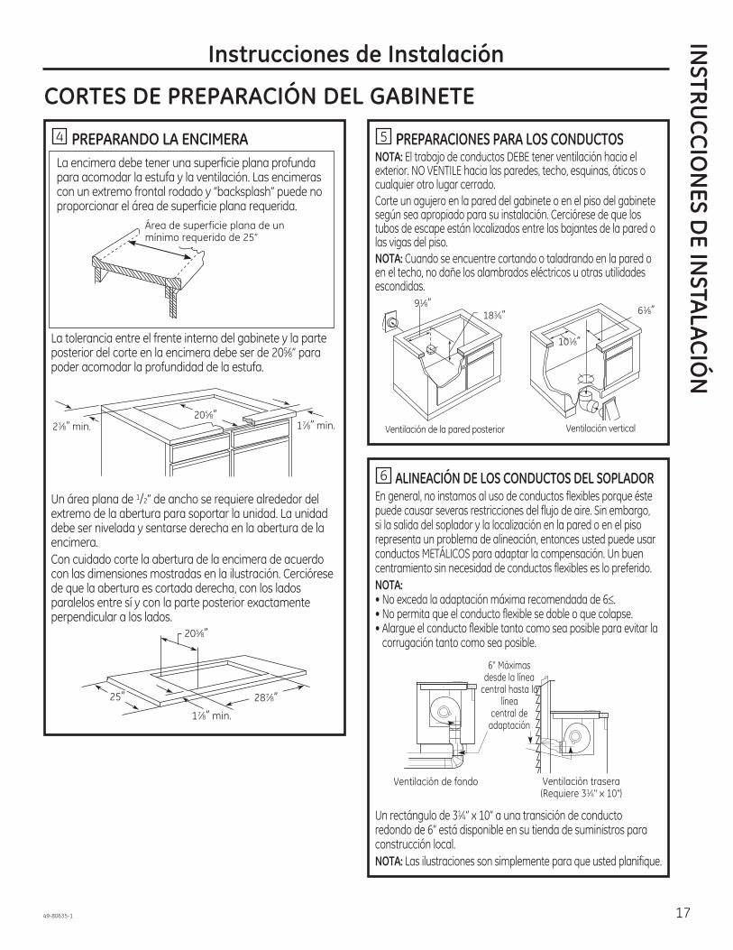
4 PREPARANDO LA ENCIMERA La encimera debe tener una superficie plana profunda
para acomodar la estufa y la ventilación. Las encimeras con un extremo frontal rodado y “backsplash” puede no proporcionar el área de superficie plana requerida.
La tolerancia entre el frente interno del gabinete y la parte posterior del corte en la encimera debe ser de 205 8” para poder acomodar la profundidad de la estufa.
Un área plana de 1/2” de ancho se requiere alrededor del extremo de la abertura para soportar la unidad. La unidad debe ser nivelada y sentarse derecha en la abertura de la encimera. Con cuidado corte la abertura de la encimera de acuerdo con las dimensiones mostradas en la ilustración. Cerciórese de que la abertura es cortada derecha, con los lados paralelos entre sí y con la parte posterior exactamente perpendicular a los lados.
5 PREPARACIONES PARA LOS CONDUCTOSNOTA: El trabajo de conductos DEBE tener ventilación hacia el exterior. NO VENTILE hacia las paredes, techo, esquinas, áticos o cualquier otro lugar cerrado. Corte un agujero en la pared del gabinete o en el piso del gabinete según sea apropiado para su instalación. Cerciórese de que los tubos de escape están localizados entre los bajantes de la pared o las vigas del piso.NOTA: Cuando se encuentre cortando o taladrando en la pared o en el techo, no dañe los alambrados eléctricos u otras utilidades escondidas.
6 ALINEACIÓN DE LOS CONDUCTOS DEL SOPLADOREn general, no instamos al uso de conductos flexibles porque éste puede causar severas restricciones del flujo de aire. Sin embargo, si la salida del soplador y la localización en la pared o en el piso representa un problema de alineación, entonces usted puede usar conductos METÁLICOS para adaptar la compensación. Un buen centramiento sin necesidad de conductos flexibles es lo preferido.NOTA:• No exceda la adaptación máxima recomendada de 6 .• No permita que el conducto flexible se doble o que colapse. • Alargue el conducto flexible tanto como sea posible para evitar la
corrugación tanto como sea posible.
Un rectángulo de 31 4” x 10” a una transición de conducto redondo de 6” está disponible en su tienda de suministros para construcción local.NOTA: Las ilustraciones son simplemente para que usted planifique.
Área de superficie plana de un mínimo requerido de 25”
205 8”17 8” min.23 8” min.
205 8”
17 8” min.
25” 287 8”
91 8”183 4”
101 8”
61 8”
Ventilación de la pared posterior Ventilación vertical
Ventilación trasera (Requiere 31 4" x 10")
Ventilación de fondo
6" Máximas desde la línea
central hasta la línea
central de adaptación

18 49-80635-1
INST
RUCC
ION
ES D
E IN
STA
LAC
IÓN Instrucciones de Instalación
INFORMACIÓN SOBRE EL DISEÑO
7 PREPARACIÓN DEL CONDUCTODetermine el mejor recorrido para el conducto; el mismo puede ser conducido de diferentes formas dependiendo del esquema de la cocina.IMPORTANTE: La salida de la descarga de aire descendente para esta unidad es rectangular, y con una medida de 3 1/4” x 10”. Planifique el recorrido de forma consecuente.Serie de mesadas con distribución típica de tuberías.A fin de maximizar el rendimiento de la ventilación del sistema de ventilación:1. Minimice la longitud del conducto y el número de
transiciones y codos.2. Mantenga un tamaño de tubería constante.3. Selle todas las juntas con cinta para conductos a fin de
evitar pérdidas.4. No utilice tuberías flexibles de ningún tipo.
De ser necesario, instale un sistema de reposición (reemplazo) de aire de acuerdo con los requisitos del código local de construcción. Para acceder a soluciones relacionadas con la reposición de aire, visite GEAppliances.com.
• Instale la tubería de modo que el trozo de conducto más cercano a la unidad descendente encaje DENTRO DE la siguiente pieza del conducto. Asegure las uniones con tornillos autorroscantes y coloque cinta para conductos alrededor de las uniones, a fin de sellar la salida de aire.
Pared interna del gabinete
Pared interna hacia arriba hasta el techo o parte saliente
Directamente hacia el exterior
Entre vigas del piso A través del espacio de las patas del gabinete
Península o isla
Península
Pared externa del gabinete
Arreglo opcional del conducto bajo una losa de concreto Se deberá usar un conducto de PVC si se instalará bajo una losa de concreto.
NOTA: Tubería de PVC tipo cloaca PSM 12454-BLista 40 ASTM D1785.
Tapa dePared Losa de
Concreto
Tubería paraCloaca dePVC de 6”
(15 cm.) de Diá.
Conducto Metálico de6” (15 cm.) de Diá.
Embale de forma bienajustada con grava o arena
completamentealrededor de la tubería.
Transición Rectangular de3 ¼” x 10” a Circular de 6”
Codo Metálicode 90º de 6”(15 cm.) de Diá.
6” (15 cm.) Diá.Conducto Metálico
16”(40.6 cm.)de Máx.
12”(30 cm.)
Mín.
Unión dePVC de 6”(15 cm.) Diá.
Codo para Tuberíade Cloaca de PVCde 6” (15 cm.) de Diá.
Codo para Tuberíade Cloaca de6” (15 cm.) de Diá.
Tubería deCloaca
de PVC de6” (15 cm.)
de Diá.
Unión dePVC de 6”
(15 cm) de Diá.
30’-0” (9.14 m.) Max.
Cinta para Conducto sobrela Unión y el Tornillo
Tornillo
Aire
Flujo

49-80635-1 19
Instrucciones de Instalación
CÓMO DESEMPACAR LA ESTUFA / INSTALAR LA JUNTA
8 CÓMO INSTALAR LA JUNTA DE ESPUMANo instale la estufa en la encimera sin haber instalado la junta de espuma como se muestra. Esta protege el extremo inferior del vidrio de la encimera y sella la estufa contra derrames.Remueva la estufa junto a sus almohadillas de empaque de la caja de envío. Remueva el bloque de envío de la abertura de ventilación descendente (downdraft) y colóquela debajo de la almohadilla de envío para proporcionar apoyo de nivel.
PRECAUCIÓN: EL VIDRIO ES FRÁGIL. NO GOLPEE LOS EXTREMOS DEL VIDRIO DURANTE LA INSTALACIÓN. Localice cinta reflectante y cinta de junta de espuma incluida con su estufa.
Pele la parte posterior blanca para instalar la cinta de la junta de espuma en el lado del fondo del vidrio de la estufa como se muestra.
Notas sobre la instalación de la junta de espuma:• La cinta de junta de espuma debería ser instalada dentro
de 1/8” del extremo del vidrio. No alargue o doble la cinta de junta de espuma.
PRECAUCIÓN: No instalar la cinta de junta de espuma aumenta el potencia de que el vidrio de la estufa se rompa cuando se esté instalando, especialmente en encimeras Corian® o de granito. • Use cuidado extremo de no alargar la cinta de junta de
espuma mientras la instala o no permanecerá en su lugar.• No coloque la cinta de junta de espuma sobre los bordes
metálicos.• Empalme los extremos de la cinta de junta de espuma en
cada esquina sin que una quede encima de la otra.• Cubra todo el marco con la cinta de junta de espuma sin
alargarla.• Corte las esquinas externas de la cinta de junta de espuma
ligeramente si fuera necesario para que luzca bien.
• No rasguñe el vidrio mientras corta la cinta de junta de espuma.
Centre el bloque de envío de la ventilación debajo de la almohadilla de envío para proporcionar apoyo de nivel.
Lado inferior del vidrio
Cinta de junta de espuma
1 8 máximo al extremo del vidrio
INSTRU
CCIO
NES D
E INSTA
LACIÓ
N

20 49-80635-1
INST
RUCC
ION
ES D
E IN
STA
LAC
IÓN
CÓMO INSTALAR LA ESTUFA
9 CÓMO INSTALAR LA ESTUFA
Levante la estufa por los extremos del lado del vidrio como se muestra.NOTA: No use la abertura de ventilación para levantar o
mover la estufa de posición.Baje la estufa hacia la abertura en la encimera, guiándola
se caiga sobre la encimera. Apoye desde el lado inferior y baje con cuidado.Cuidadosamente remueva sus dedos de una esquina a la vez para bajar la estufa hasta su posición. NOTA: No use RTV de silicona o masilla para unir el vidrio de la estufa a la encimera.Una vez ubicada la unidad en la mesada, inspeccione visualmente el aspecto o la alineación de la superficie de cocción y la mesada.
10 CÓMO COLOCAR LOS SOPORTES DE INSTALACIÓN OPCIONALES
NOTA: Verifique que el vidrio esté plano en el paso 9 antes de colocar los soportes de instalación opcionales.
Para solicitar soportes de instalación opcionales/tornillos de apriete, llame al Centro Nacional de Piezas al 800.626.2002.Solicite dos de cada pieza: WB02X11331 Soporte
WB01X10353 TornilloPara colocar soportes de instalación opcionales:Quite los 2 tornillos a ambos lados bajo la estufa. Alinee el soporte de instalación opcional bajo la estufa y reinstale los tornillos a través de la ranura del soporte. Haga esto en ambos lados de la estufa. Introduzca el tornillo de apriete a través del orificio del soporte y ajuste para fijar la estufa al mostrador de encimera. Repita en el otro lado.IMPORTANTE: Gire el tornillo de apriete hasta que toque la parte inferior de la estufa. No ajuste de más.
Instrucciones de Instalación
PRECAUCIÓN: NO LEVANTE POR LA ABERTURA DE
VENTILACIÓN. Soporte de instalación opcional y tornillo de apriete manual (no incluido)
Estufa Mostrador de encimera
Tornillos provistos con la estufa
Tornillo de apriete manual

49-80635-1 21
Instrucciones de Instalación
CÓMO INSTALAR LA ESTUFA
11 CÓMO INSTALAR LA CÁMARA DEL SOPLADOR DE LA ESTUFA
Deslice la cámara, con la abertura del soplador del lado izquierdo, en la abertura en el fondo de la estufa. Empuje la cámara hasta que se detenga cuando la cámara haga contacto con el fondo de la estufa, y la cámara encaje en su lugar. (Es posible que usted tenga que mover la cámara hacia adelante y hacia atrás para encontrar su lugar exacto.)
Asegure la cámara al fondo de la estufa, en cada lado, usando los cuatro (4) tornillos proporcionados. Luego asegure la cámara a la estufa, a partir del lado superior, usando los dos (2) tornillos proporcionados.
12 CÓMO INSTALAR LA CÁMARA DEL SOPLADOR
Oriente la abertura de descarga del soplador hasta que iguale el conducto en los Pasos 6 y 7. Deslice las cuatro tachuelas roscadas en el lado del alojamiento del soplador en los cuatro agujeros en el lado de la cámara. NOTA: Ver el Paso 13 para la instalación del conducto de transición del soplador. Es posible que sea más fácil instalar el conducto de transición al soplador antes de instalar el soplador a la cámara.
A partir de la abertura de ventilación en la parte superior de la estufa, apriete la ensambladura del soplador de manera firme a la cámara con cuatro (4) tuercas.
Instale 4 tornillos
Instale 2 tornillos
4 tuercas (se necesita un cubo de tuercas de 7/16”)
INSTRU
CCIO
NES D
E INSTA
LACIÓ
N
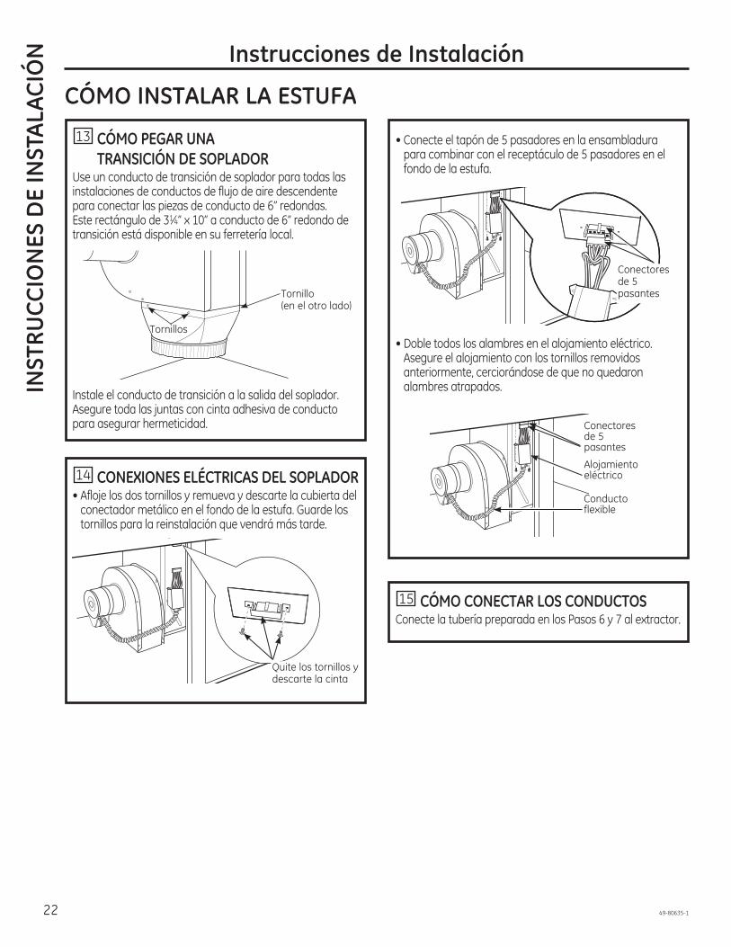
22 49-80635-1
INST
RUCC
ION
ES D
E IN
STA
LAC
IÓN
• Conecte el tapón de 5 pasadores en la ensambladura para combinar con el receptáculo de 5 pasadores en el fondo de la estufa.
• Doble todos los alambres en el alojamiento eléctrico. Asegure el alojamiento con los tornillos removidos anteriormente, cerciorándose de que no quedaron alambres atrapados.
14 CONEXIONES ELÉCTRICAS DEL SOPLADOR• Afloje los dos tornillos y remueva y descarte la cubierta del
conectador metálico en el fondo de la estufa. Guarde los tornillos para la reinstalación que vendrá más tarde.
15 CÓMO CONECTAR LOS CONDUCTOSConecte la tubería preparada en los Pasos 6 y 7 al extractor.
Instrucciones de Instalación
Quite los tornillos y descarte la cinta
Conectores de 5 pasantes
Conectores de 5 pasantes
Alojamiento eléctrico
Conducto flexible
CÓMO INSTALAR LA ESTUFA
13 CÓMO PEGAR UNA TRANSICIÓN DE SOPLADOR
Use un conducto de transición de soplador para todas las instalaciones de conductos de flujo de aire descendente para conectar las piezas de conducto de 6” redondas. Este rectángulo de 31 4” x 10” a conducto de 6” redondo de transición está disponible en su ferretería local.
Instale el conducto de transición a la salida del soplador. Asegure toda las juntas con cinta adhesiva de conducto para asegurar hermeticidad.
Tornillos
Tornillo (en el otro lado)

49-80635-1 23
Instrucciones de InstalaciónIN
STRUCC
ION
ES DE IN
STALAC
IÓN
CONEXIONES ELÉCTRICAS
REQUISITOS ELÉCTRICOS*# Modelo Voltaje Frecuencia KWPP989 120/240V 60Hz 9.1KW 120/208V 60Hz 6.9KW* Para referencia solamente. Verifique con la plato de especificación del producto.
16 ANTES DE HACER CONEXIONES ELÉCTRICAS
Nota al electricista: Los conductores proporcionados con este electrodoméstico son reconocidos por la UL para conexiones eléctricas residenciales de calibres altos. El aislamiento de estos conductores es considerado a temperaturas mucho mayores que las esperadas en residencias. La capacidad de carga actual de un conductor es determinado por el calibre del cable y también por la temperatura considerada del aislamiento alrededor del cable.
Alambre de aluminio – ADVERTENCIA: UNA CONEXIÓN DEL ALAMBRE DE ALUMINIO RESIDENCIAL INAPROPIADA A CONDUCTORES DE COBRE PUEDE RESULTAR EN PROBLEMAS SERIOS.Una los alambres de aluminio y los alambres de cobre usando conectadores especialmente diseñados y reconocidos por UL para unir cobre y aluminio. Siga el procedimiento recomendado por el fabricante de los conectadores muy de cerca. Onda de servicio – Deje una onda en el alambre de la estufa de forma tal que la estufa pueda ser levantada 12 pulgadas sin tener que desconectarse del alambrado.
El Kit de instalación eléctrica JXCK89 puede ordenarse por separado e incluye todas las partes necesarias para conectar la estufa a un alambrado típico.
17 INSTALE UN CONDUCTO FLEXIBLE DE 3/4" Remueva los tornillos que sostienen la cubierta del compartimiento del alambre y remueva la cubierta.
Alimente los conductores para el suministro eléctrico a través del conducto; cerciórese de dejar suficiente longitud para conectar apropiadamente estos conductores a los conductores eléctricos de la estufa. Envuelva los conductores a través del bushing o cojinete anti-cortocircuitos y asiente firmemente el bushing en el extremo del conducto. Alimente los conductores a través del agujero en el compartimiento de alambre. Conforme lo permitan los códigos locales, compre un conectador de conducto apropiado para el tamaño del conducto. Inserte el conducto a través del conectador y péguelo a la cubierta. Deje un huelgo suficiente para poder pegar los cables fácilmente con los cables de la estufa. Nota: No Instale la estufa sin un conectador de conducto certificado. El conectador de conducto debería instalarse antes de reinstalar la cubierta de cables. Cuando haya completado el proceso, reinstale la cubierta del compartimiento de los cables.
Plato de especificación
Conductores del suministro
eléctricoBushing anti-cortocircuito
Conducto
Bushing (asentado completamente)
Conectador de conducto
Conducto Cubierta
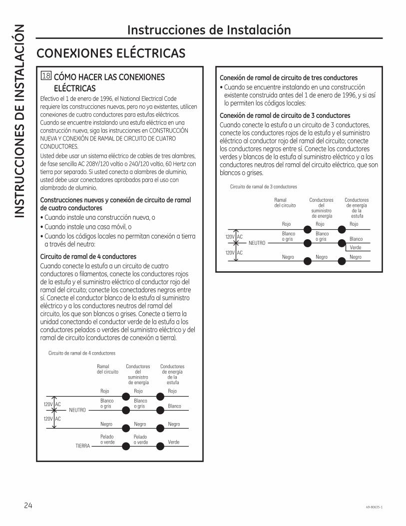
24 49-80635-1
Instrucciones de InstalaciónIN
STRU
CCIO
NES
DE
INST
ALA
CIÓ
N
CONEXIONES ELÉCTRICAS
18 CÓMO HACER LAS CONEXIONES ELÉCTRICAS
Efectivo el 1 de enero de 1996, el National Electrical Code requiere las construcciones nuevas, pero no ya existentes, utilicen conexiones de cuatro conductores para estufas eléctricos. Cuando se encuentre instalando una estufa eléctrica en una construcción nueva, siga las instrucciones en CONSTRUCCIÓN NUEVA Y CONEXIÓN DE RAMAL DE CIRCUITO DE CUATRO CONDUCTORES.Usted debe usar un sistema eléctrico de cables de tres alambres, de fase sencilla AC 208Y/120 voltio o 240/120 voltio, 60 Hertz con tierra por separado. Si usted conecta a alambres de aluminio, usted debe usar conectadores aprobados para el uso con alambrado de aluminio.
Construcciones nuevas y conexión de circuito de ramal de cuatro conductores• Cuando instale una construcción nueva, o• Cuando instale una casa móvil, o • Cuando los códigos locales no permitan conexión a tierra
a través del neutro:
Circuito de ramal de 4 conductoresCuando conecte la estufa a un circuito de cuatro conductores o filamentos, conecte los conductores rojos de la estufa y el suministro eléctrico al conductor rojo del ramal del circuito; conecte los conectadores negros entre sí. Conecte el conductor blanco de la estufa al suministro eléctrico y a los conductores neutros del ramal del circuito, los que son blancos o grises. Conecte a tierra la unidad conectando el conductor verde de la estufa a los conductores pelados o verdes del suministro eléctrico y del ramal de circuito (conductores de conexión a tierra).
Conexión de ramal de circuito de tres conductores• Cuando se encuentre instalando en una construcción
existente construida antes del 1 de enero de 1996, y si así lo permiten los códigos locales:
Conexión de ramal de circuito de 3 conductoresCuando conecte la estufa a un circuito de 3 conductores, conecte los conductores rojos de la estufa y el suministro eléctrico al conductor rojo del ramal del circuito; conecte los conductores negros entre sí. Conecte los conductores verdes y blancos de la estufa al suministro eléctrico y a los conductores neutros del ramal del circuito eléctrico, que son blancos o grises.
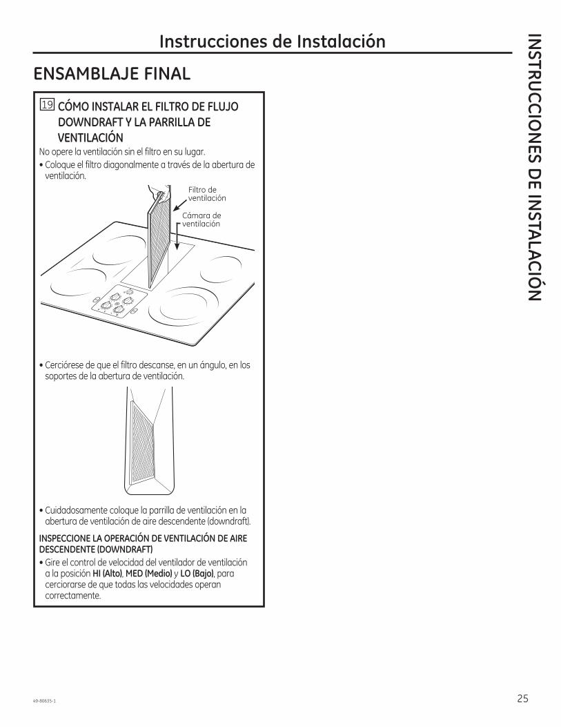
49-80635-1 25
INSTRU
CCIO
NES D
E INSTA
LACIÓ
NInstrucciones de Instalación
ENSAMBLAJE FINAL
19 CÓMO INSTALAR EL FILTRO DE FLUJO DOWNDRAFT Y LA PARRILLA DE VENTILACIÓN
No opere la ventilación sin el filtro en su lugar.• Coloque el filtro diagonalmente a través de la abertura de
ventilación.
• Cerciórese de que el filtro descanse, en un ángulo, en los soportes de la abertura de ventilación.
• Cuidadosamente coloque la parrilla de ventilación en la abertura de ventilación de aire descendente (downdraft).
INSPECCIONE LA OPERACIÓN DE VENTILACIÓN DE AIRE DESCENDENTE (DOWNDRAFT)• Gire el control de velocidad del ventilador de ventilación
a la posición HI (Alto), MED (Medio) y LO (Bajo), para cerciorarse de que todas las velocidades operan correctamente.
Filtro de ventilación
Cámara de ventilación

26 49-80635-1
Notas

49-80635-1 27
Notas

28 49-80635-1
¡Ahorre tiempo y dinero! Primero revise los cuadros que aparecen en las siguientes páginas y es posible que no necesite solicitar reparaciones.
Consejos para la Solución de Problemas... Antes de solicitar el servicio técnicoCO
NSE
JOS
PARA
LA
SO
LUC
IÓN
DE
PRO
BLEM
AS
Problema Causa Posible Qué HacerEl agua no hierve
Las unidades de superficie no se mantienen hirviendo o la cocción es lenta
Instrumentos de cocina inapropiados siendo usados.
cocina seleccionada.
Las unidades de superficie no funcionan apropiadamente
Un fusible en su casa podría haberse volado o el interruptor de circuito se aterrizó.Los controles de la estufa están colocados inapropiadamente.
Rasguños diminutos o marcas de metal (podrían parecer grietas) o abrasiones sobre la superficie de vidrio de la estufa radiante
Métodos de limpieza incorrectos siendo usados.Sartenes con el fondo áspero están siendo usadas o hubo partículas gruesas (sal o arena) entre la sartén y la superficie de la estufa.
La sartén se ha deslizado a través de la superficie de la estufa.
Áreas de decoloración o rayas oscuras en la estufa
Sartenes inapropiadas siendo usadas.
Superficies calientes en un modelo con una estufa de color pálido.
Derrames de comida que no se limpiaron hasta el siguiente uso.Uso de métodos incorrectos de limpieza.
Mezclas de azúcar caliente o plástico se derritió sobre la superficie
La sartén caliente se puso en contacto con estas sustancias.
Picadura (o hendidura) de la cocina
Mezcla de azúcar caliente derramada o plástico derretido en la cocina.
La cocina emite un sonido que se puede escuchar
La cocina está bloqueada.
Ciclos entre apagado y encendido en las unidades de superficie
Sartenes inapropiadas siendo usadas.ciclos.
La estufa se siente caliente Sartenes inapropiadas siendo usadas.
El botón de control no gira Los controles de la estufa están ajustados inapropiadamente.
Ventilación deficiente Filtro tapado.La casa demasiado cerrada.
de aire.
La tapa de la pared está obstruida.La tapa del regulador de tiro de la pare está atascada.La longitud del conducto excede el máximo de 100 pies recomendado. del conducto.