48-port t1/e1 cem interface module configuration guide ... · 48-port t1/e1 cem interface module...
TRANSCRIPT

48-Port T1/E1 CEM Interface Module Configuration Guide, Cisco IOSXE 3S (Cisco ASR 900 Series)First Published: 2016-07-29
Americas HeadquartersCisco Systems, Inc.170 West Tasman DriveSan Jose, CA 95134-1706USAhttp://www.cisco.comTel: 408 526-4000 800 553-NETS (6387)Fax: 408 527-0883
Text Part Number:

© Cisco Systems, Inc. All rights reserved.

C O N T E N T S
C H A P T E R 1 Configuring T1/E1 Interfaces on 48-Port T1/E1 Interface Module 1
Information About T1/E1 Interfaces 1
Overview of T1/E1 Interfaces 1
Restrictions for Configuring T1/E1 Interfaces 2
How to Configure T1/E1 Interfaces 2
Setting the Card Type 2
Configuring the Controller 2
Verifying the Controller Configuration 3
Configuring Structure-Agnostic TDM over Packet - T1/E1 Interfaces 3
Verifying CEM Configuration for SAToP 3
Performance Monitoring 4
Circuit Emulation Service over Packet-Switched Network 4
Restrictions for CESoPSN on T1 Interface 5
Configuring CEM Group for CESoPSN on T1 Interface 5
Verifying CEM for CESoPSN on T1 Interface 6
Troubleshooting T1/E1 Controllers 7
Running Bit Error Rate Testing for SAToP 7
Configuring BERT for SAToP 8
Verifying BERT Configuration for SAToP 8
Bit Error Rate Testing for CESoPSN 9
Restrictions for BERT in CESoPSN 9
Configuring BERT for CESoPSN 10
Verifying BERT Configuration for CESoPSN 10
Loopback on T1/E1 Interfaces 11
Configuring Loopback 12
Associated Commands 12
Additional References for Configuring 48-Port T1/E1 CEM Interface Module 14
48-Port T1/E1 CEM Interface Module Configuration Guide, Cisco IOS XE 3S (Cisco ASR 900 Series) iii
C H A P T E R 2 Overview of Circuit Emulation 17
Configuring Pseudowire 17
Information About Pseudowire 17
Overview of Pseudowire 17
How to Configure Pseudowire 18
Structure-Agnostic TDM over Packet 18
Configuring CEM for SAToP 18
Configuring CEM Group for SAToP for T1 Interfaces 18
Configuring CEM Classes 19
Configuring CEM Parameters 19
Configuring Payload Size 19
Setting the Dejitter Buffer Size 19
Shutting Down a CEM Channel 19
Configuring CEM Parameter on CEM Interface 20
Verifying CEM Statistics for SAToP 20
Circuit Emulation Service over Packet-Switched Network 21
Restrictions for CESoPSN on T1 Interface 21
Configuring CEM Group for CESoPSN on T1 Interface 21
Verifying CEM for CESoPSN on T1 Interface 22
Configuring DS1 Local Connet 23
Verifying DS1 Local Connect 24
Associated Commands 24
Additional References for Configuring Pseudowire 24
C H A P T E R 3 Alarm History 27
Alarm History Restrictions 27
Configuring Alarm History 28
Verification of Alarm History Configuration 28
Associated Commands 29
Additional References for Alarm History 29
C H A P T E R 4 Clock Recovery System for SAToP 31
Finding Feature Information 31
Information About Clock Recovery 31
48-Port T1/E1 CEM Interface Module Configuration Guide, Cisco IOS XE 3S (Cisco ASR 900 Series)iv
Contents
Adaptive Clock Recovery (ACR) 31
Differential Clock Recovery (DCR) 32
Benefits of Clock Recovery 32
Prerequisites for Clock Recovery 33
Restrictions for Clock Recovery 33
How to Configure ACR and DCR 33
Configuring ACR for T1/E1 33
Configuring Adaptive Clock Recovery of T1/E1 Interfaces for SAToP 33
Verifying the Adaptive Clock Recovery Configuration of T1/E1 Interfaces for
SAToP 34
Configuring DCR for T1/E1 34
Configuring Differential Clock Recovery of T1/E1 Interfaces for SAToP 34
Verifying the Differential Clock Recovery Configuration of T1/E1 Interfaces for
SAToP 35
Configuring Network Clock 36
Verifying Network Clocking Configuration 36
Associated Commands 36
Additional References for Clock Recovery 37
48-Port T1/E1 CEM Interface Module Configuration Guide, Cisco IOS XE 3S (Cisco ASR 900 Series) v
Contents

48-Port T1/E1 CEM Interface Module Configuration Guide, Cisco IOS XE 3S (Cisco ASR 900 Series)vi
Contents

C H A P T E R 1Configuring T1/E1 Interfaces on 48-Port T1/E1Interface Module
This chapter provides information about configuring the T1/E1 interfaces on the 48-Port T1/E1 interfacemodule:
Effective Cisco IOS XE Release 16.5.1S, E1 interface is supported.
T1/E1 is supported only on Cisco ASR 900 RSP3 Module.
Note
• Information About T1/E1 Interfaces, page 1
• How to Configure T1/E1 Interfaces, page 2
• Circuit Emulation Service over Packet-Switched Network, page 4
• Troubleshooting T1/E1 Controllers, page 7
• Associated Commands, page 12
• Additional References for Configuring 48-Port T1/E1 CEM Interface Module , page 14
Information About T1/E1 InterfacesThe following sections provide information about T1/E1 interfaces.
Overview of T1/E1 InterfacesThe 48-Port T1/E1 interface module on CEM line card supports generic single or dual-port T1/E1 trunkinterfaces for voice, data, and integrated voice or data applications.
48-Port T1/E1 CEM Interface Module Configuration Guide, Cisco IOS XE 3S (Cisco ASR 900 Series) 1

Restrictions for Configuring T1/E1 Interfaces• You can configure CEM to support serial interface configuration.
• The supported BERT patterns are 1s, 2^11, 2^15, 2^20-O153, 2^20-QRSS, and 2^23.
• DS0 level channelization is not supported.
How to Configure T1/E1 InterfacesThis section provides information about configuring T1/E1 interfaces on the 48-Port T1/E1 interface module
Recommended Pattern for Lincecode
The following pattern for linecode confirguration is supported for DS1/E1.
Random PatternT1/E1Linecode ConfigurationPart Number
QRSST1B8ZS/AMIXRT83VSH316 LIU
PRBS15E1HDB3/AMI
Setting the Card TypeTo set the card type for the T1/E1 interfaces, complete these steps:
enableconfigure terminalcard type t1/e1 0 0exit
Configuring the ControllerTo configure T1 interface, use the following commands:
enableconfigure terminalcontroller t1 0/3/0clock source internalframing esfcablelength short 110linecode b8zsno shutexit
For T1 interface, the default frame mode is Extended Super Frame (ESF).Note
48-Port T1/E1 CEM Interface Module Configuration Guide, Cisco IOS XE 3S (Cisco ASR 900 Series)2
Configuring T1/E1 Interfaces on 48-Port T1/E1 Interface ModuleRestrictions for Configuring T1/E1 Interfaces
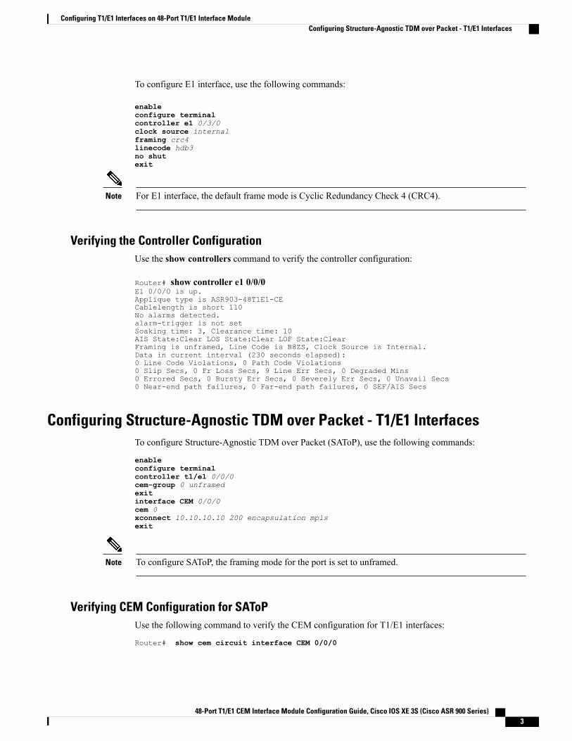
To configure E1 interface, use the following commands:
enableconfigure terminalcontroller e1 0/3/0clock source internalframing crc4linecode hdb3no shutexit
For E1 interface, the default frame mode is Cyclic Redundancy Check 4 (CRC4).Note
Verifying the Controller ConfigurationUse the show controllers command to verify the controller configuration:
Router# show controller e1 0/0/0E1 0/0/0 is up.Applique type is ASR903-48T1E1-CECablelength is short 110No alarms detected.alarm-trigger is not setSoaking time: 3, Clearance time: 10AIS State:Clear LOS State:Clear LOF State:ClearFraming is unframed, Line Code is B8ZS, Clock Source is Internal.Data in current interval (230 seconds elapsed):0 Line Code Violations, 0 Path Code Violations0 Slip Secs, 0 Fr Loss Secs, 9 Line Err Secs, 0 Degraded Mins0 Errored Secs, 0 Bursty Err Secs, 0 Severely Err Secs, 0 Unavail Secs0 Near-end path failures, 0 Far-end path failures, 0 SEF/AIS Secs
Configuring Structure-Agnostic TDM over Packet - T1/E1 InterfacesTo configure Structure-Agnostic TDM over Packet (SAToP), use the following commands:
enableconfigure terminalcontroller t1/e1 0/0/0cem-group 0 unframedexitinterface CEM 0/0/0cem 0xconnect 10.10.10.10 200 encapsulation mplsexit
To configure SAToP, the framing mode for the port is set to unframed.Note
Verifying CEM Configuration for SAToPUse the following command to verify the CEM configuration for T1/E1 interfaces:
Router# show cem circuit interface CEM 0/0/0
48-Port T1/E1 CEM Interface Module Configuration Guide, Cisco IOS XE 3S (Cisco ASR 900 Series) 3
Configuring T1/E1 Interfaces on 48-Port T1/E1 Interface ModuleConfiguring Structure-Agnostic TDM over Packet - T1/E1 Interfaces
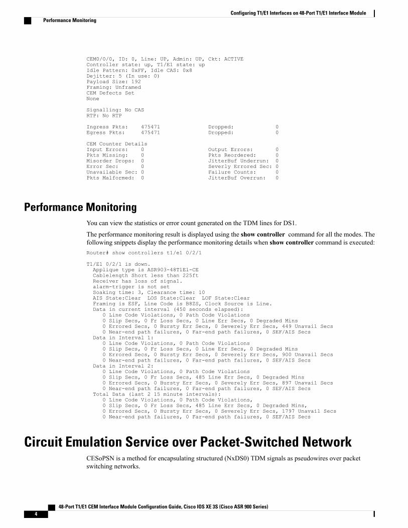
CEM0/0/0, ID: 0, Line: UP, Admin: UP, Ckt: ACTIVEController state: up, T1/E1 state: upIdle Pattern: 0xFF, Idle CAS: 0x8Dejitter: 5 (In use: 0)Payload Size: 192Framing: UnframedCEM Defects SetNone
Signalling: No CASRTP: No RTP
Ingress Pkts: 475471 Dropped: 0Egress Pkts: 475471 Dropped: 0
CEM Counter DetailsInput Errors: 0 Output Errors: 0Pkts Missing: 0 Pkts Reordered: 0Misorder Drops: 0 JitterBuf Underrun: 0Error Sec: 0 Severly Errored Sec: 0Unavailable Sec: 0 Failure Counts: 0Pkts Malformed: 0 JitterBuf Overrun: 0
Performance MonitoringYou can view the statistics or error count generated on the TDM lines for DS1.
The performance monitoring result is displayed using the show controller command for all the modes. Thefollowing snippets display the performance monitoring details when show controller command is executed:Router# show controllers t1/e1 0/2/1
T1/E1 0/2/1 is down.Applique type is ASR903-48T1E1-CECablelength Short less than 225ftReceiver has loss of signal.alarm-trigger is not setSoaking time: 3, Clearance time: 10AIS State:Clear LOS State:Clear LOF State:ClearFraming is ESF, Line Code is B8ZS, Clock Source is Line.Data in current interval (450 seconds elapsed):
0 Line Code Violations, 0 Path Code Violations0 Slip Secs, 0 Fr Loss Secs, 0 Line Err Secs, 0 Degraded Mins0 Errored Secs, 0 Bursty Err Secs, 0 Severely Err Secs, 449 Unavail Secs0 Near-end path failures, 0 Far-end path failures, 0 SEF/AIS Secs
Data in Interval 1:0 Line Code Violations, 0 Path Code Violations0 Slip Secs, 0 Fr Loss Secs, 0 Line Err Secs, 0 Degraded Mins0 Errored Secs, 0 Bursty Err Secs, 0 Severely Err Secs, 900 Unavail Secs0 Near-end path failures, 0 Far-end path failures, 0 SEF/AIS Secs
Data in Interval 2:0 Line Code Violations, 0 Path Code Violations0 Slip Secs, 0 Fr Loss Secs, 485 Line Err Secs, 0 Degraded Mins0 Errored Secs, 0 Bursty Err Secs, 0 Severely Err Secs, 897 Unavail Secs0 Near-end path failures, 0 Far-end path failures, 0 SEF/AIS Secs
Total Data (last 2 15 minute intervals):0 Line Code Violations, 0 Path Code Violations,0 Slip Secs, 0 Fr Loss Secs, 485 Line Err Secs, 0 Degraded Mins,0 Errored Secs, 0 Bursty Err Secs, 0 Severely Err Secs, 1797 Unavail Secs0 Near-end path failures, 0 Far-end path failures, 0 SEF/AIS Secs
Circuit Emulation Service over Packet-Switched NetworkCESoPSN is a method for encapsulating structured (NxDS0) TDM signals as pseudowires over packetswitching networks.
48-Port T1/E1 CEM Interface Module Configuration Guide, Cisco IOS XE 3S (Cisco ASR 900 Series)4
Configuring T1/E1 Interfaces on 48-Port T1/E1 Interface ModulePerformance Monitoring

Restrictions for CESoPSN on T1 Interface• The maximum number of CEM interface supported is 192.
• The DS0 loopback is not supported on the T1 interface.
• The alarm forwarding is not supported on the T1 interface.
• The card protection is not supported on the T1 interface.
Configuring CEM Group for CESoPSN on T1 InterfaceThe following section describes how to configure a CEM group for CESoPSN.
To configure xconnect over MPLS, use the following commands:
enableconfigure terminalcontrol t1 0/4/32cem-group 0 timeslots 1-10
Configure xconnect:
enableconfigure terminalinterface cem 0/4/32cem 0xconnect 2.2.2.2 10 encapsulation mpls
Perform a similar configuration on the other end of the pseudowire.
sh running-config | sec 0/8/16controller T1 0/8/16framing esflinecode b8zscablelength short 110cem-group 0 timeslots 1-10
interface CEM0/8/16no ip addresscem 0xconnect 2.2.2.2 10 encapsulation mpls
Check for xconnect configuration using the following command:
PE1#sh xconnect all | i 0/4/32UP pri ac CE0/4/32:0(CESoPSN Basic) UP mpls 2.2.2.2:10 UP
PE1#sh controllers t1 0/4/32T1 0/4/32 is upApplique type is NCS4200-48T1E1-CECablelength is short 110No alarms detected.alarm-trigger is not setSoaking time: 3, Clearance time: 10AIS State:Clear LOS State:Clear LOF State:ClearFraming is ESF, Line Code is B8ZS, Clock Source is Line.
48-Port T1/E1 CEM Interface Module Configuration Guide, Cisco IOS XE 3S (Cisco ASR 900 Series) 5
Configuring T1/E1 Interfaces on 48-Port T1/E1 Interface ModuleRestrictions for CESoPSN on T1 Interface

Verifying CEM for CESoPSN on T1 InterfaceUse the following commands to verify the pseudowire configuration for CESoPSN:
• show cem circuit—Displays information about the circuit state, administrative state, the CEM ID of thecircuit, and the interface on which it is configured. If cross connect is configured under the circuit, thecommand output also includes information about the attachment circuit status.
• show mpls l2 vc—Displays information about the MPLS VC.
• show mpls l2 vc detail—Displays detailed information about the MPLS VC.
PE1#show mpls l2 vc 10
Local intf Local circuit Dest address VC ID Status------------- -------------------------- --------------- ---------- ----------CE0/4/32 CESoPSN Basic 0 2.2.2.2 10 UP
PE1#sh mpls l2 vc 10 detPE1#sh mpls l2 vc 10 detailLocal interface: CE0/4/32 up, line protocol up, CESoPSN Basic 0 upDestination address: 2.2.2.2, VC ID: 10, VC status: upOutput interface: Te0/0/0, imposed label stack {650}Preferred path: not configuredDefault path: activeNext hop: 123.123.123.2
Create time: 00:21:25, last status change time: 00:21:25Last label FSM state change time: 00:21:25
Signaling protocol: LDP, peer 2.2.2.2:0 upTargeted Hello: 1.1.1.1(LDP Id) -> 2.2.2.2, LDP is UPGraceful restart: configured and not enabledNon stop routing: not configured and not enabledStatus TLV support (local/remote) : enabled/supportedLDP route watch : enabledLabel/status state machine : established, LruRruLast local dataplane status rcvd: No faultLast BFD dataplane status rcvd: Not sentLast BFD peer monitor status rcvd: No faultLast local AC circuit status rcvd: No faultLast local AC circuit status sent: No faultLast local PW i/f circ status rcvd: No faultLast local LDP TLV status sent: No faultLast remote LDP TLV status rcvd: No faultLast remote LDP ADJ status rcvd: No fault
MPLS VC labels: local 577, remote 650Group ID: local 238, remote 276MTU: local 0, remote 0Remote interface description:
Sequencing: receive disabled, send disabledControl Word: On (configured: autosense)SSO Descriptor: 2.2.2.2/10, local label: 577Dataplane:SSM segment/switch IDs: 6893171/4140658 (used), PWID: 674
VC statistics:transit packet totals: receive 0, send 0transit byte totals: receive 0, send 0transit packet drops: receive 0, seq error 0, send 0
Router#show cem circuit int cem 0/4/32
CEM0/4/32, ID: 0, Line: UP, Admin: UP, Ckt: ACTIVEMode :T1, CEM Mode: T1-CESoPController state: up, T1/E1 state: upIdle Pattern: 0xFF, Idle CAS: 0x8Dejitter: 5 (In use: 0)Payload Size: 80Framing: Framed (DS0 channels: 1-10)
48-Port T1/E1 CEM Interface Module Configuration Guide, Cisco IOS XE 3S (Cisco ASR 900 Series)6
Configuring T1/E1 Interfaces on 48-Port T1/E1 Interface ModuleVerifying CEM for CESoPSN on T1 Interface

CEM Defects SetNone
Signalling: No CASRTP: No RTP
Ingress Pkts: 203997 Dropped: 0Egress Pkts: 203999 Dropped: 0
CEM Counter DetailsInput Errors: 0 Output Errors: 0Pkts Missing: 0 Pkts Reordered: 0Misorder Drops: 0 JitterBuf Underrun: 0Error Sec: 0 Severly Errored Sec: 0Unavailable Sec: 0 Failure Counts: 0Pkts Malformed: 0 JitterBuf Overrun: 0Generated Lbits: 0 Received Lbits: 0Generated Rbits: 0 Received Rbits: 0Generated Mbits: 0 Received Mbits: 0
Troubleshooting T1/E1 ControllersYou can use the following methods to troubleshoot the T1/E1 controllers:
Running Bit Error Rate Testing for SAToPBit error rate testing (BERT) is supported on T1/E1 interfaces. You can run BERTs on 16 controllers out of48 T1/E1 controllers at a time.
The interface module contains onboard BERT circuitry. With this, the interface module software can sendand detect a programmable pattern that is compliant with CCITT/ITU O.151, O.152, O.153 pseudo-randomand repetitive test patterns. BERT allows you to test cables and signal problems in the field.
When running a BERT test, your system expects to receive the same pattern that it is transmitting. To helpensure this, two common options are available:
• Use a loopback somewhere in the link or network
• Configure remote testing equipment to transmit the same BERT test pattern at the same time
The following keywords list different BERT keywords and their descriptions.
Table 1: BERT Pattern Descriptions
DescriptionKeyword
Repeating pattern of ones (...111...).1s
Pseudo-random test pattern that is 2,048 bits in length.2^11
Pseudo-random O.151 test pattern that is 32,768 bitsin length.
2^15
Pseudo-random O.153 test pattern that is 1,048,575bits in length.
2^20-O153
48-Port T1/E1 CEM Interface Module Configuration Guide, Cisco IOS XE 3S (Cisco ASR 900 Series) 7
Configuring T1/E1 Interfaces on 48-Port T1/E1 Interface ModuleTroubleshooting T1/E1 Controllers
DescriptionKeyword
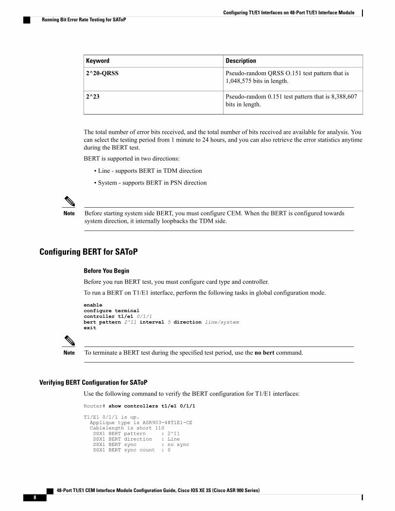
Pseudo-random QRSS O.151 test pattern that is1,048,575 bits in length.
2^20-QRSS
Pseudo-random 0.151 test pattern that is 8,388,607bits in length.
2^23
The total number of error bits received, and the total number of bits received are available for analysis. Youcan select the testing period from 1 minute to 24 hours, and you can also retrieve the error statistics anytimeduring the BERT test.
BERT is supported in two directions:
• Line - supports BERT in TDM direction
• System - supports BERT in PSN direction
Before starting system side BERT, you must configure CEM. When the BERT is configured towardssystem direction, it internally loopbacks the TDM side.
Note
Configuring BERT for SAToP
Before You Begin
Before you run BERT test, you must configure card type and controller.
To run a BERT on T1/E1 interface, perform the following tasks in global configuration mode.
enableconfigure terminalcontroller t1/e1 0/1/1bert pattern 2^11 interval 5 direction line/systemexit
To terminate a BERT test during the specified test period, use the no bert command.Note
Verifying BERT Configuration for SAToP
Use the following command to verify the BERT configuration for T1/E1 interfaces:
Router# show controllers t1/e1 0/1/1
T1/E1 0/1/1 is up.Applique type is ASR903-48T1E1-CECablelength is short 110DSX1 BERT pattern : 2^11DSX1 BERT direction : LineDSX1 BERT sync : no syncDSX1 BERT sync count : 0
48-Port T1/E1 CEM Interface Module Configuration Guide, Cisco IOS XE 3S (Cisco ASR 900 Series)8
Configuring T1/E1 Interfaces on 48-Port T1/E1 Interface ModuleRunning Bit Error Rate Testing for SAToP

DSX1 BERT interval : 5DSX1 BERT time remain : 2DSX1 BERT total errs : 0DSX1 BERT total k bits: 0DSX1 BERT errors (last): 0DSX1 BERT k bits (last): 0Last clearing of BERT counters neverNo alarms detected.alarm-trigger is not setSoaking time: 3, Clearance time: 10AIS State:Clear LOS State:Clear LOF State:ClearFraming is unframed, Line Code is B8ZS, Clock Source is Internal.Data in current interval (320 seconds elapsed):
0 Line Code Violations, 0 Path Code Violations0 Slip Secs, 0 Fr Loss Secs, 0 Line Err Secs, 0 Degraded Mins0 Errored Secs, 0 Bursty Err Secs, 0 Severely Err Secs, 0 Unavail Secs0 Near-end path failures, 0 Far-end path failures, 0 SEF/AIS Secs
Total Data (last 3 15 minute intervals):0 Line Code Violations, 0 Path Code Violations,0 Slip Secs, 0 Fr Loss Secs, 0 Line Err Secs, 0 Degraded Mins,0 Errored Secs, 0 Bursty Err Secs, 0 Severely Err Secs, 0 Unavail Secs0 Near-end path failures, 0 Far-end path failures, 0 SEF/AIS Secs
You can view the results of a BERT test at the following times:
• After you terminate the test using the no bert command
• After the test runs completely
• Anytime during the test (in real time)
Bit Error Rate Testing for CESoPSNBit-Error Rate Testing (BERT) is used for analyzing quality and problem resolution of digital transmissionequipment. BERT tests the quality of an interface by directly comparing a pseudorandom or repetitive testpattern with an identical locally generated test pattern. BERT is supported at the TDM side and pseudowireside. BERT can be used either at NxDS0 or DS1 but not together.
BERT is supported on following controllers:
• T1 NxDS0, DS1
• T3 NxDS0, DS1 (channelised), clear channel DS3.
• OCX NxDS0, DS1 (channelised),DS3(channelised), clear channel DS3,STS1,STS-nc,VT-1.5,VT1.5T1
Restrictions for BERT in CESoPSN• The Cisco ASR 900 Series Router supports only the following BERT patterns: 2^11, 2^15, 2^20-O153,and 2^20-QRSS.
• For the line side BERT to be configured at timeslot level, the first CEM should be configured and itshould be present at the same timeslot level where the BERT is configured.
• The system side BERT is not supported on partial timeslots. For the system side BERT, use full timeslots.
48-Port T1/E1 CEM Interface Module Configuration Guide, Cisco IOS XE 3S (Cisco ASR 900 Series) 9
Configuring T1/E1 Interfaces on 48-Port T1/E1 Interface ModuleBit Error Rate Testing for CESoPSN
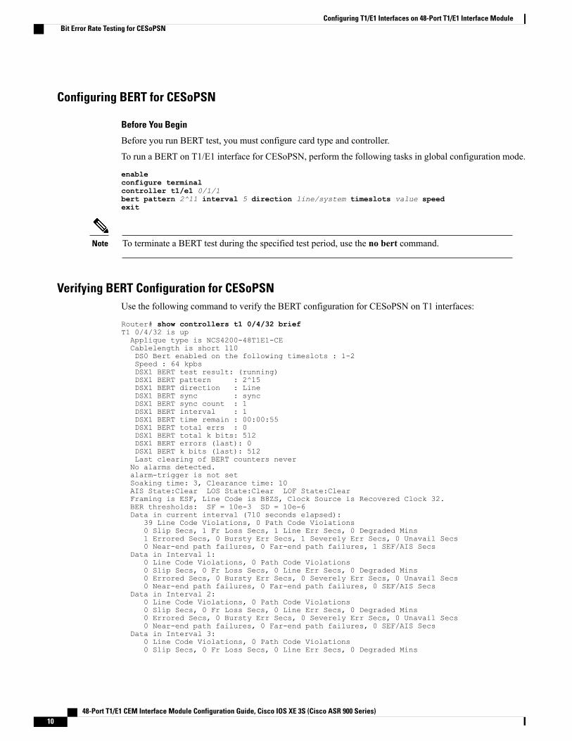
Configuring BERT for CESoPSN
Before You Begin
Before you run BERT test, you must configure card type and controller.
To run a BERT on T1/E1 interface for CESoPSN, perform the following tasks in global configuration mode.
enableconfigure terminalcontroller t1/e1 0/1/1bert pattern 2^11 interval 5 direction line/system timeslots value speedexit
To terminate a BERT test during the specified test period, use the no bert command.Note
Verifying BERT Configuration for CESoPSNUse the following command to verify the BERT configuration for CESoPSN on T1 interfaces:
Router# show controllers t1 0/4/32 briefT1 0/4/32 is upApplique type is NCS4200-48T1E1-CECablelength is short 110DS0 Bert enabled on the following timeslots : 1-2Speed : 64 kpbsDSX1 BERT test result: (running)DSX1 BERT pattern : 2^15DSX1 BERT direction : LineDSX1 BERT sync : syncDSX1 BERT sync count : 1DSX1 BERT interval : 1DSX1 BERT time remain : 00:00:55DSX1 BERT total errs : 0DSX1 BERT total k bits: 512DSX1 BERT errors (last): 0DSX1 BERT k bits (last): 512Last clearing of BERT counters neverNo alarms detected.alarm-trigger is not setSoaking time: 3, Clearance time: 10AIS State:Clear LOS State:Clear LOF State:ClearFraming is ESF, Line Code is B8ZS, Clock Source is Recovered Clock 32.BER thresholds: SF = 10e-3 SD = 10e-6Data in current interval (710 seconds elapsed):
39 Line Code Violations, 0 Path Code Violations0 Slip Secs, 1 Fr Loss Secs, 1 Line Err Secs, 0 Degraded Mins1 Errored Secs, 0 Bursty Err Secs, 1 Severely Err Secs, 0 Unavail Secs0 Near-end path failures, 0 Far-end path failures, 1 SEF/AIS Secs
Data in Interval 1:0 Line Code Violations, 0 Path Code Violations0 Slip Secs, 0 Fr Loss Secs, 0 Line Err Secs, 0 Degraded Mins0 Errored Secs, 0 Bursty Err Secs, 0 Severely Err Secs, 0 Unavail Secs0 Near-end path failures, 0 Far-end path failures, 0 SEF/AIS Secs
Data in Interval 2:0 Line Code Violations, 0 Path Code Violations0 Slip Secs, 0 Fr Loss Secs, 0 Line Err Secs, 0 Degraded Mins0 Errored Secs, 0 Bursty Err Secs, 0 Severely Err Secs, 0 Unavail Secs0 Near-end path failures, 0 Far-end path failures, 0 SEF/AIS Secs
Data in Interval 3:0 Line Code Violations, 0 Path Code Violations0 Slip Secs, 0 Fr Loss Secs, 0 Line Err Secs, 0 Degraded Mins
48-Port T1/E1 CEM Interface Module Configuration Guide, Cisco IOS XE 3S (Cisco ASR 900 Series)10
Configuring T1/E1 Interfaces on 48-Port T1/E1 Interface ModuleBit Error Rate Testing for CESoPSN

0 Errored Secs, 0 Bursty Err Secs, 0 Severely Err Secs, 0 Unavail Secs0 Near-end path failures, 0 Far-end path failures, 0 SEF/AIS Secs
Data in Interval 4:0 Line Code Violations, 0 Path Code Violations0 Slip Secs, 0 Fr Loss Secs, 0 Line Err Secs, 0 Degraded Mins
You can view the results of a BERT test at the following times:
• After you terminate the test using the no bert command
• After the test runs completely
• Anytime during the test (in real time)
Loopback on T1/E1 Interfaces
Loopback Description
You can use the following loopback on the T1/E1 interfaces.
DescriptionLoopback
Loops the outgoing transmit signal back to the receivesignal. This is done using the diagnostic loopbackfeature in the interface module’s framer. The interfacetransmits AIS in this mode. Set the clock sourcecommand to internal for this loopback mode.
loopback diag
Loops the incoming receive signal back out to thetransmitter. You can specify whether to use the lineor payload.
Loopback local is supported on E1 interface.
loopback local
The incoming signal is looped back in the interfaceusing the framer’s line loopback mode. The framerdoes not reclock or reframe the incoming data. Allincoming data is received by the interface driver.
loopback local line
Loops the incoming signal back in the interface usingthe payload loopbackmode of the framer. The framerreclocks and reframes the incoming data beforesending it back out to the network.
Loopback Local Payload support is availableonly when framing is ESF.
Note
loopback local payload
Loops the incoming signal back in the interfacemodule using the line loopback mode of the framer.The framer does not reclock or reframe the incomingdata. All incoming data is received by the interfacemodule driver.
Loopback network line is supported on E1 interface.
loopback network line
48-Port T1/E1 CEM Interface Module Configuration Guide, Cisco IOS XE 3S (Cisco ASR 900 Series) 11
Configuring T1/E1 Interfaces on 48-Port T1/E1 Interface ModuleLoopback on T1/E1 Interfaces

Configuring Loopback
Before You Begin
Before you configure loopback, you must configure the controller and the CEM.
To set a loopback local on the T1 interface, perform the following tasks in global configuration mode:
enableconfigure terminalcontroller t1 0/0/1loopback local lineexit
To set a loopback diag on the T1 interface, perform the following tasks in global configuration mode:
enableconfigure terminalcontroller t1 0/0/1loopbackdiagexit
To set a loopback local on the E1 interface, perform the following tasks in global configuration mode:
enableconfigure terminalcontroller e1 0/0/1loopback localexit
To set a loopback network on the E1 interface, perform the following tasks in global configuration mode:
enableconfigure terminalcontroller e1 0/0/1loopback network lineexit
To remove a loopback, use the no loopback command.Note
Associated CommandsThe commands used to configure the Interfaces.
URLCommands
http://www.cisco.com/c/en/us/td/docs/ios-xml/ios/interface/command/ir-cr-book/ir-c1.html#wp2336574570
card type
http://www.cisco.com/c/en/us/td/docs/ios-xml/ios/interface/command/ir-cr-book/ir-c1.html#wp2440628600
cem-group
48-Port T1/E1 CEM Interface Module Configuration Guide, Cisco IOS XE 3S (Cisco ASR 900 Series)12
Configuring T1/E1 Interfaces on 48-Port T1/E1 Interface ModuleAssociated Commands

URLCommands
https://www.cisco.com/c/en/us/td/docs/ios-xml/ios/interface/command/ir-cr-book/ir-o1.html#wp3946673156
payload-size dejitter-buffer
https://www.cisco.com/c/en/us/td/docs/ios-xml/ios/interface/command/ir-cr-book/ir-c1.html#wp2169323859
class cem
https://www.cisco.com/c/en/us/td/docs/ios-xml/ios/interface/command/ir-cr-book/ir-c2.html#wp1472647421
controller t1/e1
http://www.cisco.com/c/en/us/td/docs/ios-xml/ios/interface/command/ir-cr-book/ir-t2.html#wp8578094790
xconnect
http://www.cisco.com/c/en/us/td/docs/ios-xml/ios/interface/command/ir-cr-book/ir-l1.html#wp2312535965
linecode
http://www.cisco.com/c/en/us/td/docs/ios-xml/ios/interface/command/ir-cr-book/ir-f1.html#wp2853515177
framing
http://www.cisco.com/c/en/us/td/docs/ios-xml/ios/interface/command/ir-cr-book/ir-c2.html#wp6081785140
clock source
http://www.cisco.com/c/en/us/td/docs/ios-xml/ios/interface/command/ir-cr-book/ir-c1.html#wp2492964151
cable length
http://www.cisco.com/c/en/us/td/docs/ios-xml/ios/interface/command/ir-cr-book/ir-a1.html#wp3620978929
bert pattern
http://www.cisco.com/c/en/us/td/docs/ios-xml/ios/interface/command/ir-cr-book/ir-c1.html#wp7026926390
channelized
http://www.cisco.com/c/en/us/td/docs/ios-xml/ios/interface/command/ir-cr-book/ir-l1.html#wp1033903426
loopback
http://www.cisco.com/c/en/us/td/docs/ios-xml/ios/interface/command/ir-cr-book/ir-s3.html#wp2149471094
show controller t1
48-Port T1/E1 CEM Interface Module Configuration Guide, Cisco IOS XE 3S (Cisco ASR 900 Series) 13
Configuring T1/E1 Interfaces on 48-Port T1/E1 Interface ModuleAssociated Commands

URLCommands
http://www.cisco.com/c/en/us/td/docs/ios-xml/ios/interface/command/ir-cr-book/ir-s2.html#wp1632676058
show controller e1
Additional References for Configuring 48-Port T1/E1 CEMInterface Module
Related Documents
Document TitleRelated Topic
Cisco IOS Master Commands List, All ReleasesCisco IOS commands
Standards and RFCs
TitleStandard/RFC
There are no standards and RFCs for this feature.—
MIBs
MIBs LinkMIB
To locate and downloadMIBs for selected platforms,Cisco IOS releases, and feature sets, use Cisco MIBLocator found at the following URL:
http://www.cisco.com/go/mibs
—
48-Port T1/E1 CEM Interface Module Configuration Guide, Cisco IOS XE 3S (Cisco ASR 900 Series)14
Configuring T1/E1 Interfaces on 48-Port T1/E1 Interface ModuleAdditional References for Configuring 48-Port T1/E1 CEM Interface Module
Technical Assistance
LinkDescription
http://www.cisco.com/cisco/web/support/index.htmlThe Cisco Support website provides extensive onlineresources, including documentation and tools fortroubleshooting and resolving technical issues withCisco products and technologies.
To receive security and technical information aboutyour products, you can subscribe to various services,such as the Product Alert Tool (accessed from FieldNotices), the Cisco Technical Services Newsletter,and Really Simple Syndication (RSS) Feeds.
Access to most tools on the Cisco Support websiterequires a Cisco.com user ID and password.
48-Port T1/E1 CEM Interface Module Configuration Guide, Cisco IOS XE 3S (Cisco ASR 900 Series) 15
Configuring T1/E1 Interfaces on 48-Port T1/E1 Interface ModuleAdditional References for Configuring 48-Port T1/E1 CEM Interface Module
48-Port T1/E1 CEM Interface Module Configuration Guide, Cisco IOS XE 3S (Cisco ASR 900 Series)16
Configuring T1/E1 Interfaces on 48-Port T1/E1 Interface ModuleAdditional References for Configuring 48-Port T1/E1 CEM Interface Module

C H A P T E R 2Overview of Circuit Emulation
Circuit Emulation (CEM) is a technology that provides a protocol-independent transport over IP/MPLSnetworks. It enables proprietary or legacy applications to be carried transparently to the destination, similarto a leased line.
CEM provides a bridge between a Time-Division Multiplexing (TDM) network and Multiprotocol LabelSwitching (MPLS) network. The chassis encapsulates the TDM data in the MPLS packets and sends thedata over a CEM pseudowire to the remote Provider Edge (PE) chassis. As a result, CEM functions as aphysical communication link across the packet network.
The chassis supports the pseudowire type that utilizes CEM transport: Structure-Agnostic TDM over Packet(SAToP).
L2VPN over IP/MPLS is also supported on the interface modules.
• Configuring Pseudowire, page 17
Configuring PseudowireCisco Pseudowire Emulation Edge-to-Edge (PWE3) allows you to transport traffic by using traditional servicessuch as T1/E1 over a packet-based backhaul technology such as MPLS or IP. A pseudowire (PW) consistsof a connection between two provider edge (PE) chassis that connects two attachment circuits (ACs), such asT1/E1 or T3 /E3 links.
Information About PseudowireThe following sections describe how to configure pseudowire on the interface module of the chassis.
Overview of PseudowirePseudowires manage encapsulation, timing, order, and other operations in order to make it transparent tousers. The pseudowire tunnel acts as an unshared link or circuit of the emulated service.
48-Port T1/E1 CEM Interface Module Configuration Guide, Cisco IOS XE 3S (Cisco ASR 900 Series) 17

How to Configure PseudowireThe following sections describe how to configure pseudowire.
Structure-Agnostic TDM over PacketStructure-Agnostic TDM over Packet (SAToP) encapsulates Time Division Multiplexing (TDM) bit-streamsas pseudowires over public switched networks. It disregards any structure that may be imposed on streams,in particular the structure imposed by the standard TDM framing.
The protocol used for emulation of these services does not depend on the method in which attachment circuitsare delivered to the Provider Edge (PE) chassis. For example, a T1 attachment circuit is treated the same wayfor all delivery methods, including copper, multiplex in a T3 circuit, a virtual tributary of a SONET circuit,or unstructured Circuit Emulation Service (CES).
In SAToPmode, the interface is considered as a continuous framed bit stream. The packetization of the streamis done according to IETF RFC 4553. All signaling is carried out transparently as a part of a bit stream.
Configuring CEM for SAToP
This section provides information about how to configure CEM. CEM provides a bridge between a TimeDivision Multiplexing (TDM) network and a packet network, MPLS. The chassis encapsulates the TDM datain the MPLS packets and sends the data over a CEM pseudowire to the remote Provider Edge (PE) chassis.
The following sections describe how to configure CEM.
Configuring CEM Restriction
• Not all combinations of payload size and dejitter buffer size are supported. If you apply an incompatiblepayload size or dejitter buffer size configuration, the chassis rejects it and reverts to the previousconfiguration.
• The dummy-pattern command is not supported.
CEM interface does not support idle-cas parameter.Note
Configuring CEM Group for SAToP for T1 InterfacesThe following section describes how to configure a CEM group for SAToP.
enableconfigure terminalcontroller t1 0/4/0cem-group 0 unframedend
You need metroaggrservice license to configure CEM group on the Interface Module.Note
48-Port T1/E1 CEM Interface Module Configuration Guide, Cisco IOS XE 3S (Cisco ASR 900 Series)18
Overview of Circuit EmulationHow to Configure Pseudowire

Configuring CEM ClassesA CEM class allows you to create a single configuration template for multiple CEM pseudowires. Followthese steps to configure a CEM class:
Note • The CEM parameters can be configured either by using CEM class or on CEM interface directly.
• The CEM parameters at the local and remote ends of a CEM circuit must match; otherwise, thepseudowire between the local and remote PE chassis does not come up.
enableconfigure terminalclass cem mycemclasspayload-size 512dejitter-buffer 12exitinterface cem 0/0/1cem 0cem class mycemclassxconnect 10.10.10.10 200 encapsulation mplsexit
Configuring CEM ParametersThe following sections describe the parameters you can configure for CEM circuits.
Configuring Payload SizeTo specify the number of bytes encapsulated into a single IP packet, use the payload-size command. The sizeargument specifies the number of bytes in the payload of each packet. The range is from 32 to 1312 bytes.
Default payload sizes for an unstructured CEM channel are as follows:
• T1 = 192 bytes
• E1 = 256 bytes
• DS0 = 32 bytes
Default payload sizes for a structured CEM channel depend on the number of time slots that constitute thechannel. Payload size (L in bytes), number of time slots (N), and packetization delay (D in milliseconds) havethe following relationship: L = 8*N*D. The default payload size is selected in such a way that the packetizationdelay is always 1 millisecond. For example, a structured CEM channel of 16xDS0 has a default payload sizeof 128 bytes.
Both payload-size and dejitter-buffer must be configured simultaneously.Note
Setting the Dejitter Buffer SizeTo specify the size of the dejitter-buffer used to compensate for the network filter, use the dejitter-buffercommand. The configured dejitter-buffer size is converted from milliseconds to packets and rounded up tothe next integral number of packets. Use the size argument to specify the size of the buffer, in milliseconds.The range is from 1 to 32; the default is 5.
Shutting Down a CEM Channel
48-Port T1/E1 CEM Interface Module Configuration Guide, Cisco IOS XE 3S (Cisco ASR 900 Series) 19
Overview of Circuit EmulationHow to Configure Pseudowire

To shut down a CEM channel, use the shutdown command in CEM configuration mode. The shutdowncommand is supported only under CEM mode and not under the CEM class.
Configuring CEM Parameter on CEM InterfaceThe CEM parameters can be configured directly on CEM interface. Follow these steps to configure CEMparameters:
enableconfigure terminalinterface cem 0/0/1cem 0payload-size 512 dejitter-buffer 12xconnect 10.10.10.10 200 encapsulation mplsexit
Verifying CEM Statistics for SAToPUse the following commands to verify the pseudowire configuration for SAToP:
• show cem circuit—Displays information about the circuit state, administrative state, the CEM ID ofthe circuit, and the interface on which it is configured. If cross connect is configured under the circuit,the command output also includes information about the attachment circuit status.
Router# show cem circuit?
<0-32000> CEM IDdetail Detailed information of cem ckt(s)interface CEM Interfacesummary Display summary of CEM ckts| Output modifiers
Router# show cem circuit
CEM Int. ID Line Admin Circuit AC--------------------------------------------------------------CEM0/1/0 1 UP UP ACTIVE --/--CEM0/1/0 2 UP UP ACTIVE --/--CEM0/1/0 3 UP UP ACTIVE --/--CEM0/1/0 4 UP UP ACTIVE --/--CEM0/1/0 5 UP UP ACTIVE --/--
• show cem circuit cem-id— Displays the detailed information about that particular circuit.
Router# show cem circuit 0
CEM0/1/2, ID: 0, Line: UP, Admin: UP, Ckt: ACTIVEController state: up, T1/E1 state: upIdle Pattern: 0xFF, Idle CAS: 0x8Dejitter: 5 (In use: 0)Payload Size: 192Framing: UnframedCEM Defects SetNone
Signalling: No CASRTP: No RTP
Ingress Pkts: 11060 Dropped: 0Egress Pkts: 11061 Dropped: 0
CEM Counter DetailsInput Errors: 0 Output Errors: 0Pkts Missing: 0 Pkts Reordered: 0Misorder Drops: 0 JitterBuf Underrun: 0Error Sec: 0 Severly Errored Sec: 0
48-Port T1/E1 CEM Interface Module Configuration Guide, Cisco IOS XE 3S (Cisco ASR 900 Series)20
Overview of Circuit EmulationHow to Configure Pseudowire

Unavailable Sec: 0 Failure Counts: 0Pkts Malformed: 0 JitterBuf Overrun: 0
• show cem circuit summary— Displays the number of circuits which are up or down per interfacebasis.
Router# show cem circuit summary
CEM Int. Total Active Inactive--------------------------------------CEM0/1/0 1 1 0
Circuit Emulation Service over Packet-Switched NetworkCESoPSN is a method for encapsulating structured (NxDS0) TDM signals as pseudowires over packetswitching networks.
Restrictions for CESoPSN on T1 Interface
• The maximum number of CEM interface supported is 192.
• The DS0 loopback is not supported on the T1 interface.
• The alarm forwarding is not supported on the T1 interface.
• The card protection is not supported on the T1 interface.
Configuring CEM Group for CESoPSN on T1 Interface
The following section describes how to configure a CEM group for CESoPSN.
To configure xconnect over MPLS, use the following commands:
enableconfigure terminalcontrol t1 0/4/32cem-group 0 timeslots 1-10
Configure xconnect:
enableconfigure terminalinterface cem 0/4/32cem 0xconnect 2.2.2.2 10 encapsulation mpls
Perform a similar configuration on the other end of the pseudowire.
sh running-config | sec 0/8/16controller T1 0/8/16framing esflinecode b8zscablelength short 110cem-group 0 timeslots 1-10
interface CEM0/8/16no ip addresscem 0xconnect 2.2.2.2 10 encapsulation mpls
48-Port T1/E1 CEM Interface Module Configuration Guide, Cisco IOS XE 3S (Cisco ASR 900 Series) 21
Overview of Circuit EmulationHow to Configure Pseudowire

Check for xconnect configuration using the following command:
PE1#sh xconnect all | i 0/4/32UP pri ac CE0/4/32:0(CESoPSN Basic) UP mpls 2.2.2.2:10 UP
PE1#sh controllers t1 0/4/32T1 0/4/32 is upApplique type is NCS4200-48T1E1-CECablelength is short 110No alarms detected.alarm-trigger is not setSoaking time: 3, Clearance time: 10AIS State:Clear LOS State:Clear LOF State:ClearFraming is ESF, Line Code is B8ZS, Clock Source is Line.
Verifying CEM for CESoPSN on T1 Interface
Use the following commands to verify the pseudowire configuration for CESoPSN:
• show cem circuit—Displays information about the circuit state, administrative state, the CEM ID of thecircuit, and the interface on which it is configured. If cross connect is configured under the circuit, thecommand output also includes information about the attachment circuit status.
• show mpls l2 vc—Displays information about the MPLS VC.
• show mpls l2 vc detail—Displays detailed information about the MPLS VC.
PE1#show mpls l2 vc 10
Local intf Local circuit Dest address VC ID Status------------- -------------------------- --------------- ---------- ----------CE0/4/32 CESoPSN Basic 0 2.2.2.2 10 UP
PE1#sh mpls l2 vc 10 detPE1#sh mpls l2 vc 10 detailLocal interface: CE0/4/32 up, line protocol up, CESoPSN Basic 0 upDestination address: 2.2.2.2, VC ID: 10, VC status: upOutput interface: Te0/0/0, imposed label stack {650}Preferred path: not configuredDefault path: activeNext hop: 123.123.123.2
Create time: 00:21:25, last status change time: 00:21:25Last label FSM state change time: 00:21:25
Signaling protocol: LDP, peer 2.2.2.2:0 upTargeted Hello: 1.1.1.1(LDP Id) -> 2.2.2.2, LDP is UPGraceful restart: configured and not enabledNon stop routing: not configured and not enabledStatus TLV support (local/remote) : enabled/supportedLDP route watch : enabledLabel/status state machine : established, LruRruLast local dataplane status rcvd: No faultLast BFD dataplane status rcvd: Not sentLast BFD peer monitor status rcvd: No faultLast local AC circuit status rcvd: No faultLast local AC circuit status sent: No faultLast local PW i/f circ status rcvd: No faultLast local LDP TLV status sent: No faultLast remote LDP TLV status rcvd: No faultLast remote LDP ADJ status rcvd: No fault
MPLS VC labels: local 577, remote 650Group ID: local 238, remote 276MTU: local 0, remote 0Remote interface description:
Sequencing: receive disabled, send disabledControl Word: On (configured: autosense)SSO Descriptor: 2.2.2.2/10, local label: 577
48-Port T1/E1 CEM Interface Module Configuration Guide, Cisco IOS XE 3S (Cisco ASR 900 Series)22
Overview of Circuit EmulationHow to Configure Pseudowire

Dataplane:SSM segment/switch IDs: 6893171/4140658 (used), PWID: 674
VC statistics:transit packet totals: receive 0, send 0transit byte totals: receive 0, send 0transit packet drops: receive 0, seq error 0, send 0
Router#show cem circuit int cem 0/4/32
CEM0/4/32, ID: 0, Line: UP, Admin: UP, Ckt: ACTIVEMode :T1, CEM Mode: T1-CESoPController state: up, T1/E1 state: upIdle Pattern: 0xFF, Idle CAS: 0x8Dejitter: 5 (In use: 0)Payload Size: 80Framing: Framed (DS0 channels: 1-10)CEM Defects SetNone
Signalling: No CASRTP: No RTP
Ingress Pkts: 203997 Dropped: 0Egress Pkts: 203999 Dropped: 0
CEM Counter DetailsInput Errors: 0 Output Errors: 0Pkts Missing: 0 Pkts Reordered: 0Misorder Drops: 0 JitterBuf Underrun: 0Error Sec: 0 Severly Errored Sec: 0Unavailable Sec: 0 Failure Counts: 0Pkts Malformed: 0 JitterBuf Overrun: 0Generated Lbits: 0 Received Lbits: 0Generated Rbits: 0 Received Rbits: 0Generated Mbits: 0 Received Mbits: 0
Configuring DS1 Local Connet
The following section describes how to configure first segment for DS1 local connection:
enableconfigure terminalcontroller T1 0/5/0framing unframedclock source internallinecode b8zscablelength short 110cem-group 0 unframeddescription TO_CE1_0/1/0
The following section describes how to configure second segment for DS1 local connection:
enableconfigure terminalcontroller T1 0/5/3framing unframedclock source recovered 0linecode b8zscablelength short 110cem-group 0 unframeddescription TO_CE1_0/1/1
The following section describes how to create a DS1 local connection:
enableconfigure terminalconnect ds1_connect CEM0/5/0 0 CEM0/5/3 0
48-Port T1/E1 CEM Interface Module Configuration Guide, Cisco IOS XE 3S (Cisco ASR 900 Series) 23
Overview of Circuit EmulationHow to Configure Pseudowire
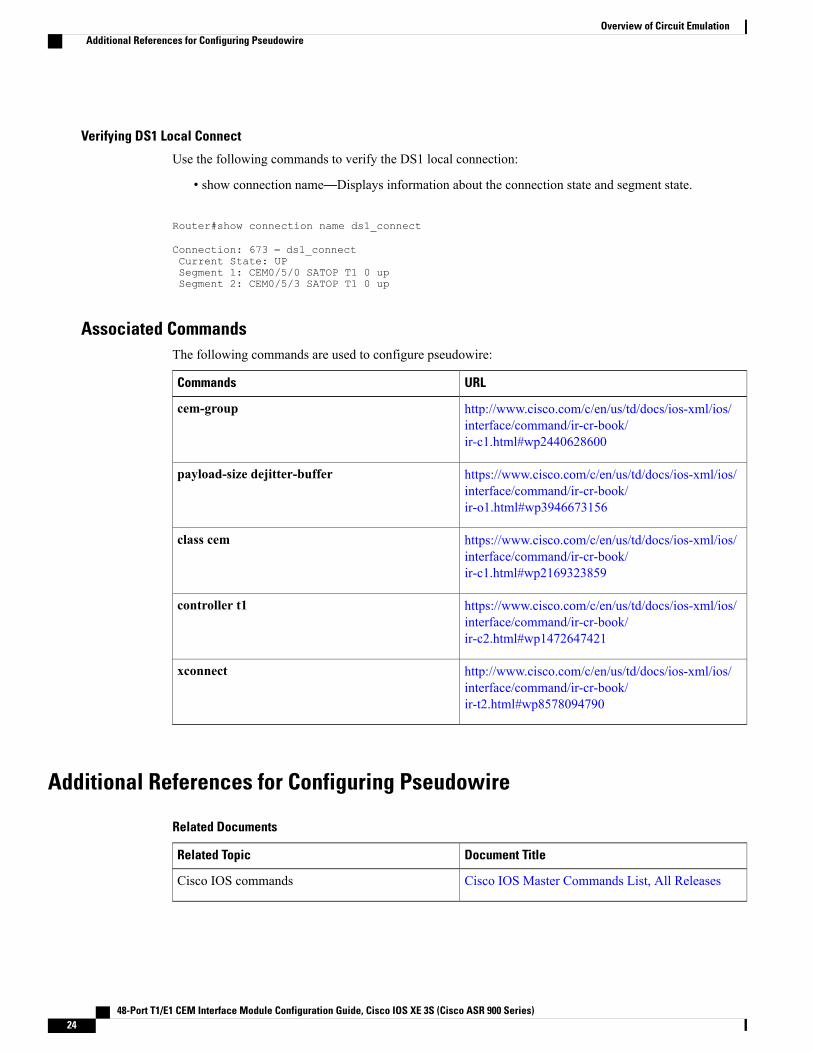
Verifying DS1 Local Connect
Use the following commands to verify the DS1 local connection:
• show connection name—Displays information about the connection state and segment state.
Router#show connection name ds1_connect
Connection: 673 – ds1_connectCurrent State: UPSegment 1: CEM0/5/0 SATOP T1 0 upSegment 2: CEM0/5/3 SATOP T1 0 up
Associated CommandsThe following commands are used to configure pseudowire:
URLCommands
http://www.cisco.com/c/en/us/td/docs/ios-xml/ios/interface/command/ir-cr-book/ir-c1.html#wp2440628600
cem-group
https://www.cisco.com/c/en/us/td/docs/ios-xml/ios/interface/command/ir-cr-book/ir-o1.html#wp3946673156
payload-size dejitter-buffer
https://www.cisco.com/c/en/us/td/docs/ios-xml/ios/interface/command/ir-cr-book/ir-c1.html#wp2169323859
class cem
https://www.cisco.com/c/en/us/td/docs/ios-xml/ios/interface/command/ir-cr-book/ir-c2.html#wp1472647421
controller t1
http://www.cisco.com/c/en/us/td/docs/ios-xml/ios/interface/command/ir-cr-book/ir-t2.html#wp8578094790
xconnect
Additional References for Configuring Pseudowire
Related Documents
Document TitleRelated Topic
Cisco IOS Master Commands List, All ReleasesCisco IOS commands
48-Port T1/E1 CEM Interface Module Configuration Guide, Cisco IOS XE 3S (Cisco ASR 900 Series)24
Overview of Circuit EmulationAdditional References for Configuring Pseudowire
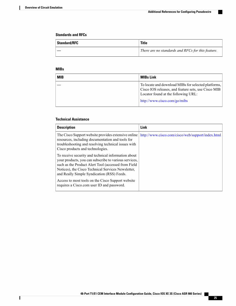
Standards and RFCs
TitleStandard/RFC
There are no standards and RFCs for this feature.—
MIBs
MIBs LinkMIB
To locate and downloadMIBs for selected platforms,Cisco IOS releases, and feature sets, use Cisco MIBLocator found at the following URL:
http://www.cisco.com/go/mibs
—
Technical Assistance
LinkDescription
http://www.cisco.com/cisco/web/support/index.htmlThe Cisco Support website provides extensive onlineresources, including documentation and tools fortroubleshooting and resolving technical issues withCisco products and technologies.
To receive security and technical information aboutyour products, you can subscribe to various services,such as the Product Alert Tool (accessed from FieldNotices), the Cisco Technical Services Newsletter,and Really Simple Syndication (RSS) Feeds.
Access to most tools on the Cisco Support websiterequires a Cisco.com user ID and password.
48-Port T1/E1 CEM Interface Module Configuration Guide, Cisco IOS XE 3S (Cisco ASR 900 Series) 25
Overview of Circuit EmulationAdditional References for Configuring Pseudowire

48-Port T1/E1 CEM Interface Module Configuration Guide, Cisco IOS XE 3S (Cisco ASR 900 Series)26
Overview of Circuit EmulationAdditional References for Configuring Pseudowire

C H A P T E R 3Alarm History
Alarm history or alarm persistence feature enables the maintenance of the history of the port and the pathalarms of 48-Port T1/E1 CEM Interface Module .
History of the port-level and path-level alarms are saved into a file and is retained for monitoring networkevents.
• Alarm History Restrictions, page 27
• Configuring Alarm History, page 28
• Verification of Alarm History Configuration, page 28
• Associated Commands, page 29
• Additional References for Alarm History, page 29
Alarm History RestrictionsThe following restrictions apply for the alarm history feature:
• Only port and path level alarm history or alarm persistency is supported.
• Persistence of T1/E1 alarms on a Channelized T3/E3 port is not supported.
• Two new files are created after each reboot.
• The primary and secondary log file are created during feature initialization. The primary log file saves10000 alarms. When the threshold of 10000 alarms in the primary log file is crossed, the subsequent10000 alarms are saved in the secondary log file. After crossing the threshold of 10000 alarms in thesecondary log file, the content of primary log file is cleared and is replaced with the subsequent alarms.
•When a primary file switches to a secondary file and vice versa, the following happens:
• An information level syslog message is displayed.
• An informatory message is written in the file where subsequent alarms are stored.
•When RSP switchover happens, the alarm history files are not copied to the new active RSP. Two newfiles are created in the new active RSP.
48-Port T1/E1 CEM Interface Module Configuration Guide, Cisco IOS XE 3S (Cisco ASR 900 Series) 27

•When you re-configure alarm history or alarm persistence feature, two new files are created.
Configuring Alarm HistoryThe configuration of alarm history helps in defining the periodicity or the interval at which the alarm entriesare saved in the designated file. To configure alarm history:enableconfigure terminalservice alarm persistency interval <20-600>end
When alarm history is configured, two log files are created in bootflash:tracelogs in the following format:<persistent_alarm[1/2][TIME_STAMP(DD_MMMM_YYYY_HH_MM_SSS)].log>
The syslog message is displayed as the following after configuration:*Jun 15 10:16:51.270: %ALARM_PERSISTENCY-6-ALARM_INFO_PROCESS_CREATE: createdmcprp_spa_persistence_logger process:292*Jun 15 10:16:51.270: %ALARM_PERSISTENCY-6-ALARM_CHUNK_INFO_CREATED: chunk pool creationfor alarm_info is successful*Jun 15 10:16:51.270: %ALARM_PERSISTENCY-6-ALARM_CHUNK_QUEUE_CREATED: chunk pool foralarm_queue is successful*Jun 15 10:16:51.283: %ALARM_PERSISTENCY-6-ALARM_INFO_FILE_CREATED: Successfully created/bootflash/tracelogs/persistent_alarm_1.15_June_2016_10_16__270.log fileRouter#*Jun 15 10:16:51.295: %ALARM_PERSISTENCY-6-ALARM_INFO_FILE_CREATED: Successfully created/bootflash/tracelogs/persistent_alarm_2.15_June_2016_10_16__270.log file*Jun 15 10:16:52.541: %SYS-5-CONFIG_I: Configured from console by consoleRouter#
Verification of Alarm History ConfigurationUse the show process | include persis command to verify the validity of the process.Router#show process | include persis292 Msi 13F0D4AC 0 49 010328/12000 0 mcprp_spa_persisRouter#
Verify the contents of the persistent alarm log files using the following commands:Router#dir bootflash:tracelogs/*persistent*Directory of bootflash:tracelogs/*persistent*394172 -rw- 1606 Jun 15 2016 07:50:39 +00:00persistent_alarm_1.15_June_2016_07_46__158.log394173 -rw- 6299 Jun 15 2016 07:50:38 +00:00persistent_alarm_2.15_June_2016_07_46__158.log6185086976 bytes total (4867022848 bytes free)Router#
Router#more bootflash:tracelogs/persistent_alarm_1.15_June_2016_07_46__158.logAt:15_June_2016_07_50__916 contents of persistent_alarm_2.15_June_2016_07_46__158.log arefull, so switched to this file*07:50:19.360 UTC Wed Jun 15 2016|SLOT_0 |BAY_3 |PORT_0 |2 |1 |6 |4|SONET_SDH_PATH_VT/TU_ALARM|MAJOR|VT_UNEQUIPPED|CLEARED*07:50:19.360 UTC Wed Jun 15 2016|SLOT_0 |BAY_3 |PORT_0 |2 |1 |6 |4|SONET_SDH_PATH_VT/TU_ALARM|MAJOR|VT_PATH_LOP|RAISED*07:50:19.360 UTC Wed Jun 15 2016|SLOT_0 |BAY_3 |PORT_0 |2 |1 |7 |1|SONET_SDH_PATH_VT/TU_ALARM|MAJOR|VT_UNEQUIPPED|CLEARED*07:50:19.360 UTC Wed Jun 15 2016|SLOT_0 |BAY_3 |PORT_0 |2 |1 |7 |1|SONET_SDH_PATH_VT/TU_ALARM|MAJOR|VT_PATH_LOP|RAISED*07:50:19.360 UTC Wed Jun 15 2016|SLOT_0 |BAY_3 |PORT_0 |2 |1 |7 |2|SONET_SDH_PATH_VT/TU_ALARM|MAJOR|VT_UNEQUIPPED|CLEARED*07:50:19.360 UTC Wed Jun 15 2016|SLOT_0 |BAY_3 |PORT_0 |2 |1 |7 |2|SONET_SDH_PATH_VT/TU_ALARM|MAJOR|VT_PATH_LOP|RAISED*07:50:19.360 UTC Wed Jun 15 2016|SLOT_0 |BAY_3 |PORT_0 |2 |1 |7 |3
48-Port T1/E1 CEM Interface Module Configuration Guide, Cisco IOS XE 3S (Cisco ASR 900 Series)28
Alarm HistoryConfiguring Alarm History

|SONET_SDH_PATH_VT/TU_ALARM|MAJOR|VT_UNEQUIPPED|CLEARED*07:50:19.361 UTC Wed Jun 15 2016|SLOT_0 |BAY_3 |PORT_0 |2 |1 |7 |3|SONET_SDH_PATH_VT/TU_ALARM|MAJOR|VT_PATH_LOP|RAISED*07:50:19.361 UTC Wed Jun 15 2016|SLOT_0 |BAY_3 |PORT_0 |2 |1 |7 |4|SONET_SDH_PATH_VT/TU_ALARM|MAJOR|VT_UNEQUIPPED|CLEARED*07:50:19.361 UTC Wed Jun 15 2016|SLOT_0 |BAY_3 |PORT_0 |2 |1 |7 |4|SONET_SDH_PATH_VT/TU_ALARM|MAJOR|VT_PATH_LOP|RAISED*07:50:23.333 UTC Wed Jun 15 2016|SLOT_0 |BAY_3 |PORT_0 |1 |1 |1 |1|SONET_SDH_PATH_VT/TU_ALARM|MAJOR|VT_UNEQUIPPED|CLEARED*07:50:27.335 UTC Wed Jun 15 2016|SLOT_0 |BAY_3 |PORT_0 |1 |1 |1 |1|SONET_SDH_PATH_VT/TU_PDH_DS1_ALARM|NA|DS1_AIS|CLEARED
Router#
Associated CommandsThe following commands are used to configure alarm history:
LinksCommands
http://www.cisco.com/c/en/us/td/docs/ios-xml/ios/interface/command/ir-cr-book/ir-s1.html#wp3501057143
service alarm persistency interval
http://www.cisco.com/c/en/us/td/docs/ios-xml/ios/interface/command/ir-cr-book/ir-s5.html#wp9298909580
show process | include persis
Additional References for Alarm HistoryRelated Documents
Document TitleRelated Topic
Cisco IOS Master Commands List, All ReleasesCisco IOS commands
Standards
TitleStandards
There are no standards for this feature.—
48-Port T1/E1 CEM Interface Module Configuration Guide, Cisco IOS XE 3S (Cisco ASR 900 Series) 29
Alarm HistoryAssociated Commands
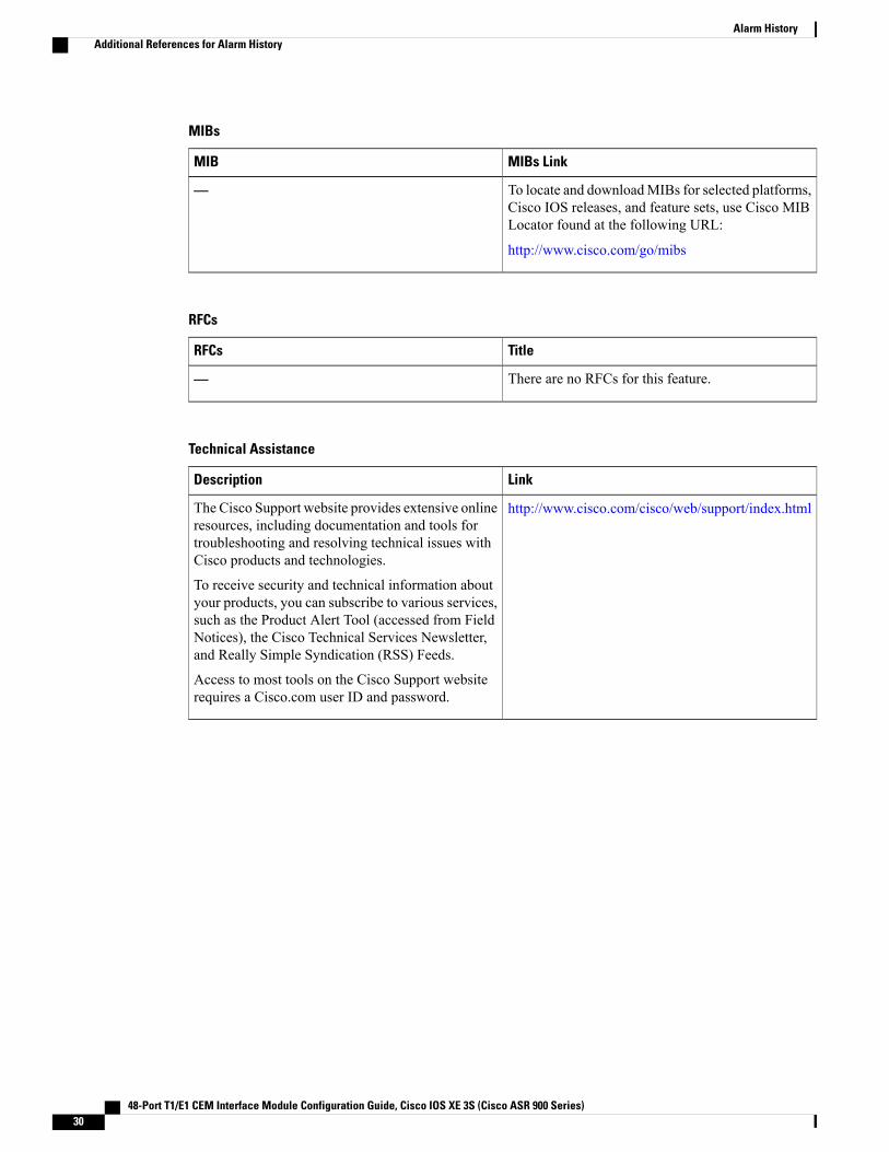
MIBs
MIBs LinkMIB
To locate and downloadMIBs for selected platforms,Cisco IOS releases, and feature sets, use Cisco MIBLocator found at the following URL:
http://www.cisco.com/go/mibs
—
RFCs
TitleRFCs
There are no RFCs for this feature.—
Technical Assistance
LinkDescription
http://www.cisco.com/cisco/web/support/index.htmlThe Cisco Support website provides extensive onlineresources, including documentation and tools fortroubleshooting and resolving technical issues withCisco products and technologies.
To receive security and technical information aboutyour products, you can subscribe to various services,such as the Product Alert Tool (accessed from FieldNotices), the Cisco Technical Services Newsletter,and Really Simple Syndication (RSS) Feeds.
Access to most tools on the Cisco Support websiterequires a Cisco.com user ID and password.
48-Port T1/E1 CEM Interface Module Configuration Guide, Cisco IOS XE 3S (Cisco ASR 900 Series)30
Alarm HistoryAdditional References for Alarm History

C H A P T E R 4Clock Recovery System for SAToP
TheClock Recovery System recovers the service clock usingAdaptive Clock Recovery (ACR) andDifferentialClock Recovery (DCR).
• Finding Feature Information, page 31
• Information About Clock Recovery, page 31
• Prerequisites for Clock Recovery, page 33
• Restrictions for Clock Recovery, page 33
• How to Configure ACR and DCR, page 33
• Associated Commands, page 36
• Additional References for Clock Recovery, page 37
Finding Feature InformationYour software release may not support all the features documented in this module. For the latest caveats andfeature information, see Bug Search Tool and the release notes for your platform and software release. Tofind information about the features documented in this module, and to see a list of the releases in which eachfeature is supported, see the feature information table.
Use Cisco Feature Navigator to find information about platform support and Cisco software image support.To access Cisco Feature Navigator, go to www.cisco.com/go/cfn. An account on Cisco.com is not required.
Information About Clock Recovery
Adaptive Clock Recovery (ACR)Adaptive Clock Recovery (ACR) is an averaging process that negates the effect of random packet delayvariation and captures the average rate of transmission of the original bit stream. ACR recovers the originalclock for a synchronous data stream from the actual payload of the data stream. In other words, a synchronous
48-Port T1/E1 CEM Interface Module Configuration Guide, Cisco IOS XE 3S (Cisco ASR 900 Series) 31

clock is derived from an asynchronous packet stream. ACR is a technique where the clock from the TDMdomain is mapped through the packet domain, but is most commonly used for Circuit Emulation (CEM).
Effective Cisco IOS XE Everest 16.5.1, ACR is supported on the 8-port T1/E1 interface module.
Differential Clock Recovery (DCR)Differential Clock Recovery (DCR) is another technique used for Circuit Emulation (CEM) to recover clocksbased on the difference between PE clocks. TDM clock frequency are tuned to receive differential timingmessages from the sending end to the receiving end. A traceable clock is used at each end, which ensures therecovered clock is not affected by packet transfer.
Benefits of Clock Recovery• Customer-edge devices (CEs) can have different clock from that of the Provide-edge devices (PEs).
• In CESoPSN, a slave clock is supported for clock redundancy.
48-Port T1/E1 CEM Interface Module Configuration Guide, Cisco IOS XE 3S (Cisco ASR 900 Series)32
Clock Recovery System for SAToPDifferential Clock Recovery (DCR)
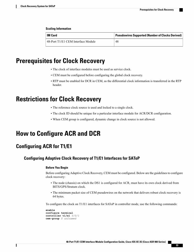
Scaling Information
Pseudowires Supported (Number of Clocks Derived)IM Card
4848-Port T1/E1 CEM Interface Module
Prerequisites for Clock Recovery• The clock of interface modules must be used as service clock.
• CEM must be configured before configuring the global clock recovery.
• RTP must be enabled for DCR in CEM, as the differential clock information is transferred in the RTPheader.
Restrictions for Clock Recovery• The reference clock source is used and locked to a single clock.
• The clock ID should be unique for a particular interface module for ACR/DCR configuration.
•When CEM group is configured, dynamic change in clock source is not allowed.
How to Configure ACR and DCR
Configuring ACR for T1/E1
Configuring Adaptive Clock Recovery of T1/E1 Interfaces for SAToP
Before You Begin
Before configuring Adaptive Clock Recovery, CEMmust be configured. Below are the guidelines to configureclock recovery:
• The node (chassis) on which the DS1 is configured for ACR, must have its own clock derived fromBITS/GPS/Stratum clock.
• The minimum packet size of CEM pseudowires on the network that delivers robust clock recovery is64 bytes.
To configure the clock on T1/E1 interfaces for SAToP in controller mode, use the following commands:
enableconfigure terminalcontroller t1/e1 0/0/1cem-group 0 unframed
48-Port T1/E1 CEM Interface Module Configuration Guide, Cisco IOS XE 3S (Cisco ASR 900 Series) 33
Clock Recovery System for SAToPPrerequisites for Clock Recovery

clock source recovered 1exit
To configure the clock recovery on T1/E1 interfaces in global configurationmode, use the following commands:
recovered-clock 0 0clock recovered 1 adaptive cem 1 0exit
The clock configuration on controller must be done before configuring the clock recovery on globalconfiguration mode.
Note
To remove the clock configuration in ACR and DCR, you must remove the recovery clock configuration inglobal configuration mode and then remove the controller configuration.
Verifying the Adaptive Clock Recovery Configuration of T1/E1 Interfaces for SAToP
Use the show recovered-clock command to verify the adaptive clock recovery of T1/E1 interfaces for SAToP:
Router# show recovered-clock
Recovered clock status for subslot 0/4--------------------------------------Clock Type Mode CEM Status Frequency Offset(ppb) Circuit-No
0 DS1 ADAPTIVE 0 ACQUIRED n/a 0 (Port)
Use the show running-config command to verify the configuration of adaptive clock of T1/E1 interfaces:
Router# show running-config | section 0/0/1controller T1/E1 0/0/1framing unframedclock source recovered 1linecode b8zscablelength long 0dbcem-group 0 unframed
interface CEM0/0/1no ip addresscem 0
Use the show running-config | section recovered-clock command to verify the recovery of adaptive clockof T1/E1 interfaces:
Router# show running-config | section recovered-clockrecovered-clock 0 0clock recovered 1 adaptive cem 1 0
Configuring DCR for T1/E1
Configuring Differential Clock Recovery of T1/E1 Interfaces for SAToP
Before You Begin
Before configuring Differential Clock Recovery, CEM must be configured. Below are the guidelines toconfigure Differential clock recovery:
48-Port T1/E1 CEM Interface Module Configuration Guide, Cisco IOS XE 3S (Cisco ASR 900 Series)34
Clock Recovery System for SAToPConfiguring DCR for T1/E1

• Before you start configuring DCR, RTP must be enabled on the CEM interface. The RTP is used tocarry the differential time.
• The minimum packet size of CEM pseudowires on the network that delivers robust clock recovery is64 bytes.
To configure the clock on T1/E1 interfaces for SAToP in controller mode, use the following commands:
enableconfigure terminalcontroller t1/e1 0/0/1cem-group 0 unframedclock source recovered 1exit
To configure RTP header on T1/E1 interfaces in global configuration mode, use the following commands:
interface cem 0/0/1cem 0rtp-present
To configure Differential clock recovery of T1/E1 interfaces, use the following commands in globalconfiguration mode:
recovered-clock 0 0clock recovered 1 differential cem 1 0exit
The clock configuration on controller must be done before configuring the clock recovery on globalconfiguration mode.
Note
Verifying the Differential Clock Recovery Configuration of T1/E1 Interfaces for SAToP
Use the show recovered-clock command to verify the differential clock recovery of T1/E1 interfaces forSAToP:
Router# show recovered-clock
Recovered clock status for subslot 0/4---------------------------------------Clock Type Mode CEM Status Frequency Offset(ppb) Circuit-No
0 DS1 DIFFERENTIAL 0 ACQUIRED n/a 0 (Port)
Use the show running-config | section command to verify the configuration of differential clock of T1/E1interfaces for SAToP:
Router# show running-config | section 0/0/1controller T1/E1 0/0/1framing unframedclock source recovered 1linecode b8zscablelength long 0dbcem-group 0 unframed
interface CEM 0/0/1no ip addresscem 0rtp-present
48-Port T1/E1 CEM Interface Module Configuration Guide, Cisco IOS XE 3S (Cisco ASR 900 Series) 35
Clock Recovery System for SAToPConfiguring DCR for T1/E1

Use the show running-config | section recovered-clock command to verify the recovery of differentialclock of T1/E1 interfaces:
Router# show running-config | section recovered-clockrecovered-clock 0 0clock recovered 1 differential cem 1 0
Configuring Network ClockTo configure a network clock, use the following commands:enableconfigure terminalcontroller E1/T1 0/5/0clock source linecem-group 0 unframedexitenableconfigure terminalnetwork-clock input-source 1 controller E1/T1 0/5/0exit
Verifying Network Clocking ConfigurationUse show run | sec network-cl command to verify the network clocking configuration.
network-clock synchronization automaticnetwork-clock synchronization mode QL-enablednetwork-clock input-source 1 controller E1 0/1/0network-clock wait-to-restore 10 globalrtr1#sh netw synchronizationSymbols: En - Enable, Dis - Disable, Adis - Admin Disable
NA - Not Applicable* - Synchronization source selected# - Synchronization source force selected& - Synchronization source manually switched
Automatic selection process : EnableEquipment Clock : 2048 (EEC-Option1)Clock Mode : QL-EnableESMC : EnabledSSM Option : 1T0 : E1 0/1/0Hold-off (global) : 300 msWait-to-restore (global) : 10 secTsm Delay : 180 msRevertive : No
Nominated Interfaces
Interface SigType Mode/QL Prio QL_IN ESMC Tx ESMC RxInternal NA NA/Dis 251 QL-SEC NA NA*E1 0/1/0 NA NA/Dis 1 QL-SEC NA NArtr1#
Associated CommandsThe commands used to configure adaptive clock recovery and differential clock recovery are:
48-Port T1/E1 CEM Interface Module Configuration Guide, Cisco IOS XE 3S (Cisco ASR 900 Series)36
Clock Recovery System for SAToPConfiguring Network Clock

URLCommands
http://www.cisco.com/c/en/us/td/docs/ios-xml/ios/interface/command/ir-cr-book/ir-c2.html#wp8894393830
clock recovered adaptive cem
http://www.cisco.com/c/en/us/td/docs/ios-xml/ios/interface/command/ir-cr-book/ir-c2.html#wp8894393830
clock recovered differential cem
http://www.cisco.com/c/en/us/td/docs/ios-xml/ios/interface/command/ir-cr-book/ir-c1.html#wp2440628600
cem-group
http://www.cisco.com/c/en/us/td/docs/ios-xml/ios/interface/command/ir-cr-book/ir-o1.html#wp8262293900
recovered-clock
http://www.cisco.com/c/en/us/td/docs/ios-xml/ios/interface/command/ir-cr-book/ir-c2.html#wp1472647421
controller t1/e1
http://www.cisco.com/c/en/us/td/docs/ios-xml/ios/interface/command/ir-cr-book/ir-c2.html#wp6081785140
clock-source
http://www.cisco.com/c/en/us/td/docs/ios-xml/ios/interface/command/ir-cr-book/ir-l2.html
network-clock input-source
Additional References for Clock RecoveryRelated Documents
Document TitleRelated Topic
Cisco IOS Master Commands List, All ReleasesCisco IOS commands
Standards and RFCs
TitleStandard/RFC
Timing and synchronization aspects in packetnetworks
ITU -T G.8261
48-Port T1/E1 CEM Interface Module Configuration Guide, Cisco IOS XE 3S (Cisco ASR 900 Series) 37
Clock Recovery System for SAToPAdditional References for Clock Recovery

MIBs
MIBs LinkMIB
To locate and downloadMIBs for selected platforms,Cisco IOS releases, and feature sets, use Cisco MIBLocator found at the following URL:
http://www.cisco.com/go/mibs
—
Technical Assistance
LinkDescription
http://www.cisco.com/cisco/web/support/index.htmlThe Cisco Support website provides extensive onlineresources, including documentation and tools fortroubleshooting and resolving technical issues withCisco products and technologies.
To receive security and technical information aboutyour products, you can subscribe to various services,such as the Product Alert Tool (accessed from FieldNotices), the Cisco Technical Services Newsletter,and Really Simple Syndication (RSS) Feeds.
Access to most tools on the Cisco Support websiterequires a Cisco.com user ID and password.
48-Port T1/E1 CEM Interface Module Configuration Guide, Cisco IOS XE 3S (Cisco ASR 900 Series)38
Clock Recovery System for SAToPAdditional References for Clock Recovery

I N D E X
C
Circuit Emulation Service over Packet-Switched Network(CESoPSN 4, 5, 9, 21
48-Port T1/E1 CEM Interface Module Configuration Guide, Cisco IOS XE 3S (Cisco ASR 900 Series) IN-1

48-Port T1/E1 CEM Interface Module Configuration Guide, Cisco IOS XE 3S (Cisco ASR 900 Series)IN-2
Index