48 ieee/asme transactions on mechatronics, vol. 15, …...48 ieee/asme transactions on mechatronics,...
TRANSCRIPT

48 IEEE/ASME TRANSACTIONS ON MECHATRONICS, VOL. 15, NO. 1, FEBRUARY 2010
Full Sheet Control Using Steerable NipsRene Sanchez, Member, IEEE, Roberto Horowitz, Senior Member, IEEE, and Masayoshi Tomizuka, Fellow, IEEE
Abstract—This paper describes the mechatronics design, proto-type testing, and control of a steerable nips component for paperpath mechanisms in high-speed color printers and photocopiers.When placed upstream from the image transfer station along thepaper path, this device precisely controls the longitudinal, lateral,and skew directions of papers sheets, as they arrive to the imagetransfer station. The paper also presents a complete kinematic anddynamic analysis of the paper sheet steering mechanism, which isvalidated by experimental results. It is shown that the dynamicsof a sheet under the control of the steerable nips mechanism arenonlinear and subject to nonholonomic constraints. A feedbacklinearization control strategy that includes dynamic surface con-trol is developed and implemented to control the sheet’s positionand angular orientation under the condition that the sheet’s speedin the longitudinal direction remains positive at all times. Experi-mental results verify that the steerable nips mechanism under theproposed feedback linearization control strategy is able to meet orexceed all design performance requirements for deployment as acomponent of an actual printer paper path control mechanism.
Index Terms—Nonholonomic, nonlinear control, paper sheetcontrol, state feedback linearization.
I. INTRODUCTION
S TATE-OF-THE-ART paper path control requires the sheetsto be accurately positioned as they arrive to the image trans-
fer station. This includes correction for longitudinal, lateral, andangular errors. To accomplish this task, current machines havea registration station at the end of the paper path and before theimage transfer station, which must correct for lateral and skewerrors and deliver the sheet to the image transfer station on timeand with a constant longitudinal velocity. However, most state-of-the-art registration devices cannot correct for errors at highspeeds, whereas others mark the paper since they rely on highcontact point forces to move the sheet laterally. In this paper,we present the mechatronics design, control, and experimentalverification of an innovative device, known as the steerable nipsmechanism [11] that permits a swifter correction of sheet lat-eral, longitudinal, and angular errors without marking the sheet.A prototype of this device was designed and built in the Depart-ment of Mechanical Engineering of the University of Californiaat Berkeley (UCB). The sheet actuation mechanism in this de-vice consists of two rollers, which are free to rotate parallel
Manuscript received March 25, 2008; revised December 27, 2008. Firstpublished March 27, 2009; current version published November 18, 2009.Recommended by Technical Editor M. Benbouzid. This work was supported inpart by the National Science Foundation under Grant CMS 0301719 and in partby Xerox Corporation.
R. Sanchez is with Nikon Research Corporation of America, Belmont,CA 94002-4107 USA (e-mail: [email protected]).
R. Horowitz and M. Tomizuka are with the Department of Mechanical Engi-neering, University of California at Berkeley, Berkeley, CA 94720-1740 USA(e-mail: [email protected]; [email protected]).
Color versions of one or more of the figures in this paper are available onlineat http://ieeexplore.ieee.org.
Digital Object Identifier 10.1109/TMECH.2009.2015293
and perpendicular to the sheet, and will henceforth be referredto as “steerable nips.” A freely rotating ball is spring-loadedagainst each of the steerable nips, providing a normal forcethat creates the friction force needed to propel the sheet throughrolling, while minimizing the contact area between the steerablenip and sheet, hence decreasing the possibility of marking thesheet. By controlling the steering angle and spinning velocityof each of the two nips, it is possible to control the longitudinalposition, lateral position, and angular orientation of the sheet ina somewhat analogous manner to steering a two-wheel robot;cf., [2] and [27]–[29]. However, unlike the two-wheel robotsteering control problem, the sheet control under the steerablenips mechanism proposed in this paper has an additional de-gree of freedom, since the paper sheet can buckle, whereas thepavement does not. As will be explained in subsequent sec-tions, the buckling of the paper makes it possible to linearizethe system dynamics through feedback, whereas feedback lin-earization cannot be achieved in the two-wheel robot steeringproblem. The control system for the steerable nips mechanismmust be designed so the paper is neither folded nor stretched tooseverely to prevent the paper from tearing or having skid marksfrom the nips.
Prior recent work in the area of sheet control in a printer paperpath has primarily focused on the design of control architec-tures and control algorithms for coordinating multiple actuatedsections of the paper path, in order to correct for longitudinalinterspacing errors among sheets, and synchronize the arrivalof a sheet to the image transfer station with its correspond-ing image, with respect to both time and longitudinal veloc-ity [1], [3]–[6], [12]–[16], [18], [26]. However, none of theseworks address that issue of the simultaneous correction of papersheet longitudinal, lateral, and angular positioning errors, whichis the focus of this paper. Prior works that address this issue aremore scarce, cf., [25], and is primarily in the form of patentdisclosures. The description of the steerable nips mechanism inthis paper, as well as its kinematic analysis, was first presentedin [21]. However, because the fabrication of the steerable nipsprototype was not completed, a simplified dynamic analysis ofmechanism was only presented in [21], which did not includeactuators’ dynamics, as well as a significantly simplified versionof the feedback control scheme presented in this paper and somesimulation results. A hybrid automata-based control strategy forthe model described in [21] is presented in [22], which has fourfinite states among which the control system switches during thetrajectory tracking process. It is shown in [22] that by using ahybrid automata, it is possible to drive the paper from rest to anyother position. A more complete dynamic model of the steer-able nips mechanism in this paper is presented in [20], whichincluded actuators’ dynamics, as well as experimental results,some of which are included in this paper. Recently, a controlstrategy is presented in [7] for an underactuated steerable nips
1083-4435/$26.00 © 2009 IEEE
SANCHEZ et al.: FULL SHEET CONTROL USING STEERABLE NIPS 49
mechanism for printer sheet registration devices that is similarto the device presented in this paper. However, since the mecha-nism in [7] has one less degree of freedom than the mechanismpresented in this paper and no sheet buckling nor actuators’dynamics is included in the control system design model, thecontrol problem in [7] resembles more that of the steering atwo-wheel robot, precluding the use of feedback linearization,and the resulting control strategy is significantly different fromthe one presented in this paper.
The objective of the steerable nips mechanism is to controlthe motion of a sheet of paper on an horizontal plane, from thetime instant when the leading edge of the sheet enters in contactwith the nips until the time instant when the trailing edge of thesheet losses contact with the nips, in order to reduce longitudi-nal, lateral, and angular position tracking errors to acceptablelevels before the sheet enters the image registration station. Thecontrol strategy presented in this paper uses linearization bystate feedback [23] and a backstepping technique similar to dy-namic surface control [24], and considers a realistic steerablenip mechanism model that accounts for small amounts of sheetbuckling and includes actuator dynamics. Simulation and exper-imental results are in close agreement and show that by usingthe proposed control strategy, the steerable nips mechanism cancorrect for large initial sheet tracking errors, which exceed in-dustry specifications, and attain sheet tracking errors when thesheet enters the registration station that are well below industryrequirements without damaging the sheet.
Section II describes in detail the design process of some ofthe important components of the experimental setup. In orderto derive a realistic model of the controlled plant, the dynamicmodels for each of the actuators were derived and validatedwith experimental data, which is described in Section III. InSection IV, we derive the kinematic model, and in Section V,we derive the overall dynamic model of the steerable nips mech-anism. The control strategy developed to control paper positionand orientation of a sheet is presented in Section VI. The modeland experimental results are presented in Section VII. Finally,conclusions and some comments regarding the design, controlstrategies, and experimental results are stated in Section VIII.
II. EXPERIMENTAL SETUP
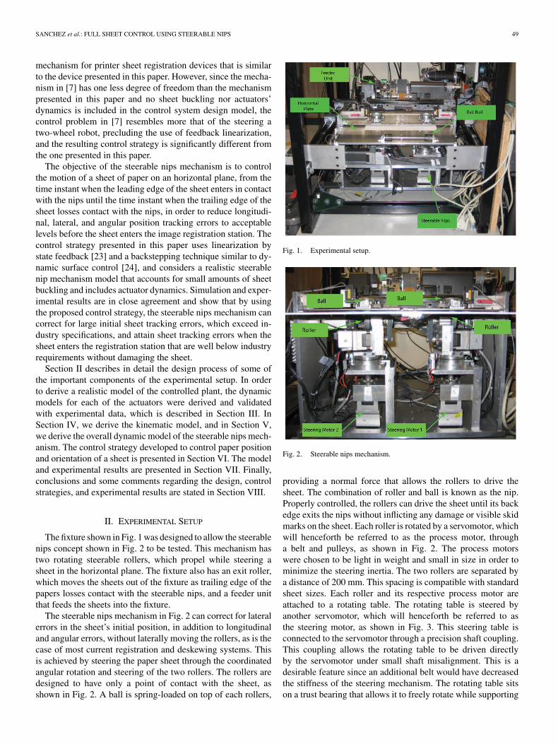
The fixture shown in Fig. 1 was designed to allow the steerablenips concept shown in Fig. 2 to be tested. This mechanism hastwo rotating steerable rollers, which propel while steering asheet in the horizontal plane. The fixture also has an exit roller,which moves the sheets out of the fixture as trailing edge of thepapers losses contact with the steerable nips, and a feeder unitthat feeds the sheets into the fixture.
The steerable nips mechanism in Fig. 2 can correct for lateralerrors in the sheet’s initial position, in addition to longitudinaland angular errors, without laterally moving the rollers, as is thecase of most current registration and deskewing systems. Thisis achieved by steering the paper sheet through the coordinatedangular rotation and steering of the two rollers. The rollers aredesigned to have only a point of contact with the sheet, asshown in Fig. 2. A ball is spring-loaded on top of each rollers,
Fig. 1. Experimental setup.
Fig. 2. Steerable nips mechanism.
providing a normal force that allows the rollers to drive thesheet. The combination of roller and ball is known as the nip.Properly controlled, the rollers can drive the sheet until its backedge exits the nips without inflicting any damage or visible skidmarks on the sheet. Each roller is rotated by a servomotor, whichwill henceforth be referred to as the process motor, througha belt and pulleys, as shown in Fig. 2. The process motorswere chosen to be light in weight and small in size in order tominimize the steering inertia. The two rollers are separated bya distance of 200 mm. This spacing is compatible with standardsheet sizes. Each roller and its respective process motor areattached to a rotating table. The rotating table is steered byanother servomotor, which will henceforth be referred to asthe steering motor, as shown in Fig. 3. This steering table isconnected to the servomotor through a precision shaft coupling.This coupling allows the rotating table to be driven directlyby the servomotor under small shaft misalignment. This is adesirable feature since an additional belt would have decreasedthe stiffness of the steering mechanism. The rotating table sitson a trust bearing that allows it to freely rotate while supporting

50 IEEE/ASME TRANSACTIONS ON MECHATRONICS, VOL. 15, NO. 1, FEBRUARY 2010
Fig. 3. Process direction actuator and steering motor mechanism.
TABLE IPROCESS ACTUATOR VARIABLES AND EXPERIMENTALLY DETERMINED
MODEL PARAMETERS
its weight. There are also two ball bearings that prevent therotating table from moving axially.
III. ACTUATOR DYNAMICS
There are four actuators in the steerable nips mechanism.Two of the actuators rotate each of the rollers and the othertwo steer them. In this section, we describe the dynamic modelderivation, reduction, and validation for each of the actuators ofthe experimental fixture.
A. Process Dynamics
The process actuators rotate the two rollers and each consistsof a dc servomotor, which drives a roller through a timing belt,as shown in Fig. 3. A fifth-order linear state-space model ofthis actuator was derived, which accounted for the stiffness ofthe timing belt and inductance of the dc motor. The parametersof the model were determined through experimental frequencyresponse tests and are listed in Table I.
Fig. 4 plots the experimental frequency response of the trans-fer function between the voltage input and the roller angular
Fig. 4. Experimental and modeled frequency response of the process actuator.
rotation output of the process actuator, as well as the corre-sponding frequency response of the derived fifth-order model.As shown in the figure, the model frequency response closelymatches experimental data at frequencies below 100 Hz.
The fifth-order process actuator model was reduced to asecond-order model by neglecting the inductance of the dc mo-tor and assuming that the timing belt connecting the two pulleysof the actuator is very stiff. The resulting transfer function be-tween the input voltage and the roller angular rotation outputis
θr + αp θr = βpu (1)
where
αp =Bfr + (r2
3/r24 )Bfb + (Bfm + (K2
t /R))(r22/r2
1 )Jr + (r2
3/r24 )Jb + (r2
2/r21 )Jm
and
βp =(r1/r2)(Kt/R)
Jr + (r23/r2
4 )Jb + (r22/r2
1 )Jm.
The frequency response of the simplified model (1) can beseen in Fig. 5. It is shown that the magnitude of the second-ordermodel closely matches the fifth-order model in the frequencyrange shown. As expected, the phase of the reduced-order modeldiverges from the fifth-order model at high frequencies.
B. Steering Dynamics
The steering actuator consists of a dc servomotor that ro-tates a table, as shown in Fig. 3. This table holds the processactuator and is connected to the motor through a coupling. Athird-order linear state-space model of this actuator was derived,which accounted for inductance of the dc motor. The parametersof the model were determined through experimental frequencyresponse tests and are listed in Table II.
Fig. 6 plots the experimental frequency response of the trans-fer function between the voltage input and the steering angularrotation, as well as the corresponding frequency response of the

SANCHEZ et al.: FULL SHEET CONTROL USING STEERABLE NIPS 51
Fig. 5. Frequency responses of the process motor high-order and reduced-order models.
TABLE IISTEERING ACTUATOR VARIABLES AND EXPERIMENTALLY DETERMINED
PARAMETER VALUES
derived third-order model. As shown in the figure, the modelfrequency response closely matches experimental data at fre-quencies below 40 Hz.
The mismatch between the modeled and experimental re-sults for frequencies higher than 40 Hz can be attributed to lowsignal-to-noise ratio. The system was exited with white noiseand the excitation level did not produce a sufficiently large dis-placement at high frequency to overcome the encoder accuracy.The estimated values for the parameters of the steering actua-tors are also shown in Table II. As in the case of the processactuators, the dynamic model of the steering mechanism canbe reduced by assuming that the inductance of the motor isnegligible (L(di/dt) ≈ 0). The resulting second-order transferfunction is given by
φ + αsφ = βsu (2)
where
αs =(Bf + (K2
t /R))Jt
and βs =Kt
JtR.
The frequency responses of the second-order and third-ordermodels are shown in Fig. 7.
Fig. 6. Experimental and modeled steering actuator frequency response.
Fig. 7. High-order and reduced-order steering actuator frequency response.
IV. KINEMATIC ANALYSIS
The steerable nips mechanism with a sheet is illustrated inFigs. 8 and 9. The steerable nips propel a sheet on a flat surface.Fig. 8 represents the initial position of the sheet, when it firstmakes contact with the nips. Fig. 9 shows the sheet while it isbeing driven by the nips. The left corner of the sheet, point C, isused as a reference point for tracking. Note that even if the paperbuckles, point C will remain on the flat surface since buckingoccurs only between points 1 and 2 where the sheet contacts thenips.
A. Kinematic Analysis Assumption
A key modeling assumption in the kinematic analysis thatfollows is that, even under buckling, the sheet remains transver-sally stiff and it rotates as a rigid body under the action of the

52 IEEE/ASME TRANSACTIONS ON MECHATRONICS, VOL. 15, NO. 1, FEBRUARY 2010
Fig. 8. Sheet entering the steerable nips system.
Fig. 9. Steerable nips with sheet buckle.
Fig. 10. System coordinates.
steerable nips. This assumption is illustrated in Fig. 9, whereany line perpendicular to the line that connects contact points1 and 2 drawn along the buckled surface remains horizontal.Numerous experimental results confirmed the validity of thisassumption to within possible measurement resolution.
B. Notation
Fig. 10 shows a schematic representation of the kinematicvariables for the steerable nips system. This system has twoindependent steering wheels located at points 1 and 2. Thesesteerable wheels are separated by a distance 2b. Three coordi-nate frames are defined to describe the position and orientationof the paper sheet: a fixed global coordinate system denotedby (if , j
f, kf ), and two local frames (i1 , j1
, k1) and (i2 , j2, k2)
attached to wheels 1 and 2, respectively. The generalized coor-dinates of the system are (x, y, φ, δ, θ1 , θ2 , φ1 , φ2). Generalizedcoordinates x and y will be used to represent the lateral andlongitudinal position of the leading right corner of the sheet(point C), respectively. Coordinate φ represents the angular (orskew) rotation of the sheet and −δ represents the amount ofbuckle experienced by the sheet, which we assume to only take
place along the line that connects points 1 and 2. The angularpositions of wheel 1 in the directions parallel and perpendicularto the sheet are denoted as θ1 and φ1 , respectively. Likewise,θ2 and φ2 describe the angular position of wheel 2 parallel andperpendicular to the sheet.
C. Velocity Analysis
The velocities of the paper at points 1 and 2 in global coordi-nates are
v1 = (x + φy)if + (y − φ(x + b))jf− δif (3)
v2 = (x + φy)if + (y + φ(−x + b))jf
(4)
where δ is the rate of change of the sheet buckle (or stretch),which is assumed to only take place along the direction of theline that connects point 1 and 2 (along the if unit vector). Notethat a negative δ implies that the sheet has buckled while apositive δ implies that the sheet has stretched. Invoking thenonslip condition, v1 and v2 can also be written in terms of theangular speed of the wheels in the local coordinate frames
v1 = −r1 θ1j1(5)
v2 = −r2 θ2j2(6)
where r1 and r2 are the radius of wheels 1 and 2, respectively.Four constraint equations are obtained by writing (5) and (6)
in terms of the global coordinates and equating them to (3) and(4)
v1 = −r1 θ1 [− sin φ1if + cos φ1jf]
= (x + φy − δ)if + (y − φ(x + b))jf
(7)
v2 = −r2 θ2 [− sin φ2if + cos φ2jf]
= (x + φy)if + (y − φ(x − b))jf. (8)
These equations result in four nonholonomic constraints
x + φ y − δ = r1 sin φ1 θ1 (9)
y − φ(x + b) = −r1 cos φ1 θ1 (10)
x + φ y = r2 sin φ2 θ2 (11)
y − φ(x − b) = −r2 cos φ2 θ1 . (12)
Defining the generalized coordinate p = [x y φ δ θ1 θ2φ1 φ2 ]T , the constraints can be written in Pfaffian form [17] as
A(p)p = 0 (13)
where A(p) is the 4 × 8 matrix defined as
A(p)
=
1 0 y −1 −r1 sin φ1 0 0 0
0 1 −(x+ b) 0 r1 cos φ1 0 0 0
1 0 y 0 0 −r2 sinφ2 0 0
0 1 −(x− b) 0 0 r2 cos φ2 0 0
.

SANCHEZ et al.: FULL SHEET CONTROL USING STEERABLE NIPS 53
D. Kinematic Equations
The kinematic model represents the relation between the mov-ing parts of the system, when they comply with the nonholo-nomic constraints describe earlier. As detailed in [17], this isgiven by a basis of the right null space of the constraints ai(p),which will be denoted by gj (p) ∈ R
n , j = 1, . . . , n − k = m.By construction, this basis satisfies
ai(p)gj (p) = 0, i = 1, . . . , k, j = 1, . . . , n − k, p ∈ Rn
and all allowable trajectories of the system can thus be writtenas the possible solutions of the system
p = g1(p)u1 + · · · + gm (p)um (14)
i.e., p(t) is a feasible trajectory of the system if and only if p(t)satisfies (14) for a choice of control u(t) ∈ R
m .For our system, this basis is easily obtained and the solution
can be written as follows:
x = −yr1
2bcos φ1 θ1 +
(yr2
2bcos φ2 + r2 sin φ2
)θ2 (15)
y =(
(x + b)r1
2bcos φ1 − r1 cos φ1
)θ1 −
(x + b)r2
2bcos φ2 θ2
(16)
φ =12b
(r1 cos φ1 θ1 − r2 cos φ2 θ2) (17)
δ = r2 sin φ2 θ2 − r1 sinφ1 θ1 (18)
which constitute the kinematic model of our system. Note that(15)–(18) can be succinctly written as follows:
y = G(y, η)η (19)
where the output
y = [x y φ δ ]T
is the generalized coordinate vector of the paper sheet, withelements given, respectively, by the lateral and longitudinal co-ordinates x and y for the sheet’s leading edge right corner C(see Fig. 10), the sheet angular rotation φ, and the buckle δ, and
η = [ θ1 θ2 φ1 φ2 ]T
is the input vector formed by the nips’ rotor angular speeds andsteering angles.
E. Sheet Motion Sensing and Kinematic Model ExperimentalValidation
An array of optical sensors, located along the longitudinaldirection in the midpoint between the two rollers, as shown inFig. 11, was used to detect the leading edge of the sheet. Threelaser sensors, two of which are located on the right side of thesheet at locations (x,−ds) and (x, 0), respectively, and one islocated on the left size of the sheet at location (−x, 0), as shownin Fig. 11, were used to measure the lateral deviation of thesheet edge relative to the sensor location (e.g., s1 and s2 arezero if the right-hand sheet edge is on top of both sensors). Theamount of buckle −δ was determined from the readings s2 ands3 of the two laser sensors located on opposite sides of the sheet,
Fig. 11. Sheet position from optical and laser sensors.
while the angular position of the sheet φ was determined fromreadings s1 and s2 of the two laser sensors on the right side ofthe sheet. They are, respectively, given by
δ = s2 − s3 φ = tan−1(
s1 − s2
ds
)(20)
where ds is the longitudinal distance between the two lasersensors 1 and 2, as shown in Fig. 11.
The position of point C(x, y) on the right side of the leadingedge of the sheet was determined every time the leading edge ofthe sheet went over one of the optical sensors. The longitudinalposition of each sensor that is being crossed is denoted by y, thenthe coordinates y and x of the point C(x, y) are, respectively,given by
y = y + (x − y tan φ + s2) sin φ cos φ
x = x − y tan φ (21)
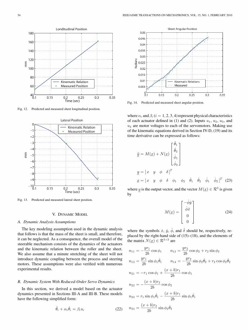
where 2x is the lateral distance between laser sensors 2 and 3 (seeFig. 11). The kinematic state model equations given by (19) werevalidated using the following procedure: first, a sheet of paperwas fed into and controlled by the steerable nips mechanismuntil it exited, while all sensor data were collected and stored.Second, the initial generalized coordinate vector of the papersheet y(0) was set to the values either directly measured orcomputed from (20) and (21) at the instant when the leadingedge of the sheet went over the first optical longitudinal sensor.Subsequently, (19) were numerically integrated using as inputsthe measured roller angular speed and steering angle of each nip.Finally, the numerically integrated sheet longitudinal, lateral,and angular positions [y(t), x(t), φ(t)] were plotted along withactual values computed from (20) and (21) at the instanceswhen the leading edge of the sheet went over one of the opticallongitudinal sensors. Typical results are shown in Figs. 12–14.
Note that there is a close match between the measured andpredicted data in spite of the fact that the edges of paper sheetsare not perfectly straight, and the data were contaminated bysensor and quantization noise. The angular velocities and steer-ing angles used for the experimental validation of the kinematicequations were chosen in order not to induce appreciable buckle.Whatever buckle values were obtained from measurements and(20) were within the range of error attributed to the fact that thesheets are not all exactly of the same length and their edges arenot parallel to each other.
54 IEEE/ASME TRANSACTIONS ON MECHATRONICS, VOL. 15, NO. 1, FEBRUARY 2010
Fig. 12. Predicted and measured sheet longitudinal position.
Fig. 13. Predicted and measured lateral sheet position.
V. DYNAMIC MODEL
A. Dynamic Analysis Assumptions
The key modeling assumption used in the dynamic analysisthat follows is that the mass of the sheet is small, and therefore,it can be neglected. As a consequence, the overall model of thesteerable mechanism consists of the dynamics of the actuatorsand the kinematic relation between the roller and the sheet.We also assume that a minute stretching of the sheet will notintroduce dynamic coupling between the process and steeringmotors. These assumptions were also verified with numerousexperimental results.
B. Dynamic System With Reduced-Order Servo Dynamics
In this section, we derived a model based on the actuatordynamics presented in Sections III-A and III-B. These modelshave the following simplified form:
θi + αiθi = βiui (22)
Fig. 14. Predicted and measured sheet angular position.
where αi and βi (i = 1, 2, 3, 4) represent physical characteristicsof each actuator defined in (1) and (2). Inputs u1 , u2 , u3 , andu4 are motor voltages to each of the servomotors. Making useof the kinematic equations derived in Section IV-D, (19) and itstime derivative can be expressed as follows:
y = M(x) + N(x)
θ1
θ2
φ1
φ2
y = [x y φ δ ]T
x = [x y φ δ φ1 φ2 θ1 θ2 φ1 φ2 ]T (23)
where y is the output vector, and the vector M(x) ∈ R3 is givenby
M(x) =
−φy
φx
00
(24)
where the symbols x, y, φ, and δ should be, respectively, re-placed by the right-hand side of (15)–(18), and the elements ofthe matrix N(x) ∈ R3×3 are
n11 = −yr1
2bcos φ1 n12 =
yr2
2bcos φ2 + r2 sin φ2
n13 =yr1
2bsinφ1 θ1 n14 = −yr2
2bsin φ2 θ2 + r2 cos φ2 θ2
n21 = −r1 cos φ1 +(x + b)r1
2bcos φ1
n22 = − (x + b)r2
2bcos φ2
n23 = r1 sinφ1 θ1 −(x + b)r1
2bsin φ1 θ1
n24 =(x + b)r2
2bsin φ2 θ2

SANCHEZ et al.: FULL SHEET CONTROL USING STEERABLE NIPS 55
n31 =r1
2bcos φ1 n32 = −r2
2bcos φ2
n33 = −r1
2bsin φ1 θ1 n34 =
r2
2bsin φ2 θ2
n41 = −r1 sinφ1 n42 = r2 sinφ2
n43 = −r1 cos φ1 θ1 n44 = r2 cos φ2 θ2 .
It should be emphasized that a necessary and sufficient con-dition for the matrix N(x) to remain nonsingular is that thelongitudinal speed y should remain positive.
The overall dynamic system model is given by
y = M(x) + N(x)
θ1
θ2
φ1
φ2
,
θ1 + α1 θ1 = β1u1
θ2 + α2 θ2 = β2u2
φ1 + α3 φ1 = β3u3
φ2 + α4 φ2 = β4u4 .
(25)
VI. NONLINEAR CONTROL STRATEGY
The control objective in this paper is to control a sheet on thehorizontal plane from an initial state with nonzero longitudinalvelocity to a final state also with nonzero longitudinal velocity.The control strategy presented in this section assumes a realisticsecond-order model for all actuators, as derived and validatedin Section V-B. The control strategy developed for this sys-tem is also dynamic and uses concepts of linearization by statefeedback [23] and a backstepping technique similar to dynamicsurface control [24]. The desired sheet trajectories lateral andlongitudinal coordinates x and y for the sheet’s leading edgeright corner C, the sheet angular rotation φ, and the buckle δ aregiven by
xd(t) = xd(t) = xd(t) = 0
yd(t) = αt, yd(t) = α, yd(t) = 0
φd(t) = φd(t) = φd(t) = 0
δd(t) = −c1 , δd(t) = δd(t) = 0 (26)
for t = [0, T ], where α and T are, respectively, the desiredlongitudinal velocity of the sheet and time at which the sheetmust leave the steerable nips mechanism. The amount of buckleis c1 . The block diagram of the proposed control strategy isshown in Fig. 15. The control law is given by
θ1d
θ2d
φ1d
φ2d
= N(x)−1
xd + (K1 + λ1) ˙x + λ1K1 x
yd + (K2 + λ2) ˙y + λ2K2 y
φd + (K3 + λ3)˙φ + λ3K3 φ
δd + (K4 + λ4)˙δ + λ4K4 δ
− M(x)
(27)
C1(s) =kp1(s+ γ1)(s+ γ2)
s2 C2(s)=kp2(s+ γ3)(s+ γ4)
s2
C3(s) =ks1(s + η1)s(s + η2)
C4(s) =ks2(s + η3)s(s + η4)
. (28)
Fig. 15. Control system block diagram.
Equation (27), which is schematically depicted in Fig. 15by the block CF BL , linearizes through feedback the kinemat-ics and generates the desired angular accelerations and desiredsteering velocities for each of the rollers. These desired valuesare then integrated to obtain reference trajectories, which aretracked by local inner linear controllers given by (28) and rep-resented by the blocks Ci(s), i = 1, 2, 3, 4, in Fig. 15, whereηi and γi (i = 1, 2, 3, 4) are positive coefficients. The actuators’process dynamics are represented by the blocks P1(s), i = 1, 2,in Fig. 15 while the steering dynamics are represented by theblocks Pi(s), i = 3, 4.
A formal convergence analysis of this control strategy isprovided in [9], [10], and [19]. Moreover, they also providea systematic methodology to tune the control system so that,given a specified maximum nominal longitudinal speed α anda minimum travel time T = α/L, where L is the length of thesheet, control gains can be determined so that the magnitudeof tracking errors is guaranteed to be attenuated, from specifiedmaximum initial values, to final values that are within specifiedallowable values.
In the control strategy in (27) and (28), feedback lineariza-tion is used only to linearize the kinematics of the system, whileinternal loops are used to locally control the actuator’s positionsand velocities. Through extensive simulation and experimentalresults, such as those presented in Section VII, we have foundthat this control strategy performs robustly to parameter anddynamic uncertainty in the actuators. This robustness can beattributed to the fact the feedback linearization portion of thecontroller does not depend on the actuator dynamics. In contrast,we have found [8] that control strategies that are based on directoutput feedback linearization plus dynamic extension [23] ofthe overall plant given (25) do not perform well, under iden-tical conditions, due to parameter and dynamic uncertainty inthe actuators. A comprehensive robustness analysis is also pre-sented in [8], which shows that the control strategy based onkinematic feedback linearization with actuator internal loops issignificantly more robust to parameter and dynamic uncertaintyin the actuators than the control strategy that is based on thedirect output feedback linearization plus dynamic extension ofthe overall dynamics.
VII. SIMULATION AND EXPERIMENTAL RESULTS
Simulated and experimental results were obtained for a sheetwith initial conditions, as shown in Table III. The values for

56 IEEE/ASME TRANSACTIONS ON MECHATRONICS, VOL. 15, NO. 1, FEBRUARY 2010
TABLE IIIINITIAL EXPERIMENTAL AND SIMULATED SHEET ERRORS
TABLE IVCONTROL VARIABLES
Fig. 16. (a) Sheet lateral and longitudinal errors. (b) Sheet angular positionand sheet buckle.
Fig. 17. (a) Roller angular velocity. (b) Roller steering angle.
the aforementioned control parameters are shown in Table IV.Each of the control gains is the combination of all system gainssuch as gains of the amplifier, conversion factor from radiansto encoder pulses, etc. The sheet was steered from this initialcondition to a desired longitudinal, lateral, and angular position.In addition, the sheet was kept with a small amount of buckle toavoid stretching the sheet. Fig. 16(a) shows the sheet longitudi-nal and lateral errors, and Fig. 16(b) shows the angular positionand amount of paper buckle. The errors were reduced in the timeallowed, less than 0.382 s. This time is dependent on the sheet ve-locity, the amount of skew error, the gap between lateral sensors,and the sizes of a sheet. For example, for an A4 sheet (194.6 ×279.4 mm), traveling at the velocity of 0.5 m/s with a maximumangular error of 0.025 rad and a sensor gap of 21.3 mm resultsin an allowable time of 0.382 s for correction for all errors.The final errors are within the requirements: less than ±1.3 mmin the lateral direction, ±1.6 mm in the process direction, and±3.5 mrad of angular error. Experimental and simulated resultsof sheet errors in Fig. 16(a) and (b) show some discrepancies.These discrepancies can be attributed to sensor noise and slipbetween the ball and the sheet. The rollers’ angular velocitiesand steering angular positions are shown in Fig. 17(a) and (b).
SANCHEZ et al.: FULL SHEET CONTROL USING STEERABLE NIPS 57
As it was expected, the initial and final angular velocities areequivalent to the sheet’s nominal longitudinal velocity once theerrors have been corrected. The steering angular position of eachroller is close to zero once the sheet’s errors have been corrected.
Current sensing equipment limit the control precision at highspeeds. Laser sensors noise level increases at high speeds de-creasing the precision of sensors.
VIII. CONCLUSION
This paper presented an innovative mechanism to improvepaper handling performance in a printer paper handling system,when it is placed before the image registration station. Thismechanism uses steerable nips to control the motion of a sheetof paper on a horizontal plane, from the time instant when theleading edge of the sheet enters in contact with the nips until thetime instant when the trailing edge of the sheet losses contactwith the nips and enters the registration station, in order toreduce longitudinal, lateral, and angular position tracking errorsto acceptable levels.
A prototype of this device was constructed and tested.Kinematic and dynamic models of the steerable nips mecha-nism were derived under the assumptions that the mass of thesheet can be neglected and that the paper sheet remains suf-ficiently stiff under minute levels of buckling to sustain rigidbody rotation, and were validated with experimental data. Acontrol strategy was presented in this paper comprised of a non-linear outer feedback linearization loop and inner dynamic sur-face control loops around each of the actuators. The outer looplinearizes the paper sheet kinematics under the steerable nipsmechanism action and generates desired rotating speeds andsteering angles for each of the two steerable nips. These refer-ence trajectories are tracked by the four inner dynamic surfacecontrol feedback loops. Simulation and experimental results arein close agreement and show that by using the proposed controlstrategy, the steerable nips mechanism can correct for large ini-tial sheet tracking errors, which exceed industry specifications,and attain sheet tracking errors that are below industry require-ments when the sheet enters the registration station, withoutdamaging or marking the sheet. Small discrepancies betweenthe experimental and simulation results were attributed to sen-sor noise, irregularities in the edge of the paper, and slight modelparameter mismatches, particularly among the damping ratiosof the actuators dynamics.
REFERENCES
[1] B. Bukkems, R. van de Molengraft, M. Heemels, N. van de Wouw, andM. Steinbuch, “A piecewise linear approach towards sheet control in aprinter paper path,” in Proc. Amer. Control Conf., 2006, pp. 1315–1320.
[2] G. Campion, B. d’Andrea Novel, and G. Bastin, “Controllability and statefeedback stabilisability of nonholonomic mechanical systems,” in Proc.Adv. Robot Control: Proc. Int. Workshop Nonlinear Adaptive Control:Issues Robot., Grenoble, France, Nov. 1990, pp. 106–124.
[3] C. Cloet, M. Krucinski, R. Horowitz, and M. Tomizuka, “A hybrid controlscheme for a copier paperpath,” in Proc. 1999 Amer. Control Conf., SanDiego, CA, Jun., pp. 2114–2118.
[4] C. Cloet, M. Krucinski, R. Horowitz, and M. Tomizuka, “Intersheet spac-ing control and controllability of a copier paperpath,” in Proc. 1998 IEEEConf. Control Appl., Trieste, Italy, Sep., pp. 726–730.
[5] C. Cloet, M. Tomizuka, and R. Horowitz, “Design requirements and refer-ence trajectory generation for a copier paperpath,” presented at the Conf.Adv. Intell. Mechatronics, Como, Italy, Jul. 2001.
[6] C. Clote, “A mechatronics approach to copier paperpath design,” Ph.D.dissertation, Univ. California, Berkeley, 2001.
[7] J. G. Elliot and R. F. Gans, “Closed-loop control of an underactuated sheetregistration device using feedback linearization and gain scheduling,”IEEE Trans. Control Syst. Technol., vol. 16, no. 4, pp. 589–599, Jul. 2008.
[8] E. Ergueta, R. Seifried, and R. Horowitz, “A robust approach to dy-namic feedback linearization for steerable nips mechanism,” presentedat the 2008 ASME Dyn. Syst. Control Conf., Ann Arbor, MI, Oct.2008.
[9] E. Ergueta, R. Sanchez, R. Horowitz, and M. Tomizuka, “Convergenceanalysis of a steerable nips mechanism for full sheet control in printingdevices,” ASME J. Dyn. Syst. Meas. Control, 2007, to be published.
[10] E. Ergueta, R. Sanchez, R. Horowitz, and M. Tomizuka, “Full sheet controlthrough the use of steer-able nips,” presented at the 2007 ASME IMECE,Seattle, WA, Nov. 2007, Paper IMECE2007-41279.
[11] N. Y. Hwang and S. S. Penfield, “Sheet registration and deskewing sys-tem with independent drives and steering,” U.S. Patent 6 634 521, Oct.2003.
[12] J. J. T. H. de Best, B. H. M. Bukkems, M. J. G. van de Molengraft,W. P. M. H. Heemels, and M. Steinbuch, “Robust control of piecewiselinear systems: A case study in sheet flow control,” Control Eng. Pract.,vol. 16, no. 8, pp. 991–1003, Aug. 2008.
[13] M. Krucinski, “Feedback control of photocopying machinery,” Ph.D. dis-sertation, Univ. California, Berkeley, 2000.
[14] M. Krucinski, C. Cloet, R. Horowitz, and M. Tomizuka, “Asynchronousobserver for a copier paperpath,” in Proc. 37th IEEE Conf. Decis. Control,Dec. 1998, vol. 3, pp. 2611–2612.
[15] M. Krucinski, C. Cloet, R. Horowitz, and M. Tomizuka, “Interobject spac-ing control and controllability of a manufacturing transportation system,”in Proc. 1999 Amer. Control Conf., Jun., vol. 2, pp. 1259–1265, SessionWA03-4.
[16] M. Krucinski, C. Cloet, R. Horowitz, and M. Tomizuka, “A mechatronicsapproach to copier paperpath control,” presented at the 1st IFAC Conf.Mechatronics Syst., Darmstadt, Germany, Sep. 2000.
[17] R. M. Murray, Z. Li, and S. S. Sastry, A Mathematical Introduction toRobotic Manipulation. Boca Raton, FL: CRC Press, 1993.
[18] S. Rai and W. Jackson, “A hybrid hierarchical control architecture forpaper transport systems,” in Proc. 37th IEEE Conf. Decis. Control, Tampa,FL, Dec. 1998, pp. 4294–4295.
[19] R. Sanchez, “Nonlinear control strategies for a steerable nips mechanism,”Ph.D. dissertation, Univ. California, Berkeley, 2006.
[20] R. Sanchez, E. Ergueta, B. Fine, R. Horowitz, M. Tomizuka, andM. Krucinski, “A mechatronic approach to full sheet control using steer-able nips,” presented at the 4th IFAC-Symp. Mechatron. Syst., Heidelberg,Germany, Sep. 2006.
[21] R. Sanchez, R. Horowitz, and M. Tomizuka, “Paper sheet control usingsteerable nips,” in Proc. 2004 Amer. Control Conf., Boston, MA, Jun.30–Jul. 2, pp. 482–487.
[22] R. Sanchez, R. Horowitz, M. Tomizuka, and S. N. Simic, “Full papersheet control using hybrid automata,” in Proc. 2004 Hybrid Syst.: Comput.Control, Philadelphia, PA, Mar., pp. 523–538.
[23] S. S. Sastry, Nonlinear Systems : Analysis, Stability, and Control. NewYork: Springer-Verlag, 1999.
[24] D. Swaroop, J. C. Gerdes, P. P. Yip, and J. K. Hedrick, “Dynamic surfacecontrol of nonlinear systems,” in Proc. Amer. Control Conf., Albuquerque,NM, Jun.1997, vol. 5, pp. 3028–3034.
[25] N. Tanaka, H. Fukumoto, K. Arimoto, and Y. Iwashita, “Skew correc-tion mechanism for thermal transfer type color printers,” in Proc. Int.Conf. Micromechatronics Inf. Precis. Equipment, Tokyo, Japan, Jul. 1997,pp. 635–638.
[26] P. Tunestal and M. Krucinski, “Hybrid control of a manufacturing transportsystem,” in Proc. 1997 IEEE Conf. Decis. Control, San Diego, CA, Dec.1997, pp. 84–89, Session ID WA03–4.
[27] D. Wang and G. Xu, “Full-state tracking and internal dynamics of non-holonomic wheeled mobile robots,” IEEE/ASME Trans. Mechatronics,vol. 8, no. 2, pp. 203–214, Jun. 2003.
[28] Y. Xu and S. K.-W. Au, “Stabilization and path following of a single wheelrobot,” IEEE/ASME Trans. Mechatronics, vol. 9, no. 2, pp. 407–419, Jun.2004.
[29] X. Yun and N. Sarkar, “Dynamic feedback control of vehicles with twosteerable wheels,” in Proc. 1996 IEEE Int. Conf. Robot. Autom., 1996,pp. 3105–3110.
58 IEEE/ASME TRANSACTIONS ON MECHATRONICS, VOL. 15, NO. 1, FEBRUARY 2010
Rene Sanchez (M’09) was born in Gualaceo,Ecuador, in 1970. He received the B.S. and M.S.degrees in mechanical engineering from RensselaerPolytechnic Institute, Troy, NY, in 1993 and 1995, re-spectively, and the Ph.D. degree from the Universityof California, Berkeley, in 2006.
From 1995 to 2000, he was with the Xerox Re-search Center. Since 2006, he has been with NikonResearch Corporation of America, Belmont, CA. Hiscurrent research interests include nonlinear, learning,motion, and adaptive control related to robotics, pre-
cision movement, and manufacturing.Dr. Sanchez is a member of the American Society of Mechanical Engineers
(ASME).
Roberto Horowitz (M’89–SM’02) was born inCaracas, Venezuela, in 1955. He received the B.S.degree (with highest honors) and the Ph.D. degree inmechanical engineering from the University of Cali-fornia, Berkeley, in 1978 and 1983, respectively.
In 1982, he joined the Department of Me-chanical Engineering, University of California,Berkeley, where he is currently a Professor. His cur-rent research interests include the areas of adaptive,learning, nonlinear, and optimal control, with appli-cations to microelectromechanical systems (MEMS),
computer disk file systems, robotics, mechatronics, and intelligent vehicle andhighway systems (IVHSs).
Prof. Horowitz is a member of the American Society of Mechanical Engi-neers (ASME).
Masayoshi Tomizuka (M’86–SM’95–F’97) wasborn in Tokyo, Japan, in 1946. He received the B.S.and M.S. degrees in mechanical engineering fromKeio University, Tokyo, and the Ph.D. degree in me-chanical engineering from Massachusetts Institute ofTechnology, Cambridge, in 1974.
Since 1974, he has been with the University ofCalifornia, Berkeley, where he is currently the Cheryland John Neerhout, Jr., Distinguished ProfessorshipChair. He teaches courses in dynamic systems andcontrols. His current research interests include opti-
mal and adaptive control, digital control, signal processing, motion control, andcontrol problems related to robotics, machining, manufacturing, informationstorage devices, and vehicles. He was a consultant to various organizations,including General Electric, General Motors, and United Technologies.
Dr. Tomizuka was the Editor-in-Chief of the IEEE/ASME TRANSACTIONS
ON MECHATRONICS from 1997 to 1999. From 1998 to 1999, he was the Presi-dent of the American Automatic Control Council (AACC). From 2002 to 2004,he was the Program Director of the Dynamic Systems and Control Programin the Civil and Mechanical Systems Division, National Science Foundation.He is a Fellow of the ASME and the Society of Manufacturing Engineers. Hereceived the Charles Russ Richards Memorial Award from ASME in 1997, theRufus Oldenburger Medal from ASME in 2002, and the John R. RaggaziniAward from AACC in 2006. From 1988 to 1993, he was the Technical Editorof the American Society of Mechanical Engineers (ASME) Journal of DynamicSystems, Measurement and Control (J-DSMC).