4.5 pipelining - computer science - college of staten islandzhangs/csc446/lec14.pdf · 4.5...
TRANSCRIPT
85
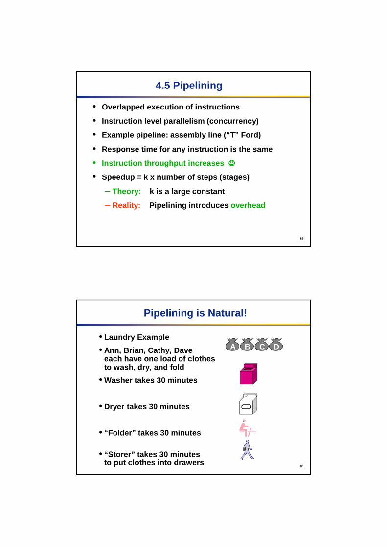
4.5 Pipelining
• Overlapped execution of instructions
• Instruction level parallelism (concurrency)
• Example pipeline: assembly line (“T” Ford)
• Response time for any instruction is the same
• Instruction throughput increases ☺☺☺☺
• Speedup = k x number of steps (stages)
– Theory: k is a large constant
– Reality: Pipelining introduces overhead
86
Pipelining is Natural!
• Laundry Example
• Ann, Brian, Cathy, Dave each have one load of clothes to wash, dry, and fold
• Washer takes 30 minutes
• Dryer takes 30 minutes
• “Folder” takes 30 minutes
• “Storer” takes 30 minutesto put clothes into drawers
A B C D

87
Sequential Laundry
• Sequential laundry takes 8 hours for 4 loads
• If they learned pipelining, how long would laundry take?
30Task
Order
B
C
D
ATime
30 30 3030 30 3030 30 30 3030 30 30 3030
6 PM 7 8 9 10 11 12 1 2 AM
88
Pipelined Laundry: Start work ASAP
• Pipelined laundry takes 3.5 hours for 4 loads!
Task
Order
12 2 AM6 PM 7 8 9 10 11 1
Time
B
C
D
A3030 30 3030 30 30

89
Pipelining Lessons• Pipelining doesn’t help
latency of single task, it helps throughput of entire workload
• Multiple tasks operating simultaneously using different resources
• Potential speedup = Number pipe stages
• Pipeline rate limited by slowest pipeline stage
• Unbalanced lengths of pipe stages reduces speedup
• Time to “ fill ” pipeline and time to “ drain ” it reduces speedup
• Stall for Dependences
6 PM 7 8 9
Time
B
C
D
A3030 30 3030 30 30
Task
Order
90
Five-stages of multi-cycle DP

91
The Five Stages of the Load Instruction
• Ifetch: Instruction Fetch
–Fetch the instruction from the Instruction Memory
• Reg/Dec: Registers Fetch and Instruction Decode
• Exec: Calculate the memory address
• Mem: Read the data from the Data Memory
• Wr: Write the data back to the register file
Cycle 1 Cycle 2 Cycle 3 Cycle 4 Cycle 5
Ifetch Reg/Dec Exec Mem WrLoad
92
Pipelined Execution
• On a processor multiple instructions are in various stages at the same time.
• Assume each instruction takes five cycles
IFetch Dcd Exec Mem WB
IFetch Dcd Exec Mem WB
IFetch Dcd Exec Mem WB
IFetch Dcd Exec Mem WB
IFetch Dcd Exec Mem WB
IFetch Dcd Exec Mem WBProgram Flow
Time
93
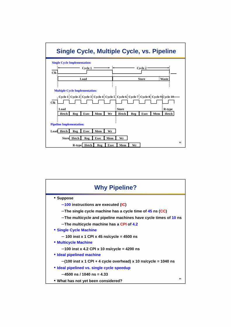
Single Cycle, Multiple Cycle, vs. Pipeline
Clk
Cycle 1
Multiple Cycle Implementation:
Ifetch Reg Exec Mem Wr
Cycle 2 Cycle 3 Cycle 4 Cycle 5 Cycle 6 Cycle 7 Cycle 8 Cycle 9Cycle 10
Load Ifetch Reg Exec Mem Wr
Ifetch Reg Exec Mem
Load Store
Pipeline Implementation:
Ifetch Reg Exec Mem WrStore
Clk
Single Cycle Implementation:
Load Store Waste
Ifetch
R-type
Ifetch Reg Exec Mem WrR-type
Cycle 1 Cycle 2
94
Why Pipeline?
• Suppose
–100 instructions are executed ( IC)
–The single cycle machine has a cycle time of 45 ns (CC)
–The multicycle and pipeline machines have cycle tim es of 10 ns
–The multicycle machine has a CPI of 4.2
• Single Cycle Machine
– 100 inst x 1 CPI x 45 ns/cycle = 4500 ns
• Multicycle Machine
–100 inst x 4.2 CPI x 10 ns/cycle = 4200 ns
• Ideal pipelined machine
–(100 inst x 1 CPI + 4 cycle overhead) x 10 ns/cycle = 1040 ns
• Ideal pipelined vs. single cycle speedup
–4500 ns / 1040 ns = 4.33
• What has not yet been considered?

95
Graphically Representing Pipelines
• Can help with answering questions like:
–How many cycles does it take to execute this code?
–What is the ALU doing during cycle 4?
–Are two instructions trying to use the same resourc e at the same time?
Instr.
Time (clock cycles)
Inst 0
Inst 1
ALUIm Reg Dm Reg
ALUIm Reg Dm Reg
96
Why Pipeline? Because the resources are there!
Instr.
Order
Time (clock cycles)
Inst 0
Inst 1
Inst 2
Inst 4
Inst 3
ALUIm Reg Dm Reg
ALUIm Reg Dm Reg
ALUIm Reg Dm Reg
ALUIm Reg Dm Reg
ALUIm Reg Dm Reg

97
Can pipelining get us into trouble?
• Yes: Pipeline Hazards
–structural hazards : attempt to use the same resource two different ways at the same time
• Two instructions use the memory at the same time
–data hazards : attempt to use item before it is ready
• instruction depends on result of prior instruction still in the pipeline
–control hazards : attempt to make a decision before condition is evaluated (branch instructions)
• Can always resolve hazards by waiting
–pipeline control must detect the hazard
–take action (or delay action) to resolve hazards
98
Structural Hazard 1: Single Memory
IM = DM => Read same memory twice in one clock cycle
I$
Load
Instr 1
Instr 2
Instr 3
Instr 4
ALUI$ Reg D$ Reg
ALUI$ Reg D$ Reg
ALUI$ Reg D$ Reg
ALUReg D$ Reg
ALUI$ Reg D$ Reg
Instr.
Order
Time (clock cycles)
99
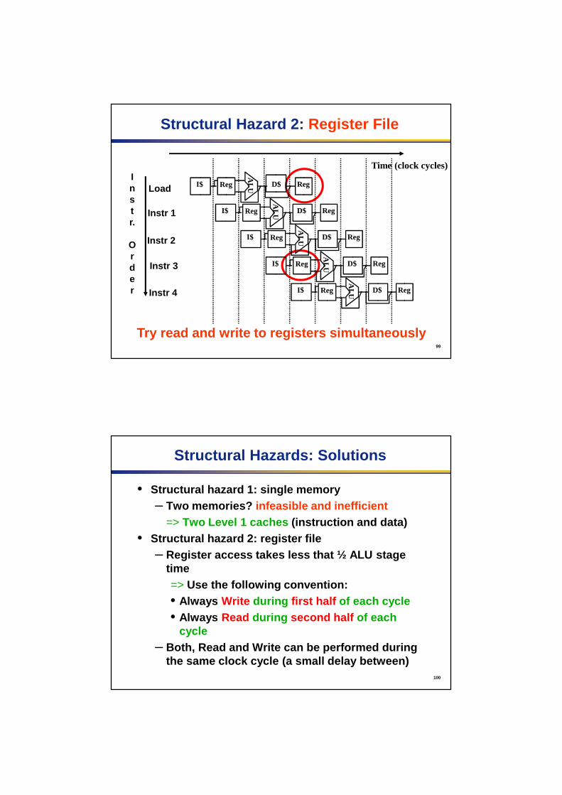
Structural Hazard 2: Register File
Try read and write to registers simultaneously
I$
Load
Instr 1
Instr 2
Instr 3
Instr 4
ALUI$ Reg D$ Reg
ALUI$ Reg D$ Reg
ALUI$ Reg D$ Reg
ALUReg D$ Reg
ALUI$ Reg D$ Reg
Instr.
Order
Time (clock cycles)
100
Structural Hazards: Solutions
• Structural hazard 1: single memory– Two memories? infeasible and inefficient
=> Two Level 1 caches (instruction and data) • Structural hazard 2: register file
– Register access takes less that ½ ALU stage time=> Use the following convention:• Always Write during first half of each cycle• Always Read during second half of each
cycle– Both, Read and Write can be performed during
the same clock cycle (a small delay between)

101
Control Hazard: Branch Instr. (1/2)
• Branch decision-making hardware in ALU stage
– Two more instructions after the branch will always be fetched, whether or not the branch is taken
• Desired functionality of a branch
– if we do not take the branch, don’t waste any time and continue executing normally
– if we take the branch, don’t execute any instructions after the branch, just go to the desired label
102
Control Hazard: Branch Instr. (2/2)
• Initial Solution : Stall until decision is made
– Insert “no-op” instructions: those that accomplish nothing, just take time
– Drawback: branches take 3 clock cycles each (assuming comparator is put in ALU stage)
L1: ADD R2, R2, #2 IF ID EX MEM WB
SUB R3, R1, #3 IF ID EX MEM WB
BEQ R5, R4, L1 IF ID EX MEM WB
ADD R2, R2, #2 S S IF ID EX MEM
S = stall

103
Branch Prediction
• Longer pipelines can’t readily determine branch outcome early
– Stall penalty becomes unacceptable
• Predict outcome of branch
– Only stall if prediction is wrong
• In MIPS pipeline
– Can predict branches not taken
– Fetch instruction after branch, with no delay
104
MIPS with Predict Not Taken
Prediction correct
Prediction incorrect

105
More-Realistic Branch Prediction
• Static branch prediction
– Based on typical branch behavior
– Example: loop and if-statement branches
• Predict backward branches taken
• Predict forward branches not taken
• Dynamic branch prediction
– Hardware measures actual branch behavior
• e.g., record recent history of each branch
– Assume future behavior will continue the trend
• When wrong, stall while re-fetching, and update his tory
106
Data Hazard
add r1 ,r2,r3
sub r4, r1 ,r3
and r6, r1 ,r7
or r8, r1 ,r9
xor r10, r1 ,r11
• Instruction depends on result of prior instruction still in the pipeline
• Problem: r1 cannot be read by other instructions before it is written by the add.

107
• Dependencies backwards in time are hazards
Data Hazard on r1:
Instr.
Order
Time (clock cycles) 1 2 3 4 5 6 7 8
add r1,r2,r3
sub r4, r1,r3
and r6, r1,r7
or r8, r1,r9
xor r10, r1,r11
IF ID/RF EX MEM WBALUIm Reg Dm Reg
ALUIm Reg Dm Reg
ALUIm Reg Dm Reg
Im
ALUReg Dm Reg
ALUIm Reg Dm Reg
108
Data hazard timing
add r1,r2,r3 IF ID EX MEM WB
sub r4,r1,r3 IF S S ID EX MEM WB
and r6,r1,r7 IF ID EX MEM
or r8,r1,r9 IF ID EX
S = stall
How to delete “ Stalls ”?

109
• “ Forward” result from one stage to another
• “or” OK if define read/write properly
Data Hazard Solution:
Instr.
Order
Time (clock cycles)
add r1,r2,r3
sub r4, r1,r3
and r6, r1,r7
or r8, r1,r9
xor r10, r1,r11
IF ID/RF EX MEM WBALUIm Reg Dm Reg
ALUIm Reg Dm Reg
ALUIm Reg Dm Reg
Im
ALUReg Dm Reg
ALUIm Reg Dm Reg
110
Data hazard timing
add r1,r2,r3 IF ID EX MEM WB
sub r4,r1,r3 IF S S ID EX MEM WB
and r6,r1,r7 IF ID EX MEM
or r8,r1,r9 IF ID EX
Without forwarding
add r1,r2,r3 IF ID EX MEM WB
sub r4,r1,r3 IF ID EX MEM WB
and r6,r1,r7 IF ID EX MEM WB
or r8,r1,r9 IF ID EX MEM WB
With forwarding

111
• Dependencies backwards in time are hazards
•Can’t solve with forwarding: • Must delay/stall instruction dependent on loads
Forwarding (or Bypassing): What about Loads
Time (clock cycles)
lw r1,0(r2)
sub r4, r1,r3
IF ID/RF EX MEM WBALUIm Reg Dm Reg
ALUIm Reg Dm Reg
112
Data hazard requiring stalls
LD R1, 0(R2) IF ID EX MEM WB
SUB R4, R1, R5 IF Stall stall ID EX MEM WB
AND R6, R1, R7 IF ID EX MEM WB
OR R8, R1, R9 IF ID EX MEM WB
LD R1, 0(R2) IF ID EX MEM WB
SUB R4, R1, R5 IF ID stall EX MEM WB
AND R6, R1, R7 IF stall ID EX MEM WB
OR R8, R1, R9 stall IF ID EX MEM WB
Without forwarding
With forwarding

113
MIPS Pipelined Datapath§4.6 P
ipelined Datapath and C
ontrol
WB
MEM
Right-to-left flow leads to hazards
114
Pipeline registers
• Need registers between stages
– To hold information produced in previous cycle
115
Pipeline Operation
• Cycle-by-cycle flow of instructions through the pipelined datapath
– “Single-clock-cycle” pipeline diagram
• Shows pipeline usage in a single cycle
• Highlight resources used
– c.f. “multi-clock-cycle” diagram
• Graph of operation over time
• We’ll look at “single-clock-cycle” diagrams for load & store
116
IF for Load, Store, …

117
ID for Load, Store, …
118
EX for Load

119
MEM for Load
120
WB for Load

121
EX for Store
122
MEM for Store

123
WB for Store
124
Multi-Cycle Pipeline Diagram
• Form showing resource usage

125
Multi-Cycle Pipeline Diagram
• Traditional form
126
Single-Cycle Pipeline Diagram
• State of pipeline in a given cycle