4.5 assessment of motors n
TRANSCRIPT

4.5 ENERGY PERFORMANCE ASSESSMENT OF MOTORS / VARIABLE SPEED DRIVES

Motor efficiency vs loading

Performance Terms and Definitions
Efficiency :The efficiency of the motor is given by
Where Pout – Output power of the motor Pin – Input power of the motor PLoss – Losses occurring in motor
Motor Loading :
Motor Loading % = Actual operating load of the motor Rated capacity of the motor

No Load TestThe motor is run at rated voltage and frequency without any shaft load. Input power, current, frequency and voltage are noted. The no load P.F. is quite low and hence low PF watt meters are required. From the input power, stator I2R losses under no load are subtracted to give the sum of Friction and Windage (F&W) and core losses. To separate core and F & W losses, test is repeated at variable voltages.It is worthwhile plotting no-load input kW versus Voltage; the intercept is F & W kW loss component.
F&W and core losses = No load power (watts) – (No load current)2 Stator resistance
Field Tests for Determining Efficiency

Stator and Rotor I2R Losses :The resistance must be corrected to the operating temperature. For modern motors, the operating temperature is likely to be in the range of 1000C to 1200C and necessary correction should be made. Correction to 750C may be inaccurate. The correction factor is given as follows :
where, t1 = ambient temperature, oC & t2 =- operating temperature, oC.
The rotor resistance can be determined from locked rotor test at reduced frequency, but rotor I2R losses are measured from measurement of rotor slip.
Rotor I2R losses = Slip (Stator Input – Stator I2R Losses – Core Loss)
Accurate measurement of slip is possible by stroboscope or non-contact type tachometer. Slip also must be corrected to operating temperature.
1
2
1
2
t 235 t 235
RR

Stray Load Losses
These losses are difficult to measure with any accuracy. IEEE Standard 112 gives a complicated method, which is rarely used on shop floor. IS and IEC standards take a fixed value as 0.5 % of output. It must be remarked that actual value of stray losses is likely to be more. IEEE – 112 specifies values from 0.9 % to 1.8 %.
Motor Rating Stray Losses
1 – 125 HP 1.8 %
125 – 500 HP 1.5 %
501 – 2499 HP 1.2 %
2500 and above 0.9 %

Points for Users It must be clear that accurate determination of efficiency is very difficult. The same motor tested by different methods and by same methods by different manufacturers can give a difference of 2 %. Estimation of efficiency in the field can be summarized as follows:
1. Measure stator resistance and correct to operating temperature. From rated current value, I2R losses are calculated.
2. From rated speed and output, rotor I2R losses are calculated3. From no load test, core and F & W losses are determined
for stray loss

Example
Motor Specifications
Collect the name plate details

Conduct No load test Data
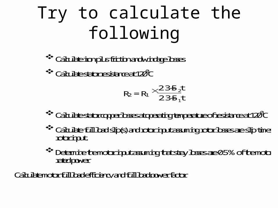
Try to calculate the following
Calculate iron plus friction and windage losses
Calculate stator resistance at 1200C
R2 = R1 1
2
t235 t235
Calculate stator copper losses at operating temperature of resistance at 1200C
Calculate full load slip(s) and rotor input assuming rotor losses are slip times rotor input.
Determine the motor input assuming that stray losses are 0.5 % of the motor rated power
Calculate motor full load efficiency and full load power factor

Solution
For three windings at no load

(operating temp)


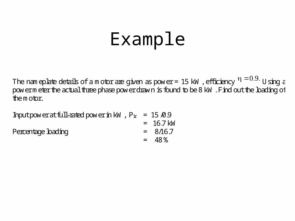
Example The nameplate details of a motor are given as power = 15 kW, efficiency Using a power meter the actual three phase power drawn is found to be 8 kW. Find out the loading of the motor. Input power at full-rated power in kW, Pir = 15 /0.9 = 16.7 kW Percentage loading = 8/16.7 = 48 %

By Line Current Measurements
T h e l i n e c u r r e n t l o a d e s t i m a t i o n m e t h o d i s u s e d w h e n i n p u t p o w e r c a n n o t b e m e a s u r e d a n d o n l y a m p e r a g e m e a s u r e m e n t s a r e p o s s i b l e . T h e a m p e r a g e d r a w o f a m o t o r v a r i e s a p p r o x i m a t e l y l i n e a r l y w i t h r e s p e c t t o l o a d , d o w n t o a b o u t 7 5 % o f f u l l l o a d . B e l o w t h e 7 5 % l o a d p o i n t , p o w e r f a c t o r d e g r a d e s a n d t h e a m p e r a g e c u r v e b e c o m e s i n c r e a s i n g l y n o n - l i n e a r . I n t h e l o w l o a d r e g i o n , c u r r e n t m e a s u r e m e n t s a r e n o t a u s e f u l i n d i c a t o r o f l o a d . H o w e v e r , t h i s m e t h o d m a y b e u s e d o n l y a s a p r e l i m i n a r y m e t h o d j u s t f o r t h e p u r p o s e o f i d e n t i f i c a t i o n o f o v e r s i z e d m o t o r s .
100*%currentratedInput
currentloadInputLoad ( V a l i d u p t o 7 5 % l o a d i n g )

Slip Method I n t h e a b s e n c e o f a p o w e r m e t e r , t h e s l i p m e t h o d c a n b e u s e d w h i c h r e q u i r e s a t a c h o m e t e r . T h i s m e t h o d a l s o d o e s n o t g i v e t h e e x a c t l o a d i n g o n t h e m o t o r s .
* 1 0 0 %s r
S l i pL o a dS S
W h e r e : L o a d = O u t p u t p o w e r a s a % o f r a t e d p o w e r S l i p = S y n c h r o n o u s s p e e d - M e a s u r e d s p e e d i n r p m S s = S y n c h r o n o u s s p e e d i n r p m a t t h e o p e r a t i n g f r e q u e n c y S r = N a m e p l a t e f u l l - l o a d s p e e d
E x a m p l e : S l i p L o a d C a l c u l a t i o n G i v e n : S y n c h r o n o u s s p e e d i n r p m = 1 5 0 0 a t 5 0 H Z o p e r a t i n g f r e q u e n c y .
( S y n c h r o n o u s s p e e d = 1 2 0 f / P ) f : f r e q u e n c y , P : N u m b e r o f p o l e s N a m e p l a t e f u l l l o a d s p e e d = 1 4 5 0 M e a s u r e d s p e e d i n r p m = 1 4 8 0 N a m e p l a t e r a t e d p o w e r = 7 . 5 k W D e t e r m i n e a c t u a l o u t p u t p o w e r .
%40%100*1450150014801500
Load
F r o m t h e a b o v e e q u a t i o n , a c t u a l o u t p u t p o w e r w o u l d b e 4 0 % x 7 . 5 k W = 3 k W
T h e s p e e d / s l i p m e t h o d o f d e t e r m i n i n g m o t o r p a r t - l o a d i s o f t e n f a v o r e d d u e t o i t s s i m p l i c i t y a n d s a f e t y a d v a n t a g e s . M o s t m o t o r s a r e c o n s t r u c t e d s u c h t h a t t h e s h a f t i s a c c e s s i b l e t o a t a c h o m e t e r o r a s t r o b e l i g h t .

The accuracy of the slip method, however, is limited
The largest uncertainty relates to the accuracy with which manufacturers report the nameplate full-load speed. Manufacturers generally round their reported full-load speed values to some multiple of 5 rpm. While 5 rpm is but a small percent of the full-load speed and may be considered as insignificant, the slip method relies on the difference between full-load nameplate and synchronous speeds. Given a 40 rpm “correct” slip, a seemingly minor 5 rpm disparity causes a 12% change in calculated load. Slip also varies inversely with respect to the motor terminal voltage squared. A voltage correction factor can, also, be inserted into the slip load equation. The voltage compensated load can be calculated as shown Where: Load = Output power as a % of rated power Slip = Synchronous speed - Measured speed in rpm Ss = Synchronous speed in rpm Sr = Nameplate full-load speed V = RMS voltage, mean line to line of 3 phases Vr = Nameplate rated voltage

Performance Evaluation of Rewound Motors
Ideally, a comparison should be made of the efficiency before and after a rewinding. A relatively simple procedure for evaluating rewind quality is to keep a log of no-load input current for each motor in the population. This figure increases with poor quality rewinds. A review of the rewind shop’s procedure should also provide some indication of the quality of work. When rewinding a motor, if smaller diameter wire is used, the resistance and the I2R losses will increase.

Application of Variable Speed Drives (VSD)
Concept of Variable Frequency Drive The speed of an induction motor is proportional to the frequency of the AC voltage applied to it, as well as the number of poles in the motor stator. This is expressed by the equation:
RPM = (f x 120) / p
Where f is the frequency in Hz, and p is the number of poles in any multiple of 2. Therefore, if the frequency applied to the motor is changed, the motor speed changes in direct proportion to the frequency change. The control of frequency applied to the motor is the job given to the VSD. The VSD's basic principle of operation is to convert the electrical system frequency and voltage to the frequency and voltage required to drive a motor at a speed other than its rated speed. The two most basic functions of a VSD are to provide power conversion from one frequency to another, and to enable control of the output frequency

Factors for Successful Implementation of Variable Speed Drives
The main consideration is whether the variable frequency drive application require a variable torque or constant torque drive. If the equipment being driven is centrifugal, such as a fan or pump, then a variable torque drive will be more appropriate. Energy savings are usually the primary motivation for installing variable torque drives for centrifugal applications. For example, a fan needs less torque when running at 50% speed than it does when running at full speed. Variable torque operation allows the motor to apply only the torque needed, which results in reduced energy consumption. Conveyors, positive displacement pumps, punch presses, extruders, and other similar type applications require constant level of torque at all speeds. In which case, constant torque variable frequency drives would be more appropriate for the job. A constant torque drive should have an overload current capacity of 150% or more for one minute. Variable torque variable frequency drives need only an overload current capacity of 120% for one minute since centrifugal applications rarely exceed the rated current. If tight process control is needed, then you may need to utilize a sensor less vector, or flux vector variable frequency drive, which allow a high level of accuracy in controlling speed, torque, and positioning.
Efficiency and Power Factor
• The variable frequency drive should have an efficiency rating of 95% or better at full load.
• Variable frequency drives should also offer a true system power factor of 0.95 or better across the operational speed range, to save on demand charges, and to protect the equipment (especially motors).

To determine if the equipment under consideration is the right choice for a variable
speed drive
The load patterns should be thoroughly studied before exercising the option of VSD. In effect the load should be of a varying nature to demand a VSD
Figure 5.3 Example of an excellent variable speed drive candidate
Figure 5.4 Example of a poor variable speed drive candidate

Information needed to Evaluate Energy Savings for Variable Speed Application
Method of flow control to which adjustable speed is compared: o output throttling (pump) or dampers (fan) o recirculation (pump) or unrestrained flow (fan) o adjustable-speed coupling (eddy current coupling) o inlet guide vanes or inlet dampers (fan only) o two-speed motor.
Pump or fan data: o head v's flow curve for every different type of liquid (pump) or gas
(fan) that is handled o Pump efficiency curves.
Process information: o specific gravity (for pumps) or specific density of products (for fans) o system resistance head/flow curve o equipment duty cycle, i.e. flow levels and time duration.
Efficiency information on all relevant electrical system apparatus: o motors, constant and variable speed o variable speed drives o gears o transformers.
If we do not have precise information for all of the above, we can make reasonable assumptions for points 2 and 4.