440-rpt-00142 table of contents executive summary . . . . . . . . . . . . . . . . . . . . . . . . ....
TRANSCRIPT

440-RPT-0014

2
Physics of the Cosmos Program Annual Technology Report
Table of Contents
Executive Summary . . . . . . . . . . . . . . . . . . . . . . . . . . . . . . . . . . . . . . . . . . . . 3
1 . Program Science Overview . . . . . . . . . . . . . . . . . . . . . . . . . . . . . . . . . . . . 6
2 . Program Strategic Technology Development Process and Portfolio . . . . . . . 8
3 . Program Technology Gaps . . . . . . . . . . . . . . . . . . . . . . . . . . . . . . . . . . . 15
4 . Program Technology Priorities and Recommendations . . . . . . . . . . . . . . . 31
5 . Closing Remarks . . . . . . . . . . . . . . . . . . . . . . . . . . . . . . . . . . . . . . . . . . . 34
References . . . . . . . . . . . . . . . . . . . . . . . . . . . . . . . . . . . . . . . . . . . . . . . . . 35
Appendix A – Program Technology Development Quad Charts . . . . . . . . . . . 36
Appendix B – Program Technology Development Status . . . . . . . . . . . . . . . . 50
Appendix C – Acronyms . . . . . . . . . . . . . . . . . . . . . . . . . . . . . . . . . . . . . . 148
http://pcos.gsfc.nasa.gov
3
Physics of the Cosmos Program Annual Technology Report
Executive SummaryWhat is the Physics of the Cosmos Program?From ancient times, humans have looked up at the night sky and wondered . Are we alone? How did the universe come to be? How does the universe work? That last question is the focus of NASA’s Physics of the Cosmos (PCOS) Program . Scientists investigating this broad theme use the universe itself as their lab . They investigate its fundamental laws and properties, testing Einstein’s General Theory of Relativity to see if our current understanding of space-time is borne out by observations . They examine the behavior of the most extreme environments – supermassive black holes, active galactic nuclei, and others – as well as the farthest reaches of the universe, to expand our understanding . Using instruments sensitive to light across the electromagnetic spectrum, from radio frequencies, through infrared (IR), visible light, ultraviolet, all the way to X rays and gamma rays, as well as gravitational waves, these scientists peer across vast distances . Observation of events billions of light-years away show them echoes of events that occurred instants after the Big Bang .
One surprising result was the recent discovery that the universe is expanding at an ever-accelerating rate, the first hint of what we now call dark energy . This mysterious entity appears to account for 75% of the mass-energy in the universe . Another 20% is dark matter, so called because it is non-luminous and cannot be directly observed, so we only see it through its effects on regular matter, which comprises only 5% of the total . Another recent discovery was that special polarization in the cosmic microwave background supports the notion that in the split-second after the Big Bang, the universe inflated faster than the speed of light! This doesn’t defy Einstein’s Theory of Relativity since space itself was expanding, and no matter or energy was moving through space faster than light . The most exciting aspect of this grand enterprise today is that we’re finally able to develop the tools needed to make such discoveries .
Why is PCOS Technology Development Critical?A 2008 Space Review paper noted that a robust technology development and maturation program is crucial to reducing flight project schedule and cost over-runs: “…in the mid-1980s, NASA’s budget office found that during the first 30 years of the civil space program, no project enjoyed less than a 40% cost overrun unless it was preceded by an investment in studies and technology of at least 5 to 10% of the actual project budget that eventually occurred” [1] . Such a technology maturation program is most efficiently addressed through focused R&D projects, rather than in the framework of flight projects, where “marching armies” make the cost of delays unacceptably high .
The 2010 Decadal Survey, New Worlds, New Horizons in Astronomy and Astrophysics (NWNH) stressed that “Technology development is the engine powering advances in astronomy and astrophysics, from vastly extending the scientific reach of existing facilities to opening up new windows on the universe. All of the Astro2010 PPPs [Program Prioritization Panels] emphasized the critical importance of technology development, and each stressed the urgent need to augment existing funding levels to realize important programs essential to reducing the technical, cost, and schedule risk of planned missions. Mission- or project-specific technology development must reach an acceptable level before accurate costs can be determined, priorities set, and construction scheduled. Failure to develop adequately mature technology prior to a program start also leads to cost and schedule overruns” [2] .
Due to such considerations, NASA requires flight projects demonstrate technology readiness level (TRL) 6* by Preliminary Design Review (PDR) for all technologies they need . However, this requirement can only succeed if it relies on a process that correctly identifies and adequately funds development
* TRL 6: “System/sub-system model or prototype demonstration in a relevant environment.” NPR 7123 .1B, Appendix E
4
Physics of the Cosmos Program Annual Technology Report
of relevant “blue sky” investigations to TRL 3†, and matures technologies to TRL 5‡ or 6, addressing the so-called “mid-TRL gap .” These technologies then enable robust mission concepts, allowing the community to focus on proposed missions’ scientific relevance in their strategic planning .
NASA Headquarters (HQ) Science Mission Directorate (SMD) Astrophysics Division set up three program offices to manage all aspects of the three focused astrophysics programs . The Program Offices shepherd critical technologies toward the goal of implementation into program-relevant flight projects . These offices follow Astrophysics Division guidance, and base their recommendations on science community input, ensuring the most relevant technologies are solicited and developed . The PCOS Program Office, located at NASA’s Goddard Space Flight Center (GSFC), serves as HQ’s implementation arm on PCOS Program-related matters . The Astrophysics Division achieves efficiency by having the same staff and physical facilities serve both PCOS and Cosmic Origins (COR) Program Offices .
The technology development and maturation process identifies existing and emerging needs . This introduces a potential customer, NASA, to possible providers of technologies . It also identifies providers of technologies and expertise, the Program principal investigators (PIs), to potential customers and collaborators beyond NASA . This encourages industry and other players to invest in enabling technologies for future missions, and promotes formation of productive collaborations .
What’s in this Report? What’s New?This fourth Program Annual Technology Report (PATR) summarizes the Program’s technology development activities for fiscal year (FY) 2014 . The PATR serves four purposes .
1 . Summarize the technology gaps identified by the astrophysics community;2 . Present the results of this year’s technology gap prioritization by the PCOS Technology Management
Board (TMB);3 . Report on newly funded PCOS Strategic Astrophysics Technology (SAT) projects; and4 . Detail progress, current status, and activities planned for the coming year for all technologies
supported by PCOS Supporting Research and Technology (SR&T) funding in FY 2014 .
The Astrophysics Division has awarded 18 PCOS SAT projects to date, intended to enable future PCOS missions to address the theme “How does the universe work?” These projects develop telescopes, optics, detectors, electronics, micro-thruster subsystems, and laser subsystems, applicable to the highest-ranked potential future PCOS missions . Eleven projects continue from previous years, each reporting significant progress over the past year, with several prepared for TRL advancement review . Three more began in FY 2014, one of which was selected in late 2013 and announced in the 2013 PATR, with the other two selected in early 2014, “Phase Measurement System Development for Interferometric Gravitational-Wave Detectors” (W . Klipstein, JPL) and “Demonstration of a TRL 5 Laser System for eLISA” (J . Camp, GSFC) . Finally, the Program is pleased to announce five newly awarded SAT projects for FY 2015 start, rounding out the PCOS portfolio (alphabetically, by PI name) .
• “Fast Event Recognition for the ATHENA Wide Field Imager,” D . Burrows, PSU;• “Reflection Grating Modules: Alignment and Testing,” R . McEntaffer, University of Iowa;• “Development of 0 .5 Arc-second Adjustable Grazing Incidence X-ray Mirrors for the SMART-X
Mission Concept,” P . Reid, SAO;
† TRL 3:“Analytical and experimental critical function and/or characteristic proof-of-concept.” NPR 7123 .1B, Appendix E‡ TRL 5: “Component and/or breadboard validation in relevant environment.” NPR 7123 .1B, Appendix E .

5
Physics of the Cosmos Program Annual Technology Report
• “Advanced Packaging for Critical Angle X-ray Transmission Gratings,” M . Schattenburg, MIT; and• “Affordable and Lightweight High-Resolution Astronomical X-Ray Optics,” W . Zhang, GSFC .
We thank the PIs of our ongoing projects for their informative progress reports (see Appendices A and B), and welcome our new awardees .
Following this year’s technology gap prioritization, the Program Office is recommending NASA HQ first solicit and fund technology developments related to X-ray focal plane arrays, X-ray optics, laser sources, highly stable telescopes, phase measurement systems, and sub-Kelvin cooling systems .

6
Physics of the Cosmos Program Annual Technology Report
1. Program Science OverviewPCOS lies at the intersection of physics and astronomy . It uses the universe – the cosmic scale, the diversity of conditions, and the extreme objects and environments – as a laboratory to study the basic properties of nature . PCOS science addresses the fundamental physical laws and properties of the universe . The science objectives of the PCOS Program are to probe Einstein’s General Theory of Relativity and the nature of space-time, better understand the behavior of matter and energy in the most extreme environments, expand our knowledge of dark energy and the accelerating universe, precisely measure the cosmological parameters governing the evolution of the universe, test the inflation hypothesis of the Big Bang, and uncover the connection between galaxies and supermassive black holes .
The Program encompasses multiple scientific missions aimed at meeting program objectives, each with unique scientific capabilities and goals . The Program was established to integrate those missions into a cohesive effort that enables each project to build on the technological and scientific legacy of its contemporaries and predecessors . Each project operates independently to achieve its unique set of mission objectives, which contribute to the overall Program objectives . The current operating PCOS missions are:
• Chandra X-ray Observatory;• X-ray Multi-Mirror Mission (XMM–Newton); and• Fermi Gamma-ray Space Telescope.
Two missions are in development in the PCOS portfolio, both led by the European Space Agency (ESA):
• Space Technology 7 (ST7)/Laser Interferometer Space Antenna (LISA) Pathfinder (LPF); and• Euclid, a dark universe survey mission .
LPF, scheduled for launch in 2015, is a technology demonstration mission . This mission is intended to validate a number of key technologies for gravitational-wave detectors, including inertial reference sensors, ultra-low-noise drag-free flight, and micro-Newton thrusters, retiring technical risks for a LISA-like mission . LPF contains two payloads, the European LISA Technology Package (LTP) and NASA’s ST7 experiment .
The NASA portion of Euclid is a PCOS project managed by JPL . Euclid, scheduled for a 2020 launch, will perform a six-year photometric and spectroscopic survey of about a third of the sky . Euclid’s scientific objectives, to improve our understanding of dark energy, gravity, and dark matter, are aligned with PCOS objectives . NASA will provide detectors and associated cryogenic electronics for one of Euclid’s two instruments, the Near Infrared Spectrometer and Photometer (NISP) .
Given the budget realities that arose since the release of the NWNH report, the PCOS portfolio currently focuses on technology studies rather than mission development . The priorities of the Astrophysics Division are outlined in the Astrophysics Implementation Plan (AIP), expected to be updated in Fall 2014 . The highly ranked NWNH priorities in the PCOS portfolio are:
• LISA – large mission category;• International X-ray Observatory (IXO) – large mission category; and• Inflation Probe – medium-size mission category .

7
Physics of the Cosmos Program Annual Technology Report
The decadal committee ranked as the highest-priority large space mission the Wide-Field Infrared Survey Telescope (WFIRST) . WFIRST, managed by the Exo-Planet Exploration Program (ExEP) at JPL, is envisioned and designed to settle fundamental questions about the nature of dark energy, to perform studies of exo-planets, and to provide a highly capable near-IR observatory for large-field surveys . NWNH and the AIP prioritize the Inflation Probe lowest among the three . Thus, PCOS will not perform an Inflation Probe mission study before 2015, i.e., before the recommended mid-decadal review . However, the PCOS Program and the Astrophysics Division continue to support related technologies through SAT and Astrophysics Research and Analysis (APRA) funding .
A major development since the 2013 PATR is ESA’s announcement of themes for its large-class L2 and L3 launch opportunities, scheduled for 2028 and 2035, respectively . The L2 theme is “The Hot and Energetic Universe .” In July 2014, ESA formally announced its selection of the Advanced Telescope for High-Energy Astrophysics (ATHENA) X-ray mission concept for this L2 theme . In accordance with the AIP, NASA entered discussions with ESA regarding possible hardware contributions to this mission . NASA is participating in ESA’s Science Study Team (SST), which will be involved in mission studies over the coming year . The L3 theme is the “The Gravitational Universe .” While discussions have begun regarding possible NASA collaborations, these are at an earlier phase . ESA is expected to perform a technology assessment to better define the technology gaps for this theme in the near future . Meanwhile, NASA, through PCOS, continues to support the LPF mission .

8
Physics of the Cosmos Program Annual Technology Report
2. Program Strategic Technology Development Process and Portfolio
The PCOS Technology Development ProcessA primary function of the PCOS Program Office is to develop and administer a technology development program, supporting innovative concepts for implementing strategic PCOS missions . The Program Office facilitates, manages, and implements the technology policies of the Program . The goal is to coordinate infusion of technology into PCOS missions, including the crucial phase of transitioning nascent technologies into targeted projects’ mission technology programs when projects are formulated . PCOS strategic technology development activity is supported mostly by the PCOS SR&T budget . This PATR is an annual, comprehensive document detailing PCOS technology development activities over the past year .
The PCOS technology management plan details the process for identifying and prioritizing PCOS technology gaps, enables maturation of high-priority technologies, and injects them into new missions . A key objective of this process is to formulate and articulate the needs of the Program, through a process of careful technology gap evaluation, guided by the priorities set forth in the AIP . The AIP describes the Astrophysics Division’s planned implementation of the space-based priorities identified in the NWNH report, modified by more recent budgetary developments . The Program Office’s process thus supports the AIP’s prioritized complement of missions and activities to advance PCOS science priorities .
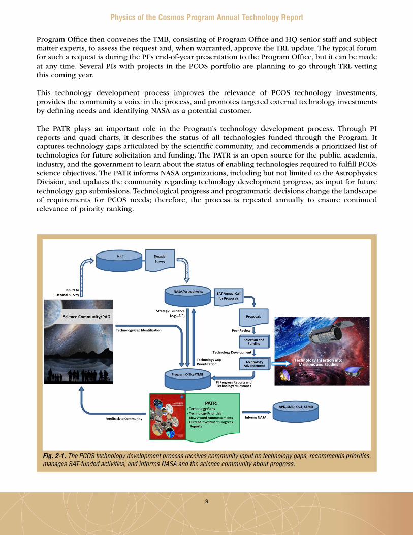
The process (Fig . 2-1), unchanged from prior years, firmly integrates the science community’s inputs through the decadal survey process and their ongoing identification of technology gaps, submitted via the PCOS Program Analysis Group (PhysPAG) or directly through the PCOS Program website . The Program Office charges its TMB to determine which technology developments will meet Program objectives, and prioritize annually the technology gaps submitted over the prior 12 months for further development consideration . The TMB ranks technology gaps based on Program objectives, strategic ranking of relevant science/missions, benefits and impacts, and timeliness . The TMB, a Program-level functional group, provides a formal mechanism for input to, and review of, PCOS technology development activities . The NASA Astrophysics Roadmap, “Enduring Quests, Daring Visions,” released in December 2013, also informs TMB deliberations . The Roadmap does not offer a vetted strategic plan, but strives to inspire and challenge the community to pursue the missions and technologies needed over the coming three decades to address NWNH-identified science goals .
Program Office priority recommendations inform Astrophysics Division decisions on which technologies to solicit in the upcoming annual SAT call for proposals, and guide selections . HQ’s investment considerations are made within a broader context, and other factors apparent at the time of selection may affect funding decisions . HQ evaluates resulting technology development proposals, considering overall scientific/technical merit, programmatic relevance, and cost reasonableness given the scope of work . Awardees work to mature their technologies from their initial TRL, normally 3, to higher TRLs, up to 5 or 6 . PIs report their progress and plans to the Program Office periodically, and submit their technologies to TRL advancement reviews when appropriate . Progress in these projects allows injection of newly mature technologies into NASA missions and studies, enabling and enhancing their capabilities with acceptable programmatic costs and risks .
TRL above the approved entry level for each technology is not official until the TMB has vetted and concurred with the development team’s assessment . When a PI believes their team has demonstrated the required progress, he or she may request a review to present their case for TRL update . The
9
Physics of the Cosmos Program Annual Technology Report
Program Office then convenes the TMB, consisting of Program Office and HQ senior staff and subject matter experts, to assess the request and, when warranted, approve the TRL update . The typical forum for such a request is during the PI’s end-of-year presentation to the Program Office, but it can be made at any time . Several PIs with projects in the PCOS portfolio are planning to go through TRL vetting this coming year .
This technology development process improves the relevance of PCOS technology investments, provides the community a voice in the process, and promotes targeted external technology investments by defining needs and identifying NASA as a potential customer .
The PATR plays an important role in the Program’s technology development process . Through PI reports and quad charts, it describes the status of all technologies funded through the Program . It captures technology gaps articulated by the scientific community, and recommends a prioritized list of technologies for future solicitation and funding . The PATR is an open source for the public, academia, industry, and the government to learn about the status of enabling technologies required to fulfill PCOS science objectives . The PATR informs NASA organizations, including but not limited to the Astrophysics Division, and updates the community regarding technology development progress, as input for future technology gap submissions . Technological progress and programmatic decisions change the landscape of requirements for PCOS needs; therefore, the process is repeated annually to ensure continued relevance of priority ranking .
Fig. 2-1. The PCOS technology development process receives community input on technology gaps, recommends priorities, manages SAT-funded activities, and informs NASA and the science community about progress.
10
Physics of the Cosmos Program Annual Technology Report
Involvement of the scientific community does not start and end with the decadal survey and technology gap submission . This community is a key stakeholder in Program technology development activities, providing feedback and inputs to the technology development process, participating in PhysPAG committees and workshops, Program workshops, ad-hoc studies, and as developers through responses to solicitations .
The PCOS Technology Development Portfolio as of 2014For FY 2014, the driving objective is to maintain progress in key enabling technologies for a future US-led X-ray mission and/or a possible future contribution to ESA L-class missions such as ATHENA, via the SAT call for proposals .
There have been 18 PCOS SAT projects awarded to date . Eleven were awarded prior to calendar year 2014 . When additional funding became available in early 2014, two more were awarded (W . Klipstein, JPL; and J . Camp, GSFC) . Table 2-1 provides top-level information on the 13 already-funded projects, including where in Appendices A and B each is described more fully . Appendix A provides single-page “quad chart” summaries for the projects . Appendix B provides PI reports, detailing development status, progress over the past year, and planned development activities for the near future . Abstracts for the five recently awarded projects, slated to begin in FY 2015, are included at the end of Appendix B . The appendices provide technology overviews and status, not flight implementation details . Additional information can be obtained by contacting the PCOS Program Office or the PIs directly . Contact information for each PI appears at the end of his or her report in Appendix B .
The Program Office manages one SAT project and one APRA project co-funded with the Game-Changing Development Program of NASA’s Space Technology Mission Directorate (STMD) . Both investigations appear in Table 2-1 . When possible, the programs leverage their limited funding to advance technologies that meet the goals of both . These two developments fit that requirement, simultaneously ranking highly among all proposals submitted to each . These collaborative investments are “win-win-win” opportunities for the Astrophysics Division, STMD, and the PI . The PCOS Program looks forward to continued relationship with STMD, creating more such opportunities in the future . Other examples of cooperation between the Astrophysics Division and STMD include collaboration on a special STMD solicitation, funding two “thin-film physics or optical coatings” investigations under the Early-Stage Innovation (ESI) solicitation . These studies, targeted for cosmic microwave background (CMB) applications, started in late 2013 and were titled “Bioinspired Broadband Antireflection Coatings at Long Wavelengths for Space Applications” (Peng Jiang, University of Florida), and “Broad Bandwidth Metamaterial Antireflection Coatings for Measurement of the Cosmic Microwave Background” (Jeff McMahon, University of Michigan) . Both projects seek to develop anti-reflection (AR) coatings that reach absorption levels near 90% for frequency bands relevant to CMB studies [3] .
11
Physics of the Cosmos Program Annual Technology Report
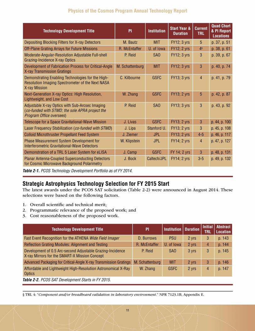
Strategic Astrophysics Technology Selection for FY 2015 StartThe latest awards under the PCOS SAT solicitation (Table 2-2) were announced in August 2014 . These selections were based on the following factors .
1 . Overall scientific and technical merit;2 . Programmatic relevance of the proposed work; and3 . Cost reasonableness of the proposed work .
Technology Development Title PI Institution Start Year & Duration
Current TRL
Quad Chart & PI Report Locations
Depositing Blocking Filters for X-ray Detectors M. Bautz MIT FY12; 3 yrs 5 p. 37, p. 51Off-Plane Grating Arrays for Future Missions R. McEntaffer U. of Iowa FY12; 2 yrs 4§ p. 38, p. 61Moderate-Angular-Resolution Adjustable Full-shell Grazing-Incidence X-ray Optics
P. Reid SAO FY12; 3 yrs 3 p. 39, p. 67
Development of Fabrication Process for Critical-Angle X-ray Transmission Gratings
M. Schattenburg MIT FY12; 3 yrs 3 p. 40, p. 74
Demonstrating Enabling Technologies for the High-Resolution Imaging Spectrometer of the Next NASA X-ray Mission
C. Kilbourne GSFC FY13; 3 yrs 4 p. 41, p. 79
Next-Generation X-ray Optics: High Resolution, Lightweight, and Low Cost
W. Zhang GSFC FY13; 2 yrs 5 p. 42, p. 87
Adjustable X-ray Optics with Sub-Arcsec Imaging (co-funded with STMD; the sole APRA project the Program Office oversees)
P. Reid SAO FY13; 3 yrs 3 p. 43, p. 92
Telescope for a Space Gravitational-Wave Mission J. Livas GSFC FY13; 2 yrs 3 p. 44, p. 100Laser Frequency Stabilization (co-funded with STMD) J. Lipa Stanford U. FY13; 2 yrs 3 p. 45, p. 108Colloid Microthruster Propellant Feed System J. Ziemer JPL FY13; 2 yrs 4-5 p. 46, p. 117Phase Measurement System Development for Interferometric Gravitational-Wave Detectors
W. Klipstein JPL FY14; 2 yrs 4 p. 47, p. 127
Demonstration of a TRL 5 Laser System for eLISA J. Camp GSFC FY 14; 2 yrs 3 p. 48, p. 131Planar Antenna-Coupled Superconducting Detectors for Cosmic Microwave Background Polarimetry
J. Bock Caltech/JPL FY14; 2 yrs 3-5 p. 49, p. 132
Table 2-1. PCOS Technology Development Portfolio as of FY 2014.
Technology Development Title PI Institution Duration Initial TRL
Abstract Location
Fast Event Recognition for the ATHENA Wide Field Imager D. Burrows PSU 2 yrs 3 p. 143Reflection Grating Modules: Alignment and Testing R. McEntaffer U. of Iowa 2 yrs 4 p. 144Development of 0.5 Arc-second Adjustable Grazing-Incidence X-ray Mirrors for the SMART-X Mission Concept
P. Reid SAO 3 yrs 3 p. 145
Advanced Packaging for Critical-Angle X-ray Transmission Gratings M. Schattenburg MIT 2 yrs 3 p. 146Affordable and Lightweight High-Resolution Astronomical X-Ray Optics
W. Zhang GSFC 2 yrs 4 p. 147
Table 2-2. PCOS SAT Development Starts in FY 2015.
§ TRL 4: “Component and/or breadboard validation in laboratory environment.” NPR 7123 .1B, Appendix E .

12
Physics of the Cosmos Program Annual Technology Report
Since these projects have only recently been selected for funding, their status is not presented yet . First-year progress for each will appear in the 2015 PCOS PATR .
The PCOS Program funds SAT proposals to advance key technologies to the point at which they may be feasibly implemented in space-flight missions . The Program focuses on those technologies most critical for substantive near-term progress on AIP and NWNH priorities . Given ESA’s selection of ATHENA, an X-ray mission, for their next L2 slot, only X-ray astrophysics was called out in the 2013 PCOS SAT solicitation as being of particular interest for the Program for possible NASA contributions . As a result, the PCOS SAT proposals selected for FY 2015 start advance five technologies important for X-ray astrophysics . Two efforts advance lightweight replicated optics, two advance high-resolution gratings, and one deals with a key technology required to read out and process data from an array of Depleted P-channel Field-Effect Transistor (DEPFET) detectors – a very-high-speed hardware/firmware event recognition processor . Four of these are returning PIs in the program . This shows that compelling proposals for follow-on development activities falling within the SAT purview are likely to successfully recompete .
Benefits Enabled by PCOS SATsAs presented at the 2014 SPIE conference in Montreal [4], the Technology Development for PCOS (TPCOS) section of the SAT program (Table 2-3) received 21 proposals in FY 2010, its first year; 26 in 2011; 10 in 2012; and eight in 2013 . The 2013 solicitation was restricted to X-ray astrophysics-related technologies, partially explaining the smaller number of proposals . Of the first set, five proposals were selected, with five more the following year, then three, and as reported here, five selected in the latest round . The historical selection rate for proposed SAT investigations for all four cycles thus stands at 28%, with the latest round hitting 63%, very high for technology development solicitations . It appears the community has gradually learned what TPCOS evaluators are seeking in PCOS SAT proposals, leading to smaller numbers of better-targeted proposals, resulting in increasing success ratios .
Perez et al. [4] reported that although the TPCOS-funded projects have provided significant positive outcomes . One specific example is the SAT-supported development of an antenna-coupled transition-edge superconducting bolometer . This technology was later deployed in the Background Imaging of Cosmic Extragalactic Polarization 2 (BICEP2) experiment in Antarctica . This detector technology allowed BICEP2 to measure B-mode polarization in the CMB signal, which may be a signature of the hypothesized inflationary
period that immediately followed the Big Bang . The technology developed through this SAT-funded project provided an order of magnitude increase in measurement speed compared to the BICEP1 experiment, allowing much clearer signal/background separation .
Another positive outcome is that the REgolith X-ray Imaging Spectrometer (REXIS), an MIT student instrument on the Origins-Spectral Interpretation-Resource Identification-Security-Regolith Explorer (OSIRIS-Rex) mission (2016 planned launch), is incorporating on its CCDs directly deposited optical blocking filters developed by another SAT project . As a bonus, the SAT project gets an opportunity to have its technique space-qualified .
Over the past year, the Program presented posters of all then-current PCOS and COR technology development projects at the American Astronomical Society (AAS) meeting in Maryland (January 2014),
Solicitation Year
TPCOS Proposals Proposal Success RatioSubmitted Selected
2010 21 5 24%2011 26 5 19%2012 10 3 30%2013 8 5 63%
Total to Date 65 18 28%
Table 2-3. Number of TPCOS SAT Proposals and Awards.

13
Physics of the Cosmos Program Annual Technology Report
Over and above the obvious benefit of supporting technology maturation, selection for SAT funding offers additional benefits to PIs, research groups, institutions, and the community . During the preparation of this PATR, the Program Office surveyed current PIs as to additional benefits resulting from their SAT funding . The following is based on responses from seven of the 12 groups currently funded . The Program Office intends to formalize the survey and expand this section in the 2015 PATR .
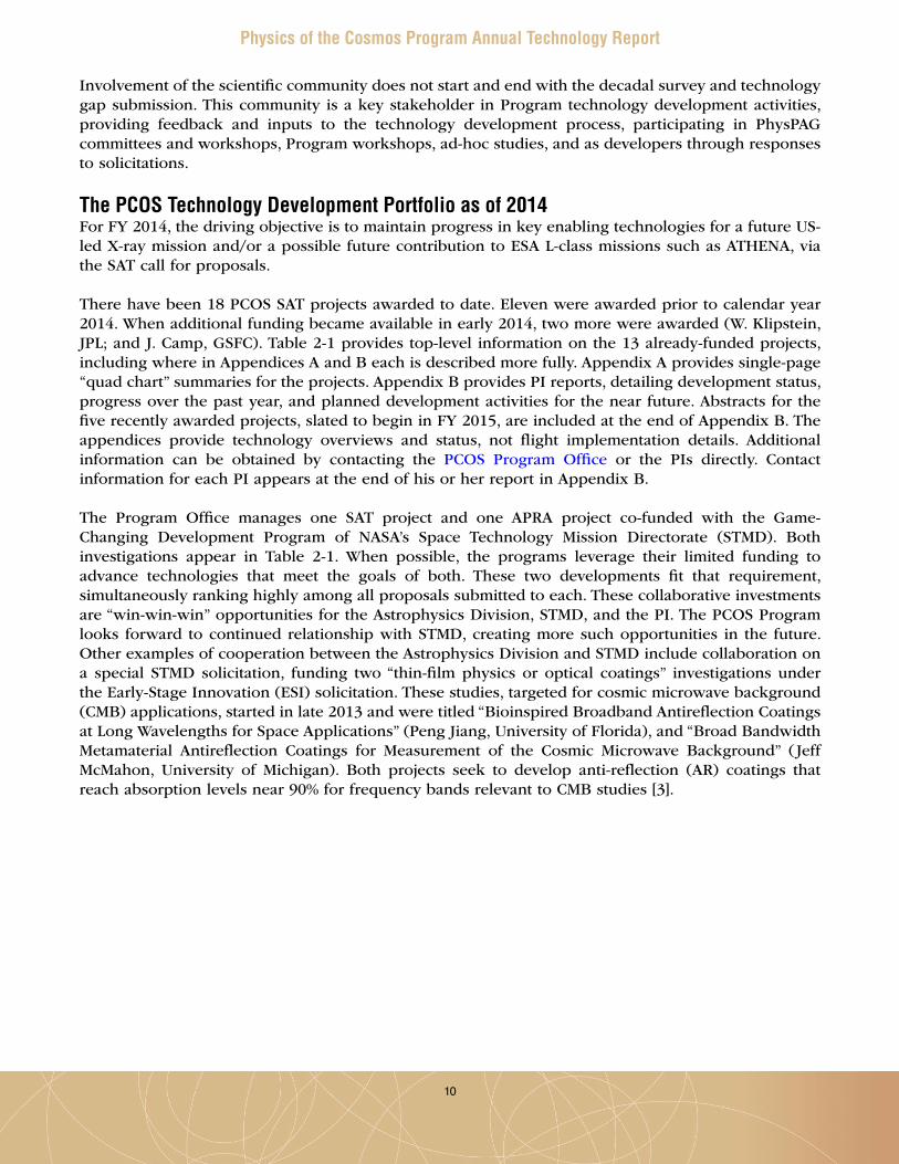
the SPIE meeting in Montreal (June 2014), and the High Energy Astrophysics Division meeting in Chicago (August 2014) . In the first of these, the Program held a successful SAT poster session with about 20 poster participants . A Special Oral Session about the SAT program was held during an evening session, and was very well received . Figure 2-2 shows a collage from that poster session, and Fig . 2-3 shows the SPIE poster .
The main benefit of the SAT program is in maturing technologies across the mid-TRL gap, so they can be injected into strategic PCOS missions and/or enable international collaboration on projects relevant to Program goals . For example, several SAT projects have advanced X-ray optics, detector, and readout technologies, providing a range of possible options for meaningful US contributions to ATHENA . Where appropriate, newly matured technologies are also likely to be implemented in ground-based and suborbital experiments, as well as Explorers and Probe-class missions . These may well extend beyond the PCOS Program, to COR, ExEP, and even outside the Astrophysics Division .
Fig. 2-2. The Program held a well-received SAT poster session at the 2014 American Astronomical Society meeting in Maryland.

14
Physics of the Cosmos Program Annual Technology Report
Most responding PIs reported they were able to leverage SAT funding to generate matching internal research and development funding, fellowships (e.g., Roman Fellowship), contributed labor and/or infrastructure funding, industry contracts, and Small Business Innovation Research (SBIR) grants . Most PIs hired students and post-doctoral fellows to assist their technology development work (on average, three or four per project), helping train the next generation of researchers and technologists needed to support future missions . At least two of those students recently converted to full-time employment status within their respective organization, indicating the Program is helping train and shape the future astrophysics work force . Some PIs went on to successfully propose additional technology development projects, through both the SAT and APRA programs .
Fig. 2-3. Poster presented at the 2014 SPIE meeting in Montreal. The Program promotes exposure of current technology development projects, highlighting their progress at national and international meetings.

15
Physics of the Cosmos Program Annual Technology Report
3. Program Technology GapsAnyone may identify a PCOS-related technology gap and submit it to the Program Office directly through the PCOS website, or via the PhysPAG . Technology gaps may be submitted throughout the year . However, to allow timely consideration by its TMB, the Program Office sets a deadline for inclusion in the current year’s ranking . In 2014, the deadline was set for June 30 . For reasons described below, this deadline will likely be moved to June 1 starting 2015 .
To maximize the likelihood of high priority ranking, the Program Office encourages submitters to include as much of the information requested as possible . More importantly, the Program Office asks submitters to describe a technology capability gap, not a specific implementation process or methodology . The technology’s goals and objectives should be clear and quantified . Additionally, a complete description of the needed capability with specific performance goals based on mission needs is very valuable . Such information serves several important purposes .
1 . The TMB is best able to assess the identified technology gap;2 . NASA HQ is best able to develop precise technology development proposal calls; and3 . The community is clearly informed and best able to match candidate technologies to mission needs .
Aside from submitter information, the technology gap form requests the following information:
• Technology gap name: Identifies the gap, and optimally the type of mission filling it would enable . • Brief description: Summarizes the technology gap and associated key performance criteria . In
general, well-defined technology gaps receive higher priority than vague ones .• Assessment of current state of the art: Describes the state of the art, allowing the TMB to
appreciate the gap between what’s available and what’s needed .• TRL: Specifies the current TRL(s) of the technology per NASA Procedural Requirements (NPR)
7123 .1B Appendix E with clear justification . The SAT program funds projects to advance technologies from TRL 3 up to TRL 5 or 6, so those already at TRL 6 are unlikely to rank well because TRLs higher than 6 are beyond the mandate of the SAT program .
• Target goals and objectives: Details the goals and/or objectives for a candidate technology to fill the described gap . For example, “The goal is to produce a detector with a sensitivity of X over a wavelength of Y to Z nm.” Technology gaps with clearly quantified objectives may receive higher priority than those without quantified objectives .
• Scientific, engineering, and/or programmatic benefits: Describes the benefits of filling the technology gap . If the need is enabling, this should describe how and why . If the need is enhancing, it should describe, and if possible quantify, the impact . Benefits could be better science, lower resource requirements (e.g., mass, power, etc .), and/or programmatic (e.g., reduced risk, cost, or schedule) . For example, “Material X is 50% stronger than the current state of the art and will enable the optical subsystem for a 2m telescope to be Y kg lighter.” Technology gaps with greater potential mission benefits receive higher scores .
• Application and potential relevant missions: Technologies enabling or enhancing missions ranked highly by the AIP, or at least by NWNH, will be scored higher . Technologies applicable to a wide range of PCOS missions, as well as COR and/or ExEP missions will rank better .
• Time to anticipated need: Specifies when the technology will need to reach TRL 6 to support anticipated mission needs . Technology gaps with shorter time windows relative to required development times receive higher priority .

16
Physics of the Cosmos Program Annual Technology Report
Technology Gaps Submitted to the 2014 TMBThe technology gaps list for 2014 included 21 entries submitted by the community to the Program Office using downloaded forms and newly provided online interactive forms . Almost all technologies developed to close these gaps would enable and/or enhance high-priority strategic missions per the AIP and/or NWNH . The PCOS TMB reviewed the 21 gaps submitted and, where appropriate, combined two or three near-duplicate technology gap entries into a single gap, or combined the wording of two entries where one covered a subset of requirements covered by another . Following this step, the TMB scored and ranked the resulting 14 unique technology gaps (Table 3-1) . These gaps cover a broad range of PCOS science, including X-ray astronomy, gravitational waves, and the inflation epoch . The technology gaps include:
• Improvements in X-ray detection and optics;• Millimeter-wave optics, detection, and polarization sensing;• Highly stable telescopes, optical benches, and lasers;• Phase measurement subsystems and gravitational reference sensors;• Gamma-ray telescopes; and• Sub-Kelvin cooling .
The Program Office will continue to solicit and compile technology gap submissions in the future . However, the Program Office would like to expand its collaboration with the PhysPAG to ensure the gaps ranked by the TMB are unique and compelling . To that end, the Program Office suggests that starting next year, the PhysPAG will take the list compiled by the Program Office and consolidate similar and/or overlapping technology gap entries . Having the PhysPAG do so prior to TMB prioritization would serve several important purposes:
• Allow experts in the relevant fields to clarify submissions and combine related and overlapping technology gaps, such that the resulting entry is more compelling, and potentially merits higher priority ranking;
• Ensure the final list accurately reflects the community-assessed gaps; and• Make the process of generating unique technology gaps more transparent to the community .
To accommodate this intermediate step, the cutoff deadline will likely move from June 30 to June 1 starting next year .

17
Physics of the Cosmos Program Annual Technology Report
Table 3-1. Technology Gaps Evaluated by TMB in 2014
Name of Technology Fast, low-noise, megapixel X-ray imaging array with moderate spectral resolution
Description Strategic X-ray missions such as SMART-X require X-ray imaging arrays covering wide fields of view with excellent spatial resolution, i.e., megapixel or higher, and moderate spectral resolution. Fast readout time is needed to minimize event pileup and dead time, and radiation hardness must be sufficient to survive likely mission duration and environment. Finally, such detectors’ power per pixel must be low enough to fit likely mission power budgets. Detector arrays meeting these requirements would also enable SMEX, Explorer, and CubeSat missions with low power budgets, in potentially harsh orbital environments.
Current State of the Art Silicon active pixel sensors (APS) currently satisfy some of the requirements, but further work is needed to meet all requirements simultaneously. APS with 36 µm pixels are at TRL 6, but noise levels are still too high, and sensitivity to soft X rays needs to improve. Sparsified readout, limited to pixels with signals, allows fast frame rates and is at TRL 3.
Current TRL 3Performance Goals and Objectives • Pixel count > 1M;
• Noise < 4e- ;• Readout speed >100 frames/s;• Rad hardness > 100 krad(Si); and• Power/pixel < 0.1 mW.
Scientific, Engineering, and/or Programmatic Benefits
Enables X-ray imaging of wide fields with high spatial resolution and sufficient spectral resolution to meet science goals of strategic X-ray missions.
PCOS Applications and Potential Relevant Missions
Examples: SMART-X, ATHENA-like, JANUS-like, XTiDE, or any other focused X-ray optics, or coded-aperture wide-field X-ray monitoring, or X-ray grating mission.
Time to Anticipated Need Earliest realistic need 2025-2030.

18
Physics of the Cosmos Program Annual Technology Report
Table 3-1. Technology Gaps Evaluated by TMB in 2014 (continued)
Name of Technology Kilo-pixel X-ray focal plane array with 2 eV spectral resolution at 6 keV
Description Covering a wide field with X-ray focal plane arrays providing acceptable spatial resolution and good spectral resolution is needed to allow study of such questions as how and why matter assembles into galactic clusters, how black holes grow, and how they influence their surroundings. This would be done through observation of X-ray emission from the neighborhood of black holes, emitted by hot matter about to be swallowed. Current X-ray focal plane arrays have insufficient pixel counts, and achieving large enough pixel counts makes energy resolution challenging.
Current State of the Art Current arrays of 32-pixels are feasible, with kilo-pixel arrays in development, but not yet demonstrated at high TRL.
Current TRL 2§§
Performance Goals and Objectives • Pixel count > 1k; and• Spectral resolution 2 eV at 6 keV.
Scientific, Engineering, and/or Programmatic Benefits
This would be an enabling technology for (a possible US contribution to) ATHENA.
PCOS Applications and Potential Relevant Missions
US contribution to ATHENA; Potential future wide-field X-ray survey missions to study the chemical evolution of the universe from z up to ~10 to the present day.
Time to Anticipated Need Assuming the ATHENA schedule is delayed enough to allow significant US contribution, this technology is needed before 2020.
§§ TRL 2: “Technology concept and/or application formulated.” NPR 7123 .1B, Appendix E .

19
Physics of the Cosmos Program Annual Technology Report
Table 3-1. Technology Gaps Evaluated by TMB in 2014 (continued)
Name of Technology High-efficiency X-ray grating arrays for high-resolution spectroscopy
Description Light-weight, high-efficiency (> 40-50%), large-format X-ray grating arrays enable spectral resolving power R > 3000 in the soft X-ray band (~ 0.2 - 2 keV) for absorption and emission line spectroscopy using large X-ray telescopes. These would provide the resolving power needed to address key science goals in the soft X-ray band, such as finding the remaining ~50% of baryonic matter in the universe, detailing matter and energy feedback from supermassive black holes, and characterizing stellar lifecycles from birth to death.
Current State of the Art Proven technologies (grating spectrometers on Chandra and XMM-Newton) fall short in efficiency, collecting area, and resolving power, by factors of 5-10. High-efficiency and high-spectral-resolving-power gratings have been demonstrated that place >40% of the incident light into the diffracted orders while also achieving spectral resolving powers >2000 in the soft X-ray band. These demonstrations place new gratings technologies at TRL 3 - 4.
Current TRL 3 – 4Performance Goals and Objectives Large-format grating arrays that place >25% of incident (0.2 - 2 keV) X-rays in the
diffraction spectrum (i.e., excluding 0th order), taking all losses into account. Dispersion must be large enough to allow R>3000.
Scientific, Engineering, and/or Programmatic Benefits
Spectrometers achieving R>3000 throughout the soft X-ray band are mission-enabling, as micro-calorimeters cannot achieve that. Soft X-ray spectroscopy was listed as a priority in the NWNH report.
PCOS Applications and Potential Relevant Missions
Grating development has been a focus area for PCOS over the last few years. Much advancement has been made in SAT, Roman Technology Fellowship (RTF), and APRA programs focused on developing these spectrometers. Grating spectrometers were baselined for missions such as the Off-plane Grating Rocket Experiment (OGRE), an upcoming Explorer proposal named Arcus, and SMART-X.
Time to Anticipated Need Grating development should be at TRL 5 around the time of the Explorer Announcement of Opportunity (AO), round after next (presumably ~2017).

20
Physics of the Cosmos Program Annual Technology Report
Table 3-1. Technology Gaps Evaluated by TMB in 2014 (continued)
Name of Technology Affordable, lightweight X-ray optics with 5 arcsec resolution
Description Future X-ray observatories need X-ray mirrors qualitatively and quantitatively better than any currently in operation. Improvements are needed in one or more of the following:
1) Angular resolution; 2) Photon collecting area per unit mass; and 3) Cost per unit photon collecting area.
Proposed technology improvement methods may include: piezo, magnetic smart material (MSM) shaping with magnetic field; ion implantation, zero stress Si, over-coating, coating the substrate back with a localized and controlled “stressy” material.
Current State of the Art State of the art of lightweight X-ray optics is represented by GSFC-developed slumped glass optics, currently at TRL 5 for 10” mirror assemblies.
Chandra optics: • Angular resolution <1 arcsec; • Effective area 400 cm2 at 5 keV; and• Mirror mass 951 kg.
Current TRL 5Performance Goals and Objectives • Size: 1” mirror assemblies for major mission; 5” for several Explorers;
• Angular resolution <5 arcsec (sub-arcsec desired);• Photon-collecting area per unit mass several orders of magnitude greater than that of
Chandra; and• Cost per photon-collecting area 50 times lower than Chandra.
Scientific, Engineering, and/or Programmatic Benefits
This type of X-ray optics will enable study of the early universe to complement JWST. It will maintain US leadership in lightweight X-ray optics for space. It will facilitate future missions and minimize their schedule and costs.
PCOS Applications and Potential Relevant Missions
Enabling technology for (possible US contribution to) ESA’s ATHENA mission. Also enabling for several Explorer missions.
Time to Anticipated Need Assuming the ATHENA schedule is delayed enough to allow significant US contribution, this technology is needed before 2020.

21
Physics of the Cosmos Program Annual Technology Report
Table 3-1. Technology Gaps Evaluated by TMB in 2014 (continued)
Name of Technology Advanced millimeter-wave focal plane arrays for CMB polarimetry
Description The Inflation Probe requires arrays of detectors with background-limited sensitivity, dual polarization detection capability, and good control of systematic errors at multiple frequencies between ~30 and ~300 GHz for foreground removal.
Architectures must be scalable to ~kilo-pixel arrays for the requisite sensitivity. Being able to separate two polarizations, simultaneous multiband operation, and high multiplexing factors are all desirable qualities. For spaceflight, these detectors should have the highest possible efficiency and need to be compatible with the space environment. This includes low dielectric exposure to low-energy electrons and robust performance in the presence of cosmic-ray impacts.
Continued deployment in ground-based and balloon-borne platforms will benefit development efforts.
Current State of the Art A great deal of progress has been made with a variety of approaches, including antenna-coupling into transmission-line micro-machined structures, waveguide probes, and absorber-coupled filled arrays.
Transition-edge sensors are currently the leading candidate technology for the detecting element in these integrated sensors. Arrays of several thousand detectors are operating in ground-based CMB polarization experiments. Balloon experiments will operate detectors in the environment closest to space.
Current TRL 4Performance Goals and Objectives The detectors must demonstrate operation over a wide frequency range (30-300 GHz),
scale to a focal plane architecture appropriate for space, provide appropriate magnetic shielding, provide cosmic-ray immunity, realize extreme noise stability, and feature high detector efficiency. Process uniformity and high yield are also important.
Scientific, Engineering, and/or Programmatic Benefits
Measurement of CMB polarization to search for evidence of, and characterize, inflation is a top NASA priority. Such detectors are a key enabling technology. A space-borne measurement can probe for a polarization pattern imprinted by a background of gravitational waves generated at the time of inflation in the early universe. Polarization measurements on finer angular scales probe large-scale structure sensitive to neutrino mass and dark energy.
PCOS Applications and Potential Relevant Missions
These are needed for measuring CMB polarization to search for and characterize the faint, polarized signature of inflation. The targeted mission is Inflation Probe as recommended in the NWNH report. Other possibilities include Explorer and international CMB polarization and absolute spectrum experiments. Development also has technological overlaps with superconducting far-IR and X-ray detectors.
Time to Anticipated Need As ground-based and balloon-borne measurements continue to improve, NWNH recommended a mid-decade review accompanied by increased investment in technology to enable a space mission. Flight readiness in the late 2020s is appropriate.

22
Physics of the Cosmos Program Annual Technology Report
Table 3-1. Technology Gaps Evaluated by TMB in 2014 (continued)
Name of Technology Millimeter-wave filters and coatings
Description High-throughput telescope and optical elements with controlled polarization properties are required for the Inflation Probe. These require development of mm-wave filters and coatings.
Current State of the Art Single-layer anti-reflection coatings in widespread use in various dielectrics.Current TRL 2 – 5Performance Goals and Objectives Develop robust multi-layer coatings for broad-band applications. Develop thermal filtering
technologies suitable for large focal plane arrays operating at sub-Kelvin temperatures.Scientific, Engineering, and/or Programmatic Benefits
Broad-band optics can reduce the necessary focal plane mass and volume for CMB polarization measurements. This may open options for compact optical systems appropriate for lower-cost Explorer opportunities; an international mission concept using broad-band refracting optics is in the planning stages.
PCOS Applications and Potential Relevant Missions
Inflation Probe, Explorer, and international experiments to study CMB polarization and absolute spectrum.
Time to Anticipated Need Needed in the late 2020s.

23
Physics of the Cosmos Program Annual Technology Report
Table 3-1. Technology Gaps Evaluated by TMB in 2014 (continued)
Name of Technology Quasi-optical millimeter-wave polarization modulators
Description Measurement of CMB polarization on large scales likely requires rapid polarization modulation to separate sky-signal polarized intensity from instrumental effects. Employing modulators large enough to span the telescope primary aperture is an advantage in that sky polarization can be modulated before the signal is contaminated by the instrument.
Current State of the Art Several experiments in the field are currently using rapidly spinning half-wave plates as the primary means of modulating the signal and separating it from longer time variations. More experiments are coming online using both half-wave plates and variable-delay polarization modulators that endeavor to measure larger areas of the sky.
Current TRL 4Performance Goals and Objectives Develop space-compatible modulators, including work on frequency-selective surfaces
and mechanisms compatible with the space environment. Minimizing dielectric cross-section to low-energy electrons is a priority.
Develop and compare strategies for instrument architectures with and without rapid modulators.
Scientific, Engineering, and/or Programmatic Benefits
Measurement of CMB polarization to search for evidence of, and characterize inflation is a top NASA priority. Modulators are potentially a key enabling technology.
PCOS Applications and Potential Relevant Missions
The targeted mission is Inflation Probe as recommended in the NWNH report.
Time to Anticipated Need Needed in the late 2020s.
24
Physics of the Cosmos Program Annual Technology Report
Table 3-1. Technology Gaps Evaluated by TMB in 2014 (continued)
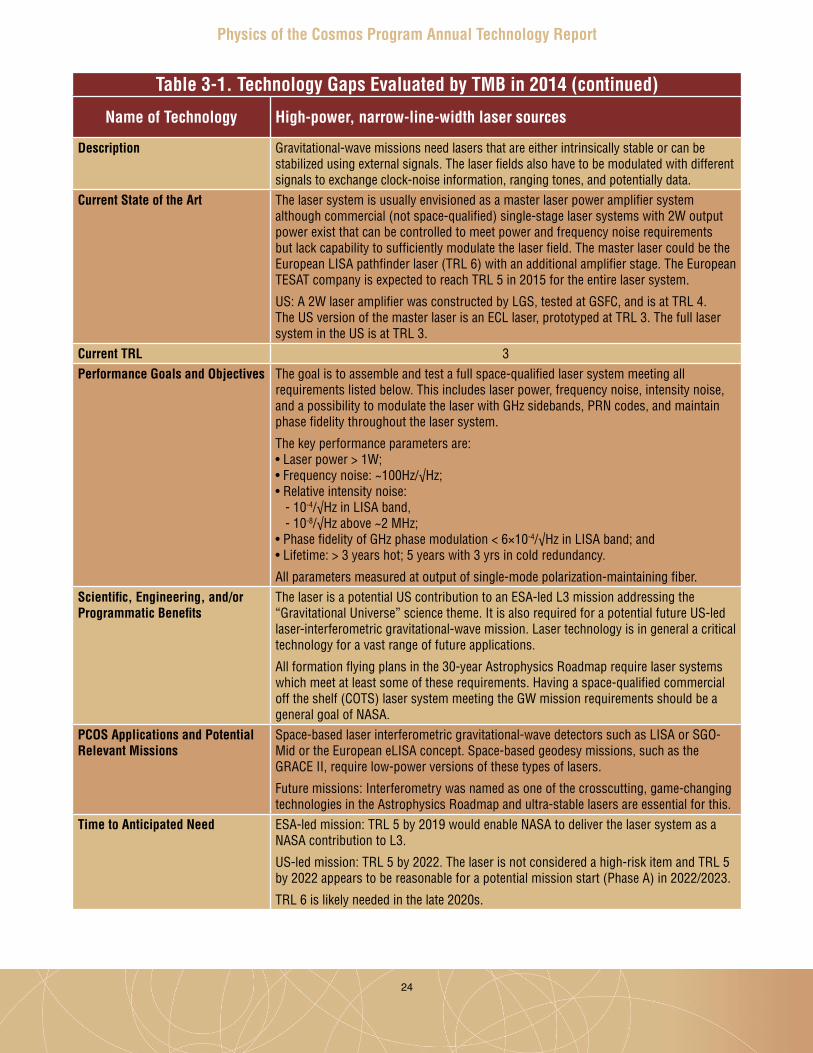
Name of Technology High-power, narrow-line-width laser sources
Description Gravitational-wave missions need lasers that are either intrinsically stable or can be stabilized using external signals. The laser fields also have to be modulated with different signals to exchange clock-noise information, ranging tones, and potentially data.
Current State of the Art The laser system is usually envisioned as a master laser power amplifier system although commercial (not space-qualified) single-stage laser systems with 2W output power exist that can be controlled to meet power and frequency noise requirements but lack capability to sufficiently modulate the laser field. The master laser could be the European LISA pathfinder laser (TRL 6) with an additional amplifier stage. The European TESAT company is expected to reach TRL 5 in 2015 for the entire laser system.
US: A 2W laser amplifier was constructed by LGS, tested at GSFC, and is at TRL 4. The US version of the master laser is an ECL laser, prototyped at TRL 3. The full laser system in the US is at TRL 3.
Current TRL 3Performance Goals and Objectives The goal is to assemble and test a full space-qualified laser system meeting all
requirements listed below. This includes laser power, frequency noise, intensity noise, and a possibility to modulate the laser with GHz sidebands, PRN codes, and maintain phase fidelity throughout the laser system.
The key performance parameters are: • Laser power > 1W;• Frequency noise: ~100Hz/√Hz; • Relative intensity noise: - 10-4/√Hz in LISA band, - 10-8/√Hz above ~2 MHz; • Phase fidelity of GHz phase modulation < 6×10⁻⁴/√Hz in LISA band; and • Lifetime: > 3 years hot; 5 years with 3 yrs in cold redundancy.
All parameters measured at output of single-mode polarization-maintaining fiber.Scientific, Engineering, and/or Programmatic Benefits
The laser is a potential US contribution to an ESA-led L3 mission addressing the “Gravitational Universe” science theme. It is also required for a potential future US-led laser-interferometric gravitational-wave mission. Laser technology is in general a critical technology for a vast range of future applications.
All formation flying plans in the 30-year Astrophysics Roadmap require laser systems which meet at least some of these requirements. Having a space-qualified commercial off the shelf (COTS) laser system meeting the GW mission requirements should be a general goal of NASA.
PCOS Applications and Potential Relevant Missions
Space-based laser interferometric gravitational-wave detectors such as LISA or SGO-Mid or the European eLISA concept. Space-based geodesy missions, such as the GRACE II, require low-power versions of these types of lasers.
Future missions: Interferometry was named as one of the crosscutting, game-changing technologies in the Astrophysics Roadmap and ultra-stable lasers are essential for this.
Time to Anticipated Need ESA-led mission: TRL 5 by 2019 would enable NASA to deliver the laser system as a NASA contribution to L3.
US-led mission: TRL 5 by 2022. The laser is not considered a high-risk item and TRL 5 by 2022 appears to be reasonable for a potential mission start (Phase A) in 2022/2023.
TRL 6 is likely needed in the late 2020s.
25
Physics of the Cosmos Program Annual Technology Report
Table 3-1. Technology Gaps Evaluated by TMB in 2014 (continued)
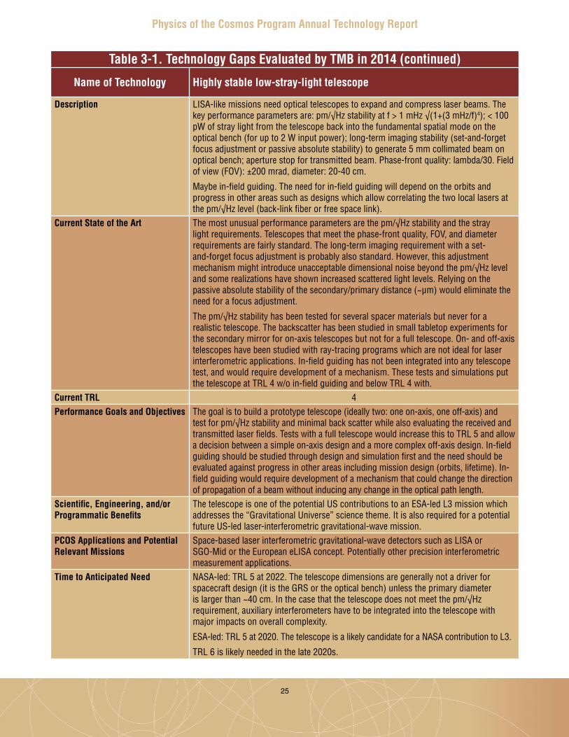
Name of Technology Highly stable low-stray-light telescope
Description LISA-like missions need optical telescopes to expand and compress laser beams. The key performance parameters are: pm/√Hz stability at f > 1 mHz √(1+(3 mHz/f)4); < 100 pW of stray light from the telescope back into the fundamental spatial mode on the optical bench (for up to 2 W input power); long-term imaging stability (set-and-forget focus adjustment or passive absolute stability) to generate 5 mm collimated beam on optical bench; aperture stop for transmitted beam. Phase-front quality: lambda/30. Field of view (FOV): ±200 mrad, diameter: 20-40 cm.
Maybe in-field guiding. The need for in-field guiding will depend on the orbits and progress in other areas such as designs which allow correlating the two local lasers at the pm/√Hz level (back-link fiber or free space link).
Current State of the Art The most unusual performance parameters are the pm/√Hz stability and the stray light requirements. Telescopes that meet the phase-front quality, FOV, and diameter requirements are fairly standard. The long-term imaging requirement with a set-and-forget focus adjustment is probably also standard. However, this adjustment mechanism might introduce unacceptable dimensional noise beyond the pm/√Hz level and some realizations have shown increased scattered light levels. Relying on the passive absolute stability of the secondary/primary distance (~µm) would eliminate the need for a focus adjustment.
The pm/√Hz stability has been tested for several spacer materials but never for a realistic telescope. The backscatter has been studied in small tabletop experiments for the secondary mirror for on-axis telescopes but not for a full telescope. On- and off-axis telescopes have been studied with ray-tracing programs which are not ideal for laser interferometric applications. In-field guiding has not been integrated into any telescope test, and would require development of a mechanism. These tests and simulations put the telescope at TRL 4 w/o in-field guiding and below TRL 4 with.
Current TRL 4Performance Goals and Objectives The goal is to build a prototype telescope (ideally two: one on-axis, one off-axis) and
test for pm/√Hz stability and minimal back scatter while also evaluating the received and transmitted laser fields. Tests with a full telescope would increase this to TRL 5 and allow a decision between a simple on-axis design and a more complex off-axis design. In-field guiding should be studied through design and simulation first and the need should be evaluated against progress in other areas including mission design (orbits, lifetime). In-field guiding would require development of a mechanism that could change the direction of propagation of a beam without inducing any change in the optical path length.
Scientific, Engineering, and/or Programmatic Benefits
The telescope is one of the potential US contributions to an ESA-led L3 mission which addresses the “Gravitational Universe” science theme. It is also required for a potential future US-led laser-interferometric gravitational-wave mission.
PCOS Applications and Potential Relevant Missions
Space-based laser interferometric gravitational-wave detectors such as LISA or SGO-Mid or the European eLISA concept. Potentially other precision interferometric measurement applications.
Time to Anticipated Need NASA-led: TRL 5 at 2022. The telescope dimensions are generally not a driver for spacecraft design (it is the GRS or the optical bench) unless the primary diameter is larger than ~40 cm. In the case that the telescope does not meet the pm/√Hz requirement, auxiliary interferometers have to be integrated into the telescope with major impacts on overall complexity.
ESA-led: TRL 5 at 2020. The telescope is a likely candidate for a NASA contribution to L3.
TRL 6 is likely needed in the late 2020s.

26
Physics of the Cosmos Program Annual Technology Report
Table 3-1. Technology Gaps Evaluated by TMB in 2014 (continued)
Name of Technology Low-mass, long-term-stability optical bench
Description Space-based laser interferometric gravitational-wave missions need optical benches to prepare, split, direct, and combine the different laser fields to form all required beat signals.
Key performance parameters are: √(1+(1mHz/f)4) pm/√Hz, long-term alignment stability, low mass, and simple assembly procedures (LISA-like missions require six flight units alone).
Current State of the Art Europe developed the optical bench for LISA Pathfinder using an all-Zerodur, hydroxide-bonded bench (TRL 6 now). It meets the stability requirement. However, the assembly of the bench took very long and was always on or near the critical path. This technology does not scale well for the 4× larger LISA bench which also carries 4× more components, and LISA requires six flight units instead of one. A different manufacturing technology based on more classical mechanical mounts has to be developed and tested to reduce this major programmatic risk. This different technology is probably at TRL 2 in the US.
Current TRL 2Performance Goals and Objectives An optical bench with classical mechanical mirror mounts and metal benches saves
mass and time compared to an all-Zerodur hydroxide-bonded bench. However, it still has to be shown that such a bench can meet the pm/√Hz requirement with components that can stay aligned during launch or can be realigned on-orbit.
Alternatively, an all-Zerodur hydroxide-bonded bench with simplified and accelerated manufacturing processes would significantly reduce the development time and difficulty.
Scientific, Engineering, and/or Programmatic Benefits
The optical bench is a critical item for all space-based, laser interferometric GW detectors. It is only available from a single foreign ‘vendor’, the University of Glasgow and this group is at risk of losing the knowledge and capability over the next few years. This programmatic risk needs to be addressed.
A lighter and easier-to-assemble optical bench would significantly reduce cost and programmatic risks associated with any complex assembly process.
In addition, the bench could be a deliverable for NASA should the US join the ESA-led mission addressing the “Gravitational Universe” science theme (L3).
PCOS Applications and Potential Relevant Missions
Space-based laser interferometric gravitational-wave detectors such as LISA or SGO-Mid or the European eLISA concept but also other interferometric future missions; interferometry has been named as one of the crosscutting, game-changing technologies in the Astrophysics Roadmap.
Time to Anticipated Need NASA-led:
TRL 4 in 2020 / TRL 5 in 2022. The optical bench is the core piece for interferometry in space-based GW missions, interfacing with many other subsystems. The definition of these interfaces depends on bench design. It is thus crucial to have a good idea what type of bench will be used.
ESA-led: TRL 5 by 2020.
TRL 6 is likely needed in the late 2020s.
27
Physics of the Cosmos Program Annual Technology Report
Table 3-1. Technology Gaps Evaluated by TMB in 2014 (continued)
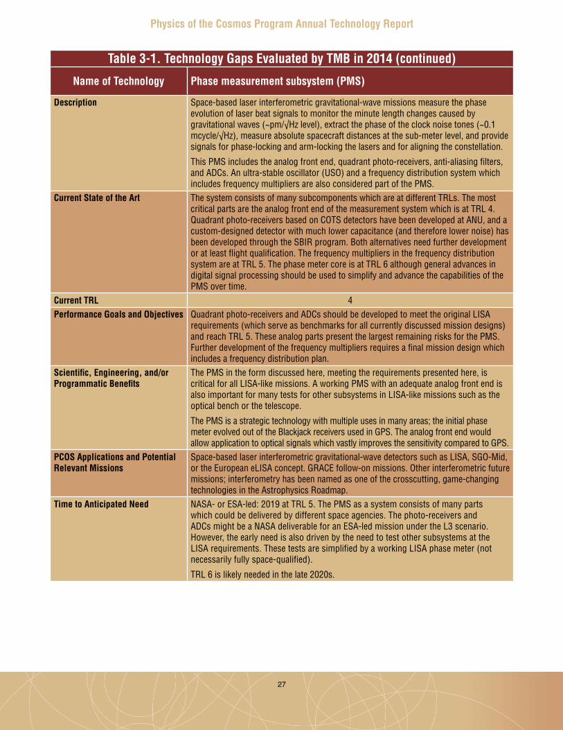
Name of Technology Phase measurement subsystem (PMS)
Description Space-based laser interferometric gravitational-wave missions measure the phase evolution of laser beat signals to monitor the minute length changes caused by gravitational waves (~pm/√Hz level), extract the phase of the clock noise tones (~0.1 mcycle/√Hz), measure absolute spacecraft distances at the sub-meter level, and provide signals for phase-locking and arm-locking the lasers and for aligning the constellation.
This PMS includes the analog front end, quadrant photo-receivers, anti-aliasing filters, and ADCs. An ultra-stable oscillator (USO) and a frequency distribution system which includes frequency multipliers are also considered part of the PMS.
Current State of the Art The system consists of many subcomponents which are at different TRLs. The most critical parts are the analog front end of the measurement system which is at TRL 4. Quadrant photo-receivers based on COTS detectors have been developed at ANU, and a custom-designed detector with much lower capacitance (and therefore lower noise) has been developed through the SBIR program. Both alternatives need further development or at least flight qualification. The frequency multipliers in the frequency distribution system are at TRL 5. The phase meter core is at TRL 6 although general advances in digital signal processing should be used to simplify and advance the capabilities of the PMS over time.
Current TRL 4Performance Goals and Objectives Quadrant photo-receivers and ADCs should be developed to meet the original LISA
requirements (which serve as benchmarks for all currently discussed mission designs) and reach TRL 5. These analog parts present the largest remaining risks for the PMS. Further development of the frequency multipliers requires a final mission design which includes a frequency distribution plan.
Scientific, Engineering, and/or Programmatic Benefits
The PMS in the form discussed here, meeting the requirements presented here, is critical for all LISA-like missions. A working PMS with an adequate analog front end is also important for many tests for other subsystems in LISA-like missions such as the optical bench or the telescope.
The PMS is a strategic technology with multiple uses in many areas; the initial phase meter evolved out of the Blackjack receivers used in GPS. The analog front end would allow application to optical signals which vastly improves the sensitivity compared to GPS.
PCOS Applications and Potential Relevant Missions
Space-based laser interferometric gravitational-wave detectors such as LISA, SGO-Mid, or the European eLISA concept. GRACE follow-on missions. Other interferometric future missions; interferometry has been named as one of the crosscutting, game-changing technologies in the Astrophysics Roadmap.
Time to Anticipated Need NASA- or ESA-led: 2019 at TRL 5. The PMS as a system consists of many parts which could be delivered by different space agencies. The photo-receivers and ADCs might be a NASA deliverable for an ESA-led mission under the L3 scenario. However, the early need is also driven by the need to test other subsystems at the LISA requirements. These tests are simplified by a working LISA phase meter (not necessarily fully space-qualified).
TRL 6 is likely needed in the late 2020s.

28
Physics of the Cosmos Program Annual Technology Report
Table 3-1. Technology Gaps Evaluated by TMB in 2014 (continued)
Name of Technology Gravitational reference sensor (GRS)
Description The ideal GRS is a free-falling test mass which is only subject to the tidal forces caused by gravitational waves. The GRS envisioned for LISA-like missions is a 2kg gold/platinum cube surrounded by electrodes used to sense the position of the test mass with respect to the spacecraft and also apply forces in all non-sensitive directions to the test mass. This GRS as a technical unit also includes the electrode housing, caging mechanisms, UV-discharging, vacuum systems, and front-end electronics.
Current State of the Art ESA will test a GRS (and the also-required disturbance reduction system, DRS) in the LISA Pathfinder mission. NASA will contribute a second DRS (ST7 component of the LPF). Preflight, the European GRS is at TRL 6. NASA has nothing comparable and it is difficult to assign a reasonable TRL for this specific case.
Current TRL See above statementPerformance Goals and Objectives The long-term goal is to develop competency in the US in GRS technology. The
immediate goals are to design and fabricate a TRL-3 electrode housing, construct a torsion-pendulum test facility to evaluate the performance of the GRS housing, and develop a charge-management system based on UV-LEDs (rather than the mercury discharge lamps used by LPF).
Scientific, Engineering, and/or Programmatic Benefits
GRS technology is absolutely critical for any gravitational-wave detector mission. Having no competencies in the US puts us in an impossible position for a NASA-led mission which would address one of the leading science goals of the last two decadal surveys.
PCOS Applications and Potential Relevant Missions
LISA-like space-based gravitational-wave missions and, with relaxed requirements, geodesy missions.
Time to Anticipated Need NASA-led: TRL 3 by 2018 latest. TRL 5 by 2022.
ESA-led: TRL 3 by 2018 to develop competency and the possibility of alternative vendors should the single vendor in Italy not be able to deliver anymore.
TRL 6 is likely needed in the late 2020s.

29
Physics of the Cosmos Program Annual Technology Report
Table 3-1. Technology Gaps Evaluated by TMB in 2014 (continued)
Name of Technology High-performance gamma-ray telescope
Description Two technologies are needed to enable gaseous detectors, e.g., Time Projection Chambers (TPC), with large volumes, 10s to 100s of m3, to be inflated on orbit:
1) The inflatable pressure shell must contain the detector gas at pressures up to ~3 atm, be capable of self-sealing against micro-meteors, and have a surface density of <1 g/cm2. The TPC field-shaping electrodes are mounted on the inner surface of the inflatable shell and deploy as the shell inflates to positions accurate to ~1 mm.
2) The TPC readout structure at the bottom of the TPC must unfold within the gas volume, be rigid, and have position accuracy of ~1 mm.
Current State of the Art Thin Red Line Aerospace developed and supplied 20 full-fidelity inflatable pressure shells of up to 320 m3 volume for Bigelow Aerospace inflatable habitat Genesis spacecraft flight hardware. Thin Red Line designed, engineered, and manufactured the pressure-restraining hulls of Genesis 1 and 2 (launched 7/2006 and 6/2007, respectively), the first spacecraft on orbit successfully incorporating large-volume, high-stress inflatable architecture. See http://www.thin-red-line.com/projects.html for other projects. Large deployable mirrors have been developed for JWST. This technology could be adapted for the deployable TPC readout.
Current TRL 6Performance Goals and Objectives The goal is to enable construction of a ~100 m3 gamma-ray pair telescope with arc-
minute angular resolution and continuum sensitivity of better than 5×10⁻⁷ between ~100 MeV and ~10 GeV.
The objectives can be met by demonstrating an inflatable TPC gas shell with volume
~10 m3 at ~1 atm and deployable readout electrodes with area of ~2 m2.Scientific, Engineering, and/or Programmatic Benefits
Inflatable gaseous detectors would enable gamma-ray telescopes to achieve arc-minute angular resolution. Deployable 2D readout structures within a large gas volume would increase telescope sensitivity.
PCOS Applications and Potential Relevant Missions
Arc-minute gamma-ray telescope.
Time to Anticipated Need Demonstration at TRL 3-4 by release of FY16-17 Explorer AO. TRL 6+ a few years later, before launch of Explorer.

30
Physics of the Cosmos Program Annual Technology Report
Table 3-1. Technology Gaps Evaluated by TMB in 2014 (continued)
Name of Technology Sub-Kelvin cooling system including a high-efficiency cryo-cooler and/or an ADR stage
Description Stable and continuous sub-Kelvin cooling systems with high thermal lift capacity are needed for the Inflation Probe and benefit planned X-ray and far-IR missions.
The demonstrated open-cycle dilution refrigerator on Planck does not scale to higher power loading. Approaches based on adiabatic demagnetization refrigeration (ADR), 3He sorption cooling, or closed-cycle dilution offer avenues to provide improved performance.
Current State of the Art The Planck satellite demonstrated continuous cooling to 100 mK for 2.5 years.Current TRL 6Performance Goals and Objectives Continuous and stable cooling to 100 mK without cryogens.
The cooling power must be increased beyond that provided by the Planck system for large focal planes, and the implementation simplified for lower cost mission opportunities.
Scientific, Engineering, and/or Programmatic Benefits
Enables next-generation measurements of CMB polarization.
Eliminates cryogens which limit mission life.
Simplified approach lowers cost.PCOS Applications and Potential Relevant Missions
Inflation Probe, Explorer, and international CMB polarization and absolute spectrum experiments, X-ray applications with cryogenic detectors, and far-IR instrumentation.
Time to Anticipated Need A high-capacity, continuous-cooling system should be at TRL 6 for the 2020 Decadal Survey.
31
Physics of the Cosmos Program Annual Technology Report
4. Program Technology Priorities and Recommendations
BackgroundAs part of its annual technology prioritization process, the Program Office convened a TMB to prioritize the technology gaps submitted . The TMB followed an agreed-upon set of evaluation criteria, resulting in the priorities shown below . TMB membership included senior staff from NASA HQ Astrophysics Division, the Program Office, STMD, and the Aerospace Corporation . For 2014, the TMB used a prioritization approach similar to that used in prior years, with a streamlined set of four criteria . These included strategic alignment, benefits and impacts, applicability, and timeliness .
• Strategic alignment: How well does the technology gap align with the science and/or programmatic priorities of the AIP or current programmatic assessment?
• Benefits and impacts: How much impact would filling the technology gap have on notional PCOS mission(s)? To what degree would such technology enable and/or enhance achievable science objectives, reduce cost, and/or reduce mission risks?
• Scope of applicability: How crosscutting is the technology? How many Astrophysics programs and/or mission concepts could benefit from this technology?
• Time to anticipated need: When does the technology need to be at TRL 6? The Astrophysics Division requires that critical/enabling technology used by projects be at TRL 6 at Key Decision Point (KDP) B, and non-critical/enhancing technology be at TRL 6 at KDP C** . Note that these requirements are more stringent than general NASA guidelines .
The TMB assigned weighting factors, reflecting the relative importance placed on each criterion . Each technology gap received a score of 0 to 4 for each criterion . The scores were multiplied by their respective weights, and the products were summed . Some technologies could be scored based on several missions or mission classes . In such cases, the TMB scored each scenario independently; assigning the highest overall score (e.g., a gap might receive an overall score of 91 for a highly aligned mission, but only 75 for a less-aligned class of missions, in which case it was assigned the higher score) . Table 4-1 details the criteria descriptions, weighting factors, and TMB scoring guidelines .
This process provides a rigorous, transparent ranking of technology gaps based on the Program’s goals, community scientific rankings of relevant missions, Astrophysics Division priorities as outlined in the AIP, and the external programmatic environment . Since the SAT program is intended to promote development and maturation of technologies relevant to missions and concepts identified as strategic, the strategic alignment criterion is driven by the AIP, which is in turn based on NWNH . The AIP details highly ranked science missions and technology development, which for PCOS include dark energy, gravitational waves, X-ray astronomy, and cosmic inflation; and prioritizes those based on current budget realities .
** See NASA Procedural Requirement 7120 .5E to learn more about project KDPs .

32
Physics of the Cosmos Program Annual Technology Report
CriterionW
eigh
t
Max
Sco
re
Max
Wei
ghte
d Sc
ore
General Description/
Question4 3 2 1 0
Strategic Alignment
10 4 40 How well does the technology align with PCOS science and/or programmatic priorities of AIP or current programmatic assessment?
Applicable mission concept receives highest AIP consideration
Applicable mission concept receives medium AIP consideration
Applicable mission concept receives low AIP consideration
Applicable mission concept not considered in AIP but was positively addressed in NWNH
Not considered by the AIP or NWNH
Benefits and Impacts
9 4 36 How much impact does the technology have on notional mission(s)? To what degree does it enable and/or enhance achievable science objectives, reduce cost, and/or reduce mission risks?
Critical and key enabling technology - required to meet mission concept objective(s); without this technology mission(s) will not be launched
Highly desirable technology - not mission-critical, but provides major benefits in enhanced science capability, reduced critical resources need, and/or reduced mission risks; without this technology mission(s) may be launched, but likely results would be severely degraded
Desirable - offers significant science or implementation benefits but not required for mission success; if technology is available, would almost certainly be implemented in mission(s)
Minor science impact or implementation improvements; if technology is available, would be considered for implementation in mission(s)
No science impact or implementation improvement; even if available, technology would not be implemented in mission(s)
Scope of Applicability
3 4 12 How crosscutting is the technology? How many Astrophysics programs and/or mission concepts could benefit from this technology?
Applies widely to PCOS mission concepts and both COR and ExEP mission concepts
Applies widely to PCOS mission concepts and either COR or ExEP mission concepts
Applies widely to PCOS mission concepts
Applies to a single PCOS mission concept
No known applicable PCOS mission concept
Time To Anticipated Need
3 4 12 When does technology need to be at TRL 6? (Critical/enabling technology must be at TRL 6 by KDP B; Non-critical/enhancing technology by KDP C)
TRL 6 needed within 5 years (before 2020)
TRL 6 needed within 6 to 10 years (2020 - 2024)
TRL 6 needed within 11 to 15 years (2025 - 2029)
TRL 6 needed within 16 to 20 years (2030 - 2034)
TRL 6 needed in more than 20 years (2035 or later)
Table 4-1. Clear, strategic criteria provide a rigorous, transparent process for prioritizing technology gaps.
33
Physics of the Cosmos Program Annual Technology Report
ResultsAs mentioned above, in 2014, the PCOS TMB received 21 technology gaps . As a first step, the TMB considered which entries were close enough to each other that combining them and scoring them together would strengthen their case . Following that step, the TMB scored a final set of 14 gaps . After reviewing the scores, the TMB binned the technology gaps into three groups based on a number of factors, including primarily a natural grouping of overall scores . The groups were as follows (with all entries within a group ranked equally):
Priority 1: Technologies the TMB determined to be of the highest interest to the PCOS Program . Filling these gaps would provide key enabling technologies for the highest-priority strategic PCOS missions including potential US contribution to ESA’s ATHENA X-ray mission, gravitational-wave missions, and a potential Inflation Probe mission . The TMB recommends SAT calls and award decisions address these technology gaps first .
1 . Kilo-pixel X-ray focal plane array with 2 eV energy resolution at 6 keV;2 . Affordable, lightweight, 5 arcsec resolution X-ray optics;3 . High-power, narrow-line-width laser sources;4 . Highly stable, low-stray-light telescope;5 . Phase-measurement subsystem; and6 . Sub-Kelvin cooling systems .
Priority 2: Technologies the TMB believes would be critical, highly desirable, or desirable for X-ray missions beyond ATHENA or potential gravitational-wave and Inflation Probe missions . The TMB recommends that should sufficient funding be available, SAT calls and award decisions address closing these technology gaps as well .
1 . High-efficiency X-ray gratings for high-resolution spectroscopy;2 . Advanced millimeter-wave focal plane arrays for CMB polarimetry;3 . Fast, low-noise megapixel X-ray imaging array with moderate spectral resolution;4 . Quasi-optical millimeter-wave polarization modulators;5 . Low-mass, long-term stability optical bench; and6 . Millimeter-wave coatings and filters .
Priority 3: Technologies the TMB deemed supportive of PCOS objectives, but scoring lower than Priority 1 and 2 technology gaps .
1 . Gravitational reference sensor; and2 . High-performance gamma-ray telescope .

34
Physics of the Cosmos Program Annual Technology Report
5. Closing RemarksThis 2014 PCOS PATR serves as the current snapshot of the dynamic state of technology development managed by the Program Office and provides future directions for technology planning and maturation . As we complete another year of PCOS technology development activities, we see many positive developments .
Our technology development portfolio is growing, and continues to deliver excellent progress . All funded technologies are maturing toward higher TRLs . PCOS SAT investments are generating benefits beyond the direct advancement of strategic technologies . These include PIs leveraging funding from internal and external (including non-NASA) sources; hiring students and post-docs, thereby training our future astrophysics workforce; and generating research collaborations and industry partnerships, in support of PCOS science goals .
Our established and streamlined technology gap prioritization process continues to adhere to AIP and NWNH strategic guidance, with the TMB assigning the most significant weight in technology gap prioritization to strategic alignment . As a result, the Astrophysics Division continues to fund projects addressing technology gaps identified by the TMB as having the highest priority . For FY 2015 start, this includes five technologies supporting future X-ray missions in the areas of lightweight replicated optics, advanced high-resolution X-ray gratings, and very-high-speed hardware/firmware event recognition processors .
The latest set of highest-priority TMB recommendations submitted to the Astrophysics Division include high-performance detector arrays and optics for X-ray missions; laser sources, stable low-stray-light telescopes, and phase measurement subsystems for gravitational-wave missions; and advanced sub-Kelvin cooling, benefitting X-ray and Inflation Probe missions .
To continue and support the ever-evolving technology needs of the PCOS community, we continue to interact with the broad scientific community through the PhysPAG, through various workshops, via public and educational outreach activities, and at public scientific conferences . These activities identify and incorporate the astrophysics community’s ideas about new science, current technology progress, and new needs for technology in an open and proven process . Each year, we incorporate new lessons learned and make appropriate improvements to our process .
We would like to thank the PCOS scientific community, the PIs and their teams, and the PhysPAG for their efforts and inputs that make this annual report current and meaningful . We welcome continued feedback and inputs from the community in developing next year’s PATR . For more information about the Program and its activities, and to provide your feedback and inputs, please visit the PCOS website .
35
Physics of the Cosmos Program Annual Technology Report
References[1] J . Mankins, “The critical role of advanced technology investments in preventing spaceflight
program cost overrun,” The Space Review, December 1, 2008 . Available at www .thespacereview .com/article/1262/1 . Accessed May 2014 .
[2] National Research Council, “New Worlds, New Horizons in Astronomy and Astrophysics,” Washington, DC: The National Academies Press, 2010 . Available at www .nap .edu/catalog .php?record_id=12951 . Accessed May 2014 .
[3] M . Perez, M . Garcia, and L . LaPiana, “Cosmic Origins Technologies, NASA HQ,” Cosmic Origins Newsletter, September 2014, Vol . 3 No . 2 . Available at http://cor .gsfc .nasa .gov/newsletters/COR_NL_Sept2014-Final .pdf . Accessed September 2014 .
[4] M . Perez, B . Pham, and P . Lawson, “Technology maturation process: The NASA strategic astrophysics technology (SAT) program,” Proc . SPIE, Montreal, June 2014 .

36
Physics of the Cosmos Program Annual Technology Report
Appendix AProgram Technology Development Quad Charts Mark Bautz – “Directly Deposited Optical Blocking Filters for Imaging X-ray Detectors” . . . . . 37
Randall McEntaffer – “Off-plane Grating Arrays for Future Missions” . . . . . . . . . . . . . . . . . . . . 38
Paul Reid – “Moderate-Angular-Resolution Adjustable
Full-Shell Grazing-Incidence X-ray Optics” . . . . . . . . . . . . . . . . . . . . . . . . . . . . . . . . . . . . . 39
Mark Schattenburg – “Critical-Angle Transmission (CAT) Gratings for
High-Resolution Soft X-Ray Spectroscopy” . . . . . . . . . . . . . . . . . . . . . . . . . . . . . . . . . . . . . . 40
Caroline Kilbourne – “Demonstrating Enabling Technologies for the High-Resolution Imaging
Spectrometer of the Next NASA X-ray Astronomy Mission” . . . . . . . . . . . . . . . . . . . . . . . . . 41
William Zhang – “Next-Generation X-ray Optics:
High Angular Resolution, High Throughput, and Low Cost” . . . . . . . . . . . . . . . . . . . . . . . . . 42
Paul Reid – “Adjustable X-ray Optics with Sub-Arcsec Imaging” . . . . . . . . . . . . . . . . . . . . . . . . . .43
Jeff Livas – “Telescopes for Space-Based Gravitational-Wave Observatories” . . . . . . . . . . . . . . . 44
John Lipa – “Laser Frequency Stabilization” . . . . . . . . . . . . . . . . . . . . . . . . . . . . . . . . . . . . . . . 45
John Ziemer – “Colloid Microthruster Propellant Feed System” . . . . . . . . . . . . . . . . . . . . . . . . . 46
William Klipstein – “Gravitational-Wave Mission Phasemeter Technology Development” . . . . . 47
Jordan Camp – “Demonstration of a TRL 5 Laser System for eLISA” . . . . . . . . . . . . . . . . . . . . . 48
James Bock – “Planar Antenna-Coupled Superconducting Detectors for CMB Polarimetry” . . . . 49

Physics of the Cosmos Program Annual Technology Report
37

Physics of the Cosmos Program Annual Technology Report
38

Physics of the Cosmos Program Annual Technology Report
39

Physics of the Cosmos Program Annual Technology Report
40

Physics of the Cosmos Program Annual Technology Report
41
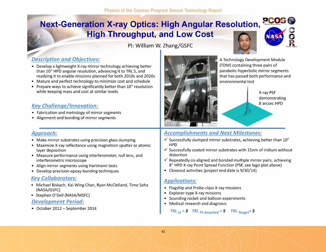
Physics of the Cosmos Program Annual Technology Report
42

Physics of the Cosmos Program Annual Technology Report
43

Physics of the Cosmos Program Annual Technology Report
44
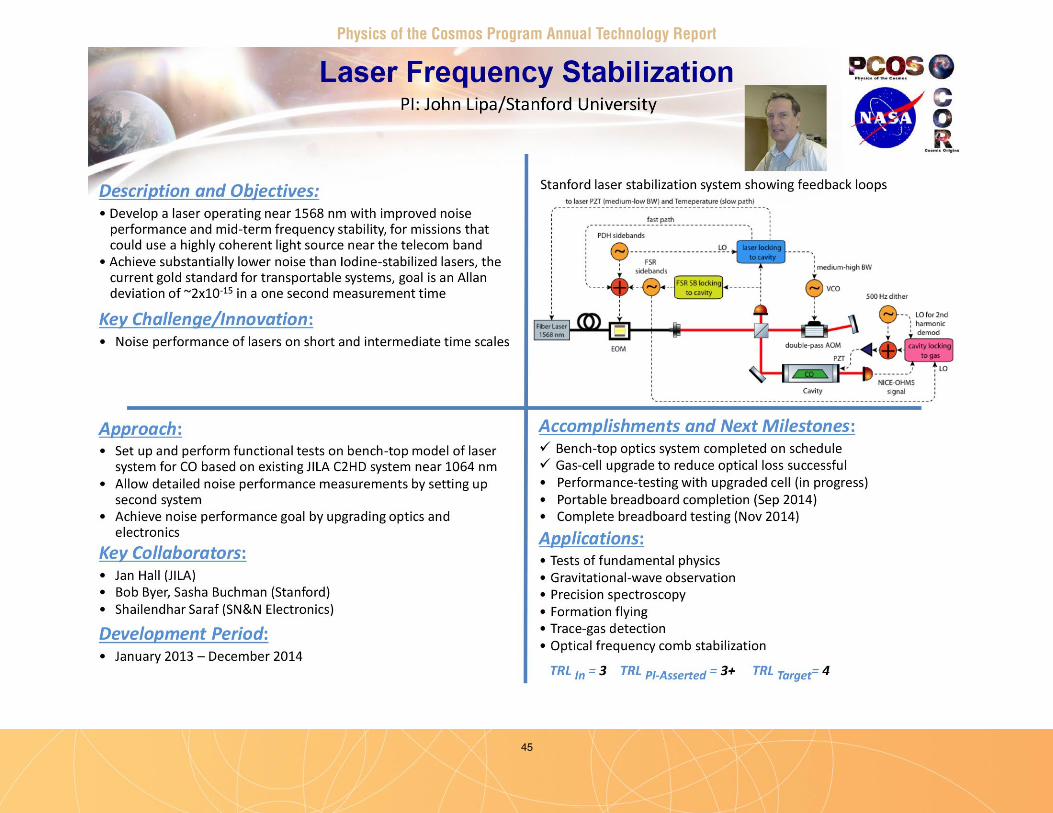
Physics of the Cosmos Program Annual Technology Report
45
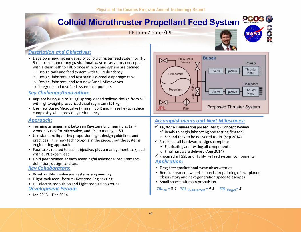
Physics of the Cosmos Program Annual Technology Report
46

Physics of the Cosmos Program Annual Technology Report
47

Physics of the Cosmos Program Annual Technology Report
48

Physics of the Cosmos Program Annual Technology Report
49
50
Physics of the Cosmos Program Annual Technology Report
Appendix BProgram Technology Development Status
Mark Bautz – “Directly Deposited Optical Blocking Filters for Imaging X-ray Detectors” . . . . . 51
Randall McEntaffer – “Off-plane Grating Arrays for Future Missions” . . . . . . . . . . . . . . . . . . . . 61
Paul Reid – “Moderate-Angular-Resolution Adjustable
Full-Shell Grazing-Incidence X-ray Optics” . . . . . . . . . . . . . . . . . . . . . . . . . . . . . . . . . . . . . 67
Mark Schattenburg – “Critical-Angle Transmission (CAT) Gratings for
High-Resolution Soft X-Ray Spectroscopy” . . . . . . . . . . . . . . . . . . . . . . . . . . . . . . . . . . . . . . 74
Caroline Kilbourne – “Demonstrating Enabling Technologies for the High-Resolution Imaging
Spectrometer of the Next NASA X-ray Astronomy Mission” . . . . . . . . . . . . . . . . . . . . . . . . . 79
William Zhang – “Next-Generation X-ray Optics:
High Angular Resolution, High Throughput, and Low Cost” . . . . . . . . . . . . . . . . . . . . . . . . . 87
Paul Reid – “Adjustable X-ray Optics with Sub-Arcsec Imaging” . . . . . . . . . . . . . . . . . . . . . . . . . .92
Jeff Livas – “Telescopes for Space-Based Gravitational-Wave Observatories” . . . . . . . . . . . . . . 100
John Lipa – “Laser Frequency Stabilization” . . . . . . . . . . . . . . . . . . . . . . . . . . . . . . . . . . . . . . 108
John Ziemer – “Colloid Microthruster Propellant Feed System” . . . . . . . . . . . . . . . . . . . . . . . . 117
William Klipstein – “Gravitational-Wave Mission Phasemeter Technology Development” . . . . 127
Jordan Camp – “Demonstration of a TRL 5 Laser System for eLISA” . . . . . . . . . . . . . . . . . . . . 131
James Bock – “Planar Antenna-Coupled Superconducting Detectors for CMB Polarimetry” . . . 132
Abstracts of New SAT Projects Starting in FY 2015 . . . . . . . . . . . . . . . . . . . . . . . . . . . . . . 142
51
Physics of the Cosmos Program Annual Technology Report
Directly Deposited Optical Blocking Filters for Imaging X-ray DetectorsPrepared by: Mark Bautz (PI; MIT Kavli Institute for Astrophysics & Space Research, MKI); S. Kissel (MKI); and K. Ryu and V. Suntharalingam (MIT Lincoln Laboratory)
SummaryWe aim to raise the Technology Readiness Level (TRL) of enhanced charge-coupled-device (CCD) detectors capable of meeting the requirements of X-ray grating spectrometers (XGS) and wide-field X-ray imaging instruments for small, medium, and large missions . Because they are made of silicon, all X-ray CCDs require blocking filters to prevent corruption of the X-ray signal by out-of-band (mainly optical and near-IR) radiation . We endeavor to replace the fragile, extremely thin, free-standing blocking filter that is current standard practice with a much more robust filter deposited directly on the detector surface .
High-performance, back-illuminated CCDs have flown with free-standing filters (e.g., one of our detectors on Suzaku) and other, relatively low-performance CCDs with directly deposited filters have flown e.g., on the X-ray Multi-mirror Mission-Newton (XMM-Newton) Reflection Grating Spectrometer . However, a high-performance, back-illuminated CCD with a directly deposited filter has not yet been demonstrated . Our effort will be the first to show such a filter can be deposited on an X-ray CCD that meets the requirements of a variety of contemplated future instruments .
This Strategic Astrophysics Technology (SAT) program began on July 1, 2012 . It is a collaboration between the MKI and MIT Lincoln Laboratory . The program is currently scheduled to end June 30, 2015 .
BackgroundThe past two decades have brought extraordinary progress in X-ray astronomy, in large measure as a result of unprecedented improvements in X-ray imaging and grating spectroscopy . Beginning with the launch of the Advanced Satellite for Cosmology and Astrophysics (ASCA) in 1993, and continuing to the present, concurrent operation of Chandra, XMM-Newton, Swift, and Suzaku, much of this success has been enabled by the X-ray photon-counting CCD . CCDs will likely remain essential to many X-ray instruments for some time to come . In fact, three missions scheduled for launch in the next few years extended ROentgen Survey with an Imaging Telescope Array (e-ROSITA), Astrosat, and Astro-H, feature these detectors . Moreover, a number of future mission concepts include instruments relying on CCDs . Such instruments address a broad range of important scientific objectives . For example, as noted recently in the X-ray Mission Concepts Study Report (XCSR) commissioned by NASA’s Program Office for the Physics of the Cosmos (PCOS) [1], several high-priority scientific questions identified by the 2010 Decadal Survey, New Worlds, New Horizons in Astronomy and Astrophysics (NWNH) [2] are best addressed by an X-ray Grating Spectrometer (XGS), which requires large-format X-ray imaging detectors . Specific science goals for an XGS are summarized in Table 1 . The report notes an XGS could be deployed either alongside an X-ray micro-calorimeter on a Probe-scale mission, or as the sole instrument in a more modest, dedicated mission . XGS technology has therefore been identified as a priority 1 (highest-priority) need in the 2012 PCOS Program Annual Technology Report [3] .
Large-format X-ray imaging detectors are also required for many missions envisaged for the Explorer program, which NWNH deemed “a crown jewel of NASA space science .” For example, an Explorer XGS has been proposed for a focused study of the warm-hot intergalactic medium [4] . Other future
Mark Bautz

52
Physics of the Cosmos Program Annual Technology Report
Explorers will exploit the power of rapid-response X-ray imaging, so clearly demonstrated by Swift, but with much wider fields of view . As noted in [5], a wide-field X-ray imager (WFI) on an agile spacecraft can address with unprecedented sensitivity a variety of important science objectives ranging from the nature of the first galaxies to high-energy time-domain astrophysics (Table 1) [5] . An especially exciting prospect is identification of sources that may be detected by ground-based gravitational-wave observatories later in this decade [6][7] .
Science Question Measurement InstrumentHow does large-scale structure evolve?
Find and characterize the missing baryons via high-resolution absorption-line spectroscopy of the Warm-hot Intergalactic Medium (WHIM)
XGS
How does matter behave at high density?
Measure the equation of state of neutron stars through spectroscopy XGS
How are black holes connected to large-scale structure?
Determine energetics and mass flows in Active Galactic Nuclei (AGN) outflows; probe hot galaxy halos via absorption spectroscopy
XGS
When did the first galaxies emerge and what were they like?
Identify high-redshift galaxies via gamma-ray bursts WFI
What new discoveries await in the time domain?
Monitor the entire sky with high sensitivity to find and study gravitational wave sources and other transients
WFI
Table 1. High-priority science drivers for future instruments featuring large-format imaging X-ray detectors (adapted from the PCOS X-ray Mission Concepts Study Report [1]). Directly deposited optical blocking filters will improve performance and reliability, while reducing cost and risk of instruments addressing these questions.
Our program aims to raise the TRL of advanced optical blocking filter (OBF) technology required for these instruments . If successful, our effort will improve instrument sensitivity, robustness, and reliability, while at the same time reducing mass, complexity, risk, and cost . Our approach is to replace the fragile, free-standing optical blocking membrane of current practice with a filter deposited directly on the detector surface . A directly deposited filter can be thinner than a free-standing one, improving instrument sensitivity . Moreover, directly deposited filters do not require the heavy, complex, and expensive vacuum housings used in current instruments, and are of course much more robust than free standing filters . The key challenge for our program is to demonstrate that blocking filters can be applied directly to the sensitive entrance surfaces of modern CCD detectors without compromising spectroscopic resolution .
To minimize cost, our program uses existing stocks of engineering-grade detectors produced for past programs at MIT Lincoln Laboratory . We apply so-called ‘back-illumination’ processing to these detectors, and then use coating facilities at Lincoln to apply blocking filters . X-ray and optical performance testing is then conducted at MKI . We have also joined forces with REgolith X-Ray Imaging Spectrometer (REXIS), an MIT student instrument for NASA’s Origins Spectral Interpretation Resource Identification Security - Regolith Explorer (OSIRIS-REx) mission, to incorporate directly deposited blocking filter technology into a flight program .
Objectives and MilestonesSilicon X-ray imaging detectors require blocking filters to prevent ambient visible and UV background light from adding noise and degrading X-ray spectral resolution . As noted above, most such detectors flown to date have used fragile, free-standing filters comprised of thin plastic substrates coated with aluminum . Free-standing filters usually must be protected from acoustic ground-handling and launch loads using heavy vacuum enclosures equipped with complex door mechanisms . This project aims to
Mark Bautz

53
Physics of the Cosmos Program Annual Technology Report
show that adequate OBFs can be deposited directly on a detector, eliminating the need for fragile, free-standing filters . To the extent they eliminate plastic films, such filters could also improve soft X-ray (E < 1 keV) detection efficiency .
A key challenge in this project is to demonstrate directly deposited OBFs provide the requisite optical blocking performance without compromising the spectral resolution of the detectors in the soft band . The latter depends critically on the electric fields present just inside the entrance surface of the detector, and these fields in turn require precisely controlled implant density profiles . Our aim is to deposit blocking filters in such a way that the surface fields are unaffected by the deposition process or the filter itself . A secondary objective is to demonstrate such filters are sufficiently robust to survive the repeated thermal cycling any such detector is likely to experience .
Our approach is to use existing CCD detectors fabricated for previous programs at MIT Lincoln Laboratory . These detectors (with some exceptions) are front-illuminated, so part of our task is to perform back-illumination processing . Good X-ray response requires molecular beam epitaxy process to treat the back (entrance) surface . We then systematically apply aluminum blocking filters of various thicknesses, and characterize both the optical blocking of the filter and the X-ray performance of the devices . Our original plan entailed four tasks:
Task 1: Select and thin existing CCID41 wafers and apply backside treatmentThe target detectors for this project (Lincoln Laboratory model CCID41, now in use in Suzaku) were stored in wafer form as front-illuminated (FI) devices (typically 4 devices to a wafer) . Using wafer-probe equipment, we identify functional devices . We then subject selected wafers to a custom back-side treatment process, involving wafer thinning and molecular beam epitaxy passivation, which has already been shown to provide good X-ray results . Selected back-illuminated (BI) devices are packaged (removed from the wafer and installed in suitable test packages) for subsequent test at MKI .
Task 2: Establish baseline X-ray performanceWe use established X-ray characterization facilities and procedures at MKI to verify suitable X-ray performance of the back-illuminated (but uncoated) devices .
Task 3: Apply filters and characterize filter-equipped devicesWe use established thin-film deposition facilities at MIT Lincoln Laboratory to deposit aluminum blocking layers, and then package and test the filter-equipped devices . Filters are applied at the wafer level, with control areas masked to allow direct comparison of filtered and unfiltered areas of each device . We contemplate three cycles of filter deposition and test (one wafer per cycle), applying a relatively thick filter in the first cycle, and then continuing, after successful test, to progressively thinner filters . In so doing we will span the range of filter thicknesses required by future instruments . All filters will be capped with a 10 nm Al
2O
3 layer to improve robustness and provide UV blocking . Both optical
rejection and X-ray spectral resolution will be measured in the characterization protocol .
Task 4: Test robustness and stabilityTo verify coating temporal stability and robustness to the repeated thermal cycling experienced by CCD detectors during instrument development and test, we will perform thermal cycling and long-term (6-8 month) stability measurements .
Soon after program start we decided to alter the sequence of the program for two reasons . First, we discovered that a number of back-illuminated devices were already available at MIT Lincoln . To make best use of these, we needed to develop a filter deposition process that would accommodate individual chips as well as full wafers . Second, we learned that the MIT team developing REXIS wished to fly
Mark Bautz

54
Physics of the Cosmos Program Annual Technology Report
Progress and AccomplishmentsAt the completion of the second year of our project, we have developed an OBF deposition process and thoroughly characterized X-ray and optical performance of back-illuminated CCDs with both thick (220 nm Al) and thin (70 nm Al) OBFs, as specified in Milestones 1-5 in Table 2 . Our principal results may be summarized as follows .
1 . We demonstrated it is feasible to deposit effective aluminum OBFs directly on high-performance back-illuminated CCDs with at most modest effect on X-ray spectral resolution .
2 . The X-ray transmission of these OBFs was measured and is consistent with theoretical expectations .3 . The visible/near-IR transmission of these OBFs was characterized . Most of the filter area provides the
expected level of attenuation, but some 1-10% of the pixels show higher than expected transmission . The pixels containing these so-called “pinholes” can have sensitivity to visible light that is ×10 to ×1000 theoretical expectations . We have evidence these pinholes are caused by irregularities on the detector surface . These irregularities, each extending over at most a few hundredths of a square micron of detector surface, seem to produce small breaks in the aluminum blocking layer . The irregularities may be caused either by intrinsic roughness of the CCD surface or by sub-micron particulate contamination .
We discuss each of these results in turn .
X-ray CCDs with directly deposited blocking filters . We decided to collaborate with REXIS because by doing so we gain the opportunity to demonstrate much higher TRL for our process than we could achieve in our original program . REXIS is scheduled for delivery in 2015; OSIRIS-REx plans a 2016 launch . Although this collaboration has entailed some re-planning, we expect to achieve our objectives as scheduled .
Major milestones and our progress in achieving them are summarized in Table 2 . We describe our progress in more detail in the following section .
Milestone at completion of: Success criteria Status as of June 20141. BI processing Wafer-probe testing of BI wafers shows:
• ≥3 wafers with functional devices; and • ≥ 10 functional devices total.
• Twelve FI wafers processed, yielding 33 devices w/at least some functionality, of which eight are allocated to REXIS • Ten other functional BI devices identified as single chips
2. X-ray test of baseline BI device
X-ray performance demonstrated per protocol specified in proposal
• Complete; X-ray performance supports program objectives
3. 1st device with thickest directly deposited filter
Packaged device delivered to MKI • Complete (220 nm Al OBF)
4. X-ray and optical testing of device with thickest filter
X-ray and optical tests done per protocol specified in proposal
• Complete; three devices with 220 nm OBF characterized
5. X-ray and optical testing of device with thinnest filter
X-ray and optical tests done per protocol specified in proposal
• Complete; two devices with 70 nm OBF characterized
6. Thermal cycle test X-ray and optical tests done per protocol specified in proposal
• Planned for year 3 with REXIS
7. Long-term stability test X-ray and optical tests done per protocol specified in proposal
• Planned for year 3 with REXIS
Table 2. Project Milestones and Status.
Mark Bautz

55
Physics of the Cosmos Program Annual Technology Report
1. Soft-X-ray spectral resolution with directly deposited blocking filtersSoft X rays (with energies below 1 keV) are photo-electrically absorbed within ~1 μm of the entrance surface of a silicon detector, so good X-ray spectral resolution requires efficient collection of photoelectrons generated in this region . Precise doping of the entrance (‘back’) surface of the detector is necessary to produce the internal electric fields required to achieve this . We aimed to determine whether a metal OBF layer deposited directly on this surface would affect the spectral resolution of an X-ray CCD detector . In general, we find the OBF has little effect on spectral resolution except, possibly, at the lowest X-ray energies we studied (E < 300 eV) .
Figure 1 shows pulse-height spectra from representative devices . The back surfaces of these detectors were treated with MIT Lincoln Laboratory’s molecular-beam epitaxy (MBE) process . One device has no OBF, and the other two have directly deposited aluminum OBFs with thicknesses of 70 nm and 220 nm, respectively . Identical exposure times to the same radioactive X-ray source were used to obtain the spectra . The source produces characteristic lines of C-K, V-L, O-K, and F-K, with energies ranging from 277 eV to 677 eV . As expected, X-ray absorption in the filters reduces the amplitudes of the lower energy peaks . The figure also shows the OBFs produce relatively little change in the shapes and widths of the line response functions .
Table 3 lists typical peak widths (full-width at half-maximum, or FWHM) obtained from the different output nodes on each device . At 677 eV, all devices produce symmetrical peaks with essentially the same widths . At 525 eV, all peak widths are also quite comparable, given the expected systematic measurement uncertainties (roughly 10% of peak width) . The spectral resolution of all devices degrades to some extent at the lowest energies, and in each, the response at 277 eV shows a clear low-energy tail . We hypothesize the tail is a consequence of the relatively thick (20 nm) MBE layer applied in fabricating these devices . The FWHM at 277 eV is about 25% larger on the device with the thicker OBF than it is in the other two devices . The pre-OBF-deposition performance of this device is not known, so this difference can be regarded as an upper limit on the amount of low-energy broadening attributable to the OBF . Note that the unfiltered device and the device with the 70 nm-thick OBF show the same response widths at all three energies .
2. X-ray transmission of OBFsMeasured X-ray transmission of a 70 nm-thick OBF is compared to expectations in Fig . 2, with generally good agreement . The data were obtained from a device (53-1-4-2) on which only part of the detector was covered by the OBF . Both covered and uncovered regions were exposed to a multi-line source like the one used to produce the spectra in Fig . 1, and transmission was determined from the line fluxes measured in the two regions . The red circles show measurements obtained by fitting Gaussian profiles to the data . Green crosses show fluxes obtained by summing over a spectral region within ±3 standard deviations of line centers . The two methods agree reasonably well, except at the very lowest energy measured (183 eV) where the line profiles are distinctly non-Gaussian . Similarly good agreement between measurements and expectations is obtained with 200 nm OBFs (see [8] for details) .
3. Visible/near-IR transmission of directly deposited OBFsFigure 3 shows the measured visible-band quantum efficiency (QE) of a device with a directly deposited blocking filter with a nominal thickness of 70 nm . The measurements agree reasonably well with a simple model of an aluminum layer over a thick silicon substrate . The aluminum thickness in the model has been adjusted to 63 nm to fit the data . The model assumes perfect internal CCD QE, which is certainly an overestimate redward of 600 nm, as the (thinned) detector’s sensitive volume (depletion region) is nominally 45 microns thick . A more sophisticated model, incorporating an accurate treatment of the internal detector efficiency, is clearly required to represent the data in the near-IR spectral band . The present results may indicate the OBF is somewhat more transparent in this spectral band than the simple model predicts .
Mark Bautz

56
Physics of the Cosmos Program Annual Technology Report
Visible-band, flat-field exposures with both 220 nm-thick and 70 nm-thick OBFs show “pinhole-like” regions of relatively high transmission, as illustrated in Fig . 4 . The image on the left of the figure shows pinholes in a 220 nm-thick OBF . The device was exposed to a fluence of 1 .3×106 photons/pixel at 800 nm . A histogram of the 440,000 pixel amplitudes in the image is shown in the right panel . The expected transmission of this OBF is less than 10-9, so if the OBF were perfect, all pixels would have
Fig. 1. Soft X-ray response of a device with no OBF (black) and with directly deposited aluminum filters 70 nm (red) and 200 nm (green) thick. The filters have very little effect on spectral resolution.
Line Energy (eV) Line width without OBF FWHM (eV) Line width with 70 nm OBF FWHM (eV)
Line width with 220 nm OBF FWHM (eV)
277 59-74 62 75-92525 70-92 68 76-96677 61-78 59 61-75
Note: Data from device 53-1-4-3 (no OBF), 53-1-4-2 (70 nm-thick OBF) and device 53-1-7-1 (220 nm-thick OBF).
Table 3. Spectral resolution for devices without and with a directly deposited OBF.
Mark Bautz

57
Physics of the Cosmos Program Annual Technology Report
As discussed in detail in [8], we believe the pinholes are caused by surface irregularities present on the detector surface before the OBF is deposited . Several lines of evidence support this explanation . First, test coatings on quartz substrates do not show pinholes . Second, as shown in Fig . 5, scanning electron micrographs of deposited OBFs show texture with sizes (< 100 nm) and spatial density consistent with the observed number and transmission of pinholes . Third, the number of pinholes is dramatically reduced if an optically transparent, 1μm-thick layer of photoresist is deposited on the detector surface before the aluminum OBF layer is deposited . Although such an interlayer is opaque to soft X-rays and so could not be used on an X-ray sensor, this result does suggest there are no fundamental limitations to fabrication of a pinhole-free, directly deposited OBF .
Fig. 2. Measured (points) and modeled X-ray transmission of 70 nm thick aluminum OBF. Red and green points obtained with different X-ray measurement methods discussed in the text.
Mark Bautz
zero amplitude, modulo the readout noise with root-mean-square (rms) width of a few electrons . The histogram shows 99% of pixels are in fact consistent with zero amplitude, and about 1% of pixels are affected by pinholes with transmission ranging from about 10-6 to as high as 5×10⁻⁴ .

58
Physics of the Cosmos Program Annual Technology Report
Mark Bautz
Fig. 3. Visible/near IR QE of a CCD with a directly deposited blocking filter. Nominal filter thickness is 70 nm. The points are measured values; the line is a simple model of a 63 nm-thick OBF. Note: Data from device 53-1-4-2.

59
Physics of the Cosmos Program Annual Technology Report
Path ForwardIn the final year of our program, we plan to do the following (milestone numbers refer to Table 2) .
• Subject selected devices to thermal cycle tests simulating typical ground-handling and flight conditions . The detailed protocols are discussed in our proposal (Milestone 6) .
• Devise and execute a long-term (6 – 8 months) stability test to investigate the robustness of our OBFs . We will focus in particular on the stability of pinholes (Milestone 7) .
Mark Bautz
Fig. 5. Scanning electron micrograph images of an OBF directly deposited on the surface of a CCD.
Fig. 4. Left: Image obtained from by CCD with a 220 nm-thick OBF illuminated with 1.3×10 6 photons/pixel of 800 nm light. Pinholes (white spots) are evident. Right: Histogram of amplitudes of the 440,000 pixels in the image on the left. While 99% of pixels are in the peak, and are consistent with zero amplitude, about 1% of pixels show transmission greater than 10-6.
60
Physics of the Cosmos Program Annual Technology Report
• Characterize REXIS engineering and flight model CCDs with OBFs deposited at the full-wafer level . These devices will ultimately be subjected to environmental tests tailored to the OSIRIS-REx mission . While not originally part of our project, this work will provide the basis for validation of directly deposited OBFs at a very high level of technical readiness .
References[1] X-ray Community Science Team, X-ray Science Support Team, and X-ray Engineering Support Team,
(August 2012) “X-ray Mission Concepts Study Report,” [Online] (http://pcos .gsfc .nasa .gov/physpag/X-ray_Mission_Concepts_Study_Report-Final .pdf)
[2] National Academy of Science, Board on Physics and Astronomy (2010) “New Worlds, New Horizons in Astronomy and Astrophysics,” [Online] (http://www .nap .edu/catalog .php?record_id=12951)
[3] NASA Physics of the Cosmos Program Office (October 2012) “NASA Physics of the Cosmos Program Annual Technology Report,” [Online] (http://pcos .gsfc .nasa .gov/technology/2012_PCOS_PATR_Final_101612 .pdf)
[4] C . Lillie et al., “The Warm-Hot Intergalactic Medium Explorer (WHIMEx) mission,” Proc . SPIE , Vol . 8145, pp . 81450C-81450C-14, 2011 .
[5] N . Gehrels, S . Barthelmy, and J . Cannizzo, “Time-Domain Astronomy with Swift, Fermi and Lobster,” Proc . IAU, Vol . 285, pp . 41-46, 2012 .
[6] Laser Interferometer Gravitational-wave Observatory (LIGO) Scientific Collaboration, “Predictions for the rates of compact binary coalescences observable by ground-based gravitational-wave detectors,” Classical and Quantum Gravity, Vol . 27, p . 173001, 2010 .
[7] B .D . Metger and E . Berger, “What is the Most Promising Electromagnetic Counterpart of a Neutron Star Binary Merger?” Astrophysical Journal, Vol . 746, p . 48, 2012 .
[8] K . Ryu et al., “Development of CCDs for REXIS on OSIRIS-REx,” 2014 Proc . SPIE 9144, in press .
For additional information, contact Mark Bautz: [email protected]
Mark Bautz

61
Physics of the Cosmos Program Annual Technology Report
Off-plane Grating Arrays for Future MissionsPrepared by: Randall L. McEntaffer (University of Iowa)
SummaryHigh-resolution X-ray spectroscopy is a scientifically relevant technology capable of addressing many key science objectives such as detecting the large fraction of missing baryons thought to exist in the warm-hot phase of the intergalactic medium . Such observations will require a combination of high effective area and high spectral resolving power at energies below ~2 keV . These measurements can be enabled for future missions using an X-ray grating spectrometer (XGS) incorporating large-area optics, high-resolution gratings, and sensitive CCD cameras . Technology development efforts are occurring in each of these key areas in order to increase the readiness of such spectrometers .
Here, we describe progress made during the two-year technology development effort for an Off-Plane X-ray Grating Spectrometer (OP-XGS) [1], during the calendar years 2012-2013 under a Strategic Astrophysics Technology (SAT) program . Our team consists of collaborators from academic institutions (University of Iowa and University of Colorado), NASA centers (Goddard Space Flight Center, GSFC, and Marshall Space Flight Center, MSFC), as well as an international partner (the Open University, UK) . We are investigating a grating fabrication method using standard semiconductor industry lithography approaches . We also assess the performance of the resulting gratings, and the challenges of incorporating them into aligned assemblies . During this program, we made significant advances in each of these areas . The results from the first year of our study include identification of the preferred fabrication technique involving electron-beam lithography, measurement of the high grating efficiency resulting from this fabrication technique, and initial analysis of the necessary alignment tolerances . During the second year, we measured high spectral resolving power, tested alignment capabilities in a prototype mount, and identified a method of fabricating a mount capable of meeting alignment tolerances mechanically . Once complete, our development effort will position the OP-XGS for flight system development upon identification of the next spectroscopic X-ray observatory .
BackgroundThe purpose of this study is to advance high-resolution X-ray spectroscopy and its application in future NASA missions . Specifically, the project will concentrate on improving the Technology Readiness Level (TRL) of off-plane reflection grating spectroscopy for soft X-rays (0 .2 – 1 .5 keV) . This technology has applications in a variety of NASA missions from suborbital rockets, to Explorer class missions, to large observatories . It was baselined for a previously proposed Explorer mission, the Warm-Hot Intergalactic Medium Explorer (WHIMEx), and was considered for many other mission concepts such as the Advanced X-ray Spectroscopic Imaging Observatory (AXSIO), the Notional X-ray Grating Spectrometer (N-XGS), and the Square Meter Arcsecond Resolution Telescope for X-rays (SMART-X) . Currently, an OP-XGS forms the backbone of an Explorer mission concept, Arcus, slated for submission in response to the 2014 Explorer AO .
Soft X-ray grating spectrometers with high throughput and high spectral resolving power can address many top science questions such as:
• What controls the mass-energy-chemical cycles within galaxies?• How do baryons cycle in and out of galaxies, and what do they do while they are there?• What are the flows of matter and energy in the circumgalactic medium?• How do black holes work and influence their surroundings?• How do massive stars end their lives?• What controls the masses, spins, and radii of compact stellar remnants?
Randall McEntaffer

62
Physics of the Cosmos Program Annual Technology Report
These science questions can be addressed with high-quality X-ray spectra as specifically stated in the 2010 Decadal Survey, New Worlds, New Horizons in Astronomy and Astrophysics (NWNH) . At the lowest energies, the most efficient method of obtaining high spectral resolving power is grating spectrometers . High-resolution spectra could address a number of important astrophysical goals such as studying the dynamics of clusters of galaxies, determining how elements are created in the explosions of massive stars, and revealing most of the “normal” matter in the universe that is currently thought to be hidden in hot gas filaments stretching between galaxies .
To achieve these science goals, the OP-XGS must be capable of producing spectral resolving powers better than 1500 (λ/δλ), with high throughput over the soft X-ray energy band, 0 .2 - 1 .5 keV . The major limiting factor is meeting the spectral resolving power requirement . In the context of off-plane reflection gratings, this requires customization of the groove profile to obtain blazed facets with high groove density that varies along the groove direction . Holographic recording of the groove profile has been the standard method for off-plane grating fabrication, but has limitations in obtaining the desired custom profile . We are developing a new fabrication method using common lithographic techniques borrowed from the semiconductor industry . Electron beam (e-beam) lithography enables tighter control over the groove profile during recording, while various etching steps can be used to shape the facets to the desired blaze . An optimal groove profile will cancel any grating-induced aberrations to the telescope focus while maximizing throughput and resolving power over our wavelength band of interest . Once fabricated, the gratings will be aligned into an array to increase the overall spectrometer collecting area . Alignment tolerances must be met so that every spectrum from every grating overlaps at the focal plane without alignment-induced distortion . We have analyzed our alignment tolerances and are currently developing medium-fidelity mounts to position gratings and measure their placement . Therefore, at the highest level, our development plan can be described as three main paths:
1 . A study of the custom grating fabrication to increase groove profile fidelity;2 . A study of alignment methods for populating large arrays of gratings; and3 . A course of testing to verify performance at each development stage .
Progress made during the development of the OP-XGS has been detailed in the three previous Program Annual Technology Reports (PATRs) of the Physics of the Cosmos (PCOS) Program . The PCOS program identified X-ray reflection gratings as a critical technology for development in this decade to address X-ray science goals . In this role, we also contributed a development roadmap detailing the efforts and milestones necessary to advance the OP-XGS to flight readiness, incorporated into the most recent PCOS Technology Development Roadmap (TDR) .
Objectives and MilestonesThe development of an OP-XGS for future X-ray missions follows a set of objectives defined by the three main programs that have supported our studies over the past 2 .5 years .
• An SAT grant to study grating fabrication techniques, grating substrate and module mount material, and grating alignment;
• A Roman Technology Fellowship (RTF) to refine fabrication and replication of medium- to high-fidelity gratings; and
• An Astronomy and Physics Research and Analysis (APRA) grant to launch a suborbital rocket payload incorporating slumped glass X-ray optics, an aligned array of off-plane gratings, and a soft X-ray-sensitive CCD camera .
Randall McEntaffer
63
Physics of the Cosmos Program Annual Technology Report
The synergy between these projects allows for an extensive and detailed set of OP-XGS development project milestones, as follows .
1 . Grating fabrication trade study; compare holographic and e-beam lithography groove recording techniques – completed in the 1st quarter of 2012;
2 . Initial grating fabrication trials; used e-beam lithography to write the groove profile at the correct density with an accurate line space variation – completed early in the 2nd quarter of 2012;
3 . Performance-test initial gratings:a . Test grating diffraction efficiency over 0 .2-1 .5 keV band – completed in the 2nd quarter of 2012; andb . Test grating spectral resolving power – completed in the 3rd quarter of 2012 .
4 . Quantify alignment tolerances – completed in the 1st quarter of 2013;
5 . Fabricate low-fidelity module mount and quantify performance in placement and metrology – completed in the 2nd quarter of 2013;
6 . Perform module mount trade study; compare placement via precision actuators vs . placement directly onto precision ground bosses – planned for 3rd/4th quarter of 2013;
7 . Design medium-fidelity module mount – planned for 3rd/4th quarter of 2013, dependent on module mount trade study;
8 . Fabricate a blazed master grating – began in the 1st quarter of 2013, ongoing development throughout project;
9 . Performance-test blazed master grating – initial results obtained in the 1st quarter of 2013, extensive testing planned for the last two quarters of 2014;
10 . Design a large-format mask for large-format grating fabrication – completed in the 1st quarter of 2013;
11 . Fabricate medium-fidelity grating mount – planned for the 2nd/3rd quarter of 2014;
12 . Align multiple gratings into mount – planned for the 2nd/3rd quarter of 2014;
13 . Performance and environmental testing of medium-fidelity module of aligned gratings – planned for the 3rd quarter of 2014;
14 . Perform grating substrate trade study (if applicable) – planned for the 4th quarter of 2014;
15 . Fabricate large-format master – planned for the 3rd/4th quarter of 2014;
16 . Develop replication technique (if applicable) – planned for the 4th quarter of 2014;
17 . Performance-test large-format blazed gratings – planned for 2015;
18 . Performance-test replicas (if applicable) – planned for 2015;
19 . Finalize rocket module design – planned for the 1st quarter of 2015;
20 . Co-align and performance/environmental-test prototype rocket optics/grating modules – planned for the 2nd/3rd quarter of 2015;
21 . Incorporate optics and grating arrays into a suborbital rocket payload – planned for early 2016;
22 . Integrate with system architecture and CCD camera – throughout 2016; and
23 . Launch suborbital OP-XGS – planned for early 2017 .
Since the last PATR, we have edited/deleted several of our milestones and delayed many others . Much of this was due to the end of the previous SAT project without the renewal proposal being accepted . Furthermore, it is currently unclear if developments involving replicas are necessary . These include developing the replication technique and performance-testing replicas, as well as influencing the grating-substrate trade study . This is because it may be beneficial to fabricate each grating individually via an industrialized version of our fabrication technique, as opposed to replicating a master into epoxy, which may affect groove profile fidelity . This issue will be addressed during our ongoing
Randall McEntaffer

64
Physics of the Cosmos Program Annual Technology Report
fabrication study . It is important to note that one milestone has been advanced – the fabrication of a higher-fidelity module mount, due to the need for performance/systems testing in support of the Arcus Explorer proposal [2] .
Progress and AccomplishmentsOur previous accomplishments under the SAT program are described in detail in the 2012 and 2013 PATRs . In addition, we reported on our successful performance-testing of prototype gratings for high throughput and spectral resolving power [1] and determined the analytical alignment tolerances for a representative off-plane grating array [3] .
To prove that we can meet the necessary alignment tolerances, we developed a custom alignment bench utilizing precision picomotors and grating metrology based on Shack-Hartmann sensor measurements . We have shown the tolerances can be realized in the lab using this setup . Using these results, we are planning to populate this “active” mount with aligned gratings and performance-test the assembly in late 2014 . In addition to this active alignment methodology, we are also investigating precision machining of the module mount to directly address each grating with no actuation necessary . We are working with General Dynamics (formerly Axsys Technologies) and have formulated a design . The module is being fabricated and alignment tolerances will be verified this year . We will compare the relative ease of alignment of the two methods, especially as it affects the integration and testing phase of a large-scale mission .
Since our previous reporting, we have also extended our track of performance-testing the prototype gratings for spectral resolving power, the largest hurdle for qualifying grating spectrometers for future missions . During previous tests at MSFC (in late 2012), we were limited by source diffusivity; the optics were capable of resolving the electron impact spot on the X-ray source anode . Therefore, while we were able to measure the theoretical resolution of 900 (λ/Δλ) for 1st order Mg Kα (1 .25 keV), higher-order resolutions did not scale accordingly and were limited to 1300 . We then moved testing to the GSFC facility (in late 2013/early 2014) where the much longer 600 m beam line allowed for a discrete source . This resulted in a new record for spectral resolving power for a reflection grating with a measured value of ~2100 at 3rd order Mg Kα (Fig . 1) . However, we found that this number was limited by the stability of the CCD which is cantilevered from the main optics chamber and simply supported . Since this measurement, the Stray Light Facility at MSFC has been upgraded to address the previous source issue (during the 2nd quarter of 2014) while the large instrument chamber allows for maximal stability of system components . Preliminary analysis of data just obtained in the 3rd quarter of 2014 shows excellent results . Using the Al Kα line, we were able to detect all orders from -6th to +6th . At 6th order, the spectral line spread function was dominated by the natural width of the Al Kα
1 and Kα
2 lines
which are only separated by 0 .43 eV . This demonstrated another record for X-ray spectral resolving power, at 3250 .
In parallel, we have been constantly progressing on our RTF-supported grating fabrication study . While we have produced blazed gratings, our methods require improved consistency to produce quality gratings with high production efficiency . Since our previous report, we optimized several areas, including mask production, reactive ion etch recipe, wet etch recipe, and scanning electron micrograph (SEM) qualification . We recently succeeded in repeatably producing blazed gratings using 100 wafers (Fig . 2) . In this SEM, the normal of the wafer is aligned with the <100> direction, pointing up in the image . The <111> plane is oriented at an angle of 54 .7° relative to the <100> direction, resulting in the triangular side walls between grating grooves after KOH etching . Repeatable reproduction of these features qualifies the etch recipes and allows us to move forward to etching the more expensive off-axis cut wafers . Production of the final blazed profile is planned for the 3rd quarter of 2014, with performance testing to follow .
Randall McEntaffer

65
Physics of the Cosmos Program Annual Technology Report
Path ForwardIn the coming years, our efforts will concentrate on achieving the list of milestones presented above . The overarching goal will be to fabricate and test populated arrays of aligned gratings . To reach this goal we must fabricate large-format blazed gratings, fabricate higher-fidelity mounts, align gratings to
Fig. 1. Left: Locations of individual X-ray photons at the focal plane constructed from 60 individual photon-counting CCD frames. Right: Histogram of photon X-axis pixels in the right panel. The full-width at half-maximum (FWHM) of the line, determined by the best Gaussian fit (red line), corresponds to a resolution of 2100.
Fig. 2. SEM image of a cleaved <100> wafer following our etch recipe. The trapezoidal groove features with smooth sidewalls are created by KOH etching to the <111> planes.
Randall McEntaffer

66
Physics of the Cosmos Program Annual Technology Report
within tolerances, and test the aligned assemblies . Currently, we are funded to study the fabrication of gratings under the RTF program, and to align fabricated gratings into arrays under the APRA rocket program . We are currently not funded to increase the TRL of off-plane gratings via a dedicated program specifically aimed at reducing risks of future NASA space missions . Such a program would continue to develop alignment methodologies and module mounts, while also supporting the necessary performance and environmental testing to reach TRL 6 in the context of these future missions . Therefore, our path forward is currently dedicated to the RTF and rocket programs . While developments needed for the rocket program are planned, an in-depth study applicable to future missions is beyond the scope of the current suite of programs, and therefore has been proposed in the latest SAT solicitation . The synergy between our SAT, RTF, and APRA programs has allowed a clear definition of the path forward, and must be maintained to accomplish our goals .
References[1] McEntaffer, R . L ., DeRoo, C ., Schultz, T ., Gantner, B ., Tutt, J ., Holland, A ., O’Dell, S ., Gaskin, J .,
Kolodziejczak, J ., Zhang, W . W ., Chan, K .-W ., Biskach, M ., McClelland, R ., Iazikov, D ., Wang, X ., and Koecher, L ., “First results from a next-generation off-plane X-ray diffraction grating,” Experimental Astronomy, 36, 389, 17 pages, 2013 .
[2] Allured, R . & McEntaffer, R . L ., “Analytical Alignment Tolerances for Off-Plane Reflection Grating Spectroscopy,” Experimental Astronomy, 36, 661, 17 pages, 2013 .
[3] Smith, R . K ., et al., “The X-ray grating explorer: an ISS-attached high-resolution X-ray grating spectrometer,” Proc . SPIE, 9144, in press, 2014 .
For additional information, contact Randall McEntaffer: [email protected]
Randall McEntaffer
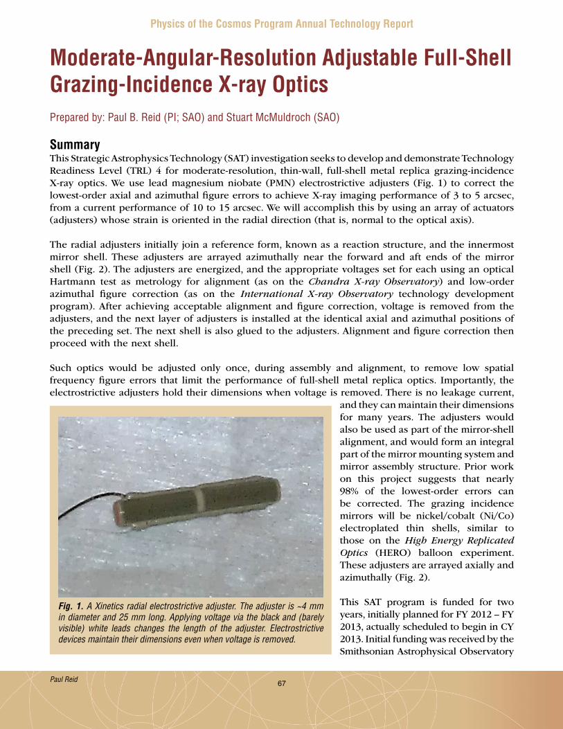
67
Physics of the Cosmos Program Annual Technology Report
Moderate-Angular-Resolution Adjustable Full-Shell Grazing-Incidence X-ray OpticsPrepared by: Paul B. Reid (PI; SAO) and Stuart McMuldroch (SAO)
SummaryThis Strategic Astrophysics Technology (SAT) investigation seeks to develop and demonstrate Technology Readiness Level (TRL) 4 for moderate-resolution, thin-wall, full-shell metal replica grazing-incidence X-ray optics . We use lead magnesium niobate (PMN) electrostrictive adjusters (Fig . 1) to correct the lowest-order axial and azimuthal figure errors to achieve X-ray imaging performance of 3 to 5 arcsec, from a current performance of 10 to 15 arcsec . We will accomplish this by using an array of actuators (adjusters) whose strain is oriented in the radial direction (that is, normal to the optical axis) .
The radial adjusters initially join a reference form, known as a reaction structure, and the innermost mirror shell . These adjusters are arrayed azimuthally near the forward and aft ends of the mirror shell (Fig . 2) . The adjusters are energized, and the appropriate voltages set for each using an optical Hartmann test as metrology for alignment (as on the Chandra X-ray Observatory) and low-order azimuthal figure correction (as on the International X-ray Observatory technology development program) . After achieving acceptable alignment and figure correction, voltage is removed from the adjusters, and the next layer of adjusters is installed at the identical axial and azimuthal positions of the preceding set . The next shell is also glued to the adjusters . Alignment and figure correction then proceed with the next shell .
Such optics would be adjusted only once, during assembly and alignment, to remove low spatial frequency figure errors that limit the performance of full-shell metal replica optics . Importantly, the electrostrictive adjusters hold their dimensions when voltage is removed . There is no leakage current,
and they can maintain their dimensions for many years . The adjusters would also be used as part of the mirror-shell alignment, and would form an integral part of the mirror mounting system and mirror assembly structure . Prior work on this project suggests that nearly 98% of the lowest-order errors can be corrected . The grazing incidence mirrors will be nickel/cobalt (Ni/Co) electroplated thin shells, similar to those on the High Energy Replicated Optics (HERO) balloon experiment . These adjusters are arrayed axially and azimuthally (Fig . 2) .
This SAT program is funded for two years, initially planned for FY 2012 – FY 2013, actually scheduled to begin in CY 2013 . Initial funding was received by the Smithsonian Astrophysical Observatory
Fig. 1. A Xinetics radial electrostrictive adjuster. The adjuster is ~4 mm in diameter and 25 mm long. Applying voltage via the black and (barely visible) white leads changes the length of the adjuster. Electrostrictive devices maintain their dimensions even when voltage is removed.
Paul Reid
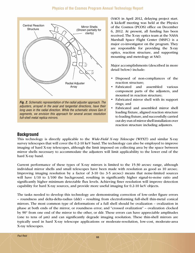
68
Physics of the Cosmos Program Annual Technology Report
(SAO) in April 2012, delaying project start . A kickoff meeting was held at the Physics of the Cosmos (PCOS) office on December 6, 2012 . At present, all funding has been received . The X-ray optics team at the NASA Marshall Space Flight Center (MSFC) is a major co-investigator on the program . They are responsible for providing the X-ray optics, reaction structure, and supporting mounting and metrology at SAO .
Major accomplishments (described in more detail below) include:
• Disposed of non-compliances of the reaction structure;
• Fabricated and assembled various component parts of the adjusters, and mounted in reaction structure;
• Fabricated mirror shell with its support rings; and
• Fabricated and assembled mirror shell loading fixture, aligned reaction structure to loading fixture, and successfully carried out dry-run of mirror shell installation over reaction structure including adjusters .
BackgroundThis technology is directly applicable to the Wide-Field X-ray Telescope (WFXT) and similar X-ray survey telescopes that will cover the 0 .2-10 keV band . The technology can also be employed to improve imaging of hard X-ray telescopes, although the limit imposed on collecting area by the space between mirror shells necessary to accommodate the adjusters will limit applicability to the lower end of the hard X-ray band .
Current performance of these types of X-ray mirrors is limited to the 15-30 arcsec range, although individual mirror shells and small telescopes have been made with resolution as good as 10 arcsec . Improving imaging resolution by a factor of 3-10 (to 3-5 arcsec) means that noise-limited sources will have 1/10 to 1/100 the background, resulting in significantly higher signal-to-noise ratio and significantly higher minimum detectable flux levels . Achieving finer resolution will improve detection capability for hard X-ray sources, and provide more useful imaging for 0 .2-10 keV objects .
The tasks needed to develop this technology are demonstrating correction of low-order figure errors – roundness and delta-delta-radius (ddr) – resulting from electroforming full-shell thin-metal conical mirrors . The most common type of deformations of a full shell should be ovalization – ovalization in phase at both ends of the mirror, or roundness error; and “crossed ovalization” – ovalization clocked by 90° from one end of the mirror to the other, or ddr . These errors can have appreciable amplitudes (one to tens of µm) and can significantly degrade imaging resolution . These thin-shell mirrors are typically used in hard X-ray telescope applications or moderate-resolution, low-cost, moderate-area X-ray telescopes .
Fig. 2. Schematic representation of the radial adjuster approach. The adjusters, arrayed in the axial and tangential directions, have their long axes in the radial direction. While the schematic shows Gen-X segments, we envision this approach for several arcsec resolution full-shell metal replica mirrors.
Paul Reid

69
Physics of the Cosmos Program Annual Technology Report
To demonstrate this approach, the major tasks are:
1 . Producing a thin (0 .1 to 0 .2 mm wall thickness) electroplated full-shell mirror;2 . Measuring the shape of that mirror, particularly its out-of-roundness;3 . Mounting and correcting it using the radial adjusters; and4 . Re-measuring .
The initial experiment would be with a single shell mounted to a reaction structure, and the follow-on experiment will use two shells mounted concentrically to the reaction structure . A coordinate measuring machine (CMM) will be used for the first measurements . As accuracy improves, the Centroid Detector Assembly (CDA) – a pupil-scanning Hartmann tester – will be used for higher-accuracy measurements .
Objectives and MilestonesThe major tasks and milestones are shown below in the updated project schedule (Fig . 3) . SAO started this project in April 2012 . As of last year’s Program Annual Technology Report (PATR), we had fabricated the reaction structure including measuring its compliance with requirements, and developed a major simplification to our approach that reduced the number of adjusters from 64 to 16 . The updated schedule accounts for the program delay as well as the projected improved schedule .
Progress and AccomplishmentsSignificant progress was achieved in developing the assembly/adjustment hardware in the past year .
• Measurement of the reaction structure revealed several non-compliances in its machined dimensions . We determined the non-compliances were not critical and will not adversely impact system operation or test . Therefore, we agreed to final acceptance of the reaction structure .
• Detail parts for actuator assemblies (Fig . 4 shows adjuster assembly) were fabricated and assembled .
The actuator assemblies were mounted in the reaction structure, and coupled to their coarse adjustment positioners (Fig . 5) . The coarse positioners are used to both nominally position the fine piezoresistive adjusters in the center of their range, and for mirror installation, to back the adjusters into the support
Fig. 3. Revised program schedule.
Paul Reid

70
Physics of the Cosmos Program Annual Technology Report
Fig. 4. Piezoresistive adjuster assembly. Bonding pads are connected to the adjuster via thin wire flexures.
Fig. 5. Left: The completed reaction structure with installed micro and coarse adjusters. The reaction structure sits on three alignment positioning stages used to level it to gravity. Right top: A close-up of the lower, remote coarse adjusters. Right bottom: A close-up of the upper, manually operated coarse adjusters.
structure a safe distance so the mirror shell does not hit any adjusters during installation . The reaction structure was also mounted on its positioning stages used to level the reaction structure to gravity, and enable it to be centered to the mirror shell . Note that different coarse positioning stages are used
Paul Reid
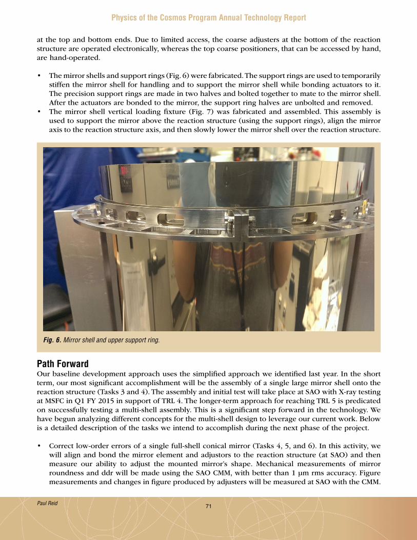
71
Physics of the Cosmos Program Annual Technology Report
at the top and bottom ends . Due to limited access, the coarse adjusters at the bottom of the reaction structure are operated electronically, whereas the top coarse positioners, that can be accessed by hand, are hand-operated .
• The mirror shells and support rings (Fig . 6) were fabricated . The support rings are used to temporarily stiffen the mirror shell for handling and to support the mirror shell while bonding actuators to it . The precision support rings are made in two halves and bolted together to mate to the mirror shell . After the actuators are bonded to the mirror, the support ring halves are unbolted and removed .
• The mirror shell vertical loading fixture (Fig . 7) was fabricated and assembled . This assembly is used to support the mirror above the reaction structure (using the support rings), align the mirror axis to the reaction structure axis, and then slowly lower the mirror shell over the reaction structure .
Path ForwardOur baseline development approach uses the simplified approach we identified last year . In the short term, our most significant accomplishment will be the assembly of a single large mirror shell onto the reaction structure (Tasks 3 and 4) . The assembly and initial test will take place at SAO with X-ray testing at MSFC in Q1 FY 2015 in support of TRL 4 . The longer-term approach for reaching TRL 5 is predicated on successfully testing a multi-shell assembly . This is a significant step forward in the technology . We have begun analyzing different concepts for the multi-shell design to leverage our current work . Below is a detailed description of the tasks we intend to accomplish during the next phase of the project .
• Correct low-order errors of a single full-shell conical mirror (Tasks 4, 5, and 6) . In this activity, we will align and bond the mirror element and adjustors to the reaction structure (at SAO) and then measure our ability to adjust the mounted mirror’s shape . Mechanical measurements of mirror roundness and ddr will be made using the SAO CMM, with better than 1 µm rms accuracy . Figure measurements and changes in figure produced by adjusters will be measured at SAO with the CMM .
Fig. 6. Mirror shell and upper support ring.
Paul Reid
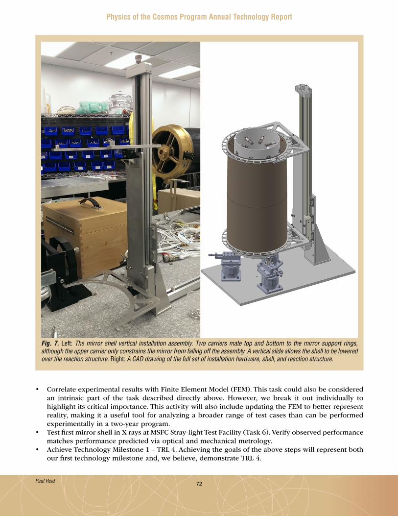
72
Physics of the Cosmos Program Annual Technology Report
• Correlate experimental results with Finite Element Model (FEM) . This task could also be considered an intrinsic part of the task described directly above . However, we break it out individually to highlight its critical importance . This activity will also include updating the FEM to better represent reality, making it a useful tool for analyzing a broader range of test cases than can be performed experimentally in a two-year program .
• Test first mirror shell in X rays at MSFC Stray-light Test Facility (Task 6) . Verify observed performance matches performance predicted via optical and mechanical metrology .
• Achieve Technology Milestone 1 – TRL 4 . Achieving the goals of the above steps will represent both our first technology milestone and, we believe, demonstrate TRL 4 .
Fig. 7. Left: The mirror shell vertical installation assembly. Two carriers mate top and bottom to the mirror support rings, although the upper carrier only constrains the mirror from falling off the assembly. A vertical slide allows the shell to be lowered over the reaction structure. Right: A CAD drawing of the full set of installation hardware, shell, and reaction structure.
Paul Reid

73
Physics of the Cosmos Program Annual Technology Report
• Stability is always a concern for a space-based instrument . We will measure the stability of the electrostrictive devices, which should maintain their dimensions after voltage is removed (this condition is called electrically clamped, as charges are not free to move within the device) . We will provide some limited testing of this by introducing deformations, removing voltage, and monitoring the mirror shape over time (part of Task 6) .
Additional funding is required to accomplish tasks 7 – 10, described below .
• Fabricate a second, smaller, 15 cm reaction structure with an appropriately scaled mirror (Tasks 7 and 8) . Currently, we are developing our processes using a relatively large reaction structure and mirror shell . Once successful, we will apply the lessons learned to smaller mirrors that are harder to mount and align due to their size, but are more representative of a flight-assembly geometry .
• Assemble two-shell mirror and test in X rays (Tasks 9 and 10) . First, the inner, smaller shell is mounted and aligned to the smaller reaction structure . Then, the outer shell is attached and aligned to the smaller mirror . In both cases, adjustment and alignment are verified using mechanical and optical metrology . Finally, the two-mirror shell telescope will be tested with X rays at the MSFC Stray-light Facility in support of achieving TRL 5 .
For additional information, contact Paul Reid: [email protected]
Paul Reid

74
Physics of the Cosmos Program Annual Technology Report
Critical-Angle Transmission (CAT) Gratings for High-Resolution Soft X-Ray SpectroscopyPrepared by: Mark L. Schattenburg (PI; MIT), Ralf K. Heilmann (MIT), and Alex R. Bruccoleri (Izentis)
SummaryCAT gratings combine the advantages of traditional phase-shifting transmission gratings – relaxed alignment and figure tolerances, low mass, transparency at high energies; and blazed reflection gratings – high diffraction efficiency, high resolving power due to utilization of higher diffraction orders . In combination with grazing incidence X-ray mirrors and CCD detectors, they promise a 5- to 10-fold increase in efficiency and a 3- to 5-fold improvement in resolving power over existing X-ray grating spectrographs [1] . Development of CAT grating fabrication technology has been supported by NASA under the Strategic Astrophysics Technology (SAT) program since January 2012 .
The past year saw the first X-ray test of a freestanding CAT grating membrane fabricated with a combination of an advanced deep reactive-ion etch (DRIE) and a potassium hydroxide (KOH) polishing step, demonstrating that the combined dry and wet etch techniques simultaneously lead to the predicted blazing and large grating open area fraction .
BackgroundAbsorption and emission line spectroscopy, with the performance made possible by a well-designed CAT X-ray grating spectrometer (CATXGS), will target science objectives concerning the large scale structure of the universe, cosmic feedback, interstellar and intergalactic media, and stellar accretion . A CATXGS-carrying mission can address the kinematics of galactic outflows, hot gas in galactic halos, black hole growth, the missing baryons in galaxies and the Warm-Hot Intergalactic Medium, and the effect of X-ray radiation on protoplanetary disks . All of these are high priority International X-ray Observatory (IXO) science questions described in the 2010 Decadal Survey, New Worlds, New Horizons in Astronomy and Astrophysics (NWNH), and are addressed further in the NASA X-ray Mission Concepts Study Report (Aug . 2012) . A number of mission concepts submitted in response to NASA Request for Information (RFI) NNH11ZDA018L could be enabled by a CATXGS; these include Advanced X-ray Spectroscopic Imaging Observatory (AXSIO), Astrophysics Experiment for Grating and Imaging Spectroscopy (AEGIS), and Square Meter Arcsecond Resolution X-ray Telescope (SMART-X), as well as the Notional X-ray Grating Spectrometer (N-XGS) studied by the X-ray Community Science Team (CST) [2][3][4] or future Explorers .
The soft X-ray band contains many important diagnostic lines (C, N, O, Ne, and Fe ions) . Imaging spectroscopy with spectral resolution better than 2 eV has been demonstrated with small transition-edge-sensor-based microcalorimeter arrays, providing resolving power over 3000 above 6 keV . However, toward longer wavelengths, energy-dispersive detectors cannot provide the spectral resolution required to address several of the NWNH high-priority science objectives . The only known technology providing high spectral resolving power in this band is wavelength-dispersive, diffraction-grating-based spectroscopy .
The technology currently used for grating-based soft X-ray spectroscopy was developed in the 1980’s . The Chandra High Energy Transmission Grating Spectrometer (HETGS) carries polyimide-supported gold gratings with no more than 10% diffraction efficiency in the 1-5 nm band, but the whole moveable grating array only weighs about 10 kg . The X-ray Multi-mirror Mission-Newton (XMM-Newton) Reflection Grating Spectrometer (RGS) has more efficient grazing-incidence reflection gratings, but its mass is
Mark Schattenburg

75
Physics of the Cosmos Program Annual Technology Report
high (>100 kg) and it has low spectral resolving power (~300) . CAT gratings combine the advantages of the HETGS and RGS gratings, and promise higher diffraction efficiency over a broad band with a resolving power over 3000 for a 10” Point Spread Function (PSF) telescope . These gratings also offer near-ideal synergy with a calorimeter-based imager, since CAT gratings become increasingly transparent at higher energies . Thus, high-resolution spectroscopy could be performed with a CATXGS in tandem with a calorimeter over the range of ~0 .2 – tens of keV . This could be an attractive option for a NASA contribution to the future European Space Agency (ESA) Advanced Telescope for High-Energy Astrophysics (ATHENA) mission . Figures of merit for many types of observations, such as the accuracy of line-centroid measurement in absorption-line spectroscopy, could be improved by more than an order of magnitude over Chandra and XMM . The new patented CAT grating design relies on the reflection (blazing) of X rays from the sidewalls of free-standing, ultra-high aspect-ratio, sub-micron-period grating bars at grazing angles below the critical angle for total external reflection . Fabrication combines advanced novel methods and tools from the semiconductor and Micro-Electro-Mechanical Systems (MEMS) industries with patterning and fabrication methods developed at MIT over several decades .
We plan to bring CAT grating technology to Technology Readiness Level (TRL) 6 by the end of 2018, in order to reduce technology risk and cost for future CATXGS-bearing missions before they enter Phase A . We therefore want to demonstrate efficient, large-area (over 30 mm × 30 mm) CAT grating facets with minimal blockage from support structures . Facets will be mounted to thin and stiff frames, which can then be assembled into grating arrays with sizes on the order of m2 .
Objectives and MilestonesThe objective of this project is to demonstrate an aligned array of large-area, high-efficiency CAT gratings with minimal blockage by support structures, providing resolution over 3000 in the soft X-ray band, and maintaining its performance after appropriate vibration, shock, and thermal testing . The array will consist of so-called grating facets mounted to a Grating Array Structure (GAS) . Facets are comprised of a grating membrane, etched from a silicon-on-insulator (SOI) wafer, and a facet frame that holds the membrane .
Key project milestones:
1 . Develop Si lattice-independent anisotropic etch capable of achieving the required aspect-ratios for 200 nm-period gratings (DRIE at University of Michigan tool, completed in 2011) .
2 . Develop process for free-standing large-area gratings with hierarchy of low-blockage supports (completed in 2012) .
3 . Combine and optimize dry- and wet-etch processes to obtain smooth grating-bar sidewalls and narrow L1 supports (completed in 2013) and produce free-standing large-area gratings with hierarchy of low-blockage supports (demonstrated, improving yield) . Test X-ray efficiency (ongoing) .
4 . Select, acquire, install, and test advanced DRIE tool at MIT (completed in 2014) .5 . Demonstrate CAT grating resolving power in an X-ray imaging system . Repeat with more than one
grating or small array (FY 2013/14, in preparation) .6 . Develop grating facet/frame design, process for integration of CAT grating membrane and frame,
and alignment of facets on a breadboard GAS (FY 2014/15) .7 . Environmental and X-ray tests of grating facets (FY 2015) .
Progress and AccomplishmentsThe key challenges in the fabrication of CAT gratings lie in their structure – small grating period (200 nm), small grating duty cycle (~40 nm-wide grating bars with 160 nm spaces between), and large depth (4-6 µm) result in ultra-high aspect ratios (100-150) and require nm-smooth sidewalls . In addition, the
Mark Schattenburg
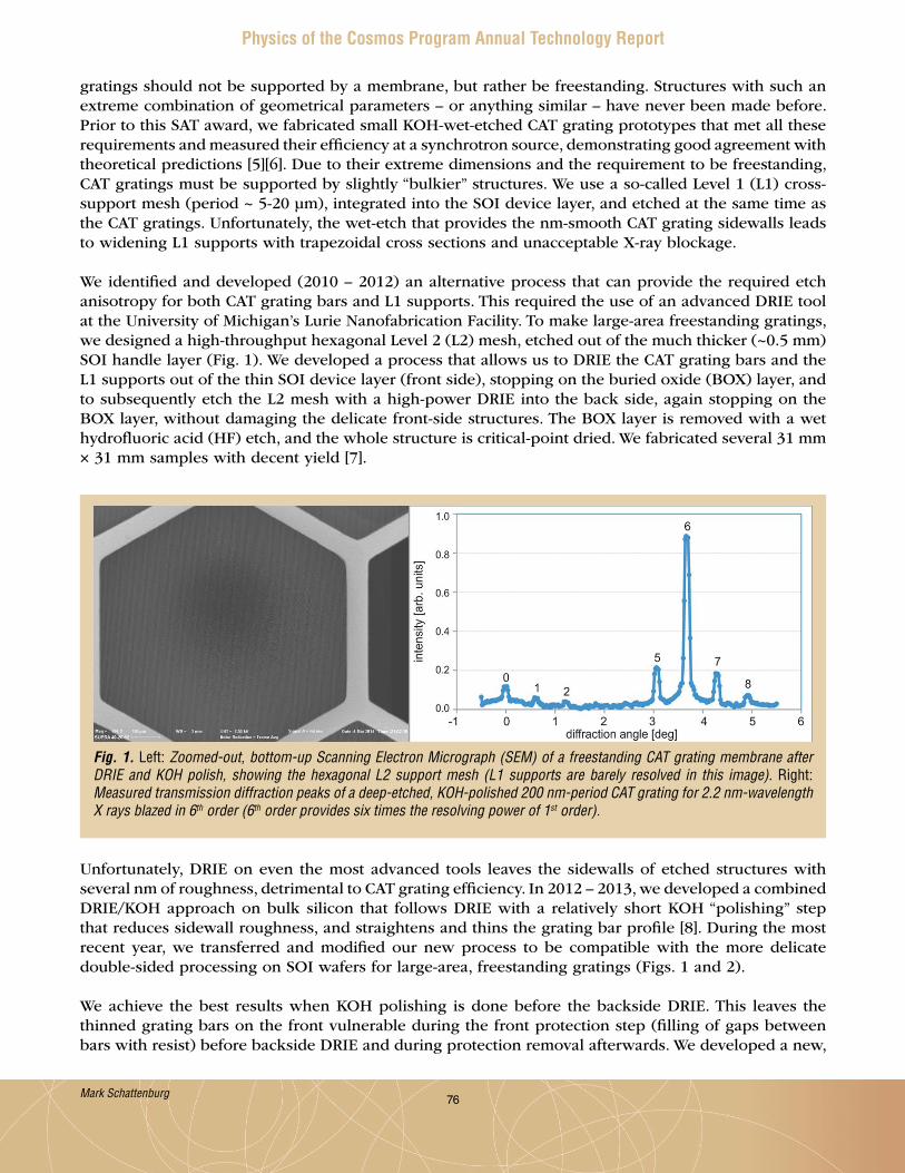
76
Physics of the Cosmos Program Annual Technology Report
gratings should not be supported by a membrane, but rather be freestanding . Structures with such an extreme combination of geometrical parameters – or anything similar – have never been made before . Prior to this SAT award, we fabricated small KOH-wet-etched CAT grating prototypes that met all these requirements and measured their efficiency at a synchrotron source, demonstrating good agreement with theoretical predictions [5][6] . Due to their extreme dimensions and the requirement to be freestanding, CAT gratings must be supported by slightly “bulkier” structures . We use a so-called Level 1 (L1) cross-support mesh (period ~ 5-20 µm), integrated into the SOI device layer, and etched at the same time as the CAT gratings . Unfortunately, the wet-etch that provides the nm-smooth CAT grating sidewalls leads to widening L1 supports with trapezoidal cross sections and unacceptable X-ray blockage .
We identified and developed (2010 – 2012) an alternative process that can provide the required etch anisotropy for both CAT grating bars and L1 supports . This required the use of an advanced DRIE tool at the University of Michigan’s Lurie Nanofabrication Facility . To make large-area freestanding gratings, we designed a high-throughput hexagonal Level 2 (L2) mesh, etched out of the much thicker (~0 .5 mm) SOI handle layer (Fig . 1) . We developed a process that allows us to DRIE the CAT grating bars and the L1 supports out of the thin SOI device layer (front side), stopping on the buried oxide (BOX) layer, and to subsequently etch the L2 mesh with a high-power DRIE into the back side, again stopping on the BOX layer, without damaging the delicate front-side structures . The BOX layer is removed with a wet hydrofluoric acid (HF) etch, and the whole structure is critical-point dried . We fabricated several 31 mm × 31 mm samples with decent yield [7] .
Fig. 1. Left: Zoomed-out, bottom-up Scanning Electron Micrograph (SEM) of a freestanding CAT grating membrane after DRIE and KOH polish, showing the hexagonal L2 support mesh (L1 supports are barely resolved in this image). Right: Measured transmission diffraction peaks of a deep-etched, KOH-polished 200 nm-period CAT grating for 2.2 nm-wavelength X rays blazed in 6th order (6th order provides six times the resolving power of 1st order).
Unfortunately, DRIE on even the most advanced tools leaves the sidewalls of etched structures with several nm of roughness, detrimental to CAT grating efficiency . In 2012 – 2013, we developed a combined DRIE/KOH approach on bulk silicon that follows DRIE with a relatively short KOH “polishing” step that reduces sidewall roughness, and straightens and thins the grating bar profile [8] . During the most recent year, we transferred and modified our new process to be compatible with the more delicate double-sided processing on SOI wafers for large-area, freestanding gratings (Figs . 1 and 2) .
We achieve the best results when KOH polishing is done before the backside DRIE . This leaves the thinned grating bars on the front vulnerable during the front protection step (filling of gaps between bars with resist) before backside DRIE and during protection removal afterwards . We developed a new,
Mark Schattenburg
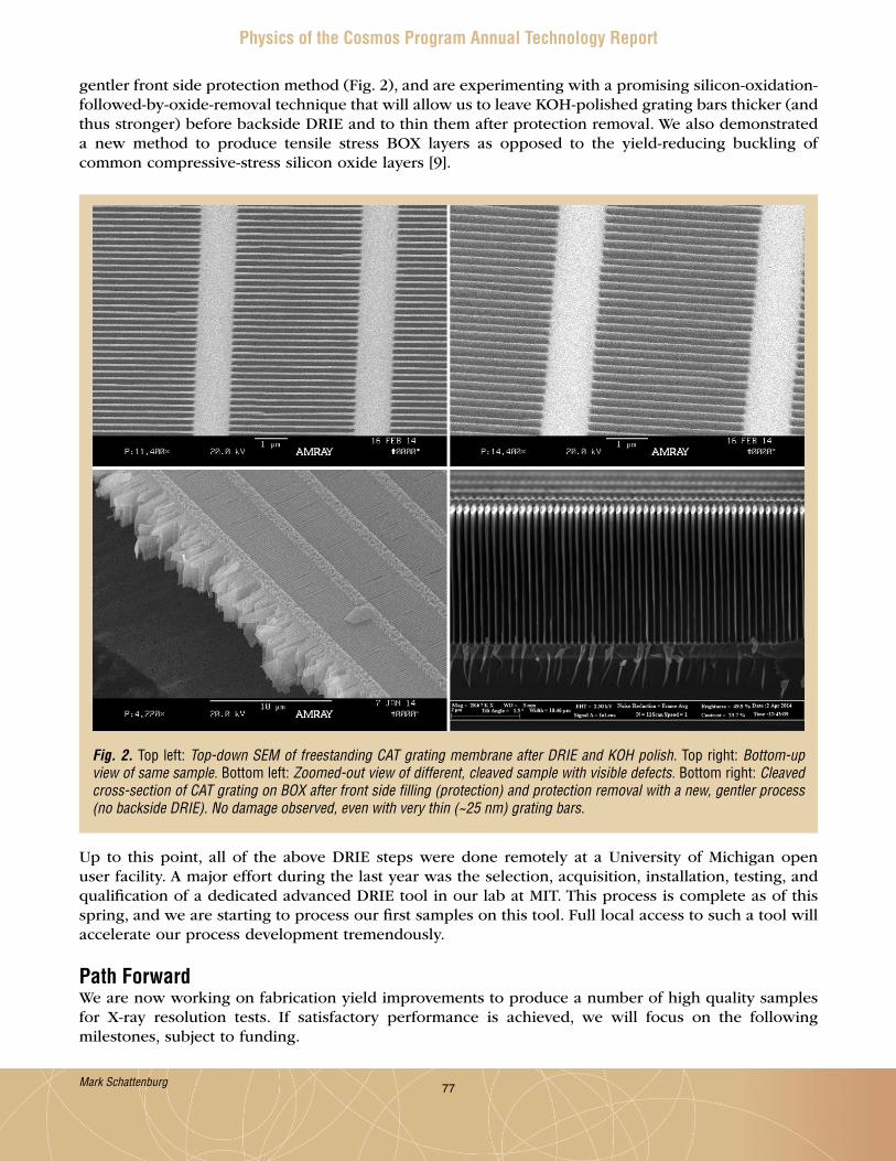
77
Physics of the Cosmos Program Annual Technology Report
gentler front side protection method (Fig . 2), and are experimenting with a promising silicon-oxidation-followed-by-oxide-removal technique that will allow us to leave KOH-polished grating bars thicker (and thus stronger) before backside DRIE and to thin them after protection removal . We also demonstrated a new method to produce tensile stress BOX layers as opposed to the yield-reducing buckling of common compressive-stress silicon oxide layers [9] .
Up to this point, all of the above DRIE steps were done remotely at a University of Michigan open user facility . A major effort during the last year was the selection, acquisition, installation, testing, and qualification of a dedicated advanced DRIE tool in our lab at MIT . This process is complete as of this spring, and we are starting to process our first samples on this tool . Full local access to such a tool will accelerate our process development tremendously .
Path ForwardWe are now working on fabrication yield improvements to produce a number of high quality samples for X-ray resolution tests . If satisfactory performance is achieved, we will focus on the following milestones, subject to funding .
Fig. 2. Top left: Top-down SEM of freestanding CAT grating membrane after DRIE and KOH polish. Top right: Bottom-up view of same sample. Bottom left: Zoomed-out view of different, cleaved sample with visible defects. Bottom right: Cleaved cross-section of CAT grating on BOX after front side filling (protection) and protection removal with a new, gentler process (no backside DRIE). No damage observed, even with very thin (~25 nm) grating bars.
Mark Schattenburg

78
Physics of the Cosmos Program Annual Technology Report
1 . Design of brass board GAS, alignment verification, and environmental test of grating array (FY 2015/16) .
2 . Scale up grating fabrication, frame design, and membrane/frame integration to full size (mission dependent – FY 2015/17) .
3 . Design and build GAS prototype (FY 2017) .4 . Environmental and X-ray tests of GAS populated with full-size gratings (FY 2017/18) .
References[1] R . K . Heilmann, J . E . Davis, D . Dewey, M . W . Bautz, R . Foster, A . Bruccoleri, P . Mukherjee, D . Robinson,
D . P . Huenemoerder, H . L . Marshall, M . L . Schattenburg, N . S . Schulz, L . J . Guo, A . F . Kaplan, and R . B . Schweickart, “Critical-Angle Transmission Grating Spectrometer for High-Resolution Soft X-Ray Spectroscopy on the International X-Ray Observatory,” Space Telescopes and Instrumentation 2010: Ultraviolet to Gamma Ray, M . Arnaud, S . S . Murray, T . Takahashi (eds .), Proc . SPIE 7732, 77321J (2010) .
[2] Jay A . Bookbinder, Randall K . Smith, Simon Bandler, Michael Garcia, Ann Hornschemeier, Robert Petre, and Andrew Ptak, “The Advanced X-ray Spectroscopic Imaging Observatory (AXSIO),” Proc . SPIE 8443, Space Telescopes and Instrumentation 2012: Ultraviolet to Gamma Ray, 844317 (2012) .
[3] M . W . Bautz, W . C . Cash, J . E . Davis, R . K . Heilmann, D . P . Huenemoerder, M . L . Schattenburg, R . McEntaffer, R . Smith, S . J . Wolk, W . W . Zhang, S . P . Jordan, and C . F . Lillie, “Concepts for High-Performance Soft X-Ray Grating Spectroscopy in a Moderate-Scale Mission,” Space Telescopes and Instrumentation 2012: Ultraviolet to Gamma Ray, T . Takahashi, S . S . Murray, and J .-W . A . den Herder (eds .), Proc . SPIE 8443, 844315 (2012) .
[4] A . Vikhlinin, P . Reid, H . Tananbaum, D . A . Schwartz, W . R . Forman, C . Jones, J . Bookbinder, V . Cotroneo, S . Trolier-McKinstry, D . Burrows, M . W . Bautz, R .K . Heilmann, J . Davis, S . R . Bandler, M . C . Weisskopf, and S . S . Murray, “SMART-X: Square Meter Arcsecond Resolution X-Ray Telescope,” Space Telescopes and Instrumentation 2012: Ultraviolet to Gamma Ray, T . Takahashi, S . S . Murray, and J .-W . A . den Herder (eds .), Proc . SPIE 8443, 844316 (2012) .
[5] R . K . Heilmann, M . Ahn, E . M . Gullikson, and M . L . Schattenburg, “Blazed High-Efficiency X-Ray Diffraction via Transmission through Arrays of Nanometer-Scale Mirrors,” Opt . Express 16, 8658 (2008) .
[6] R . K . Heilmann, M . Ahn, A . Bruccoleri, C .-H . Chang, E . M . Gullikson, P . Mukherjee, and M . L . Schattenburg, “Diffraction Efficiency of 200 nm Period Critical-Angle Transmission Gratings in the Soft X-Ray and Extreme Ultraviolet Wavelength Bands,” Appl . Opt . 50, 1364-1373 (2011) .
[7] A . Bruccoleri, P . Mukherjee, R . K . Heilmann, J . Yam, M . L . Schattenburg, and F . DiPiazza, “Fabrication of Nanoscale, High Throughput, High Aspect Ratio Freestanding Gratings,” J . Vac . Sci . Technol . B 30, 06FF03 (2012) .
[8] A . R . Bruccoleri, D . Guan, P . Mukherjee, R . K . Heilmann, and M . L . Schattenburg, “Potassium Hydroxide Polishing of Nanoscale Deep Reactive-Ion Etched Ultrahigh Aspect Ratio Gratings,” J . Vac . Sci . Technol . B 31, 06FF02 (2013) .
[9] D . Guan, A . R . Bruccoleri, R . K . Heilmann, and M . L . Schattenburg, “Stress Control of Plasma Enhanced Chemical Vapor Deposited Silicon Oxide Film from Tetraethoxysilane,” J . Micromech . Microeng . 24, 027001 (2014) .
For additional information, contact Mark Schattenburg: [email protected]
Mark Schattenburg

79
Physics of the Cosmos Program Annual Technology Report
Demonstrating Enabling Technologies for the High-Resolution Imaging Spectrometer of the Next NASA X-ray Astronomy MissionPrepared by: Caroline Kilbourne (PI; NASA/GSFC), Joel Ullom (NIST/Boulder), Kent Irwin (Stanford), Simon Bandler (NASA/GSFC)
SummaryWe are developing large-format arrays of X-ray microcalorimeters and their readout that will enable the next generation of high-resolution X-ray imaging spectrometers for astrophysics . These have very high spectral resolution, quantum efficiency, focal-plane coverage, and count-rate capability, combined with the ability to observe extended sources without spectral degradation . The goal of this program is to advance key components of an X-ray microcalorimeter imaging spectrometer from Technology Readiness Level (TRL) 4 to 5, and to advance a number of important related technologies to at least TRL 4 . This work is a collaboration between NASA/GSFC (PI C . Kilbourne); National Institute of Standards and Technology (NIST), Boulder (lead J . Ullom); and Stanford (lead K . Irwin); supported by the Strategic Astrophysics Technology (SAT) program . It began in Fiscal Year (FY) 2013, and is supported though FY 2015 . The scientists in our groups have been collaborating on technology development for an imaging X-ray microcalorimeter spectrometer – Transition Edge Sensor (TES) microcalorimeter arrays and time-division multiplexed Superconducting Quantum Interference Device (SQUID) readout – since 1998 . This collaboration previously brought the detector system to TRL 4 .
The landscape for future missions that will exploit the successes of this research program has recently changed, with the recent choice of the Advanced Telescope for High ENergy Astrophysics (ATHENA) [1] for the European L2 large mission slot . One of the two key instruments for this mission is called the X-ray Integral Field Unit (X-IFU) . X-IFU is based on the use of a large array of X-ray microcalorimeters as a high-resolution imaging spectrometer . The use of TES for the X-ray microcalorimeters, originally pioneered by our collaboration and under development under our SAT program, is currently assumed for this instrument [2] . With this choice, the possibilities for a near-term US-lead or joint-lead mission such as the International X-ray Observatory (IXO) [3] have now ended . Thus, the aim of our program has shifted toward our collaboration trying to make a significant contribution to ATHENA’s X-IFU . In addition to this possibility, there is a strong likelihood that our TES technology could contribute to one of the missions expected to be developed in Japan toward the end of this decade . Diffuse Intergalactic Oxygen Surveyor (DIOS) is under consideration as one of the next Japanese medium-scale satellite missions to launch near the end of this decade . In addition, a large-scale Japanese X-ray mission will be formulated following the launch of Astro-H, which could include one of our TES microcalorimeter array systems .
The primary goal of the current project is to advance the core detector-system technologies to a strong demonstration of TRL 5, to be suitably ready to respond to upcoming international opportunities . The details of what represents that TRL will depend on specific mission requirements . However, as a general representative set of TRL 5 requirements, we are aiming to demonstrate multiplexed (3 columns × 32 rows) readout of 96 different flight-like pixels . The pixels are intended to have a 0 .25 mm pitch in a 32 × 32 (or greater) array, with more than 95% of pixels achieving better than 3 eV resolution at 6 keV, using an analysis method consistent with the requirement of 80% live-time at an X-ray rate of 50/s/pixel . Vibration testing of an array is required to validate the pixels’ mechanical
Caroline Kilbourne

80
Physics of the Cosmos Program Annual Technology Report
design . Radiation testing of the detectors and readout is necessary to validate robustness in the space environment . Additional objectives of this program are to develop and demonstrate two important related technologies to at least TRL 4 – position-sensitive TES devices and code division multiplexing (CDM) . These technologies have the potential to expand significantly the range of possible instrument optimizations; together they allow an expanded focal plane and higher per-pixel count rates without greatly increasing mission resource requirements . The project also includes development of a design concept and critical technologies needed for the thermal, electrical, and mechanical integration of the detector and readout components into the focal-plane assembly .
BackgroundThe ability to perform broadband imaging X-ray spectroscopy with high spectral and spatial resolution was an essential capability of the IXO mission concept . Despite the fourth-place ranking of IXO in the 2010 NRC decadal review of astrophysics, New Worlds, New Horizons (NWNH), the IXO science focus was strongly endorsed in the review, as was investing in its key technologies . Quoting the NWNH, “Because of IXO’s high scientific importance, a technology development program is recommended this decade with sufficient resources.” The technology development program we are pursuing is a response to this endorsement, now redirected towards the future missions ATHENA and a nearer-term Japanese X-ray astrophysics mission . The science case for developing microcalorimeter technology is that of the universe of extremes, from black holes to large-scale structure . The main goals are structured around three main topics – “black holes and accretion physics,” “cosmic feedback,” and “large-scale structure of the universe” . Underpinning these topics is the study of hot astrophysical plasmas that broadens the scope of this science to virtually all corners of astronomy .
The reference technology for these missions consists of Mo/Au TES thermometers (operated at < 0 .1 K) with close-packed Bi/Au thermalizing X-ray absorbers on a 0 .25-0 .3 mm pitch . In the baseline time-division multiplexing (TDM) concept [4], outputs from the dedicated input SQUIDs of individual TES pixels are coupled to a single amplifier, and multiplexing is achieved by sequential switching of these input SQUIDs . Energy resolution of better than 3 eV full-width at half maximum (FWHM) at 6 keV is required, with a high-resolution live-time of no less than 80% at a count rate of 50 events/s/pixel, and a bandpass of 0 .1-12 keV .
The integrated detector system reached TRL 4 in March 2008 with the successful demonstration [5] of multiplexed (2 columns × 8 rows) readout of 16 different pixels (in an 8 × 8 array) similar to those in the current reference design . Reaching this milestone showed the baseline technology approach is fundamentally sound . The detector pixels were sufficiently uniform to permit good performance under common bias, and the modest degradation of detector performance while multiplexed was consistent with models . Resolution across 16 multiplexed pixels ranged from 2 .6 eV to 3 .1 eV, and the pulse time constant was 0 .28 ms . This “2 × 8 demo” achieved the most fundamental goal of a demonstration of TRL 4 (as articulated in NPR 7120 .8 – NASA Research and Technology Program and Project Management Requirements and expanded in [6]) – basic technological components were integrated to establish that they will work together . The performance approached the requirements of potential system applications in terms of resolution, speed, pixel scale, and quantum efficiency .
Progress and AccomplishmentsMultiplexed Readout of Large-Format ArraysOver the past year, we successfully developed an array of pixels demonstrating excellent spectroscopic performance (Fig . 1) . The array is a 32 × 32 array of pixels on a 250 µm pitch . All pixels are wired out to the edge of the array, but only 256 of the pixels (25%) have wiring going to bond pads around the circumference of the silicon carrier wafer .
Caroline Kilbourne

81
Physics of the Cosmos Program Annual Technology Report
Fig. 1. A 32 × 32 array of close-packed X-ray microcalorimeters. Only the X-ray absorbers are visible, consisting of a 1.5 µm thick layer of gold and a 3.0 µm thick layer of bismuth. The absorbers are 242 µm × 242 µm in size, on a 250 µm pitch. Inset is a scanning electron microscope image of four pixels within the array. The absorbers are cantilevered above TES sensors, with the wiring in-between pixels. The inverted ‘T’ image imprinted on each absorber is the region where the absorbers are supported by the substrate, making contact to the TES.
The pixels’ X-ray spectroscopy performance is excellent . A FWHM energy resolution of 1 .8 eV was achieved at 6 keV when reading out just one pixel of this type . Thus, the array is highly suitable for demonstrating the achievable multiplexed performance using TDM [4] . TDM is a sequential and cyclical readout of ‘N’ rows of SQUIDs, each of which is attached to a separate TES pixel . The faster we can “switch” the readout from one pixel to the next, the more pixels we can read out with each room-temperature amplifier . Figure 2 shows our latest results from the multiplexed readout of our kilo-pixel array . It shows the spectroscopic capability when reading out two amplifier signals (columns) from the array, each of which multiplexes the readout of 16 pixels . Note that although all 16 rows were sampled in sequence, one row/pixel in each column did not produce results due to a non-functioning SQUID .
The energy resolution is mostly just under 3 eV at 6 keV in the first column, approaching the goal of 2 .5 eV . For this measurement there is some small energy resolution degradation due to non-uniformity of the SQUIDs being used, particularly in the second column . Other sources of minor energy resolution degradation include the effects of multiplexed cross-talk and arrival time variation on the time-scale of the multiplexing that has not been entirely corrected for in this dataset . The rate of switching readout between consecutive pixels was 3 MHz, or 340 ns between pixel-switching . It was also shown that the readout was stable and gave a similar energy resolution when multiplexing each pixel as if there
Caroline Kilbourne
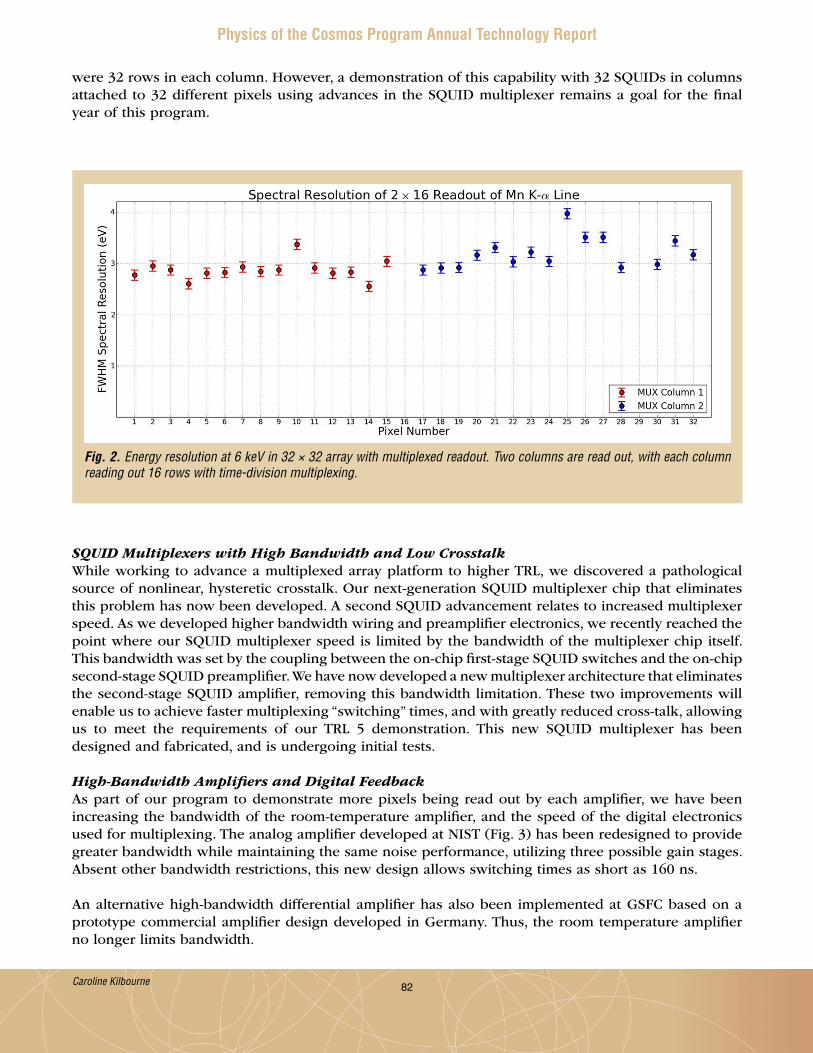
82
Physics of the Cosmos Program Annual Technology Report
SQUID Multiplexers with High Bandwidth and Low CrosstalkWhile working to advance a multiplexed array platform to higher TRL, we discovered a pathological source of nonlinear, hysteretic crosstalk . Our next-generation SQUID multiplexer chip that eliminates this problem has now been developed . A second SQUID advancement relates to increased multiplexer speed . As we developed higher bandwidth wiring and preamplifier electronics, we recently reached the point where our SQUID multiplexer speed is limited by the bandwidth of the multiplexer chip itself . This bandwidth was set by the coupling between the on-chip first-stage SQUID switches and the on-chip second-stage SQUID preamplifier . We have now developed a new multiplexer architecture that eliminates the second-stage SQUID amplifier, removing this bandwidth limitation . These two improvements will enable us to achieve faster multiplexing “switching” times, and with greatly reduced cross-talk, allowing us to meet the requirements of our TRL 5 demonstration . This new SQUID multiplexer has been designed and fabricated, and is undergoing initial tests .
High-Bandwidth Amplifiers and Digital FeedbackAs part of our program to demonstrate more pixels being read out by each amplifier, we have been increasing the bandwidth of the room-temperature amplifier, and the speed of the digital electronics used for multiplexing . The analog amplifier developed at NIST (Fig . 3) has been redesigned to provide greater bandwidth while maintaining the same noise performance, utilizing three possible gain stages . Absent other bandwidth restrictions, this new design allows switching times as short as 160 ns .
An alternative high-bandwidth differential amplifier has also been implemented at GSFC based on a prototype commercial amplifier design developed in Germany . Thus, the room temperature amplifier no longer limits bandwidth .
Fig. 2. Energy resolution at 6 keV in 32 × 32 array with multiplexed readout. Two columns are read out, with each column reading out 16 rows with time-division multiplexing.
were 32 rows in each column . However, a demonstration of this capability with 32 SQUIDs in columns attached to 32 different pixels using advances in the SQUID multiplexer remains a goal for the final year of this program .
Caroline Kilbourne
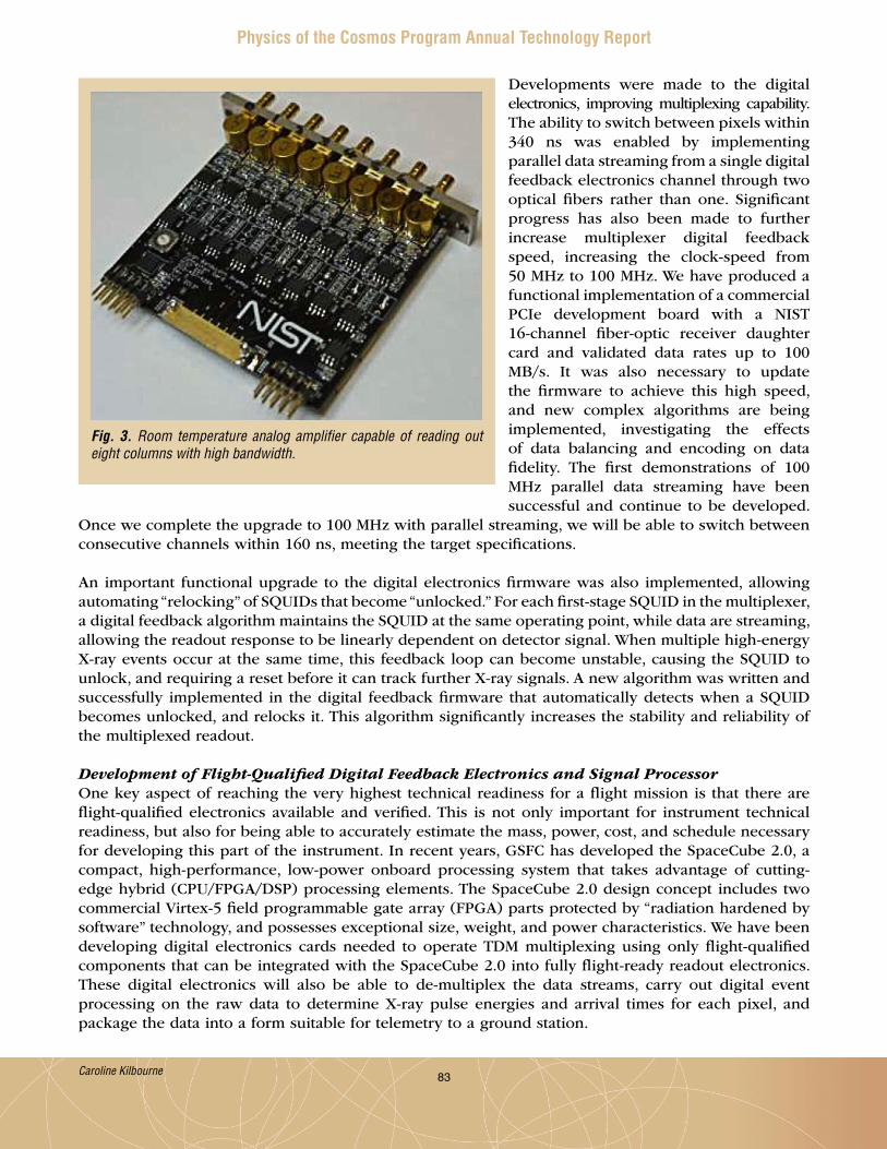
83
Physics of the Cosmos Program Annual Technology Report
Developments were made to the digital electronics, improving multiplexing capability . The ability to switch between pixels within 340 ns was enabled by implementing parallel data streaming from a single digital feedback electronics channel through two optical fibers rather than one . Significant progress has also been made to further increase multiplexer digital feedback speed, increasing the clock-speed from 50 MHz to 100 MHz . We have produced a functional implementation of a commercial PCIe development board with a NIST 16-channel fiber-optic receiver daughter card and validated data rates up to 100 MB/s . It was also necessary to update the firmware to achieve this high speed, and new complex algorithms are being implemented, investigating the effects of data balancing and encoding on data fidelity . The first demonstrations of 100 MHz parallel data streaming have been successful and continue to be developed .
Once we complete the upgrade to 100 MHz with parallel streaming, we will be able to switch between consecutive channels within 160 ns, meeting the target specifications .
An important functional upgrade to the digital electronics firmware was also implemented, allowing automating “relocking” of SQUIDs that become “unlocked .” For each first-stage SQUID in the multiplexer, a digital feedback algorithm maintains the SQUID at the same operating point, while data are streaming, allowing the readout response to be linearly dependent on detector signal . When multiple high-energy X-ray events occur at the same time, this feedback loop can become unstable, causing the SQUID to unlock, and requiring a reset before it can track further X-ray signals . A new algorithm was written and successfully implemented in the digital feedback firmware that automatically detects when a SQUID becomes unlocked, and relocks it . This algorithm significantly increases the stability and reliability of the multiplexed readout .
Development of Flight-Qualified Digital Feedback Electronics and Signal Processor One key aspect of reaching the very highest technical readiness for a flight mission is that there are flight-qualified electronics available and verified . This is not only important for instrument technical readiness, but also for being able to accurately estimate the mass, power, cost, and schedule necessary for developing this part of the instrument . In recent years, GSFC has developed the SpaceCube 2 .0, a compact, high-performance, low-power onboard processing system that takes advantage of cutting-edge hybrid (CPU/FPGA/DSP) processing elements . The SpaceCube 2 .0 design concept includes two commercial Virtex-5 field programmable gate array (FPGA) parts protected by “radiation hardened by software” technology, and possesses exceptional size, weight, and power characteristics . We have been developing digital electronics cards needed to operate TDM multiplexing using only flight-qualified components that can be integrated with the SpaceCube 2 .0 into fully flight-ready readout electronics . These digital electronics will also be able to de-multiplex the data streams, carry out digital event processing on the raw data to determine X-ray pulse energies and arrival times for each pixel, and package the data into a form suitable for telemetry to a ground station .
Fig. 3. Room temperature analog amplifier capable of reading out eight columns with high bandwidth.
Caroline Kilbourne

84
Physics of the Cosmos Program Annual Technology Report
Path ForwardRecent emphasis has been on developments toward reaching TRL 5, and achieving a 3 × 32 multiplexed readout demonstration of a portion of our kilo-pixel arrays . We have been improving readout components, system bandwidth, and detector arrays . Once this TRL 5 demonstration has been achieved, we will proceed to demonstrate multiplexed readout of other microcalorimeter pixel types .
We have been developing arrays of small pixels [7] and TESs attached to multiple absorbers [8] as part of our broader program to develop a wide variety of microcalorimeter array options for future X-ray missions . Our program to increase microcalorimeter array TRL also includes development of multiplexed readout for these types of pixels . Small arrays of pixels optimized for point sources, with either high count-rate capability and high dynamic range, or higher energy resolution at reduced dynamic range, are very attractive array design options . The virtues of having an array of small pixels that over-sample the point spread function of the optic, and have high dynamic range and high count-rate capability has been described by Ptak, et al. [9] . Improved energy resolution for soft X rays is similarly attractive . Spectroscopic studies with a resolution of 1 eV rather than 2 .5 eV would make it possible, for example, to resolve many more lines when studying star formation . Figure 4 shows a scanning electron microscope image of a recently developed 12 × 12 array of pixels on a 50 µm pitch, and the sub-eV energy resolution achievable at low energies with this type of pixel .
Array designs with more pixels than TESs allow for larger focal plane coverage without a commensurate increase in the number of wires or readout components . In the “Hydra” geometry, a single TES is coupled to multiple different discrete absorbers . Each absorber element has a different thermal conductance to the sensor, which results in position information being encoded in the pre-equilibration pulse shape . The energy of the photon can then be calculated using a single stored digital optimal filter for each pixel . The associated increase in the complexity of the analysis electronics, from the added task of determining the event location, is minimal [8] . We have been developing Hydras with absorber sizes ranging from 50 µm to 600 µm, and number of absorbers attached to each TES ranging from 4 to 24 . We have achieved a wide variety of results for the various Hydra design options . Perhaps the most relevant geometry for future astrophysics missions is one in which four 250 µm absorbers are attached to each TES . The energy resolution expected for this type of geometry is better than 4 eV . We are currently developing Hydras of this type, and integrating them within the same focal plane as our standard single pixels in a hybrid array format . We are also integrating small pixels with these other array types in an attempt to provide the widest possible variety of array options for future X-ray astrophysics missions . We are beginning to investigate the readout requirements of these broader pixel types, and over the next year will incorporate the multiplexed testing of these pixels into our research program to improve their TRL in preparation for a potential contribution to ATHENA and to a Japanese mission in the latter part of this decade .
Caroline Kilbourne
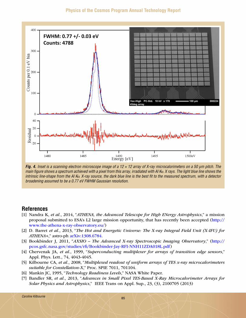
85
Physics of the Cosmos Program Annual Technology Report
References[1] Nandra K, et al., 2014, “ATHENA, the Advanced Telescope for High ENergy Astrophysics,” a mission
proposal submitted to ESA’s L2 large mission opportunity, that has recently been accepted (http://www .the-athena-x-ray-observatory .eu/)
[2] D . Barret et al., 2013, “The Hot and Energetic Universe: The X-ray Integral Field Unit (X-IFU) for ATHENA+,” astro-ph arXiv:1308 .6784 .
[3] Bookbinder J, 2011, “AXSIO – The Advanced X-ray Spectroscopic Imaging Observatory,” (http://pcos .gsfc .nasa .gov/studies/rfi/Bookbinder-Jay-RFI-NNH11ZDA018L .pdf)
[4] Chervenak JA, et al., 1999, “Superconducting multiplexer for arrays of transition edge sensors,” Appl . Phys . Lett ., 74, 4043-4045 .
[5] Kilbourne CA, et al., 2008, “Multiplexed readout of uniform arrays of TES x-ray microcalorimeters suitable for Constellation-X,” Proc . SPIE 7011, 701104 .
[6] Mankin JC, 1995, “Technology Readiness Levels,” NASA White Paper .[7] Bandler SR, et al., 2013, “Advances in Small Pixel TES-Based X-Ray Microcalorimeter Arrays for
Solar Physics and Astrophysics,” IEEE Trans on Appl . Sup ., 23, (3), 2100705 (2013)
Fig. 4. Inset is a scanning electron microscope image of a 12 × 12 array of X-ray microcalorimeters on a 50 µm pitch. The main figure shows a spectrum achieved with a pixel from this array, irradiated with Al Kα X rays. The light blue line shows the intrinsic line-shape from the Al Kα X-ray source, the dark blue line is the best fit to the measured spectrum, with a detector broadening assumed to be a 0.77 eV FWHM Gaussian resolution.
Caroline Kilbourne

86
Physics of the Cosmos Program Annual Technology Report
[8] Smith, SJ, et al., 2009, “Development of position-sensitive transition-edge sensor X-ray detectors,” IEEE Trans . Appl . Superconductivity, 19, 451 .
[9] Ptak A, et al., 2013, “Designing the X-ray Microcalorimeter Spectrometer for Optimal Science Return,” Proc . SPIE 8859, UV, X-Ray, and Gamma-Ray Space Instrumentation for Astronomy XVIII, 885903 .
For additional information, contact Caroline Kilbourne: [email protected]
Caroline Kilbourne

87
Physics of the Cosmos Program Annual Technology Report
Next-Generation X-ray Optics: High Angular Resolution, High Throughput, and Low CostPrepared by: William W. Zhang (PI; NASA/GSFC) and Stephen L. O’Dell (NASA/MSFC)
SummaryThis work continues technology development of X-ray optics for high-energy astrophysics . Since Fiscal Year (FY) 2012, the Strategic Astrophysics Technology (SAT) program has funded this effort, which the Constellation-X project initiated and the International X-ray Observatory (IXO) project continued . Led by the NASA Goddard Space Flight Center (GSFC), in collaboration with the NASA Marshall Space Flight Center (MSFC), and the Smithsonian Astrophysical Observatory (SAO), we believe this technology development has achieved TRL 5 for building 10 arcsec X-ray mirror assemblies as of May 2014, and is on track to achieve TRL 5 for building 5 arcsec X-ray mirror assemblies by December 2016 .
The objective is to advance astronomical X-ray optics by at least an order of magnitude in one or more of three key metrics from the state-of-the-art represented by the four major X-ray missions currently in operation: Chandra, X-ray Multi-mirror Mission-Newton (XMM-Newton), Suzaku, and Nuclear Spectroscopic Telescope Array (NuSTAR) . These metrics are (1) angular resolution, (2) mass per unit area, and (3) production cost per unit area . The modular nature of this technology renders it appropriate for missions of all sizes—from Explorers and Probes that can be implemented by the end of this decade, to flagship missions that can be implemented during the next decade .
Key areas of technology development include (1) fabrication of substrates, (2) thin-film coating of these substrates to make X-ray mirror segments, (3) alignment and (4) bonding of mirror segments into mirror modules, and (5) systems engineering to ensure all spaceflight requirements are met . During the past year, we made progress in each of these areas, culminating in the fabrication of technology development modules (TDMs) that passed a battery of environmental tests, and produced X-ray images with a half-power diameter (HPD) of 8 arcsec . This represents a significant advance over the 11 arcsec images we reported at the end of FY 2013 and the 17 arcsec reported at the end of FY 2012 . We expect to improve image quality further, to better than 5 arcsec over the next two years, and to better than 1 arcsec by the end of this decade .
BackgroundThe last five centuries of astronomy are a history of technological advancements in optical fabrication and optical-systems integration . Furthering our understanding of the cosmos requires telescopes with ever more collecting area and finer angular resolution . In the visible and other wavelength bands, where radiation can be reflected at normal incidence, a large mirror area directly translates into a large photon-collecting area . However, due to its grazing-incidence nature, an X-ray telescope requires a combination of large area and thin mirrors to increase photon-collecting area .
Three metrics capture the essence of an X-ray optics technology: (1) angular resolution, (2) mass per unit collecting area, and (3) production cost per unit collecting area . Table 1 compares these metrics for this technology with Chandra, XMM-Newton, Suzaku, and NuSTAR . The X-ray optics of each of these observatories represents a scientifically powerful compromise between these three metrics that was implementable in its specific technological, budgetary, schedule, and spaceflight opportunity context .
William Zhang

88
Physics of the Cosmos Program Annual Technology Report
Compared with Chandra, this technology would lower mass and cost per unit collecting area by nearly two orders of magnitude . Compared to XMM-Newton, it would reduce mass per unit collecting area by a factor of 8 and cost by a factor of 3, while significantly improving angular resolution . In comparison with Suzaku and NuSTAR, it would improve angular resolution by an order of magnitude, while preserving their advantages in mass and cost per unit collecting area .
A salient feature of this technology is that it utilizes a segmented design, as did Suzaku and NuSTAR . Such a design brings modularity and scalability, minimizing production cost and enabling missions of any size—from small Explorer missions to large flagship missions . Small and large mirror assemblies differ only in the number of identical mirror modules that need to be constructed, aligned, and integrated . Each of these modules would typically measure 200 mm × 200 mm × 400 mm (optical axial direction), with a mass of about 10 kg, rendering them easy to handle . Construction of many identical modules lends itself to mass production, offering substantial cost and schedule savings .
Objectives and MilestonesIn the near term (2 years or so), we expect to demonstrate an entire process for making mirror modules that produce X-ray images better than 5 arcsec HPD in a consistent and repeatable manner, and that can pass all environmental tests required for spaceflight . In the long term (next 5–10 years), we expect to continually improve every aspect of the process toward better angular resolution from 5 arcsec to less than 1 arcsec, with the ultimate goal of achieving diffraction-limited X-ray optics in the 2020s .
The same set of milestones can be used to measure progress toward realizing both near-term and long-term objectives . They differ only in the X-ray image quality measured in arcsec . Each step or milestone has two metrics: image quality and consistency .
1 . Fabrication of mirror substrates;2 . Maximizing X-ray reflectivity by coating substrates with thin-film iridium or other material;3 . Alignment of individual mirror segments and pairs of mirror segments;4 . Bonding of mirror segments;
Mission Launch Year
Mirror Technology Angular Resolution
HPD (arcsec)
Mass per Unit Collecting Area @
1 keV (kg/m2)
Production Cost per Unit Collecting Area @
1 keV (2013 $M/m2)Chandra 1999 Ground and polished
Zerodur™ shells0.5 18,000 ~9,800
XMM-Newton 1999 Electroformed nickel shells 15 3,200 ~360Suzaku 2005 Epoxy-replicated aluminum
segments120 400 ~88
NuSTAR 2012 Slumped-glass segments 58 400 ~80NGXO Current Status
NA Slumped-glass segments 8 ~400 ~80
Near-Term (2 y) Objective
NA Polished and light-weighted single-crystal silicon segments
5 ~400 ~80
Long-Term (5-10 y) Objective
NA <1 ~400 ~80
Table 1. Comparison of the objectives of this technology effort with the state-of-the-art as represented by the four major X-ray missions currently in operation. Given the difficulty in ascertaining cost of a specific mission component, the costs quoted here are estimates.
William Zhang

89
Physics of the Cosmos Program Annual Technology Report
5 . Construction of mirror modules, requiring co-alignment and bonding of multiple mirror segments; and6 . Environmental tests of mirror modules, with mirror module X-ray performance tests before and
after environmental tests .
Environmental tests include vibration, acoustic, and thermal-vacuum . X-ray performance tests include measurement of point spread function and effective area at representative X-ray energies – e.g., 1 .5 keV (aluminum Kα), 4 .5 keV (titanium Kα), and 8 .0 keV (copper Kα) .
Progress and AccomplishmentsIn the past year, we made progress in every area of the technology: substrate fabrication; coating; mirror alignment; mirror bonding; and module design, analysis, construction, and testing .
Substrate FabricationAlthough not an emphasis of our FY 2014 work, we continued refining and simplifying the glass-slumping process . We brought the recently finished forming-mandrel pairs (356P/S and 368P/S) to producing substrates suitable for fabricating 6 arcsec mirror assemblies . Overall, we maintained substrate fabrication consistency, resulting in a predicted imaging performance of 6 arcsec HPD (two reflections) .
Meanwhile, in a concurrent effort funded by the Astrophysics Research and Analysis (APRA) program under the Research Opportunities in Space and Earth Sciences (ROSES), we advanced the technology of making lightweight, single-crystal-silicon mirror substrates . We demonstrated that both flat and curved (cylinder-like) substrates can be made that meet both thickness (less than 0 .5 mm) and lightweight (areal density less than 1 kg/m2) requirements . We are in the process of improving their figure and expect to produce substrates surpassing the 6 arcsec HPD of slumped-glass substrates sometime in FY 2015, transitioning this development program from using glass substrates to single-crystal silicon ones .
CoatingA mirror substrate requires an optical coating (e.g., 20-nm iridium) to enhance its X-ray reflectivity . The stress of an iridium film, typically several Giga-Pascal, severely distorts the figure of a thin substrate, greatly degrading its imaging quality . In FY 2014, we continued our investigation of two methods for dealing with coating stress: (1) cancellation by coating both front (concave) and back (convex) surfaces of the substrate, and (2) thermal annealing to relieve film stress . For two-sided coating, we conclude that coating stress does not cancel with sufficient precision to result in acceptable figure distortion . Potential causes of incomplete cancellation are insufficient thickness uniformity and non-repeatable coating conditions . For atomic layer deposition, thickness non-uniformity may have resulted from non-uniform subsurface molecular contamination that may retard or accelerate nucleation . We found that a carefully executed thermal annealing process provides the best way of reducing coating stress . During the past year, we optimized thermal annealing parameters, reducing coating stress sufficiently to enable coated mirror segments to meet requirements for a 5 arcsec mirror assembly .
Mirror Segment AlignmentThe alignment of each mirror segment entails closed-loop operation of a hexapod, a beam of laser light, and an optical CCD imager . The alignment step must meet two requirements . First, it must maneuver the mirror segment into its prescribed location and orientation to achieve the best possible image in conjunction with other mirror segments . Second, it must hold the mirror segment steady in the optimal configuration for a sufficient time for it to be permanently affixed to the module housing .
After installing and commissioning a precision temperature-control unit in FY 2013, the superb thermal stability of the laboratory allowed us to identify in FY 2014 hexapod hysteresis and drift as culprits
William Zhang
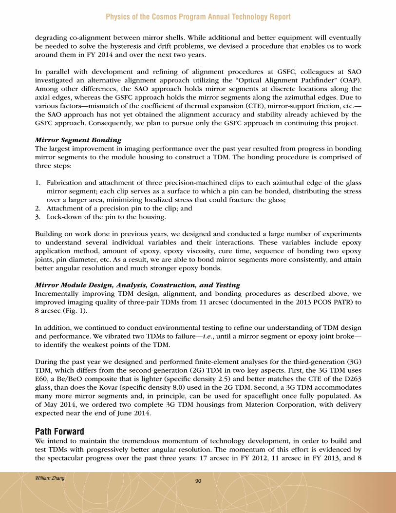
90
Physics of the Cosmos Program Annual Technology Report
degrading co-alignment between mirror shells . While additional and better equipment will eventually be needed to solve the hysteresis and drift problems, we devised a procedure that enables us to work around them in FY 2014 and over the next two years .
In parallel with development and refining of alignment procedures at GSFC, colleagues at SAO investigated an alternative alignment approach utilizing the “Optical Alignment Pathfinder” (OAP) . Among other differences, the SAO approach holds mirror segments at discrete locations along the axial edges, whereas the GSFC approach holds the mirror segments along the azimuthal edges . Due to various factors—mismatch of the coefficient of thermal expansion (CTE), mirror-support friction, etc .—the SAO approach has not yet obtained the alignment accuracy and stability already achieved by the GSFC approach . Consequently, we plan to pursue only the GSFC approach in continuing this project .
Mirror Segment BondingThe largest improvement in imaging performance over the past year resulted from progress in bonding mirror segments to the module housing to construct a TDM . The bonding procedure is comprised of three steps:
1 . Fabrication and attachment of three precision-machined clips to each azimuthal edge of the glass mirror segment; each clip serves as a surface to which a pin can be bonded, distributing the stress over a larger area, minimizing localized stress that could fracture the glass;
2 . Attachment of a precision pin to the clip; and3 . Lock-down of the pin to the housing .
Building on work done in previous years, we designed and conducted a large number of experiments to understand several individual variables and their interactions . These variables include epoxy application method, amount of epoxy, epoxy viscosity, cure time, sequence of bonding two epoxy joints, pin diameter, etc . As a result, we are able to bond mirror segments more consistently, and attain better angular resolution and much stronger epoxy bonds .
Mirror Module Design, Analysis, Construction, and TestingIncrementally improving TDM design, alignment, and bonding procedures as described above, we improved imaging quality of three-pair TDMs from 11 arcsec (documented in the 2013 PCOS PATR) to 8 arcsec (Fig . 1) .
In addition, we continued to conduct environmental testing to refine our understanding of TDM design and performance . We vibrated two TDMs to failure—i.e., until a mirror segment or epoxy joint broke—to identify the weakest points of the TDM .
During the past year we designed and performed finite-element analyses for the third-generation (3G) TDM, which differs from the second-generation (2G) TDM in two key aspects . First, the 3G TDM uses E60, a Be/BeO composite that is lighter (specific density 2 .5) and better matches the CTE of the D263 glass, than does the Kovar (specific density 8 .0) used in the 2G TDM . Second, a 3G TDM accommodates many more mirror segments and, in principle, can be used for spaceflight once fully populated . As of May 2014, we ordered two complete 3G TDM housings from Materion Corporation, with delivery expected near the end of June 2014 .
Path ForwardWe intend to maintain the tremendous momentum of technology development, in order to build and test TDMs with progressively better angular resolution . The momentum of this effort is evidenced by the spectacular progress over the past three years: 17 arcsec in FY 2012, 11 arcsec in FY 2013, and 8
William Zhang

91
Physics of the Cosmos Program Annual Technology Report
The 8 arcsec HPD of current TDMs has two major contributions – mirror substrates and gravity distortion during X-ray testing in a horizontal beam . As such, our path to 5 arcsec HPD images is as follows:
1 . Consolidate the current alignment and bonding process to achieve consistency; build more TDMs to be tested for both performance and environmental robustness; transition from 2G Kovar housing to 3G E60 housing, which can accommodate more than 3 pairs of mirror segments;
2 . Transition from slumped-glass to polished and lightweighted single-crystal-silicon substrates, achieving better than 4 arcsec HPD substrates, needed to achieve 5 arcsec HPD TDMs; and
3 . Complete modification of an existing 600 m X-ray beam line to enable a TDM to be tested with its optical axis in the vertical direction, reducing gravity-induced distortion by more than an order of magnitude .
We anticipate that successful completion of the above three tasks will lead to TDMs with better (possibly significantly better) than 5 arcsec HPD . At that point, we shall conduct a detailed error analysis to determine the remaining dominant contributors to image blur . These contributors, which likely include coating stress and distortion due to epoxy bonding, will become natural targets for our future work .
For additional information, contact William Zhang: [email protected]
Fig. 1. (a) A representative TDM containing three co-aligned and bonded primary–secondary (paraboloid–hyperboloid) mirror pairs, shown in an X-ray chamber for full-illumination testing; (b) TDM X-ray image at 4.5 keV, displayed in a logarithmic scale to clearly show image shape; (c) Details of background analysis of image (b); (d) Encircled energy vs. diameter, showing HPD of 8.3 arcsec and 90%-encircled-energy diameter of 33.2 arcsec.
ab
C
d
arcsec in FY 2014 . We expect to build TDMs with at least five pairs of mirror segments that can produce better than 5 arcsec HPD images by December 2016, readying this technology for a MIDEX mission opportunity that NASA HQ is expected to release in late 2016 or 2017, as well as for the European Space Agency (ESA) Advanced Telescope for High-Energy Astrophysics (ATHENA) mission .
William Zhang

92
Physics of the Cosmos Program Annual Technology Report
Adjustable X-ray Optics with Sub-Arcsec ImagingPrepared by: Paul B. Reid (PI; SAO) and Stuart McMuldroch (SAO)
SummaryAdjustable X-ray optics with sub-arcsec imaging is an Astronomy and Physics Research and Analysis (APRA) program that began in February 2013 and is scheduled to run through the end of Fiscal Year (FY) 2015 . This program follows an earlier APRA project to develop adjustable X-ray optics . This program seeks to develop bimorph adjustable grazing-incidence X-ray mirrors to achieve 0 .5 arcsec imaging while also achieving extremely light weight per unit collecting area (e.g., ~250 kg/m2 compared to Chandra’s ~20,000 kg/m2) . Our technology will enable large area, high resolution imaging X-ray telescope mission concepts such as the Square Meter Arc-second Resolution Telescope for X-rays (SMART-X) [1] . SMART-X will study the early universe (growth of structure, merger history of black holes), as well as feedback and evolution of matter and energy .
Our technology eliminates the figure errors and unwanted distortions usually inherent in thin light-weight mirrors . We use a thin (nominally 1 .5 µm) film of the piezoelectric material lead zirconate titanate (PZT), sputtered as a continuous film on the back of thin (0 .4 mm) thermally formed glass Wolter-I mirror segments (a continuous ground electrode is first applied to the back surface) . A pattern of independently addressable platinum (Pt) electrodes is deposited on top of the PZT layer, forming individual piezo-cells . Applying a low (< 10V) DC voltage between a cell’s top electrode and the ground electrode creates an electric field that produces a local strain in the piezo material parallel to the mirror surface . This strain causes localized bending in the mirror, called an influence function . By supplying an optimally chosen voltage to each of the individual cells, one can change the amplitude of each influence function to minimize figure errors in the mirror, thereby improving imaging performance . This allows us to correct mirror figure errors from fabrication, distortions introduced during mounting, and any gravity-release errors . Figure correction is made once on the ground during a calibration step after mirror alignment and mounting . Having the ability to adjust and correct the figure of thin mirror segments increases their performance from the 10 arcsec resolution level to 0 .5 arcsec . We have shown through simulations improvements from ~7 arcsec half power diameter (HPD) to < 0 .5 arcsec HPD using exemplar mirror figure data and modeled influence functions [2] .
Besides the adjustable optics and SMART-X teams at the Smithsonian Astrophysical Observatory (SAO), significant contributors to the adjustable optics team are our colleagues at The Penn State University (PSU) Materials Research Laboratory and the NASA Marshall Space Flight Center (MSFC) . Dr . Susan Trolier-McKinstry at PSU, supported by Dr . Rudeger (Derek) H .T . Wilke and Dr . Raegan Johnson-Wilke, develops the PZT processes . At MSFC, Dr . Mikhail (Mischa) Gubarev, Dr . Stephen O’Dell, and Dr . Brian Ramsey support metrology, analysis activities, and will lead X-ray testing .
This year important progress was made in several areas:
• Piezo-cell voltage optimization – a bounded, constrained, least squares optimizer using root mean square (rms) surface-slope error as a merit function was implemented;
• A mounting and alignment approach suitable for TRL 4 X-ray testing was modeled and designed (component parts are in fabrication);
• Metrology accuracy and efficiency was increased via incorporation of a Shack-Hartmann wavefront sensor (WFS), and measured influence function shapes were shown to agree with modeled shapes to higher precision than previously demonstrated;
Paul Reid

93
Physics of the Cosmos Program Annual Technology Report
• Yield on cylindrical pieces – we increased our piezo-cell operability to 80% and are improving processes to increase yield further; and
• Lifetime of PZT cells – showed through accelerated testing that cells have lifetimes of ~103 years .
BackgroundSMART-X will be capable of addressing almost all of the International X-ray Observatory (IXO) science goals – growth of supermassive black holes (SMBH) and strong gravity effects; evolution of large scale structure and detection of the warm-hot intergalactic medium (WHIM); active galactic nuclei (AGN) feedback, and cycles of matter and energy . In many areas, SMART-X transcends the scope of IXO . It will be able to carry out surveys to the Chandra deep fields depth over 10 deg2; study galaxy assembly processes to z = 2 .5; track the evolution of group-sized objects, including those hosting the first quasars, to z = 6; and open new opportunities in the time domain and high-resolution spectroscopy .
Over the past few years, we have developed the concept of the adjustable-optic X-ray telescope . The challenge is to develop the optics to a high level of technical readiness over the next several years to provide Chandra-like 0 .5 arcsec HPD angular resolution with IXO-like area (2 .3 m2 at 1 keV, or ~30 times Chandra) . This is a tremendous increase (a factor of 4 increase in area from Palomar to Keck was considered a breakthrough at the time) . The 2013 NASA Astrophysics Roadmap, “Enduring Quests, Daring Visions,” recommends a mission concept, X-ray Surveyor, with similar science goals and missions requirements as SMART-X .
Our baseline plan for SMART-X optics uses slumped-glass mirror segments with deposited piezoelectric actuators energized to correct mirror figure errors from 10 arcsec HPD (achieved for IXO and Advanced X-ray Spectroscopic Imaging Observatory, AXSIO) [3] to < 0 .5 arcsec HPD . The slumped-glass mirror segments developed for IXO/AXSIO represent the current state-of-the-art in lightweight optics . Another approach to develop adjustable X-ray optics simultaneous to our work relied on gluing individual, thick (0 .2 mm) ceramic piezoelectric actuators to thin mirrors . This resulted in large ‘print-thru’ errors in the mirror figure [4] . Our approach builds on the mirror development for IXO/AXSIO, in terms of the thermally formed substrates, as well as mirror alignment and mounting . The addition of the piezoelectric layer is essentially just a single process step in the mirror fabrication process . Our approach resolves the two main problems with lightweight slumped-glass mirrors:
1 . It corrects for the low-frequency figure errors that result from a combination of mandrel and thermal-forming errors .
2 . It corrects after the fact for deformations introduced in coating and mounting thin, flexible mirrors .
In addition, the ability to make an on-orbit correction of mirror figure is critical for telescopes with apertures larger than can be tested with full aperture on the ground (i.e., larger than Chandra) .
Our development plan progresses in a natural and stepwise way . In a prior APRA project, we demonstrated the ability to deposit working PZT on flat mirrors, and showed their performance was repeatable, predictable, and could be modeled (i.e., deterministic) [5][6][7][8] . In addition, we also showed that using modeled influence functions (a good proxy for measured ones) with exemplar data (based on interferometric measurements of IXO slumped mirrors), it was feasible to correct performance to ~0 .5 arcsec HPD [2] . Our development plan for this program is to (a) demonstrate the process maps directly to conical mirror segments, and verify sub-arcsec performance by testing in X-rays a pair of mirrors aligned, mounted, and figure-corrected; (b) as parallel activities, we are investigating PZT lifetime through both accelerated and real-time lifetime testing, and improving yield (fraction of good piezo-cells) .
Paul Reid

94
Physics of the Cosmos Program Annual Technology Report
Objectives and MilestonesSAO started the project in January 2013, and has subsequently made substantial progress against the baseline plan, building on progress reported last year . We are on or ahead of schedule for all tasks . Figure 1 shows the annotated baseline schedule from our proposal . The major areas of progress referred to in the summary above correspond to Tasks 1, 2, 4, 5, and 8 . Additional work is ongoing with respect to all other activities with the exception of Task 3 (see below) .
Fig. 1. Project schedule showing tasks are on track or ahead of schedule.
Below we describe those tasks listed in the schedule that are not self-evident and therefore require a brief explanation .
• We are placing on hold Task 3 – Deposition of PZT on Ni/Co replicas . Earlier efforts gave too large a figure error on Ni/Co segments (as opposed to full shells) due to electroplating stresses . Given the present level of success with thermally formed glass, and the aforementioned difficulty with Ni/Co, we feel it prudent to concentrate on a single substrate material .
• Task 4 – Optimize shape of influence functions – refers to selecting piezo-cell sizes, shapes, and layouts (rectangular array, interleaved, honeycomb, etc .) that produce the best shape-influence functions for correcting representative mirror-figure errors .
• Task 8 – Simulations and optimization – improving the optimization process that finds the optimal set of piezo-cell voltages to best correct the mirror figure error . This task includes investigating different optimizers (mathematical processes) and merit functions (what the optimizer minimizes) .
• TRL 3 and 4 – Our internal definition of TRL 3 is the demonstration of PZT deposition on cylindrical mirror segments with performance similar to that on flat test mirrors, with repeatable and deterministic (i.e., modelable) influence functions, along with simulations showing correction of representative mirror figure errors to ~0 .5 arcsec or less . Our internal definition of TRL 4 is the demonstration of an aligned, mounted pair of adjustable conical mirror segments with corrected figure, tested in X-rays, and demonstrating sub-arcsec performance consistent with predictions .
Paul Reid
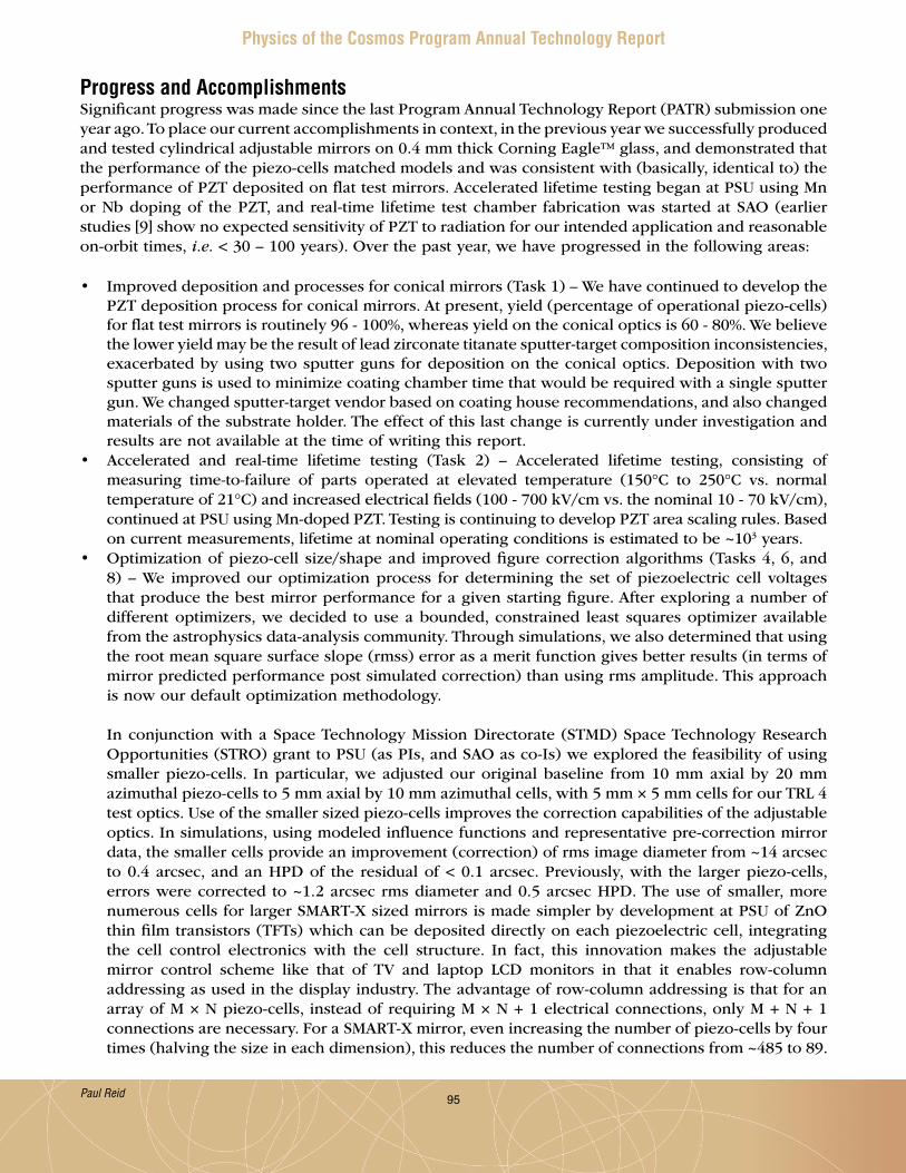
95
Physics of the Cosmos Program Annual Technology Report
Progress and Accomplishments Significant progress was made since the last Program Annual Technology Report (PATR) submission one year ago . To place our current accomplishments in context, in the previous year we successfully produced and tested cylindrical adjustable mirrors on 0 .4 mm thick Corning Eagle™ glass, and demonstrated that the performance of the piezo-cells matched models and was consistent with (basically, identical to) the performance of PZT deposited on flat test mirrors . Accelerated lifetime testing began at PSU using Mn or Nb doping of the PZT, and real-time lifetime test chamber fabrication was started at SAO (earlier studies [9] show no expected sensitivity of PZT to radiation for our intended application and reasonable on-orbit times, i.e. < 30 – 100 years) . Over the past year, we have progressed in the following areas:
• Improved deposition and processes for conical mirrors (Task 1) – We have continued to develop the PZT deposition process for conical mirrors . At present, yield (percentage of operational piezo-cells) for flat test mirrors is routinely 96 - 100%, whereas yield on the conical optics is 60 - 80% . We believe the lower yield may be the result of lead zirconate titanate sputter-target composition inconsistencies, exacerbated by using two sputter guns for deposition on the conical optics . Deposition with two sputter guns is used to minimize coating chamber time that would be required with a single sputter gun . We changed sputter-target vendor based on coating house recommendations, and also changed materials of the substrate holder . The effect of this last change is currently under investigation and results are not available at the time of writing this report .
• Accelerated and real-time lifetime testing (Task 2) – Accelerated lifetime testing, consisting of measuring time-to-failure of parts operated at elevated temperature (150°C to 250°C vs . normal temperature of 21°C) and increased electrical fields (100 - 700 kV/cm vs . the nominal 10 - 70 kV/cm), continued at PSU using Mn-doped PZT . Testing is continuing to develop PZT area scaling rules . Based on current measurements, lifetime at nominal operating conditions is estimated to be ~103 years .
• Optimization of piezo-cell size/shape and improved figure correction algorithms (Tasks 4, 6, and 8) – We improved our optimization process for determining the set of piezoelectric cell voltages that produce the best mirror performance for a given starting figure . After exploring a number of different optimizers, we decided to use a bounded, constrained least squares optimizer available from the astrophysics data-analysis community . Through simulations, we also determined that using the root mean square surface slope (rmss) error as a merit function gives better results (in terms of mirror predicted performance post simulated correction) than using rms amplitude . This approach is now our default optimization methodology .
In conjunction with a Space Technology Mission Directorate (STMD) Space Technology Research Opportunities (STRO) grant to PSU (as PIs, and SAO as co-Is) we explored the feasibility of using smaller piezo-cells . In particular, we adjusted our original baseline from 10 mm axial by 20 mm azimuthal piezo-cells to 5 mm axial by 10 mm azimuthal cells, with 5 mm × 5 mm cells for our TRL 4 test optics . Use of the smaller sized piezo-cells improves the correction capabilities of the adjustable optics . In simulations, using modeled influence functions and representative pre-correction mirror data, the smaller cells provide an improvement (correction) of rms image diameter from ~14 arcsec to 0 .4 arcsec, and an HPD of the residual of < 0 .1 arcsec . Previously, with the larger piezo-cells, errors were corrected to ~1 .2 arcsec rms diameter and 0 .5 arcsec HPD . The use of smaller, more numerous cells for larger SMART-X sized mirrors is made simpler by development at PSU of ZnO thin film transistors (TFTs) which can be deposited directly on each piezoelectric cell, integrating the cell control electronics with the cell structure . In fact, this innovation makes the adjustable mirror control scheme like that of TV and laptop LCD monitors in that it enables row-column addressing as used in the display industry . The advantage of row-column addressing is that for an array of M × N piezo-cells, instead of requiring M × N + 1 electrical connections, only M + N + 1 connections are necessary . For a SMART-X mirror, even increasing the number of piezo-cells by four times (halving the size in each dimension), this reduces the number of connections from ~485 to 89 .
Paul Reid
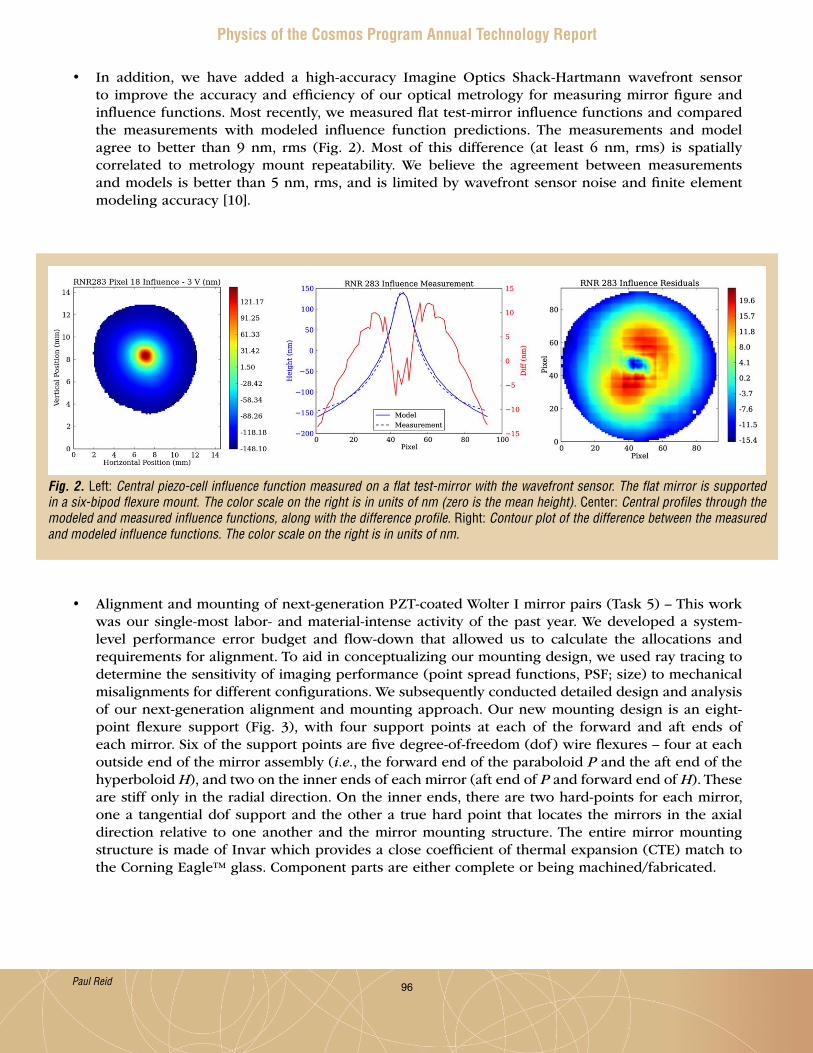
96
Physics of the Cosmos Program Annual Technology Report
• In addition, we have added a high-accuracy Imagine Optics Shack-Hartmann wavefront sensor to improve the accuracy and efficiency of our optical metrology for measuring mirror figure and influence functions . Most recently, we measured flat test-mirror influence functions and compared the measurements with modeled influence function predictions . The measurements and model agree to better than 9 nm, rms (Fig . 2) . Most of this difference (at least 6 nm, rms) is spatially correlated to metrology mount repeatability . We believe the agreement between measurements and models is better than 5 nm, rms, and is limited by wavefront sensor noise and finite element modeling accuracy [10] .
Fig. 2. Left: Central piezo-cell influence function measured on a flat test-mirror with the wavefront sensor. The flat mirror is supported in a six-bipod flexure mount. The color scale on the right is in units of nm (zero is the mean height). Center: Central profiles through the modeled and measured influence functions, along with the difference profile. Right: Contour plot of the difference between the measured and modeled influence functions. The color scale on the right is in units of nm.
• Alignment and mounting of next-generation PZT-coated Wolter I mirror pairs (Task 5) – This work was our single-most labor- and material-intense activity of the past year . We developed a system-level performance error budget and flow-down that allowed us to calculate the allocations and requirements for alignment . To aid in conceptualizing our mounting design, we used ray tracing to determine the sensitivity of imaging performance (point spread functions, PSF; size) to mechanical misalignments for different configurations . We subsequently conducted detailed design and analysis of our next-generation alignment and mounting approach . Our new mounting design is an eight-point flexure support (Fig . 3), with four support points at each of the forward and aft ends of each mirror . Six of the support points are five degree-of-freedom (dof) wire flexures – four at each outside end of the mirror assembly (i.e., the forward end of the paraboloid P and the aft end of the hyperboloid H), and two on the inner ends of each mirror (aft end of P and forward end of H) . These are stiff only in the radial direction . On the inner ends, there are two hard-points for each mirror, one a tangential dof support and the other a true hard point that locates the mirrors in the axial direction relative to one another and the mirror mounting structure . The entire mirror mounting structure is made of Invar which provides a close coefficient of thermal expansion (CTE) match to the Corning Eagle™ glass . Component parts are either complete or being machined/fabricated .
Paul Reid
97
Physics of the Cosmos Program Annual Technology Report
We used ray-tracing-based structural thermal optical performance (STOP) analysis to evaluate the mounting constraints for a variety of “disturbances,” including ambient temperature change of ±2°C;gravity orientation (mirrors will be aligned with the optical axis vertical, but X-ray-tested with the optical axis horizontal in the so-called “parenthesis” configuration); and sensitivity to stray, non-deterministic assembly loads . Lastly, we modeled influence functions for the “TRL 4 test mirrors” in the mount in the parenthesis X-ray test configuration to verify the piezo adjusters can correct for gravity-induced deflections to better than the desired 1 arcsec rms image diameter .
• Actual mirror alignment will use an SAO-designed and built six-axis positioner with feedback control, necessary because off-the-shelf hexapods did not meet our requirements . Our positioner, that we have already started to assemble, will meet the stringent requirements necessary for a 0 .5 arcsec HPD telescope . Alignment metrology will still make use of the scanning Hartmann test Centroid Detector Assembly (CDA, as used for Chandra nee Advanced X-ray Astrophysics Facility, AXAF; and Con-X/IXO) . However, we are making upgrades to the CDA to (1) shorten the laser wavelength being used from 650 nm to 488 nm to reduce diffraction spot size, (2) increase laser power, and (3) resize laser beam divergence to better conform to the adjustable optics/SMART-X mirror size rather than the ~1 m long Chandra optics .
Path Forward• Improve PZT lifetime, yield, and stability (Task 2) – Accelerated lifetime testing will continue at
PSU to properly scale for piezo-cell area . At present, lifetimes, scaled to our nominal operating conditions but not for piezo-cell area, range from 103 to 104 yrs . First, we do not know how the failure rate of small test pixels corresponds to that of the large pixels we will use for the TRL 4 optics, as the exact cause of failure is unknown . To determine the failure mechanism, we will examine the piezoelectric microstructure and incorporate new results from accelerated lifetime tests under different conditions . Second, to increase yield, we are examining the stability and quality of the PZT
Fig. 3. Mirror segment mounting scheme.
Paul Reid

98
Physics of the Cosmos Program Annual Technology Report
sputter-targets (which vary from vendor to vendor) used for deposition . We are also examining a technique for pre-cleaning the sputter-target prior to sputtering . Lastly, we are fully implementing for conical pieces the contamination control procedures we employed with great success on flat test pieces to raise their yield to 100% . With respect to real-time lifetime testing, samples will remain under test until they fail .
• Alignment and mounting of next-generation PZT-coated conical optics (Tasks 1 & 5) – We will first
align and mount thin glass conical optics that have not yet been coated with PZT material . This allows us to prove out our new mounting approach while in parallel we continue to mature the PZT technology at PSU . We will employ a low-resolution Shack Hartman to measure the position of the mirrors while we adjust them to be within the dynamic range of the retrofitted CDA . We will correlate measurements taken during alignment with our Finite Element Analysis (FEA) and ray-trace model predictions as much as practicable . Next calendar year, we will replace these optics with ones coated with PZT material and possessing fully operational piezo-cells . We will then repeat the alignment process in preparation for X-ray testing (Task 7) .
• Figure correction of conical mirrors (Tasks 1, 4, 6, and 8) – We will continue developing figure correction for the APRA-size mirror elements while we continue simulation modeling for SMART-X-sized elements . We plan to power multiple elements simultaneously using a programmable 128-channel voltage controller for experimentation . We will also build a hardwired multichannel voltage controller and a leakage current monitor using precision resistors for TRL 4 test operation . We will fabricate 105 mm (azimuthally wide) × 100 mm (axially long) conical mirror segments with 5 mm × 5 mm piezoelectric cells (1 .5 µm thick PZT) . Our simulations also show the smaller the “inactive” gap between piezo-cells, where we currently locate electrical traces, the better the error correction and performance . We will explore minimizing the gap by depositing an insulating layer on top of the top electrodes, with “vias” through the insulating layer to provide electrical contact to the electrodes . Lithographic, thin conductive traces will run from the azimuthal edges of the mirror segments to each piezo-cell contact . This will enable us to reduce the gap between piezo-cells from the 1 mm we modeled for TRL 4 to the ~0 .2 mm we modeled for SMART-X .
• X-ray Characterization (Task 7) – We will align and mount a paraboloid-hyperboloid pair of adjustable mirrors, measure and correct figure error, and characterize in X-rays at the MSFC 100 m X-ray beam-line . Successfully demonstrating the ability to control and correct mirror figure consistent with 1 arcsec rms image diameter performance will, in our opinion, demonstrate TRL 4 .
Miscellaneous – SAO continues to show strong institutional support for the adjustable X-ray optics program, providing funds for internal research and development activities in addition to creating a three-year postdoctoral fellowship – the Leon Van Speybroeck Fellowship in X-ray Optics . This institutional support has helped us advance ahead of schedule and reduce overall project risk .
References[1] Vikhlinin, A ., et al., “SMART-X: Square Meter Arcsecond Resolution x-ray Telescope,” SPIE Proc .
8443, 844316 (2012) .[2] Aldcroft, T ., et al., “Simulating correction of adjustable optics for an X-ray telescope,” SPIE Proc .
8503, 85030F (2012) .[3] Zhang, W . W ., et al., “Lightweight and high angular resolution x-ray optics for astronomical
missions,” SPIE Proc . 8147, 81470K (2011) .[4] Feldman, C ., et al., “The performance of thin shell adaptive optics for high angular resolution
x-ray telescopes,” SPIE Proc . 7803, 78030N (2010) .
Paul Reid

99
Physics of the Cosmos Program Annual Technology Report
[5] Reid, P .B ., et al., “Technology development of adjustable grazing incidence X-ray optics for sub-arc second imaging,” SPIE Proc . 8443, 84430T (2012) .
[6] Wilke, R .H .T ., et al., “Sputter deposition of PZT Perovskite Films on Thin Glass Substrates for Adjustable X-ray Optics,” Appl . Opt . 52, 3412 (2013) .
[7] Cotroneo, V ., et al., “Adjustable grazing incidence X-ray optics based upon thin PZT film,” SPIE Proc . 8503, 850309 (2012) .
[8] Johnson-Wilke, R ., et al., “Improving yield of PZT piezoelectric devices on glass substrates,” SPIE Proc . 8503, 85030A (2012) .
[9] Miyahira, T .F ., et al., “Total Dose Degradation of MEMS Optical Mirrors,” IEEE Trans . Nucl . Sci . 50, 1860 (2003) .
[10] Allured, R ., et al., “Measuring the performance of adjustable X-ray optics with wavefront sensing,” SPIE Proc . 9144, in press (2014) .
For additional information, contact Paul Reid: [email protected]
Paul Reid
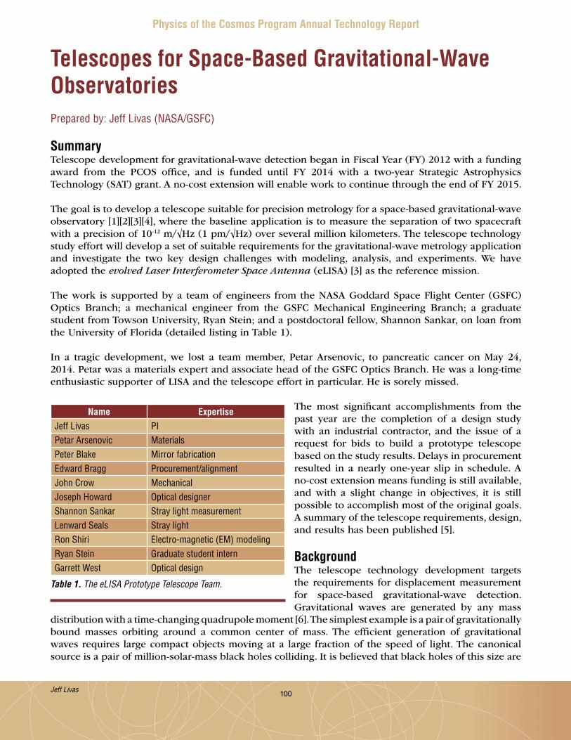
100
Physics of the Cosmos Program Annual Technology Report
Telescopes for Space-Based Gravitational-Wave ObservatoriesPrepared by: Jeff Livas (NASA/GSFC)
SummaryTelescope development for gravitational-wave detection began in Fiscal Year (FY) 2012 with a funding award from the PCOS office, and is funded until FY 2014 with a two-year Strategic Astrophysics Technology (SAT) grant . A no-cost extension will enable work to continue through the end of FY 2015 .
The goal is to develop a telescope suitable for precision metrology for a space-based gravitational-wave observatory [1][2][3][4], where the baseline application is to measure the separation of two spacecraft with a precision of 10-12 m/√Hz (1 pm/√Hz) over several million kilometers . The telescope technology study effort will develop a set of suitable requirements for the gravitational-wave metrology application and investigate the two key design challenges with modeling, analysis, and experiments . We have adopted the evolved Laser Interferometer Space Antenna (eLISA) [3] as the reference mission .
The work is supported by a team of engineers from the NASA Goddard Space Flight Center (GSFC) Optics Branch; a mechanical engineer from the GSFC Mechanical Engineering Branch; a graduate student from Towson University, Ryan Stein; and a postdoctoral fellow, Shannon Sankar, on loan from the University of Florida (detailed listing in Table 1) .
In a tragic development, we lost a team member, Petar Arsenovic, to pancreatic cancer on May 24, 2014 . Petar was a materials expert and associate head of the GSFC Optics Branch . He was a long-time enthusiastic supporter of LISA and the telescope effort in particular . He is sorely missed .
The most significant accomplishments from the past year are the completion of a design study with an industrial contractor, and the issue of a request for bids to build a prototype telescope based on the study results . Delays in procurement resulted in a nearly one-year slip in schedule . A no-cost extension means funding is still available, and with a slight change in objectives, it is still possible to accomplish most of the original goals . A summary of the telescope requirements, design, and results has been published [5] .
BackgroundThe telescope technology development targets the requirements for displacement measurement for space-based gravitational-wave detection . Gravitational waves are generated by any mass
distribution with a time-changing quadrupole moment [6] . The simplest example is a pair of gravitationally bound masses orbiting around a common center of mass . The efficient generation of gravitational waves requires large compact objects moving at a large fraction of the speed of light . The canonical source is a pair of million-solar-mass black holes colliding . It is believed that black holes of this size are
Table 1. The eLISA Prototype Telescope Team.
Name ExpertiseJeff Livas PIPetar Arsenovic MaterialsPeter Blake Mirror fabricationEdward Bragg Procurement/alignmentJohn Crow MechanicalJoseph Howard Optical designerShannon Sankar Stray light measurementLenward Seals Stray lightRon Shiri Electro-magnetic (EM) modelingRyan Stein Graduate student internGarrett West Optical design
Jeff Livas
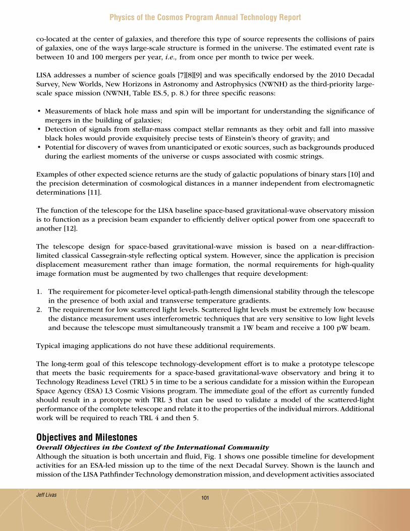
101
Physics of the Cosmos Program Annual Technology Report
co-located at the center of galaxies, and therefore this type of source represents the collisions of pairs of galaxies, one of the ways large-scale structure is formed in the universe . The estimated event rate is between 10 and 100 mergers per year, i.e., from once per month to twice per week .
LISA addresses a number of science goals [7][8][9] and was specifically endorsed by the 2010 Decadal Survey, New Worlds, New Horizons in Astronomy and Astrophysics (NWNH) as the third-priority large-scale space mission (NWNH, Table ES .5, p . 8 .) for three specific reasons:
• Measurements of black hole mass and spin will be important for understanding the significance of mergers in the building of galaxies;
• Detection of signals from stellar-mass compact stellar remnants as they orbit and fall into massive black holes would provide exquisitely precise tests of Einstein’s theory of gravity; and
• Potential for discovery of waves from unanticipated or exotic sources, such as backgrounds produced during the earliest moments of the universe or cusps associated with cosmic strings .
Examples of other expected science returns are the study of galactic populations of binary stars [10] and the precision determination of cosmological distances in a manner independent from electromagnetic determinations [11] .
The function of the telescope for the LISA baseline space-based gravitational-wave observatory mission is to function as a precision beam expander to efficiently deliver optical power from one spacecraft to another [12] .
The telescope design for space-based gravitational-wave mission is based on a near-diffraction-limited classical Cassegrain-style reflecting optical system . However, since the application is precision displacement measurement rather than image formation, the normal requirements for high-quality image formation must be augmented by two challenges that require development:
1 . The requirement for picometer-level optical-path-length dimensional stability through the telescope in the presence of both axial and transverse temperature gradients .
2 . The requirement for low scattered light levels . Scattered light levels must be extremely low because the distance measurement uses interferometric techniques that are very sensitive to low light levels and because the telescope must simultaneously transmit a 1W beam and receive a 100 pW beam .
Typical imaging applications do not have these additional requirements .
The long-term goal of this telescope technology-development effort is to make a prototype telescope that meets the basic requirements for a space-based gravitational-wave observatory and bring it to Technology Readiness Level (TRL) 5 in time to be a serious candidate for a mission within the European Space Agency (ESA) L3 Cosmic Visions program . The immediate goal of the effort as currently funded should result in a prototype with TRL 3 that can be used to validate a model of the scattered-light performance of the complete telescope and relate it to the properties of the individual mirrors . Additional work will be required to reach TRL 4 and then 5 .
Objectives and MilestonesOverall Objectives in the Context of the International CommunityAlthough the situation is both uncertain and fluid, Fig . 1 shows one possible timeline for development activities for an ESA-led mission up to the time of the next Decadal Survey . Shown is the launch and mission of the LISA Pathfinder Technology demonstration mission, and development activities associated
Jeff Livas
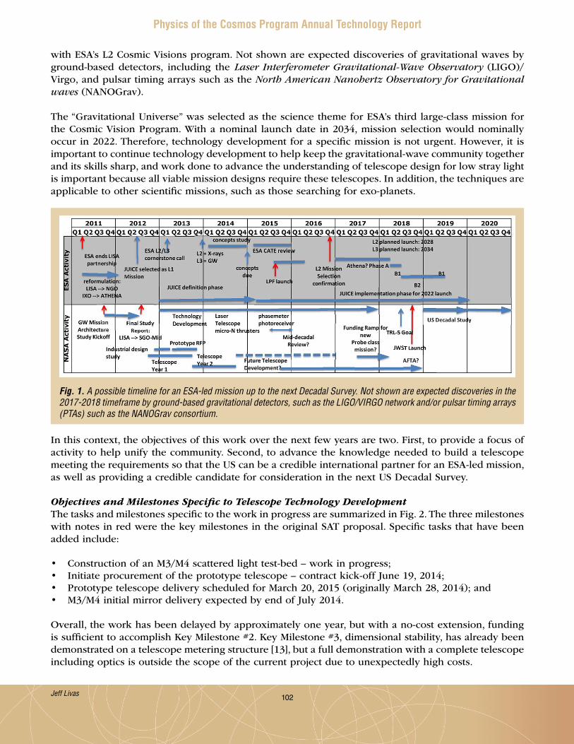
102
Physics of the Cosmos Program Annual Technology Report
with ESA’s L2 Cosmic Visions program . Not shown are expected discoveries of gravitational waves by ground-based detectors, including the Laser Interferometer Gravitational-Wave Observatory (LIGO)/Virgo, and pulsar timing arrays such as the North American Nanohertz Observatory for Gravitational waves (NANOGrav) .
The “Gravitational Universe” was selected as the science theme for ESA’s third large-class mission for the Cosmic Vision Program . With a nominal launch date in 2034, mission selection would nominally occur in 2022 . Therefore, technology development for a specific mission is not urgent . However, it is important to continue technology development to help keep the gravitational-wave community together and its skills sharp, and work done to advance the understanding of telescope design for low stray light is important because all viable mission designs require these telescopes . In addition, the techniques are applicable to other scientific missions, such as those searching for exo-planets .
In this context, the objectives of this work over the next few years are two . First, to provide a focus of activity to help unify the community . Second, to advance the knowledge needed to build a telescope meeting the requirements so that the US can be a credible international partner for an ESA-led mission, as well as providing a credible candidate for consideration in the next US Decadal Survey .
Objectives and Milestones Specific to Telescope Technology DevelopmentThe tasks and milestones specific to the work in progress are summarized in Fig . 2 . The three milestones with notes in red were the key milestones in the original SAT proposal . Specific tasks that have been added include:
• Construction of an M3/M4 scattered light test-bed – work in progress;• Initiate procurement of the prototype telescope – contract kick-off June 19, 2014;• Prototype telescope delivery scheduled for March 20, 2015 (originally March 28, 2014); and• M3/M4 initial mirror delivery expected by end of July 2014 .
Overall, the work has been delayed by approximately one year, but with a no-cost extension, funding is sufficient to accomplish Key Milestone #2 . Key Milestone #3, dimensional stability, has already been demonstrated on a telescope metering structure [13], but a full demonstration with a complete telescope including optics is outside the scope of the current project due to unexpectedly high costs .
Fig. 1. A possible timeline for an ESA-led mission up to the next Decadal Survey. Not shown are expected discoveries in the 2017-2018 timeframe by ground-based gravitational detectors, such as the LIGO/VIRGO network and/or pulsar timing arrays (PTAs) such as the NANOGrav consortium.
Jeff Livas

103
Physics of the Cosmos Program Annual Technology Report
Progress and AccomplishmentsPrevious AccomplishmentsThe major accomplishment during 2012-2013 was to complete a study of the telescope design with an industrial contractor . The study included a complete thermal, optical, and a partial mechanical analysis of two implementations – an on-axis design and an off-axis design, and two material systems – carbon fiber composite, and silicon carbide . The study contractor was also required to develop plans for manufacturing and verification testing of these designs . The main results and recommendations are summarized below .
• Use an off-axis design for best stray light performance (on- vs off-axis manufacturing complexity is similar);
• Use silicon carbide to avoid the unknown effects on dimensional stability from water absorption and subsequent out-gassing with composite materials; and
• A cost estimate for a ground prototype was $2 .5M, including: $1 .5M recurring engineering; $0 .26M non-recurring engineering; $0 .43M testing; $0 .22M focus mechanism; and 16-month delivery .
Fig. 2. Key project tasks and milestones. The three original key milestones are flagged with bold red numbers on the right-hand border of the schedule. See Table 2 for the redefined milestones.
Jeff Livas

104
Physics of the Cosmos Program Annual Technology Report
Recent AccomplishmentsAccomplishments and activities over the past year fall into two different categories – prototype telescope and scattered-light suppression .
Immediately after the study concluded on April 11, 2013, we initiated a request for quotes (RFQ) for building a prototype telescope based on the study results . The RFQ process ended October 24, 2013 with two bids . The lowest bid was approximately twice the available funding, and the proposal was not adequate technically . The other bid was about four times the available funding . At this point, we were forced to de-scope the work to extract the most value . We chose to concentrate on developing and validating a scattered light model, rather than achieving a specific performance level for scattered light . This amounts to a redefinition of Key Milestone 2 (Table 2) . In addition, we had to postpone testing the complete telescope for dimensional stability since cost considerations forced us to choose materials for a room-temperature test-bed instead of the expected soak temperature of -70°C . We previously investigated silicon carbide for the metering structure and showed it can be stable enough, so it seemed best to develop experience with scattered light .
Year Milestone Date Milestone Description Redefinition New DateFY 2013 1 9/13 Stray light measurement
capabilityNo redefinition – achieved. Demonstrated dynamic range of 10-10
Achieved
FY 2014 2 3/14 Demonstration of scattered light performance of <10-10 of transmit power
Develop and validate a scattered light model
9/15
FY 2014 3 9/14 Demonstration of optical-path-length stability
Not possible – materials and construction of a prototype that could be environmentally tested are too expensive
N/A
Table 2. Key milestones as redefined.
Mirror Surface Roughness Coating Delivery (Uncoated)M3/M4 < 5 Å rms HR+IBS 8/6/2014M3/M4 < 5 Å rms IBS 7/7/2014
M3 < 1 Å rms IBS 8/18/2014M1/M2 < 15 Å rms HR 11/21/2014
Table 3. Summary of mirrors on order. “HR” is a high reflectivity coating with R > 99.5%. “IBS” is an ion beam sputtered coating with R > 99.99% (IBS coating of all relevant mirrors currently expected to be completed 11/30/2014).
We were able to find a vendor who agreed to build a complete prototype telescope to meet our requirements at room temperature, and we held a kick-off meeting on June 19, 2014, with an expected delivery date of March 20, 2015 . We will supply a set of mirrors as Government Furnished Equipment (GFE) .
In parallel with the construction of a complete telescope, we designed a test-bed consisting of just M3 and M4 where we can test those two mirrors individually and as a subsystem .
We modified the telescope design from the study contractor, simplifying it while retaining its essential features, then designed the mirrors . We ordered a complete set of mirrors to build a prototype, as well as several sets of the two mirrors the model shows are the largest sources of scattered light, M3 and M4 . The idea is to try different combinations of surface roughness and coatings (Table 3) to better understand how to achieve the scattered light requirement and demonstrate we understand the physics .
Jeff Livas

105
Physics of the Cosmos Program Annual Technology Report
We also identified a facility, run by Robert Gorman of the GSFC Contamination and Coatings Engineering Branch, with equipment in a clean room that can make Bi-directional Reflectance Distribution Function (BRDF) measurements of individual mirrors . We are working with Robert to add the capability to make measurements at 1064 nm, the operating wavelength for gravitational-wave detectors .
Scattered-light suppression work was augmented with funding received by Ron Shiri through the Goddard Internal Research and Development (IRAD) program for development of partially transparent petaled masks . This funding enabled Ron to engage with the University of Delaware for fabrication of partially transparent masks . Ron also set up a collaboration with Professor Wasylkiwskyj for diffraction calculations to support the effort .
Experimental efforts continue with Shannon Sankar and Ryan Stein making transmission measurements of the petaled masks designed by Ron . Diffraction from a circular aperture or mirror with a smooth edge produces a bright spot on axis, right where the detector would be (Fig . 3, left) . Breaking up the smooth edge with petals suppresses the on-axis power (Fig . 3, right) . The measured suppression is less than expected, and we have identified several causes .
Fig. 3. Diffraction from a smooth edge (top left) produces a bright spot on axis where a detector would be placed (bottom left). A petaled mask (top right) suppresses the on-axis spot (bottom right).
Jeff Livas
106
Physics of the Cosmos Program Annual Technology Report
One cause of insufficient suppression is that the films used to make the petaled masks are so thin that there is approximately 25% transmission through the masks, directly degrading on-axis performance .Another cause is interference fringes from the substrate . We applied an anti-reflection (AR) coating, but the AR coatings were fabricated incorrectly and the minimum in reflectivity was not at 1064 nm . We also successfully applied a digital image filter to remove the fringes, but a better approach is to make the masks on a substrate with a slight wedge angle to prevent the fringes in the first place, an approach we are currently pursuing . Successful implementation of these masks may allow us to adopt an on-axis telescope design, which may be less expensive to build and better-suited to the environmental requirements of the application than an off-axis design .
Path ForwardThe key milestones for the project are shown in Table 2 as originally proposed for the SAT grant . The first milestone is to demonstrate the ability to detect low levels of scattered light . This was successfully accomplished in the summer of 2013 .
The second milestone is to demonstrate low-scattered-light performance with a prototype telescope . The current schedule calls for the telescope to be delivered at the end of March 2015, later than the original date shown . It may require several months to measure the properties of the individual mirrors and then the performance of the complete telescope . The new estimated completion date is September 2015 .
As described in the previous section, we intend to begin making measurements of scattered-light performance with a test-bed containing only M3 and M4, which we believe are the largest contributors to scattered light from the telescope . The mechanical pieces of the test-bed should be assembled by the end of July 2014, and the mirrors should all arrive by the beginning of September 2014 . We may therefore have preliminary measurements of scattered-light performance by the end of 2015 .
The third milestone is to demonstrate the optical-path-length stability requirement . This milestone is currently outside the capability of this development effort . It is not necessary to develop the path-length stability measurement capability because the original plan was to take advantage of the capability already developed for measuring a silicon carbide spacer at the University of Florida [13][14][15] . In practice, some work will be required to adapt the existing setup to a real telescope with optics instead of just a metering structure, and to improve the temperature measurement instrumentation, but the basic capability exists . A second iteration of the prototype telescope with more flight-like materials will be required to demonstrate dimensional stability . Figure 1 shows the context and an estimate of the timing and schedule of the additional work . This second iteration is not currently funded, and would be undertaken ideally as follow-on work to the current grant, or later as time and funding permit .
AcknowledgementsThe author would like to thank P . Bender, G . Mueller, J . Sanjuan, A . Spector, R . Stebbins, and the members of the Gravitational-Wave Study Team for advice, support, and stimulating discussions .
References[1] P . Bender, K . Danzmann, and LISA Study Team, “LISA for the Detection and Observation of
Gravitational Waves,” Max-Planck-Institut fur Quantenoptik, Garching Technical Report No . MPQ233 (1998) (http://lisa .gsfc .nasa .gov/Documentation/ppa2 .08 .pdf)
[2] LISA assessment study report (Yellow Book), ESA/SRE (2011) 3, (http://sci .esa .int/lisa/48364-lisa-assessment-study-report-yellow-book/) .
[3] eLISA L2 White Paper (https://www .elisascience .org/articles/elisa-mission/elisa-l2-white-paper) .
Jeff Livas

107
Physics of the Cosmos Program Annual Technology Report
[4] Gravitational-Wave Mission Concept Study Final Report, (http://pcos .gsfc .nasa .gov/physpag/GW_Study_Rev3_Aug2012-Final .pdf)
[5] J . Livas, P . Arsenovic, J . Crow, P . Hill, J . Howard, L . Seals, S . Shiri, “Telescopes for Space-based Gravitational Wave Missions,” Opt . Eng . 53 (9), 091811 (2013) . doi: 10 .1117/1 .OE .52 .9 .091811
[6] B . Schutz, “Gravitational waves on the back of an envelope,” Am . J . Phys . 52 412 (1984) .[7] P . Amaor-Seoane, et al., “Low-frequency gravitational-wave science with eLISA/NGO,” Class .
Quantum Grav . 29 (12), 124016 (2012) .[8] P . Amaro-Seoane, et al., “Intermediate and extreme mass-ratio inspiral astrophysics, science
applications, and detection using LISA,” Class . Quantum Grav . 24 (17) (2007) .[9] A . Stroeer and A . Vecchio, “The LISA verification binaries,” Class . Quantum Grav . 23 S809-S817,
(2006) .[10] S . Nissanke, et al., “Gravitational-wave emission from compact Galactic binaries,” Astrophys .
J .758 (131) (2012) .[11] C . Cutler and D . Holz, “Ultra-high precision cosmology from gravitational waves,” Phys . Rev . D 80,
104009 (2009) .[12] O . Jennrich, “LISA technology and instrumentation,” Class . Quantum Grav . 26 (15) 153001 (2009) .
(http://stacks .iop .org/0264-9381/26/i=15/a=153001) .[13] J . Sanjuan, et al., “Note: Silicon carbide telescope dimensional stability for space-based gravitational
wave detectors,” Rev . Sci . Instrum . 83 (11), 116107 (2012) .[14] J . Sanjuan, et al., “Carbon fiber reinforced polymer dimensional stability investigations for use
on the laser interferometric space antenna mission telescope,” Rev Sci . Instrum . 82 (12), 124501 (2011) (http://link .aip .org/link/?RSI/82/124501) DOI: 10 .1063/1 .3662470
[15] A . Preston, “Stability of materials for use in space-based interferometric missions,” Ph .D . Dissertation, University of Florida (2010) .
For additional information, contact Jeff Livas: [email protected]
Jeff Livas

108
Physics of the Cosmos Program Annual Technology Report
Laser Frequency StabilizationPrepared by: John Lipa (Stanford University)
SummaryMissions such as the Laser Interferometer Space Antenna (LISA) and the Space-Time Asymmetry Research (STAR) mission [1] [2], require the ultimate in laser stability . Highly stable lasers are also important for a number of other astrophysical and fundamental physics missions that have been proposed, from the Gravity Recovery and Climate Experiment II (GRACE-II) to the Laser Astrometric Test of Relativity (LATOR) [3], and more recent alternatives to LISA .
When combined with a space-qualified optical frequency comb (currently under development at the Jet Propulsion Laboratory [4]), extremely-high-sensitivity spectroscopy over the entire near-infrared band is possible . This allows easy detection of trace gases in acquired samples, such as within the International Space Station, from a cometary surface, or with a Mars rover, achieving sensitivities up to 100 times that of conventional techniques [5] . This technology could also contribute to crew safety via early fire detection on long duration missions, and improve exploration capability in distant environments . The capability would also be available for ground applications such as advanced atomic clocks, gravity gradiometers, and optical frequency standards . Other longer-range uses include medical applications, such as detection of volatile organic compounds for cancer screening and forensics, and in trace atmospheric gas studies using Light Detection and Ranging (LIDAR) [6] .
Our technical objective is to advance the development of a laser stabilization scheme with very low noise into a low-power, compact unit that can be used in space for missions requiring extreme performance in optical frequency stabilization . The device will operate at a wavelength near 1568 nm using low-pressure carbon monoxide (CO) gas as a molecular reference, with the possibility of migrating to near 1064 nm at a later date . The core technology has been demonstrated in the laboratory over the past 15 years . The ultimate performance as a stabilization system using CO is based on calculation, and is expected to approach the performance of ultra-cold neutral atom clocks requiring multiple lasers and an extensive amount of equipment . The much lighter, simpler package we propose will allow realization of a more practical ultra-stable optical reference for space use .
Our project objectives are:
1 . Demonstrate the lowest short-term noise performance to date using a molecular gas transition as reference medium .
2 . Upgrade the device design from the optical bench level toward a brass-board level, focusing on compactness, power, and portability .
Our team consists of the Principal Investigator and members of Stanford University’s optics groups, with consulting from Prof . Jan Hall of the Joint Institute for Laboratory Astrophysics . Project start date was January 1, 2013 with a two-year period of performance .
The main accomplishment for the past year has been to fabricate and demonstrate functionality of the entire laser stabilization system and achieve operating conditions for low-noise performance .
BackgroundThis project supports the goals of astrophysics by raising the Technology Readiness Level (TRL) of hardware that will increase our knowledge of fundamental laws of nature by providing improved laser
John Lipa

109
Physics of the Cosmos Program Annual Technology Report
frequency stability for use in space missions . It directly supports the Strategic Astrophysics Technology (SAT) program “Physics of the Cosmos” (PCOS) theme . When applied in new space missions, the technology would have a direct impact on cosmology and astrophysics by improving our knowledge of the physics of the early universe . The primary NASA science question supported by this project is given in the 2010 Science Plan for the Science Mission Directorate (SMD): “How do matter, energy, space, and time behave under the extraordinarily diverse conditions of the cosmos?” This is derived from the goal: “Discover how the universe works, explore how the universe began and developed…” Our objective is to develop an extremely stable laser using advanced molecular transition interrogation techniques . The instrument can support improved signal/noise in gravitational-wave detection, scientific measurements related to the isotropy of space and the variation of clock frequencies with gravitational potential, and frontiers of research in testing the limits of Einstein’s theories of space, time, and gravity .
The second Baseline Objective for Astrophysics in the NASA Science Plan for 2007-2016 is: “Investigate the nature of space-time through tests of fundamental symmetries.” Improved laser stability is an important aspect of technology development to support this objective . In the case of the search for Lorentz violations in the velocity of light due to boost, one needs to compare a cavity ‘clock’ with another reference such as a spectral line . This is the modern analog of the Kennedy-Thorndike experiment [7], one of the essential experimental foundations of special relativity . Atomic or molecular clock stability and noise performance are critical features of such an experiment . Hardware development for a space experiment of this type is proceeding at a low level as the STAR program, mentioned earlier .
Our project supports the NRC 2010 Decadal Survey, New Worlds, New Horizons in Astronomy and Astrophysics (NWNH), via improved technology for gravitational-wave detection in space . LISA requirements appear to be satisfied with free-running YAG lasers [8] using a combination of time-delay interferometry [9] and arm-locking [10] . However, it should be remembered that 14 orders of magnitude noise reduction is needed for a free-running laser to make the measurements, a tall order for any electronic processing system . A prudent design would carry a very high margin of safety for dealing with real-world electronics issues on the LISA spacecraft . With the elimination of the American contribution to LISA and the search for cheaper alternatives by the community science and core teams established by the PCOS Program Office, it is clear that improved lasers would lessen the strain on some of the electronic systems contributing to the overall error budget . This would then allow a wider trade space to potentially reduce mission cost and architecture complexity, for example by using a shorter baseline than LISA, but with improved strain resolution .
Improved frequency stabilization using molecular gases allows lower noise measurements or shorter measurement times for various physical phenomena . We project a theoretical improvement of up to a factor of 50 in noise reduction for measurement times of up to 104 sec using a CO molecular-referenced laser as opposed to an iodine-stabilized laser, the current state-of-the-art . An example of the current status of iodine-laser frequency control is given in Argence et al. [11] . The demonstrated noise performance of this iodine system ‘meets’ LISA specs but requires 14 orders of magnitude further noise reduction using interferometry and arm-locking techniques . Our approach tries to reduce the basic laser noise further, allowing some relaxation of signal processing requirements and broadening the trade space for the optics system . An essential feature of our approach is the use of cavity resonance techniques to enhance the signal from a low-pressure gas sample with a very narrow molecular transition line-width . The top-level development plan is to develop the spectroscopy setup for the CO transition of interest at the laboratory instrument level, then transition to a design closer to flight prototype level, on which the desired performance can be demonstrated .
John Lipa

110
Physics of the Cosmos Program Annual Technology Report
Objectives and MilestonesThe overall aim of our work is to develop greatly improved laser frequency stabilization using a molecular gas . The intent is to advance the state of the art from TRL 3 to 4+ . The approach is to use a resonant optical cavity to amplify the optical field applied to a low-pressure gas contained in a specially designed cell and create the conditions for very-high-resolution molecular spectroscopy . The spectroscopy signal is then used to lock the laser frequency to a quantum mechanical transition in the molecule .
The work is loosely divided into four main phases . The first phase involved setting up a basic bench-top spectroscopy system operating with a CO gas cell . This part was completed on schedule . We also set up a medium-finesse UltraLow Expansion (ULE) cavity and thermal control system to act as a short-term optical reference system . This system has now been integrated into the main optics assembly and testing has commenced .
The second phase involves converting the instrument to the breadboard level . The optics system will be repackaged into a more compact, portable instrument . The first components of this system have been completed . This involves placing an optical cavity in a vacuum chamber to establish proper thermal control of critical optical components . This setup is not intended to replicate the vacuum environment of space, but to eliminate conductive and convective heat transfer, reducing thermal drift and frequency fluctuations from air gaps in the optics . It will not include most components of the system because they are commercial parts, not designed for use in vacuum . Nevertheless, the planned vacuum testing will give some information related to space operation .
In the third phase, the portable breadboard system will be extensively operated to demonstrate functionality and start performance testing . To demonstrate frequency stability performance, we must set up a second unit and perform comparison measurements . This will either be fabricated from the bench-top system by converting its optics to work with a second integrated gas cell, or involve an upgrade of the reference cavity to lower-loss mirrors . System response to thermal variations will be measured by comparing the frequency of the system under test with that of the reference system . Testing will be documented to the level required to allow performance predictions in the final operating environment .
In the final phase, the portable breadboard unit will be upgraded using the lessons learned to date, and some critical electronics items will be implemented at the board level . Some of this work will be started in the second and third phases, if manpower loading allows . To minimize unnecessary development effort, board-level work will be restricted to functions not already demonstrated elsewhere at TRL 5 or above . For example, we will not build power supplies, RF drivers, computer boards, frequency counters, etc ., all of which have been demonstrated by other programs . However, we do plan to interface to them so we can operate the setup under laboratory computer control . Software drivers will be written in LabView . The system will be upgraded as close to brass-board level as possible within time and budget constraints . Testing and upgrading is expected to be a continuous process during this period . A major technology milestone in this phase will be performance demonstration at a fractional frequency stability δf/f of 2×10-15 or better with 1 sec averaging . This is about seven times the estimated photon noise-limited performance with CO, and an order of magnitude better than iodine .
Key Milestones Status1 . First turn-on of complete bench-top system completed June 20132 . First turn-on of optical cavity reference setup completed Oct . 20133 . Bench-top system operational with CO (in progress) Aug . 20144 . Completion of flight prototype gas cell completed May 20145 . Completion of breadboard instrument assembly (in progress) Sep . 2014 6 . Start testing in vacuum environment Sep . 2014
John Lipa

111
Physics of the Cosmos Program Annual Technology Report
7 . Complete first round of vacuum testing Oct . 20148 . Complete upgrade of bench-top system (in progress) Aug . 20149 . Complete breadboard performance testing Nov . 201410 . Complete breadboard frequency stability testing in vacuum Dec . 2014
Milestones 5 – 8 have slipped somewhat compared to last year’s plan due to technical difficulties with vendor-supplied components and problems developing suitable low-loss resonant gas cells . As described below we have overcome these challenges and are now able to demonstrate all technical requirements for the planned measurements . Our budget situation remains healthy and staffing appears adequate .
Progress and Accomplishments The past 12 months of the project have seen significant progress on setting up the bench-top version of the CO laser stabilization system, also known as the molecular clock . This work proceeded in two main phases – design and fabrication of the bench-top optical cell assembly, and assembly of the associated opto-electronics . All optical fabrication has been completed and we are in the final stages of testing the electronics . The initial version of the bench-top optical cavity and cell assembly (Fig . 1) consists of a custom-built invar frame surrounding a CO gas cell with high-finesse mirrors on either end, attached to piezoelectric transducers .
Fig. 1. Optical cavity #1.
John Lipa
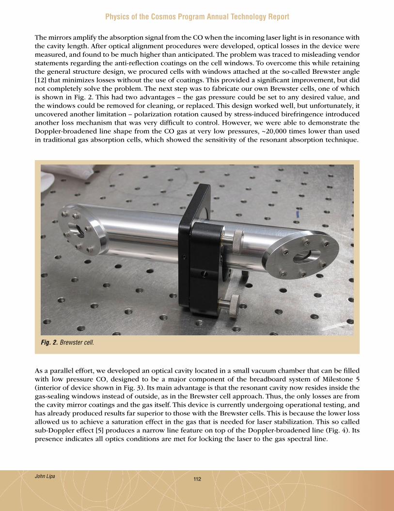
112
Physics of the Cosmos Program Annual Technology Report
The mirrors amplify the absorption signal from the CO when the incoming laser light is in resonance with the cavity length . After optical alignment procedures were developed, optical losses in the device were measured, and found to be much higher than anticipated . The problem was traced to misleading vendor statements regarding the anti-reflection coatings on the cell windows . To overcome this while retaining the general structure design, we procured cells with windows attached at the so-called Brewster angle [12] that minimizes losses without the use of coatings . This provided a significant improvement, but did not completely solve the problem . The next step was to fabricate our own Brewster cells, one of which is shown in Fig . 2 . This had two advantages – the gas pressure could be set to any desired value, and the windows could be removed for cleaning, or replaced . This design worked well, but unfortunately, it uncovered another limitation – polarization rotation caused by stress-induced birefringence introduced another loss mechanism that was very difficult to control . However, we were able to demonstrate the Doppler-broadened line shape from the CO gas at very low pressures, ~20,000 times lower than used in traditional gas absorption cells, which showed the sensitivity of the resonant absorption technique .
Fig. 2. Brewster cell.
As a parallel effort, we developed an optical cavity located in a small vacuum chamber that can be filled with low pressure CO, designed to be a major component of the breadboard system of Milestone 5 (interior of device shown in Fig . 3) . Its main advantage is that the resonant cavity now resides inside the gas-sealing windows instead of outside, as in the Brewster cell approach . Thus, the only losses are from the cavity mirror coatings and the gas itself . This device is currently undergoing operational testing, and has already produced results far superior to those with the Brewster cells . This is because the lower loss allowed us to achieve a saturation effect in the gas that is needed for laser stabilization . This so called sub-Doppler effect [5] produces a narrow line feature on top of the Doppler-broadened line (Fig . 4) . Its presence indicates all optics conditions are met for locking the laser to the gas spectral line .
John Lipa

113
Physics of the Cosmos Program Annual Technology Report
The associated opto-electronics consists of multiple commercial optical components operating at a wavelength of 1568 nm, mounted on a highly stable optical table . In the section near the laser, the components are fiber-coupled, while near the optical cell they are free-space-coupled . A schematic of the optical layout is shown in Fig . 5, including the feedback loops controlling the optical frequency . With the advent of the new optical cavity (Fig . 3), we need to change the operating frequency of one of the feedback loops from 430 MHz to 580 MHz, requiring new commercial components . These are currently in procurement . With this exception, all components are now operational . The 430 MHz loop was demonstrated on the original optical cavity . Feedback signals are generated digitally using a commercial data acquisition and control system running LabView code .
Fig. 3. Optical cavity #2 partially assembled.
John Lipa
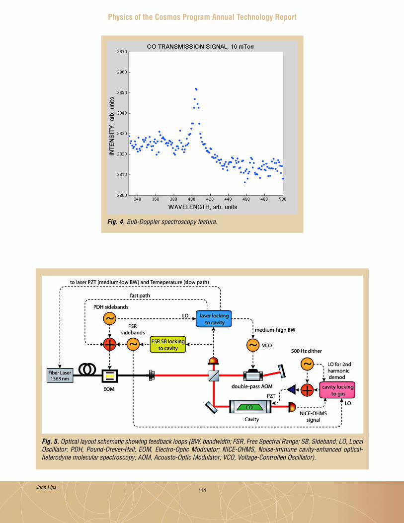
114
Physics of the Cosmos Program Annual Technology Report
Fig. 4. Sub-Doppler spectroscopy feature.
Fig. 5. Optical layout schematic showing feedback loops (BW, bandwidth; FSR, Free Spectral Range; SB, Sideband; LO, Local Oscillator; PDH, Pound-Drever-Hall; EOM, Electro-Optic Modulator; NICE-OHMS, Noise-immune cavity-enhanced optical-heterodyne molecular spectroscopy; AOM, Acousto-Optic Modulator; VCO, Voltage-Controlled Oscillator).
John Lipa
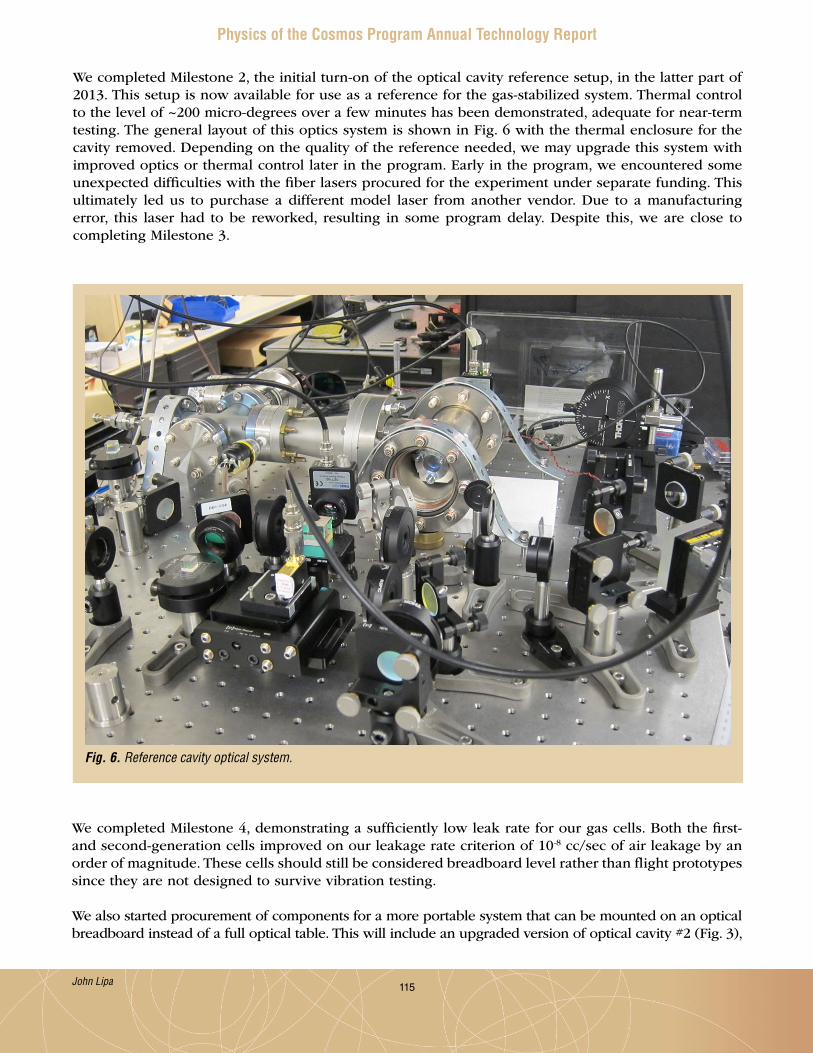
115
Physics of the Cosmos Program Annual Technology Report
We completed Milestone 2, the initial turn-on of the optical cavity reference setup, in the latter part of 2013 . This setup is now available for use as a reference for the gas-stabilized system . Thermal control to the level of ~200 micro-degrees over a few minutes has been demonstrated, adequate for near-term testing . The general layout of this optics system is shown in Fig . 6 with the thermal enclosure for the cavity removed . Depending on the quality of the reference needed, we may upgrade this system with improved optics or thermal control later in the program . Early in the program, we encountered some unexpected difficulties with the fiber lasers procured for the experiment under separate funding . This ultimately led us to purchase a different model laser from another vendor . Due to a manufacturing error, this laser had to be reworked, resulting in some program delay . Despite this, we are close to completing Milestone 3 .
We completed Milestone 4, demonstrating a sufficiently low leak rate for our gas cells . Both the first- and second-generation cells improved on our leakage rate criterion of 10-8 cc/sec of air leakage by an order of magnitude . These cells should still be considered breadboard level rather than flight prototypes since they are not designed to survive vibration testing .
We also started procurement of components for a more portable system that can be mounted on an optical breadboard instead of a full optical table . This will include an upgraded version of optical cavity #2 (Fig . 3),
Fig. 6. Reference cavity optical system.
John Lipa

116
Physics of the Cosmos Program Annual Technology Report
now in work, and allow improvements in signal/noise as part of the overall instrument optimization process . This effort represents progress on Milestone 5 . Many incremental improvements to the optics and electronics represent progress to date on Milestone 8 .
Path ForwardThe major effort in the coming months will focus on noise measurements, as indicated in Milestones 3, 5, and 9 . Since we are a few months behind schedule, we plan to focus most of our effort on achieving TRL 4 for the laser stabilization system, while de-emphasizing system vacuum testing (Milestones 6, 7, and 10) since this is not required to reach TRL 4 . Instead, we will concentrate on the optics and electronics upgrades needed to improve system performance and move toward a more compact, integrated system . We note that the resonant cavity of cell #2 already operates inside a partial vacuum that gives it improved thermal stability . It also eliminates the atmospheric air present in part of the resonant cavity of the original design (Fig . 1) . This relatively high-pressure gas can add noise from refractive index variations . Thus, the primary benefits of vacuum operation are already built into the upgraded system .
References[1] C . Braxmaier et al., “The Space-Time Asymmetry Research (STAR) Program,” Proc . 24th Eur . Freq .
and Time Forum, EFTF 2010 (April 2010) . [2] J . A . Lipa, S . Buchman, S . Saraf, J . Zhou, A . Alfauwaz, J .W . Conklin, G .D . Cutler and R .L . Byer,
“Prospects for an advanced Kennedy-Thorndike experiment in low Earth orbit,” arXiv: 1203 .3914 (2012) .
[3] S . G . Turyshev et al., “Space-based research in fundamental physics and quantum technologies,” Proc . Quantum to Cosmos-II Mtg (Bremen, June 2007), to be published .
[4] N . Yu, JPL, private communication, Jan . 2012 .[5] A . Foltynowicz, F .M . Schmidt, W . Ma and O . Axner, “Noise-immune cavity-enhanced optical
heterodyne molecular spectroscopy: Current status and future potential,” Appl . Phys . B 92, 313 (2008) .
[6] P . Meras Jr, I .Y . Poberezhskiy, D .H . Chang, J . Levin and G .D . Spiers, “Laser frequency stabilization for coherent LIDAR applications using novel all-fiber gas reference cell fabrication technique,” http://trs-new .jpl .nasa .gov/dspace/bitstream/2014/41416/1/08-0687 .pdf .
[7] R .J . Kennedy and E .M . Thorndike, “Experimental Establishment of the Relativity of Time,” Phys . Rev . 42, 400 (1932) .
[8] “LISA Mission Formulation: Requirement Breakdown,” EADS Astrium Technical Note, LISA-ASD-TN-5001 (27 Nov . 2009) .
[9] M . Tinto, F .B . Estabrook and J .W . Armstrong, “Time-delay interferometry for LISA,” Phys . Rev . D 65, 082003 (2002) .
[10] K . McKenzi, R .E . Spero and D .A . Shaddock, “The performance of arm locking in LISA,” arXiv:0908 .0290v2 [gr-qc] (2009) .
[11] B . Argence et al., “Molecular laser stabilization at low frequencies for the LISA mission,” Phys . Rev . D, 82002 (2010) .
[12] A . Lakhtakia, “General schema for the Brewster conditions,” Optik, Vol . 90, pp . 184–186 (1992)
For additional information, contact John Lipa: [email protected]
John Lipa

117
Physics of the Cosmos Program Annual Technology Report
Colloid Microthruster Propellant Feed SystemPrepared by: John Ziemer (PI; JPL) and Juergen Mueller (JPL)
SummaryThe Colloid Microthruster Propellant Feed System Project is a two-year technology development effort that began in early 2013, focusing on increasing the capacity and reliability of colloid microthruster feed systems . Delivered for a flight demonstration on the European Laser Interferometer Space Antenna (LISA) Pathfinder (LPF) mission in 2009, the Busek Colloid Micro-Newton Thruster (CMNT) represents the worldwide state-of-the-art in precision micro-propulsion along with lower performance cold-gas thrusters . Precision micro-propulsion is required for drag-free operation of a space-based Gravitational Wave Observatory (GWO) and enables significant mass savings on exo-planet observatories by replacing reaction wheels and associated vibration isolation stages for fine pointing . By using a new type of propellant storage tank, this technology development effort seeks to scale up propellant handling capacity by a factor of 20 without significantly increasing cluster mass over the current CMNT architecture . This work also includes developing and integrating the next generation of precision propellant flow control, the Busek microvalve, which includes reducing manufacturing complexity and increasing reliability by using a dual-string redundant architecture . The ultimate objective of this two-year project is to raise the system’s Technology Readiness Level (TRL) to 5, in preparation for a long-duration test that would qualify the entire colloid microthruster system for a GWO Mission . All major components were procured over the past year, with system-level testing planned to start this fall .
BackgroundAlmost all GWO concepts require precision microthrusters to meet mission science objectives by maintaining a drag-free environment for the inertial sensor instrument . Exo-planet observatories can also benefit from precision microthruster technology replacing reaction wheels for spacecraft fine pointing, without requiring elaborate vibration isolation stages . The current state-of-the-art microthruster in the US is the Busek CMNT, originally developed under the New Millennium Program for the Space Technology 7 (ST7) and LPF technology demonstration mission . Two CMNT protoflight units, each with four thruster systems, passed environmental and spacecraft-level qualification testing . In 2009, the units were delivered and integrated onto the LPF spacecraft, and are now awaiting launch in July of 2015 for a 60-day demonstration mission . As shown in Fig . 1, the ST7 CMNT design includes a bellows propellant storage tank, sized to provide up to 90 days of maximum thrust (30 µN) . A full CMNT system has been tested for 3478 hours (approximately 145 days) of near-continuous operation at an average thrust of about 18 µN . However, as detailed in the 2011 Physics of the Cosmos Program Annual Technology Report [1], two main issues remain for CMNT technology to reach TRL 6 for a future GWO mission . These are (1) developing and implementing a large enough propellant storage device, and (2) demonstrating system lifetime adequate for a full science mission of at least two years with adequate margin (150% of expected operational time and maximum expected propellant consumption) .
Under the Strategic Astrophysics Technology (SAT) and Technology Development for Physics of the Cosmos (TPCOS) Program, we are developing a new propellant storage tank and redundant feed system to TRL 5 that would eventually be included in a TRL 6 system-level lifetime demonstration . The tank is sized based on the longest expected mission duration of five years (Table 1), with margin, providing up to 1 .5 kg or 1 liter of useable propellant . The tank uses a metal-diaphragm blow-down design for long-term propellant compatibility and to reduce mass by at least a factor of two compared to the current state-of-the-art bellows design . Small metal-diaphragm propellant tanks have already been used in multiple US missile systems and for other space-based applications, but have not been demonstrated with colloid thrusters or ionic liquid propellants . The new feed system also includes
John Ziemer
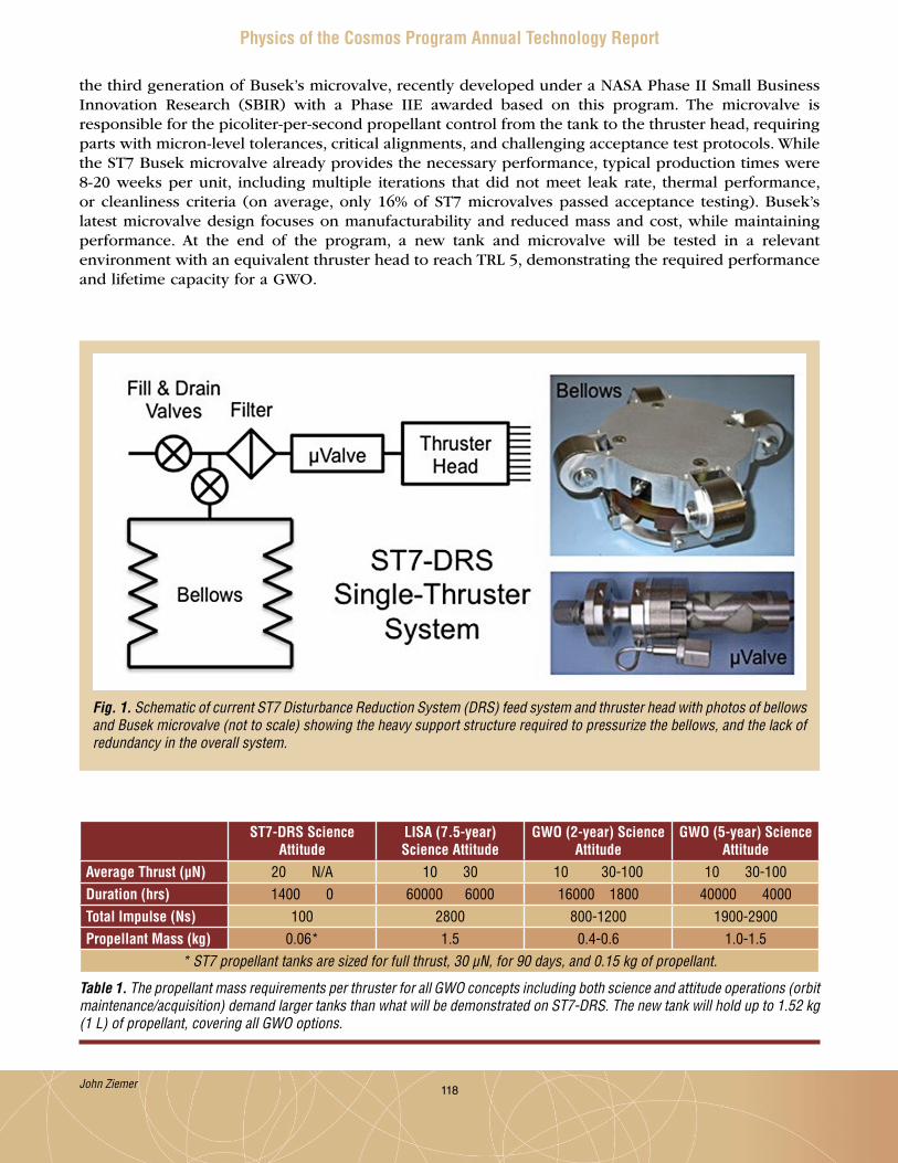
118
Physics of the Cosmos Program Annual Technology Report
the third generation of Busek’s microvalve, recently developed under a NASA Phase II Small Business Innovation Research (SBIR) with a Phase IIE awarded based on this program . The microvalve is responsible for the picoliter-per-second propellant control from the tank to the thruster head, requiring parts with micron-level tolerances, critical alignments, and challenging acceptance test protocols . While the ST7 Busek microvalve already provides the necessary performance, typical production times were 8-20 weeks per unit, including multiple iterations that did not meet leak rate, thermal performance, or cleanliness criteria (on average, only 16% of ST7 microvalves passed acceptance testing) . Busek’s latest microvalve design focuses on manufacturability and reduced mass and cost, while maintaining performance . At the end of the program, a new tank and microvalve will be tested in a relevant environment with an equivalent thruster head to reach TRL 5, demonstrating the required performance and lifetime capacity for a GWO .
Fig. 1. Schematic of current ST7 Disturbance Reduction System (DRS) feed system and thruster head with photos of bellows and Busek microvalve (not to scale) showing the heavy support structure required to pressurize the bellows, and the lack of redundancy in the overall system.
ST7-DRS Science Attitude
LISA (7.5-year) Science Attitude
GWO (2-year) Science Attitude
GWO (5-year) Science Attitude
Average Thrust (µN) 20 N/A 10 30 10 30-100 10 30-100Duration (hrs) 1400 0 60000 6000 16000 1800 40000 4000Total Impulse (Ns) 100 2800 800-1200 1900-2900Propellant Mass (kg) 0.06* 1.5 0.4-0.6 1.0-1.5
* ST7 propellant tanks are sized for full thrust, 30 µN, for 90 days, and 0.15 kg of propellant.
Table 1. The propellant mass requirements per thruster for all GWO concepts including both science and attitude operations (orbit maintenance/acquisition) demand larger tanks than what will be demonstrated on ST7-DRS. The new tank will hold up to 1.52 kg (1 L) of propellant, covering all GWO options.
John Ziemer

119
Physics of the Cosmos Program Annual Technology Report
The new feed system (shown schematically in Fig . 2) will use a more traditional diaphragm tank design (shown in a sectional drawing in Fig . 3) . The thruster cluster mass can be nearly the same as ST7 despite the increased propellant mass . This is achieved through a lightweight torispherical stainless steel (304L) tank design with only 0 .5 mm (20 mil) wall thickness due to the low feed pressures required . The tank will be operated in blow-down mode from 2 Atm to 1 Atm . Although diaphragm tanks have been used extensively in space flight, our tank design is unique in that it uses an ionic liquid, EMI-Im (1-ethyl-3-methylimidazolium bis(trifluoromethylsulfonyl)imide) and compatible, non-magnetic, stainless steel material for the shell and the diaphragm . Standard elastomeric diaphragms used throughout the industry are not compatible with EMI-Im, and Al diaphragms used in some existing tank designs would suffer pitting corrosion . In addition, the torispherical tank design will be easier to clean and dry than bellows, resulting in reduced risk of bubbles, contamination, and clogging in the feed system and thruster head . Compared to scaling up the original ST7 bellows system, the new feed system will realize mass savings of 19 kg per thruster cluster, corresponding to 57 kg mass savings per spacecraft and 171 kg mass savings per three-spacecraft mission .
Fig. 2. Schematic of the new Colloid Microthruster Feed System, including a diaphragm tank developed by JPL that will reduce system mass by more than 50% compared to a scaled-up bellows architecture. The feed system includes four Busek microvalves arranged in a fully redundant configuration with a simple, single-propellant-line interface. Each part will undergo environmental testing and the entire system will be assembled and tested at JPL to reach TRL 5.
John Ziemer
Objectives and MilestonesThe objective of this project is to develop a lightweight (< 2 kg), 5-year-capacity feed system for future GWO colloid-propulsion systems . This will include a new, more reliable microvalve design and a metal diaphragm tank of 1 liter fuel capacity, both to be developed to TRL 5 in this project . In addition to component development, a complete feed system will be assembled and tested, consisting of the propellant tank, two serially mounted valves for redundancy, and other required commercial off the shelf (COTS) feed system components to demonstrate system performance . In addition, we will update ST7 processes including cleaning, propellant loading, and priming, as well as functional, acceptance, and qualification test procedures . The four main project objectives are as follows .

120
Physics of the Cosmos Program Annual Technology Report
1 . Design tank and feed system with a 5-year GWO mission capacity and full redundancy Use standard liquid propulsion feed system principles and practices to design a redundant colloid
microthruster feed system, including interface and environmental requirements . Deliverables are feed system specifications and interface documents . We conducted a peer review of the design with liquid propulsion system experts at the end of FY 2013 .
2 . Design, fabricate, and test the stainless steel diaphragm tank to reach TRL 5 Design and test tank to 1 .25 times Maximum Design Pressure, 5 Atm (note that maximum expected
operating pressure, MEOP, is 2 Atm, providing a large margin) and 1 liter, or 1 .5 kg, fuel capacity with > 99% expulsion efficiency . JPL will guide tank design, and Keystone Engineering Company will manufacture the tank and perform cycle and burst testing . Deliverables are a tank design, one tank in place for destructive testing, and one tank delivered to JPL for integration tests (note that originally both tanks were to be delivered to JPL, but the vendor will now conduct the thermal, burst, and cycle tests on one of the tanks to reduce cost) .
Fig. 3. Cut-away drawing of the new torispherical diaphragm tank designed by Keystone Engineering Company. The tank is constructed of non-magnetic stainless steel with enough volume (approximately 25 cm diameter and 14 cm height) to supply 1 liter (1.5 kg, or five years of operation) of ionic liquid propellant at 1-2 Atm (2 Atm at beginning of mission, 1 Atm at end of mission).
John Ziemer

121
Physics of the Cosmos Program Annual Technology Report
3 . Design, fabricate, and test the microvalves to reach TRL 5 This work will be performed by the microvalve supplier for ST7, Busek Co . Inc ., leveraging experience
gained with that program and the recently completed Phase II SBIR for microvalve development (note that this program is benefiting from an SBIR Phase IIE for microvalve development) . Deliverables include a valve design, two microvalve assemblies (each containing two microvalves plus supporting hardware) for environmental testing at Busek, and system integration with the new propellant tank at JPL .
4 . Integrate and test feed system components This objective includes integration of the tank with a microvalve assembly, including other COTS
feed system components modified for EMI-Im use . To keep testing costs down, no thrusters will be installed . Instead, high precision flow meters developed during the ST7 program will be used as thruster simulators to verify system operation . The setup will be used to develop and demonstrate feed system cleaning procedures, loading procedures, and full dynamic range control at the end of the task .
The following are key task milestones (note that a delay in tank procurement shifted some milestones that were originally in Year 1 to Year 2, but did not change the overall task scope) .
Year 1 (January 2013 to December 2013): Busek placed on contract for microvalve and project support (completed Apr . 2013); Internal Design Review (completed May 2013); Prototype microvalve fabrication and test (completed Jul . 2013); Long-lead propellant tank procurement order submitted to vendor (completed Nov . 2013 – delay of
seven months vs . original plan due to search for new tank vendor; original vendor was acquired by another company that did not respond to request for proposal/quote); and
Feed system component-level and system-level requirements (completed Dec . 2013) .
Year 2 (January 2014 to December 2014): Ground support equipment (GSE) design and part selection (completed Jan . 2014); Feed system COTS component down-select (completed Feb . 2014); Review of feed system and GSE design, test, and integration processes (completed Mar . 2014); Development model microvalve and volume compensator fabrication (completed Apr . 2014); Design Concept Review at Keystone Engineering facility (completed May 2014); Procurements placed for all GSE and COTS hardware (completed Jun . 2014);• Release final procedures based on Process Peer Review (Jul . 2014);• Microvalve environmental testing complete (Aug . 2014);• Microvalve development model delivery to JPL (Aug . 2014);• Supporting feed system components delivery to JPL (Aug . 2014);• GSE fabrication complete (Aug . 2014);• Propellant drying complete (Sep . 2014);• Tank cycle and proof-testing complete (Sep . 2014);• Tank delivery to JPL (Sep . 2014);• Component-level environmental test results review (Oct . 2014);• Full integration of feed system components (Oct . 2014);• Feed System functional tests complete (Nov . 2014); and• Final test results review (Dec . 2014) .
Note that some delays in microvalve and tank fabrication have pushed hardware delivery milestones back by one or two months . Full system integration will now occur in October 2014; however, since all environmental testing is occurring at vendor locations prior to delivery, the full task should still be completed by the end of December 2014, as originally planned .
John Ziemer

122
Physics of the Cosmos Program Annual Technology Report
Progress and AccomplishmentsThe Colloid Microthruster Propellant Feed System task started under contract at JPL in January 2013 . The first six months focused on developing requirements, letting contracts for the tank, which incurred long delays due to a no-bid response from our original vendor, microvalve procurements, and developing more detailed plans for testing to demonstrate TRL 5, all of which were described in last year’s annual report . In the past year (since June 2013), we have brought on a new vendor for the diaphragm tank, Keystone Engineering Company, successfully completed environmental testing of the Busek microvalve, developed designs for all GSE, and procured all components for the GSE and supporting commercial feed system components (latch valve and fill/drain valves) . The following details progress and major accomplishments during the first six months of the project, broken down by objective .
1. Design tank and feed system with a 5-year GWO mission capacity and full redundancySpecifications and baseline requirements for the critical parts of the feed system, the tank and microvalve, were completed three months after the project started, in March 2013 . Based on these specifications, procurement of the microvalves from Busek Co ., Inc . was initiated in April 2013, with an expected completion date one year later . Some delays for microvalve part manufacture and requirement flow-down from the actual tank design required a no-cost extension for Busek, which is now scheduled to complete delivery in August 2014 . In addition, Busek was awarded an SBIR Phase IIE that gave matching funds to develop additional hardware parts and modifications necessary to integrate the microvalve into the new feed system . This work is described in more detail under Objective 3 .
Initiation of diaphragm tank procurement had even more schedule and budget difficulties, when the original vendor described in the proposal, AMPAC, was acquired by another company, Moog, Inc ., which decided not to participate in this task . After months of searching, Keystone Engineering Company, which has developed many prototype and one-off tanks, indicated they would be interested in developing the new tank for our task . While the cost was slightly higher than the previous company’s estimate, the schedule was shorter, which allowed the task to continue in the same two-year time frame . In addition, both Busek and Keystone agreed to perform environmental testing at their facilities which, together with a reduction in management and systems engineering at JPL, covered the additional tank contract cost . This work is described in further detail in Objective 2 .
This objective also includes the systems engineering for developing supporting hardware specifications, GSE design, and part procurement . The GSE and feed system schematics are shown in Fig . 4 . All additional parts, including commercial flight-like components in the feed system, have been procured . The feed system fill/drain valves will be supplied by Moog, Inc . with flight heritage traceability, except for the valve seat O-ring material, replaced for propellant compatibility . The feed system latch valves will be supplied by Vacco, Inc ., as Engineering Model (EM) components, with flight heritage to similar qualified components . We chose to use “flight-like” parts with traceable heritage and testing to qualified hardware instead of actual certified flight hardware to reduce cost .
2. Design, fabricate, and test stainless steel diaphragm tank to reach TRL 5The diaphragm tank will be designed, fabricated, and tested by Keystone Engineering Company . It will be made of non-magnetic stainless steel (304L) and have a total volume of just over 2 liters, half of which will be filled with EMI-Im propellant . The tank will have a maximum design pressure (MDP) of 4 Atm, approximately double the pressure needed to achieve the full flow rate through the feed system based on CMNT system experience . The actual tank pressure will be set after testing, allowing for significant margin and safety while still achieving our mass target of 1 kg . Expulsion efficiency shall be greater than 99%, and qualification testing of the tank will include 25 expulsion cycles . However, expulsion efficiency may be reduced to 98% to provide additional cycles . Acceptance, qualification, expulsion, and burst-test requirements have been documented in a detailed specification . Keystone successfully passed
John Ziemer
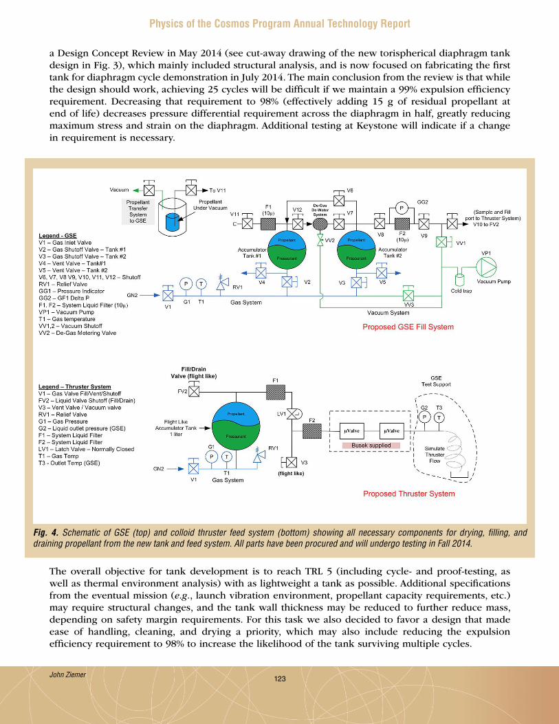
123
Physics of the Cosmos Program Annual Technology Report
a Design Concept Review in May 2014 (see cut-away drawing of the new torispherical diaphragm tank design in Fig . 3), which mainly included structural analysis, and is now focused on fabricating the first tank for diaphragm cycle demonstration in July 2014 . The main conclusion from the review is that while the design should work, achieving 25 cycles will be difficult if we maintain a 99% expulsion efficiency requirement . Decreasing that requirement to 98% (effectively adding 15 g of residual propellant at end of life) decreases pressure differential requirement across the diaphragm in half, greatly reducing maximum stress and strain on the diaphragm . Additional testing at Keystone will indicate if a change in requirement is necessary .
Fig. 4. Schematic of GSE (top) and colloid thruster feed system (bottom) showing all necessary components for drying, filling, and draining propellant from the new tank and feed system. All parts have been procured and will undergo testing in Fall 2014.
John Ziemer
The overall objective for tank development is to reach TRL 5 (including cycle- and proof-testing, as well as thermal environment analysis) with as lightweight a tank as possible . Additional specifications from the eventual mission (e.g., launch vibration environment, propellant capacity requirements, etc .) may require structural changes, and the tank wall thickness may be reduced to further reduce mass, depending on safety margin requirements . For this task we also decided to favor a design that made ease of handling, cleaning, and drying a priority, which may also include reducing the expulsion efficiency requirement to 98% to increase the likelihood of the tank surviving multiple cycles .
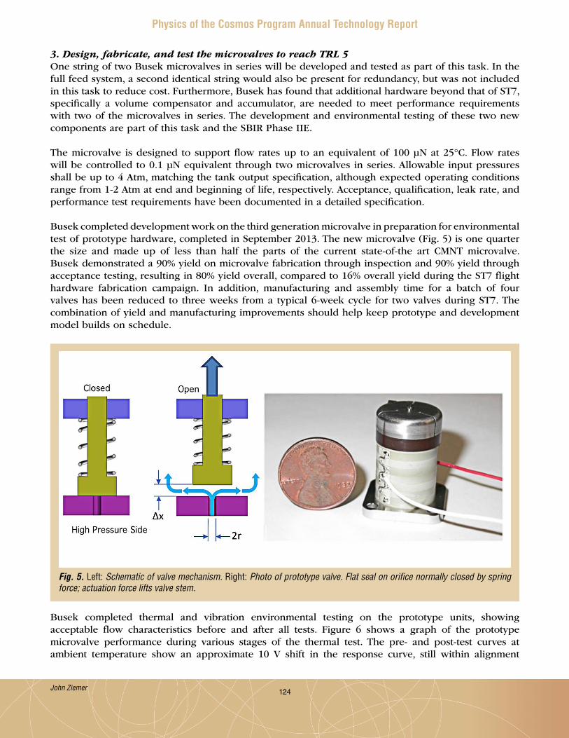
124
Physics of the Cosmos Program Annual Technology Report
3. Design, fabricate, and test the microvalves to reach TRL 5One string of two Busek microvalves in series will be developed and tested as part of this task . In the full feed system, a second identical string would also be present for redundancy, but was not included in this task to reduce cost . Furthermore, Busek has found that additional hardware beyond that of ST7, specifically a volume compensator and accumulator, are needed to meet performance requirements with two of the microvalves in series . The development and environmental testing of these two new components are part of this task and the SBIR Phase IIE .
The microvalve is designed to support flow rates up to an equivalent of 100 µN at 25°C . Flow rates will be controlled to 0 .1 µN equivalent through two microvalves in series . Allowable input pressures shall be up to 4 Atm, matching the tank output specification, although expected operating conditions range from 1-2 Atm at end and beginning of life, respectively . Acceptance, qualification, leak rate, and performance test requirements have been documented in a detailed specification .
Busek completed development work on the third generation microvalve in preparation for environmental test of prototype hardware, completed in September 2013 . The new microvalve (Fig . 5) is one quarter the size and made up of less than half the parts of the current state-of-the art CMNT microvalve . Busek demonstrated a 90% yield on microvalve fabrication through inspection and 90% yield through acceptance testing, resulting in 80% yield overall, compared to 16% overall yield during the ST7 flight hardware fabrication campaign . In addition, manufacturing and assembly time for a batch of four valves has been reduced to three weeks from a typical 6-week cycle for two valves during ST7 . The combination of yield and manufacturing improvements should help keep prototype and development model builds on schedule .
Fig. 5. Left: Schematic of valve mechanism. Right: Photo of prototype valve. Flat seal on orifice normally closed by spring force; actuation force lifts valve stem.
Busek completed thermal and vibration environmental testing on the prototype units, showing acceptable flow characteristics before and after all tests . Figure 6 shows a graph of the prototype microvalve performance during various stages of the thermal test . The pre- and post-test curves at ambient temperature show an approximate 10 V shift in the response curve, still within alignment
John Ziemer

125
Physics of the Cosmos Program Annual Technology Report
requirements of ≤ 2 µm . However, vibration testing of a separate prototype microvalve also showed a 15 V shift before and after testing, indicating inadequate staking of critical alignment components . The next set of microvalves, to be delivered to JPL, will include an additional staking step to help reduce this shift .
Fig. 6. Graph of prototype microvalve flow rate vs. driving voltage before and after various thermal conditions. The pre- and post-test curves at ambient temperature show an approximate 10 V shift in the response curve, still within alignment requirements. The next set of microvalves will include an additional staking step to help reduce this shift.
Busek is also developing a volume compensator to ensure propellant is removed from downstream components (mainly the thruster head) prior to closing the microvalves, and a passive accumulator to ensure high-pressure spikes that could potentially damage other components do not propagate through the feed system . These two new components will also be delivered and tested as part of this task .
4. Integrate and test feed system componentsThis objective is the focus of the last half of the second year of the project once hardware is delivered . While some planning and procedure development functions have occurred during this time, no results will be available until Fall 2014, after all components are delivered .
Path ForwardWork on the Colloid Microthruster Feed System will continue as planned, with the major near-term focus on developing test procedures, assembling GSE as parts arrive, drying propellant, and preparing for main tank and microvalve components delivery . The microvalves will arrive at JPL in August 2014, with the tank arriving in September 2014 . Once the hardware is in-house, integration and test will begin at JPL, with project completion expected in December 2014 .
John Ziemer

126
Physics of the Cosmos Program Annual Technology Report
References[1] NASA Physics of the Cosmos Program, “Program Annual Technology Report,” (November 2011) .[2] Ziemer et al., “Colloid Micro-Newton Thrusters for the Space Technology 7 Mission,” IEEE Aerospace
Conference, Big Sky, Montana (2010) .[3] ANSI/AIAA S-080-1998, “Space Systems-Metallic Pressure Vessels, Pressurized Structures, and
Pressure Components” (September 13, 1999) .
For additional information, contact John Ziemer: [email protected]
John Ziemer

127
Physics of the Cosmos Program Annual Technology Report
Gravitational-Wave Mission Phasemeter Technology Development Prepared by: William Klipstein (PI; JPL, Caltech); Jeff Dickson, Glenn de Vine, Kirk McKenzie, Robert Spero, Andrew Sutton, and Brent Ware (JPL)
This SAT project was funded very recently, thus this PI report only outlines project objectives and plans. A full report will be included in next year’s PATR.
SummaryThe proposed work will advance the Technology Readiness Level (TRL) of our phase measurement electronics, and demonstrate their performance in an upgraded interferometer-system level test-bed; the test-bed will provide signals representative of gravitational wave missions, such as the Laser Interferometer Space Antenna (LISA) . Our technology development effort starts with the photons-to-bits Phase Measurement System (interferometer readout electronics) demonstrated as a system to TRL 4 in an interferometer test-bed providing signals representative of a LISA-like mission . Some components, most notably the digital phasemeter board, have been developed beyond TRL 4 .
For this task, as shown in Fig . 1, we will (1) replace the commercial single-element photo-receivers used in our test-bed with our custom quadrant photo-receivers meeting the LISA requirement; (2) design and build a second-generation analog signal-conditioning chain, including analog-to-digital converters, raising TRL from 4 to 5; (3) integrate the analog signal path to our TRL 6 phasemeter digital board; and (4) test in a signal environment that adds low light levels to increase signal fidelity . This two-year effort will advance the TRL of the Phase Measurement System from 4 to 5, based on the significant increase in system-level hardware fidelity and the greater signal test-environment fidelity .
LISA-like gravitational-wave mission concepts rely on heterodyne laser interferometry to measure picometer level fluctuations in the separation between three widely separated spacecraft . The transmit and receive beams from a spacecraft pair are mixed optically (interfered) on a beam combiner, resulting in a detected signal varying sinusoidally at the frequency difference between the local transmit laser and the laser received from the distant spacecraft . Picometer-level displacement sensitivity requires microcycle-level precision on the phase difference compared to the micron-scale wavelength of the laser light .
Since 2005, we have been developing phase measurement systems to validate and support the “photons to bits” interferometer signal readout based on the LISA mission parameters as described in the LISA Technology Development Plan . Future variants on gravitational-wave missions all (except for the less mature atom interferometer concepts) involve laser interferometry between widely separated spacecraft and will rely on a LISA-like phasemeter and Time-Delay Interferometry to mitigate the impact of laser frequency noise on mission performance .
William Klipstein
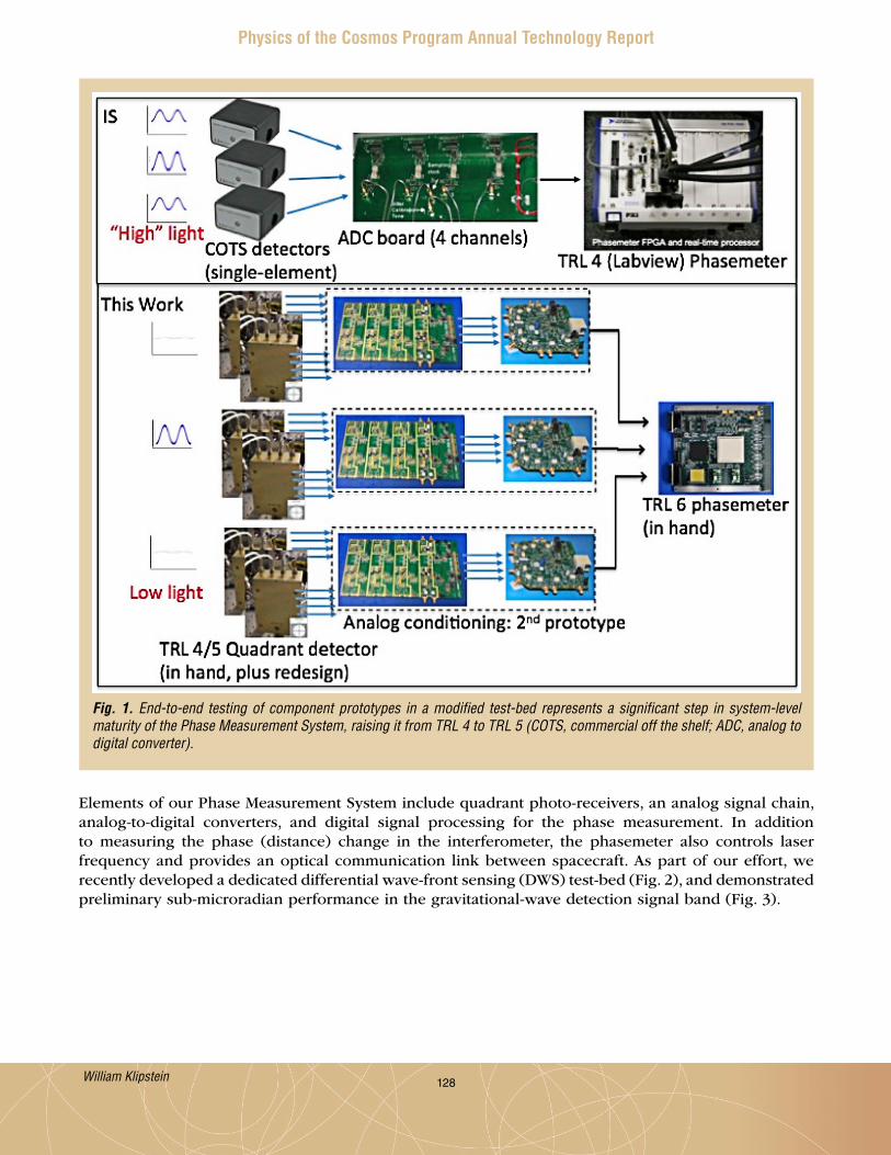
128
Physics of the Cosmos Program Annual Technology Report
Fig. 1. End-to-end testing of component prototypes in a modified test-bed represents a significant step in system-level maturity of the Phase Measurement System, raising it from TRL 4 to TRL 5 (COTS, commercial off the shelf; ADC, analog to digital converter).
Elements of our Phase Measurement System include quadrant photo-receivers, an analog signal chain, analog-to-digital converters, and digital signal processing for the phase measurement . In addition to measuring the phase (distance) change in the interferometer, the phasemeter also controls laser frequency and provides an optical communication link between spacecraft . As part of our effort, we recently developed a dedicated differential wave-front sensing (DWS) test-bed (Fig . 2), and demonstrated preliminary sub-microradian performance in the gravitational-wave detection signal band (Fig . 3) .
William Klipstein
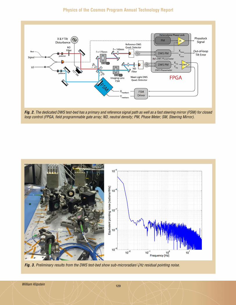
129
Physics of the Cosmos Program Annual Technology Report
Fig. 2. The dedicated DWS test-bed has a primary and reference signal path as well as a fast steering mirror (FSM) for closed loop control (FPGA, field programmable gate array; ND, neutral density; PM, Phase Meter; SM, Steering Mirror).
Fig. 3. Preliminary results from the DWS test-bed show sub-microradian/√Hz residual pointing noise.
William Klipstein
130
Physics of the Cosmos Program Annual Technology Report
Objectives and MilestonesThe objective of this project is to advance our Phase Measurement System from TRL 4 to 5, through significant system-level hardware fidelity increase and greater fidelity of signal test environment by adding low light levels .
Key project milestones:
1 . Design 2nd generation analog signal chain (November 2014) .2 . Build 2nd generation analog signal chain (February 2015) .3 . Demonstrate wave-front sensing (September 2015) .4 . Implement quadrant photo-receivers in existing test-bed (December 2015) .
For additional information, contact William Klipstein: [email protected]
William Klipstein

131
Physics of the Cosmos Program Annual Technology Report
Demonstration of a TRL 5 Laser System for eLISAPrepared by: Jordan Camp (NASA/GSFC)
This SAT project was funded very recently, thus this PI report only outlines project objectives and plans. A full report will be included in next year’s PATR.
SummaryThe evolved Laser Interferometer Space Antenna (eLISA) gravitational-wave space mission will be proposed for the European Space Agency (ESA) L2 launch opportunity, and NASA intends to contribute instruments to the mission . eLISA’s eventual flight will open a spectacular new window on the universe, using gravitational waves to reveal the physics and astronomy associated with the merger of massive black hole systems . The backbone of eLISA is a highly stable laser of ~1 .2 W power, which enables the picometer interferometry necessary to record the passage of a gravitational wave; such a laser is listed as a top priority of the Physics of the Cosmos Program Analysis Group (PhysPAG) technology roadmap . eLISA is now under technology development in Europe, and the Europeans have expressed interest in the laser system as a possible contribution from the US . This work is intended to mature the technology, demonstrating a Technology Readiness Level (TRL) of 5 for the full eLISA laser system by 2016, allowing maximum flexibility for mission implementation . After several years of trade studies and investments in numerous laser technologies, we selected a state-of-the-art master-oscillator power-amplifier approach . The oscillator is a compact, low-mass, low-noise, semiconductor External Cavity Laser (ECL), sufficiently robust for operation in space – the ECL was recently adopted for a precision metrology application on the International Space Station . In addition, our custom-designed fiber amplifier is now close to meeting the full range of eLISA noise and power requirements . Our plan involves two steps to demonstrate a TRL 5 eLISA laser system . First, incorporate the understanding gained from our lab R&D prototype noise and reliability testing into a rebuilt oscillator and amplifier . Second, with the oscillator and amplifier development complete, do a full system test of the laser, using control systems to achieve the required laser power, frequency, intensity, and differential phase noise .
Objectives and MilestonesThe objective of this project is to demonstrate a TRL 5 ECL-based eLISA laser system, achieving the required laser power, frequency, intensity, and differential phase noise .
Key project milestones:
1 . Rebuild and test 1 .5 W laser amplifier (Aug . 2014) .2 . Preliminary laser system test with Non-Planar Ring Oscillator (NPRO) (Dec . 2014) .3 . Noise optimization of ECL optical cavity (Dec . 2014) .4 . Preliminary laser system test with ECL (Mar . 2015) .5 . Noise optimization of ECL gain chip (Aug . 2015) .6 . ECL reliability tests ( Jan . 2016) .7 . Full laser system noise testing (Jan . 2016) .8 . Full laser system reliability testing (Mar . 2016) .
For additional information, contact Jordan Camp: [email protected]
Jordan Camp

132
Physics of the Cosmos Program Annual Technology Report
Planar Antenna-Coupled Superconducting Detectors for CMB PolarimetryPrepared by: James J. Bock (JPL, Caltech)
SummaryWe are developing advanced, antenna-coupled superconducting detector array technology for the NASA Inflation Probe, a future satellite dedicated to comprehensive measurements of Cosmic Microwave Background (CMB) polarization . This Strategic Astrophysics Technology (SAT) program, in support of NASA’s Physics of the Cosmos (PCOS) technology development, will extend the demonstrated frequency range of antennas down to 40 GHz and up to 250 GHz, and develop dual-band antennas that offer a higher density of detectors, a valuable resource in a 100 mK space-borne focal plane . We will carry out a systematic study of polarized beam-matching in representative optical systems . Based on our work to date on cosmic-ray interactions in bolometers, we will test particle hits in a full antenna-coupled bolometer array with a Si frame designed for immunity to cosmic rays . Finally, we will characterize 1/f noise stability in a microwave resonator Superconducting QUantum Interference Device (SQUID) multiplexing system that offers significant system resource savings compared to current time-domain or frequency-domain multiplexing . Our program builds on a previous award, closely coupled with ground-based and sub-orbital CMB polarization experiments using antenna-coupled superconducting transition edge sensor (TES) bolometer arrays . The developments for space are informed by our experience developing an earlier generation of bolometers for the European Space Agency (ESA) Planck satellite .
Antenna-coupled detectors have the requisite attributes – sensitivity, frequency coverage, and control of systematic errors – called for in community studies of space-borne CMB polarization experiments . The arrays provide integral beam-formation, spectral band definition, and polarization analysis; and scale to operate over the wide frequency range of 30 - 300 GHz, required to remove galactic foregrounds at near-background-limited sensitivity with rapid response and 1/f noise stability .
This two-year program began in October 2013 and includes Jeff Filippini, Chao-Lin Kuo, Martin Lueker, Roger O’Brient, Anthony Turner, and Alexis Weber . Most notably, this year the antenna-coupled bolometer array technology being furthered through this program was used to make new measurements of CMB polarization on degree angular scales with the Background Imaging of Cosmic Extragalactic Polarization 2 (BICEP2) ground-based instrument . In March of 2014, BICEP2 reported detection of B-mode polarization at 150 GHz with high statistical significance and excellent control of systematic errors, demonstrating antenna-coupled bolometer arrays are suitable for demanding CMB polarization measurements .
BackgroundThe importance of CMB polarization research has been recognized in national reports including the 1999 National Academy Report, the 2001 Decadal Survey, and the 2003 NRC report “Connecting Quarks with the Cosmos .” In 2005, the Task Force on Cosmic Microwave Background Research stated that its first technology recommendation was “technology development leading to receivers that contain a thousand or more polarization sensitive detectors,” and that “highest priority needs to be given to the development of bolometer-based polarization sensitive receivers.” The 2010 Decadal Survey, New Worlds, New Horizons in Astronomy and Astrophysics (NWNH) endorsed a CMB technology program of $60 – $200M as its second-ranked medium initiative for space . In addition, NWNH suggests that this amount could be increased to $200M following a mid-decade review of the state of CMB polarization
James Bock

133
Physics of the Cosmos Program Annual Technology Report
measurements . The CMB Technology Roadmap ranked detector arrays as its highest priority of CMB technologies, recommending a program that takes maximum advantage of operating the arrays in sub-orbital and ground-based CMB polarization experiments .
The Inflation Probe will measure CMB polarization over the entire sky to cosmological and astrophysical limits . The CMB is thought to carry a B-mode polarization signal imparted by a gravitational-wave background produced by the Inflationary expansion ~10-32 sec . after the Big Bang singularity . The Inflationary polarization signal is sensitive to the energy scale and shape of the Inflationary potential, and can be clearly distinguished from polarization produced by matter density variations due to its distinctive B-mode spatial signature . A detection of the Inflationary polarization signal would do more than just confirm Inflation - the amplitude of gravitational waves depends on the model and energy scale of Inflation, so detection would distinguish between models and constrain the physical process underlying Inflation . Such a measurement has profound implications for cosmology, and bears on the current frontiers of fundamental physics – the union of general relativity and quantum mechanics, string theory, and the highest accessible energies .
The Inflation Probe will also map the CMB polarization pattern produced by gravitational lensing . Intervening matter between us and the surface of last scattering slightly distorts the background CMB polarization, imparting a B-mode signal that peaks at arc-minute angular scales and probes the evolution of large-scale structure, which is sensitive to neutrino mass and dark energy . The CMB lensing signal is related to the projected gravitational potential of this matter, and provides a powerful combination with dark-energy surveys such as baryon acoustic oscillations and weak lensing .
The most recent definition study of the Inflation Probe in 2008/9 developed the basis for space-borne CMB polarization measurements . The study drew wide participation across the CMB community, and led to a series of consensus papers on the scientific and technical case . High-sensitivity detector arrays operating over a wide range of frequencies (30 – 300 GHz) to accurately measure and remove polarized galactic foregrounds were identified as the key technology gap . This detector system must demonstrate extreme 1/f noise stability, forward-beam definition with stray-light immunity, RF and magnetic shielding, excellent spectral band and time constant matching, and cosmic-ray insusceptibility . Alternate approaches have been proposed including the ESA Polarized Radiation Imaging and Spectroscopy Mission (PRISM), and NASA and Japanese Aerospace Exploration Agency (JAXA) concepts based on small (30 and 60 cm) telescope apertures with smaller detector counts but similar detector performance requirements .
These antenna-coupled superconducting detector arrays (Fig . 1) are a scalable planar focal plane architecture that coherently sums an array of individual slot antennas with a microstrip feed network, controlling the phase and E-field amplitude distributed to each slot . The planar antenna enables customized shaping of the detector beam pattern for controlling detector illumination on critical optical surfaces . The antenna operates in two polarizations – an array of horizontal slots couples to one detector, and an interleaved array of vertical slots couples to another . The spectral band is defined by a 3-pole RF microstrip filter . Power from the antenna is deposited in a meandered Au resistor on a thermally isolated bolometer, detected by a Ti/Al TES sensor and read out by a multiplexed SQUID current amplifier .
Planar antennas are entirely lithographed and avoid coupling optics such as feedhorns or hyper-hemispherical lenses, ideal for a low-mass 100 mK focal plane for space . The devices can cover the wide range of frequencies by scaling the antenna with wavelength and keeping the detector element essentially unchanged . The antennas demonstrate excellent polarization properties and the lithographed filters provide reproducible control of the spectral band . The Ti TES sensors give predictable noise properties and low-frequency noise stability .
James Bock

134
Physics of the Cosmos Program Annual Technology Report
Detection of B-Mode Polarization with BICEP2The BICEP2 instrument fielded a focal plane array of 512 polarization-sensitive, antenna-coupled TES bolometers for three observing seasons at the South Pole, surveying ~2% of the sky to carry out a deep search for the Inflationary gravitational-wave B-mode polarization signal . The antenna-coupled focal plane array demonstrated an on-sky sensitivity of 15 .8 µKcmb √s, a 10-fold improvement in mapping speed over the BICEP1 instrument using 96 individual semi-conducting bolometers . In three years of observations at 150 GHz, BICEP2 produced a sensitive polarization map and separated out a prominent
Fig. 1. Focal plane array of antenna-coupled TES bolometers (circular structure under viewing microscope). The focal plane uses four detector wafers operating 64 dual-polarization antennas at a frequency of 150 GHz, with a total of 512 detectors. The array’s SQUID readouts, located at the upper and lower edges, consist of sixteen 32-channel devices. The antennas provide beam-formation, polarization analysis, spectral filtering, and photon detection. The microscope, as shown in monitor, views a region of one antenna and a TES detector. The antennas consist of an array of vertical and horizontal slots, combined coherently with a feed network that can be designed for beam formation.
James Bock

135
Physics of the Cosmos Program Annual Technology Report
B-mode polarization pattern (Fig . 2) . The power spectrum of the BICEP2 map (Fig . 3, left panel) is inconsistent with standard Lambda Cold Dark Matter (ΛCDM) cosmological theory at high statistical significance . The signal also cannot be explained by systematic errors, which have been thoroughly characterized and tested with a battery of difference tests . The advance of the BICEP2 measurement can be appreciated by comparing the significantly deeper sensitivity with all current and previous attempts (Fig . 3, right panel) . BICEP2 demonstrates the performance of antenna-coupled bolometer array technology in a scientific application that is representative of the polarization measurements to be performed on the NASA Inflation Probe .
Fig. 2. B-mode polarization pattern measured by the BICEP2 instrument at 150 GHz. The blue and red coloration indicates the (positive and negative) B-mode amplitude, corresponding to clockwise and counter-clockwise spiral polarization patterns, respectively. The measurement was obtained in three years of observations, using a focal plane array of planar antenna-coupled bolometers similar in design to devices being developed through this SAT program.
Scientifically, the BICEP2 B-mode polarization signal could be explained by an Inflationary gravitational-wave signal with a high tensor to scalar ratio . However, galactic foreground polarized synchrotron and dust emission must be carefully accounted for . The level of galactic synchrotron emission can be constrained to a negligible level by correlating with low-frequency Wilkinson Microwave Anisotropy Probe (WMAP) data . Polarized dust emission is more difficult to constrain, given the current lack of public data . However, an all-dust interpretation is disfavored based on the morphology and spectrum of the BICEP data, and the lack of apparent correlation with pre-existing dust models . In the coming months, multi-frequency data, including antenna-coupled bolometers in the Keck Array experiment operating at 95 GHz, and data from the Planck satellite, will make a precise determination of the level of galactic and cosmological signal . These results bear directly on the scientific goals of the Inflation Probe and the sensitivity and frequency coverage needed for discriminating foregrounds in a future space-borne measurement .
James Bock
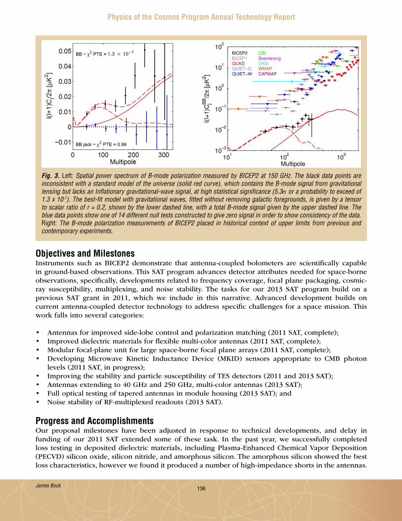
136
Physics of the Cosmos Program Annual Technology Report
Objectives and MilestonesInstruments such as BICEP2 demonstrate that antenna-coupled bolometers are scientifically capable in ground-based observations . This SAT program advances detector attributes needed for space-borne observations, specifically, developments related to frequency coverage, focal plane packaging, cosmic-ray susceptibility, multiplexing, and noise stability . The tasks for our 2013 SAT program build on a previous SAT grant in 2011, which we include in this narrative . Advanced development builds on current antenna-coupled detector technology to address specific challenges for a space mission . This work falls into several categories:
• Antennas for improved side-lobe control and polarization matching (2011 SAT, complete);• Improved dielectric materials for flexible multi-color antennas (2011 SAT, complete);• Modular focal-plane unit for large space-borne focal plane arrays (2011 SAT, complete);• Developing Microwave Kinetic Inductance Device (MKID) sensors appropriate to CMB photon
levels (2011 SAT, in progress);• Improving the stability and particle susceptibility of TES detectors (2011 and 2013 SAT);• Antennas extending to 40 GHz and 250 GHz, multi-color antennas (2013 SAT);• Full optical testing of tapered antennas in module housing (2013 SAT); and• Noise stability of RF-multiplexed readouts (2013 SAT) .
Progress and AccomplishmentsOur proposal milestones have been adjusted in response to technical developments, and delay in funding of our 2011 SAT extended some of these task . In the past year, we successfully completed loss testing in deposited dielectric materials, including Plasma-Enhanced Chemical Vapor Deposition (PECVD) silicon oxide, silicon nitride, and amorphous silicon . The amorphous silicon showed the best loss characteristics, however we found it produced a number of high-impedance shorts in the antennas .
Fig. 3. Left: Spatial power spectrum of B-mode polarization measured by BICEP2 at 150 GHz. The black data points are inconsistent with a standard model of the universe (solid red curve), which contains the B-mode signal from gravitational lensing but lacks an Inflationary gravitational-wave signal, at high statistical significance (5.3σ or a probability to exceed of 1.3 x 10⁻⁷). The best-fit model with gravitational waves, fitted without removing galactic foregrounds, is given by a tensor to scalar ratio of r = 0.2, shown by the lower dashed line, with a total B-mode signal given by the upper dashed line. The blue data points show one of 14 different null tests constructed to give zero signal in order to show consistency of the data. Right: The B-mode polarization measurements of BICEP2 placed in historical context of upper limits from previous and contemporary experiments.
James Bock

137
Physics of the Cosmos Program Annual Technology Report
We have been developing a modular focal-plane assembly suited to the construction of the large focal-plane arrays needed for space . This modular construction enables testing and qualification of individual sub-arrays that include detectors and readout amplifiers, complete with integral magnetic shielding . Our module design was developed for 95 GHz and passed thermal and mechanical tests . Recent efforts have focused on improving the magnetic shielding and optical properties . We tested the magnetic shielding of our first design, and re-engineered the enclosure to improve performance . The new design was tested in both aluminum and niobium, and we found the niobium design demonstrated better shielding at audio frequencies . The optical properties of the module are generally satisfactory, but we have seen some distortion of antenna beams along the frame of the housing, which might be improved by a new corrugation design .
We also made progress on extending antenna operation to 40 GHz and 250 GHz . We developed a 220 GHz focal plane array, which was optically tested, showing generally satisfactory performance in optical efficiency, spectral bandpass, and polarized beam matching (Fig . 4) . The 250 GHz design, intended for ground-based and sub-orbital measurements, and avoiding the 230 GHz CO 2-1 line, will be a minor adaptation of the 220 GHz design . We plan to work on the design of a dual-color 220/270 GHz antenna . This development is guided by spectral tests of several devices in fabrication, including a notch filter and a 220 GHz antenna using silicon nitride . We also plan optical tests of a lightly tapered antenna housed in a focal plane module in a fully representative optical system to measure far-field beam properties . We have already carried out a first preliminary test with encouraging results (Fig . 5) .
Fig. 4. Left: Spectral response for a new 220 GHz antenna-coupled TES bolometer array, giving the desired bandwidth and center frequency. Right: The system optical efficiency of the antenna-coupled devices plus window and blocking filters is 30-35%, comparable to the efficiency achieved in arrays operating at 95 and 150 GHz.
Our first tests on particle susceptibility used TES detectors, read through the time-domain SQUID multiplexer, to investigate effects on the readout . Based on analysis of Planck flight data, which shows that the dominant cosmic-ray susceptibility in these bolometers in a space environment was hits in the Si device frame, we engineered a modified Planck bolometer with a large PdAu heat capacity and improved conductivity to the surrounding housing though gold wire bonds . The devices have been fabricated and await testing at 100 mK in a particle beam facility in France . While these individual device tests are proceeding, the upcoming Spider balloon experiment will provide a representative test of cosmic-ray interactions with the antenna-coupled TES bolometers .
James Bock

138
Physics of the Cosmos Program Annual Technology Report
Our work on antenna-coupled Kinetic Inductance Devices (KIDs) has the goal of improving the Noise Equivalent Power (NEP) to obtain photon-noise-limited sensitivity under CMB loadings in a design that is not susceptible to direct absorption of mm-wave light . To reduce NEP, we use KIDs made of titanium nitride – the high resistivity of TiN yields a very large penetration depth and thus kinetic inductance much larger than the geometrical inductance, providing greatly increased responsivity via the large kinetic inductance fraction and reduced resonance frequency . To eliminate direct absorption, the inductor is shielded by a ground plane and the capacitor has a parallel-plate geometry .
A significant design challenge in the use of TiN in an antenna-coupled architecture is the coupling of mm-wave power from the low-impedance microstrip (tens of Ω impedance) to high-resistivity TiN (100 times more resistive than the Al used in CPW/IDC (coplanar waveguide/interdigitated capacitor) KIDs or the Au used in our TES-based devices . Figure 6 shows our design, which achieves 80% absorption efficiency over a wide bandwidth at 150 GHz . The mm-wave coupling can be adjusted with distance along the structure so that the dissipated mm-wave power density is fairly uniform . The design is adaptable to a wide range of frequencies from 90 to 420 GHz . The titanium nitride inductor resides above the microstrip ground plane, only 800 nm away, to reduce stray coupling . The ground plane acts as a mm-wave short circuit from the perspective of an incoming wave, preventing absorption of mm-wave power directly in the inductor .
Fig. 5. Beam maps from 95 GHz antenna-coupled TES bolometers housed in a modular focal plane assembly. The antennas for this test were lightly tapered and measured with a representative optical system with refracting lenses. The beams are measured in the far-field of the full optical system. The left two beams are responses to vertical and horizontal polarizations, the right figure shows the difference beam. The difference beam shows a ~4% polarization mismatch, however the difference is dominated by out-of-band coupling to the detector island. Future tests will reduce this out-of-band coupling so the level of leakage here is an upper limit on beam mismatch.
James Bock

139
Physics of the Cosmos Program Annual Technology Report
The TLS noise of this design is determined by the silicon layer used in the parallel-plate capacitor . Using hydrogenated amorphous silicon, whose TLS noise has been measured to be low, we can reach photon noise-limited sensitivity at 90 and 150 GHz; the TLS noise degrades total NEP by only 10% . The expected NET
CMB is 40-50 µK
CMB √s from a space-borne platform, comparable to TES
bolometer sensitivities .
Path ForwardAs shown in Table 1, we have carried out successive tests of dielectric materials, and find that silicon oxide and silicon nitride are suitable for frequency coverage up to 300 GHz . The focal plane module has been successively tested, and further magnetic shielding would be desirable . We will test an improvement using a high-mu sheet placed under the SQUIDs inside the superconducting shield . The antennas are being scaled down to 40 GHz and up to 250 GHz to span the frequencies needed for foreground monitoring . The 250 GHz design is informed by our recent tests of a 220 GHz array . A dual-color design will be developed over the summer of 2014 . The focal plane module antennas will be fully tested in a representative optical system to measure beam characteristics, and we will test new corrugation designs on the frame to further reduce interactions between edge antennas and the housing . We will also test
Fig. 6. Design of TiN KID and mm-wave microstrip-to-KID coupler, and simulated coupler performance. The microstrip from the antenna (red) enters from the left in the top diagram and encounters a 50/50 power splitter. Half the power is delayed by λ/2 so a mm-wave voltage appears between corresponding points on the two microstrip branches. This mm-wave voltage is applied across the TiN film (green) and drives a mm-wave current there. Capacitors between the top layer of the microstrip and the TiN film (cross section, lower left) control the strength of the coupling, ensuring it is weak enough that the impedance of the microstrip is unaffected, strong enough that the incident power is absorbed, and can be varied (by increasing capacitor area) with length along the structure so that the power absorption is almost uniform. The lower right diagram shows the entire KID structure, including the mm-wave coupler in the middle (green), the KID capacitor (red, large rectangles at top) and the readout coupling capacitor and readout feed-line (at the bottom, red). The large KID capacitor uses hydrogenated amorphous silicon to render TLS (Two-Level System) noise subdominant. The same dielectric is used in the microstrip carrying the mm-wave power.
James Bock
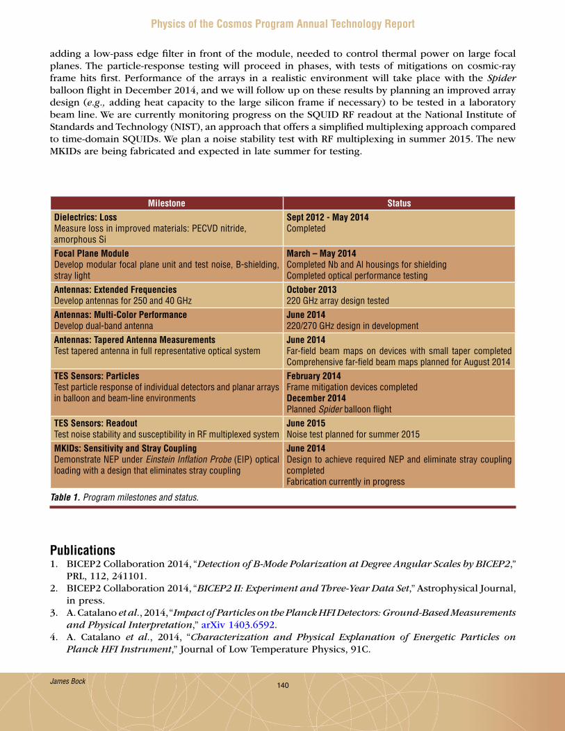
140
Physics of the Cosmos Program Annual Technology Report
adding a low-pass edge filter in front of the module, needed to control thermal power on large focal planes . The particle-response testing will proceed in phases, with tests of mitigations on cosmic-ray frame hits first . Performance of the arrays in a realistic environment will take place with the Spider balloon flight in December 2014, and we will follow up on these results by planning an improved array design (e.g., adding heat capacity to the large silicon frame if necessary) to be tested in a laboratory beam line . We are currently monitoring progress on the SQUID RF readout at the National Institute of Standards and Technology (NIST), an approach that offers a simplified multiplexing approach compared to time-domain SQUIDs . We plan a noise stability test with RF multiplexing in summer 2015 . The new MKIDs are being fabricated and expected in late summer for testing .
Table 1. Program milestones and status.
Milestone StatusDielectrics: LossMeasure loss in improved materials: PECVD nitride, amorphous Si
Sept 2012 - May 2014Completed
Focal Plane ModuleDevelop modular focal plane unit and test noise, B-shielding, stray light
March – May 2014Completed Nb and Al housings for shieldingCompleted optical performance testing
Antennas: Extended FrequenciesDevelop antennas for 250 and 40 GHz
October 2013220 GHz array design tested
Antennas: Multi-Color PerformanceDevelop dual-band antenna
June 2014220/270 GHz design in development
Antennas: Tapered Antenna MeasurementsTest tapered antenna in full representative optical system
June 2014Far-field beam maps on devices with small taper completed Comprehensive far-field beam maps planned for August 2014
TES Sensors: ParticlesTest particle response of individual detectors and planar arrays in balloon and beam-line environments
February 2014Frame mitigation devices completedDecember 2014Planned Spider balloon flight
TES Sensors: ReadoutTest noise stability and susceptibility in RF multiplexed system
June 2015Noise test planned for summer 2015
MKIDs: Sensitivity and Stray CouplingDemonstrate NEP under Einstein Inflation Probe (EIP) optical loading with a design that eliminates stray coupling
June 2014Design to achieve required NEP and eliminate stray coupling completed Fabrication currently in progress
James Bock
Publications1 . BICEP2 Collaboration 2014, “Detection of B-Mode Polarization at Degree Angular Scales by BICEP2,”
PRL, 112, 241101 .2 . BICEP2 Collaboration 2014, “BICEP2 II: Experiment and Three-Year Data Set,” Astrophysical Journal,
in press .3 . A . Catalano et al., 2014, “Impact of Particles on the Planck HFI Detectors: Ground-Based Measurements
and Physical Interpretation,” arXiv 1403 .6592 .4 . A . Catalano et al., 2014, “Characterization and Physical Explanation of Energetic Particles on
Planck HFI Instrument,” Journal of Low Temperature Physics, 91C .

141
Physics of the Cosmos Program Annual Technology Report
James Bock
5 . Planck Collaboration: P . Ade et al., 2013, “Planck 2013 Results X. Energetic Particle Effects: Characterization, Removal and Simulation,” A&A in press (arXiv 1303 .5071) .
6 . R . O’Brient et al., 2012, “Antenna-coupled TES bolometers for the Keck Array, Spider, and Polar-1,” SPIE 8452E, 1GO .
7 . R . C . O’Brient et al., 2012, “Suppressing Beam Systematics in Antenna-Coupled TES Bolometers for CMB Polarimetry,” JLTP 167, 497 .
For additional information, contact James Bock: [email protected]
142
Physics of the Cosmos Program Annual Technology Report
Abstracts of New SAT Projects Starting in FY 2015 David Burrows – “Fast Event Recognition for the ATHENA Wide Field Imager” . . . . . . . . . . . 143
Randall McEntaffer – “Reflection Grating Modules: Alignment and Testing” . . . . . . . . . . . . . . 144
Paul Reid – “Development of 0 .5 Arcsec Adjustable Grazing-Incidence
X-ray Mirrors for the SMART-X Mission Concept” . . . . . . . . . . . . . . . . . . . . . . . . . . . . . . . 145
Mark Schattenburg – “Advanced Packaging for Critical Angle X-ray Transmission Gratings” . . 146
William Zhang – “Affordable and Lightweight High-Resolution Astronomical X-Ray Optics” . . 147

143
Physics of the Cosmos Program Annual Technology Report
Fast Event Recognition for the ATHENA Wide Field ImagerPI: David Burrows (Penn State University)
AbstractThe next major X-ray astronomy observatory will be ESA’s L2 mission, which is likely to be the Advanced Telescope for High-energy Astrophysics (ATHENA) . One of the core ATHENA instruments, the Wide-Field Imager (WFI), is designed to conduct sensitive observations of both bright and faint X-ray sources using a wide field of view and a new type of device known as a DEPFET (Depleted P-channel Field Effect Transistor) detector, which has an extremely rapid readout capability . A key technology required to read out and process the data from an array of DEPFET detectors is a very high speed hardware/firmware event recognition processor . We have developed a design concept and are seeking funds to advance the design to TRL 4 .
For additional information, contact David Burrows: [email protected]

144
Physics of the Cosmos Program Annual Technology Report
Reflection Grating Modules: Alignment and TestingPI: Randall McEntaffer (University of Iowa)
AbstractThe goal of our Strategic Astrophysics Technology (SAT) program is to mature the technology readiness of off-plane X-ray reflection gratings, a critical technology for X-ray astrophysics as defined in the Physics of the Cosmos (PCOS) Program Annual Technology Report (PATR) . A high-throughput, high-spectral-resolution X-ray grating spectrometer (XGS) can address key future science goal such as the detection of the Warm-Hot Intergalactic Medium (WHIM), which is thought to contain nearly half of all baryonic matter in our universe . Recent mission studies at a variety of scales including Observatory class (the International X-ray Observatory; IXO), Explorer class (the Warm-Hot Intergalactic Medium Explorer; WHIMEx), and probe class (the Notional X-ray Grating Spectrometer; N-XGS) have determined appropriate XGS performance requirements are spectral resolving power of 3000 (lambda/delta lambda), and effective area up to 1000 cm2 over a ~0 .3-1 .5 keV energy range . An Off-Plane X-ray Grating Spectrometer (OP-XGS) can reach these goals when coupled with a large area, modest resolution telescope .
Our previous studies, including a SAT program that ended earlier this year, have identified a path forward to increase the technology readiness level (TRL) of the OP-XGS to TRL 6, ready for flight development upon definition of the next X-ray mission . We worked closely with the PCOS program on the Technology Development Plan as it pertains to reflection gratings . These efforts have enabled definition of key steps that need to be taken in the coming years . Among these is the need for increased fidelity in the areas of grating alignment and testing . The effort proposed here intends to address these issues and develop our alignment methods, our module mount designs, and our performance/environmental testing procedures . This proposal leverages heavily from previous efforts enabling us to identify specific milestones that can be obtained within a two year SAT program . The synergy realized from our previous and existing programs allow us to accomplish these tasks on a reasonable timeframe and minimal budget .
For additional information, contact Randall McEntaffer: [email protected]

145
Physics of the Cosmos Program Annual Technology Report
Development of 0.5 Arcsec Adjustable Grazing-Incidence X-ray Mirrors for the SMART-X Mission ConceptPI: Paul Reid (Smithsonian Institution/Smithsonian Astrophysical Observatory)
AbstractThis proposal is for the development of 0 .5 arc-second adjustable grazing incidence X-ray optics from the current TRL 3 to higher technology readiness levels, as necessary to support the SMART-X mission concept . Our work will advance the optical system TRL by incorporating the development of 0 .25 arc-second, multiple X-ray shell alignment and mounting, developing flight-like mounting, and demonstration of meeting the vibro-acoustic environment of launch . We will build upon our planned TRL 4 development (planned Sept ’15) by X-ray testing a multiple X-ray shell system . In addition, we will initiate the development and industry discussions to increase the size of the adjustable mirrors from their present 10 cm × 10 cm (limited by our coating chamber) to full size (~ 20 cm × 20 to 40 cm), making use of industry capabilities . We will also continue real-time lifetime testing of piezoelectric test mirrors in a space-like environment (vacuum, radiation, spacecraft survival temperatures, etc .) begun earlier, to accrue long-term data on thin-film piezoelectric performance .
For additional information, contact Paul Reid: [email protected]
146
Physics of the Cosmos Program Annual Technology Report
Advanced Packaging for Critical Angle X-ray Transmission GratingsPI: Mark Schattenburg (MIT)
AbstractWith NASA support, MIT has developed a new type of lightweight, high-efficiency, high-resolution diffraction structure called the critical angle X-ray transmission (CAT) grating . Technology development effort over the last several years has produced a number of promising prototype gratings with diffraction efficiency approaching predicted levels . MIT proposes to develop improved grating fabrication processes and new packaging technology designed to produce flight-quality grating elements with technology readiness progressing from TRL 3 to TRL 5 . Proposed grating fabrication process improvements are designed to boost process yield and grating throughput . We also propose to develop technology for bonding grating elements to flight-like metal frames and for attaching frames to prototype grating array structures . Grating elements, frames, fasteners, and support plates need to be engineered to survive launch and space conditions and prevent distortion or damage to gratings due to thermal expansion and other forces . We propose to test grating structures with metrology tests such as X-ray diffraction efficiency and UV period mapping, under representative flight conditions, in order to validate progress to advanced TRL nodes .
For additional information, contact Mark Schattenburg: [email protected]
147
Physics of the Cosmos Program Annual Technology Report
Affordable and Lightweight High-Resolution Astronomical X-Ray OpticsPI: William Zhang (NASA/GSFC)
AbstractAffordable and lightweight high-resolution X-ray optics are vital for the future of X-ray astronomy . We propose to further develop the slumped-glass mirror technology, improving its performance and technical readiness to enable several Explorer missions in this decade and help the X-ray astronomical community secure a major mission in the upcoming Decadal Survey .
In the last two years, we have significantly advanced the slumped-glass mirror technology, repeatedly building mirror modules that pass spaceflight environmental tests and achieve full-illumination X-ray images of 10”, thereby demonstrating that this technology has reached TRL 5 for building 10” X-ray mirror assemblies . As of early 2014, this technology can achieve angular resolution that is comparable to XMM-Newton’s with 10 times less mass, and is 10 times better than Suzaku’s with comparable mass . We propose to continue developing this technology until it reaches Chandra’s angular resolution with mass and cost comparable to those of Suzaku by the end of this decade .
The current apparent 11” image quality comes from three nearly equal contributions: (1) 7” from mirror segments (i.e., substrates plus coating), (2) 7” from alignment and bonding, and (3) 5” from gravity distortion caused by the horizontal orientation of the X-ray beam line . In the next two years, we will reduce all three contributions . We will use a new configuration for glass slumping and optimize the coating and annealing process to reduce the mirror segments’ contribution to 3”, refine the mirror alignment and bonding process to reduce its contribution to less than 3” as well, and build a vertical soft X-ray beam to reduce the gravity distortion by more than an order of magnitude to 0 .3” . We expect the image quality of this technology to improve from 10” to 5” by the end of 2016, while preserving its light weight and low cost, thus reaching TRL 5 for building 5” mirror assemblies . This technology will then enable a number of Explorer missions and be a credible backup technology for ESA’s upcoming ATHENA mission . In addition, we expect this work to help pave the way for developing a process of making ~1” X-ray optics by the time the next Decadal Survey gets underway, enabling the X-ray astronomical community to compete effectively for a major mission in the 2020s .
For additional information, contact William Zhang: [email protected]

148
Physics of the Cosmos Program Annual Technology Report
Appendix C – Acronyms AAAS . . . . . . . . . . American Astronomical SocietyADC . . . . . . . . . . Analog-to-Digital ConverterADR . . . . . . . . . . Adiabatic demagnetization refrigerationAEGIS . . . . . . . . Astrophysics Experiment for Grating and Imaging SpectroscopyAGN . . . . . . . . . . Active Galactic NucleiAIP . . . . . . . . . . Astrophysics Implementation PlanAO . . . . . . . . . . . Announcement of OpportunityAOM . . . . . . . . . Acousto-Optic ModulatorAPD . . . . . . . . . . Astrophysics DivisionAPRA . . . . . . . . . Astrophysics Research and AnalysisAPS . . . . . . . . . . Active Pixel SensorAR . . . . . . . . . . . Anti-ReflectionASCA . . . . . . . . . Advanced Satellite for Cosmology and AstrophysicsATHENA . . . . . . Advanced Telescope for High-Energy AstrophysicsAXAF. . . . . . . . . . Advanced X-ray Astrophysics FacilityAXSIO . . . . . . . . Advanced X-ray Spectroscopic Imaging Observatory
BBI . . . . . . . . . . . Back-IlluminatedBICEP . . . . . . . . Background Imaging of Cosmic Extragalactic PolarizationBOX . . . . . . . . . . Buried OxideBRDF . . . . . . . . . Bi-directional Reflectance Distribution FunctionBW . . . . . . . . . . Bandwidth
CCAD . . . . . . . . . . Computer-Aided DesignCAT . . . . . . . . . . Critical Angle TransmissionCATXGS . . . . . . . Critical Angle Transmission X-ray Grating SpectrometerCCD . . . . . . . . . . Charge-Coupled DeviceCDA . . . . . . . . . . Centroid Detector AssemblyCDM . . . . . . . . . Code Division MultiplexingCMB . . . . . . . . . Cosmic Microwave BackgroundCMM . . . . . . . . . Coordinate Measuring MachineCMNT . . . . . . . . Colloid Micro-Newton ThrusterCo-I . . . . . . . . . Co-InvestigatorCon-X . . . . . . . . Constellation-XCOR . . . . . . . . . . Cosmic OriginsCOTS . . . . . . . . . Commercial off the ShelfCPU . . . . . . . . . . Central Processing UnitCPW . . . . . . . . . Co-Planar Waveguide CST . . . . . . . . . . Community Science TeamCTE . . . . . . . . . . Coefficient of Thermal ExpansionCY . . . . . . . . . . . Calendar Year
DDC . . . . . . . . . . . Direct Currentddr . . . . . . . . . . Delta-Delta-RadiusDEPFET . . . . . . . Depleted P-channel Field Effect Transistor
149
Physics of the Cosmos Program Annual Technology Report
DIOS . . . . . . . . . Diffuse Intergalactic Oxygen SurveyorDOF . . . . . . . . . . Degree of FreedomDRIE . . . . . . . . . Deep Reactive-Ion EtchDRS . . . . . . . . . . Disturbance Reduction SystemDSP . . . . . . . . . . Digital Signal ProcessorDWS . . . . . . . . . Differential Wave-front Sensing
EECL . . . . . . . . . . External Cavity LaserEED . . . . . . . . . . Encircled-Energy DiameterEIP . . . . . . . . . . Einstein Inflation ProbeeLISA . . . . . . . . . evolved Laser Interferometer Space AntennaEM . . . . . . . . . . . Electro-MagneticEM . . . . . . . . . . . Engineering ModelEOM . . . . . . . . . Electro-Optic ModulatorESA . . . . . . . . . . European Space AgencyESI . . . . . . . . . . . Early-Stage InnovationExEP . . . . . . . . . Exo-Planet Exploration Program
FFar-IR . . . . . . . . . Far-InfraredFEA . . . . . . . . . . Finite Element AnalysisFEM . . . . . . . . . . Finite Element ModelFI . . . . . . . . . . . . Front-IlluminatedFOV . . . . . . . . . . Field of ViewFPGA . . . . . . . . . Field Programmable Gate ArrayFSM . . . . . . . . . . Fast Steering MirrorFSR . . . . . . . . . . Free Spectral RangeFWHM . . . . . . . . Full-Width at Half-MaximumFY . . . . . . . . . . . Fiscal Year
GGAS . . . . . . . . . . Grating Array StructureGFE . . . . . . . . . . Government Furnished EquipmentGPS . . . . . . . . . . Global Positioning SatelliteGRACE . . . . . . . . Gravity Recovery and Climate ExperimentGRS . . . . . . . . . . Gravitational Reference SensorGSE . . . . . . . . . . Ground Support EquipmentGSFC . . . . . . . . . Goddard Space Flight CenterGW . . . . . . . . . . Gravitational WaveGWO . . . . . . . . . Gravitational Wave Observatory
HHERO . . . . . . . . High Energy Replicated OpticsHETGS . . . . . . . . High Energy Transmission Grating SpectrometerHFI . . . . . . . . . . High Frequency InstrumentHPD . . . . . . . . . Half-Power DiameterHQ . . . . . . . . . . HeadquartersHR . . . . . . . . . . . High Reflectivity
150
Physics of the Cosmos Program Annual Technology Report
IIBS . . . . . . . . . . Ion Beam SputteringIDC . . . . . . . . . . Interdigitated CapacitorIP . . . . . . . . . . . Inflation ProbeIR . . . . . . . . . . . InfraredIRAD . . . . . . . . . Internal Research and DevelopmentIXO . . . . . . . . . . International X-ray Observatory
JJAXA . . . . . . . . . Japanese Aerospace Exploration AgencyJHU . . . . . . . . . . Johns Hopkins UniversityJILA . . . . . . . . . . Joint Institute for Laboratory AstrophysicsJPL . . . . . . . . . . . Jet Propulsion LaboratoryJWST . . . . . . . . . James Webb Space Telescope
KKDP . . . . . . . . . . Key Decision PointKID . . . . . . . . . . Kinetic Inductance Detector (or Device)
LLATOR . . . . . . . . Laser Astrometric Test of RelativityLCD . . . . . . . . . . Liquid Crystal DisplayLED . . . . . . . . . . Light-Emitting DiodeLIDAR . . . . . . . . Light Detection and RangingLIGO . . . . . . . . . Laser Interferometer Gravitational-wave ObservatoryLISA . . . . . . . . . . Laser Interferometer Space AntennaLO . . . . . . . . . . . Local OscillatorLPF . . . . . . . . . . LISA PathfinderLTP . . . . . . . . . . Lisa Technology PackageL1 . . . . . . . . . . . Level 1L2 . . . . . . . . . . . Level 2
MMBE . . . . . . . . . . Molecular Beam EpitaxyMDP . . . . . . . . . Maximum Design PressureMEMS . . . . . . . . Micro-Electrical-Mechanical SystemMEOP . . . . . . . . Maximum Expected Operating PressureMIDEX . . . . . . . . Medium-class ExplorerMIT . . . . . . . . . . Massachusetts Institute of TechnologyMKI . . . . . . . . . . MIT Kavli InstituteMKID . . . . . . . . . Microwave Kinetic Inductance Detector (or Device)MOPA . . . . . . . . Master Oscillator/Power AmplifierMSFC . . . . . . . . . Marshall Space Flight CenterMSM . . . . . . . . . Magnetic Smart Material
NNAC . . . . . . . . . . NASA Advisory CouncilNANOGrav . . . . . North American Nanohertz Observatory for Gravitational WavesNASA . . . . . . . . . National Aeronautics and Space AdministrationND . . . . . . . . . . . Neutral DensityNear-IR . . . . . . . Near-InfraredNEP . . . . . . . . . . Noise Equivalent PowerNGO . . . . . . . . . New Gravitational-wave Observatory

151
Physics of the Cosmos Program Annual Technology Report
NGXO . . . . . . . . Next Generation X-ray ObservatoryNICE-OHMS . . . . Noise-immune cavity-enhanced optical-heterodyne molecular spectroscopyNISP . . . . . . . . . Near Infrared Spectrometer and PhotometerNIST . . . . . . . . . National Institute of Standards and TechnologyNPR . . . . . . . . . . NASA Procedural RequirementsNPRO . . . . . . . . Non-planar Ring OscillatorNRC . . . . . . . . . . National Research CouncilNuSTAR . . . . . . . Nuclear Spectroscopic Telescope ArrayN-WFI . . . . . . . . Notional Wide-Field ImagerNWNH . . . . . . . . New Worlds, New Horizons in Astronomy and Astrophysics (2010 Decadal Survey)N-XGS . . . . . . . . Notional X-ray Grating Spectrometer
OOAP . . . . . . . . . . Optical Assembly PathfinderOBF . . . . . . . . . . Optical Blocking FilterOCT . . . . . . . . . . Office of the Chief TechnologistOGRE . . . . . . . . Off-plane Grating Rocket ExperimentOP-XGS . . . . . . . Off-Plane X-ray Grating SpectrometerOSIRIS-REx . . . . Origins Spectral Interpretation Resource Identification Security-Regolith Explorer
PPAG . . . . . . . . . . Program Analysis GroupPATR . . . . . . . . . Program Annual Technology ReportPCIe . . . . . . . . . . Peripheral Component Interconnect ExpressPCOS . . . . . . . . . Physics of the CosmosPDH . . . . . . . . . Pound-Drever-HallPDR . . . . . . . . . . Preliminary Design ReviewPECVD . . . . . . . . Plasma-Enhanced Chemical Vapor DepositionPhysPAG . . . . . . Physics of the Cosmos Program Analysis GroupPI . . . . . . . . . . . Principal InvestigatorPM . . . . . . . . . . . Phase MeterPMS . . . . . . . . . . Phase-Measurement SubsystemPPP . . . . . . . . . . Program Prioritization PanelPRISM . . . . . . . . Polarized Radiation Imaging and Spectroscopy MissionPRN . . . . . . . . . . Pseudo-Random NoisePSF . . . . . . . . . . Point Spread FunctionPSU . . . . . . . . . . Penn State UniversityPTA . . . . . . . . . . Pulsar Timing Array
QQE . . . . . . . . . . . Quantum Efficiency
RREXIS . . . . . . . . REgolith X-ray Imaging SpectrometerRF . . . . . . . . . . . Radio FrequencyRFI . . . . . . . . . . Request for InformationRFP . . . . . . . . . . Request for ProposalsRFQ . . . . . . . . . . Request for QuotesRGS . . . . . . . . . . Reflection Grating SpectrometerRIN . . . . . . . . . . Relative Intensity Noise

152
Physics of the Cosmos Program Annual Technology Report
rms . . . . . . . . . . Root-Mean-Squarermss . . . . . . . . . . Root-Mean-Square-SurfaceROSES . . . . . . . . Research Opportunities in Space and Earth ScienceRTF . . . . . . . . . . Roman Technology FellowshipR&D . . . . . . . . . . Research and Development
SSAO . . . . . . . . . . Smithsonian Astrophysical ObservatorySAT . . . . . . . . . . Strategic Astrophysics TechnologySB . . . . . . . . . . . SidebandSBIR . . . . . . . . . Small Business Innovation ResearchSEM . . . . . . . . . . Scanning Electron MicrographSGO . . . . . . . . . . Space-based Gravitational-wave ObservatorySIG . . . . . . . . . . Science Interest GroupSM . . . . . . . . . . . Steering MirrorSMART-X . . . . . . Square Meter Arcsecond Resolution X-ray TelescopeSMBH . . . . . . . . Supermassive Black HoleSMD . . . . . . . . . . Science Mission DirectorateSMEX . . . . . . . . . Small ExplorerSOI . . . . . . . . . . Silicon-on-InsulatorSQUID . . . . . . . . Superconducting Quantum Interference DeviceSR&T . . . . . . . . . Supporting Research and TechnologySST . . . . . . . . . . Science Study TeamSTAR . . . . . . . . . Space-Time Asymmetry ResearchSTMD . . . . . . . . . Space Technology Mission DirectorateSTOP . . . . . . . . . Structural-Thermal-Optical PerformanceSTRO . . . . . . . . . Space Technology Research OpportunitiesST7 . . . . . . . . . . Space Technology 7
TTDM . . . . . . . . . Technology Development ModuleTDM . . . . . . . . . Time-Division MultiplexingTDR . . . . . . . . . . Technology Development RoadmapTES . . . . . . . . . . Transition Edge SensorTFT . . . . . . . . . . Thin Film TransistorsTLS . . . . . . . . . . Two-Level SystemTMB . . . . . . . . . . Technology Management BoardTPC . . . . . . . . . . Time Projection ChamberTPCOS . . . . . . . . Technology Development for Physics of the CosmosTRL . . . . . . . . . . Technology Readiness Level
UUK . . . . . . . . . . . United KingdomULE . . . . . . . . . . Ultra-Low ExpansionUSO . . . . . . . . . . Ultra-Stable OscillatorUV . . . . . . . . . . . Ultraviolet
VVCO . . . . . . . . . . Voltage-Controlled Oscillator

153
Physics of the Cosmos Program Annual Technology Report
WWFI . . . . . . . . . . Wide-Field ImagerWFIRST . . . . . . . Wide-Field Infrared Survey TelescopeWFS . . . . . . . . . . Wavefront SensorWFXT . . . . . . . . Wide-Field X-ray TelescopeWHIM . . . . . . . . Warm-Hot Intergalactic MediumWHIMEx . . . . . . Warm-Hot Intergalactic Medium ExplorerWMAP . . . . . . . . Wilkinson Microwave Anisotropy Probe
XXCSR . . . . . . . . . X-ray mission Concepts Study ReportXGS . . . . . . . . . . X-ray Grating SpectrometerX-IFU . . . . . . . . . X-ray Integral Field UnitXMM-Newton . . . X-ray Multi-mirror Mission – NewtonXMS . . . . . . . . . . X-ray Microcalorimeter Spectrometer
Other2D . . . . . . . . . . . Two Dimensional2G . . . . . . . . . . . 2nd Generation3G . . . . . . . . . . . 3rd GenerationΛCDM . . . . . . . . Lambda Cold Dark Matter