438916720en my pro version ny - electroluxtools.professional.electrolux.com/...438916720en... · of...
TRANSCRIPT
Service manual
Washer extractor
WE170V, WE170P
438 9167-20/EN 2015.03.03Original instructions

3
INDEX 1 General information .................................................................................................................................. 6 2 WARNINGS .............................................................................................................................................. 7 3 Control panel ............................................................................................................................................ 8
3.1 General characteristics ...................................................................................................................... 8 3.2 General Characteristics and Control Panel ........................................................................................ 9 3.3 Programme selector knob .................................................................................................................. 9 3.4 Pushbuttons ....................................................................................................................................... 9
3.4.1 On/off button ................................................................................................................................. 9 3.4.2 Spin time button ............................................................................................................................ 9 3.4.3 Option buttons .............................................................................................................................. 9 3.4.4 Delay start button ........................................................................................................................ 10 3.4.5 Start/pause button ...................................................................................................................... 10
3.5 Display ............................................................................................................................................. 11 3.5.1 Spin time digits ........................................................................................................................... 11 3.5.2 Phases symbols .......................................................................................................................... 11 3.5.3 Child Lock ................................................................................................................................... 12 3.5.4 Delay .......................................................................................................................................... 12 3.5.5 Time Digits .................................................................................................................................. 12 3.5.6 Extra Rinse symbol ..................................................................................................................... 12 3.5.7 No softner symbol ....................................................................................................................... 12
4 Functionalities ......................................................................................................................................... 13 4.1 On/Off Button ................................................................................................................................... 13 4.2 Stand-Off mode behavior ................................................................................................................. 13 4.3 Cycle start / pause / change ............................................................................................................ 13 4.4 Hi-fi Selector .................................................................................................................................... 14 4.5 Buttons Combinations ...................................................................................................................... 14
4.5.1 Child Lock mode ......................................................................................................................... 14 4.5.2 Demo mode ................................................................................................................................ 15 4.5.3 Diagnostic mode ......................................................................................................................... 15
4.6 Buzzer ............................................................................................................................................. 15 4.7 Display behaviors ............................................................................................................................ 15
4.7.1 Child lock symbol ........................................................................................................................ 15 4.7.2 Cycle Phases symbols ................................................................................................................ 15
4.8 Faults/warnings signals ................................................................................................................... 16 4.8.1 Selection error ............................................................................................................................ 16 4.8.2 Warnings .................................................................................................................................... 16
5 DEMO MODE ......................................................................................................................................... 17 5.1 Access to DEMO settings ................................................................................................................ 17 5.2 Exiting DEMO mode ........................................................................................................................ 17
6 DIAGNOSTICS SYSTEM ....................................................................................................................... 18 6.1 Accessing diagnostics ..................................................................................................................... 18 6.2 Quitting the diagnostics system ....................................................................................................... 18 6.3 Diagnostic test phases ..................................................................................................................... 19
7 ALARMS ................................................................................................................................................. 21 7.1 Displaying the alarms to the user ..................................................................................................... 21 7.2 Reading the alarms .......................................................................................................................... 22 Rapid reading of alarms ................................................................................................................................. 23 7.3 Deleting the last alarm ..................................................................................................................... 23
8 OPERATING TIME COUNTER............................................................................................................... 24 8.1 Reading the operating time .............................................................................................................. 24 8.2 Display of total operating time .......................................................................................................... 24
9 Options ................................................................................................................................................... 25 9.1 Description of options ...................................................................................................................... 25
10 TECHNICAL CHARACTERISTICS ......................................................................................................... 27 10.1 Detergent container ......................................................................................................................... 28
10.1.1 Operating principle ...................................................................................................................... 28 10.1.2 Arranging the flap in the detergent container .............................................................................. 29
10.2 Detergent container and hoses - WE170V ....................................................................................... 30 10.3 Detergent container and hoses - WE170P ....................................................................................... 31 10.4 Drain pump ...................................................................................................................................... 32 10.5 Filter dial .......................................................................................................................................... 32 10.6 Washing unit .................................................................................................................................... 33
4
10.7 Electronic control ............................................................................................................................. 34 10.8 Anti-disturbance filter ....................................................................................................................... 35
10.8.1 General characteristics ............................................................................................................... 35 10.9 Display board ................................................................................................................................... 35 10.10 Drain valve ....................................................................................................................................... 36
10.10.1 Working phases .......................................................................................................................... 38 10.10.2 Replacement of drain valve ........................................................................................................ 39
10.11 Heating element .............................................................................................................................. 40 10.11.1 General characteristics ............................................................................................................... 40
10.12 Temperature sensor ........................................................................................................................ 41 10.12.1 General characteristics ............................................................................................................... 41
10.13 Water level sensor ........................................................................................................................... 42 10.13.1 General characteristics ............................................................................................................... 42
10.14 Door lock safety interlock ................................................................................................................. 43 10.14.1 General characteristics ............................................................................................................... 43 10.14.2 Operating principle ...................................................................................................................... 43
10.15 Three-phase asynchronous motor - Inverter .................................................................................... 45 10.15.1 General characteristics ............................................................................................................... 45 10.15.2 Power supply to motor ................................................................................................................ 45
10.16 Inverter (Motor Control Unit) ............................................................................................................ 46 10.16.1 General characteristics ............................................................................................................... 46
10.17 Solenoid valves ............................................................................................................................... 47 10.17.1 General characteristics ............................................................................................................... 47
10.17.1.1 Operating principle .......................................................................................................... 47 10.17.1.2 Mechanical jamming of the solenoid valve ...................................................................... 47 10.17.1.3 Low water pressure ......................................................................................................... 47 10.17.1.4 Diagram .......................................................................................................................... 48
10.18 Flowmeter ........................................................................................................................................ 49 10.18.1 General characteristics ............................................................................................................... 49 10.18.2 Operating principle of the flowmeter ........................................................................................... 50
10.19 Drum light ........................................................................................................................................ 51 11 ALARM SUMMARY TABLE (Note that some alarms might not be valid for your appliance) ................... 52
11.1 Alarm codes for appliance with coin meter or external liquid supply system .................................... 56 11.2 Detailed description of alarm codes ................................................................................................. 56
11.2.1 E9A - External liquid supply system configured but communication failure (before payment) ..... 56 11.2.2 EF9 — External liquid supply system configured but communication failure (after payment) ...... 56
12 ACCESSIBILITY .................................................................................................................................... 57 12.1 Worktop ........................................................................................................................................... 57 12.2 From the worktop, you can access .................................................................................................. 57
12.2.1 Main board .................................................................................................................................. 57 12.2.2 Solenoid valve ............................................................................................................................ 59 12.2.3 Control panel .............................................................................................................................. 59 12.2.4 Display board/light diffuser/button springs/buttons assembly ...................................................... 61 12.2.5 Water level sensor ...................................................................................................................... 63 12.2.6 Detergent container .................................................................................................................... 63 12.2.7 Detergent fill pipe ........................................................................................................................ 64 12.2.8 Upper counterweight ................................................................................................................... 64
12.3 Accessing the front part ................................................................................................................... 64 12.3.1 Door hinge - Door ....................................................................................................................... 64 12.3.2 Door safety interlock ................................................................................................................... 65 12.3.3 Drum light ................................................................................................................................... 66 12.3.4 Bellow seal ................................................................................................................................. 66 12.3.5 Blade .......................................................................................................................................... 67 12.3.6 Front panel ................................................................................................................................. 69
12.4 From the front panel, you can access .............................................................................................. 70 12.4.1 Front counterweight .................................................................................................................... 70 12.4.2 Shock absorber ........................................................................................................................... 70 12.4.3 Drain water circuit ....................................................................................................................... 71 12.4.4 Pressure chamber ...................................................................................................................... 71 12.4.5 Tub suspension springs .............................................................................................................. 73 12.4.6 Shock absorber pin ..................................................................................................................... 74
12.5 Accessing the rear part .................................................................................................................... 75 12.5.1 Back panel .................................................................................................................................. 75
12.6 From the back panel, you can access .............................................................................................. 75
5
12.6.1 Belt ............................................................................................................................................. 75 12.6.2 Plastic pulley ............................................................................................................................... 76 12.6.3 Inverter ....................................................................................................................................... 76 12.6.4 Motor .......................................................................................................................................... 77 12.6.5 Heating element .......................................................................................................................... 77 12.6.6 Rear shock absorber .................................................................................................................. 77 12.6.7 Welded tub assembly ................................................................................................................. 78 12.6.8 Drain pipe/cabling support .......................................................................................................... 78 12.6.9 Main drain pipe ........................................................................................................................... 78
13 External liquid supply connection ............................................................................................................ 79 13.1 Replacement of the external liquid supply I/O board ........................................................................ 79 13.2 Setting of the dip switches ............................................................................................................... 79 13.3 Uninstall the external liquid supply ................................................................................................... 80 13.4 Pump signal schedule ...................................................................................................................... 80
6
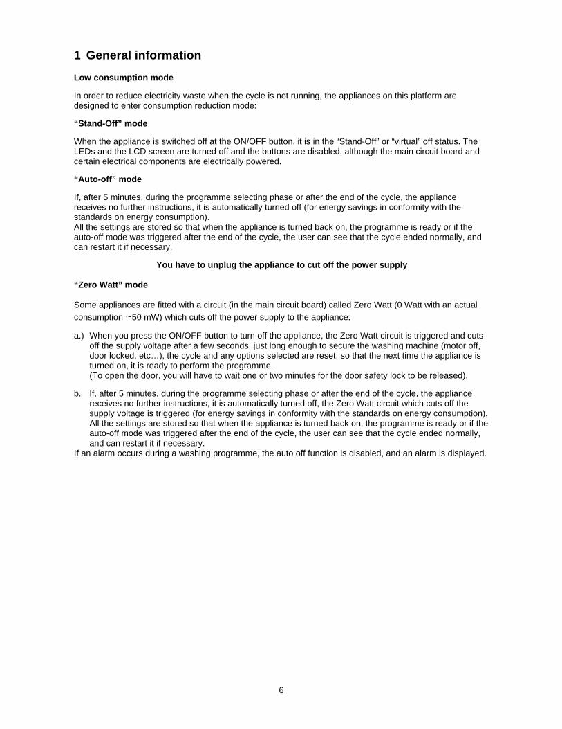
1 General information Low consumption mode In order to reduce electricity waste when the cycle is not running, the appliances on this platform are designed to enter consumption reduction mode: “Stand-Off” mode When the appliance is switched off at the ON/OFF button, it is in the “Stand-Off” or “virtual” off status. The LEDs and the LCD screen are turned off and the buttons are disabled, although the main circuit board and certain electrical components are electrically powered. “Auto-off” mode If, after 5 minutes, during the programme selecting phase or after the end of the cycle, the appliance receives no further instructions, it is automatically turned off (for energy savings in conformity with the standards on energy consumption). All the settings are stored so that when the appliance is turned back on, the programme is ready or if the auto-off mode was triggered after the end of the cycle, the user can see that the cycle ended normally, and can restart it if necessary.
You have to unplug the appliance to cut off the power supply “Zero Watt” mode Some appliances are fitted with a circuit (in the main circuit board) called Zero Watt (0 Watt with an actual
consumption ~50 mW) which cuts off the power supply to the appliance: a.) When you press the ON/OFF button to turn off the appliance, the Zero Watt circuit is triggered and cuts
off the supply voltage after a few seconds, just long enough to secure the washing machine (motor off, door locked, etc…), the cycle and any options selected are reset, so that the next time the appliance is turned on, it is ready to perform the programme. (To open the door, you will have to wait one or two minutes for the door safety lock to be released).
b. If, after 5 minutes, during the programme selecting phase or after the end of the cycle, the appliance receives no further instructions, it is automatically turned off, the Zero Watt circuit which cuts off the supply voltage is triggered (for energy savings in conformity with the standards on energy consumption). All the settings are stored so that when the appliance is turned back on, the programme is ready or if the auto-off mode was triggered after the end of the cycle, the user can see that the cycle ended normally, and can restart it if necessary.
If an alarm occurs during a washing programme, the auto off function is disabled, and an alarm is displayed.

7
2 WARNINGS
Any work on electrical appliances must only be carried out by qualified
technicians.
Before you access internal components, take the plug out of the socket to cut the power supply.
Make resistance measurements, rather than direct voltage and current
measurements When replacing the heating element, replace it with one
that has the same characteristics (2 thermal fuses) in order not to compromise the safety of the appliance. Do not remove/switch the NTC sensors between heating elements.
Always empty the appliance of all the water before laying it
on its side (see the relevant paragraph). Never place the appliance on its right side (electronic control system side): some
of the water in the detergent dispenser could leak onto the electrical/electronic components and cause these to burn.
When replacing components, please refer to the code shown in the list of spare
parts relating to the appliance.

8
3 Control panel
3.1 General characteristics The control/display circuit board, inserted in
a plastic box, secured to the control panel (the figure illustrates: the display board with the side socket in which the selector is fixed, connected together by a flat cable, and the display board assembly).
The main circuit board is positioned at the rear of the appliance, receives commands from the display
board, powers the electrical components as well as communicating with the motor control board (Inverter).
Positioning of LEDs and buttons Display board assembly, exploded view 1. Selector board protection 2. Display board protection 3. LCD display 4. Display board and selector board 5. Rear protection
1 2 3
4 5

9
3.2 General Characteristics and Control Panel Application pictures1:
The main characteristics are: Hi-fi selector with 16 LEDs (positions) associated; On/Off mechanical tact-switch button always on board; 7 function buttons:
o Pre rinse button; o Pre wash button; o 2 option buttons; o Spin time button; o Delay start button; o Start/pause button with 1 associated LED;
Small LCD custom display, negative red; All the LEDs are red.
3.3 Programme selector knob
Refer to “Functionalities” chapter for a detailed description of Hi-fi selector usage.
3.4 Pushbuttons
3.4.1 On/off button
Refer to “Functionalities” chapter for a detailed description of On/Off usage.
3.4.2 Spin time button
The spin time is initially set to default value for that program. Each time the related button is pressed, the time value is decreased by following pre-defined steps: 6m, 4m, 2m, 45s, 30s , 15s, 10s, 5s; once reached the minimum allowed time (5 seconds) it restarts from the maximum time (configurable also on selector).
3.4.3 Option buttons
The four option buttons without associated LED are used to select: Pre Rinse Pre Wash Extra Rinse No Softner
1 Remark: the pictures are only demonstrative, not in the final graphical release.

10
When pressing the button the option is enabled or disabled. When the option is enabled the associated ICON switches on and cycle duration is updated in display digits.
3.4.4 Delay start button
The delay buttons is associated with one dedicated icon on the LCD. When the delay is active the icon is switched on, both during program setup and delay phase in progress. Each time the button is pressed, the delay time increase in the following way:
Up to 90 minutes in steps of 30 minutes From 2 to 70 hours in steps of 1 hours
After “70h”, pressing again the button, the function is deactivated. Once the delay has been set and after 3 seconds of no key presses the digits will display again the program duration. To see the delay time again, press once the button. After the machine is started the display will show the delay time counting down. After cycle start, selected delay time can only be cancelled (machine must be put in pause first).
3.4.5 Start/pause button
The Start/Pause is used to start the cycle once the program and options have been set. Pressing the button during the cycle will pause the machine to allow changing options or possibly open the door porthole (if necessary conditions of temperature and water level are met). Press again to restart cycle. The associated LED blinks slowly during programme setup, during the pause; it is lighted on steadily when the cycle is in execution; it is lighted off when the cycle is ended with the door unlocked.
11
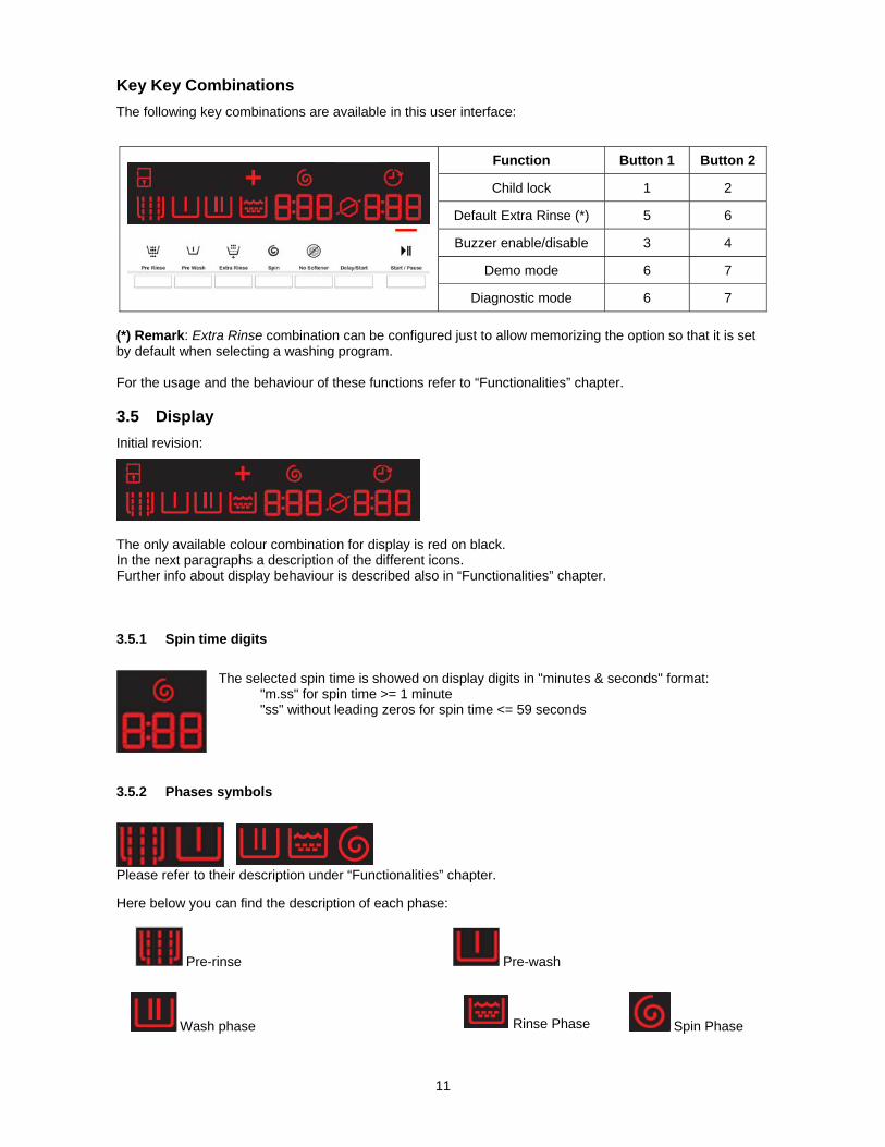
Key Key Combinations
The following key combinations are available in this user interface:
(*) Remark: Extra Rinse combination can be configured just to allow memorizing the option so that it is set by default when selecting a washing program. For the usage and the behaviour of these functions refer to “Functionalities” chapter.
3.5 Display
Initial revision:
The only available colour combination for display is red on black. In the next paragraphs a description of the different icons. Further info about display behaviour is described also in “Functionalities” chapter.
3.5.1 Spin time digits
The selected spin time is showed on display digits in "minutes & seconds" format: "m.ss" for spin time >= 1 minute "ss" without leading zeros for spin time <= 59 seconds
3.5.2 Phases symbols
Please refer to their description under “Functionalities” chapter. Here below you can find the description of each phase:
Pre-rinse Pre-wash
Wash phase Rinse Phase Spin Phase
Function Button 1 Button 2
Child lock 1 2
Default Extra Rinse (*) 5 6
Buzzer enable/disable 3 4
Demo mode 6 7
Diagnostic mode 6 7
12
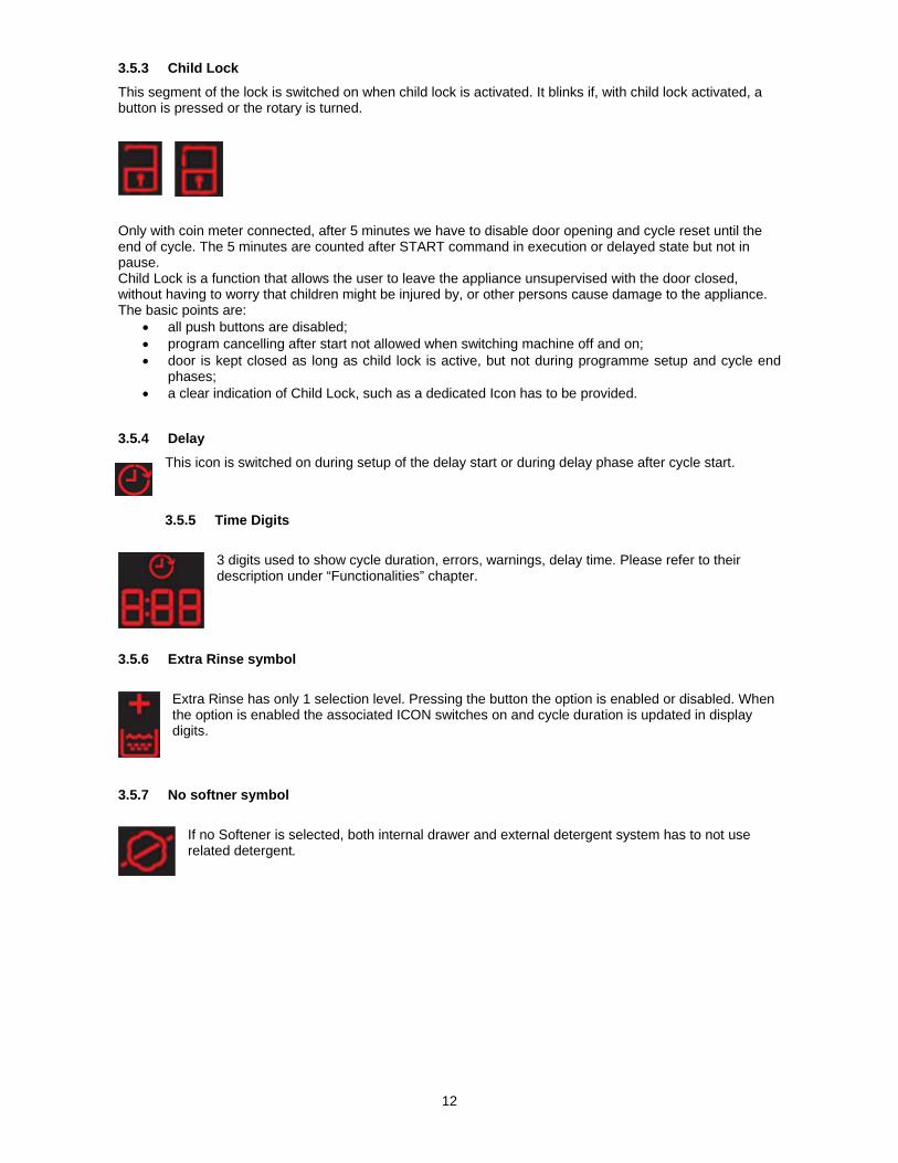
3.5.3 Child Lock
This segment of the lock is switched on when child lock is activated. It blinks if, with child lock activated, a button is pressed or the rotary is turned.
Only with coin meter connected, after 5 minutes we have to disable door opening and cycle reset until the end of cycle. The 5 minutes are counted after START command in execution or delayed state but not in pause. Child Lock is a function that allows the user to leave the appliance unsupervised with the door closed, without having to worry that children might be injured by, or other persons cause damage to the appliance. The basic points are:
all push buttons are disabled; program cancelling after start not allowed when switching machine off and on; door is kept closed as long as child lock is active, but not during programme setup and cycle end
phases; a clear indication of Child Lock, such as a dedicated Icon has to be provided.
3.5.4 Delay
This icon is switched on during setup of the delay start or during delay phase after cycle start.
3.5.5 Time Digits
3 digits used to show cycle duration, errors, warnings, delay time. Please refer to their description under “Functionalities” chapter.
3.5.6 Extra Rinse symbol
Extra Rinse has only 1 selection level. Pressing the button the option is enabled or disabled. When the option is enabled the associated ICON switches on and cycle duration is updated in display digits.
3.5.7 No softner symbol
If no Softener is selected, both internal drawer and external detergent system has to not use related detergent.
13
4 Functionalities
4.1 On/Off Button
The aesthetics levels of the WE170P/V have a dedicated On/Off button always present. This button could put the machine in a special low power consumption mode. To switch on the appliance, simply press shortly the button. The user interface plays the dedicated jingle (if buzzer is enabled) and switches the lights and display on according to default programme. To switch off the appliance, press and hold the button for about 1 second. After this time, the user interface plays the dedicated jingle (if buzzer is enabled) and all lights and display are switched off. All selected options and the possible programme in progress are reset.
4.2 Stand-Off mode behavior
When the machine is switched off via On/Off button, the appliance goes in Stand-Off mode where it is “virtually switched off”: all LEDs and display are lighted off and buttons are disabled, but the electronic boards are supplied anyway.
4.3 Cycle start / pause / change
When a programme is selected and the door porthole is closed, to start the cycle simply press the Start/Pause button: related LED stops flashing and becomes steady while the display (if present) updates accordingly. Pressing Start/Pause button during the cycle the machine is paused: if door unlocks it means there are the conditions to open it and add laundry, usually during the first minutes after water load. In pause it is allowed changing options, but not programmes: in this case a reset via On/Off button is needed. In all cases the display updates switching from cycle end indication to pause or execution state: time digits show updated time to end.
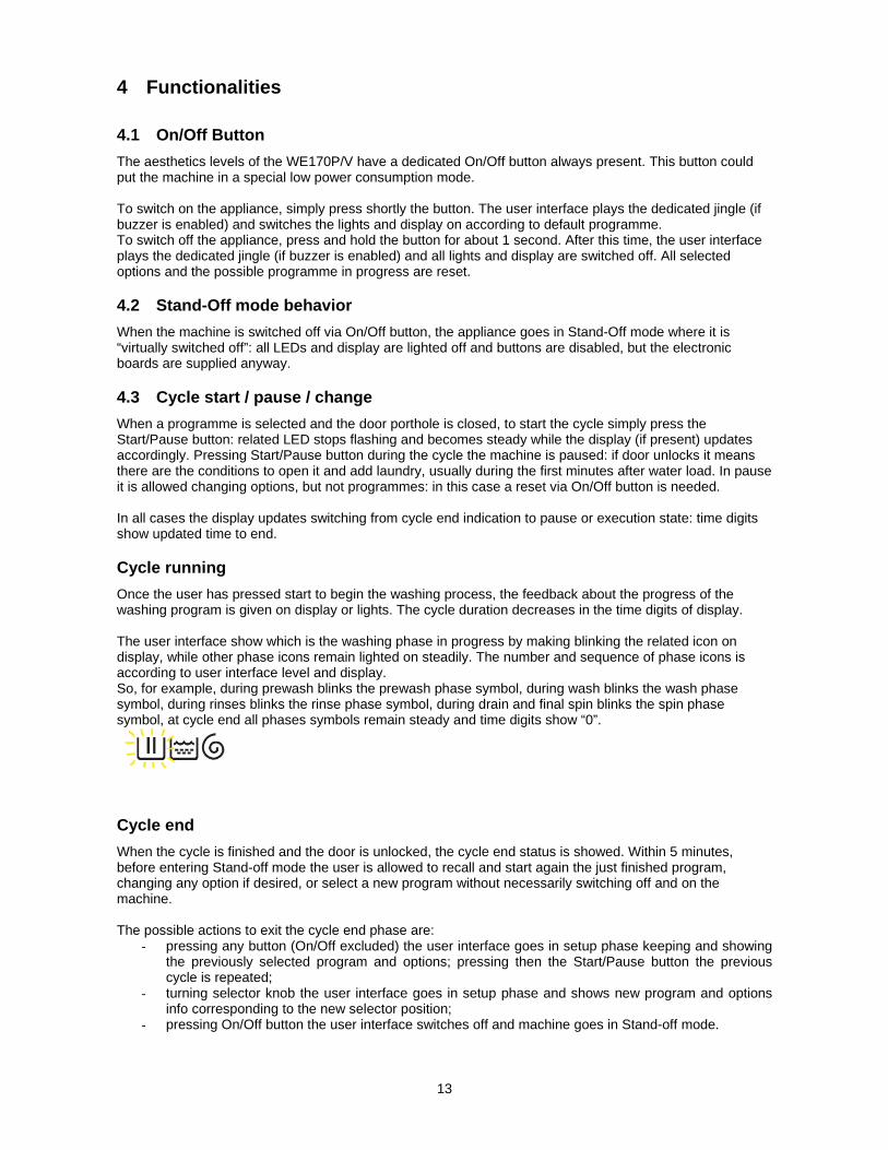
Cycle running
Once the user has pressed start to begin the washing process, the feedback about the progress of the washing program is given on display or lights. The cycle duration decreases in the time digits of display. The user interface show which is the washing phase in progress by making blinking the related icon on display, while other phase icons remain lighted on steadily. The number and sequence of phase icons is according to user interface level and display. So, for example, during prewash blinks the prewash phase symbol, during wash blinks the wash phase symbol, during rinses blinks the rinse phase symbol, during drain and final spin blinks the spin phase symbol, at cycle end all phases symbols remain steady and time digits show “0”.
Cycle end
When the cycle is finished and the door is unlocked, the cycle end status is showed. Within 5 minutes, before entering Stand-off mode the user is allowed to recall and start again the just finished program, changing any option if desired, or select a new program without necessarily switching off and on the machine. The possible actions to exit the cycle end phase are:
- pressing any button (On/Off excluded) the user interface goes in setup phase keeping and showing the previously selected program and options; pressing then the Start/Pause button the previous cycle is repeated;
- turning selector knob the user interface goes in setup phase and shows new program and options info corresponding to the new selector position;
- pressing On/Off button the user interface switches off and machine goes in Stand-off mode.

14
4.4 Hi-fi Selector
The number of position is not configurable and it is always 16, since it is strictly linked to the programme lights. Compared to a traditional absolute selector, the Hi-fi one has no index on the knob and no reset position. The knob itself doesn’t point to any position in the control panel; hence the selected programme is indicated by the associated LED. To reset a cycle in progress just press the On/Off button. When the machine is switched on, the upper right position is selected by default (if no “special modes, e.g. diagnostic, return from power fails, demo mode etc). When the rotary is turned clockwise or anti-clockwise in setup, the corresponding LED of selected programme is lighted on and the LCD display info changes accordingly.
4.5 Buttons Combinations
Some additional extra functions can be set using “buttons combinations”, that is keeping pressed together for some seconds specific couples of buttons. Push buttons combinations can be configured for following functions:
Function Meaning
Default Extra Rinse
Used to set and store Extra Rinse option. This function keeps its last selected status (set or deselect) also after machine switching off. Settable only during the programme setup for those cycles where the option is available; the feedback is given on dedicated Extra Rinse LCD icon.
Buzzer on/off
Activates/deactivates the buzzer. This function keeps its last selected status (set or deselect) also after machine switching off. Settable during the programme setup; the feedback is given by 2 short beeps when deactivating sounds, by 1 click when re-activating sounds.
Child Lock Mode
Locks the user interface to prevent children changing program setup or starting the cycle. This function keeps its last selected status (set or deselect) also after machine switching off. Always settable; the feedback is given on Child Lock LED or icon inside the display.
Demo mode
Demonstration mode, to show to customers in the sales shop how the machine works by simulating the washing cycle. Settable within 7 seconds from machine switching on; the feedback is given by “dEM” text flashing on cycle time digits for 3 seconds. Demo mode remains active also after machine switching off via On/Off button; pressing On button again will flash “dEM” or LEDs as above described. Unplug machine to exit mode.
Diagnostic Mode
Factory/Service mode for machine testing. The mode is exited when switching machine off. Settable within 7 seconds from machine switching on; the feedback is given by all LEDs or LCD icons flashing in sequence.
Diagnostic and Demo modes can be set only within 7 seconds from machine switching on, provided that selected programme position is the first for Diagnostic and the third for Demo. Further info on some of such functions is provided following.
4.5.1 Child Lock mode
Child Lock is a function that allows the user to leave the appliance unsupervised with the door closed, without having to worry that children might be injured by, or other persons cause damage to the appliance. The basic points are:
all push buttons are disabled; program cancelling after start not allowed when switching machine off and on; door is kept closed as long as child lock is active, but not during programme setup and cycle end
phases; a clear indication of Child Lock, such as a dedicated Icon has to be provided.
Push buttons All push buttons are disabled as long as Child Lock is active. Only On/Off and buttons combination to unlock machine and to enter in diagnostic mode are always enabled. Cancelling the program To cancel a running program after cycle start, Child Lock has to be deactivated first pressing the foreseen buttons combination and then the machine has to be switched-off.

15
If the machine is switched-off and on during cycle execution without unlocking it, cycle automatically continues like after a power failure situation. Door status After cycle start, the door is kept locked as far as the cycle end is reached. To open it if needed before cycle end, Child Lock has to be deactivated first pressing the foreseen buttons combination and then pausing the machine pressing Start/Pause button: if the machine is in safety conditions (low water level and low temperature) the door device unlocks. If the machine is switched-off during cycle execution for more than one minute (door lock device unlocks in the meantime), when it is switched-on again the door is automatically locked, unless it has been manually opened in the meantime: in this second case machine wakes up in pause and waits for user confirmation to go on with cycle execution (pressing Start button after that Child Lock has been deactivated).
4.5.2 Demo mode
Demonstration mode is used to show to customers in the sales shop how to interact with user interface panel and how the machine works by simulating the washing cycle. The appliance works and can be operated in the same way as in normal user mode, allowing to select any program with washing options in order to see cycle time and how options can affect it. The difference in Demo Mode is that, once the cycle is started, only the motor moves: actions such as water loading, water draining and heating are not performed since they cannot be managed in the shop.
4.5.3 Diagnostic mode
Diagnostic mode is used by factory or service people to test the machine and check for possible faults by reading the alarms status history.
4.6 Buzzer
A multi-tone buzzer is provided to sound in following cases: - switching machine on and off, with 2 different short jingles; - pressing a button, with a very short “click” sound; - when the cycle is finished, for about 2 minutes with a specific sequence of three long beeps (1sec
on - 1 sec off - 1sec on - 1 sec off - 1sec on) repeated every 15 seconds; - when alarms/warnings occur, for about 5 minutes with a specific sequence of three short beeps
repeated 3 times every 15. - during program selection, when knob moves, with a very short “click” sound as pushbuttons.
The buzzer can be active or not by configuration; anyway the default factory setting has to be active to meet the norms regarding eyesight handicap people. To deactivate it the specific push buttons combination has to be used (see “Buttons Combinations” paragraph). When deactivated the buzzer doesn’t play the on/off jingles and cycle end melody, while sounds anyway in case of button “click”, knob movements and alarm/warnings occurrence. Volume level is pre-fixed and can’t be changed by user.
4.7 Display behaviors
4.7.1 Child lock symbol
This symbol shows the status locked/unlocked of the user interface. When child lock is set, related icon on display is lighted-on. Pressing any button, the icon blinks for a while to remind that the user interface is locked.
4.7.2 Cycle Phases symbols
Cycle phase icons are lighted-on steadily during the setup phase to show which phases are included in the cycle. During cycle execution, the icon of the phase in progress blinks every half a second, remains steady when the phase has passed; same behaviour if the machine is paused during the cycle.
16
4.8 Faults/warnings signals
4.8.1 Selection error
The selection errors are noticed to customer by a flashing “Err” text on cycle time digits; buzzer doesn’t sound a specific melody and Start/Pause LED doesn’t flash. The signalling is displayed for about 1 second in following cases:
- if coin meter is present and the user try to start a cycle without payment; - when an incompatible option button with selected washing program has been pressed; - when an option button is pressed or the selector is moved during the cycle execution.
4.8.2 Warnings
When a machine fault is detected, a warning is displayed on cycle time digits with “Exx” format. The faults that are noticed to customer are:
- E10 : tap closed, due to water loading timeout - E20 : clogged filter, due to water draining timeout - E40 : door not properly closed, due to device locking timeout - E90 : no communication between main boards and coin operated machine or detergent dispenser - EF0 : detergent overdosing - EH0: mains supply problems, due to voltage/frequency out of standard working range
Warning code/message is displayed as long as the fault condition is present. The buzzer sounds for about 5 minutes, but not in case of EH0. For the first three codes, once the problem has been solved, pressing Start/Pause button the warning is not shown anymore and buzzer stops sequence.

17
5 DEMO MODE A special cycle is designed to demonstrate the operation of these appliances in shops, without connecting them to the water mains. This way, any one of the programmes can be selected and, once the start button/sensor has been pressed/touched (START/PAUSE), the appliance will only perform some of the phases of the programme, skipping those which cannot be performed (water fill, drain, heating). The cycle takes place as follows: the door lock is enabled regularly (door locked during operation, possibility of opening it at the end of the
cycle or when paused), Motor: all low speed movements are enabled, the pulses and spin are disabled, the water fill solenoid valves and the drain pump are disabled, display: as the cycle phases are very fast (one second in the demo cycle corresponds to approximately
one minute in the actual cycle) the end time decreases by 1 unit per second. Bear in mind that the end time does not always correspond to the actual cycle time.
5.1 Access to DEMO settings The operations listed below must be carried out within 7 seconds.
Do not start the machine with this combination of buttons pressed, only when accessing
diagnostic mode 1. Switch on the appliance using the ON/OFF button 2. Turn the selector dial until the third LED in the right-hand row is on. 3. Press the START/PAUSE button and the nearest option button simultaneously (as shown in the figure). 4. Hold the buttons down (approximately three or five seconds) until “dEM” flashes for a short time.
5.2 Exiting DEMO mode To quit the demo mode, unplug the appliance at the socket, because the ON/OFF button does not function.

18
6 DIAGNOSTICS SYSTEM
6.1 Accessing diagnostics The operations listed below must be carried out within 7 seconds.
Do not start the machine with this combination of buttons pressed, only when accessing
diagnostic mode 1. Switch on the appliance using the ON/OFF button. The first LED in the right hand row will light up. 2. Press the START/PAUSE button and the nearest option button simultaneously (as shown in the
figure). 3. Hold the buttons/sensors down/pressed until the LEDs and symbols begin to flash in sequence
(approximately 3 seconds). In the first position, the operation of the buttons, of the related LEDs and of the groups of symbols shown on the LCD screen is checked; turn the programme selector dial clockwise to run the diagnostic cycle for the operation of the various components and to read any alarms (see diagnostic testing on the following page). During this phase, if any key combination is pressed (except for the one relating to diagnostics), all the combinations of options stored are deleted (Extra rinse, No buzzer, etc..).
6.2 Quitting the diagnostics system To exit the diagnostic cycle, switch the appliance off, then back on and then off again.

19
6.3 Diagnostic test phases Irrespective of the type of PCB and the configuration of the programme selector, after entering the diagnostic mode, turn the programme selector dial clockwise to perform the diagnostic cycle for the operation of the various components and to read any alarms. Concurrently, a selector control code is shown on the LCD display, which indicates for two seconds the description in the last column of the table below. (all alarms are enabled in the diagnostic cycle).
Selector position
Components activated Working conditions Function tested LCD display
1
- The LEDs, groups of symbols in the LCD screen and the backlight of the display are turned on in sequence
- Press a button/sensor to turn on the group of icons in the LCD screen or the corresponding LED and the buzzer sounds at the same time
Always active. User interface functions.
2
- Door safety interlock - Wash solenoid
Door closed. Water level below anti-flooding level. Maximum time 5 mins.
Water fill to wash compartment.
Water level in the tub (mm)
3
- Door safety interlock - Pre-wash solenoid
Door closed. Water level below anti-flooding level. Maximum time 5 mins.
Water fill to pre-wash compartment
Water level in the tub (mm)
4
- Door safety interlock - Solenoid valve
pre-wash and wash
Door closed. Water level below anti-flooding level. Maximum time 5 mins.
Water fill to conditioner compartment.
Water level in the tub (mm)
5
- Door safety interlock - Third solenoid valve
Door closed. Water level below anti-flooding level. Maximum time 5 mins.
Water fill to third solenoid valve compartment.
Water level in the tub is displayed (mm)
6
- Door safety interlock - Fourth solenoid valve (hot
water where featured)
Door closed. Water level below anti-flooding level. Maximum time 5 mins.
Water fill to fourth solenoid valve compartment.
Water level in the tub is displayed (mm)
7
- Door safety interlock - Wash solenoid, if the water in
the tub is not enough to cover the heating element
- Heating element
Door closed. Water level above the heating element. Maximum time 10 mins up to 90 °C. (*)
Heating. Circulation.
Temperature in °C measured using the NTC probe
8
- Door safety interlock - Wash solenoid, if the water in
the tub is not enough to cover the heating element
- Motor (55 rpm clockwise, 55 rpm anti-clockwise, 250 rpm pulse)
Door closed. Water level above the heating element.
Check for leaks from the tub.
Drum speed in rpm/10

20
9
- Door safety interlock - Drain pump - Motor up to 650 rpm then at
maximum spin speed (**)
Door closed. Water level lower than anti-boiling level for spinning.
Drain, calibration of analogue pressure switch and spin.
Drum speed in rpm/10
11
- Reading/Deleting the last alarm ----- ----
12÷
16
- The LEDs, groups of symbols in the LCD screen and the backlight of the display are turned on in sequence
- Press a button/sensor to turn on the group of icons in the LCD screen or the corresponding LED and the buzzer sounds at the same time
Always active. User interface functions.
(*) In most cases, this time is sufficient to check the heating. However, the time can be increased by repeating the phase without draining the water: pass for a moment to a different phase of the diagnostic cycle and then back to the heating control phase (if the temperature is higher than 80 °C, heating does not take place). (**) The check at the maximum speed occurs without control of the A.G.S. and no garments must be inside the appliance.

21
7 ALARMS
7.1 Displaying the alarms to the user When a problem occurs in the appliance and a “WARNING” or “ALARM” is triggered, this is shown in the three digit display (where the time left to the end of the cycle is shown), this information ceases to be displayed when the problem is repaired/solved. The buzzer then emits a sound for 5 minutes. This does not occur for alarm EH0.
The alarms displayed to the user are listed below: E10 - Water fill difficulty (tap closed) E20 - Drain difficulty (filter dirty) E40 - Door open While for the alarm: EH0 – Voltage or frequency outside normal values It is necessary to wait for power supply voltage and/or frequency to restore normal conditions. The alarms are enabled during the execution of the washing programme. With the exception of alarms associated with the configuration and the power supply voltage/frequency, which are also displayed during the programme selection phase. The door can normally be opened (except where specified) when an alarm condition has occurred, on condition that: The level of the water in the tub is below a certain level. The water temperature is lower than 55 °C. The motor has stopped. Certain alarm conditions require a drain phase to be performed before the door can be opened for safety reasons: Cooling water fill if the temperature is higher than 65 °C. Drain until the analogue pressure switch is on empty, during a max. 3-minute interval.

22
7.2 Reading the alarms The last three alarms stored in the FLASH memory of the PCB can be displayed: enter the diagnostic mode. Irrespective of the type of PCB and configuration, turn the programme
selector knob clockwise to the eleventh position - the last alarm is then displayed.
to display previous alarms, press/touch the button/sensor to the left of the START/PAUSE button in sequence (as shown in the figure).
To return to the last alarm, press/touch the START/PAUSE button/sensor.
23
Rapid reading of alarms The last alarm can even be displayed if the selector is not in the tenth diagnostic position or if the appliance is in normal operating mode (for example when performing a wash programme): → Press the START/PAUSE button and the nearest option button simultaneously (as if you were entering DIAGNOSTIC mode) for at least 2 seconds: the LCD display shows the last alarm. → The alarm continues to be displayed until a button is pressed. → During the time that the alarm is displayed, the appliance continues to perform the cycle or, if you are in the programme selection phase, it retains the options selected previously in memory.
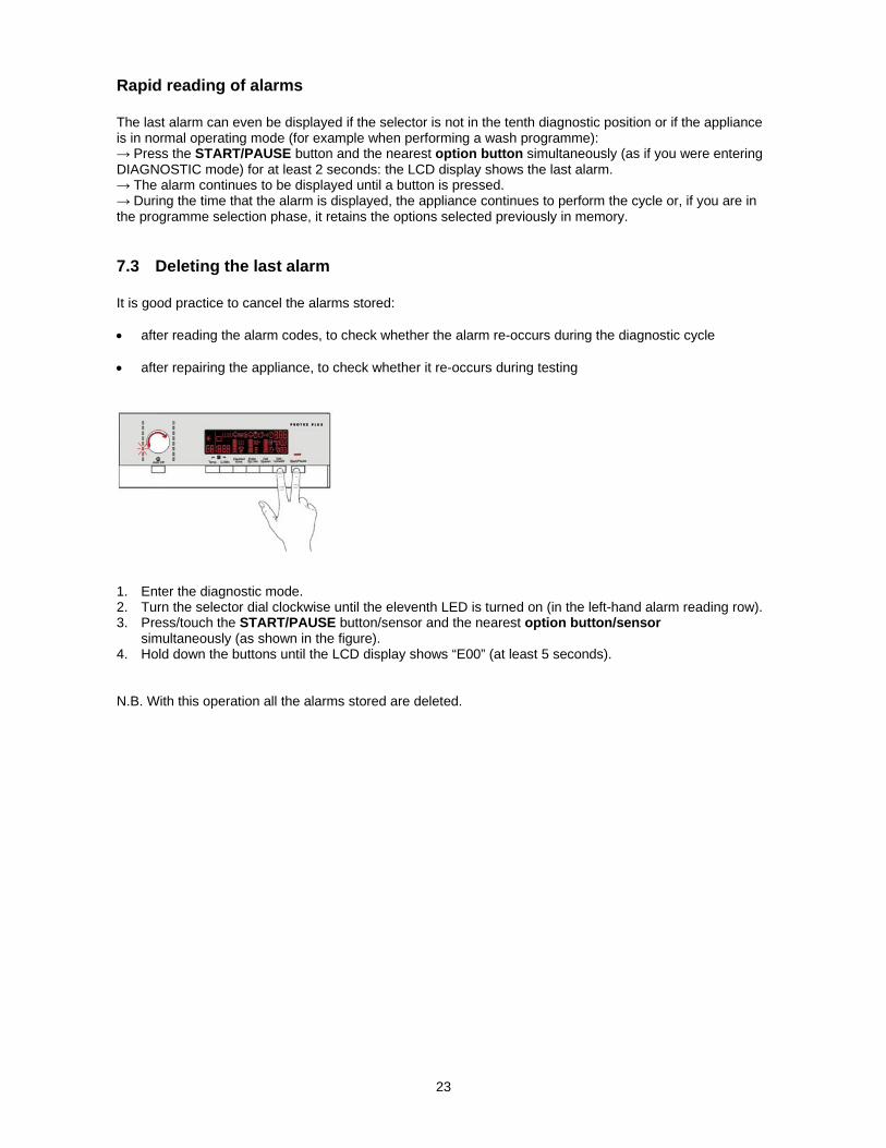
7.3 Deleting the last alarm It is good practice to cancel the alarms stored: after reading the alarm codes, to check whether the alarm re-occurs during the diagnostic cycle after repairing the appliance, to check whether it re-occurs during testing
1. Enter the diagnostic mode. 2. Turn the selector dial clockwise until the eleventh LED is turned on (in the left-hand alarm reading row). 3. Press/touch the START/PAUSE button/sensor and the nearest option button/sensor
simultaneously (as shown in the figure). 4. Hold down the buttons until the LCD display shows “E00” (at least 5 seconds). N.B. With this operation all the alarms stored are deleted.

24
8 OPERATING TIME COUNTER Using a specific procedure, the operator can display the total operating time for the appliance, which is counted from the moment it is first switched on. The unit can count up to a maximum of 6,550 hours of operating time. only the operating time of normal programmes (and not diagnostic cycles) is counted the actual operating time for the cycle is counted (which does not include pauses, delayed start time,
rinse hold time and soaking phases) the precision of the counter is 30 seconds per programme only whole hours of operation are counted (1 hr and 59 min = 1 hr)
8.1 Reading the operating time The operations listed below must be carried out within 7 seconds.
Do not start the machine with this combination of buttons pressed, only when accessing
diagnostic mode 1. Switch on the appliance using the ON/OFF button. 2. Turn the selector dial clockwise until the fifth LED in the right-hand row is on. 3. Press the START/PAUSE button and the nearest option button simultaneously (as shown in the
figure). 4. Hold down the buttons until the hours of operation appear on the display (at least 5 seconds).
8.2 Display of total operating time This time is displayed with a sequence of two digits at a time: the first two digits indicate thousands and hundreds, the second two digits indicate tens and units. For example, if the operating time is 6,550 hours, the display will show the following sequence:
Phase 2 Phase 3For two seconds, the following digits are displayed: thousands (6) hundreds (5)
For the next two seconds the following digits are displayed: tens (5) units (0).
At the end of phase three (after the tens and units are displayed), the cycle is repeated. To return to normal mode, either: switch the appliance off or press a button or turn the selector knob.
25
9 Options
9.1 Description of options
Rinse hold During the cycle the intermediate rinses and spins are performed. Stops the appliance with water in the tub before the final spin cycle. To drain the water, simply press the START/PAUSE button to run the drain and spin cycles.
Pre-wash Adds a pre-wash phase at the start of the cycle with water heating to 30 °C (or cold, if selected). In COTTON and SYNTHETICS cycles, performs a short spin before passing on to the washing phase. This option cannot be selected for WOOL and HAND WASH cycles.
Soak Adds a pre-wash phase with heating to 30 °C (or cold, if selected) plus 30’ hold with HAND WASH
movement. Completes the cycle.
Stains Adds a 5-minute motor movement phase after heating to 40 °C. Water flow to the pre-wash/stains compartment to introduce the special stain-removal product. This option cannot be selected for WOOL and HAND WASH cycles.
Super rinse (key combination). Adds two rinses in the COTTONS - SYNTHETICS - DELICATES cycles Eliminates the spin at the end of washing. EXTRA rinse Adds up to five rinses in the COTTONS - SYNTHETICS - DELICATES cycles. When the rinses are five or more, it eliminates the spins at the end of the washing. Maximum of 8 rinses in total.
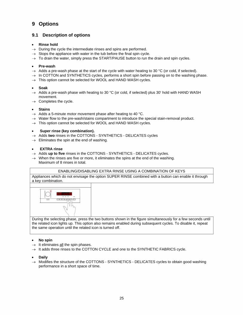
ENABLING/DISABLING EXTRA RINSE USING A COMBINATION OF KEYS
Appliances which do not envisage the option SUPER RINSE combined with a button can enable it through a key combination.
During the selecting phase, press the two buttons shown in the figure simultaneously for a few seconds until the related icon lights up. This option also remains enabled during subsequent cycles. To disable it, repeat the same operation until the related icon is turned off.
No spin It eliminates all the spin phases. It adds three rinses to the COTTON CYCLE and one to the SYNTHETIC FABRICS cycle.
Daily Modifies the structure of the COTTONS - SYNTHETICS - DELICATES cycles to obtain good washing
performance in a short space of time.
26
Super quick Modifies the structure of the wash phase of the COTTON - SYNTHETIC FABRICS - DELICATES cycles
by half a load.
Delayed start time Adds a pause before the start of the programme. The delay time is shown on the three digit display. To start the cycle immediately after the countdown to the delayed start has already begun:
press the Start/Pause button, cancel the delay time by pressing the relevant button, then press START/PAUSE again.
27
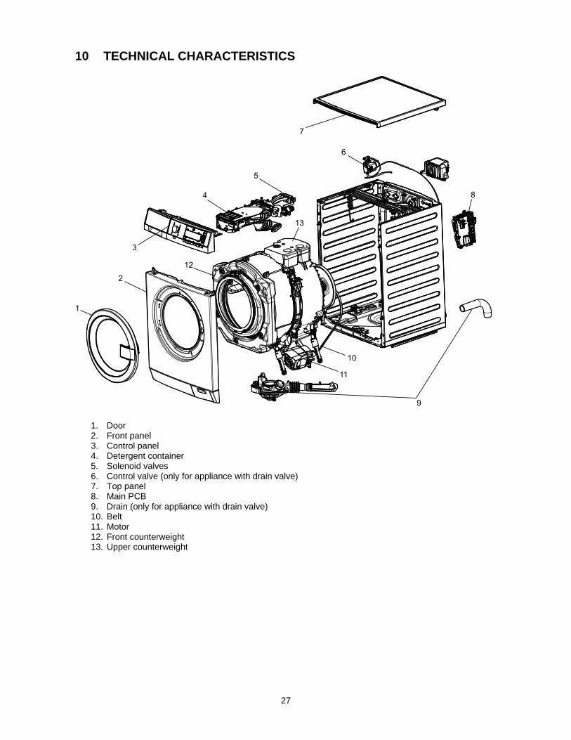
10 TECHNICAL CHARACTERISTICS
1
2
3
4
5
6
8
9
7
11
12
13
10
1. Door 2. Front panel 3. Control panel 4. Detergent container 5. Solenoid valves 6. Control valve (only for appliance with drain valve) 7. Top panel 8. Main PCB 9. Drain (only for appliance with drain valve) 10. Belt 11. Motor 12. Front counterweight 13. Upper counterweight

28
10.1 Detergent container The water in the detergent c is filled through one solenoid valve for cold water (with one inlet, and 3 outlets) and one for the hot water (with one inlet and one outlet);
Upper part of detergent cointainer
10.1.1 Operating principle
a b
c
Water fill to pre-wash compartment
(pre-wash solenoid)
The detergent in compartment “a” is loaded at the start of the pre-wash phase.
Water fill to wash compartment (wash solenoid)
Compartment “b” is used to contain the detergent loaded at
the start of washing.
Water fill to conditioner compartment(pre-wash and wash solenoid valves)
Compartment “c” is used for the conditioner, which is loaded at
the start of the final rinse. The pre-wash and wash solenoid valves are activated simultaneously.
Hot water filling (hot water solenoid)
The hot water solenoid valve is activated to fill water into the
washing compartment “b” together with the cold water.
29
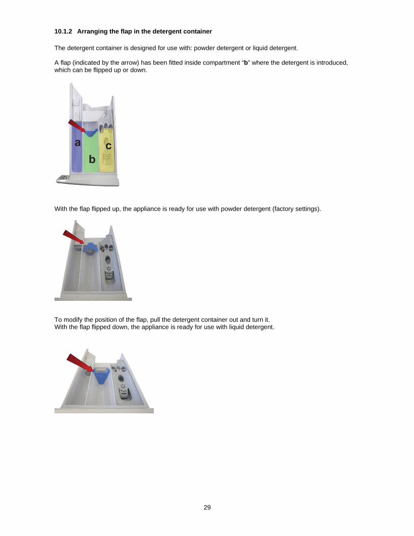
10.1.2 Arranging the flap in the detergent container
The detergent container is designed for use with: powder detergent or liquid detergent. A flap (indicated by the arrow) has been fitted inside compartment “b” where the detergent is introduced, which can be flipped up or down.
a b
c
With the flap flipped up, the appliance is ready for use with powder detergent (factory settings).
To modify the position of the flap, pull the detergent container out and turn it. With the flap flipped down, the appliance is ready for use with liquid detergent.
30
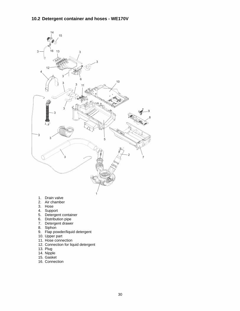
10.2 Detergent container and hoses - WE170V
1
2
3
3
33
3
3
3
3
3
3
3
4
5
6
7
8
9
1011
12
13
1415
16
1. Drain valve 2. Air chamber 3. Hose 4. Support 5. Detergent container 6. Distribution pipe 7. Detergent drawer 8. Siphon 9. Flap powder/liquid detergent 10. Upper part 11. Hose connection 12. Connection for liquid detergent 13. Plug 14. Nipple 15. Gasket 16. Connection

31
10.3 Detergent container and hoses - WE170P
1
2
3
3
33
3
3
3
3
4
5
6
7
8
9
10
11
12
13
14
15
16
17
18
19
1. Drain housing 2. Air chamber 3. Hose 4. Hose clamp 5. Support 6. Pump housing 7. Gasket 8. Cushion 9. Filter 10. Seal 11. Detergent cointainer 12. Distribution pipe 13. Detergent drawer 14. Siphon 15. Upper part 16. Hose connection 17. Connection for liquid detergent 18. Plug 19. Flap powder/liquid detergent

32
10.4 Drain pump
1. Ball lock ring with ball 2. Water level chamber 3. Drain pump 4. Filter body 5. Filter insert with labyrinth 6. Drainage lever
10.5 Filter dial
To drain the water, simply: press the two tabs that lock the plug closing lever, fig. 2, simultaneously extract the top part of the lever as shown by the yellow arrow in fig. 3, position the closing lever as shown in fig. 4.
Fig. 1 Fig. 2 Fig. 3 Fig. 4
1
2
3
4 5
6

33
10.6 Washing unit The washing unit is made up of: A back casing (1) and a front casing (2), welded together to form the welded tub. Inside this is the drum (5) (made of stainless steel) with the three blades (6) (in carboran) snap-fastened to the drum. To balance the unit during the washing movements and during the spin phases two counterweights are used on the appliance: one at the front (3) and one at the top (7). The bellow seal (4) is fixed at the front. The washing unit is suspended by two coil springs attached to the top crossbar, and the oscillations are dampened by three shock absorbers, two on the right and one on the left (looking straight at the front of the appliance).
Drum with three blades inside.
1
2
3
4 5
6
7

34
10.7 Electronic control The electronic control consists of:
1. Main circuit board. 2. Control/display circuit board. 3. INVERTER motor control board (not shown in the
figure, positioned at the bottom right of the appliance seen from the rear).
The control/display PCB contains: the selector dial, to select the washing programme, the LCD display, to display the programme information; the buttons to adjust the temperature, the spin speed and possibly select an option, the Start/PAUSE button and lastly the ON/OFF button. The commands received by the display board (by turning the selector dial, selecting an option, etc…) are sent to the main circuit board, which powers all the electrical components like: cold and hot water solenoid valves, motor control board, Inverter, drain pump/valve, heating element, door safety interlock, drum light. It controls the level of water via the analogue pressure sensor. It controls the state of the door. It controls the speed of the motor. It controls the temperature of the washing water via the NTC probe inserted in the heating element. It controls the voltage and frequency of the power supply and ensures they are close to the rated ones. It measures the flow of water through the solenoid using the flow meter. It simultaneously controls their functioning to guarantee the correct performance of the washing cycle.
21
Solenoid valve Hot waterProgram selector and
Display board
Main board
Drain pump or Drain valve
NTC Temperature
sensor
Door lock solenoid
Heating element Motor
Solenoid valve Cold water
Inverter
Water flowmeter
Drum light
Water level sensor

35
When replacing any of the components, please refer to the code shown in the list of spare parts relating to the appliance being repaired.
10.8 Anti-disturbance filter
10.8.1 General characteristics
This device is connected to the electricity power line input of the appliance and avoids the emission of radio frequency disturbances in the power network. It is incorporated into the main board. 1. Main circuit board
10.9 Display board The main circuit board (1) supplies the power supply voltage to the control/display board (12). It is possible to select the programmes by turning the selector. The options can be selected by pressing/touching the buttons/keys and the START/PAUSE button is used to start the machine or pause it. The buzzer - where featured - is powered by the display board. 1. Main circuit board 12. Display board
36
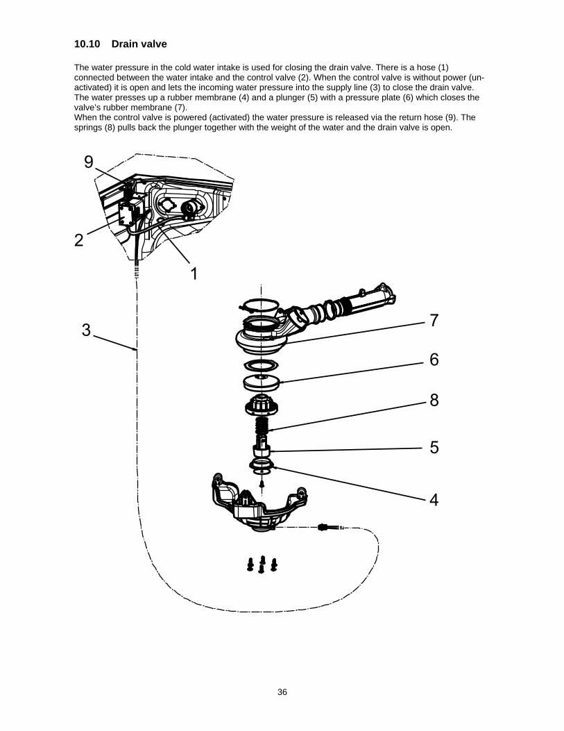
10.10 Drain valve The water pressure in the cold water intake is used for closing the drain valve. There is a hose (1) connected between the water intake and the control valve (2). When the control valve is without power (un-activated) it is open and lets the incoming water pressure into the supply line (3) to close the drain valve. The water presses up a rubber membrane (4) and a plunger (5) with a pressure plate (6) which closes the valve’s rubber membrane (7). When the control valve is powered (activated) the water pressure is released via the return hose (9). The springs (8) pulls back the plunger together with the weight of the water and the drain valve is open.
9
2
1
3 7
6
8
5
4

37
An electric three way control valve is used to control the water pressure. The inlet water pressure is used to close the drain valve. Opening is done by switching the control valve and action of return spring.
A B
C
E
F
D
A. Three way control valve B. Water supply C. To drain valve inlet D. Drain valve outlet E. Drain valve F. To drain outlet
38
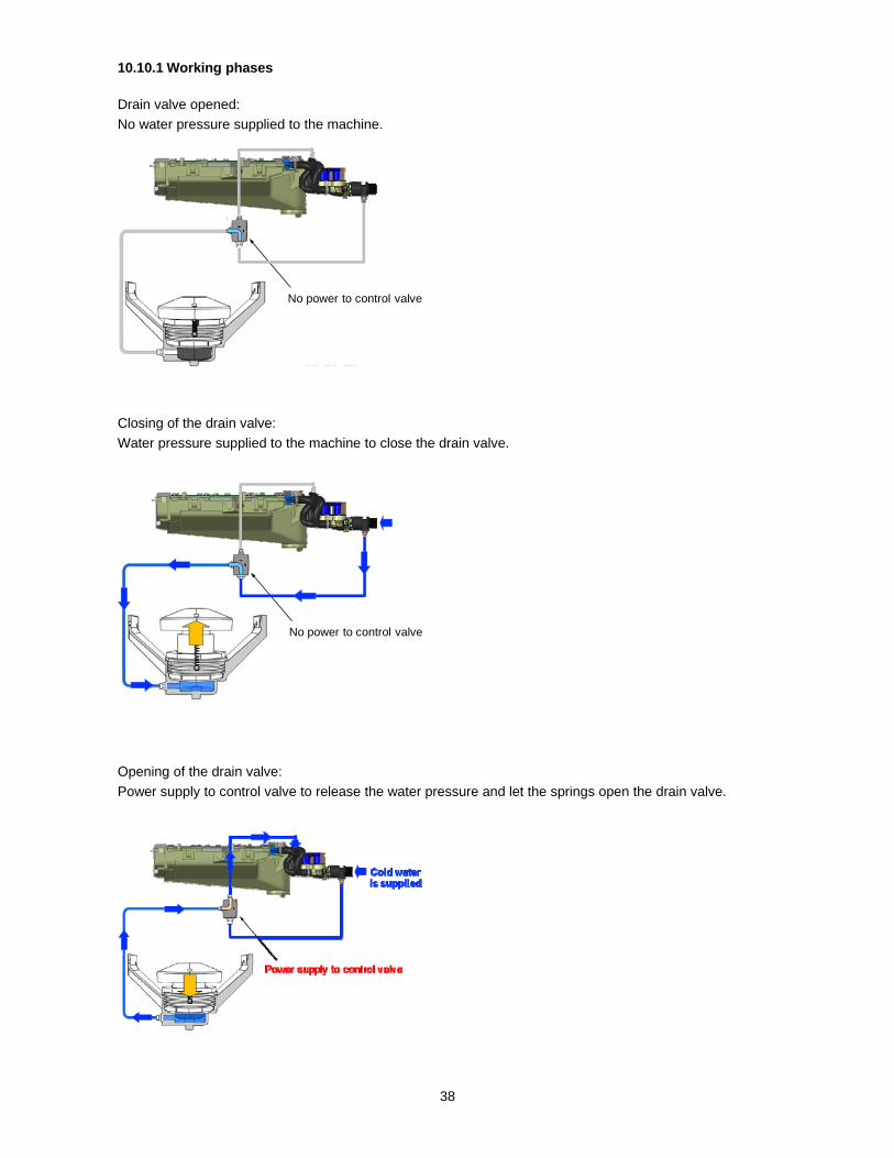
10.10.1 Working phases
Drain valve opened:
No water pressure supplied to the machine.
No power to control valve
Closing of the drain valve:
Water pressure supplied to the machine to close the drain valve.
No power to control valve
Opening of the drain valve:
Power supply to control valve to release the water pressure and let the springs open the drain valve.

39
10.10.2 Replacement of drain valve
Disconnect the power to the appliance. Demount the top panel. Demount the control panel. Demount the front panel and door. Loosen the hose clamps and demount the air chamber from the drain valve. Remove the hose from the valves nipple for water supply. (Press the orange ring and pull out the hose at the same time). Loosen and unscrew the three retaining screws of the valve and demount the drain valve.
Mount the new drain valve (and air chamber) and tighten the screws. Mount the hoses. Tighten the hose clamps. Remount the panels and door.

40
10.11 Heating element
When replacing the heating element, please refer to the code shown in the list of spare parts relating to the appliance.
It is strictly forbidden to tamper with the heating element in
any way!!! (e.g. changing the NTC probe, etc...)
10.11.1 General characteristics
1. NTC probe 2. Heating element The heating element of the washing water is armoured, i.e. it is inserted in sealed tubular stainless steel casing. It is powered by two relays (K1, K2) situated in the circuit board. It is fitted with two thermal fuses which trip if the temperature of the heating element exceeds the values for which they were calibrated. (In the event of a fault an alarm will be displayed - see table of alarms). 1. Main circuit board 11. Heating element
1
2
41
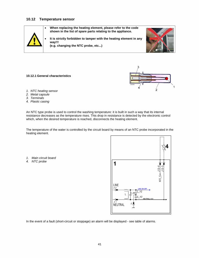
10.12 Temperature sensor
When replacing the heating element, please refer to the code shown in the list of spare parts relating to the appliance.
It is strictly forbidden to tamper with the heating element in any
way!!! (e.g. changing the NTC probe, etc...)
10.12.1 General characteristics
1. NTC heating sensor 2. Metal capsule 3. Terminals 4. Plastic casing An NTC type probe is used to control the washing temperature: it is built in such a way that its internal resistance decreases as the temperature rises. This drop in resistance is detected by the electronic control which, when the desired temperature is reached, disconnects the heating element. The temperature of the water is controlled by the circuit board by means of an NTC probe incorporated in the heating element. 1. Main circuit board 4. NTC probe In the event of a fault (short-circuit or stoppage) an alarm will be displayed - see table of alarms.

42
10.13 Water level sensor
10.13.1 General characteristics
The electronic water level sensor is an analogue device that controls the water level in the drum, and it is directly connected to the main PCB. 1. Small pipe 2. Core 3. Oscillating coil The water level sensor is connected via a pipe to the pressure chamber. When water is introduced into the drum, this creates a pressure inside the hydraulic circuit that causes the membrane to change position. This in turn modifies the position of the core inside the coil, thus changing the inductance and the frequency of the oscillating circuit. The PCB recognises how much water has been introduced into the drum according to the frequency. 1. Main circuit board 2. Analogue water level sensor Operating frequency variation according to the quantity of water in the tub. In the event of a fault an alarm will be displayed - see table of alarms.

43
10.14 Door lock safety interlock
10.14.1 General characteristics
The instantaneous door interlock allows the door to be opened as soon as the drum stops. If the conditions described further are met. In appliances with a drum light, a door safety interlock is fitted with an integrated switch (piloted via a slide from the door latch). The information about the position of the switch is sent to the main circuit board and consequently powers the LED or not. 1 Main circuit board 2 Door safety interlock (with micro-switch for the drum
light – WE170P/V)
10.14.2 Operating principle
1. Solenoid protection PTC 2. Solenoid 3. Lifting assembly 4. Cam 5. PTC - bi-metal 6. Electrical contacts (main switch) 7. Ratchet When the programme starts (start/pause button), the main circuit board sends a voltage pulse, lasting
20 msec, to the solenoid (at least 6 seconds must have passed since the appliance was turned on), which turns the position of the cam: the ratchet which locks the cursor of the door safety interlock is raised and simultaneously closes the contacts of the main switch, which powers all the appliance components.
When the programme ends, the circuit board sends two additional 20 msec pulses (200 msec apart): - the first pulse moves the cam by another position, without releasing the ratchet.
44
- the second pulse (which is only sent if everything is in working order) moves the cam to another position, which causes the ratchet to return to its position and therefore release the interlock; the contacts of the main switch are simultaneously opened.
Door open conditions Before pulses are sent to open the door, the PCB checks for the following conditions: the drum must be stationary (no signal from the tachometric generator) the water level must not be higher than the lower edge of the door the temperature of the water must not be higher than 40 °C. Automatic release device In the event of a power failure, turn the appliance off at the ON/OFF button, solenoid fault, the bi-metal PTC cools in between 55 seconds and about 4 minutes (with temperature of 65 °C) and therefore releases the door. Solenoid protection A PTC is connected in series to the solenoid to limit the current (and therefore any overheating) in the following cases: main circuit board triac short circuit many consecutive pressings of the start/pause button (more than 10 times)
45
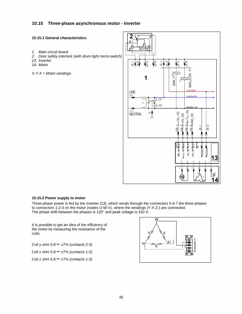
10.15 Three-phase asynchronous motor - Inverter
10.15.1 General characteristics
1. Main circuit board 2. Door safety interlock (with drum light micro-switch) 13. Inverter 14. Motor X-Y-X = Motor windings
10.15.2 Power supply to motor
Three-phase power is fed by the inverter (13), which sends through the connectors 5-6-7 the three phases to connectors 1-2-3 on the motor (nodes U-W-V), where the windings (Y-X-Z-) are connected. The phase shift between the phases is 120° and peak voltage is 310 V. It is possible to get an idea of the efficiency of the motor by measuring the resistance of the coils:
Coil y ohm 5.8 ±7% (contacts 2-3)
Coil x ohm 5.8 ±7% (contacts 1-2)
Coil z ohm 5.8 ±7% (contacts 1-3)
46
10.16 Inverter (Motor Control Unit)
10.16.1 General characteristics
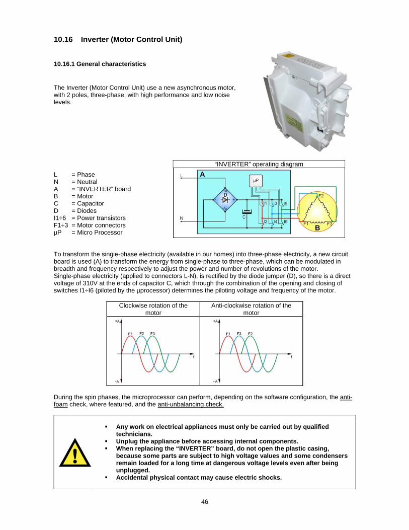
The Inverter (Motor Control Unit) use a new asynchronous motor, with 2 poles, three-phase, with high performance and low noise levels. L = Phase N = Neutral A = “INVERTER” board B = Motor C = Capacitor D = Diodes I1÷6 = Power transistors F1÷3 = Motor connectors µP = Micro Processor To transform the single-phase electricity (available in our homes) into three-phase electricity, a new circuit board is used (A) to transform the energy from single-phase to three-phase, which can be modulated in breadth and frequency respectively to adjust the power and number of revolutions of the motor. Single-phase electricity (applied to connectors L-N), is rectified by the diode jumper (D), so there is a direct voltage of 310V at the ends of capacitor C, which through the combination of the opening and closing of switches I1÷I6 (piloted by the µprocessor) determines the piloting voltage and frequency of the motor.
Clockwise rotation of the motor
Anti-clockwise rotation of the motor
During the spin phases, the microprocessor can perform, depending on the software configuration, the anti-foam check, where featured, and the anti-unbalancing check.
Any work on electrical appliances must only be carried out by qualified technicians.
Unplug the appliance before accessing internal components. When replacing the “INVERTER” board, do not open the plastic casing,
because some parts are subject to high voltage values and some condensers remain loaded for a long time at dangerous voltage levels even after being unplugged.
Accidental physical contact may cause electric shocks.
“INVERTER” operating diagram
47
10.17 Solenoid valves
10.17.1 General characteristics
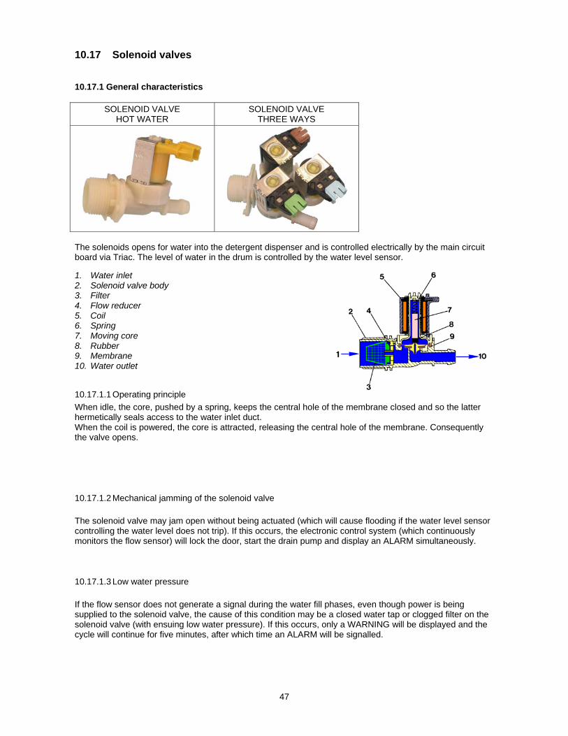
SOLENOID VALVE HOT WATER
SOLENOID VALVE THREE WAYS
The solenoids opens for water into the detergent dispenser and is controlled electrically by the main circuit board via Triac. The level of water in the drum is controlled by the water level sensor. 1. Water inlet 2. Solenoid valve body 3. Filter 4. Flow reducer 5. Coil 6. Spring 7. Moving core 8. Rubber 9. Membrane 10. Water outlet
10.17.1.1 Operating principle
When idle, the core, pushed by a spring, keeps the central hole of the membrane closed and so the latter hermetically seals access to the water inlet duct. When the coil is powered, the core is attracted, releasing the central hole of the membrane. Consequently the valve opens.
10.17.1.2 Mechanical jamming of the solenoid valve
The solenoid valve may jam open without being actuated (which will cause flooding if the water level sensor controlling the water level does not trip). If this occurs, the electronic control system (which continuously monitors the flow sensor) will lock the door, start the drain pump and display an ALARM simultaneously.
10.17.1.3 Low water pressure
If the flow sensor does not generate a signal during the water fill phases, even though power is being supplied to the solenoid valve, the cause of this condition may be a closed water tap or clogged filter on the solenoid valve (with ensuing low water pressure). If this occurs, only a WARNING will be displayed and the cycle will continue for five minutes, after which time an ALARM will be signalled.
48
10.17.1.4 Diagram
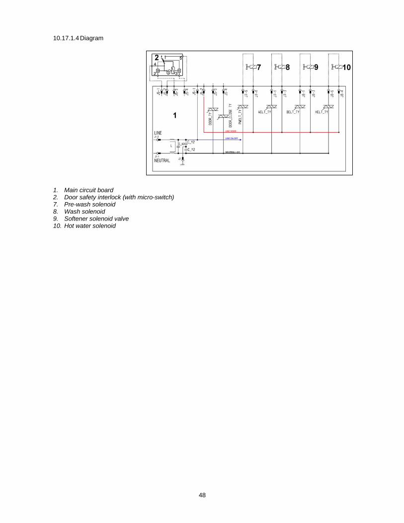
1. Main circuit board 2. Door safety interlock (with micro-switch) 7. Pre-wash solenoid 8. Wash solenoid 9. Softener solenoid valve 10. Hot water solenoid
49
10.18 Flowmeter
10.18.1 General characteristics
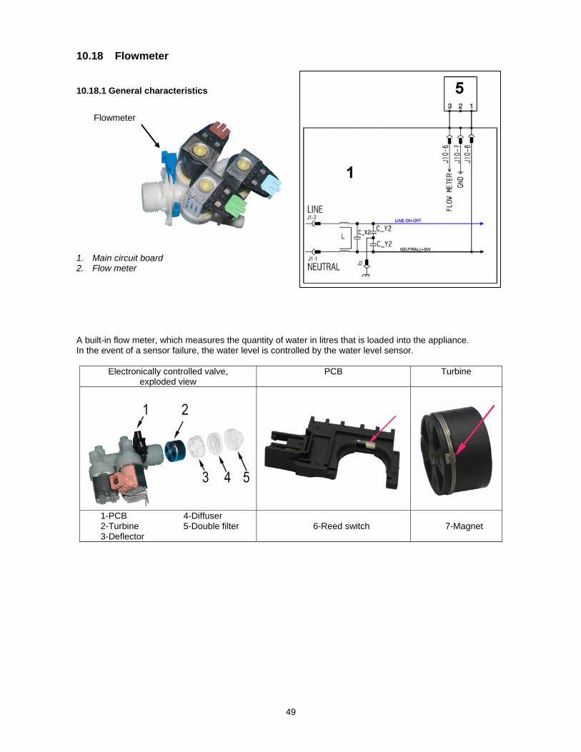
1. Main circuit board 2. Flow meter A built-in flow meter, which measures the quantity of water in litres that is loaded into the appliance. In the event of a sensor failure, the water level is controlled by the water level sensor.
Electronically controlled valve, exploded view
PCB Turbine
1-PCB 4-Diffuser 2-Turbine 5-Double filter 3-Deflector
6-Reed switch 7-Magnet
Flowmeter

50
10.18.2 Operating principle of the flowmeter
The main components of the flowmeter are: 1. Turbine (with magnet and
counterweight mounted on the outside)
2 Reed switch (normally open) 3 Magnet 4 Counterweight Water entering the solenoid valve rotates the turbine (1) and magnet (3), which passes in front of the Reed switch (2), thus closing it. As this contact opens and closes, it generates pulses (at a frequency that depends on the water flow rate). The turbine completes 230 revolutions for each litre of water. The operating range of the flow sensor is 0.2÷10 bar. Using the signal it receives, the micro-processor can calculate the number of litres of water passing through the solenoid valve.
Closed contact Open contact
Signal 0 Signal 1
51
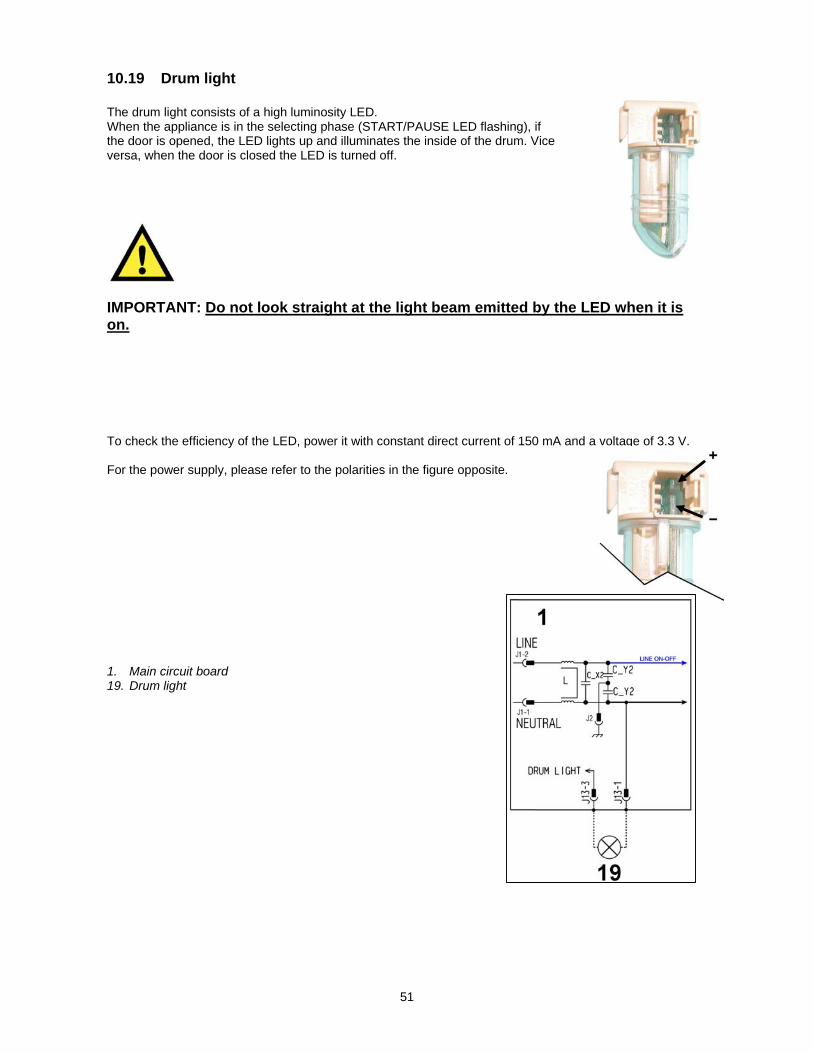
10.19 Drum light The drum light consists of a high luminosity LED. When the appliance is in the selecting phase (START/PAUSE LED flashing), if the door is opened, the LED lights up and illuminates the inside of the drum. Vice versa, when the door is closed the LED is turned off.
IMPORTANT: Do not look straight at the light beam emitted by the LED when it is on. To check the efficiency of the LED, power it with constant direct current of 150 mA and a voltage of 3.3 V. For the power supply, please refer to the polarities in the figure opposite. 1. Main circuit board 19. Drum light

52
11 ALARM SUMMARY TABLE (Note that some alarms might not be valid for your appliance) Alarm Description Possible fault Machine status/action Reset
E00
E11 Water fill difficulty during washing
Tap closed or water pressure too low; Drain pipe improperly positioned; Water fill solenoid valve faulty; Leaks from water circuit on pressure switch; Pressure switch faulty; Wiring faulty; Main PCB faulty.
Cycle is paused with door locked. START/RESET
E13 Water leaks Drain pipe improperly positioned; Water pressure too low; Water fill solenoid valve faulty; Water circuit on pressure switch is leaking/clogged; Pressure switch faulty.
Cycle is paused with door locked. START/RESET
E21 Drain difficulty during washing Drain pipe kinked/clogged/improperly positioned; Drain filter clogged/dirty; Wiring faulty; Pressure switch faulty; Drain pump rotor blocked; Drain pump faulty; Main PCB faulty.
Cycle paused (after 2 attempts).
START ON/OFF RESET
E23 Faulty triac for drain pump Wiring faulty; Drain pump faulty; Main PCB faulty. Safety drain cycle - Cycle stops with door open.
RESET
E24 Drain pump TRIAC “sensing” circuit faulty.
Main circuit board faulty. Safety drain cycle - Cycle stops with door unlocked.
RESET
E31 Malfunction in electronic water level sensor
Wiring; Faulty water level sensor; Main PCB. Cycle stops with door locked. RESET
E32 Calibration error of the electronic pressure switch
Drain pipe kinked/clogged/improperly positioned; Solenoid valve faulty; Drain filter clogged/dirty; Drain pump faulty; Leaks from pressure switch hydraulic circuit; Pressure switch faulty; Wiring; main PCB.
Cycle paused. START/RESET
E35 Overflow Water fill solenoid valve faulty; Leaks from water circuit on pressure switch; Wiring faulty; Pressure switch faulty; Main PCB faulty.
Cycle interrupted. Safety drain cycle. Drain pump continues to operate (5 min. on, then 5 min. off. etc.).
RESET
E38
Internal pressure chamber is clogged (water level does not change for at least 30 sec. of drum rotation)
Motor belt broken; Water circuit on pressure switch clogged. Heating phase is skipped. RESET
E41 Door open Check whether the door is closed properly; Wiring faulty; Door safety interlock faulty; Main circuit board faulty.
Cycle paused. START/RESET
E42 Problems with door lock Wiring faulty; Door safety interlock faulty; Electrical current leak between heating element and ground; Main PCB faulty.
Cycle paused. START/RESET
E43 Faulty triac supplying power to door delay system
Wiring faulty; Door safety interlock faulty; Main circuit board faulty.
(Safety drain cycle) Cycle blocked.
RESET
E44 Faulty sensing by door delay system
Main circuit board faulty. (Safety drain cycle)
Cycle blocked. RESET
E45 Faulty sensing by door delay system triac
Main circuit board faulty. (Safety drain cycle)
Cycle blocked. RESET
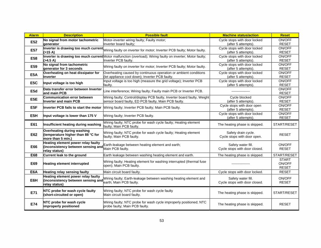
53
Alarm Description Possible fault Machine status/action Reset
E52 No signal from motor tachometric generator
Motor-inverter wiring faulty; Faulty motor; Inverter board faulty;
Cycle stops with door locked (after 5 attempts).
ON/OFF RESET
E57 Inverter is drawing too much current (>15 A)
Wiring faulty on inverter for motor; Inverter PCB faulty; Motor faulty. Cycle stops with door locked
(after 5 attempts). ON/OFF RESET
E58 Inverter is drawing too much current (>4.5 A)
Motor malfunction (overload); Wiring faulty on inverter; Motor faulty; Inverter PCB faulty.
Cycle stops with door locked (after 5 attempts).
ON/OFF RESET
E59 No signal from tachometric generator for 3 seconds
Wiring faulty on inverter for motor; Inverter PCB faulty; Motor faulty. Cycle stops with door locked
(after 5 attempts). ON/OFF RESET
E5A Overheating on heat dissipator for Inverter
Overheating caused by continuous operation or ambient conditions (let appliance cool down); Inverter PCB faulty.
Cycle stops with door locked (after 5 attempts).
ON/OFF RESET
E5C Input voltage is too high Input voltage is too high (measure the grid voltage); Inverter PCB faulty.
Cycle stops with door locked (after 5 attempts).
ON/OFF RESET
E5d Data transfer error between Inverter and main PCB
Line interference; Wiring faulty; Faulty main PCB or Inverter PCB. ---------------- ON/OFF RESET
E5E Communication error between Inverter and main PCB
Wiring faulty; Control/display PCB faulty, Inverter board faulty, Weight sensor board faulty, ED PCB faulty, Main PCB faulty.
Cycle blocked (after 5 attempts).
ON/OFF RESET
E5F Inverter PCB fails to start the motor Wiring faulty; Inverter PCB faulty; Main PCB faulty. Cycle stops with door open
(after 5 attempts). ON/OFF RESET
E5H Input voltage is lower than 175 V Wiring faulty; Inverter PCB faulty. Cycle stops with door locked
(after 5 attempts). ON/OFF RESET
E61 Insufficient heating during washing Wiring faulty; NTC probe for wash cycle faulty; Heating element faulty; Main PCB faulty.
The heating phase is skipped. START/RESET
E62 Overheating during washing (temperature higher than 88 °C for more than 5 min.)
Wiring faulty; NTC probe for wash cycle faulty; Heating element faulty; Main PCB faulty.
Safety drain cycle. Cycle stops with door open.
RESET
E66 Heating element power relay faulty (inconsistency between sensing and relay status)
Earth-leakage between heating element and earth; Main PCB faulty.
Safety water fill. Cycle stops with door closed.
ON/OFF RESET
E68 Current leak to the ground Earth leakage between washing heating element and earth. The heating phase is skipped. START/RESET
E69 Heating element interrupted Wiring faulty; Heating element for washing interrupted (thermal fuse open); Main PCB faulty.
---------------- START ON/OFF RESET
E6A Heating relay sensing faulty Main circuit board faulty. Cycle stops with door locked. RESET
E6H Heating element power relay faulty (inconsistency between sensing and relay status)
Wiring faulty; Earth-leakage between washing heating element and earth; Main PCB faulty.
Safety water fill. Cycle stops with door closed.
ON/OFF RESET
E71 NTC probe for wash cycle faulty (short-circuited or open)
Wiring faulty; NTC probe for wash cycle faulty Main circuit board faulty.
The heating phase is skipped. START/RESET
E74 NTC probe for wash cycle improperly positioned
Wiring faulty; NTC probe for wash cycle improperly positioned; NTC probe faulty; Main PCB faulty.
The heating phase is skipped. RESET
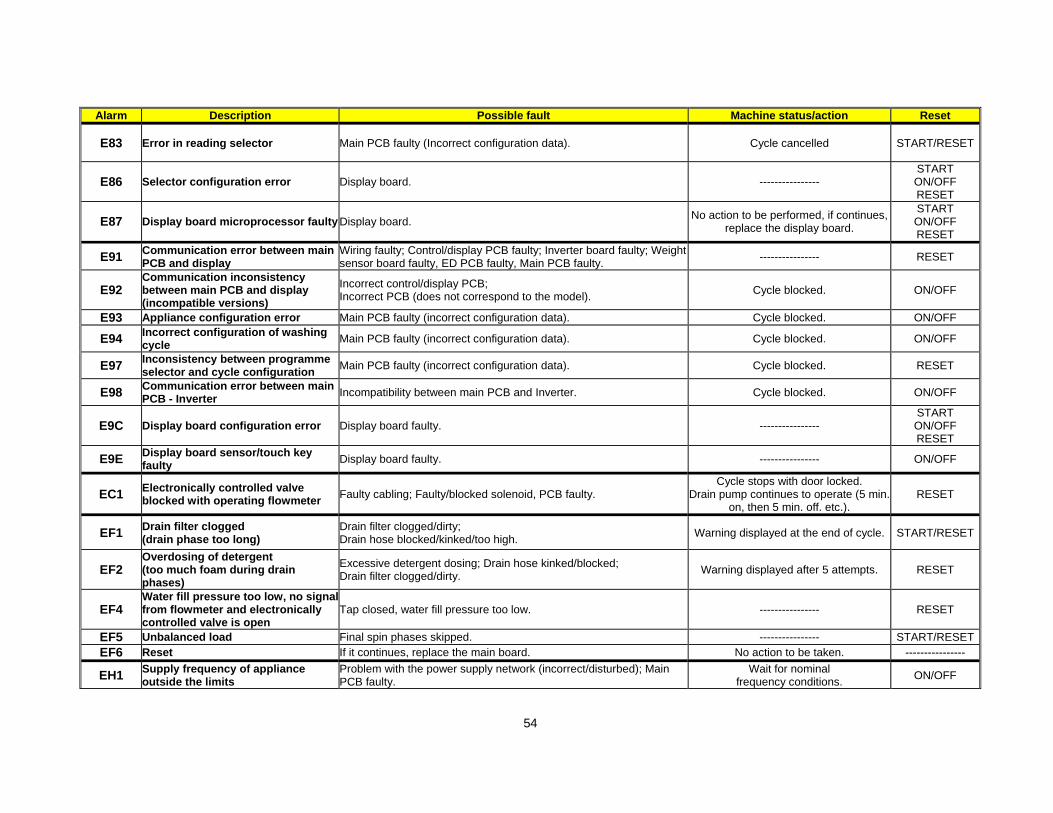
54
Alarm Description Possible fault Machine status/action Reset
E83 Error in reading selector Main PCB faulty (Incorrect configuration data). Cycle cancelled START/RESET
E86 Selector configuration error Display board. ---------------- START ON/OFF RESET
E87 Display board microprocessor faulty Display board. No action to be performed, if continues,
replace the display board.
START ON/OFF RESET
E91 Communication error between main PCB and display
Wiring faulty; Control/display PCB faulty; Inverter board faulty; Weight sensor board faulty, ED PCB faulty, Main PCB faulty.
---------------- RESET
E92 Communication inconsistency between main PCB and display (incompatible versions)
Incorrect control/display PCB; Incorrect PCB (does not correspond to the model). Cycle blocked. ON/OFF
E93 Appliance configuration error Main PCB faulty (incorrect configuration data). Cycle blocked. ON/OFF
E94 Incorrect configuration of washing cycle
Main PCB faulty (incorrect configuration data). Cycle blocked. ON/OFF
E97 Inconsistency between programme selector and cycle configuration
Main PCB faulty (incorrect configuration data). Cycle blocked. RESET
E98 Communication error between main PCB - Inverter
Incompatibility between main PCB and Inverter. Cycle blocked. ON/OFF
E9C Display board configuration error Display board faulty. ---------------- START ON/OFF RESET
E9E Display board sensor/touch key faulty
Display board faulty. ---------------- ON/OFF
EC1 Electronically controlled valve blocked with operating flowmeter
Faulty cabling; Faulty/blocked solenoid, PCB faulty. Cycle stops with door locked.
Drain pump continues to operate (5 min. on, then 5 min. off. etc.).
RESET
EF1 Drain filter clogged (drain phase too long)
Drain filter clogged/dirty; Drain hose blocked/kinked/too high.
Warning displayed at the end of cycle. START/RESET
EF2 Overdosing of detergent (too much foam during drain phases)
Excessive detergent dosing; Drain hose kinked/blocked; Drain filter clogged/dirty.
Warning displayed after 5 attempts. RESET
EF4 Water fill pressure too low, no signalfrom flowmeter and electronically controlled valve is open
Tap closed, water fill pressure too low. ---------------- RESET
EF5 Unbalanced load Final spin phases skipped. ---------------- START/RESET
EF6 Reset If it continues, replace the main board. No action to be taken. ----------------
EH1 Supply frequency of appliance outside the limits
Problem with the power supply network (incorrect/disturbed); Main PCB faulty.
Wait for nominal frequency conditions.
ON/OFF
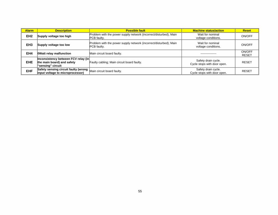
55
Alarm Description Possible fault Machine status/action Reset
EH2 Supply voltage too high Problem with the power supply network (incorrect/disturbed); Main PCB faulty.
Wait for nominal voltage conditions.
ON/OFF
EH3 Supply voltage too low Problem with the power supply network (incorrect/disturbed); Main PCB faulty.
Wait for nominal voltage conditions.
ON/OFF
EH4 0Watt relay malfunction Main circuit board faulty. ---------------- ON/OFF RESET
EHE Inconsistency between FCV relay (in the main board) and safety “sensing” circuit
Faulty cabling; Main circuit board faulty. Safety drain cycle.
Cycle stops with door open. RESET
EHF Safety sensing circuit faulty (wrong input voltage to microprocessor)
Main circuit board faulty. Safety drain cycle.
Cycle stops with door open. RESET

56
11.1 Alarm codes for appliance with external liquid supply system
Alarm code
Alarm description Fault condition Possible fault Machine
action/statusReset key
E9A DET_DOSING_ABS_AL External liquid supply system configured but communication failure (before payment).
Wiring defective External liquid supply system defective
MB defective No power supply to sat
Cycle blocked OFF/ON
EF9 DET_DOSING_COM_AL External liquid supply system configured but communication failure (after payment).
Wiring defective External liquid supply system defective
MB defective No or wrong power supply to sat
No actions OFF/ON
11.2 Detailed description of alarm codes
11.2.1 E9A - External liquid supply system configured but communication failure (before payment)
The user has not yet paid and there are communication problems in between External liquid supply system board and Motherboard. Problems could be due to Hardware (problems on connectors for example disconnection, on satellite or mother board), due to disturbs (burst on wiring) or satellite unplugged from power supply. The alarm appears after 5 seconds of missing communication after which the communication is interrupted for 35 seconds. Then the Motherboard retries to restore the connection and, if the problem remains, disconnects again. This alarm is displayed on the user interface using the format “E” + “9”(alarm family digit) + “0”. When the alarm is set the machine is blocked. To clear the alarm is necessary to switch off the machine.
11.2.2 EF9 — External liquid supply system configured but communication failure (after payment)
The user has already paid and there are communication problems in between External liquid supply system board and Motherboard. Problems could be due to Hardware (problems on connectors for example disconnection, on satellite or mother board), due to disturbs (burst on wiring) or satellite unplugged from power supply. The alarm appears after 5 seconds of missing communication after which the communication is interrupted for 35 seconds. Then the Motherboard retries to restore the connection and, if the problem remains, disconnects again. The alarm is not displayed. No action is executed when alarm is detected. To clear the alarm is necessary to switch off the machine.

Technical Support - DMM 57/80 599 74 98-60 Rev.00
12 ACCESSIBILITY
12.1 Worktop Remove the screws that secure it to the back panel. Pull it out from the back.
12.2 From the worktop, you can access 1. Main board 2. Solenoid valves 3. Control panel 4. Display board/light diffuser/buttons/buttons springs assembly 5. Electronic water level sensor 6. Detergent container 7. Detergent fill pipe 8. Upper counterweight
12.2.1 Main board
Remove the worktop. Unfasten the three screws securing it to the cabinet. Move it in the direction of the dotted arrow. Place the wiring behind the hook securing the board to the back panel. Remove the wiring from the side hook of the board protection.
12
3 4
5 6
78

Technical Support - DMM 58/80 599 74 98-60 Rev.00
Remove the wiring from the central hook. Remove the main board. Turn it. Disconnect the hooks fixing the connector protection on one side then the other.
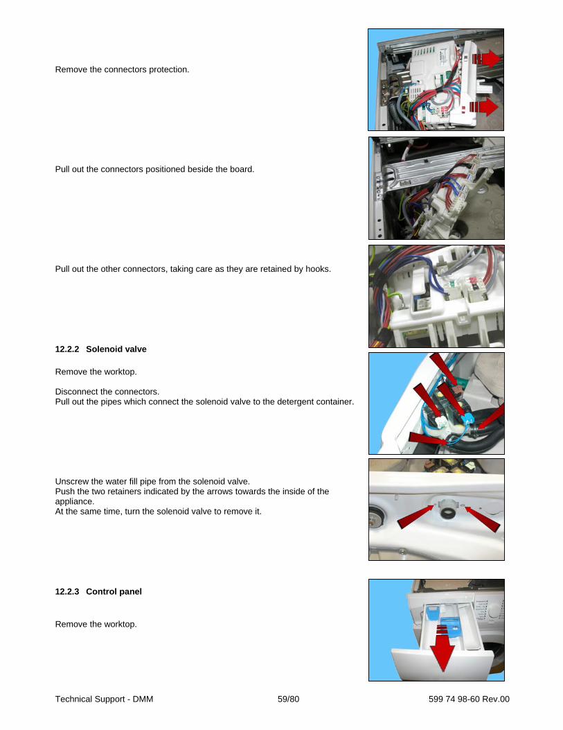
Technical Support - DMM 59/80 599 74 98-60 Rev.00
Remove the connectors protection. Pull out the connectors positioned beside the board. Pull out the other connectors, taking care as they are retained by hooks.
12.2.2 Solenoid valve
Remove the worktop. Disconnect the connectors. Pull out the pipes which connect the solenoid valve to the detergent container. Unscrew the water fill pipe from the solenoid valve. Push the two retainers indicated by the arrows towards the inside of the appliance. At the same time, turn the solenoid valve to remove it.
12.2.3 Control panel
Remove the worktop.

Technical Support - DMM 60/80 599 74 98-60 Rev.00
Pull the detergent container out and at the same time press the stop locking it in place. Loosen the screws that attach the control panel to the detergent tray. Pull out the clamp from the crosspiece. Remove the four screws which secure the crosspiece to the cabinet. Remove the screws which secure the crosspiece to the detergent container. Release the anchor tab which secures the detergent container to the crosspiece. Raise both sides of the control panel so as to pull out the hooks which secure it to the front panel.
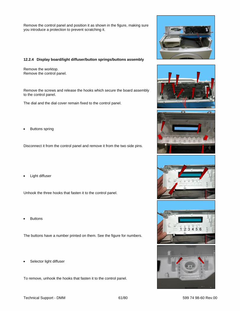
Technical Support - DMM 61/80 599 74 98-60 Rev.00
Remove the control panel and position it as shown in the figure, making sure you introduce a protection to prevent scratching it.
12.2.4 Display board/light diffuser/button springs/buttons assembly
Remove the worktop. Remove the control panel. Remove the screws and release the hooks which secure the board assembly to the control panel. The dial and the dial cover remain fixed to the control panel. Buttons spring Disconnect it from the control panel and remove it from the two side pins. Light diffuser Unhook the three hooks that fasten it to the control panel. Buttons The buttons have a number printed on them. See the figure for numbers. Selector light diffuser To remove, unhook the hooks that fasten it to the control panel.

Technical Support - DMM 62/80 599 74 98-60 Rev.00
When reassembling the display board assembly and the control panel. Remove the dial from the dial cover. Release the hooks that fasten them together, and fasten the whole to the control panel. Illustration of the dial and the dial cover. Thread the dial onto the selector pin. Insert the display board in its seat in the control panel. Insert the dial cover. If the two earth wires connecting the front panel have been disconnected, reconnect them to the fasteners of the control panel crosspiece.

Technical Support - DMM 63/80 599 74 98-60 Rev.00
12.2.5 Water level sensor
Remove the worktop. Remove the connector. Pull out the small tube which connects it to the pressure chamber. Tighten the two tabs which secure it to the cabinet and remove it.
12.2.6 Detergent container
Remove the worktop. Remove the control panel. Pull out the pipes that connect it to the solenoid valves (cold water and hot water). Unfasten the two screws securing it to the central crosspiece. Unfasten the screw in the clamp that fixes the detergent loading pipe to the tray, and remove it from its housing. Remove the detergent container.
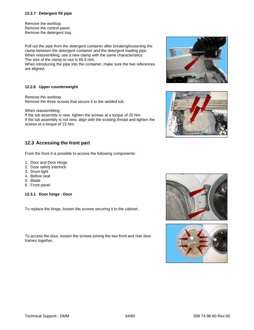
Technical Support - DMM 64/80 599 74 98-60 Rev.00
12.2.7 Detergent fill pipe
Remove the worktop. Remove the control panel. Remove the detergent tray. Pull out the pipe from the detergent container after breaking/loosening the clamp between the detergent container and the detergent loading pipe. When reassembling, use a new clamp with the same characteristics. The size of the clamp to use is 65.5 mm. When introducing the pipe into the container, make sure the two references are aligned.
12.2.8 Upper counterweight
Remove the worktop. Remove the three screws that secure it to the welded tub. When reassembling: If the tub assembly is new, tighten the screws at a torque of 20 Nm. If the tub assembly is not new, align with the existing thread and tighten the screws at a torque of 15 Nm.
12.3 Accessing the front part From the front it is possible to access the following components: 1. Door and Door Hinge 2. Door safety interlock 3. Drum light 4. Bellow seal 5. Blade 6. Front panel
12.3.1 Door hinge - Door
To replace the hinge, loosen the screws securing it to the cabinet. To access the door, loosen the screws joining the two front and rear door frames together.
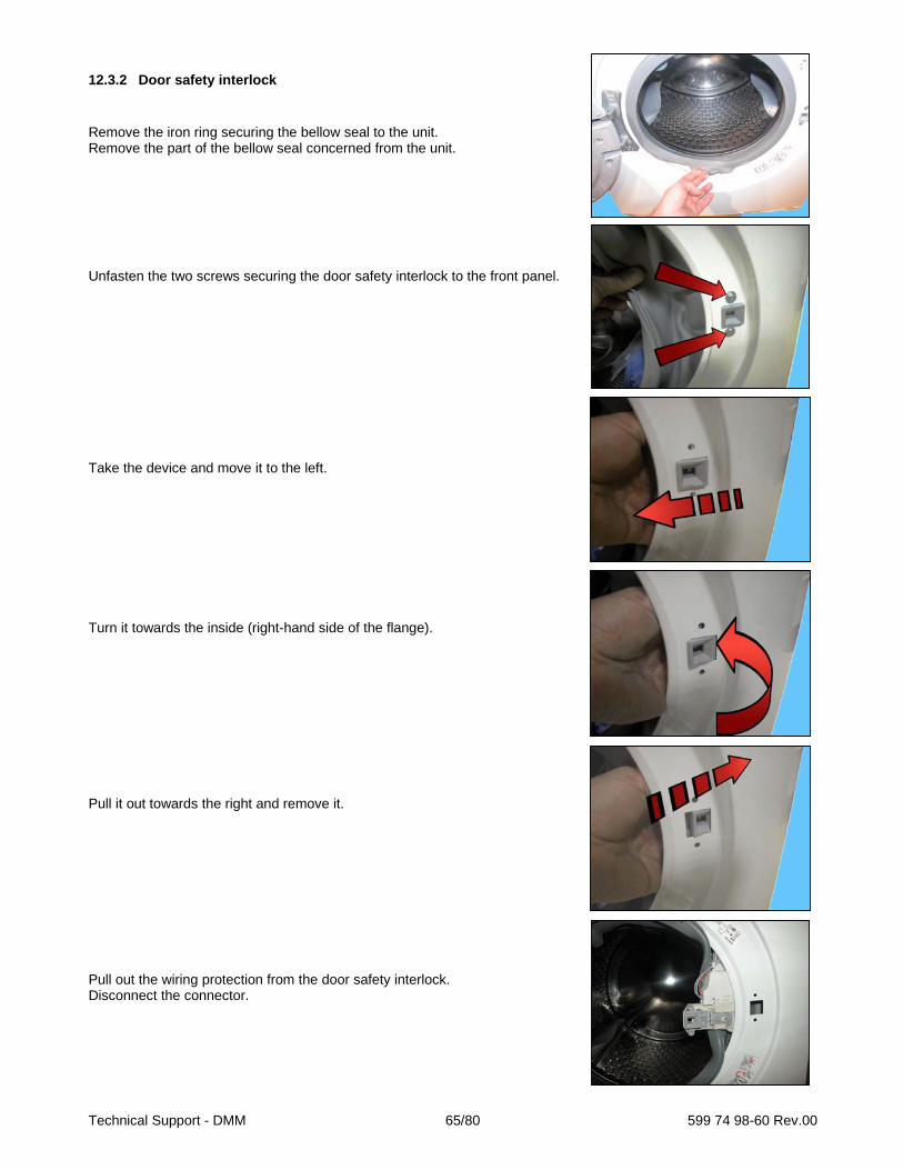
Technical Support - DMM 65/80 599 74 98-60 Rev.00
12.3.2 Door safety interlock
Remove the iron ring securing the bellow seal to the unit. Remove the part of the bellow seal concerned from the unit. Unfasten the two screws securing the door safety interlock to the front panel. Take the device and move it to the left. Turn it towards the inside (right-hand side of the flange). Pull it out towards the right and remove it. Pull out the wiring protection from the door safety interlock. Disconnect the connector.
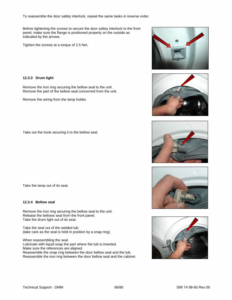
Technical Support - DMM 66/80 599 74 98-60 Rev.00
To reassemble the door safety interlock, repeat the same tasks in reverse order. Before tightening the screws to secure the door safety interlock to the front panel, make sure the flange is positioned properly on the outside as indicated by the arrows. Tighten the screws at a torque of 2.5 Nm.
12.3.3 Drum light
Remove the iron ring securing the bellow seal to the unit. Remove the part of the bellow seal concerned from the unit. Remove the wiring from the lamp holder. Take out the hook securing it to the bellow seal. Take the lamp out of its seat.
12.3.4 Bellow seal
Remove the iron ring securing the bellow seal to the unit. Release the bellows seal from the front panel. Take the drum light out of its seat. Take the seal out of the welded tub (take care as the seal is held in position by a snap ring). When reassembling the seal. Lubricate with liquid soap the part where the tub is inserted. Make sure the references are aligned. Reassemble the snap ring between the door bellow seal and the tub. Reassemble the iron ring between the door bellow seal and the cabinet.

Technical Support - DMM 67/80 599 74 98-60 Rev.00
12.3.5 Blade
This blade is secured to the drum with slides and secured with blades carved into the drum. To remove it from the drum: Insert a flat-tip screwdriver into the central slot of the left row. The screwdriver with the handle tilted towards the right push the left-hand tab down. The screwdriver with the handle tilted towards the left. Push the right-hand tab down. When the two tabs are down. Move the blade towards the front of the drum, and if necessary squash the blade at the two ends.

Technical Support - DMM 68/80 599 74 98-60 Rev.00
Before securing the new blade insert a screwdriver beneath the tabs and raise them a little. Position the new blade inside the drum guides. Push it towards the back. Insert the screwdriver (in the central slot of the left-hand row) at a right angle to the blade, so as to position it at the centre of the two drum tabs. Tilt it towards the right so that the left tab moves upwards. With the screwdriver still inserted in the slot. Tilt it towards the left so that the right tab moves upwards. With the tabs raised, the blade is secured to the drum.

Technical Support - DMM 69/80 599 74 98-60 Rev.00
12.3.6 Front panel
Remove the worktop. Remove the control panel. Remove the iron ring and remove the door bellow seal from the front panel. Unfasten the screws securing the door safety interlock. Open the filter flap and remove it. Loosen the two screws that secure the plinth to the front. Release the two hooks that secure it to the front (indicated by the arrows). Remove the plinth by turning it downwards in order to pull out the pins that secure it to the lower part of the front panel. Loosen the screws that secure the lower part of the front panel to the cabinet casing. Release the cable clamp secured to the centre of the front panel (where the lamp is featured). Unfasten the four screws securing the front panel to the sides (indicated by the arrows). Remove the front panel.
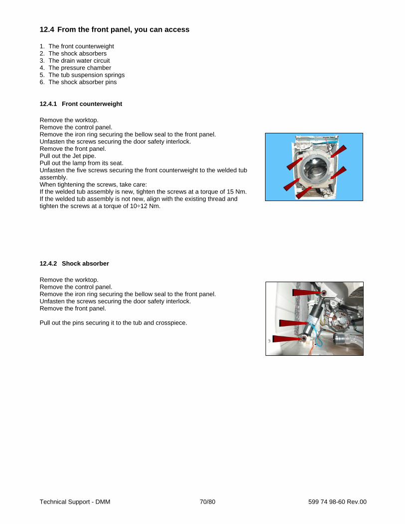
Technical Support - DMM 70/80 599 74 98-60 Rev.00
12.4 From the front panel, you can access 1. The front counterweight 2. The shock absorbers 3. The drain water circuit 4. The pressure chamber 5. The tub suspension springs 6. The shock absorber pins
12.4.1 Front counterweight
Remove the worktop. Remove the control panel. Remove the iron ring securing the bellow seal to the front panel. Unfasten the screws securing the door safety interlock. Remove the front panel. Pull out the Jet pipe. Pull out the lamp from its seat. Unfasten the five screws securing the front counterweight to the welded tub assembly. When tightening the screws, take care: If the welded tub assembly is new, tighten the screws at a torque of 15 Nm. If the welded tub assembly is not new, align with the existing thread and tighten the screws at a torque of 10÷12 Nm.
12.4.2 Shock absorber
Remove the worktop. Remove the control panel. Remove the iron ring securing the bellow seal to the front panel. Unfasten the screws securing the door safety interlock. Remove the front panel. Pull out the pins securing it to the tub and crosspiece.
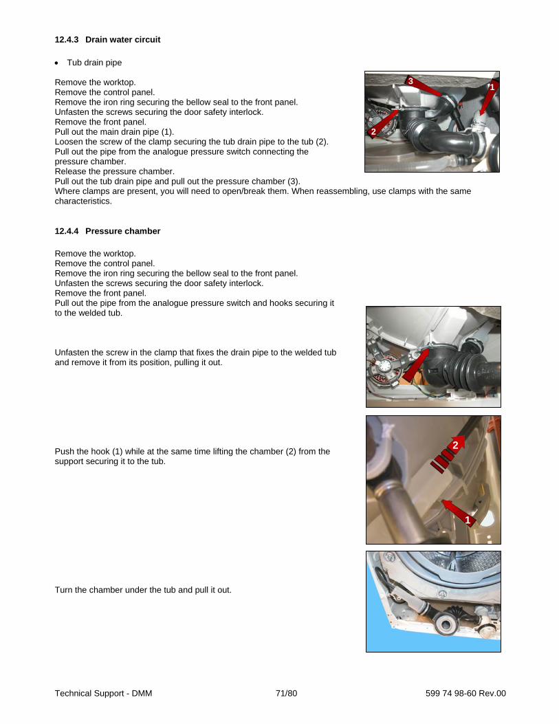
Technical Support - DMM 71/80 599 74 98-60 Rev.00
12.4.3 Drain water circuit
Tub drain pipe Remove the worktop. Remove the control panel. Remove the iron ring securing the bellow seal to the front panel. Unfasten the screws securing the door safety interlock. Remove the front panel. Pull out the main drain pipe (1). Loosen the screw of the clamp securing the tub drain pipe to the tub (2). Pull out the pipe from the analogue pressure switch connecting the pressure chamber. Release the pressure chamber. Pull out the tub drain pipe and pull out the pressure chamber (3). Where clamps are present, you will need to open/break them. When reassembling, use clamps with the same characteristics.
12.4.4 Pressure chamber
Remove the worktop. Remove the control panel. Remove the iron ring securing the bellow seal to the front panel. Unfasten the screws securing the door safety interlock. Remove the front panel. Pull out the pipe from the analogue pressure switch and hooks securing it to the welded tub. Unfasten the screw in the clamp that fixes the drain pipe to the welded tub and remove it from its position, pulling it out. Push the hook (1) while at the same time lifting the chamber (2) from the support securing it to the tub. Turn the chamber under the tub and pull it out.
1
1
1
2
3
2
1

Technical Support - DMM 72/80 599 74 98-60 Rev.00
Make a note of the latch and hook with which it is secured to the tub. If the hook securing the chamber to the welded tub is broken. Use the eyelet (indicated by the red arrow). Use a screw Code 405 50 33-52/8 (AF/2P 5x16 TE/SP must have a maximum length of 16 mm and without a tip to avoid perforating the tub), secure the chamber to the tub as shown by the arrow in the photo. When repositioning the pressure chamber in the tub drain pipe, pay attention to the references. The size of the clamp to use is 52.5 mm. When reassembling the pressure chamber, reposition the pipe connecting the pressure switch so that it never actually touches the cabinet. Filter body Remove the worktop. Remove the control panel. Remove the iron ring securing the bellow seal to the front panel. Unfasten the screws securing the door safety interlock. Remove the front panel. Loosen the screws securing it to the front crossbar (1). Pull out the main drain pipes (2) and circulation pump connection pipe. Raise it to remove the support inserted in the side crossbar (3). Remove the pump protection. Drain pump Release the connectors. Move the lock catch with some pliers (take care not to break it). Turn and pull out the pump. If the lock catch securing the pump to the filter body breaks. Secure the pump to the filter body, securing it in place using a screw, screwing the latter in the slot shown by the arrow. Size of the screw 3.5x19 Code 5024 79 51- 00/2.
2
11
2
2
3
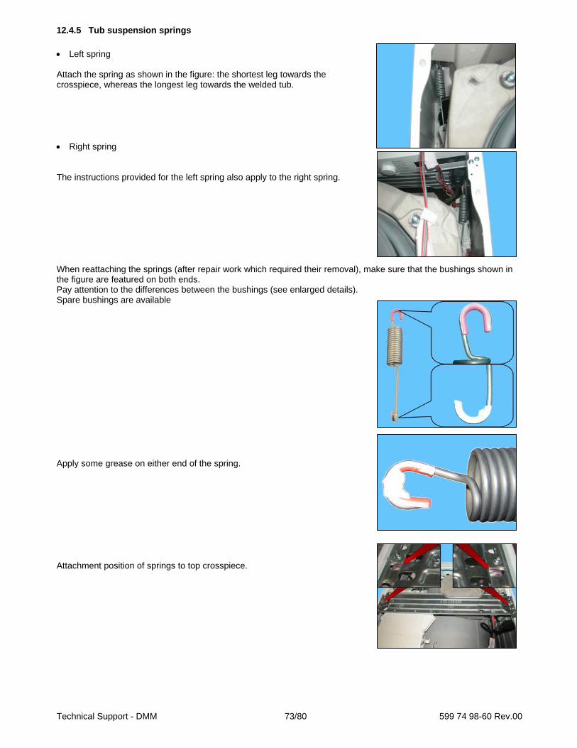
Technical Support - DMM 73/80 599 74 98-60 Rev.00
12.4.5 Tub suspension springs
Left spring Attach the spring as shown in the figure: the shortest leg towards the crosspiece, whereas the longest leg towards the welded tub. Right spring The instructions provided for the left spring also apply to the right spring. When reattaching the springs (after repair work which required their removal), make sure that the bushings shown in the figure are featured on both ends. Pay attention to the differences between the bushings (see enlarged details). Spare bushings are available Apply some grease on either end of the spring. Attachment position of springs to top crosspiece.

Technical Support - DMM 74/80 599 74 98-60 Rev.00
12.4.6 Shock absorber pin
There is a bushing on either end of the shock absorber. It has a wider profile on one end to avoid it becoming dislodged when the pin is inserted (see the two figures below).
When positioning the shock absorber inside the fastening (situated at the bottom of the cabinet or in the tub), take care when positioning the bushing, so as to insert the pin from the part of the bushing with the widest profile.
If you are having difficulty inserting the pin, grease it a little.
Narrow edge Wide edge
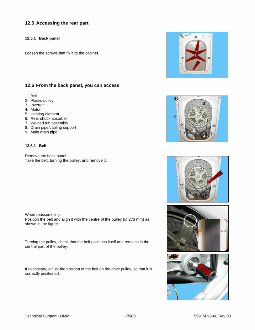
Technical Support - DMM 75/80 599 74 98-60 Rev.00
12.5 Accessing the rear part
12.5.1 Back panel
Loosen the screws that fix it to the cabinet.
12.6 From the back panel, you can access 1. Belt 2. Plastic pulley 3. Inverter 4. Motor 5. Heating element 6. Rear shock absorber 7. Welded tub assembly 8. Drain pipe/cabling support 9. Main drain pipe
12.6.1 Belt
Remove the back panel. Take the belt, turning the pulley, and remove it. When reassembling: Position the belt and align it with the centre of the pulley ( 273 mm) as shown in the figure. Turning the pulley, check that the belt positions itself and remains in the central part of the pulley. If necessary, adjust the position of the belt on the drive pulley, so that it is correctly positioned.
1
2
34
5
6
7
8
9
10
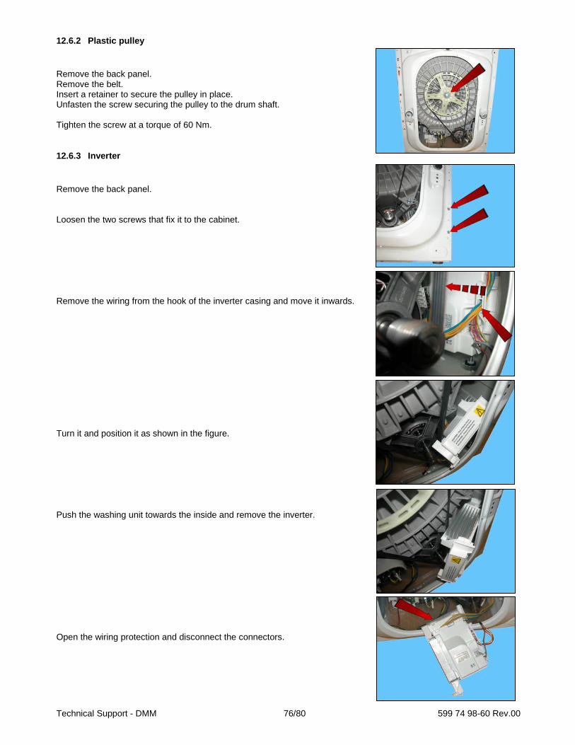
Technical Support - DMM 76/80 599 74 98-60 Rev.00
12.6.2 Plastic pulley
Remove the back panel. Remove the belt. Insert a retainer to secure the pulley in place. Unfasten the screw securing the pulley to the drum shaft. Tighten the screw at a torque of 60 Nm.
12.6.3 Inverter
Remove the back panel. Loosen the two screws that fix it to the cabinet. Remove the wiring from the hook of the inverter casing and move it inwards. Turn it and position it as shown in the figure. Push the washing unit towards the inside and remove the inverter. Open the wiring protection and disconnect the connectors.

Technical Support - DMM 77/80 599 74 98-60 Rev.00
When repositioning the inverter in its seat, pay attention that the hook is inserted in its position in the crosspiece.
12.6.4 Motor
Remove the back panel. Remove the belt. Disconnect the connectors: for the power supply and earthing. Loosen the two front fastening screws (1) and the rear ones (2). When reassembling, restore the connections. If the clamp securing the wiring to the motor breaks, replace it with a new one. Tighten the screws at a torque of 5 Nm.
12.6.5 Heating element
Remove the back panel. Disconnect the connectors of the heating element (1) and NTC probe (2). Loosen the nut (3) and pull it out. Tighten the nut at a torque of 4 Nm.
12.6.6 Rear shock absorber
Remove the back panel. To take the pins out of their seats, push the locking tooth and at the same time remove it with pliers. Perform the same operations for the other pin. Take the shock absorber out.
1
1
2
1 1
2 3

Technical Support - DMM 78/80 599 74 98-60 Rev.00
12.6.7 Welded tub assembly
Remove the worktop. Remove the control panel. Remove the front panel. Remove the detergent tray. Remove the upper counterweight. Remove the front counterweight. Remove the back panel. To remove the washing unit assembly, disconnect: All the tub pipes, the wiring connectors that connect the heating element, the NTC probe, remove the belt and the motor (to lighten the tub). Lay the appliance on its back (making sure you place a polystyrene or cardboard layer on the floor to prevent damaging the cabinet). Take the tub out of the washing machine.
12.6.8 Drain pipe/cabling support
When fixing the drain pipe/cabling support make sure that the two stops (indicated by the red arrows) fit into their housings, locking the support to the unit. If the fixing is not stable and there is a risk of it coming out of its position, fasten the support to the unit with a screw (6.5x 3.5 mm) screwed into the hole indicated by the blue arrow.
12.6.9 Main drain pipe
Arrange the drain pipe as shown in the figures.
1
2
3
4
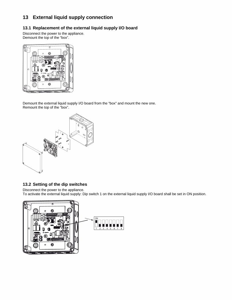
13 External liquid supply connection
13.1 Replacement of the external liquid supply I/O board Disconnect the power to the appliance. Demount the top of the “box”.
Demount the external liquid supply I/O board from the “box” and mount the new one. Remount the top of the “box”.
13.2 Setting of the dip switches Disconnect the power to the appliance. To activate the external liquid supply: Dip switch 1 on the external liquid supply I/O board shall be set in ON position.
ON
1 2 3 4 5 6 7 8

13.3 Uninstall the external liquid supply Disconnect the power to the appliance. To deactivate the external liquid supply: The dip switches on the external liquid supply I/O board shall be set in OFF position.
ON
1 2 3 4 5 6 7 8
13.4 Pump signal schedule Signal/Pump Chemical Used in Program Other info1 Detergent Pre wash and main
wash
2 Bleach Main wash Normal 60 and 95 Eco 60 Disinfection 60, 70 and 85
3 Softener Last rinse All programs except Mop 60 and 85 and Rinse
Can be deselected by the user with option button
4 Floor care Last rinse Mop 60 and 85 Rinse

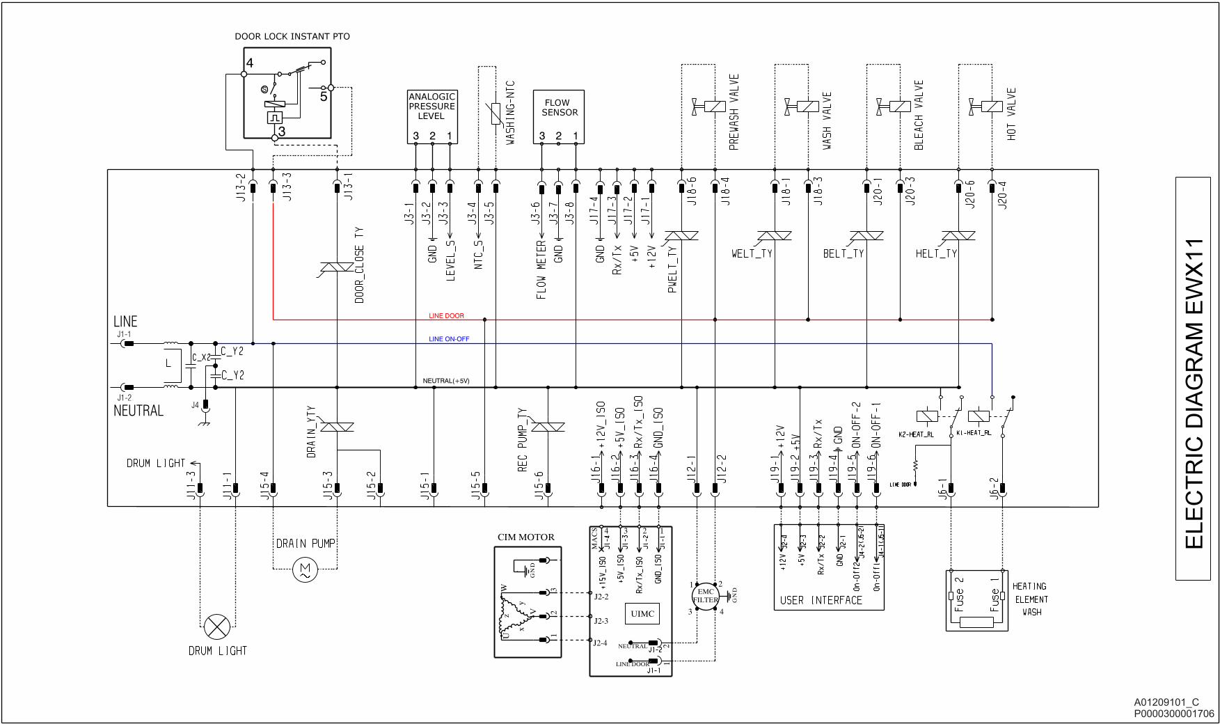

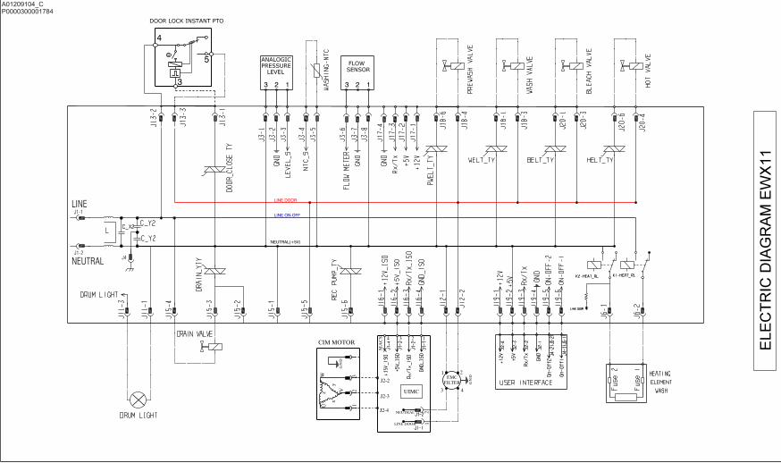

www.electrolux.com/myPro