428 604381/2021/o/o ped/ti/rdso कर्षण संस्थापन ननदेशाऱय
TRANSCRIPT

Specification No. TI/SPC/PSI/AUTOTR/0091 Page 1 of 50
कर्षण संस्थापन ननदेशाऱय
TRACTION INSTALLATION DIRECTORATE
भारत सरकार, रेऱ मंत्राऱय
GOVERNMENT OF INDIA
MINISTRY OF RAILWAYS
TECHNICAL SPECIFICATION FOR
50MVA, 75MVA & 150MVA
220/132kV THREE- PHASE OIL IMMERSED TYPE AUTO TRANSFORMER
Specification No. TI/SPC/PSI/AUTOTR/0091
MM/YYYY
ISSUED BY
_____________________________________________________________ TRACTION INSTALLATION DIRECTORATE
RESEARCH DESIGNS AND STANDARDS ORGANISATION
(MINISTRY OF RAILWAYS) MANAK NAGAR, LUCKNOW-226 011
_______________________________________________________
604381/2021/O/o PED/TI/RDSO428

Specification No. TI/SPC/PSI/AUTOTR/0091 Page 2 of 50
Specification for 50/75/150MVA, ONAN/ONAF/OFAF, 220kV/132kV
Three- Phase Oil Immersed Type Auto Transformer
Specification No. TI/SPC/PSI/AUTOTR/0091
Amendment number
Amendment /Revision Total pages (including annexure)
Date of issue
0 Specification no. TI/SPC/PSI/AUTOTR/0091 Revised
48
Prepared by Checked by Approved by
Signature
Date
Designation
604381/2021/O/o PED/TI/RDSO429
Specification No. TI/SPC/PSI/AUTOTR/0091 Page 3 of 50
INDEX
SL. No. Item Page No
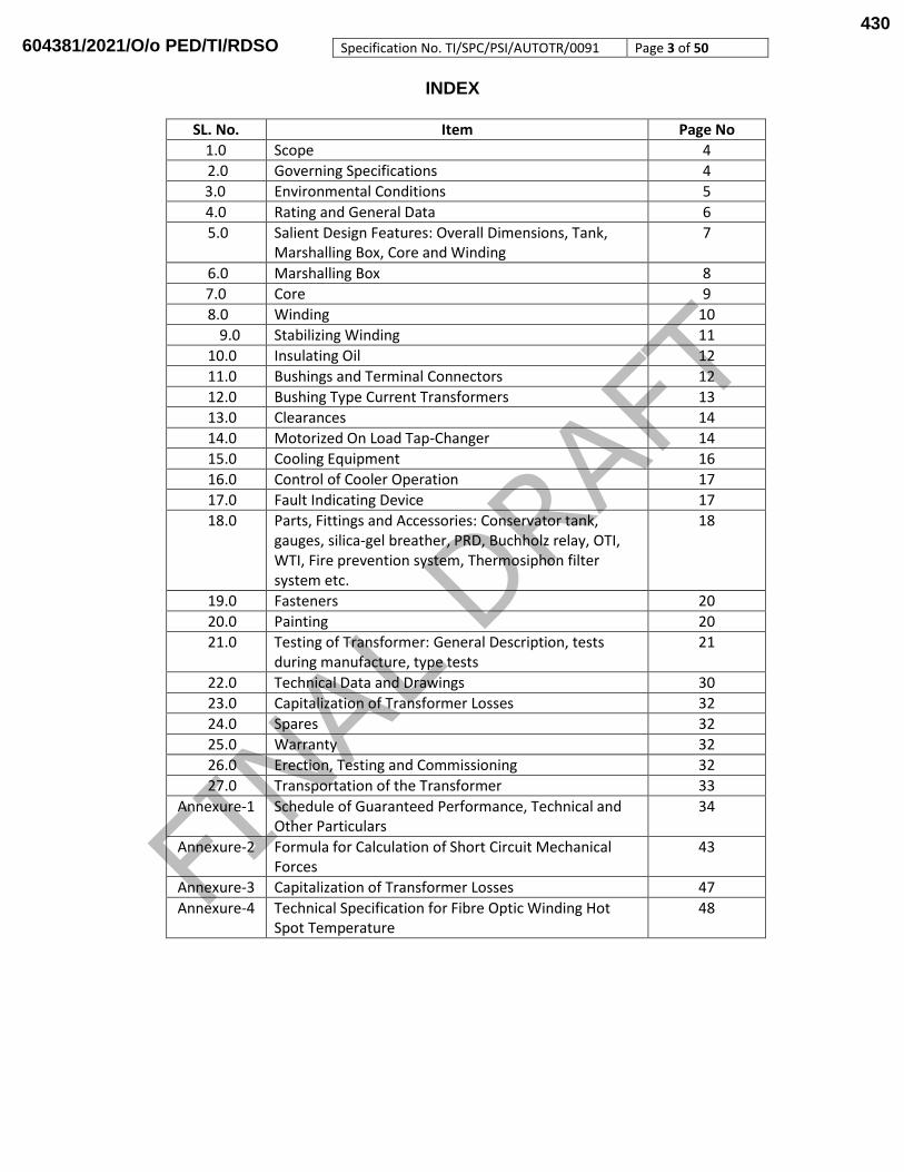
1.0 Scope 4
2.0 Governing Specifications 4
3.0 Environmental Conditions 5
4.0 Rating and General Data 6
5.0 Salient Design Features: Overall Dimensions, Tank, Marshalling Box, Core and Winding
7
6.0 Marshalling Box 8
7.0 Core 9
8.0 Winding 10
9.0 Stabilizing Winding 11
10.0 Insulating Oil 12
11.0 Bushings and Terminal Connectors 12
12.0 Bushing Type Current Transformers 13
13.0 Clearances 14
14.0 Motorized On Load Tap-Changer 14
15.0 Cooling Equipment 16
16.0 Control of Cooler Operation 17
17.0 Fault Indicating Device 17
18.0 Parts, Fittings and Accessories: Conservator tank, gauges, silica-gel breather, PRD, Buchholz relay, OTI, WTI, Fire prevention system, Thermosiphon filter system etc.
18
19.0 Fasteners 20
20.0 Painting 20
21.0 Testing of Transformer: General Description, tests during manufacture, type tests
21
22.0 Technical Data and Drawings 30
23.0 Capitalization of Transformer Losses 32
24.0 Spares 32
25.0 Warranty 32
26.0 Erection, Testing and Commissioning 32
27.0 Transportation of the Transformer 33
Annexure-1 Schedule of Guaranteed Performance, Technical and Other Particulars
34
Annexure-2 Formula for Calculation of Short Circuit Mechanical Forces
43
Annexure-3 Capitalization of Transformer Losses 47
Annexure-4 Technical Specification for Fibre Optic Winding Hot Spot Temperature
48
604381/2021/O/o PED/TI/RDSO430

Specification No. TI/SPC/PSI/AUTOTR/0091 Page 4 of 50
1.0 SCOPE
1.1 This specification supersedes the specification no. TI/SPC/PSI/AUTOTR/0090 (12/09).
1.2 It is to be noted that “The Make in India Policy of Government of India shall be applicable.”
1.3 This specification covers design, manufacture, assembly, testing at manufacturer’s works, supply and commissioning of 50MVA, 75MVA, 150MVA 220/132kV three phase oil immersed type auto transformer for effectively earthed system.
1.4 RDSO’s ISO requirement:
All the provisions contained in RDSO’s ISO procedures laid down in Document No. - QO-D-8.1-11 (Titled “Vendor-changes in approval status”) and subsequent versions/amendments thereof shall be binding and applicable on the successful vendor/vendors in the contracts floated by Railways to maintain quality of products supplied to Railways.
1.5 The transformers shall have weight and dimensions suitable for transport either on Railways to destination or by Road to Railways destination. The assembly and placement of transformers on foundations shall also be included in the scope. The power supply for cooling system is to be obtained from a single phase 25 kV/230 V, 100 kVA auxiliary transformers connected with traction overhead lines. In normal conditions voltage available shall be 220+ 10%, but due to fluctuations in 25 kV supplies, LT supply may also vary from 150 V to 280 V. The manufacturer should ensure satisfactory operation of motors during above voltage conditions.
1.6 The transformer shall be complete with all parts, fittings and accessories necessary for its efficient operation in the unattended traction substation. All such parts, fittings and accessories shall be deemed to be within the scope of this specification, whether specifically mentioned herein or not. It is the responsibility of the transformer manufacturer to comply the complete specification including for the accessories.
2.0 GOVERNING SPECIFICATION
2.1 For the purpose of this specification, following standards and codes of practices (latest version), and Indian Electricity Rules are included, wherever applicable.
1 IS:5 Colours for Ready Mixed Paints and Enamels
2 ISO/EN12944 Protective Paint Systems.
3 IS:1554(part-I) PVC insulated (Heavy duty) electric cables for working voltages upto and including 1100 volts.
4 IS:1570 (Part-V) Stainless and heat resisting steels.
5 IS:1576 Solid pressboard for electrical purposes.
6 IS:1866 Code of practice for maintenance and supervision of mineral insulating oil in equipment.
7 IS:2026 Power transformers.
8 IS/IEC: 60137 Bushing for alternating voltages above 1000 volts.
9 IS:2705/16227 Current transformers.
10 IS:2927 Brazing alloys.
11 IS:3024 Grain Oriented Electrical Steel Sheet and Strip.
12 IS:3637 Gas operated relays.
13 IS:3639 Fittings and accessories for power transformers.
14 IS:4253 Specification for Cork Composition Sheets.
15 IS:5561 Specification for Electric Power Connectors.
16 IS:5621 Hollow insulators for use in electrical equipment.
604381/2021/O/o PED/TI/RDSO431

Specification No. TI/SPC/PSI/AUTOTR/0091 Page 5 of 50
17 IS:5728 Guide for shot- circuit calculations.
18 IS:6209 Methods for partial discharge measurements.
19 IS:6600 Guide for loading of oil - immersed transformers.
20 IS:8468 On load tap changers.
21 IS:10028 Code of practice for selection, installation and maintenance of transformers.
22 IS:10593 Method of evaluating the analysis of gases in oil- filled electrical equipment in service.
23 IS:12676 Oil impregnated paper insulated condenser bushings- dimensions and requirements.
24 IS:335 Inhibited mineral insulating oils.
28 DIN:7733 Laminated products, pressboard for electrical engineering, types.
2.2 In case of any conflict between the contents of the above specifications and this specification, this specification shall prevail.
2.3 Any deviation from this specification, proposed by the manufacturer, calculated to improve the performance, utility and efficiency of the equipment, will be given due consideration provided full particulars of the deviations with justification therefore, are furnished. In such a case, the tenderer shall quote according to this specification and the deviations, if any, proposed by him shall be quoted as alternative/alternatives.
3.0 ENVIRONMENTAL CONDITIONS
3.1 The transformer shall be suitable for outdoor use in moist tropical climate and in areas subject to heavy rainfall, pollution due to industry and marine atmosphere and severe lightning. The limiting weather conditions, which the equipment has to withstand in service, are indicated below:
1 Atmospheric temperature
Metallic surface temperature under Sun: 75° C max. and in shade: 55 °C max. Minimum temperature: - 10°C (Also snow fall in certain areas during winter season).
2 Humidity 100% saturation during rainy season.
3 Reference site conditions
i) Ambient Temp. : 50° C ii) Humidity: 100% iii) Altitude: 1000m above mean sea level.
4 Rain fall Very heavy in certain areas.
5 Atmosphere during hot weather
Extremely dusty and desert terrain in certain areas. The dust concentration in air may reach a high value of 1.6 mg/m³. In many iron ore and coalmine areas, the dust concentration is very high.
6 Coastal area It shall be designed to work in coastal areas in humid and salt laden atmosphere with maximum. pH value of 8.5, sulphate of 7mg per liter, max. concentration of chlorine 6 mg per liter and maximum conductivity of 130 micro Siemens/cm.
7 Wind speed High wind speed in certain areas, with wind pressure reaching 150kg/m²
3.2 The transformer would also be subjected to vibrations on account of trains running on nearby railway tracks. The amplitude of these vibrations which occur with rapidly varying time periods in the range of 15 to 70 ms lies in the range of 30 to 150 microns at present, with the instantaneous peaks going up to 350 microns. These vibrations may become more severe as the speeds and loads of trains increase in future.
604381/2021/O/o PED/TI/RDSO432

Specification No. TI/SPC/PSI/AUTOTR/0091 Page 6 of 50
4.0 RATING AND GENERAL DATA
4.1 The rating and general data of the transformer shall be as follows:
1. Type Three Phase Oil Immersed Type Auto Transformer
2. Windings Uniformly insulated concentric disc duly interleaved / inter-shielded.
3. Rated frequency ,Hz 50 ± 3%
4. Rated primary voltage Un, kV 220
5. Highest system voltage Um, kV 245/145
6. Rated secondary voltage (at no - load),kV
132
7. Rated power, MVA 50/75/150 MVA (ONAN/ONAF/OFAF)
8. Maximum value of Percentage Impedance at the principal tap positions at rated MVA base and 75oC.
(12 ± 0.5) at principal & extreme taps tap
9. Percentage Impedance , HV to TW (at 150MVA, Normal Tap)
45 ± 15%
10. Percentage Impedance , LV to TW (at 150MVA, Normal Tap)
30 ± 15%
11. Tappings (on load tap changer) +10% in steps of 1.25% on 132 KV side of series winding for variation of HV voltage.
12. Temp rise above ambient of 500C
Top oil measured by thermometer
Winding measured by resistance method
400C 550C
13. Acoustic sound level when energized at rated voltage and at no-load
Not more than 75 dB at a distance of one meter.
14. Bushings:
Secondary Primary
1 Type OIP condenser OIP condenser
2 Highest voltage for equipment Um, kV 145 245
3 Rated current, A 1250 800
4 Minimum creepage distance in air , mm 3625 6125
15. System Earthing Effectively earthed
16. Insulation level for HV/LVwinding
1.2x50 µsec kVP 950/650
Power Frequency withstand Voltage (kV rms) 395/275
17. Hot spot temperature 115oC (max)
18. Insulation Level for HV/LV Bushing
1.2/50 µsec kVP 1050/650
Power Frequency withstand Voltage (kV rms) 460/275
19. Connection Star/Star
20. Tertiary (Stabilizing) Winding Delta Connected
21. Vector Group YNa0d11
22. Short Circuit Level for System MVA 220 KV 10000 20000 132 KV 5000 10000 Total and protected (shall not be less than)
604381/2021/O/o PED/TI/RDSO433

Specification No. TI/SPC/PSI/AUTOTR/0091 Page 7 of 50
23. NEUTRAL C.T. The contractor may quote separately for multi
ratio current transformer of 800-400/1 amp. 40 VA-5p 15 class accuracy to be provided.
24. AC supply for auxiliaries 230 volts
25. DC supply for controls 110 V
5.0 SALIENT DESIGN FEATURES
5.1 The transformers and accessories shall be designed to facilitate inspection, cleaning, repairs and for operation, where continuity of supply is the primary consideration. All apparatus shall be designed to ensure satisfactory operation under such sudden variations of load and voltage as may be met with under working conditions, including those due to short circuits in the system.
5.2 All materials used shall be of the best quality and of the class most suitable for working under the conditions specified and shall withstand the variations of temperature and atmospheric conditions arising under working conditions without undue distortion or deterioration or setting up of undue stresses in any part, and also without effecting the strength and suitability of the various parts for the work which they have to perform.
5.3 All outdoor apparatus including bushing insulators with pockets in which water can collect. All connections and contacts shall be of ample cross sections and surfaces for carrying continuously the specified currents without undue heating and fixed connections shall be secured by bolts or set crews of ample size, adequately locked. Lock nuts shall be used on stud connections carrying current.
5.4 The overall dimensions of the transformer shall be kept as low as possible.
6.0 Tank
6.1 The tank for the transformer shall be of bell type construction with flanges on the outside and shall have a flat top. The flanges of the upper and lower tanks shall be joined by bolts, nuts and washers. A suitable gasket and metallic stoppers shall be provided between the flanges of upper and lower tank so as to prevent leakage of insulating oil. The winding and core shall be fully exposed when the bell tank cover is lifted.
6.2 The tank shall be constructed from mild steel of a quality that allows welding without any defect/flaw, with a single tier construction so shaped as to reduce welding to the minimum. The welded joints shall be made using the latest welding techniques. The tank shall be adequately strengthened for general rigidity to permit hoisting of the transformer filled with oil by crane. The tank body shall be designed to withstand a vacuum of 760 mm of Hg.
6.3 The tank shall be fitted with four lifting pads at the lower and to enable lifting of the transformer filled with oil by means of lifting jacks. Lifting eyes or lugs shall be provided on all parts of the transformer requiring independent handling during assembly or dismantling. In addition the transformer tank shall be provided with lifting lugs and bosses properly secured to the sides of the tank, for lifting the transformer either by crane or by jacks. The lugs and bosses shall be so designed that the complete transformer assembly filled with oil can be lifted with the use of these lugs without any damage or distortion.
6.4 The tank shall be fitted with an under carriage and mounted on four bi-directional swiveling type flanged rollers for being rolled on 1676 mm (5' 6") gauge track on which it shall also rest in the final position. The rollers shall be provided with detachable type
604381/2021/O/o PED/TI/RDSO434
Specification No. TI/SPC/PSI/AUTOTR/0091 Page 8 of 50
locking arrangement to enable their locking after installing the transformer in the final position to prevent any accidental movement of the transformer.
6.5 There shall be at least five inspection covers of suitable size on the tank to enable inspection of the lower portions of bushings and the leads as well as various connections. The inspection covers shall not weight more than 25 kg and shall be of bolted type.
6.6 The rubberized cork/nitrile gaskets used in the transformer shall conform to IS: 4253(Part - II)
6.7 All valves used in the transformer shall conform to IS: 3639 and shall be of good quality and leak proof. The manufacturer shall ensure that suitable anti - theft measures are provided on these valves so as to prevent theft of oil during transit/service.
6.8 Suitable supports shall be provided on the tank for fixing of Aluminum ladder for ease of maintenance at site. Removable aluminum ladder shall be a part of supply.
6.9 Wherever possible the transformer tank and its accessories shall be designed without pockets wherein gas may collect. Where pockets cannot be avoided pipes shall be provided to vent the gas into the main expansion pipe.
6.10 Suitable guides shall be provided in the tank for positioning the core and coil assemblies.
6.11 Adequate space shall be provided at the bottom of the tank for collection of sediment.
6.12 The tank cover shall be slopped to prevent retention of rain water and shall not distort when lifted.
6.13 The tank covers shall be fitted with pockets for bulbs of oil and winding temperature indicators. It shall be possible to remove these bulbs without lowering the oil in the tank. One pocket for measurement of top oil temperature on the top of tank around WTI & OTI pockets shall be necessarily provided. Bushings, turrets, covers of inspection opening, thermometer pockets etc. shall be designed to prevent ingress of water into or leakage of oil from the tank.
6.14 All bolted connections shall be fitted with weather proof hot oil resistant gasket in between for complete oil tightness. If gasket is compressible, metallic stops shall be provided for prevent over compression in the main joint of cover and body tank. The rubberized cork/nitrile gaskets used in the transformer shall conform to IS: 4253 (Part - II). The tank rim should be nitrile rubber cord gasket sitting in semicircular grove.
6.15 To prevent transformer movement during earthquake, a clamping device shall be provided for fixing the transformer to the foundation. The manufacturer shall supply necessary bolts for embedding in the concreting after transformer is placed on foundation. The arrangement shall be such that transformer can be fixed to or unfastened from these bolts as desired.
7.0 Marshalling box
7.1 A Vermin proof, weatherproof and well ventilated marshalling box made of thickness not less than 2 mm, strengthened with adequate stiffeners, shall be provided. It shall have a hinged door with provision for pad locking the door opening outward horizontally.
7.2 The marshalling box shall have a sloping roof. The top of the marshalling box shall be at a height of about 2 m from the rail level.
7.3 The marshalling box shall house the winding and oil temperature indicators and terminal board .To prevent condensation of moisture in the marshalling box metal clad
604381/2021/O/o PED/TI/RDSO435
Specification No. TI/SPC/PSI/AUTOTR/0091 Page 9 of 50
space heater, controlled by an associated thermostat and switch, shall also be provided. Cable glands shall be provided for the incoming and outgoing cables.
7.4 The temperature indicators shall be so mounted that their dials are at a height of not more than 1600 mm from the rail level. Transparent windows of tough acrylic plastic or similar non - fragile transparent material shall be provided on the marshalling box so as to enable reading of the temperature indicators without opening the door of the marshalling box.
7.5 All cables from the bushing current transformers, Buchholz relay, magnetic oil level gauge, pressure relief device and temperature indicators shall be run through suitable conduits/perforated covered cable trays upto the marshalling box. The cables shall be of 1100 V grade, PVC insulated, PVC sheathed, steel wire armoured, stranded copper conductor conforming to IS: 1554 (Part - I). The cables shall be adequately insulated for heat from the tank surface and the sun.
7.6 All wiring in the marshalling box shall be clearly identified by lettered / figured ferrules of the interlock type, preferably of yellow colour with black letters /figures. The ac and dc circuits shall be clearly distinguished and well separated from each other.
7.7 Suitable legend and schematic diagram plates made of anodized aluminium or stainless steel with black lettering and lines shall be fixed on the inside surface of the marshalling box door.
8.0 Core
8.1 The core shall be build using high permeability cold rolled grain oriented silicon steel laminations MOH or higher grade. The flux density in any part of the core and yokes at the principal tapping with primary winding excited at the rated primary voltage and frequency shall not exceed 1.55 1.7 T. The manufacturer shall furnish calculations to prove that this value shall not be exceeded. The core has to be of boltless design to avoid the possibility of local heating.
8.2 The laminations for the core shall be free from waves, deformations and signs of rust. Both sides of the laminations shall be coated with suitable insulation capable of withstanding stress relief annealing .In assembling the core, air gaps shall be avoided. Necessary cooling ducts shall be provided in the core and yoke for heat dissipation. The core-clamping frame shall be provided with the lifting eyes for the purpose of tanking and untanking the core and winding of the transformer.
8.3 The core shall be electrically connected to the tank.
8.4 Yoke/core clamping bolts shall have adequate threaded length beyond the face of the nuts for tightening at a later stage, if need arises. Each of the core clamping bolts and the core-clamping framework shall be insulated from the core laminations and tested after completion of the core assembly to ensure that they withstand a voltage of 2 kV r.m.s. with respect to core for a duration of 60 s.
8.5 The transformer is required to be continuously in service, preferably without requiring any attention from the date of its energisation upto the periodical overhaul (POH) which is generally done after 12 years of service. The need, therefore, for tightening of core clamping bolts should not normally arise before the POH of the transformer. The manufacturer of the transformer shall take this aspect into account during core assembly /manufacture.
604381/2021/O/o PED/TI/RDSO436

Specification No. TI/SPC/PSI/AUTOTR/0091 Page 10 of 50
8.6 Manufacturer shall, preferably have the core cutting facility in their works and proper
monitoring and quality control to avoid any mixing with defective /second grade materials.
8.7 Manufacturer shall offer the core for inspection and approval by the purchaser during manufacturing stage. The following documents shall also be kept ready during stage inspection of core as a proof towards use of core material as mentioned in SOGP and used in the prototype.
Invoice of the supplier
Manufacturer’s test certificate
Packing list
Bill of lading
Bill of entry certificate by customs.
9.0 Windings
9.1 The winding shall be of concentric disc construction with primary winding duly inter-shielded /interleaved for better impulse voltage distribution. The configuration of the windings on each leg after the core shall normally be -LV wdg, HV wdg, regulating wdg (tap), common-regulating-series type, unless approved by RDSO. For any other improved winding design to give better performance, full details with drawing shall be furnished to RDSO for approval.
9.2 The windings shall be made of continuous electrolytic copper conductor, paper insulated to class-A insulation. The conductor shall not have sharp edges which may damage the insulation.
9.3 Normally, no joint shall be used in the winding conductor. If a joint becomes inescapable, it shall be brazed with high silver alloy grade BA Cu Ag6 conforming to IS: 2927 or electrically butt - welded.
9.4 The ratio of width to thickness of copper conductor used for winding shall be as small as possible but shall not exceed 5:1 so as to avoid tilting of conductors when the windings are subjected to axial and radial forces during short circuits.
9.5 A separate tapped winding shall be provided on the 132 kV side for connection of the on load tap-changer.
9.6 The transformer windings shall be designed for the following rated withstand voltages:
Item Secondary Primary
1. Highest voltage for equipment Um, kV 145 245
2. Rated short duration power frequency withstand voltage, kV
275 395
3. Rated lightning impulse withstand voltage, kV peak
650 950
9.7 The windings shall be so designed that the transfer of lightning switching surges from primary to secondary windings and vice-versa is kept to the minimum level.
9.8 The windings shall be designed to withstand the magnetizing inrush currents due to repeated switching on/off the transformer.
9.9 The axial pre-compression on the windings shall preferably be double the calculated axial thrust that may be set up under dead short-circuit condition so as to ensure that the windings do not become loose due to frequent short circuits in service.
604381/2021/O/o PED/TI/RDSO437

Specification No. TI/SPC/PSI/AUTOTR/0091 Page 11 of 50
9.10 During short circuits, the stresses actually set up in conductors, spacers, end blocks,
clamping rings and such other parts of the transformer shall not exceed one third of the maximum permissible values.
9.11 Pre-compressed spacers shall be used between disc shaped coils of the windings to transmit the axial forces generated due to the short circuits.
9.12 Wood insulation, if used, on the core and winding shall be seasoned, dried and well compressed and shall have adequate strength.
9.13 A uniform shrinkage shall be ensured during the drying of the individual coils or
assembly of coils by providing a uniform clamping force with the help of hydraulic jacks or similar such devices.
9.14 In order to cater for shrinkages that may occur in service, substantial clamping rings shall be provided at the tops of the windings, being pressed down upon them by means of adjustable pressure screws or oil dash pots or any other suitable device, so as to maintain a constant pressure and obviate the need for any retightening in between successive periodical overhauls.
9.15 The coil and core assembly shall be retightened after oil impregnation. The manufacturer shall ensure that there is no further shrinkage of the coil assembly in any additional cycle after the final curing.
9.16 The manufacturer shall furnish details of various stages of drying of coils, coil assembly up to and including oil impregnation and final tightening of the coil assembly. Values of pressure, duration, temperature and degree of vacuum maintained at various stages of drying shall also be indicated.
9.17 The core and winding of the transformer have to be dried using vapour phase drying process to ensure the removal of moisture from the transformer the PI value after drying has to be achieved equal to or more than 2 in the manufacturing at the works.
9.18 In order to keep unbalanced axial forces due to non-uniform shrinkage/unequal height of the coils to the minimum wedges of pre-compressed wood or similar such material shall be used.
9.19 To prevent displacement of the radial spacers used in the outermost windings, closed slots shall be provided and a vertical locking strip shall be passed through these slots, wherever necessary.
9.20 The vertical locking strips and slots of the radial spacers shall be so designed as to withstand the forces generated due to short circuits.
9.21 The vertical locking strips and radial shall be made of pre-compressed pressboard conforming to grade PSP: 3052 of DIN: 7733.
9.22 To prevent end blocks from shifting, pre-compressed pressboard ring shall be provided in between the two adjacent blocks. Coils clamping rings made of densified wood or mild steel shall be located in position with pressure screws.
9.23 Leads from the windings to the terminals, from the tap switch to the tappings of the primary windings and other interconnections shall be properly supported and secured.
9.24 The following particulars / documents in respect of the radial spacer blocks (winding blocks), vertical locking strips (axial ribs), end blocks, insulating cylinder, angle rings, paper insulation of the conductor and coil clamping plates used in the manufacture of the windings shall be furnished.
Reference to specification and grade of material.
604381/2021/O/o PED/TI/RDSO438

Specification No. TI/SPC/PSI/AUTOTR/0091 Page 12 of 50
Source(s) of supply.
Test certificates. 10.0 STABLIZING WINDING
If the type of core construction demands Delta connected tertiary winding of suitable rating, the same shall be provided. The tertiary Delta connected winding if provided; the BIL shall be selected so that it is suitable for transferring surge from HV & LV side The manufacturer shall give recommended protective scheme in detail for protection of stablizingng windings. A 50MVA, 33kV, Delta Connected Tertiary winding is to be provided as a Stabilizing Winding (Delta closed inside the transformer and three terminal bought outside). The BIL of the Tertiary winding shall be as below: Rated Lightening Impulse Voltage Withstand capability: 170kVp Separate Source Withstand Test: 70kV 50Hz for 60 seconds
11.0 INSULATING OIL
11.1 The transformer shall be supplied with new inhibited mineral insulating oil conforming to IS: 335:2018 (Type-II) and the additional requirements stipulated under clause 11.2. In addition 10% extra oil by volume shall be supplied in non-returnable barrels. The characteristic of the insulating oil before energisation of the new transformer and during its maintenance and supervision in service shall conform to IS: 1866.
11.2 In addition to the requirement of 335(type-II), the oil filled in the transformer shall also meet the following characteristics:
SN Parameter Requirements
1. Lowest Cold Start Energizing Temperature (LCSET) 0oC
2. Flash point Min, 140 oC
3. Presence of Oxidation Inhibiter
(DBPC-2, 6 ditertiary-butyl-para-cresol)
Range (0.25 to 0.30) %
4. Oxidation Stability:
(a) Total Acidity (Neutralisation value after oxidation) (b) Total sludge after oxidation
Max, 0.2 mg KOH/g
Max, 0.05%
12.0 BUSHINGS AND TERMINAL CONNECTORS
12.1 Both the primary, secondary & tertiary side bushings shall conform to IS/IEC: 60137. Bushing for voltage 245KV, 145KV & 36kV shall be of the OIP condenser type and shall be hermetically sealed and of draw lead type.
12.2 Condenser type bushings shall be provided with Oil level gauge & Tap for capacitance test. When bushing have an under oil and of re-entrant form, the pull through lead shall be fitted with gas bubble deflector.
12.3 The porcelain housing of bushing shall be of a single piece construction i.e. there shall be no joint in the porcelain. The shed profile shall have a lip at the extremities but free from ribs on the underside so as to avoid accumulation of dust and pollutants and to permit easy cleaning.
12.4 The bushings shall have a non- breathing oil expansion chamber. The expansion chamber shall be provided with an oil level indicator, which shall be so designed and dimensioned that oil level is clearly visible from ground level.
604381/2021/O/o PED/TI/RDSO439
Specification No. TI/SPC/PSI/AUTOTR/0091 Page 13 of 50
12.5 All main winding and neutral leads shall be brought out throughout door type bushings
which shall be so selected that flash over strength will be utilized and adequate phase clearance shall be realized.
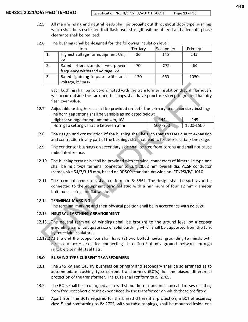
12.6 The bushings shall be designed for the following insulation level:
Item Tertiary Secondary Primary
1. Highest voltage for equipment Um, kV
36 145 245
2. Rated short duration wet power frequency withstand voltage, kV
70 275 460
3. Rated lightning impulse withstand voltage, kV peak
170 650 1050
Each bushing shall be so co-ordinated with the transformer insulation that all flashovers will occur outside the tank and bushings shall have puncture strength greater than dry flash over value.
12.7 Adjustable arcing horns shall be provided on both the primary and secondary bushings. The horn gap setting shall be variable as indicated below:
Highest voltage for equipment Um, kV 145 245
Horn gap setting variable between ,mm 500 -900 1200-1500
12.8 The design and construction of the bushing shall be such that stresses due to expansion and contraction in any part of the bushings shall not lead to its deterioration/ breakage.
12.9 The condenser bushings on secondary side shall be free from corona and shall not cause radio interference.
12.10 The bushing terminals shall be provided with terminal connectors of bimetallic type and shall be rigid type terminal connector to suit 28.62 mm overall dia, ACSR conductor (zebra), size 54/7/3.18 mm, based on RDSO’s standard drawing no. ETI/PSI/P/11010
12.11 The terminal connectors shall conform to IS: 5561. The design shall be such as to be connected to the equipment terminal stud with a minimum of four 12 mm diameter bolt, nuts, spring and flat washers.
12.12 TERMINAL MARKING The terminal marking and their physical position shall be in accordance with IS: 2026
12.13 NEUTRAL EARTHING ARRANGEMENT
12.13.1 The neutral terminal of windings shall be brought to the ground level by a copper grounding bar of adequate size of solid earthing which shall be supported from the tank by porcelain insulators.
12.13.2 At the end the copper bar shall have (2) two bolted neutral grounding terminals with necessary accessories for connecting it to Sub-Station’s ground network through suitable size mild steel flats.
13.0 BUSHING TYPE CURRENT TRANSFORMERS
13.1 The 245 kV and 145 kV bushings on primary and secondary shall be so arranged as to accommodate bushing type current transformers (BCTs) for the biased differential protection of the transformer. The BCTs shall conform to IS: 2705.
13.2 The BCTs shall be so designed as to withstand thermal and mechanical stresses resulting from frequent short circuits experienced by the transformer on which these are fitted.
13.3 Apart from the BCTs required for the biased differential protection, a BCT of accuracy class 5 and conforming to IS: 2705, with suitable tappings, shall be mounted inside one
604381/2021/O/o PED/TI/RDSO440

Specification No. TI/SPC/PSI/AUTOTR/0091 Page 14 of 50
of the bushings of the secondary side of the transformer for use with the winding temperature indicator (WTI).
13.4 The BCTs and the bushings shall be so mounted that removal of a bushing without disturbing the current transformers, terminals and connections or pipe work is easy and convenient.
13.5 The leads from the BCTs shall be terminated in terminal boxes provided on the bushing turrets. Suitable links shall be provided in the terminal boxes for shorting the secondary terminals of the BCTs, when not connected to the external measuring circuits.
13.6 The leads from the secondary winding of the BCTs terminated in the terminal box on the bushing turret upto the marshalling box shall be of 1100 V grade, PVC insulated, PVC sheathed, armoured, stranded copper cable of cross-section not less than 4 mm2 to IS: 1554 (Part-I).
13.7 Cable glands of proper size shall be provided in the terminal boxes to lead in/lead out the cables.
14.0 CLEARANCES
The relative orientation in space of the bushings fitted with terminal connectors, the main tank, radiators, conservator, pressure relief device, oil piping and other parts when mounted on the transformer shall be such that the various clearances in air from bushing live parts shall not be less than the appropriate values given hereunder:
1.Highest voltage for equipment Um, kV 245 145
2.Minimum clearance, mm 1900 1300
The same distance shall apply for clearance phase - to - earth including oil piping work, conservator, pressure relief device and such other parts), phase to phase, and towards terminals of a lower voltage winding.
15.0 MOTORISED ON LOAD TAP CHANGER
15.1 Each transformer shall be provided with on load tap changing mechanism. This shall be designed suitable for remote control operation from switch boards in the control room, in addition to being capable of local manual as well as local electrical operation and the control scheme of tap changers of each single phase transformer phase shall be designed to ensure simultaneous operation of other two units of the 3 phase bank.
15.2 Voltage Class for tap changer for graded insulated solidly earthed transformer winding
shall correspond to the highest voltage class of the winding at points where taps are provided. The switch shall be of rotary type and have a snap action.
15.3 The tap shall be provided on the series end of the 132 KV winding of the auto transformer.
15.4 The on load tap changer shall include the following:-
An oil immersed tap selector and arcing switch or arc suppressing tap selector provided with reactor or resistor for reduction of make and break arcing voltages and short circuits.
Motor driven drive mechanism.
Control and protection devices.
Manual control of the tap change gear.
Local/remote control of tap change gear.
Local/ remote tap changer position indicator.
604381/2021/O/o PED/TI/RDSO441

Specification No. TI/SPC/PSI/AUTOTR/0091 Page 15 of 50
15.5 The on load tap changer shall be designed so that the contacts do not interrupt arc
within the main tank of the transformer. The tap selector and arcing switch of the arc suppressing tap selector switch shall be located in one or more oil filled compartments mounted on the transformer tank. The compartment shall be so designed that the oil in the tap selector compartment shall not mix with oil in the transformer tank. Oil preservation system for OLTC shall be separated from main tank oil preservation system.
15.6 The compartment housing the tap selector and arcing switch shall be provided with a means of releasing the gas produced by arcing and with a Buchholz relay to indicate accumulation of gas in the compartment and shall be provided with alarm/trip contact of appropriate voltage and current rating.
15.7 The tap changer shall be capable of permitting parallel operation with other transformers of the same type and it shall be suitable for bi-directional flow of rated power.
15.8 The tap changer shall be capable of changing taps continuously on full load without any delay other than the minimum inherent delay in the mechanism between completions of one tap change and commence of the next.
15.9 The manual operating device for tap changing shall be so located on the transformer that it can be operated by a man standing at the level of the transformer. It shall be strong and robust in construction.
15.10 The motor operated drive mechanism shall be of stored energy type and shall ensure positive completion of load current transfer once initiated without any possibility of stopping in an intermediate position even in case of failure of external power supply to the drive mechanism.
15.11 The drive mechanism shall include a brake or clutch to allow only one step of tap change for each tap change initiating impulse.
15.12 Limit switches and mechanism stops shall be provided on the driver mechanism to prevent over travel beyond the max raise and lower positions. The drive mechanism shall be locked out when tap changer control switch are in operated position.
15.13 A hand crank or wheel shall be provided. The hand crank shall be electrically interlocked to prevent operation of the mechanism by motor while the cranked wheel is engaged.
15.14 Under abnormal conditions such as may occur if the controlling one tap changer sticks, the arrangement must be such that out of step conditions is limited to one tap difference between the units. Details of out of step protection provided for the taps should be furnished in the tender.
15.15 The local control cabinet of the on load tap changer shall consist of :
A device suitable for providing a time delay in the range from 13 to 60 sec in both raise and lower direction. The time delay shall apply only to the first step of a tap change.
Raise or lower spring return to off type control switch or raise and lower push button switch.
Tap position indicator with tap mark and corresponding rated voltage marked on the instrument. The tap position indicator shall include an initiating device for operating the remote tap position indicator.
Electrically interlocked reversing contactor. The reversing contactor shall preferably be interlocked mechanically also.
604381/2021/O/o PED/TI/RDSO442

Specification No. TI/SPC/PSI/AUTOTR/0091 Page 16 of 50
15.16 For the purpose of a parallel operation of the transformers the following additional device shall be provided with each transformer.
CT for relaying necessary for operating circulating current paralleling circuit i.e. paralleling is done by circulating current method
OR
Line drop compensation with adjustable reactance suitable for reversing if paralleling by reverse reactance method is adopted.
Master follower maintained contact selector switch for each transformer bank. The details of master follower scheme shall be furnished by manufacturer.
There shall be provision of necessary interlock for blocking independent control when the banks are in parallel.
15.17 The supplier shall furnish in addition to the equipment above, the following accessories mounted on a separate panel to be installed in the purchasers control room for remote operation.
Raise and lower push bottom switch.
Remote tap position indicator with sensing motor with at least F class insulation and other required devices. The tap position indicator shall bear the tap number and corresponding rated voltage engraved on it.
Tap change in progress indication lamps.
Tap changer of parallel operating transformers are not in same tap indication (out of step indication with alarm and visual indication).
Failure of AC supply to tap changer panel.
The changer shall in general conform to IS: 8464 and IEC: 60214.
The control schemes and equipment ensuring better performance than those guided by the description furnished in above mentioned clauses may also be accepted.
Complete particulars of the tap changer and its procedure of functioning shall be furnished in details along with tender.
Major components of the tap changer shall have name plates stating its capacity and rating etc.
16.0 COOLING EQUIPMENT
16.1 Transformer cooling shall be effected by use of two 50 percent bank or directly mounted radiators on the tank. The connections between the two shall be made with flanges provided with gaskets and indicating shut off valves provided at both connections ends, which can be fastened either in open or close position.
16.2 There shall be one stand by fan in each 50 percent bank in addition to the actual requirements for fans in each bank for ONAF rating. For OFAF rating the cooling system shall in addition contain electric motor driven oil pump having 100% stand by capacity. Stand by fan and electric motor driver oil pump shall come into operation automatically in the event of failure of any fan or oil pump in the bank.
16.3 The oil circuit of all cooler banks shall be provided with oil flow indicators, shut off valves lifting lugs top and bottom oil filtering valves, air release plugs, drain valve and thermometer pockets fitted with captive screw cap on the inlet/outlet branches of each separately mounted cooler bank
16.4 Cooling fans for each unit shall be housed in fan box to prevent ingress of rain water. Each fan shall be suitably protected by galvanized wire mesh guard.
604381/2021/O/o PED/TI/RDSO443
Specification No. TI/SPC/PSI/AUTOTR/0091 Page 17 of 50
16.5 Centrifugal oil pump shall be used. Measures shall be taken to prevent mal-operation of Buchholz relay when all oil pumps are simultaneously put into service. The pump shall be so designed that pump impeller will not restrict the natural circulation of oil, when the pump is not in use/ operation.
16.6 Cooling fan and oil pump motors with ‘F’ class insulation shall be suitable for operation on 230 volt, single phase, 50 cycle power supply with variation in supply voltage and frequency.
16.7 An oil flow indicator with alarm contacts shall be provided in each oil pump circuit to indicate flow of oil in the normal direction and to actuate an alarm if the flow of oil is stopped or is in reverse direction.
16.8 The coolers and its accessories shall preferably be hot dip galvanized or corrosion resistant paint should be applied to it.
16.9 Design of cooling system shall satisfy the requirement as stipulated under clause “performance”.
17.0 CONTROL OF COOLER OPERATION
17.1 The transformer shall be of ONAN/ONAF/OFAF cooling (50 MVA with ONAN & 75 MVA with ONAF and 150 MVA with OFAF) where the cooler fans shall come into service through contact of winding temperature indicator at predetermined temperature of transformer winding. The temperature setting for operation of fan and oil pump shall be adjustable over a reasonable range. Hunting of the transformer cooling equipment shall be avoided by providing suitable range settings. Separate winding temperature indicator with necessary contacts shall be provided and housed in local control kiosk for control of pumps and fans.
17.2 Suitable manual control facility for cooler fans and oil pumps shall be furnished.
17.3 For control of cooler fans and oil pumps separate weather and vermin proof control cubicle shall be furnished and installed near the transformer.
17.4 Provision to be made for two separate incoming for AC source of power supply to the control cubicle. In case of power supply failure of one incomer, automatic change over to the feeder shall take place. Each cooling fan and oil pump motor shall be provided with starter, thermal over load relays with built in single phasing preventer and short circuit protection. The starting circuits shall include time delay relay to save the motors from the effects of switching surges. The temperature of the transformer winding at which the fan and oil pump will come into service shall be indicated along with the range of adjustments available in the system.
18.0 FAULT INDICATING DEVICE
18.1 For each cooling fan alarm contact shall be furnished to indicate the faulty fan, when the oil flow stops with pump on and alarm contact preferably fitted with oil flow indicator should initiate an alarm.
18.2 An alarm for cooler supply auto changer shall be provided. All these alarms shall be available in remote control room. The manufacturer shall also indicate if additional alarm/indication lamp is required to be provided in purchasers control room. The panel shall be supplied by the contractor.
18.3 FAN GROUP OPERATION INDICATING DEVICE
604381/2021/O/o PED/TI/RDSO444

Specification No. TI/SPC/PSI/AUTOTR/0091 Page 18 of 50
Indications shall be available in purchasers control room to identify which of the
groups are in operation.
Each motor pump should be enclosed in an oil tight container with motor leads brought through hermetically sealed bushings. The moving parts of the motor and pump shall be readily removable without dismantling the cooler and with minimum spillages of oil.
The heat exchanger (radiators) shall be fabricated from corrosion resistant pressed steel of adequate thickness and shall be so arranged that these shall be accessible for cleaning and painting in future and shall ensure that gas pocket are not formed when the tank is being filled.
The cooler units shall be connected to tank by machined steel flanges welded to cooler unit and to the tank and provided with gaskets. At each cooler unit connections there shall be provided an indicating shut up wall on the tanks which can be fastened in either open or closed position. A separate oil tight blank flange shall be provided for each tank connection for use when the cooler unit is detached.
19.0 PARTS, FITTINGS AND ACCESSORIES
19.1 Apart from the parts, fittings and accessories specifically detailed in the foregoing clauses, the parts, fittings and accessories detailed hereunder shall be supplied with each transformer.
19.2 Conservator tank: It shall be of adequate capacity and complete with supporting bracket or structure, oil filling cap and drain valve of size 25 mm. The cylindrical portion of the conservator tank shall be of single piece construction without any gasket joint. Suitable air cell / separator arrangement of high quality material shall be provided in the conservator to ensure that the transformer insulating oil does not come in contact with air. The material of cell / separator shall be coated fabric consisting of highly resistant polyamide fabric, externally coated with perfectly transformer oil resisting coating (chemical), inner coating resisting ozone and weathering. Suitable instructions may please be provided for installation / commissioning and future maintenance of the air cell / separator arrangement. A portion of the oil pipeline connecting the tank with the conservator shall be arranged at a rising angle of 30 degree to 90 degree with the horizontal and shall consist of 75mm dia inside diameter pipe so as to facilitate the housing of oil and gas operated relays. Conservator shall have two filter valves, one at the bottom at one end, the other at the top at the opposite end, one shut off valve, one sump with small drain valve and one sampling cock in addition to the valves specified in the accessories of the main tank.
19.3 Oil level gauge: It shall be of magnetic type having a dial diameter of 250mm.The gauge shall have markings corresponding to minimum oil level, maximum oil level and oil level corresponding to oil temperature of 300C, 450C and 850C. The oil level indicator shall be so designed and mounted that the oil level is clearly visible to an operator standing on the ground.
19.4 Silica gel breather: It shall be complete with Orange Silica Gel (round balls 2 to 5mm) with quantity of two DTO-8 silica gel connecting with flanged mounting two pipes control through two different valves as per DIN:42567 & IS:3401. The connecting pipes shall be secured properly. The container of the silica gel breather shall be of transparent material suitable for outdoor application. The connecting arrangement of the silica gel breather shall be flange type.
19.5 Pressure relief device: It shall operate to release internal pressure at pre-set value without endangering the equipment or operator and shall be of instantaneous reset type. Shroud Pressure relief device will be used and have provision of discharge of oil
604381/2021/O/o PED/TI/RDSO445
Specification No. TI/SPC/PSI/AUTOTR/0091 Page 19 of 50
from PRD to safe place by closed pipeline. This avoids hazards of fire and it is safe to persons working near Transformer & it is environmental friendly.
19.6 Filter valves: The bottom and upper filter valves shall be of 50 mm size and suitably baffled to reduce aeration of oil. The valves shall be flanged to seat 40 mm adopter threaded to thread size P 1-½ for connection of oil filtration plant.
19.7 Drain valve: It shall be of size 80 mm fitted with an oil sampling device of size 15 mm.
19.8 Equipment Earthing terminals: Two earthing terminals shall be provided on the tank for its earthing with the help of 3 mild steel flats, each of size 75 mm x 8 mm. The terminals shall be clearly marked for earthing.
19.9 Buchholz relay: It shall be of double float type, with two shut - off valves of 80 mm size, one between the conservator tank and the Buchholz relay and the other between the transformer tank and the Buchholz relay. The relay shall have one alarm contact and one trip contact with none of the contacts being earthed. The contacts shall be of magnetic switch or micro switch type, electrically independent and wired up to the marshalling box. A testing petcock shall be brought down through a pipe for the purpose of sampling the gas, if any, collected in the Buchholz relay.
19.10 Oil temperature indicator (OTI) : It shall have one alarm contact, one trip contact and two normally open spare contacts none of the contacts being earthed. The contacts shall be electrically independent. The OTI shall have a local /remote indication (in control panel) for oil temperature.
19.11 Winding temperature indicator (WTI): It shall have one alarm contact, one trip contact; contacts for fan & pump operations and two normally open spare contacts with none of the contacts being earthed. The contacts shall be electrically independent. The WTI shall have a local /remote indication (in control panel) for oil temperature.
19.12 Thermometer pockets: A separate thermometer pocket with cap shall be provided on the bell tank for measuring the top oil temperature in the tank.
19.13 Rating plate: The rating plate shall indicate the ratings of the transformer, the connection diagram of the windings, the particulars of the bushing current transformers and other details as per IS: 2026. The rating plate shall be both in English and Hindi version.
19.14 Nitrogen injection fire prevention and extinguishing system: The complete arrangement of Nitrogen injection fire prevention and extinguishing system has to be provided with the transformer. The specification and other requirements of this system have to be as per details given in the Annexure-1 of the latest specification of Single Phase Traction Power Transformer i.e. TI/SPC/PSI/TRNPWR/3201 or latest.
19.15 Thermo Siphon Filter System This is to be provided for absorbing the moisture present in the insulating oil with the natural convection. The full details for installation and subsequent maintenance have to be furnished to RDSO and the consignee.
19.16 Fiber Optic Winding Hot Spot Temperature Monitor: Fiber optical winding hot spot temperature monitor to be provided with the transformer windings, connected in addition to the winding temperature indicator in parallel to measure transformer winding hot spots in real time and activate control of the cooling system. The specification and other requirements of this system have to be as per details given in the Annexure-4.
19.17 All valves shall be of the double flange type and fitted with suitable blanking plates on the outer face of the exposed flange.
604381/2021/O/o PED/TI/RDSO446

Specification No. TI/SPC/PSI/AUTOTR/0091 Page 20 of 50
19.18 The capillary tubes for temperature indicators shall be able to withstand normal bending. They shall be supported properly without sharp or repeated bends or twists.
19.19 The manufacturers of Part, Fittings, & Accessories for the Transformer shall be mentioned in the SOGP, BOM/QAP & got approved. During prototype test, the accessories will be tested & performance monitored either by Functional testing or by Test Certificate (TC) verification as categorised below:
SN Name of the accessory Category
1. On Load Tap changer Functional testing
2. Fire Extinguishing System Functional testing
3. Bucholz relay TC Verification
4. Pressure Relief Device TC Verification
5. Magnetic Oil level Gauge TC Verification
6. Bushing Current Transformer TC Verification
7. Silica gel Breather TC Verification
8. Wheel Valve, Double Flanged valve TC Verification
9. Analogue Type Temperature Indicators (WTI/OTI with four electrical contacts)
TC Verification
10. Terminal Connectors TC Verification
11. Radiators TC Verification
12. Fire Optic Winding Hot Spot Temperature Monitor TC Verification
Henceforth, while ordering Traction Power Transformer Autotransformer, a copy RDSO approved SOGP should be called for by the users. This document shall form basis for ordering accessories in the future. In case manufacturers desire to change a particular make of accessory, prior approval of RDSO would be required and SOGP as well as Bill of Material (BOM)/Quality Assurance Plan shall have to be got approved from RDSO. In case of change of make of accessory under Functional testing for regular production, the RDSO’s approval would be required separately on SOGP and BOM/QAP. The Traction Power Transformer manufacturer shall be responsible for availability of compatible accessories for the equipment approved.
20.0 FASTENERS All fasteners of 12 mm diameter and less exposed to atmosphere shall be of stainless
steel and those above 12 mm diameter shall preferably be of stainless steel or mild steel hot dip galvanized to 610 g/m2 of zinc. The material of the stainless steel fasteners shall conform to IS: 1570 (Part- V). Grade 04Cr17Ni12Mo2.
21.0 PAINTING
21.1 Shot blasting / sand blasting shall be done on the transformer tank to remove all scales, rust and other residue before applying the paint inside the tank. All steel surfaces which are in contact with insulating oil shall be painted with heat resistant oil - insoluble insulating varnish.
21.2 All steel surfaces exposed to weather shall be properly descaled/grit blasted. The epoxy and polyurethane protective paints as per ISO/EN 12944 have to be provided for proper protection against corrosive and coastal environments and give life of approx. 12-15 years. All the external surfaces of the Transformer shall be given first coat of epoxy zinc rich (having minimum 83% metallic zinc) primer (50 micron thickness), intermediate coat of epoxy chemical and corrosion resistant High Build Epoxy Intermediate paint (100 micron thickness) and final coat of Glossy Aliphatic Acrylic Polyurethane Coating paint (50 micron thickness). The total dry film thickness of the paints shall be minimum 200 micron. The
604381/2021/O/o PED/TI/RDSO447

Specification No. TI/SPC/PSI/AUTOTR/0091 Page 21 of 50
shade of paint shall be gray as shade 631 of IS: 5. Same paints have to be applied at damaged surfaces, if any, at site during erection /commissioning of the transformer. One final coat of polyurethane paint has to be applied to ensure proper smoothness and finish.
21.3 For panels like marshalling Box, OLTC drive mechanism box and RTCC panels Powder Coating
painting of minimum 80 micron thickness is to be done. The shade of paint shall be shade 631 of IS: 5 for the marshalling Box, OLTC drive mechanism box and shade 216 of IS: 5 for the RTCC Panel.
22.0 TESTING OF TRANSFORMER
22.1 General
22.1.1 Once the design and drawings as well as QAP have been approved and a written advice has been given, the manufacturer shall take up manufacture of the prototype of the transformer. It is also clearly understood that any change or modification required to be done in the prototype shall be done expeditiously, notwithstanding approval having already been given for the designs and drawings. Such change or modification shall be incorporated in the drawings.
22.1.2 Prior to giving a call to the purchaser / DG(TI) , RDSO, Lucknow , for inspection and testing of the prototype, the manufacturer shall submit a detailed test schedule for each of the tests and the number of days required to complete all the tests at one stretch. Once the schedule is approved, the tests shall invariably be done accordingly. However, during the process of type testing or even later, the purchaser reserves the right to conduct any additional test(s), besides those specified herein, on any equipment / item so as to test the equipment/item to his satisfaction or for gaining additional information and knowledge. In case any dispute or disagreement arises between the manufacturer and representative of the purchaser/ DG(TI),RDSO, Lucknow, during the process of testing as regards the procedure for type tests and /or the interpretation and acceptability of the results of type tests , it shall be brought to the notice of the purchaser /DG(TI),RDSO, Lucknow, as the case may be, whose decision shall be final and binding. Only after the prototype transformer is completed and ready in each and every respect, shall the manufacture give the actual call for the inspection and testing with at least 15 days’ notice for the purpose.
22.1.3 The type tests shall be carried out in accordance with RDSO ISO procedures, Quality Plan For Traction Power Transformer Prototype testing & with the relevant standards as modified or amplified by the specification where ever applicable, at the works of the manufacturer, or at a reputed testing laboratory in the presence of the authorized representative of the DG/TI/RDSO, Lucknow. However for the tests in the third party laboratory the presence of representative of the purchaser/DG (TI)/RDSO, Lucknow may be decided by the RDSO. Manufacturer shall furnish the type and routine test schedule based on the RDSO specification for approval before commencement of tests.
22.2 Tests during manufacture
22.2.1 Though the tests described below shall form a part of the type tests, the manufacturer shall carry out these tests on each and every unit during the process of manufacture and submit the test reports to the Purchaser's Inspector deputed for witnessing the routine tests. However, the vacuum test and pressure test shall be conducted only on the prototype unit.
1. Oil leakage test. 2. Vacuum test.
604381/2021/O/o PED/TI/RDSO448

Specification No. TI/SPC/PSI/AUTOTR/0091 Page 22 of 50
3. Pressure test. 4. Insulation test for core bolts. 5. Test for pressure relief device.
22.2.1.1 Oil leakage test: The transformer with its radiators, conservator tank and other parts, fittings and accessories completely assembled shall be tested for oil leakage by being filled with oil conforming to IS: 335 (Type-II) at the ambient temperature and subjected to a pressure corresponding to twice the normal static oil head or to the normal static oil head plus 35 kN/m2 (0.35 kgf/cm2), whichever is lower, the static oil head being measured at the base of the tank. This pressure shall be maintained for a period of not less than 12 h, during which time no leakage shall occur.
22.2.1.2 Vacuum test: The transformer tank only shall be tested at a vacuum of 3.33kN/m2 (0.0333kgf/cm2) for 60 min. The permanent deflection of flat plates after release of vacuum shall not exceed the values specified below:
Horizontal length of flat plate Permanent deflection, mm
Upto and including 750 mm 5.0
751 mm to 1250 mm 6.5
1251mm to 1750 mm 8.0
1751 mm to 2000 mm 9.5
2001 mm to 2250 mm 11.0
2251 mm to 2500 mm 12.5
2501 mm to 3000 mm 16.0
above 3000 mm 19.0
22.2.1.3 Pressure test: Every transformer tank, radiator and conservator tank shall be subjected
to an air pressure corresponding to twice the normal static head of oil or to the normal static oil head pressure plus 35 kN/m2 (0.35 kgf/cm2), whichever is lower, as measured at the base of the tank. The pressure shall remain constant for 1 h to indicate that there is no leakage.
22.2.1.4 Insulation test for core bolts: This test shall be done as described in Clause 8.4 of this specification.
22.2.1.5 Test for pressure relief device: Every pressure relief device shall be subjected to gradually increasing oil pressure. It shall operate before the pressure reaches the test pressure specified in Clause 22.2.4 hereof and the value at which it has operated shall be recorded.
22.2.2 During the prototype testing, at following manufacturing stages the tests may be witnessed by the representative of the purchaser /DG (TI), RDSO, Lucknow at the works of the manufacturer.
22.2.2.1 Motorised On Load tap changer 22.2.2.1 Fire Extinguishing System 22.2.2.1 Transformer Tank 22.2.2.1 Transformer CORE. 22.2.2.1 Transformer winding Assembly
22.2.2.1 Motorised ON Load tap changer: Following tests shall be conducted
(i) Visual and dimensions check: Visual and dimensions check of the complete Motor Drive unit (MDU) of the On Load tap Changer shall be carried out as per the approved drawings and requirements mentioned in the clause no. 15.0 of this specification.
604381/2021/O/o PED/TI/RDSO449
Specification No. TI/SPC/PSI/AUTOTR/0091 Page 23 of 50
(ii) Mechanical Endurance test of diverter switch compartment: The driver endurance test
is to be conducted for 4000 operations in oil filled tank. No abnormal sound should be observed, after the endurance test the diverter switch visual examination of diver switch should be conducted.
(iii) Operation check of the tap changer with drive mechanism: With the on-load tap-changer fully assembled but without the contacts energized, ten complete cycles of operation shall be performed without failure at the supply voltage of 93.5V DC, 121V DC and 110V DC.
(iv) Sequence test: During the operation check (iii, above) a sequence of operations of the on-load tap changer shall be recorded, the operation of the diverter or selector switch being recorded oscillographically.
(v) Contact resistance Measurement: Contact resistance at every tap position shall be measured before and after endurance test. Contact resistance shall be less than 2 milli ohm.
(vi) Pressure test and Vacuum test: All liquid containing compartments shall be tested at a pressure and vacuum declared by the manufacture.
(vii) HV Test on auxiliary Circuit. All auxiliary circuits shall be subjected to a separate source AC withstand test of 2kV for 1 minute between all live terminals and the frame/earth. - Equipment should withstand the test.
(viii) Manual Operation: Five complete cycle of raise and lower operation shall be verified with manual handle.
(ix) Type tests reports of the tap changer of the type tests as per IEC: 60214/IS: 8468 shall be submitted (Clause no. 22.4 of this specification).
22.2.2.2 Fire Extinguishing System: The tests shall be conducted as mentioned in the NIFPES specification at Annexure- 1 of the latest specification of Single Phase Traction Power Transformer i.e. TI/SPC/PSI/TRNPWR/3201 or latest.
22.2.2.3 Transformer Tank: following tests shall be conducted: (i) The pressure test and vacuum test shall be done as per the clause no. 22.2.1.3 &
22.2.1.2 of this specification. (ii) The Dye Penetration (DP) Test at the jacking and lifting pads.
22.2.2.4 Transformer CORE. (i) 2 kV r. m. s. withstand voltage between Core clamping bolts and core laminations
for duration of 60 seconds. (ii) Stack height, Diameter and window dimensions as per the approved drawings. (iii) The manufacturer test certificate of the CORE material shall be submitted.
22.2.2.5 Transformer Winding Assembly: Following measurements/inspection shall be conducted on HV, LV & Regulating windings.
(i) Thickness of the bare and insulated conductor. (ii) Width and Thickness of the conductor. The ratio of width to thickness of copper
conductor used for winding shall not exceed 5:1. (iii) Number and location of Probes for Fiber Optic Temperature Measurement. The
Transformer manufacturer should submit the details that the probes are located in the hottest point of the winding.
22.2.3 The requirement of the functional testing by RDSO for OLTC and NIFPES may be waived off subject to the following:
604381/2021/O/o PED/TI/RDSO450
Specification No. TI/SPC/PSI/AUTOTR/0091 Page 24 of 50
(i) Earlier RDSO has witnessed the item at the works of manufacturer and
manufacturer submits a declaration that the design of manufactured unit is identical to that, which has been witnessed by RDSO.
(ii) The transformer manufacturer has witnessed the unit as per the tests/formats mentioned in the specification.
22.2.4 The purchaser or their representative may, if he so desires, carry out any checks or tests on the quality of manufacture at any stage during coil winding, drying of coils, assembly of coils on core and method of drying, vacuum impregnation, tightness of core clamping bolts, adequacy of pressure on coils or any other aspects as deemed so as to ensure that proper quality is maintained.
22.3 Type tests
The type tests shall be carried out on the prototype transformer at the works of the manufacturer or at any reputed laboratory in the presence of the representative of the purchaser /DG (TI), RDSO, Lucknow, and in accordance with the relevant specifications and as altered, amended or supplemented by this specification. The following shall constitute the type tests:
1. Temperature - rise test. 2. Lightning impulse test. 3. Test with lightning impulse, chopped on the tail. 4. Short Circuit Test 5. Measurement of acoustic sound level. 6. Measurement of partial discharge quantity. 7. Measurement of harmonics of no - load current.
22.3.1 Temperature - rise test
The temperature - rise test shall be done with the tap changer on the lowest tap position with IS: 2026 (Part II)
The tests shall be done continuously without any power supply interruption. In case interruptions of power supply do take place for some reason, then the entire test shall be repeated after steady state conditions are attained.
22.3.1.1 The points to be ensured during the temperature - rise test shall be:
i. The ambient temperature shall be measured using alcohol in glass thermometers only. ii. The winding temperature shall be determined by the resistance method only.
iii. The temperature of the top oil shall be measured by an alcohol in glass thermometer placed in an oil- filled thermometer pocket.
iv. The average oil temperature shall be calculated as the difference between the top oil temperature and half the temperature drop in the cooling equipment (radiators).
v. The temperature of the hot spot in the winding shall be the sum of the temperature of the top oil The calculated hot spot temperature of the winding shall be the sum of top oil temperature (calculated after considering ambient temperature of 50oC) and 1.1 times the temperature rise of the winding above the average oil temperature.
vi. The Dissolved Gas Analysis shall be conducted on the sample of oil drawn from the transformer tank before & after temperature rise test.
22.3.1.2 Determination of thermal time constant of the windings: The thermal time constant of the primary and secondary windings under both rated and overloads shall be verified during the temperature - rise tests.
604381/2021/O/o PED/TI/RDSO451

Specification No. TI/SPC/PSI/AUTOTR/0091 Page 25 of 50
22.3.2.2 The temperature rise of the oil, windings and current carrying parts in air shall not
exceed the values stipulated in this specification. The winding hotspot temperature shall not exceed 1150 C.
22.3.2.3 Testing and calibration of the temperature indicators: The functioning of the OTI, WTI and FOS shall be verified during the tests described above. Both the OTI and WTI shall be recalibrated, if necessary, to reflect the respective temperatures correctly. In particular, the reading of the WTI shall be same as the calculated value of the hot - spot temperature of the winding.
22.3.2.4 Determination of the thermal time constant of the WTI: The thermal time constant of the WTI shall be determined for comparison with the thermal time constant of the winding of the transformer with respect to the transformer oil. For this purpose, the indications of the WTI and the OTI shall be recorded every 1 or 2 min during the first 1 h from the instant the transformer is loaded. From the slope of the curve plotted with the time on the X - axis and the difference between the readings of the WTI and OTI at the particular time on the Y - axis, the thermal time constant of the WTI shall be determined. This value shall not vary appreciably from the thermal time constant of the winding as calculated theoretically and as ascertained from the slope of the cooling curves.
22.3.2 Lightning impulse test
This test shall be done in accordance with IS: 2026 (Part III). Each of the terminals of the primary and secondary windings shall be tested with the following voltages:
1. Highest voltage for equipment, Um, kV 245 145
2. Lightning impulse withstand voltage, kV peak 950 650
22.3.3 Test with lightning impulse, chopped on the tail
This test shall be done in accordance with IS: 2026 (Part III) with the appropriate test voltage.
22.3.4 Short - circuit test
22.3.4.1 The short- circuit test shall be conducted in accordance with IS: 2026 (Part I) with the following schedule:
22.3.4.2 Prior to commencement of the test, the following measurements/ tests shall be made:
1. Insulation resistance of the windings with respect to the earth and between the windings.
2. No- load current. 3. No- load loss. 4. Resistance of the windings. 5. Percentage impedance voltages. 6. Load loss. 7. Voltage ratio. 8. Di- electric tests comprising:
i. Separate - source voltage withstand test, and ii. Induced overvoltage withstand test.
9. Recording of recurrent surge oscillogram (RSO) at the highest, lowest and principal tapping.
22.3.4.3 The test shall preferably be done by closing the breaker on the secondary side after energizing the primary winding at its rated voltage.
604381/2021/O/o PED/TI/RDSO452

Specification No. TI/SPC/PSI/AUTOTR/0091 Page 26 of 50
22.3.4.4 The transformer shall be subjected to a total of seven shots in the following sequence:
1 st shot - Symmetrical current at the highest tap. 2 nd shot - Asymmetrical current at the highest tap. 3 rd shot - Asymmetrical current at the principal tap. 4 th shot - Symmetrical current at the principal tap. 5 th shot - Symmetrical current at the lowest tap. 6 th shot - Asymmetrical current at the lowest tap. 7 th shot - Symmetrical current at the lowest tap.
22.3.4.5 The duration of each shot shall be 0.5 0.25 seconds.
22.3.4.6 Percentage impedance voltage or inductance shall be measured after each shot.
22.3.4.7 Further testing and inspection of the transformer subjected to the short-circuit test shall be carried out as per IS: 2026(Part-I) with the modification that:
1. The dielectric routine tests shall be at 100% of the original test value. 2. The percentage impedance voltages measured after the short-circuit test shall not
vary by more than 2% from those measured before the short-circuit test.
22.3.4.8 On completion of the short-circuit test the transformer shall be untanked for inspection of the core and windings. In case the inspection of the core and windings do not reveal any apparent defects and the results of the short – circuit test, the values of percentage impedance voltages as also the results of the routine tests done after the short-circuit test are in order, the transformer shall be deemed to have passed the short-circuit test. If any of the results of the tests are not in order or the inspection of core and windings reveals any defect, then the transformer shall necessarily have to be dismantled completely for detailed inspection.
22.3.5.3 Frequency response analysis (FRA) of the prototype transformer is to be preferably carried out before and after the short circuit test to judge the healthiness of the transformer after short circuit and this can be kept as reference for future. Similar Frequency response analysis (FRA) records for other transformer units may preferably be furnished to be used for future reference.
22.3.6 Measurement of acoustic sound level
Measurement of acoustic sound level of the transformer, energised at rated voltage and frequency shall be carried out either as per Indian Electrical & Electronics Manufacturers Association (IEEMA) or as per National Electrical Manufacturers Association (NEMA) procedure.
22.3.7 Measurement of Partial discharge quantity
Partial discharge quantity of the windings shall be measured in accordance with IS: 6209 and IS: 2026 (Part – III).
22.3.8 Measurement of harmonics of no- load current
The magnitude of harmonics of no- load current, as expressed in percentage of the fundamental, shall be measured by means of a harmonics analyzer, in accordance with IS: 2026 ( Part- I ).
22.4 Motorized On Load tap – changer
22.4.1 Tests shall be carried out thereon in accordance with relevant IEC 60214 / IS: 8468
22.4.2 Test for temperature rise of contacts: the test shall be carried out at rated current of 800 A. The temperature rise shall not exceed the limit specified in IS: 8468.
604381/2021/O/o PED/TI/RDSO453

Specification No. TI/SPC/PSI/AUTOTR/0091 Page 27 of 50
22.4.3 Mechanical endurance test: With the tap-changer in oil, 100 operations shall be done
manually and 10,000 operations shall be done with the motor drive unit. An operation shall comprise moving the tap-changer from one tap position to the next higher or lower tap position. All the taps of the tap- changer i.e. highest position tap to the lowest position tap shall be covered during the test. While testing with the motor drive unit the DC voltage for the motor drive unit shall be adjusted to the values indicated below, and the number of operations at each value of voltage shall be as indicated against each.
1. At the minimum voltage of 93.5 V dc 2500 operations 2. At the maximum voltage of 121 V dc 2500 operations 3. At the rated voltage of 110 V dc 5,000 operations.
22.4.4 Milli-volt test: The test shall be done both before and after the mechanical endurance test to assess the condition of the contacts. The variation in the milli- volt drop values shall be not more than 20 %.
22.4.5 Short- circuit current test: The test shall be done in accordance with IS: 8468 with short –circuit currents of 10 kA, each of 5 s duration.
22.4.6 Dielectric tests: The tests shall be done in accordance with IS: 8468.
22.4.7 Auxiliary circuits insulation tests: Auxiliary circuits including the motor and other auxiliary equipment shall be tested in accordance with IS: 8468.
22.5 Condenser bushings
22.5.1 The type tests shall be carried out in accordance with IS: 5621 on porcelain housing of the condenser bushings. The following shall constitute the type tests:
(i) Visual inspection. (ii) Verification of dimensions. (iii) Electrical routine test. (iv) Porosity test. (v) Temperature cycle test. (vi) Bending test.
22.5.2 The type tests shall be carried out in accordance with IS: 2099 on the prototype of the condenser bushings. The following shall constitute the type tests:
(i) Wet power frequency withstand voltage test. (ii) Dry lightning impulse voltage withstand test. (iii) Thermal stability test. (iv) Temperature rise test. (v) Thermal short time current withstand test. (vi) Cantilever load withstand test.
(vii) Tightness test. (viii) Test of tap insulation. (ix) Tightness test at flange or other fixing device. (x) Measurement of partial discharge quantity.
22.6 Bushing type current transformers
The bushing type current transformers shall be tested in accordance with IS: 2705/16277 (Part-I & IV).
22.7 Buchholz relay
The Buchholz relay shall be tested in accordance with IS: 3637.
604381/2021/O/o PED/TI/RDSO454

Specification No. TI/SPC/PSI/AUTOTR/0091 Page 28 of 50
22.8 Terminal connectors
The terminal connectors shall be tested in accordance with IS: 5561.
22.9 Temperature indicators
The following tests shall be conducted on prototypes of OTI and WTI:
(i) Accuracy with reference to a standard instrument. (ii) Calibration of the indicators to reflect the actual temperature of the oil/winding. (iii) Dielectric test at 2.5 kV for 60 s. (iv) Vibration test. (v) Dust and water splash test to IP 55 degree of protection.
22.10 Pressure relief device
The following tests shall be conducted on the prototype of pressure relief device:
(i) Air pressure test. (ii) Leakage test. (iii) Contact rating and operation test. (iv) Dielectric test on contacts at 2.5 kV for 60 s.
22.11 Radiators
The radiators shall be tested for air leakage at a pressure of 2.5 kg/cm sq. The pressure shall remain constant for 1 h to indicate that there is no leakage.
22.12 Insulating Oil
The tests shall be carried out in conformity with IS: 335:2018 (Type-II) on the sample of new inhibited mineral insulating oil for use in the transformer. In addition to the requirement of IS: 335:2018 the insulating oil filled in the transformer shall also meet the following characteristics-
SN Parameter Requirements
1. Lowest Cold Start Energizing Temperature (LCSET) 0oC
2. Flash point Min, 140 oC
3. Presence of Oxidation Inhibiter
(DBPC-2, 6 ditertiary-butyl-para-cresol)
Range (0.25 to 0.30) %
4. Oxidation Stability:
(c) Total Acidity (Neutralisation value after oxidation)
(d) Total sludge after oxidation
Max, 0.2 mg KOH/g
Max, 0.05%
22.13 Routine tests
The following routine tests shall be performed on each transformer including the prototype unit in accordance with IS: 2026:
1. Visual examination 2. Insulation resistance test. 3. Measurement of no- load current. 4. Measurement of no- load loss. 5. Measurement of resistance of the windings. 6. Measurement of percentage impedance voltages. 7. Measurement of load loss. 8. Voltage ratio test.
604381/2021/O/o PED/TI/RDSO455

Specification No. TI/SPC/PSI/AUTOTR/0091 Page 29 of 50
9. Dielectric tests comprising:
a. Separate- source voltage withstand test, and b. Induced overvoltage withstand test.
10. Recording of recurrent surge oscillogram (RSO). 11. Tests on motorized On Load tap- changer. 12. Measurement of capacitance and tan-delta values 13. Frequency response analysis (FRA)
22.13.1 Visual examination: A general examination shall be made to check that the transformer conforms to the approved drawings. Various items are accessible for maintenance, the quality of workmanship and finish are of acceptable standards and all parts, fittings and accessories are provided.
22.13.2 Insulation resistance test: The insulation resistance of the windings with respect to the
earth and between the windings shall be measured using a 5 kV megger.
22.13.3 Measurement of no – load current: Measurement of no- load current referred to the primary side shall be done at 90%, 100% and 110% of the rated voltage at the principal tapping, low and high tap positions.
22.13.4 Measurement of no- load loss: Measurement of no- load loss referred to the primary side shall be done at 90 %, 100% and 110% of the rated voltage at the principal tapping, low and high tap positions.
22.13.5 Measurement of resistance of windings: The resistance of the windings shall be measured at all tapings and computed at 750 C.
22.13.6 Measurement of percentage impedance voltages: The percentage impedance voltages at principal, highest tap and lowest tap positions shall be measured at rated current and at ambient temperature and computed at 750 C.
22.13.7 Measurement of load loss: Load losses at rated current shall be measured at principal, highest tap and lowest tap positions at ambient temperature and computed at 750.
22.13.8 Voltage ratio test: Voltage ratio shall be measured at all tap positions.
22.13.9 Dielectric tests
Induced overvoltage withstand test: The test shall be done by applying the test voltage across the entire secondary winding as per IS: 2026(Part III).
Separate-source voltage withstand test: The test voltage to be applied shall be as under:
1. Highest voltage for equipment Um, kV 245 145
2. Rated short duration power frequency withstand voltage ,kV
395 275
22.13.10 Recording of recurrent surge oscillogram (RSO): The oscillograms shall be taken at the
low and high tap positions and principal tappings.
22.13.11 Tests on motorized on-load tap changer: The tests shall be conducted in accordance with IS: 8468/IEC:60214.
22.13.12 Measurement of capacitance and tan-delta values: The measurement of capacitance and tan-delta (dielectric loss factor) of the transformer windings shall be made by Schering Bridge.
604381/2021/O/o PED/TI/RDSO456

Specification No. TI/SPC/PSI/AUTOTR/0091 Page 30 of 50
22.14 During the routine tests on any unit if it is found that the no-load loss/ load loss at the
principal tapping exceeds the maximum guaranteed figures, then the transformer shall be rejected.
22.15 The prototype approval (if applicable) shall be accorded after conducting all the type and routine tests stipulated in this specification and as per RDSO ISO procedure. If the prototype of a transformer conforming to this specification has already been approved in connection with previous supplies to Indian Railways, fresh type testing may be waived at the discretion of the Purchaser, provided that no changes what so ever in the design or material(s) used or the process of manufacture have been made. However, the Purchaser reserves the right to conduct type tests if he deems it necessary to do so in the light of experience gained from previous supplies.
22.16 Only after approval of drawings incorporating changes, if any, as a result of the prototype tests and clear written approval of the results of the tests on the prototype is communicated by the Purchaser/DG (TI), RDSO, Lucknow, to the manufacturer, shall he take up bulk manufacture of the transformer - which shall be adopted for the prototype. In no circumstances shall materials other than those approved in the design/drawings and/or during the prototype testing be used for bulk manufacture on the plea that they had been obtained prior to the approval of the prototype.
22.17 The manufacturer may quote separately his charges for short-circuit tests. No charges shall be payable for any other type and routine tests.
23.0 TECHNICAL DATA AND DRAWINGS
23.1 The manufacturer shall furnish along with his offer, in the proforma at Annexure-I, the Schedule of Guaranteed Performance, Technical and Other Particulars (SOGP) for the transformer. The particulars shall be complete in all respects. The values/ information given in this SOGP, will be used for technical evaluation of the tender.
23.2 The manufacturer shall specifically indicate in a “Statement of Compliance" attached with the offer his compliance with each and every clause of this specification. In case the manufacturer wishes to deviate from any clause of this specification, he may do so giving reference to the clause(s) with the reasons/justification for the deviation. This shall be in the form of a separate statement called the "Statement of Deviations". If there is no deviation at all, a specific" NIL" “Statement of Deviations” shall be attached with the offer. If the "Statement of Compliance" and "Statement of Deviations" are not attached with the offer, it is not likely to be considered for the reason that it is an incomplete offer which cannot properly evaluated and compared with offers, if any.
23.3 The manufacturer shall furnish the following information along with his offer:
23.3.1 Calculations for:
(i) Temperature rise of winding at rated current. (ii) Thermal withstand capacity of the windings for a short circuit of 5 s duration. (iii) Mechanical forces in respect of the following as per IEEMA (Indian Electrical &
Electronic Manufacturer's Association) formulae given on Annexure-2. a. Asymmetrical short-circuit current. b. Hoop stress in primary and secondary windings. c. Compressive pressure in the radial spacers. d. Internal axial compressive force. e. Axial imbalance force. f. Radial bursting force. g. Resistance to collapse.
604381/2021/O/o PED/TI/RDSO457
Specification No. TI/SPC/PSI/AUTOTR/0091 Page 31 of 50
h. Bending stress on clamping ring and densified wood. i. Maximum allowable torque on pressure screws for coil clamping bolts at the
time of tightening, if any. (iv) Flux density with the characteristic curve. (v) Maximum value of inrush current.
23.3.2 Drawings for:
(i) Outline general arrangement drawing giving complete details of the transformer. (ii) Arrangement of the core, windings and magnetic path. (iii) Magnetizing characteristic of CRGO sheet steel. (iv) Drawing showing elevation of the core and winding and other insulation materials. (v) A sectional view showing the position of core cylinders, winding blocks, vertical ribs
and other insulating materials. (vi) Details of coil clamping arrangement. (vii) General arrangement of the off-circuit tap - changer.
(viii) Any other drawing as required by the purchaser.
23.3.3 Other documents for:
(i) Quality assurance plan for the transformer. (ii) ISO certification regarding quality system manufacturing, testing facilities, R&D
facilities and reliability. (iii) List of essential plant, machinery and testing facilities. (iv) Up-dated calibration certificate for the testing equipment. (v) Type test reports for the relevant rating of the tendered transformer. (vi) List of supplies & performance reports from the users for tendered transformer.
23.4 The manufacturer shall submit to DG(TI), RDSO, Lucknow for approval the following detailed dimensioned drawings as per Indian Railways standard in sizes of 210mm x 297mm or any integral multiples thereof:
(i) Outline general arrangement of the transformer indicating plan, front elevation, side elevation with all parts, fittings and accessories, electrical clearances as well as salient guaranteed particulars.
(ii) Internal arrangement of the transformer indicating primary and secondary bushing lead connections, core to core- clamp earthing, core- clamp to tank earthing, core- clamp to core-base bolting, and the locking arrangement of the core & coil assembly with the tank.
(iii) Cross sectional view of the core and windings with material specifications and makes.
(iv) Details of the pressure screws / oil dash-pot/ coil clamping bolts or other devices and their location with materials specifications and makes.
(v) Schematic view of the valves used on the transformer and the antitheft devices as to diagram.
(vi) Transport outline dimensional diagram. (vii) General arrangement of the on load tap-changer assembly with salient technical
parameters. (viii) Tap-changer cubicle layout. (ix) Schematic diagram for driving of motorized on load tap-changer from remote
control centre by telecommand and corresponding telesignalling. (x) Name and rating plate of motorized on load tap-changer. (xi) General arrangement of marshalling box indicating protection control equipment. (xii) Wring diagram of protection and control circuits marshalling box.
604381/2021/O/o PED/TI/RDSO458

Specification No. TI/SPC/PSI/AUTOTR/0091 Page 32 of 50
(xiii) Schematic diagram of protection and control circuits in marshalling box with cable
schedule. (xiv) Legend plate showing protection and control circuits for fitment in the marshalling
box. (xv) Oil communicating type bushing for primary side including cross-sectional view,
shed profile and salient electrical and mechanical characteristics. (xvi) OIP condenser bushing for secondary side including cross-sectional view shed profile
and salient electrical and mechanical characteristics. (xvii) Dimensional drawing, V-I characteristic and rating plate for bushing types current
transformers. (xviii) Rigid type terminal connector for primary side bushing terminal. (xix) Expansion type terminal connector for secondary side bushing terminal. (xx) Rating plate diagram of connections, both in English and Hindi versions. (xxi) Details of radiators including the painting schedule. (xxii) Details of breather
(xxiii) External cables run with cable schedule. (xxiv) Details of ‘O’ ring and different gaskets to be used in the transformer (xxv) Any other drawings considered necessary by the successful tenderer/ manufacturer
and/ or purchaser.
23.4.1 After approval, six copies of each of the approved drawings shall be supplied to each consignee(s). Besides, a copy of drawings on CD along with hard copy after final approval of the drawings shall be submitted to DG, RDSO, and Lucknow for records.
23.4.2 Two copies of the "Operation / Maintenance Manual" for each transformer shall be supplied to the consignee(s). One copy of the manual shall be supplied to the DG (TI), RDSO, Lucknow. While preparing the instruction and maintenance manual for inspection/test schedule for traction transformer issued by RDSO shall be taken into account.
24.0 CAPITALISATION OF TRANSFORMER LOSSES
The capitalized value of transformer losses shall be as low as possible and commensurate with optimum no-load and load losses. The capitalized value shall be computed as detailed at Annexure 3 and furnished along with offer. Capitalized value calculated, as per Annexure 3 shall be added to the unit cost of the transformer for taking into consideration the cost of losses during its service life.
25.0 SPARES
The manufacturer shall quote separately for the following essential spares for every lot of up to 5 transformers or part thereof:
(i) One set of primary coil, secondary coil and tapping coil. (ii) One primary bushing complete with parts, fittings and bushing type current
transformer. (iii) One secondary bushing complete with parts, fittings and bushing type current
transformer. (iv) One complete set of gaskets of all sizes required for use in the transformer. (v) One breather unit with silica gel. (vi) One set of radiator banks. (vii) One Buchholz relay.
(viii) One complete on load tap -changer. (ix) One each of terminal connectors for primary and secondary side bushing terminals. (x) One set of valves. (xi) One pressure relief device.
604381/2021/O/o PED/TI/RDSO459
Specification No. TI/SPC/PSI/AUTOTR/0091 Page 33 of 50
A separate quotation shall be furnished for any other spares that the manufacturer considers as necessary for maintenance of the transformer.
26.0 Warranty
Warranty of Traction Power Transformer (including accessories) shall be as per the IRS condition of contract.
27.0 ERECTION, TESTING AND COMMMISSIONING
27.1 The transformer shall be erected and commissioned by the Purchaser. Manufacturer shall invariably make available at site the services of an engineer of his to ensure, by his continued presence, that the process of erection, testing and commissioning of the transformer is in accordance with established practices. For this purpose prior intimation regarding the dates/period and locations at which the transformers are to be erected and testing / commissioning done shall be given by the Purchaser to the successful tenderer/manufacturer. No charges shall be payable by the purchaser to the successful tenderer/manufacturer for the services of his engineer in this regard.
27.2 If any transformer has been received at site in a damaged condition and in the opinion of the Railway's Engineer at site it is required to be repaired at the successful tenderer/manufacturer's works, the transformer shall be taken back to the works promptly and after repair, all necessary tests including the routine tests shall be done on the complete transformer in the presence of and to the satisfaction of the Railway's Engineer prior to returning the transformer to site. Such tests are necessary to ensure that the quality of the workmanship during repairs is satisfactory and shall be done free of cost. Any tests, as decided by the Railway's Engineer at site shall also be conducted on the transformer at site free of cost.
28.0 TRANSPORTATION OF THE TRANSFORMER
28.1 The transformer shall be transported depending upon the transport facilities available for the route i.e. by rail or truck or ship.
28.2 The transformer shall be dispatched with its core and windings along with the tap-changer assembly in the transformer tank filled with oil and the space above the oil filled with pure dry air or inert gas like nitrogen at a pressure slightly above atmospheric pressure. However, if there are limitations on account of weight, the tank shall be filled with nitrogen/dry air under pressure and the oil for the first filling shall be supplied separately in steel drums. In case the tank is filled with inert gas/dry air the temperature and pressure at the time of filling shall be marked conspicuously on the transformer.
28.3 All openings created on the tank by removal of any items shall be closed with suitable blanking plates. All the parts, fittings and accessories such as conservator tank, bushings, silica gel breather, radiator, Buchholz relay, temperature indicators and other items shall be packed / crated separately along with a packing list/check list in each crate containing the following particulars:
Crate No.
Description of item/component in the crate
Approx. gross weight in kg
Approx. outside dimensions in mm
All the matching parts shall be identical with the transformer Sl. No. or Work Order No. to avoid any mismatching at site.
28.4 The packing shall be done properly so that no damage occurs during transit.
28.5 All the parts, fittings and accessories for each transformer shall be so dispatched that they arrive at site together to enable erection of the complete without delay.
604381/2021/O/o PED/TI/RDSO460

Specification No. TI/SPC/PSI/AUTOTR/0091 Page 34 of 50
28.6 Necessary instructions for handling and storage of all items shall be included along with the packing lists.
28.7 In case of overseas supply, packing shall be sea worthy.
*******
604381/2021/O/o PED/TI/RDSO461

Specification No. TI/SPC/PSI/AUTOTR/0091 Page 35 of 50
Annexure-1
Schedule of Guaranteed Performance, Technical and other Particulars (Guaranteed particulars are to be established by inspection, actual tests/test reports)
S. No.
DESCRIPTION UNIT OF MEASUREMENT
VALUE/ INFORMATION
A. RATINGS/PARTICULARS
1. Name of the manufacturer
2 Service
3 Normal continuous rating in MVA under site conditions at all tapes.
ONAN/ONAF /OFAF
4. Rated voltage: i) HV Winding ii) LV Winding
KV KV
5. Rated frequency
6 Number of phases
7 Type of Transformer
8 Connections i) HV Winding ii) LV Winding
9 Connection symbols a) HV-LV
10 Tappings a) Range b) Number of steps c) Positing of tapping on HV winding for high K voltage variation
11 Reference ambient temperatures a) Maximum ambient air temp. b) Maximum daily average ambient air temp. c) Minimum ambient air temp. d) Maximum yearly weighted average ambient temp.
12 Maximum temperature rise over ambient temperature: a) In oil by thermometer b) In winding by resistance c) Limit for hot spot temperature for which the
transformer is designed. d) Type and detail of winding hot spot temperature
detector. e) Temperature grading between windings and oil. f) Type of maximum winding temperature indictor.
13 Voltage to earth for which star point will be insulated.
14 Type of cooling
15 Losses a) Fixed losses of 3 phase transformer at 75 deg C b) Load losses of 3 phase transformer at 75 deg C excluding cooler losses.
16 Max. Current density in winding a CMR (at principal tap) a) HV winding
604381/2021/O/o PED/TI/RDSO462

Specification No. TI/SPC/PSI/AUTOTR/0091 Page 36 of 50
b) LV winding
17 Impendence voltage at rated current, normal ratio and at 75degree C expressed as percentage of normal voltage, on 100 MVA base, between: a) HV to LV
18 Reactance at rated current and rated frequency: a) HV to LV(referred to HV side) b) Reactance voltage drop expressed at percentage of rated voltage
19 Resistance: a) HV winding b) LV winding c) Resistance voltage drop at 75 deg C average winding
temp. expressed at percent of rated voltage
20 Capacitance on open circuit conditions.
21 Insulation level a) Separate source power frequency voltage withstand
i) HV winding ii) LV winding
b) Induced over-voltage withstand: i) HV winding ii) LV winding
c) Full-wave lightning impulse withstand voltage i) HV winding ii) LV winding
d) Switching impulse withstand voltage i) HV winding ii) LV winding
e) Power frequency high voltage test: i) Test voltage for 1 minute withstand test on high- voltage windings(induced) ii) Test voltage for 1 minute withstand test on low- voltage windings. iii) Test voltage for 1 minute withstand test on neutral and of high-voltage windings. iv) Impulse test on high voltage winding 1.2/50 full wave withstand v) Impulse test on low voltage winding 1.2/50 full wave withstand vi) Wave form to impulse test
22 Magnetizing current: a) No load current at rate voltage and rated frequency. b) Power factor of magnetizing current at rated voltage
and frequency.
23 Efficiency at 75 deg. C at unity power factor: a) Full load b) 75% load c) 50% load d) 25% load
24 a) The minimum value of load at which the transformer will run at maximum efficiency.
b) Max. Efficiency of the transformer.
604381/2021/O/o PED/TI/RDSO463

Specification No. TI/SPC/PSI/AUTOTR/0091 Page 37 of 50
25. Regulation (at 75 C) with rated current and at power factor
of: i) Unity ii) 0.8 lagging
26 Weights and dimensions: i) Net weight of core ii) Net weight of copper:
a) Primary winding b) Secondary winding
iii) Net untanking weight of core, frame and coils. iv)Net weight of insulating oil v) Volume of insulating oil vi) Total weight of cooling equipment vii) Total weight of transformer without oil. viii)Total shipping weight of complete transformer including all detachable parts, fittings and assemblies ix)Shipping weight of largest package x) Crane lift ( excluding slings) for untanking core and coils xi) Crane lift (excluding slings) for removal or primary side bushings. xii) Dimensions of the complete transformer including all parts, fittings and accessories:
a) Overall length b) Overall breadth c) From rail level to the topmost point
xiii) Minimum thickness of steel plate/ sheet used: a) Bell tank b) Tank bottom c) Conservator d) Radiator e) Marshalling box. f) Tap changer cubicle.
xiv) Overall shipping dimensions of the larges package ( LxBxH) xv) Mode of transportation of transformer unit ( filled with Oil/nitrogen gas)
27 Bushings: i) Primary side:
a) Name of the manufacturer b) Country of origin c) Governing specification d) Type designation e) Voltage class f) Rated current g) Visible power frequency discharge voltage h) Wet one minute power frequency withstand voltage i) Lightening impulse withstand voltage j) Creepage distance k) Weight of assembled bushing
ii) Secondary side: a) Name of the manufacturer b) Country of origin
604381/2021/O/o PED/TI/RDSO464

Specification No. TI/SPC/PSI/AUTOTR/0091 Page 38 of 50
c) Governing specification d) Type designation e) Voltage class f) Rated current g) Visible power frequency discharge voltage h) Wet one minute power frequency withstand voltage i) Lightening impulse withstand voltage j) Creepage distance k) Weight of assembled bushing
iii) Tertiary Winding (Stabilizing Winding side)
a) Name of the manufacturer b) Country of origin c) Governing specification d) Type designation e) Voltage class f) Rated current g) Visible power frequency discharge voltage h) Wet one minute power frequency withstand voltage i) Lightening impulse withstand voltage j) Creepage distance k) Weight of assembled bushing
28 Details of Buchholz relay: a) Make and type b) Governing specification c) Provision of shut-off values on either side of the relay
and sizes d) Provision of alarm contact e) Provision of trip contact f) vi) Rated current of contacts
29 Sudden pressure relay : Description, data, range of setting, schematic diagram etc.
30 Conservator : a) Total volume of conservator b) Volume of the conservator between the highest
and lowest level.
31 Calculated time constants : a) Natural cooling
32 Details of on-load tap changing gear : a) Make b) Type c) Rating
i) Rated voltage ii) Rated current iii) Step voltage iv) Number of steps
d) Auxiliary supply details e) Voltage control f) Line drop compensation g) Protective device h) Parallel operation
604381/2021/O/o PED/TI/RDSO465

Specification No. TI/SPC/PSI/AUTOTR/0091 Page 39 of 50
i) Approx overall weight j) Approx overall dimensions k) Approx overall quantity of oil.
33 Untanking height
34. Details of core: a) Type of core b) Flux density at principal tapping at rated voltage and
frequency. c) Flux density at principal tapping at 110% rated voltage
and frequency. d) Thickness of steel stampings e) Grade of core material (viz. MOH/Hi-B/ZDKH) and
conforming specification f) Watt loss in watt/kg of the core lamination at 1.7 tesla
and 50 Hz g) Exciting VA/kg for core stampings at:
i. Flux density of 1.7 tesla ii. Flux density at rated voltage
iii. Flux density at 110% rated voltage h) Exciting VA/kg for assembled core at:
i. Flux density of 1.7 Tesla ii. Flux density at rated voltage
iii. Flux density at 110% rated voltage. i) Type of insulation between core laminations j) Type of joint between the core limbs and yoke. k) Core bolt Insulation withstand voltage l) Core bolt insulation flashover voltage
35. Details of windings: i)Type of winding:
1) Primary 2) Secondary 3) Number of turns of primary winding 4) Number of turns of sec. Winding 5) Number of parallel paths in primary winding 6) Number of parallel paths in secondary winding 7) Is inter leaving/interhielding of the winding adopted to
ensure better impulse voltage distribution in primary winding ?
8) Is inter leaving/interhielding of the winding adopted to ensure better impulse voltage distribution in secondary winding?
9) Is the insulation of end turns of primary winding reinforced ?
10) Is the insulation of end turns of secondary winding reinforced?
ii) Mode of connection ( i.e. in series or in parallel of the portions of the primary and secondary windings on the two limbs of the core, if applicable:
1) Primary 2) Secondary
iii)Dimensions of the copper conductor used in the winding: 1) Primary
604381/2021/O/o PED/TI/RDSO466

Specification No. TI/SPC/PSI/AUTOTR/0091 Page 40 of 50
2) Secondary 3) Tapped secondary
iv)Current density at rated current: 1) Primary 2) Secondary
v) Insulation used over the conductor (details of material and specification there for) vi)Type of joints , if any ,in the windings vii) Dielectric strength for windings : 1) Full wave lightening Impulse withstand voltage:
a) Primary winding b) Secondary winding
2) Lightening impulse chopped on tail withstand voltage: a) Primary winding b) Secondary winding
3) Separate source power frequency withstand voltage: a) Primary winding b) Secondary winding
4)Induced overvoltage withstand value viii) Minimum flashover distance to earth in oil of :
1) Secondary winding to core 2) Primary winding to yoke 3) Primary winding to tank
ix) Material used for coil clamping rings and specification therefor x) Can either end of secondary winding be connected directly to earth: xi) Magnitude of axial precompressive force on the windings:
a) Primary b) Secondary
xii) Calculated maximum axial thrust in the windings due to dead short at the terminals:
a) Primary b) Secondary
xiii) Calculated short circuit forces: 1) Hoop stress in primary winding 2) Hoop stress in secondary winding 3) Compressive pressure in the radial spacers 4) Internal axial compressive force 5) Axial imbalance force 6) Resistance to collapse 7) Bending stress on clamping ring 8) Radial bursting force
xiv) Arrangement to maintain constant pressure on the windings xv) Maximum permissible torque on pressure screws for coil clamping at the time of tightening, if any.
36 Details of on-load tap-changer gear : i) Tap changer motor particulars shall be added.
37 Value of the inrush current at rated voltage on primary side, the secondary side being open circuited.
604381/2021/O/o PED/TI/RDSO467

Specification No. TI/SPC/PSI/AUTOTR/0091 Page 41 of 50
38 Ability to withstand short-circuit
i) Thermal ii) Dynamic
39 Bushing type current transformer for use in primary and secondary side bushing. i) Name of manufacturer ii) Governing specification iv) Transformer ratio v) Class of accuracy vi) Exciting current at the rated knee point emf vii) Rated knee point emf viii) Secondary winding resistance corrected to 70 deg
ohm
40. Acoustic sound level at a distance of 1 m, when energised at rated voltage and rated frequency without load.
41 Partial discharge value at 1.5 Um/ 3 kV rms
42. Type of transformer tank
43. Details of radiators: i) Make and type ii) Type of mounting iii) Overall dimensions ( LxWxH)
44 Details of winding temperature indicator: i) Make and type ii) Governing specification iii) Number of contacts provided iv) Rated current of contacts v) Dielectric withstands value of contacts.
45 Details of oil temperature indicator: i) Make and type ii) Governing specification iii) Number of contacts provided iv) Rated current of contacts v) Dielectric withstand value of contacts
46 Details of magnetic oil level gauge: i) Make and type ii) Governing specification iii) Diameter of dial iv) number of contacts provided v) Rated current of contacts vi) Dielectric withstand value of contacts
47 Details of pressure relief device: i) Make and type ii) Governing specification iii) Does it rest itself.
48 Blowers/Fans i) Name of manufacturer ii) Governing specification on which the performance data
are based iii) Make and type iv) Rated voltage v) Frequency of power supply vi) Consumption of power at
604381/2021/O/o PED/TI/RDSO468

Specification No. TI/SPC/PSI/AUTOTR/0091 Page 42 of 50
rated voltage vii) Class of insulation viii) Size of fan ix) Number of blades x) Type of bearing xi) Rated speed of fan in revolution per minute xii) Direction of rotation & direction of air flow xiii) Weight of the complete fan xiv) Efficiency of motor at full-load. xv) Estimated time constant for ONAN, ONAF AND OFAF conditions xvi) Temp. rise of motor at full load xvii) Number of fans used in each transformer
49 Oil Pump With Motor i) Name of manufacturer ii) Governing specification on which the performance data are based iii) Make and type iv) Rated voltage v) Consumption of power at rated voltage vi) Efficiency of motor at full- load vii) Temp. rise of motor at full- load viii) Weight of complete pump set ix) Number of pump sets used in each transformer
B. Other Particulars
50. Is the transformer tank fitted with lifting pads? If yes what is the numbers of pads?
51. What is the number of inspection covers provided?
52. Are conduits/trays provided for cable run
53. Is the core electrically connected with the tank?
54. Will the gaskets to be used in the transformer give trouble free service for at least 12 years? If not indicate the life.
55. Is the core construction without core bolts?
56. Are the core bolts grounded, and if so how ?
57. Are the magnetic shunt pockets of core lamination provided inside the tank surface to absorb stray flux? If yes, the material specification shall be furnished
58. What is the number of radial spaces used in the ; i) primary windings ii) secondary windings.
604381/2021/O/o PED/TI/RDSO469

Specification No. TI/SPC/PSI/AUTOTR/0091 Page 43 of 50
59. What is the number of joints provided in the :
i) primary windings ii) secondary windings.
60. Are the spacers/blocks/angle rings of pre-compressed press boards? If no, indicate the material with specification.
61. Are arrangements made for ensuring automatic constant pressure on the coils? If no give the reasons.
62. Are the closed slots provided on the outer most winding for locking the vertical strips.? If no give the reasons
63. What is the periodicity for tightening of the coil clamping arrangement
64. What are the calculated short circuit currents for : i)Symmetrical:
1) Primary winding 2) Secondary winding.
ii)Asymmetrical: 1) Primary winding 2) Secondary winding.
65. What is the overflux withstand capability of the transformer (max. permissible limit of flux density)?
66. Are windings pre-shrunk?
67. Have the details of drying cycles of the coils/coil assembly including final tightening values of pressure, temperature and degree of vacuum at various stages of drying been furnished. ?
68. Is a test tap provided in each of the primary side and secondary side bushings?
69. Are the porcelain housing of the bushings of single piece construction?
70. Is the shed profile of the porcelain of the bushing free from under ribs but has a lip?
71. Is the bushing type current transformer of low reactance type?
72. Is clause by clause" Statement of compliance" attached?
73. Is “Statement of deviation" if any attached?
74. Does the tap changer have snap action? If not, give reasons.
75. Is the tap changer of the rotary type or the sliding type?
76. Is the Buchholz relay provided with two shut-off valves, one on either side ?
77. Is separate conservator tank and buchholz relay provided for tap changing equipment?
78. Are fasteners of 12 mm diameter and less exposed to atmosphere of stainless steel to grade 04 Cr 17 Ni 12 Mo to IS 1570 Part-V ?
79. Are the fasteners of more than 12 mm diameter exposed to atmosphere of stainless steel or MS hot dip galvanized?
80. Are test certificates for in house tests attached?
604381/2021/O/o PED/TI/RDSO470

Specification No. TI/SPC/PSI/AUTOTR/0091 Page 44 of 50
81. Are all the calculations required attached?
82. Are all the drawings required attached?
83. Is adequate space provided in the marshalling box for housing the wiring and components /equipment?
84. Is the list of spares furnished or not?
85. Are the details of fire protection and extinguishing system by nitrogen injection method including layout drawing and the equipment drawing with complete bill of materials given in the tender?
Annexure-2
FORMULA FOR CALCULATION OF SHORT CIRCUIT MECHANICAL FORCES Nomenclature
Ai=Total supported area of the inner radial spacer in cm2. Ao=Total area of the outer radial spacer in cm2. At=Area of tie rods in cm2. a=Per unit turns ,out of circuit, in the winding. bi=Thickness of inside winding conductor in cm. Dmi=Mean diameter of inside winding in cm. di=Diameter of inner winding conductor in cm.
=Current density in A/cm2 E=Modulus of Elasticity of conductor in kg/cm2 ez=per unit impedance Fa=Axial imbalance force due to tapping within winding in kgf. Fc=Internal axial compression force in kgf. Fr=Radial bursting force in kgf. hw=Winding height in cm. Iph=Rated phase current in A. Isc=First peak value of asymmetrical short circuit current in A. N=Number of turns per phase in the circuit. Ns=Number of supports to be provided in the winding. Nt=Number of the tie rods. Pi=Compressive pressure in the inner radial spacers in kg/cm2. Po= Compressive pressure in the outer radial spacers in kg/cm2. Pt=Tensile stress in the rods in kg/cm2. R=Sum of the resistance of the transformer and system in ohm. Rdc=dc resistance of the phase at 750c in ohm. Sn=Rated kVA. X=Sum of he reactance of the transformer and system in ohm. m= Hoop or compressive stress in kg/cm2..
Scope The calculation methods discussed below would be applicable to two winding transformers, having core type construction and concentric winding with tapppings placed within the body of the outer winding.
604381/2021/O/o PED/TI/RDSO471

Specification No. TI/SPC/PSI/AUTOTR/0091 Page 45 of 50
1. Calculation of first peak value of Asymmetrical short circuit current.
Isc=k2(Iph/e)A.
k2 values are appended below(Ref. IS:2026 Part-I Clause 16.11.2)
X/R= 1 1.5 2 3 4 5 6 8 10 14
k2= 1.51 1.64 1.76 1.95 2.09 2.19 2.27 2.38 2.46 2.55
Note: For other values of X/R between 1 and 14, the factor k2 may be determined by linear interpolation. 2. Calculation of Asymmetrical short circuit Ampere-turns
N x Isc 3. Hoop Stress
m=(kxIph2xRdc) / (hwxez2)
k(Cu)=0.03(k2)2/(2.55)
k2 as derived from item 1 above. The figure so calculated shall be less than 1250kg/cm2..
Note: The value of Iph2xRdc/hw referred to inner or outer winding shall be incorporated in the formula depending upon whether inner or outer winding stress is required to be calculated.
4. Radial Bursting force
Fr =(2 x m x Iph x N) / 5. Number of supports to be provided in winding (Flat conductor )
Ns= (Dmi x12xm)/(bi x E) Where,E=1.13x10⁶ kg/cm2.
6. Number of supports to be provided in winding (Round conductor)
Ns=( 8x Dmi x m) / ( di x E) 7. Calculation of internal axial compression Fc=(-) (34Sn)/ (ez x hw) Note: 1/3 Fc is acting on outer winding. 2/3 Fc is acting on inner winding (-) Indicates that force is acting towards the centre. 8. Calculation of Axial imbalance force due to tapping within the windings
604381/2021/O/o PED/TI/RDSO472

Specification No. TI/SPC/PSI/AUTOTR/0091 Page 46 of 50
Fa=a x (Nisc)2x10⁻⁷kg. Note 1 : If tapping are divided into two groups between the centre and the end of the windings , the force will be reduced to 1/4th of the figure obtained by the above formula. Note 2 : If the compensating gap is provided in the untapped winding , the force will be half of that calculated above. Note 3 : For multi layer single coil design and other modes of Ampere-turn balancing actual unbalance Ampere-turns can be determined by residual Ampere-turn diagram. 9. Calculation of Maximum compressive pressure in the radial spacers
Pi=(Fa+2/3Fc)/Ai kg/cm2 Po=(Fa+1/3Fc)/Ao kg/cm2
Note: Value calculated should not exceed 300kg/cm2 for normal calandered press boards and 500kg/cm2 for precompressed press boards. 10. Calculation of tensile stress in the tie rods
Pt=(Fa - 1/3Fc)/(Nt x At) kg/cm2. Fa as derived from item - 8 above. Fc as derived from item - 7 above.
Note: The value calculated should be less than 2500kg/cm2 for Mild steel tie rods. 11. Calculation of Resistance to Collapse (Applicable only to disc winding using rectangular conductor)
F(Crit)={1.5E(Iph)2x (m) / bo x Dmo x 2 x 10⁸} + {(450xAoxxb3) / Iph} t Where:
E =Modulus of Elasticity of conductor in kg/cm2. m =Number of turns x number of Parallel Conductors per coil Iph =Rated phase current in A. Bo = Thickness of outer winding conductor in cm Dmo =Mean diameter of outer winding in cm.
= Current density in A/mm2 Ao =Total supported area of the outer radial spacer in cm2.
12. Calculation of most highly Stressed Coil
(Applicable for tapped winding only) fa=(0.733 Q x Fr x log10(2aNc+1) t
where:
604381/2021/O/o PED/TI/RDSO473

Specification No. TI/SPC/PSI/AUTOTR/0091 Page 47 of 50
Q =Turns per coil adjacent to tapped out of coil, expressed as fraction of total
turns in the limb. Fr =Radial force as derived from item - 4 above. A = Per unit number of turns out of circuit. Nc = Number of coils per limb.
13. Calculation of 'W' i.e. mechanical loading per centimeter of periphery
Wl = (fa)/(xDm) kg/cm Where :
Fa = Value as derived from item-12 above in kg. Dm = Mean diameter of tapped winding in cm. Add 25% extra for concentration of force and assume W = 1.25Wl.
max = (WxL2xY) / (12xIo) kg/cm2 where :
L =Span in cm = {(xDm / ns) x bs} ns =Number of spacers . bs = Width of spacer in cm Y = Maximum distance from neutral axis for conductor in cm i.e. axial height of
the winding across the neutral axis divided by 2. Io =Moment of inertia of the coil i.e. bd3/12 b =Radial depth of coil in cm. d =Axial height of coil in cm
Maximum permissible value for max is 1250kg/cm2. 14. Calculation of bending stress on clamping rings The stress on circular ring is as below:
max={(6 x F x D) /(8 b x t2x n2)} t/cm2 where :
F =Total axial force (Fa-1/3Fc) in t. Fa =Value as derived from item - 8 above. Fc = Value as derived from item - 7 above. D = Diameter of ring in cm. b =Width of ring in cm. t =Thickness of ring in cm. n =Number of jacking points.
Maximum permissible value for max is 1100kg/cm, if circular permawood ring is used.
604381/2021/O/o PED/TI/RDSO474

Specification No. TI/SPC/PSI/AUTOTR/0091 Page 48 of 50
Annexure-3
CAPITALISATION OF TRANSFORMER LOSSES
Following formula shall be used for he purpose of calculating the present worth of the transformer after taking in account capitalization of its losses.
K=D(1+i)n-1} / i(1+i)n Where K =Present worth of transformer in Rupees. D =Annual cost of combined no-load and load losses in Rupees. i =Rate of compound interest on unit price of transformer @ 12% per
annum. n =Life of transformer
Substituting value of D, which is:
D={(I+F2C) x365x24xT}/1000
Where, I =Maximum No-load loss in watt. C =Maximum Load - loss in watt
F =Load factor T =Tariff in Rupees Assuming values of n as 50 years, F as 50% and T as Rupees 4.25 per kWh, the value of K is,
K =37.23(I+0.25C){(1+0.12)50 -1}/0.12(1+0.12)50 =309(I+0.25C).
Note: Load factor and tariff should be chosen by Railways accordingly to their site condition
604381/2021/O/o PED/TI/RDSO475

Specification No. TI/SPC/PSI/AUTOTR/0091 Effective from: Page 49 of 50
Annexure-4 Technical Specification for Fibre Optic Winding Hot Spot Temperature
Fibre Optical winding hot spot temperature monitor to be provided with transformer windings connected in parallel of the winding temperature indicator to measure transformer winding hot spots in real time and activate control of the cooling system.
The Fibre to be given high strength casing through rugged jacketing and fibre to be securely routed till the tank wall plate.
Specification for Fiber Optic Temperature Measurement system: Fibre Optic Based temperature measurement of oil and windings shall be done using Fiber Optic sensors meeting following criteria:
1. System shall be of proven technology. The temperature sensing tip of the fiber optic shall is ruggedized. The probes shall be directly installed in each winding of power transformer to measure the winding hot spot and at the top oil temperature. There shall be at least 4 probes inside the transformer.
2. Out of the 4 probes one probe shall be used for top oil temperature measurement and the balance 3 will be placed in the LV, HV and Tap Changer winding {One probe per winding).
3. Probes shall be able to be completely immersed in hot transformer oil. They shall withstand exposure to hot vapour during the transformer insulation drying process, as part of Vacuum Phase Drying (VPD). The probes shall meet the requirement to eliminate the possibility of partial discharge in high electric stress areas in the transformer. Probes shall preferably have certified Weidman testing for electrical parameters as per ASTM D-3426 and ASTM D-149 that is current (no more than 10 year old). Test results and studies to be submitted by the transformer manufacturer along with the first unit of a certain type of traction power transformer.
4. Temperature range of the system should be up to +200°C without any need of recalibration. Probes must connect to the tank wall plate with threaded connectors containing a Viton 0-ring to prevent against oil leakage.
5. Probes shall be of material inert to mineral and ester oils, multiple jacketed (Kevlar preferred), perforated outer jacket to allow complete oil filling and mechanical strength.
6. System should include analog outputs for each measurement channel. Temperature resolution of the analog outputs shall be ±0.1°C and precision of +/- 0.5°C and the system shall offer user programmable temperature alarm outputs with 8 relays. The cooling system (fans & Pumps) should be operated through these relays. The temperature settings for the relays shall be made as per the end-user request.
7. All inputs and outputs of the system shall meet the requirements of surge test of IEEE C37.90.1-2002 in which a 4000 V surge is applied to all the inputs and outputs without permanent damage to the instrument. The system should electronically store testing records of components and allow for on board diagnostics and instructions, including a signal strength reading to verify integrity of fiber optic connections. System should contain a battery for date/time stamp of data readings. The system should comply with IEC61850 protocol, along with DNP3.0, Modbus, TCP/IP and ASCII.
8. The transformer manufacturer should submit details showing that the probes are located in the hottest point of the winding, while submitting drawings for approval. The manufacturer are free to use more than 4 probes if design so required.
9. The controller shall be housed in cooler cubicle or in a separate enclosure having ingress protection IP 56.
604381/2021/O/o PED/TI/RDSO476

Specification No. TI/SPC/PSI/AUTOTR/0091 Effective from: Page 50 of 50
10. Temperature Rise Test Measurements shall be made with the fiber Optic Thermometers. The equipment shall be operational during temperature tests and be demonstrated during these tests. During probe verification, the hottest probes for each phase shall be Identified, and temperature data for all probes recorded and reported in the test report.
***
604381/2021/O/o PED/TI/RDSO477