40th aiaa fluid dynamics conference and exhibit, june 28 ... · aiaa-2010-4742 40th aiaa fluid...
TRANSCRIPT

AIAA-2010-474240th AIAA Fluid Dynamics Conference and Exhibit, June 28 – July 1, 2010, Chicago, IL
Description of a Website Resource for Turbulence ModelingVerification and Validation
Christopher L. Rumsey∗
NASA Langley Research Center, Hampton, VA 23681-2199
Brian R. Smith†
Lockheed Martin Aeronautics Company, Fort Worth, TX 76101
George P. Huang‡
Wright State University, Dayton, OH 45435
The activities of the Turbulence Model Benchmarking Working Group – which is a subcommittee of theAmerican Institute of Aeronautics and Astronautics (AIAA) Fluid Dynamics Technical Committee – are de-scribed. The group’s main purpose is to establish a web-based repository for Reynolds-averaged Navier-Stokesturbulence model documentation, including verification and validation cases. This turbulence modeling re-source has been established based on feedback from a survey on what is needed to achieve consistency andrepeatability in turbulence model implementation and usage, and to document and disseminate informationon new turbulence models or improvements to existing models. The various components of the website aredescribed in detail: description of turbulence models, turbulence model readiness rating system, verificationcases, validation cases, validation databases, and turbulence manufactured solutions. An outline of futureplans of the working group is also provided.
I. Introduction
The Turbulence Model Benchmarking Working Group, hereafter referred to as the TMBWG, is a committeeformed in 2008-2009 under the auspices of the AIAA Fluid Dynamics Technical Committee. The members of thegroup have interests in turbulence model development, implementation, application, verification/validation, and uncer-tainty. Here, verification means establishing the correctness of the code in representing the intended model equations(done by systematic discretization convergence tests); validation means establishing the validity of a model via com-parison with experiment from the perspective of intended uses of the model.1 Members of the TMBWG come fromboth the AIAA Fluid Dynamics Technical Committee and the outside research community. The group has determinedthat a repository for turbulence model documentation – including verification and validation cases – would be usefulto the CFD community. This resource is envisioned to help the aerospace CFD community achieve consistency andrepeatability in turbulence model implementation and usage.
Early in the life of the TMBWG, surveys were conducted of its members as well as of others in the CFD commu-nity, regarding the use of turbulence models in Reynolds-averaged Navier-Stokes (RANS) codes. Summaries of theresults are given in the Appendix. For the most part, the survey results were not surprising. Four key points were: (a)existing turbulence models were felt to be reasonably accurate for simple flows, but not for complex flows; (b) there isgenerally low confidence that consistent results will be obtained when a given model is implemented in multiple codes;(c) even with advances in large-eddy simulation methods, the need for RANS turbulence modeling will likely persistfor many years; and (d) improved model documentation and benchmarking are needed to help improve consistencybetween codes as well as to aid in the verification and validation process.
Predicting if and when breakthroughs in RANS turbulence models may be made in the future is impossible, buthaving a receptive environment for new ideas can help encourage innovation. The committee felt that by makingimprovements in turbulence modeling documentation as well as by providing a set of consistent benchmark cases,a forum could be established through which new model ideas could be quickly tested and accepted into the CFD
∗Senior Research Scientist, Computational AeroSciences Branch, Mail Stop 128, Associate Fellow AIAA.†Lockheed Martin Fellow for Aeronautics and CFD, Associate Fellow AIAA.‡Professor and Chair, Department of Mechanical and Materials Engineering, Associate Fellow AIAA.This material is declared a work of the U.S. Government and is not subject to copyright protection in the United States.2010
1 of 17
American Institute of Aeronautics and Astronautics Paper 2010-4742
community. Also, such a forum would help establish greater consistency among those using existing turbulencemodels.
A website entitled “Turbulence Modeling Resource” was created to help serve this purpose. Its location on theworld wide web is http://turbmodels.larc.nasa.gov. The site provides a central location where RANS turbulence modelsare documented.2 The objective is to provide a resource for CFD developers to (a) obtain accurate and up-to-dateinformation on widely-used RANS turbulence models; and (b) verify that models are implemented correctly. Thislatter capability is made possible through verification cases. The site provides simple test cases and families of grids,along with sample results (including grid convergence studies) from one or more previously verified codes for someof the turbulence models. Furthermore, by listing various published variants of models, the site establishes namingconventions in order to help avoid confusion when comparing results from different codes.
The site should also help CFD code users to understand and compare the predictions of a variety of models on thefundamental flow problems in the validation database. Note that it is not the intent of this effort to validate turbulencemodels for a wide range of complex flows over diverse applications. While this would undoubtedly be valuable, itis beyond the scope of what can be supported. Instead, the goal is to provide a set of test cases that illustrate theperformance of models for flows that capture fundamental phenomena, in order to establish a consistent basis ofcomparison as a starting point from which a more thorough validation effort can be conducted for flows of specificinterest to users and developers.
There have been many efforts in technical papers in the past to provide validation for turbulence models. Forexample, Bardina et al.3 applied k-ε, Wilcox k-ω, Menter k-ω SST, and Spalart-Allmaras models to a wide rangeof simple free-shear and wall-bounded flows, and Marvin and Huang4 led an effort to define a set of standard vali-dation and solution data for a variety of flows. There are also many websites today that provide extensive validationinformation for turbulent flow cases. For example, the CFD-Online websitea, the NPARC Alliance websiteb, and theERCOFTAC database websitec all provide validation data and CFD results. What makes the current website unique isthat it focuses on providing ready access to equations, grids, and flow solution details from previously verified codesas an aid to users who wish to verify their own implementations of models on relatively simple cases.
This website is similar in many ways to an unrealized project envisioned by Marvin and Huang4 about 15 years ago,in which a web-based turbulence modeling “living” expert workbench would be essentially an intelligent database andcode validation system. The system was envisioned to contain experimental data, model descriptions, model solutionalgorithms, computer codes, standard model solutions and detailed model comparisons with the data. Not only was itto provide a database for engineers to select the most suitable turbulence models for their applications, but also to actas a convenient medium in which engineers, modelers, and experimentalists could communicate and interact.
Although the current website is not as broad in scope as this earlier idea, it is hoped that it will still serve as amechanism for fruitful interchange between researchers, leading to greater consistency among the same models indifferent codes, and encouraging new turbulence modeling ideas.
II. Turbulence Modeling Resource Website
Here, the main aspects of the Turbulence Modeling Resource website are described as they currently exist. Becausethe website is a “living document,” many of these aspects will no doubt evolve or expand over time.
A. Description of Turbulence Models
Currently, five turbulence models are listed in detail on the website, along with their known published variants. Theseare briefly summarized in Table 1. The primary references for these models are refs. 5 – 10. References for the listedvariants can be found on the website. In this paper and on the website, the turbulence models are referred to by themodel names in the table.
B. Turbulence Model Readiness Rating System
The model readiness rating system categorizes the “readiness” of models so that developers and users can assess thematurity of a given model when determining whether to implement and test it for their own specific applications. Thissystem does not judge the quality or capability of turbulence models. Instead, it is intended to provide information
ahttp://www.cfd-online.com/Wiki/Validation and test cases, cited: 6/1/2010.bhttp://www.grc.nasa.gov/WWW/wind/valid/archive.html, cited: 6/1/2010.chttp://cfd.mace.manchester.ac.uk/ercoftac, cited: 6/1/2010.
2 of 17
American Institute of Aeronautics and Astronautics Paper 2010-4742

Table 1. Summary of turbulence models described at http://turbmodels.larc.nasa.gov (cited: 4/19/2010)
Generic Name Model Name FeatureSpalart-Allmaras 1-eqn SA standard published version
SA-Ia standard version with trip termSA-noft2 standard version without ft2 termSA-RC rotation & curvature versionSA-Catris compressible versionSA-Edwards Edwards-modified versionSA-fv3 unofficial version (discouraged)SA-salsa extended for nonequilibrium flowsSA-comp modified for compressible mixing layersSA-rough rough wall version
Menter k-ω SST 2-eqn SST standard original published versionSST-V standard version with vorticity productionSST-2003 slightly modified version from 2003SST-sust version with sustaining termsSST-Vsust sustaining terms & vorticity production
Wilcox k-ω 2-eqn Wilcox2006 2006 versionWilcox2006-V 2006 version with vorticity productionWilcox1998 1998 versionWilcox1998-V 1998 version with vorticity productionWilcox1988 1988 versionWilcox1988-V 1988 version with vorticity production
Explicit Algebraic Stress k-ω EASMko2003 2003 version from NASA2-eqn EASMko2003-S 2003 version with approx strain production
EASMko2001 2001 version (different σk and γ)EASMko2001-S 2001 version with approx strain productionEARSMko2005 2005 version from HUTEARSMko2005-CC 2005 version with curvature correctionEARSMko2005a 2005 version with improvement for 3-DEARSMko2005a-CC 2005 w curvature & improvement for 3-D
Shur et al. 1-eqn Nut-92 official versionNut-92-FD earlier version (different for rough walls)
3 of 17
American Institute of Aeronautics and Astronautics Paper 2010-4742

to the end user regarding how “well-defined,” “well-used,” and “well tested” a model is. A model that has beenimplemented and used in multiple codes and by multiple people will receive a higher rating than a model that has onlybeen implemented and used in a single code. Furthermore, an attempt is made with this rating system to insure thatthe same model version in multiple codes will yield the same results.
The rating system is delineated in Table 2. To date, the models on the website have not yet been rated according tothis proposed rating system. The committee is allowing time for the turbulence modeling community to comment onthe proposal first.
Note that the minimum level (Level 0) indicates that a model is well-described in a referenceable publicationand has a sponsor. This level carries no negative connotations; it simply means that the model in question has notbeen widely tested or sufficiently verified beyond the original reference. A sponsor performs the tasks required fora model to progress through the rating system: running cases and reporting results as necessary, and working withthe committee and page curator to meet any requirements needed to list the model on the website. Also note that thephrase “verification cases” is rather loosely defined here to indicate cases for which a thorough grid refinement studyhas been conducted, so as to unambiguously establish the grid-converged result when using the model. Such cases areimportant because others can subsequently test their implementation of the same model by seeing if their results forthe verification cases approach the same solutions as the grid is refined.
Most widely-used turbulence models today are probably at Level 1 or Level 2. Even when a given model isimplemented in more than one code, results often do not agree as the grid is refined. This inter-code consistency hasyet to be demonstrated for most models, and limits the rating to Level 1. With Level 3, independent coding (to insurethat a given coder/modeler does not make the same error when implementing in different codes) and some level ofindependent verification is required (in other words, the same person should not be performing all tests).
Table 2. Turbulence Model Rating System
Description Level 0 Level 1 Level 2 Level 3Sponsor exists for the turbulence model required required required requiredModel completely described and referenceable required required required requiredModel in at least 1 CFD code required required requiredModel run on flat plate with grid study required required requiredModel in two or more codes, results agree required requiredModel run on 2 or more verification cases required requiredModel in code outside home organization requiredResults independently obtained/verified required
C. Verification Cases
The purpose of the verification part of the website is to provide a large sequence of nested grids of the same family,along with results from existing CFD codes that employ specific forms of particular turbulence models, in order to helpprogrammers verify their implementations of these same models. On a given grid, there may be differences betweenthe results from different codes, but presumably as the grid is refined the results should approach the same answer(if the flow conditions and boundary conditions are the same). With verification, the purpose is not to establish the“goodness” of a model compared to experiment, but rather to establish that a model has been correctly implemented,as intended according to the equations and boundary conditions. (It is through validation that a model’s “goodness” isestablished.) Therefore, computed results and experiment are not compared in this procedure.
To date, four turbulence model verification cases have been included on the website. These are: 2-D zero pressuregradient flat plate, 2-D planar shear, 2-D bump-in-channel, and 3-D bump-in-channel. These particular cases werepurposefully chosen to be very simple. For example, none of the cases has any separated flow regions. As a result,these cases are also relatively easy to converge iteratively to near machine zero, which is important when trying toestablish grid convergence characteristics. A number of details about the verification cases are also described inRumsey.2 Here, only one example is given.
Although conceptually very simple, the 2-D bump-in-channel case involves wall curvature and, as a result, pressuregradients. It was run at essentially incompressible conditions: M = 0.2, at a Reynolds number of Re = 3 million
4 of 17
American Institute of Aeronautics and Astronautics Paper 2010-4742

based on unit length of the grid. The lower wall is a viscous-wall bump extending from x = 0 to 1.5 (the actual bumpitself – i.e., non-zero y – is from x = 0.3 – 1.2). The maximum bump height is y = 0.05. The definition of the bumpis:
y = 0 0 ≤ x < 0.3 and 1.2 < x ≤ 1.5 (1)
y = 0.05[sin
( πx
0.9− π
3
)]4
0.3 ≤ x ≤ 1.2 (2)
The upstream and downstream farfield extends 25 units from the viscous-wall, with symmetry plane boundary condi-tions imposed on the lower wall between the farfield and the solid wall. The upper boundary is located a distance ofy = 5.0 above the bump. It is taken to be a symmetry plane. Figs. 1(a) and (b) show the layout of this case, along withthe boundary conditions.
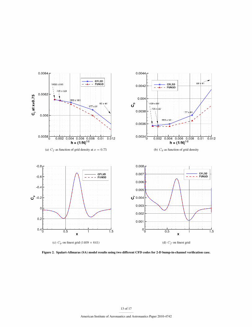
Some results using SA are shown in Figs. 2(a)-(c), and results using SST-V are shown in Figs. 3(a)-(c). The twoCFD codes – structured code CFL3D11 and unstructured code FUN3D12 – approach nearly identical results as the gridis refined (h → 0, where h represents a measure of the mean grid spacing
√1/N , with N the number of grid points).
With two different independent codes yielding the same results on a sufficiently fine grid, one can more confidentlyassert that the models have been implemented correctly. Many detailed results from these two codes are provided onthe website for this case, including the field variables eddy viscosity for SA, and eddy viscosity, k, and ω for SST-V.
D. Validation Cases
A large percentage of industry respondents of the industry survey (see Appendix) felt that the emphasis of benchmark-ing efforts should be placed on complex flows. The working group discussed this issue extensively, but decided tofocus only on several relatively simple flows for the purposes of the website. With simple flows, it is easier to ensuregrid converged solutions, easier for multiple codes to be employed on the same problem, and often easier to find reli-able and well-documented experiments. With complex flows (such as 3-D, large separations, etc.), one is usually notsure whether disagreement with experiment is caused by the turbulence model or some other factor. See, for example,the discussion in section 1.1 of Rumsey et al.13
The working group has decided to include five validation cases on the website. Three of these are still in theprocess of being evaluated, so are listed as tentative:
• 2-D incompressible zero pressure gradient flat plate14–16
• 2-D incompressible NACA 0012 airfoil17–19
• 2-D incompressible planar shear20 (tentative)
• Axisymmetric incompressible adverse pressure gradient separated flow21 (tentative)
• 2-D compressible supersonic zero pressure gradient flat plate22 (tentative)
Theory and data have been posted to the website for the first two of these cases, and initial efforts have been madetoward obtaining CFD results for certain turbulence models using multiple codes. Some of these results are describedhere.
1. 2-D Incompressible Zero Pressure Gradient Flat Plate
For the flat plate, the validation case is the same as the verification case. The flow conditions are M = 0.2, Re = 10million based on the full length of the plate (L = 2), or Re = 5 million per unit length. Grid sizes ranged all the wayfrom the finest 545×385 to the coarsest 35×25, and all were members of the same grid family, achieved by removingevery other point in each coordinate direction for each coarser grid level. The finest grid had a wall normal spacing ofy = 5× 10⁻⁷, yielding an average y+ of approximately 0.1 over the plate.
At the present time, results have been obtained using two models – SA and SST-V – with the two codes CFL3Dand FUN3D. The CFD computations are compared against the Karman-Schoenherr formula14 for skin friction as afunction of Reθ in Fig. 4(a), and the velocity profiles based on wall variables from Coles15 at Reθ = 10,000 inFig. 4(b). The comparisons are made using Reθ as opposed to an absolute x-location on the plate in order to avoidissues with transitional flow behavior of different models at the leading edge of the plate.
5 of 17
American Institute of Aeronautics and Astronautics Paper 2010-4742
It should be noted that computing Reθ typically involves an additional post-processing step for many CFD codes(numerically integrating to obtain the momentum thickness θ). Although this step is relatively straightforward for theflat plate, nonetheless some numerical errors are unavoidably introduced which may vary depending on the postpro-cessing program employed. When viewing comparisons, this additional potential source of error should be taken intoconsideration.
Results were indistinguishable on the finest 545× 385 grid for the two codes CFL3D and FUN3D, so only resultsfrom CFL3D on that grid are shown. Both turbulence models yielded Cf levels that are between about 1 and 4% lowcompared to the Karman-Schoenherr formula in the range of 4000 < Reθ < 13000 (the error is smallest toward thehigh end of the Reθ range). However, both fell within the band (shown as the shaded region in Fig. 4(a)) defined byan array of different correlations (see White16). The velocity profiles are in very good agreement with theory in termsof wall variables, with the biggest differences between the two models occurring near the knee at the bottom end ofthe log layer.
2. 2-D Incompressible NACA 0012 Airfoil
For the NACA 0012 airfoil validation case, the conditions are M = 0.15, Re = 6 million per chord. The definition ofthe NACA 0012 airfoil is slightly altered so that the airfoil closes with a sharp trailing edge at a chord length of 1. Todo this, the exact NACA 0012 formula is used, then the airfoil is scaled down by 0.99114864. The scaled formula canbe written:
y = ±0.594689181(0.298222773√
x− 0.127125232x− 0.357907906x2
+0.291984971x3 − 0.105174696x4) (3)
To minimize issues associated with the effect of the farfield boundary (which can particularly influence drag and liftlevels at high lift conditions), grids have been provided with the farfield boundary located approximately 500 chordsaway from the airfoil. Otherwise, a “farfield point vortex” boundary condition correction should be employed.23 Theeffect of farfield extent on drag coefficient is shown in Fig. 5(a), for an angle of attack of 15◦, both without and with afarfield point vortex correction. Using an extent of 30c and no correction, the drag coefficient was more than 4% toohigh, whereas using the 30c extent with the correction, the error was only 0.3%. Using a 500c extent, the computationwith no correction was also only 0.3% in error.
Grid sizes for the NACA 0012 ranged from the finest 1793 × 513 to the coarsest 113 × 33. The finest grid hadminimum spacing at the wall of y = 4× 10⁻⁷, giving an approximate average y+ between 0.1 and 0.2 over the airfoilat the Reynolds number run. The grid was stretched in the wall-normal direction, and the clustering was maintained inthe wake region. The topology is a so-called “C-grid,” with the grid wrapping around the airfoil from the downstreamfarfield, around the lower surface to the upper, then back to the downstream farfield again; the grid connected to itselfin a 1-to-1 fashion in the wake. There were 1025 points on the airfoil surface on the finest grid, and 385 points alongthe wake from the airfoil trailing edge to the outflow boundary.
The NACA 0012 validation case has been run with several different CFD codes at angles of attack of 0◦, 10◦,and 15◦. At these conditions, it was found that the 897 × 257 grid size was fine enough to produce reasonably lowdiscretization errors. For example, Fig. 5(b) shows a plot of the lift and drag coefficients vs. mean grid spacing h usingCFL3D with SA at α = 15◦. As the grid density increases (h → 0), the lift increases and the drag decreases. Usingerror estimating procedures from Celik et al.,24 on the 897 × 257 grid with CFL3D, the lift error is approximately0.13%, and the drag error is approximately 1.52% compared to an extrapolated infinite grid size (rate of convergenceis approximately second order).
Results from four different CFD codes using SA are shown in Figs. 6 and 7. Three of the codes (CFL3D11 ofNASA Langley, NTS25 of NTS in Russia, and TURNS26 of Stanford and University of Maryland) used the same897× 257 grid, while one code (GGNS27 of Boeing) was grid-adaptive. All four codes yielded similar results for CL,CD, Cp, and Cf , and were also in very good agreement with available experimental data. It is important to note thatuntripped wind tunnel data in the range of interest here (near Re = 6 million) produces a drag that is about 10% lower(at α = 0◦) than tripped data.17 For comparing with “fully turbulent” CFD computations, it is appropriate to comparewith tripped data. Here, we compare the computed forces with tripped data of Ladson18 in Fig. 6.
For surface pressures, a significant number of available NACA 0012 experimental data appear to rapidly lose two-dimensionality with increasing angle of attack. The best pressure data we have found to date is that of Gregory andO’Reilly,19 although it is at a lower Reynolds number of 3 million (believed to have little influence on Cp for the rangeconsidered). The CFD results are compared to this Cp data in the left-hand column of Fig. 7. No experimental data is
6 of 17
American Institute of Aeronautics and Astronautics Paper 2010-4742

available for Cf , but the CFD results are compared to each other in the right-hand column of the same figure. Withoutan experimental baseline, the Cf results are not technically part of the validation study, but the results do indicate thelevel of agreement between different codes.
E. Other Resources on the Website
In addition to having data, grids, and CFD solutions from multiple codes for the 5 planned validation cases, the websitealso serves as a repository for the turbulent flow validation databases described in Bradshaw et al.28 These databasesconsist of experimental data and simulation results for a wide variety of cases, with an emphasis on complex (stronglynonequilibrium) flows. The validation data were provided courtesy of P. Bradshaw of Stanford University. Part ofthe group consists of incompressible and compressible flow cases from the 1980-81 Data Library.29 There are alsoadditional data from measurements taken in later years, and some reference computations.
The website also provides some information from a series of turbulence-related Validation and Verification (V&V)workshops held in Lisbon, Portugal, at the Instituto Superior Tecnico (IST). The information includes manufacturedsolutions for wall-bounded incompressible turbulent flow, courtesy of the workshop organizer L. Eca of IST. FOR-TRAN files are included and are available for download. Additional details about the three workshops can be foundin refs. 30 – 32. See also Eca et al.33, 34 for details on the construction of manufactured solutions for several one- andtwo-equation eddy-viscosity turbulence models.
III. Future Plans
The Turbulence Modeling Resource website continues to be populated and updated by the TMBWG. In the nearfuture, the group would like to expand the number of turbulence models described and referenced on the site. Amongthose being considered are the v2-f model,35 the lag model,36 the k-ζ model,37 the k-l model,38 and some form orforms of the k-ε model.39, 40 It is anticipated that models on the site will be rated according to the model readinessrating system described earlier. Also in the near term, the TMBWG plans to finish defining the five validation cases,then compute each with at least two different CFD codes. At first, the focus will be on some form(s) of the Spalart-Allmaras and Menter k-ω SST turbulence models, because these two are currently among the most commonly usedfor aerospace applications. In the longer term, it is hoped that each of the verification and validation cases can also becomputed using other turbulence models. It is possible that additional verification or validation cases will be definedif the need arises.
Acknowledgments
The authors gratefully acknowledge Philippe Spalart and Steve Allmaras of Boeing, Karthik Duraisamy of Stan-ford, and Misha Strelets of NTS for their generous help computing and supplying NACA 0012 results.
Appendix
When the TMBWG was first formed, an internal survey was taken of its members regarding RANS turbulencemodeling. This survey was subsequently changed into a multiple choice version and was distributed widely to variousorganizations throughout the CFD community. The purpose of the surveys was to help insure that the TMBWG’sactivities are relevant to the CFD community. Nine active TMBWG group members responded to the initial survey,and 108 responses were received from the industry survey. Summaries of both surveys are provided below.
Preliminary Internal Survey
1. Given the developments of LES and DNS methods, how long will RANS turbulence models be in wide use,either alone, or in combination with a hybrid RANS/LES method for aerospace development and design?
• Respondents believed that RANS models will likely be in use for between 20 – 50 years.
• RANS models will likely be a critical part of hybrid schemes during this period.
• RANS models will complement LES methods, being used heavily for design and optimization, placeswhere LES methods are too expensive for quick-turnaround design.
7 of 17
American Institute of Aeronautics and Astronautics Paper 2010-4742

2. How critical is the accuracy of RANS turbulence models to the successful application of CFD in aerospaceresearch, development, and design?
• Most felt importance was case dependent. Accuracy is less critical in some cases because (a) currently wedo not have grid-converged solutions for many complex applications, and (b) currently, when CFD is usedto determine trends and increments, absolute accuracy is not required.
• Turbulence model accuracy will likely become more important in the future as grid converged solutionsbecome more common.
3. Are RANS turbulence models today sufficiently accurate?
• For attached flows, RANS models are for the most part accurate.
• For separated flows, RANS models are for the most part not sufficiently accurate.
• For many specific flow phenomena, current RANS models are judged to be inaccurate: e.g., high Machnumber, high curvature, mixing, scalar transport, and reattachment and recovery region.
4. Recognizing that there are different types of wall functions with different degrees of accuracy, are wall functionsa useful complement to a RANS turbulence model today? Do you feel they will continue to be useful 5-15 yearsin the future?
• Can be very useful in regions of a computation where user wants to account for viscous effects, but flow isrelatively benign – for example, test section walls.
• Wall functions help to ensure reasonable results for users who do not carefully control near wall spacing.
• Some respondents felt that their use should be minimized – wall functions introduce needless simplifica-tions and inaccuracies.
• The utility of wall functions is linked to the inaccuracy of near wall region modeling in many turbulencemodels.
• Wall function accuracy depends on (a) whether streamwise pressure gradients are accounted for, and (b)how they behave in separated flows.
5. Do you believe that it is possible to significantly improve the accuracy of turbulence models for use in a pre-dictive way so that the model is essentially either universally applicable, or is applicable over a relatively broadrange of applications (classes such as incompressible flows, compressible flows, or attached flows with smallseparation bubbles), or is RANS turbulence modeling at a level of maturity where further improvement is diffi-cult to achieve and has minimal impact?
• Progress toward a universally accurate model is unlikely.
• Although major improvements seem unlikely in today’s environment, anything is possible.
• Improvements for many specific flows – for example, flows with small separation bubbles and reattachmentregions – should be possible.
• Phenomena specific improvements could be incorporated in a general modeling scheme through zonalmodeling or automated parameter adjustment.
6. Do you believe that there has been significant improvement in the accuracy of RANS turbulence models typicallyapplied in industry in the past 10 years?
• There has been minimal improvement.
• Last major improvements: SST model and EASM maturation.
• There has been minimal attention paid to the dissipation length scale equation, and this is one area whereresearch could pay dividends.
7. Do you have confidence that when a specific turbulence model is implemented in multiple commercial or readilyavailable government codes that consistent results will be obtained?
8 of 17
American Institute of Aeronautics and Astronautics Paper 2010-4742

• Mostly, confidence was low, due to (a) coding limiters or tweaks to improve robustness (but which changeresults), (b) coding errors, (c) incomplete or inconsistent model documentation so multiple versions are inexistence, or (d) implementations without consultation or involvement of model developer.
8. Do you feel there is a need for improved documentation and expanded benchmarking of turbulence models?
• Improved documentation is sorely needed, especially to help sort out confusion due to multiple versionsof a model.
• It would be particularly useful to have documentation and benchmarking provided and on-line.
9. If you believe there is a need for expanded benchmarking of turbulence models, is there a value in allowingmultiple model developers to benchmark models using different CFD flow solvers, or does this effort have to beperformed by a limited group of qualified experts to be useful?
• Consensus not reached on this question.
• Having an independent researcher implement and benchmark is ideal, but impractical.
10. What types of flow cases should be the emphasis of a benchmarking effort – simple turbulent flows, or complexflows?
• Consensus not reached on this question.
• Simple test cases are more practical (simplify work for developers, make checking easier, and allow spe-cific phenomena to be isolated).
• User community is typically interested in specific, often complex flows, for which grid convergence canbe an issue and it is impractical to run many codes and models.
11. What types of flows present a great challenge to RANS turbulence modeling yet you believe should be possibleto predict, but are unable to predict with accuracy today?
• Extensive list generated, including: reattachment and recovery regions, multi-element airfoils, 3-D at-tached boundary layers, tip/edge vortices, round jet-plane jet anomaly, high compressibility, scalar trans-port, compressible mixing layers, transitional flow regions, and contained separated flows.
Industry Survey
For the industry survey, most of the respondents were in an aerospace-related industry (such as fluids engineering, heattransfer, turbomachinery, etc.). But there were representatives from a broad range of industries, including chemicalengineering, automotive, environmental, materials, petroleum, wind, noise, fire, blast, pipeline, and thermal protection.Most had a PhD, and over 93% had at least an MS degree. One third had more than 20 years experience in CFD, witha wide spread in age range (average age was 45). The areas of expertise were widely distributed among the categoriesof code users, code developers, solver developers, and turbulence modelers. The original survey can be found at theTurbulence Modeling Benchmarks Survey website d.
1. Given the developments of LES and DNS methods, how long will RANS turbulence models continue to bein wide use either alone or in combination with a hybrid RANS/LES method for aerospace development anddesign?
• 21% believed it will end in 5–10 years.
• The largest percentage (36%) believed 10–20 years.
• 22% believed the end will not come for at least 40 years.
• In general, modelers predicted the longest lifetime for RANS, followed by solver developers, then codedevelopers, then users.
2. How critical is the accuracy of RANS turbulence models to the successful application of CFD in aerospaceresearch, development and design?
dhttp://www.engineering.wright.edu/mme/tmb-survey.phtml, cited: 4/19/2010.
9 of 17
American Institute of Aeronautics and Astronautics Paper 2010-4742
• Majority (68%) believed it is either very or extremely critical.
• The most critical area is the detailed design stage (as opposed to the preliminary design stage).
3. Are today’s RANS turbulence models sufficiently accurate? (various flows listed)
• Most had confidence for simple flows (e.g., wall-bounded flows with mild pressure gradient), but were lessconfident for complex flows (e.g., significant separation, curvature, shock-boundary layer interaction).
• Overall, most respondents felt they are “somewhat” to “very” accurate.
4. In which areas do you believe the accuracy of RANS turbulence models typically applied in industry have beenimproved in the past 10 years? (various flows listed)
• The respondents generally felt there have been improvements for simple flows, but less so for complexflows.
5. In which areas do you believe the accuracy of RANS turbulence models can be improved in the next 10 years?(various flows listed)
• It appeared that respondents generally believed the same scale of successes they observed for the simpleflows in the past 10 years may apply to complex flows in the next 10 years.
6. Do you believe that it is possible to significantly improve the accuracy of RANS turbulence models so that amodel is either universally applicable, or is applicable over a relatively broad range of applications (classes suchas incompressible flows, or compressible flows, or attached flows with small separation bubbles), or is RANSturbulence modeling at a level of maturity where further improvement is both difficult and of minimal impact?
• The largest percentage (47%) felt “some improvement possible” (middle response).
• As a group, modelers were more hopeful than the others.
7. Recognizing that there are different types of wall functions with different degrees of accuracy, are wall functionsa useful complement to a RANS turbulence model today and in the next 5-15 years?
• A majority (72%) believed they are and will continue to be either reasonably, very, or extremely useful.
• As a group, modelers were least favorable toward the use of wall functions.
8. How confident are you that consistent results will be obtained when a specific turbulence model is implementedin multiple commercial or readily available government codes?
• Most (59%) had either no confidence or were only somewhat confident.
• Among them, those with the lowest confidence tended to be modelers and code developers.
9. How would you assess the level of need for improved documentation and expanded benchmarking of turbulencemodels?
• Most (77%) felt there is a significant or critical need.
10. If you believe there is a need for expanded benchmarking of turbulence models, is there a value in allowingmultiple model developers to benchmark models using different CFD flow solvers? (The alternative is to assignthe benchmarking to a limited group of qualified experts.)
• The largest percentage (50%) believed benchmarking using different people with different codes is ofsignificant value.
11. What types of flow cases should be the emphasis of a benchmarking effort?
• The largest percentage (39%) believed the emphasis should be placed on complex flows.
10 of 17
American Institute of Aeronautics and Astronautics Paper 2010-4742

References1Standard for Verification and Validation in Computational Fluid Dynamics and Heat Transfer, ASME V&V 20-2009, The American Society
of Mechanical Engineers, Nov. 2009.2Rumsey, C. L., “Consistency, Verification, and Validation of Turbulence Models for Reynolds-Averaged Navier-Stokes Applications,” ac-
cepted for publication in Proceedings of the Institution of Mechanical Engineers, Part G, Journal of Aerospace Engineering, 2010; see also: PaperEUCASS2009-7, 3rd European Conference for Aerospace Sciences, Versailles, France, July 6–9, 2009.
3Bardina, J. E., Huang, P. G., and Coakley, T. J., “Turbulence Modeling Validation, Testing, and Development,” NASA TM 110446, April1997.
4Marvin, J. G. and Huang, G. P., “Turbulence Modeling – Progress and Future Outlook,” NASA TM 110414, August 1996.5Spalart, P. R. and Allmaras, S. R., “A One-Equation Turbulence Model for Aerodynamic Flows,” Recherche Aerospatiale, No. 1, 1994, pp.
5–21.6Menter, F. R., “Two-Equation Eddy-Viscosity Turbulence Models for Engineering Applications,” AIAA Journal, Vol. 32, No. 8, August 1994,
pp. 1598–1605.7Wilcox, D. C., Turbulence Modeling for CFD, 3rd edition, DCW Industries, Inc., La Canada CA, 2006.8Rumsey, C. L. and Gatski, T. B., “Summary of EASM Turbulence Models in CFL3D with Validation Test Cases,” NASA/TM-2003-212431,
June 2003.9Hellsten, A., “New Advanced k-omega Turbulence Model for High-Lift Aerodynamics,” AIAA Journal, Vol. 43, No. 9, 2005, pp. 1857–1869.10Shur, M., Strelets, M., Zaikov, L., Gulyaev, A., Kozlov, V., and Secundov, A., “Comparative Numerical Testing of One- and Two-Equation
Turbulence Models for Flows with Separation and Reattachment,” AIAA Paper 95-0863, January 1995.11Krist, S. L., Biedron, R. T., and Rumsey, C. L., “CFL3D User’s Manual (Version 5.0),” NASA TM-1998-208444, June 1998.12Nielsen, E. J. and Anderson, W. K., “Recent Improvements in Aerodynamic Design Optimization On Unstructured Meshes,” AIAA Journal,
Vol.40, No. 6, 2002, pp. 1155–1163.13Rumsey, C. L., Allison, D. O., Biedron, R. T., Buning, P.G., Gainer, T. G., Morrison, J. H., Rivers, S. M., Mysko, S. J., and Witkowski, D.
P., “CFD Sensitivity Analysis of a Modern Civil Transport Near Buffet-Onset Conditions,” NASA/TM-2001-211263, December 2001.14Schoenherr, K. E., “Resistances of Flat Surfaces Moving Through a Fluid,” Trans. SNAME, Vol. 40, 1932, pp. 279–313.15Coles, D., “The Law of the Wake in the Turbulent Boundary Layer,” J. Fluid Mech., Vol. 1, 1956, pp. 191–226.16White, F. M., Viscous Fluid Flow, McGraw-Hill Book Company, New York, 197417McCroskey, W. J., “A Critical Assessment of Wind Tunnel Results for the NACA 0012 Airfoil,” AGARD CP-429, July 1988; also NASA
TM 100019, October 1987.18Ladson, C. L., “Effects of Independent Variation of Mach and Reynolds Numbers on the Low-Speed Aerodynamic Characteristics of the
NACA 0012 Airfoil Section,” NASA TM 4074, October 1988.19Gregory, N. and O’Reilly, C. L., “Low-Speed Aerodynamic Characteristics of NACA 0012 Aerofoil Sections, including the Effects of
Upper-Surface Roughness Simulation Hoar Frost,” NASA R&M 3726, Jan 1970.20Bradbury, L. J. S. and Riley, J., “The Spread of a Turbulent Plane Jet into a Parallel Moving Airstream,” Journal of Fluid Mechanics, Vol. 27,
Part 2, 1967, pp. 381–394.21Driver, D. M., “Reynolds Shear Stress Measurements in a Separated Boundary Layer Flow,” AIAA Paper 91-1787, June 1991.22Van Driest, E. R., “Problem of Aerodynamic Heating,” Aeronautical Engineering Review, Vol. 15, October 1956, pp. 26–41.23Thomas, J. L. and Salas, M. D., “Far-Field Boundary Conditions for Transonic Lifting Solutions to the Euler Equations,” AIAA Journal,
Vol. 24, No. 7, 1986, pp. 1074–1080.24Celik, I. B., Ghia, U., Roache, P. J., Freitas, C. J., Coleman, H., and Raad, P. E., “Procedure for Estimation and Reporting of Uncertainty
Due to Discretization in CFD Applications,” Journal of Fluids Engineering, Vol. 130, July 2008, 078001.25Shur, M., Strelets, M., and Travin, A., “High-Order Implicit Multi-Block Navier-Stokes Code: Ten-Year Experience of Application to
RANS/DES/LES/DNS of Turbulence,” 7th Symposium on Overset Grids & Solution Technology, October 5-7, 2004, Huntington Beach, CA, USA.26Duraisamy, K., “Studies in Tip Vortex Formation, Evolution and Control,” PhD Thesis, Department of Aerospace Engineering, University
of Maryland, 2005.27Venkatakrishnan, V., Allmaras, S. R., Kamenetskii, D., and Johnson, F. T., “Higher Order Schemes for the Compressible Navier-Stokes
Equations,” AIAA Paper 2003-3987, June 2003.28Bradshaw, P., Launder, B. E., and Lumley, J. L., “Collaborative Testing of Turbulence Models,” Journal of Fluids Engineering, Vol. 118,
June 1996, pp. 243–247.29“The 1980-81 AFOSR-HTTM Stanford Conference on Complex Turbulent Flows: A Comparison of Computation and Experiment,” Volumes
I, II, and III, edited by S. J. Kline, B. J. Cantwell, and G. M. Lilley, Stanford University, 1981.30Eca, L., Hoekstra, M., and Roache, P. J., “Verification of Calculations: an Overview of the Lisbon Workshop,” AIAA Paper 2005-4728, June
2005.31Eca, L., Hoekstra, M., and Roache, P. J., “Verification of Calculations: an Overview of the 2nd Lisbon Workshop,” AIAA Paper 2007-4089,
June 2007.32Eca, L., Hoekstra, M., Roache, P. J., and Coleman, H. W., “Code Verification, Solution Verification and Validation: an Overview of the 3rd
Lisbon Workshop,” AIAA Paper 2009-3647, June 2009.33Eca, L., Hoekstra, M., Hay, A., and Pelletier, D., “On the Construction of Manufactured Solutions for One and Two-Equation Eddy-Viscosity
Models,” Int. J. Numer. Meth. Fluids, Vol. 54, 2006, pp. 119–154.34Eca, L., Hoekstra, M., Hay, A., and Pelletier, D., “A Manufactured Solution for a Two-Dimensional Steady Wall-Bounded Incompressible
Turbulent Flow,” Int. J. Computational Fluid Dynamics, Vol. 21, Nos. 3–4, pp. 175–188.35Durbin, P. A., “Separated Flow Computations with the k-ε-v2 Model,” AIAA Journal, Vol. 33, No. 4, April 1995, pp. 659–664.36Olsen, M. E., Lillard, R. P., and Coakley, T. J., “The Lag Model Applied to High Speed Flows,” AIAA Paper 2005-101, January 2005.37Robinson, D. F. and Hassan, H. A., “Further Development of the k-ζ (Enstrophy) Turbulence Closure Model,” AIAA Journal, Vol. 36, No. 10,
1998, pp. 1825–1833.
11 of 17
American Institute of Aeronautics and Astronautics Paper 2010-4742

38Smith, B. R., “Prediction of Hypersonic Shock-Wave / Turbulent Boundary-Layer Interactions,” Journal of Spacecraft and Rockets, Vol. 33,No. 5, Sept.-Oct. 1996, pp. 614–619.
39Jones, W. P. and Launder, B. E., “The Calculation of Low-Reynolds-Number Phenomena with a Two-Equation Model of Turbulence,” Int.J. Heat Mass Transfer, Vol. 16, 1973, pp. 1119-1130.
40Craft, T. J., Launder, B. E., and Suga, K., “Development and Application of a Cubic Eddy-Viscosity Model of Turbulence,” Int. J. Heat andFluid Flow, Vol. 17, 1996, pp. 108–115.
(a) farfield (b) close-up of bump
Figure 1. Boundary conditions for 2-D bump-in-channel verification case.
12 of 17
American Institute of Aeronautics and Astronautics Paper 2010-4742
(a) Cf as function of grid density at x = 0.75 (b) Cd as function of grid density
(c) Cp on finest grid (1409 × 641) (d) Cf on finest grid
Figure 2. Spalart-Allmaras (SA) model results using two different CFD codes for 2-D bump-in-channel verification case.
13 of 17
American Institute of Aeronautics and Astronautics Paper 2010-4742
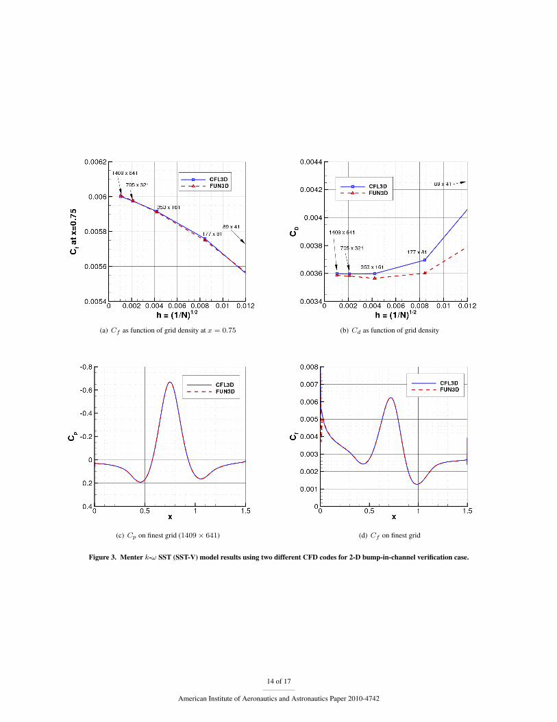
(a) Cf as function of grid density at x = 0.75 (b) Cd as function of grid density
(c) Cp on finest grid (1409 × 641) (d) Cf on finest grid
Figure 3. Menter k-ω SST (SST-V) model results using two different CFD codes for 2-D bump-in-channel verification case.
14 of 17
American Institute of Aeronautics and Astronautics Paper 2010-4742
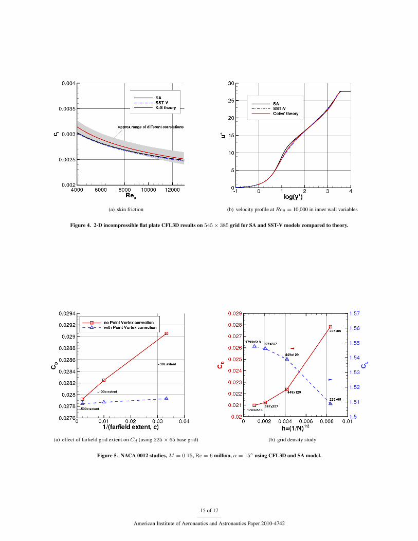
(a) skin friction (b) velocity profile at Reθ = 10,000 in inner wall variables
Figure 4. 2-D incompressible flat plate CFL3D results on 545 × 385 grid for SA and SST-V models compared to theory.
(a) effect of farfield grid extent on Cd (using 225 × 65 base grid) (b) grid density study
Figure 5. NACA 0012 studies, M = 0.15, Re = 6 million, α = 15◦ using CFL3D and SA model.
15 of 17
American Institute of Aeronautics and Astronautics Paper 2010-4742
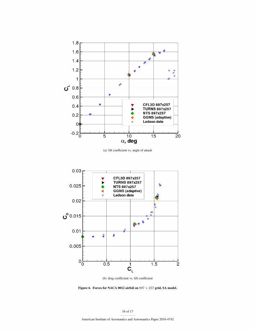
(a) lift coefficient vs. angle of attack
(b) drag coefficient vs. lift coefficient
Figure 6. Forces for NACA 0012 airfoil on 897 × 257 grid, SA model.
16 of 17
American Institute of Aeronautics and Astronautics Paper 2010-4742
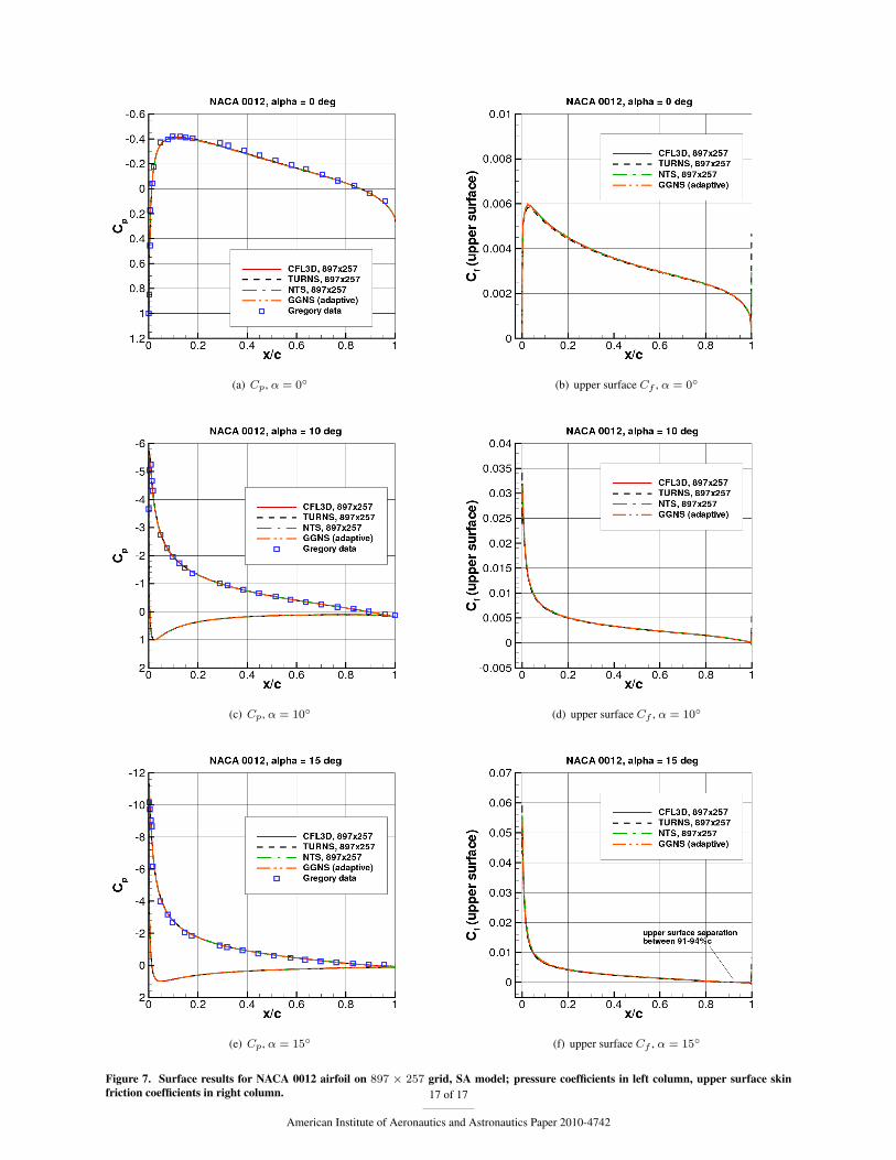
(a) Cp, α = 0◦ (b) upper surface Cf , α = 0◦
(c) Cp, α = 10◦ (d) upper surface Cf , α = 10◦
(e) Cp, α = 15◦ (f) upper surface Cf , α = 15◦
Figure 7. Surface results for NACA 0012 airfoil on 897 × 257 grid, SA model; pressure coefficients in left column, upper surface skinfriction coefficients in right column. 17 of 17
American Institute of Aeronautics and Astronautics Paper 2010-4742