40mm bofors cannon for pt boats - wordpress.com bofors cannon for pt boats assembly instructions kit...
TRANSCRIPT
(c) 2016 P. Matthews
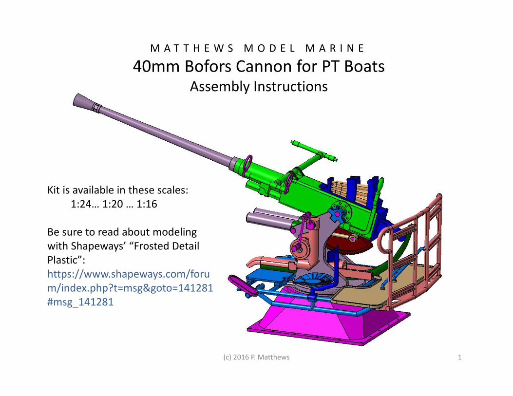
M A T T H E W S M O D E L M A R I N E
40mm Bofors Cannon for PT BoatsAssembly Instructions
Kit is available in these scales:
1:24… 1:20 … 1:16
Be sure to read about modeling
with Shapeways’ “Frosted Detail
Plastic”:
https://www.shapeways.com/foru
m/index.php?t=msg&goto=141281
#msg_141281
1
(c) 2016 P. Matthews
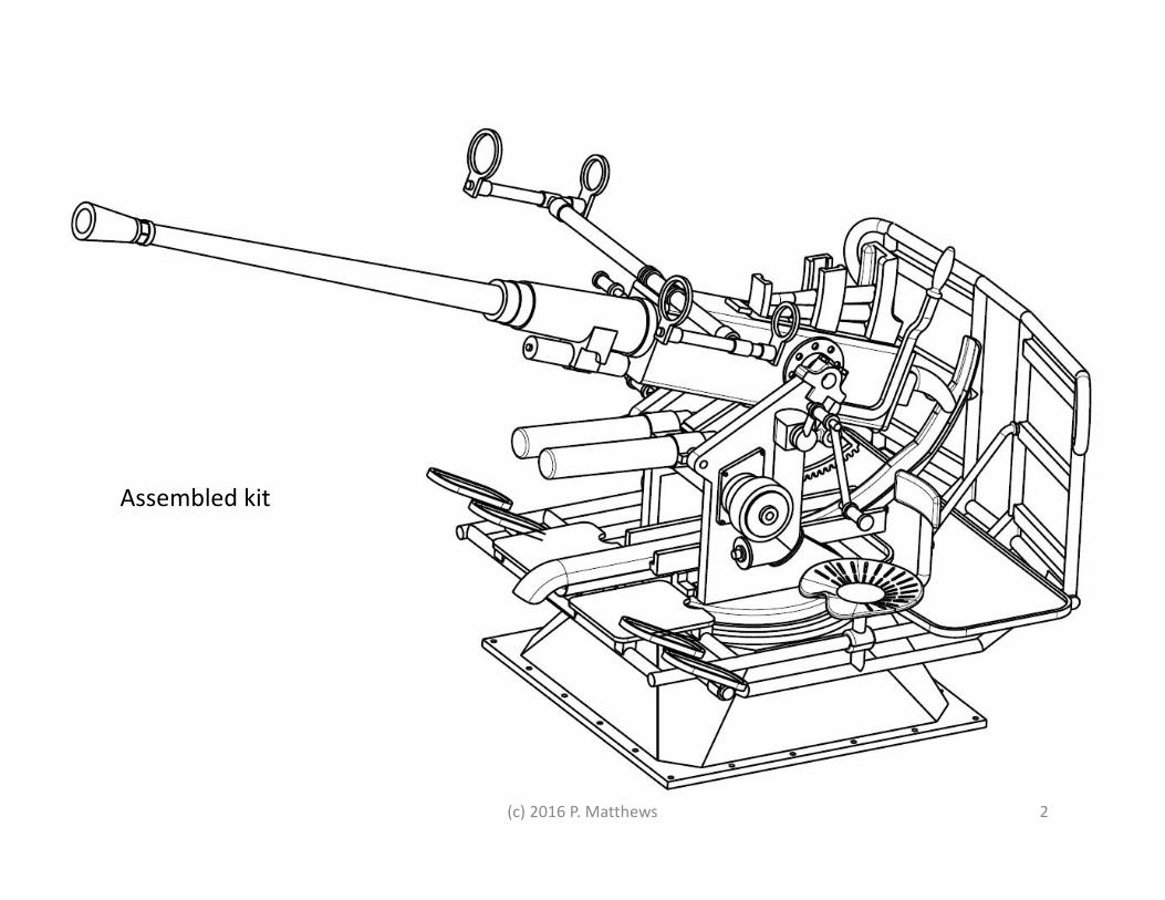
Assembled kit
2
(c) 2016 P. Matthews
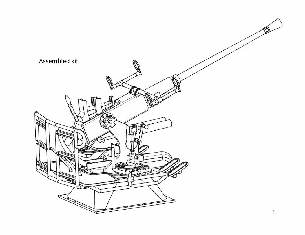
Assembled kit
3
(c) 2016 P. Matthews
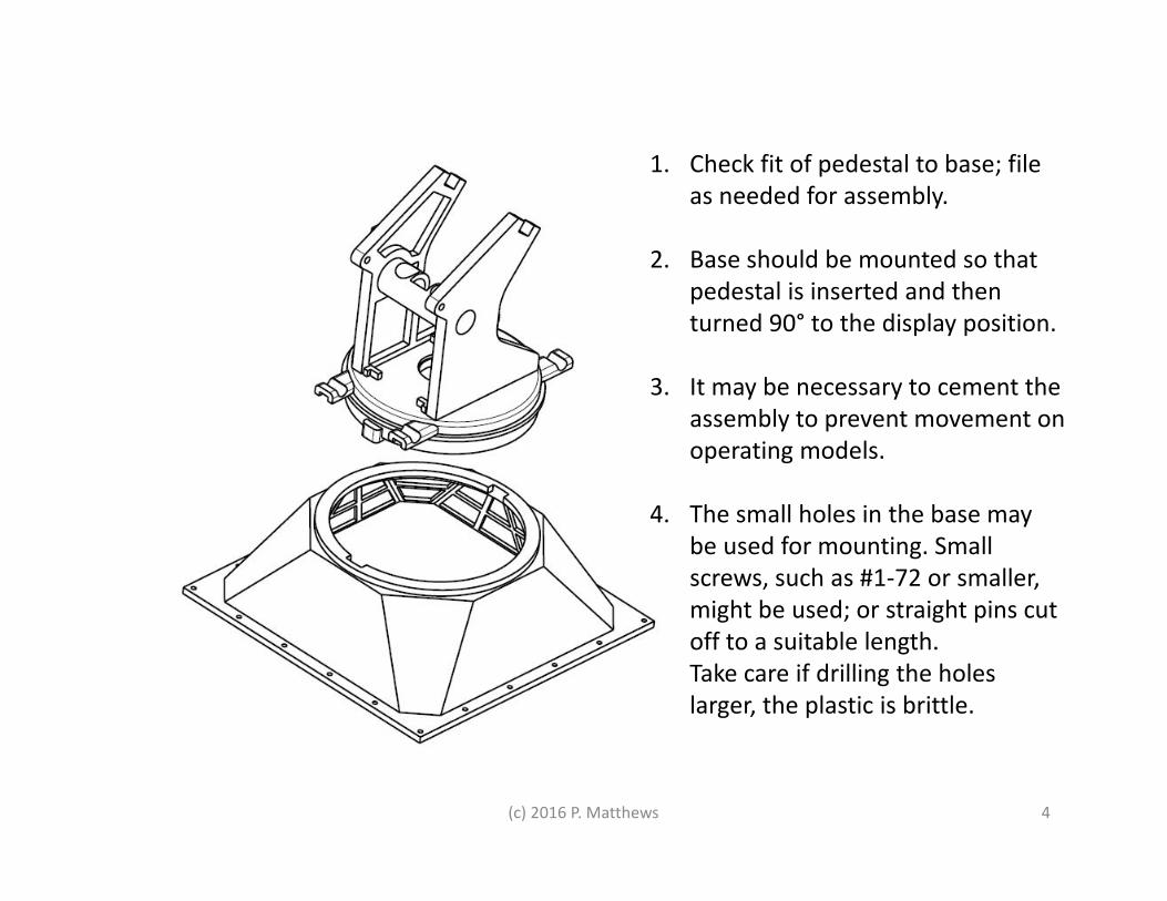
1. Check fit of pedestal to base; file
as needed for assembly.
2. Base should be mounted so that
pedestal is inserted and then
turned 90° to the display position.
3. It may be necessary to cement the
assembly to prevent movement on
operating models.
4. The small holes in the base may
be used for mounting. Small
screws, such as #1-72 or smaller,
might be used; or straight pins cut
off to a suitable length.
Take care if drilling the holes
larger, the plastic is brittle.
4
(c) 2016 P. Matthews 5
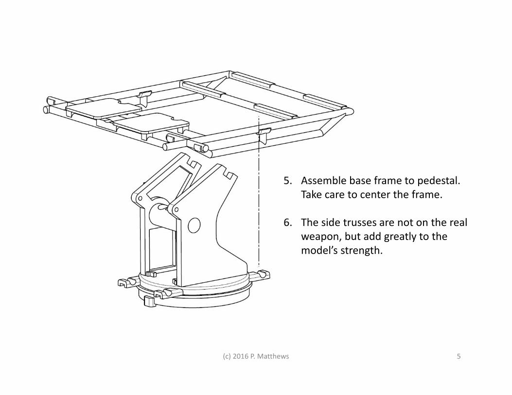
5. Assemble base frame to pedestal.
Take care to center the frame.
6. The side trusses are not on the real
weapon, but add greatly to the
model’s strength.
(c) 2016 P. Matthews 6
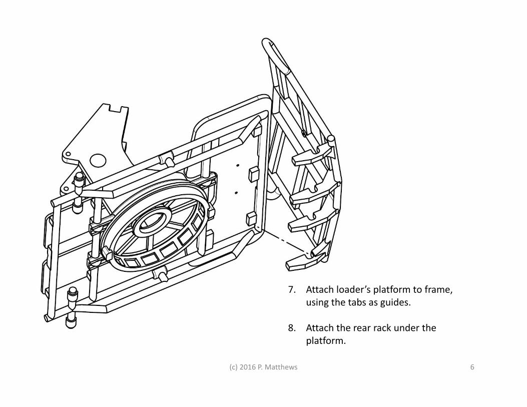
7. Attach loader’s platform to frame,
using the tabs as guides.
8. Attach the rear rack under the
platform.
(c) 2016 P. Matthews 7
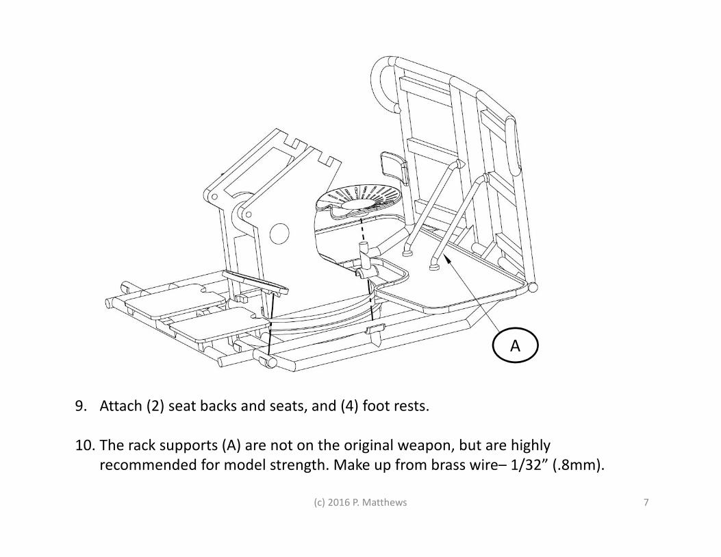
9. Attach (2) seat backs and seats, and (4) foot rests.
10. The rack supports (A) are not on the original weapon, but are highly
recommended for model strength. Make up from brass wire– 1/32” (.8mm).
A
(c) 2016 P. Matthews 8
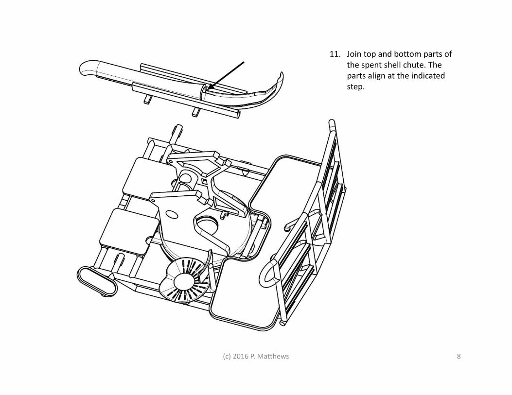
11. Join top and bottom parts of
the spent shell chute. The
parts align at the indicated
step.
(c) 2016 P. Matthews 9
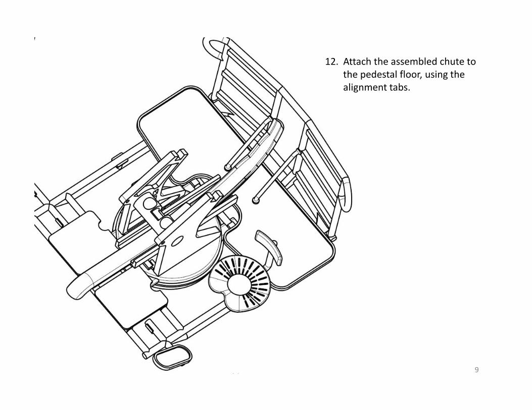
12. Attach the assembled chute to
the pedestal floor, using the
alignment tabs.
(c) 2016 P. Matthews 10
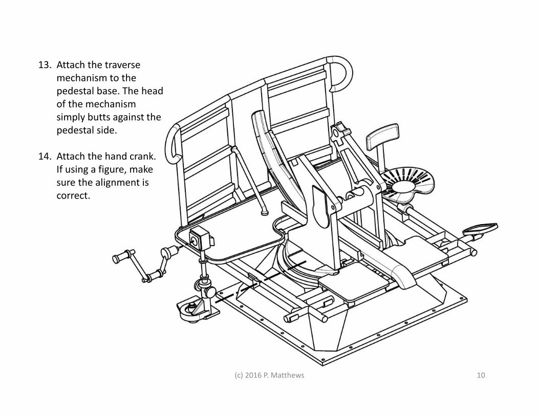
13. Attach the traverse
mechanism to the
pedestal base. The head
of the mechanism
simply butts against the
pedestal side.
14. Attach the hand crank.
If using a figure, make
sure the alignment is
correct.
(c) 2016 P. Matthews 11
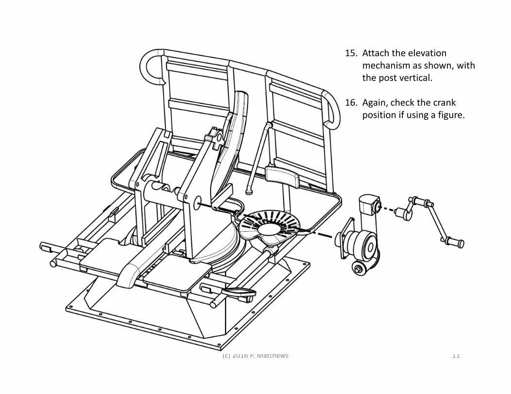
15. Attach the elevation
mechanism as shown, with
the post vertical.
16. Again, check the crank
position if using a figure.
(c) 2016 P. Matthews 12
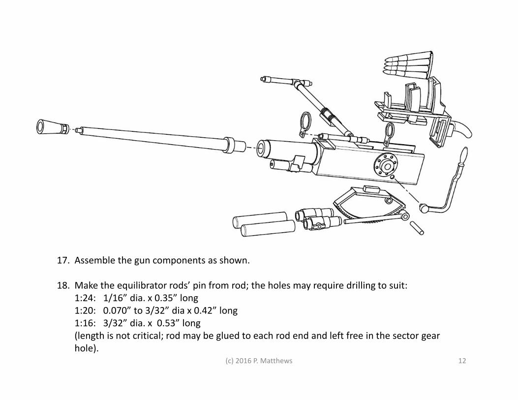
17. Assemble the gun components as shown.
18. Make the equilibrator rods’ pin from rod; the holes may require drilling to suit:
1:24: 1/16” dia. x 0.35” long
1:20: 0.070” to 3/32” dia x 0.42” long
1:16: 3/32” dia. x 0.53” long
(length is not critical; rod may be glued to each rod end and left free in the sector gear
hole).
(c) 2016 P. Matthews 13
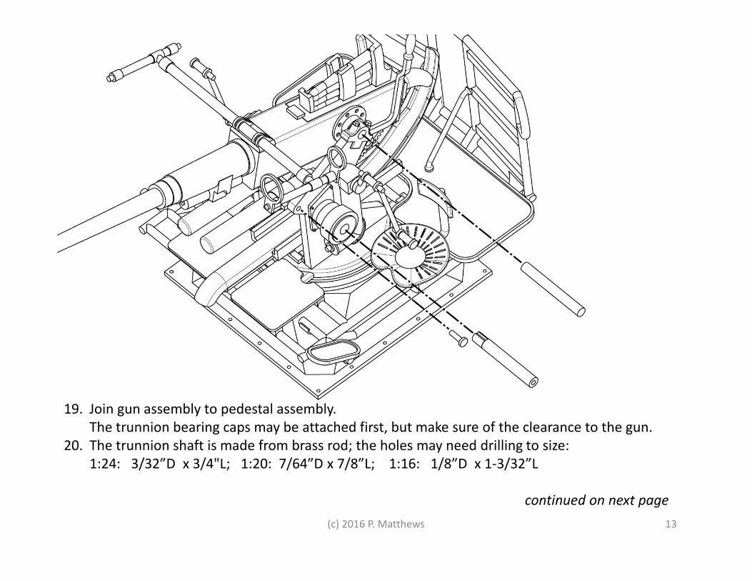
19. Join gun assembly to pedestal assembly.
The trunnion bearing caps may be attached first, but make sure of the clearance to the gun.
20. The trunnion shaft is made from brass rod; the holes may need drilling to size:
1:24: 3/32”D x 3/4"L; 1:20: 7/64”D x 7/8”L; 1:16: 1/8”D x 1-3/32”L
continued on next page
(c) 2016 P. Matthews 14
21. The equilibrator cylinders are secured with small brass screws or rod, or Tee-
shaped turnings if you have a lathe… one fastener on each side. Again, some
drilling to size may be required. Length is not critical, but pins should not foul
the equilibrator rods.
Sizes:
1:24: 3/64”D x 0.145”L
1:20: 0.052” to 1/16”D x 0.175”L
1:16: 1/16” to 0.065” D x 0.22” L
22. The elevation lock pin is optional; it allows you to set and keep the gun
elevation without gluing it in place. This is the straight plastic dowel with a
tooth on the end; it will engage with the sector gear and keeps it from
moving.
The hole in the outer end can be tapped or some more rod can be glued in to
aid in retrieving the lock pin. IT CAN BE PUSHED TOO FAR IN, making retrieval
difficult. Play with the pin in the assembly before final joining, to see how it
works.
(c) 2016 P. Matthews 15
Working with Shapeways' "Frosted Detail" Plastic
for use with Frosted Detail models from Matthews Model Marine, a shop at Shapeways
The "Frosted Detail" plastics from Shapeways are not the same as the molded styrene in your typical plastic model kit. In fact, the
Shapeways material is harder to work with, and requires some special handling. But this is the price we pay for custom parts that
can't be found anywhere else.
First: How is my part made?
Two things make this type of 3D printing possible:
1. A liquid "photopolymer" acrylic resin that can be hardened with ultraviolet (UV) light;
2. A device- a print head- which can deliver drops of the resin to particular places on the print platform.
So basically, the process is like an inkjet printer head, sweeping back and forth, spritzing out droplets of resin which are then
flashed with UV light to harden them in place. Do this in layers... layer after layer... and you build up a three dimensional part. Easy!
But there is an additional trick required:
If a new layer's edges overhang the layer below it, the droplets will fall out of place, just as surely as what happens to Wile E.
Coyote after going off a cliff. So some support is required. The printer does this by printing out droplets of a waxy material
wherever an overhang is planned, providing a soft platform for the next layer of resin.
OK, what do I have to do special?
1. Be careful with your parts. Very careful.
The parts are very brittle, nothing like the rather flexible styrene in model kits.
- Snipping a part off a sprue, when it's retained in multiple places, can shatter it. I use a very fine tooth saw while carefully
supporting the part.
Hint: Look for "EXCEL" #13 saw blades, which are super fine, and can be mounted in an Xacto handle.
- Drilling a hole can split the part open, or shatter chunks off.
- Even normal handling can break smaller parts.
- Test fit parts, but never force them... file as needed to get a happy fit.
continued…
(c) 2016 P. Matthews 16
Working with Shapeways' "Frosted Detail" Plastic
2. Wash your parts.
The support wax has been *mostly* washed off. Get the rest of it with warm water and detergent, or Simple Green or similar;
scrub gently with a toothbrush. An ultrasonic jewelry cleaner can be helpful when doing lots of parts.
3. Post-cure your plastic.
This should be taken care of by Shapeways, but it isn't. The flash of UV light that cures each layer doesn't get 100% of the resin.
And traces of uncured resin in the plastic matrix will lead to problems with paint. The cure? Post cure with a good dose of UV
light... a few hours in the sun, or under a UV-A lamp, should do the job. The real test is whether enamel primer cures on the part. If
it doesn't, wash with paint or lacquer thinner, and post-cure some more.
4. Scrape and sand your parts.
After washing and drying, you will see "frosted" surfaces wherever the support wax contacted the plastic, while areas that were on
top in the print process may be almost optically smooth. The frost and other print line artifacts can be scraped and sanded off.
Instead of just cleaning mold marks and seams, as with a commercial plastic kit, you'll need to clean the entire surface on about
half the part. Please enjoy this time spent bonding with your new model!
5. Glue with epoxy or CA (cyanoacrylate). You may need to use CA "kicker" to get the CA to set.
Note: This is an acrylic plastic, and solvent glues for styrene models won't work. Possibly solvent glues meant for Plexiglas would
work-- I haven't tried them. Also note that solvent cements work best when the joint can be held under pressure while setting.
6. If you post-cured the parts, you'll be able to paint with your choice of paints. I recommend enamel primer in all cases.
(c) 2016 P. Matthews 17
Thanks for choosing this model!
Matthews Model Marine